
Optima Plus - Uncategorized DOMETIC - Free user manual and instructions
Find the device manual for free Optima Plus DOMETIC in PDF.

| Product Type | Awning Tension Rafter / Cradle Support |
| Brand | Dometic |
| Model | Optima Plus |
| Compatible Awnings | A&E Optima Universal Plus FRTA over 21 ft |
| Adjustable Length | Up to 25 ft (full stroke for 25 ft awnings) |
| Minimum Clearance Required | 69" below awning rail |
| Mounting Location | Vehicle side wall (top bracket) and floor line/solid structural member (bottom bracket) |
| Installation Tools | Measuring tape, electric drill, drill bits (#7/3/16", 5/16"), center punch, Phillips screwdriver, silicone sealant, ladder, pencil, 7/16" wrench/socket, pop rivet gun (if needed) |
| Operation | Manual tension mechanism with adjustment knob and lever |
| Safety Certification | Must be installed by a qualified service technician or Dometic Service Center |
| Weight (estimated) | Approx. 5-10 lbs |
| Material | Aluminum/steel frame, plastic adjustment knob |
| Included Hardware | Tension rafter, top bracket/pad assembly, bottom bracket, ball lock pin, hex head bolt, lock nut, screws, push-in panel fasteners, backing support plate |
| Maintenance | Clean with mild soap and water; lubricate adjustment knob and tension mechanism as needed |
| Warranty | Not specified – contact Dometic |
Frequently Asked Questions - Optima Plus DOMETIC
User questions about Optima Plus DOMETIC
0 question about this device. Answer the ones you know or ask your own.
Ask a new question about this device
Download the instructions for your Uncategorized in PDF format for free! Find your manual Optima Plus - DOMETIC and take your electronic device back in hand. On this page are published all the documents necessary for the use of your device. Optima Plus by DOMETIC.
USER MANUAL Optima Plus DOMETIC
A&E Optima Tension Rafter/Cradle Support
USA
SERVICE OFFICE
Dometic Corporation
1120 North Main Street
Elkhart, IN 46514
CANADA
Dometic Corporation
46 Zatonski, Unit 3
Brantford, ON N3T 5L8
CANADA
SERVICE CENTER &
DEALER LOCATIONS
Please Visit:
www.eDometic.com
WARNING
This manual must be read and understood before installation, adjustment, service, or maintenance is performed. This unit must be installed by a qualified service technician. Modification of this product can be extremely hazardous and could result in personal injury or property damage.
! AVERTISSEMENT
This manual has safety information and instructions to help users eliminate or reduce the risk of accidents and injuries.
RECOGNIZE SAFETY INFORMATION

natural_image
Warning symbol: white exclamation mark inside a triangle on black background (no text or numbers)This is the safety-alert symbol. When you see this symbol in this manual, be alert to the potential for personal injury.
Follow recommended precautions and safe operating instructions.
UNDERSTAND SIGNAL WORDS
A signal word, WARNING OR CAUTION is used with the safety-alert symbol. They give the level of risk for potential injury.
WARNING
indicates a potentially hazard-
ous situation which, if not avoided, could result in death or serious injury.
in CAUTION
ntially hazard-
ous situation which, if not avoided, may result in minor or moderate injury.
CAUTION
e safety alert
symbol indicates, a potentially hazardous situation which, if not avoided, may result in property damage.
Read and follow all safety information and instructions.
WARNING
These instructions must be read and understood before installation of this kit. This kit must be installed by a Dometic Service Center or a qualified service technician. Modification of this product can be extremely hazardous and could result in personal injury or property damage.
A&E OPTIMA TENSION RAFTER SYSTEM
INSTALLATION INSTRUCTIONS
For Installation of: A&E Optima Tension Rafter/Cradle Support;
CAUTION
Optima Plus tension rafter must be
used with all Universal Plus FRTA's over 21' in length. Failure to do so could result in damage to FRTA and/or hardware.
IMPORTANT: Read and understand the entire installation procedure before starting installation.
NOTE: The Dometic Corporation assumes no liability for damages or injuries resulting from installation or operation of this product.
The Dometic Corporation reserves the right to modify appearances and specifications without notice.
INSTALLATION OF TENSION RAFTER
Tools Required:
- Measuring Tape
- Electric Drill
- Drill Bits: #7 or 3/16"; 5/16"
- Center Punch
• Phillips Screwdriver - Silicone Sealant
- ladder
- Pencil
• Wrench or Socket: 7/16" - Pop Rivet Gun (Necessary only if backing plate is needed)
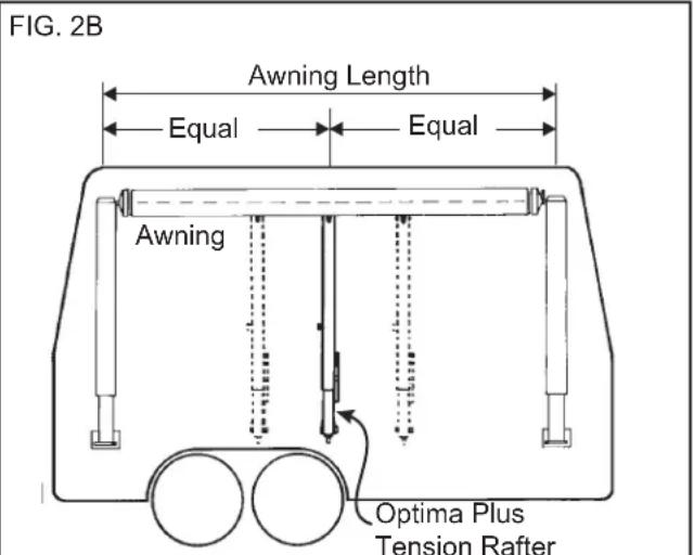
Note: When installing two tension rafters divide awning length into three equal parts.
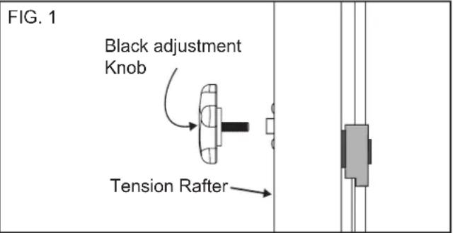
A. Install Black Adjustment Knob (see FIG.1)
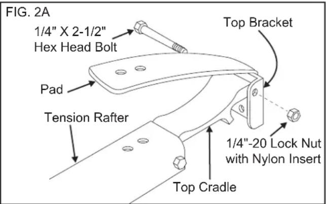
- Attach the Tension rafter to the top bracket/pad assembly with the 1/4-20 x 2-1/2" hex head bolt and 1/4-20 lock nut with nylon insert provided. (FIG 2A)
- With awning closed, position the tension rafter at the center of the awning so that it has a minimum of 69" of unobstructed clearance below the awning rail. If windows and/or service accesses interfere, relocate tension rafter as close to center of awning as the situation will allow. (See FIG. 2B).
- While holding tension rafter vertically at mounting location, carefully set roller bracket end of tension rafter on ground and loosen black adjustment knob on side of tension rafter.
- With tension rafter still resting on ground, extend the tension rafter up so that the top of the tension rafter almost touches the bottom of the closed awning.
FIG. 3
- Lock black adjustment knob on side of awning.
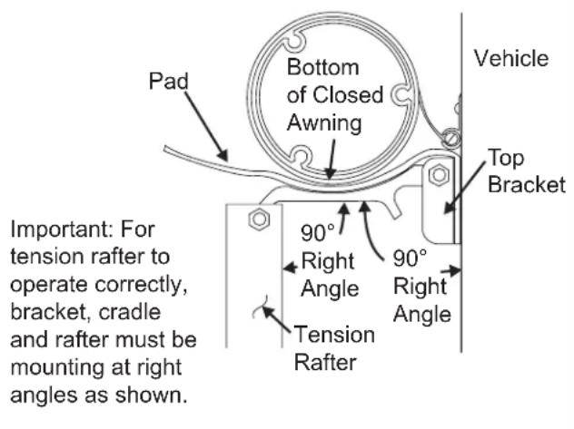
- Carefully climb ladder. With tension rafter still resting on the ground, position the top bracket/pad assembly against the vehicle so that the top cradle of the tension rafter touches the bottom of the closed awning as shown in FIG. 3.
NOTE: It may be necessary to slightly extend the tension rafter further to obtain the right angle shown in FIG. 3.
IMPORTANT: Tension rafter, top cradle, top bracket, and vehicle MUST form right angles as shown in FIG. 3 for tension rafter to operate correctly.
- Once right angles are established, mark location of mounting holes in top bracket on vehicle.
- Detach top bracket/pad assembly from tension rafter by removing the 1/4-20 x 2-1/2" hex head bolt and 1/4-20 lock nut.
B. Bracket/Pad Assembly
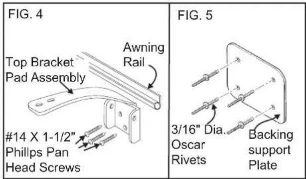
- Position top bracket/pad assembly against vehicle and predrill with #7 or 3/16" drill bit.
- Secure using three (3) #14 x 1-1/2" pan head screws provided with a small dab of silicone sealant on each screw. (See FIG. 4)
NOTE: Be sure to use a dab of silicone sealant on every screw or rivet where a hole has been drilled in the side of the vehicle. This will prevent possible water leakage.
C. Use Of Backing Support Plate (FIG. 5)
For installations where there is not sufficient support for mounting the top bracket, install the supplied backing support plate as follows:
- Using the support plate as a template, mark and drill four (4) 3/16" dia. holes through the vehicle side.
- Secure the plate using the 3/16" dia. oscar rivets provided. (See FIG. 5)
- Proceed with installation by installing the top bracket of the tension rafter directly onto the backing support plate.
D. Tension Rafter Re-Attachment
- Reattach the tension rafter to the top bracket with the 1/4-20 x 2-1/2" hex head bolt and 1/4-20 lock
nut with nylon insert provided. (See FIG. 2A)
E. Bottom Bracket Installation Postion
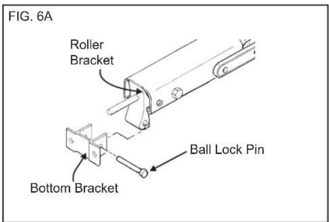
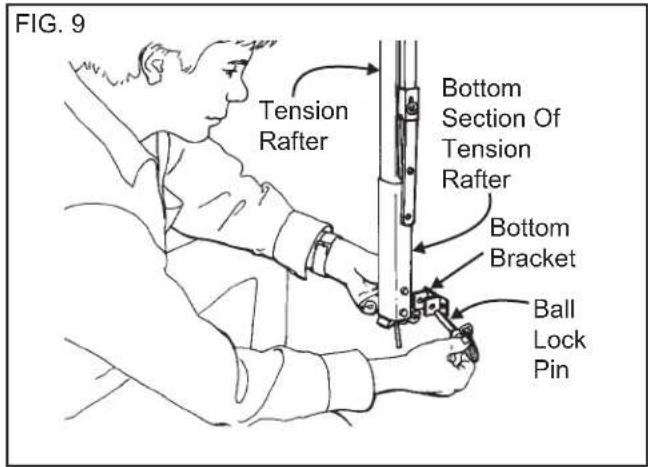
- Attach the bottom bracket to the roller bracket using the ball lock pin. (See FIG. 6A)
- Position the bottom bracket over the floorline, or solid structural member, 69" or more below the awning rail. (See FIG. 3)
IMPORTANT: The bottom bracket MUST be mounted to the floor line or solid structural member. If these are not available, the vehicle shell must be adequately reinforced.
- With the tension rafter hanging straight down from the top bracket, mark the bottom bracket
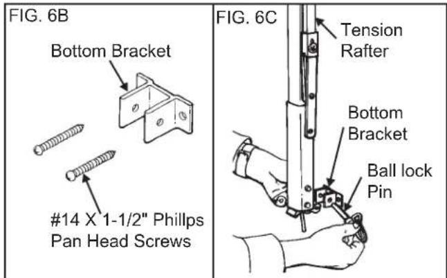
screw placements.
- Detach bottom bracket and predrill two (2) #7 or 3/16" dia. holes.
- Secure bottom bracket with two (2) #14 or 1-1/2" pan head screws with a small dab of silicone sealant on each screw. (See FIG. 6B)
- Attach tension rafter to bottom bracket using
safety spring pin. (See FIG. 6C).
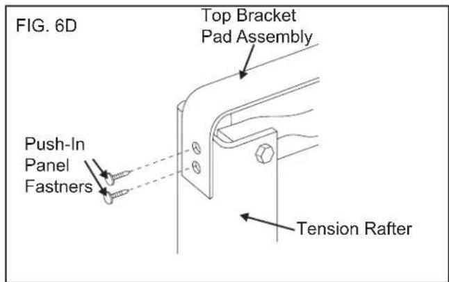
- Attach pad to tension rafter with the supplied push-in panel fasteners. (See FIG. 6D)
NOTE: When installing the tension rafter on a curved vehicle which does not allow for rafter storage, bottom bracket installation is not required.
F. For Use On Awnings With Valance That Hangs From Front Or Bottom Of Roller Tube. (See FIG.7)
- Disconnect tension rafter from bottom bracket and swing it up into position making sure the raf-
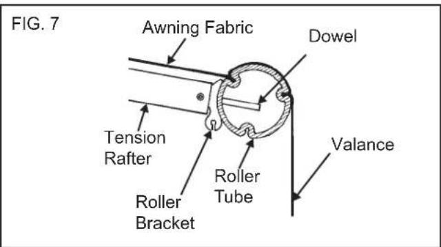
ter is perpendicular to the roller tube.
-
Mark the spot on the roller tube where the dowel of the roller bracket is to be inserted 1-1/4" below the fabric. (See FIG. 7)
-
To prevent damaging the fabric, first center-punch the dowel hole or pilot drill, using a small drill bit.
D. Use a 5/16" dia. bit to drill dowel hole into roller tube.
G. TO TENSION FABRIC:
See "Operating Of Tension Rafter" section A step 6.
H. TO STORE AWNING:
See "Operating Of Tension Rafter" Section B step 5.
CAUTION
DO NOT attempt to close awning until tension rafter is in the correct storage position described in Operating Of Tension Rafter section B Step 5, or damage to the awning may occur.
OPERATING OF TENSION RAFTER
A. To Tenson Fabric
-
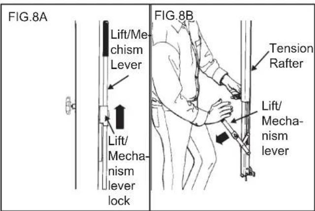
From awning travel position, release pressure on Optima Tension Rafter by sliding lock on lift/tension mechanism lever up and pulling lever forward. (FIGS. 8A & 8B)
-
Roll out awning per awning Operating Instructions.
-
Raise awning roller tube to eye level or a position that is comfortable to reach.
-
Remove the ball lock pin while grasping the bottom section of the tension rafter. Detach the tension rafter and replace pin in bottom bracket. (FIG. 2)
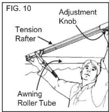
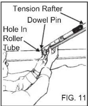
- While raising the tension rafter toward the awning roller tube, loosen the adjusting knob on the left side of the tension rafter. (FIG. 10)
- Extend tension rafter and attach it to awning roller tube by inserting dowel at end of rafter into drilled hole in roller tube. (FIG. 11)
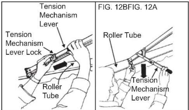
- Slide lock tension mechanism up and pull lever down while holding dowel pin at end of rafter in roller tube. (FIGS. 5A & 5B)
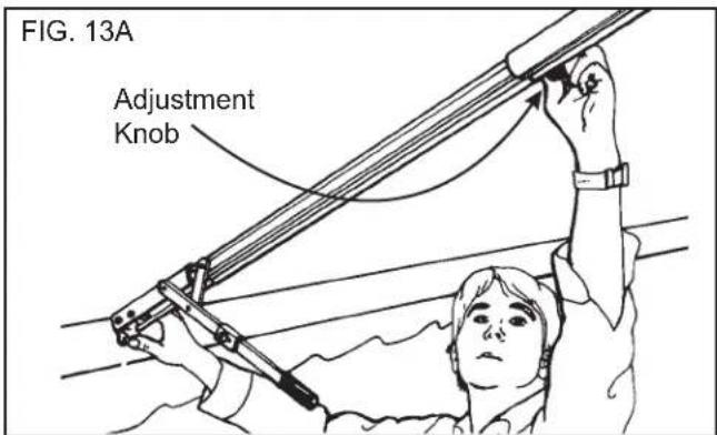
- Firmly tighten adjustment knob on side of tension rafter. (FIG. 13A)
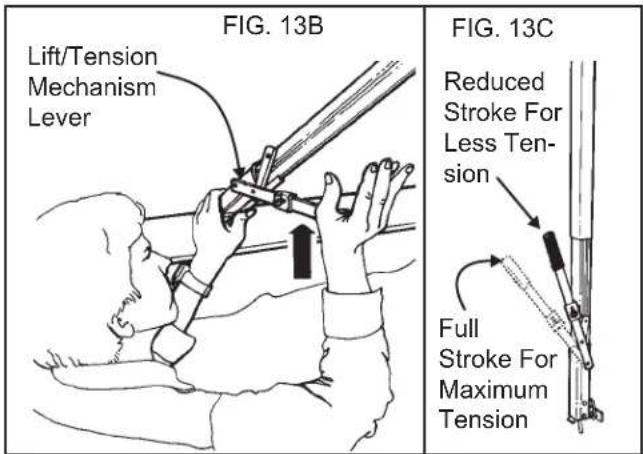
- Grasping the tension mechanism lever, carefully move it up even with the tension rafter and slide the lock over the lever to secure the rafter and slide the lock over the lever to secure the rafter. (FIG. 13B)
This step pushes the roller tube out and stretches the fabric taut. The tension rafter is designed to use the full stroke of the tension mechanism for 25 foot awnings. Shorter awnings may require less tension.
The amount of tension may be lessened by starting with the lever positioned at less of an angle prior to tightening the knob. (FIG. 13C)
- The awning can now be raised to a higher position with no further adjustment to the tension rafter required. If the awning is to be placed into patio position, release the roller tube lock lever before detaching and rotating the awning arms out. This will allow the rafter roller bracket to continue to fit snugly against the roller tube.
B. To Close
WARNING
When used on curved vehicle that does not allow for permanent installation, the tension rafter MUST be removed from the side of Vehicle before traveling.
- Lower the awning. If roller tube lock lever was released, be sure to return to ROLL DOWN POSITION so that the awning will not snap back against the coach when awning rafter arms are released.
-
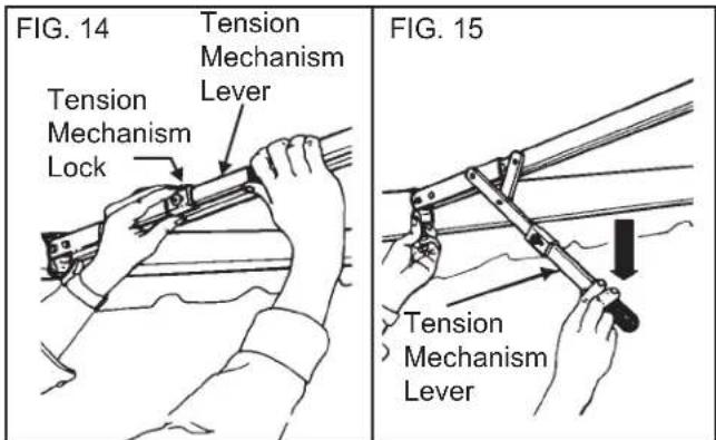
Relieve tension of the tension rafter by unlocking and carefully pulling the tension mechanism lever down. (FIG. 14)
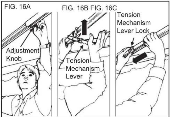
-
Loosen adjustment knob on side of tension rafter and push tension mechanism lever up. Slide tension mechanism lock down. (FIGS. 16A, 16B & 16C)
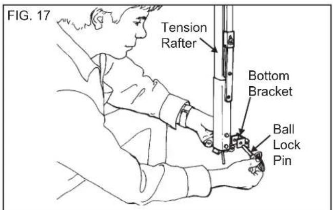
- Remove tension rafter from roller tube and attach to bottom bracket on side of vehicle with ball lock pin. (FIG. 17)
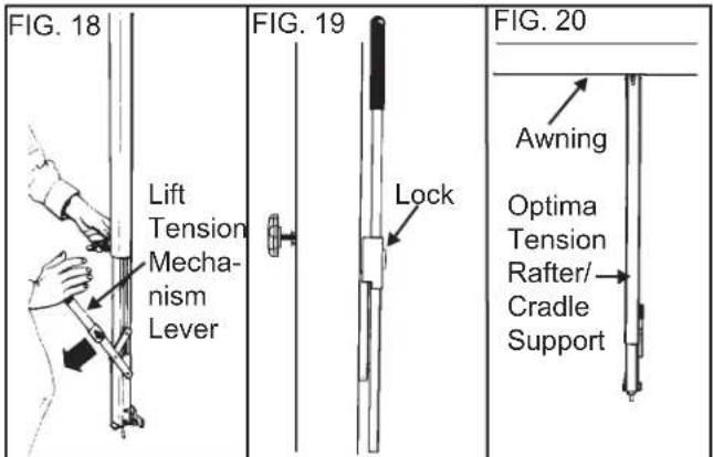
- Slide tension mechanism lock up to unlock lever and pull lever forward. (FIG. 18)
- Close awning per awning Operation Instructions.
- Tighten knob on side of tension rafter and push tension mechanism lever back. This will lift the awning. The amount of lift may be lessened by starting with the lever positioned at less of an angle before tightening the adjustment knob.
- Slide lock on lever down to secure mechanism. Optima Tension Rafter System is now functioning as a cradle support and is ready for travel. (FIGS. 19 & 20)
- A&E Optima Tension Rafter/Cradle Support
- USA
- CANADA
- WARNING
- ! AVERTISSEMENT
- RECOGNIZE SAFETY INFORMATION
- UNDERSTAND SIGNAL WORDS
- in CAUTION
- CAUTION
- A&E OPTIMA TENSION RAFTER SYSTEM
- INSTALLATION INSTRUCTIONS
- INSTALLATION OF TENSION RAFTER
- Tools Required:
- Install Black Adjustment Knob (see FIG.1)
- IMPORTANT: Tension rafter, top cradle, top bracket, and vehicle MUST form right angles as shown in FIG. 3 for tension rafter to operate correctly.
- Bracket/Pad Assembly
- Use Of Backing Support Plate (FIG. 5)
- Tension Rafter Re-Attachment
- Bottom Bracket Installation Postion
- For Use On Awnings With Valance That Hangs From Front Or Bottom Of Roller Tube. (See FIG.7)
- TO TENSION FABRIC:
- TO STORE AWNING:
- OPERATING OF TENSION RAFTER
- To Tenson Fabric
- To Close
Brand : DOMETIC
Model : Optima Plus
Category : Uncategorized