
K8T890-A - Motherboard ECS - Free user manual and instructions
Find the device manual for free K8T890-A ECS in PDF.


| Product Type | Motherboard |
| Brand | ECS (Elitegroup Computer Systems) |
| Model | K8T890-A |
| Form Factor | ATX (305 mm x 211 mm) |
| Processor Socket | Socket 939 |
| Supported Processors | AMD K8 (Athlon 64, Sempron) with HyperTransport up to 2000 MT/s |
| Chipset Northbridge | VIA K8T890 |
| Chipset Southbridge | VIA VT8237 |
| Memory Support | 2 x 184-pin DDR SDRAM, dual-channel, up to 2 GB, DDR400/333/266 |
| Expansion Slots | 1 x PCIe x16, 2 x PCIe x1, 2 x PCI, 1 x AGP Express, 1 x CNR |
| Storage Interfaces | 2 x SATA (RAID 0/1/JBOD), 2 x IDE (UltraDMA 133/100/66), 1 x FDD |
| Audio | AC'97 v2.3 codec, 6-channel (line-in, line-out, mic) |
| LAN | 10/100 Mbps Ethernet (optional) |
| USB Ports | 8 x USB 2.0 (4 rear, 4 via headers) |
| BIOS | AMI BIOS, 93-page manual, PnP, power management |
| Power Connectors | 24-pin ATX, 4-pin +12V (minimum 300W PSU recommended) |
| Rear I/O | PS/2 mouse/keyboard, COM1, LPT1, 4 USB, LAN (optional), audio jacks |
| Internal Headers | Front panel USB/audio, IR, CD-in, speaker, front panel switch/LED |
| Safety & Certifications | FCC Class B, ISO 9001, ISO 14001 |
| Maintenance | Use compressed air for dust; avoid liquids; handle by edges |
| Repairability | Standard ATX; replaceable CPU, RAM, CMOS battery, add-on cards |
Frequently Asked Questions - K8T890-A ECS
User questions about K8T890-A ECS
0 question about this device. Answer the ones you know or ask your own.
Ask a new question about this device
Download the instructions for your Motherboard in PDF format for free! Find your manual K8T890-A - ECS and take your electronic device back in hand. On this page are published all the documents necessary for the use of your device. K8T890-A by ECS.
USER MANUAL K8T890-A ECS
The TÜV CERT Certification Body for QM Systems of RWTÜV Systems GmbH
hereby certifies in accordance with TÜV CERT procedure that
ELITEGROUP COMPUTER SYSTEMS CO., LTD. ECS MANUFACTURING (SHENZHEN) CO., LTD. ELITE TECHNOLOGY (SHENZHEN) CO., LTD.
2F, No. 240, Sec. 1, Nel Hu Road, Taipei, Taiwan 114 No. 22, Alley 38, Lane 91, Sec. 1, Nel Hu Road, Taipei, Taiwan 114 No. 20 & No. 26, Free Trade Zone, Shatoujiao, Shenzhen City, GuangDong Province, China
has established and applies a quality system for
Design, Manufacturing and Sales of Mainboards, Personal Computers, Notebooks and Peripheral Cards
An audit was performed, Report No. 2.5-1585/2000
Proof has been furnished that the requirements according to
ISO 9001 : 2000 / EN ISO 9001 : 2000 / JIS Q 9001 : 2000 / ANSI/ASQC Q9001 : 2000
are fulfilled. The certificate is valid until 27 January 2007
Certificate Registration No. 04100 2000 1325
The company has been certified since 2000
Essen, 04.03.2004



ISO14001
CERTIFICATE
Certificate NO.: 05-2001-065
We hereby certify that
ECS Manufacturing(Shenzhen) Co., Ltd
by reason of its
Environmental Management System
has been awarded this certificate for
compliance with the standard
ISO14001:1996
The Environmental Management System
applies in the following area:
The manufacture of Mother Board and Peripheral Card and interrelated management activities of ECS Manufacturing(Shenzhen) Co.,Ltd.
which is located in No.20, Free Trade Zone, Shatuojiao, Shenzhen, P. R. China.
Date of issue: 30th Dec 2001
Date of expiry: 29th Dec 2004
Signed by:
@2019@2019

SHENZHEN ENVIRONMENTAL MANAGEMENT SYSTEM CERTIFICATION CENTER
Preface

This publication, including all photographs, illustrations and software, is protected under international copyright laws, with all rights reserved. Neither this manual, nor any of the material contained herein, may be reproduced without written consent of the author.
Version 1.0

The information in this document is subject to change without notice. The manufacturer makes no representations or warranties with respect to the contents hereof and specifically disclaims any implied warranties of merchantability or fitness for any particular purpose. The manufacturer reserves the right to revise this publication and to make changes from time to time in the content hereof without obligation of the manufacturer to notify any person of such revision or changes.

Microsoft, MS-DOS and Windows are registered trademarks of Microsoft Corp.
AMD, Athlon, Sempron, and Duron are registered trademarks of AMD Corporation.
Other product names used in this manual are the properties of their respective owners and are acknowledged.

This equipment has been tested and found to comply with the limits for a Class B digital device, pursuant to Part 15 of the FCC Rules. These limits are designed to provide reasonable protection against harmful interference in a residential installation. This equipment generates, uses, and can radiate radio frequency energy and, if not installed and used in accordance with the instructions, may cause harmful interference to radio communications. However, there is no guarantee that interference will not occur in a particular installation. If this equipment does cause harmful interference to radio or television reception, which can be determined by turning the equipment off and on, the user is encouraged to try to correct the interference by one or more of the following measures:
- Reorient or relocate the receiving antenna.
- Increase the separation between the equipment and the receiver.
- Connect the equipment onto an outlet on a circuit different from that to which the receiver is connected.
- Consult the dealer or an experienced radio/TV technician for help.
Shielded interconnect cables and a shielded AC power cable must be employed with this equipment to ensure compliance with the pertinent RF emission limits governing this device. Changes or modifications not expressly approved by the system's manufacturer could void the user's authority to operate the equipment.

This device complies with part 15 of the FCC rules. Operation is subject to the following conditions:
• This device may not cause harmful interference, and
- This device must accept any interference received, including interference that may cause undesired operation.

This class B digital apparatus meets all requirements of the Canadian Interference-causing Equipment Regulations.
The manual consists of the following:
Chapter 1
| Introducing the Motherboard | Describes features of the motherboard. |
Go to → page 1
Chapter 2
| Installing the Motherboard | components. |
Go to → page 7
Chapter 3
| Using BIOS | Setup Utility. |
Go to → page 27
Chapter 4
| Using the Motherboard Software | Go to | → | page 41 |
Go to → page 41
Chapter 5
| VIA VT8237 SATA RAID Setup Guide | Setup |
Go to → page 45
Preface i
◆◆◆□▼◆◆
Introducing the Motherboard 1
Introduction....1
Features....2
Motherboard Components....4
÷ 米□▼米□ ✗
Installing the Motherboard 7
Safety Precautions....7
Choosing a Computer Case....7
Installing the Motherboard in a Case....7
Checking Jumper Settings....8
Setting Jumpers....8
Checking Jumper Settings....9
Jumper Settings....9
Connecting Case Components....10
Front Panel Header....12
Installing Hardware....13
Installing the Processor....13
Installing Memory Modules....14
Installing a Hard Disk Drive/CD-ROM/SATA Hard Drive......18
Installing a Floppy Diskette Drive....20
Installing Add-on Cards....21
Connecting Optional Devices....24
Connecting I/O Devices....26
÷° ××
Using BIOS 27
About the Setup Utility....27
The Standard Configuration....27
Entering the Setup Utility....27
Updating the BIOS....29
Using BIOS....29
Standard CMOS Setup....30
Advanced Setup....31
Features Setup....33
Power Management Setup....34
PCI/Plug and Play Setup....36
BIOS Security Features....37
CPU PnP Setup....38
Hardware Monitor....39
Load Optimal Defaults....40
Save Changes and Exit....40
Discard Changes and Exit....40
…□□√
√⊗ √∞
Using the Motherboard Software 41
About the Software CD-ROM....41
Auto-installing under Windows 98/ME/2000/XP....41
Running Setup....42
Manual Installation....44
Utility Software Reference....44
◆◆◆◆◆◆◆◆◆◆◆◆◆◆◆◆◆◆◆◆◆◆◆◆◆◆◆◆◆◆◆◆◆◆◆◆◆◆◆◆◆◆◆◆◆◆◆◆◆◆◆◆◆◆◆◆◆◆◆◆◆◆◆◆◆◆◆◆◆◆◆◆◆◆◆◆◆◆◆◆◆◆◆◆◆◆◆◆◆◆◆◆◆◆◆◆◆◆◆◆ ◆ ◆ ◆ ◆ ◆ ◆ ◆ ◆ ◆ ◆ ◆ ◆ ◆ ◆ ◆ ◆ ◆ ◆ ◆ ◆ ◆ ◆ ◆ ◆ ◆ ◆ ◆ ◆ ◆ ◆ ◆ ◆ ◆ ◆ ◆ ◆ ◆ ◆ ◆ ◆ ◆ ◆ ◆ ◆ ◆ ◆ ◆ ◆ ◆ ◆ ◉
√× √×
VIA VT8237 SATA RAID Setup Guide
45
VIA RAID Configurations....45
Installing RAID Software & Drives....52
Using VIA RAID Tool....54
Multi-Language Translation
Introduction
Thank you for choosing K8T890-A motherboard of great performance and with enhanced function. The K8T890-A is designed to fit the AMD K8 processors in the 939-pin package. Based on the ATX form factor, measuring 305mm× 211mm , this motherboard incorporates the following chipsets: K8T890 Northbridge and VT8237 Southbridge chipsets.
The K8T890 Northbridge features the HyperTransport Technology to transfer of 2000MT/s, 1600 MT/s, 1200 MT/s, 800 MT/s or 400 MT/s each direction simultaneously, providing a total maximum data transfer bandwidth of 8 GB/sec. Two 184 pin unbuffered DDR SDRAM DIMM sockets support up to 2 GB in total memory. Aside from the onboard AGP Express slot, one PCI Express x16 slot, intended for Graphics interface, is fully compliant to the PCI Express Base Specification revision 1.0a. The K8T890 Northbridge interconnects to the South Bridge through the high speed 8x 66 MHz (533 MB/sec) V-Link interface.
The VT8237 Southbridge is a highly integrated peripheral controller, it includes an integrated keyboard controller with PS2 mouse support, two-channel Serial ATA/RAID hard disk controller, master mode enhanced Parallel IDE controller with full scatter/gather capability and extension to UltraDMA-133/100/66 for 133/100/66 MB/sec transfer rate, integrated USB 2.0 interface supporting up to 8 USB 2.0 ports. The VT8237 features outstanding expansion capability such as, five PCI slots with PCI v2.2 compliant. The VT8237 integrated Fast Ethernet controller with standard MII interface to an external PHY for 10/100Mb Base-T Ethernet, as well as AC'97 audio codec compliant.
There is an advanced full set of I/O ports in the rear panel, including PS/2 mouse and keyboard connectors, COM1, LPT1, four USB ports at the rear I/O, one LAN port (optional), and audio jacks for microphone, line-in, and line-out.
Feature
Processor
K8T890-A uses a 939-pin socket that carries the following features:
• Supports AMD K8 processors with HyperTransport Technology
• Transfer rate of 2000/1600/1200/800/400 MT/s
HyperTransport Technology is a point-to-point link between two devices, it enables integrated circuits to exchange information at much higher speeds than currently available interconnect technologies.
Chipset
The VIA K8T890 Northbridge (NB) and VIA VT8237 Southbridge (SB) chipset is based on an innovative and scalable architecture with proven reliability and performance.
K8T890 (NB)
- 1000/800/600/400/200 MHz clock rates with Double Data Rate-style operation for 2000/1600/1200/800/400 MT/s in both directions simultaneously
• Supports 66 MHz, 8x/4x transfer modes, Ultra V-Link Host interface with 1 GB/s total bandwidth
• Supports asynchronous interface between HyperTransport and PCI Express - Compliant with advanced high bandwidth PCI Express 1.0a
VT8237 (SB)
• Supports 16-bit 66 MHz V-Link Host interface with total bandwidth of 1066 MB/s
- Compliant with PCI 2.2 specification at 33 MHz, supporting up to 6 PCI masters
- Integrated Dual channel UltraDMA 133/100/66 Master Mode EIDE Controller
• USB 2.0 Controller, supporting for 8 USB 2.0 ports
- Integrated keyboard Controller with PS2 mouse support
Memory
• Supports DDR400/333/266 memory types with Dual-channel architecture
- Accommodates two unbuffered 2.5V 184-pin DDR SDRAM DIMM sockets
• A total maximum capacity 2 GB
Audio CODEC
- Meets Microsoft WHQL/WLP 2.0 audio requirements
- Compliant with AC'97 v2.3 specification
• High quality differential CD input
• Supports double sampling rate (96KHz) of DVD audio playback - Direct Sound 3D TM compatible
Onboard LAN (optional)
The onboard LAN provides the following features:
• Dual speed -- 100/10 Mbps
- MII interface to ethernet controller
• Auto negotiation: 10/100, Full/Half Duplex
- Meet all applicable IEEE 802.3, 10Base-T and 100Base-Tx standards
Expansion Options
The motherboard comes with the following expansion options:
• One PCI Express x16 slot
- Two PCI Express x1 slots
- Two 32-bit PCI slots
• One AGP Express slot
- Two IDE connectors which support four IDE devices
• One floppy disk drive interface
- Two 7-pin SATA connectors
• One Communications Networking Riser (CNR) slot
This motherboard supports Ultra DMA bus mastering with transfer rates of 133/100/66 MB/s.
Integrated I/O
The motherboard has a full set of I/O ports and connectors:
- Two PS/2 ports for mouse and keyboard
- One serial port
- One parallel port
• Eight USB ports (rear panel x 4, header x 4)
• One LAN port (optional)
• Audio jacks for microphone, line-in and line-out
BIOS Firmware
The motherboard uses AMI BIOS that enables users to configure many system features including the following:
• Power management
- Wake-up alarms
- CPU parameters
• CPU and memory timing
The firmware can also be used to set parameters for different processor clock speeds.

Some hardware specifications and software items are subject to change without prior notice.

Motherboard Components

Table of Motherboard Components
| LABEL | COMPONENT |
| 1 CPU Socket Socket 939 for AMD K8 processor | |
| 2 CPU_FAN1 | CPU cooling fan connector |
| 3 DIMM1~2 184-pin DDR SDRAM slots | |
| 4 USB2~3 | Front Panel USB headers |
| 5 SATA1~SATA2 Serial ATA connectors | |
| 6 IDE1 Primary IDE connector | |
| 7 IDE2 Secondary IDE connector | |
| 8 SYS_FAN1 | System cooling fan connector |
| 9 JCMOS1 Clear CMOS jumper | |
| 10 SPK1 | Speaker header |
| 11 PANEL1 Front panel switch/LED header | |
| 12 SIR1 Infrared header | |
| 13 FDD1 Floppy disk drive connector | |
| 14 CNR1 Communications Networking Riser slot | |
| 15 PCI1~2 | 32-bit add-on card slots |
| 16 AGPRO1 AGP Express graphics card slot | |
| 17 PCI-E2~3 PCI Express x1 Slots | |
| 18 CD1 CD-in header | |
| 19 PCI-E1 | PCI Express x16 Slot |
| 20 AUDIO2 Front panel audio header | |
| 21 PWR1 Standard 24-pin ATX power connector | |
| 22 NB_FAN* | Northbridge cooling fan connector |
| 23 PWR2 4-pin +12V power connector | |
“>” stands for optional components and may not exist onboard.
This concludes Chapter 1. The next chapter explains how to install the motherboard.
×
★★○□
Safety Precautions
- Follow these safety precautions when installing the motherboard
- Wear a grounding strap attached to a grounded device to avoid damage from static electricity
- Discharge static electricity by touching the metal case of a safely grounded object before working on the motherboard
- Leave components in the static-proof bags they came in
- Hold all circuit boards by the edges. Do not bend circuit boards
Choosing a Computer Case
There are many types of computer cases on the market. The motherboard complies with the specifications for the ATX system case. First, some features on the motherboard are implemented by cabling connectors on the motherboard to indicators and switches on the system case. Make sure that your case supports all the features required. Secondly, K8T890-A supports one or two floppy diskette drives and four enhanced IDE drives. Make sure that your case has sufficient power and space for all drives that you intend to install.
Most cases have a choice of I/O templates in the rear panel. Make sure that the I/O template in the case matches the I/O ports installed on the rear edge of the motherboard.
This motherboard carries an ATX form factor of 305 X 211 mm. Choose a case that accommodates this form factor.
Installing the Motherboard in a Case
Refer to the following illustration and instructions for installing the motherboard in a case.
Most system cases have mounting brackets installed in the case, which correspond the holes in the motherboard. Place the motherboard over the mounting brackets and secure the motherboard onto the mounting brackets with screws.
Ensure that your case has an I/O template that supports the I/O ports and expansion slots on your motherboard.


Do not over-tighten the screws as this can stress the motherboard.
Checking Jumper Settings
This section explains how to set jumpers for correct configuration of the motherboard.
Setting Jumpers
Use the motherboard jumpers to set system configuration options. Jumpers with more than one pin are numbered. When setting the jumpers, ensure that the jumper caps are placed on the correct pins.
The illustrations show a 2-pin jumper. When the jumper cap is placed on both pins, the jumper is SHORT. If you remove the jumper cap, or place the jumper cap on just one pin, the jumper is OPEN.
This illustration shows a 3-pin jumper. Pins 1 and 2 are SHORT

SHORT

OPEN

Checking Jumper Settings
The following illustration shows the location of the motherboard jumpers. Pin 1 is labeled.
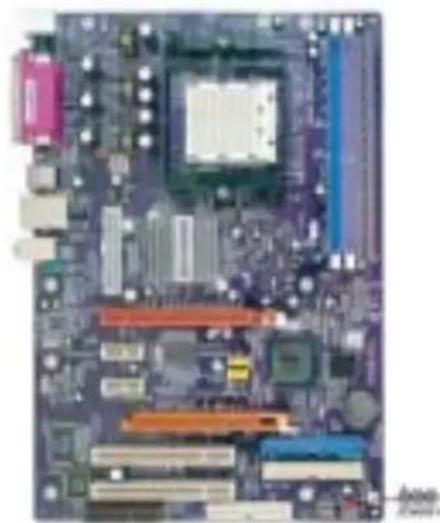
Jumper Settings
| Jumper | Type | Description | Setting (default) | |
| JCMOS1 | 3-pin | CLEAR CMOS | 1-2: NORMAL2-3: CLEARBefore clearing the CMOS, make sure to turn the sys-tem off. | JCMOS1 |
Connecting Case Components
After you have installed the motherboard into a case, you can begin connecting the motherboard components. Refer to the following:
1 Connect the CPU cooling fan cable to CPU_FAN1.
2 Connect the Northbridge cooling fan cable NB_FAN.
3 Connect the system cooling fan connector to SYS_FAN1.
4 Connect the case speaker cable to SPK1
5 Connect the case switches and indicator LEDs to the PANEL1.
6 Connect the standard power supply connector to PWR1.
7 Connect the auxiliary case power supply connector to PWR2.

Connecting 20/24-pin power cable
Users please note that the 20-pin and 24-pin power cables can both be connected to the ATX1 connector. With the 20-pin power cable, just align the 20-pin power cable with the pin 1 of the ATX1 connector. However, using 20-pin power cable may cause the system to become unbootable or unstable because of insufficient electricity. A minimum power of 300W is recommended for a fully-configured system.

20-pin power cable
Users please note that when installing 20-pin power cable, the latche of power cable falls on the left side of the PWR1 connector latch, just as the picture shows.

Users please note that when installing 24-pin power cable, the latches of power cable falls on the right side of PWR1 connector latch.
24-pin power cable
CPU_FAN1/SYS_FAN1/NB_FAN: FAN Power Connectors
| Pin Signal Name Function | ||
| 1 GND System Ground | ||
| 2 | +12V Power +12V | |
| 3 | Sense Sensor | |
PWR1: ATX 24-pin Power Connector
| Pin | Signal Name | Pin | Signal Name |
| 1 +3.3V 13 +3.3V | |||
| 2 +3.3V 14 -12V | |||
| 3 Ground 15 COM | |||
| 4 +5V 16 PS_ON | |||
| 5 Ground 17 COM | |||
| 6 +5V 18 COM | |||
| 7 Ground 19 COM | |||
| 8 PWRGD 20 -5V | |||
| 9 +5VSB 21 +5V | |||
| 10 | +12V | 22 | +5V |
| 11 | +12V | 23 | +5V |
| 12 | +3.3V | 24 | COM |
PWR2: ATX 12V Power Connector
| Pin Signal Name | |
| 1 | Ground |
| 2 | Ground |
| 3 | +12V |
| 4 | +12V |
SPK1: Internal speaker
| Pin Signal Name | |
| 1 | VCC |
| 2 | Key |
| 3 | GND |
| 4 | Signal |
Front Panel Header
The front panel connector (PANEL1) provides a standard set of switch and LED header commonly found on ATX or micro-ATX cases. Refer to the table below for information:

PANEL1
| Pin | Signal Name | Function | Pin | Signal Name | Function |
| 1 | HD_LED_P | Hard disk LED(+) | 2 | FP PWR/SLP | *MSG LED(+) |
| 3 | HD_LED_N | Hard disk LED(-) | 4 | FP PWR/SLP | *MSG LED(-) |
| 5 | RST_SW_N | Reset Switch(-) | 6 | PWR_SW_P | Power Switch(+) |
| 7 | RST_SW_P | Reset Switch(+) | 8 | PWR_SW_N | Power Switch(-) |
| 9 | RSVD Reserved | 10 | Key No pin |
*MSG LED (dual color or single color)
Hard Drive Activity LED
Connecting pins 1 and 3 to a front panel mounted LED provides visual indication that data is being read from or written to the hard drive. For the LED to function properly, an IDE drive should be connected to the onboard IDE interface. The LED will also show activity for devices connected to the SCSI (hard drive activity LED) connector.
Power/Sleep/Message waiting LED
Connecting pins 2 and 4 to a single or dual-color, front panel mounted LED provides power on/off, sleep, and message waiting indication.
Reset Switch
Supporting the reset function requires connecting pin 5 and 7 to a momentary-contact switch that is normally open. When the switch is closed, the board resets and runs POST.
Power Switch
Supporting the power on/off function requires connecting pins 6 and 8 to a momentary-contact switch that is normally open. The switch should maintain contact for at least 50 ms to signal the power supply to switch on or off. The time requirement is due to internal debounce circuitry. After receiving a power on/off signal, at least two seconds elapses before the power supply recognizes another on/off signal.
Installing Hardware
Installing the Processor

Caution: When installing a CPU heatsink and cooling fan make sure that you DO NOT scratch the motherboard or any of the surface-mount resistors with the clip of the cooling fan. If the clip of the cooling fan scrapes across the motherboard, you may cause serious damage to the motherboard or its components.
On most motherboards, there are small surface-mount resistors near the processor socket, which may be damaged if the cooling fan is carelessly installed.
Avoid using cooling fans with sharp edges on the fan casing and the clips. Also, install the cooling fan in a well-lit work area so that you can clearly see the motherboard and processor socket.
Before installing the Processor
This motherboard automatically determines the CPU clock frequency and system bus frequency for the processor. You may be able to change these settings by changing the settings in the system Setup Utility. We strongly recommend that you do not over-clock processors or other components to run faster than their rated speed.

Warning: Over-clocking components can adversely affect the reliability of the system and introduce errors into your system. Over-clocking can permanently damage the motherboard by generating excess heat in components that are run beyond the rated limits.
This motherboard has a Socket 939 processor socket. When choosing a processor, consider the performance requirements of the system. Performance is based on the processor design, the clock speed and system bus frequency of the processor, and the quantity of internal cache memory and external cache memory.
CPU Installation Procedure
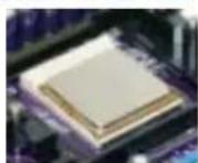
The following illustration shows CPU installation components.
1 Install your CPU. Pull up the lever away from the socket and lift up to 90-degree angle.
2 Locate the CPU cut edge (the corner with the pin hold noticeably missing). Align and insert the CPU correctly.
3 Press the lever down and apply thermal grease on top of the CPU.
4 Put the CPU Fan down on the retention module and snap the four retention legs of the cooling fan into place.
5 Flip the levers over to lock the heat sink in place and connect the CPU cooling Fan power cable to the CPUFAN connector. This completes the installation.

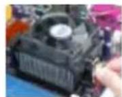

To achieve better airflow rates and heat dissipation, we suggest that you use a high quality fan with 4800 rpm at least. CPU fan and heatsink installation procedures may vary with the type of CPU fan/heatsink supplied. The form and size of fan/heatsink may also vary.
Installing Memory Modules
K8T890-A accommodates two 184-pin 2.5V unbuffered Double Data Rate (DDR) SDRAM (Synchronous Dynamic Random Access Memory) memory modules. K8T890-A can support DDR400/333/266 memory types and its total maximum memory size is 2 GB.
DDR SDRAM memory module table
| Memory module Memory Bus | |
| DDR266 133MHz | |
| DDR333 166MHz | |
| DDR400 200MHz | |

Do not remove any memory module from its antistatic packaging until you are ready to install it on the motherboard. Handle the modules only by their edges. Do not touch the components or metal parts. Always wear a grounding strap when you handle the modules.
Notes:
- When running dual channel mode, install only same (same density, DRAM technology and DRAM bus width) module for each deal channel.
- Please note that those types not in the Table B (p.16) will not boot up.
Installation Procedure
Refer to the following to install the memory modules.
1 This motherboard supports unbuffered DDR SDRAM only.
2 Push the latches on each side of the DIMM slot down.
3 Align the memory module with the slot. The DIMM slots are keyed with notches and the DIMMs are keyed with cutouts so that they can only be installed correctly.
4 Check that the cutouts on the DIMM module edge connector match the notches in the DIMM slot.
5 Install the DIMM module into the slot and press it firmly down until it seats correctly. The slot latches are levered upwards and latch on to the edges of the DIMM.

Table A: DDR (memory module) QVL (Qualified Vendor List)
The following DDR400 memory modules have been tested and qualified for use with this motherboard.
| Size Vendor Model | Name | |
| 256MB | A-DATA | ADD8608A8A-4.5B |
| A-DATA | ADD8608A8A-5B | |
| Apacer | AM3A568ACT-5A | |
| GEIL | G208L364D1TG5NKT3C | |
| GEIL | GE08L3264D1WL5NKT3H71 | |
| GEIL | GE08L3264DTWL5NKT3H710902 | |
| Hynix | HY5DU5656822BT-D43 | |
| Hynix | HY5DU56822BT-D43 | |
| KingMax | KDL388P4EA-50A | |
| Kingston | D3208DL2T-5 0323PT | |
| Ramaxel | MT-46V32M8 TG-5 | |
| SAMSUNG | K4H560838D-TCC4 | |
| SAMSUNG | K4H560838D-TCCC | |
| TwinMOS | TMD7608F8E50D | |
| Winbond | W942508BH-5 | |
| 512MB | CORSAIR | CMX512-3200C2PT |
| CORSAIR | CMX512-3500C2PT | |
| CORSAIR | CMX512-4400PT | |
| Hynix | HY5DU56822DT-D5 | |
| Infineon | HYB25D256800BT-5 | |
| Kingston | D3208DL1T-5 | |
| Kingston | KHX3500AK2 | |
| Mushkin PC3500 level ONE | ||
| PSC | A2S56D30BTP | |
| SAMSUNG | K4H560838E-TCCC | |
| SAMSUNG | K4H560838D-TCC4 | |
| Transcend | V58C2256804SAT5B | |
| UNIFOSA | USI 64M8B8-WB200-04 | |
| ValueSelect | VS32MB-5 2B0402 | |
| 1GB | CORSAIR | CMX1024-3200PT |
Table B: Unbuffered DIMM Support for 939-pin
| Data Bus | Chip Selects | Maximum DRAM Speed | ||||
| MEMCS_1L_L* | MEMCS_2H_L* | MEMCS_2L_L* | MEMCS_2H_L* | 1T 2T | ||
| 64-bits | Single rank | N/A | N/A | N/A | DDR400 | DDR400 |
| Double rank | N/A | N/A | N/A | DDR400 | DDR400 | |
| N/A | N/A | Single rank | N/A | DDR400 | DDR400 | |
| N/A | N/A | Double rank | N/A | DDR400 | DDR400 | |
| Single rank | N/A | Single rank | N/A | DDR333 | DDR400 | |
| Single rank | N/A | Double rank | N/A | DDR200 | DDR400 | |
| Double rank | N/A | Single rank | N/A | DDR200 | DDR400 | |
| Double rank | N/A | Double rank | N/A | DDR200 | DDR333 | |
| 128-bits | Single rank | Single rank | N/A | N/A | DDR400 | DDR400 |
| Double rank | Double rank | N/A | N/A | DDR400 | DDR400 | |
| N/A | N/A | Single rank | Single rank | DDR400 | DDR400 | |
| N/A | N/A | Double rank | Double rank | DDR400 | DDR400 | |
| Single rank | Single rank | Single rank | Single rank | DDR333 | DDR400 | |
| Single rank | Single rank | Double rank | Double rank | DDR200 | DDR400 | |
| Double rank | Double rank | Single rank | Single rank | DDR200 | DDR400 | |
| Double rank | Double rank | Double rank | Double rank | DDR200 | DDR333 | |
Note for “*”: Memory types must be set to values consistent with system hardware.
Installing a Hard Disk Drive/CD-ROM/SATA Hard Drive
This section describes how to install IDE devices such as a hard disk drive and a CD-ROM drive.
About IDE Devices
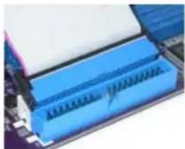
Your motherboard has a primary and secondary IDE channel interface (IDE1 and IDE2). An IDE ribbon cable supporting two IDE devices is bundled with the motherboard.

You must orient the cable connector so that the pin1 (color) edge of the cable corresponds to the pin 1 of the I/O port connector.
IDE1: Primary IDE Connector
The first hard drive should always be connected to IDE1.

IDE2: Secondary IDE Connector
The second drive on this controller must be set to slave mode. The configuration is the same as IDE1.

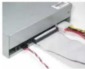
IDE devices enclose jumpers or switches used to set the IDE device as MASTER or SLAVE. Refer to the IDE device user's manual. Installing two IDE devices on one cable, ensure that one device is set to MASTER and the other device is set to SLAVE. The documentation of your IDE device explains how to do this.
About UltraDMA
This motherboard supports UltraDMA 133/100/66. UDMA is a technology that accelerates the performance of devices in the IDE channel. To maximize performance, install IDE devices that support UDMA and use 80-pin IDE cables that support UDMA 133/100/66.
About SATA Connectors
Your motherboard features two SATA connectors supporting a total of two drives. SATA refers to Serial ATA (Advanced Technology Attachment) is the standard interface for the IDE hard drives which are currently used in most PCs. These connectors are well designed and will only fit in one orientation. Locate the SATA connectors on the motherboard (see page 21) and follow the illustration below to install the SATA hard drives.
Installing Serial ATA Hard Drives
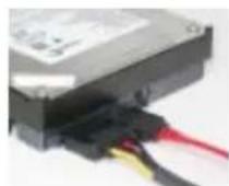
To install the Serial ATA (SATA) hard drives, use the SATA cable that supports the Serial ATA protocol. This SATA cable comes with an SATA power cable. You can connect either end of the SATA cable to the SATA hard drive or the connector on the motherboard.

SATA cable (optional)

SATA power cable (optional)
Refer to the illustration below for proper installation:
1 Attach either cable end to the connector on the motherboard.
2 Attach the other cable end to the SATA hard drive.
3 Attach the SATA power cable to the SATA hard drive and connect the other end to the power supply.


This motherboard does not support the "Hot-Plug" function.
Installing a Floppy Diskette Drive
The motherboard has a floppy diskette drive (FDD) interface and ships with a diskette drive ribbon cable that supports one or two floppy diskette drives. You can install a 5.25-inch drive and a 3.5-inch drive with various capacities. The floppy diskette drive cable has one type of connector for a 5.25-inch drive and another type of connector for a 3.5-inch drive.

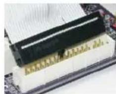
You must orient the cable connector so that the pin 1 (color) edge of the cable corresponds to the pin 1 of the I/O port connector.
FDD1: Floppy Disk Connector
This connector supports the provided floppy drive ribbon cable. After connecting the single end to the onboard floppy connector, connect the remaining plugs on the other end to the floppy drives correspondingly.
Installing Add-on Cards
The slots on this motherboard are designed to hold expansion cards and connect them to the system bus. Expansion slots are a means of adding or enhancing the motherboard's features and capabilities. With these efficient facilities, you can increase the motherboard's capabilities by adding hardware that performs tasks that are not part of the basic system.

PCI-E1 Slot The PCI Express x16 slot is fully compliant to the PCI Express Base Specification revision 1.0a.
PCI-E2\~3 The two PCI Express x1 slots are fully compliant to the PCI Express Base Slots Specification revision 1.0a.
AGPRO1 The AGP Express slot is used to install an AGP graphics card that emulates the AGP function. To get better performance and compatibility on our special designed AGPRO slot, we recommend users use one of the AGP graphics cards that have been tested by our company. See the "AGP Express Graphics Cards Support List" or visit our website at "http://www.ccs.com.tw" for the updated support list.
PCI Slots This motherboard is equipped with two standard PCI slots. PCI stands for Peripheral Component Interconnect and is a bus standard for expansion cards, which for the most part, is a supplement of the older ISA bus standard. The PCI slots on this board are PCI v2.2 compliant.
CNR Slots This slot is used to insert CNR card with Modem and Audio functionality.

Before installing an add-on card, check the documentation for the card carefully. If the card is not Plug and Play, you may have to manually configure the card before installation.
Follow these instructions to install an add-on card:
1 Remove a blanking plate from the system case corresponding to the slot you are going to use.
2 Install the edge connector of the add-on card into the expansion slot. Ensure that the edge connector is correctly seated in the slot.
3 Secure the metal bracket of the card to the system case with a screw.
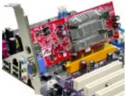

For some add-on cards, for example graphics adapters and network adapters, you have to install drivers and software before you can begin using the add-on card.
Table A: AGP Express Graphics Cards Support List
| VGA Chip | Model name AGP | |
| nVIDIA | ASUS AGP-V7100 | 4X |
| ASUS V8200 | ||
| ASUS V8170DDR | ||
| ELSA GLADIAC GTS DDR PRO/64M | ||
| ELSA GLADIAC MX | ||
| ELSA GLADIAC 725DVI | ||
| ELSA GLADIAC 925ViVo | ||
| GIGABYTE GV-GF2010D | ||
| WINFAST S325 TNT M64 | ||
| WINFAST GeForce 2 Ultra | ||
| WINFAST A250TD/64M | ||
| ASUS V9280TD | 8X | |
| ELSA GLADIAC FX935 | ||
| ELSA GLADIAC FX938Ultra | ||
| ELSA GLADIAC FX 736 | ||
| MSI Geforce4 Titanium4200 | ||
| MSI FX5900U-VTD256 | ||
| WINFAST A350TDH | ||
| ATI | ATI RADEON 8500 DDR | 4X |
| ECS R9200LE- 64M | ||
| ECS R9200LE- 128M | 8X | |
| ECS R9250-128T | ||
| GIGABYET GV-R9000PRO | ||
| Power Color Radeon9500 | ||
| SIS | ECS AG200E4-D32 | 8X |
| ECS AG200T8_D64 | ||
| ECS AG400T8_D64 | ||
| ECS-MM AG400T8_D64 |

For the latest updates of the supported AGP VGA cards list, please visit ECS ELITEGROUP website for details.
ECS ELITEGROUP website: http://www.ecs.com.tw
Connecting Optional Devices
Refer to the following for information on connecting the motherboard's optional devices:
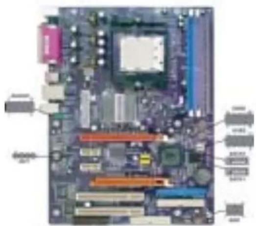
AUDIO2: Front Panel Audio header
This header allows the user to install auxiliary front-oriented microphone and line-out ports for easier access.
| Pin Signal Name Function | ||
| 1 AUD_MIC Front Panel Microphone input signal | ||
| 2 AUD_GND Ground used by Analog Audio Circuits | ||
| 3 AUD_MIC_BIAS Microphone Power | ||
| 4 AUD_VCC Filtered +5V used by Analog Audio Circuits | ||
| 5 AUD_F_R Right Channel audio signal to Front Panel | ||
| 6 | AUD_RET_R | RightChannelAudio signal to Return from FrontPanel |
| 7 REVD Reserved | ||
| 8 Key No Pin | ||
| 9 AUD_F_L Left Channel Audio signal to Front Panel | ||
| 10 | AUD_RET_L | Left ChannelAudio signal to Return from Front Panel |
CD1: CD Audio Input header
| Pin Signal Name Function | |
| 1 CD in_L CD In left channel | |
| 2 GND | Ground |
| 3 GND | Ground |
| 4 CD in_R CD In right channel | |
USB2\~3: Front Panel USB headers
The motherboard has four USB ports installed on the rear edge I/O port array. Additionally, some computer cases have USB ports at the front of the case. If you have this kind of case, use auxiliary USB connector to connect the front-mounted ports to the motherboard.
| Pin Signal Name Function | |
| 1 USBPWR Front Panel | USB Power |
| 2 USBPWR Front Panel | USB Power |
| 3 USB_FP_P0- USB Port 0 | Negative Signal |
| 4 USB_FP_P1- USB Port 1 | Negative Signal |
| 5 USB_FP_P0+ USB Port 0 | Positive Signal |
| 6 USB_FP_P1+ USB Port 1 | Positive Signal |
| 7 GND Ground | |
| 8 GND Ground | |
| 9 Key No pin | |
| 10 USB_FP_OC0 Overcurrent signal | |

Please make sure that the USB cable has the same pin assignment as indicated above. A different pin assignment may cause damage or system hang-up.
SATA1\~2: Serial ATA connectors
These connectors are use to support the new Serial ATA devices for the highest date transfer rates (150 MB/s), simpler disk drive cabling and easier PC assembly. It eliminates limitations of the current Parallel ATA interface. But maintains register compatibility and software compatibility with Parallel ATA.
| Pin Signal Name Pin Signal Name | |
| 1 Ground 2 TX+ | |
| 3 TX-4 Ground | |
| 5 RX-6 RX+ | |
| 7 Ground - - | |
SIR1: Infrared header
The mainboard supports an Infrared (SIR1) data port. Infrared port allows the wireless exchange of information between your computer and similarly equipped devices such as printers, laptops, Personal Digital Assistants (PDAs), cell phones, and other computers.
| Pin | Signal Name | Function |
| 1 Not | Assigned Not assigned | |
| 2 Key | No pin | |
| 3 +5V | IR Power | |
| 4 GND | Ground | |
| 5 | IRTX | IrDA serial output |
| 6 | IRTX | IrDA serial input |
Connecting I/O Devices
The backplane of the motherboard has the following I/O ports:
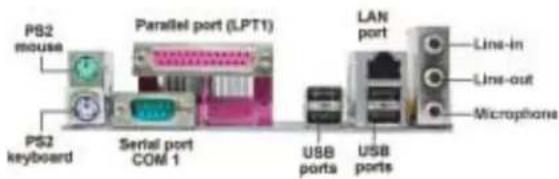
PS2 Mouse Use the upper PS/2 port to connect a PS/2 pointing device.
PS2 Keyboard Use the lower PS/2 port to connect a PS/2 keyboard.
Parallel Port (LPT1) Use LPT1 to connect printers or other parallel communications devices.
Serial Port Use the COM port to connect serial devices such as mice or (COM1) fax/modems.
LAN Port (optional) Connect an RJ-45 jack to the LAN port to connect your computer to the Network.
USB Ports Use the USB ports to connect USB devices.
Audio Ports Use the three audio ports to connect audio devices. The first jack is for stereo line-in signal. The second jack is for stereo line-out signal. The third jack is for microphone.
This concludes Chapter 2. The next chapter covers the BIOS.
About the Setup Utility
The computer uses the latest American Megatrends BIOS with support for Windows Plug and Play. The CMOS chip on the motherboard contains the ROM setup instructions for configuring the motherboard BIOS.
The BIOS (Basic Input and Output System) Setup Utility displays the system's configuration status and provides you with options to set system parameters. The parameters are stored in battery-backed-up CMOS RAM that saves this information when the power is turned off. When the system is turned back on, the system is configured with the values you stored in CMOS.
The BIOS Setup Utility enables you to configure:
- Hard drives, diskette drives and peripherals
• Video display type and display options - Password protection from unauthorized use
• Power Management features
The settings made in the Setup Utility affect how the computer performs. Before using the Setup Utility, ensure that you understand the Setup Utility options.
This chapter provides explanations for Setup Utility options.
The Standard Configuration
A standard configuration has already been set in the Setup Utility. However, we recommend that you read this chapter in case you need to make any changes in the future.
This Setup Utility should be used:
- when changing the system configuration
- when a configuration error is detected and you are prompted to make changes to the Setup Utility
- when trying to resolve IRQ conflicts
- when making changes to the Power Management configuration
- when changing the password or making other changes to the Security Setup
Entering the Setup Utility
When you power on the system, BIOS enters the Power-On Self Test (POST) routines. POST is a series of built-in diagnostics performed by the BIOS. After the POST routines are completed, the following message appears:
Press DEL/F1 to enter SETUP
Press the delete key or F1 to access the BIOS Setup Utility.
CMOS Setup Utility -- Copyright (C) 1985-2004, American Megatrends, Inc.
| Standard CMOS SetupAdvanced Setup Hardware MonitorFeatures Setup Load Optimal DefaultsPower Management Setup Save Changes and ExitPCI / Plug and Play Setup Discard Changes and ExitBIOS Security Features | CPU PnP Setup |
| ↑↓←→:Move +/-: Value Enter : Select F1: General Help ESC: ExitF8:Best Performance Settings F9: Optimized Defaults F10: Save | |
| Standard CMOS setup for changing time, date, hard disk type, etc.v02.56 (C)Copyright 1985-2004, American Mega trends, Inc. | |
BIOS Navigation Keys
The BIOS navigation keys are listed below:
| KEY FUNCTION | |
| ESC | Exits the current menu |
| ←↑↓→←fclells through the items on a menu | |
| +/-/PU/PD | Modifies the selected field's values |
| F1 Displays a screen that describes all key functions | |
| F9 Loads | the optimized default setting for better performance |
| F10 Saves | the current configuration and exits setup |
Updating the BIOS
You can download and install updated BIOS for this motherboard from the manufacturer's Web site. New BIOS provides support for new peripherals, improvements in performance, or fixes for known bugs. Install new BIOS as follows:
1 If your motherboard has a BIOS protection jumper, change the setting to allow BIOS flashing.
2 If your motherboard has an item called Firmware Write Protect in Advanced BIOS features, disable it. (Firmware Write Protect prevents BIOS from being overwritten.
3 Create a bootable system disk. (Refer to Windows online help for information on creating a bootable system disk.)
4 Download the Flash Utility and new BIOS file from the manufacturer's Web site. Copy these files to the system diskette you created in Step 3.
5 Turn off your computer and insert the system diskette in your computer's diskette drive. (You might need to run the Setup Utility and change the boot priority items on the Advanced Setup page, to force your computer to boot from the floppy diskette drive first.)
6 At the A:\ prompt, type the Flash Utility program name and the filename of the new bios and then press
7 When the installation is complete, remove the floppy diskette from the diskette drive and restart your computer. If your motherboard has a Flash BIOS jumper, reset the jumper to protect the newly installed BIOS from being overwritten. The computer will restart automatically.
Using BIOS
When you start the Setup Utility, the main menu appears. The main menu of the Setup Utility displays a list of the options that are available. A highlight indicates which option is currently selected. Use the cursor arrow keys to move the highlight to other options. When an option is highlighted, execute the option by pressing
Some options lead to pop-up dialog boxes that prompt you to verify that you wish to execute that option. Other options lead to dialog boxes that prompt you for information.
Some options (marked with a triangle ▶) lead to submenus that enable you to change the values for the option. Use the cursor arrow keys to scroll through the items in the submenu.
In this manual, default values are enclosed in parenthesis. Submenu items are denoted by a triangle ▶.
Standard CMOS Setup
This option displays basic information about your system.
CMOS Setup Utility - Copyright (C) 1985-2004, American Megatrends, Inc.
Standard CMOS Setup
| System Time 14:02:44System Date Wed 05/05/2004 | Help Menu |
| Primary IDE Master Hard DiskPrimary IDE Slave Not DetectedSecondary IDE Master Not DetectedSecondary IDE Slave CD/DVD ROMThird IDE Master (SATA1) Not DetectedFourth IDE Master (SATA2) Not Detected | Use [ENTER], [TAB]or [SHIFT-TAB] Toselect a field.Use [+] or [-] toconfigure system Time. |
| Floppy A 1.44 MB 3 1/2 "Floppy B Disabled |
1↓←→:Move Enter:Select +/-:Value F10:Save ESC:Exit
F1: General help F9: Optimized Defaults
Date and Time
The Date and Time items show the current date and time on the computer. If you are running a Windows OS, these items are automatically updated whenever you make changes to the Windows Date and Time Properties utility.
▶ Primary/Secondary/Third IDE Master/Slave
Your computer has one IDE channel and each channel can be installed with one or two devices (Master and Slave). In addition, this motherboard supports four SATA channels and each channel allows one SATA device to be installed. Use these items to configure each device on the IDE channel.
CMOS Setup Utility - Copyright (C) 1985-2004, American Megatrends, Inc.
Primary IDE Master
| Primary IDE Master | Help Menu | |
| Device: Hard DiskVendor: ST36421ASize: 6.4GBLBA Mode: SupportedBlock Mode: 16SectorsPIO Mode: 4Async DMA: MultiWord DMA-2Ultra DMA: Ultra DMA-2S.M.A.R.T.: Supported | Select the type of device connected to the system. | |
| Type | Auto | |
| LBA/Large Mode | Auto | |
| Block (Multi-Sector Transfer) | Auto | |
| PIO Mode | Auto | |
| DMA Mode | Auto | |
| S.M.A.R.T. | Auto | |
| 32Bit Data Transfer | Enabled | |
↑↓←→ :Move Enter:Select +/-:Value F10:Save ESC:Exit
F1: General help F9: Optimized Defaults
√
Type (Auto)
This item enables users to select the type of device connected to the system.
LBA/Large Mode (Auto)
Use this item to select the LBA/Large mode for a hard disk > 512 MB under DOS and Windows. For Netware and UNIX users, select [Disabled] to disable the LBA/Large Mode.
Block (Multi-Sector Transfer) (Auto)
Enable this item to enhance hard disk performance by reading or writing more data during each transfer. This default setting is Auto.
PIO/DMA Mode (Auto)
This item enables users to select PIO/DMA Mode.
S.M.A.R.T. (Auto)
The S.M.A.R.T (Self-Monitoring, Analysis, and Reporting Technology) system is a diagnostics technology that monitors and predicts device performance. S.M.A.R.T. software resides on both the disk drive and the host computer.
32Bit Data Transfer (Enabled)
Use this item to enable 32-bit access to maximize the IDE hard disk data transfer rate.
Press
Floppy A/B
These items set up size and capacity of the floppy diskette drive(s) installed in the system.
Press
Advanced Setup
This page sets up more advanced information about your system. Handle this page with caution. Any changes can affect the operation of your computer.
CMOS Setup Utility - Copyright (C) 1985-2004, American Megatrends, Inc.
Advanced Setup
| Quick Boot Enabled1st Boot Device ST36421A2nd Boot Device CD-540E3rd Boot Device 1st Floppy DriveTry Other Boot Device YesBootup num-Luck OnBoot To OS/2 > 64MB NoDRAM CAS# Latency SPDAGP Aperture Size 64MBAuto Detect DIMM/PCI Clk EnabledSpread Spectrum DisabledCool 'N' Quiet Enabled | Help Menu |
| Allows BIOS to skip certain tests while booting. This will decrease the time needed to boot the system. |
↑↓←→ :Move Enter:Select +/-:Value F10:Save ESC:Exit
F1: General help F9: Optimized Defaults
Quick Boot (Enabled)
If you enable this item, the system starts up more quickly because of the elimination of some of the power-on test rutines.
1st/2nd/3rd Boot Device
Use this item to determine the device order the computer used to look for an operating system to load at start-up time. The devices showed here will be different depending on the exact devices installed on your motherboard.
Try Other Boot Device (Yes)
If you enable this item, the system will also search for other boot devices if it fails to find an operating system from the first boot device.
BootUp Num-Lock (On)
This item determines if the Num Lock key is active or inactive at system start-up time.
Boot To OS/2 > 64MB (No)
This BIOS feature determines how systems with more than 64MB of memory are managed. If you are using an older version of the IBM OS/2 operating system, you should select Yes.
DRAM CAS# Latency (SPD)
This item allows you to set the DRAM timing defined by the Serial Presence Detect electrical.
AGP Aperture Size (64MB)
This item defines the size of aperture if you use an AGP graphics adapter. The AGP aperture refers to a section of the PCI memory address range used for graphics memory. We recommend that you leave this item at the default value.
Auto Detect DIMM/PCI Clk (Enabled)
When this item is enabled, BIOS will disable the clock signal of free DIMM/PCI slots.
If you enable spread spertrum, it can significantly reduce the EMI (Electro-Magnetic interface) generated by the system.
Cool N'Quiet (Enabled)
This item helps the system lower the frequency when CPU idles. When the frequency decreases, the temperature will drop automatically as well.
Press
Features Setup
This page sets up some parameters for peripheral devices connected to the system.
CMOS Setup Utility - Copyright (C) 1985-2004, American Megatrends, Inc. Features Setup

1↓←→ :Move Enter :Select +/-:Value F10:Save ESC:Exit F1:General help F9:Optimized Defaults
OnBoard Floppy Controller (Enabled)
Use this item to enable or disable the onboard floppy disk drive interface.
Serial Port1 Address (3F8/IRQ4)
Use this item to enable or disable the onboard COM1 serial port, and to assign a port address.
Onboard IR Port (Disabled)
Use this item to enable or disable the onboard IR port function.
Parallel Port Address (378)
Use this item to enable or disable the onboard Parallel port, and to assign a port address.
Parallel Port Mode (ECP)
Use this item to select the parallel port mode. You can select Normal (Standard Parallel Port), ECP (Extended Capabilities Port), EPP (Enhanced Parallel Port), or EPP & ECP.
ECP Mode DMA Channel (DMA3)
Use this item to assign the DMA Channel under ECP Mode function.
Parallel Port IRQ (IRQ7)
Use this item to assign IRQ to the parallel port.
OnBoard PCI IDE Controller (Both)
Use this item to enable or disable either or both of the onboard Primary and Secondary IDE channels.
OnBoard SATA-IDE (RAID)
Use this item to set the SATA-IDE function mode.
Audio Device (Enabled)
Use this item to enable or disalbe the onboard audio device.
Modem Device (Enabled)
Use this item to enable or disalbe the onboard modem device.
Ethernet Device (Enabled)
Use this item to enable or disable the onboard Ethernet.
Onboard USB Function (Enabled)
Enable this item if you plan to use the USB ports on this motherboard.
USB Function For DOS (Disabled)
Enable this item if you plan to use the USB ports on this motherboard in a DOS environment.
Press
Power Mangement Setup
This page sets up some parameters for system power management operation.
CMOS Setup Utility - Copyright (C) 1985-2004, American Megatrends, Inc. Power Management Setup
| ACPI Aware O/S YesPower Management EnabledSuspend mode S1Suspend Time Out DisabledResume on RTC Alarm DisabledLAN/Ring Power On DisabledKeyboard Power On DisabledWake-Up Key Any KeyS3 USB Device Wakeup Function Disabled | Help Menu |
| Yes / NoACPI support for Operating System.YES: If OSSupports ACPI.NO: If OSDoes not supportACPI. |
↑↓←→ :Move Enter:Select +/:-Value F10:Save ESC:Exit
F1: General help F9: Optimized Defaults
ACPI Aware O/S (Yes)
This itme supports ACPI (Advanced Configuration and Power Management Interface). Use this item to enable or disable the ACPI feature.
Power Management (Enabled)
Use this item to enable or disable a power management scheme. If you enable power management, you can use this item below to set the power management operation. Both APM and ACPI are supported.
Suspend Mode (S1)
Use this item to define how your system suspends. In the default, S1, the suspend mode is equivalent to a software power down. If you select S3, the suspend mode is a suspend to RAM, i.e., the system shuts down with the exception of a refresh current to the system memory.
Suspend Time Out (Disabled)
This item sets up the timeout for Suspend mode in minutes. If the time selected passes without any system activity, the computer will enter power-saving Suspend mode.
Resume on RTC Alarm (Disabled)
The system can be turned off with a software command. If you enable this item, the system can automatically resume at a fixed time based on the system's RTC (realtime clock). Use the items below this one to set the date and time of the wake-up alarm. You must use an ATX power supply in order to use this feature.
LAN/Ring Power On (Disabled)
The system can be turned off with a software command. If you enable this item, the system can automatically resume if there is an incoming call on the Modem/Ring, or traffic on the network adapter. You must use an ATX power supply in order to use this feature.
Keyboard Power On (Disabled)
If you enable this item, system can automatically resume by pressing any keys or power key or typing in the password on the keyboard. You must use an ATX power supply in order to usethis feature.
Wake-Up Key (Any Key)
This item set the wake-up key to wake up the system.
S3 USB Device Wakeup Function (Disabled)
This item enables or disables the wake-up function of USB device.
Press
PCI / Plug and Play Setup
This page sets up some parameters for devices installed on the PCI bus and those utilizing the system plug and play capability.
CMOS Setup Utility - Copyright (C) 1985-2004, American Megatrends, Inc. PCI / Plug and Play Setup
| Primary Graphics Adapter PCI-E VGA Allocate IRQ to PCI VGA Yes PCI IDE BusMaster Disabled | Help Menu |
| Options PCI VGA PCI-E VGA AGP Express |
↑↓←→ :Move Enter:Select +/-:Value F10:Save ESC:Exit F1:General help F9:Optimized Defaults
Primary Graphics Adapter (PCI-E VGA)
This itme indicates if the primary graphics adapter uses the PCI-E VGA, PCI VGA, or AGP Express.
Allocate IRQ to PCI VGA (Yes)
If this item is enabled, an IRQ will be assigned to the PCI VGA graphics system. You set this value to No to free up an IRQ.
PCI IDE BusMaster (Disabled)
This item enables or disabled the DMA under DOS mode. We recommend you to leave this item at the default value.
Press
BIOS Security Features
This page helps you install or change a password.
CMOS Setup Utility - Copyright (C) 1985-2004, American Megatrends, Inc. BIOS Security Features
| Security Settings | Help Menu |
| Supervisor Password: Not InstalledChange Supervisor Password Press Enter | Install or Change the password. |
↑↓←→ :Move Enter:Select +/-:Value F10:Save ESC:Exit
F1: General help F9: Optimized Defaults
Supervisor Password (Not Installed)
This item indicates whether a supervisor password has been set. If the password has been installed, Installed displays. If not, Not Installed displays.
Change Supervisor Password (Press Enter)
You can select this option and press
Press
CPU PnP Setup
This page helps you manually configure the CPU of this motherborad. The system will automatically detect the type of installed CPU and make the appropriate adjustments to these items on this page.
CMOS Setup Utility - Copyright (C) 1985-2004, American Megatrends, Inc. CPU PnP Setup

↑↓←→ :Move Enter:Select +/-; Value F10: Save ESC: Exit F1: General help F9: Optimized Defaults
CPU Type
This item indicates the information of the CPU installed in your system. The information varies according to the CPU installed onboard.
CPU Over-clocking Func. (Disabled)
This item decides the CPU over-clocking function/frequency installed in your system. If the over-clocking fails, please turn off the system power. And then, hold the PageUp key (similar to theClear CMOS function) and turn on the power, the BIOS will recover the safe default.
CPU Frequency
This item indicates the current CPU frequency. Users can not make any change to this item. Please noted that the frequency will be varied with different CPU.
This item enables users to adjust the DRAM frequency. The default setting is SPD and we recommend users leave the setting unchanged. Modify it at will may cause the system to be unstable.
Memory Voltage (Auto)
This item enables users to adjust the DRAM voltage. The default setting is Auto and we recommend users leave the setting unchanged. Modify it at will may cause the system to be unstable.
Press
Hardware Monitor
This page helps you set up some parameters for the hardware monitoring function of this motherboard.
CMOS Setup Utility - Copyright (C) 1985-2004, American Megatrends, Inc. Hardware Monitor
| -- System Hardware Monitor --Vcore: 1.392VVivdd: 1.472VVdimm: 2.512VVoo5V: 5.053VSB3V: 3.216VCPU FAN1 Speed: 2463 RPMSYSTEM FAN1 Speed: 0 RPMCPU Temperature: 36 °C/96°FSystem Temperature: 37 °C/98°F | Help Menu |
| Enables hardware health monitoring Device. |
↑↓←→ :Move Enter :Select +/-: Value F10:Save ESC:Exit
F1: General help F9: Optimized Defaults
System Hardware Monitor
These items display the monitoring of the overall onboard hardware health events, such as CPU voltage, DRAM voltage, CPU temperature, system temperature, CPU fan, and system fan,...etc.
Press
√ √
Load Optimal Defaults
This option opens a dialog box that lets you install stability-oriented defaults for all appropriate items in the Setup Utility. Select [OK] and then press

Users are highly recommended to "Load Optimal Defaults" after clearing CMOS is done.
Save Changes and Exit
Highlight this item and press
Discard Changes and Exit
Highlight this item and press

If you have made settings that you do not want to save, use the "Discard Changes and Exit" item and select [OK] to discard any changes you have made.
About the Software CD-ROM
The support software CD-ROM that is included in the motherboard package contains all the drivers and utility programs needed to properly run the bundled products. Below you can find a brief description of each software program, and the location for your motherboard version. More information on some programs is available in a README file, located in the same directory as the software.

Never try to install all software from folfer that is not specified for use with your motherboard.
Before installing any software, always inspect the folder for files named README.TXT, INSTALL.TXT, or something similar. These files may contain important information that is not included in this manual.
Auto-installing under Windows 98/ME/2000/XP
The Auto-install CD-ROM makes it easy for you to install the drivers and software for your motherboard.

If the Auto-install CD-ROM does not work on your system, you can still install drivers through the file manager for your OS (for example, Windows Explorer). Refer to the Utility Folder Installation Notes later in this chapter.
The support software CD-ROM disc loads automatically under Windows 98/ME/2000/XP. When you insert the CD-ROM disc in the CD-ROM drive, the autorun feature will automatically bring up the install screen. The screen has three buttons on it, Setup, Browse CD and Exit.
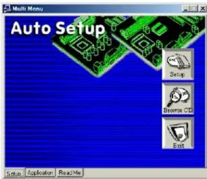

If the opening screen does not appear; double-click the file "setup.exe" in the root directory.
Setup Tab
| Setup | Click the Setup button to run the software installation program. Select from the menu which software you want to install. |
| Browse CD | The Browse CD button is the standard Windows command that allows you to open Windows Explorer and show the contents of the support CD.Before installing the software from Windows Explorer, look for a file named README.TXT, INSTALL.TXT or something similar. This file may contain important information to help you install the software correctly.Some software is installed in separate folders for different operating systems, such as DOS, WIN NT, or WIN98/95. Always go to the correct folder for the kind of OS you are using.In install the software, execute a file named SETUP.EXE or INSTALL.EXE by double-clicking the file and then following the instructions on the screen. |
| Exit | The EXIT button closes the Auto Setup window. |
Application Tab
Lists the software utilities that are available on the CD.
Read Me Tab
Displays the path for all software and drivers available on the CD.
Running Setup
Follow these instructions to install device drivers and software for the motherboard:
- Click Setup. The installation program begins:


The following screens are examples only. The screens and driver lists will be different according to the motherboard you are installing.
The motherboard identification is located in the upper left-hand corner.
*▲■★☆□※□□※□□
- Click Next. The following screen appears:

- Check the box next to the items you want to install. The default options are recommended.
- Click Next run the Installation Wizard. An item installation screen appears:
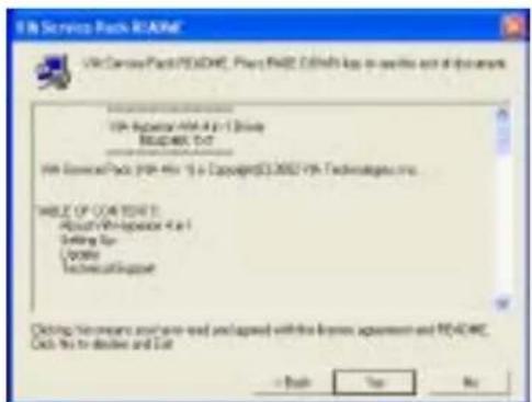
- Follow the instructions on the screen to install the items.
Drivers and software are automatically installed in sequence. Follow the onscreen instructions, confirm commands and allow the computer to restart a few times to complete the installation.
Manual Installation
Insert the CD in the CD-ROM drive and locate the PATH.DOC file in the root directory. This file contains the information needed to locate the drivers for your motherboard.
Look for the chipset and motherboard model; then browse to the directory and path to begin installing the drivers. Most drivers have a setup program (SETUP.EXE) that automatically detects your operating system before installation. Other drivers have the setup program located in the operating system subfolder.
If the driver you want to install does not have a setup program, browse to the operating system subfolder and locate the readme text file (README.TXT or README.DOC) for information on installing the driver or software for your operating system.
Utility Software Reference
All the utility software available from this page is Windows compliant. They are provided only for the convenience of the customer. The following software is furnished under license and may only be used or copied in accordance with the terms of the license.

These software(s) are subject to change at anytime without prior notice. Please refer to the support CD for available software.
AMI/AWARD Flash Memory Utility
This utility lets you erase the system BIOS stored on a Flash Memory chip on the motherboard, and lets you copy an updated version of the BIOS to the chip. Proceed with caution when using this program. If you erase the current BIOS and fail to write a new BIOS, or write a new BIOS that is incorrect, your system will malfunction. Refer to Chapter 3, Using BIOS for more information.
WinFlash Utility
The Award WinFlash utility is a Windows version of the DOS Award BIOS flash writer utility. The utility enables you to flash the system BIOS stored on a Flash Memory chip on the motherboard while in a Windows environment. This utility is currently available for WINXP\ME\2000\98SE. To install the WinFlash utility, run WINFLASH.EXE from the following directory: \UTILITY\WINFLASH 1.51
This concludes Chapter 4. Refer to the next chapter for information about SATA RAID Setup.
VIA RAID Configurations
The motherboard includes a high performance Serial ATA RAID controller integrated in the VIA VT8237 Southbridge chipset. It supports RAID 0, RAID 1 and JBOD with two independent Serial ATA channels.
RAID: (Redundant Array of Independent Disk Drives) use jointly several hard drives to increase data transfer rates and data security. It depends on the number of drives present and RAID function you select to fulfill the security or performance proposes or both.
RAID 0 (called data striping) optimizes two identical hard disk drives to read and write data in parallel, interleaved stacks. Two hard disks perform the same work as a single drive but at a sustained data transfer rate, double that of a single disk alone, thus improving data access and storage.
RAID 1 (called data mirroring) copies and maintains an identical image of data from one drive to a second drive. If one drive fails, the disk array management software directs all applications to the surviving drive as it contains a complete copy of the data in the other drive. This RAID configuration provides data protection and increases fault tolerance to the entire system.
JBOD: (Just a Bunch of Drives) Also known as “Spanning”. Two or more hard drives are required. Several hard disk types configured as a single hard disk. The hard drives are simply hooked up in series. This expands the capacity of your drive and results in a useable total capacity. However, JBOD will not increase any performance or data security.
Install the Serial ATA (SATA) hard disks
The VIA VT8237 Southbridge chipset supports Serial ATA hard disk drives. For optimal performance, install identical drives of the same model and capacity when creating a RAID set.
- If you are creating a RAID 0 (striping) array of performance, use two new drives.
- If you are creating a RAID 1 (mirroring) array for protection, you can use two new drives or use an existing drive and a new drive (the new drive must be of the same size or larger than the existing drive). If you use two drives of different sizes, the smaller capacity hard disk will be the base storage size. For example, one hard disk has an 80GB storage capacity and the other hard disk has 60GB storage capacity, the maximum storage capacity for the RAID 1 set is 60GB.
Follow these steps to install the SATA hard disks for RAID configuration.
i Before setting up your new RAID array, verify the status of your hard disks. Make sure the Master/Slave jumpers are configured properly.
ii Both the data and power SATA cables are new cables. You cannot use older 40-pin 80-conductor IDE or regular IDE power cables with Serial ATA drives. Installing Serial ATA (SATA) hard disks require the use of new Serial ATA cable (4-conductor) which supports the Serial ATA protocol and a Serial ATA power cable.
iii Either end of the Serial ATA data cable can be connected to the SATA hard disk or the SATA connector on the motherboard.
1 Install the Serial ATA hard disks into the drive bays.
2 Connect one end of the Serial ATA cable to the motherboard's primary Serial ATA connector (SATA1).
3 Connect the other end of Serial ATA cable to the master Serial ATA hard disk.
4 Connect one end of the second Serial ATA cable to the motherboard's secondary Serial ATA connector (SATA2).
5 Connect the other end of Serial ATA cable to the secondary Serial ATA hard disk.
6 Connect the Serial ATA power cable to the power connector on each drive.
7 Proceed to section "Entering VIA Tech RAID BIOS Utility" for the next procedure.
Entering VIA Tech RAID BIOS Utility
1 Boot-up your computer.
2 During POST, press

The RAID BIOS information on the setup screen shown is for reference only. What you see on your screen may not by exactly the same as shown.
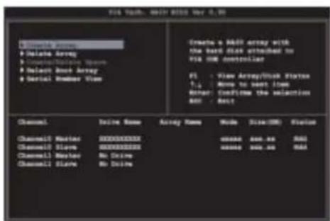
On the upper-right side of the screen is the message and legend box. The keys on the legend box allow you to navigate through the setup menu options. The message describes the function of each menu item. The following lists the keys found in the legend box with their corresponding functions.
F1 View Array
↑↓
Move to the next item
Enter Confirm the selection
ESC Exit
Create Array
1 In the VIA RAID BIOS utility main menu, select Create Array then press the
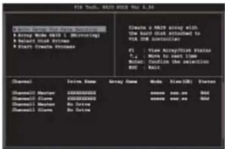
RAID 0 for performance
1 Select the second option item Array Mode, then press the

2 Select RAID 0 for performance from the menu and press
3 Select Select Disk Drives, then press
4 Select Block Size, then press

Tip For server systems, it is recommended to use a lower array block size. For multimedia computer systems used mainly for audio and video editing, a higher array block size is recommended for optimum performance.
Use arrow keys to move selection bar on items and press
5 Select Start Create Process and press
The same confirmation message appears when the Auto Setup for Performance option is selected.

Press "Y" to confirm or "N" to return to the configuration options.
RAID 1 for data protection
1 Select the second option item Array Mode, then press the

2 Select RAID 1 for data protection from the menu and press

3 Select task and press
4 Select Select Disk Drives, then press
5 Select Start Create Process and press
The same confirmation message appears when the Auto Setup for Performance option is selected.

Press "Y" to confirm or "N" to return to the configuration options.
*◇◇★◇◇√×★◇◇◇◇◇◇◇◇◇◇◇◇◇◇◇◇◇◇◇◇◇◇◇◇◇◇◇◇◇◇◇◇◇◇◇◇◇◇◇◇◇◇◇◇◇◇◇◇◇◇◇◇◇◇◇◇◇◇◇◇◇◇◇◇◇◇◇◇◇◇◇◇◇◇◇◇◇◇◇◇◇◇◇◇◇◇◇◇◇◇◇◇◇◇◇◇◇◇◇◇
Delete Array
1 In the VIA RAID BIOS utility main menu, select Delete Array then press the
2 Press the

Press "Y" to confirm or "N" to return to the configuration options.
Select Boot Array
1 In the VIA RAID BIOS utility main menu, select Select Boot Array then press the
2 Press the
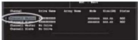
Serial Number View
1 In the VIA RAID BIOS utility main menu, select Serial Number View then press the
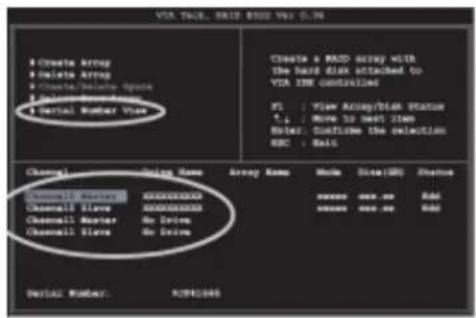
*☆☆**X•√X*☆☆☆☆☆☆☆*☆◆□◆◆◆◆
Duplicate Critical RAID 1 Array
When booting up the system, BIOS will detect if the RAID 1 array has any inconsistencies between user data and backup data. If BIOS detects any inconsistencies, the status of the disk array will be marked as critical, and BIOS will prompt the user to duplicate the RAID 1 in order to ensure the backup data consistency with the user data.

If user selects Continue to boot, it will enable duplicating the array after booting into OS.
Rebuild Broken RAID 1 Array
When booting up the system, BIOS will detect if any member disk drives of RAID has failed or is absent. If BIOS detects any disk drive failures or missing disk drives, the status of the array will be marked as broken.
If BIOS detects a broken RAID 1 array but there is a spare hard drive available for rebuilding the broken array, the spare hard drive will automatically become the mirroring drive. BIOS will show a main interface just like a duplicated RAID 1. Selecting Continue to boot enables the user to duplicate the array after booting into operating system.
If BIOS detects a broken RAID 1 array but there is no spare hard drive available for rebuilding the array, BIOS will provide several operations to solve such problems.
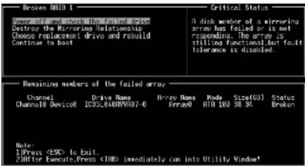
*◇◇★◇◇√×★◇◇◇◇◇◇◇◇◇◇◇◇◇◇◇◇◇◇◇◇◇◇◇◇◇◇◇◇◇◇◇◇◇◇◇◇◇◇◇◇◇◇◇◇◇◇◇◇◇◇◇◇◇◇◇◇◇◇◇◇◇◇◇◇◇◇◇◇◇◇◇◇◇◇◇◇◇◇◇◇◇◇◇◇◇◇◇◇◇◇◇◇◇◇◇◇◇◇◇◇
X
1. Power off and Check the Failed Drive:
This item turns off the computer and replaces the failed hard drive with a good one. If your computer does not support APM, you must turn off your computer manually. After replacing the hard drive, boot into BIOS and select Choose replacement drive and rebuild to rebuild the broken array.
2. Destroy the Mirroring Relationship:
This item cancels the data mirroring relationship of the broken array. For broken RAID 1 arrays, the data on the surviving disk will remain after the destroy operation. However, Destroy the Mirroring Relationship is not recommended because the data on the remaining disk will be lost when the hard drive is used to create another RAID 1 array.
3. Choose Replacement Drive and Rebuild:
This item enables users to select an already-connected hard drive to rebuild the broken array. After choosing a hard drive, the channel column will be activated.
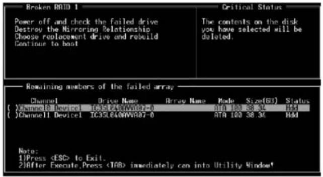
Highlight the target hard drive and press
4. Continue to boot:
This item enables BIOS to skip the problem and continue booting into OS.
Installing RAID Software & Drivers
Install Driver in Windows OS
New Windows OS (2000/XP/NT4) Installation
The following details the installation of the drivers while installing Windows XP.
1 Start the installation:
Boot from the CD-ROM. Press F6 when the message "Press F6 if you need to install third party SCSI or RAID driver" appears.
2 When the Windows Setup window is generated, press S to specify an Additional Device(s).
3 Insert the driver diskette VIA VT8237 Disk Driver into drive A: and press
4 Depending on your operation system, choose VIA Serial ATA RAID Controller (Windows XP), VIA Serial ATA RAID Controller (Windows 2000) or VIA Serial ATA RAID Controller (Windows NT4) from the list that appears on Windows XP Setup screen, press the
5 Press
6 From the Windows XP Setup screen press the
Existing Windows XP Driver Installation
1 Insert the ECS CD into the CD-ROM drive.
2 The CD will auto-run and the setup screen will appear.
3 Under the Driver tab, click on VIA SATA RAID Utility.
4 The drivers will be automatically installed.
Confirming Windows XP Driver Installation
1 From Windows XP, open the Control Panel from My Computer followed by the System icon.
2 Choose the Hardware tab, then click the Device manager tab.
3 Click the "+" in front of the SCSI and RAID Controllers hardware type. The driver VIA IDE RAID Host Controller should appear.
Installation of VIA SATA RAID Utility
The VIA SATA RAID Utility is the software package that enables high-performance RAID 0 arrays in the Windows*XP operating system. This version of VIA SATA RAID Utility contains the following key features:
- Serial ATA RAID driver for Windows XP
• VIA SATA RAID utility
• RAID0 and RAID1 functions
Insert the ECS CD and click on the Setup to install the software.

The InstallShield Wizard will begin automatically for installation. Click on the Next button to proceed the installation in the welcoming window.
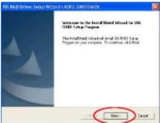
*☆☆**X•√X*☆☆☆*☆☆*☆*◆□◆◆◆◆
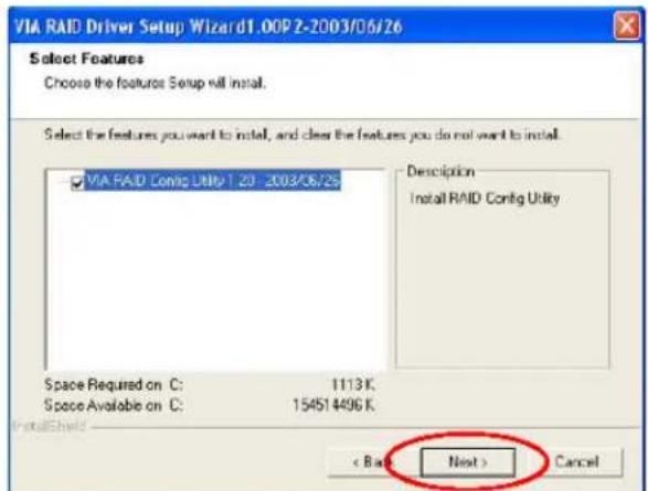
Put a check mark in the check box to install the feature you want. Then click Next button to proceed the installation.
Using VIA RAID Tool
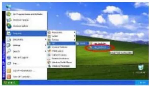
Once the installation is complete, go to Start--> Programs--> VIA--> raid_tool.exe to enable VIA RAID Tool.
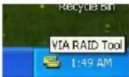
After the software is finished installation, it will automatically started every time Windows is initiated. You may double-click on the 📋 icon shown in the system tray of the tool bar to launch the VIA RAID Tool utility.
XX
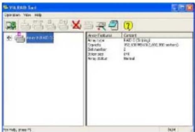
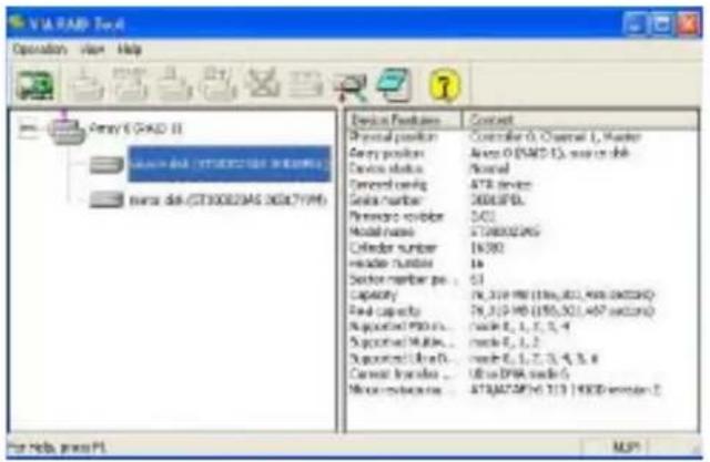
The main interface is divided into two windows and the toolbar above contain the main functions. Click on these toolbar buttons to execute their specific functions. The left windowpane displays the controller and disk drives and the right windowpane displays the details of the controller or disk drives. The available features are as following:

View by Controller

View by Devices

View Event log

Help Topics
It means that VT8237 SATA RAID only has the feature of monitoring the statuses of RAID 0 and RAID 1.
Click on or button to determine the viewing type of left windowpane. There are two viewing types: By controllers and by device. Click on the object in the left windowpane to display the status of the object in the right windowpane. The following screen shows the status of Array 0-RAID 0.
*☆☆**X•√X*☆☆☆☆☆☆☆*☆◆□◆◆◆◆
X#
Click on the plus (+) symbol next to Array 0--RAID 0 to see the details of each disk.

You may also use the same


button to view the statuses of Array 0--
RAID 1.

Click on the plus (+) symbol next to Array 0; RAID 1 to see the details of each disk.
Caractéristiques
Processeur
- ISO14001
- CERTIFICATE
- PREFACE
- USING THE MOTHERBOARD SOFTWARE 41
- VIA VT8237 SATA RAID SETUP GUIDE
- INTRODUCTION
- FEATURE
- PROCESSOR
- CHIPSET
- K8T890 (NB)
- VT8237 (SB)
- MEMORY
- AUDIO CODEC
- ONBOARD LAN (OPTIONAL)
- EXPANSION OPTIONS
- INTEGRATED I/O
- BIOS FIRMWARE
- SAFETY PRECAUTIONS
- CHOOSING A COMPUTER CASE
- INSTALLING THE MOTHERBOARD IN A CASE
- CHECKING JUMPER SETTINGS
- SETTING JUMPERS
- CONNECTING CASE COMPONENTS
- CONNECTING 20/24-PIN POWER CABLE
- FRONT PANEL HEADER
- HARD DRIVE ACTIVITY LED
- POWER/SLEEP/MESSAGE WAITING LED
- RESET SWITCH
- POWER SWITCH
- INSTALLING HARDWARE
- INSTALLING THE PROCESSOR
- BEFORE INSTALLING THE PROCESSOR
- CPU INSTALLATION PROCEDURE
- INSTALLING MEMORY MODULES
- DDR SDRAM MEMORY MODULE TABLE
- NOTES
- INSTALLATION PROCEDURE
- INSTALLING A HARD DISK DRIVE/CD-ROM/SATA HARD DRIVE
- ABOUT IDE DEVICES
- IDE1: PRIMARY IDE CONNECTOR
- IDE2: SECONDARY IDE CONNECTOR
- ABOUT ULTRADMA
- ABOUT SATA CONNECTORS
- INSTALLING SERIAL ATA HARD DRIVES
- INSTALLING A FLOPPY DISKETTE DRIVE
- FDD1: FLOPPY DISK CONNECTOR
- INSTALLING ADD-ON CARDS
- CONNECTING OPTIONAL DEVICES
- AUDIO2: FRONT PANEL AUDIO HEADER
- USB2\~3: FRONT PANEL USB HEADERS
- SATA1\~2: SERIAL ATA CONNECTORS
- SIR1: INFRARED HEADER
- CONNECTING I/O DEVICES
- ABOUT THE SETUP UTILITY
- THE STANDARD CONFIGURATION
- ENTERING THE SETUP UTILITY
- PRESS DEL/F1 TO ENTER SETUP
- BIOS NAVIGATION KEYS
- UPDATING THE BIOS
- USING BIOS
- STANDARD CMOS SETUP
- DATE AND TIME
- PRIMARY/SECONDARY/THIRD IDE MASTER/SLAVE
- TYPE (AUTO)
- LBA/LARGE MODE (AUTO)
- BLOCK (MULTI-SECTOR TRANSFER) (AUTO)
- PIO/DMA MODE (AUTO)
- S.M.A.R.T. (AUTO)
- 32BIT DATA TRANSFER (ENABLED)
- FLOPPY A/B
- ADVANCED SETUP
- QUICK BOOT (ENABLED)
- 1ST/2ND/3RD BOOT DEVICE
- TRY OTHER BOOT DEVICE (YES)
- BOOTUP NUM-LOCK (ON)
- BOOT TO OS/2 > 64MB (NO)
- DRAM CAS# LATENCY (SPD)
- AGP APERTURE SIZE (64MB)
- AUTO DETECT DIMM/PCI CLK (ENABLED)
- COOL N'QUIET (ENABLED)
- FEATURES SETUP
- ONBOARD FLOPPY CONTROLLER (ENABLED)
- SERIAL PORT1 ADDRESS (3F8/IRQ4)
- ONBOARD IR PORT (DISABLED)
- PARALLEL PORT ADDRESS (378)
- PARALLEL PORT MODE (ECP)
- ECP MODE DMA CHANNEL (DMA3)
- PARALLEL PORT IRQ (IRQ7)
- ONBOARD PCI IDE CONTROLLER (BOTH)
- ONBOARD SATA-IDE (RAID)
- AUDIO DEVICE (ENABLED)
- MODEM DEVICE (ENABLED)
- ETHERNET DEVICE (ENABLED)
- ONBOARD USB FUNCTION (ENABLED)
- USB FUNCTION FOR DOS (DISABLED)
- POWER MANGEMENT SETUP
- ACPI AWARE O/S (YES)
- POWER MANAGEMENT (ENABLED)
- SUSPEND MODE (S1)
- SUSPEND TIME OUT (DISABLED)
- RESUME ON RTC ALARM (DISABLED)
- LAN/RING POWER ON (DISABLED)
- KEYBOARD POWER ON (DISABLED)
- WAKE-UP KEY (ANY KEY)
- S3 USB DEVICE WAKEUP FUNCTION (DISABLED)
- PCI / PLUG AND PLAY SETUP
- PRIMARY GRAPHICS ADAPTER (PCI-E VGA)
- ALLOCATE IRQ TO PCI VGA (YES)
- PCI IDE BUSMASTER (DISABLED)
- BIOS SECURITY FEATURES
- SUPERVISOR PASSWORD (NOT INSTALLED)
- CHANGE SUPERVISOR PASSWORD (PRESS ENTER)
- CPU PNP SETUP
- CPU TYPE
- CPU OVER-CLOCKING FUNC. (DISABLED)
- CPU FREQUENCY
- MEMORY VOLTAGE (AUTO)
- HARDWARE MONITOR
- SYSTEM HARDWARE MONITOR
- LOAD OPTIMAL DEFAULTS
- SAVE CHANGES AND EXIT
- DISCARD CHANGES AND EXIT
- ABOUT THE SOFTWARE CD-ROM
- AUTO-INSTALLING UNDER WINDOWS 98/ME/2000/XP
- APPLICATION TAB
- READ ME TAB
- RUNNING SETUP
- MANUAL INSTALLATION
- UTILITY SOFTWARE REFERENCE
- AMI/AWARD FLASH MEMORY UTILITY
- WINFLASH UTILITY
- VIA RAID CONFIGURATIONS
- INSTALL THE SERIAL ATA (SATA) HARD DISKS
- ENTERING VIA TECH RAID BIOS UTILITY
- CREATE ARRAY
- RAID 0 FOR PERFORMANCE
- RAID 1 FOR DATA PROTECTION
- DELETE ARRAY
- SELECT BOOT ARRAY
- SERIAL NUMBER VIEW
- DUPLICATE CRITICAL RAID 1 ARRAY
- REBUILD BROKEN RAID 1 ARRAY
- POWER OFF AND CHECK THE FAILED DRIVE
- DESTROY THE MIRRORING RELATIONSHIP
- CHOOSE REPLACEMENT DRIVE AND REBUILD
- CONTINUE TO BOOT
- INSTALLING RAID SOFTWARE & DRIVERS
- NEW WINDOWS OS (2000/XP/NT4) INSTALLATION
- EXISTING WINDOWS XP DRIVER INSTALLATION
- CONFIRMING WINDOWS XP DRIVER INSTALLATION
- INSTALLATION OF VIA SATA RAID UTILITY
- USING VIA RAID TOOL
- CARACTÉRISTIQUES
- PROCESSEUR
Brand : ECS
Model : K8T890-A
Category : Motherboard