
M7-172D-PS - Tractor KUBOTA - Free user manual and instructions
Find the device manual for free M7-172D-PS KUBOTA in PDF.


| Product Type | Tractor |
| Brand | Kubota |
| Model | M7-172D-PS |
| Engine Type | Kubota V6108-CR-TIEF4, 4-cylinder, 4-cycle diesel, turbocharged, intercooled, common rail |
| Displacement | 6124 cm³ (374 cu in) |
| Rated Power | 114 kW (153 HP) at 2100 rpm |
| Maximum Torque | 704 N·m at 1500 rpm |
| PTO Power | 104.4 kW (140 HP) at 2000 rpm |
| Transmission | Power shift, 6-speed main, 5-speed range, with optional creep |
| Travel Speeds (forward) | 0.37 to 40 km/h (0.23 to 24.9 mph) with creep; up to 50 km/h (31.1 mph) in high range |
| Steering | Hydrostatic power steering with telescopic column |
| Brakes | Hydraulically operated wet disc, with optional hydraulic or pneumatic trailer brake |
| Overall Dimensions (L x W x H) | 4770 x 2500 x 3010 mm (187.8 x 98.4 x 118.5 in) |
| Wheelbase | 2720 mm (107.1 in) |
| Weight (approx.) | 6980 kg (15390 lbs) |
| Fuel Tank Capacity | 330 L (87.2 US gal) |
| DEF/AdBlue Capacity | 38 L (10 US qts) |
| Hydraulic System | Open center, pump capacity 80 L/min (21.1 US gpm), system pressure 20.0 MPa (208 kgf/cm²) |
| 3-Point Hitch | Category 3/3N, maximum lifting force 9400 kg (20720 lbs) at lift points |
| PTO | Independent, 4 speeds: 540/540E/1000/1000E rpm, clockwise rotation |
| Front PTO (optional) | 1000 rpm, 21 splines, 1 3/8 in shaft |
| Safety Features | CAB/ROPS, seat belt, operator presence control, safety labels, SMV emblem, and more |
| Maintenance Intervals | Engine oil change every 500 hours, transmission fluid change every 1000 hours, refer to manual for full schedule |
Frequently Asked Questions - M7-172D-PS KUBOTA
User questions about M7-172D-PS KUBOTA
0 question about this device. Answer the ones you know or ask your own.
Ask a new question about this device
Download the instructions for your Tractor in PDF format for free! Find your manual M7-172D-PS - KUBOTA and take your electronic device back in hand. On this page are published all the documents necessary for the use of your device. M7-172D-PS by KUBOTA.
USER MANUAL M7-172D-PS KUBOTA
5900 14th Avenue, Markham, Ontario, L3S 4K4, Canada
France : KUBOTA EUROPE S.A.S
19-25, Rue Jules Vercruysse, Z.I. BP38, 95101 Argenteuil Cedex, France
Italy : KUBOTA EUROPE S.A.S Italy Branch
Via Grandi, 20 20068 Peschiora Borrome (MI) Italy
Telephone (39)02-51650377
Germany : KUBOTA (DEUTSCHLAND) GmbH
Senefelder Str. 3-5 62110 Rodgau /Nieder-Roden, Germany
U.K.: KUBOTA (U.K.) LTD.
Corner Road, Thame, Oxfordshire, CX9 3UN, U.K.
Telephone: (44)1844-2:4500
Spain : KUBOTA ESPAÑA S.A.
Avenida Recomba No.5, Poligno Industrial la Laguna, Legenes, 28914 (Madrid) Spain
Australia : KUBOTA AUSTRALIA PTY LTD.
26-29 Fennas Way, Truganina, VIC 3029. Australia
Malaysia : KUBOTA MALAYSIA SDN. BHD.
No.3 Jalan Sepadu 25/123 Taman Perindustrian Axis.
Sekayan 25, 40400 Shah Alam. Seengor Darul Ensan Malaysia
Telephone: (00)3-756-1388
Philippines: KUBOTA PHILIPPINES, INC.
232 Gurino Highway, Baesa, Quezon City 1106, Philippines
Taiwan : SHIN TAIWAN AGRICULTURAL MACHINERY CO., LTD.
- Fengping 2nd Rd, Taiyao Shiang Kaohsiung 83107, Taiwan R.O.C.
Telephone (886)7-702-2333
Indonesia : PT KUBOTA MACHINERY INDONESIA
Tower A at EightyEight@Kasablanka Lantel 16
Jalan Raya Casablanka Kav. 88, Jakarta 12870 Indonesia
Thailand : SIAM KUBOTA CORPORATION CO., LTD.
101/19-24 Moo 20, Novanskom Industrial Estate, Tambon Khilongrueng, Amphur Khilongluang.
Pathumihani 12120, THAILAND
Telephone 16602-909-0300
Korea : KUBOTA KOREA CO., LTD.
41-27, Jayumuyook-gil, Boekson-myson, Gimje-si, Jeollabuk-do, Korea
Telephone (82)-63-544-5822
India : KUBOTA AGRICULTURAL MACHINERY INDIA PVT. LTD.
No.15, Medavakkam Road, Shalingansllur, Chennai-600119, T.N., India
Telephone : (01)44-5104-1500
Vietnam : KUBOTA VIETNAM CO., LTD.
Lot B-3A2-CN, My Phuoc 2 Industrial Park, Thol Hoa Ward, Ben Cai Town, Birh Duong Province, Vietnam
Telephone (84)274-3577-507
KUBOTA Corporation
English (U.S.A.)
Code No. 3J036-5919-2
AX.J.4-4.-AK
© KUBOTA Corporation 2018
OPERATOR'S MANUAL
KUBOTA TRACTOR
M7-132·M7-152·M7-172MODELS

natural_image
Line drawing of a modern trill tractor with large tires and front wheel (no text or symbols)READ AND SAVE THIS MANUAL
Kubota
ABBREVIATION LIST
| Abbreviations | Definitions Abbreviations Definitions |
| 2WD | 2 Wheel Drive |
| 4WD | 4 Wheel Drive |
| API | American Petroleum Institute |
| ASABE | American Society of Agricultural and Biological Engineers, USA |
| ASTM | American Society for Testing and Materials, USA |
| CVT | Continuously Variable Transmission |
| DEF | Diesel Exhaust Fluid |
| DT | Dual Traction [4WD] |
| fpm | Feel Per Minute |
| DPF | Diesel Particulate Filter |
| GST | Glide Shift Transmission |
| Hi-Lo | High Speed-Low Speed |
| HST | Hydrostatic Transmission |
| m/s | Meters Per Second |
| PTO | Power Take Off |
| RH/LH | Right-hand and left-hand sides are determined by facing in the direction of forward travel |
| ROPS | Roll-Over Protective Structures |
| rpm | Revolutions Per Minute |
| r/s | Revolutions Per Second |
| SAE | Society of Automotive Engineers, USA |
| SCR | Selective Catalytic Reduction |
| SMV | Slow Moving Vehicle |
California Proposition 65
WARNING
Engine exhaust, some of its constituents.
certain vehicle components and fluids,
contain or emit chemicals known to the
State of California to cause cancer and birth
defects or other reproductive harm
Canadian Electromagnetic Compatibility (EMC): This machine complies with Industry Canada ICES-002.
KUBOTA Corporation is …
Since its Inception in 1890, KUBOTA Corporation has grown to rank as one of the major firms in Japan.
To achieve this status, the company has through the years diversified the range of its products and services to a remarkable extent. 30 plants and 35000 employees produce over 1000 different items, large and small.
All these products and all the services which accompany them, however, are unified by one central commitment. KUBOTA makes products which, taken on a national scale, are basic necessities. Products which are indispensable. Products which are intended to help individuals and nations fulfill the potential inherent in their environment. KUBOTA is the Basic Necessities Giant.
This potential includes water supply, food from the soil and from the sea, industrial development, architecture and construction, and transportation.
Thousands of people depend on KUBOTA's know-how, technology, experience and customer service. You too can depend on KUBOTA.
UNIVERSAL SYMBOLS
As a guide to the operation of your tractor, various universal symbols have been utilized on the instruments and controls. The symbols are shown below with an indication of their meaning.

General


Safety alert symbol
Master system warning
Fast
Slow
Creep
Read operator's manual
Lock
On (engaged)
Off (disengaged)
Service

Engine-related


n/min
Diesel fuel
Hour meter / elapsed operating hours
Engine coolant - temperature
Low temperature regulation
Engine intake/combustion air-filter
Engine oil - pressure
Water separator
Engine - warning
Engine - rotational speed


Engine - rev limiter
Engine - rev limiter
Engine - over-speed
Engine - rpm memory A
Engine - rpm adjuster
Engine - rpm increase
Engine - run
Engine - start
Engine - stop
Electrical power - accessories
Diesel preheat / glow plugs (low temperature start aid)
Emission control
Regeneration
Regeneration inhibit
Regeneration (switch)
Parked regeneration
DEF/AdBlue® - level

DEF/AdBlue ® - low level
DEF/AdBlue ® - poor quality
DEF/AdBlue ® - trouble
DEF/AdBlue ® - thawing
■ Vehicle body-related

Travel direction - forward
Travel direction - rearward
Travel direction
4-wheel drive - on
4-wheel drive - on
4-wheel drive - automatic
Headland management system
Cruise control
Limp home
Escape
Operator presence control
Auto-transmission
Auto-transmission - sensitivity
Auto-transmission - road control
Auto-transmission - field control

Transmission oil filter
Low temperature regulation
Gear shifting warning
Clutch
Brake
Parking brake
Parking brake / brake oil
Air brake
Trailer brake warning
Differential lock
Differential lock - automatic
Steering wheel - tilt
Steering wheel - telescope
Automatic steering control
Steering oil filter
Front suspension
Front suspension - automatic
Front suspension - down
Front suspension - up
Front suspension - lock
PTO-related

PTO - off (disengaged)

PTO - on (engaged)

540

540E

1000

1000E

PTO - 540 rpm
PTO - 540E rpm
PTO - 1000 rpm
PTO - 1000E rpm
PTO - front

PTO - front

PTO - rear

PTO - rear
Hydraulic-related

Draft control
Position control

Hydraulic oil filter

Lift arm control - up / transport

Lift arm control - up

Lift arm control - down

Lift arm control - down

Lift arm control - block

Lift arm control - float

Lift arm control - lock

3-point lifting / lowering

Lift arm - height

Remote cylinder - retract

Remote cylinder - extend

Remote cylinder - float

Remote cylinder - lock

Remote cylinder - lock
Electric-related

Battery charging condition

Master lighting switch

Headlight - low beam

Headlight - high beam

Headlight - flashing

Work light

Position lamps

Turn signal

Turn signal - trailer

Hazard warning lights

Audible warning device

Beacon light

Windshield wiper

Windshield wiper - intermittent

Windshield washer

Rear window defroster
FOREWORD
You are now the proud owner of a Kubota tractor. This tractor is a product of Kubota quality engineering and manufacturing. It is made of fine materials and under a rigid quality control system. It will give you long, satisfactory service. To obtain the best use of your tractor, please read this manual carefully. It will help you become familiar with the operation of the tractor and contains many helpful hints about tractor maintenance. It is Kubota's policy to utilize as quickly as possible every advance in our research. The immediate use of new techniques in the manufacture of products may cause some small parts of this manual to be outdated. Kubota distributors and dealers will have the most up-to-date information. Please do not hesitate to consult with them.

SAFETY FIRST
This symbol, the industry's safety alert symbol, is used throughout this manual and on labels on the machine itself to warn of the possibility of personal injury. Read these instructions carefully. It is essential that you read the instructions and safety regulations before you attempt to assemble or use this unit.

DANGER: Indicates an imminently hazardous situation which, if not avoided, will result in death or serious injury.

WARNING: Indicates a potentially hazardous situation which, if not avoided, could result in death or serious injury.

CAUTION: Indicates a potentially hazardous situation which, if not avoided, could result in minor or moderate injury.
IMPORTANT: Indicates that equipment or property damage could result if instructions are not followed.
NOTE: Gives helpful information.
CONTENTS
SAFE OPERATION....11
SERVICING OF TRACTOR 27
WARRANTY 28
SCRAPPING THE TRACTOR AND ITS PROCEDURE 28
SPECIFICATIONS....29
SPECIFICATION TABLE....29
TRAVELING SPEEDS 31
IMPLEMENT LIMITATIONS....33
TRAILER LOAD CAPACITY 34
FRONT LOADER....35
INSTRUMENT PANEL AND CONTROLS....37
SWITCHES AND HAND CONTROLS 37
INSTRUMENT PANEL 38
FOOT AND HAND CONTROLS 39
INTELLIPANEL™ CONTROL 46
INSTRUMENT PANEL 46
LIQUID CRYSTAL DISPLAY (LCD) 47
- LCD initial setting....49
1.1 Setting the clock....49
1.2 Setting the clock display ON/OFF 50
1.3 Setting the working range of implement....50
- Setting the power shift transmission (Standard, Deluxe model) 50
2.1 Setting the automatic gear shift (road mode)....50
2.2 Setting the automatic gear shift (field mode)....51
- Basic information monitor and performance monitor....53
3.1 Modifying the information displayed on the basic information monitor....57
3.2 Modifying the information to display on the performance monitor....57
3.3 Measuring distance 58
INDICATORS 60
- Indicator color....61
K-MONITOR MAIN MENU (PREMIUM AND PREMIUM KVT MODELS ONLY) 61
-
Names of parts and their handling (K-monitor)....62
-
Names of parts and their handling (K-monitor Pro) 64
-
Basic procedures....66
3.1 Changing the screen settings....67
3.2 [F] buttons....68
3.3 Function of the "Home" button 68
3.4 Function of the [ESC] button....68
- System basic settings....69
4.1 Calling up the setting screen (K-monitor)....69
4.2 Calling up the setting screen (K-monitor Pro) 69
4.3 Setting items and adjusting the setting mode screen....69
4.3.1 System settings (1) screen 69
4.3.2 System settings (2) screen 70
4.3.3 Time and date settings screen....70
4.3.4 ISOBUS settings screen 70
4.3.5 License confirmation screen 71
-
Setting the 3-point hitch....72
-
Setting the remote control valve 74
6.1 Detailed settings of remote control valve 76
-
Setting the drivability ....77
-
Setting the PTO 79
-
Setting the engine and power shift transmission (Premium model only)....80
9.1 Setting the traveling speed gear in the road mode 81
9.2 Setting the traveling speed gear in the field mode 81
9.3 Setting the auto shift sensitivity 83
9.4 Setting the engine rev-limit....84
9.5 Setting the engine rpm memory 84
- Setting the engine and CVT (Premium KVT model only) 85
10.1 Modifying the CVT sensitivity setting 86
10.2 Modifying the CVT response setting 86
10.3 Modifying the CVT low-range maximum speed setting....87
10.4 Cruise control speed setting....87
10.5 Setting the engine rev-limit....87
10.6 Setting the engine rpm memory 87
- Setting the headland management system....88
11.1 Preparations for recording the program....88
11.2 Recording the program through actual tractor operation....89
11.3 Pre-program lead time and pre-program travel distance....89
11.4 Saving the program 90
11.5 Loading the program 91
11.6 Deleting the program....92
11.7 Modifying the program (lead time)....92
11.8 Modifying the program (switching)....93
11.9 Headland management system program list....95
- Operating conditions....100
12.1 Calling up the data screen and preparation 100
12.2 Selecting and registering recorded data items.... 101
12.3 Recordable data items 101
12.4 Setting the operating conditions and beginning recording 102
12.5 Record status indicators.... 102
K-MONITOR SUB-MENU (PREMIUM AND PREMIUM KVT MODELS ONLY) 102
-
Live view camera....103
-
Calculator 103
-
Initial setting....103
-
Data import and export 103
4.1 Exporting procedure....103
4.2 Importing procedure 104
-
Screenshot 104
-
Failure messages 105
PRE-OPERATION CHECK....106
DAILY CHECK 106
SERVICE INSPECT INDICATOR 106
-
Checking the items reaching the maintenance interval 106
-
Resetting the maintenance hour....108
- Dual exhaust aftertreatment devices 109
DIESEL PARTICULATE FILTER (DPF) MUFFLER 109
-
Handling points....109
-
DPF regeneration process.... 110
-
Operating procedure for auto regeneration mode 111
3.1 PM warning level and required procedures.... 112
- Operating procedure for regeneration inhibit mode 113
4.1 PM warning level and required procedures.... 114
-
Operating procedure for parked regeneration 115
-
Tips on diesel particulate filter (DPF) regeneration 116
SELECTIVE CATALYTIC REDUCTION (SCR) MUFFLER.... 116
-
Outline of the SCR.... 116
-
DEF/AdBlue ® 116
-
Warning indication and countermeasures 117
3.1 SCR system inducement display on the LCD 117
3.2 SCR system icon on inducement display 117
3.3 SCR system inducement display and measures.... 118
- Storing and handling DEF/AdBlue 121
STARTING THE ENGINE 121
-
Setting the battery switch 121
-
Engine starting procedure 121
STARTING THE ENGINE IN COLD WEATHER....122
-
Antifrost heater for oil separator (if equipped) 122
-
Block heater (if equipped).... 122
-
Engine low temperature regulation....122
-
DEF/AdBlue ® freeze warning 123
STOPPING THE ENGINE....123
WARMING UP THE ENGINE 123
-
Warm-up and transmission fluid at low temperature range 123
-
Transmission low temperature (premium KVT model only) 124
JUMP STARTING 124
-
Key switch 125
-
Engine power boost....125
-
Rev-limiter control setting 125
-
RPM dual memory setting 126
4.1 Setting the speeds (Standard and Deluxe models).... 128
4.2 Setting the speeds (Premium and Premium KVT models) 128
4.3 Canceling the setting (all models)....129
-
Do not operate the tractor at full speed for the first 50 hours 130
-
Changing lubricating oil for new tractors 130
BOARDING AND LEAVING THE TRACTOR 130
-
Operator's seat 130
-
Operator presence control (OPC) system 132
-
Seat belt 132
-
Instructional seat (if equipped) 133
4.1 Precautions in using the instructional seat.... 133
-
Steering adjustment.... 134
-
Extendable mirror 134
-
2-sided mirror (if equipped) 134
-
Heater for rear view mirror (if equipped)....134
-
Remote control mirror (if equipped) 135
LIGHT CONTROLS....135
- Lights 135
1.1 Light switch (without repeat headlight type) 135
1.2 Light switch (with repeat headlight type).... 136
- Turn signal switch and hazard light switch 137
2.1 Horn button 137
-
Work light switch....137
-
Beacon light switch....138
BRAKE CONTROLS 138
- Foot brake 138
1.1 4WD braking system (4WD model)....139
- Parking brake 139
2.1 When towing a dual-line trailer brake type trailer 140
- Trailer brake....140
3.1 Confirmation....140
3.2 Hydraulic trailer brake 140
3.3 Pneumatic trailer brake 140
3.3.1 Inspecting the pneumatic pressure 141
3.4 Trailer brake warning indicator 141
TRAVEL CONTROLS 141
-
Clutch pedal.... 141
-
Hand throttle 142
-
Foot throttle 142
-
Shuttle lever....142
5.Shuttle button 143
6.Shuttle neutral button 143
-
Creep speed (if equipped) 144
-
4WD and AUTO 4WD switch....145
8.1 Selection of 4WD modes.... 145
8.2 Switching of 4WD modes 145
8.3 4WD indicator....146
8.4 Front-wheel drive usage....146
- Differential lock 146
9.1 Selection of differential lock modes.... 146
9.2 Switching of differential lock modes 146
9.3 Differential lock indicator 147
POWER SHIFT TRANSMISSION CONTROL 148
-
Switching the operation modes 148
-
Switching the auto shift modes 149
-
Traveling speeds 150
3.1 Setting the traveling speed gear in the road mode (Standard, Deluxe model).... 150
3.2 Setting the main gear shift range in the field mode (Standard, Deluxe model) 150
3.3 Setting the range gear shift in the field mode (Standard, Deluxe model) 151
3.4 Setting the traveling speed range in the road mode (Premium model).... 151
3.5 Setting the main gear shift range in the field mode (Premium model) 152
3.6 Setting the range gear shift in the field mode (Premium model) 153
- Operating in the manual mode 153
4.1 Operating the main gear shift 153
4.2 Operating the range gear shift 154
-
Example of operation on combined auto-shift-and-manual mode 154
-
Setting the auto shift sensitivity 154
-
Limp home switch....155
CONTINUOUSLY VARIABLE TRANSMISSION (CVT) CONTROL.... 156
- Traveling operation 156
1.1 Main shift.... 157
1.2 Mode shift.... 157
1.3 Modifying the maximum traveling speed.... 157
-
Operation of the automatic mode 158
-
Operation of the manual engine speed setting mode 159
-
Setting the continuously variable transmission (CVT) sensitivity 160
-
Setting the continuously variable transmission (CVT) response 161
-
Cruise control 161
6.1 Setting the cruise control.... 161
6.2 Clearing the cruise control 162
-
Ratio lock button....162
-
Limp home switch....162
STOPPING THE TRACTOR 163
CHECK DURING DRIVING 163
-
Engine over-speed limiting indicator.... 163
-
Gear shifting warning indicator (Standard, Deluxe, Premium models only).... 163
- Easy Checker ™ 164
- Fuel gauge....166
- DEF/AdBlue ® gauge....166
- Pneumatic pressure gauge (if equipped).... 166
- Coolant temperature gauge....166
- Tachometer 167
HEADLAND MANAGEMENT SYSTEM 167
- Programming the headland management system.... 168
- Loading a program to the program code 168
- Handling the headland management system 168
FRONT SUSPENSION (IF EQUIPPED) 170
- Front suspension modes 171
- Switching of the modes 171
- How to read the suspension indicator 172
- Traveling speed and modes 172
PARKING THE TRACTOR....172
- Trailer operation.... 172
OPERATING TECHNIQUES....173
- Operating the tractor on a road 173
- Operating on slopes and rough terrain 173
- Transporting the tractor safely 173
- Directions for the use of power steering 174
PTO 175
-
External switch for rear PTO....176
-
PTO operating mode selector lever and PTO gear shift lever 176
- 1000 rpm PTO shaft 177
- PTO shaft cover and shaft cap 178
- Auto PTO operation (Premium and Premium KVT models) 179
FRONT PTO OPERATION (IF EQUIPPED) 180
- PTO clutch control switch 180
1.1 PTO clutch indicator 180
1.2 PTO rpm display....180 - PTO shaft cover and shaft cap 181
3-POINT HITCH AND DRAWBAR....182
THE 3-POINT HITCH SETUP....183
- Adjusting lateral float 183
- Selecting the top link mounting holes 183
- Drawbar 184
- Remote hitch "UP" switch and "DOWN" switch 184
- Lifting rod 184
- Top link 185
- Stabilizer 185
- Sway limitation plate 185
- Telescopic lower links 186
DRAWBAR 186
- Adjusting drawbar length 186
- Swing drawbar 186
FRONT 3-POINT HITCH (IF EQUIPPED) 186
- Lift control 187
- Remote hitch "UP" switch and "DOWN" switch (if equipped) 187
-
Switching of the hydraulic valve 188
-
Lower link 188
- Top link 189
HYDRAULIC UNIT....190
3-POINT HITCH CONTROL SYSTEM....190
- Terminology (Standard, Deluxe models).... 190
- Terminology (Premium and Premium KVT models) 191
- 3-point hitch lock button....192
- Position and mix draft mode select.... 192
- Depth control adjustment dial (hydraulic dial).... 193
- Position control 193
- Mix draft control 194
- Float control....194
- Lift arm top limit adjustment.... 194
- 3-point hitch lowering speed adjustment ..... 195
- 3-point quick raise and lower switches 196
- 3-point hitch's position lock.... 197
- Ride control 197
AUXILIARY HYDRAULICS 197
- Power-beyond type hydraulic outlet for Deluxe, Premium and Premium KVT models (if equipped).... 198
- Hydraulic drain port 198
REMOTE HYDRAULIC CONTROL SYSTEM....198
- Operation of Standard and Deluxe models.... 198
1.1 Controls of remote valves 198
1.2 Remote control valve 199
1.3 Flow control valve 199
1.4 Remote control valve lever 200
- Operation of Premium and Premium KVT models 201
2.1 Controls of remote valves 201
2.2 Remote control valve lock button 202
2.3 Detailed setting of remote control valve 202
2.4 Remote control valve switch 203
2.5 Joystick for remote control valve and loader (loader model)....203
2.6 Controls for the remote control valves on the rear fender (if equipped).... 204
- Common operation for all models....204
3.1 Connecting cylinder and hydraulic motor 204
3.2 Remote control valve coupler 205
3.3 Remote couplers spillage collector 206
- Hydraulic control unit use reference chart....207
TIRES, WHEELS AND BALLAST....209
TIRES....209
- Inflation pressure 209
- Jack point 210
- Safe replacement of the wheel 211
WHEEL ADJUSTMENT 211
- Adjusting front wheels with 4-wheel drive....212
- Adjusting the front wheel turning stopper bolt 213
- Adjusting rear wheels with flange type axle....214
- Adjusting wheels with bar type axle 215
- Bar type axle....216
- Flange type axle 217
BALLAST 217
- Front ballast....217
1.1 Front end weights (option) 217 - Rear ballast for single tires 217
2.1 Rear wheel weights (option)....217
2.2 Liquid ballast in rear tires 218
2.3 Monolithic block (if equipped) 218
2.4 Maximum masses 218
CAB OPERATION....219
CAB CLASSIFICATION AND MAINTENANCE....219
DOORS AND WINDOWS 219
- Locking and unlocking the door....219
- Opening the door....219
- Rear window 220
- Sun roof 220
- Emergency exit....220
DOME LIGHT 220
SPOT LIGHT (IF EQUIPPED)....221
WIPER 221
- Front wiper and washer switch 221
- Rear wiper and washer switch....221
- Using the wipers in cold season....221
AIR CONDITIONER....222
- Airflow 222
- Air control vent....222
2.1 Dashboard air outlet 222
2.2 Rear air outlet....222
- Control panel 223
3.1 Mode switch 223
3.2 Temperature control dial....223
3.3 Blower switch 223
3.4 Air conditioner switch 223
3.5 Recirculation or fresh air selection switch 223
- Operation....223
4.1 Heating....223
4.2 Cooling or dehumidifying-heating....224
4.3 Defrosting or demisting 225
REAR DEFOGGER WITH TIMER (IF EQUIPPED) 225
ACCESSORIES 226
- Trailer electrical outlet....226
2.ISOBUS socket (Premium and Premium KVT models only)....227 - Electrical outlet socket....227
4.ISOBUS monitor socket (Premium and Premium KVT models only)....228 - Signal socket according to ISO standard 11786 (Premium and Premium KVT models only)....228
- Cigarette lighter 228
INSTALLING THE IMPLEMENT CONTROL BOX 229
BEACON LIGHT 229
MAINTENANCE....230
SERVICE INTERVALS....230
MAINTENANCE ITEMS CHART....231
LUBRICANTS, FUEL AND COOLANT 233
- Biodiesel fuel (BDF) B0-B20....235
PERIODIC SERVICE 237
WASTE DISPOSAL 237
HOW TO OPEN THE HOOD 237
- Hood 237
- Side cover....237
DAILY CHECK 238
- Walk around inspection 238
- Checking and refueling....238
-
Checking antifrost heater for oil separator (if equipped)....238
-
Checking DEF/AdBlue ® level and adding fluid 239
-
Checking pneumatic brake pressure (if equipped) 240
-
Checking water separator 240
-
Checking engine oil level....241
-
Checking transmission fluid level 241
-
Checking coolant level....242
-
Cleaning grill, radiator, and cooler 242
-
Checking DPF/SCR muffler 243
-
Checking brake pedal 244
-
Checking parking brake 244
-
Checking gauges, meter and Easy Checker™ 244
-
Checking headlight, turn signal light, hazard light, and so on 244
-
Checking seat belt 244
-
Checking movable parts 244
INITIAL 5, 10, 25, AND 50 HOURS ...... 244
- Tightening bar axle torque 245
INITIAL 50 HOURS 245
-
Changing engine oil 245
-
Replacing engine oil filter 245
-
Checking fan belt....245
-
Replacing transmission oil filter 245
EVERY 50 HOURS....245
- Checking neutral circuit 245
1.1 Preparation before testing 245
1.2 Testing engine start system....245
1.3 Testing transmission (neutral) control 246
1.4 Testing hydraulic up/down (lock) control 246
1.5 Testing remote hydraulic control (Premium and Premium KVT models) 246
1.6 Testing external rear PTO switch control....247
1.7 Testing operator presence control (OPC) system of PTO 247
1.8 Testing operator presence control (OPC) system of shuttle lever (Standard, Premium models)...248
1.9 Testing operator presence control (OPC) system of shuttle lever (Premium KVT model) 249
-
Checking wheel bolt torque 249
-
Checking tie-rod dust cover 249
-
Checking air brake for trailer (if equipped) 250
EVERY 100 HOURS....250
- Cleaning air cleaner primary element 250
1.1 Cleaning pre-cleaner tubes 250
1.2 Replacing secondary element....251
-
Lubricating grease fittings....251
-
Adjusting brake pedal 252
3.1 Checking brake pedal free travel 252
3.2 Checking brake pedal stroke....253
3.3 Checking equalizer working level (anti-imbalance device)....253
-
Adjusting parking brake lever 253
-
Checking battery condition 253
5.1 Charging the battery 254
5.2 Directions for battery storage 254
5.3 How to detach the battery 254
- Checking front PTO oil (if equipped)....255
EVERY 200 HOURS....255
-
Draining fuel tank water 255
-
Adjusting toe-in 256
2.1 Adjusting toe-in procedure 256
-
Cleaning inner air filter 256
-
Cleaning fresh air filter 256
4.1 Cleaning the filter 257
EVERY 250 HOURS....257
- Cleaning pre-fuel filter 257
- Replacing fuel filter 258
- Checking fuel line 258
EVERY 400 HOURS....259
- Checking fan belt tension 259
1.1 Replacing the belt 259
2. Cleaning water separator 260
3. Cleaning fuel solenoid pump element 261
INITIAL 500 HOURS....261
- Changing transmission fluid ....261
- Changing rear axle case oil 261
- Replacing transmission oil filter 261
EVERY 500 HOURS....262
- Changing engine oil....262
- Replacing engine oil filter 262
- Replacing hydraulic oil filter (suction) 262
- Replacing hydraulic oil filter (return) 264
- Replacing power steering oil filter....264
- Checking radiator hose and clamp 265
6.1 Overheating countermeasures....266
- Checking intake air line 266
- Checking brake hose....266
- Checking differential lock hose....266
- Checking lift cylinder hose....267
- Checking power steering line....267
- Checking oil cooler line....267
- Checking front suspension hose 267
- Checking air conditioner pipe and hose 268
- Checking air conditioner drive belt 268
15.1 Replacing the belt 268
- Changing front PTO oil (if equipped) 269
EVERY 1000 HOURS....269
- Changing transmission fluid 269
- Replacing transmission oil filter 270
- Changing rear axle case oil 271
- Changing front differential case oil 272
- Changing front axle gear case oil 272
- Adjusting engine valve clearance 273
EVERY 1000 HOURS OR 1 YEAR....273
- Replacing air cleaner primary element and secondary element....273
- Checking exhaust manifold 273
EVERY 1500 HOURS....273
- Cleaning fuel injector nozzle tip....273
- Checking DEF/AdBlue® injector tip 273
- Checking DEF/AdBlue ® line 273
- Replacing oil separator element 273
- Checking positive crankcase ventilation (PCV) valve 273
- Checking and cleaning EGR cooler....274
- Checking accumulator (front suspension type) 274
EVERY 2000 HOURS OR 2 YEARS 274
- Flushing cooling system and changing coolant 274
- Antifreeze 275
EVERY 3000 HOURS....275
- Checking turbocharger 275
- Checking supply pump 275
- Checking and cleaning EGR system 275
- Checking DEF/AdBlue® injector 275
- Replacing DEF/AdBlue® pump filter 276
EVERY 4000 HOURS....276
- Cleaning DPF muffler 276
EVERY 1 YEAR....276
- Checking DPF differential pressure sensor pipe 276
- Checking EGR pipe 276
- Checking oil separator hose 276
- Checking antifrost heater for oil separator (if equipped) 276
- Checking CAB isolation cushion....276
EVERY 2 YEARS....276
- Replacing DPF differential pressure sensor hose 276
- Replacing boost sensor hose 276
- Replacing fuel hose 276
EVERY 3 YEARS....277
- Replacing parking brake cable 277
EVERY 4 YEARS....277
- Replacing radiator hose (water pipes) 277
- Replacing intake air line 277
- Replacing oil separator hose 277
- Replacing oil cooler line....277
- Replacing power steering line 277
- Replacing lift cylinder hose 277
- Replacing suspension hose (front suspension type) 277
- Replacing differential lock hose 277
- Replacing brake hose 277
- Replacing air conditioner hose 277
SERVICE AS REQUIRED....277
- Bleeding fuel system 277
- Bleeding brake system 278
- Replacing fuses 279
- Replacing light bulb 282
- Replacing head lamp 282
- Lubricating points for door and window 282
- Adding washer liquid 282
- Checking amount of refrigerant (gas) 282
- Washing the tractor 283
STORAGE......285
TRACTOR STORAGE 285
REMOVING THE TRACTOR FROM STORAGE 285
TROUBLESHOOTING....286
ELECTRIC CONTROLLER TROUBLE SHOOTING....286
OPTIONS 293
OPTIONS 293
APPENDICES 294
MAXIMUM MASSES....294
- Maximum permissible load of the tire 294
INDEX......295
SAFE OPERATION
Careful operation is your best insurance against an accident.
Read and understand this manual carefully before operating the tractor.
All operators, no matter how much experience they may have, should read this and other related manuals before operating the tractor or any implement attached to it. It is the owner's obligation to instruct all operators in safe operation.
Know your equipment and its limitations. Read this entire manual before attempting to start and operate the tractor.
1. General
- Pay special attention to the safety labels on the tractor.
- Do not operate the tractor or any implement attached to it while under the influence of alcohol, medication, controlled substances or while fatigued.
- Before allowing other people to use your tractor, explain how to operate and have them read this manual before operation.
- Never wear loose, torn, or bulky clothing around the tractor. It may catch on moving parts or controls, leading to the risk of an accident.
Use additional safety items, such as a hard hat, safety boots or shoes, eye and hearing protection, gloves and so on, as appropriate or required.
- Do not allow passengers to ride on any part of the tractor at any time. The operator must remain in the tractor seat during operation.
- Check brakes, clutch, linkage pins and other mechanical parts for improper adjustment and wear. Replace worn or damaged parts promptly. Check the tightness of all nuts and bolts regularly. (See MAINTENANCE on page 230.)
- Keep your tractor clean. Dirt, grease, and trash buildup may contribute to fires and lead to personal injury.
- Use only implements meeting the specifications listed in this manual or implements approved by Kubota. (See IMPLEMENT LIMITATIONS on page 33.)
- Use proper weights on the front or rear of the tractor to reduce the risk of upsets. When using the front loader, put an implement or ballast on the 3-point hitch to maintain proper balance and braking.
Follow the safe operating procedures specified in the implement or attachment manual.
- The narrower the tread, the greater the risk of a tractor upset. For maximum stability, adjust the wheels to the widest practical tread width for your application.
(See TIRES, WHEELS AND BALLAST on page 209.)
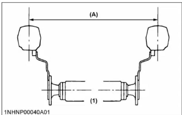
(1) Rear wheels
(A) Tread width
- Do not modify the tractor. Unauthorized modification may affect the function of the tractor, which may result in personal injury.
2. CAB and ROPS
- Kubota recommends the use of a CAB or roll-over protective structures (ROPS) and seat belt in almost all applications. This combination will reduce the risk of serious injury or death, should the tractor be upset. Check for overhead clearance which may interfere with a CAB or ROPS.
- If the CAB or ROPS is loosened or removed for any reason, make sure that all parts are reinstalled correctly before operating the tractor.
- Never modify or repair any structural member of a CAB or ROPS because welding, bending, drilling, grinding, or cutting may weaken the structure.
- If any structural member of the CAB or ROPS is damaged, replace the entire structure at your local KUBOTA Dealer.
- Always use the seat belt if the tractor has a CAB or ROPS. Do not use the seat belt if there is no ROPS. Check the seat belt regularly and replace if frayed or damaged.
- The CAB is not tested for FOPS (falling object protection structure).
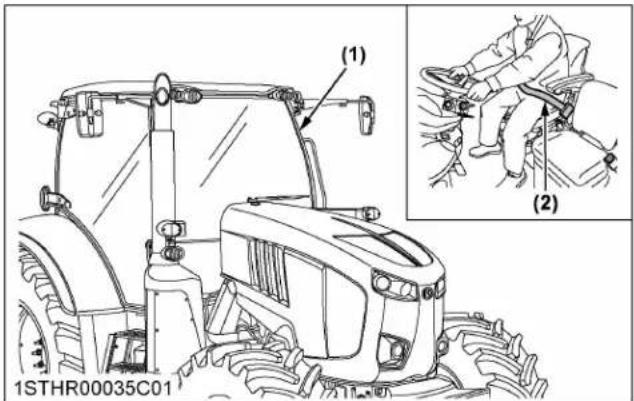
(1) CAB
(2) Seat belt
- Front loader must be used with the sun roof closed.
• The CAB fulfills the requirements of category type 2.
- The air delivery and filtration system of the category 2 CAB protects against airborne and sedimented solid particles.
• The CAB provides protection against dust but not against aerosols and vapors.
- The CAB cannot be used under conditions repairing protection against aerosols and vapors.
Operator safety is a priority. Safe operation, specifically with respect to overturning hazards, entails understanding the equipment and environmental conditions at the time of use.
Some prohibited uses which can affect overturning hazards include traveling and turning with implements, loads carried too high and so on. This manual sets forth some of the obvious risks, but the list is not, and cannot be, exhaustive. It is the operator's responsibility to be alert for any equipment or environmental condition that could compromise safe operation.
1. Starting to operate the tractor
- Always sit in the operator's seat when starting engine or operating levers or controls. Adjust seat per instructions in the operating the tractor section. Never start engine while standing on the ground.
- Before starting the engine, make sure that all levers (including auxiliary control levers) are in their neutral positions and that the parking brake is engaged. Fasten the seat belt if the tractor has a CAB, a fixed ROPS or a foldable ROPS in the upright and locked position.
- Do not start engine by shorting across starter terminals or bypassing the safety start switch. The machine may start in gear and move if the normal starting circuitry is bypassed.
- Do not operate or idle the engine in a non-ventilated area. Carbon monoxide gas is colorless, odorless, and deadly.
- Check before each use that the operator presence controls (OPC) are functioning correctly. Test the safety systems.
(See Checking neutral circuit on page 245.)
Do not operate unless they are functioning correctly.
2. Working the tractor
- Pull only from the drawbar. Never hitch to axle housing or any other point except the drawbar; such arrangements will increase the risk of serious personal injury or death due to a tractor upset.

(1) Drawbar
- For trailing PTO-driven implements, set the drawbar to the towing position.
- Attach pulled or towed loads to the drawbar only.
- Keep all shields and guards in place. Replace any that are missing or damaged.
- Avoid sudden starts. To avoid upsets, slow down when turning, on uneven ground, and before stopping.
• The tractor cannot turn with the differential locked and attempting to do so could be dangerous.
- Do not operate near ditches, holes, embankments, or other ground surface features which may collapse under the tractor's weight. The risk of tractor upset is even higher when the ground is loose or wet. Tall grass can hide obstacles; walk the area first to be sure.
- Watch where you are going at all times. Watch for and avoid obstacles. Be alert at row ends, near trees, and other obstructions.
- When working in groups, always let the others know what you are going to do before you do it.
- Never try to get on or off a moving tractor.
• Always sit in the operator's seat when operating levers or controls.
- Do not stand between tractor and implement or trailed vehicle unless the parking brake is applied.
- Never utilize the headland management system, if anyone is in the work area of the tractor.
- Do not operate the tractor when there is a possibility of lightning. Even if the tractor is equipped with a CAB, the operator is not protected from lightning.
- Whenever the tractor is operated in reverse, confirm visibility to the rear.
3. Instructional seat (if equipped)
• Always wear your seat belt and stabilize your body by holding the handrail on the CAB frame.
- It is not intended to carry children nor any other person for any other purpose.
- The left-hand door must be closed at all time whenever the instructional seat is occupied and the tractor is in motion.
- Do not permit others to ride, except on the designated instructional seat.
- Use caution to avoid the risks of obstructing operator's view, falling from the machine and interfering with controls.
- Do not start and stop the tractor suddenly, nor take a sharp turn.
- Do not use the instructional seat if the seat belt or the door lock fails to function.
- Do not use the instructional seat for transport.
- When opening or closing the door while being seated in the instructional seat, move the door slowly. This is to prevent his or her hand(s) from getting caught by the door or his or her body to hit against the door.
4. Safety for children
Tragedy can occur if the operator is not alert to the presence of children. Children generally are attracted to machines and the work they do.
- Never assume that children will remain where you last saw them.
- Keep children out of the work area and under the watchful eye of another responsible adult.
- Be alert and shut your machine down if children enter the work area.
- Never carry children on your machine. There is no safe place for them to ride. They may fall off and be run over or interfere with your control of the machine.
- Never allow children to operate the machine even under adult supervision.
- Never allow children to play on the machine or on the implement.
- Use extra caution when backing up. Look behind and down to make sure area is clear before moving.
5. Operating on slopes
Slopes are a major factor related to loss-of-control and tip-over accidents, which can result in severe injury or death. All slopes require extra caution.
- To avoid upsets, always back up steep slopes. If you cannot back up the slope or if you feel uneasy on it, do not operate on it. Stay off slopes too steep for safe operation.
- Driving forward out of a ditch, mired condition or up a steep slope increases the risk of rear rollovers. Always back out of these situations. Extra caution is required with 4-wheel drive models because their increased traction can give the operator false confidence in the tractor's ability to climb slopes.
- Keep all movement on slopes slow and gradual. Do not make sudden changes in speed, direction or braking, nor make sudden motions with the steering wheel.
- Avoid disengaging the clutch or changing gears when climbing or going down a slope. If on a slope, disengaging the clutch or changing gears to neutral could cause the loss of control.
- Special attention should be paid to the weight and location of implements and loads as such will affect the stability of the tractor.
- To improve stability on slopes, set the widest possible wheel tread. (See TIRES, WHEELS AND BALLAST on page 209.) Follow the recommendations for proper ballasting.
• To avoid free wheeling:
- Do not shift the shuttle lever while on a slope.
- Stop completely by using the brakes and by depressing the clutch pedal, then shift the shuttle lever.
- Start off after selecting shuttle direction, by releasing the clutch pedal.
- When driving down a slope, ensure that 4-wheel drive is engaged to increase traction and braking efficacy (if equipped).
6. Driving the tractor on the road
- Lock the 2 brake pedals together to help assure straight-line stops. Uneven braking at road speeds could cause the tractor to tip over.
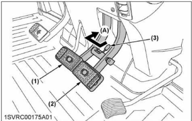
(1) Brake pedal (LH)
(2) Brake pedal (RH)
(3) Brake pedal lock
(A) Whenever traveling on the road
- Check the front wheel engagement. The braking characteristics are different between 2 and 4-wheel drive. Be aware of the difference and use carefully.
- When driving down a slope, ensure that the 4-wheel drive is engaged to increase traction and braking efficacy (if equipped).
• Always slow the tractor down before turning. Turning at high speed may tip the tractor over. - Make sure that the slow moving vehicle (SMV) sign is clean and visible. Use hazard lights and turn signals as required.

(1) SMV emblem
(2) Bracket
- Observe all local traffic and safety regulations.
- Turn the headlights on. Dim them when meeting another vehicle.
- Drive at speeds that allow you to maintain control at all times.
- Do not apply the differential lock while traveling at road speeds. The tractor may run out of control.
- Avoid sudden motions of the steering wheel as they can lead to a dangerous loss of stability. The risk is especially great when the tractor is traveling at road speeds.
- Do not operate an implement while the tractor is on the road. Lock the 3-point hitch in the raised position. For travelling with the ride control on, however, keep the 3-point hitch unlocked.
- When towing other equipment, use a safety chain and place an SMV emblem on it as well.
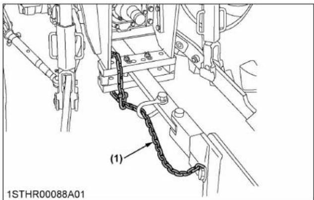
(1) Safety chain
- Set the 3-point hitch lock button in the "LOCK" position to hold the implement in the raised position.
Standard, Deluxe model
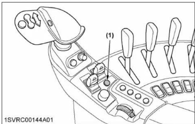
(1) 3-point hitch lock button
Premium, Premium KVT model

(1) 3-point hitch lock button
- If you drive the tractor with a trailer loaded with something heavy in tow and step on the brake pedal, the tractor is pushed forward by the trailer due to an abrupt slowdown. This may fail to keep the tractor under control.
Before stepping on the brake pedal, press the transmission ratio lock button for smooth slowdown in combination with the engine brake (Premium KVT model).
PARKING THE TRACTOR
- Disengage the PTO, lower all implements to the ground, place all control levers in their neutral positions, set the parking brake, stop the engine, remove the key from the ignition and lock the CAB door (if equipped).
Leaving transmission in gear with the engine stopped will not prevent tractor from rolling.
- Make sure that the tractor has come to a complete stop before dismounting.
- Avoid parking on steep slopes. If at all possible, park on a firm and level surface; if not, park across a slope and chock the wheels.
Failure to comply with this warning may allow the tractor to move and could cause injury or death.
OPERATING THE PTO
- Wait until all moving components have completely stopped before getting off the tractor, connecting, disconnecting, adjusting, cleaning, or servicing any PTO driven equipment.
- Keep the PTO shaft cover in place at all times. Put back the PTO shaft cap when the shaft is not in use.

(1) PTO shaft cover
(2) PTO shaft cap
(A) "NORMAL POSITION"
(B) "RAISED POSITION"
- Before installing or using PTO driven equipment, read the manufacturer's manual and review the safety labels attached to the equipment.
To prevent PTO driven equipment from improper or unsafe use, select the lower speed (540 rpm) unless the higher one is specifically recommended as safe by the equipment manufacturer. - When operating stationary PTO driven equipment, always apply the tractor parking brake and place chocks behind and in front of the rear wheels. Stay
clear of all rotating parts. Never step over rotating parts.
USING 3-POINT HITCH
- Use the 3-point hitch only with equipment designed for the appropriate category of 3-point hitch usage.
- When using a 3-point hitch mounted implement, be sure to install the proper counterbalance weight on the front of the tractor.
- To avoid injuries like pinching fingers while raising or lowering the 3-point hitch: Keep away from moving parts like lift arms, lifting rods, or lower links.
- To avoid injury from separation: Do not extend the lift rod beyond the groove on the threaded rod.

(1) Groove
- Use the "UP" switch and "DOWN" switch or dial only on farm fields. For all other applications, use the depth control dial (hydraulic dial) to move the attachment.
TOWING A TRAILER
- Connect the trailer after carefully confirming its brake type and the tractor connector. Connection errors will inhibit full brake performance, which is extremely dangerous.
(See Trailer brake on page 140.)
| Brake type of trailer | Tractor |
| Dual line trailer brake (Pneumatic) | Connect to dual line connector |
| Single line trailer brake (Hydraulic) | Connect to single line connector |
SERVICING THE TRACTOR
Before servicing the tractor, park it on a firm, flat and level surface, set the parking brake, lower all

SAFE OPERATION
implements to the ground, place the shuttle lever in neutral, stop the engine and remove the key.
- Allow the tractor time to cool off before working on or near the engine, muffler, radiator and so on.
- Do not remove radiator cap while coolant is hot. When cool, slowly rotate cap to the first stop and allow sufficient time for excess pressure to escape before removing the cap completely. If the tractor has a coolant recovery tank, add coolant or water to the recovery tank, not the radiator. (See Checking coolant level on page 242.)
- Always stop the engine before refueling. Avoid spills and overfilling.
- Do not smoke when working around battery or when refueling. Keep all sparks and flames away from battery and fuel tank. The battery presents an explosive hazard, because it gives off hydrogen and oxygen especially when recharging.
- Before "jump starting" a dead battery, read and follow all of the instructions. (See JUMP STARTING on page 124.)
- Keep first aid kit and fire extinguisher handy at all times.
- Disconnect the battery's ground cable before working on or near electric components.
- To avoid the possibility of battery explosion, do not use or charge the refillable type battery if the fluid level is below the [LOWER] (lower limit level) mark. Check the fluid level regularly and add distilled water as required so that the fluid level is between the [UPPER] and [LOWER] levels.
- To avoid sparks from an accidental short circuit, always disconnect the battery's ground cable (-) first and reconnect it last.

(1) Battery
- Do not attempt to mount a tire on a rim. This should be done by a qualified person with the proper equipment.
- Always maintain the correct tire pressure. Do not inflate tires above the recommended pressure shown in the operator's manual.

natural_image
Illustration of a person falling into a circular mechanical component with radiating lines, symbolizing impact or damage (no text or symbols present)- Securely support the tractor when either changing wheels or adjusting the wheel tread width.
- Make sure that wheel bolts have been tightened to the specified torque.
- Disconnect the battery's ground cable and stop the engine to avoid the possibility of the machine runaway due to 4WD braking system during testing, service or repair with only rear wheels off the ground.
- Do not work under any hydraulically supported devices. They can settle, suddenly leak down, or be accidentally lowered. If it is necessary to work under tractor or any machine elements for servicing or adjustment, securely support them with stands or suitable blocking beforehand.
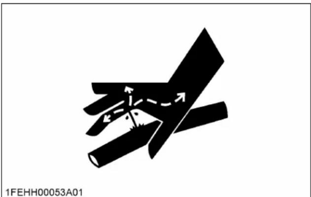
- Escaping hydraulic fluid under pressure has sufficient force to penetrate skin, causing serious personal injury. Before disconnecting hydraulic lines, be sure to release all residual pressure. Before applying pressure to the hydraulic system, make sure that all connections are tight and that all lines, pipes, and hoses are free of damage.
natural_image
Abstract black-and-white diagram of intersecting diagonal and horizontal lines with directional arrows, no readable text or symbols- Fluid escaping from pinholes may be invisible. Do not use hands to search for suspected leaks; use a piece of cardboard or wood. Use of safety goggles or other eye protection is also highly recommended. If injured by escaping fluid, see a medical doctor at once. This fluid will produce gangrene or severe allergic reactions.

(1) Cardboard
(2) Hydraulic line
(3) Magnifying glass
- Do not open the high-pressure fuel system.
High-pressure fluid remaining in fuel lines can cause serious injury. Do not disconnect or attempt to repair fuel lines, sensors, or any other components between the high-pressure fuel pump and injectors on engines with high pressure common rail fuel system.
- To avoid hazardous high voltage, turn the key switch to the "OFF" position if it is necessary to check or repair the computer, harness or connectors.
- During diesel particulate filter (hereinafter called DPF) regenerating operations, exhaust gases and exhaust filter components reach temperatures hot enough to burn people, or ignite or melt common materials.
- Keep the tractor away from people, animals or structures which may be susceptible to harm or damage from hot exhaust gases.
- To prevent fires, keep the DPF/SCR muffler and its surroundings clear of anything flammable and keep clean at all times (selective catalytic reduction - hereinafter called SCR).
• To avoid fire hazard:
After use and pressure-washing, make sure there is nothing flammable near the exhaust pipe. Grass or twigs under the bonnet may cause fire.
- During regeneration, white exhaust gas may be visible. Do not allow regeneration in a non-ventilated space.
- During regeneration, do not leave the tractor.
-
The improper disposal or burning of waste causes environmental pollution and can be punishable by your local laws and regulations.
-
When draining fluids from the tractor, place a container underneath the drain port.
- Do not pour waste onto the ground, down a drain, or into any water source (such as rivers, streams, lakes, marshes, seas and oceans).
- Waste products such as used oil, fuel, coolant, hydraulic fluid, urea aqueous solution (DEF/AdBlue®), refrigerant, solvent, filters, rubber,
batteries and harmful substances, can harm the environment, people, pets and wildlife.
Please dispose properly.
See your local recycling center or KUBOTA Dealer to learn how to recycle or get rid of waste products.
- Before servicing a tractor equipped with the front suspension, be sure to lower the machine to the lowest position.
- The front suspension hydraulic circuit is still under high pressure after the engine has stopped. Do not disconnect the pipes and/or hoses because you may get injured by high-pressure oil. If pipes and/or hoses are found worn or damaged, consult your local KUBOTA Dealer for this service.
SAFETY LABELS
(1) Part No. 3Y205-9835-1
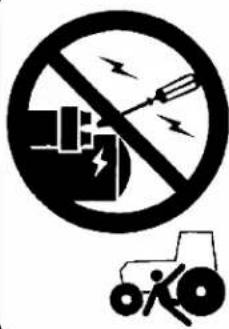

DANGER
TO AVOID POSSIBLE INJURY OR DEATH FROM A MACHINE RUNAWAY.
- Do not start engine by shorting across starter terminals or bypassing the safety start switch. Machine may start in gear and move if normal starting circuitry is bypassed.
- Start engine only from operator's seat with transmission and PTO OFF. Never start engine while standing on the ground.
(2) Part No. TC420-4956-1
Diesel fuel only.
No fire.
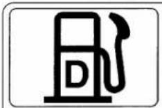

ULTRA LOW SULFUR DIESEL FUEL ONLY
(3) Part No. TC750-4958-1
Do not touch hot surfaces.


1STHR00146A01enUS
(1) Part No. TA040-4957-1 Do not open the safety shields while the engine is running.

(2) Part No. 3N300-4958-1 Do not touch hot surfaces.

(3) Part No. 3N600-4958-1 Do not touch hot surface like supply pump, and so on.

(4) Part No. 3S205-9868-1

(5) Part No. 3F240-9819-1 Do not stand by IMPLEMENT or between implement and tractor while operating remote hitch switch.

(6) Part No. 3J080-3822-1




1STHR00147A01enUS
(1) Part No. 3S205-9836-1
WARNING
TO AVOID PERSONAL INJURY OR DEATH:
-
Read and understand the operator's manual before operation.
-
Before starting the engine, make sure that everyone is at a safe distance from tractor and the PTO is off.
-
Do not allow passengers on the tractor at any time.
-
Before allowing other people to use the tractor, have them read the operator's manual.
-
Check the tightness of nuts and bolts regularly.
-
Keep all shields in place and stay away from all moving parts.
-
Lock the two brake pedals together before driving on the road.
-
Slow down for turns, or rough roads, or when applying individual brakes.
-
On public roads use SMV emblem and hazard lights, if required by local traffic and safety regulations.
10.Pull only from the drawbar.
-
Before dismounting, lower the implement to the ground, set the parking brake, stop the engine and remove the key.
-
Securely support tractor and implements before working underneath.
(2) Part No. 3Y205-9831-1

WARNING
TO AVOID FREE WHEELING WHEN SHIFTING THE SHUTTLE LEVER WHILE ON A SLOPE:
Stop completely by using the brake and by depressing the clutch pedal.
Start off after selecting shuttle direction by releasing the clutch pedal.

WARNING
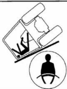
natural_image
Illustration of a person lying down with a circular icon showing a seated figure (no text or symbols)TO AVOID INJURY OR DEATH FROM ROLL-OVER:
Always use seat belt when driving.
(3) Part No. 3Y205-9832-2

WARNING

BEFORE DISMOUNTING TRACTOR:
Leaving transmission in gear with the engine stopped will not prevent tractor from rolling.
2. PARK ON LEVEL GROUND WHENEVER POSSIBLE.
If parking on a slope, position tractor across the slope.
3. LOWER ALL IMPLEMENTS TO THE GROUND.
Failure to comply to this warning may allow the wheels to slip, and could cause injury or death.
4. STOP THE ENGINE.

(4) Part No. 3S205-9778-2
If optional instructional seat is installed

WARNING
TO AVOID PERSONAL INJURY OR DEATH WHEN USING THE INSTRUCTIONAL SEAT:
- Always wear your seat belt and stabilize your body by holding the handrail on the CAB frame.
• The instructional seat is not intended to carry children nor any other person for any other purposes.
• The left hand door must be closed at all time whenever the instructional seat is occupied and the tractor is in motion.
- Do not permit others to ride, except on the designated instructional seat.
- Use caution to avoid the risks of obstructing operator's view, falling from the machine and interfering with controls.
- Do not start and stop the tractor suddenly, nor take sharp turn.
- Do not use the instructional seat if the seat belt or the door lock fails to function.
- Do not use the instructional seat for transport.
- When opening and closing the door from the instructional-seat-sitting position, move the door slowly. This is to prevent his or her hand (s) from getting caught by the door or his or her body to hit against the door.
1STHR00148A01enUS
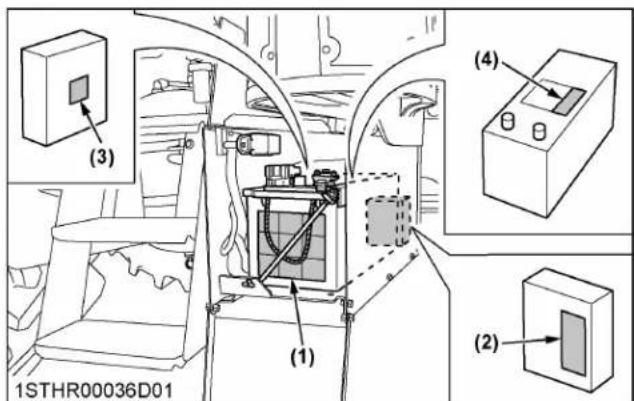
(1) Part No. 3J032-6021-1
Shield Eyes, Explosive Gases can cause blindness or injury.
No Sparks, No Flames, No Smoking. Sulfuric acid can cause blindness or severe burns.
Hazardous high Voltage. Keep away from Children. Do not tip. Do not open battery.
Flush Eyes immediately with water.
Get medical help fast.
Wash hands after handling.
(2) Part No. 3P903-9883-1
Hazardous high voltage.
Turn the starter switch to the "OFF" position if it is necessary to check or repair the computer, harness, or connectors.
(3) Part No. 1J524-8721-1
Hazardous high voltage.
Turn the starter switch to the "OFF" position if it is necessary to check or repair the computer, harness, or connectors.

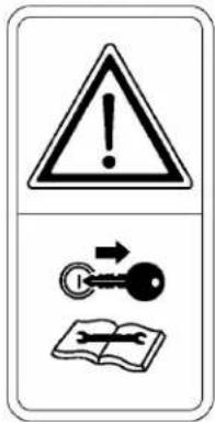

(4) Part No. 3J080-3835-1
CALIFORNIA PROPOSITION 65 ⚠️ WARNING:
Batteries, battery posts, terminals and related accessories contain lead and lead compounds, and other chemicals known to the State of California to cause cancer and birth defects or other reproductive harm.

1STHR00149A01enUS

(1) Part No. 6C200-4959-1

WARNING
TO AVOID PERSONAL INJURY:
- Attach pulled or towed loads to the drawbar only.
- Use the 3-point hitch only with equipment designed for 3-point hitch usage.


WARNING
TO AVOID PERSONAL INJURY:
- Keep PTO shield in place at all times.
- Do not operate the PTO at speeds faster than the speed recommended by the implement manufacturer.
- For trailing PTO-driven implements, set drawbar at towing position. (see operator's manual)
(2) Part No. TC430-4959-1


WARNING
TO AVOID PERSONAL INJURY.
- Keep PTO shield in place at all times.
- Do not operate the PTO at speeds faster than the speed recommended by the implement manufacturer
- For trailing PTO-driven implements, set drawbar at towing position. (see operator's manual)
(3) Part No. 3J080-1298-1
WARNING
TO AVOID INJURY OR DEATH FROM SEPARATION:
DO NOT EXTEND LIFT ROD
BEYOND THE GROOVE
ON THE THREADED ROD.
GROOVE



1STHR00150A01enUS
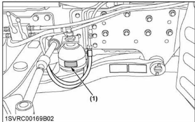
(1) Part No. 3J080-3859-1

WARNING
TO AVOID PERSONAL INJURY OR DEATH :
Servicing of high pressure oil/air device should be performed only by authorized Kubota dealer.

Front suspension type
Front suspension type

Front suspension type

1STHR00151A01enUS
(1) Part No. 3J080-1309-1
WARNING
USE [UP-DOWN] ONLY ON FARM FIELDS. FOR ALL OTHER APPLICATIONS, USE HYDRAULIC DIAL TO MOVE ATTACHMENT.
natural_image
Technical line drawing of a mechanical device with labeled component (1), no readable text or symbols present.
Maximum road speed

(2) Part No. 6C430-4754-1
California Proposition 65
WARNING
Engine exhaust, some of its constituents, certain vehicle components and fluids, contain or emit chemicals known to the State of California to cause cancer and birth defects or other reproductive harm.
(3) Part No. 3B791-9870-1
WARNING
TO AVOID EXPOSURE TO DUST CONTAINING SILICA PARTICLES:
• This dust can cause serious injury to the lungs under some exposure levels.
- Be aware of and follow the OSHA (or other regulatory body) guidelines for exposure to airborne crystalline silica.
• To meet OSHA silica guidelines, use appropriate Personal Protective Equipment and dust abatement systems, such as waterspray systems.
(4) Part No. 3S565-9855-2
Front suspension type
WARNING
TO AVOID PERSONAL INJURY OR DEATH.
Before operating the switches for the front suspension, make sure the area near the machine is clear of all persons and objects.
(5) Part No. 3F240-9821-1
WARNING
TO AVOID MACHINE RUNAWAY DUE TO 4WD BRAKING SYSTEM:
Do not run engine with only rear wheels off ground.
1STHR00152A01enUS
CARE OF THE SAFETY LABELS
- Keep the safety labels clean and free from obstructing material.
- Clean the safety labels with soap and water, dry with a soft cloth.
- Replace damaged or missing safety labels with new labels from your local KUBOTA Dealer.
- If a component with safety label(s) affixed is replaced with new part, make sure new label(s) is (are) attached in the same location(s) as the replaced component.
- Mount new safety labels by applying on a clean dry surface and pressing any bubbles to outside edge.
SERVICING OF TRACTOR
Your dealer has knowledge of your new tractor and has the desire to help you get the most value from it.
After reading this manual thoroughly, you will find that you can do some of the regular maintenance yourself. However, when in need of parts or major service, be sure to see your KUBOTA Dealer.
For service, contact the KUBOTA Dealership from which you purchased your tractor or your local KUBOTA Dealer.
When in need of parts, be prepared to give your dealer the tractor, CAB/ROPS and engine serial numbers.
Locate the serial numbers now and record them in the space provided.
| Date of purchase | |
| Name of dealer |
To be filled in by purchaser
| Type Serial No. | ||
| Tractor | ||
| CAB/ROPS | ||
| Engine | ||
To be filled in by purchaser

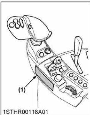
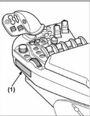
(1) Tractor identification plate
(2) Tractor serial number (last 5 digits)
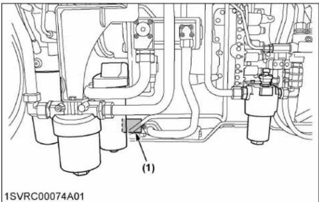
(1) Transmission identification plate

(1) Engine serial number

(1) CAB identification plate (CAB serial number)

(1) Diesel particulate filter (DPF) serial number (2) Selective catalytic reduction (SCR) muffler serial number

(1) Front axle identification plate
WARRANTY
This tractor is warranted under the KUBOAT Limited Express Warranty, a copy of which may be obtained from your selling dealer.
No warranty shall, however, apply if the tractor has not been handled according to the instruction given in the operator's manual, even if it is within the warranty period.
SCRAPPING THE TRACTOR AND ITS PROCEDURE
To put the tractor out of service, correctly follow the local rules and regulations of the country or territory where you scrap it.
If you have questions, consult your local KUBOTA Dealer.
SPECIFICATIONS
SPECIFICATION TABLE
| Model | Standard Deluxe Premium Premium KVT | |||||||||||
| M7-152 | M7-172 | M7-152 | M7-172 | M7-132 | M7-152 | M7-172 | M7-132 | M7-152 | M7-172 | |||
| Engine | Model Kubota V6108-CR-TIEF4 | |||||||||||
| Type Direct injection, water-cooled | 4 cycle diesel, common rail system, turbocharger, intercooler | |||||||||||
| Number of cylinders 4 | ||||||||||||
| Total displacement | cm3 (cu.in.) | 6124 (374) | ||||||||||
| Bore and stroke mm (in.) | 118 x 140 | (4.65 x 5.51) | ||||||||||
| Rated power*1 | kW (HP) /rpm | 99.3(133) /2100 | 114.0(153) /2100 | 99.3(133) /2100 | 114.0(153) /2100 | 84.6(113) /2100 | 99.3(133) /2100 | 114.0(153) /2100 | 84.6(113) /2100 | 99.3(133) /2100 | 114.0(153) /2100 | |
| Maximum torque (with-out boost) | N·m /rpm | 682 /1500 | 704 /1500 | 682 /1500 | 704 /1500 | 594 /1500 | 682 /1500 | 704 /1500 | 594 /1500 | 682 /1500 | 704 /1500 | |
| PTO power*2 | kW (HP) /rpm | 89.5(120) /2000 | 104.4(140) /2000 | 89.5(120) /2000 | 104.4(140) /2000 | 74.6(100) /2000 | 89.5(120) /2000 | 104.4(140) /2000 | 74.6(100) /2000 | 89.5(120) /2000 | 104.4(140) /2000 | |
| Additional boost power | kW (HP) | +14.7(+20) | +3.7(+5) | +14.7(+20) | +3.7(+5) | +14.7(+20) | +3.7(+5) | +14.7(+20) | +3.7(+5) | |||
| Maximum power with boost | rpm | 1900 | ||||||||||
| HP | 168 | 173 | 168 | 173 | 148 | 168 | 173 | 148 | 168 | 173 | ||
| Battery capacity | 174 Ah (20 HR) / 1400 A | |||||||||||
| Fuel tank capacity | L(U.S.gals.) | 330 (87.2) | ||||||||||
| Engine oil capacity | L(U.S.qts.) | 22 (5.8) | ||||||||||
| Coolant capacity | L(U.S.qts.) | 24 (6.3) | ||||||||||
| DEF/AdBlue®capacity | L(U.S.qts.) | 38 (10) | ||||||||||
| Dimensions | Overall length | mm (in.) | 4770 (187.8) with ballast carrier / 4790 (188.6) with front linkage | |||||||||
| Overall width (mini-mum tread) | mm (in.) | 2500 (98.4) with flange axle /2825 (111.2) with bar axle | ||||||||||
| Overall height | mm (in.) | 3010 (118.5) | ||||||||||
| Wheel base | mm (in.) | 2720 (107.1) | ||||||||||
| Tread | Front | mm (in.) | 1537 to 2237 (60.5 to 88.1) | |||||||||
| Rear | mm (in.) | 1582 to 2086 (62.3 to 82.1) | ||||||||||
| Crop clearance | mm (in.) | 370 to 410 (14.6 to 16.1) | ||||||||||
| Weight | kg (lbs.) | 6730 (14840) | 6980 (15390) | |||||||||
| Travelingsystem | Standard tire size | Front tires | 540/65R28, 420/85R28, 380/85R30, 380/85R28, 320/85R34 | |||||||||
| Rear tires | 650/65R38, 480/80R42, 460/85R42, 460/85R38, 420/80R46, 380/90R46 | |||||||||||
| Transmis-sion | Type | Power shift | CVT | |||||||||
| Main gear shift | 6-speed power shift | |||||||||||
(Continued)
| Model | Standard Deluxe Premium Premium KVT | |||||||||||
| M7-152 | M7-172 | M7-152 | M7-172 | M7-132 | M7-152 | M7-172 | M7-132 | M7-152 | ||||
| Traveling system | Transmission | Range gear shift | 5-speed synchronized (GST) | CVT | ||||||||
| No. of speeds F30/R15 | (F54/R27 with optional creep) | |||||||||||
| Clutch Multiple wet disc, electronic-hydraulic operated | ||||||||||||
| Steering | Hydrostatic power steering Hydrostatic, with telescopic steering column for steering wheel height adjustment | |||||||||||
| 4-wheel drive change Electronic hydraulically operated | ||||||||||||
| Braking system Hydraulically operated wet disk | ||||||||||||
| Trailer brake | Hydraulic (standard) Pneumatic (option) | |||||||||||
| Differential lock Front and rear | Electronic hydraulically operated (actuated front and rear at the same time) | |||||||||||
| Hydraulic unit | Hydraulic control system | Open center sys-tem | Closed center with load sensing | |||||||||
| Pump capacity*3(For rear lift and re-mote hydraulic) | L(U.S.gals.) / min | 80 (21.1) 110 | (29.1) | |||||||||
| 3-point hitch Category 3/3N | ||||||||||||
| Hydraulic lifting cylinder diameter | mm (in.) | 100 (3.9) | ||||||||||
| Max. lifting force | At lifting points | kg (lbs.) | 9400 (20720) | |||||||||
| 24 inches behind lift-ing point*4 | kg (lbs.) | 5350 (11790) | ||||||||||
| Remote hydraulic control | Mechanical valve, max. 4 valves | Electronic control valve, max. 5 valves | ||||||||||
| System pressure | MPa (kgf/cm2) | 20.0 (208) | ||||||||||
| Traction system | Quick hook type lower link | |||||||||||
| Front lift (option) | Max. lifting capacity at link end | kg (lbs.) | 3900 (8598) | |||||||||
| Max. lifting capacity in full stroke | kg (lbs.) | 3200 (7055) | ||||||||||
| PTO | Live PTO (independent) | Clutch | Electric controlled, multiple wet disc with independent brake | |||||||||
| Direction of turning | Clockwise, viewed from tractor rear | |||||||||||
| PTO/ engine speed | rpm | 4 speed with 6 and 21 splines: 540/2005, 540E/1608, 1000/1995, 1000E/1600 | ||||||||||
| Front PTO (option) | Shaft diameter 1" 3/8 | |||||||||||
| PTO shaft splines | 21 | |||||||||||
| 1000 PTO engine rpm | 1930 | |||||||||||
The company reserves the right to change the specifications without notice.
*1 According to 97/68EC
*2 Manufacturer's estimate
*3 Theoretical value
*4 Top link mounting: upper hole
TRAVELING SPEEDS
Standard, Deluxe, Premium models
| 40 km/h (24.9 mph) model 50 km/h (31.1 mph) model | ||||||||||
| Tire size (rear) 650/65R38 | ||||||||||
| Creep lever (option) | Range gear shift | Main gear shift | Forward Reverse | Forward Reverse | ||||||
| km/h mph | km/h mph | km/h mph | km/h mph | |||||||
| ON | A | 1 0.37 | 0.23 0.40 0.25 | 0.37 0.23 0.40 | 0.25 | |||||
| 2 0.44 | 0.27 0.56 0.35 | 0.44 0.27 0.56 | 0.35 | |||||||
| 3 0.51 | 0.32 0.78 0.48 | 0.51 0.32 0.78 | 0.48 | |||||||
| 4 0.60 | 0.37 — — | 0.60 0.37 — | — | |||||||
| 5 0.72 | 0.45 — — | 0.72 0.45 — | — | |||||||
| 6 0.84 | 0.52 — — | 0.84 0.52 — | — | |||||||
| B | 1 0.66 | 0.41 0.72 0.45 | 0.66 0.41 0.72 | 0.45 | ||||||
| 2 0.78 | 0.48 1.00 0.62 | 0.78 0.48 1.00 | 0.62 | |||||||
| 3 0.92 | 0.57 1.40 0.87 | 0.92 0.57 1.40 | 0.87 | |||||||
| 4 1.08 | 0.67 — — | 1.08 0.67 — | — | |||||||
| 5 1.28 | 0.80 — — | 1.28 0.80 — | — | |||||||
| 6 1.51 | 0.94 — — | 1.51 0.94 — | — | |||||||
| C | 1 1.00 | 0.62 1.09 0.68 | 1.00 0.62 1.09 | 0.68 | ||||||
| 2 1.17 | 0.73 1.51 0.94 | 1.17 0.73 1.51 | 0.94 | |||||||
| 3 1.38 | 0.86 2.11 1.31 | 1.38 0.86 2.11 | 1.31 | |||||||
| 4 1.63 | 1.01 — — | 1.63 1.01 — | — | |||||||
| 5 1.93 | 1.20 — — | 1.93 1.20 — | — | |||||||
| 6 2.27 | 1.41 — — | 2.27 1.41 — | — | |||||||
| D | 1 1.68 | 1.04 1.83 1.14 | 1.68 1.04 1.83 | 1.14 | ||||||
| 2 1.97 | 1.22 2.55 1.58 | 1.97 1.22 2.55 | 1.58 | |||||||
| 3 2.33 | 1.45 3.55 2.21 | 2.33 1.45 3.55 | 2.21 | |||||||
| 4 2.75 | 1.71 — — | 2.75 1.71 — | — | |||||||
| 5 3.25 | 2.02 — — | 3.25 2.02 — | — | |||||||
| 6 3.82 | 2.37 — — | 3.82 2.37 — | — | |||||||
| OFF | A | 1 3.0 1 | 86 3.3 2.05 3 | 0 1.86 3.3 2.05 | ||||||
| 2 3.6 2 | 24 4.6 2.86 3 | 6 2.24 4.6 2.86 | ||||||||
| 3 4.2 2 | 61 6.4 3.98 4 | 2 2.61 6.4 3.98 | ||||||||
| 4 4.9 3 | 04 — — | 4.9 3.04 — | — | |||||||
| 5 5.8 3 | 60 — — | 5.8 3.60 — | — | |||||||
| 6 6.9 4 | 29 — — | 6.9 4.29 — | — | |||||||
| B | 1 5.4 3 | 36 5.9 3.67 5 | 4 3.36 5.9 3.67 | |||||||
| 2 6.4 3 | 98 8.2 5.10 6 | 4 3.98 8.2 5.10 | ||||||||
(Continued)
| 40 km/h (24.9 mph) model 50 km/h (31.1 mph) model | ||||||||||
| Tire size (rear) 650/65R38 | ||||||||||
| Creep lever (option) | Range gear shift | Main gear shift | Forward Reverse | Forward Reverse | ||||||
| km/h mph | km/h mph | km/h mph | km/h mph | |||||||
| OFF | B | 3 7.5 4 | 47 11.4 7.08 | 7.5 4.47 11.4 | 7.08 | |||||
| 4 8.8 5 | 47 — — | 8.8 5.47 — | — | |||||||
| 5 10.5 | 6.52 — — | 10.5 6.52 — | — | |||||||
| 6 12.3 | 7.64 — — | 12.3 7.64 — | — | |||||||
| C | 1 8.1 5 | 03 8.9 5.53 | 8.1 5.03 8.9 5.53 | |||||||
| 2 9.6 5 | 97 12.4 7.71 | 9.6 5.97 12.4 | 7.71 | |||||||
| 3 11.3 | 7.02 17.2 10.7 | 11.3 7.02 17.2 | 10.7 | |||||||
| 4 13.3 | 8.26 — — | 13.3 8.26 — | — | |||||||
| 5 15.8 | 9.82 — — | 15.8 9.82 — | — | |||||||
| 6 18.6 | 11.6 — — | 18.6 11.6 — | — | |||||||
| D | 1 13.7 | 8.51 15.0 9.32 | 13.7 8.51 15.0 | 9.32 | ||||||
| 2 16.1 | 10.0 20.8 12.9 | 16.1 10.0 20.8 | 12.9 | |||||||
| 3 19.1 | 11.9 27.0 | *1 | 16.8 19.1 | 11.9 27.0 | *1 | 16.8 | ||||
| 4 22.4 | 13.9 — — | 22.4 13.9 — | — | |||||||
| 5 26.5 | 16.5 — — | 26.5 16.5 — | — | |||||||
| 6 31.3 | 19.4 — — | 31.3 19.4 — | — | |||||||
| E | 1 23.4 | 14.5 25.5 15.8 | 23.4 14.5 25.5 | 15.8 | ||||||
| 2 27.5 | 17.1 27.0 | *1 | 16.8 27.5 | 17.1 27.0 | *1 | 16.8 | ||||
| 3 32.5 | 20.2 — — | 32.5 20.2 — | — | |||||||
| 4 38.3 | 23.8 — — | 38.3 23.8 — | — | |||||||
| 5 40.0 | *1 | 24.9 — | — 45.3 28.1 — — | |||||||
| 6 40.0 | *1 | 24.9 — | — 50.0 | *1 | 31.1 — | — | ||||
At rated engine rpm.
The company reserves the right to change the specifications without notice.
*1 Maximum traveling speed 40 km/h (24.9 mph) or 50 km/h (31.1 mph) is maintained and controlled by engine speed and gear shift.
Premium KVT model
Maximum speed 40 km/h (24.9 mph) model: 0.5 to 40 km/h (0.31 to 24.9 mph)
Maximum speed 50 km/h (31.1 mph) model: 0.5 to 50 km/h (0.31 to 31.1 mph)
NOTE :
- KVT transmission provides infinite ground speeds to maximum 40 km/h (24.9 mph) or 50 km/h (31.1 mph) in the forward and 30 km/h (18.6 mph) in the reverse mode.
IMPLEMENT LIMITATIONS
The tractor has been thoroughly tested for proper performance with implements sold or approved by Kubota.
Use with implements which are not sold or approved by Kubota and which exceed the maximum specifications listed in the following table, or which are otherwise unfit for use with the tractor may result in malfunctions or failures of the tractor, damage to other property and injury to the operator or others.
Any malfunctions or failures of the tractor resulting from use with improper implements are not covered by the warranty.
| Tread (max. width) | Lower link end max. lifting capacity: W0 | |
| Front Rear | ||
| 2237 mm (88.1 in.) | 2086 mm (82.1 in.) with flange axle3048 mm (120.0 in.) with bar axle | 9400 kg (20720 lbs.) |
| Actual figures | ||
| Implement weight and/or size: W1 Max. | drawbar load: W2 | Trailer loading weight : W3(with trailer's weight) |
| — 1800 kg (3968 lbs.) | 16000 kg (35273 lbs.) | |


1STHR00144A01
WO Lower link end max, hydraulic lifting capacity
W1 Implement weight-the implement's weight which can be put on the lower link
W2 Max. drawbar load
W3 Trailer loading weight-the max. loading weight for trailer (with trailer's weight)
NOTE :
- Implement size may vary depending on soil operating conditions.
- Strictly follow the instructions outlined in the operator's manual of the mounted or trailed machinery or trailer, and do not operate the combination tractor-machine or tractor-trailer unless all instructions have been followed.
- Forestry application
Following hazards exist:
- toppling trees, primarily in case a rear-mounted tree grab-crane is mounted at the rear of the tractor.
- penetrating objects in the operator's enclosure, primarily in case a winch is mounted at the rear of the tractor.
Optional equipment such as operator protective structure (OPS), falling object protective structure (FOPS), and so on, to deal with these hazards and other related hazards are not available for this tractor.
Without such optional equipment, use is limited to tractor specific applications like transport and stationary work.
TRAILER LOAD CAPACITY
Empty tractor (without front ballast) and tires with 8000 kg rear axle load
| M7-132M7-152M7-172 | TYPE: A (hitch made by: SCHARMÜLLER) | |
| Drawbar | ||
| Vertical load (kg) W2 | A 1800 | |
| B 1500 | ||
| C 800 | ||
| Trailer loading weight max. capacity (kg) W3 | Unbraked towable mass 3000 | |
| Independently braked mass 6000 | ||
| Inertia braked mass 16000 | ||
| Towable mass when fitted with hydraulic or pneumatic braking | 30000 | |
Tractor with 760 kg front ballast and tires with 8000 kg rear axle load
| M7-132M7-152M7-172 | TYPE: A (hitch made by: SCHARMÜLLER) | |
| Drawbar | ||
| Vertical load (kg) W2 | A 1800 | |
| B 1500 | ||
| C 800 | ||
| Trailer loading weight max. capacity (kg) W3 | Unbraked towable mass 3000 | |
| Independently braked mass 6000 | ||
| Inertia braked mass 16000 | ||
| Towable mass when fitted with hydraulic or pneumatic braking | 30000 | |
TYPE: A (hitch made by: SCHARMÜLLER)

FRONT LOADER
This section describes the fixation points on the body of the tractor where the front loader must be installed. Install the front loader frame to the clutch housing and the front axle frame as shown.
Standard, Deluxe, Premium models (left side)
| (1) (2) (3) | |||
| Size-length M20 | -60 M20-70 M20 | -60 | |
| Strength divi-sion | 10.9 8.8 8.8 | ||
| Number of pieces | 5 4 1 | ||
| Tightening torque N·m(kgf·m) | 568.8(58.0) | 431.5(44.0) | 431.5(44.0) |
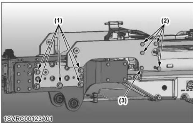
Standard, Deluxe, Premium models (right side)
| (1) (2) | ||
| Size-length M20-60 M20-70 | ||
| Strength division 10.9 | 8.8 | |
| Number of pieces 5 4 | ||
| Tightening torqueN·m (kgf·m) | 568.8(58.0) | 431.5(44.0) |
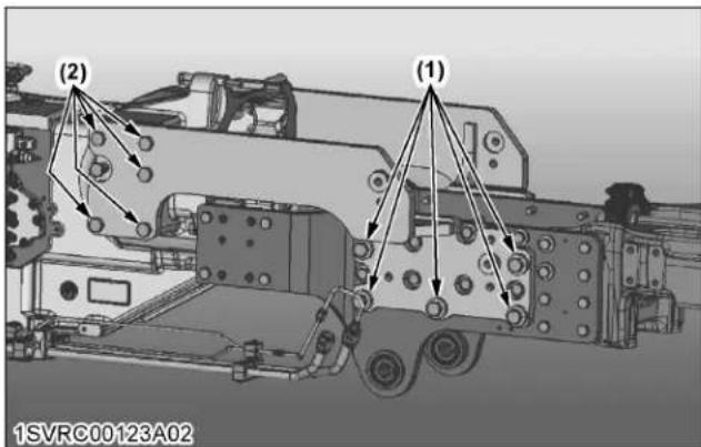
Premium KVT models (left side)
| (1) (2) (3) | |||
| Size-length M20-60 | M20-160 | M20-150 | |
| Strength division | 10.9 8.8 8.8 | ||
| Number of pieces | 5 4 1 | ||
| Tightening torque N·m(kgf·m) | 568.8(58.0) | 431.5(44.0) | 431.5(44.0) |

Premium KVT models (right side)
| (1) (2) (3) | |||
| Size-length M20-60 | M20-160 | M20-240 | |
| Strength division | 10.9 8.8 8.8 | ||
| Number of pieces | 5 4 1 | ||
| Tightening torque N·m(kgf·m) | 568.8(58.0) | 431.5(44.0) | 431.5(44.0) |


DANGER
To avoid personal injury or death:
- Special attention should be made when lifting the load, keep the bucket correctly positioned to prevent spillages.
NOTE :
- Not all risks are listed. Refer to front loader operator's manual.

INSTRUMENT PANEL AND CONTROLS
SWITCHES AND HAND CONTROLS
All models
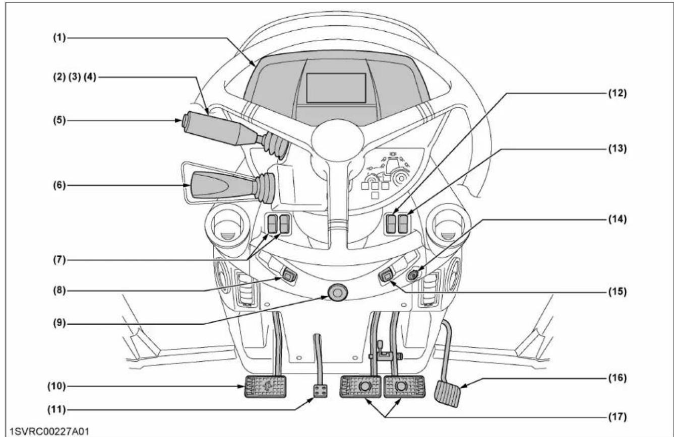
Illustrated contents
(1) Instrument panel 38
(2) Turn signal light switch.... 137
(3) Front wiper and washer switch 221
(4) Headlight beam selection switch 135
136
(5) Horn button 137
(6) Shuttle lever.... 142
(7) Light switch 135
136
(8) DPF inhibit switch 113
(9) Hazard light switch.... 137
(10) Clutch pedal 141
(11) Steering wheel tilt and telescope pedal 134
(12) Battery switch 121
(13) Rear wiper and washer switch.... 221
(14) Key switch.... 125
(15) Parked regeneration switch 115
(16) Foot throttle.... 142
(17) Brake pedals.... 138
INSTRUMENT PANEL
All models

Illustrated contents
(1) Tachometer 167 (6) Coolant temperature gauge 166
(2) DEF/AdBlue® gauge 166 (7) Fuel gauge 166
(3) INDICATORS....60 (8) Front work light switch....137
164 (9) Beacon light switch 138
(4) Liquid crystal display.... 47 (10) Rear work light switch.... 137
(5) Pneumatic pressure gauge (if equipped).... 166 (11) Display switch.... 49
FOOT AND HAND CONTROLS
Standard, Deluxe model
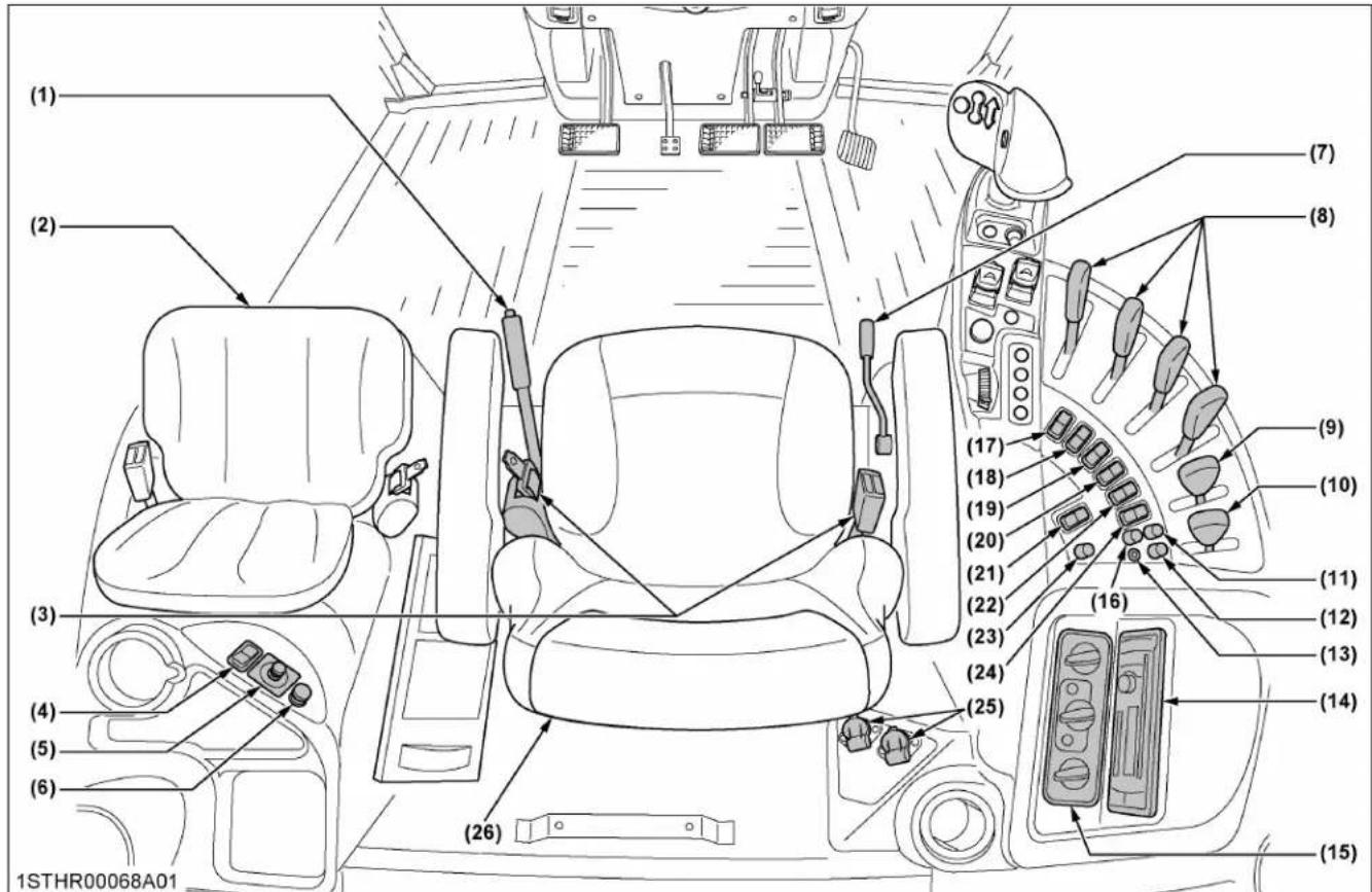
Illustrated contents
(1) Parking brake lever.... 139
(2) Instructional seat (if equipped) 133
(3) Seat belt 132
(4) Heater mirror switch (if equipped).... 134
(5) Remote control mirror switch (if equipped) 135
(6) Cigarette lighter 228
(7) Creep gear shift lever (if equipped) 144
(8) Remote control valve lever 200
(9) PTO operation mode selection lever 176
(10) PTO speed selection lever.... 176
(11) Lift arm top limit adjustment dial 194
(12) 3-point hitch lowering speed adjustment dial.... 195
(13) Lift arm ride control switch 197
(14) Radio and CD player
(15) Air conditioner control panel 223
(16) Draft ratio adjustment dial.... 192
(17) 4WD switch.... 145
(18) Differential lock switch 146
(19) Transmission mode selection switch.... 149
(20) Front suspension mode selection switch (if equipped) 171
(21) Rear defogger switch (if equipped).... 225
(22) Front suspension manual switch (if equipped) 171
(23) Engine rev-limiter control dial 125
(24) Limp home switch 155
(25) Electrical outlet 227
(26) Operator's seat 130
Standard, Deluxe model

Illustrated contents
(1) Auto shift button.... 148
(2) 3-point quick raise and lower switch 196
(3) Shuttle button.... 143
(4) Range gear shift button 148
(5) Shuttle neutral button.... 143
(6) Rear PTO clutch control switch.... 175
(7) Depth control dial (hydraulic dial) 193
(8) Hand throttle 142
(9) Shuttle enable button.... 143
(10) Ez-command center 148
(11) Auto shift sensitivity dial.... 154
(12) Front PTO clutch control switch (if equipped).... 180
(13) 3-point hitch lock button.... 192
(14) Engine RPM memory button.... 126
(15) Engine RPM memory adjustment button 126
Premium model

Illustrated contents
(1) Parking brake lever.... 139
(2) Instructional seat (if equipped) 133
(3) Seat belt....132
(4) Heater mirror switch (if equipped).... 134
(5) Remote control mirror switch (if equipped) 135
(6) Cigarette lighter 228
(7) K-monitor 61
(8) Creep gear shift lever (if equipped) 144
(9) PTO operation mode selection lever 176
(10) PTO speed selection lever.... 176
(11) Radio and CD player
(12) Air conditioner control panel 223
(13) Rear defogger switch (if equipped).... 225
(14) Front suspension manual switch (if equipped) 171
(15) Transmission mode selection switch.... 149
(16) Auto steering switch (if equipped)
(17) Electrical outlet 227
(18) ISOBUS terminal 228
(19) Signal socket 228
(20) Operator's seat 130
Premium model
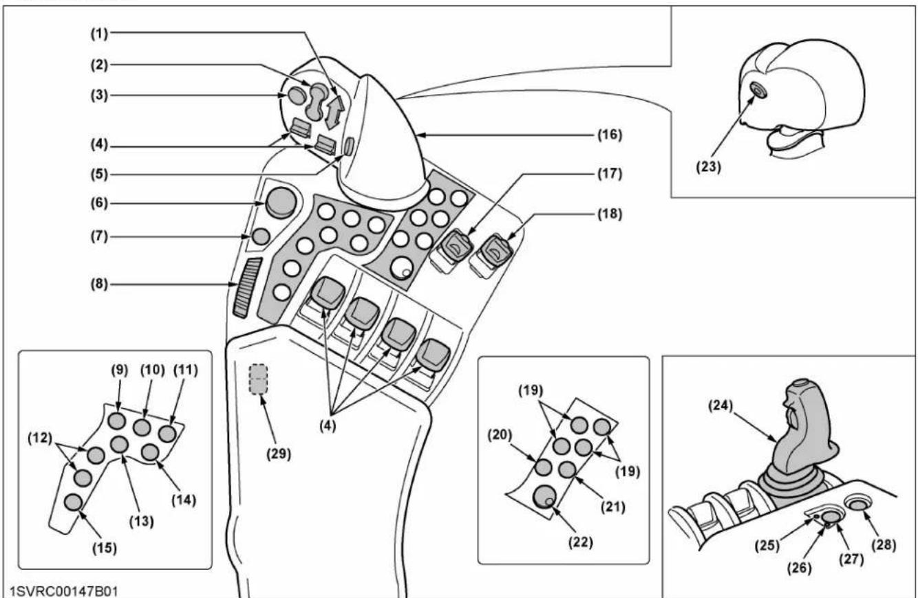
Illustrated contents
(1) Shuttle button.... 143
(2) 3-point quick raise and lower switch 196
(3) Auto shift button.... 148
(4) Remote control valve switch 203
(5) Range gear shift button 148
(6) Depth control dial (hydraulic dial) 193
(7) 3-point hitch lock button....192
(8) Hand throttle 142
(9) Headland management system field out button 88
167
(10) Headland management system field in button 88
167
(11) Shuttle neutral button.... 143
(12) Engine RPM memory button.... 126
(13) Differential lock button 146
(14) 4WD button.... 145
(15) Remote control valve lock button 202
(16) Ez-command center.... 148
(17) Rear PTO clutch control switch.... 175
(18) Front PTO clutch control switch (if equipped).... 180
(19) Function button 66
(20) Esc button....66
(21) Home button 66
(22) Selection dial and button 66
(23) Shuttle enable button.... 143
(24) Joystick for remote control valve and loader (loader mode only) 203
(25) Front loader mode indicator (loader mode only).... 203
(26) Remote control valve mode indicator (loader mode only) 203
(27) Selection button for remote control valve and loader (loader mode only) 203
(28) Joystick lock button (loader mode only).... 203
(29) Limp home switch 155
Premium KVT model

Illustrated contents
(1) Parking brake lever.... 139
(2) Instructional seat (if equipped) 133
(3) Seat belt 132
(4) Heater mirror switch (if equipped).... 134
(5) Remote control mirror switch (if equipped) 135
(6) Cigarette lighter 228
(7) K-monitor 61
(8) PTO operation mode selection lever 176
(9) PTO speed selection lever.... 176
(10) Radio and CD player
(11) Air conditioner control panel 223
(12) Rear defogger switch (if equipped) 225
(13) Front suspension manual switch (if equipped) 171
(14) Auto steering switch (if equipped)
(15) Electrical outlet 227
(16) ISOBUS terminal 228
(17) Signal socket 228
(18) Operator's seat 130
Premium KVT model
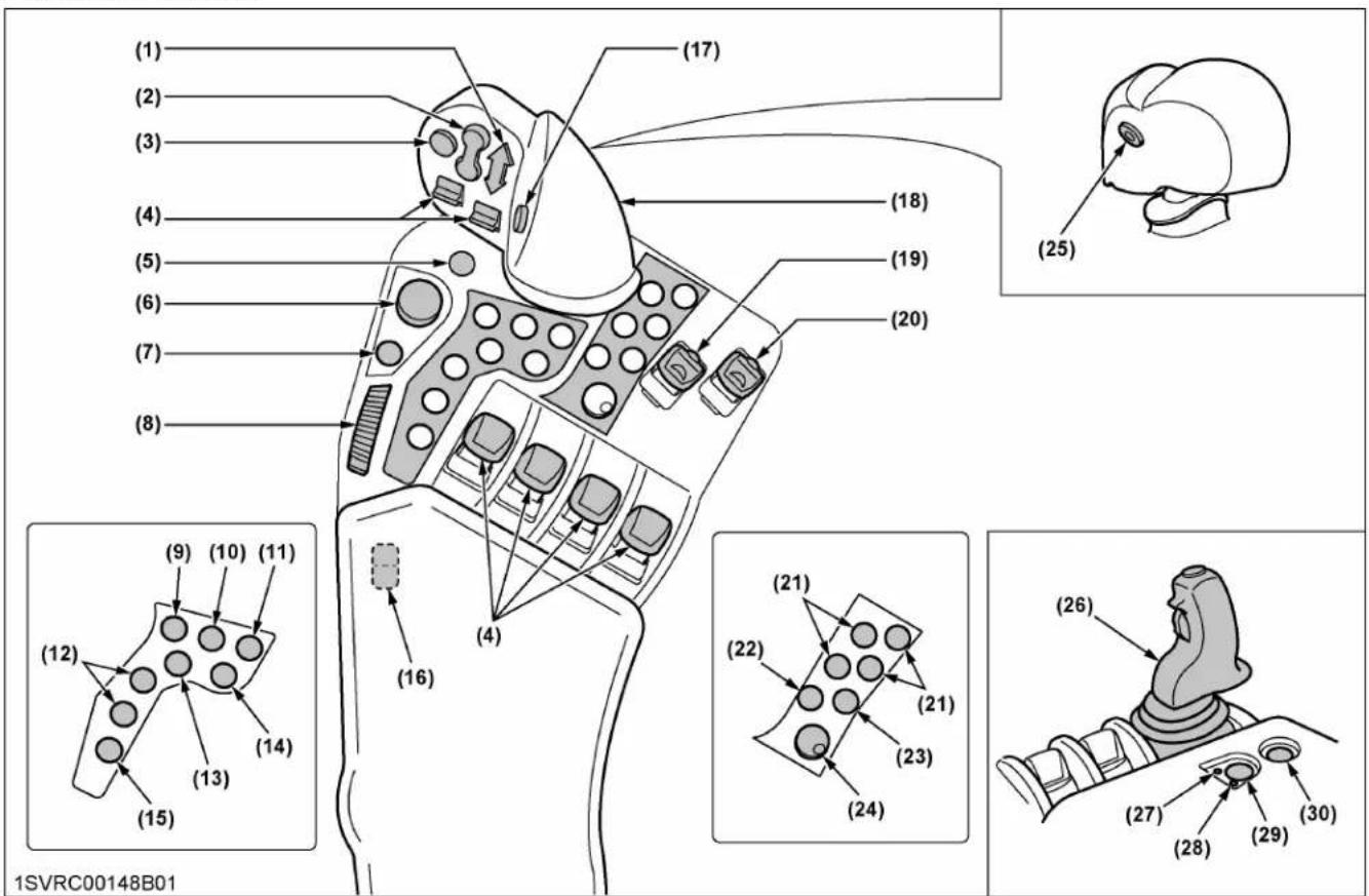
Illustrated contents
(1) Shuttle button.... 143
(2) 3-point quick raise and lower switch 196
(3) Cruise control button.... 161
(4) Remote control valve switch 203
(5) Mode shift button 157
(6) Depth control dial (hydraulic dial) 193
(7) 3-point hitch lock button....192
(8) Hand throttle 142
(9) Headland management system field out button 88
167
(10) Headland management system field in button 88
167
(11) Shuttle neutral button.... 143
(12) Engine RPM memory button.... 126
(13) Differential lock button 146
(14) 4WD button.... 145
(15) Remote control valve lock button 202
(16) Limp home switch 162
(17) Ratio lock button 162
(18) Ez-command center.... 156
(19) Rear PTO clutch control switch.... 175
(20) Front PTO clutch control switch (if equipped).... 180
(21) Function button 66
(22) Esc button....66
(23) Home button 66
(24) Selection dial and button 66
(25) Shuttle enable button.... 143
(26) Joystick for remote control valve and loader (loader mode only) 203
(27) Front loader mode indicator (loader mode only).... 203
(28) Remote control valve mode indicator (loader mode only) 203
(29) Selection button for remote control valve and loader (loader mode only) 203
(30) Joystick lock button (loader mode only).... 203
All models
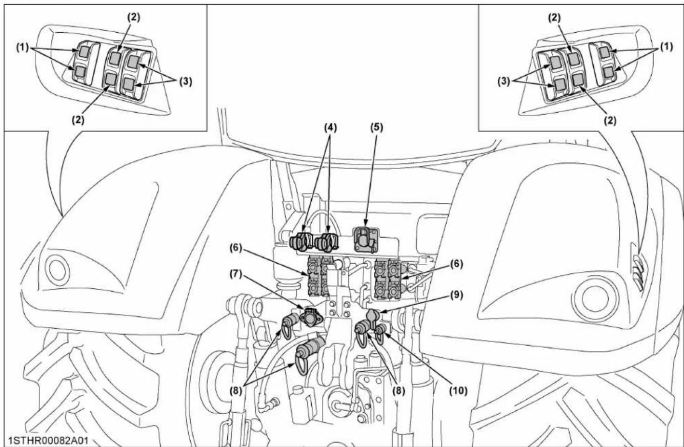
Illustrated contents
(1) External switch for rear PTO.... 176
(2) External switch for remote control valve (2nd segment) (if equipped)
204
(3) External switch for 3-point hitch.... 184
(4) Pneumatic trailer brake (if equipped).... 140
(5) ISOBUS socket (if equipped).... 227
(6) Remote control valve 199
(7) Trailer electrical outlet 226
(8) Hydraulic power beyond port (if equipped) 198
(9) Hydraulic trailer brake (if equipped).... 140
(10) Hydraulic drain port.... 198
INTELLIPANEL™ CONTROL
INSTRUMENT PANEL
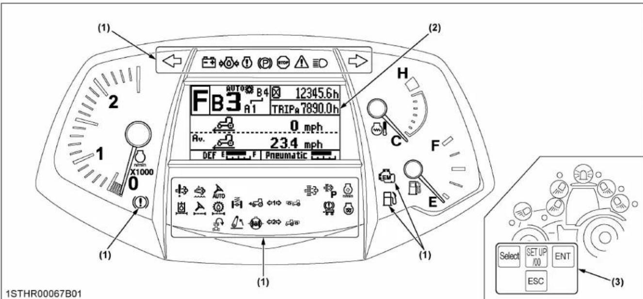
(1) Indicator (2) Liquid crystal display (LCD) (3) Display switch
For Premium and Premium KVT models :
The K-monitor equipped with an LCD touch panel comes in two sizes: 7-inch and 12-inch types. Carefully check the specifications at hand to handle the K-monitor correctly.

(1) K-monitor (7-inch type) (2) K-monitor Pro (12-inch type) - option
LIQUID CRYSTAL DISPLAY (LCD)
This display provides the operator with a variety of information necessary to operate the tractor. Further, part of the display can be modified by the operator as required.

| No. | Description | Refer-ence page | |
| (1) | Power shift model, au-to shift mode (field mode)(C) (D) | (A) Displays [A], [B], [C], [D] or [E]Displays the position of the range gear shift that was selected with the ez-command center.(B) Displays [1], [2], [3], [4], [5] or [6] (reverse: [1], [2] or [3])Displays the position of the currently selected main gear shift [3] that was preset with the automatic gear shift in the field or road mode.(C) Auto shift mode indicatorLights up when the auto shift mode is selected. Stays off while in the manual mode.(D) Auto-shift indicatorDisplays the automatic gear shift range (1 through 4) that was preset with the main gear shift (1 through 6) in the field mode. Lights up when the field mode is selected. Stays off while in the manual mode. | 5080148 |
Power shift model, au-to shift mode (road mode)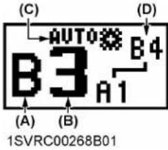 | (A) Displays [A], [B], [C], [D] or [E]Displays the position of the currently selected range gear shift [B] that was preset with the automatic gear shift in the road mode.(B) Displays [1], [2], [3], [4], [5] or [6] (reverse: [1], [2] or [3])Displays the position of the currently selected main gear shift [3] that was preset with the automatic gear shift in the field or road mode.(C) Auto shift mode indicatorLights up when the auto shift mode is selected. Stays off while in the manual mode.(D) Auto-shift indicatorDisplays the automatic gear shift (A1 through B4) that was preset with the main gear shift (1 through 6) and the range gear shift (A through E) in the road mode. Lights up when the road mode is selected. Stays off while in the manual mode. | 5080148 | |
Power shift model, manual mode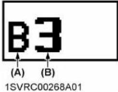 | (A) Displays [A], [B], [C], [D] or [E]Displays the position of the range gear shift that was selected with the ez-command center.(B) Displays [1], [2], [3], [4], [5] or [6] (reverse: [1], [2] or [3])Displays the position of the main gear shift selected with the ez-command center. | 148 | |
(Continued)
| No. | Description | Refer-ence page | |
| (1) | CVT model(E)(F) ^(G)1STHR00075A01 ^(G)1STHR00075A01 | (E) Displays maximum speedThe tractor's travel speed upper limit within a selected mode is displayed.(F) Displays [CRUISE]Operator can see when cruise control is activated.(G) Target speedThe current lever position (speed) with respect to the above upper-limit speed is displayed as a percentage.In the LCD example, the lever is positioned at 40% of the upper-limit speed (15.0 km/h / 9.3 mph). | 85156 |
| (2) | Displays [F], [R] or [N][F] is displayed when forward operation is selected with the shuttle lever or the shuttle button.[R] is displayed when reverse operation is selected with the shuttle lever or the shuttle button.[N] is displayed when the shuttle lever is at neutral position or the shuttle neutral button is pressed. | 142143 | |
| (3) | Basic information monitorOf the 5 types of information, 2 types can be selected by the operator. | 53 | |
| (4) | Performance monitor2 rows of information can be selected by the operator. | 53 | |
| (5) | DEF/AdBlue® gaugeDisplays the fluid level in the DEF/AdBlue® tank. | 166 | |
| (6) | Pneumatic pressure gaugeDisplays the pneumatic pressure (if equipped). | 166 | |
| (7) | Service inspect indicator | ||
 | Service inspect indicator is displayed when the time for an engine oil change has come. 106 | ||
 | Engine low temperature regulation indicator 122 | ||
 | Transmission low temperature regulation indicator 124 | ||
 | Gear shifting warning indicator 163 | ||
 ...... ...... | Engine over speed warning indicator 163 | ||
 | DEF/AdBlue® warning indicator 117 | ||
| (8) | Trouble displayA trouble-spot-pinpointing error code and the related control unit are displayed. | 286 | |
1. LCD initial setting

WARNING
To avoid personal injury or death:
Take the following precautions when starting initial setting.
- Park the machine on firm and level ground.
- Set the parking brake.
- Lower the implement to the ground.
Before operation, make sure the clock and the working range of implement are set.
Once registered, the working range of an implement is put in memory. When the implement is changed to a different one, the latter's working range must be entered anew.
Otherwise, the work area and other data will not be correctly displayed.
1.1 Setting the clock
- Turn on the key switch.
- Press the [SET UP/00] switch, and the setting mode screen appears on the liquid crystal display (LCD) unit.

flowchart
graph TD
    A["Sensor"] --> B["Select"]
    B --> C["SETUP /00"]
    C --> D["ENT"]
    D --> E["ESC"]
    E --> F["1SVRC00063B01"]
    style A fill:#f9f,stroke:#333
    style B fill:#ccf,stroke:#333
    style C fill:#cfc,stroke:#333
    style D fill:#fcc,stroke:#333
    style E fill:#cff,stroke:#333
    style F fill:#ffc,stroke:#333
(1) [SET UP/00] switch
(2) [Select] switch
(3) [ENT] switch
(4) [ESC] switch

(1) Clock setting
(2) Clock display ON/OFF setting
(3) Working range of implement
- When the "Clock setting" has been selected with the [Select] switch and then the [ENT] switch pressed, the clock setting screen shows up.
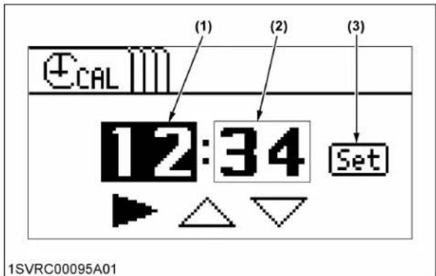
(1) Hour
(2) Minute
(3) Set switch
- Setting the "Hour" of the clock:
a. Select ▶ with the [Select] switch and then press the [ENT] switch to choose the "Hour" (highlighted).
b. To put the clock forward, select ▲ with the [Select] switch and then press the [ENT] switch. The hour continues to change if the [ENT] switch is held down.
c. To put the clock back, select ▼ with the [Select] switch and then press the [ENT] switch. The hour continues to change if the [ENT] switch is held down.
- Setting the "Minute" of the clock:
a. Select ▶ with the [Select] switch and then press the [ENT] switch to choose the "Minute" (highlighted).
b. Carry out the "Minute" setting in the same way as the "Hour" setting.
c. With the "Minute" setting made, select [Set] with the [Select] switch and then press the [ENT] switch. The clock is now completely set and the setting mode screen appears again.
1.2 Setting the clock display ON/OFF
- Press the [Select] switch to choose "Clock ON/OFF setting". Then press the [ENT] switch, and the clock ON/OFF setting screen appears.

(1) Clock ON/OFF setting
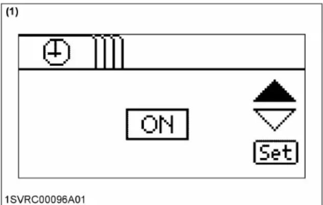
(1) Clock ON/OFF setting screen
- Press the [Select] switch and select ▼ or ▲Then press the [ENT] switch to select clock display ON or OFF.
- Select [Set] with the [Select] switch and then press the [ENT] switch. The ON/OFF setting has been made and the setting mode screen appears again.
1.3 Setting the working range of implement
- Press the [Select] switch to choose "Working range of implement". Then press the [ENT] switch, and
the implement working range setting screen appears.

(1) Working range of implement
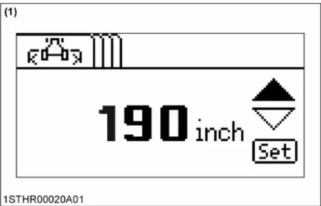
(1) Implement working range setting screen
- Press the [Select] switch and select ▼ or ▲Then press the [ENT] switch, and enter "Working range of implement".
- Select [Set] with the [Select] switch and then press the [ENT] switch. The setting is made and the setting mode screen appears again.
- Press the [ESC] switch, and the normal screen reappears.
2. Setting the power shift transmission (Standard, Deluxe model)
Various settings of the automatic power shift transmission can be made and checked.
2.1 Setting the automatic gear shift (road mode)
Referring to the traveling speeds chart, determine the maximum and minimum gear shifts that are best suited for the job in question.
- Turn on the key switch.
- Press the [SET UP/00] switch to make the setting mode screen appear.

flowchart
graph TD
    A["Select"] --> B["SETUP /00"]
    B --> C["ENT"]
    C --> D["ESC"]
    D --> E["1SVRC00063B01"]
    style A fill:#f9f,stroke:#333
    style B fill:#ccf,stroke:#333
    style C fill:#cfc,stroke:#333
    style D fill:#fcc,stroke:#333
    style E fill:#ffc,stroke:#333
(1) [SET UP/00] switch
(2) [Select] switch
(3) [ENT] switch
(4) [ESC] switch
- Select "Auto shift (road mode)" with the [Select] switch and then press the [ENT] switch.
The auto shift (road mode) setting screen shows up.

1STHR00076A01
(1) Auto shift (road mode)
(2) Auto shift (field mode)
- Select ▶ with the [Select] switch and then press the [ENT] switch to choose the "Range gear shift of minimum traveling speed" (highlighted).
- Select ▼ or ▲ with the [Select] switch and then press the [ENT] switch to determine the desired "Range gear shift of minimum traveling speed" (from A to E).
- Select ▶ with the [Select] switch and then press the [ENT] switch to choose the "Main gear shift of minimum traveling speed" (highlighted).
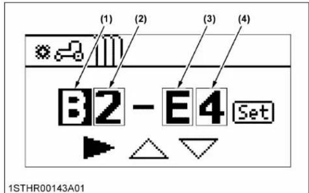
(1) Range gear shift of minimum traveling speed
(2) Main gear shift of minimum traveling speed
(3) Range gear shift of maximum traveling speed
(4) Main gear shift of maximum traveling speed
- Select ▼ or ▲ with the [Select] switch and then press the [ENT] switch to determine the desired "Main gear shift of minimum traveling speed" (from 1 to 6).
- Use the same procedure to determine "Range gear shift and main gear shift of maximum traveling speed".
- Select [SET] with the [Select] switch and then press the [ENT] switch. The setting is made and the setting mode screen appears again.
2.2 Setting the automatic gear shift (field mode)
Referring to the traveling speeds chart, determine the maximum and minimum main gear shifts that are best suited for the job in question.
- Turn on the key switch.
- Press the [SET UP/00] switch to make the setting mode screen appear.

flowchart
graph TD
    A["1SVRC00063B01"] --> B["(1)"]
    B --> C["Select"]
    B --> D["SET UP"]
    B --> E["ENT"]
    C --> F["(2)"]
    D --> G["(3)"]
    E --> H["(4)"]
    H --> I["ESC"]
(1) [SET UP/00] switch
(2) [Select] switch
(3) [ENT] switch
(4) [ESC] switch
- Select "Auto shift (field mode)" with the [Select] switch and then press the [ENT] switch. The auto shift (field mode) setting screen shows up.
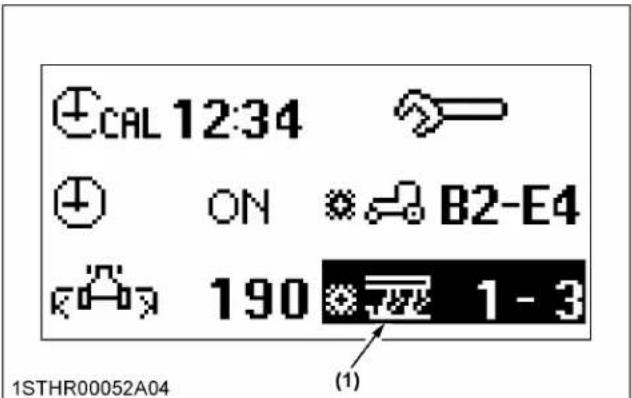
(1) Auto shift (field mode)
- Select ▶ with the [Select] switch and then press the [ENT] switch to choose the "Main gear shift of minimum traveling speed" (highlighted).

(1) Main gear shift of minimum traveling speed
(2) Main gear shift of maximum traveling speed
- Select ▼ or ▲ with the [Select] switch and then press the [ENT] switch to determine the "Main gear shift of minimum traveling speed".
- Select ▶ with the [Select] switch and then press the [ENT] switch to choose the "Main gear shift of maximum traveling speed" (highlighted).
- Select ▼ or ▲ with the [Select] switch and then press the [ENT] switch to determine the "Main gear shift of maximum traveling speed".
- Select [SET] with the [Select] switch and then press the [ENT] switch. The setting is made and the setting mode screen appears again.
3. Basic information monitor and performance monitor
The information required for jobs can be selected and displayed on the LCD screen.
The basic information monitor serves to display 2 of the following 5 types of data.
The performance monitor serves to display 2 types of data picked up from the list below.
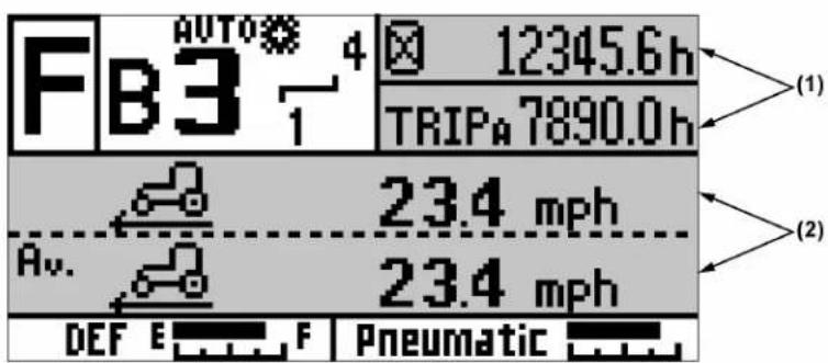
1STHR00050E01
(1) Basic information monitor
(2) Performance monitor
Types of information displayed on the basic information monitor
| Display Remarks | Reference page | ||
 1SVRC00272A01 1SVRC00272A01 | Clock 49 | ||
 1SVRC00272B01 1SVRC00272B01 | Elapsed time (hour meter) — | ||
 1SVRC00272C01 1SVRC00272C01 | Trip A | • Displays the trip measured from the previous resetting.• With the [Trip] displayed and selected, hold down [SET UP/00] switch. The setting goes back to [0.0]. | — |
 1SVRC00272D01 1SVRC00272D01 | Trip B — | ||
 1STHR00113A01 1STHR00113A01 | Travel speed — | ||
Types of information displayed on the performance monitor
| Selected screen | Display Remarks | Reference page | ||
| 1/6 |  | Travel speed | ·The "Average travel speed" is based on the speed since the last reset action was performed.·With the "Average travel speed" displayed and selected, hold down [SET UP/00] switch. The setting goes back to [0.00].NOTE:·The travel speed displayed does not account for wheel slip. | - |
Av. | Average travel speed | - | ||
| [TDK2] | Engine rpm - | |||
 | Memory A rpm 126 | |||
 | Memory B rpm 126 | |||
 | Upper-limit rpm setting | 126 | ||
| 2/6 |  | Instantaneous loading factor | ·The "Average loading factor" is measured based on the loading factor from the previous resetting.·With the "Average loading factor" displayed and selected, hold down [SET UP/00] switch. The setting goes back to [0].·The "Instantaneous loading factor graph" displays the instantaneous loading factor in real time (a bar extending farther to the right shows a higher load). | - |
 | Average loading factor | - | ||
 | Instantaneous loading factor graph | - | ||
 | Rear PTO rpm | 79175 | ||
 | Front PTO rpm (if equipped) | 79180 | ||
 | Instantaneous fuel consumption | ·The "Instantaneous fuel consumption" is measured per hour.·The "Average fuel consumption" is measured per hour from the previous resetting.·With the "Average fuel consumption" displayed and selected, hold down [SET UP/00] switch. The setting goes back to [0.0]. | - | |
| 3/6 | [Y62S] | Average fuel consumption | - | |
 | Mileage graph - | |||
 | Total fuel consumption | ·Displays the total fuel consumption measured from the previous resetting.·The maximum value which can be displayed is 999 gallons or 999 liters.·With the "Total fuel consumption" displayed and selected, hold down [SET UP/00] switch. The setting goes back to [0.0]. | - | |
| [XXC7] | Instantaneous work area fuel consumption | ·The "A verage work area fuel consumption" is measured based on the fuel consumption from the previous resetting.·With the "Average work area fuel consumption" displayed and selected, hold down [SET UP/00] switch. The setting goes back to [0.0].·Preset the implement width. If not preset correctly, incorrect data will be displayed. | 50 | |
 | Average work area fuel consumption | 50 | ||
(Continued)
| Selected screen | Display Remarks | Reference page | ||
| 3/6 |  | Instantaneous work distance fuel consumption | ·The "Instantaneous work distance fuel consumption" is the work distance per fuel consumed. | - |
| 4/6 |  | Average work distance fuel consumption | ·The "A verage work distance fuel consumption" is measured based on the fuel consumption from the previous resetting.·With the "Average work distance fuel consumption" displayed and selected, hold down [SET UP/00] switch. The setting goes back to [0.0]. | - |
 | Instantaneous work area operating efficiency | ·The "Average work area operating efficiency" is measured based on the hourly coverage from the previous resetting.·With the "Average work area operating efficiency" displayed and selected, hold down [SET UP/00] switch. The setting goes back to [0.0].·Preset the implement width. If not preset correctly, incorrect data will be displayed. | 50 | |
 | Average work area operating efficiency | 50 | ||
 | Work area | ·Displays the work area measured from the previous resetting.·With the "Work area" displayed and selected, hold down [SET UP/00] switch. The setting goes back to [0.0].·Preset the implement width. If not preset correctly, incorrect data will be displayed. | 50 | |
 | Odo meter | ·Displays the total mileage of the tractor. The mileage cannot be reset.·The North American models display in "miles", while the other models display in "km". | - | |
 | Travel distance | ·Display the travel distance measured from the previous resetting.·With the "Travel distance" displayed and selected, hold down [SET UP/00] switch. The setting goes back to [0.0]·The North American models display in "feet", while the others models display in "m". | 58 | |
| 5/6 |  | Travel distance | ·Displays the travel distance measured from the previous resetting.·With the "Travel distance" displayed and selected, hold down [SET UP/00] switch. The setting goes back to [0.0].·The North American models display in "miles", while the other models display in "km". | - |
 | DPF temperature | ·Displays the DPF muffler temperature. | 110 | |
 | PM buildup | ·Displays the PM buildup inside the DPF muffler.·Regeneration is needed when the 100% level has been reached.·A bar extending farther to the right shows increased PM. | 110 | |
 | PM buildup graph 110 | |||
 | Cruise control forward speed setting | ·Only Premium KVT model. | 161 | |
 | Cruise control reverse speed setting | 161 | ||
| 6/6 |  | 3-point hitch position | 72190 | |
 | Slip rate | ·The "A verage slip rate" is measured based on the slip rate from the previous resetting.·With the "Average slip rate" displayed and selected, hold down [SET UP/00] switch. The setting goes back to [0.0]. | - | |
(Continued)
| Selected screen | Display Remarks | Reference page | ||
| 6/6 |  | Average slip rate — | ·The “A verage slip rate” is measured based on the slip rate from the previous resetting.·With the “Average slip rate” displayed and selected, hold down [SET UP/00] switch. The setting goes back to [0.0]. | |
 | Travel speed with radar (if equipped) | — | ||
 | Blank | ·Used to delete the information displayed. | — | |
The screen numbers vary with the specifications of tractors.
3.1 Modifying the information displayed on the basic information monitor
- Stop the tractor and apply the parking brake. The display cannot be changed while driving. Trying to make a change while driving will activate the warning buzzer.
- Turn on the key switch.
- Press the [Select] switch to choose "Basic information monitor (1)" (it is highlighted). Then press the [ENT] switch.

flowchart
graph TD
    A["Select"] --> B["SETUP /00"]
    B --> C["ENT"]
    C --> D["ESC"]
    D --> E["1SVRC00063B02"]
    style A fill:#f9f,stroke:#333
    style B fill:#ccf,stroke:#333
    style C fill:#cfc,stroke:#333
    style D fill:#fcc,stroke:#333
    style E fill:#ffc,stroke:#333
(1) [Select] switch
(2) [SET UP/00] switch
(3) [ENT] switch
(4) [ESC] switch

(1) Basic information monitor 1
(2) Basic information monitor 2
- Every time the [Select] switch is pressed, the onscreen data switches among "Hour meter", "Trip A", "Trip B", "Travel speed" and "Clock" in that order. The items being displayed on the basic information monitor (2) are skipped, however.
- Press the [ENT] switch, and the data now on the screen are finalized.
- For the "Basic information monitor (2)", the onscreen data can be modified in the same procedure.
3.2 Modifying the information to display on the performance monitor
- Stop the tractor and apply the parking brake. The display cannot be changed while driving. Trying to make a change while driving will activate the warning buzzer.
- Turn on the key switch.
- Press the [Select] switch to choose "Performance monitor (1)" (it is highlighted). Then press the [ENT] switch. Now the performance monitor select screen shows up.
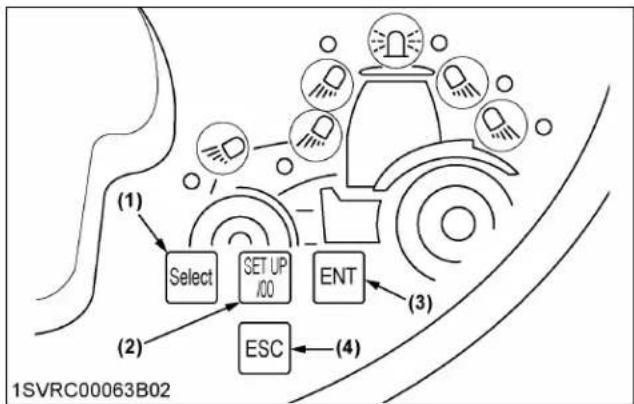
flowchart
graph TD
    A["Select"] --> B["SET UP /00"]
    B --> C["ENT"]
    C --> D["ESC"]
    D --> E["(4)"]
    style A fill:#f9f,stroke:#333
    style B fill:#ccf,stroke:#333
    style C fill:#cfc,stroke:#333
    style D fill:#fcc,stroke:#333
    style E fill:#ffc,stroke:#333
(1) [Select] switch
(2) [SET UP/00] switch
(3) [ENT] switch
(4) [ESC] switch

(1) Performance monitor 1
(2) Performance monitor 2

(1) Screen selector switch
- Using the [Select] switch, get a desired type of information (icon) highlighted. If the desired item (icon) is missing on the LCD screen, select ▲r ▼ with the [Select] switch and then press the [ENT] switch. Another performance monitor screen shows up.
- Press the [ENT] switch, and the data now on the screen are finalized. The selected type of information is now displayed on the performance monitor (1).
- For the "Performance monitor (2)", the onscreen data can be modified in the same procedure.
3.3 Measuring distance
This function serves to measure the distance from your home to the field and other distances.
Preparation
- Stop the tractor and apply the parking brake.
- Turn on the key switch.
- Press the [Select] switch to choose "Performance monitor (1)" or "Performance monitor (2)" (it is highlighted). Then press the [ENT] switch. Now the performance monitor select screen shows up.

flowchart
graph TD
    A["Select"] --> B["SET UP /00"]
    B --> C["ENT"]
    C --> D["ESC"]
    D --> E["(4)"]
    style A fill:#f9f,stroke:#333
    style B fill:#ccf,stroke:#333
    style C fill:#cfc,stroke:#333
    style D fill:#fcc,stroke:#333
    style E fill:#ffc,stroke:#333
(1) [Select] switch
(2) [SET UP/00] switch
(3) [ENT] switch
(4) [ESC] switch

(1) Performance monitor 1
(2) Performance monitor 2
- Using the select switch, get the distance measuring icon highlighted. Press the [ENT] switch. The distance measuring icon is now displayed on the performance monitor.
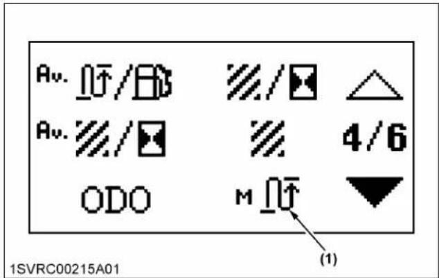
(1) Distance measuring icon

(1) Distance measuring
How to measure distance
- Press the [Select] switch to select the distance measurement icon on the meter panel (highlighted). In that state, press and hold the [ENT] switch to enable distance measurement.
- Press the [ENT] switch to start distance measurement. Press the [ENT] switch again to stop distance measurement.
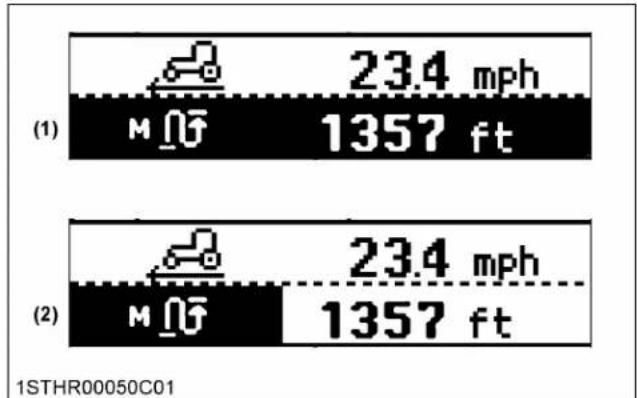
bar
| Panel | Metric | Value | |---|---|---| | (1) | M ∅F | 23.4 mph | | (1) | 1357 ft | 1357 ft | | (2) | M ∅F | 23.4 mph | | (2) | 1357 ft | 1357 ft | 1STHR00050C01(1) "Distance measurement stopped"
(2) "Measurement distance"
- To reset the measured value to zero, press and hold the [SET UP/00] switch while distance measurement is enabled.
- Press [ESC] switch to return to the normal screen and stop distance measurement. Also, after stopping distance measurement, the measured value can be reset to zero by holding down the [SET UP/00] switch while the distance measurement icon on the performance monitor in the meter panel is selected.
INDICATORS
Before operating the tractor, fully understand the meanings of the indicators. If anything is unclear, carefully reread the reference pages.
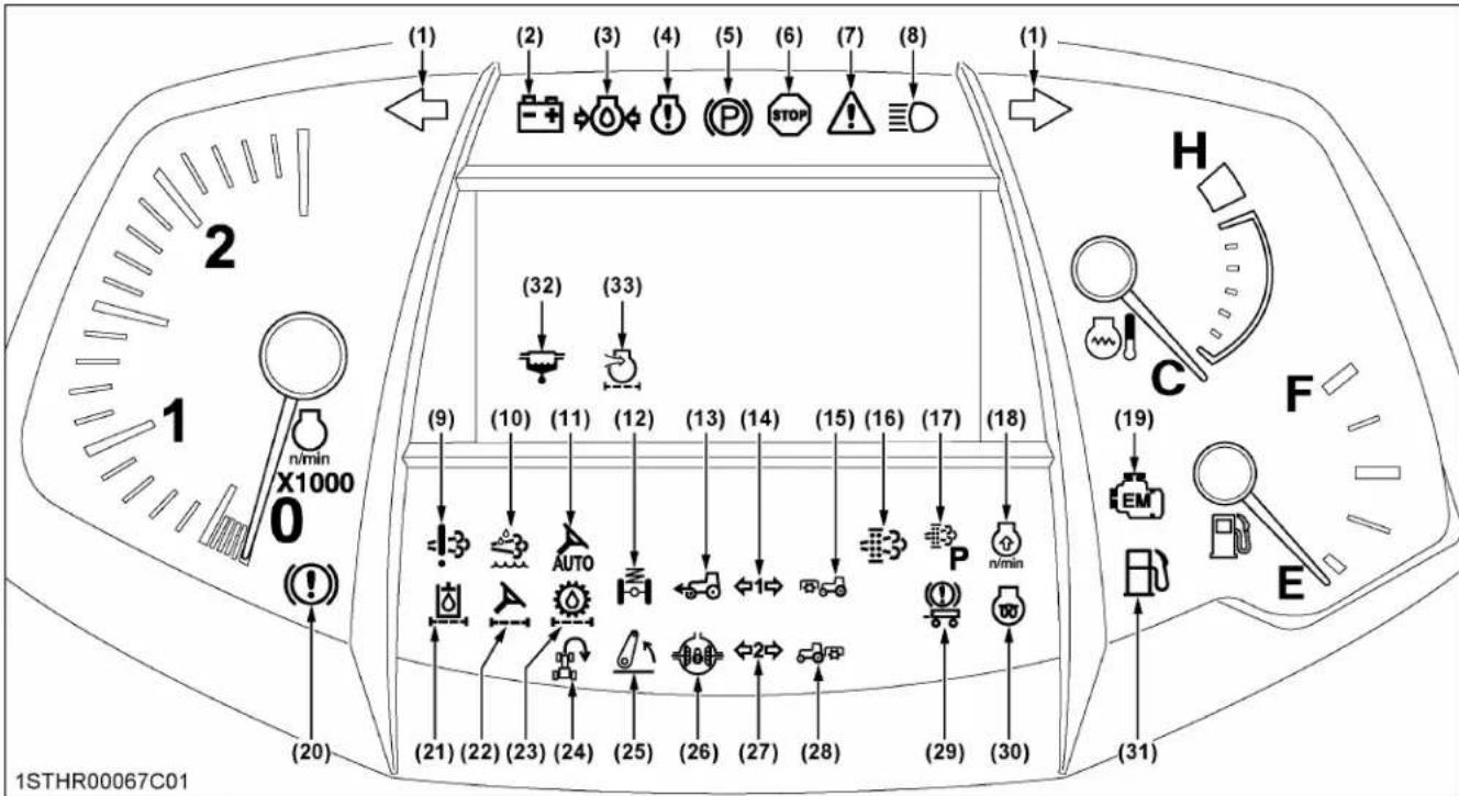
Illustrated contents
(1) Turn signal and hazard light indicator 137
(2) Electrical charge warning indicator 164
(3) Engine oil pressure warning indicator.... 164
(4) Engine warning indicator 164
(5) Parking brake warning indicator 139
164
(6) Master system warning indicator 164
(7) System abnormality indicator.... 164
(8) High-beam indicator.... 135
136
(9) DEF/AdBlue ® system warning indicator ....117
164
(10) DEF/AdBlue® warning indicator....117
164
(11) Auto steer indicator
(12) Front suspension indicator.... 172
(13) 4WD indicator 145
(14) Trailer indicator 1 137
(15) Front PTO indicator.... 180
(16) Regeneration indicator....110
(17) Parked regeneration indicator....115
(18) Engine rpm increase indicator 111
(19) Emission indicator.... 164
(20) Brake oil pressure warning indicator.... 164
(21) Hydraulic oil filter (suction) indicator 164
(22) Power steering oil filter indicator.... 164
(23) Transmission oil filter indicator.... 164
(24) Headland management system indicator 88
167
(25) 3-point hitch lifting and lowering indicator.... 196
(26) Differential lock indicator 146
(27) Trailer indicator 2 137
(28) Rear PTO indicator 175
(29) Trailer brake warning indicator.... 141
(30) Heater indicator 122
(31) Fuel level indicator 164
(32) Water separator indicator.... 164
(33) Air cleaner indicator 164
NOTE :
- The water separator indicator (32) and air cleaner indicator (33) are displayed on the LCD when the trouble occurs.
1. Indicator color
Most indicators light up in the following 3 colors for identification.
Green indicator
This color indicates that the operation-related control switches and levers are enabled or disabled.
Amber indicator
This color means that the tractor's operating condition is being monitored.
If amber indicator lights up or starts blinking, resolve the cause of the trouble as required.
Red indicator
This color gives a warning directly linked to the possibility of injuries and/or machine troubles.
If red indicator lights up or starts blinking, immediately resolve the cause of the trouble.
K-MONITOR MAIN MENU (PREMIUM AND PREMIUM KVT MODELS ONLY)
This chapter covers the handling and operation of the "Main menu" that is routinely used.
Details regarding the use of the sub-menu can be found in a different section.
(See K-MONITOR SUB-MENU (PREMIUM AND PREMIUM KVT MODELS ONLY) on page 102.)
On the panel, detailed settings of the differential lock, PTO, remote control valve and other functions can be made and checked. Once any setting has been made, it can also be redisplayed immediately using the function buttons. When the implement-related ISOBUS connector and the optional live view camera are connected, this panel serves as their monitor screen.
1. Names of parts and their handling (K-monitor)

(1) Screen switch
(2) ISOBUS emergency shut-off switch
(3) Main menu select switch
(4) USB port
(5) LAN port
(6) External camera input terminal (S terminal)
(7) Sub-menu select icon
(8) Sub-menu display switch
Main menu select switch
- Press the main menu select switch, and various types of information get displayed.
- Referring to the following list, select your required type of information.
If the sub-menu display switch (10) is selected, the sub-menu icons get displayed on the left of the screen.
(1)

(6)
(2)
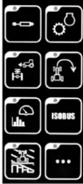
(7)
(3)

(8)
(4)

(9)
1SVRC00102A01
(1) 3-point hitch
(2) Remote control valve
(3) Drivability
(4) Operating conditions
(5) GEOCONTROL
(6) PTO
(7) Engine and transmission
(8) Headland management system
(9) ISOBUS
(10) Sub-menu
Screen switch
- Touch the switch to switch between screen ON and screen OFF.
Turn the screen OFF for night driving, and so on.
ISOBUS emergency shut-off switch
- With an ISOBUS-compatible implement in motion, press this switch to stop the implement in case of emergency. Emergency stop methods vary according to the type of implement. For details, check with the instruction manual of the implement in question.
2. Names of parts and their handling (K-monitor Pro)

(1) ISOBUS emergency shut-off switch
(2) Sub-screen display
(3) Screen switch
(4) Sub-menu select icon
(5) Main display screen
(6) Main menu select icon
(7) LAN port
(8) USB port
(9) External camera input terminal (S terminal)
(10) Microphone and earphone terminals
Main menu display
On the screen, 4 different main menus that are routinely used can be displayed. They may also be switched over easily.
Displaying and switching procedure
- Going to the main display screen:
Touch the main menu icon you want to display, and touch the main display screen.
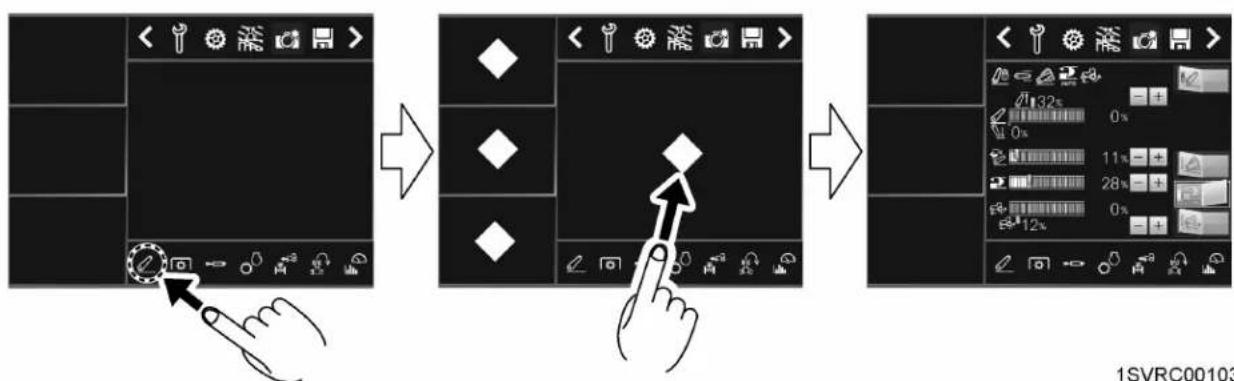
flowchart
graph LR
    A["Start: Click Button"] --> B["Arrow to Button"]
    B --> C["Arrow to Display Panel"]
    C --> D["Next Step: Adjustment with Arrow"]
    D --> E["End: Display Panel with 12x zoom and 0x tolerance"]
- Going to the sub-display screen:
Touch the main menu icon you want to display, and touch the sub-display screen.

flowchart
graph TD
    A["Start: Tool Icon"] --> B["Step 1: Click Button"]
    B --> C["Step 2: Click Button with Diamond"]
    C --> D["Step 3: Click Button with Diamond"]
    D --> E["End: Screen with Tools and Settings"]
    style A fill:#f9f,stroke:#333
    style B fill:#ccf,stroke:#333
    style C fill:#cfc,stroke:#333
    style D fill:#fcc,stroke:#333
    style E fill:#cff,stroke:#333
- Switching between the sub-display screen and main display screen:
Touch the sub-display screen you want to display on the main display screen, and touch the main display screen.

flowchart
graph TD
    A["Tool selection interface"] --> B["Parameter input: 86, 10x, 40x, 10x, 2400, 1040, 2200"]
    B --> C{Control buttons: F, N, R, A1}
    C --> D["Output: 1STHR00022A01"]
- Storing the sub-display screen into the main menu:
Touch the sub-display screen to store, and touch the main menu area.

flowchart
graph TD
    A["Start: Device Control Panel"] --> B["Step 1: Usage Indicator"]
    B --> C["Step 2: Status Indicator"]
    C --> D["End: Display Panel"]
Screen switch
Touch the switch to switch between screen ON and screen OFF.
Turn the screen OFF for night driving, and so on.
ISOBUS emergency shut-off switch
With an ISOBUS-compatible implement in motion, press this switch to stop the implement in case of emergency. Emergency stop methods vary according to the type of implement. For details, check with the instruction manual of the implement in question.
3. Basic procedures
The following figure shows an example in which "3-point hitch" is selected from the main menu.

bar
| Category | Value (%) | |---|---| | Group 1 | 32 | | Group 2 | 0 | | Group 3 | 11 | | Group 4 | 28 | | Group 5 | 0 | | Group 6 | 12 |1SVRC00157K01
(1) Indicator
(2) Setting change switches
(3) Select switches
(4) Setting display bar graphs
Familiarize yourself with the basic procedures, such as changing the settings, as follows:
• Changing the screen settings on page 67
• [F] buttons on page 68
• Function of the "Home" button on page 68
• Function of the [ESC] button on page 68
3.1 Changing the screen settings
To change the settings on each screen, use any of the following procedures:
- Touch the [-] or [+] button.
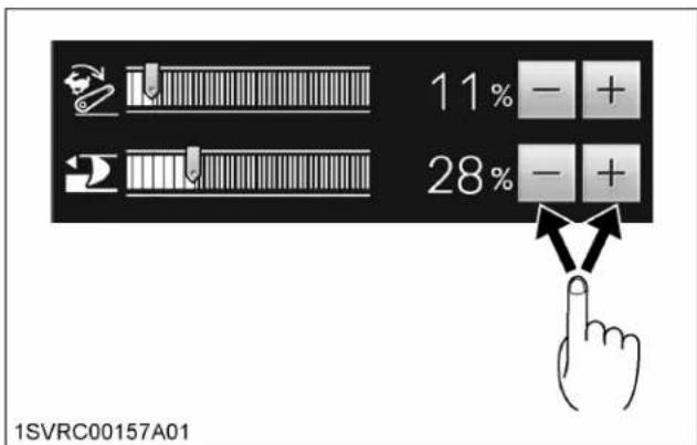
- Touch a target point on the bar graph, and the slider of the graph will move to the touched point.

- Touch the right or left side of the setting-pointing slider, and the slider will move to the touched point.
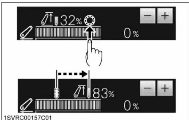
- Use the selection dial and button.

(1) Selection dial and button
a. Turn the selection dial and button until the orange selected frame reaches the desired item.
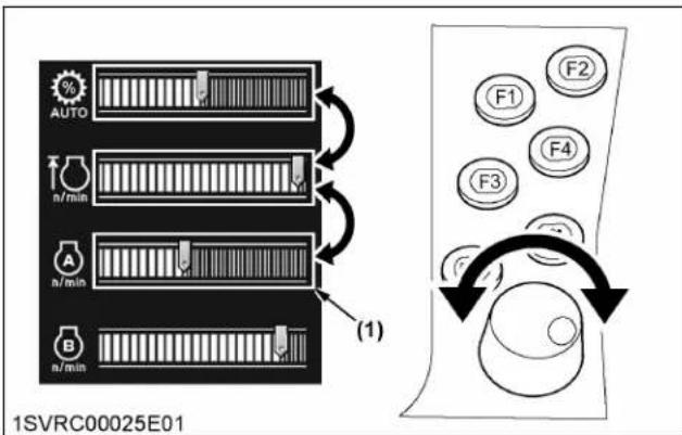
(1) Orange selected frame
b. Press the selection dial and button to make a selection. The orange selected frame turns yellow-green, which means the editing mode.
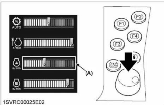
(A) Orange selected frame turns yellow-green
c. Turn the selection dial and button clockwise or counterclockwise to change the setting.

d. Press the selection dial and button to complete the setting. Now the new setting is effective.

(A) Yellow-green selected frame turns orange
- To cancel a new item or a new setting, just press the [ESC] button.
3.2 [F] buttons

(1) [F] button
Function
Routinely-used setting screens can be programmed to the buttons [F1] through [F4].
Regardless of the information currently displayed, just press an [F] button and the allocated setting screen appears.
You can modify and check the settings quickly.
Press the [F] button again, and the previous screen comes back.
Allocation
- Select the setting screen for allocation and hold down any of the [F1] through [F4] buttons 2 seconds or longer to allocate that screen.
3.3 Function of the "Home" button

(1) "Home" button
- Hold down this button for 2 seconds, and your preset "Home" screen appears again. If you have purchased the tractor but its "Home" screen has not been made yet, the factory-set "Engine, transmission" screen reappears.
- Hold down this button between 2 and 4 seconds, and the currently shown screen replaces the "Home" screen.
- Hold down this button longer than 4 seconds, and the same "Home" screen as at the time of purchase is resumed.
3.4 Function of the [ESC] button

(1) [ESC] button
- Press this button, and the previous screen reappears. This works in the same way as with the "Previous screen resume" switch.
4. System basic settings
The screen brightness, sound volume and other settings can be adjusted. Modify those settings as required.
4.1 Calling up the setting screen (K-monitor)
- Touch the sub-menu display switch to make the sub-menu appear.
- Using the sub-menu scroll switch, make the gear mark icon appear. Touch this icon, and the system settings screen shows up.

(1) Sub-menu display switch
(2) Sub-menu scroll switch
(3) Gear mark icon
4.2 Calling up the setting screen (K-monitor Pro)
- Using the sub-menu scroll switch, make the gear mark icon appear.
- Touch the gear mark icon first and then the main display screen, and the system settings screen shows up.

(1) Sub-menu scroll switch
(2) Gear mark icon
4.3 Setting items and adjusting the setting mode screen
Touch the arrow switch to switch screens among "system settings (1)", "system settings (2)", "Time/ Date settings", "ISOBUS settings" and "Licenses" in that order.
4.3.1 System settings (1) screen
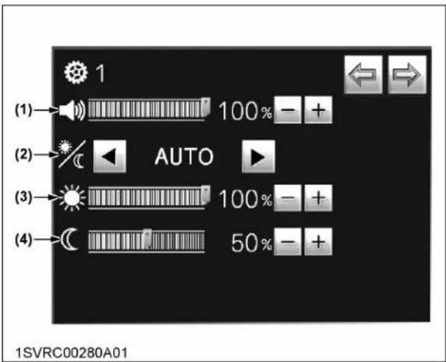
(1) Sound volume
(2) Screen brightness
(3) Daytime mode screen brightness
(4) Nighttime mode screen brightness
Sound volume
Slide the graph farther to the right to increase the volume.
Screen brightness
The brightness level can be selected from the following settings:
- Sun icon: Daytime mode
• Moon icon: Nighttime mode
• AUTO: Automatic daytime and nighttime switching mode
Daytime mode screen brightness
Slide the graph farther to the right to increase the brightness.
Nighttime mode screen brightness
Slide the graph farther to the right to increase the brightness.
4.3.2 System settings (2) screen
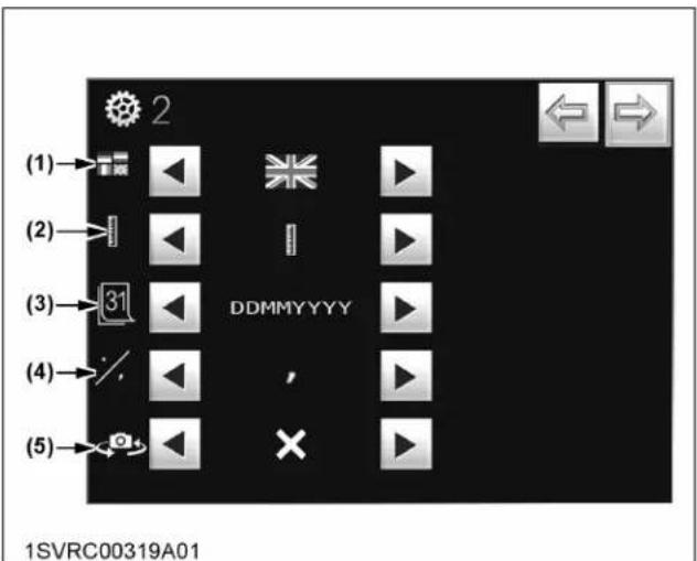
(1) Languages
(2) Unit system
(3) Setting year, month, and date
(4) Decimal marker setting
(5) Live view camera display switching
Languages
There are 9 languages to choose from: English, Dutch, German, French, Italian, Spanish, Polish, Portuguese and Japanese.
Unit system
The unit system can be chosen from the following settings:
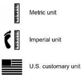
Setting year, month, and date
The year, month, and date display can be selected from the following:
- DDMMYYYY
• DDYYYYMM - MMYYYYDD
• MMDDYYYY
• YYYYMMDD
• YYYYDDMM
Decimal marker setting
The choice is between [,] (comma) and [.] (period).
Live view camera display switching
Live view camera display can be chosen from the following settings:
• [X]: When the camera is installed for front view.
• [V]: When the camera is installed for rear view.
4.3.3 Time and date settings screen

(1) Time
(2) Date
(3) Confirm switch
(4) Cancel switch
Time
Set "Hour", "Minute" and "Second" and press the confirm switch.
Touch the cancel switch to cancel.
Date
Set "Day", "Month" and "Year" and press the confirm switch.
Touch the cancel switch to cancel.
4.3.4 ISOBUS settings screen
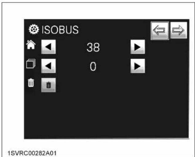
Do not change the setting of this screen.
For details, consult your local KUBOTA Dealer.
4.3.5 License confirmation screen

Setting is required when options are attached. For details, consult your local Kubota Dealer.
5. Setting the 3-point hitch
On the following menu, the 3-point hitch height and lowering speed, automatic draft control, position control, and ride control can be preset.
With the optional radar device in place, the slip control is also enabled.

(1) 3-point hitch lock indicator
(2) 3-point hitch status indicator
(3) Ride control indicator
(4) Auto draft mode indicator
(5) Wheel slip control indicator
(6) 3-point hitch lock switch
(7) Ride control switch
(8) Auto draft mode switch
(9) Wheel slip control switch
(10) Plus (+) switch
(11) Minus (-) switch
(12) Wheel slip control
(13) Draft sensitivity control
(14) 3-point hitch lowering speed control
(15) Lift arm bottom limit control
(16) Lift arm height control, current position (height)
(17) Lift arm top limit control
Switching between 3-point hitch lock and unlock
Touch the left half of the 3-point hitch lock switch (6), and the 3-point hitch gets locked. A touch on the right half unlocks the 3-point hitch.
While it is locked, the indicator (1) lights up and stays on.
Adjusting the lift arm top limit control (17)
Touch the "Plus (+)" switch (10) or the "Minus (-)" switch (11) on the right side of the lift arm top limit control (17) to readjust the top limit height.
Raise the percentage to increase the top limit.
When it has reached 100%, the top limit setting is canceled.
Adjusting the lift arm bottom limit control (15)
Using the depth control dial (hydraulic dial), the bottom limit height can be readjusted.
Lower the percentage to decrease the bottom limit.
When the auto draft mode switch (8) is ON, the lower link lowering position varies according to the draft sensitivity control (13) setting value.
Displaying the lift arm height (16)
The current lift arm position (height) is automatically displayed with the bar graph and percentage.
A higher percentage shows a higher 3-point hitch height.
Adjusting the 3-point hitch lowering speed control (14)
Extend the graph farther to the right (raise the percentage) to increase the lowering speed.
Switching the automatic draft control
Touch the left half of the auto draft mode switch (8), and the automatic draft control gets activated. A touch on the right half deactivates it.
If a “lowering” action is made with the depth control dial (hydraulic dial) or the 3-point quick lower switch in the automatic draft control mode, the indicator (4) lights up and stays on.
Adjusting the draft sensitivity control (13)
Extend the graph farther to the right (raise the percentage) to increase the draft sensitivity. Depending on the type of job, readjust the draft sensitivity.
If the draft sensitivity is set at 0%, the position control works instead.
Setting the ride control
Touch the left half of the ride control switch (7), and the ride control gets activated. A touch on the right half deactivates it.
The ride control unit serves to absorb vibrations and shocks upon the tractor, when the machine is moved equipped with a 3-point-hitched implement.
The ride control unit activates itself if the 3-point quick raise switch is pressed to bring the rear hitch up to its top limit and the traveling speed rises above 6 km/h (3.7 mph).
Setting the wheel slip control (9)
Used together with the optional radar device, the tractor can be constantly kept under the best control. This helps to improve your productivity.
For details, contact your local KUBOTA Dealer.
3-Point hitch status indicator (2)
The control status of the 3-point hitch is displayed all the time with the following indicators:

(1) Blocked (neutral)
(2) Float
(3) Transport
(4) Work
6. Setting the remote control valve
In the following figure, the settings of all the remote control valves can be checked.

1SVRC00263B01
(1) Collective remote control valve lock indicator
(2) Collective remote control valve lock switch
(3) Individual remote control valve lock/unlock switch
(4) Valve operating time
(5) Discharge rate from cylinder (retract) port
(6) Discharge rate from cylinder (extend) port
(7) Valve operating status indicator
(8) Priority valve indicator
(9) Timer mode indicator
(A) The priority flow from the hydraulic pump is set for the first remote control valve.
(B) The automatic shut-off timer of the second remote control valve is set at ON.
(C) The preset oil flow rate to each implement (remote control cylinder) is displayed. The third remote control cylinder remains locked, which means that no oil is flowing.
(D) The automatic shut-off timer (time) of remote control is displayed.
(E) Valve action status indicator
Valve action status indicator
The oil flow to the implement (remote control cylinder) is indicated with the following icons:

(1) Extend
(2) Retract
(3) Blocked (neutral)
(4) Float
(5) Lock
Modifying the settings
- If you want to modify any of the settings, touch the "graph" of the relevant valve. In so doing, the "detailed settings of remote control valve" screen shows up.
(See Detailed settings of remote control valve on page 76.)
- Touch the left half of the collective remote control valve lock switch, and all the remote control valves are collectively locked and the implement cannot be raised and lowered.
A touch on the right half unlocks all the valves.
In locked status, the collective remote control valve lock indicator also lights up.
6.1 Detailed settings of remote control valve
Each of the valves can be individually preset in detail, but only one can be set for priority flow.

1SVRC00264B01
(1) Remote control valve operating status indicator
(2) Priority flow status indicator
(3) Automatic shut-off timer indicator
(4) Remote control valve number
(5) Previous screen resume switch
(6) Remote control valve lock/unlock switch
(7) Priority flow status on/off switch
(8) Automatic shut-off timer on/off switch
(9) Plus (+) switch
(10) Minus (-) switch
(11) Automatic shut-off timer control
(12) Discharge rate from cylinder (retract) port control
(13) Discharge rate from cylinder (extend) port control
- Display the valve number (4) to be set in detail.
- To ensure the priority flow for the valve 1, touch the left half of the priority flow status on/off switch (7). A touch on the right half clears this setting.
Once the priority flow is ensured, the indicator (2) lights up and stays on.
- To set the automatic shut-off timer, touch the left half of the automatic shut-off timer on/off switch (8). A touch on the right half clears this setting.
Once the timer is ensured, the indicator (3) lights up and stays on.
-
To lock the remote control valve, touch the left half of the remote control valve lock/unlock switch (6). A touch on the right half clears this setting.
-
Touch the switch (5), and the previous screen reappears.
Setting the oil flow rate and timer
- To adjust the oil flow rate for the implement (remote control cylinder), use the "Plus (+)" switch (9) and the "Minus (-)" switch (10).
Raise the percentage to increase the oil flow rate.
- The timer may be preset up to 60 seconds.
If the timer is set to infinity ( ∞ ), the remote control valve will go into continuous operation.
NOTE :
- When you have moved the remote control valve switch or lever to the "raise" or "lower" position and then released your hand from the switch or lever, the timer gets activated. When the set time is over, the oil flow to the implement is interrupted. After this stage, the timer can be set only with the switch or lever.
- If during an action the switch or lever is moved in the reverse direction, the timer setting is cancelled.
7. Setting the drivability
The differential lock, front wheel drive and front suspension settings can be made.
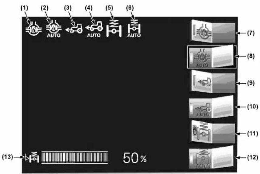
1SVRC00265B01
(1) Differential lock indicator
(2) Auto differential lock indicator
(3) 4WD indicator
(4) Auto 4WD indicator
(5) Front suspension (active) indicator
(6) Front suspension (auto) indicator
(7) Differential lock switch
(8) Auto differential lock switch
(9) 4WD switch
(10) Auto 4WD switch
(11) Front suspension (block) switch
(12) Front suspension (auto) switch
(13) Front suspension level meter
Setting the differential lock
- Touch the left half of the differential lock switch (7), and the differential of the full-time front and rear wheels gets locked. The indicator (1) lights up and stays on.
- Turn off the switch (7), and the differential gets unlocked and the indicator (1) goes off.
- Touch the left half of the auto differential lock switch (8), and the automatic differential, listed below, gets locked. The indicator (2) lights up and stays on.
- Turn off the switch (8), and the differential gets unlocked and the indicator (2) goes off.
Operating conditions of the automatic differential lock:
| Traveling speed Front wheel turning angle 4-wheel differential lock | ||
| Below 10 km/h (6.2 mph) | Approx. 15° or less ON | *1 |
| Approx. 15° or more OFF | ||
| Between approximately 10 and 20 km/h (6.2 and 12.4 mph) | Approx. 10° or less ON | *1 |
| Approx. 10° or more OFF | ||
| Above 20 km/h (12.4 mph) --- OFF | ||
*1 Step on one of the brake pedals, and the differential lock is released.
Setting the front wheel drive
- Touch the left half of the 4WD switch (9), and the front and rear wheels are driven. The indicator (3) lights up and stays on.
- Turn off the switch (9), and the front-wheel drive is disabled and the indicator (3) goes off.
- Touch the left half of the auto 4WD switch (10), and the automatic 4WD, listed below, gets activated. The indicator (4) lights up and stays on.
- Turn off the switch (10), and the 2WD is abled and the indicator (4) goes off.
Operating conditions of the automatic 4WD:
| Traveling speed Front wheel turning angle Front wheel drive | ||
| Below 10 km/h (6.2 mph) | Approx. 15° or less ON | |
| Approx. 15° or more OFF | ||
| Between approximately 10 and 20 km/h (6.2 and 12.4 mph) | Approx. 10° or less ON | |
| Approx. 10° or more OFF | ||
| Above 20 km/h (12.4 mph) — OFF | ||
Setting the front suspension
- The front suspension is chosen from the "Auto", "Block" and "Manual" modes.
- Touch the left half of the auto switch (12), and the automatic mode is selected. The auto indicator (6) lights up and stays on, whereas the indicator (5) goes off.
- Touch the left half of the block switch (11), and the block mode is selected. The active and auto indicators (5 and 6) both go off.
- Using the manual control switch at the operator's seat, the manual mode may be enabled. In the manual mode, the suspension cylinder's extension status can be checked on the level meter (13). (See FRONT SUSPENSION (IF EQUIPPED) on page 170.)
8. Setting the PTO
Automatic ON/OFF setting of PTO shaft revolutions, which is interlocked with the lifting height of the rear 3-point-hitched implement, can be made.

WARNING
To avoid personal injury or death:
- Use caution when setting auto engagement, considering type of implement in use.

1SVRC00266B01
(1) Front PTO indicator
(2) Front PTO rpm
(3) Rear PTO indicator
(4) Rear PTO rpm
(5) Height at which the PTO turns on when the implement is lowered
(6) Auto PTO switch
(7) Plus (+) switch
(8) Minus (-) switch
(9) Height at which the PTO turns off when the implement is raised
(10) Current lift arm height
(11) Auto PTO indicator
Setting the 3-point-hitch-interlocked PTO function
-
Start the engine and start PTO rotation.
-
Touch the left half of the auto PTO switch (6), and the 3-point-hitch-interlocked PTO function is enabled. A touch on the right half disables this function.
While the 3-point-hitch-interlocked PTO function is on, the indicator (11) lights up and stays on.
Setting the height at which the PTO restarts turning when the implement is lowered
- Touch the "Plus (+)" switch (7) or "Minus (-)" switch (8) on the right side to readjust the height at which the PTO shaft restarts turning.
Raise the percentage to raise the height at which turning restarts.
Setting the height at which the PTO stops turning when the implement is raised
- Touch the "Plus (+)" switch (7) or "Minus (-)" switch (8) on the left bottom to readjust the height for the PTO shaft to stop turning.
Lower the percentage to lower the height at which turning stops.
Displaying the PTO rpm
- With the PTO switch at ON (engage), the front PTO rpm (2) as well as the rear PTO rpm (4) are displayed.
9. Setting the engine and power shift transmission (Premium model only)

1SVRC00294A01
(1) Engine RPM memory (A/B) indicator
(2) Auto shift mode (road/field) indicator
(3) Shuttle lever indicator
(4) Auto shift range indicator for road mode
(5) Field mode setting switch
(6) Road mode setting switch
(7) Engine RPM memory (A) switch
(8) Engine RPM memory (B) switch
(9) Plus (+) switch
(10) Minus (-) switch
(11) Engine RPM memory (B) control
(12) Engine RPM memory (A) control
(13) Rev-limiter control
(14) Auto shift sensitivity control
(15) Engine rpm
Various settings of the automatic power shift transmission can be made and checked, as follows:
- Setting the traveling speed gear in the road mode on page 81
- Setting the traveling speed gear in the field mode on page 81
- Setting the auto shift sensitivity on page 83
Further, the engine rev-limiter, engine rpm memory and other settings may be also set, as follows:
- Setting the engine rev-limit on page 84
- Setting the engine rpm memory on page 84
9.1 Setting the traveling speed gear in the road mode
- Touch the road mode setting switch, and the "road mode" traveling speed gear setting screen shows up.
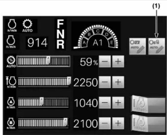
1SVRC00294E02
(1) Road mode setting switch
- Referring to the traveling speed chart, determine maximum and minimum traveling speeds.
- Setting the maximum speed gear shift: Using the high-speed setting switch, preset the desired traveling speed (the high-speed slider moves to the set position).
- Setting the minimum speed gear shift: Using the low-speed setting switch, preset the desired traveling speed (the low-speed slider moves to the set position).
- The automatic gear shift is carried on within the displayed traveling speed gear shifts.
- Touch the previous screen resume switch, and the setting is completed and the previous screen reappears.
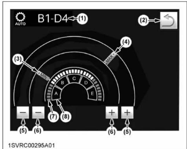
(1) Selected traveling speed gear shift
(2) Previous screen resume switch
(3) Low-speed slider
(4) High-speed slider
(5) High-speed setting switch
(6) Low-speed setting switch
(7) Main gear shift section
(8) Range gear shift section
9.2 Setting the traveling speed gear in the field mode
- Touch the field mode setting switch, and the "field mode" traveling speed gear setting screen shows up.

(1) Field mode setting switch
- Referring to the traveling speed chart, determine maximum and minimum main gear shifts that are best suited for the job in question.
-
Setting the maximum main gear shift: Using the high-speed setting switch, preset the desired traveling speed (the high-speed slider moves to the set position).
-
Setting the minimum main gear shift :
Using the low-speed setting switch, preset the desired traveling speed. (the low-speed slider moves to the set position). - The automatic gear shift is carried on within the displayed main gear shifts.
- Touch the previous screen resume switch, and the setting is completed and the previous screen reappears.

flowchart
graph TD
    A["1-4 AUTO"] --> B["(1)"]
    B --> C["6"]
    C --> D["5"]
    D --> E["4"]
    E --> F["3"]
    F --> G["2"]
    G --> H["1"]
    H --> I["(7)"]
    C --> J["(3)"]
    J --> K["+"]
    K --> L["(4)"]
    L --> M["+"]
    M --> N["(2)"]
    N --> O["←"]
    O --> P["(5)"]
    P --> Q["MAX"]
    Q --> R["(6)"]
    R --> S["←"]
    S --> T["(3)"]
    T --> U["-"]
    U --> V["(4)"]
    V --> W["←"]
    W --> X["(6)"]
1SVRC00296A01
(1) Selected traveling speed gear shift
(2) Previous screen resume switch
(3) Low-speed setting switch
(4) High-speed setting switch
(5) High-speed slider
(6) Low-speed slider
(7) Main gear shift range
9.3 Setting the auto shift sensitivity

(1) Auto shift sensitivity control
When operating in the auto shift mode
With the auto shift sensitivity control, the engine rpm for automatic gear shift up/down can be preset. Make readjustments according to the job in question for eco-friendly operation.
| Operating Auto shift sensitivity control Remarks | ||
| Eco-friendly operation with traveling speed priority | • Retract the graph leftward with the “Mi-nus (-)” switch. | Suited for light-duty work. |
| Operation with PTO shaft speed priority | • Extend the graph rightward with the “Plus (+)” switch. | Suited for heavy-duty work such as harvest-ing. |
When operating in the manual operation of the road mode
Suppose that the sensitivity level has been preset with the auto shift sensitivity control. If the ez-command center is used for gear shift over the range gear shift (from A to E) in such a case, the selected main gear shift works in a different way.
| Operating Auto shift sensitivity control Remarks | ||
| Light-duty | Retract the graph leftward with the “Mi-nus (-)” switch. | Shifted to the rev-up/slow-down levels by skipping the traveling speed range. |
| Heavy-duty | Extend the graph rightward with the “Plus (+)” switch. | Rev-up or slowed down close to the current traveling speed. |
9.4 Setting the engine rev-limit
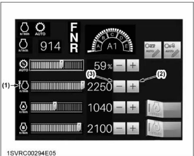
(1) Engine rev-limiter control graph
(2) "Plus (+)" switch
(3) "Minus (-)" switch
- Touch the target top engine rpm point on the engine rev-limiter control graph, and the slider will move to the touched point.
- With the "Plus (+)" or "Minus (-)" switch, finely adjust the rev-limit.
- When the point is set at MAX, the rev-limiter control is cancelled.
9.5 Setting the engine rpm memory
- Touch the target engine rpm point on the engine rpm memory control graph, and the slider will move to the touched point.
- With the "Plus (+)" or "Minus (-)" switch, finely adjust the rpm memory setting.
Every time the switch is pressed, the speed varies in 10-rpm increments or decrements.
- The engine rpm memory control (B) can also be preset in the same procedure.
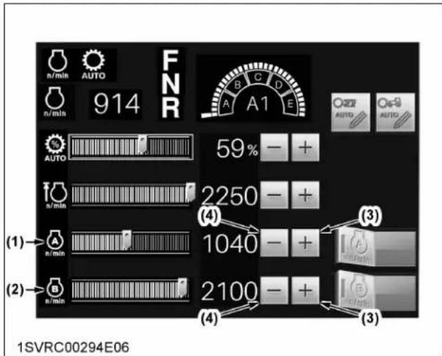
(1) Engine RPM memory (A) control
(2) Engine RPM memory (B) control
(3) Plus (+) switch
(4) Minus (-) switch
10. Setting the engine and CVT (Premium KVT model only)
Various settings of the continuously variable transmission (CVT) can be made and checked, as follows:
- Modifying the CVT sensitivity setting on page 86
- Modifying the CVT response setting on page 86
- Modifying the CVT low-range maximum speed setting on page 87
• Cruise control speed setting on page 87
In addition, the engine rev-limit and engine rpm memory settings may be pre-programmed, as follows:
- Setting the engine rev-limit on page 87
- Setting the engine rpm memory on page 87
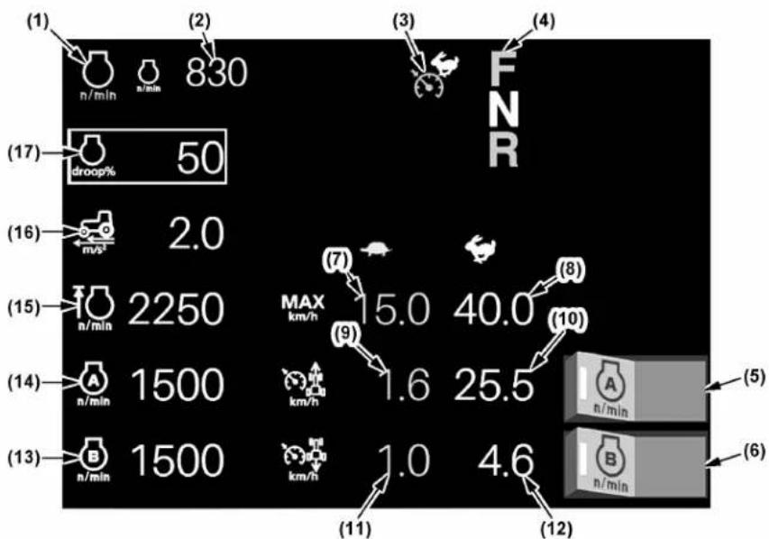
other
| Item | Efficiency (n/min) | FNR | | :--- | :--- | :--- | | (1) | 830 | | | (2) | 830 | | | (3) | 830 | | | (4) | 830 | | | (5) | 830 | | | (6) | 830 | | | (7) | 830 | | | (8) | 830 | | | (9) | 830 | | | (10) | 830 | | | (11) | 830 | | | (12) | 830 | | | (13) | 830 | | | (14) | 830 | | | (15) | 830 | | | (16) | 830 | | | (17) | 830 | | | droop% | 50 | | | n/s² | 2.0 | | | n/min | 2250 | MAX km/h | | n/min | 1500 | km/h | | n/min | 1500 | km/h | | n/min | 1500 | km/h | | A: n/min B: n/min MAX: km/h A: n/min B: n/min1SVRC00305A01
(1) Engine rpm memory (A/B) indicator
(2) Engine rpm
(3) Mode shift (Hi/Lo) indicator
(4) Shuttle lever indicator
(5) Engine rpm memory (A) switch
(6) Engine rpm memory (B) switch
(7) CVT low-range maximum speed
(8) CVT high-range maximum speed
(9) Cruise control low-range set speed (forward)
(10) Cruise control high-range set speed (forward)
(11) Cruise control low-range set speed (reverse)
(12) Cruise control high-range set speed (reverse)
(13) Engine rpm memory (B) control
(14) Engine rpm memory (A) control
(15) Engine rev-limiter control
(16) CVT response control
(17) CVT sensitivity control
10.1 Modifying the CVT sensitivity setting
- Touch the CVT sensitivity control and the setting screen shows up.

1SVRC00305B01
(1) CVT sensitivity control
2. Slide the CVT sensitivity control graph farther to the right (increasing the value) to decrease the CVT sensitivity. Readjust this level according to the type of work.
3. Press the previous screen resume switch and the setting is saved and the previous screen reappears.
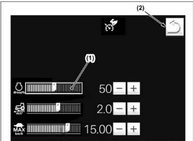
1SVRC00306A04
(1) CVT sensitivity control graph
(2) Previous screen resume switch
NOTE :
- Details regarding the CVT sensitivity settings can be found in a different section. (See Setting the continuously variable transmission (CVT) sensitivity on page 160.)
10.2 Modifying the CVT response setting
- Touch the CVT response control and the setting screen shows up.

1SVRC00305B02
(1) CVT response control
- Slide the CVT response setting control graph farther to the right (increasing the value) to increase response speed, allowing quick start and slowdown. Ideally, set the response level to low for towing heavy-duty implements and operating on slopes.
- Press the previous screen resume switch and the setting is saved and the previous screen reappears.

1SVRC00306A05
(1) CVT response control graph
(2) Previous screen resume switch
10.3 Modifying the CVT low-range maximum speed setting
- Touch the CVT low-range maximum speed control and the setting screen shows up.

(1) CVT low-range maximum speed control
-
Slide the CVT low-range maximum setting control graph farther to the right (increasing value) to increase the traveling speed available in the low-speed range. The traveling speed in the low-speed range may be preset up to 20 km/h (12.4 mph). This setting cannot be modified for the high-speed range.
-
Press the previous screen resume switch and the setting is saved and the previous screen reappears.

(1) CVT low-range maximum speed control graph
(2) Previous screen resume switch
10.4 Cruise control speed setting
Details regarding how to modify the cruise control speed settings can be found in a different section. (See Cruise control on page 161.)
10.5 Setting the engine rev-limit
- Touch the engine rev-limiter control, and the setting screen shows up.

(1) Engine rev-limiter control
-
Slide the engine rev-limit control graph to the right (increasing the value) to increase the engine rev-limit.
-
When the rpm is set at maximum, the rev-limiter control is canceled.
-
Press the previous screen resume switch, and the setting is saved and the previous screen reappears.

(1) Engine rev-limiter control graph
(2) Previous screen resume switch
10.6 Setting the engine rpm memory
-
Touch the target engine rpm point on the engine rpm memory control graph, and the slider will move to the touched point.
-
With the "Plus (+)" or "Minus (-)" switch, finely adjust the rpm memory setting.
Every time the switch is pressed, the speed varies in 10-rpm increments or decrements.
- The engine rpm memory control (B) can also be preset with the same procedure.

(1) Previous screen resume switch
(2) Engine rpm memory (B) control graph
(3) Engine rpm memory (A) control graph
(4) Plus (+) switch
(5) Minus (-) switch
(6) Engine rpm memory (A) switch
(7) Engine rpm memory (B) switch
(8) Engine rpm memory (A/B) indicator
11. Setting the headland management system
This chapter describes how to record, save, load, delete or modify the headland management system program, as follows:
• Preparations for recording the program on page 88
- Recording the program through actual tractor operation on page 89
• Pre-program lead time and pre-program travel distance on page 89
- Saving the program on page 90
- Loading the program on page 91
- Deleting the program on page 92
- Modifying the program (lead time) on page 92
- Modifying the program (switching) on page 93
• Headland management system program list on page 95
In addition, refer to the following section for, details regarding the handling procedure of the headland management system:
• HEADLAND MANAGEMENT SYSTEM on page 167
11.1 Preparations for recording the program
The program consists of 2 different types of operation, Field in and Field out, as listed in the following table.
Up to 20 programs can be saved and can be overwritten any number of times.
Before recording this program, read the details regarding the headland management system program list to confirm programmable actions.
(See Headland management system program list on page 95.)
- Touch the right half of the headland management system lock/unlock switch to unlock the program. A touch on the left half gets the program locked.
When the program is unlocked, the headland management system lock indicator goes off.
- Using the program select switch, choose the program code I. Every time the select switch is touched, the program code alternates among I, II, I', and III in that order.
The program code display indicator lights up interlocked with the program select switch.
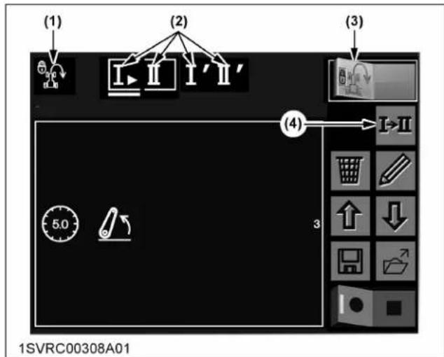
(1) Headland management system lock indicator
(2) Program code display indicator
(3) Headland management system lock/unlock switch
(4) Program select switch
Recordable program
| Type of work | Program select switch | Program Indicator |
| A | Code: I | Field out |
| Code: Field in | IndicatorIIlights up and the • circle lights up when recording. | |
| B | Code: I Field out | IndicatorIlights up and the • circle lights up when recording. |
| Code: II Field in | IndicatorIIlights up and the • circle lights up when recording. |
11.2 Recording the program through actual tractor operation
-
Make sure the headland management system lock indicator (5) is off.
-
Using the program select switch (2), be sure that the program code I (field out) is selected.
- Touch the left half of the automatic record switch (3), and the indicator (4) of this switch lights up to show that the program is ready to be recorded. Carry out actual work in accordance with the field-out operation procedure to record in the program.
- In the monitor's LCD screen, the subcategory icons (7) get displayed one by one according to the program recording order. If the tractor stops and the procedure is still used, the interrupt duration is recorded as lead time (8). If the tractor travels and the procedure is continued, the distance (9) is recorded.
- With the field-out operating procedure completed, touch the right half of the record switch (3) to end the recording procedure. Now the field-out operating procedure has been recorded.
- Next, using the program select switch (2), choose the program code II (field in).
- Record the field-in operating procedure. Now the recording for both the program codes I and II is completed. But the program has not been saved yet. Please do "save" as described in a different section.
(See Saving the program on page 90.)

(1) Headland management system lock/unlock switch
(6) Program codes I indicator
(2) Program select switch
(7) Subcategory icon
(3) Record switch
(8) Pre-program lead time
(4) Indicator
(9) Pre-program travel distance
(5) Headland management system lock indicator
11.3 Pre-program lead time and pre-program travel distance
The per-program lead time and per-program travel distance refer to the standby time and travel distance
from the moment a program is executed to the moment the next program gets started.
Field-out program example

flowchart
graph TD
    A["Field out button ON"] --> B["Main category Differential lock"]
    B --> C["Subcategory Differential lock OFF"]
    C --> D["Main category PTO"]
    D --> E["Subcategory Rear PTO OFF"]
    E --> F["Time or distance from the moment the differential lock OFF program has ended to the moment the rear PTO program gets started."]
11.4 Saving the program
- Make sure the headland management system lock indicator (1) is off.
- Using the program select switch (2), choose the program code to save.
The program code display indicator (3) lights up interlocked with the select switch (2). - Touch the program title display area (4) to display the input keypad.

(1) Headland management system lock indicator
(2) Program select switch
(3) Program code display indicator
(4) Program title display area
(2) Program select switch
(3) Program code display indicator
(4) Program title display area
- Entering the program title.
a. After entering the program title, touch the confirm switch (2).
![(1) I II I' II' Plow 1 2 3 4 5 6 7 8 9 0 - = qw er ty u i o p [ ] as d f g h j k l ; * z x c v b n m , . / # Insert Ω Delete (2) (3) 1SVRC00312A01](/content/2026/05/824941/images/fd9c841e67e096618cbec65c6aeb236af9da5971387d420d5176f33d72baa7e9.jpg)
(1) Input keypad
(2) Confirm switch
(3) Cancel switch
- Touch the program save switch (1).

(1) Program save switch
- Now the following screen appears.
a. Use the scroll switch (2) to select the blank slot (1) to save the program.
b. Then touch the confirm switch (3).

(1) Slot
(2) Scroll switch
(3) Confirm switch
NOTE :
- Up to 20 programs can be saved.
-
Selecting a loaded slot will overwrite the data.
-
The "Save sequence. Are you sure?" message appears.
-
If the confirm switch (1) is touched, the program will be saved.
- If the cancel switch (2) is touched, the program saving will be cancelled.

(1) Confirm switch
(2) Cancel switch
11.5 Loading the program
- Make sure the headland management system lock indicator (1) is off.
- Using the program select switch (2), choose the program code to load the program. The program code display indicator (3) lights up interlocked with the select switch (2).
- Touch the program load switch (4).
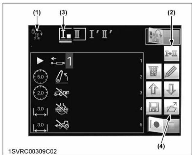
(1) Headland management system lock indicator
(2) Program select switch
(3) Program code display indicator
(4) Program load switch
- Now the following screen appears.
a. Use the scroll switch (2) to select the slot (1) to load the program.
b. Then touch the confirm switch (3).

(1) Slot
(2) Scroll switch
(3) Confirm switch
(4) Cancel switch
-
The "Load sequence. Are you sure?" message appears.
-
If the confirm switch (1) is touched, the program will be loaded to the selected program code.
- If the cancel switch (2) is touched, the program loading will be cancelled.

(1) Confirm switch
(2) Cancel switch
11.6 Deleting the program
- Make sure the headland management system lock indicator (8) is off.
-
Using the program select switch (2), choose the program code to delete.
-
To delete the entire program, touch the delete switch (3). The deleting can also be done by turning on the record switch (7) first and then immediately turning it off.
- To delete part of the program, use the scroll switch (5 or 6) to select the subcategory icon (10) to delete. Then touch the delete switch (3).

(1) Headland management system lock/unlock switch
(2) Program select switch
(3) Delete switch
(4) Edit switch
(5) Scroll switch (UP)
(6) Scroll switch (DOWN)
(7) Record switch
(8) Headland management system lock indicator
(9) Program code indicator
(10) Subcategory icon
11.7 Modifying the program (lead time)
This section describes an example of modifying the lead time for the PTO shaft to stop from the current 2-second entry to a 5-second entry.
- Make sure the headland management system lock indicator (7) is off.
-
Using the program select switch (2), choose the program code to modify.
-
Using the scroll switch (5 or 6) to select the PTO-related subcategory icon (9) to modify. Then touch the edit switch (4). The following editing screen appears.

(1) Headland management system lock/unlock switch
(2) Program select switch
(3) Delete switch
(4) Edit switch
(5) Scroll switch (UP)
(6) Scroll switch (DOWN)
(7) Headland management system lock indicator
(8) Program code indicator
(9) PTO-related subcategory icon
(10) Current lead time (2 seconds)
-
On the editing screen, the PTO-related main category icon (1) and subcategory icon (2), selected in the previous step 3, are automatically displayed.
-
Using the appearing numeric keypad, enter a new lead time (5 seconds in this example) and save the entry.
NOTE :
- To change the lead time to the pre-program distance, touch the distance and time select switch (5). The lead time icon (7) changes to the distance icon.
The steps hereafter are the same as for the lead time setting.
- Touch the confirm switch (3).
The "Change settings. Are you sure?" message appears.
If the confirm switch (1) is touched, the program will be modified and the previous screen will show up again.

(1) PTO-related main category icon
(2) Subcategory icon
(3) Confirm switch
(4) Cancel switch
(5) Distance and time select switch
(6) Delete switch
(7) Lead time icon (timer)

(1) Confirm switch
(2) Cancel switch
11.8 Modifying the program (switching)
This section describes an example of switching between the PTO program and differential lock program
- Make sure the headland management system lock indicator (7) is off.
-
Using the program select switch (2), choose the program code to modify.
-
Using the scroll switch (5 or 6) to select the PTO-related subcategory icon (9) to modify. Then touch the edit switch (4).
The following editing screen appears.
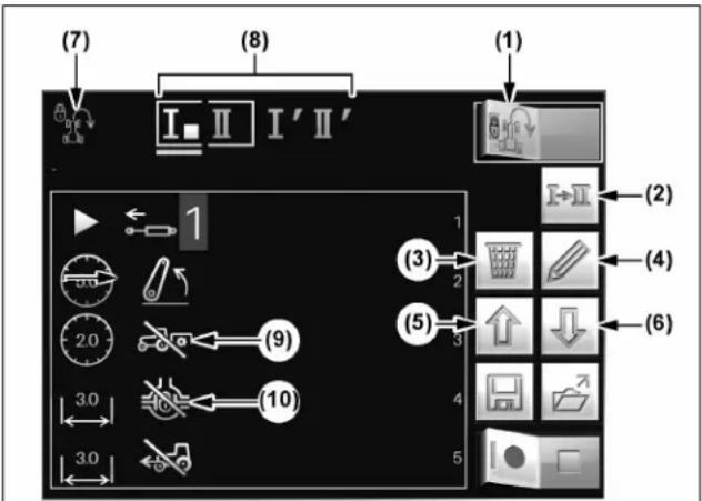
1SVRC00309B03
(1) Headland management system lock/unlock switch
(2) Program select switch
(3) Delete switch
(4) Edit switch
(5) Scroll switch (UP)
(6) Scroll switch (DOWN)
(7) Headland management system lock indicator
(8) Program code indicator
(9) PTO-related subcategory icon
(10) Differential lock icon
- On the editing screen, the PTO-related main category icon (1) and subcategory icon (5), selected in the previous step 3, are automatically displayed.
- Using the main category scroll switch (2), select the differential lock icon.
The subcategory icon (5) also changes itself to the differential lock icon.
- Using the subcategory scroll switch (6), select the differential lock "OFF" icon.
- Make sure the pre-program distance icon (7) is on. Then touch this icon.
If the lead time icon stays on, change it to the preprogram distance icon with the distance and time select switch (8).
- Using the appearing numeric keypad, enter a new distance, 3.0 m in this example, and save the entry.
- Touch the confirm switch (3).
The “Change settings. Are you sure?” message appears.
If the confirm switch (1) is touched, the program will be modified and the previous screen will show up again.
- Go back to step 3. Using the scroll switch (5 or 6) to select the differential lock subcategory icon (10) first and then touch the edit switch (4).
- The editing screen shows up. Now change the differential lock program to the PTO program.
Editing screen

flowchart
graph TD
    A["Step 1"] --> B["Action Icon"]
    C["Step 2"] --> D["Play Icon"]
    E["Step 3"] --> F["Checkmark"]
    G["Step 4"] --> H["Screen Icon"]
    I["Step 5"] --> J["Arrow to Start"]
    K["Step 6"] --> L["Arrow to End"]
    M["Step 7"] --> N["Arrow to End"]
    O["Step 8"] --> P["Arrow to End"]
    Q["#3 2.0"] --> R["Arrow to Start"]
    S["#3"] --> T["✓"]
    U["#4"] --> V["X"]
1SVRC00311A01
(1) PTO-related main category icon
(2) Main category scroll switch
(3) Confirm switch
(4) Cancel switch
(5) Subcategory icon
(6) Subcategory scroll switch
(7) Pre-program distance icon
(8) Distance and time select switch

(1) Confirm switch
(2) Cancel switch
11.9 Headland management system program list
| Main category Subcategory Remarks or detailed settings | |||
| 3-point hitch | Blocked Set rear hitch to I  | ||
| Work |  | Move rear hitch to work position(1)→ (2)→(3)→1SVRC00283A01(1) Rear hitch lowering speed adjustment(2) Draft sensitivity adjustment(3) Wheel slip ratio adjustment(4) Auto draft mode ON/OFF(5) Wheel slip control ON/OFF (2)→(3)→1SVRC00283A01(1) Rear hitch lowering speed adjustment(2) Draft sensitivity adjustment(3) Wheel slip ratio adjustment(4) Auto draft mode ON/OFF(5) Wheel slip control ON/OFF | |
| Float |  | Set rear hitch to float position.(1)→ 1SVRC00283B01(1) Rear hitch lowering speed adjustment 1SVRC00283B01(1) Rear hitch lowering speed adjustment | |
| Transport |  | Move rear hitch to transport position.(1) (2)1SVRC00284A01(1) Rear hitch upper limit adjustment(2) Rear hitch bottom limit adjustment(3) Ride control ON/OFF (2)1SVRC00284A01(1) Rear hitch upper limit adjustment(2) Rear hitch bottom limit adjustment(3) Ride control ON/OFF | |
Differential lock | Differential lock OFF |  | Switch differential lock off. |
| Differential lock ON |  | Switch differential lock on. | |
| Auto differential lock OFF |  | Switch auto differential lock off. | |
(Continued)
| Main category Subcategory Remarks or detailed settings | |||
Differential lock | Auto differential lock ON |  | Switch auto differential lock on. |
| 4WD← | 4WD OFF Switch 4WD off  | ||
4WD ON Switch 4WD on.  | |||
| Auto 4WD OFF |  | Switch auto 4WD off. | |
Auto 4WD ON Switch auto  | |||
PTO | PTO OFF Switch rear PTO  | ||
PTO ON Switch rear PTO  | |||
Auto PTO OFF Switch rea  TO off TO off | |||
| Auto PTO ON |  | Switch rear auto PTO on.(1)  1SVRC00266C01(1) Height setting when the rear hitch is raised for the PTO to turn off.(2) Height setting when the rear hitch is lowered for the PTO to turn on. 1SVRC00266C01(1) Height setting when the rear hitch is raised for the PTO to turn off.(2) Height setting when the rear hitch is lowered for the PTO to turn on. | |
Hand throttle mode | Hand throttle mode ON |  | Set engine speed to recorded hand throttle speed. 1SVRC00285A01(1) Time setting for reaching a preset engine rpm.(2) Setting of target engine rpm. 1SVRC00285A01(1) Time setting for reaching a preset engine rpm.(2) Setting of target engine rpm. |
| Engine rpm memory | Engine rpm memory OFF |  | Switch engine rpm memory off. |
(Continued)
| Main category Subcategory Remarks or detailed settings | |||
| n/min | Engine rpm memory (A) ON |  | Set engine speed to memory speed A.(1)— 1SVRC00267A01(1) Engine rpm setting to the memory (A) 1SVRC00267A01(1) Engine rpm setting to the memory (A) |
| Engine rpm memory (B) ON |  | Set engine speed to memory speed B.(1)— 1SVRC00267B01(1) Engine rpm setting to the memory (B) 1SVRC00267B01(1) Engine rpm setting to the memory (B) | |
| Power shift (Premium model) | Power shift gear change | [TZY2] | Change gear. 1SVRC00320A01(1) Power shift ratio adjustment 1SVRC00320A01(1) Power shift ratio adjustment |
| Road mode |  | Switch transmission mode to road mode.(1)—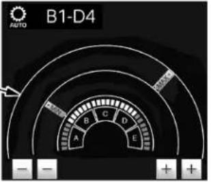 1SVRC00295B01(1) Road mode gear range adjustment 1SVRC00295B01(1) Road mode gear range adjustment | |
| Field mode |  | Switch transmission mode to field mode.(1)— 1SVRC00296B01(1) Field mode gear range adjustment 1SVRC00296B01(1) Field mode gear range adjustment | |
| Manual mode | [YWBD] | Switch operation mode to manual mode. | |
(Continued)
| Main category Subcategory Remarks or detailed settings | |||
CVT (Premium KVT model) | Cruise control OFF |  | Switch cruise control off. |
| Cruise control ON |  | Switch cruise control on. | |
| High speed range |  | Set mode shift to high speed range.(1)– (2)–1SVRC00271C01(1) CVT sensitivity setting (2) CVT response setting (2)–1SVRC00271C01(1) CVT sensitivity setting (2) CVT response setting | |
| Low speed range |  | Set mode shift to low speed range.(1)– (2)–(3)–1SVRC00271B01(1) CVT sensitivity setting(2) CVT response setting(3) Maximum traveling speed (2)–(3)–1SVRC00271B01(1) CVT sensitivity setting(2) CVT response setting(3) Maximum traveling speed | |
| Target travel speed |  | Set travel speed.(1)–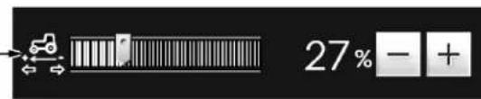 1SVRC00286A01(1) Setting of target travel speed 1SVRC00286A01(1) Setting of target travel speed | |
Remote control valve | Blocked (neutral) | The  | Valve is block. |
(Continued)
| Main category Subcategory Remarks or detailed settings | |||
Remote control valve | Extend |  | The 1st segment valve is extend.(1)- 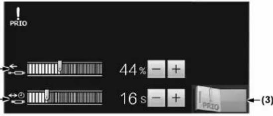 (2)-1SVRC00264C01(1) Flow rate (extend)(2) Flow timer(3) Priority flow status (2)-1SVRC00264C01(1) Flow rate (extend)(2) Flow timer(3) Priority flow status |
| Retract |  | The 1st segment valve is retract.(1)-  (2)-1SVRC00264D01(1) Flow rate (retract)(2) Flow timer(3) Priority flow status (2)-1SVRC00264D01(1) Flow rate (retract)(2) Flow timer(3) Priority flow status | |
| Float |  | The 1st segment valve is floating.(1)-  1SVRC00290A01(1) Flow timer 1SVRC00290A01(1) Flow timer | |
Front PTO | Front PTO OFF Switch front PTO off. | ||
Front PTO ON Switch front  | |||
12. Operating conditions
The tractor is equipped with one set of screens which automatically record information arbitrarily set from among some 18 types of operation information such as fuel consumption, time worked, work efficiency and so on, and one screen for information display only.
12.1 Calling up the data screen and preparation

(1) Operating conditions indicator
(2) Data record status indicator
(3) Screen number
(4) Free text box
(5) Working range of implement
(6) Recorded data
(7) Screen scroll switch
(8) Reset switch
(9) Edit switch
(10) Record start switch and stop switch
(11) Record conditions switch
K-monitor

K-monitor Pro
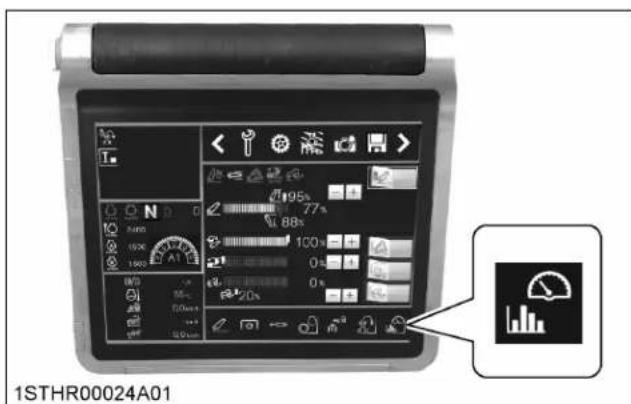
- Select the screen to be used for recording with the scroll switch (7).
The recording screen has 11 pages available (screens 1 to 11). Screen 0 is for information display only. - Touch the reset switch (8) to delete the recorded data from the screen.
- Enter field names and so on into the free text box (4) as necessary.
- Touch the free text box and use the displayed ten-key pad for input.
- Touch the working range of implement icon (5) to enter the working range of the implement, using the displayed ten-key pad.
If the working range of the implement is not correctly entered, accurate data will not be recorded. - Touch the edit switch (9) to switch to the edit screen.
12.2 Selecting and registering recorded data items
- Touch the edit switch to switch to the edit screen.

(1) Edit switch
- Touch the scroll switch icon at upper left to select the icon you want to register as recorded data.
- Touch the scroll switch icon second from upper left to select the icon you want to register.
- Touch the return to the previous screen switch, and the setting is completed and the previous screen reappears.
- Touch the factory setting button to return all icons on the displayed screen to the default display.
Edit screen

(1) Scroll switch
(2) Return to the previous screen
(3) Factory setting switch
12.3 Recordable data items
Register data items upon confirmation with the following chart.
| Icon Meaning Unit Remark | |||
 | Fuel consumption per hour | L/h (gal/h) | Not resettable |
 | Fuel consumption per work area | L/ha (gal/a) | Not resettable |
 | Work area covered per hour | ha/h (a/h) | Not resettable |
 | Engine coolant temperature | °C (°F) | Not resettable |
 | Travel speed | km/h (mph) | Not resettable |
 | Travel speed with GPS | km/h (mph) | Not resettable |
 | Travel speed with radar | km/h (mph) | Not resettable |
 | Pneumatic trailer brake pressure | bar (psi) | Not resettable |
 | System voltage v | Not resettable | |
 | Total operating hours — | Not resettable | |
 | Trip-operating hours | — | Resettable |
 | Trip-travel distance | km (ml) | Resettable |
 | Trip-fuel consumption | L (gal) | Resettable |
 Av. Av. | Trip-fuel consumption per hour | L/h (gal/h) | Resettable |
 | Trip-area fuel consumption | L/ha (gal/a) | Resettable |
 | Trip-area | ha (a) | Resettable |
(Continued)
| Icon Meaning Unit Remark | |||
 | Trip-work area covered per hour | ha/h (a/h) | Resettable |
 | Trip-idle time — | Resettable (engine running, tractor not moving, PTO off) | |
12.4 Setting the operating conditions and beginning recording
The operating conditions for which you want to record data can be set with the 5 switches at bottom right of the screen, and once set can be confirmed with indicators (8) through (12).
Simultaneous setting of multiple switches for operating conditions is also possible, but when setting for two conditions or more, data will be recorded when at least one condition has been met.
After setting, touch the record start switch (1) to begin recording, and the record stop switch (2) to end recording.

1STHR00121C01
(1) Record start switch
(2) Record stop switch
(3) Lift arm switch
(4) Remote control valve switch
(5) Front PTO switch
(6) Rear PTO switch
(7) Progress switch
(8) Lift arm indicator
(9) Remote control valve indicator
(10) Front PTO indicator
(11) Rear PTO indicator
(12) Front wheel drive (4WD) indicator
Lift arm
Touch the switch to switch the indicator among "Lift arm raise", "Lift arm lower" and "OFF".
- When you select "Lift arm raise", data will be counted only when the lift arm is raised.
- When you select "Lift arm lower", data will be counted only when the lift arm is lowered.
Remote control valve
Touch the switch to switch the indicator among "Remote control valve" 1 through 6 and OFF (unlit), in that order.
- When you select "Remote control valve 1", data will be counted only when valve 1 is operating.
Front PTO
Touch the switch to switch between the "ON" (lit) and "OFF" (unlit) indicators.
- When you select "Front PTO ON", data will be counted only when the front PTO is rotating.
Rear PTO
Touch the switch to switch between the "ON" (lit) and "OFF" (unlit) indicators.
- When you select "Rear PTO ON", data will be counted only when the rear PTO is rotating.
Progress
Touch the progress switch to switch between the "ON" (lit) and "OFF" (unlit) indicators.
- When you select "Progress", data will be counted only when the tractor is in progress.
12.5 Record status indicators
Record status indicators use the following colors for identification.
- Amber indicator lit: data is being recorded (counted)
- Green indicator lit: data recording interrupted
- Indicators off: data recording stopped
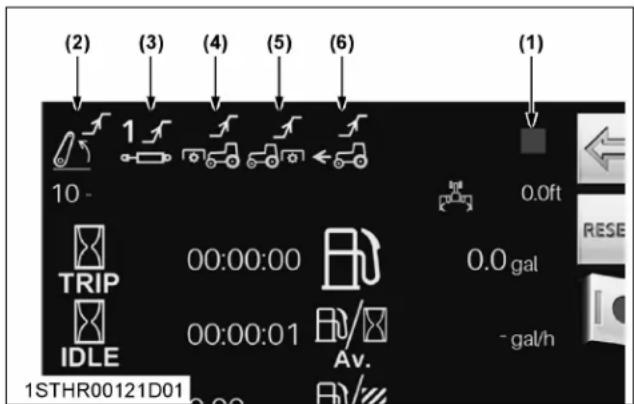
(1) Counting status indicator
(2) Lift arm indicator
(3) Remote control valve indicator
(4) Front PTO indicator
(5) Rear PTO indicator
(6) Progress indicator
K-MONITOR SUB-MENU (PREMIUM AND PREMIUM KVT MODELS ONLY)
This chapter covers the handling and operation of the "sub-menu".
Details regarding the handling and operation of the main menu can be found in a different section.
(See K-MONITOR MAIN MENU (PREMIUM AND PREMIUM KVT MODELS ONLY) on page 61.)
1. Live view camera
Installing a camera at an arbitrary position on the tractor or implement allows consistent checking on the work status from the operator's seat through the K-monitor.
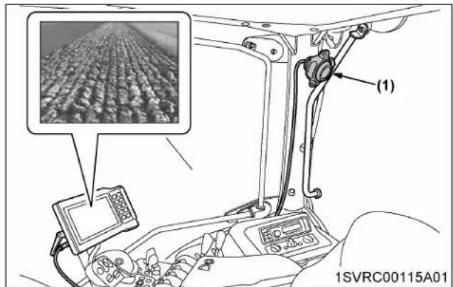
(1) View camera
2. Calculator
Make use of the calculator as necessary.

3. Initial setting
Details regarding the settings can be found in a different section.
(See System basic settings on page 69.)

(1) Gear icon
4. Data import and export
Digital-format data output is possible when using this mode, meaning that data import to a computer, and so on, is also easy.
This is highly convenient, since the reimportability of the exported data makes re-input of, for instance, details of the PTO and remote control valves unnecessary.
4.1 Exporting procedure
- After setting the USB memory stick in the K-monitor, touch the floppy mark on the display.

(1) Floppy mark
- Touch the export switch on the display to show 3 types of exportable data.
Check off the items you want to export by touching them.

flowchart
graph TD
    A["Device 1"] --> B["Device 2"]
    C["Device 2"] --> D["Device 1"]
    style A fill:#f9f,stroke:#333
    style C fill:#f9f,stroke:#333
    style B fill:#ccf,stroke:#333
    style D fill:#ccf,stroke:#333
(1) Export switch
(2) Import switch
- Touch the export switch to export to the USB memory stick.
- Touch the return switch to go back the previous screen.

(3) Export switch
(4) Return to the previous screen switch
4.2 Importing procedure
- After setting the USB memory stick in the K-monitor, touch the floppy mark in the display and then the import switch.
- Use the scroll switch to select data to import from the USB memory stick data at the top of the screen.
- Touch the import switch to copy the data. Further, note that when importing, the data within the K-monitor will be overwritten by the USB memory stick data selected in the previous step. However, the top limit setting value of the lift arm top limit cannot be imported.

(1) USB memory stick data
(2) Scroll switch
(3) Import switch
(4) Return to the previous screen switch
5. Screenshot
The screen data information set on each screen can be exported as graphic data (jpg format).
For example, if you export the details on the PTO or remote control valves set by implement as screenshots, resetting is simple.
Exporting procedure
- Display onscreen the information of which you want screenshots.
- Set the USB memory stick.
- Touch the camera icon at the top of the screen to copy the data to the USB memory stick.

(1) Camera icon
6. Failure messages
- Touch the wrench icon displayed in the sub-menu to check the information on current failures.

(1) Wrench icon

(1) Message scroll switches
PRE-OPERATION CHECK
DAILY CHECK
To prevent trouble from occurring, it is important to know the condition of the tractor. Check it before starting.

WARNING
To avoid personal injury or death:
- Be sure to check and service the tractor on a level surface with the engine shut off, the parking brake "ON" and the implement lowered to the ground.
Check item
- Walk around inspection
- Check engine oil level
- Check transmission oil level
- Check coolant level
- Check water separator
- Clean grill, radiator and cooler
- Check DPF/SCR muffler
- Check brake pedal
- Check parking brake lever
- Check pneumatic brake pressure (if equipped)
- Check indicators, gauges and meter
- Check lights
- Check seat belt
- Check movable parts
• Supply DEF/AdBlue ® - Check antifrost heater for oil separator (if equipped)
- Refuel
(See DAILY CHECK on page 238.) - Care of safety labels
(See SAFETY LABELS on page 18.)
SERVICE INSPECT INDICATOR
By monitoring the LCD unit on the instrument panel, the 10 maintenance items communicating with the tractor's hour meter can be kept under accurate control.
(See Checking the items reaching the maintenance interval on page 106.)
When engine oil, the most significant of all these, reaches its replacement time, the service inspect indicator will automatically appear on the LCD.

1STHR00055A01
(1) Service inspect indicator (wrench mark)
After replacing the oil, the indicator will disappear when you perform reset, but will appear when again reaching the relevant time.
Confirm the other maintenance items with the procedure below before operation as well. For this reason, act quickly when replacement and maintenance times are reached.
1. Checking the items reaching the maintenance interval
-
Press the [SET UP/00] switch on the instrument panel, and the setting mode screen appears.
-
With the [Select] switch, choose the "service inspect indicator". Then press the [ENT] switch.

flowchart
graph TD
    A["Select"] --> B["SETUP /00"]
    B --> C["ENT"]
    C --> D["ESC"]
    style A fill:#f9f,stroke:#333
    style B fill:#ccf,stroke:#333
    style C fill:#cfc,stroke:#333
    style D fill:#fcc,stroke:#333
    note1["1"] --> A
    note2["2"] --> B
    note3["3"] --> C
(1) [SET UP/00] switch
(2) [Select] switch
(3) [ENT] switch

(1) Setting mode screen
(2) Service inspect indicator
- The 10 maintenance items are displayed on the LCD unit.
The hours shown at the far right of each item indicate the duration of use after the immediately previous maintenance.

(1) Engine oil filter
(2) Fuel filter
(3) Hydraulic suction oil filter (3-point hitch)
(4) Transmission filter
(5) Transmission fluid
(6) Rear axle case oil
(7) Front axle case oil
(8) Wheel bolt torque
(9) Engine oil separator element
(10) Engine oil
Every time the [Select] switch is pressed, the circle (●) moves down and the next items appear one by one.
Highlighted hours mean that the inspection interval or replacement interval has been reached. Immediately inspect the relevant part or replace it with a new one.
2. Resetting the maintenance hour
When an inspection or replacement has been made, reset the hours of the maintenance item.
- Using the [Select] switch, move the circle (●) to the relevant maintenance item.

flowchart
graph TD
    A["Start"] --> B["Select"]
    B --> C["SET UP /00"]
    C --> D["ENT"]
    D --> E["ESC"]
    style A fill:#f9f,stroke:#333
    style B fill:#ccf,stroke:#333
    style C fill:#cfc,stroke:#333
    style D fill:#fcc,stroke:#333
    style E fill:#ffc,stroke:#333
(1) [SET UP/00] switch
(2) [Select] switch
(3) [ENT] switch
- Press the [ENT] switch, and the reset screen shown below appears. Using the [Select] switch, choose [YES]. Then press the [ENT] switch, and the displayed hours will be back to zero.

To avoid personal injury or death:
- Read and understand the safe operation section.
- Understand the safety labels located on the tractor.
- To avoid the danger of exhaust fume poisoning, do not operate the engine in a closed building without proper ventilation.
- Never start the engine while standing on ground. Start engine only from the operator's seat.
- Make it a rule to set all shift levers to the "NEUTRAL" positions and to place PTO clutch control switch in "OFF" position before starting the engine.
- When the engine is started, the machine height may change unexpectedly. Before starting the tractor, make sure the area near the machine is clear of all persons and objects (Front suspension type).
Details regarding safe operation can be found in a different section
(See SAFE OPERATION on page 11.)
IMPORTANT :
- Do not use starting fluid or ether.
- To protect the battery and the starter, make sure that the starter is not continuously turned for more than 10 seconds.
EXHAUST AFTERTREATMENT DEVICES

WARNING
To avoid personal injury or death:
- During diesel particulate filter (DPF) regenerating operations, exhaust gases and exhaust filter components reach temperatures hot enough to burn people or ignite or melt common materials.
- Keep tractor away from people, animals or structures which may be susceptible to harm or damage from hot exhaust gases.
- During regeneration, white exhaust gases may be visible. Do not allow regeneration in an unventilated garage or confined area.
- During regeneration, do not leave the tractor.
1. Dual exhaust aftertreatment devices
Particulate matter (PM) and black smoke contained in exhaust gases are trapped and removed by the diesel particulate filter (DPF) muffler.
The SCR system then decomposes residual nitrogen oxides (NOx) into harmless nitrogen (N2) and water (H2O) for purification.
This dual exhaust gas purifying device provides for clean exhaust gas at low fuel consumption.
DIESEL PARTICULATE FILTER (DPF) MUFFLER
This tractor is equipped with an engine with a diesel particulate filter (DPF) muffler which serves to reduce hydrocarbons, carbon monoxide and other toxic gases, all of which are contained in diesel engine emissions, to harmless carbon dioxide and water. The DPF also traps particulate matter (PM).
Please handle exhaust aftertreatment devices correctly and in an environmentally responsible manner.

(1) Diesel Particulate Filter (DPF)
1. Handling points
When a specific amount of particulate matter (PM) has accumulated in the DPF muffler, it is necessary to refresh the DPF muffler by burning the PM inside it.
This burning off work is called "Regeneration".
To extend operating time to reach this regeneration, and to avoid DPF muffler trouble, make sure to observe the following handling matters.
Fuel
Be sure to use ultra-low sulfur fuel (S15).
IMPORTANT :
- Use of diesel fuel other than ultra-low sulfur fuel may adversely affect the engine and DPF performance.
Use of fuels other than ultra-low sulfur fuel (S15) may not meet regulations for your region.
Engine oil
Use DPF-compatible oil (CJ-4) for the engine.
IMPORTANT :
- If any engine oil other than CJ-4 is used, the DPF may become clogged earlier than expected and the fuel economy may drop.
Prohibition of unnecessary idling operation
Generally, the lower the engine speed, the lower the exhaust gas temperature is, so the PM contained in exhaust gas will not be burned, and begins to accumulate. Therefore, do not idle unnecessarily.
Regeneration
When there is “Regeneration” instruction sign by lamp or buzzer, immediately perform the required procedure for regeneration.
IMPORTANT :
- Interrupting the regeneration cycle or continuing operation while ignoring the warning signs may cause DPF and engine damage.
2. DPF regeneration process
DPF regeneration process can be performed by choosing "Auto regeneration" or "Regeneration inhibit" mode according to your job conditions.
For jobs not affected by hot gases emitted during regeneration, "Auto regeneration" is advisable.
Auto regeneration mode
When starting the engine (switch operation is unnecessary), the “Auto regeneration” mode is automatically activated.
With the auto regeneration mode on, when a specific amount of PM has accumulated, and the regeneration conditions are satisfied, the DPF will be automatically regenerated whether the tractor is in motion or parked.
(See Tips on diesel particulate filter (DPF) regeneration on page 116.)
In this way, work efficiency is improved. For more details, read the “Auto regeneration” section of this manual.
(See Operating procedure for auto regeneration mode on page 111.)
Regeneration inhibit mode
After starting the engine, if the "DPF inhibit switch" is pressed to turn on the switch lamp, the "Regeneration inhibit" mode will be activated.
With "Regeneration inhibit" mode on, the PM which has accumulated inside the DPF will not be burned, unless the operator performs the regeneration work manually.
The “Regeneration inhibit” mode is effective for work in poorly ventilated workspaces.
For more details, read the regeneration prohibition section of this manual.
(See Operating procedure for regeneration inhibit mode on page 113.)
NOTE :
- If the engine is stopped once, the "Auto regeneration" mode will be activated.
3. Operating procedure for auto regeneration mode

(1) Parked regeneration switch
(2) DPF inhibit switch
(3) Regeneration indicator
(4) Parked regeneration indicator
(5) Engine RPM increase indicator
(6) Engine warning indicator
Regeneration operating procedure
1. Start the engine.
Make sure that the DPF inhibit switch lamp

Switch lamp "OFF": Auto regeneration mode activated.
Switch lamp "ON": Regeneration inhibit mode activated.
NOTE :
- When the engine is started, the "Auto regeneration" mode is automatically activated.
- "Regeneration inhibit" mode is activated when the DPF inhibit switch is pushed after the engine is started.
2. When the regeneration indicator

starts flashing:
A specific amount of PM has built up in the DPF.
Continue to operate the tractor, and the regeneration process will begin automatically; make sure the working place is in a safe area as DPF and exhaust temperature will rise.
3. When the engine rpm increase indicator

starts flashing:
Keep on working and increase the engine rpm until the indicator turns "OFF".
NOTE :
- Even if the auto regeneration mode is selected, DPF regeneration may not begin because system requirements have not been satisfied.
- The engine rpm increase indicator is used as a guide to satisfy the regeneration conditions. If the engine load is too heavy, the engine rpm increase indicator may continue to flash, even though regeneration system conditions are satisfied and regeneration may begin automatically.
(See Tips on diesel particulate filter (DPF) regeneration on page 116.)
3.1 PM warning level and required procedures
During auto regeneration mode when the PM level has built up in the DPF, the regeneration cycle will begin automatically.
If the regeneration cycle is interrupted or the regeneration conditions are not satisfied, the buzzer starts sounding and the indicator display changes in response to the PM level in order to prompt the operator to perform the required procedure listed in the following table.
IMPORTANT :
- Once the regeneration level has been reached, immediately perform the required procedure for regeneration.
Interrupting the regeneration cycle or continuing operation while ignoring the warning signs may cause DPF and engine damage.
| Auto mode | ||
| DPF system status Required procedure | ||
| PM warning level: 1Buzzer: Not sounding |  The regeneration indicator starts flashing. A specific amount of PM has accumulated in the DPF muffler.Continue to work the tractor to raise the DPF temperature. The regeneration indicator starts flashing. A specific amount of PM has accumulated in the DPF muffler.Continue to work the tractor to raise the DPF temperature. | |
 The rpm increase indicator starts flashing. Continue the work and increase the engine rpm until the indicator turns “OFF”. The rpm increase indicator starts flashing. Continue the work and increase the engine rpm until the indicator turns “OFF”. | ||
 The regeneration indicator will stop flashing and remain “ON” constantly. The regeneration indicator will stop flashing and remain “ON” constantly. | The regeneration cycle begins and continues until cycle is complete then the indicator will turn “OFF”. | |
| PM warning level: 2-1Buzzer: Sounding every 5 seconds | If the regeneration cycle was interrupted or conditions are not satisfied for regeneration then DPF system is now in Level 2. | |
 The regeneration indicator starts flashing. Start the regeneration, referring to PM warning level: 1 above.Now the parked regeneration indicator starts flashing, and the parked regeneration can also be started. The regeneration indicator starts flashing. Start the regeneration, referring to PM warning level: 1 above.Now the parked regeneration indicator starts flashing, and the parked regeneration can also be started. | ||
| PM warning level: 2-2Buzzer: Sounding every 3 seconds |  The rpm increase indicator starts flashing. The rpm increase indicator starts flashing. | |
 The parked regeneration indicator starts flashing. The parked regeneration indicator starts flashing. | (See Operating procedure for parked regeneration on page 115.) | |
| PM warning level: 3Buzzer: Sounding every 1 second Engine output: 50% | If the regeneration fails in the warning level 2: | |
 The engine warning indicator starts flashing. Immediately discontinue working the tractor and begin the parked regeneration cycle process.(See Operating procedure for parked regeneration on page 115.) The engine warning indicator starts flashing. Immediately discontinue working the tractor and begin the parked regeneration cycle process.(See Operating procedure for parked regeneration on page 115.) | ||
 The parked regeneration indicator starts flashing. At this PM warning level, the auto regeneration mode does not function.If the tractor is operated further, the regeneration cycle will be disabled. The parked regeneration indicator starts flashing. At this PM warning level, the auto regeneration mode does not function.If the tractor is operated further, the regeneration cycle will be disabled. | ||
| PM warning level: 4Buzzer: Sounding every 1 second Engine output: 50% | If the parked regeneration is interrupted or the tractor is continuously operated in the warning level 3: | |
 The engine warning indicator remains constantly “ON”. The engine warning indicator remains constantly “ON”. | Immediately move the tractor to a safe place, park it there and turn the engine “OFF”. Contact your local KUBOTA Dealer.• At this level, do not continue to operate the tractor; otherwise, damage will result to the DPF and engine. | |
4. Operating procedure for regeneration inhibit mode

(1) Parked regeneration switch
(2) DPF INHIBIT switch
(3) Regeneration indicator
(4) Parked regeneration indicator
(5) Engine RPM increase indicator
(6) Engine warning indicator
Regeneration operating procedure
-
Start the engine.
-
Press the DPF inhibit switch, and the switch lamp illuminates.
Switch lamp "ON": Regeneration inhibit mode selected.
Switch lamp "OFF": Auto regeneration mode selected.
- When the parked regeneration indicator =3 P starts flashing:
A specific amount of PM has accumulated in the DPF muffler.
Move the tractor to a safe place and activate the DPF muffler.
(See Operating procedure for parked regeneration on page 115.)
4.1 PM warning level and required procedures
In the regeneration inhibit mode, the buzzer starts sounding and the indicator display changes in response to the PM level in order to prompt the operator to perform the required procedure listed in the following table.
IMPORTANT :
- Once the regeneration level has been reached, immediately perform the required procedure for regeneration. Interrupting the regeneration cycle or continuing operation while ignoring the warning signs may cause DPF and engine damage.
| Regeneration inhibit mode | |||
| DPF system status Required procedure | |||
| PM warning level: 1Buzzer: Not sounding |  | The regeneration indicator starts flashing. A speciific level of PM has built up in the DPF muffler.Continue with the operation as it is. | |
 | At PM warning levels range from 1 to 2-2, it is also possible to change DPF inhibit switch to auto regeneration mode, then perform the regeneration. | ||
| PM warning level: 2-1Buzzer: Sounding every 5 seconds |  | The regeneration indicator starts flashing. Move | the tractor to a safe area, then begin the parked regeneration cycle process.(See Operating procedure for parked regeneration on page 115.) |
| PM warning level: 2-2Buzzer: Sounding every 3 seconds |  | The parked regeneration indicator starts flashing. | |
| PM warning level: 3Buzzer: Sounding every 1 second Engine output: 50% | If the parked regeneration cycle is interrupted or the tractor is continuously operated in the PM warning level 2: | ||
 | The engine warning indicator starts flashing. Im | mediately stop working the tractor, move the tractor to a safe area, then begin the parked regeneration cycle process.(See Operating procedure for parked regeneration on page 115.)If the tractor is operated further and the operator ignores the warning signs, then regeneration will be disabled. | |
 | The parked regeneration indicator starts flashing. | ||
| PM warning level: 4Buzzer: Sounding every 1 second Engine output: 50% | If the regeneration cycle is interrupted or the tractor is continuously operated ignoring the warning signs, in the PM warning level 3: | ||
 | The engine warning indicator remains constantly “ON”. | Immediately move the tractor to a safe place, park it there and turn the engine “OFF”.Contact your local KUBOTA Dealer.• At this level, do not continue to operate the tractor; otherwise, damage may result to the DPF and engine. | |
5. Operating procedure for parked regeneration
-
Park the tractor in a safe area away from buildings, people, and animals.
-
Apply the parking brake.
-
Set the shuttle shift lever to the neutral position.
-
Turn "OFF" the PTO clutch control switch.
-
Return the engine rpm to the idle speed.
-
Lower the implement to the ground.
-
Press the DPF inhibit switch ☐, and the switch lamp turns "OFF".
-
When the regeneration conditions are satisfied (2 to 5 and 7 mentioned previously), the parked regeneration switch lamp starts flashing.
-
Press the parked regeneration switch to start the regeneration cycle. The switch lamp will stop flashing and remain "ON" constantly during the cycle.
-
The engine rpm will automatically rise, and the regeneration process will begin.
-
Both indicators ① stay "ON" while regenerating the DPF.
They turn "OFF" when the cycle is complete.
- After the lamp turns "OFF", normal tractor work may resume.
When driving in "Regeneration inhibit" mode, press the DPF inhibit switch to turn on the switch lamp.
NOTE :
- During the regeneration cycle, do not touch the above levers and switches (in steps 2, 3, 4), nor change the engine rpm other than for an emergency stop. Otherwise, the regeneration will be interrupted.
- Never leave the tractor when the parked regeneration process is activated.
- If the parked regeneration cycle is interrupted, the engine rpm is fixed at the idling level for about 30 seconds. For this period, keep the hand throttle lever and foot throttle pedal at the idle position. Do not move them. They will function again in 30 seconds.
6. Tips on diesel particulate filter (DPF) regeneration
• Operation
The higher in speed or load the engine operates, the higher the exhaust temperature rises. As a result, particulate matter (PM) inside the DPF is consumed and the regeneration process is required less frequently over time.
The lower in speed or load the engine operates, the lower the exhaust temperature. Accordingly, less particulate matter (PM) inside the DPF is consumed and more accumulation of PM will occur, which requires frequent regeneration. Therefore, avoid prolonged idling if possible.
- Necessary conditions for "Regeneration"
When the conditions below are all satisfied, regeneration will start. However, if even one condition is deviated from during the process, the regeneration will be interrupted.
- The engine coolant temperature.
– The DPF temperature.
- The engine speed is 1200 rpm or higher.
• Usually, it takes 15-20 minutes to complete the regeneration cycle.
Actual regeneration time may depend on ambient temperature, exhaust temperature and engine speed.
- It is recommended to do the regenerating while the engine is warm.
- Do not unnecessarily start and interrupt the regeneration process. Otherwise, a small amount of fuel becomes mixed with the engine oil, which degrades the oil quality.
- While the DPF is being regenerated, the engine air flow rate is automatically limited to keep up the exhaust temperature. Because of this, the engine may sound differently, but this is normal for this engine.
- Just after the regeneration has ended, the DPF muffler remains hot. It is advisable to keep the engine running for about 5 minutes to allow cooling of the exhaust components.
SELECTIVE CATALYTIC REDUCTION (SCR) MUFFLER
1. Outline of the SCR
The injector jets urea aqueous solution (DEF/AdBlue ® ) into the muffler, and the solution is hydrolyzed with the heat of exhaust gas to generate ammonia (NH 3 ).
The ammonia generated thus is mixed with exhaust gas by the SCR muffler. In this way, nitrogen oxides (NOx) contained in exhaust gases are reduced by ammonia and decomposed into nitrogen and water vapor.

natural_image
Technical line drawing of a mechanical assembly with a cylindrical component and wiring (no text or symbols)(1) SCR muffler
2. DEF/AdBlue®

CAUTION
To avoid personal injury:
- The urea aqueous solution (DEF/AdBlue ) is colorless, odorless and harmless. If the solution gets on your skin, immediately wash it away with water.
The DEF/AdBlue ® , used as reducing agent of SCR, is a 32.5% urea aqueous solution.
No qualification for handling the urea aqueous solution is needed. As well, the solution is not designated as a hazardous material.
The product is available at gas stations, truck stops and specialty shops. Be sure to use the genuine product only.
Do not use any poor-quality products, or the engine may have trouble and be damaged.
Generally speaking, the consumption of DEF/AdBlue® is about 5% of the fuel.

(1) DEF/AdBlue ® tank (blue cap)
NOTE :
- On the North American market, the high-grade NOx reducing agent called urea aqueous solution is sold in the name of diesel exhaust fluid (DEF). On the European and Japanese
markets, it is on sale under the trade name of AdBlue®.
3. Warning indication and countermeasures
Before starting the day's job, check the fluid level with the DEF/AdBlue® gauge on the instrument panel.
If the fluid runs short during operation, the warning indicator lights up. If you continue running the machine as it is, the engine output will be limited by 50% or so. If running is continued, the engine will be limited to idling. (See SCR system icon on inducement display on page 117.)
These limitations are stipulated in conformity with the emission controls of each country and territory.

(1) DEF/AdBlue ® gauge
(2) DEF/AdBlue ® warning indicator
(3) DEF/AdBlue ® system warning indicator
3.1 SCR system inducement display on the LCD

(1) SCR system icon
(2) Engine output level
(3) Time limit to next level or remaining DEF/AdBlue ®
(4) Performance monitor (error code)
3.2 SCR system icon on inducement display
 | Low-level icon of DEF/AdBlue® |  | Trouble icon of SCR system | |
 | Poor-quality icon of DEF/AdBlue® |  | Freeze icon of DEF/AdBlue® |
3.3 SCR system inducement display and measures
On the SCR system, the remaining amount and quality of DEF/AdBlue ® as well as machine troubles are monitored. If anything goes wrong during operation, the following warnings are issued. Follow the warning contents to take proper measures.
| Displays | Warning indicator | Status Measures | DPF parked re-generation |
 40% 40% |  | 1 | The amount of remaining DEF/AdBlue® has dropped below 40% of the maximum capacity.Refill the DEF/AdBlue® tank to reset the warning system.To maintain tractor performance, it is recommended to add DEF/AdBlue® to the specified level quickly.If operation is continued without refilling, the engine output will be limited. |
 |  | 2 | The amount of remaining DEF/AdBlue® has dropped below 5% of the maximum capacity.Refill the DEF/AdBlue® tank. *1The engine output is limited to 50% (limited engine output: “Lv.1”).If operation is continued without refilling, the engine output will be limited to idle status (limited engine output: “Lv.2”). |
 Lv.1 30min Lv.1 30min |  | 2 | The amount of remaining DEF/AdBlue® has dropped below 5% of the maximum capacity.Refill the DEF/AdBlue® tank. *1The engine output is limited to 50% (limited engine output: “Lv.1”).If operation is continued without refilling, after 30 minutes, the engine output will be limited to idle status (limited engine output: “Lv.2”). |
 |  | 3 | The amount of remaining DEF/AdBlue® has dropped below 5% of the maximum capacity.The engine output will remain limited.Refill the DEF/AdBlue® tank. *1The engine output is limited to idle status (limited engine output: “Lv.2”). |
 |  | 1 | Contains poor quality DEF/AdBlue® or other non-regulated solutions.After draining the tank, refill with DEF/AdBlue® to reset the warning system.If operation is continued without refilling the DEF/AdBlue® tank, after 195 minutes, the engine output will be limited to 50% (limited engine output: “Lv.1”). |
 |  | 2 | Contains poor quality DEF/AdBlue® or other non-regulated solutions.After draining the tank, refill with DEF/AdBlue®. *1The engine output is limited to 50% (limited engine output: “Lv.1”).If operation is continued without refilling the DEF/AdBlue® tank, after 45 minutes, the engine output will be limited to idle status (limited engine output: “Lv.2”). |
 |  | 3 | Contains poor quality DEF/AdBlue® or other non-regulated solutions.After draining the tank, refill with DEF/AdBlue®. *1The engine output is limited to idle status (limited engine output: “Lv.2”). |
*1 When DEF/AdBlue® has been added or a poor-quality solution replaced by a genuine product, the warning indicator and icons turn off. The engine output limitation will also be cleared.
| Displays | Warning Indicator | Status Measures | DPF parked regeneration |
 |  | 1 | The SCR system has experienced an abnormality.Verify the error code displayed on the performance monitor and contact your local KUBOTA Dealer.The engine output is unrestricted.After 195 minutes, the engine output will be limited to 50% (limited engine output: “Lv.1”). |
 |  | 1 | The SCR system has experienced an abnormality.Verify the error code displayed on the performance monitor and contact your local KUBOTA Dealer.The engine output is limited to 80%.After 120 minutes, the engine output will be limited to 50% (limited engine output: “Lv.1”). |
 |  | 2 | The SCR system has experienced an abnormality.Verify the error code displayed on the performance monitor and contact your local KUBOTA Dealer.The engine output is limited to 50% (limited engine output: “Lv.1”).After 45 minutes, the engine output will be limited to idle status (limited engine output: “Lv.2”). |
 |  | 3 | The SCR system has experienced an abnormality.Verify the error code displayed on the performance monitor and contact your local KUBOTA Dealer.The engine output is limited to idle status (limited engine output: “Lv.2”). |
 | --- --- | Due to low temperatures, the DEF/AdBlue® has frozen.Continue the warm-up operation and the DEF/AdBlue® will thaw. | |
 | --- --- | Due to low temperatures, the DEF/AdBlue® has frozen. The engine output is limited to 80%.Continue the warm-up operation and the DEF/AdBlue® will thaw. |
NOTE :
• The limited engine output level:
The text "Lv.1" and "Lv.2" displayed next to the icon represents the limited engine output level.
“Lv.1” (Level 1): Within 50% of max torque and 60% of engine speed.
“Lv.2” (Level 2): Within engine near idling speed.
- After an error has occurred, it may be necessary for the engine output to become limited to "Lv.2". Depending on trouble spots and contents, the indicator-prompted warnings and the engine output limits and timings may vary accordingly.
The SCR warning status (from 1 to 3) represents the severity order of the engine output limitation. If the SCR system experiences abnormalities, an error code will be displayed, and it may be necessary to limit the engine output to idle status ("Lv.2").
For example, when a “ENG P-204F (FMI 1, SPN 1761)” error code is displayed, the engine output changes from unrestricted to “Lv.2” limited.
- Points after taking measures.
After the engine has stopped and the DEF/AdBlue has drained, if the amount that was refilled is less than the pre-drain amount, the SCR system may experience a malfunction (the error code “P20F5 (FMI 15, SPN 4350)” is displayed).
When the error occurs, turn the key switch to "OFF", wait for the SCR system to complete the purge process (this may take several minutes) and then turn the key switch to "ON" again in order to clear the SCR system malfunction.
- When there is a shortage of DEF/AdBlue ® , when it has been refilled with a poor-quality product, or when there is an abnormality in the SCR system, the auto regeneration and parked regeneration of the DPF may not function.
-
The time displayed on the lower right of the icon represents the minimum time until the limitation begins.
• The 40 hours warning record. -
Basically, warning and/or inducement reduction cancel when the fault location is repaired.
- However, if it detects any fault within 40 hours of the restoration, it soon returns to the previous failure and the timer restarts counting down.
- The 40 hours warning record will be reset if any fault has not been detected over 40 hours from the repair.
If a fault is detected after the 40 hours warning record reset, then the new countdown will be stated.
4. Storing and handling DEF/AdBlue®
- Because DEF/AdBlue® is an urea aqueous solution, it begins to freeze at ambient temperatures below -11 °C (12 °F). In winter, handle it with sufficient care.
- DEF/AdBlue may be stored in the tractor's tank for up to 4 months. If the storage area's ambient temperature rises above 30 irc C (86 irc F), however, its storage life will be markedly reduced.
Storage method
- Store the solution in a well-sealed container.
- Place the container in a location not exposed to direct sunlight.
- Place the container in a well-ventilated spot.
- Keep the container in a spot without violent temperature changes.
- Keep the container away from any containers of gasoline and diesel fuel.
STARTING THE ENGINE
1. Setting the battery switch
- Before getting the engine started, set the battery switch to the "ON" position. With the switch at "OFF", the engine fails to start.
- When the battery switch is turned on, the indicator will be on.
- After the work has ended or before a temporary storage, set the battery switch to the "OFF" position.
- Before long-term storage, disconnect the battery cables from the battery terminals.

(1) Battery switch
(2) Indicator
(A) "OFF"
(B) "ON"
NOTE :
- By keeping the battery switch at "OFF", there will be a smaller risk of battery fire caused by wrong cabling.
- Even when the battery switch is "OFF", small current for the clock and other devices is constantly flowing.
- After turning the key switch to "OFF" and stopping the engine, the SCR system automatically begins to cool off the system and extract DEF/AdBlue® from the lines. Even if the battery switch is turned to "OFF" in order to accomplish this task, the power will be sustained for about 15 minutes to protect the SCR system components. The indicator for the battery switch will blink while energized and turn off when energization is completed.
- Remove the battery after the indicator is turned off.
2. Engine starting procedure
Preheating of the engine is automatic. Make sure the heater indicator goes out and then get the engine started.
- Set both the foot throttle and the hand throttle to the minimum speed position and start the engine.
- When getting the engine started, the main gear shift and shuttle gear shift are automatically locked at the "NEUTRAL" position. The PTO clutch control switch also turns itself off.
Before operating the machine, return these levers and switches once to "NEUTRAL (OFF)" and set them again as required.
- When the engine is stalled by the heavy load applied, please key off once and re-start the engine after 5 seconds or more.
- The lock/unlock status of the hydraulic lifting unit before stopping the machine has been put in memory. Get it locked or unlocked as required.
STARTING THE ENGINE IN COLD WEATHER
If the ambient temperature is below 0 °C (32°F) and the engine is very cold, perform the following procedure:
- Turn the key to "ON" position and hold it until the heater indicator turns off. Heater indicator comes on when the key is turned to "ON" position and engine coolant temperature is below 0 °C (32 °F), and goes off automatically when preheat is completed.
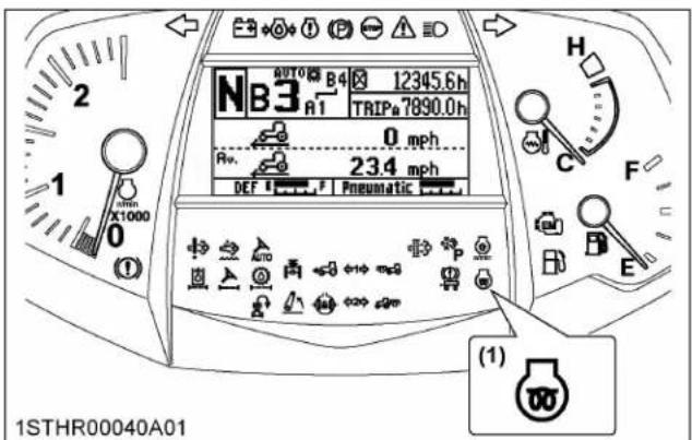
(1) Heater indicator
- Turn the key to the "ST ART" position and the engine should start.
- If the engine fails to start after 10 seconds, turn off the key for 30 seconds and then repeat steps 1 and 2.
To protect the battery and the starter, make sure that the starter is not continuously turned for more than 10 seconds.
1. Antifrost heater for oil separator (if equipped)
The heater element operates continuously when the key switch is in the "ON" or "START" position.
Due to high electrical draw, extended idle time or operations will drain the battery and stop the tractor.

natural_image
Mechanical assembly diagram showing interconnected pipes and components (no readable text or symbols)(1) Heater
2. Block heater (if equipped)
A block heater is available as an option from your dealer. It will assist you in starting your tractor when the ambient temperature is below -20 °C (-4 °F).
3. Engine low temperature regulation
In order to prevent engine damage due to rapid acceleration, if starting the engine when coolant temperature is approximately 0\ °C ( 32\ °F ) or below, the engine rpm will be kept at approximately 1000 for up to 5 minutes, and the operator will be informed by indicator and intermittent buzzer. The regulation time varies in response to the coolant temperature.
During regulation, perform warm-up operation without using the accelerator. After regulation, the engine rpm can be gradually increased. When regulation has been completely released, the indicator will go off and the buzzer will stop.

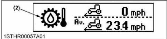
(1) Engine low temperature regulation indicator
(2) Transmission low temperature regulation indicator
NOTE : The indicator lighting condition will vary depending on the specification.
- For Standard, Deluxe, Premium models: - If the cooling water temperature is 0 °C (32 ℉) or below, the engine low temperature
regulation indicator will light up and the buzzer will sound.
• For Premium KVT models:
- If the cooling water temperature is 0ircC (32°F) or below and the transmission oil temperature is -7ircC (19°F) or more, the engine low temperature regulation indicator will light up and the buzzer will sound.
- If the cooling water temperature is 0ircC (32°F) or below and the transmission oil temperature is also -7ircC (19°F) or below, the engine low temperature regulation indicator and transmission low temperature regulation indicator will alternately light up and the buzzer will sound.
- If the transmission oil temperature is -7 °C (19 °F) or below when engine low temperature regulation has been released, the buzzer will stop but the transmission oil low temperature regulation indicator will remain lit.
4. DEF/AdBlue ® freeze warning
When operating in cold weather, the DEF/AdBlue® is automatically thawed while the engine is running.
However, in weather conditions of under -30 °C(-22 °F), the DEF/AdBlue® cannot be completely thawed and thus, an error/warning code [P208B] appears on the instrument panel's LCD screen.
If the error/warning code [P208B] appears on the screen, stop the engine and restart it after 10 seconds. After restarting the engine, the error/warning code [P208B] will disappear and the thawing of the DEF/AdBlue® will resume.
In case the error/warning code [P208B] remains on the screen even after restarting the engine several times, contact your local KUBOTA Dealer.
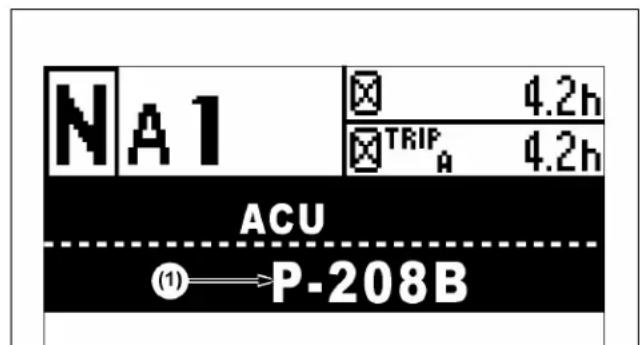
1STHR00063A01
(1) Error/warning code
STOPPING THE ENGINE
- After slowing the engine to idle, wait 3 to 5 minutes for turbo to slow down and then turn the key to "OFF".
- Remove the key.
NOTE :
- If removing the key does not stop the engine, consult your local Kubota Dealer.
- After turning the key switch to "OFF" and stopping the engine, the SCR system automatically begins to cool off the system and extract DEF/AdBlue® from the lines.
Operating sound may continue to be heard from the SCR system (for example, from the DEF/AdBlue ® tank or DEF/AdBlue ® pump) after stopping the engine, but this is the operating sound of the SCR system and not an abnormal sound.
WARMING UP THE ENGINE

WARNING
To avoid personal injury or death:
- Be sure to set the parking brake during warm-up.
- Be sure to set all shift levers to the "NEUTRAL" positions and to place the PTO lever in the "OFF" position during warm-up.
For 5 minutes after engine start-up, allow the engine to warm up without applying any load; this is to allow oil to reach every engine part. If load should be applied to the engine without this warm-up period, trouble such as seizure, breakage or premature wear may develop.
1. Warm-up and transmission fluid at low temperature range
Hydraulic oil serves as transmission fluid. In cold weather, the oil may be cold with increased viscosity.
This can cause delayed oil circulation or abnormally low hydraulic pressure for some time after engine start-up. This, in turn, can result in trouble in the hydraulic system.
To prevent the above, observe the following instructions:
Warm up the engine at about 50% of rated rpm according to the following table:
| Ambient temperature Warm-up time requirement | |
| Higher than 0 °C (32 °F) Approx. 5 minutes | |
| 0 to -10 °C (32 to 14 °F) 10 to 20 minutes | |
| -10 to -20 °C (14 to -4 °F) 20 to 30 minutes | |
| Below -20 °C (-4 °F) More than 30 minutes |
IMPORTANT :
- Do not operate the tractor under full load condition until it is sufficiently warmed up.
2. Transmission low temperature (premium KVT model only)
In order to prevent transmission damage due to poor lubrication and so on, when the transmission fluid temperature is approximately -7 °C (19 °F) or below, regulation will take place depending on the fluid temperature as in the following table. As well, the operator will be informed during regulation by indicator and message.
During regulation, perform warm-up operation without using the accelerator.
When the indicator goes off and the message disappears, gear shifting is available.
| Transmission fluid temperature | Regulation time | Regulation content |
| -7 °C to -15 °C (19 °F to 5 °F) | Approx. 3 min | No start (shuttle gear neutral)Engine rpm kept at approx. 1100 to 1400 |
| -16 °C to -20 °C (4 °F to -4 °F) | Approx. 5 min | |
| -21 °C to -30 °C (-5 °F to -22 °F) | Approx. 7 min |

1STHR00058A01
(1) Transmission low temperature regulation indicator
(2) Message (for example: [TCU FMI 18 SPN 524193])
NOTE :
- If the cooling water temperature is 0ircC (32°F) or below and the transmission oil temperature is
also -7 °C (19 °F) or below, the engine low temperature regulation indicator and transmission low temperature regulation indicator will alternately light up.
- If the cooling water temperature is 0 °C (32 F) or below when transmission low temperature regulation has been released, the engine low temperature regulation indicator will remain lit.
JUMP STARTING

WARNING
To avoid personal injury or death:
- Battery gases can explode. Keep cigarettes, sparks, and flames away from the battery.
- If the tractor battery is frozen, do not jump start engine.
- Do not connect the other end of the negative (-) jumper cable to the negative (-) terminal of the tractor battery.
- When taking out the dead battery, putting in the battery or fixing the battery, do not allow the positive (+) terminal of the battery to touch other parts.
When jump starting the engine, follow the instructions below to safely start the engine.
- Bring the helper vehicle with a battery of the same voltage as the disabled tractor within easy cable reach.
IMPORTANT :
• The vehicles must not touch.
- Engage the parking brakes of both vehicles and put the shift levers in neutral. Shut both engines off.
- Wear eye protection and rubber gloves.
- Attach the red clamp to the positive (red, (+) or positive) terminal of the dead battery and clamp the other end of the same cable to the positive (red, (+) or positive) terminal of the helper battery.
- Clamp the other cable to the negative (black, (-) or negative) terminal of the helper battery.
- Clamp the other end to the engine block or frame of the disabled tractor as far from the dead battery as possible.
-
Start the helper vehicle and let its engine run for a few moments. Start the disabled tractor.
-
Disconnect the jumper cables in the exact reverse order of attachment (steps 6, 5 and 4).
Connect cables in numerical order. Disconnect in reverse order after use.

(1) Dead battery
(2) Jumper cables
(3) Helper battery
IMPORTANT :
- This tractor has a 12 volt negative (-) ground starting system.
- Use only the same voltage for jump starting.
- Use of a higher voltage source on tractor's electrical system could result in severe damage to tractor's electrical system.
Use only matching voltage source when "Jump starting" a low or dead battery condition. - Do not operate the tractor with the battery cable disconnected from the battery.
- Do not operate the tractor without the battery mounted.
- Do not operate the tractor with the battery dead. Charge the battery fully before operating the tractor.
Otherwise, the tractor might malfunction.
ENGINE OPERATION
1. Key switch
The starter switch has 4 positions.

"OFF" (engine-stop)
"ACC" (electrical power-accessories)
“ON” (engine-run)
"START" (engine-start)
NOTE :
Regarding ACC:
- All the accessories can be used while the engine is stopped.
- Do not leave the key at "ACC" position. The battery will be quickly discharged. Turn it back to "OFF" after use.
2. Engine power boost
In any of the following conditions, the engine output is boosted for higher working efficiency. For work requiring no high output, on the other hand, the machine runs at standard output level with fuel economy in mind.
Trailer towing work
When the traveling speed rises above 20 km/h (12.4 mph), the engine output boosts itself. When it drops below 18 km/h (11.2 mph), the power boost turns itself off.
PTO operation
When the PTO clutch is engaged, the engine output boosts itself.
3. Rev-limiter control setting
When the rev-limiter control is used to restrict the maximum engine speed, the engine speed will not exceed the set speed even when the hand throttle or foot throttle is operated. This can prevent machine trouble caused by incorrect operation.
Setting the speed (Standard and Deluxe models)
The setting can be made both when the engine is running and when it is stopped.
- Set the speed by turning the dial to the left or right while watching the engine speed that is displayed on the LCD
- When the dial is turned all the way to the right, the restriction is canceled
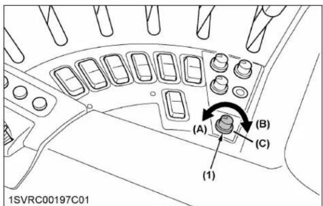
(1) Rev-limiter control dial (A) "LOW-SPEED SIDE"
(B) "HIGH-SPEED SIDE"
(C) "CANCELLED"

(1) Maximum engine speed
NOTE :
- When the engine rev-limit is preset with the LCD indicator on the instrument panel, the speed can be monitored with the following indicator.
Setting the speed (Premium and Premium KVT models)
Maximum engine speed can be preset on the K-monitor.
(See Setting the engine and CVT (Premium KVT model only) on page 85.)

(1) Engine rpm
(2) Engine rev-limit control
(3) Minus (-) switch
(4) Plus (+) switch
When the engine rev-limit is preset with the LCD indicator on the instrument panel, the speed can be monitored with the following indicator.
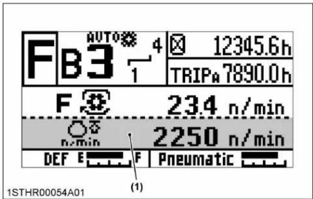
(1) Maximum engine speed
4. RPM dual memory setting
Two different engine speeds can each be set with a single touch by pressing the (A) or (B) rpm memory
buttons or switches. This can be used to eliminate troublesome acceleration operations.
Standard, Deluxe models

(1) Engine rpm memory button (A)
(2) Engine rpm memory button (B)
(3) Engine rpm memory adjustment button (up)
(4) Engine rpm memory adjustment button (down)
Premium, Premium KVT models
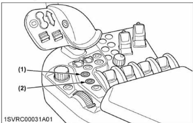
(1) Engine rpm memory button (A)
(2) Engine rpm memory button (B)

(1) Engine rpm memory (A/B) indicator
(2) Engine rpm memory switch (A)
(3) Engine rpm memory switch (B)
NOTE :
- To activate the set engine rpm memory (A) or (B), touch the left half of the engine rpm memory switch (2) or (3). Touch the right half of switch to deactivate.
Example of use
Consider an example in which an engine speed of 2000 rpm is set for the button (A) and a speed of 1000 rpm is set for the button (B).

| Work↓ |  |  |
| During work, simply press the button (A) to automatically set an engine speed of 2000 rpm. | ||
| Turning↓ |  |  |
| When turning, press the button (B) to lower the speed to 1000 rpm, allowing turning at low speed. | ||
| Work |  |  |
| After turning, press the button (A) again to resume a speed of 2000 rpm. | ||
- Keep the hand throttle above the minimum speed. At the minimum speed, a memory setup can not be performed.
- You can also depress the foot throttle to increase the engine speed above the set speed.
4.1 Setting the speeds (Standard and Deluxe models)
Setting 1 (with the engine running)
- First make sure that the indicators of the engine rpm memory buttons (A) and (B) are both off.
- Using the hand throttle, increase the engine rpm to the desired preset level.
- Hold down the engine rpm memory button (A), and the current rpm level is memorized in the engine rpm memory button (A) as memory rpm take the same procedure for the engine rpm memory button (B).
Setting 2
- Before making the engine rpm memory setting with the engine off, get the memory rpm levels (A) and (B) displayed in the LCD on the instrument panel and check the levels to readjust.
(See Basic information monitor and performance monitor on page 53.) - Make sure that the indicators of the engine rpm memory buttons (A) and (B) are both off. Then set the hand throttle above the minimum speed.
- Press the engine rpm memory button (A) (its indicator lights up).
- While checking the memory rpm displayed in the LCD, set a desired rpm with the engine rpm memory adjustment button (up) or (down). Every time the relevant button is touched, the speed changes in 10-rpm increments or decrements. Hold down the button, and the speed continuously changes.
Use the same procedure for the engine rpm memory button (B).

(1) Engine rpm memory button (A)
(2) Engine rpm memory button (B)
(3) Engine rpm memory adjustment button (up)
(4) Engine rpm memory adjustment button (down)
4.2 Setting the speeds (Premium and Premium KVT models)
Two different engine rpm levels can be present on the K-monitor screen.
Details regarding the engine transmission settings can be found in a different section.
(See Setting the engine rpm memory on page 84 and Setting the engine rpm memory on page 87.)
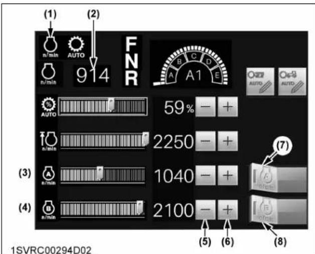
(1) Engine rpm memory (A/B) indicator
(2) Engine rpm
(3) Engine rpm memory (A) control
(4) Engine rpm memory (B) control
(5) Minus (-) switch
(6) Plus (+) switch
(7) Engine rpm memory (A) switch
(8) Engine rpm memory (B) switch
NOTE :
• The set speeds will be stored even after the engine is stopped.
4.3 Canceling the setting (all models)
Any of the following actions will cancel the rpm dual memory settings.
- For the switch (A) side, when the memory speed is engaged, press the switch (A) again to cancel.
For the switch (B) side, when the memory speed is engaged, press the switch (B) again to cancel. - When the memory speed is canceled, the speed will return to the speed that is determined by the hand throttle (foot throttle).
- Return the hand throttle to the lowest speed position.
- Turn the key switch to "OFF".
NOTE :
- If the memory rpm level has been preset beyond the engine rev-limiter setting, the engine rpm will not rise above the rev-limit. Take an example in which the engine rev-limiter is 1230 rpm and the memory speed is 2000 rpm. The engine speed will rise only up to 1230 rpm.
How a new tractor is handled and maintained determines the life of the tractor.
A new tractor just off the factory production line has been, of course, tested, but the various parts are not accustomed to each other, so care should be taken to operate the tractor for the first 50 hours at a slower speed and avoid excessive work or operation until the various parts become “broken-in”. The manner in which the tractor is handled during the “breaking-in” period greatly affects the life of your tractor.
Therefore, to obtain the maximum performance and the longest life of the tractor, it is very important to properly break-in your tractor. In handling a new tractor, the following precautions should be observed.
1. Do not operate the tractor at full speed for the first 50 hours
- Do not start quickly nor apply the brakes suddenly.
- In winter, operate the tractor after fully warming up the engine.
- Do not run the engine at speeds faster than necessary.
- On rough roads, slow down to suitable speeds. Do not operate the tractor at high speed.
The above precautions are not limited only to new tractors, but to all tractors. However, they should be especially observed in the case of new tractors.
2. Changing lubricating oil for new tractors
The lubricating oil is especially important in the case of a new tractor. The various parts are not “broken-in” and are not accustomed to each other. Small metal grit may develop during the operation of the tractor, and this may wear out or damage the parts. Therefore, care should be taken to change the lubricating oil a little earlier than would ordinarily be required.
For more details, read the maintenance section of this manual.
(See MAINTENANCE on page 230.)
BOARDING AND LEAVING THE TRACTOR
- Never try to get on or off a moving tractor or jump off the tractor to exit.
- Face the tractor when getting into or out of the tractor. Do not use the controls as handholds to prevent inadvertent machine movements.
- Always keep steps and floor clean to avoid slippery conditions.

natural_image
Silhouette of a person climbing stairs with barbells (no text or symbols)1NHNP00133A01
- The seat and suspension should be adjusted to ensure that the controls are comfortably at hand for the operator, ensuring that the operator maintains a good posture and minimizes risks from whole body vibration.
1. Operator's seat

WARNING
To avoid personal injury or death:
- Make adjustments to the seat only while the tractor is stopped.
- Make sure that the seat is completely secured after each adjustment.
- Do not allow any person other than the operator to ride on the tractor.
Standard, Deluxe model

(1) Travel adjust lever
(A) "UP"
(2) Weight and height adjust switch
(B) "DOWN"
(3) Fore and aft isolator
(C) "ON"
(4) Backrest tilt adjust lever
(D) "OFF"
(5) Seat cushion extension lever
(F) "SOFT"
(6) Swivel adjust lever
(7) Cushion tilt adjust lever
(8) Arm rest
(9) Arm rest adjustment
(10) Backrest extension
(11) Lumbar support adjust knob
(12) Firmness adjustment knob
Premium, Premium KVT model
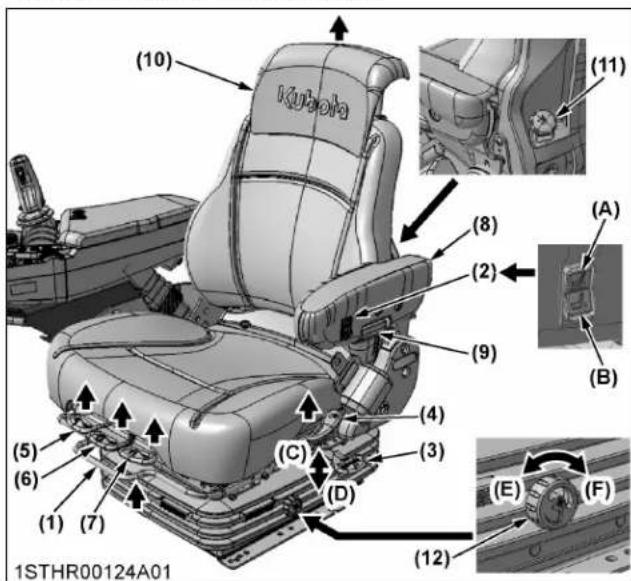
(1) Travel adjust lever
(A) "UP"
(2) Weight and height adjust
(B) "DOWN"
switch
(C) "ON"
(3) Fore and aft isolator
(D) "OFF"
(4) Backrest tilt adjust lever
(E) "FIRM"
(5) Seat cushion extension lever
(F) "SOFT"
(6) Swivel adjust lever
(7) Cushion tilt adjust lever
(8) Arm rest
(9) Arm rest adjustment
(10) Backrest extension
(11) Lumbar support adjust knob
(12) Firmness adjustment knob
Travel adjustment
Pull the travel adjust lever and slide the seat backward or forward, as required. The seat will lock in position when the lever is released.
Weight and height adjustment
Turn on the key switch. The seat should be adjusted for the operator's weight by holding down weight and height adjust switch (A) or (B) with the tractor in a stationary position and the operator sitting on the seat.
The seat can be adjusted in its adjustable range.
NOTE :
- If the seat is lowered below the adjustable range, it automatically comes up to the lower limit of the adjustable range just when the weight and height adjust switch is unoperated.
IMPORTANT :
- In order to avoid damage of the seat, do not operate the weight and height adjust switch for more than 1 minute.
Fore and aft isolator
Set the isolator in "ON" position so that shock impacts in the direction of travel can be better absorbed by the seat.
Firmness adjustment
The seat suspension can be adjusted as follows:
Turn the firmness adjustment knob to the (E) position for the firmer ride or (F) position for the softer ride.
Lumbar support adjustment
Turn the lumbar support adjust knob to the desired position.
Tilt adjustment
Pull the backrest tilt adjust lever and tilt the backrest to the desired position.
Backrest extension
Pull the backrest extension to the desired height.
Arm rest
Armrest may be set at upright position if desired.
Arm rest height adjustment
Turn the adjustment knob to the desired height of the armrests.
RH arm rest (Premium, Premium KVT models only)
The right arm rest height is adjustable. To reposition the arm rest height, unlock the lock handle and slide the arm rest upward or downward, and securely lock it by hand so that you can operate the levers and switches comfortably.
In this case, please attach the lock handle to the position of (2) when moving the armrest to higher limit, and position of (3) when moving the armrest to lower limit.

(1) RH arm rest
(A) "HIGH"
(2) Lock handle (High mount position)
(B) "LOW"
(3) Lock handle (Low mount position)
(C) "LOCK POSITION"
(D) "UNLOCK POSITION"
Swivel adjustment
Unlock the swivel adjust lever and rotate the seat right or left as desired.
NOTE :
Using the swivel seat:
- Swivel the seat to the right and left to position yourself comfortably for jobs in which you need to look rearwards.
- Turn the seat to the left to facilitate getting in and out of the tractor.
• The seat can swivel in both directions.
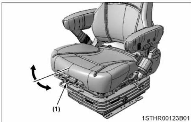
natural_image
3D mechanical assembly diagram of a car seat with labeled components and rotation arrow (no text or symbols beyond labels)(1) Swivel adjust lever
2. Operator presence control (OPC) system
The tractor is equipped with a system which stops the PTO and activates a warning buzzer.
This system functions according to the conditions below.
When the tractor is stopped:
- Even if the PTO clutch control switch is engaged, the PTO will not start if the operator is standing up from the operator's seat.
- If the key switch is at "ON" position (engine running or not) and the parking brake is not applied, standing up from the operator's seat will set off the warning buzzer.
- If shuttle is not "NEUTRAL" and the parking brake is applied, standing up from the operator's seat will set off the warning buzzer and shuttle changes to "NEUTRAL" (Premium KVT model only).
- If the tractor is not traveling with the PTO running, standing up from the operator's seat will stop the PTO and sound the warning buzzer for 1 second.
When the tractor is moving:
- Standing up from the operator's seat will set off the warning buzzer and the PTO will continue rotating.
3. Seat belt
WARNING
To avoid personal injury or death:
- Always use the seat belt when a ROPS or CAB is installed.
Adjust the seat belt for proper fit and connect the buckle. This seat belt is auto-locking retractable type.

(1) Seat belt
4. Instructional seat (if equipped)

(1) Instructional seat
(2) Seat belt
(3) Handrail
Intended use
The instructional seat is intended for training purposes.
A tractor instructor, a trainee or a servicing staffer is supposed to use this seat of CAB-equipped tractors on flat, safe grounds, where the potential for roll-over is practically zero. Do not drive the tractor along expressways and public ways.
Understanding the previously mentioned purposes, do not use this seat under any other conditions than specified.
The conditions which show as examples not to use this seat are as follows.
- Do not allow any other persons and animals than the instructor, the trainee or servicing staffer on this seat. Never allow children to sit down on this seat. Do not place anything on this seat for transport purpose.
- Use this seat only for training purpose, not for anything else.
- Never use this seat on any locations where the machine might turn over. Never operate the machine prone to turn over, either.
Slopes, rough terrains, high-speed running, sharp turns, towing, sudden starting, stopping and so on.
- Do not use this seat whenever the operator's view is affected by bad weather (such as rain and fog) or in the late afternoon.

WARNING
To avoid personal injury or death:
• Always wear your seat belt and stabilize your body by holding the handrail on the CAB frame.
- It is not intended to carry children nor any other person for any other purposes.
- The left-hand door must be closed at all time whenever the instructional seat is occupied and the tractor is in motion.
- Do not permit others to ride, except on the designated instructional seat.
- Use caution to avoid the risks of obstructing operator's view, falling from the machine and interfering with controls.
- Do not start and stop the tractor suddenly, nor take a sharp turn.
- Do not use the instructional seat if the seat belt or the door lock fails to function.
- Do not use the instructional seat for transport.
- When opening or closing the door while being seated in the instructional seat, move the door slowly. This is to prevent his or her hand(s) from getting caught by the door or his or her body to hit against the door.
4.1 Precautions in using the instructional seat
When getting on the tractor
- The operator is supposed to move the tractor onto a flat surface and to apply the parking brake for a complete stop.
- Before use, make sure the seat is securely fixed. And get on the tractor. In getting on the tractor, stabilize yourself by holding the specified handrail with attention not to get in contact with any control levers.
- Fasten the seat belt and close the door. Then get the door locked.
While the tractor is in motion
- The person on the instructional seat is supposed to get training with due care not to interfere with the operator's actions.
- While in training, be sure to keep the seat belt fastened. The person on the instructional seat is supposed to grip the handrail to prevent him or her from getting out of balance due to violent machine movements.
- Run the tractor at low speed.
When getting off the tractor
- The operator is supposed to move the tractor onto a flat surface and to apply the parking brake for a complete stop.
- The person on the instructional seat is supposed to open the door, unfasten the seat belt and get out of the tractor.
- Rewind the seat belt back into its case.
NOTE :
- The instructional seat can be used only when permitted by your local laws. Consult your local KUBOTA Dealer for further details.
5. Steering adjustment
CAUTION
To avoid personal injury:
- Do not adjust the steering wheel while the tractor is in motion.
Press down the steering wheel lock pedal, to release the lock so the steering wheel can be adjusted to the desired position.

(1) Lock Pedal (A) "UNLOCK"
(B) "LOCK"
6. Extendable mirror
- To alter the length, loosen the knob bolt and move the mirror to the required position, then tighten the knob bolt.
- To adjust mirror head, hold firmly, tilt horizontally and vertically as required.

(1) Knob bolt
7. 2-sided mirror (if equipped)
A 2-sided mirror which greatly enlarges the field of view on both sides of the tractor is provided as standard equipment.
Adjust the angle of the upper mirror to observe the rear of the tractor and the status of near implement.
The lower mirror is a wide angle type.
Adjust the lower mirroring order to have a wider view of the rear tires.
Adjustment Method
For both the upper and lower mirror, lightly press the portion highlighted by the arrow in any direction with a fingertip to adjust the angle.
Do not adjust the angle by pressing the 4 corners of the mirror.

(1) Wide angle mirror part
8. Heater for rear view mirror (if equipped)
The rear-view mirrors are equipped with a defogger function.
To activate defogger, press the heater mirror switch while the key switch is in the "ON" position.
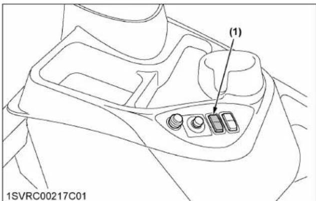
(1) Heater mirror switch
9. Remote control mirror (if equipped)

WARNING
To avoid personal injury or death:
- Adjustment while driving is extremely dangerous.
Stop the tractor before adjusting the mirrors.
The angle of the left and right rear view mirrors can be adjusted while sitting in the driver's seat.
For confirmation of implements and crops inside the field, rear view while driving on the road, and so on, angle adjustment can be done with a single touch as needed.
Adjustment Method
- Set the key switch to "ON" or "ACC" position
- Use the adjustment knob to adjust the mirror.
- Adjust the angle of the mirror by tilting the adjustment knob up, down, left or right.
- Return the adjustment knob to the center position after the adjustment is completed.


(1) Adjustment knob
(2) Upper right mirror adjustment position
(3) Upper left mirror adjustment position
(4) Lower right mirror adjustment position
(5) Lower left mirror adjustment position
IMPORTANT :
- Do not hold the mirror with your hand while adjusting.
LIGHT CONTROLS
1. Lights
Turn on the repeat headlight only when an implement using the front 3-point hitch obstructs the beam of the headlight.

(1) Headlight
(2) Repeat headlight (if equipped)
(3) Position light
(4) Turn signal and hazard light
(5) Work light (if equipped)

(1) Turn signal and hazard light
(2) Tail light
(3) Stop light
(4) Work light (if equipped)
1.1 Light switch (without repeat headlight type)
- Turn the key to the "ON" position.
- In accordance with the switch positions, the lights in the following table light up.
(1) Adjustment knob
(2) Upper right mirror adjustment position
(3) Upper left mirror adjustment position
(4) Lower right mirror adjustment position
(5) Lower left mirror adjustment position

(1) Switch (3 positions) (A) "PUSH"
| Switch position | |
| All lights off (a) position | |
| Position light on (b) position | |
| Headlight and position light on (c) position | position |
Headlight beam selection lever
The headlight switches between low and high beam each time you move the lever to the (B) position. When the headlight is on low beam, it will flash when the lever is moved to the (A) position.
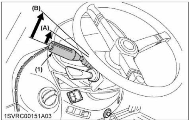
(1) Headlight beam selection lever
(A) "Flash" (on low beam)
(B) "Low or high beam switch"
NOTE :
- High beam indicator will be on when selection lever is in "HIGH BEAM" position.
- To prompt the operator to turn off the lights, the buzzer starts sounding if the key is turned to "OFF" position with lights on.
1.2 Light switch (with repeat headlight type)
- Turn the key to the "ON" position.
- In accordance with combinations of the switches 1 and 2, the lights in the following table light up.

(1) Switch 1 (3 positions) (2) Switch 2 (2 positions)
| Switch position | ||
| Switch 1 Switch 2 | ||
| All lights off | (a) position | — |
| Position light on | (b) position | — |
| Headlight and position light on | (c) position | (d) position |
| Repeat headlight and position light on | (c) position | (e) position |
Headlight beam selection lever
The headlight switches between low and high beam each time you move the lever to the (B) position. When the headlight is on low beam, it will flash when the lever is moved to the (A) position.

(1) Headlight beam selection lever
(A) "Flash" (on low beam)
(B) "Low or high beam switch"
NOTE :
- High beam indicator will be on when selection lever is in "HIGH BEAM" position.
- To prompt the operator to turn off the lights, the buzzer starts sounding if the key is turned to "OFF" position with lights on.
2. Turn signal switch and hazard light switch
Hazard light
- When the hazard light switch is pushed, the hazard lights flash, along with the LH and RH indicators on the instrument panel.
- Push the hazard light switch again to turn off the hazard lights.
Turn signal with hazard light
- To indicate a right turn with the hazard lights already flashing, turn the switch clockwise.
- To indicate a left turn with the hazard lights already flashing, turn the switch counterclockwise.
- When the left or right turn signal is activated in combination with the hazard lights, the indicated turning light will flash and the other will stay on.
Turn signal without hazard light
- To indicate a right turn without hazard lights, turn the switch clockwise.
- To indicate a left turn without hazard lights, turn the switch counterclockwise.
- When the left or right turn signal is activated without the hazard lights, the indicated turning light will flash and the other will stay on.
NOTE :
- The hazard light switch is operative when the key switch is in the "ON", "ACC" or "OFF" position.
- The turn signal light switch is only operative when the key switch is in the "ON" position.
- Be sure to return the turn signal switch to center position after turning.

(1) Hazard light switch
(2) Turn signal light switch
(3) Hazard and turn signal indicator
(A) "RIGHT TURN"
(B) "LEFT TURN"
Trailer indicator
When you operate the turn signal light switch with the trailer power connector connected, the trailer indicator in the instrumental panel also starts flashing along with the turn signal indicator.

(1) Hazard and turn signal indicator
(2) Trailer 1 indicator
(3) Trailer 2 indicator
2.1 Horn button
The horn will sound when the horn button is pushed.

(1) Horn button
(A) "PUSH"
3. Work light switch

WARNING
To avoid personal injury or death:
- Do not operate on roads with work lights on. Work lights may blind or confuse operators of oncoming vehicles.
Turn on the key switch and press each work light switch. The work light and the switch's indicator light up.
Press each work light switch again to turn off the light and indicator.

flowchart
graph TD
    A["1"] --> B["2"]
    B --> C["3"]
    C --> D["4"]
    D --> E["5"]
    E --> F["6"]
    F --> G["ESC"]
    H["Select"] --> I["SET UP /00"]
    J["ENT"] --> K["ESC"]
    style A fill:#f9f,stroke:#333
    style B fill:#f9f,stroke:#333
    style C fill:#f9f,stroke:#333
    style D fill:#f9f,stroke:#333
    style E fill:#f9f,stroke:#333
    style F fill:#f9f,stroke:#333
    style G fill:#f9f,stroke:#333
    style H fill:#f9f,stroke:#333
    style I fill:#f9f,stroke:#333
    style J fill:#f9f,stroke:#333
    style K fill:#f9f,stroke:#333
(1) Front work light switch (engine hood)
(2) Front work light switch (sides of the CAB)
(3) Front work light switch (roof of the CAB)
(4) Rear work light switch (roof of the CAB)
(5) Rear work light switch (rear of the CAB)
(6) Indicator

(1) Front work light (engine hood)
(2) Front work light (sides of the CAB)
(3) Front work light (roof of the CAB)

(1) Rear work light (roof of the CAB)
(2) Rear work light (rear of the CAB)
4. Beacon light switch
Turn on the key switch and press the beacon light switch. The beacon light and the switch's indicator light up.
Press the beacon light switch, and turn off the light and the indicator.

flowchart
graph TD
    A["Sensor 1"] --> B["Control Unit"]
    C["Sensor 2"] --> B
    B --> D["Select"]
    B --> E["SET UP"]
    B --> F["ENT"]
    B --> G["ESC"]
    style A fill:#f9f,stroke:#333
    style C fill:#f9f,stroke:#333
    style B fill:#ccf,stroke:#333
(1) Beacon light switch
(2) Indicator
BRAKE CONTROLS
This machine is equipped with the following types of brakes.
Handle appropriately, referencing this manual with your tractor and attached implement(s).
1. Foot brake
WARNING
To avoid personal injury or death:
- Be sure to interlock the right and left pedals. Applying only one rear wheel brake at high speeds could cause the tractor to swerve or roll-over.
- Be sure brake pedals have equal adjustment when using locked together. Incorrect or unequal brake pedal adjustment can cause the tractor to swerve or roll-over.
- Be aware of the enhanced braking characteristics of 4-wheel braking system. Appropriate care should be taken during hard braking and/or when pulling towed loads.
- Do not brake suddenly. An accident may occur as a result of a heavy towed load shifting forward or loss of control.
- To avoid skidding and less of steering control when driving on icy, wet, or loose surfaces, make sure the tractor is correctly ballasted, operated at reduced speed, operated with front-wheel drive engaged (if equipped).
- The braking characteristics are different between 2 and 4-wheel drive. Be aware of the difference and use carefully.
-
Engage 4-wheel drive for 4-wheel braking when traveling down a slope.
-
Before operating the tractor on the road, be sure to interlock the right and left pedals as illustrated below.
-
Use individual brakes to assist in making sharp turns at slow speeds (field operation only). Disengage the brake pedal lock and depress only one brake pedal.
- Be sure brake pedals have equal adjustment when being used locked together.

(1) Brake pedal lock (A) "LOCK"
(B) "RELEASE"
1.1 4WD braking system (4WD model)
4WD model tractor is equipped with 4WD braking system.

WARNING
To avoid the possibility of personal injury, death or property damage from machine runaway during testing, service or repair with the rear wheels off the ground, make sure:
- Battery is disconnected and engine is not started.
If it is necessary to run the engine, make sure: - Both front and rear wheels are off the ground and secured with stands before starting engine.
When both brake pedals are applied together, the front axle is engaged for 4-wheel braking regardless of the mode selected at the 4WD switch. The 4WD indicator light is not illuminated unless the front axle is engaged with the selector switch.
2. Parking brake
- Before getting off the tractor, pull the parking brake lever up to park. To release the parking brake, depress the brake pedal, push the release button and push the parking brake lever down.
- If you leave the operator's seat without applying the parking brake while the key switch is at "ON" position, the parking brake OPC indicator will turn on and the alarm buzzer will sound.
- Once the parking brake has been applied, the tractor sets itself in the 4-wheel drive mode. This
helps the 4 wheels to increase their gripping force on slopes.

(1) Parking brake lever (2) Release button

(1) Parking brake warning indicator (2) Parking brake OPC indicator
NOTE :
- When the key switch is turned off with no parking brake applied, the warning buzzer sounds for around 10 seconds.
- The parking brake warning indicator on the Easy Checker™ will go off when the parking brake is unlocked.
- If the tractor starts moving when the parking brake is engaged, the alarm buzzer sounds and the parking brake warning indicator blinks.
IMPORTANT :
- Do not attempt to put the tractor in motion before the parking brake warning indicator light turns off.
- If the tractor is operated with the parking brake set, the parking brake might be damaged.
2.1 When towing a dual-line trailer brake type trailer
When the parking brake is set to "ON", the brakes are applied to wheels on both the tractor and trailer sides, and the brake performance when parked improves. (See Trailer brake on page 140.)
3. Trailer brake
The trailer brakes are activated when using the tractor's brake pedals. It uses the pressure from the main hydraulic or air compressor circuit. The braking force while towing is proportional to the force applied on the tractor pedals.
It is most useful when towing very heavy loads, this device considerably increases braking efficiency and safety.
3.1 Confirmation
This machine is equipped with connectors for pneumatic and/or hydraulic trailer brakes.
When connecting the trailer, check the trailer side brake type carefully before correctly connecting the various hoses.
Connection errors will inhibit full brake performance, which is extremely dangerous.
Confirm the trailer side brake type with the following illustration.

(1) Pneumatic trailer brakes (2) Hydraulic trailer brake
3.2 Hydraulic trailer brake

natural_image
Technical line drawing of an automotive electrical panel with no visible text or symbols(1) Hydraulic control hose (large diameter, green cap)
Connect the hydraulic hose of the towed vehicle to the outlet (large diameter) of the tractor. If the hydraulic brake hose are not connected, the brake system may malfunction and accidents may occur. Carefully check the brake mechanism of the towed vehicle and connect the hoses correctly.
- The hydraulic control hose (large diameter, green cap) has the role of transmitting the signal from the foot brake pedal to activate the trailer brakes.
NOTE :
- Stop the engine and apply the parking brake before attaching and detaching the hydraulic hose.
IMPORTANT :
- Make sure to only connect and use a trailer with hydraulic trailer brake.
3.3 Pneumatic trailer brake
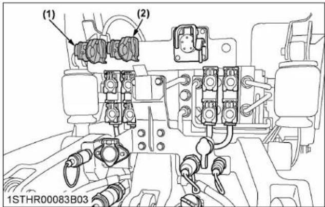
(1) Connector (A), yellow (dual-line brake) (2) Connector (B), red (dual-line brake)
Connect the air hoses securely to the connectors (A) and (B) of the tractor.
Air is constantly supplied to the trailer side air tank via the red connector hose.
Pneumatic pressure proportional to the force on the brake pedal is transmitted via the yellow connector
hose to the trailer side brake equipment, and activates the brakes according to the pressure.
When the parking brake is applied, the internal pressure in the red connector hose drops, activating the trailer brakes.
IMPORTANT :
- Make sure the air hose connections are clean. After using the air hoses, be sure to put their protective caps back in position.
- With the air hoses connected, step on the brake pedal several times with the engine off to make sure there is no air leak at the connections.
3.3.1 Inspecting the pneumatic pressure
The pneumatic trailer brake pressure can be checked with the "pneumatic pressure gauge" on the instrument panel. If the pressure drops below specified, the "trailer brake warning indicator" on the instrument panel lights up.

(1) Pneumatic pressure gauge
(2) Trailer brake warning indicator
3.4 Trailer brake warning indicator
If trouble should occur at the trailer brake system, the trailer brake warning indicator lights up.

(1) Trailer brake warning indicator
TRAVEL CONTROLS
1. Clutch pedal

WARNING
To avoid personal injury or death:
- Sudden release of the clutch may cause the tractor to lunge in an unexpected manner.
• Always use the clutch pedal to start the tractor.
The clutch is disengaged when the clutch pedal is fully pressed down.
There is no need to operate the clutch for shifting with the main gear shift, range gear shift and shuttle shift. But clutch operation is needed for creep gear shifting (if equipped).

(1) Clutch pedal
IMPORTANT :
To help prevent premature clutch wear:
• The clutch pedal must be quickly disengaged and be slowly engaged.
- Avoid operating the tractor with your foot resting on the clutch pedal.
- Select proper gear and engine speed depending on the type of job.
- If the warning buzzer sounds too often during usual job, the tractor may require reprogramming. Consult your local KUBOTA Dealer for this service.
NOTE :
- If the clutch is operated in a partially engaged conditions, the warning buzzer will sound (for 1 second) and a warning code will be displayed to protect the clutch.
Press the [ESC] button and the warning code will disappear.

(1) Warning code
(2) [ESC] button
2. Hand throttle
Pulling the throttle lever backward decreases engine speed, and pushing it forward increases engine speed.
NOTE :
- With the rev-limiter control on, the engine speed will not rev above the limiter-preset rpm even if the hand throttle is operated.
3. Foot throttle
Use the foot throttle when traveling on the road. Press down on it for higher speed. The foot throttle is interlocked with the hand throttle; when using the foot throttle, keep the hand throttle in low idling position.
NOTE :
- With the rev-limiter control on, the engine speed will not rev above the limiter-preset rpm even if the foot throttle is operated.
- Let's suppose that the "Automatic mode" is selected with the CVT type tractor. You can control both the speed and the engine power by how deeply you step on the foot throttle, as with an automatic transmission car.
(See Operation of the automatic mode on page 158.)
4. Shuttle lever
WARNING
To avoid personal injury or death:
- When attempting to shift the shuttle shift lever on a slope, be sure to completely stop the tractor.
- Slow down the engine speed before shifting the shuttle lever.
- Use the shuttle lever when the machine speed is below 20 km/h (12.4 mph).
NOTE :
- If the previous warnings are not followed, the clutch gets disengaged and the buzzer starts sounding. To get the clutch reengaged and clear the buzzer, take either of the following steps.
- Place the shuttle lever back to the original position.
- Decrease the machine speed lower than 20 km/h (12.4 mph) and use the shuttle lever.
Raise up and shift the shuttle shift lever forward to obtain forward speeds and shift it backward to obtain reverse speeds without using the clutch pedal.
Whether traveling or at a stop, push down the shuttle lever and it will return to the "NEUTRAL" position.
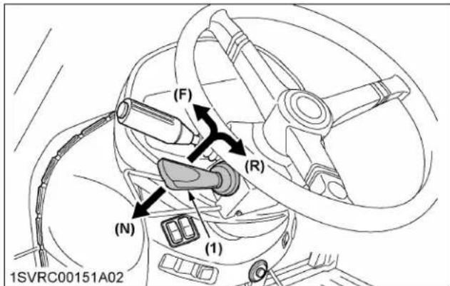
(1) Shuttle lever (F) "FORWARD"
(N) "NEUTRAL"
(R) "REVERSE"
NOTE :
- Operate the shuttle lever while sitting in the operator's seat. Otherwise, the clutch will not be engaged.
- While the shuttle shift lever or shuttle neutral button is at the "NEUTRAL" position, the "N" character appears on the LCD monitor.
- When you release the shuttle lever after shifting to (F), (R), or (N) positions, the shuttle lever will always return to its original position (see the previous figure).
- If the shuttle lever is held at the (F), (R), or (N) positions for approximately 5 to 10 seconds, gear shifting will be cancelled and a message will be displayed on the LCD monitor. If the message is displayed, turn the key switch off and then operate the shuttle lever again.
- When shuttle operation is done just after the engine starting, the system is sometimes judges this as an operational error. Shuttle operation will cease to function. If this case occurs, please handle it with the following instruction.
- For power shift model:
If the shuttle operation does not function with error message indicated, please stop an engine once and re-start.
- For CVT model:
If the shuttle operation does not function, please push down the shuttle lever to set "NEUTRAL", then start operation.
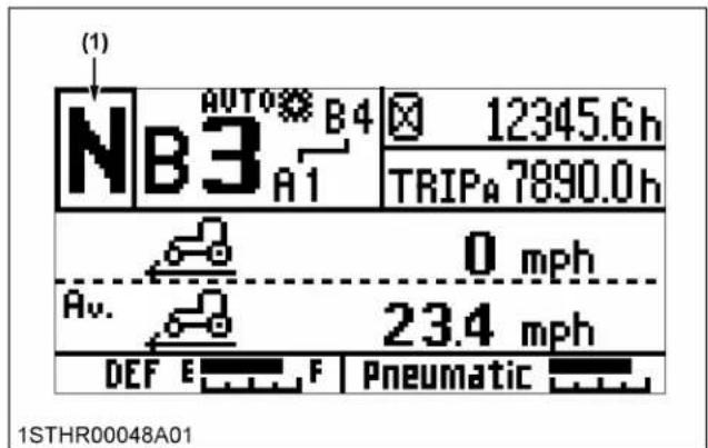
(1) "NEUTRAL"

(1) Message
(2) Error display (power shift transmission)
5. Shuttle button
Hold down the shuttle enable button and press the shuttle button to switch forward and reverse travel.
Standard, Deluxe model

(1) Shuttle button
(2) Shuttle enable button
(F) "FORWARD"
(R) "REVERSE"
Premium, Premium KVT model

(1) Shuttle button
(2) Shuttle enable button
(F) "FORWARD"
(R) "REVERSE"
NOTE :
- Either the shuttle lever or the shuttle button, whichever is activated later, is given priority. If the tractor is moving forward with the forward shuttle button and the shuttle lever is moved to reverse, for example, the tractor switches to reverse.
6. Shuttle neutral button
Press this button to return the transmission to the "NEUTRAL" position.
Standard, Deluxe model

(1) Shuttle neutral button
Premium, Premium KVT model

(1) Shuttle neutral button
NOTE :
- Even when the shuttle lever is shifted to the "FORWARD" or "REVERSE" position, pressing the button puts the transmission to the "NEUTRAL" position.
7. Creep speed (if equipped)

WARNING
To avoid personal injury or death:
- When you leave the tractor, be sure to apply the parking brake and stop the engine.
• In applying the brakes:
- The torque of the wheel axle is extremely high while creep speed is being used. Be sure to step down on the clutch pedal completely before applying the brakes, or the torque will overcome the brakes.
- When starting to operate the tractor, be sure to release the parking brake.
Misuse of the brakes may cause damage to the transmission and is therefore not acceptable to KUBOTA for coverage under the warranty.
Operating the creep gear shift lever
- Stop the tractor and step on the clutch pedal.
- Pull up the creep gear shift lever, and the creep mode turns on. Push it down to turn off the creep mode.
- In creep mode ("ON"-OFF"), the following speed gears can be used.
| Creep gear shift lever | Gear shift | Remarks | |
| Forward (54 speeds) | Reverse (27 speeds) | ||
| Creep “ON” 24 | speeds 12 speeds | *1 | |
| Creep “OFF” 30 | speeds 15 speeds | *2 | |
*1 Forward: main gear shift 1 to 6th, range gear shift A to D. Reverse: main gear shift 1 to 3rd, range gear shift A to D.
*2 Forward: main gear shift 1 to 6th, range gear shift A to E. Reverse: main gear shift 1 to 3rd, range gear shift A to E.

(1) Creep gear shift lever
(A) ...Creep "ON"
(B) ...Creep "OFF"
IMPORTANT :
- During use at creep speed, avoid using the auto shift mode.
- Press the clutch pedal completely down and stop the tractor's motion before shifting the creep gear shift lever.
- If starting is attempted with the creep gear shift lever not fully shifted, [N - -] will be displayed on the LCD monitor.
If [N - -] is displayed, confirm that the creep gear shift lever is fully shifted, and then step on the clutch pedal to reset the gear shift.
Creep speed should be used only when doing one of the following jobs:
- Deep rotary-tilling and harrowing
- Planting
- Turf application
Creep speed cannot be used for any of the followings:
- Pulling a trailer
- Front-loader operation
-
Front-blade operation
-
Earth-moving
- Entering and leaving a field
- Loading onto and unloading from a truck
8. 4WD and AUTO 4WD switch

WARNING
To avoid personal injury or death:
- Do not engage the front-wheel drive when traveling at road speed.
- When driving on icy, wet, or loose surfaces, make sure the tractor is correctly ballasted to avoid skidding and loss of steering control. Operate at reduced speed and engage front-wheel drive.
- 4WD model tractor is equipped with 4-wheel braking and appropriate care should be taken during hard braking.
- An accident may occur if the tractor is suddenly braked, such as by heavy towed loads shifting forward or loss of control.
- The braking characteristics are different between 2 and 4-wheel drive tractor models. Be aware of the difference and use carefully.
8.1 Selection of 4WD modes
Select one of the following modes for driving the front wheels according to the type of job.
| Mode | |||
| AUTO 4WD mode | The 4WD and 2WD modes switch themselves according to the travel speed and the front wheel turning angle. | ||
| Traveling speed | Front wheel turning angle | Front wheel drive | |
| Below 10 km/h (6.2 mph) | Approx. 15° or less | 4WD | |
| Approx. 15° or more | 2WD | ||
| Between 10 and 20 km/h (6.2 and 12.4 mph) or so | Approx. 10° or less | 4WD | |
| Approx. 10° or more | 2WD | ||
| Above 20 km/h (12.4 mph) | — 2WD | ||
| Manual 4WD mode | The front and rear wheels are always driven. | ||
| 2WD mode The | rear wheels only are always driven. | ||
8.2 Switching of 4WD modes
For Standard, Deluxe models:
- Press the top half of the 4WD switch, and the AUTO 4WD mode is selected and the indicator on the instrument panel lights up.
- Press the bottom half of the 4WD switch, and the manual 4WD mode is selected and the indicator on the instrument panel lights up.
- Return the 4WD switch to a central position, and the 2WD mode is selected and the indicator goes off.

(1) 4WD switch
(A) AUTO 4WD mode
(B) Manual 4WD mode
(C) 2WD mode
For Premium, Premium KVT models:
- Each time the 4WD button is pressed, the "Manual 4WD" and "2WD" mode are switched alternately. If the 4WD mode is selected, the indicator on the instrument panel lights up.
Switching to the "AUTO 4WD" mode can be made with the K-monitor.
(See Setting the drivability on page 77.)

(1) 4WD button
(A) "PUSH"
NOTE :
- The 4WD button can be operated when the tractor is on the go or at rest without depressing the clutch.
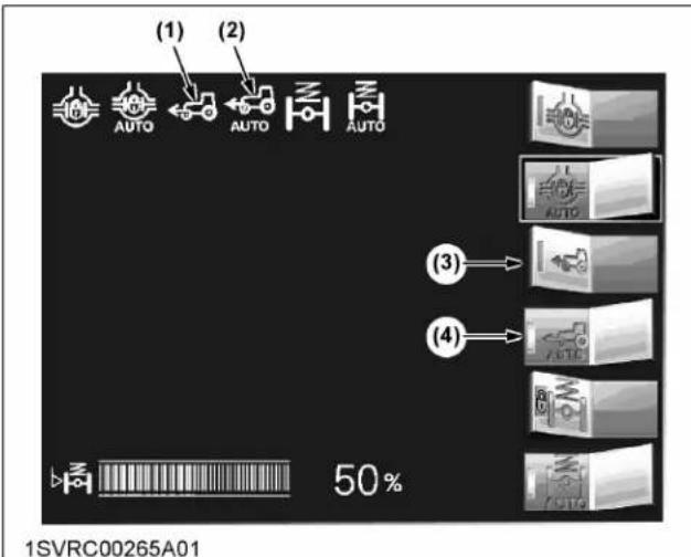
When the AUTO 4WD or manual 4WD mode is selected, the indicator on the instrument panel lights up.

(1) 4WD indicator
8.4 Front-wheel drive usage
Front-wheel drive is effective for the following jobs:
- When greater pulling force is needed, such as working in a wet field, when pulling a trailer, or when working with a front-end loader.
- When working in sandy soil.
- When working on hard soil where a rotary tiller might push the tractor forward.
- For increased braking at reduced speed.
IMPORTANT :
- Tires will wear quickly if the front-wheel drive is engaged on paved roads.
9. Differential lock
WARNING
To avoid personal injury or death due to loss of steering control:
- Do not operate the tractor at high speed with differential lock engaged.
- Do not attempt to turn with the differential lock engaged.
- Be sure to release the differential lock before making a turn in field conditions.
9.1 Selection of differential lock modes
Select any of the following differential lock modes as required.
| Mode | |||
| AUTO differential lock mode | The differential lock turns itself on and off in response to the following conditions. | ||
| Traveling speed | Front wheel turning angle | 4-wheel differential lock | |
| Below 10 km/h (6.2 mph) | Approx. 15irc or less | ON | |
| Approx. 15irc or more | OFF | ||
| Between 10 and 20 km/h (6.2 and 12.4 mph) or so | Approx. 10irc or less | ON | |
| Approx. 10irc or more | OFF | ||
| Above 20 km/h (12.4 mph) | — OFF | ||
| Manual differential lock mode | The 4 wheels are always put in the differential lock mode. | ||
| Differential lock OFF mode | The 4 wheels are always out of the differential lock mode. | ||
9.2 Switching of differential lock modes
For Standard, Deluxe models:
- Press the top half of the differential lock switch, and the AUTO differential lock mode is selected and the indicator on the instrument panel lights up.
- Press the bottom half of the differential lock switch, and the manual differential lock mode is selected and the indicator on the instrument panel lights up.
- Return the differential lock switch to a central position, and the differential lock mode turns off and the indicator goes off.
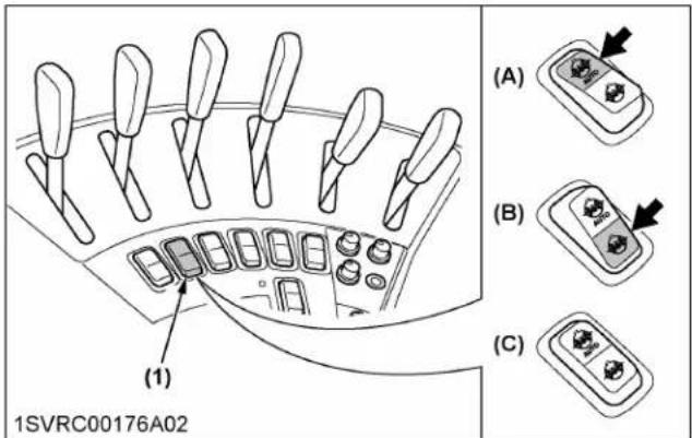
(1) Differential lock switch (A) AUTO differential lock mode
(B) Manual differential lock mode
(C) Differential lock OFF mode
For Premium, Premium KVT models:
- Each time the differential lock button is pressed, the manual differential lock mode turns "ON" or "OFF". If this mode is "ON", the indicator on the instrument panel lights up.
Switching to the "AUTO differential lock" mode can be done with the K-monitor.
(See Setting the drivability on page 77.)
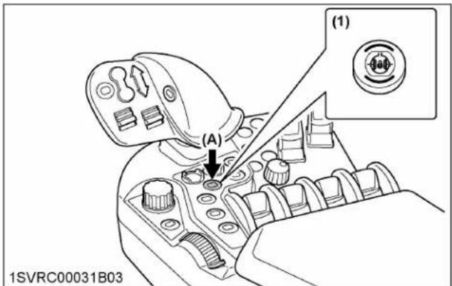
(1) Differential lock button (A) "PUSH"

(1) Differential lock indicator
(2) AUTO differential lock indicator
(3) Differential lock switch
(4) AUTO differential lock switch
9.3 Differential lock indicator
When the AUTO differential lock or manual differential lock mode is selected, the indicator on the instrument panel lights up.
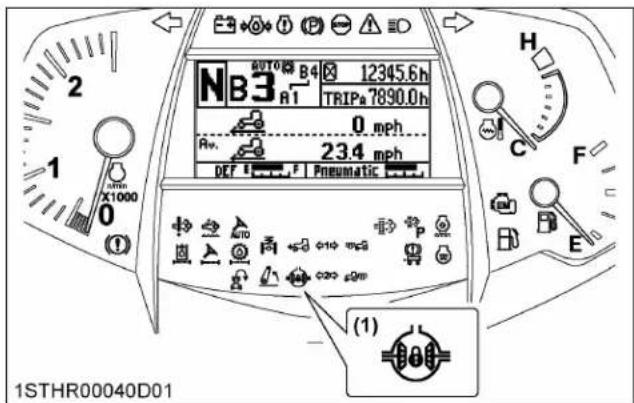
(1) Differential lock indicator
IMPORTANT :
- When using the differential lock, always slow the engine down.
• To prevent damage to power train, do not engage differential lock when one wheel is spinning and the other is completely stopped. - If the differential lock cannot be released, step lightly on the brake pedals alternately.
This machine is equipped with an electronic transmission for 30-speed change in forward and 15-speed change in reverse motion.

WARNING
To avoid personal injury or death:
- The ez-command center has no neutral position. To bring the tractor to a complete stop, step on the brake pedal or set the shuttle lever to neutral.
With the optional creep device in place, the traveling speed can be changed by up to 54th in forward and 27th in reverse stages. Further, in road and field modes, the "auto shift" mode as well as the "manual" mode may be selected.
In the auto shift mode, the optimum traveling speed can be automatically selected by electronic control within the operator-preset speed range. Thanks to this mode, no troublesome gear shifting is required any longer, allowing the operator to concentrate on his or her job. The gear shift sensitivity in response to the engine load and other settings may also be flexibly made. With this, PTO-driven and towed implements are operated with high accuracy in an eco-friendly way.
In the maximum traveling speed range, the overdrive mechanism works for the engine to run at medium rpm but for the machine to travel at maximum speed. In short, this helps to run the machine economically.
When starting the engine, the meter panel LCD shows [N - -]. Depress the clutch pedal. The minimum gear speed (A1) will be automatically displayed. Depress the clutch pedal after starting the engine, as shuttle operation is not possible with [N - -] still displayed.
Standard, Deluxe model

(1) Ez-command center
(2) Shuttle enable button
(3) Range gear shift button
(4) Auto shift button
(5) Shuttle neutral button
(6) Transmission mode select switch
(7) Auto shift sensitivity dial
Premium model

(1) Ez-command center
(2) Shuttle enable button
(3) Range gear shift button
(4) Auto shift button
(5) Shuttle neutral button
(6) Transmission mode select switch
1. Switching the operation modes
When the engine gets started, the manual mode is selected all the time.
Every time the auto shift button is pressed, the auto shift mode and the manual mode are switched alternately. Which mode is now on can be checked with the LCD indicator on the instrument panel.
However, when the gear shift range in auto shift mode memory is other than the minimum gear shift (A-1), it will not switch to auto shift mode even when you press the auto shift button.
After switching the main gear shift and range gear shift with the ez-command center until within the gear shift range in memory, press the auto shift button to switch to auto shift mode.
Example:
When the gear shift range in auto shift mode memory is B-1 to B-3
| Current gear shift | Press the auto shift button |
| A-1 | Does not switch to auto shift mode |
| B-1 or B-2 or B-3 | Switches to auto shift mode |
| B-4 | Does not switch to auto shift mode |
Standard, Deluxe model
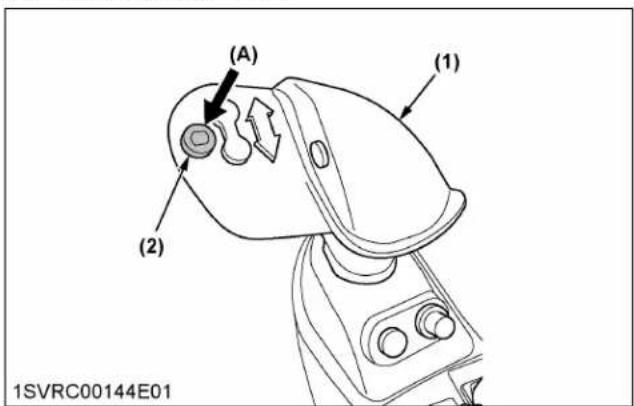
(1) Ez-command center
(2) Auto shift button
Premium model

(1) Ez-command center
(2) Auto shift button
NOTE :
- The auto shift button functions without any clutch operation, whether the machine is running or at a stop.
- When the engine stops during work, the gear shift previous to the stop will be selected if you step on the clutch pedal after restarting without turning the key switch off. If you turn the key switch off before restarting, the minimum gear shift (A-1) will be selected.
2. Switching the auto shift modes
According to the type of work, switch the transmission mode select switch to the "road mode" or "field mode".
The currently enabled mode can be checked with the LCD indicator on the instrument panel.
Before switching the modes, get the engine started first and then set the shuttle lever to the neutral position.
| Transmission mode select switch | Type of work |
| Road mode | Used for traveling on public roads and towing light-duty implements |
| Field mode | Used for general heavy-load implements. |
Standard, Deluxe model

(1) Transmission mode select switch
(A) "road mode"
(B) "field mode"
Premium model
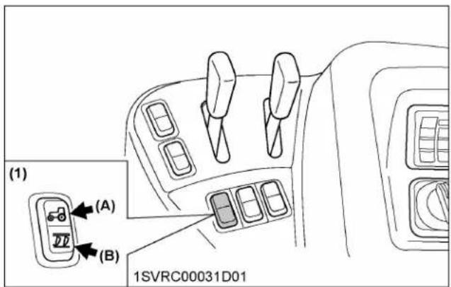
(1) Transmission mode select switch
(A) "road mode"
(B) "field mode"
Instrument panel (all models)
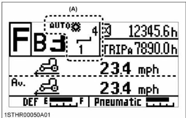
(A) "Auto shift-field mode"

(B) "Auto shift-road mode"

(C) "Manual mode"
3. Traveling speeds
3.1 Setting the traveling speed gear in the road mode (Standard, Deluxe model)
- Referring to the traveling speed ranges chart, determine maximum and minimum traveling speeds that are best suited for the type of work. On the automatic gear shift (road mode) setting screen, enter a desired traveling speed range.
Traveling speed ranges
| Main gear shift | Lower speed |  1st → 2nd → 3rd → 4th → 5th → 6th 1st → 2nd → 3rd → 4th → 5th → 6th | Higher speed |
| Range gear shift | Lower speed range |  A → B → C → D → E A → B → C → D → E | Higher speed range |
- The automatic gear shifting will be within the preset traveling speed range.
Details regarding relevant settings can be found in a different section.
(See Setting the power shift transmission
(Standard, Deluxe model) on page 50.)
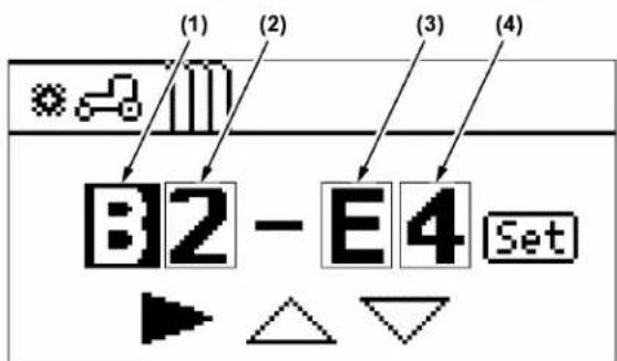
1STHR00128A01
(1) Range gear shift for minimum traveling speed
(2) Main gear shift for minimum traveling speed
(3) Range gear shift for maximum traveling speed
(4) Main gear shift for maximum traveling speed
NOTE :
- Suppose that while the machine is running, the traveling speed is increased or decreased out of its preset range with the ez-command center. When this happens, the manual mode is resumed. To go back to the auto shift mode, get the traveling speed back into the preset range and press the auto shift button again.
3.2 Setting the main gear shift range in the field mode (Standard, Deluxe model)
- Referring to the traveling speed ranges chart, determine maximum and minimum main gear shifts that are best suited for the type of work. On the automatic gear shift (field mode) setting screen, enter desired traveling speeds.
Traveling speed ranges
| Main gear shift | Lower speed |  1st → 2nd → 3rd → 4th → 5th → 6th 1st → 2nd → 3rd → 4th → 5th → 6th | Higher speed |
| Range gear shift | Lower speed range |  A → B → C → D → E A → B → C → D → E | Higher speed range |
- The automatic gear shifting will be within the preset traveling speed range.
Details regarding relevant settings can be found in a different section.
(See Setting the automatic gear shift (field mode) on page 51.)

(1) Minimum main gear shift
(2) Maximum main gear shift
NOTE :
- The automatic gear shift range in the field mode may be preset only for the main gear shift.
- Suppose that while the machine is running, the traveling speed is increased or decreased out of its preset range with the ez-command center. When this happens, the manual mode is resumed. To go back to the auto shift mode, get the traveling speed back into the preset range and press the auto shift button again.
3.3 Setting the range gear shift in the field mode (Standard, Deluxe model)
- The range gear shift consists of 5 speeds. Determine the range gear shift range that is best suited for the working speed.
- Hold down the range gear shift button and push the ez-command center forward, and the range gear shift goes up. Pull this lever backward, and this shift comes down.
Before setting the range gear shift in the field mode, bring the tractor to a complete stop.
The selected range gear shift stage can be checked with the LCD indicator on the instrument panel.
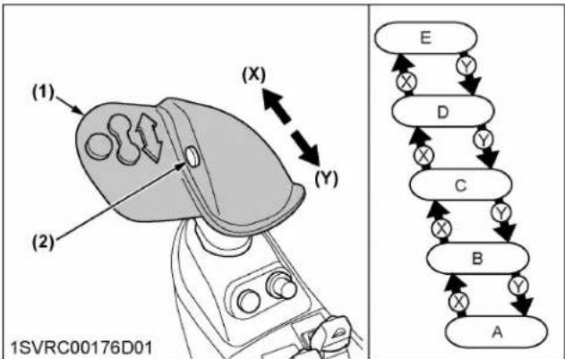
flowchart
graph TD
    A["1SVRC00176D01"] --> B["(1)"]
    A --> C["(2)"]
    B --> D["(X)"]
    C --> E["(Y)"]
    D --> F["(Z)"]
    E --> G["(Z)"]
(1) Ez-command center
(2) Range gear shift button
(X) "Shift up"
(Y) "Shift down"
3.4 Setting the traveling speed range in the road mode (Premium model)
- Referring to the traveling speed ranges chart, determine maximum and minimum traveling speeds that are best suited for the type of work. On the K-monitor screen, enter desired traveling speeds.
Traveling speed ranges
| Main gear shift | Lower speed |  1st → 2nd → 3rd → 4th → 5th → 6th 1st → 2nd → 3rd → 4th → 5th → 6th | Higher speed |
| Range gear shift | Lower speed range |  A → B → C → D → E A → B → C → D → E | Higher speed range |
- The automatic gear shifting will be within the preset traveling speed range.
Details regarding relevant settings can be found in a different section.
(See Setting the traveling speed gear in the road mode on page 81 and Setting the traveling speed gear in the field mode on page 81.)

flowchart
graph TD
    A["0"] --> B["1"]
    B --> C["2"]
    C --> D["3"]
    D --> E["4"]
    E --> F["5"]
    F --> G["6"]
    G --> H["7"]
    H --> I["8"]
    I --> J["9"]
    J --> K["10"]
    K --> L["11"]
    L --> M["12"]
    M --> N["13"]
    N --> O["14"]
    O --> P["15"]
    P --> Q["16"]
    Q --> R["17"]
    R --> S["18"]
    S --> T["19"]
    T --> U["20"]
    U --> V["21"]
    V --> W["22"]
    W --> X["23"]
    X --> Y["24"]
    Y --> Z["25"]
1SVRC00295A01
(1) Selected traveling speed gear shift
(2) Previous screen resume switch
(3) Low-speed slider
(4) High-speed slider
(5) High-speed setting switch
(6) Low-speed setting switch
(7) Main gear shift section
(8) Range gear shift section (A to E)
NOTE :
- Suppose that while the machine is running, the traveling speed is increased or decreased out of its preset range with the ez-command center. When this happens, the manual mode is resumed. To go back to the auto shift mode, get the traveling speed back into the preset range and press the auto shift button again.
3.5 Setting the main gear shift range in the field mode (Premium model)
- Referring to the traveling speed ranges chart, determine maximum and minimum main gear shifts that are best suited for the type of work. On the K-monitor screen, enter a desired main gear shift range.
Traveling speed ranges
| Main gear shift | Lower speed | Higher speed |
| 1st → 2nd → 3rd → 4th → 5th → 6th | ||
| Range gear shift | Lower speed range | Higher speed range |
| A → B → C → D → E | ||
- The automatic gear shifting will be within the preset main gear shift range.
Details regarding relevant settings can be found in a different section.
(See Setting the traveling speed gear in the road mode on page 81 and Setting the traveling speed gear in the field mode on page 81.)

flowchart
graph TD
    A["1-4"] --> B["(1)"]
    B --> C["6"]
    C --> D["5"]
    D --> E["4"]
    E --> F["3"]
    F --> G["2"]
    G --> H["1"]
    H --> I["(7)"]
    J["(2)"] --> K["×"]
    K --> L["(3)"]
    L --> M["+"]
    M --> N["(4)"]
    N --> O["+"]
    O --> P["(5)"]
    P --> Q["MAX *"]
    Q --> R["(6)"]
    R --> S["MIN"]
    S --> T["−"]
    T --> U["(3)"]
    U --> V["−"]
    V --> W["(4)"]
    W --> X["(6)"]
1SVRC00296A01
(1) Selected traveling speed gear shift
(2) Previous screen resume switch
(3) Low-speed setting switch
(4) High-speed setting switch
(5) High-speed slider
(6) Low-speed slider
(7) Main gear shift section (1 to 6)
NOTE :
- The automatic gear shift range in the field mode may be preset only for the main gear shift.
- Suppose that while the machine is running, the traveling speed is increased or decreased out of its preset range with the ez-command center. When this happens, the manual mode is resumed. To go back to the auto shift mode, get the traveling speed back into the preset range and press the auto shift button again.
3.6 Setting the range gear shift in the field mode (Premium model)
-
The range gear shift consists of 5 speeds. Determine the range gear shift range that is best suited for the working speed.
-
Hold down the range gear shift button and push the ez-command center forward, and the range gear shift goes up. Pull this lever backward, and this shift comes down.
Before setting the range gear shift in the field mode, bring the tractor to a complete stop.
The selected range gear shift stage can be checked with the LCD indicator on the instrument panel.

flowchart
graph TD
    A["1SVRC00031H01"] --> B["(1)"]
    B --> C["(2)"]
    C --> D["(X)"]
    D --> E["(Y)"]
    E --> F["E"]
    F --> G["D"]
    G --> H["C"]
    H --> I["B"]
    I --> J["A"]
    style A fill:#f9f,stroke:#333
    style B fill:#ccf,stroke:#333
    style C fill:#cfc,stroke:#333
    style D fill:#fcc,stroke:#333
    style E fill:#cff,stroke:#333
    style F fill:#ffc,stroke:#333
    style G fill:#cfc,stroke:#333
    style H fill:#fcc,stroke:#333
    style I fill:#cfc,stroke:#333
    style J fill:#fcc,stroke:#333
(1) Ez-command center
(2) Range gear shift button
(X) "Shift up"
(Y) "Shift down"
4. Operating in the manual mode
To operate the machine in the manual mode, it is necessary to switch from the auto shift mode to the manual mode.
-
Hold down the auto shift button to select the manual mode.
-
To switch between the road and field modes, use the transmission mode select switch.
Standard, Deluxe model

(1) Ez-command center
(2) Auto shift button
(A) "PUSH"
Premium model
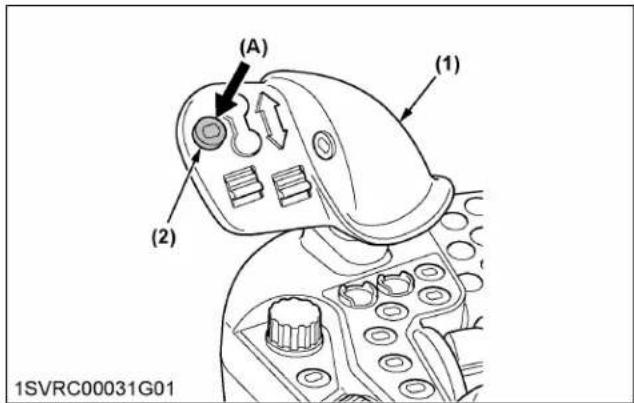
(1) Ez-command center
(2) Auto shift button
(A) "PUSH"
4.1 Operating the main gear shift
This gear shift can be carried out without any clutch operation, whether the tractor is running or at a stop.
-
Push the ez-command center forward stage by stage, and the traveling speed shifts up one by one.
-
Pull it backward stage by stage, and the traveling speed shifts down one by one.
The selected main gear shift stage can be checked with the LCD indicator on the instrument panel. It should be noted that the number of gear shifts varies with the modes:
- With field mode selected: Shifting is possible only among the 6 gears in forward, and 3 gears in reverse speed of the main gear shift.
- With road mode selected: Shifting is possible only among the 30 gears in forward, and 15 gears in reverse speed across the main gear shift and range gear shift.
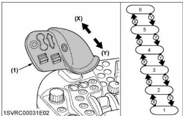
(1) Ez-command center (X) "Shift up"
(Y) "Shift down"
4.2 Operating the range gear shift
The range gear shifting works for 5 speeds.
-
Hold down the range gear shift button.
-
In this state, push the ez-command center forward stage by stage, and the range traveling speed shifts up one by one.
-
Pull it backward stage by stage, the range traveling speed shifts down one by one.
The selected range gear shift stage can be checked with the LCD indicator on the instrument panel.
NOTE :
• To start the tractor at a specific speed, determine the range gear shift and main gear shift settings and use the clutch pedal or the shuttle lever.
• In doing a light-duty job in the road mode, the range gear shifting can be made without having to stop the tractor. As well, you can switch the range gear shift without pressing the range gear shift button.

flowchart
graph TD
    A["Component 1: Valve with labeled parts (A), (B), (C), (D), (E)"] --> B["Arrow to (X)"]
    B --> C["Arrow to (Y)"]
    C --> D["Arrow to (X)"]
    D --> E["Arrow to (Y)"]
    E --> F["Arrow to (X)"]
    F --> G["Arrow to (Y)"]
    G --> H["Arrow to (X)"]
    H --> I["Arrow to (Y)"]
    I --> J["Arrow to (X)"]
    J --> K["Arrow to (Y)"]
    K --> L["Arrow to (X)"]
    L --> M["Arrow to (Y)"]
    M --> N["Arrow to (X)"]
    N --> O["Arrow to (Y)"]
    O --> P["Arrow to (X)"]
    P --> Q["Arrow to (Y)"]
    Q --> R["Arrow to (X)"]
    R --> S["Arrow to (Y)"]
    S --> T["Arrow to (X)"]
    T --> U["Arrow to (Y)"]
    U --> V["Arrow to (X)"]
    V --> W["Arrow to (Y)"]
    W --> X["Arrow to (X)"]
    X --> Y["Arrow to (Y)"]
    Y --> Z["Arrow to (X)"]
    Z --> AA["Arrow to (Y)"]
    AA --> AB["Arrow to (X)"]
    AB --> AC["Arrow to (Y)"]
    AC --> AD["Arrow to (X)"]
    AD --> AE["Arrow to (Y)"]
    AE --> AF["Arrow to (X)"]
    AF --> AG["Arrow to (Y)"]
    AG --> AH["Arrow to (X)"]
    AH --> AI["Arrow to (Y)"]
    AI --> AJ["Arrow to (X)"]
    AJ --> AK["Arrow to (Y)"]
    AK --> AL["Arrow to (X)"]
    AL --> AM["Arrow to (Y)"]
    AM --> AN["Arrow to (X)"]
    AN --> AO["Arrow to (Y)"]
    AO --> AP["Arrow to (X)"]
    AP --> AQ["Arrow to (Y)"]
    AQ --> AR["Arrow to (X)"]
    AR --> AS["Arrow to (Y)"]
    AS --> AT["Arrow to (X)"]
    AT --> AU["Arrow to (Y)"]
    AU --> AV["Arrow to (X)"]
    AV --> AW["Arrow to (Y)"]
    AW --> AX["Arrow to (X)"]
    AX --> AY["Arrow to (Y)"]
    AY --> AZ["Arrow to (X)"]
    AZ --> BA["Arrow to (Y)"]
    BA --> BB["Arrow to (X)"]
    BB --> BC["Arrow to (Y)"]
    BC --> BD["Arrow to (X)"]
    BD --> BE["Arrow to (Y)"]
    BE --> BF["Arrow to (X)"]
    BF --> BG["Arrow to (Y)"]
    BG --> BH["Arrow to (X)"]
    BH --> BI["Arrow to (Y)"]
    BI --> BJ["Arrow to (X)"]
    BJ --> BK["Arrow to (Y)"]
    BK --> BL["Arrow to (X)"]
    BL --> BM["Arrow to (Y)"]
    BM --> BN["Arrow to (X)"]
    BN --> BO["Arrow to (Y)"]
    BO --> BP["Arrow to (X)"]
    BP --> BQ["Arrow to (Y)"]
    BQ --> BR["Arrow to (X)"]
    BR --> BS["Arrow to (Y)"]
    BS --> BT["Arrow to (X)"]
    BT --> BU["Arrow to (Y)"]
    BU --> BV["Arrow to (X)"]
    BV --> BW["Arrow to (Y)"]
    BW --> BX["Arrow to (X)"]
    BX --> BY["Arrow to (Y)"]
    BY --> BZ["Arrow to (X)"]
    BZ --> CA["Arrow to (Y)"]
    CA --> CB["Arrow to (X)"]
    CB --> CC["Arrow to (Y)"]
    CC --> CD["Arrow to (X)"]
    CD --> CE["Arrow to (Y)"]
    CE --> CF["Arrow to (X)"]
(1) Ez-command center
(A) "PUSH"
(2) Range gear shift button
(X) "Shift up"
(Y) "Shift down"
5. Example of operation on combined auto-shift-and-manual mode
Starting the auto-shift-mode run
- Set the traveling speed range (9th through 12th, for example) according to the type of work. Then start the tractor.
- The automatic operation will go on in response to the load within this preset traveling speed range.
Switching to the manual-mode run
- After pressing the auto shift button to switch to manual mode, shift gears according to work conditions and carry out operation.
If you use the ez-command center to shift up or down beyond the gear range set in auto shift mode, the mode will switch to manual.
Returning to the auto-shift-mode run
- If the current traveling speed range in the manual mode is within the auto-shift-mode-preset traveling speed range (9th through 12th), press the auto shift button, and the auto shift mode is resumed.
- If the traveling speed is out of its preset range, first return it to its preset range. Then press the auto shift button.
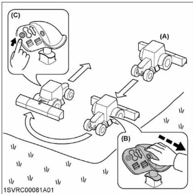
flowchart
graph TD
    A["Robot with hand icon"] --> B["Robot with hand icon"]
    B --> C["Robot with hand icon"]
    C --> D["Robot with hand icon"]
    D --> E["Robot with hand icon"]
    E --> F["Robot with hand icon"]
    style A fill:#f9f,stroke:#333
    style B fill:#ccf,stroke:#333
    style C fill:#cfc,stroke:#333
    style D fill:#fcc,stroke:#333
    style E fill:#cff,stroke:#333
    style F fill:#ffc,stroke:#333
(A) "Auto shift mode"
(B) "Switching to the manual-mode"
(C) "Auto shift mode"
6. Setting the auto shift sensitivity
The auto shift sensitivity can maintain the engine rpm for the gear shifting up/down.
When the sensitivity is set at a lower position, the gear shifting is maintained by lower engine rpm, and when set at a higher position, the gear shifting is maintained by higher engine rpm.
When running in the auto shift mode
Refer to the following table for settings according to the job.
- Eco-friendly operation
The gear is automatically shifted up/down in lower engine rpm.
• Power required operation
The gear is automatically shifted up/down in higher engine rpm.
| Operating | Auto shift sensitivity dial (Standard, Deluxe model) Auto shift sensitivity control (Premium model) | Remarks |
| Eco-friendly operation | Turn the dial counterclockwise.Rettract the graph leftward with the “Minus (-)” switch. | Suited for light-duty work |
| Power required operation | Turn the dial clockwise.Extend the graph rightward with the “Plus (+)” switch. | Suited for heavy-duty work |
When running in the manual operation of the road mode
During operation, the main gear shift automatically selected when shifting the range gear shift up or down changes with the auto shift sensitivity setting.
Gear shifting example when shifting up
| Range gear shift | Main gear shift | |
| C | -6 |  |
| C | -5 | |
| C | -4 | |
| C | -3 | |
| C | -2 | |
| C | -1 | |
| B | -6 | |
| B | -5 | |
| B | -4 | |
| B | -3 | |
| B | -2 | |
| B | -1 | |
| A | -6 | |
| Operating Light-duty Heavy-duty | ||
| Auto shift sensitivity dial(Standard, Deluxe model) |   | |
| Auto shift sensitivity control(Premium model) |   | |
| Remarks | Some of the tractor's traveling speeds (1st to 30th) are not in proportion to the gear shift range. | |
NOTE :
- If you step on the clutch pedal immediately after shifting the range gear shift up or down, the
main gear shift may be automatically shifted as follows:
- The main gear shift is shifted down (6 to 1) as the speed decreases.
- When coming to a complete stop, speed 1 is selected.
Standard, Deluxe model

(1) Auto shift sensitivity dial (A) "Heavy-duty"
(B) "Light-duty"
Premium model

(1) Auto shift sensitivity control
(A) "Heavy-duty"
(2) Plus (+) switch
(B) "Light-duty"
(3) Minus (-) switch
NOTE :
- Details regarding the engine and transmission settings can be found in a different section.
(See Setting the auto shift sensitivity on page 83.)
7. Limp home switch
If the transmission has trouble, press this switch, and the tractor can be moved for an emergency escape.
-
Press the (F) or (R) switch to enter limp home mode.
-
In traveling stop status, press the (F) or (R) switch to move at a fixed speed while the switch is held down. The speed will also increase if you step on the foot throttle while traveling.
- When switching traveling directions, press the (F) or (R) switch after coming to a complete stop.
- Step on the clutch pedal to stop.
NOTE :
- Depending on trouble spots, the tractor may fail to run as expected.
- Park it in a safe place and immediately contact your local KUBOTA Dealer.
- If you press the (F) or (R) switch by mistake, turn the key switch off to leave limp home mode.
Standard, Deluxe model

(1) Limp home switch forward (F)
(2) Limp home switch reverse (R)
Premium, Premium KVT model
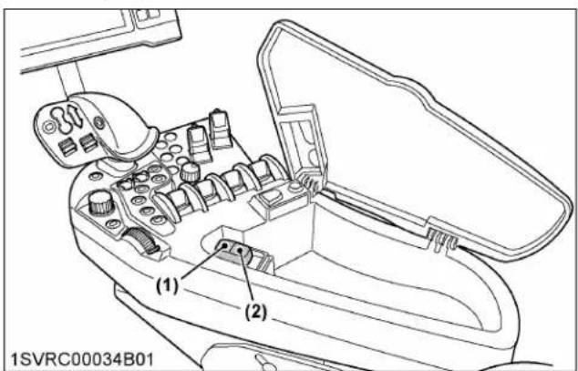
(1) Limp home switch forward (F)
(2) Limp home switch reverse (R)
CONTINUOUSLY VARIABLE TRANSMISSION (CVT) CONTROL

WARNING
To avoid personal injury or death:
- The ez-command center has no neutral position. To bring the tractor to a complete stop, step on the brake pedal or set the shuttle lever to neutral.
The continuously variable transmission (CVT) is a fully computerized stepless type. Depending on the type of work, there are two modes to choose from: automatic and manual engine speed setting
Other settings are also possible at will, including CVT sensitivity in response to engine load, response control for start and stop, and cruise control among others.

(1) Ez-command center
(2) Cruise button
(3) Ratio lock button
(4) Mode shift button
(5) Shuttle neutral button
(6) Shuttle enable button
(7) Limp home switch
1. Traveling operation
Traveling speed control for a tractor with CVT can be operated with either the ez-command center or the foot throttle. Choose between them according to the job.
You can control both the speed and the engine power by how deeply you step on the foot throttle, as with an automatic transmission car; this enables convenient operation of the trailer and so on.
NOTE :
- Operating the traveling speed control using the foot throttle requires the selection of "automatic mode".
(See Operation of the automatic mode on page 158.)
1.1 Main shift
With the ez-command center, the machine can be sped up and slowed down easily.
Push the lever forward and pull it backward, and the traveling speed will increase and decrease respectively.
The traveling speed is fixed at the position where you release the lever.
The traveling speed changes in proportion to the duration of moving the lever. The longer the lever is pushed forward, for instance, the higher the traveling speed becomes.
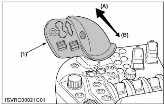
(1) Ez-command center (A) "SPEED UP"
(B) "SLOW DOWN"
NOTE :
- The ez-command center has no "NEUTRAL" position. Even when the lever is set at the lowest speed position, the machine runs at the creep speed at about 0.5 km/h (0.3 mph). To bring the tractor to a complete stop, step on the brake pedal or set the shuttle lever to "NEUTRAL".
- Allowing for conditions, use the cruise mode when you want to make fine adjustments to the traveling speed, or to keep the traveling speed steady for a job with a high traction load on the tractor.
(See Cruise control on page 161.)
- When the ez-command center is pushed forward during the tractor driving by using foot throttle, the traveling speed is set at the time of ez-command center operation. But this setting is effective for only when the tractor has a light load.
1.2 Mode shift
Every time the mode shift button is pressed, the "high speed" and "low speed" modes switch alternately. Depending on this selection, the "traveling enable upper limit speed", shown with the LCD indicator on the instrument panel, is also switched.

(1) Ez-command center
(A) "PUSH"
(2) Mode shift button
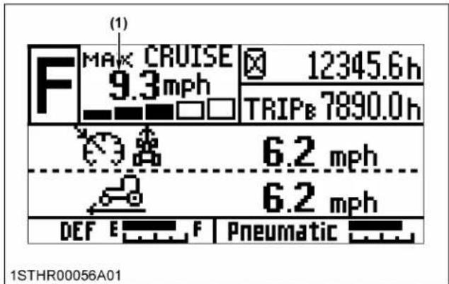
(1) "Traveling enable upper limit speed"
NOTE :
- Switching from the high speed mode to the low speed mode is not possible if the current traveling speed is higher than the maximum traveling speed set in the low speed mode; a buzzer will sound if this is tried.
1.3 Modifying the maximum traveling speed
Maximum traveling speed controlled with the ez-command center has been factory-set as follows. The mode shift's "low speed" range alone can be modified for its highest traveling speed.
Factory-set traveling speeds
- Mode shift (low):
Maximum traveling speed up to 15 km/h (9 mph) - Mode shift (high):
Maximum traveling speed up to 40 to 50 km/h (25 to 30 mph)
Modifying the low-range traveling speeds
Set the desired traveling speed while confirming its digital display.
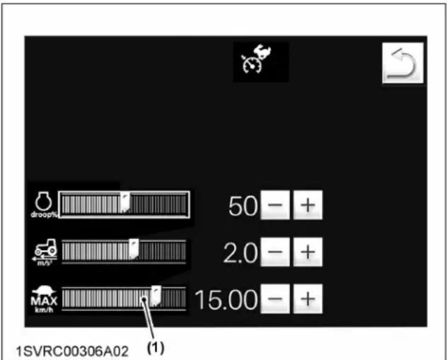
(1) CVT low-range maximum speed setting
NOTE :
- Details regarding relevant settings can be found in a different section. (See Modifying the CVT low-range maximum speed setting on page 87.)
- Example: In the case of working at the 4-6 km/h (3-4 mph) traveling speed, preferably set the low-range maximum traveling speed to about 10 km/h (6 mph). With this setting, the traveling speed can be kept at a nearly constant level (S) in response to the ez-command center movement (T). In this way, the speed is easy to finely adjust with the lever.

line
| Point | X | Y | |-------|----|----| | A | 1 | 15 | | B | 5 | 6 |(X) Operating times of ez-command center
(Y) Traveling speed (km/h)
(A) Low-range speed of the factory-setting (15 km/h / 9 mph)
(B) Modified low-range speed (10 km/h / 6 mph)
2. Operation of the automatic mode
This mode is mainly utilized for traveling on public roads and towing plows and similar implements.
The optimum traveling speed and engine power are obtained according to the speed settings made with the ez-command center, foot throttle, and CVT sensitivity settings.
(See Setting the continuously variable transmission (CVT) sensitivity on page 160.)
NOTE :
- In the automatic mode, the engine rpm also fluctuates with changes in load. Therefore this mode is not suited for PTO-driven operations.
Switching to the automatic mode
- Set the shuttle lever to "NEUTRAL" or press the shuttle neutral button.
- Set the hand throttle close to minimum speed, and the automatic mode is selected.
Even during operation, do not move the hand throttle.
Foot throttle operation (for example: trailer work)
- You can control both the speed and the engine power by how deeply you step on the foot throttle, as with an automatic transmission car.
- Release your foot from the foot throttle pedal, and the tractor slows down.
- To bring the tractor to a complete halt, step on the brake pedal.
When you release the brake pedal, the tractor starts running.
Ez-command center operation (for example: plow work)
- Set a desired traveling speed with the ez-command center, and the engine power is controlled to keep up this speed.
- Step on the both brake pedals to stop the tractor. When releasing the pedals to start, the traveling speed must be reset. When stopped with the clutch pedal, you can drive at the preset traveling speed when you release the clutch pedal.

(1) Ez-command center
(2) Foot throttle
(3) Hand throttle
(A) With "AUTOMATIC" mode selected
(B) With "manual engine speed setting" mode selected
3. Operation of the manual engine speed setting mode
This mode mainly serves for PTO-driven implements like harvesters.
The optimum traveling speed and engine power are obtained according to the engine rpm setting made with the hand throttle, and CVT sensitivity settings.
(See Setting the continuously variable transmission (CVT) sensitivity on page 160.)
Switching to the manual engine speed setting mode
- Set the shuttle lever to neutral. Or press the shuttle neutral button.
- Accelerate the engine using the hand throttle, and the manual engine speed setting mode is selected.
Operation
-
Select the PTO shaft rpm and traveling speed according to the implement in question.
-
Even if the load is increased or decreased, a constant PTO shaft rpm is kept up.
-
Needless to say, towed implements without any PTO shaft rotation may also be used in this mode.
4. Setting the continuously variable transmission (CVT) sensitivity
Control content for the CVT sensitivity differs between automatic mode and manual mode.
 1SVRC002 1SVRC002 | ||
| In automatic mode(with the hand throttle in idle)Engine maximum rpm can be adjusted | Engine maximum rpm increases and high power is available↓Suitable for heavy-duty work requiring high power | Engine maximum rpm decreases and power is limited, but economy operation is possible↓Suitable for light-duty work, traveling on roads, and energy-saving operation |
| In manual mode(with the hand throttle not in idle)Fluctuation range of engine rotation against load fluctuation can be adjusted | Engine rotation fluctuation range is smaller↓Suitable for heavy-duty PTO work in which PTO rotation should remain constant | Engine rotation fluctuation range is larger↓Suitable for light-duty PTO work |
5. Setting the continuously variable transmission (CVT) response

WARNING
To avoid personal injury or death:
- While the trailer is running, the ez-command center cannot be used for a sudden slow-down. For a sudden slow-down, step on the brake pedal.
- Touch the CVT response setting graph, and the slider in the graph moves to the touched point.
Then using the “+” or “-” switch, finely adjust the setting. - Slide the graph farther to the right to enable more responsive rev-up and slow-down.
Generally speaking, when the working efficiency is enhanced in light-duty jobs, increase the response sensitivity.
For heavy-duty jobs with a trailer or on grassland, decrease the response sensitivity.
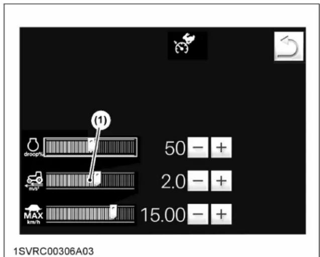
(1) CVT response setting
NOTE :
- Details regarding relevant settings can be found in a different section.
(See Modifying the CVT response setting on page 86.)
6. Cruise control
The traveling speed may be flexibly preset with the ez-command center.
To keep the traveling speed at a constant level, however, make the cruise control setting.
The cruise control can be preset in 4 different conditions for high range speed and low range speed as well as for forward and reverse respectively. The respective preset speed value is memorized when the
cruise control is activated once. Thus, the set speed is not memorized if there is no record for cruise activating. Set the cruise control to "ON", and "CRUISE" and "Cruise preset speeds" appear in the LCD indicator on the instrument panel.
6.1 Setting the cruise control
To set cruise control, use either of the following procedures:
Setting with the ez-command center
- Push the ez-command center forward until a desired traveling speed is reached.
- Hold down the cruise button (for 3 seconds), and the cruise control is enabled. The current speed is recorded as cruise speed, and the machine runs at this speed.
- When moving the ez-command center forward or backward while the cruise control is enabled, the setting speed can be changed. The lowest possible speed change is 0.04 km/h (0.02 mph).

(1) Ez-command center
(2) Cruise button
Calling the memory speed
A single touch on the cruise button while in motion makes the machine run at the previously set cruise speed.
Hold down the cruise button, and the current speed is recorded as cruise speed.
Setting the traveling speed with the foot throttle
- Step on the foot throttle until a desired traveling speed is reached.
- Hold down the cruise button (for 3 seconds), and the cruise control is enabled. The current speed is recorded as cruise speed. The machine runs at this speed.

(1) Display during cruise "ON"
(2) Cruise preset speeds
6.2 Clearing the cruise control
The cruise control can be cleared in any of the following actions:
- Step fully on both the brake pedals.
- Step on one brake pedal with more than 14 km/h (8.7 mph) traveling speed.
- Press the cruise button.
- Set the shuttle lever to neutral.
NOTE :
- The memory value will not be deleted whichever method you use to clear cruise control. Even if you turn the key switch off, the memory value remains.
- Press the cruise button again while running, and the cruise control turns on. The machine can be run at the preset traveling speed.
- Even during cruising, the foot throttle can be used to speed up. Release the pedal, and the previous cruise speed is resumed.
- When the cruise control is activated in the state as which speed is not memorized, the tractor will stay at creep speed (approximately 0.5 km/h / 0.3 mph).
• To activate the cruise control while driving, the tractor speed requires more than 10% of preset speed.
For example, if the preset speed is 40 km/h (24.9 mph), more than 4 km/h (2.5 mph) driving speed is required to activate the cruise control.
7. Ratio lock button
If a large trailer or the like is being towed and the foot throttle is suddenly released to stop the machine on a steep decline, a sudden transmission shift-down slows down the tractor abruptly. As a result, the tractor is pushed by the reaction force of the trailer. In some cases, the tractor may go temporarily out of control.
To prevent such unexpected situations, take the following steps. Press the ratio lock button and get the gear shift locked before releasing your foot from the foot throttle. Then slow down the machine to some extent only with the engine brake.
Afterward, release the ratio lock button and step on the brake pedal to stop.

(1) Ratio lock button
8. Limp home switch
If the transmission has trouble, press this switch, and the tractor can be moved for an emergency escape.
- Press the (F) or (R) switch to enter limp home mode.
- In traveling stop status, press the (F) or (R) switch to move at a fixed speed while the switch is held down. The speed will also increase if you step on the foot throttle while traveling.
- When switching traveling directions, press the (F) or (R) switch after coming to a complete stop.
- Step on the clutch pedal to stop.
NOTE :
- Depending on trouble spots, the tractor may fail to run as expected.
- Park it in a safe place and immediately contact your local KUBOTA Dealer.
- If you press the (F) or (R) switch by mistake, turn the key switch off to leave limp home mode.

(1) Limp home switch forward (F)
(2) Limp home switch reverse (R)
STOPPING THE TRACTOR
- Slow down the engine.
- Step on the clutch and brake pedal.
- Wait for the tractor to stop.
- Disengage the PTO.
- Lower the implement to the ground.
- Set the parking brake.
- Shift the transmission to "NEUTRAL".
- Release the clutch pedal.
CHECK DURING DRIVING
IMPORTANT :
Immediately stop the engine if:
• The engine suddenly slows down or accelerates.
- Unusual noises are suddenly heard.
- Exhaust fumes suddenly become very dark.
While driving, check the following items to see that the all parts are functioning normally:
• Engine over-speed limiting indicator on page 163
- Gear shifting warning indicator (Standard, Deluxe, Premium models only) on page 163
- Easy Checker TM on page 164
• Fuel gauge on page 166
• DEF/AdBlue ® gauge on page 166
- Pneumatic pressure gauge (if equipped) on page 166
• Coolant temperature gauge on page 166
• Tachometer on page 167
1. Engine over-speed limiting indicator
The engine over-speed limiting indicator informs the operator of engine over-speed by indicator and warning buzzer.
If the warning sounds, immediately lower the engine rpm with brakes and such. When the engine rpm decreases, the warning will stop.
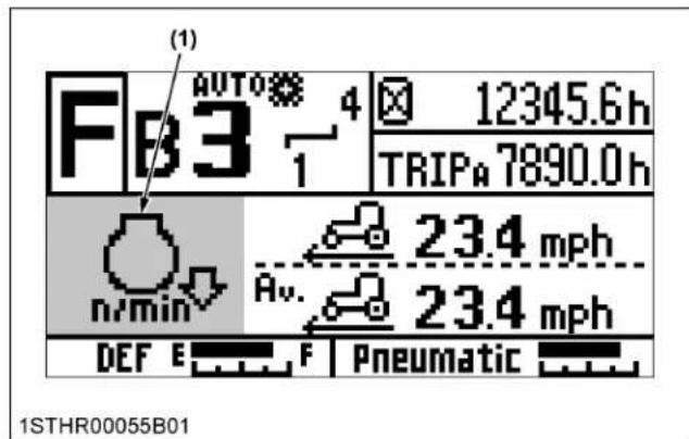
(1) Engine over speed limiting indicator
NOTE :
- Normal operation will not lead to over-speed, but, for instance, if suddenly shifting down when running with a trailer at full speed, the tractor will be pushed by the trailer and may go into over-speed.
2. Gear shifting warning indicator (Standard, Deluxe, Premium models only)
As in the following table, if gear shifting does not operate as desired, the operator will be informed by indicator and warning buzzer.
If the warning sounds, immediately stop the tractor and begin operation again. Upon correct operation, the warning will stop.
| Gear Shifting Measures | |
| When running at high engine rpm in a low-speed gear, range gear was shifted to slow-down, but returned to the original gear without shifting. | 1. Lower the engine rpm and shift down.2. Shift down with the power shift. |
| Range gear was shifted (rev-up or slow-down), but returned to the original gear without shifting.At high rpm, range gear was shifted from B to A in the slow-down direction, but returned to the original gear without shifting. | Lower the engine rpm and shift gears again. |
| When running at D-6 speed with the creep gear “ON”, the gear cannot be shifted to E-1. | Switch the creep gear shift to “OFF”. |
| Range gear was shifted to E with the creep gear “ON”. | |
| When the engine load is within a certain range, attempting to shift the range gear from A to B or from B to A fails. The range gear does not shift and then it returns to the original position. | Disengage the clutch and/or set the shuttle lever to “NEUTRAL” (or press the shuttle neutral button) and then attempt the shift gears again. |
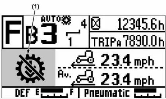
1STHR00055C01
(1) Gear shifting warning indicator
3. Easy Checker TM
If the red indicators on the Easy Checker ™ come on or blink during operation, immediately stop the engine, and find the cause as follows.
If any of the amber indicators light up or start blinking, remove the cause of the trouble as required.
Never operate the tractor while an Easy Checker TM indicator is on.

(1) Easy Checker TM
Engine warning
This indicator serves the following 2 functions. If the warning indicator lights up, pinpoint the cause and take a proper measure.
- Error with the engine control system If during operation the water temperature gauge reads an acceptable level but the warning indicator on the Easy Checker™ comes on, stop the engine and then restart it. If the error happens again, consult your local KUBOTA Dealer.
IMPORTANT :
- If the warning indicator lights up, the following phenomena may appear depending on the engine's trouble spot.
- The engine stops unexpectedly.
- The engine fails to start or gets interrupted just after starting.
- The engine output is not enough.
- The engine output is enough, but the warning indicator stays on.
If the engine output is not enough, immediately interrupt the operation and move the tractor to a safe place and stop the engine.
2. Engine overheat
If the water temperature gauge reads an unusual level and the indicator on the Easy Checker ™ comes on, the engine may have overheated.
Check the tractor by regarding the troubleshooting section of this manual.
(See TROUBLESHOOTING on page 286.)
Engine oil pressure
If the oil pressure in the engine goes below the prescribed level, the warning indicator on the Easy Checker ™ will light up.
If this should happen during operation, and it does not go off when the engine is accelerated to more than 1000 rpm, check the engine oil level.
(See Checking engine oil level on page 241.)

Emission indicator
If this indicator lights up, take the steps to lower the water temperature. This helps keep the emission clean.

Electrical charge
If the alternator is not charging the battery, the warning indicator on the Easy Checker ™ will light up.
If this should happen during operation, check the electrical charging system or consult your local KUBOTA Dealer.

Master system warning
If trouble should occur at the engine, transmission, hydraulic or other control parts, the indicator flashes and the warning buzzer whistles as a warning.
The “Master system warning” indicates more severe trouble than the “System abnormality”. If the trouble is not corrected by restarting the tractor, consult your local KUBOTA Dealer.

System abnormality
If trouble should occur at the engine, transmission, hydraulic or other control parts, the indicator flashes and the warning buzzer whistles as a warning.
Move the tractor to a safe place and stop the engine.
If the trouble is not corrected by restarting the tractor, consult your local KUBOTA Dealer.

Parking brake
If the parking brake is applied, the warning indicator on the Easy Checker TM will light up.
If the indicator is on during operation, release the parking brake lever immediately.

Brake oil pressure
If a fault occurs in the tractor braking system, the warning indicator in the Easy Checker ™ will light up.
If this should happen during operation, stop the engine and consult your local KUBOTA Dealer.

Trailer brake warning
If the trailer brake has some trouble, the warning indicator on the Easy Checker TM will light up.
If this should happen during operation, check the hydraulic or pneumatic brake system or consult your local KUBOTA Dealer.

DEF/AdBlue® system warning
If trouble should occur at the DEF/AdBlue ® system, the warning indicator on the Easy Checker ™ will light up.
If this should happen during operation, check the DEF/AdBlue ® system or consult your local KUBOTA Dealer.

Fuel level
If the fuel in the tank goes below the prescribed level, the indicator on the Easy Checker ™ will light up (less than 62 L / 16.4 U.S.gals.).
If this should happen during operation, refuel as soon as possible.
(See Checking and refueling on page 238.)
IMPORTANT :
- When the fuel indicator lights up, refuel the tank as soon as possible. If the tractor runs out of fuel and stalls, the engine and its components may be damaged.

Water separator
If water or impurities collect in the water separator, the indicator will be displayed on the LCD monitor and the buzzer will sound.
If this should happen during operation, drain the water from the water separator as soon as possible. (See Checking water separator on page 240.)

DEF/AdBlue® level
If the DEF/AdBlue ® in the tank goes below the prescribed level, or if a poor-quality product is added, the indicator in the Easy Checker ™ will light up.
If this should happen during operation, refill or replace with DEF/AdBlue ® as soon as possible.
(See SELECTIVE CATALYTIC REDUCTION (SCR) MUFFLER on page 116.)

Air cleaner
If the air cleaner is clogged, the indicator will be displayed on the LCD monitor.
If this should happen during operation, clean the air cleaner element.
(See Cleaning air cleaner primary element on page 250.)

Hydraulic suction oil filter
If the hydraulic suction oil filter (Suction side or Return side) is clogged, the indicator on the Easy Checker ™ will light up.
If this should happen during operation, replace the hydraulic suction oil filter.
(See Replacing hydraulic oil filter (suction) on page 262 and Replacing hydraulic oil filter (return) on page 264.)

Transmission oil filter
If the transmission oil filter is clogged, the indicator on the Easy Checker TM will light up.
If this should happen during operation, replace the transmission oil filter.
(See Replacing transmission oil filter on page 270.)

Steering oil filter
If the steering oil filter is clogged, the indicator on the Easy Checker TM will light up.
If this should happen during operation, replace the steering oil filter.
(See Replacing power steering oil filter on page 264.)
NOTE :
- For checking and servicing of your tractor, consult your local KUBOTA Dealer for instructions.
4. Fuel gauge
The needle indicates the amount of fuel left regardless of the key position.
Be careful not to empty the fuel tank. Otherwise air may enter the fuel system. Should this happen, the system should be bled.
(See Bleeding fuel system on page 277.)

(1) Fuel gauge (A) "FULL"
(B) "EMPTY"
5. DEF/AdBlue ® gauge
The DEF/AdBlue ® level in the DEF/AdBlue ® tank is indicated with LCD blocks.
If DEF/AdBlue ® level drops too low, the engine output is restricted. With this in mind, be careful not to empty the tank.
When the fluid level in the tank has dropped below 40%, the DEF/AdBlue ® warning indicator and the low-level icon of DEF/AdBlue ® on the instrument panel light up and stay on.
To maintain tractor performance, it is recommended to add DEF/AdBlue ® to the specified level quickly.

(1) DEF/AdBlue ® gauge
(A) "FULL"
(2) DEF/AdBlue ® warning indicator
(B) "EMPTY"
(3) Low-level icon of DEF/AdBI-ue®
6. Pneumatic pressure gauge (if equipped)
The gauge's LCD blocks show the pneumatic pressure in the trailer brake air tank.
If the pneumatic pressure has dropped too low, the trailer brake warning indicator on the instrument panel lights up and stays on.
Do not run the tractor until the air tank is charged with air and the pneumatic pressure gauge is extended to the right.

(1) Pneumatic pressure gauge
(A) "Prescript pressure"
(2) Trailer brake warning indicator
(B) "Low pressure"
7. Coolant temperature gauge

WARNING
To avoid personal injury or death:
- Do not remove the radiator cap until coolant temperature is well below its boiling point. Then, loosen the cap slightly to the first stop to relieve any pressure before removing the cap completely.
- With the key switch at "ON", this gauge indicates the temperature of the coolant. [C] is for cold and [H] is for hot.
- If the indicator reaches the red zone position, the engine coolant is overheated. Check the tractor by reading the troubleshooting section of this manual. (See TROUBLESHOOTING on page 286.)

(1) Coolant temperature gauge (A) "RED ZONE"
8. Tachometer
The tachometer indicates the engine speed on the dial.
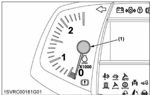
(1) Engine revolution
HEADLAND MANAGEMENT SYSTEM

WARNING
To avoid personal injury or death:
- Never utilize the headland management system, if anyone is in the work area of the tractor.
System description
Depending on different types of crops and working methods, your headland may require different operation.
Once such procedures are preprogrammed, the operator can run the machine on headland in a simple way for better productivity and less operator fatigue.
For instance, let's preprogram the operating procedure on headland as shown in the following table.
- Press the field-out button when you reach the headland, and the steps (1) through (4) are carried on in sequence.
- After turning the machine, press the field-in button, and the steps (5) through (8) are carried on in sequence.
| Operating example on headland | ||
| Field out | Field in | |
| (1) Implement "UP"(2) PTO "OFF"(3) Differential lock "OFF"(4) 4WD "OFF" | (5) 4WD "ON"(6) Differential lock "ON"(7) PTO "ON"(8) Implement "DOWN" | |
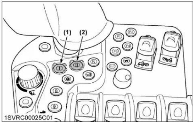
(1) Field out button
(2) Field in button

flowchart
graph TD
    A["Tractor A"] -->|5| B["Tractor B"]
    B -->|3| C["Tractor C"]
    C -->|4| D["Tractor D"]
    D -->|6| E["Tractor E"]
    E -->|7| F["Tractor F"]
    F -->|8| G["Tractor G"]
    style A fill:#f9f,stroke:#333
    style B fill:#f9f,stroke:#333
    style C fill:#f9f,stroke:#333
    style D fill:#f9f,stroke:#333
    style E fill:#f9f,stroke:#333
    style F fill:#f9f,stroke:#333
    style G fill:#f9f,stroke:#333
(A) "FIELD IN"
(B) "FIELD OUT"
1. Programming the headland management system
To utilize the headland management system, it must be preprogrammed.
Details regarding the initial entries and modifications for the program can be found in a different section.
(See Setting the headland management system on page 88.)
2. Loading a program to the program code
By selecting 2 types of programs that are frequently used within a loaded program and loading to the program codes (I, II', I'), the programs can be executed simply by touching the field out button or field in button.
For details on loading a program to a program code, refer to the section Setting the headland management system on page 88.

1SVRC00313B01
(1) Program codes
(2) Work name and implement name entered when the program was loaded
3. Handling the headland management system
- Get the engine started and touch the right half of the headland management system lock and unlock switch to unlock the system. Once unlocked, the headland management system lock indicator goes off.
- Using the program select switch, choose the program code (I or I').
-
When the headland has been reached, press the field out button. The recorded program will be carried on. After swiveling the machine, press the field in button.
-
To interrupt the program execution, press the field out or field in button, for which the indicator stays on.

flowchart
graph TD
    A["(1)"] --> B["Step 1"]
    B --> C["(2)"]
    C --> D["Step 2"]
    D --> E["(3)"]
    E --> F["Preview Icon"]
    G["(4)"] --> H["I→II"]
    I["5.0"] --> J["Arrow to Start"]
    K["3"] --> L["Arrow to End"]
1SVRC00308A01
(1) Headland management system lock indicator
(2) Program code display indicator
(3) Headland management system lock and unlock switch
(4) Program select switch
NOTE :
- The headland management system is kept locked all the time when the engine gets started. To enable this system, press the headland management system lock and unlock switch to unlock it.
- While the program is being executed, the manually operated levers and switches can be used. If the opposite operation takes place while the program is running, however, the program run is interrupted.
For example, the program is interrupted if the 3-point quick lower switch is used and then the 3-point quick raise switch is pressed.
- Before turning on the PTO shaft, use the PTO gear shift lever to select the PTO shaft speed (540 or 1000 rpm) in advance.
- Before using the remote control valves, set the remote control valve switch to the "NEUTRAL" position.
- Work can also be started, pressing the field in button as the first step.
Field in and out buttons
When the indicators of both buttons are on, press either of the buttons to activate the headland management system.
| With the headland management system lock/unlock switch at lock position | Indicators of both buttons: "OFF" |
| With the headland management system program ready to run | Indicators of both buttons: "ON" |
| With the field out button pressed and the program running | Indicator of field out button: "ON"Indicator of field in button: "OFF" |

(1) Field out button
(2) Field in button
(3) Indicator
FRONT SUSPENSION (IF EQUIPPED)

WARNING
To avoid personal injury or death:
- The front suspension control system is working when the engine is running. In the AUTO mode, the control system will subtly change the machine's height at startup or as weight changes when implements are attached. These subtle movements can be unexpected. Before starting it, make sure the area near the machine is clear of all persons and objects.
The front suspension system works to absorb shocks and vibrations that can be caused by field surface
conditions, road surface conditions, and changes in weight caused by implements. Different implements can change the way a tractor carries weight and that weight is also changed when driving in the field or driving on the road. The front suspension system provides the operator with a smoother ride, improved tractor stability, and higher productivity. The front suspension control system has two control switches that allow the operator to adjust the suspension system to operating conditions. Those switches are the auto and block mode selection switch and the suspension manual control switch. The operator can quickly adjust the suspension system to changing conditions with a touch of the switches.

(1) Suspension cylinder
1. Front suspension modes
Choose the front suspension status from the following modes.
- Auto mode:
The front suspension functions in the entire speed range of the tractor.
This mode is recommended for general work.
- Block mode:
Under 40 km/h (25 mph) or so, the suspension cylinder is retracted and fixed at its lowest position. When the tractor speed rises above 40 km/h (25 mph), this mode is automatically switched to the auto mode.
This mode is recommended for work with a front loader or similar implements.
- Manual mode:
The suspension cylinder can be manually extended and retracted to readjust the tractor height.
When the tractor speed rises above 2 km/h (1 mph) or so, this mode is automatically switched to the auto mode.
This mode is recommended for attaching and detaching implements, inspecting the tractor, and so on.
2. Switching of the modes
For Standard, Deluxe models:
- Press the top half of the mode selection switch, and the auto mode is selected. Pressing its bottom half enables the block mode.
- Press the top half of the manual switch in the auto mode to select manual lowering mode. Manual raising mode can be selected by pressing the bottom half.

(1) Front suspension mode selection switch
(2) Front suspension manual switch
(A) Auto mode
(B) Block mode
(C) "DOWN"
(D) "UP"
For Premium, Premium KVT models:
- On the K-monitor screen, select the auto or block mode.
Details regarding the setting procedure can be found in a different section.
(See Setting the drivability on page 77.)

(1) Suspension (active indicator)
(2) Suspension (auto indicator)
(3) Front suspension (block) switch
(4) Front suspension (auto) switch
(5) Front suspension level meter
How to read the indicator:
| Auto indicator | Active indicator | |
| Auto mode | ON | OFF |
| Block mode | OFF | OFF |
| Manual mode | OFF | ON |
- Press the top half of the manual switch in the auto mode to select manual lowering mode. Manual raising mode can be selected by pressing the bottom half.
The tractor height in the manual mode can also be checked with the level meter.

(1) Front suspension manual switch
(A) "DOWN"
(B) "UP"
3. How to read the suspension indicator
The mode selector switch status can be checked with the indicator on the instrument panel.

(1) Suspension indicator
| Suspension indicator | |
| Auto mode ON | |
| Block mode OFF | |
| Manual mode Blinking |
4. Traveling speed and modes
The auto, block and manual modes are automatically switched, as shown in the following table, according to the traveling speed.
| Mode selection switch | Manual switch | Traveling speed | ||
| Below 2 km/h (1 mph) | Below 40 km/h (25 mph) | Above 40 km/h (25 mph) | ||
| Auto mode selected | OFF Auto mode | |||
| ON | Manual mode (manual switch enabled)*1 | Auto mode | ||
| Block mode selected | OFF | Block mode Auto mode | ||
| ON | ||||
*1 The manual switch is disabled during deceleration.
NOTE :
- When restarting the engine while driving in automatic mode, the mode may remain in automatic or switch to manual, depending on the suspension cylinder stop position. If the traveling speed is 2 km/h (1 mph) or higher, it will switch to automatic mode.
PARKING THE TRACTOR
WARNING
To avoid personal injury or death:
Before dismounting tractor
• Always set parking brake and lower all implements to the ground.
Leaving the transmission in gear with the engine stopped will not prevent the tractor from accidental rolling.
- Stop the engine and remove the key.
- Before getting off the tractor, disengage the PTO, lower all implements, place all control levers in their neutral positions, pull the parking brake lever up to park, stop the engine and remove the key.
- If it is necessary to park on an incline, be sure to chock the wheels to prevent accidental rolling of the machine.
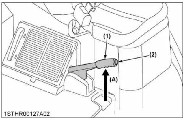
(1) Parking brake lever
(A) "PULL"
(2) Release button
IMPORTANT :
- Do not leave your tractor in the rain. If it cannot be avoided, cover the muffler pipe to prevent water entering.
NOTE :
• After stopping the machine, be sure to apply the parking brake.
When the key switch is turned off with no parking brake applied, the warning buzzer sounds for around 10 seconds.
- Once the parking brake has been applied, the machine sets itself in the 4-wheel drive mode. This helps the 4 wheels to increase their gripping force on slopes.
1. Trailer operation
When towing a trailer with dual-line trailer brake (pneumatic), brakes are applied to both tractor and trailer wheels when the parking brake is set to "ON".
However, be aware that with single-line trailer brake (hydraulic) specifications, the parking brake will not be applied to the trailer wheels.
(See Trailer brake on page 140.)
OPERATING TECHNIQUES
1. Operating the tractor on a road

WARNING
To avoid personal injury or death:
- To help assure straight line stops when driving at transport speeds, lock the brake pedals together. Uneven braking at road speeds could cause the tractor to roll-over.
- When traveling on the road with a 3-point hitch mounted implement attached, be sure to have sufficient front weight on the tractor to maintain steering ability.
- When traveling on the road with or without a trailer, you must comply with local regulations at all time.
The maximum traveling speed with trailer is determined by each country, and regulated speeds may vary according to the size of the trailer and the type of trailer brake system.
Be sure SMV emblem and warning lamps are clean and visible. If towed or rear-mounted equipment obstructs these safety devices, install SMV emblem and warning lamps on equipment.
Consult your local KUBOTA Dealer for further details.
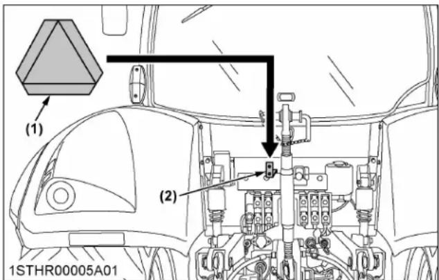
(1) SMV emblem
(2) Bracket
2. Operating on slopes and rough terrain

WARNING
To avoid personal injury or death:
• Always back up when going up a steep slope. Driving forward could cause the tractor to tip
over backward. Stay off hills and slopes too steep for safe operation.
- Avoid changing gears when climbing or descending a slope.
- If operating on a slope, never disengage the clutch or shift levers to "NEUTRAL". Doing so could cause loss of control.
-
Do not drive the tractor close to the edges of ditches or banks which may collapse under the weight of the tractor, especially when the ground is loose or wet.
-
Be sure wheel tread is adjusted to provide maximum stability. (See WHEEL ADJUSTMENT on page 211.)
- Slow down for slopes, rough ground, and sharp turns, especially when transporting heavy, rear-mounted equipment.
- Before descending a slope, shift to a gear low enough to control the speed without using brakes.
3. Transporting the tractor safely
- The tractor, if damaged, must be carried on a truck.
-
Secure the tractor with chains or straps sized appropriately. Make sure all loading ramps are properly sized. Make sure all local tie-down requirements are met.
-
Follow the instructions below when towing the tractor. Otherwise, the tractor's powertrain may be damaged.
-
Set all the shift levers to "NEUTRAL" position.
- If possible, start the engine and select 2WD; if creep speed is fitted ensure that it is disengaged.
- Tow the tractor using its bolt coupling (1) located at front bumper or front 3-point hitch.
- Never tow faster than 10 km/h (6.2 mph).

natural_image
Technical line drawing of a tractor's wheel and tracks assembly (no text or symbols)(1) Bolt coupling

(1) Bolt coupling
- The power steering mechanism makes the steering easier. Be careful when driving on the road at high speeds.
4. Directions for the use of power steering
- Power steering is activated only while the engine is running. Slow engine speeds make the steering a little heavier. While the engine is stopped, tractors with power steering function in the same manner as tractors without power steering.
- When the steering wheel is turned all the way to the stop, the relief valve is activated. Do not hold the steering wheel in this position for a long period of time.
- Avoid turning the steering wheel while the tractor is stopped, or tires may wear out sooner.
PTO
REAR PTO OPERATION

WARNING
To avoid personal injury or death:
- Disengage PTO, stop engine, and allow all rotating components to come to a complete stop before connecting, disconnecting, adjusting, or cleaning any PTO driven equipment.
1. PTO clutch control switch
The PTO clutch control switch engages or disengages the PTO clutch which gives the PTO independent control.
- Pull up the switch knob and tilt it forward, and the PTO clutch comes "ON" (engage).
- Tilt the switch knob backward, and the PTO clutch comes "OFF" (disengage).

(1) Rear PTO clutch control switch
(A) "ON"
(B) "OFF"

(1) Rear PTO clutch control switch
(A) "ON"
(B) "OFF"
IMPORTANT :
- To avoid shock loads to the PTO, reduce engine speed when engaging the PTO, then open the throttle to the recommended speed.
NOTE :
- If the tractor is traveling with the PTO running, standing up from the operator's seat will set off the warning buzzer (the PTO will continue rotating).
- If the tractor is stopped with the PTO running, standing up from the operator's seat will stop the PTO after 1 second (the warning buzzer will sound 1 second after stopping the PTO).
- The PTO clutch can be engaged when the operator is seated in the operator's seat. Otherwise, the clutch cannot be engaged.
- When a high load on the PTO clutch is detected, the PTO clutch control switch "ON" operation (PTO startup) will be restricted after being turned "ON" and "OFF" repeatedly more than 5 times. PTO startup will be possible again 5 minutes after the restriction takes effect.
1.1 PTO clutch indicator
The PTO clutch indicator turns on while PTO clutch is engaged.
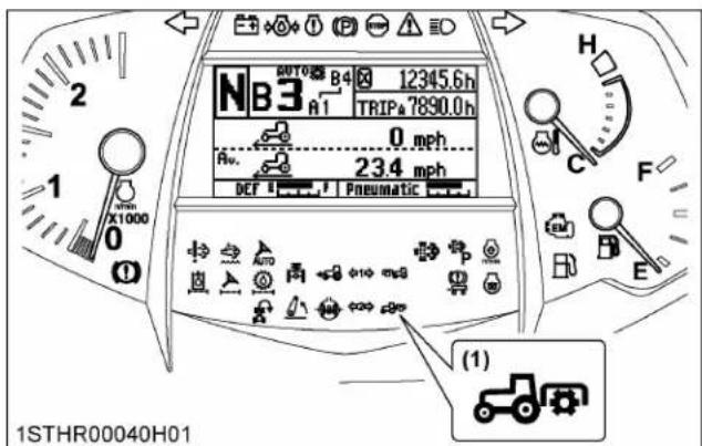
(1) Rear PTO clutch indicator
1.2 PTO rpm display
The rear PTO rpm and front PTO rpm can be displayed on the LCD screen in the instrument panel.

(1) Rear PTO rpm
(2) Front PTO rpm
2. External switch for rear PTO
- Make sure the parking brake is applied.
-
Press the external PTO clutch control "ON" switch and the rear PTO starts turning.
-
If you release the switch within 3 seconds, the PTO stops turning.
-
Hold down the switch for more the 3 seconds and the PTO will keep on turning. Once in continuous rotation mode, the warning buzzer sounds for about 10 seconds. (If the seat switch is on, the warning buzzer will not sounds.)
-
Press the "OFF" switch, and the PTO stops turning. While the rear PTO is turning, the rear PTO indicator on the instrument panel stays on.

(1) External switch for rear PTO "ON"
(2) External switch for rear PTO "OFF"
3. PTO operating mode selector lever and PTO gear shift lever

WARNING
To avoid personal injury or death:
- Be sure to observe the PTO shaft speed prescribed for the individual implements. It is extremely dangerous to run an implement at high speed that is meant to be operated at low speed. Use only when this higher rpm is specifically recommended by the implement manufacturer.
Choose from the following 4 PTO operating modes according to the type of implement or the workload.
- Set the mode selector lever to the "NORMAL" mode for general work and the "ECONOMY" mode for light-duty work only. In the "ECONOMY" mode, the engine runs at low speed, 540 or 1000 rpm, for energy-saving operation.
- Using the PTO gear shift lever, select a speed to suit the implement in use.
| PTO operating mode selector lever | PTO gear shift lever | |
| C | D | |
| Normal(PTO and engine speed) | 540/2005 | 1000/1995 |
| Economy(PTO and engine speed) | 540E/1608 | 1000E/1600 |
Handling the levers
- Before handling both the levers, set the PTO clutch control switch to the "OFF" (disengage) position.
- To shift, hold down the shift lever and move it to the desired position. If the lever is not pushed down, it remains locked and no gear shift can be made.
- When returning the lever to the "NEUTRAL" position, there is no need to push it down.
Standard, Deluxe models

(1) PTO gear shift lever
(A) Normal mode
(2) PTO operating mode selector lever
(B) Economy mode
(C) 540/540E rpm
(D) 1000/1000E rpm
(N) Neutral position
Premium, Premium KVTmodels

(1) PTO gear shift lever
(A) Normal mode
(2) PTO operating mode selector lever
(B) Economy mode
(C) 540/540E rpm
(D) 1000/1000E rpm
(N) Neutral position
IMPORTANT :
- For maximum PTO shaft speeds of various implements, see the implement operator's manual.
NOTE :
- When using the high-speed (1000/1000E) PTO, replace with the included 1000-rpm PTO shaft. When accelerating the engine with the 6-spline 540-rpm PTO shaft installed, PTO rotation will automatically stop when the PTO reaches approx. 650 rpm.
4. 1000 rpm PTO shaft

WARNING
To avoid personal injury or death:
- Be sure to observe the PTO shaft speed prescribed for the individual implements. It is extremely dangerous to run an implement at high speed that is meant to be operated at low speed. Use only when this higher rpm is specifically recommended by the implement manufacturer.
By interchanging the PTO shafts, 2 different PTO shaft speeds can be obtained.

(1) PTO shaft
(A) 540 rpm PTO shaft
(2) Bolt
(B) 1000 rpm PTO shaft
PTO shaft interchanging procedure
The 6-spline 540 rpm PTO shaft is standard equipment.
- Shifting the 2 PTO levers to an arbitrary position, lock the PTO shaft to keep it from rotating.
- Remove the PTO mounting bolts and then remove the PTO shaft.
- After cleaning the PTO shaft mounting surface, mount the 1000-rpm PTO shaft.
Tightening torque: 115 N·m (11.7 kgf·m) (84.8 ft·lbs)
- Set the distance from drawbar pin hole to the rear end of PTO shaft according to the following instructions.
IMPORTANT :
- For maximum PTO shaft speeds of various implements, see the implement operator's manual.
- Implements may be driven at 540 rpm only if their power input never exceeds 60 kW (82 HP).
- Short position hole (Hole A) should never be used for PTO-driven implement.
| Drawbar hole | PTO shaft |
| Hole A | Do not use for PTO-driven implement |
| Hole B | 6 spline for 540 rpm |
| Hole C | 21 spline for 1000 rpm |

(1) Drawbar (A) "Hole A"
(B) "Hole B"
(C) "Hole C"
(D) "DISTANCE"
NOTE :
- When using the high-speed (1000/1000E) PTO, replace with the included 1000-rpm PTO shaft.
With a 6-spline (540 rpm) shaft mounted, if the engine rpm is raised:
"Power Shift model"
The PTO will automatically stop rotating when its rpm reaches roughly 650.
"CVT model"
The PTO rpm will automatically decrease to roughly 630 when it reaches roughly 650.
- When the engine is in overspeed due to external factors, the PTO rotation may stop temporarily.
5. PTO shaft cover and shaft cap

WARNING
To avoid personal injury or death:
- Keep the rear PTO shaft cover in place at all times. Put back the PTO shaft cap when the PTO is not in use.
Before connecting or disconnecting a drive shaft to PTO shaft, be sure engine is "OFF". Raise up the PTO shaft cover. Afterward be sure to return the PTO shaft cover to the "NORMAL POSITION".

(1) PTO shaft cover
(2) PTO shaft cap
(B) "RAISED POSITION"
(A) "NORMAL POSITION"
IMPORTANT :
- The universal joint of the PTO drive shaft is technically limited in its moving angle. Refer to the PTO drive shaft instructions for proper use.
6. Auto PTO operation (Premium and Premium KVT models)
The rear-PTO can be preset to turn itself on and off, being interlocked with the lifting height of 3-point hitch mounted implement.

WARNING
To avoid personal injury or death:
- Use caution when setting auto engagement, considering type of implement in use.
Setting
-
Touch the left half of the auto PTO switch (6), and the setting is enabled. By touching the right half of the switch, and the setting is disabled. While the auto PTO switch (6) is on, the auto PTO indicator (11) also lights up.
-
Use the plus and minus switches (7 and 8) to readjust the height for turning on the PTO in lowering the implement and the height for turning it off in raising the implement.
(See Setting the PTO on page 79.)
NOTE :
- When PTO turning has been stopped by the auto PTO function, the PTO indicator on the instrument panel blinks and the buzzer keeps sounding.
The PTO starts turning by lowering the implement with the 3-point quick lower switch or depth control dial (hydraulic dial).

flowchart
graph TD
    A["1"] --> B["0 min"]
    C["2"] --> D["0 min"]
    E["3"] --> F["0 min"]
    G["4"] --> H["0 min"]
    I["5"] --> J["46%"]
    K["6"] --> L["STOP"]
    M["7"] --> N["STOP"]
    O["8"] --> P["STOP"]
    Q["9"] --> R["STOP"]
    S["10"] --> T["STOP"]
    U["11"] --> V["AUTO"]
    W["-"] --> X["+"]
    Y["+"] --> Z["STOP"]
    style A fill:#f9f,stroke:#333
    style C fill:#f9f,stroke:#333
    style E fill:#f9f,stroke:#333
    style G fill:#f9f,stroke:#333
    style I fill:#ccf,stroke:#333
    style K fill:#ccf,stroke:#333
    style M fill:#ccf,stroke:#333
    style Q fill:#ccf,stroke:#333
    style S fill:#ccf,stroke:#333
    style U fill:#ccf,stroke:#333
    style W fill:#ccf,stroke:#333
    style Y fill:#ccf,stroke:#333
    style Z fill:#ccf,stroke:#333
1SVRC00266B01
(1) Front PTO indicator
(2) Front PTO rpm
(3) Rear PTO indicator
(4) Rear PTO rpm
(5) Height to turn on the PTO in lowering the implement
(6) Auto PTO switch
(7) Plus (+) switch
(8) Minus (-) switch
(9) Height to turn off the PTO in raising the implement
(10) Current lift arm height
(11) Auto PTO indicator
FRONT PTO OPERATION (IF EQUIPPED)
The front PTO and rear PTO are independent, and both PTOs can be operated together or individually.

WARNING
To avoid personal injury or death:
- Disengage PTO, stop engine, and allow all rotating components to come to a complete stop before connecting, disconnecting, adjusting, or cleaning any PTO driven equipment.
- When the front PTO is not used, keep it off.
| Direction of turning PTO | Counter-clockwise, viewed from tractor front |
| PTO/engine speed 1000/2000 rpm | |
| PTO shaft 21 splines |
1. PTO clutch control switch
The PTO clutch control switch engages or disengages the PTO clutch which gives the PTO independent control.
- Pull up the switch knob and tilt it forward, and the PTO clutch comes "ON" (engage).
- Tilt the switch knob backward, and the PTO clutch comes "OFF" (disengage).

(1) Front PTO clutch control switch
(A) "ON"
(B) "OFF"

(1) Front PTO clutch control switch
(A) "ON"
(B) "OFF"
IMPORTANT :
- To avoid shock loads to the PTO, reduce engine speed when engaging the PTO, then open the throttle to the recommended speed.
NOTE :
- If the tractor is traveling with the PTO running, standing up from the operator's seat will set off the warning buzzer (the PTO will continue rotating).
- If the tractor stopped with the PTO running, standing up from the operator's seat will stop the PTO after 1 second.
- The PTO clutch can be engaged when the operator is seated in the operator's seat. Otherwise, the clutch cannot be engaged.
1.1 PTO clutch indicator
The PTO clutch indicator turns on while PTO clutch control switch is in "ON" (engage) position.
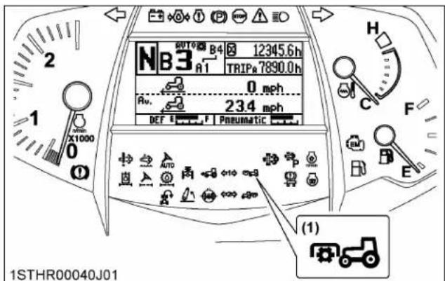
(1) PTO clutch indicator
1.2 PTO rpm display
The front PTO rpm and rear PTO rpm can be displayed in the LCD screen on the instrument panel.

(1) Front PTO rpm
(2) Rear PTO rpm
For Premium, Premium KVT models only:
The front PTO rpm and rear PTO rpm can be displayed on the K-monitor screen.
(See Setting the PTO on page 79.)

(1) Front PTO indicator
(2) Front PTO rpm
(3) Rear PTO indicator
(4) Rear PTO rpm
2. PTO shaft cover and shaft cap

WARNING
To avoid personal injury or death:
- Keep the front PTO shaft cover in place at all times. Put back the PTO shaft cap when the PTO is not in use. Before connecting or disconnecting a drive shaft to PTO shaft, be sure engine is "OFF".

(1) PTO shaft cover
(2) PTO shaft cap
IMPORTANT :
- The universal joint of the PTO drive shaft is technically limited in its moving angle. Refer to the PTO drive shaft instructions for proper use.
3-POINT HITCH AND DRAWBAR

1STHR00005B01
(1) Top link
(2) Lifting rod (left)
(3) Stabilizer
(4) Lower link
(5) Lifting rod (right)
(6) Drawbar
(7) Sway limitation plate
THE 3-POINT HITCH SETUP
-
Make preparations for attaching implement.
-
Adjusting lateral float on page 183
- Selecting the top link mounting holes on page 183
-
Drawbar on page 184
-
Attaching and detaching implements

WARNING
To avoid personal injury or death:
- Be sure to stop the engine.
- Do not stand between the tractor and implement unless the parking brake is applied.
- Before attaching or detaching the implement, locate the tractor and implement on a firm level surface.
- Whenever an implement or other attachment is connected to the tractor 3-point hitch, check the full range of operation for interference, binding or PTO separation.
-
Do not exceed the maximum allowable length of either lifting rod, or the lifting rod will come apart and the 3-point equipment may fall.
-
Remote hitch "UP" switch and "DOWN" switch on page 184
• Lifting rod on page 184 - Top link on page 185
• Stabilizer on page 185 - Sway limitation plate on page 185
- Telescopic lower links on page 186
1. Adjusting lateral float
- To allow the implement to follow ground contour, attach the rectangular washers and pin heads in vertical position.
- To hold the implement, reset the rectangular washers and pin heads in horizontal position.
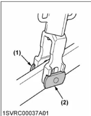
(1) Rectangular washer (2) Pin head

(A) Horizontal position (B) Vertical position
Floating mechanism
When the floating mechanism is used, the implement is able to follow the tractor freely in response to the soil and ground conditions. This is suited for operation with implements wider than the tractor.
Removing the lynch pin

(A) "LOCK" (B) "PUSH"
2. Selecting the top link mounting holes
Select the proper set of holes.
(See Hydraulic control unit use reference chart on page 207.)

(1) Top link
(2) Mounting hole
(3) Handle
3. Drawbar
Remove the drawbar if a close-mounted implement is attached.
4. Remote hitch "UP" switch and "DOWN" switch
These switches provided on both of the rear fenders are used to raise and lower the 3-point hitch for aligning the arm with the implement only.

WARNING
To avoid personal injury or death:
- Do not use the remote hitch "UP" switch and "DOWN" switch when the implement is attached on the 3-point hitch.
Press the "UP" switch and 3-point hitch goes up. Press the "DOWN" switch and the 3-point hitch comes down. Movement of the 3-point hitch stops when the switch is released.

(1) "UP" switch
(2) "DOWN" switch
NOTE :
- If these switches are pushed, the 3-point hitch's position lock is activated and 3-point lifting or lowering indicator starts flashing (2 or so flashes every second). If it flashing, press the 3-point quick raise switch or 3-point quick lower switch to release the position lock (the indicator goes off or turns on).
5. Lifting rod

WARNING
To avoid personal injury or death:
- Do not extend lifting rod beyond the groove on the threaded rod.
- To adjust the length of the lifting rod, lift the adjusting handle and turn to desired length.
- After adjusting, lower the lifting rod adjusting handle to the "LOCK" position.
- When extending the rod using the adjusting handle, do not exceed the groove on the rod thread.

(1) Lifting rod
(2) Adjusting handle
(A) "GROOVE"


(1) Adjusting handle (A) "LOCK POSITION"
(B) "UNLOCK POSITION"
6. Top link

WARNING
To avoid personal injury or death:
- When extending the top link, do not exceed the groove on the top link thread, or the top link will come apart and the 3-point equipment may fall.
- Adjust the angle of the implement to the desired position by shortening or lengthening the top link.
- Then return the lock handle to the "LOCK" position.
- The proper length of the top link varies according to the type of implement being used.

(1) Top link
(A) "LOCK" position
(2) Lock handle
(B) "GROOVE"
7. Stabilizer
The implements can be swung from side to side and get locked by attaching or detaching the lynch pin.
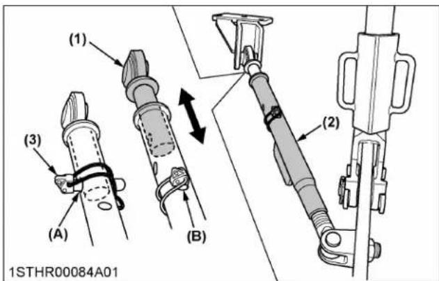
(1) Stabilizer (1)
(A) A hole
(2) Stabilizer (2)
(B) B hole
(3) Lynch pin
To swing the implement from side to side:
Pull the lynch pin out of the stabilizer's hole (A). Turn the stabilizer (2), as required, to readjust the swing range.
(Put the drawn-out lynch pin into the hole (B) in order not to lose it.)
To keep the implement from swinging:
Put the lynch pin into the stabilizer's hole (A). If the hole is out of alignment, turn the stabilizer (2) to realign the hole.
Adjusting the lower link's width
The 3-point hitch of this tractor is of Category 3. (The lower link is 1010 mm (40 in.) wide as a standard.) Do not turn the stabilizer (2) unless otherwise necessary. The lower link's width may get out of spec.
8. Sway limitation plate
When working with an implement for 3-point link (for example plow, disk harrow, and so on.), the sway limitation plate allows the implement to move sideways when the lower link is at the work position (lowered), and regulates its sideways oscillation when lifted while swiveling, so that oscillation adjustment by an existing stabilizer is not required.
As a rule, when mounting an implement for Category 3N, where the matching width is narrow, remove the spacer; when mounting an implement for Category 3, where the matching width is wide, mount the spacer.

(A)
(B)

(1) Sway limitation plate
(A) "CATEGORY 3N"
(2) Spacer
(B) "CATEGORY 3"
(3) Stabilizer
IMPORTANT :
- When regulating sideways oscillation with the sway limitation plate, deactivate oscillation regulation with the stabilizer.
- Raise and lower the implement to check that the lower link does not make contact with the tires.
9. Telescopic lower links
To attach an implement, follow the instructions below:
- Pull the lock pins, pull out the lower link ends, and attach to the implement.
- Back up the tractor slightly to make sure the lower links are pushed in securely.
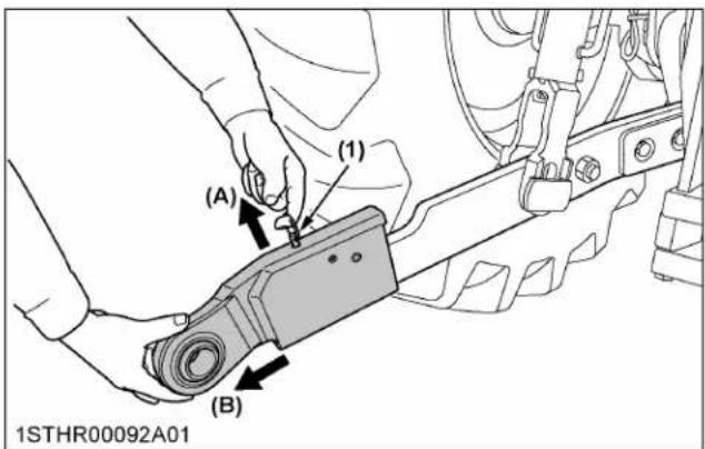
(1) Lock pin (A) "PULL"
(B) "PULL OUT"
DRAWBAR

WARNING
To avoid personal injury or death:
- Never pull from the top link, the rear axle or any point above the drawbar. Doing so could cause the tractor to tip over rearward causing personal injury or death.
1. Adjusting drawbar length
The drawbar can be used in 3 positions.
The drawbar load is specified in the "IMPLEMENT LIMITATIONS" section.
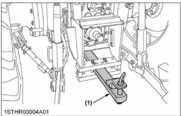

(1) Drawbar
(A) Holes
(2) Pivot pin
(B) Holes
(C) Holes
2. Swing drawbar
The drawbar can be used in 3 different ways as shown in the following illustration. Assemble it correctly with locating pins.

(1) Drawbar
(2) Locating pin
FRONT 3-POINT HITCH (IF EQUIPPED)

WARNING
To avoid personal injury or death:
- It is very dangerous to run the machine at high speed with a front 3-point hitch implement attached. It is strongly recommended to run the machine at a low speed permitting full attention to operation.
- When travelling on public roads, take anti-drop measures for front-mounted implements.
- Do not attach any implement that may block the operator's front vision or the headlight beam.
The hydraulic lifting unit of the front 3-point hitch can be switched for single-acting cylinder or double-acting cylinder. It enables a wide variety of work.
When an implement is attached at the tractor front and another one at the tractor back, the working efficiency can be dramatically improved.
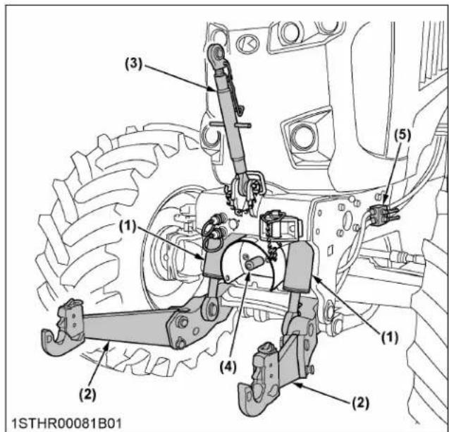
(1) Lift cylinder
(2) Lower link
(3) Top link
(4) PTO
(5) Hydraulic selector valve
1. Lift control
The front 3-point hitch cylinder is connected with the remote control valve.
- Pull the remote control valve lever or switch toward yourself, and the lower link is raised. Push it away from yourself, and the link is lowered.
- Release your hand from the lever or switch, and the lower link returns to its "NEUTRAL" position.
- When you push the lever or switch further from the "LOWER" position, the lower link is fixed at the "FLOAT" position. The implement will be able to follow the terrain.

(1) Front 3-point hitch control lever
(A) "RAISE"
(B) "LOWER"
(C) "NEUTRAL"
(D) "FLOAT"
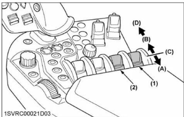
(1) Front 3-point hitch control
switch
(6-gang remote control valves type)
(2) Front 3-point hitch control switch
(5-gang remote control valves type)
(A) "RAISE"
(B) "LOWER"
(C) "NEUTRAL"
(D) "FLOAT"
2. Remote hitch "UP" switch and "DOWN" switch (if equipped)
These switches provided on the front frame are used to raise and lower the front 3-point hitch for aligning the arm with the implement only.

WARNING
To avoid personal injury or death:
- Do not use the remote hitch "UP" switch and "DOWN" switch when the implement is attached on the front 3-point hitch.
Press the "UP" switch and front 3-point hitch goes up. Press the "DOWN" switch and the front 3-point hitch comes down.
Movement of the front 3-point hitch stops when the switch is released.

(1) "UP" switch
(2) "DOWN" switch
3. Switching of the hydraulic valve
Using the 2 selector levers, the hydraulic circuit can be switched to the "single-acting", "double-acting" or "lock" mode.
Switch to the circuit suited for the implement. Incorrect selection may damage the implement.

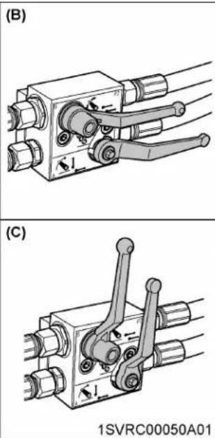
natural_image
Technical line drawings of mechanical components labeled (B) and (C), showing assembly or assembly steps without any readable text or symbols.(1) Selector valve lever 1
(2) Selector valve lever 2
(A) "SINGLE-ACTING"
(B) "DOUBLE-ACTING"
(C) "LOCK"
NOTE :
- For the selector valve lever 1, pull out its turning part outward and turn the lever.
Single-acting:
The lower link is hydraulically raised but lowered by its own weight.
This mode is used for mowers, cultivators and others.
Double-acting:
The lower link is hydraulically raised and lowered.
This mode is used for snow removal with a front blade and other similar applications.
Lock:
The hydraulic circuit to the implement is cut off. This mode is used for traveling on public roads and when the front 3-point hitch is not used.
4. Lower link
The lower link is foldable. Set it correctly according to the relevant work.


(1) Lower link
(2) Lock pin
(A) "GENERAL WORK"
(B) "FLOATING WORK"
(C) "TRANSPORT and STORAGE"
For general works:
Put the pin into the position shown below, and fix the lower link.
For floating works:
When the pin is placed in the position below, the lower link is movable up and down by about 90 mm (3.54 in.).
For transport and storage:
Put the pin into the position shown below, and retract the cylinders completely.
5. Top link
When the top link is not used, fix it with the top link pin.

(1) Top link
(2) Top link pin
HYDRAULIC UNIT
This tractor's hydraulic system is equipped with the following features, to name a few, to meet a wide variety of jobs.
- Load sensing type mix draft control
- Multiple-segment remote hydraulic control valves
- Remote hydraulic control with flow control valve
- Large-capacity external hydraulic power beyond port (Deluxe, Premium, Premium KVT models only)
- Load sensing variable-displacement hydraulic pump (Deluxe, Premium, Premium KVT models only)
IMPORTANT :
- Do not operate until the engine is warmed up. If operation is attempted when the engine is still cold, the hydraulic system may be damaged.
- If noises are heard when implement is lifting after the depth control dial (hydraulic dial) has been activated, the hydraulic mechanism is not adjusted properly. Unless corrected, the unit will be damaged. Contact your KUBOTA Dealer for adjustments.
3-POINT HITCH CONTROL SYSTEM

WARNING
To avoid personal injury or death:
- Before using the 3-point hitch controls, ensure that no person or object is in the area surrounding the implement or 3-point hitch. Do not stand on or near the implement or between the implement and tractor when operating the 3-point hitch controls.
1. Terminology (Standard, Deluxe models)

(1) 3-point quick raise and lower switch
(2) 3-point hitch lock button
(3) Depth control dial (hydraulic dial)
(4) Lift arm top limit adjustment dial
(5) 3-point hitch lowering speed adjustment dial
(6) Draft ratio adjustment dial
(7) Ride control switch
2. Terminology (Premium and Premium KVT models)

(1) 3-point quick raise and lower switch
(2) Depth control dial (hydraulic dial)
(3) 3-point hitch lock button
(4) 3-point hitch lock indicator
(5) 3-point hitch status indicator
(6) Ride control indicator
(7) Auto draft mode indicator
(8) Wheel slip control indicator
(9) 3-point hitch lock switch
(10) Ride control switch
(11) Auto draft mode switch
(12) Wheel slip control switch
(13) Plus (+) switch
(14) Minus (-) switch
(15) Wheel slip control
(16) Draft sensitivity control
(17) 3-point hitch lowering speed control
(18) Lift arm height control
3. 3-point hitch lock button

WARNING
To avoid personal injury or death:
- Before checking 3-point mounted implement, be sure to lock the implement with the lock button. In such case, turn the depth control dial (hydraulic dial) toward down and make sure the implement does not drop.
- Before road traveling, be sure to lock the implement with the 3-point hitch lock button. If traveling with the ride control on, unlock the 3-point hitch lock button.
Each time you press the 3-point hitch lock button, the lock and unlock status switch, and the switch indicator goes on while the lock status is on.
Before traveling on public roads, be sure to get the 3-point hitch locked to avoid accidental drop of the implement.
If traveling with the ride control on, unlock the 3-point hitch lock button.
Standard, Deluxe models
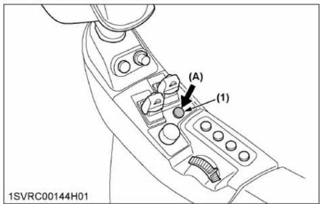
(1) 3-point hitch lock button (A) "PUSH"
Premium, Premium KVT models

(1) 3-point hitch lock button (A) "PUSH"
4. Position and mix draft mode select
Select the position control or the draft control depending on the type of work. Choose the draft control for jobs requiring traction such as plowing and subsoiling.
Standard, Deluxe models
| Mode in use Method | |
| Position control | Turn the dial fully counterclockwise. |
| Mix draft control | Turn the dial farther to the right to increase the percentage of work done in draft control versus that in position control. |

(1) Draft ratio adjustment dial (A) "Position control mode"
(B) "Mix draft mode"
Premium, Premium KVT models
| Mode in use Method | |
| Position control | Move the draft sensitivity slider fully to the left at 0%. |
| Mix draft control | Move the draft sensitivity slider further to the right to increase the percentage of work done in draft control versus that in position control. |
| Auto draft | Touch the left half of the auto draft mode switch, and the auto draft mode is selected and the auto draft mode indicator lights up. In auto draft mode, the percentage of the mix control is automatically adjusted although the value on the monitor does not change. Touch the right half of the auto draft mode switch, and the auto draft mode is canceled. |
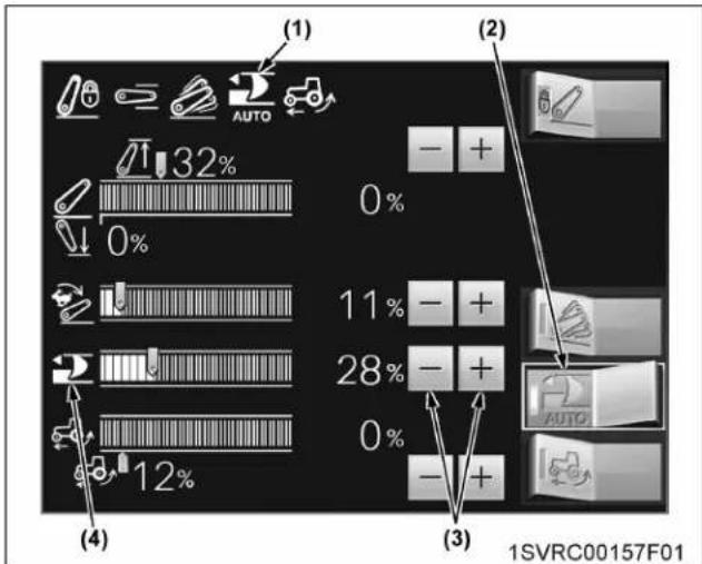
bar
| Category | Value (%) | |---|---| | (1) AUTO | 32 | | (1) | 0 | | (2) AUTO | - | | (2) | + | | (3) AUTO | - | | (3) | + | | (4) | 12 | | (4) | 0 | | (4) | - | | (4) | + | 1SVRC00157F01(1) Auto draft mode indicator
(2) Auto draft mode switch
(3) Draft sensitivity adjustment switch
(4) Draft sensitivity control
NOTE :
- Details regarding the setting procedure can be found in the different section.
(See Setting the 3-point hitch on page 72.)
5. Depth control adjustment dial (hydraulic dial)
- The implement height (plowing depth) can be adjusted.
Details regarding the adjustments can be found in a different section.
(See Position control on page 193, Mix draft control on page 194, and Float control on page 194.)
- For traveling on public roads, keep the implement raised with the dial.
- When the dial is preset for the implement to get to the lower limit, the 3-point quick raise and lower switch can be used to raise and lower the implement.
Standard, Deluxe models

(1) 3-point quick raise and lower switch
(2) Depth control dial (hydraulic dial)
Premium, Premium KVT models

(1) 3-point quick raise and lower switch
(2) Depth control dial (hydraulic dial)
6. Position control
This will control the working depth of the 3-point hitch mounted implement regardless of the amount of pull required.
Standard, Deluxe models

(1) Depth control dial (hydraulic dial)
(A) "FLOAT"
(B) "DOWN"
(C) "UP"
Premium, Premium KVT models

(1) Depth control dial (hydraulic dial)
(A) "FLOAT"
(B) "DOWN"
(C) "UP"
7. Mix draft control
This will control the pull of the 3-point implement.
As the load on the 3-point hitch changes due to various soil conditions, the draft control system automatically responds to these changes by either raising or lowering the implement slightly to maintain a constant pull.
Set the implement pull with the depth control dial (hydraulic dial).
Standard, Deluxe models

(1) Depth control dial (hydraulic dial)
(A) "FLOAT"
(B) "DEEP"
(C) "SHALLOW"
(D) "UP"
Premium, Premium KVT models

(1) Depth control dial (hydraulic dial)
(A) "FLOAT"
(B) "DEEP"
(C) "SHALLOW"
(D) "UP"
Adjusting the draft sensitivity:
During work in the draft mode, readjust the sensitivity with the dial or switch according to the plowing depth, the type of soil and other factors, referring to the following table.
| Draft ratio adjustment dial(Standard, Deluxe models) | Turn the dial counterclockwise. | Turn the dial clockwise. |
| Draft sensitivity adjustment switch(Premium, Premium KVT models) | Retract the bar graph leftward with the (-) switch. | Extend the bar graph rightward with the (+) switch. |
| Plowing depth Shallow | Deep | |
| Type of soil Light Heavy | ||
| Field ruggedness Little | Much | |
| Sensitivity | (Low) | (High) |
8. Float control
Place the depth control dial (hydraulic dial) in the "FLOAT" position (left-most) to make the lower links move freely along with the ground conditions.
9. Lift arm top limit adjustment
Set for work in which a 3-point hitch top limit is required.
For Standard, Deluxe models:
-
Turn the dial in the "HIGH" direction to increase the top limit of the 3-point hitch.
-
Turn the dial in the "LOW" direction to decrease the top limit of the 3-point hitch.

(1) Lift arm top limit adjustment dial
(A) "HIGH"
(B) "LOW"
For Premium, Premium KVT models:
Using the (+) and (-) switches, the setting can be changed (the setting is variable in the 30-100% range).
-
Slide the slider to the right (increasing the value) to raise the top limit of the 3-point hitch.
-
When the setting has reached 100%, the top limit control is turned off.
Details regarding the setting procedure can be found in a different section.
(See Setting the 3-point hitch on page 72.)
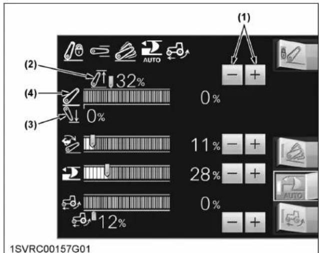
(1) Lift arm top limit adjustment switch
(2) Lift arm top limit control
(3) Lift arm bottom limit control
(4) Lift arm height control, current position (height)
10. 3-point hitch lowering speed adjustment
Adjust to the lowering speed suited for the implement in use.

WARNING
To avoid personal injury or death:
- A fast lowering speed may cause damage or injury. The lowering speed of the implement should be adjusted to 2 or more seconds.
For Standard, Deluxe models:
- Turn the dial in the "FAST" direction, and the 3-point hitch's lowering speed will increase.
- Turn the dial in the "SLOW" direction, and the 3-point hitch's lowering speed will decrease.

(1) 3-point hitch lowering speed adjustment dial
"FAST"
"SLOW"
For Premium, Premium KVT models:
-
Using the (+) and (-) switches, the setting can be changed.
-
The longer the bar graph is extended rightward, the further will the 3-point hitch's lowering speed increase.
• The more the bar graph is shortened leftward, the further will the 3-point hitch's lowering speed decrease.
Details regarding the setting procedure can be found in a different section.
(See Setting the 3-point hitch on page 72.)

bar
| Category | Value (%) | |---|---| | Group 1 | -1 | | Group 2 | +1 | | Group 3 | -1 | | Group 4 | +1 | | Group 5 | -1 | | Group 6 | +1 | | Group 7 | -1 | | Group 8 | +1 | | Group 9 | -1 | | Group 10 | +1 | | Group 11 | -1 | | Group 12 | +1 | | Group 13 | -1 | | Group 14 | +1 | | Group 15 | -1 | | Group 16 | +1 | | Group 17 | -1 | | Group 18 | +1 | | Group 19 | -1 | | Group 20 | +1 | | Group 21 | -1 | | Group 22 | +1 | | Group 23 | -1 | | Group 24 | +1 | | Group 25 | -1 | | Group 26 | +1 | | Group 27 | -1 | | Group 28 | +1 | | Group 29 | -1 | | Group 30 | +1 | | Group 31 | -1 | | Group 32 | +1 | | Group 33 | -1 | | Group 34 | +1 | | Group 35 | -1 | | Group 36 | +1 | | Group 37 | -1 | | Group 38 | +1 | | Group 39 | -1 | | Group 40 | +1 | | Group 41 | -1 | | Group 42 | +1 | | Group 43 | -1 | | Group 44 | +1 | | Group 45 | -1 | | Group 46 | +1 | | Group 47 | -1 | | Group 48 | +1 | | Group 49 | -1 | | Group 50 | +1 | | Group 51 | -1 | | Group 52 | +1 | | Group 53 | -1 | | Group 54 | +1 | | Group 55 | -1 | | Group 56 | +1 | | Group 57 | -1 | | Group 58 | +1 | | Group 59 | -1 | | Group 60 | +1 | | Group 61 | -1 | | Group 62 | +1 | | Group 63 | -1 | | Group 64 | +1 | | Group 65 | -1 | | Group 66 | +1 | | Group 67 | -1 | | Group 68 | +1 | | Group 69 | -1 | | Group 70 | +1 | | Group 71 | -1 | | Group 72 | +1 | | Group 73 | -1 | | Group 74 | +1 | | Group 75 | -1 | | Group 76 | +1 | | Group 77 | -1 | | Group 78 | +1 | | Group 79 | -1 | | Group 80 | +1 | | Group 81 | -1 | | Group 82 | +1 | | Group 83 | -1 | | Group 84 | +1 | | Group 85 | -1 | | Group 86 | +1 | | Group 87 | -1 | | Group 88 | +1 | | Group 89 | -1 | | Group 90 | +1 | | Group 91 | -1 | | Group 92 | +1 | | Group 93 | -1 | | Group 94 | +1 | | Group 95 | -1 | | Group 96 | +1 | | Group 97 | -1 | | Group 98 | +1 | | Group 99 | -1 | | Total (Group) | -32% (Group) / (Group) = (Group) * (Group) * (Group) * (Group) * (Group) * (Group) * (Group) * (Group) * (Group) * (Group) * (Group) * (Group) * (Group) * (Group) * (Group) * (Group) * (Group) * (Group) * (Group) * (Group) * (Group) * (Group) * (Group) * (Group) * (Group) * (Group) = (Group) * (Group) * (Group) * (Group) * (Group) * (Group) * (Group) * (Group) * (Group) * (Group) * (Group) * (Group) * (Group) * (Group) * (Group) * (Group) * (Group) * (Group) * (Group) * (Group) * (Group) * (Group) * (Group) * (Group) = (Group) = (Group) = (Group) = (Group) = (Group) = (Group) = (Group) = (Group) = (Group) = (Group) = (Group) = (Group) = (Group) = (Group) = (Group) = (Group) = (Group) = (Group) = (Group) = (Group) = (Group) = (Group) = (Group) = (Group) = (Group) <1SVRC00157H01
(1) 3-point hitch lowering speed control
(2) 3-point hitch lowering speed adjustment switch
11. 3-point quick raise and lower switches
These switches are used to raise and lower the implement. This facilitates turning in the field.

WARNING
To avoid personal injury or death:
- Before road traveling, be sure to lock the implement with the 3-point hitch lock button. If traveling with the ride control on, unlock the 3-point hitch lock button.
- Do not use the 3-point quick raise and lower switch on road traveling.
-
When an implement is changed, do not use the 3-point quick raise and lower switch before checking the full range of operation for interference using the depth control dial (hydraulic dial).
-
Press the raise switch, the 3-point lifting and lowering indicator lights up and the implement goes up.
- Press the lower switch, and the indicator goes off and the implement comes down. When the raise switch has been pressed to raise the implement, the depth control dial (hydraulic dial) cannot function.
Standard, Deluxe model
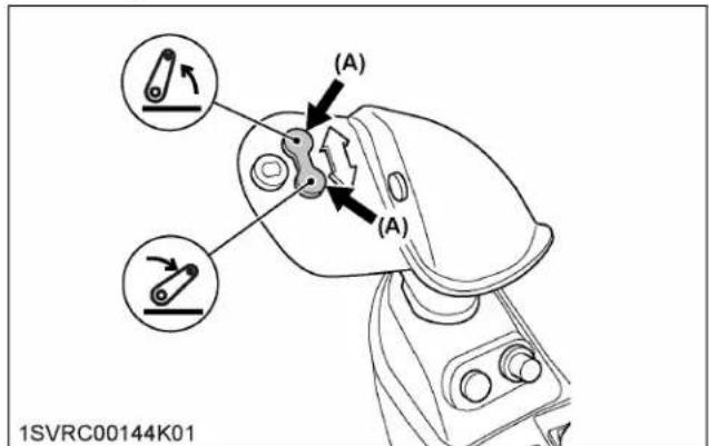

3-point quick raise switch
3-point quick lower switch
(A) "PUSH"
Premium, Premium KVT model


3-point quick raise switch
3-point quick lower switch
(A) "PUSH"
All models

(1) 3-point lifting and lowering indicator
NOTE :
- 3-point hitch working range: Set the depth control dial (hydraulic dial) for a bottom limit and the lift arm top limit adjustment dial or switch for a top limit. The 3-point quick raise and lower switches are controls for the raising and lowering within the limits set by the depth control dial (hydraulic dial) and the lift arm top limit adjustment dial or switch.
- One-touch floating function: Hold down the lower switch to keep the 3-point hitch floating. This function is helpful in plowing, for example. Release the switch and the 3-point hitch returns to the draft control position.
- Raise and lower operation with the 3-point hitch going halfway:
a. When the raise or lower switch is pressed with the 3-point hitch going up halfway, the 3-point hitch stops at this position (the indicator starts blinking). Re-push the raise or lower switch, and
the 3-point hitch will go up or down respectively.
b. To lower the 3-point hitch with the 3-point hitch going up halfway, hold down the lower switch for 2 seconds or push it twice.
c. When the raise switch is pressed with the 3-point hitch going down halfway, the 3-point hitch goes up.
12. 3-point hitch's position lock
Activating the lock
If any of the following actions are made with the depth control dial (hydraulic dial) and the lower links at different heights, the position lock is activated. The 3-point hitch control is interrupted and the 3-point lifting and lowering indicator starts flashing (2 or so flashes every second).
- Starting the engine.
- Activating the 3-point remote hitch "UP" switch or "DOWN" switch.
- Unlocking the 3-point hitch lock button.
Releasing the lock
- If applied, press the 3-point quick raise switch or 3-point quick lower switch.
- Turn the depth control dial (hydraulic dial) to the same level as the lift arm height.
NOTE :
- When the position lock is released with the 3-P. quick raise or lower switches, the 3-point hitch goes up or down.
13. Ride control
This function ensures stable run and comfortable ride when the tractor has a heavy-duty implement mounted on its rear 3-point hitch and travels along an uneven road.
Ride control gets activated when the following conditions are met :
- The ride control switch is on.
- The 3-point hitch lock button is unlocked.
- The traveling speed is over 6 km/h / 3.7 mph (automatically deactivated at below 5 km/h / 3.1 mph).
- The implement is almost at its top limit.
For Standard and Deluxe models:
- Press the ride control switch, and the switch indicator lights up and the ride control function gets activated.
- Press the switch again, and the switch indicator goes off and the ride control function gets deactivated.

(1) Ride control switch
(A) "PUSH"
For Premium and Premium KVT models:
- Touch the left half of the ride control switch, and the ride control function gets activated.
The ride control indicator stays on while the dumping control is in action.
- Press the right half of the switch, and the indicator goes off and the ride control function gets deactivated.
Details regarding the setting procedure can be found in a different section.
(See Setting the 3-point hitch on page 72.)

1SVRC00157H02
(1) Ride control indicator
(2) Ride control switch
NOTE :
- Once the ride control gets started, the implement will be slightly lowered.
AUXILIARY HYDRAULICS
IMPORTANT :
- Before letting a large amount of oil into the hydraulic cylinder, hydraulic motor or other implements, consult your local KUBOTA Dealer to confirm the possible oil quantity and
additional oil quantity taken from the tractor and other requirements.
Improper handling may cause serious trouble such as seizure of the transmission.
1. Power-beyond type hydraulic outlet for Deluxe, Premium and Premium KVT models (if equipped)
The power-beyond type hydraulic outlet is a load sensing type port through which a large amount of oil can be directly taken out of the hydraulic pump.
Connect an implement, equipped with a closed-center hydraulic valve, to this port.
With all necessary hoses in place, the load sensing control hose serves to detect the load level as a negative one. The pump's flow rate is thus controlled to keep constant the load sensing differential pressure, which is the difference between the pump pressure and this negative pressure.

(1) Load-sensing control hose connection
(2) Power-beyond connection (from pump)
(3) Return hose connection (from implement)
2. Hydraulic drain port
This port leads to the transmission case. When you want to return oil to the transmission case, connect the return hose to this port.

(1) Drain hose connection (to gear box)
REMOTE HYDRAULIC CONTROL SYSTEM
IMPORTANT :
- Before letting a large amount of oil into the hydraulic cylinder, hydraulic motor or other implements, consult your local KUBOTA Dealer to confirm the possible oil quantity and additional oil quantity taken from the tractor and other requirements. Improper handling may cause serious trouble such as seizure of the transmission.
1. Operation of Standard and Deluxe models
1.1 Controls of remote valves
The external hydraulic power can be taken out of up to 4 segments. Depending on different-destination models and mounted options, however, the number of ports varies.
In this manual, the 4-segment system is taken as an example.
Carefully check the relation between each valve and control lever before connecting the hydraulic hoses.

(1) Remote control valve lever 1
(2) Remote control valve lever 2
(3) Remote control valve lever 3
(4) Remote control valve lever 4
(5) Remote valve for lever 1
(6) Remote valve for lever 2
(7) Remote valve for lever 3
(8) Remote valve for lever 4
1.2 Remote control valve
The auxiliary control valve type comes in 3 types A, B, and C, as shown in the following table. All 3 types are double active valve type.
| Type A valve | Self canceling detent valve with float position and flow control. |
| Type B valve S | Self canceling detent valve with float position. |
| Type C valve | Mechanical detent valve with float position and flow control. |
Factory installed valve types are as follows:
3 valve model
| 1st 2nd 3rd | ||
| Type A Type B | Type C |
4 valve model
| 1st 2nd 3rd 4th | ||
| Type A Type B Type C Type B |
- Self canceling detent
This type of valve may be placed in detent mode. The lever will stay in this detent position until the pressure reaches a predetermined level or a cylinder reaches the end of its stroke. Then it will automatically return to neutral.
- Mechanical detent
This type of valve may be placed in detent mode. The lever will stay in this detent position without self canceling. Therefore, this type is suited for the continuous hydraulic work such as hydraulic pump.
- Float position
This type of valve may be placed in float mode with the control lever all the way forward. The cylinder is free to extend or retract, letting an implement such as a loader bucket follow the ground.
1.3 Flow control valve

WARNING
To avoid the possibility of personal injury or death be aware of the following when making adjustments:
- The 3-point hitch operation is influenced by the combination of the adjustment of the flow control valve and the engine speed.
- The 3-point hitch may rise slowly or not at all at low engine rpm.
- The 3-point hitch may rise suddenly if engine rpm is increased or if flow control adjustment is changed.

(1) Remote control valve with flow control
(2) Remote control valve with flow control
(3) Flow control knob for valve (1)
(4) Flow control knob for valve (2)
Adjusting the flow rate:
The flow rate for the remote control valve can be adjusted.
-
Turn the flow control knob counterclockwise (+), and the flow rate for the remote control valve increases. A clockwise turn (-) of the knob causes the flow to decrease. If the knob is turned all the way (A), there will be no flow.
-
To adjust the flow rate, set the engine speed to the operating rpm, turn the flow control knob once all the way clockwise (A), and then turn it gradually counterclockwise until the required flow rate is reached.
IMPORTANT :
- When there is no need to adjust the flow rate, turn the flow control knob all the way counterclockwise and keep it in this position.

(1) Remote control valve with flow control
(2) Flow control knob for valve
(+) "INCREASE"
(-) "DECREASE"
(A) "STOP"
1.4 Remote control valve lever
The remote control valve lever directs pressurized oil flow to the implement hydraulic system.
Each lever can be switched among its 4 positions.
Set the lever to the "FLOAT" position, and the lever is kept at that position.

(1) Remote control valve lever (A) "EXTEND"
(B) "RETRACT"
(N) "NEUTRAL"
(C) "FLOAT"
2. Operation of Premium and Premium KVT models
2.1 Controls of remote valves
The external hydraulic power can be taken out of up to 6 segments. Depending on different-destination models and mounted options, however, the number of ports varies.
In this manual, the 6-segment system is taken as an example.
Carefully check the relation between each valve and control switch before connecting the hydraulic hoses.

(1) Remote control valve switch 1
(2) Remote control valve switch 2
(3) Remote control valve switch 3
(4) Remote control valve switch 4
(5) Remote control valve switch 5
(6) Remote control valve switch 6
(7) Remote control valve switch (5-6) and loader joystick (Loader type)
(8) Remote valve for switch 1
(9) Remote valve for switch 2
(10) Remote valve for switch 3
(11) Remote valve for switch 4
(12) Remote valve for switch 5
(13) Remote valve for switch 6
2.2 Remote control valve lock button

WARNING
To avoid personal injury or death:
- Before road traveling, be sure to lock the remote control valve with this button to avoid accidentally dropping the implement.
Each time you press the switch, the lock and unlock status switch. The indicator of the switch stays on while in the lock status.

(1) Remote control valve lock button
2.3 Detailed setting of remote control valve
All the remote control valves can be preset in detail and their settings can be confirmed.
(See Setting the remote control valve on page 74.)
Locking and unlocking all the remote control valves
- Touch the left half of the switch (7), and all the remote control valves are locked and cannot be used for raising and lowering.
- Touch the right half of the switch, and the valves are unlocked.
While the remote control valves are locked, the indicator (1) lights up.
Locking and unlocking each of the remote control valves
- Touch any of the remote control valves lock and unlock switches (8), and the relevant remote control valve can be locked and unlocked. The following figure shows that the 3rd segment is being locked.

(1) Collective remote control valve lock indicator
(2) Priority valve indicator
(3) Valve operating status indicator
(4) Discharge rate from cylinder (extend) port
(5) Discharge rate from cylinder (retract) port
(6) Valve operating time
(7) Collective remote control valve lock switch
(8) Individual remote control valve lock and unlock switch
(9) Timer mode indicator
Flow rate and timer
The flow rate in both directions of the remote control cylinders and their operating time can be preset (timer-controlled).
NOTE :
- First set the switch to the "EXTEND" or "RETRACT" position. Then release your hand, and the timer starts counting. When the time is over, the oil feed to the implement is stopped. From now on, the timer can be preset with the switch alone.
If the switch is held at the "EXTEND" or "RETRACT" position, the oil feed is continued even after the timer has stopped counting.
- When the switch or the lever is operated in the opposite way, the timer counting is cancelled.
- When the timer and detent function are used together, the valve can serve as a double-acting valve with detents and self canceling.
Securing the priority flow
Oil is preferentially fed from the hydraulic pump to a specified remote control valve.
Once the priority flow is ensured, the priority flow status indicator (2) lights up.

(1) Remote control valve operating status indicator
(2) Priority flow status indicator
(3) Automatic shut-off timer indicator
(4) Remote control valve number
(5) Previous screen resume switch
(6) Remote control valve lock and unlock switch
(7) Priority flow status on/off switch
(8) Automatic shut-off timer on/off switch
(9) Plus (+) switch
(10) Minus (-) switch
(11) Automatic shut-off timer control
(12) Discharge rate from cylinder (retract) control
(13) Discharge rate from cylinder (extend) control
2.4 Remote control valve switch
The remote control valve switches direct pressurized oil flow to the implement hydraulic system.
Use of remote valves 1 and 2
Each switch can be set at 5 positions.
If the switch is held at the "FLOAT" or "DETENT" position, the switch is held at that position.
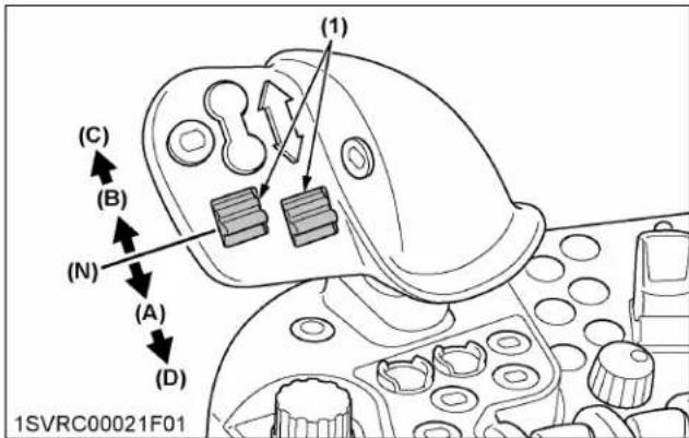
(1) Remote control valve switch (A) "EXTEND"
(B) "RETRACT"
(N) "NEUTRAL"
(C) "FLOAT
(D) "DETENT"
Use of remote valves 3 to 6
Each switch can be set at 5 positions.
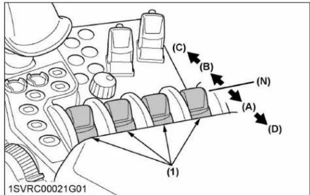
(1) Remote control valve switch (A) "EXTEND"
(B) "RETRACT"
(N) "NEUTRAL"
(C) "FLOAT"
(D) "DETENT"
2.5 Joystick for remote control valve and loader (loader model)
Using the joystick, the loader and the hydraulic remote control valves (5th and 6th) can be operated.
Each time you press the selection button, the remote control and the loader mode switch, and the respective indicator lights up.
If no such operation is needed, lock the joystick with its lock button.

(1) Joystick for remote control valve and loader
(A) "EXTEND"
(B) "RETRACT"
(2) Selection button for remote control valve and loader
(N) "NEUTRAL"
(3) Joystick lock button
(C) "FLOAT"
(4) Loader mode indicator
(5) Remote control valve mode indicator
(6) 5th valve operation
(7) 6th valve operation
NOTE :
- Moving the joystick diagonally provides flow for two valves simultaneously in the different combinations illustrated.
- If the front loader valve is not installed, the loader mode indicator (4) and remote control
valve mode indicator (5) are blinking. When the valve is installed, the indicator blinking is stopped.

flowchart
graph TD
    A["5"] --> B["6"]
    C["5"] --> D["6"]
    E["5"] --> F["6"]
    G["5"] --> H["6"]
    I["5"] --> J["6"]
    K["5"] --> L["6"]
    M["5"] --> N["6"]
    O["5"] --> P["6"]
    Q["5"] --> R["6"]
    S["5"] --> T["6"]
    U["5"] --> V["6"]
    W["5"] --> X["6"]
    Y["5"] --> Z["6"]
    AA["5"] --> AB["6"]
    AC["5"] --> AD["6"]
    AE["5"] --> AF["6"]
    AG["5"] --> AH["6"]
    AI["5"] --> AJ["6"]
    AK["5"] --> AL["6"]
    AM["5"] --> AN["6"]
    AO["5"] --> AP["6"]
    AQ["5"] --> AR["6"]
    AS["5"] --> AT["6"]
    AU["5"] --> AV["6"]
    AW["5"] --> AX["6"]
    AY["5"] --> Z
    AZ["5"] --> AA
    BA["5"] --> AB
    BB["5"] --> AC
    BC["5"] --> AD
    BD["5"] --> AE
    BF["5"] --> AG
    BG["5"] --> AH
    BH["5"] --> AI
    BI["5"] --> AJ
    BK["5"] --> AA
    BL["5"] --> AB
    BM["5"] --> AC
    BN["5"] --> AD
    BO["5"] --> AE
    BP["5"] --> AA
    BQ["5"] --> AB
    CA["5"] --> AC
    CB["5"] --> AD
    CC["5"] --> AE
    CD["5"] --> AF
    CE["5"] --> AG
    CF["5"] --> AH
    GA["5"] --> AI
    AH["5"] --> AJ
    AK["5"] --> AL
    AL["5"] --> AM
    AM["5"] --> AN
    AO["5"] --> AP
    AP["5"] --> AQ
    AQ["5"] --> BR
    BA["5"] --> AR
    AR["5"] --> AS
5th remote control valve
6th remote control valve
"EXTEND"
"RETRACT"
"FLOAT"
2.6 Controls for the remote control valves on the rear fender (if equipped)
The left and right tire fenders are equipped with the 2nd-segment remote control valve operation switch. Before activating the switch, make sure that there is nobody and no obstacle within the implement working range.
The valve acts only while the switch is held down.

(1) Extend switch for 2nd remote control valve
(2) Retract switch for 2nd remote control valve
3. Common operation for all models
3.1 Connecting cylinder and hydraulic motor
Connecting single-acting cylinder
-
Connect the hose to the lower coupler of the valve.
-
To extend a single-acting cylinder, move the control lever or switch to "EXTEND" (A) position.
Manually return the lever or switch to the "NEUTRAL" (N) position to stop the cylinder when it has reached the desired position.
- To retract a single-acting cylinder, move the lever or switch to "FLOAT" (C) position.
IMPORTANT :
- Always use the "FLOAT" (C) position to lower a single acting cylinder. The "RETRACT" (B) position is for double acting cylinders only.
- Do not hold the lever or switch in the "EXTEND" (A) position once the remote cylinder has reached the end of the stroke, as this will cause oil to flow through the relief valve. Forcing oil through the relief valve for extended periods will overheat the oil.
- Hold the lever or switch at the "FLOAT" (C) position, and the remote cylinder can be fully extended and retracted. Select this "FLOAT" (C) position when you want to run the implement along the terrain.

(A) "EXTEND"
(B) "RETRACT"
(N) "NEUTRAL"
(C) "FLOAT"
Connecting double-acting cylinder
- Connect the pressure of the load side of implement cylinders to the lower couplers of each valve, which have built in load check valves to prevent leaks.

(A) "EXTEND"
(B) "RETRACT"
(N) "NEUTRAL"
(C) "FLOAT"
(D) "DETENT"
IMPORTANT :
- Do not hold the lever or switch in the "EXTEND" (A) or "RETRACT" (B) position once the remote cylinder has reached the end of the stroke, as this will cause oil to flow through the relief valve. Forcing oil through the relief valve for extended periods will overheat the oil.
- Hold the lever or switch at the "FLOAT" (C) position, and the remote cylinder can be fully extended and retracted. Select this "FLOAT" (C) position when you want to run the implement along the terrain.
NOTE :
- Detent function:
Set the switch to the "DETENT" position, and it is held at this position unless it is returned to the "NEUTRAL" position.
This function is useful for implements that need constant oil feed.
Connecting hydraulic motor
- Connect the pressure hose (2) to the upper coupler and the return hose (3) to the lower coupler of the same valve.
- When the control lever or switch is assigned to the "FLOAT" (C) position, the motor is off.
- Move the lever or switch to "RETRACT" (B) position to operate the motor.
- To stop the motor, move the lever or switch from "RETRACT" (B) position to the "FLOAT" (C) position.
IMPORTANT :
- When operating continuous flow equipment, the remote control valve lever or switch must not be moved to the "NEUTRAL" (N) or "EXTEND" (A) position as damage to the equipment may result. Always select the motor mode function when operating with hydraulic motor.

(1) Hydraulic motor
(2) Pressure hose
(3) Return hose
(A) "EXTEND"
(B) "RETRACT"
(N) "NEUTRAL"
(C) "FLOAT"
3.2 Remote control valve coupler

WARNING
To avoid personal injury or death:
- Stop the engine and relieve pressure before connecting or disconnecting lines.
- Do not use your hands to check for leaks.
Connecting
- Clean both couplers.
- Remove dust plugs.
- Insert the implement coupler into the tractor hydraulic coupler.
- Pull the implement coupler slightly to make sure couplers are firmly connected.
Disconnecting
- Lower the implement to the ground to release hydraulic pressure from the hoses.
- Clean the couplers.
-
Relieve pressure by moving hydraulic control levers with engine shut off. Pull the hose straight from the hydraulic coupler to release it.
-
Clean oil and dust from the coupler, then replace the dust plugs.
NOTE :
- Your local Kubota Dealer can supply parts for adapting couplers to hydraulic hoses.
3.3 Remote couplers spillage collector
With the remote control valve coupler in place, a slight amount of oil leaking from the coupler is recovered. In this way, no oil is splashed around the tractor body.
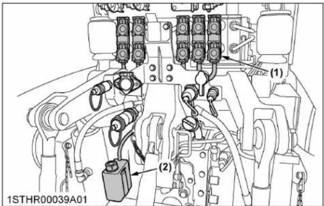
(1) Collector cap
(2) Oil tank
IMPORTANT :
- Oil recovered contains dust and water. Do not pour such oil back into the transmission case.
4. Hydraulic control unit use reference chart
In order to handle the hydraulics properly, the operator must be familiar with the following.
Though this information may not be applicable to all types of implements and soil conditions, it is useful for general conditions.
Standard, Deluxe models
| Implement |  1AGAIAZAP122ASoil condition 1AGAIAZAP122ASoil condition |  (2)1SVRC00038B01Top link mount-ing holes (2)1SVRC00038B01Top link mount-ing holes | 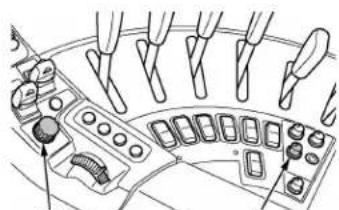 (2) 1SVRC00293A01(1) Draft ratio adjustment dial (draft sensitivity adjustment)(2) Depth control dial (hydraulic dial) (2) 1SVRC00293A01(1) Draft ratio adjustment dial (draft sensitivity adjustment)(2) Depth control dial (hydraulic dial) |  1AGAIAZAP070AGauge wheel (1) 1AGAIAZAP070AGauge wheel (1) |  1STHR00013A01Stabilizers 1STHR00013A01Stabilizers | |
| Moldboard plow | Light soilMedium soilHeavy soil | 2 | Turn the dial clockwise. Read-just according to the plowing depth or the soil condi-tion. | Turn the dial to the suitable posi-tion | Yes/No Unlock | |
| Disc plow — | ||||||
| Harrow (spike, spring-tooth, disc type). | — | |||||
| Subsoiler, and so on. | ||||||
| Weeder, ridge, and so on. | — 1 | Turn the dial fully counterclockwise. | Turn the dial to the suitable posi-tion | Yes | Lock | |
| Earthmover, dig-ger, scraper, manure fork, rear carrier, and so on. | Yes/No | |||||
| Mower (mid and rear-mount type) hayrake, tedder, and so on. | No | |||||
NOTE :
- With an implement mounted, use the top hole of the top link holder to keep the implement as horizontal as possible, and its bottom hole to keep the implement tilted forward.
Premium, Premium KVT models
| Implement |  1AGAIAZAP122ASoil condition 1AGAIAZAP122ASoil condition | 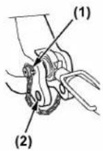 1SVRC00038B01Top link mount-ing holes 1SVRC00038B01Top link mount-ing holes |  (1) Draft sensitivity adjustment switch(2) Depth control dial (hydraulic dial) (1) Draft sensitivity adjustment switch(2) Depth control dial (hydraulic dial) |  1AGAIAZAP070AGauge wheel (1) 1AGAIAZAP070AGauge wheel (1) | 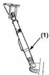 1STHR00013A01Stabilizers 1STHR00013A01Stabilizers | |
| Moldboard plow | Light soilMedium soilHeavy soil | 2 | Extend the graph to the right.Readjust according to the plowing depth or the soil condition. | Turn the dial to the suitable position | Yes/No Unlock | |
| Disc plow — | ||||||
| Harrow (spike, spring-tooth, disc type) | — | |||||
| Subsoiler, and so on. | ||||||
| Weeder, ridge, and so on. | — 1 | Set to the 0% level. | Turn the dial to the suitable position | Yes | Lock | |
| Earthmover, dig-ger, scraper, manure fork, rear carrier, and so on. | Yes/No | |||||
| Mower (mid and rear-mount type) hayrake, tedder, and so on. | No | |||||
NOTE :
- With an implement mounted, use the top hole of the top link holder to keep the implement as horizontal as possible, and its bottom hole to keep the implement tilted forward.
TIRES, WHEELS AND BALLAST
TIRES

WARNING
To avoid personal injury or death:
- Do not attempt to mount a tire on a rim. This should be done by a qualified person with the proper equipment.
- Always maintain the correct tire pressure. Do not inflate tires above the recommended pressure shown in the operator's manual.
IMPORTANT :
- Do not use tires other than those approved by Kubota.
1. Inflation pressure
Although the tire pressure is factory-set to the prescribed level, it naturally drops slowly in the course of time. Thus, check it every day and inflate as necessary.
NOTE :
- Maintain the maximum pressure in front tires if using a front loader or when equipped with a full load of front weights.
- When retrofitting the tractor with other tire combinations such as those described above or with special purpose tires, consult your local KUBOTA Dealer to get information regarding permitted tire combinations, tire pressure and additional information.
| Tire sizes Inflation pressure | ||
| Front | 14.9R28(380/85R28) | 160 kPa (23.2 psi.) |
| 14.9R30(380/85R30) | 160 kPa (23.2 psi.) | |
| 16.9R28(420/85R28) | 160 kPa (23.2 psi.) | |
| 540/65R28 160 kPa (23.2 psi.) | ||
| 320/85R34 240 kPa (34.8 psi.) | ||
| Rear | 18.4R38(460/85R38) | 160 kPa (23.2 psi.) |
| 18.4R42(480/80R42) | 160 kPa (23.2 psi.) | |
| 460/85R42 160 kPa (23.2 psi.) | ||
| 650/65R38 160 kPa (23.2 psi.) | ||
| 380/90R46 240 kPa (34.8 psi.) | ||
| 420/80R46 240 kPa (34.8 psi.) | ||
Tyre load capacity (kg) at tyre pressure (bar)
Front
540/65R28
| Pressure (bar) 10 | km/h 30 km | 40 km/h | 50 km/h | |
| 0.6 | 2180 | 1730 | 1640 | 1580 |
| 0.8 | 2455 | 2015 | 1910 | 1835 |
| 1.0 | 2725 | 2295 | 2180 | 2095 |
| 1.2 | 3000 | 2580 | 2450 | 2350 |
| 1.4 | 3250 | 2815 | 2675 | 2565 |
| 1.6 | 3500 | 3050 | 2900 | 2780 |
420/85R28
| Pressure (bar) 10 | km/h 30 km/h | 40 km/h | 50 km/h | |
| 0.6 | 1800 | 1300 | 1215 | 1105 |
| 0.8 | 2100 | 1500 | 1400 | 1275 |
| 1.0 | 2400 | 1710 | 1600 | 1460 |
| 1.2 | 2700 | 1925 | 1800 | 1640 |
| 1.4 | 2850 | 2130 | 1990 | 1810 |
| 1.6 | 3000 | 2335 | 2180 | 1985 |
380/85R30
| Pressure (bar) 10 | km/h 30 km | 40 km/h | 50 km/h | |
| 0.6 1680 1250 1180 | 1180 | |||
| 0.8 1905 1450 1360 | 1360 | |||
| 1.0 2130 1675 1555 | 1550 | |||
| 1.2 2360 1900 1750 | 1750 | |||
| 1.4 2580 2100 1965 | 1965 | |||
| 1.6 2800 2300 2180 | 2180 |
380/85R28
| Pressure (bar) 10 | km/h 30 km/h 40 km/h 50 km/h | |||
| 0.6 1490 1070 100 | 0 910 | |||
| 0.8 1745 1230 115 | 0 1045 | |||
| 1.0 2000 1420 132 | 0 1205 | |||
| 1.2 2250 1605 150 | 0 1365 | |||
| 1.4 2360 1765 165 | 0 1500 | |||
| 1.6 2475 1925 180 | 0 1640 | |||
320/85R34
| Pressure (bar) 10 | km/h 30 km | 40 km/h | 50 km/h | |
| 0.6 1410 1030 975 | 900 | |||
| 0.8 1610 1215 1120 | 1030 | |||
| 1.0 — — — — | ||||
| 1.2 2000 1550 1450 | 1320 | |||
| 1.4 — — — — | ||||
| 1.6 2430 1900 1750 | 1600 |
Rear
650/65R38
| Pressure (bar) 10 | km/h 30 km | 40 km/h | 50 km/h | |
| 0.6 3350 2650 252 | 20 2420 | |||
| 0.8 3775 3090 294 | 40 2820 | |||
| 1.0 4200 3530 336 | 60 3220 | |||
| 1.2 4625 3970 378 | 80 3620 | |||
| 1.4 5005 4335 415 | 100 3975 | |||
| 1.6 5390 4740 452 | 120 4330 |
480/80R42
| Pressure (bar) 10 | km/h 30 km | 40 km/h | 50 km/h | |
| 0.6 2840 2170 — | — | |||
| 0.8 3230 2465 2306 — | ||||
| 1.0 3591 2746 2566 2566 | ||||
| 1.2 3926 3001 2805 2805 | ||||
| 1.4 4376 3346 3126 3126 | ||||
| 1.6 4831 3690 3450 3450 |
460/85R42
| Pressure (bar) 10 | km/h 30 km | 40 km/h | 50 km/h | |
| 0.6 2690 2000 1850 | 1850 | |||
| 0.8 3050 2335 2170 | 2170 | |||
| 1.0 3305 2775 2640 | 2535 | |||
| 1.2 3775 3015 2810 | 2810 | |||
| 1.4 3970 3510 3345 | 3205 | |||
| 1.6 4500 3690 3450 | 3450 |
460/85R38
| Pressure (bar) 10 | km/h 30 km | /h 40 km/h | 50 km/h | |
| 0.6 2440 1710 1600 | 1455 | |||
| 0.8 2840 2035 1900 | 1730 | |||
| 1.0 3245 2320 2165 | 1970 | |||
| 1.2 3645 2600 2430 | 2210 | |||
| 1.4 3810 2905 2715 | 2470 | |||
| 1.6 3975 3210 3000 | 2730 |
420/80R46
| Pressure (bar) 10 | km/h 30 km | /h 40 km/h | $0 km/h | |
| 0.6 2340 1700 1600 | 1450 | |||
| 0.8 2675 2000 1850 | 1700 | |||
| 1.0 — — — — | ||||
| 1.2 3350 2575 2430 | 2240 | |||
| 1.4 — — — — | ||||
| 1.6 4000 3150 2900 | 2650 |
380/90R46
To avoid personal injury or death:
- Before jacking up the tractor, park it on a firm and level ground and chock the wheels.
• Fix the front axle to keep it from pivoting. - Select jacks that withstand the machine weight and set them up as shown below.
When using a jack, be sure to set the jack at the position indicated on the label and illustration.
If the jack is positioned incorrectly, it may damage the tractor.

(1) Jack point
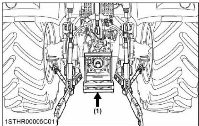
(1) Jack point
3. Safe replacement of the wheel
The wheel is heavy. Take the following precautions when removing the wheel.
- Park the tractor on a solid, level place.
- Apply the parking brake and use chocks.
- In detaching the rear wheels, apply a wedge in place to keep the front axle from oscillating.
- Use a jack or the like that withstands the relevant weight.
- Use an appropriate tire remover.
- Tighten the bolts and nuts to their specified torques.
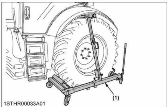
natural_image
Technical line drawing of a tractor with a wheeled cart and tire assembly (no text or symbols)(1) Tire remover
WHEEL ADJUSTMENT

WARNING
To avoid personal injury or death:
- When working on slopes or when working with a trailer, set the wheel tread as wide as practical for maximum stability.
- Support the tractor securely on stands before removing a wheel.
- Do not work under any hydraulically supported devices. They can settle, suddenly leak or be accidentally lowered. If necessary to work under the tractor or any machine elements for servicing or adjustments, securely support them with stands or suitable blocking beforehand.
- Never operate the tractor with a loose rim, wheel or axle.
1. Adjusting front wheels with 4-wheel drive
Front tread width can be adjusted as shown with the standard equipped tires.
To change the tread width:
- Remove the wheel rim and disk mounting bolts.
- Change the position of the rim and disk (right and left) to the desired position, and tighten the bolts.
- Adjust the toe-in [0 to 8 mm (0.0 to 0.3 in).] (See Adjusting toe-in on page 256.)
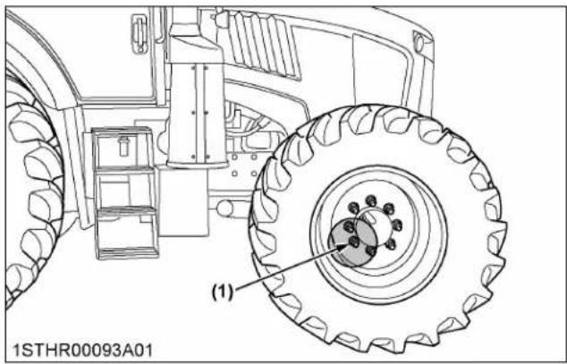
(1) 540 N m (55.1 kgf m) (398 ft lbs.)
| (KW6X) | 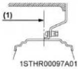 | 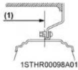 |  |  |  | |
| (1) Tread | ||||||
| 420/85R28380/85R28380/85R30320/85R34 | 1537 mm(60.5 in.) | 1567 mm(61.7 in.) | 1603 mm(63.1 in.) | 1633 mm(64.3 in.) | 1741 mm(68.5 in.) | 1771 mm(69.7 in.) |
| (1) Tread | (1)1STHR00102A01 | (1)1STHR00103A01 | (1)1STHR00129A01 | (1)1STHR00130A01 | (1)1STHR00131A01 | (1)1STHR00132A01 |
| 420/85R28380/85R28380/85R30320/85R34 | 1807 mm(71.1 in.) | 1837 mm(72.3 in.) | 1937 mm(76.3 in.)*1 | 1967 mm(77.4 in.) | 2003 mm(78.6 in.) | 2033 mm(80.0 in.) |
| (1) Tread (1) Tread | (1)1STHR00133A01 | (1)1STHR00134A01 | (1)1STHR00135A01 | (1)1STHR00136A01 | (1)1STHR00104A01 | |
| 420/85R28380/85R28380/85R30320/85R34 | 2141 mm(84.3 in.) | 2171 mm(85.5 in.) | 2207 mm(86.9 in.) | 2237 mm(88.1 in.) | 540/65R28 | 1900 mm(74.8 in.)*1 |
*1 Recommended tread width with front loader operation.
NOTE :
- Adjust steering stopper bolt to ensure tires do not contact the tractor frame or implement.
IMPORTANT :
• Always attach wheels as shown in the drawing.
- If not attached as illustrated, transmission parts may be damaged.
- When re-fitting or adjusting a wheel, tighten the bolts to the following torques then recheck after driving the tractor 200m (200 yards) and 10 times of shuttle movement by 5 m (5 yards), and thereafter according to service interval. (See MAINTENANCE on page 230 and Checking wheel bolt torque on page 249.)
2. Adjusting the front wheel turning stopper bolt
- Check the front wheel turning angle each time the front wheels are changed.
Proceed as follows:
a. Apply the parking brake.
b. Immobilize the tractor using wheel chocks.
c. Raise the front of the tractor.
d. Turn the steering wheel full lock to the left and subsequently to the right or vice versa and pivot the axle to its position of maximum oscillation.
- When the front axle is in the condition of maximum oscillation and the wheels are turned to the maximum angle, there must be no interference between the fenders or tires and engine hood or loader frame.
If necessary, adjust the stopper bolts.

(1) Stopper bolt (L) Bolt length
| Bolt length (L) | |
| 14.9R28 (380/85R28) | 85 mm (3.35 in.) |
| 14.9R30 (380/85R30) | |
| 16.9R28 (420/85R28) | |
| 320/85R34 | |
| 540/65R28 65 mm (2.56 in.) | |
| Swing stopper option (if equipped) | 115 mm (4.53 in.) |
3. Adjusting rear wheels with flange type axle
Rear tread width can be adjusted as shown with the standard equipped tires.
To change the tread width:
- Remove the wheel rim and / or disk mounting bolts.
- Change the position of the rim and / or disk (right and left) to the desired position, and tighten the bolts.
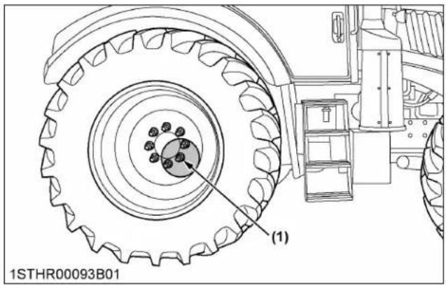
natural_image
Technical line drawing of a tractor wheel assembly with gear and mounting bracket (no text or symbols)(1) 670 N m (68.3 kgf m) (494 ft lbs.)
| (1) Tread |  |  |  | 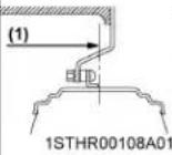 |  | 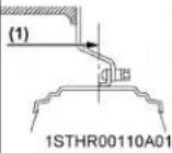 | 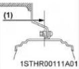 |
| 480/80R42460/85R38460/85R42420/80R46380/90R46 | 1582 mm(62.3 in.) | 1612 mm(63.5 in.) | 1656 mm(65.2 in.) | 1686 mm(66.4 in.) | 1778 mm(70.0 in.) | 1808 mm(71.2 in.) | 1852 mm(72.9 in.) |
| (1) Tread (1) Tread |  |  |  |  | 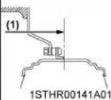 | (1)1STHR00112A01 | ||
| 480/80R42460/85R38460/85R42420/80R46380/90R46 | 1882 mm(74.1 in.) | 1982 mm(78.0 in.)*1 | 2012 mm(79.2 in.) | 2056 mm(80.9 in.) | 2086 mm(82.1 in.) | 650/65R38 | 1814 mm(71.4 in.)*1 | |
| 650/65R38 | 1814 mm(71.4 in.)*1 |
*1 Recommended tread width with front loader operation.
IMPORTANT :
• Always attach wheels as shown in the drawing.
- If not attached as illustrated, transmission parts may be damaged.
- When re-fitting or adjusting a wheel, tighten the bolts to the following torques then recheck after
driving the tractor 200 m (200 yards) and 10 times of shuttle movement by 5 m (5 yards), and thereafter according to service interval. (See MAINTENANCE on page 230 and Checking wheel bolt torque on page 249.)
4. Adjusting wheels with bar type axle
Rear tread width can be adjusted as shown with the standard equipped tires.
To change the tread width:
- Clean the axle with a wire brush.
- Keep the wheel whose tread will be readjusted slightly above the floor.
- Depending on the number of bolts, the procedure for step 3 differs as follows:
- For 10 bolts fix type:
a. There are 6 bolts. Remove 4 bolts (A, C, D, F) and loosen the other two (B, E).
b. Apply the removed 4 bolts into the jack bolt holes. Tighten up these 4 bolts evenly and draw out the tire flange.
c. Slide the wheel to a desired tread width.
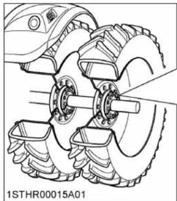
natural_image
Technical line drawing of a mechanical assembly with multiple gears and a shaft (no text or symbols)
(1) Screw hole for jack up

(1) Bar axle
(2) Retainer
(3) Tire flange
(4) Wheel disc
(5) 4-jack bolts
(6) Bolt
- For 8 bolts fix type:
a. There are 4 flange bolts. Remove the 2 diagonally opposite to each other and loosen the other two.
b. Apply the removed 2 bolts into the jack bolt holes. Tighten up these 2 bolts evenly and draw out the tire flange toward yourself.
c. Slide the wheel to a desired tread width. If the retainer and the bar axle are stuck too hard to slide the wheel, drive a wedge in the retainer's slot for smooth motion.

(1) Screw hole for jack up

(1) Bar axle
(2) Retainer
(3) Tire flange
(4) Wheel disc
(5) 2-jack bolts
(6) Bolt

(1) Retainer
(A) "SLOT"
-
Remove the jack bolts and fix the tire flange and retainer with the bolts.
-
Use the same procedure for the other-side wheel.
NOTE :
- For easy tread width readjustment, preferably dismount the rear wheel ballast to lighten the total weight of the wheel.
• After readjusting to a new tread width, make sure there is enough clearance between the tire and tire fender, as well as between the tire and lower link.
IMPORTANT :
• Always attach wheels as shown in the drawing.
- If not attached as illustrated, transmission parts may be damaged.
- When re-fitting or adjusting a wheel, tighten the bolts to the following torques then recheck after driving the tractor 200 m (200 yards) and 10 times of shuttle movement by 5 m (5 yards), and thereafter according to service interval.
(See MAINTENANCE on page 230.)
10 bolts fix type

(1) 543 N · m (55.4 kgf · m) (400 ft · lbs.)
(2) 670 N · m (68.3 kgf · m) (494 ft · lbs.)
8 bolts fix type
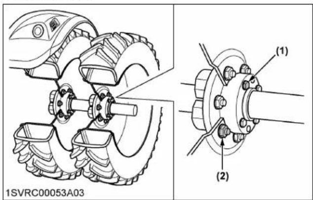
(1) 350 N · m (35.7 kgf · m) (258 ft · lbs.)
(2) 670 N m (68.3 kgf m) (494 ft lbs.)

Dual wheels may be used on the rear axles of tractors for the purpose of flotation or soil compaction reduction only. They are recommended for use in the field. When traveling on road, you must comply with local regulation at all time.
IMPORTANT :
- Do not install dual wheels on the front axle.
1. Bar type axle
Attach the wheels onto the rear axle.

natural_image
Technical line drawing of a mechanical assembly with gears and a central shaft (no text or symbols)2. Flange type axle
A dual-tire adapter mounted to the tractor's rear wheel flange is available as an option.
BALLAST

WARNING
To avoid personal injury or death:
• Additional ballast will be needed for transporting heavy implements. When the implement is raised, drive slowly over rough ground, regardless of how much ballast is used.
- Do not fill the front wheels with liquid to maintain steering control.
1. Front ballast
Add weights if needed for stability and improved traction.
Heavy pulling and heavy rear mounted implements tend to lift up the front wheels.
Add enough ballast to maintain steering control and to prevent tipping over. Remove the weight when it is no longer needed.
1.1 Front end weights (option)
Front end weights can be attached to the bumper.
See your implement operator's manual for required number of weights or consult your local Kubota Dealer about their usage.

(1) Front end weights
(2) Bumper
IMPORTANT :
- Do not overload tires.
- Add no more weight than indicated in chart.
- Do not attach the front bumper when the front loader is attached.
| Maximum weight | 45 kg x 14 pieces(1389 lbs.) |
2. Rear ballast for single tires
Add weight to rear wheels if needed to improve traction or for stability.
The amount of rear ballast should be matched to job and the ballast should be removed when it is not needed.
The weight should be added to the tractor in the form of liquid ballast, rear wheel weights or a combination of both.
2.1 Rear wheel weights (option)
Rear wheel weights can be attached to the rear wheel. See your implement operator's manual for required number of weights or consult your local KUBOTA Dealer about their usage.

(1) Rear wheel weights
IMPORTANT :
- Do not overload the tires.
- Add no more weight than indicated in the chart.
Maximum weight per wheel 445 kg (981 lbs.)
2.2 Liquid ballast in rear tires
A water and calcium chloride solution provides safe and economical ballast. Used properly, it will not damage tires, tubes or rims. The addition of calcium chloride is recommended to prevent the water from freezing.
Use of this method of weighting the wheels has the full approval of the tire companies.
See your tire dealer for this service.
Liquid weight per tire (75% filled)
| Tire sizes 380/90R46 420 | /80R46 460/85R38 | ||
| Slush free at -10 °C(14 F)Solid at -30 °C (-22 F)(Approx.1 kg (2 lbs.)CaCl2 per 4 L (1 gal.) of water) | 272 kg(600 lbs.) | 288 kg(635 lbs.) | 411 kg(906 lbs.) |
| Slush free at -24 °C(-11 F)Solid at -47 °C (-53 F)(Approx.1.5 kg (3.5 lbs.)CaCl2 per 4 L (1 gal.) of water) | 306 kg(675 lbs.) | 324 kg(714 lbs.) | 463 kg(1021 lbs.) |
| Slush free at -47 °C(-53 F)Solid at -52 °C (-62 F)(Approx.2.25 kg (5 lbs.)CaCl2 per 4 L (1 gal.) of water) | 333 kg(734 lbs.) | 353 kg(778 lbs.) | 503 kg(1109 lbs.) |
| Tire sizes 480/80R42 650/65R38 | ||
| Slush free at -10 °C(14 °F)Solid at -30 °C (-22 °F)(Approx.1 kg (2 lbs.)CaCl2 per 4 L (1 gal.) of water) | 401 kg(884 lbs.) | 575 kg(1268 lbs.) |
| Slush free at -24 °C(-11 °F)Solid at -47 °C (-53 °F)(Approx.1.5 kg (3.5 lbs.)CaCl2 per 4 L (1 gal.) of water) | 451 kg(994 lbs.) | 646 kg(1424 lbs.) |
| Slush free at -47 °C(-53 °F)Solid at -52 °C (-62 °F)(Approx.2.25 kg (5 lbs.)CaCl2 per 4 L (1 gal.) of water) | 490 kg(1080 lbs.) | 703 kg(1550 lbs.) |
NOTE :
- On a 50 km/h (31.1 mph) specifications tractor, filling tires with liquid ballast is not recommended.
IMPORTANT :
- Do not fill tires with water or solution to more than 75% of full capacity (to the valve stem level).

(1) Air
(2) Water
(A) Correct - 75% full, air compresses like a cushion
(B) Incorrect - 100% full, water cannot be compressed
2.3 Monolithic block (if equipped)
The monolithic block allows the operator to install a weight at the front or rear 3-point hitch.

(1) Monolithic block
2.4 Maximum masses
(See APPENDICES on page 294.)
CAB OPERATION
CAB CLASSIFICATION AND MAINTENANCE
The CAB fulfills the requirements of category type 2.

natural_image
Technical line drawing of a vehicle cockpit with steering wheel and control panels (no text or symbols)(1) CAB classification label
The air delivery and filtration system of the category 2 CAB protects against airborne and sedimented solid particles.
The system increases the pressure in the CAB, which helps prevent dust from entering the CAB. As additional protection against dust, the category 2 CAB is also equipped with a fresh air filter.
However, in order for the filtration system to function as intended, the following conditions must be met:
- Door and window seals in good condition.
- Doors and windows closed.
- CAB grommets for cables properly sealed.
- Blower switch set to highest setting and recirculation/ fresh air selection switch set to "FRESH AIR" position.
• CAB air filters in good condition.
Make sure to follow the available instructions of the personal protective equipment (PPE), plant protection products (PPP), sprayer manufacturer and the national guidelines for worker safety and health regarding, for example:
- Using PPE
- Training and education
- Keeping used PPP out of the CAB
- Removing contaminated shoes or clothing before entering the CAB
- Keeping the CAB interior clean
- Disposal of filters
Clean the inner air filter and fresh air filter at the required service intervals to assure that the category 2 delivery and filtration system is functioning as intended.
(See Cleaning inner air filter on page 256.)
(See Cleaning fresh air filter on page 256.)
DOORS AND WINDOWS
1. Locking and unlocking the door
From the outside:
Insert the key into the door lock. Turn the key clockwise to unlock the door. To lock the door, turn the key in the opposite direction.
The key can be removed when it is in the vertical position.
From the inside:
Push down the lock knob to lock the door. Pull up the lock knob to unlock the door.
2. Opening the door
From the outside:
Unlock the door, and pull the outer door handle.

(1) Outer door handle
(2) Door lock
(A) "PULL"
From the inside:
Unlock the door and pull the inner door handle.

(1) Inner door handle
(A) "PULL"
(2) Lock knob
(B) "PUSH" (lock)
(C) "PULL" (unlock)
3. Rear window
Turn the rear window handle clockwise to the vertical position and push the handle. The rear window is opened by the gas spring cylinder.

(1) Rear window handle (A) "OPEN"
(B) "CLOSE"
4. Sun roof

WARNING
To avoid personal injury or death:
- Front loader must be used with the sun roof closed.
Raise the front loader, and visually check to see if the tip of an attachment (bucket and fork, for example) is visible in its position or angle from the operator's seat.
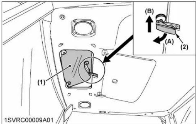
(1) Sun roof
(A) "PULL"
(2) Sun roof handle
(B) "PUSH" (open)
NOTE :
- Open the sun roof, to allow outside air in.
5. Emergency exit
-
In an emergency situation, open the right door of the CAB if the left door is blocked and vice versa.
-
Exit through the rear window if the CAB doors are blocked.
DOME LIGHT
Sliding the dome light switch will give the following light condition:
[OFF]
The light does not turn on when the door is opened.
"DOOR"
The light turns on when the door is opened. It turns off when the door is closed.
[ON]
The light remains on regardless of the door position.
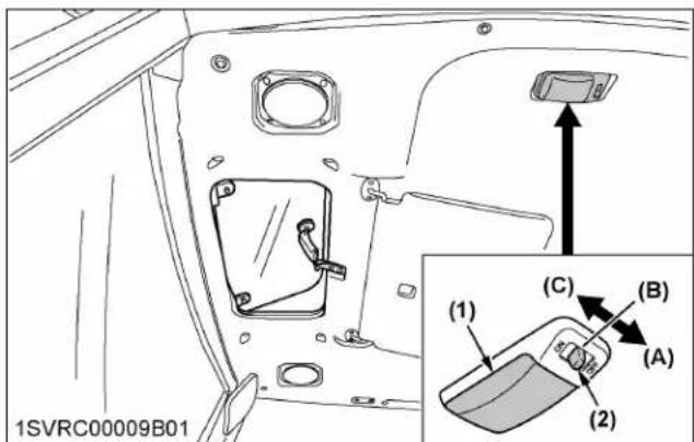
(1) Dome light
(A) [OFF]
(2) Dome light switch
(B) "DOOR"
(C) [ON]
IMPORTANT :
- The battery will discharge if the dome light remains on. Be sure to check the dome light switch position and/or door closure.
SPOT LIGHT (IF EQUIPPED)
The spotlight is directed on the armrest and right hand console.

(1) Spotlight
(A) "ON"
(2) Switch
(B) "OFF"
WIPER
1. Front wiper and washer switch
- Turn on the key switch and turn the front wiper and washer switch clockwise or anti-clockwise to activate the wiper.
- When the front wiper and washer switch is pressed, washer liquid jets out.
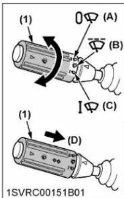
(1) Front wiper and washer switch

natural_image
Line drawing of a car interior showing steering wheel, dashboard, and steering wheel (no text or symbols)(A) "OFF"
(B) "INTERMITTENT"
(C) "CONTINUOUS"
(D) "PUSH"
IMPORTANT :
- Do not activate the wipers when the windows are dry, as they may be scratched.
Be sure to jet washer liquid first and then activate the wipers.
2. Rear wiper and washer switch
- Turn on the key switch and press the bottom half of the wiper switch to the first stage, activating the wiper.
- When the switch is pressed down to the second stage, washer liquid jets out.
The jetting continues while the switch is pressed and the wiper is activated continuously.

(1) Rear wiper and washer switch
(A) "WIPER"
(B) "WIPER and WASHER"
IMPORTANT :
- Do not activate the wipers when the windows are dry, as they may be scratched. Be sure to jet washer liquid first and then activate the wipers.
3. Using the wipers in cold season
- While not used in cold season, keep the wiper blades off the windshield to prevent them from being frozen to the windshield.
- If the windshield is covered with snow, scrape it off the windshield before using the wipers.
- If the wiper blades are frozen to the windshield and fail to move, be sure to turn the main key switch to "OFF" and remove the ice from the blades. Then place the main key switch back to "ON".
- When commercially available cold-season wiper blades are used, make sure their size is the same as or smaller than that of the standard ones.
IMPORTANT :
- In the cold season, the wiper blades and the wiper motor may become overloaded, and cause damage. To avoid this, be sure to take the above precautions.
AIR CONDITIONER

CAUTION
To avoid personal injury:
- If the window fails to defrost in extreme conditions or becomes cloudy when dehumidifying the CAB, wipe off moisture with a soft cloth.
- Do not block all the air outlets of the air conditioner. A problem could occur.
1. Airflow
Air in the CAB and fresh air introduced into the CAB flows as follows. Adjust the air ports to obtain the desired condition.

(1) Defroster air outlets
(2) Dashboard air outlets
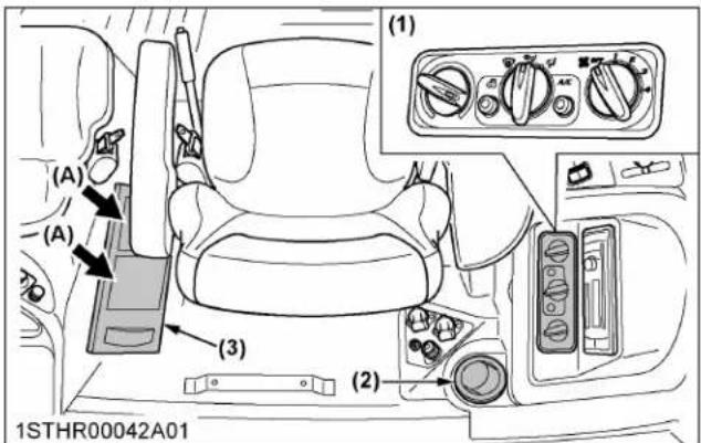
(1) Control panel
(2) Rear air outlet
(3) Inner air filter
(A) Inner air recirculation

(1) Fresh air filter (A) "FRESH AIR INLET"
IMPORTANT :
- Do not pour water directly into the fresh air port while washing the tractor.
2. Air control vent
2.1 Dashboard air outlet
The dashboard air outlets can be independently adjusted as required.
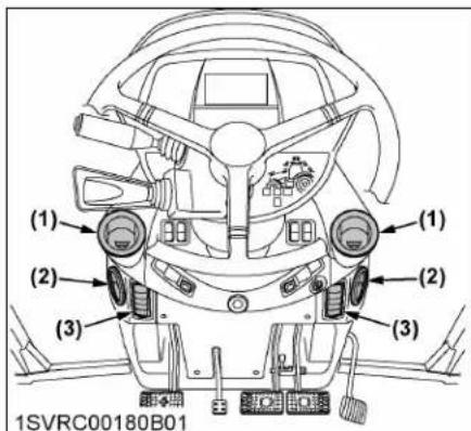
(1) Face area air outlets
(2) Back area air outlets
(3) Feet area air outlets
(A) "OPEN"
(B) "SHUT"
(C) "TURN"

2.2 Rear air outlet
The rear air outlet is connected with the dashboard air outlets.
In summer when the back of the operator is exposed to sunlight, keep the rear air outlet open, and cool air is blown out of the front and rear air outlets for comfortable operation.

(1) Rear air outlet
3. Control panel
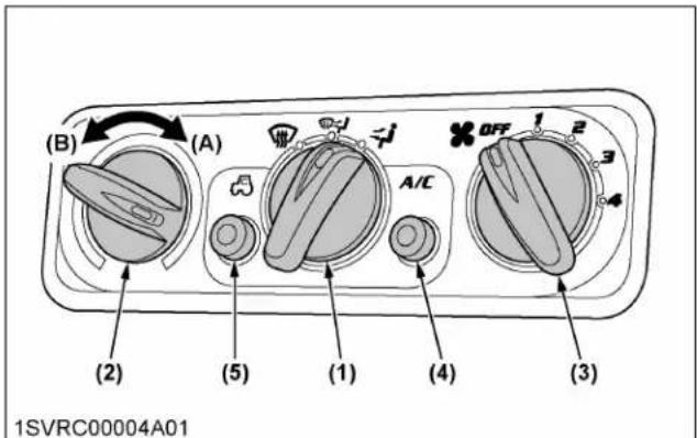
(1) Mode switch
(A) "WARM"
(2) Temperature control dial
(B) "COOL"
(3) Blower switch
(4) Air conditioner switch with indicator light
(5) Recirculation and fresh air selection switch with indicator light
3.1 Mode switch
Set the mode switch to the desired position.
Air is blown from the dash board and rear air outlets.
Air is blown from the dashboard, defroster and rear air outlets.
Air is blown from only the defroster air outlets.
3.2 Temperature control dial
Set this dial at the desired position to obtain the optimum air temperature. Turn the dial in the "WARM" direction to obtain warmer air. Turn it in the "COOL" direction to obtain cooler air.
3.3 Blower switch
Air volume can be changed in 4 steps. At the [4] position, the largest air volume is obtained.
3.4 Air conditioner switch
Push this switch to activate the air conditioner. An indicator light will light up when the switch is set to "ON".
Push the switch again to turn the air conditioner off, in which case the indicator light will turn off.
3.5 Recirculation or fresh air selection switch
Each time the switch is pressed, the air flow position changes for "RECIRCULATION" or "FRESH AIR". An indicator light will light up when the switch is set to "RECIRCULATION". And the indicator light will be off when the switch is set to "FRESH AIR".
FRESH AIR:
Indicator: "OFF"
Fresh air will flow into the CAB. This is helpful when you work in dusty conditions or if the glass windows get foggy.
RECIRCULATION:
Indicator: "ON"
In-CAB air will be recirculated. This is useful for cooling or heating the CAB quickly or keeping it extra cool or warm.

(1) Recirculation or fresh air selection switch with indicator light
(A) "RECIRCULATION"
(B) "FRESH AIR"
NOTE :
- When heating, do not keep the switch at the "RECIRCULATION" position for a long time. The windshield easily gets foggy.
- While working in dusty conditions, keep the switch at the "FRESH AIR" position. This increases the pressure in the CAB, which helps prevent dust from coming into the CAB.
4. Operation
4.1 Heating
- Set the mode switch to the

position.
- Set the recirculation or fresh air selection switch to the "FRESH AIR" position. To raise the temperature in the CAB quickly, set this switch to the "RECIRCULATION" position.
- Adjust the blower ([1], [2], [3], or [4]) switch and the temperature control dial to achieve a comfortable temperature level.

(1) Mode switch
(A) "WARM"
(2) Blower switch
(B) "COOL"
(3) Temperature control dial
(4) Recirculation or fresh air selection switch with indicator light
- Adjust the air volume and air direction from the dashboard air outlets. In general, open feet area air outlets, and shut face and back area air outlets.
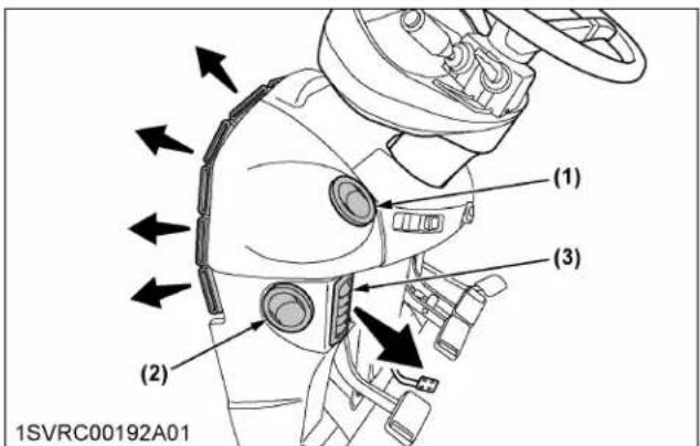
(1) Face area air outlets
(2) Back area air outlets
(3) Feet area air outlets
- To blow out warm air also from behind, open the rear air outlet and adjust the air direction.

(1) Rear air outlet
4.2 Cooling or dehumidifying-heating
- Set the mode switch to the position.
- Set the recirculation or fresh air selection switch to the "FRESH AIR" position. To lower the temperature in the CAB quickly, set this switch to the "RECIRCULATION" position.
- Press and turn on the air conditioner switch with indicator.
- Turn on the blower ([1], [2], [3], or [4]) switch.
- Adjust the temperature control dial to "COOL" or an intermediate position to achieve a comfortable temperature level.
NOTE :
- In summer when the heater is not used, keep the temperature control dial at the max "COOL" (end of counterclockwise) position. Otherwise, hot air will raise the temperature in the CAB.
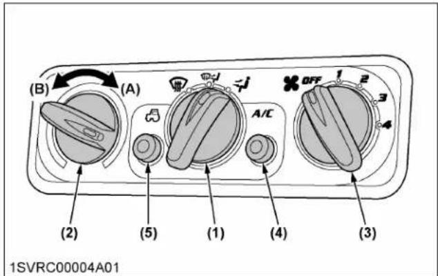
(1) Mode switch
(A) "WARM"
(2) Temperature control dial
(B) "COOL"
(3) Blower switch
(4) Air conditioner switch with indicator light
(5) Recirculation or fresh air selection switch with indicator light
- Adjust the air volume and air direction from the dashboard air outlets. In general, the air volume from face area air outlets is adjusted to increase, and the air volume from feet and back area air outlets is adjusted to decrease.

(1) Face area air outlets
(2) Back area air outlets
(3) Feet area air outlets
- To blow cool air from behind as well, open the rear air outlet and adjust the air direction.
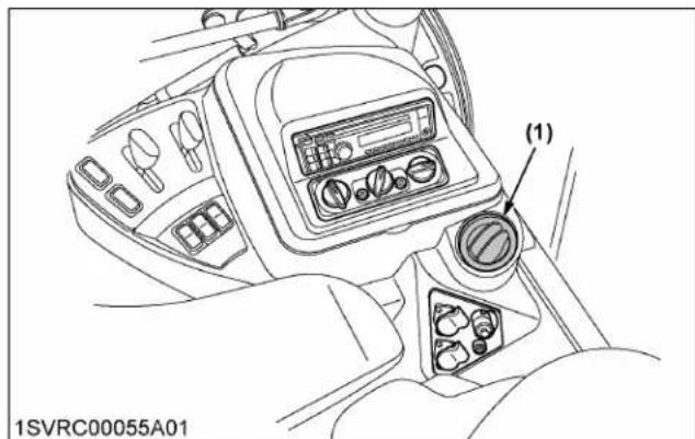
(1) Rear air outlet
4.3 Defrosting or demisting
To defrost or demist the windshield, take the following steps.
- Set the mode switch to the position.
- Set the recirculation or fresh air selection switch to the "FRESH AIR" position.
- Set the blower switch and the temperature control dial to the [4] and max "WARM" (end of clockwise) positions, respectively.

(1) Mode switch (A) "WARM"
(3) Temperature control dial (B) "COOL"
(2) Blower switch
(4) Recirculation or fresh air selection switch with indicator light

(1) Defroster air outlet
NOTE :
- If you set the mode switch to position, air will not come out from the dashboard and rear air outlets.
REAR DEFOGGER WITH TIMER (IF EQUIPPED)
To activate the rear window defogger, press the switch marked ☐ while the key switch is in the "ON" position. Then, the yellow light on the switch turns on.
After about 15 minutes, the defogger and the yellow light turn off automatically. To turn the defogger off, press the switch once more.
Standard, Deluxe models
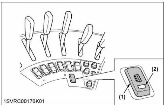
(1) Defogger switch
(2) Yellow light
Premium, Premium KVT models

(1) Defogger switch
(2) Yellow light
IMPORTANT :
- The battery will discharge if the defogger and the key switch remain in the "ON" or "ACC" positions with the engine stopped. Always use the defogger with the engine running.
ACCESSORIES
1. Trailer electrical outlet
A trailer electrical outlet is supplied for use with a trailer or implement.
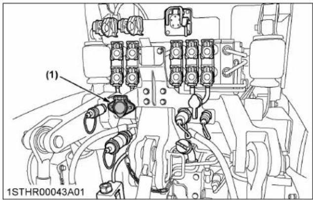
(1) Trailer electrical outlet
Function of each terminal in trailer electrical outlet
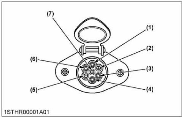
| Terminal Function | |
| (1) Ground | |
| (2) | Tail lightSide marker lightParking light |
| (3) Turn signal light (LH) | |
| (4) Brake stop light | |
| (5) Turn signal light (RH) | |
| (6) Registration plate light | |
| (7) — | |
2. ISOBUS socket (Premium and Premium KVT models only)
When an implement conforming to the ISO Standard 11783 guidelines is connected, various implement settings can be made through the K-monitor.
This means there is no need to add any controller and another monitor for the implement in question in the cabin.
Example: when equipped with a traveling speed-interlocked fertilizer applicator:
The K-monitor serves to enter the type of fertilizer, fertilizer application rate per area and other information.
Once the operation gets started, the implement adjusts itself for spray volume in response to the traveling speed and improves the performance.
What's more, the optional GPS function may be used together to navigate the tractor's traveling route. In doing so, uneven and redundant spraying can be prevented.
Read the operator's manual provided by the implement manufacturer and observe all safety messages in the manual and on the implement prior to use.

(1) ISOBUS socket (A) "PUSH"
3. Electrical outlet socket

(1) 3-terminal accessory electrical outlet
(A) Terminal: through the ACC position of the key switch (5 A)
(B) Terminal: through the battery direct (25 A)
(C) Terminal: ground
NOTE :
- The total combined current of both (A) terminals is 5 A.
Loader electrical outlet

(1) Electric connector for loader control device

(1) Loader electrical outlet
NOTE :
- Please refer to front loader operator's manual for details regarding the electric wiring connection.
4. ISOBUS monitor socket (Premium and Premium KVT models only)
An implement monitor meeting ISO Standard 11783 may be connected to the socket.

(1) ISOBUS monitor socket
5. Signal socket according to ISO standard 11786 (Premium and Premium KVT models only)
When connecting the connectors of implements meeting ISO standard 11786 to this socket, the following signals will be transmitted from the tractor to the implement.
Based on the transmitted signals, the tractor can control implement operations including stopping, operation restart, adjustment of dispersal amount (fertilizer, for example) and others.
NOTE :
- Implement side default settings are required to adjust the dispersal amount and so on.
Signals from the signal socket
| No. | Output signals Remarks | |
| 1 | Actual traveling speed | Operation with GPS mount-ed |
| 2 | Travel speed | Speed calculated from engine rpm and so on |
| 3 | Rear PTO rpm | |
| 4 | Operating or halted | When raising lift arm:operation haltedWhen lowering lift arm:operating |
| 5 | Rear 3-point hitch position | Lift arm height displayed by voltage |
| 6 | Power supply (5 A) | |
| 7 | Ground |

(1) Signal socket
6. Cigarette lighter
Push the lighter knob down to activate, with the key switch in the "ON" or "ACC" positions.
Lighter will move up when ready to use.

(1) Cigarette lighter
NOTE :
- An electrical consumer with a requirement for maximum 120 watts can be connected to the cigarette lighter.
INSTALLING THE IMPLEMENT CONTROL BOX
- Make a slit into the corner cover. Introduce the implement control cable and hydraulic hose through this slit into the CAB.

(1) Corner cover
- Remove the plugs in inner roof, and cut off the hatched zone of the rear pillar cover with a utility knife. Attach the control box stay with internal nuts.

(1) Plug
(2) Pillar cover
(3) M6 nuts
BEACON LIGHT
- Beacon light switch
a. Turn on the key switch and press the beacon light switch. Then the beacon light and indicator of switch will be activated.
b. Press the switch once more, and turn off the light and the indicator.
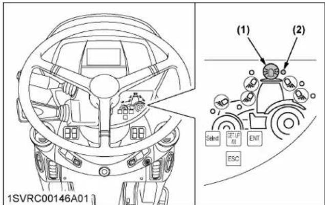
(1) Beacon light switch
(2) Indicator

(1) Beacon light (if equipped)
MAINTENANCE
SERVICE INTERVALS
| Interval Items | Ref. page | |||||
| A | initial 5, 10, 25 and 50 Hr | Bar axle torque Tighten 245 | ||||
| B | initial 50 Hr | Engine oil Change 245 | ||||
| Engine oil filter Replace 245 | ||||||
| Fan belt Adjust 245 | ||||||
| Transmission oil filter | Replace 245 | |||||
| C | every 50 Hr | Neutral circuit Check | 245 | |||
| Wheel bolt torque Check 249 | ||||||
| Tie-rod dust cover Check 249 | *1 | |||||
| Air brake Check 250 | ||||||
| D | every 100 Hr | Air cleaner primary element | Clean | 250 | *2 | |
| Greasing | — | 251 | ||||
| Brake pedal | Adjust 252 | |||||
| Parking brake lever Adjust 253 | *1 | |||||
| Battery condition | Check 253 | |||||
| Front PTO oil | Check 255 | |||||
| E | every 200 Hr | Fuel tank water | Drain 255 | |||
| Toe-in | Adjust 256 | |||||
| Inner air filter | Clean | 256 | ||||
| Fresh air filter | Clean | 256 | ||||
| F | every 250 Hr | Pre-fuel filter | Clean | 257 | ||
| Fuel filter | Replace 258 | |||||
| Fuel line | Check 258 | |||||
| G | every 400 Hr | Fan belt Adjust 259 | ||||
| Water separator Clean 260 | ||||||
| Fuel solenoid pump Clean 261 | ||||||
| H | initial 500 Hr | Transmission fluid | Change 261 | |||
| Rear axle case oil | Change 261 | |||||
| Transmission oil filter | Replace 261 | |||||
| I | every 500 Hr | Engine oil Change 262 | ||||
| Engine oil filter Replace 262 | ||||||
| Hydraulic oil filter (suction side) | Replace 262 | |||||
| Hydraulic oil filter (return side) | Replace 264 | |||||
(Continued)
| Interval Items | Ref. page | |||||
| I | every 500 Hr | Power steering oil filter | Replace 264 | |||
| Radiator hose and clamp | Check | 265 | ||||
| Intake air line | Check | 266 | ||||
| Brake hose | Check | 266 | *1 | |||
| Differential lock hose | Check | 266 | ||||
| Lift cylinder hose | Check | 267 | ||||
| Power steering oil line | Check | 267 | ||||
| Oil cooler line | Check | 267 | ||||
| Front suspension hose (front suspension type) | Check | 267 | *1 | |||
| Air conditioner pipes and hoses | Check | 268 | ||||
| Air conditioner drive belt | Check | 268 | ||||
| Front PTO oil | Change 269 | |||||
| J | every 1000 Hr | Transmission fluid | Change 269 | |||
| Transmission oil filter | Replace 270 | |||||
| Rear axle case oil | Change 271 | |||||
| Front differential case oil | Change 272 | |||||
| Front axle gear case oil | Change 272 | |||||
| Engine valve clearance | Adjust 273 | *1 | ||||
| K | every 1000 Hr or 1 year*3 | Air cleaner primary element and secondary element | Replace 273 | |||
| Exhaust manifold | Check | 273 | *1 | |||
| L | every 1500 Hr | Fuel injector nozzle tip | Clean | 273 | *1 | @ |
| DEF/AdBlue® injec-tor tip | Clean | 273 | *1 | |||
| DEF/AdBlue® line | Check | 273 | ||||
| Oil separator ele-ment | Replace 273 | @ | ||||
| Positive crankcase ventilation (PCV) valve (oil separator) | Check | 273 | *1 | @ | ||
| EGR cooler | Check Clean | 274 | *1 | @ | ||
(Continued)
| Interval Items | Ref. page | |||||
| L | every 1500 Hr | Accumulator (front suspension type) | Check 274 | *1 | ||
| M | every 2000 Hr or 2 years*4 | Cooling system Flush | 274 | |||
| Coolant Change 274 | ||||||
| N | every 3000 Hr | Turbocharger Check | 275 | *1 | @ | |
| Supply pump Check | 275 | *1 | ||||
| EGR system | Check Clean | 275 | *1 | @ | ||
| DEF/AdBlue® injec-tor | Check 275 | *1 | ||||
| DEF/AdBlue® pump filter | Replace 276 | |||||
| O | every 4000 Hr | DPF muffler Clean 276 | *1 | @ | ||
| P | every 1 year | DPF differential pressure sensor pipe | Check 276 | *1 | ||
| EGR pipe Check 276 | *1 | |||||
| Oil separator hose Check 276 | *1 | |||||
| Antifrost heater for oil separator (if equipped) | Check 276 | *1 | ||||
| CAB isolation cushion | Check 276 | |||||
| Q | every 2 years | DPF differential pressure sensor hose | Replace 276 | *1 | ||
| Boost sensor hose Replace 276 | *1 | |||||
| Fuel line Replace 276 | *1 | |||||
| R | every 3 years | Parking brake cable Replace 277 | *1 | |||
| S | every 4 years | Radiator hose and clamp | Replace 277 | |||
| Intake air line Replace 277 | *1 | |||||
| Oil separator hose Replace 277 | *1 | |||||
| Oil cooler line | Replace 277 | *1 | ||||
| Power steering oil line | Replace 277 | *1 | ||||
| Lift cylinder hose | Replace 277 | *1 | ||||
| Front suspension hose (front suspen-sion type) | Replace 277 | *1 | ||||
| Differential lock hose | Replace 277 | *1 | ||||
| Brake hose | Replace 277 | *1 | ||||
| Air conditioner pipes and hoses | Replace 277 | *1 | ||||
| T | Service as required | Fuel system Bleed 277 | ||||
| Brake system | Bleed 278 | |||||
| Fuse | Replace 279 | |||||
(Continued)
| Interval Items | Ref. page | |||||
| T | Service as required | Light bulb | Replace 282 | |||
| Head lamp Replace 282 | ||||||
| Lubricating point | — | 282 | ||||
| Washer liquid | Add | 282 | ||||
| Refrigerant (gas) | Check 282 | |||||
*1 Consult your local KUBOTA Dealer for this service.
*2 Air cleaner should be cleaned more often in dusty conditions than in normal conditions.
*3 Every 1000 hours or every 1 year, whichever comes first.
*4 Every 2000 hours or every 2 years, whichever comes first.
IMPORTANT :
- The items marked with @ are registered as emission related critical parts by KUBOTA in the U.S.EPA nonroad emission regulation. As the engine owner, you are responsible for the performance of the required maintenance on the engine according to the above instructions. See the Warranty Statement for details.
- When using biodiesel, be sure to check the maintenance requirements of biodiesel fuel as the intervals will change in some of the items.
MAINTENANCE ITEMS CHART
How to use the chart
-
The circles in this at-a-glance chart indicate the relevant points between the tractor's hour meter readings and the service intervals. Following these circles and the maintenance item group (A through S), keep up your tractor.
-
Details regarding maintenance items can be found in a different section.
(See SERVICE INTERVALS on page 230.)
Chart at a glance
| No. Locations | Capacities | Lubricants | ||||
| M7-132 M7 | -152 M7-172 | |||||
| 1 Fuel 330 L (87.2 U.S.gals.) | No.2-D S15 diesel fuelNo.1-D S15 diesel fuel if temperature is below -10 °C (14 F) | |||||
| 2 DEF/AdBlue ® | 38 L (10 U.S.gals.) | |||||
| 3 Coolant 24 L (6.3 U.S.gals.) Fresh clean soft water with antifreeze | ||||||
| 4 Washer liquid 2 L (2.1 U.S.qts.) Automobile washer liquid | ||||||
| 5 | Engine crankcase (with filter) | 22 L (5.8 U.S.gals.) | • Engine oil:API Service Classification | CJ-4 (DPF type engine) | ||
| Above 0 °C (32 F) 10W-30 | or 15W-40 | |||||
| Below 0 °C (32 F) 10W-30 | ||||||
| 6 Transmission case | Power shift model: 85 L(22.5 U.S.gals.)CVT model: 80 L (21.1 U.S.gals.) | KUBOTA UDT-HD fluid* (CANADA market: K4-Trans Hydraulic Oil) | ||||
| 7 Rear axle case oil 10 L (10.6 U.S.qts.) for each side | • KUBOTA 80W-90 gear lubricant HD or KHD (CANADA mar- ket: TRANSTEC 5 80W-90) | |||||
| 8 Front differential case oil 8.5 L (9.0 U.S.qts.) | ||||||
| 9 Front axle gear case oil 2.1 L (2.2 U.S.qts.) for each side | ||||||
| 10 | Front PTO case | 2.7 L (2.9 U.S.qts.) | • KUBOTA UDT-HD fluid* (CANADA market: K4-Trans Hy- draulic Oil) | |||
| 11 | Greasing | No. of greasing points | Capacity | Type of grease | ||
| Top link | 2 | Until grease overflows. | Multipurpose grease NLGI-2 or NLGI-1(GC-LB) | |||
| Lift rod | 4 | |||||
| Universal joint (front axle drive shaft) | 1 | |||||
| Front axle support | 2 | |||||
| Hydraulic lift cylinder pin | 4 | |||||
| Hydraulic lift arm shaft | 2 | |||||
| Parking brake shaft | 2 | |||||
| Front 3-point hitch (if equipped) | 7 | |||||
| Battery terminal | 2 | A small amount | ||||
NOTE :
- The product name of KUBOTA genuine UDT fluid may be different from that in the operator's manual depending on countries or territories. Consult your local KUBOTA Dealer for further details.
Engine oil
- The oil used in the engine should have an American Petroleum Institute (API) service classification and proper SAE engine oil according to the ambient temperatures shown in the previous table.
- Refer to the following table for the suitable API classification engine oil according to the diesel particulate filter (DPF) type engines and the fuel.
| Fuel used | Engine oil classification (API classification) |
| Oil class for engines with DPF | |
| Ultra Low Sulfur Fuel(<0.0015% (15 ppm)) | CJ-4 |
Fuel
• Use the ultra low sulfur diesel fuel only (below 0.0015% or 15 ppm) for these engines.
- Cetane number of 45 minimum. Cetane number greater than 50 is preferred, especially for temperatures below -20ircC (-4 ircF ) or elevations above 1500m (5000 ft).
- Diesel fuels specified to EN 590 or ASTM D975 are recommended.
- No.2-D is a distillate fuel of lower volatility for engines in industrial and heavy mobile service (SAE J313 JUN87).
DEF/AdBlue®:
The DEF/AdBlue ® , used as reducing agent of SCR, is a 32.5% urea aqueous solution.
The product is available at gas stations, truck stops and specialty shops. Be sure to use the genuine product only.
- Use exclusively DEF/AdBlue that complies with the requirements of ISO 22241-1.
Transmission oil and rear axle case oil:
The oil used to lubricate the transmission is also used as hydraulic fluid. To ensure proper operation of the hydraulic system and to complete lubrication of the transmission, it is important that a multi-grade transmission fluid is used in this system. We recommend the use of KUBOTA UDT, UDT-HD fluid or K4-Trans Hydraulic Oil for optimum protection and performance.
Consult your local KUBOTA Dealer for further details.
Do not mix different brands together.
Indicated capacities of water and oil are manufacturer's estimate.
1. Biodiesel fuel (BDF) B0-B20
B0-B20 Biodiesel fuels (BDF): mixed diesel fuels containing 20% or less biodiesel can be utilized under the following conditions.
IMPORTANT :
- Refueling and handling fuel should be done with caution in order to avoid contact with the fuel and spillage that could create a potential environmental or fire hazard. Wear appropriate protective equipment when refueling.
Applicable BDF:
- Blended diesel fuels containing 6% through 20% BDF (B6 - B20) which comply with American Society for Testing and Materials (ASTM) D7467 Standard, as revised, can be used without adversely affecting the performance and durability of the engine and fuel system components.
- Any mineral oil diesel fuel, if used, must conform to ASTM D975 (or the European EN590) Standard, as revised. B100 fuel used to make Biodiesel blended fuels must meet ASTM D6751 (or EN14214) Standard, as revised. The final blended fuel B20 must conform to ASTM D7467 Standard, as revised. Straight vegetable oil is not allowed in any blended fuel.
- Allowable blended fuel is mineral oil diesel fuel blended with B100 (meaning, 100% BDF). The blended fuel ratio shall be less than 20% B100 and 80% or more diesel fuel. The B100 source used for Biodiesel blends must be purchased from an accredited BQ-9000 marketer or producer. More information about qualified marketer(s) and producer(s) can be found at http://www.bq-9000.org.
Preparation:
- Before using BDF concentrations greater than B5, you are advised to replace the engine oil, engine oil filter and fuel filter with new oil and filters. Details regarding the replacement procedures can be found in a different section. (See Changing engine oil on page 262 and Replacing engine oil filter on page 262.)
Product warranty, emission and other precautions:
- The engine emission control system was certified according to current regulations based on the use of non-BDF. When using BDF, the owner is advised to check applicable local and federal emission regulations and comply with all of them.
- BDF may cause restricted or clogged fuel filters during cold weather conditions, resulting in the engine not operating properly.
- BDF encourages the growth of microorganisms which may cause degradation of the fuel. This in turn may cause fuel line corrosion or reduce fuel filter flow earlier than expected.
- BDF inherently absorbs moisture which may cause degradation of the fuel earlier than expected. To avoid this, drain the water separator and fuel filter port often.
- Do not use Biodiesel concentrations higher than 20% (namely, greater than B20). Engine performance and fuel consumption will be affected, and degradation of the fuel system components may occur.
- Do not readjust the engine fuel control system as this will violate emission control levels for which the equipment was approved.
- Compared with soybean-based and rapeseed-based feedstock, palm oil-based feedstock has a thicker consistency (that is, higher viscosity) at lower temperatures. Consequently, fuel filter performance may be reduced, particularly during cold weather conditions.
- The KUBOTA Warranty, as specified in the owner's warranty information guide, only covers defects in product materials and workmanship. Accordingly, any problems that may arise due to the use of poor quality fuels that fail to meet the above requirements, whether biodiesel or mineral oil based, are not covered by the KUBOTA Warranty.
Routine handling:
- Avoid spilling BDF onto painted surfaces as this may damage the finish.
If fuel is spilled immediately wipe clean and flush with soapy water to avoid permanent damage. - When using BDF, you are advised to maintain a full tank of fuel, especially overnight and during short term storage, to reduce condensation within the tank. Be sure to tighten the fuel cap after refueling to prevent moisture build up within the tank. Water in the biodiesel mixture will damage fuel filters and may damage engine components.
Maintenance requirements when using BDF B0 through B5:
Follow the recommended oil change intervals. (See MAINTENANCE on page 230.)
Extended oil change intervals may result in premature wear or engine damage.
Maintenance requirements when using BDF B6 through B20:
The maintenance intervals for fuel related parts changes.
See the following table for the new maintenance intervals.
| Items Interval Remarks | |||
| Pre-fuel filter Clean every 250 Hr | |||
| Fuel filter Replace every 250 Hr | |||
| Fuel hose | Check every 250 Hr | Replace if any deterioration (crack, hardening, scar or deformation) or damage occurred. | |
| Replace every 2 years Consult your local KU | BOTA Dealer for this service. | ||
Long term storage:
- BDF easily deteriorates due to oxygen, water, heat and foreign substances.
Do not store B6 through B20 longer than 1 month and B5 longer than 3 months.
- When using B6 through B20 and storing the machine longer than 1 month, drain the fuel from the tanks and replace with light mineral oil diesel fuel.
Subsequently, run the engine at least 30 minutes to remove all of the Biodiesel from the fuel lines.
- When using B5 fuel and storing machine longer than 3 months, drain the fuel from the tanks and replace with light mineral oil diesel fuel.
Subsequently, run the engine at least 30 minutes to remove all of the Biodiesel from the fuel lines.
PERIODIC SERVICE

WARNING
To avoid personal injury or death:
- Do not work under any hydraulically supported devices. They can settle, suddenly leak or be accidentally lowered. If necessary to work under the tractor or any machine elements for servicing or adjustments, securely support them with stands or suitable blocking beforehand.
WASTE DISPOSAL
- The improper disposal or burning of waste causes environmental pollution and can be punishable by your local laws and regulations.
- When draining fluids from the tractor, place a container underneath the drain port.
- Do not pour waste onto the ground, down a drain, or into any water source (such as rivers, streams, lakes, marshes, seas and oceans).
- Waste products such as used oil, fuel, coolant, hydraulic fluid, urea aqueous solution (DEF/AdBlue®), refrigerant, solvent, filters, rubber, batteries and harmful substances, can harm the environment, people, pets and wildlife.
Please dispose properly.
See your local recycling center or KUBOTA Dealer to learn how to recycle or get rid of waste products.
HOW TO OPEN THE HOOD

WARNING
To avoid personal injury or death from contact with moving parts:
- Never open the hood or engine side cover while the engine is running.
- Do not touch muffler or exhaust pipes while they are hot. Severe burns could result.
- While unlocking the hood, hold the hood with other hand.
1. Hood
- To open the hood, hold the hood and pull the release lever.
The hood will unlock and lifts a little.
- Open the hood fully with both hands.

(1) Release lever
(A) "PULL"
(2) Hood
NOTE :
- To close the hood, pull down on the strap and push the hood into position using both hands.
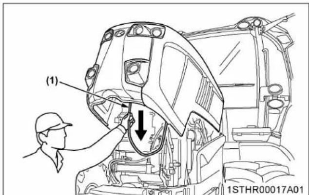
(1) Strap
2. Side cover
Remove the bolts as follows.

(1) Side cover
(2) Bolt
DAILY CHECK
For your own safety and maximum service life of the machine, make a thorough daily inspection before operating the machine to start the engine.

WARNING
To avoid personal injury or death:
Take the following precautions when checking the tractor.
- Park the machine on firm and level ground.
- Set the parking brake.
- Lower the implement to the ground.
- Release all residual pressure of the hydraulic system.
- Stop the engine and remove the key.
- Lower the front suspension to the lowest position (front suspension type only).
1. Walk around inspection
Look around and under the tractor for items such as loose bolts, trash build-up, oil or coolant leaks, broken or worn parts.
2. Checking and refueling

WARNING
To avoid personal injury or death:
- Never use fire.
- Do not smoke while refueling.
- Be sure to stop the engine and remove the key before refueling.
- Use properly grounded fueling systems. Make sure that there is no static discharge.
- Be sure to close the fuel tank cap after refueling.
To avoid allergic skin reaction:
- Wash hands immediately after contact with diesel fuel.
- Check the amount of fuel by looking at the fuel gauge.
- When the fuel warning indicator lights up, it is time to add fuel.
- Before removing the fuel cap, clean dirt away from the caps and the tank openings.

(1) Fuel tank cap
Fuel tank capacity 330 L (87.2 U.S.gals.)
IMPORTANT :
- Be sure to use ultra low sulfur fuel (S15).
- Do not permit dirt or trash to get into the fuel system.
- Be careful not to let the fuel tank become empty. Otherwise, air will enter the fuel system, necessitating bleeding before the next engine start.
- If the engine runs out of fuel and stalls, engine components may become damaged.
- Be careful not to spill during refueling. If a spill occurs wipe it off at once or it may cause a fire.
• To prevent condensation (water) accumulation in the fuel tank, fill the tank before parking overnight.
3. Checking antifrost heater for oil separator (if equipped)

WARNING
To avoid personal injury or death:
- Because there are rotating parts like the fan, and so on, near the inspection position, keep the engine off during inspection.
When operating tractors with antifrost heaters for oil separator in cold regions (below the freezing point: 0 °C / 32 °F), carry out inspection by using the following procedure before starting work:
- Turn the key switch to "ON", and 1 minute later, inspect by touch whether the heater is working. If the heater is working, its temperature will rise to roughly 70ircC (158 F), so you will be able to feel its warmth.
- If the heater is not warm, it is not working. In this case, contact your local KUBOTA Dealer without starting the engine.

natural_image
Mechanical assembly diagram showing interconnected pipes and components (no readable text or symbols)(1) Heater
NOTE :
- Refer to the following figure for the heater inspection position.

(1) Heater
4. Checking DEF/AdBlue ® level and adding fluid

WARNING
To avoid personal injury or death:
- Before adding DEF/AdBlue ® , stop the engine. When adding the fluid, preferably wear protective goggles and rubber gloves.
NOTE :
- The DEF/AdBlue ® tank cap is blue. Be careful not to confuse it with the fuel tank cap.
Look at the DEF/AdBlue ® gauge on the instrument panel to see how much fluid remains. If the level is too low, add DEF/AdBlue ® as required.
Before removing the DEF/AdBlue ® cap, clean dirt away from the caps and the tank openings.
If the fluid runs short or poor-quality fluid is added, a warning sign appears on the instrument panel. If this warning is ignored and the operation continues, the engine output will be limited.
(See Warning indication and countermeasures on page 117.)
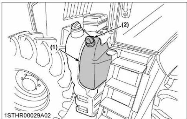
(1) DEF/AdBlue ® tank
(2) Tank cap (blue)

(1) DEF/AdBlue ® gauge
(2) DEF/AdBlue® warning indicator
(3) DEF/AdBlue ® system warning indicator

(1) Drain plug
Tank capacity 38 L (10 U.S.gals.)
IMPORTANT :
- Use exclusively DEF that complies with the requirements of ISO 22241-1.
- Do not put any type of fluid other than DEF in the DEF tank.
- If any fluid other than the specified DEF is put into the tank, the SCR system may get damaged.
- If contamination such as above has occurred, inspection of the SCR system by your local dealer is necessary. Repair or overhaul as needed.
- When refilling the DEF tank, never do the following or SCR system malfunction will result:
- Do not dilute DEF with water.
- Do not mix or add gasoline, diesel, oils or other products into the DEF.
- When removing the DEF tank cap, be careful not to allow mud or any debris into the DEF tank. Otherwise, the DEF filter may become clogged or the DEF quality degraded, possibly resulting in a SCR system failure.
- If DEF runs short, the engine speed and loading capacity are limited. Do not keep running the engine without replenishing it with this fluid. Otherwise the engine will stay at idle.
- Do not overfill DEF tank or fill while the machine is in use. DEF may leak out of the breather port and become frozen. If freeze-up occurs, sensor damage may result.
- Do not stand on or place anything on the DEF tank as the tank, piping and sensor damage may result.
- It is normal for the SCR system to continue to run to complete a DEF piping purge cycle process even after the starter switch has been set to the "OFF" position.
When the battery or main electrical connections are disconnected for inspection, repair or long term storage, the operator should wait several minutes until the system has completed this process.
- When the engine is stopped, it is normal to hear some continued related noise from the SCR system such as DEF tank, or DEF pump. This is a normal function of the DEF piping purge process.
- If DEF splashes on the machine body or frame, it may result in rust. Wipe off the spilled fluid and rinse the affected spot(s).
- Do not tamper with the exhaust pipe and muffler. Do not relocate the DEF tank, either. Such action may adversely affect the exhaust gas purifying performance.
- When DEF stuck on the filler port has dried up, white powder may be found. This is nothing
unusual. Wipe it off carefully so as not to allow it into the DEF tank.
5. Checking pneumatic brake pressure (if equipped)
- Check to see if the pressure in the air tank has reached the specified level. It is normal when the pneumatic pressure gauge is extended to the right.
- If the pressure drops too low, the warning indicator lights up on the instrument panel. Do not run the tractor with this indicator on.

(1) Pneumatic pressure gauge
(2) Trailer brake warning indicator
6. Checking water separator
- When water accumulates in the water separator, the water separator indicator will be displayed on the LCD monitor and a warning buzzer will sound.
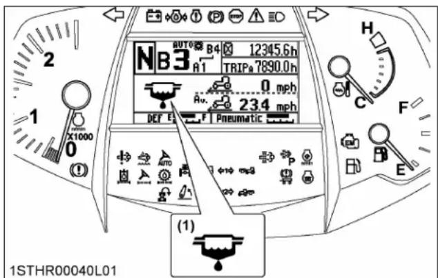
(1) Water separator indicator
- When this happens, drain the water as follows.
Draining the water from the water separator
- Loosen the drain plug by several turns.
- Allow water to drain. When no more water comes out and fuel starts to flow out, retighten the drain plug.
3. Bleed the fuel system.
(See SERVICE AS REQUIRED on page 277.)

(1) Cup
(A) "FUEL"
(2) Drain plug
(B) "WATER"
NOTE :
- If water drainage is carried out according to the following procedure, air will be prevented from entering the fuel system, and bleeding the fuel system will not be necessary. If the following procedure is carried out, we recommend placing a sign reading "Engine operation strictly forbidden due to ongoing maintenance" or similar on the steering wheel for safety purposes.
- Keep the key switch in the "ON" position (engine will not start up), and pressurize the fuel system with the fuel feed pump.
- In this status, loosen the drain plug slightly and gradually drain water.
IMPORTANT :
- If water is drawn through to the fuel pump, extensive damage will occur.
7. Checking engine oil level

WARNING
To avoid personal injury or death:
- Be sure to stop the engine before checking the oil level.
- Park the machine on a flat surface.
- Check engine oil before starting the engine or 5 minutes or more after the engine has stopped.
- To check the oil level, draw out the dipstick, wipe it clean, replace it, and draw it out again. Check to see that the oil level lies between the 2 notches. If the level is too low, add new oil to the prescribed level at the oil inlet.
(See LUBRICANTS, FUEL AND COOLANT on page 233.)

(1) Oil inlet
(2) Dipstick
(A) "Oil level is acceptable within this range."
IMPORTANT :
- When using an oil of different manufacturer or viscosity from the previous one, remove all of the old oil.
Never mix 2 different types of oil.
- If the oil level is low, do not run the engine.
NOTE :
- At times, a small amount of fuel, which is used to regenerate the DPF, may get mixed with the engine oil and the engine oil may increase in volume.
8. Checking transmission fluid level
- Check the transmission fluid level under the following conditions:
a. Park the machine on a flat surface.
b. Lower the rear 3-point hitch and front end loader (if equipped).
c. Raise the front 3-point hitch. (if equipped).
d. Disconnect all remote control valve hoses.
e. Shut off engine and wait for 10 minutes.
- Check to see that the oil level lies between the 2 lines of the sight glass.
If the level is too low, add new oil to the prescribed level at the oil inlet.
(See LUBRICANTS, FUEL AND COOLANT on page 233.)
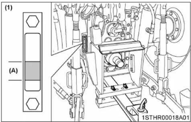
(1) Sight glass (A) "Oil level is acceptable within this range."

(1) Oil inlet
IMPORTANT :
• If oil level is low, do not run engine.
- More transmission oil may be needed for operations with many types of large implements equipped with hydraulic cylinder.
Consult your local KUBOTA Dealer for more details.
9. Checking coolant level
WARNING
To avoid personal injury or death:
- Do not remove the radiator cap while the coolant is hot. When cool, slowly rotate the cap to the first stop and allow sufficient time for excess pressure to escape before removing the cap completely.
- Check to see that the coolant level is between the [MAX] and [MIN] marks of recovery tank.
- When the coolant level drops due to evaporation, add soft water only up to the max level. In case of leakage, add antifreeze and soft water in the specified mixing ratio up to the max level. (See Flushing cooling system and changing coolant on page 274.)
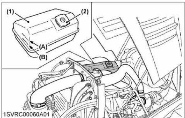
(1) Recovery tank
(A) [MAX]
(2) Radiator cap
(B) [MIN]
IMPORTANT :
- If the radiator cap has to be removed, follow the previous caution and securely retighten the cap.
- Use clean, fresh soft water and antifreeze to fill the radiator.
- If coolant should leak, consult your local KUBOTA Dealer.
10. Cleaning grill, radiator, and cooler
WARNING
To avoid personal injury or death:
- Be sure to stop the engine before checking and cleaning.
- The condenser and receiver become hot while the air conditioner is running. Before checking or cleaning them, wait long enough until they cool down.
Radiator and cooler locations

(1) Radiator
(2) Intercooler
(3) Oil cooler
(4) Fuel cooler
(5) Air conditioner condenser
(6) Front PTO cooler (if equipped)
(7) Latch
Opening the cooler and condenser pack
- Undo the latches on both sides.
- Hold the handle and open the cooler and condenser pack forward.
- When the pack has been closed, be sure to lock the latches on both sides.
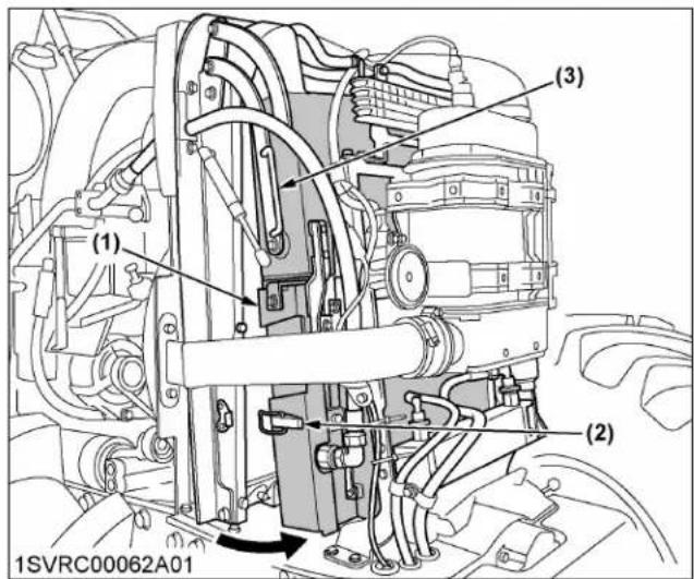
(1) Cooler and condenser pack
(2) Latch
(3) Handle
Cleaning
-
Check front grill to be sure it is clean from debris.
-
Check radiator, air conditioner condenser, intercooler, oil cooler, fuel cooler, and front PTO cooler to be sure they are clean from debris.
- Use compressed air, low compression, and wand type air nozzle to blow debris clear of the cooling pack. Wear eye protection during this operation.

(1) Radiator
(2) Intercooler
(3) Oil cooler
(4) Fuel cooler
(5) Air conditioner condenser
(6) Front PTO cooler (if equipped)
IMPORTANT :
- Grill must be clean from debris to prevent engine from overheating and to allow good air intake for air cleaner.
11. Checking DPF/SCR muffler

WARNING
To avoid personal injury or death:
- Before checking or cleaning the DPF/SCR muffler, stop the engine and wait until it cools down enough.
Check the DPF/SCR muffler and its surroundings for accumulation of anything flammable.
Otherwise a fire may result.

(1) DPF muffler
(2) SCR muffler
12. Checking brake pedal

WARNING
To avoid personal injury or death:
- Make sure that the brake pedals have equal adjustments when being locked together. Incorrect or unequal brake pedal adjustments can cause the tractor to swerve or roll-over.
- Inspect the brake pedals for free travel and smooth operation.
- Adjust if incorrect measurement is found. (See Adjusting brake pedal on page 252.)
13. Checking parking brake
Pull the parking brake lever to apply the brakes. With the key switch at "ON" position, the parking brake warning indicator on the instrument panel lights up.
To release the brakes, push in the button at the tip of the parking brake lever and tilt down the lever.
NOTE :
• Make sure the lamp on the instrument panel goes off when parking brake lever is down.

(1) Parking brake lever
(2) Release button
(A) "PULL"
(B) "RELEASE"
14. Checking gauges, meter and Easy Checker TM
- Inspect the instrument panel for broken gauge(s), meter(s) and Easy Checker™ indicators.
- Replace if broken.
15. Checking headlight, turn signal light, hazard light, and so on
- Inspect the lights for broken bulbs and lenses.
- Replace if broken.
16. Checking seat belt
- Always check the condition of the seat belt attaching hardware before operating the tractor.
- Replace if damaged.
17. Checking movable parts
If any of the movable parts, such as levers and pedals, are not moving smoothly because of rust or sticky material, do not attempt to force them into motion.
In the above case, remove the rust or the sticky material and apply oil or grease to the relevant spot.
Otherwise, the machine may be damaged.
INITIAL 5, 10, 25, AND 50 HOURS
With a new machine, be sure to do the following servicing after the first 5, 10, 25, and 50 operating hours.
1. Tightening bar axle torque

WARNING
To avoid personal injury or death:
- Never operate tractor with loose wheel bolts. Wheel bolts are critical and require retightening.
- Retighten the bolts after operating 5 hours, 10 hours, 25 hours, and 50 hours, as follows.
10 bolts fix type
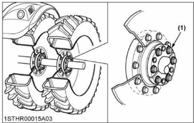
With a new machine, be sure to do the following servicing after the first 50 operating hours.
1. Changing engine oil
(See Changing engine oil on page 262.)
2. Replacing engine oil filter
(See Replacing engine oil filter on page 262.)
4. Replacing transmission oil filter
(See Replacing transmission oil filter on page 270.)
EVERY 50 HOURS
1. Checking neutral circuit

WARNING
To avoid personal injury or death:
- Do not allow anyone near the tractor while testing.
- If the tractor does not pass the test, do not operate the tractor.
1.1 Preparation before testing
- Place all control levers in the "NEUTRAL" position.
- Set the parking brake, stop the engine and lower all implements.
1.2 Testing engine start system

(1) Shuttle lever
(2) Clutch pedal
(3) Liquid crystal display
- Follow the instructions about parking the tractor. (See PARKING THE TRACTOR on page 15.)
- Sit on the operator's seat.
- Depress the clutch pedal fully.
- Turn the key to "START" position.
- The engine must crank.
- If it does not crank, consult your local Kubota Dealer for this service.
1.3 Testing transmission (neutral) control
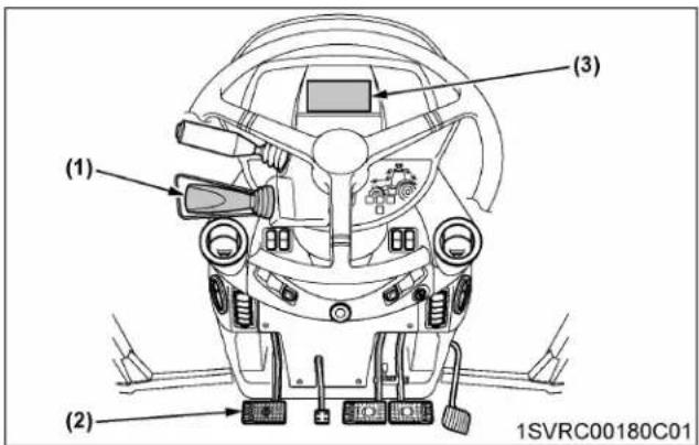
(1) Shuttle lever
(2) Clutch pedal
(3) Liquid crystal display
- Follow the instructions about parking the tractor. (See PARKING THE TRACTOR on page 15.)
- Sit on the operator's seat.
- Depress the clutch pedal fully.
- Start the engine.
- Check to see if the shuttle shift is held in their "NEUTRAL" position.
- If not, consult your local Kubota Dealer for this service.
1.4 Testing hydraulic up/down (lock) control
Standard, Deluxe models

(1) Parking brake lever
(2) 3-P quick raise and lower switch
(3) Depth control dial (hydraulic dial)
(4) 3-point hitch lock button
Premium, Premium KVT models

(1) Parking brake lever
(2) 3-P quick raise and lower switch
(3) Depth control dial (hydraulic dial)
(4) 3-point hitch lock button
- Follow the instructions about parking the tractor (See PARKING THE TRACTOR on page 15.)
- Sit on the operator's seat.
- Depress the clutch pedal fully.
- Start the engine.
- Press the 3-point hitch lock button to get the hitch locked (the indicator in the switch lights up).
- Make sure that the implement cannot be raised or lowered even with the 3-point quick raise and lower switch or the depth control dial (hydraulic dial).
- Release the 3-point hitch lock button to get the hitch unlocked (the indicator in the switch goes off).
- Move the 3-point quick raise and lower switch or the depth control dial (hydraulic dial), and make sure the implement is raised and lowered.
- If any trouble occurs, consult your local KUBOTA Dealer for this service.
1.5 Testing remote hydraulic control (Premium and Premium KVT models)

(1) Parking brake lever
(2) Remote control valve switch
(3) Remote control valve lock button
- Follow the instructions about parking the tractor. (See PARKING THE TRACTOR on page 15.)
- Sit on the operator's seat.
- Depress the clutch pedal fully.
- Start the engine.
- Press the remote control valve lock button to get the valve locked (the indicator in the switch lights up).
- Move the implement-linked remote control valve switch, and make sure the implement is not moved.
- Press the remote control valve lock button to get the valve unlocked (the indicator in the switch goes off).
- Move the remote control valve switch, and make sure the implement is moved.
- If any trouble occurs, consult your local KUBOTA Dealer for this service.
1.6 Testing external rear PTO switch control
Standard, Deluxe models

(1) Parking brake lever
(2) PTO operation mode selection lever
(3) PTO speed selection lever
Premium, Premium KVT models

(1) Parking brake lever
(2) PTO operation mode selection lever
(3) PTO speed selection lever

(1) External switch for rear PTO
- Follow the instructions about parking the tractor. (See PARKING THE TRACTOR on page 15.)
- Make sure the PTO drive shaft is disconnected from attached implement.
- Start the engine.
- Using the PTO operating mode selector lever and the PTO gear shift lever, select the PTO 540 or 1000 rpm.
- Press one of the external PTO clutch control switches on the right and left fenders and release your hand from the switch within 3 seconds, and make sure the PTO rotation is turned off.
- Hold down the switch longer than 3 seconds to keep on the PTO rotation. Confirm that a warning buzzer sounds for 10 seconds or so when entering continuous rotation mode.
- Press one of the external OFF switch on the right and left fenders, and make sure the PTO rotation has stopped.
- If any trouble occurs, consult your local KUBOTA Dealer for this service.
1.7 Testing operator presence control (OPC) system of PTO

WARNING
To avoid personal injury or death:
- Before checking the PTO OPC, make sure that the PTO drive shaft is disconnected from the tractor.
- If the buzzer does not sound during the PTO OPC check procedure, shut off the engine and consult your local KUBOTA Dealer for immediate servicing of the PTO OPC.
- The unit should not be operated until servicing is completed.
Do this test for the front PTO and rear PTO individually.
Standard, Deluxe models

(1) Parking brake lever
(2) Front PTO clutch control switch
(3) Rear PTO clutch control switch
(4) PTO operation mode selection lever
(5) PTO speed selection lever
Premium, Premium KVT models

(1) Parking brake lever
(2) Front PTO clutch control switch
(3) Rear PTO clutch control switch
(4) PTO operation mode selection lever
(5) PTO speed selection lever

(1) Parking brake OPC indicator
- Follow the instructions about parking the tractor. (See PARKING THE TRACTOR on page 15.)
-
Sit on the operator's seat.
-
Make sure the PTO drive shaft is disconnected from any attached implement.
- Start the engine.
- Check the following items.
a. While the tractor is stopped and PTO is rotating, standing up from the operator's seat will stop the PTO within 1 second, and then the warning buzzer sounds for 1 second.
b. Even if the PTO clutch control switch or lever is engaged, the PTO will not start and the warning buzzer will sound 1 second if the operator is standing up from the operator's seat.
c. The PTO is rotating and the tractor is traveling at low speeds. Standing up from the operator's seat will set off the warning buzzer (the PTO will continue rotating).
d. When releasing the parking brake and when standing up from the operator's seat, check that the buzzer sounds and that the parking brake OPC indicator appears on the LCD monitor.
- If any trouble occurs, consult your local KUBOTA Dealer.
1.8 Testing operator presence control (OPC) system of shuttle lever (Standard, Premium models)

(1) Shuttle lever
(2) Clutch pedal
(3) Liquid crystal display
- Follow the instructions about parking the tractor. (See PARKING THE TRACTOR on page 15.)
- Sit on the operator's seat.
- After starting the engine, release the clutch pedal.
- Shift the shuttle lever to the "FORWARD" or "REVERSE" position.
- Check on the LCD monitor that the shuttle shift returns automatically to the "NEUTRAL" position when you stand up.
-
After sitting down, step on the clutch pedal.
-
Check on the LCD monitor that the shuttle shift selected in step 4 (forward or reverse) is automatically selected.
-
If any trouble occurs, consult your local KUBOTA Dealer for this service.
1.9 Testing operator presence control (OPC) system of shuttle lever (Premium KVT model)

(1) Shuttle lever
(2) Clutch pedal
(3) Liquid crystal display
- Follow the instructions about parking the tractor. (See PARKING THE TRACTOR on page 15.)
- Sit on the operator's seat.
- After starting the engine, release the clutch pedal.
- Check on the LCD monitor that when you are standing, the gearshift will remain in "NEUTRAL" even if you try to shift gears with the shuttle lever to the "FORWARD" or "REVERSE" position.
- If any trouble occurs, consult your local KUBOTA Dealer for this service.
2. Checking wheel bolt torque

WARNING
To avoid personal injury or death:
- Never operate the tractor with a loose rim, wheel or axle.
- Any time bolts and nuts are loosened, retighten to the specified torque.
- Check all bolts and nuts frequently and keep them tight.
Check wheel bolts and nuts regularly, especially when new. If they are loose, tighten them as follows.
Flange type

(1) 540 N · m / 55.1 kgf · m / 398 ft · lbs
(2) 670 N m / 68.3 kgf m / 494 ft lbs
Bar type axle (10 bolts fix type)

Bar type axle (8 bolts fix type)

3. Checking tie-rod dust cover
Check to see that dust covers are not damaged. If dust covers are damaged, consult your local KUBOTA Dealer for this service.

(1) Dust cover
IMPORTANT :
- If dust covers are cracked, water and dust can cause premature wear of the tie-rod.
4. Checking air brake for trailer (if equipped)
Discharging condensation (water) from the air tank.
- Push in the valve pin at the bottom of the air tank and check if there is a pool of condensation inside.

WARNING
To avoid personal injury or death:
- When discharging condensation (water) from the air tank, wear protective goggles to guard your eyes against sand and dust stirred up.
- Before doing the servicing, lower the pressure in the air tank first.
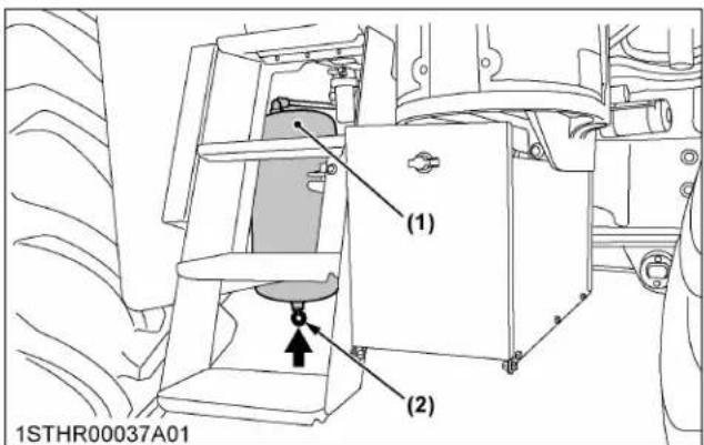
(1) Air tank
(2) Valve pin
Inspecting the air connector
- Check the sealing for damage and other abnormalities.
Damaged sealing should be replaced in order to avoid air leaks.
When not in use, keep the cap tight in position.
Check the following parts as well :
• Compressor drive belt for damage
- Compressor itself for oil leak
- Hoses for damage
EVERY 100 HOURS
1. Cleaning air cleaner primary element
- Unlatch and remove the housing service cover.
- Push down on the service handle to tilt the primary element to a 5irc angle. This will loosen the seal.
- Then, pull out on the service handle to remove the primary element from the housing.
- Clean the primary element :
When dry dust adheres to the element, blow compressed air from the inside, turning the element.
Pressure of compressed air must be under 205 kPa (2.1 kgf/cm², 30 psi).
- Inspect the element :
Visually check for cuts, tears or indentations on the sealing surfaces and the element before installation. If any damage is visible, do not install.
- Replace air cleaner primary element :
Once every 1000 hours or yearly, whichever comes first.
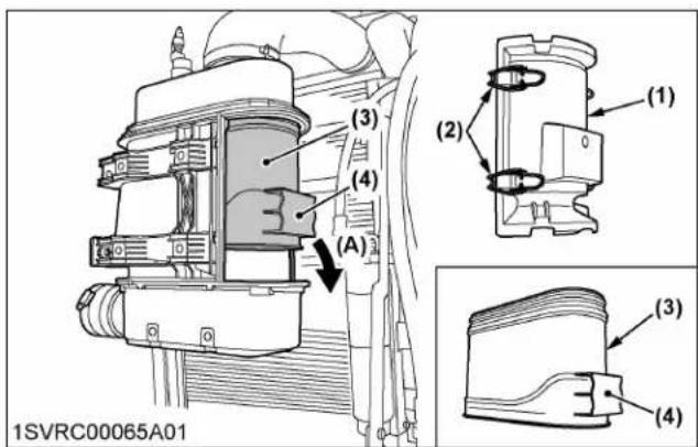
(1) Housing service cover
(A) "PUSH DOWN"
(2) Latch
(3) Primary element
(4) Service handle
NOTE :
- If the housing service cover doesn't fit, remove and recheck the primary element position. The cover will be difficult to install if the element isn't installed correctly.
1.1 Cleaning pre-cleaner tubes
-
Check to see if the pre-cleaner tubes are blocked with dust.
-
To clean the pre-cleaner tubes, remove the housing service cover and leave the element installed (to prevent dust from entering the air induction outlet). Use a low volume of compressed air to gently blow out the separator tubes.
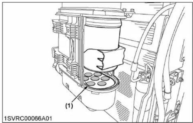
(1) Pre-cleaner tubes
IMPORTANT :
• The air cleaner uses a dry element, so never apply oil.
- Do not run the engine with filter element removed.
- Do not touch the secondary element except in cases where replacing is required.
1.2 Replacing secondary element
The secondary element should be replaced every 1000 hours or yearly, whichever comes first.
- To remove the secondary element, use the plastic handle on the face of the secondary element. Pull the element toward the center of the housing and remove it. Ensure that the outlet tube sealing area is clean and undamaged.

(1) Plastic handle
(2) Secondary element
2. Lubricating grease fittings
Apply a small amount of multipurpose grease to the following points every 100 hours.
If you have been operating the machine in extremely wet and muddy conditions, lubricate the grease fittings more often.

(1) Grease fitting (front axle support)
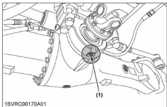
(1) Grease fitting (front axle support)

(1) Grease fitting (front axle drive shaft)
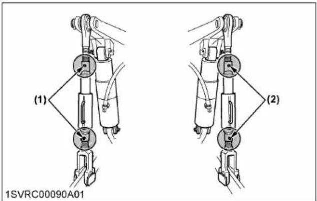
(1) Grease fitting (lifting rod) - LH
(2) Grease fitting (lifting rod) - RH

(1) Grease fitting (hydraulic lift cylinders pin)
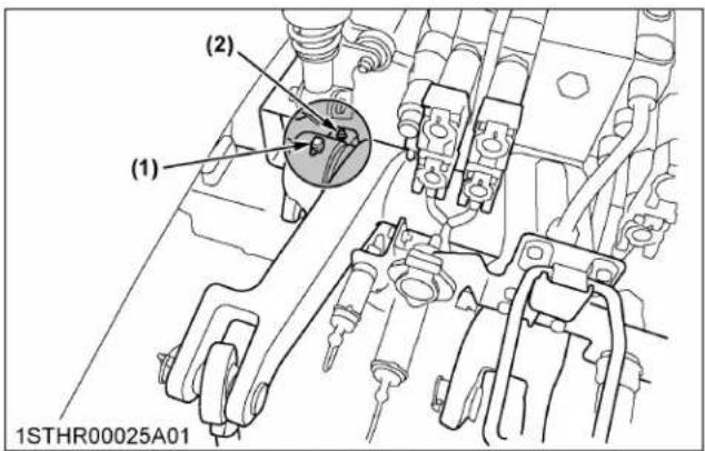
(1) Grease fitting (hydraulic lift arm shaft) - both sides
(2) Grease fitting (parking brake shaft) - both sides

(1) Battery terminal
Front 3-point hitch

(1) Grease fitting (hydraulic lift cylinders pin)
(2) Grease fitting (top link)
(3) Grease fitting (swing arm support)
3. Adjusting brake pedal
WARNING
To avoid personal injury or death:
- Stop the engine and chock the wheels before checking brake pedal.
• To prevent uneven braking, the specification must be within the recommended limit. If found out of the specifications, contact your local KUBOTA Dealer for adjusting the brakes.
3.1 Checking brake pedal free travel
Without trailer brake
| Proper brake pedal free travel | 3 to 7 mm (0.1 to 0.3 in.) on the pedal |
| Keep the free travel in the right and left brake pedals equal. |
With trailer brake (if equipped)
| Proper brake pedal free travel | 12 to 18 mm (0.47 to 0.71 in.) on the pedal |
| Keep the free travel in the right and left brake pedals equal. |
- Set the parking brake.
- Slightly depress the brake pedals and measure free travel at the top of pedal stroke.
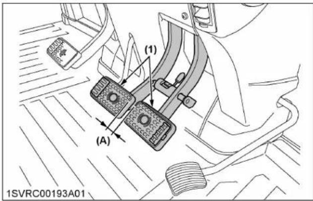
(1) Brake pedals (A) "FREE TRAVEL"
NOTE :
- Brake pedals should be equal when depressed.
3.2 Checking brake pedal stroke
Pedal stroke Less than 100 mm (3.9 in.) at each pedal
- Disengage the brake pedal lock.
- Depress the brake pedal several times.
- Step on the right-hand pedal and measure the level difference (pedal stroke) between this pedal and the left-hand pedal.
- Do the same for the left-hand pedal.

(1) Brake pedal (LH)
(2) Brake pedal (RH)
(3) Brake pedal lock
3.3 Checking equalizer working level (anti-imbalance device)
| Equalizer working level | Level difference of over 10 mm (0.4 in.) between both pedals |
- Gently step on both brake pedals at once.
- Further step on the right-hand pedal (the left-hand pedal slightly raises itself) and measure the level difference between the pedals.
- Do the same for the left-hand pedal.
4. Adjusting parking brake lever
Consult your local KUBOTA Dealer for this service.
5. Checking battery condition

DANGER
To avoid the possibility of battery explosion: For the refillable type battery, follow the instructions below.
- Do not use or charge the refillable type battery if the fluid level is below the [LOWER] (lower limit level) mark. Otherwise, battery component parts may prematurely deteriorate, which may shorten the battery's service life or cause an explosion. Check the fluid level regularly and add distilled water as required so that the fluid level is between the [UPPER] and [LOWER] levels.

WARNING
To avoid personal injury or death:
- Never remove the battery cap while the engine is running.
- Keep electrolyte away from eyes, hands and clothes. If you are spattered with it, wash it away completely with water immediately and get medical attention.
- Keep open sparks and flames away from the battery at all times. Hydrogen gas mixed with oxygen becomes very explosive.
- Wear eye protection and rubber gloves when working around the battery.
NOTE :
- The factory-installed battery is a non-refillable type.
Mishandling the battery shortens the service life and adds to maintenance costs.
The original battery is maintenance free, but needs some servicing.
If the battery is weak, the engine will be difficult to start and the lights will be dim. It is important to check the battery periodically.

(1) Battery
When using a boost-charged battery, it is necessary to recharge the battery as early as possible.
Failure to do this will shorten the battery's service life.
- Only switch off the charger once the battery has finished charging.
- When exchanging an old battery for a new one, use battery of equal specification shown in the following table.
| Volts (V) | Capacity (A.H) | Reserve capacity (min) | Cold cranking amps (EN) |
| 12 174 | (C20/EN) | 380 | 1400 (-18 °C or 0.4 F/EN) |
5.1 Charging the battery

WARNING
To avoid personal injury or death:
- When the battery is being activated, hydrogen and oxygen gases in the battery are extremely explosive. Keep the open sparks and flames away from the battery at all times, especially when charging the battery.
- When charging the battery, make sure that the vent caps are securely in place if equipped.
- When disconnecting the cable from the battery, start with the negative terminal first. When connecting the cable to the battery, start with the positive terminal first.
- Never check the battery charge by placing a metal object across the posts. Use a voltmeter or hydrometer.

(1) Battery
- To slow charge the battery, connect the battery positive terminal to the charger positive terminal and the negative to the negative, then recharge in the standard fashion.
- A boost charge is only for emergencies. It will partially charge the battery at a high rate and in a short time.
5.2 Directions for battery storage
- When storing the tractor for long periods of time, remove the battery from the tractor and store in a dry place out of direct sunlight.
- The battery self-discharges while it is stored. Recharge it once every 3 months in hot seasons and once every 6 months in cold seasons.
5.3 How to detach the battery
- Turn the battery switch to "OFF" and make sure that the battery switch indicator is off. If the indicator is lit, do not remove the battery cable until it turns off. It takes about 15 minutes to turn off.

(1) Battery switch
(A) "OFF"
(2) Indicator
(B) "ON"
- In order to prevent short-outs due to contact between the battery terminals (plus and minus) and the battery cover, use a rag to cover the terminals when removing or replacing the cover.
-
After removing the bolts, nuts, and battery cover as shown in the following figure, remove the battery.
-
When connecting the battery cable, confirm the cable and terminal plus and minus directions before connecting.
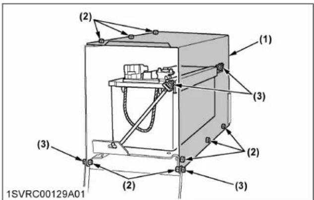
(1) Battery cover
(2) Bolt
(3) Nut
IMPORTANT :
- After turning the key switch to "OFF" and stopping the engine, the SCR system automatically begins to cool off the system and extract DEF/AdBlue® from the lines.
- Wait at least 15 minutes for the SCR system to complete this function before disconnecting the battery circuit for inspection, repair, or long-term storage of the battery or electrical components.
- Removing the battery before the completion of this function may cause system errors or damage to the system components.
- Even if the battery switch is turned to "OFF", the power supply will be sustained for about 15 minutes. Operating sound may continue to be heard from the SCR system (for example, from the DEF/AdBlue® tank or DEF/AdBlue® pump) after stopping the engine.
- This is the operating sound of the function that is cooling the SCR system and extracting DEF/AdBlue® from the lines, and not an abnormal sound.
6. Checking front PTO oil (if equipped)

WARNING
To avoid personal injury or death:
- Be sure to stop the engine before checking the front PTO oil.
- Remove the filling plug and check to see if the oil level is up to the plug hole. If low, add oil until it flows out of the filling plug hole.
(See LUBRICANTS, FUEL AND COOLANT on page 233.)
- Tighten up the filling plug in place.

(1) Front PTO
(2) Filling plug
EVERY 200 HOURS
1. Draining fuel tank water
- Unscrew the drain plug cover at the bottom of the fuel tank.
- Loosen the drain plug at the bottom of the fuel tank to let sediments, impurities and water out of the tank. Finally tighten up the plug.

(1) Fuel Tank
(2) Drain plug
(3) Plug cover
| Tightening torque | |
| Drain plug | 19 to 21 N·m / 1.9 to 2.1 kgf·m / 14.0 to 15.5 ft·lbs |
IMPORTANT :
- If the fuel contains impurities, such as water, drain the fuel tank at shorter intervals.
- Drain the fuel tank before operating the tractor after a long period of storage.
• The fuel tank is made of plastic. Be careful not to overtighten the bolts.
2. Adjusting toe-in

(A) Wheel-to-wheel distance at the rear
(B) Wheel-to-wheel distance at the front
(C) "FRONT"
| Proper toe-in 0 to 8 mm (0 to 0.31 in.) |
- Park the tractor on a flat surface.
- Turn the steering wheel so that the front wheels are in the straight-ahead position.
- Lower the implement, apply the parking brake and stop the engine.
- Measure the distance between the tire beads at the front of the tire, at hub height.
- Measure the distance between the tire beads at the rear of the tire, at hub height.
- The front distance should be shorter than the rear distance. If not, adjust the tie rod length.
2.1 Adjusting toe-in procedure
- Detach the snap ring.
- Loosen the tie-rod nut.
- Turn the tie-rod joint to adjust the rod length until the proper toe-in measurement is obtained.
- Retighten the tie-rod nut.
- Attach the snap ring of the tie-rod joint.
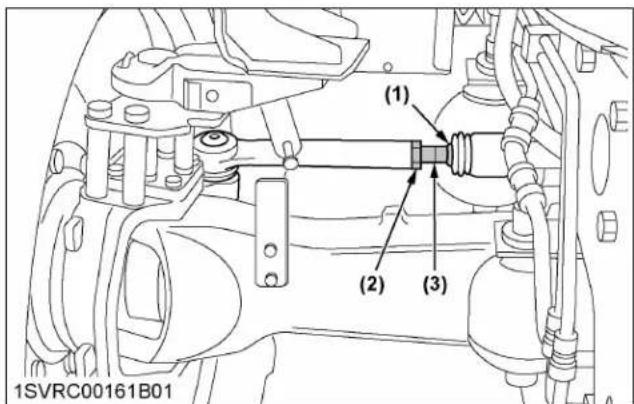
(1) Snap ring
(2) Tie-rod nut
(3) Tie-rod joint
3. Cleaning inner air filter
Remove the inner filter, and blow air from the direction opposite to the filter's normal air flow.
Pressure of compressed air must be under 205 kPa (2.1 kgf/cm 2 / 30 psi).
When reassembling, adjust the 4 clasps to fix the filter in it's correct position.
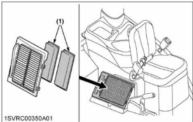
(1) Inner air filter
4. Cleaning fresh air filter
WARNING
To avoid personal injury or death:
- When removing and attaching the filter, apply the parking brake, stop the engine and remove the key.
-
Check the filter using the strong and stable ladder to stand on. Never check it while standing on a tire or fender.
-
Remove the knob bolts and pull out the filter.

(1) Fresh air filter
(A) Air inlet port
(2) Cover
(3) Knob bolt
NOTE :
• After cleaning, attach the filter and cover as shown in the previous illustration.
4.1 Cleaning the filter
Normal use
Blow air from the opposite direction to the filter's normal air flow.
Pressure of compressed air must be under 205 kPa (2.1 kgf/cm² / 30 psi).
IMPORTANT :
- Do not hit the filter. If the filter becomes deformed, dust may enter into the air-conditioner, which may cause damage and malfunction.

(A) "AIR CONDITIONER AIRFLOW"
NOTE :
- If the filter is very dirty: Dip the filter in lukewarm water with mild dishwashing detergent. Move it up and down as well as left and right to loosen dirt. Rinse the filter with clean water and let it air-dry.
IMPORTANT :
- Do not use gasoline, thinner or similar chemicals to clean the filter as damage to the filter may occur.
- It may also cause an unpleasant odor in the CAB next time the system is used.
EVERY 250 HOURS
1. Cleaning pre-fuel filter
This job should not be done in the field, but in a clean environment.
- Close the fuel shutoff-valve.
- Unscrew the retainer ring and remove the cup, and rinse the inside with kerosene.
- Remove the element and dip it in the kerosene to rinse.
- After cleaning, reassemble the pre-fuel filter, keeping out dust and dirt.
5. Bleed the fuel system.
(See Bleeding fuel system on page 277.)
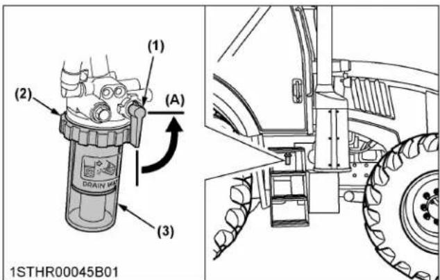
(1) Fuel shutoff-valve
(2) Retainer ring
(3) Cup
(A) "CLOSE"
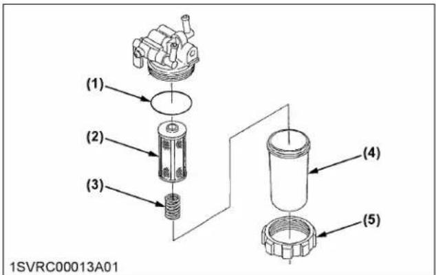
(1) O-ring
(2) Element
(3) Spring
(4) Cup
(5) Retainer ring
2. Replacing fuel filter
- Remove the fuel filter.
- Put a film of clean fuel on the rubber seal of the new filter.
- Tighten the filter quickly until it contacts the mounting surface.
Tighten the filter by hand an additional 1/2 turn only. - Bleed the fuel system.
(See Bleeding fuel system on page 277.)
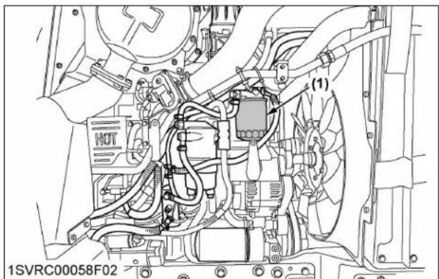
(1) Fuel filter
3. Checking fuel line
-
Replace if any deterioration (crack, hardening, scar or deformation) or damage occurred.
-
If the hoses and clamps are found to be worn or damaged, replace or repair them at once.

(1) Fuel lines
(2) Clamp bands

(1) Fuel lines
(2) Clamp bands
(3) Fuel cooler
NOTE :
- If the fuel line has been replaced, be sure to properly bleed the fuel system.
(See Bleeding fuel system on page 277.)
EVERY 400 HOURS
1. Checking fan belt tension

WARNING
To avoid personal injury or death:
- Be sure to stop the engine before checking the belt tension.
| Proper belt tension | A deflection of between 9 to 11 mm (0.35 to 0.43 in.) (for a new belt: 7 to 9 mm (0.28 to 0.35 in.)) when the belt is pressed (98 N / 10 kgf) in the middle of the span. |
The belt is of self-tension type and needs no readjustment. Check the belt tension in the following procedure. If the deflection is out of specification or the belt itself is found damaged, replace it with a new one.
- Stop the engine and remove the key.
- Press on the spot indicated in the following figure to measure the deflection.

(1) Fan belt (A) Check the belt tension
1.1 Replacing the belt
- Detach the air conditioner drive belt.
(See Checking air conditioner drive belt on page 268.) - Loosen the lock nut first and then fully loosen the tension bolt.

(1) Tension bolt
(2) Lock nut
(3) Self-tension pulley
(4) Self-tension spring
-
Lift the tension pulley and remove the belt.
-
Fit the new belt instead as shown in the following illustration.
-
Tighten the tension bolt until the proper belt tension is obtained. Finally tighten up the lock nut.

(1) Belt
(2) Tension spring end
(3) Tension bolt
(4) Lock nut
(5) Self-tension pulley
| Tension bolt length (L) 40 mm (1.6 in.) as reference | |
| Tightening torque of lock nut | 60 to 80 N·m / 6.12 to 8.16 kgf·m / 44.3 to 59.0 ft·lbs |
Fan belt and air conditioner belt routing

(1) Fan belt
(2) Air conditioner belt
(3) Drive pulley
(4) Alternator
(5) Fan pulley
(6) Air conditioner compressor
(7) Self-tension pulley

(1) Fan belt
(2) Air conditioner belt
(3) Drive pulley
(4) Alternator
(5) Fan pulley
(6) Air-compressor (if equipped)
(7) Air conditioner compressor
(8) Self-tension pulley
2. Cleaning water separator
This job should not be done in the field, but in a clean environment.
- Disconnect the water sensor connector.
- Remove the cup and remove it, then rinse the inside with kerosene.
- Remove the element and replace it with a new one.
-
After cleaning, reassemble the water separator, keeping out dust and dirt.
-
Bleed the fuel system.
(See Bleeding fuel system on page 277.)
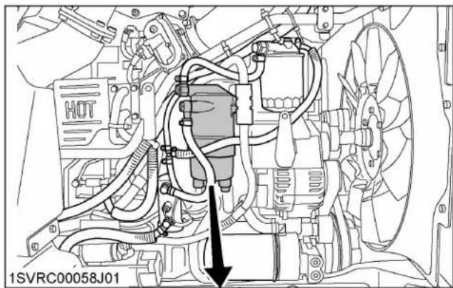
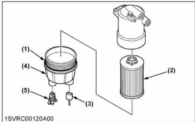
(1) O-ring
(2) Element
(3) Water sensor connector
(4) Cup
(5) Drain plug
IMPORTANT :
- If the water separator and/or fuel filter is not well maintained, the supply pump and injector may be damaged earlier than expected.
3. Cleaning fuel solenoid pump element
- Close the fuel shutoff-valve.
- Unscrew the cover's nut and remove the cover from the fuel solenoid pump.
- Remove the cover, magnet, and element and clean with kerosene.
- Refer to the following diagram and reassemble the parts as they were before.
- Open the fuel shutoff-valve.
IMPORTANT :
- When assembling the parts, be careful that no dirt or dust contacts them.
- Be sure to install the cover securely.
• After assembly, be sure to bleed the air from the fuel system.
(See Bleeding fuel system on page 277.)

natural_image
Technical diagram of an internal combustion engine assembly with valve and housing components (no text or labels)(1) Fuel solenoid pump

(1) Element
(2) Magnet
(3) Gasket
(4) Cover
(5) Nut
(6) Pin
(A) "TIGHTEN"
(B) "LOOSEN"
(C) "Tighten the cover until the end of the slot contacts the pin."
INITIAL 500 HOURS
With a new machine, be sure to do the following servicing after the first 500 operating hours.
1. Changing transmission fluid
(See Changing transmission fluid on page 269.)
2. Changing rear axle case oil
(See Changing rear axle case oil on page 271.)
3. Replacing transmission oil filter
(See Replacing transmission oil filter on page 270.)
EVERY 500 HOURS
1. Changing engine oil

WARNING
To avoid personal injury or death:
- Be sure to stop the engine before changing the oil.
-
Allow the engine to cool down sufficiently; oil can be hot and can burn.
-
To drain the used oil, remove the drain plug at the bottom of the engine and drain the oil completely into the oil pan.
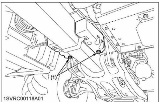
(1) Drain plug
- After draining reinstall the drain plug.
- Fill with the new oil up to the upper notch on the dipstick.
(See LUBRICANTS, FUEL AND COOLANT on page 233.)
Oil capacity with filter 22.0 L (5.8 U.S.gals.)

(1) Oil inlet
(2) Dipstick
(A) Oil level is acceptable within this range
IMPORTANT :
- Use DPF-compatible oil (CJ-4) for the engine.
2. Replacing engine oil filter

WARNING
To avoid personal injury or death:
- Be sure to stop the engine before replacing the oil filter cartridge.
-
Allow the engine to cool down sufficiently; oil can be hot and can burn.
-
Remove the oil filter.
- Put a film of clean engine oil on the rubber seal of the new filter.
- Tighten the filter quickly until it contacts the mounting surface.
Tighten the filter by hand an additional 1/2 turn only.
- After the new filter has been replaced, the engine oil normally decreases by a small amount. Make sure that the engine oil does not leak through the seal and be sure to check the oil level on the dipstick. Then replenish the engine oil up to the prescribed level.

(1) Engine oil filter
IMPORTANT :
• To prevent serious damage to the engine, use only a Kubota genuine filter.
3. Replacing hydraulic oil filter (suction)

WARNING
To avoid personal injury or death:
- Be sure to stop the engine before changing the oil filter cartridge.
-
Allow engine to cool down sufficiently, oil can be hot and can burn.
-
Place the oil pan underneath the hydraulic oil filter.
-
Remove the oil filter.
Power shift transmission type
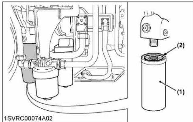
(1) Hydraulic oil filter
(2) O-ring
CVT type

(1) Hydraulic oil filter
(2) O-ring
- Put a film of clean transmission oil on the rubber seal of the new filter.
- Tighten the filter quickly until it contacts the mounting surface.
Tighten filter by hand an additional 1/2 turn only. - After the new filter has been replaced, fill the transmission oil up to the upper line of the sight glass.
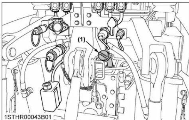
(1) Filling plug
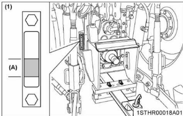
(1) Sight glass (A) Oil level is acceptable within this range
- After running the engine for a few minutes, stop the engine, wait for 10 minutes and check the oil level again, add oil to the prescribed level.
- Make sure that the transmission fluid doesn't leak past the seal on the filter.
IMPORTANT :
• To prevent serious damage to the hydraulic system, use only a Kubota genuine filter.
NOTE :
- Check the transmission fluid level under the following conditions:
a. Park the machine on a flat surface.
b. Lower the rear 3-point hitch and front end loader (if equipped).
c. Raise the front 3-point hitch (if equipped).
d. Disconnect all the remote control valve hoses.
e. Shut off engine and wait for 10 minutes.
4. Replacing hydraulic oil filter (return)

WARNING
To avoid personal injury or death:
- Be sure to stop the engine before changing the oil filter.
-
Allow engine to cool down sufficiently, oil can be hot and can burn.
-
Place the oil pan underneath the hydraulic oil filter.
- Using a wrench, remove the filter cover.
- When oil is no longer dripping from the exposed area, remove the element and replace it with a new one.
Make sure at this time that the O-ring is mounted on the element mounting part.
Power shift transmission type

(1) Hydraulic oil filter cover
(2) Nut
(3) Element
(4) O-ring
CVT type

(1) Hydraulic oil filter cover
(2) Nut
(3) Element
(4) O-ring
-
Mount after cleaning the filter cover. If the o-ring is damaged, make sure to replace it.
-
Fill the transmission oil up to the upper line of the sight glass.
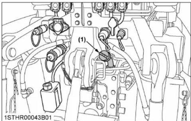
(1) Filling plug

(1) Sight glass (A) Oil level is acceptable within
this range
- After running the engine for a few minutes, stop the engine, wait for 10 minutes and check the oil level again, add oil to the prescribed level.
- Make sure that the transmission fluid doesn't leak past the seal on the filter.
NOTE :
- Check the transmission fluid level under the following conditions:
a. Park the machine on a flat surface.
b. Lower the rear 3-point hitch and front end loader (if equipped).
c. Raise the front 3-point hitch (if equipped).
d. Disconnect all the remote control valve hoses.
e. Shut off engine and wait for 10 minutes.
5. Replacing power steering oil filter

WARNING
To avoid personal injury or death:
- Be sure to stop the engine before changing the oil filter.
-
Allow engine to cool down sufficiently, oil can be hot and can burn.
-
Place the oil pan underneath the power steering oil filter.
-
Using a wrench, remove the filter cover.
-
When oil is no longer dripping from the exposed area, remove the element and replace it with a new one.
Make sure at this time that the O-ring is mounted on the element mounting part.
Power shift transmission type
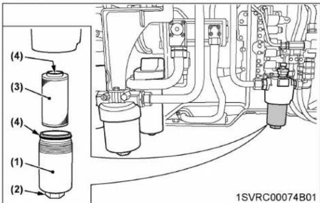
(1) Power steering oil filter cover
(2) Nut
(3) Element
(4) O-ring
CVT type
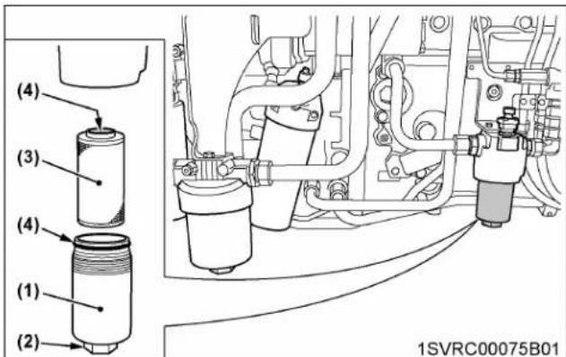
(1) Power steering oil filter cover
(2) Nut
(3) Element
(4) O-ring
-
Mount after cleaning the filter cover. If the o-ring is damaged, make sure to replace it.
-
Fill the transmission oil up to the upper line of the sight glass.
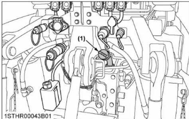
(1) Filling plug
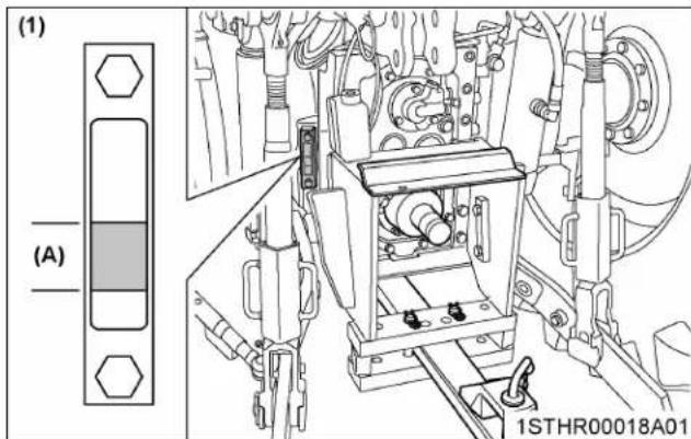
(1) Sight glass (A) Oil level is acceptable within this range
-
After running the engine for a few minutes, stop the engine, wait for 10 minutes and check the oil level again, add oil to the prescribed level.
-
Make sure that the transmission fluid does not leak past the seal on the filter.
NOTE :
- Check the transmission fluid level under the following conditions:
a. Park the machine on a flat surface.
b. Lower the rear 3-point hitch and front end loader (if equipped).
c. Raise the front 3-point hitch (if equipped).
d. Disconnect all the remote control valve hoses.
e. Stop engine and wait for 10 minutes.
6. Checking radiator hose and clamp
Check to see if the radiator hoses are properly fixed every 500 hours of operation.
-
If the hose clamps are loose or water leaks, tighten the bands securely.
-
Replace the hoses and tighten the hose clamps securely, if the radiator hoses are swollen, hardened or cracked.
Replace the hoses and hose clamps every 4 years or earlier if they are found to be swollen, hardened or cracked.

(1) Radiator hoses
(2) Hose clamps
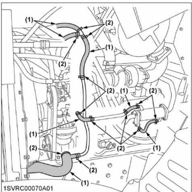
(1) Radiator hoses
(2) Hose clamps
6.1 Overheating countermeasures
Take the following actions in the event the coolant temperature is nearly at or over the boiling point, also called "overheating".
- Park the tractor in a safe place and keep the engine idling unloaded.
- Allow the engine to idle unloaded for about 5 minutes before stopping it, rather than stopping it suddenly.
- Keep away from the machine for another 10 minutes or while the steam blows out.
- Check that there are no dangers such as burns. Get rid of the causes of overheating according to the troubleshooting section of this manual. (See TROUBLESHOOTING on page 286.) Afterward, restart the engine.
7. Checking intake air line
- Check to see that hoses and hose clamps are tight and not damaged.
- If the hoses and clamps are found to be worn or damaged, replace or repair them at once.
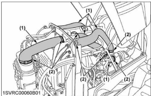
(1) Hose
(2) Hose clamps
8. Checking brake hose
Consult your local Kubota Dealer for this service.
9. Checking differential lock hose
-
Check to see that hoses and hose clamps are tight and not damaged.
-
If hoses and clamps are found worn or damaged, replace or repair them at once.
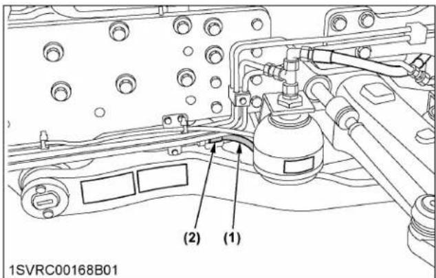
(1) Front differential lock hose
(2) Hose clamps
10. Checking lift cylinder hose
- Check to see that hoses and hose clamps are tight and not damaged.
- If hoses and clamps are found worn or damaged, replace or repair them at once.
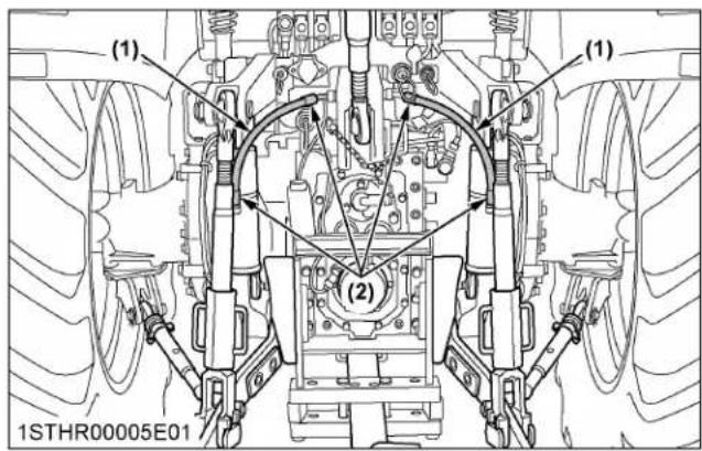
(1) Hose
(2) Hose clamps
11. Checking power steering line
- Check to see that all lines and hose clamps are tight and not damaged.
- If the hoses and clamps are found to be worn or damaged, replace or repair them at once.

(1) Power steering pressure hoses
12. Checking oil cooler line
- Check to see that all lines and hose clamps are tight and not damaged.
- If hoses and clamps are found to be worn or damaged, replace or repair them at once.

(1) Oil cooler
(2) Oil cooler line
13. Checking front suspension hose
-
Check to see that all lines and hose clamps are tight and not damaged.
-
If hoses and clamps are found to be worn or damaged, replace or repair them at once.

(1) Front suspension pressure hoses

(1) Front suspension pressure hoses
14. Checking air conditioner pipe and hose
- Check to see that all lines and hose clamps are tight and not damaged.
- If hoses and clamps are found to be worn or damaged, consult your local Kubota Dealer for this service.

(1) Air conditioner hoses
15. Checking air conditioner drive belt
WARNING
To avoid personal injury or death:
- Be sure to stop the engine before checking the belt tension.
| Proper belt tension | A deflection of between 10 to 12 mm (0.4 to 0.5 in.) when the belt is pressed (98 N / 10 kgf) in the middle of the span. |
The belt is of self-tension type and needs no readjustment. Check the belt tension in the following procedure. If the deflection is out of specification or the belt itself is found damaged, replace it with a new one.
- Stop the engine and remove the key.
- Press on the spot indicated in the following figure to measure the deflection.

(1) Air conditioner belt (A) Check the belt tension
15.1 Replacing the belt
- Apply a square wrench into the square hole of the air conditioner belt self-tension arm.
-
Using the wrench in place, unlock the self-tension arm and undo the belt from the compressor pulley.
-
In applying a new belt, also unlock the self-tension arm with the same wrench.
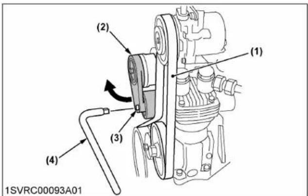
(1) Air conditioner belt
(2) Self-tension arm
(3) Square hole
(4) Square wrench
16. Changing front PTO oil (if equipped)
Cleaning oil filter
- To drain the used oil, remove the drain and filling plug at the front PTO case and drain the oil completely into the oil pan.
- After draining, reinstall the drain plug.
- Remove the internal retaining ring and loosen the M8 bolt to remove the cover.
- Extract the oil filter from the pump unit and clean it.
- Reassemble the removal parts.
- Fill with the new oil up to the lower rim of filling plug port. (See LUBRICANTS, FUEL AND COOLANT on page 233.)
- After filling reinstall the filling plug.
| Oil capacity 2.7 L | (2.9 U.S.qts.) |

(1) Drain plug
(2) Filling plug
(3) Internal retaining ring
(4) M8 bolt
(5) Pump unit
EVERY 1000 HOURS
1. Changing transmission fluid

WARNING
To avoid personal injury or death:
- Allow the engine to cool down sufficiently; oil can be hot and can burn.
- To drain the used oil, remove the drain plug at the bottom of the transmission case and drain the oil completely into the oil pan.
- After draining, reinstall the drain plug.
- Fill with new oil up to the upper line of the sight glass.
(See LUBRICANTS, FUEL AND COOLANT on page 233.)
- After running the engine for a few minutes, stop it and wait for 10 minutes.
Check the oil level again; add oil to the prescribed level.
| Oil capacity | Power shift model: 85 L (22.5 U.S.gals.)CVT model: 80 L (21.1 U.S.gals.) |

(1) Drain plug

(1) Drain plug

(1) Filling plug

(1) Sight glass (A) Oil level is acceptable within this range.
IMPORTANT :
- Do not operate the tractor immediately after changing the transmission fluid. Run the engine at medium speed for a few minutes to prevent damage to the transmission.
2. Replacing transmission oil filter
WARNING
To avoid personal injury or death:
- Be sure to stop the engine before changing the oil filter.
-
Allow engine to cool down sufficiently, oil can be hot and can burn.
-
Place the oil pan underneath the transmission oil filter.
-
Using a wrench, remove the filter cover.
-
When oil is no longer dripping from the exposed area, remove the element and replace it with a new one.
Make sure at this time that the o-ring is mounted on the element mounting part.
Power shift transmission type

(1) Transmission oil filter cover
(2) Nut
(3) Element
(4) O-ring
CVT type

(1) Transmission oil filter cover
(2) Nut
(3) Element
(4) O-ring
- Mount after cleaning the filter cover. If the o-ring is damaged, make sure to replace it.
- Fill the transmission oil up to the upper line of the sight glass.
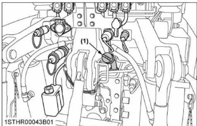
(1) Filling plug
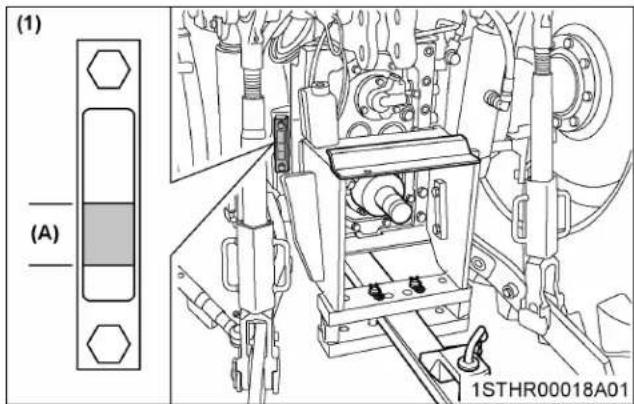
(1) Sight glass (A) Oil level is acceptable within this range
- After running the engine for a few minutes, stop the engine, wait for 10 minutes and check the oil level again; add oil to the prescribed level.
- Make sure that the transmission fluid does not leak past the seal on the filter.
NOTE :
- Check the transmission fluid level under the following conditions:
a. Park the machine on a flat surface.
b. Lower the rear 3-point hitch and front end loader (if equipped).
c. Raise the front 3-point hitch (if equipped).
d. Disconnect the all remote control valve hoses.
e. Stop engine and wait for 10 minutes.
3. Changing rear axle case oil

WARNING
To avoid personal injury or death:
- Allow engine to cool down sufficiently, oil can be hot and can burn.
- To drain the used oil, remove the drain plug and filling plug at the rear axle case and drain the oil completely into the oil pan.
- After draining, reinstall the drain plug.
- Fill with the new oil up to the lower rim of filling plug port. (See LUBRICANTS, FUEL AND COOLANT on page 233.)
- After filling, reinstall the filling plug.
Oil capacity 10 L (10.6 U.S.qts.) for each side
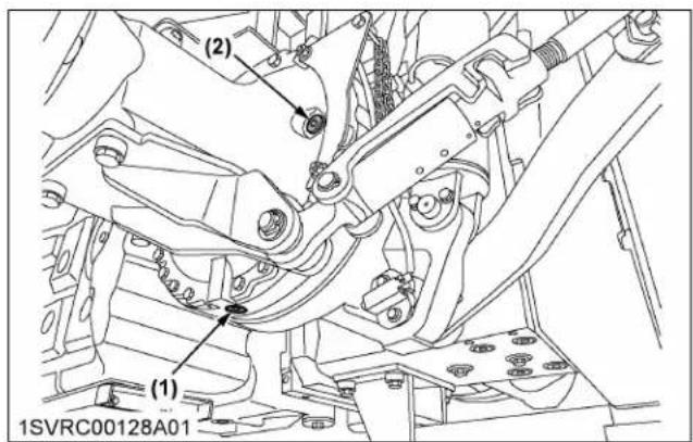
(1) Drain plug
(2) Filling plug
4. Changing front differential case oil
- To drain the used oil, remove the drain and filling plug at the front differential case and drain the oil completely into the oil pan.
- After draining, reinstall the drain plug.
- Fill with new oil up to the lower rim of filling plug port. (See LUBRICANTS, FUEL AND COOLANT on page 233.)
- After filling, reinstall the filling plug.
Oil capacity 8.5 L (9.0 U.S.qts.)
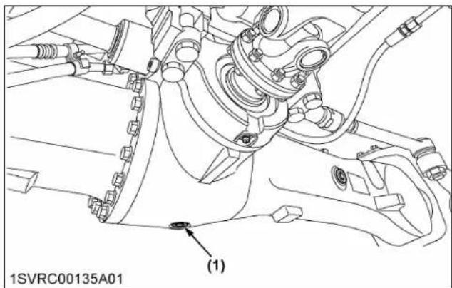
(1) Drain plug

(1) Filling plug
5. Changing front axle gear case oil
- Stop the tractor so that the gear case plug is at the bottom.
- Remove the plug and drain the oil completely into the oil pan.
- After draining the oil, rotate the gear case so that plug is aligned horizontally with the center of the gear case.
-
Fill with new oil up to the lower rim of the port. (See LUBRICANTS, FUEL AND COOLANT on page 233.)
-
After filling, reinstall the plug.
| Oil capacity | 2.1 L (2.2 U.S.qts.) for each side |
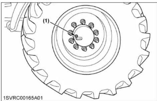
(1) Plug
6. Adjusting engine valve clearance
Consult your local KUBOTA Dealer for this service.
EVERY 1000 HOURS OR 1 YEAR
Be sure to do the following servicing once every 1000 hours or yearly, whichever comes first.
1. Replacing air cleaner primary element and secondary element
(See Cleaning air cleaner primary element on page 250.)
2. Checking exhaust manifold
Consult your local KUBOTA Dealer for this service.
EVERY 1500 HOURS
1. Cleaning fuel injector nozzle tip
Consult your local KUBOTA Dealer for this service.
2. Checking DEF/AdBlue® injector tip
Consult your local Kubota Dealer for this service.
3. Checking DEF/AdBlue® line
-
Check to see that all lines from the DEF/AdBlue injector to the tank are securely connected and not damaged.
-
If hoses and clamps are found worn or damaged, replace or repair them at once.
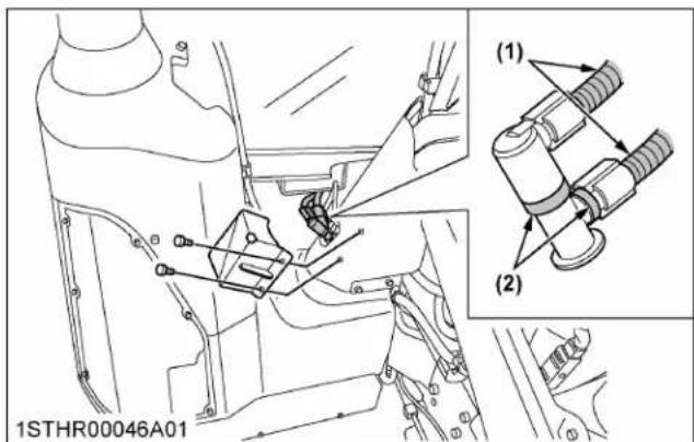
(1) DEF/AdBlue ® lines
(2) Clamp bands
4. Replacing oil separator element

WARNING
To avoid personal injury or death:
- Be sure to stop the engine before replacing the oil separator element.
- Remove the cover and take out the element. Wipe off the oil and the carbon from inside the case with a clean rag.
- Fit in a new oil separator element.
- Tighten the cover.

(1) Body
(2) Oil separator element
(3) Gasket
(4) Cover
5. Checking positive crankcase ventilation (PCV) valve
Consult your local KUBOTA Dealer for this service.
6. Checking and cleaning EGR cooler
Consult your local KUBOTA Dealer for this service.
7. Checking accumulator (front suspension type)
Consult your local KUBOTA Dealer for this service.
EVERY 2000 HOURS OR 2 YEARS
Be sure to do the following servicing once every 2000 hours or biennially, whichever comes first.
1. Flushing cooling system and changing coolant

WARNING
To avoid personal injury or death:
- Do not remove the radiator cap while the coolant is hot. When cool, slowly rotate the cap to the first stop and allow sufficient time for excess pressure to escape before removing the cap completely.
- Stop the engine and let it cool down.
- Connect the extension drain hose to the drain plug.
- To drain the coolant, loosen the drain plug and remove the radiator cap. The radiator cap must be removed to completely drain the coolant.
- After all coolant is drained, tighten the drain plug securely.
- Fill with clean soft water and cooling system cleaner.
- Follow directions of the cleaner instruction.
- After flushing, fill with clean soft water and antifreeze up to the upper line of recovery tank.
- Install the radiator cap securely.
- Start and operate the engine for a few minutes.
- Stop the engine. Check coolant level and add coolant if necessary.
- Properly dispose of used coolant.
Coolant capacity 24 L (6.3 U.S.gals.)

(1) Drain plug
(2) Extension drain hose

(1) Recovery tank
(2) Radiator cap
(A) [MAX]
(B) [MIN]
IMPORTANT :
- Do not start engine without coolant.
- Use clean, fresh soft water and antifreeze to fill the radiator and recovery tank.
- When mixing the antifreeze with water, the antifreeze mixing ratio is 50%.
- Securely tighten radiator cap. If the cap is loose or improperly fitted, water may leak out and the engine could overheat.
NOTE :
- On CAB type machines, coolant circulates through the heater. This means that one more liter or so of coolant is required.
In changing coolant, pour coolant up to the filler port of the recovery tank. Turn on the heater (shift the temperature control dial toward "WARM"), and run the engine for a while in order to warm coolant. Then stop the engine.
When coolant has cooled down, some of the coolant in the recovery tank is sucked. Now the recovery tank is appropriately filled with coolant.
2. Antifreeze

WARNING
To avoid personal injury or death:
- When using antifreeze, put on some protection such as rubber gloves (antifreeze contains poison).
- If you swallow the antifreeze, seek immediate medical help. Do not make a person throw up unless told to do so by a poison control or a healthcare professional. Use standard first aid and CPR for signs of shock or cardiac arrest. Call your local poison control center or your local emergency number for further assistance.
- When antifreeze comes in contact with the skin or clothing, wash it off immediately.
- Do not mix different types of antifreeze. The mixture can produce chemical reactions resulting in harmful substances.
- Antifreeze is extremely flammable and explosive under certain conditions. Keep fire and children away from antifreeze.
- When draining fluids from the engine, place a container underneath the engine body.
- Do not pour waste onto the ground, down a drain, or into any water source.
- Also, observe the relevant environmental protection regulations when disposing of antifreeze.
Always use a 50/50 mix of long-life coolant and clean soft water in KUBOTA engines.
Consult your local KUBOTA Dealer concerning coolant for extreme conditions.
- Long-life coolant (hereafter LLC) comes in several types. Use ethylene glycol (EG) type for this engine.
- Before employing LLC-mixed cooling water, fill the radiator with fresh water and empty it again. Repeat this procedure 2 or 3 times to clean up the inside.
- Mixing the LLC Premix 50% LLC with 50% clean soft water. When mixing, stir it up well, and then pour it into the radiator.
- The procedure for the mixing of water and antifreeze differs according to the make of the antifreeze and the ambient temperature. Refer to SAE J1034 standard, more specifically also to SAE J814c.
| Vol % antifreeze | Freezing point | Boiling point*1 | ||
| °C | °F | °C | °F | |
| 50 | -37 | -34 | 108 | 226 |
*1 At 1.013 × 10⁵ Pa (760 mmHg) pressure (atmospheric). A higher boiling point is obtained by using a radiator pressure cap which permits the development of pressure within the cooling system.
5. Adding the LLC
a. Add only water if the mixture level is reduced by evaporation.
b. If there is a mixture leak, add LLC of the same manufacturer and type in the same mixture percentage.
IMPORTANT :
- Never add any long-life coolant from a different manufacturer. Different brands may have different additive components, and the engine may fail to perform as specified.
-
When the LLC is mixed, do not employ any radiator cleaning agent. The LLC contains anticorrosive agent. If mixed with the cleaning agent, sludge may build up, adversely affecting the engine parts.
-
KUBOTA's genuine long-life coolant has a service life of 2 years. Be sure to change the coolant every 2000 hours or every 2 years, whichever comes first.
NOTE :
- The above data represents industry standards that necessitate a minimum glycol content in the concentrated antifreeze.
EVERY 3000 HOURS
1. Checking turbocharger
Consult your local KUBOTA Dealer for this service.
2. Checking supply pump
Consult your local KUBOTA Dealer for this service.
3. Checking and cleaning EGR system
Consult your local KUBOTA Dealer for this service.
4. Checking DEF/AdBlue ® injector
Consult your local KUBOTA Dealer for this service.
5. Replacing DEF/AdBlue® pump filter
- Clean around the filter cover.
- Loosen the filter cover and detach the cover and the element together.
- Draw the element out of the cover and replace the element with a new one.
NOTE :
- Even after stopping the engine, the injector cooling DEF/AdBlue® fluid continues to circulate through the circuit for a couple of minutes.
When this circulation has ended, do the replacement job. During cooling, the fluid's circulating noise is heard.
- Do not apply oil to the o-ring of the cover.

(1) Filter cover
(2) Element
(3) O-ring
EVERY 4000 HOURS
1. Cleaning DPF muffler
1. Remove the ash.
The longer the DPF operates, the more ash (burnt residue) is collected in the filter. Too much ash build-up adversely affects the DPF performance. Consult your local KUBOTA Dealer to clean the filter.
IMPORTANT :
- The DPF needs to be cleaned with a specific cleaning device. Do not disassemble the DPF for cleaning or attempt to clean it yourself. Consult your local KUBOTA Dealer.
EVERY 1 YEAR
1. Checking DPF differential pressure sensor pipe
Consult your local KUBOTA Dealer for this service.
2. Checking EGR pipe
Consult your local KUBOTA Dealer for this service.
3. Checking oil separator hose
Consult your local Kubota Dealer for this service
4. Checking antifrost heater for oil separator (if equipped)
Consult your local KUBOTA Dealer for this service.
5. Checking CAB isolation cushion
Check the cushion for any breakage or fatigue. Replace them if they have deteriorated.
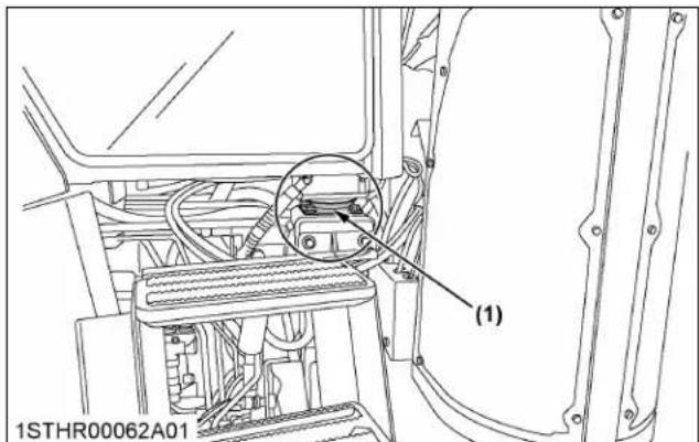
(1) CAB isolation cushion
EVERY 2 YEARS
1. Replacing DPF differential pressure sensor hose
Consult your local KUBOTA Dealer for this service.
2. Replacing boost sensor hose
Consult your local KUBOTA Dealer for this service.
3. Replacing fuel hose
Consult your local Kubota Dealer for this service.
EVERY 3 YEARS
1. Replacing parking brake cable
Consult your local KUBOTA Dealer for this service.
EVERY 4 YEARS
1. Replacing radiator hose (water pipes)
Replace the hoses and clamps.
(See Checking radiator hose and clamp on page 265.)
2. Replacing intake air line
Consult your local KUBOTA Dealer for this service.
3. Replacing oil separator hose
Consult your local Kubota Dealer for this service.
4. Replacing oil cooler line
Consult your local KUBOTA Dealer for this service.
5. Replacing power steering line
Consult your local KUBOTA Dealer for this service.
6. Replacing lift cylinder hose
Consult your local KUBOTA Dealer for this service.
7. Replacing suspension hose (front suspension type)
Consult your local KUBOTA Dealer for this service.
8. Replacing differential lock hose
Consult your local KUBOTA Dealer for this service.
9. Replacing brake hose
Consult your local KUBOTA Dealer for this service.
10. Replacing air conditioner hose
Consult your local KUBOTA Dealer for this service.
SERVICE AS REQUIRED
1. Bleeding fuel system
Air must be removed:
- When the fuel filter or lines are removed.
- When water is drained from water separator.
- When tank is completely empty.
• After the tractor has not been used for a long period of time.
Bleeding procedure is as follows:
- Fill the fuel tank with fuel, and open the fuel shutoff valve.
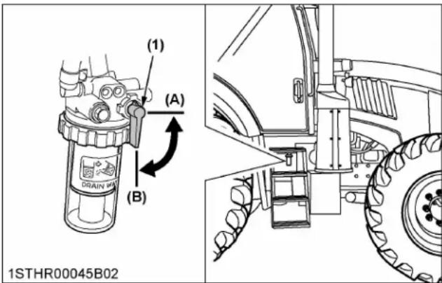
(1) Fuel shutoff valve (A) "CLOSE"
(B) "OPEN"
- Turn on and off the key switch repeatedly 10 times or so at the following intervals. This lets the air out of the fuel line.
a. Key switch "ON" time: 30 seconds
b. Key switch "OFF" time: 15 seconds

flowchart
graph TD
    A["STOP"] --> B["Current Source"]
    B --> C["Current Source"]
    C --> D["Directional Arrow (A)"]
    D --> E["Directional Arrow (B)"]
    style A fill:#f9f,stroke:#333
    style B fill:#ccf,stroke:#333
    style C fill:#cfc,stroke:#333
    style D fill:#fcc,stroke:#333
    style E fill:#ffc,stroke:#333
(1) Key switch (A) "ON"
(B) "OFF"
- Set both the hand and the foot throttles to the minimum speed position, turn the key switch to start the engine and then reset the throttle at the mid speed (around 1500 rpm) position.
If engine doesn't start, try it several times at 30 second intervals.
IMPORTANT :
- Do not hold key switch at engine start position for more than 10 seconds continuously. If more engine cranking is needed, try again after 30 seconds.
- Accelerate the engine to remove the small portion of air left in the fuel system.
- If air still remains and the engine stops, repeat the previous steps.
2. Bleeding brake system
Consult your local KUBOTA Dealer for this service.
3. Replacing fuses
The tractor electrical system is protected from potential damage by fuses.
A blown fuse indicates that there is an overload or short somewhere in the electrical system.
If any of the fuses should blow, replace with a new one of the same capacity.
IMPORTANT :
- Before replacing a blown fuse, determine why the fuse blew and make any necessary repairs. Failure to follow this procedure may result in serious damage to the tractor electrical system. For specific information dealing with electrical problems, read the troubleshooting section of this manual or contact your local Kubota Dealer. (See TROUBLESHOOTING on page 286.)

(1) Fuses

| Fuse No. | Capacity (A) | Protected circuit |
| F1 10 | Brake light trailer | |
| F2 7.5 | Marker lights right | |
| F3 7.5 | Marker lights left |
(Continued)
| Fuse No. | Capacity (A) | Protected circuit |
| F4 5 | Auto steering | |
| F5 10 | Diagnostic connector | |
| F6 25 | ISOBUS ecu power | |
| F7 15 | High beam | |
| F8 15 | Low beam | |
| F9 7.5 | TCU | |
| F10 7.5 | VDC | |
| F11 2 | Alternator | |
| F12 5 | 3P socket | |
| F13 5 | Front loader | |
| F14 5 | Light switch | |
| F15 5 | A/C-system | |
| F16 10 | Wiper front and defogger | |
| F17 30 | Worklight roof front | |
| F18 10 | Mirror heating | |
| F19 15 | Seat | |
| F20 15 | Main fuse | |
| F21 5 | Ignition | |
| F22 15 | Brake light | |
| F23 10 | Signal socket | |
| F24 10 | A/C-compressor | |
| F25 7.5 | Auto steering iBox | |
| F26 15 | Worklight C-pillar | |
| F27 30 | Main fuse | |
| F28 15 | Worklight A-pillar | |
| F29 10 | Dashboard | |
| F30 15 | Back lamp | |
| F31 2 | Terminal | |
| F32 5 | VCU2 | |
| F33 5 | Switch panel | |
| F34 5 | Armrest unit | |
| F35 | ||
| F36 5 | ECU | |
| F37 7.5 | TCU | |
| F38 7.5 | Autosteer valve | |
| F39 15 | Worklight roof rear | |
| F40 10 | VCU1 | |
| F41 15 | Beacon light | |
| F42 15 | Wiper rear/CAB-light | |
| F43 5 | GPS antenna | |
| F44 5 | Battery main relais | |
| F45 5 | Dashboard | |
| F46 5 | Radio |
(Continued)
(Continued)
| Fuse No. | Capacity (A) | Protected circuit |
| F47 | ||
| F48 5 | Armrest unit | |
| F49 5 | VCU1 | |
| F50 5 | Battery main switch OFF | |
| F51 5 | VCU2 | |
| F52 30 | Worklight bonnet | |
| F53 7.5 | TCU | |
| F54 | ||
| F55 7.5 | VDC | |
| F56 40 | A/C blower | |
| F57 7.5 | Horn | |
| F58 15 | Trailer brake pneumatic | |
| F59 7.5 | Terminal | |
| F60 15 | Flasher relay | |
| F61 20 | Air dryer | |
| F62 30 | Defogger | |
| F63 10 | Ignition switch | |
| F64 | ||
| F65 15 | Cigarette lighter | |
| F66 15 | Front loader | |
| F67 15 | Trailer socket rear | |
| F68 15 | Trailer socket front | |
| F69 15 | Trailer brake pneumatic | |
| F70 | ||
| F71 25 | 3P-socket | |
| F72 70 | Main fuse | |
| F73 30 | VCU2 | |
| F74 70 | Main fuse ignition | |
| F75 60 | ISOBUS actuator power | |
| F76 25 | 3P-socket No. 2 | |
| F77 5 | TECU |
Protected circuit

| Fuse No. Capacity (A) Protected circuit | |
| 1 30 A Spare | |
| 2 30 A ACU | |
| 3 60 A Glow | |
| 4 5 A Sedimenter | |
| 5 20 A ACU comp | |
| 6 30 A ECU | |
| 7 10 A NOX | |
| 8 15 A 30 Permanent | |
| 9 5 A EGR | |
Protected circuit

| Fuse No. Capacity (A) Protected circuit | |
| 1 150 A Electrical CAB | |
| 2 80 A Power train | |
Protected circuit

| Fuse No. | Capacity (A) Protected circuit | |
| 1 | 175 A(with 150 A alternator) | Alternator |
| 225 A(with 200 A alternator) | ||
4. Replacing light bulb
| Light Capacity | |
| Headlight 60/55 W | |
| Repeat headlight 60/55 W | |
| Turn signal and hazard light (front) 21 W | |
| Turn signal and hazard light (rear fender) LED | |
| Turn signal and hazard light (CAB rear piller) 21 W | |
| Front position light 10 W | |
| Brake stop light LED | |
| Tail light LED | |
| Front work light (hood) 55 W | |
| Front work light (CAB outer roof) 55 W | |
| Front work light (CAB front piller) 24 W | |
| Rear work light (CAB outer roof) 55 W | |
| Rear work light (CAB rear piller) 24 W | |
| Dome light (room lamp) | 5 W |
| Instrument panel light | 3 W |
5. Replacing head lamp

CAUTION
To avoid personal injury:
- Be careful not to drop the bulb, hit anything against the lamp, apply excess force, or get the lamp scratched. If broken, the glass may cause injury. Pay more attention to halogen lamps in particular, which have high pressure inside.
- Before replacing the lamp, be sure to turn off the light and wait until the bulb cools down; otherwise, you may get burned.
IMPORTANT :
- Be sure to use a new bulb of the specified wattage.
- Never touch the bulb surface (glass) with bare hands. Fingerprints, for example, may break the bulb.
6. Lubricating points for door and window

(1) Door hinge
(2) Rear window hinge
7. Adding washer liquid
Add a proper amount of automobile washer liquid.
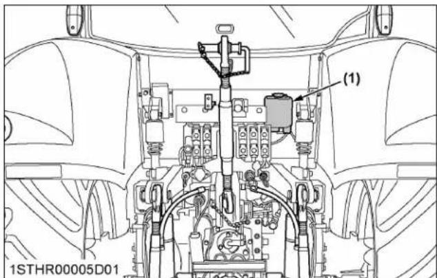
(1) Washer liquid tank
| Washer tank capacity | 2.0 L (2.1 U.S.qts.) |
8. Checking amount of refrigerant (gas)

WARNING
To avoid personal injury or death:
- Liquid contact with eyes or skin may cause frostbite.
- In the event of a leakage, wear safety goggles. Escaping refrigerant can cause severe injuries to eyes.
• In contact with a flame, R134a refrigerant produces a toxic gas. - Do not disconnect any part of the refrigeration circuit of the air conditioning system. Consult your local KUBOTA Dealer for assistance and service.
A shortage of refrigerant impairs the air conditioner performance. Check the following points. If it is indicated that the amount of refrigerant is extremely low, ask your dealer to inspect and refill.
Checking procedure
- Run the air conditioner in the following conditions.
• Engine speed - About 1500 rpm
• Temperature control dial - Maximum cooling position
• Fan switch - Highest blow
• Air conditioner switch - "ON"
- Look into the sight glass to see if and how the refrigerant is flowing through its circuit.

(1) Sight glass

Proper
Little or no air bubbles in the refrigerant flow.

Low
Lots of air bubbles in the refrigerant flow (air bubbles or foam passing continuously).

Overfull or no re-
frigerant:
Colorless and transparent.
IMPORTANT :
- Charge only with R134a not R12 refrigerant.
9. Washing the tractor
Misuse of the high pressure washer may cause personal injury or machine damage, as well as the failure or malfunction of the machine. Follow the instruction manual and the labels on the high pressure washer, and use it properly.

CAUTION
To avoid personal injury:
• To prevent the machine from being damaged, set the washing nozzle to spreading water, and keep the distance 2 m away from the machine to clean it. When the water is directed at a pin point area, or when the machine is washed from too close a position with a high pressure flow:
- The cover of the wirings may be damaged or the wiring may be cut off, causing fire.
- The hydraulic hose may be damaged, causing a high pressure oil blow out. This may cause injury.
IMPORTANT :
- If the machine is not washed as specified, the following peel-off, damage or malfunction may result.
Examples:
– The stickers or labels may peel away.
- The electronic components, engine compartment, transmission case, CAB and others may get wet inside and adversely affected.
- The crawlers, tires, oil seals and other rubber-based components, the decorative covers and other plastic-based components, and the windows and other glass-based components may get damaged.
- The paints, coatings and platings may peel away.
No high pressure-washer

(A) High pressure
(B) Low pressure
No pressure-washer at short range
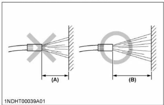
(A) Less than 2 m
(B) More than 2 m
IMPORTANT :
- Do not apply high pressure water to the glass part of the CAB or the roof part while washing. Please lower the pressure or spread the water flow. It will cause water leakage inside the CAB and cause damage to electrical parts.
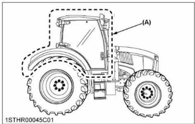
(1) No high pressure-washer
STORAGE

WARNING
To avoid personal injury or death:
- Do not clean the machine while the engine is running.
- To avoid the danger of exhaust fume poisoning, do not operate the engine indoors without proper ventilation.
- When storing the tractor, remove the key from the key switch to prevent unauthorized persons from operating the tractor and getting injured.
TRACTOR STORAGE
If you intend to store your tractor for an extended period of time, follow the procedures outlined below.
These procedures will ensure that the tractor is ready to operate with minimum preparation when it is removed from storage.
- Check the bolts and nuts for looseness and tighten if necessary.
- Apply grease to tractor areas where bare metal will rust, and also to pivot areas.
- Detach the weights from the tractor body.
- Inflate the tires to a pressure a little higher than usual.
- Change the engine oil and run the engine to circulate oil throughout the engine block and internal moving parts for about 5 minutes.
- With all implements lowered to the ground, coat any exposed hydraulic cylinder piston rods with grease.
- Park tractors equipped with the front suspension system with the suspension cylinders in the lowest position using manual control mode.
- Remove the battery from the tractor. Store the battery following the battery storage procedures. (See Checking battery condition on page 253.)
- Preferably, drain the DEF/AdBlue ® out of its tank and store the fluid in another specific tank. Details regarding the long-term storage of DEF/AdBlue ® can be found in a different section. (See Storing and handling DEF/AdBlue ® on page 121.)
- Keep the tractor in a dry place where the tractor is sheltered from the elements. Cover the tractor.
- Store the tractor indoors in a dry area that is protected from sunlight and excessive heat. If the tractor must be stored outdoors, cover it with a waterproof tarpaulin.
Jack the tractor up and place blocks under the front and rear axles so that all 4 tires are off the ground. Keep the tires out of direct sunlight and extreme heat.
IMPORTANT :
- When washing the tractor, be sure to stop the engine. Allow sufficient time for the engine to cool down before washing.
- Before removing the battery cable, make sure that the battery switch indicator is off. Do not remove the cable while the indicator is lit or blinking. For handling of the battery switch, refer to Setting the battery switch on page 121.
- Cover the tractor after the muffler and the engine have cooled down.
REMOVING THE TRACTOR FROM STORAGE
- Check the tire air pressure and inflate the tires if needed.
- Jack the tractor up and remove the support blocks from under the front and rear axles.
- Install the battery. Before installing the battery, be sure it is fully charged.
- Check the fan belt tension.
- Check all fluid levels (engine oil, transmission and hydraulic oil, engine coolant, DEF/AdBlue ® and any attached implements).
- Start the engine. Observe all gauges. If all the gauges are functioning properly and have normal readings, move the tractor outside. Once outside, park the tractor and let the engine idle for at least 5 minutes. Shut the engine off and walk around tractor and make a visual inspection looking for evidence of oil or water leaks.
- With the engine fully warmed up, release the parking brake and test the brakes for proper adjustment as you move forward. Adjust the brakes as necessary.
TROUBLESHOOTING
ELECTRIC CONTROLLER TROUBLE SHOOTING
If any of the electric control system has trouble or miss-operation happens, an error or warning code appears on the LCD of the instrument panel. An error/warning message appears on the K-monitor as well (if equipped).
In some case, the buzzer starts sounding or the master caution LCD indicator lights up.
If the error/warning code appears, please take the necessary action according to the following table.
An error/warning code on the LCD can be made to disappear from the LCD by pressing the [ESC] button. If another trouble happens, the error/warning code re-appears with another trouble code. When this happens, this error/warning code and the immediately previous error are both indicated at 2-seconds intervals.
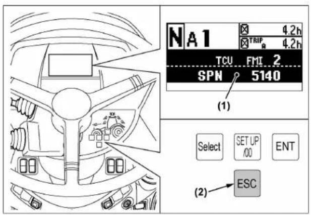
1STHR00072A01

(3)
(1) Warning or error code on LCD
(2) ESC button
(3) Warning or error message on K-monitor
Error and Warning code display on LCD

1STHR00073A01
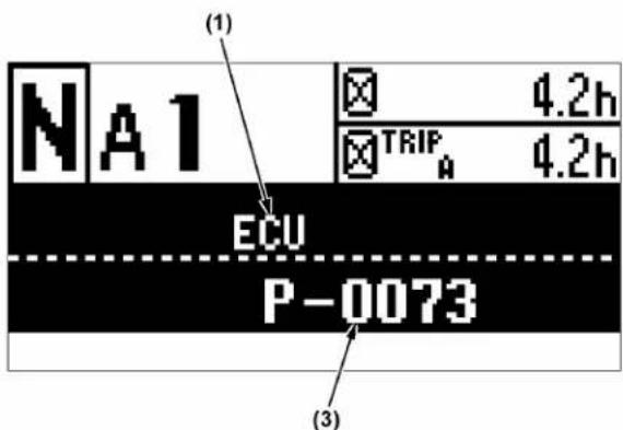
(1) Name of electric control unit
(2) Error or warning code for except engine
(3) Error or warning code for engine
The abbreviated electric control unit name shows which control unit is in trouble.
The error/warning code is identified with a combination of FMI and SPN or P or U code.
The meaning of each electric control unit name is listed in the following table.
| Abbreviation name Name of electric control unit | |
| ECU Engine control unit | |
| ACU After treatment control unit | |
| TCU Transmission control unit | |
| VDC Vehicle drive control unit | |
| VCU1 Vehicle control unit 1 | |
| VCU2 Vehicle control unit 2 | |
| ARU Arm rest unit | |
| CEU Central electric control unit | |
| TECU Tractor ECU (ISO-BUS) | |
| SWP Switch panel | |
| NAC Navigation control | |
| SC Steering control | |
Table of error/warning code
If an error/warning code which is not indicated in the following table is indicated, please contact your authorized local KUBOTA Dealer.
| Electric control unit | Error or warning code | Type of trouble Action | ||
| SPN FMI | ||||
| ECU | P0217 | Engine overheat. | Reduce work load.Check cooling system; as coolant, radiator net, fan belt tension. | |
| 110 0 | ||||
| ACU | P204F | DEF/AdBlue®level is too low. | Check DEF/AdBlue®level.Check tank for leakage. | |
| 1761 1 | ||||
| ACU | P20F5 | DEF/AdBlue®level is too low. | Check DEF/AdBlue®level.Check tank for leakage. | |
| 4350 15 | ||||
| ACU | P208B | DEF/AdBlue®freeze warning. | Please stop the engine once and restart it after 10 seconds. If the error code remains, please contact your dealer. | |
| 5435 12 | ||||
| VCU1 520350 | 19 | Communication error of DBM. | Check the fuse and wiring of the dashboard. If there is no damage, contact your dealer. | |
| VCU1 520351 | 19 | Communication error of VCU2. | Check the fuse and wiring of VCU2.If there is no damage, contact your dealer. | |
| VCU1 520352 | 19 | Communication error of ECU. | Check the fuse and wiring of ECU.If there is no damage, contact your dealer. | |
| VCU1 | 520353 | 19 | Communication error of SWP. | Check the fuse and wiring of switch panel.If there is no damage, contact your dealer. |
| VCU1 520354 | 19 | Communication error of TCU. | Check the fuse and wiring of TCU.If there is no damage, contact your dealer. | |
| VCU1 520355 | 19 | Communication error of VDC. | Check the fuse and wiring of VDC.If there is no damage, contact your dealer. | |
| VCU1 520358 | 19 | Communication error of ACU. | Check the fuse and wiring of ACU.If there is no damage, contact your dealer. | |
| ARU 168 | 0 | Battery voltage is too high. | Check the battery specification.Check charging system. | |
| ARU | 168 | 1 | Battery voltage is too low. | Charge or replace. |
(Continued)
| Electric control unit | Error or warning code | Type of trouble Action | ||
| SPN FMI | ||||
| ARU 581 23 | Ratio lock button | malfunction. | Ratio lock button may be stuck.If it is stuck, contact your dealer. | |
| ARU 604 23 | Shuttle neutral button malfunc-tion. | Shuttle neutral button may be stuck.If it is stuck, contact your dealer. | ||
| ARU 522001 | 23 | Remote control valve lock button malfunction. | Remote control valve lock button may be stuck.If it is stuck, contact your dealer. | |
| ARU 522003 | 23 | 3-point hitch lock button malfunc-tion. | 3-point hitch lock button may be stuck.If it is stuck, contact your dealer. | |
| ARU 522004 | 23 | Engine rpm memory button A malfunction. | Engine rpm memory button A may be stuck.If it is stuck, contact your dealer. | |
| ARU 522005 | 23 | Engine rpm memory button B malfunction. | Engine rpm memory button B may be stuck.If it is stuck, contact your dealer. | |
| ARU 522007 | 23 | Headland management system field in button malfunction. | Headland management system field “IN” button may be stuck. If it is stuck, contact your dealer. | |
| ARU 522008 | 23 | Headland management system field out button malfunction. | Headland management system field “OUT” button may be stuck. If it is stuck, contact your dealer. | |
| ARU 522010 | 23 Cruise control | button malfunction. | Cruise control button may be stuck.If it is stuck, contact your dealer. | |
| ARU 522011 | 23 | 3-point quick raise button malfunction. | 3-point quick raise button may be stuck.If it is stuck, contact your dealer. | |
| ARU 522012 | 23 | 3-point quick lower button malfunction. | 3-point quick lower button may be stuck.If it is stuck, contact your dealer. | |
| ARU 522013 | 23 | Shuttle forward button malfunc-tion. | Shuttle forward button may be stuck.If it is stuck, contact your dealer. | |
| ARU 522014 | 23 | Shuttle reverse button malfunc-tion. | Shuttle reverse button may be stuck.If it is stuck, contact your dealer. | |
| ARU 522015 | 23 [ESC] button | malfunction. | [ESC] button may be stuck.If it is stuck, contact your dealer. | |
| ARU 522016 | 23 [HOME] button | malfunction. | [HOME] button may be stuck.If it is stuck, contact your dealer. | |
| ARU 522027 | 23 | Selection button for remote con-trol valve and loader malfunction. | Selection button for remote control valve and loader may be stuck.If it is stuck, contact your dealer. | |
| ARU 522028 | 23 Joystick lock | button malfunction. | Joystick lock button may be stuck.If it is stuck, contact your dealer. | |
| ARU 522029 | 23 Mode shift button | function. | Mode shift button may be stuck.If it is stuck, contact your dealer. | |
| ARU 522030 | 23 | Shuttle enable button malfunc-tion. | Check shuttle enable button.If it is stuck, contact your dealer. | |
| ARU 522034 | 23 4WD button | malfunction. | Check the 4WD button.If it is stuck, contact your dealer. | |
| ARU 522035 | 23 | Differential lock button malfunc-tion. | Differential lock button may be stuck.If it is stuck, contact your dealer. | |
| ARU 522042 | 23 | Loader 3rd/4th function button malfunction. | Loader 3rd/4th function button may be stuck.If it is stuck, contact your dealer. | |
| ARU 522117 | 23 [F1] function | button malfunction. | [F1] function button may be stuck.If it is stuck, contact your dealer. | |
| ARU 522217 | 23 [F2] function | button malfunction. | [F2] function button may be stuck.If it is stuck, contact your dealer. | |
(Continued)
| Electric control unit | Error or warning code | Type of trouble Action | ||
| SPN FMI | ||||
| ARU 52231 | 7 23 [F3] function | button malfunction. | [F3] function button may be stuck.If it is stuck, contact your dealer. | |
| ARU 52241 | 7 23 [F4] function | button malfunction. | [F4] function button may be stuck.If it is stuck, contact your dealer. | |
| ARU 52303 | 7 23 | Engine rpm memory adjustment button up malfunction. | Engine rpm memory adjustment button up may be stuck. If it is stuck, contact your dealer. | |
| ARU 52303 | 8 23 | Engine rpm memory adjustment button down malfunction. | Check the engine rpm memory adjustment button down. If it is stuck, contact your dealer. | |
| VCU2 566 9 | Signal error; differential lock switch. | Check if the differential lock switch is stuck open.If the message persists after the switch is closed, contact your dealer. | ||
| VCU2 696 19 | Communication error of engine speed. | The foot throttle pedal was depressed when engine was started. Release the foot throttle pedal when starting the engine. | ||
| VCU2 1873 | 2, 3 or 4 Rear lift arm sensor error. | Rear lift arm sensor or wiring may be defective; contact your dealer | ||
| VCU2 2612 | 9 Signal error; 4WD switch. | Check if the 4WD switch is stuck open.If the message persists after the switch is closed, contact your dealer. | ||
| VCU2 11014 | 9 | Signal error; external switch for 3-point hitch lifting. | Check if the external switch for 3-point hitch lifting is stuck. If not, contact your dealer. | |
| VCU2 11015 | 9 | Signal error; external switch for 3-point hitch lowering. | Check if the external switch for 3-point hitch lowering is stuck. If not, contact your dealer. | |
| VCU2 11031 | 0 or 1 Right side of draft sensor error. | Restart the engine and check message.If the message persists, contact your dealer. | ||
| VCU2 11031 | 3 or 4 Right side of draft sensor error. | Restart the engine and check message.If the message persists, contact your dealer. | ||
| VCU2 11032 | 0 or 1 Left side of draft sensor error. | Restart the engine and check message.If the message persists, contact your dealer. | ||
| VCU2 11032 | 3 or 4 Left side of draft sensor error. | Restart the engine and check message.If the message persists contact your dealer. | ||
| VCU2 | 521004 19 | Communication error of remote valve 1. | Remote valve 1 wiring may be defective; contact your dealer. | |
| VCU2 | 521005 19 | Communication error of remote valve 2. | Remote valve 2 wiring may be defective; contact your dealer. | |
| VCU2 | 521006 19 | Communication error of remote valve 3. | Remote valve 3 wiring may be defective; contact your dealer. | |
| VCU2 | 521007 19 | Communication error of remote valve 4. | Remote valve 4 wiring may be defective; contact your dealer. | |
| VCU2 | 521008 19 | Communication error of remote valve 5. | Remote valve 5 wiring may be defective; contact your dealer. | |
| VCU2 | 521009 19 | Communication error of remote valve 6. | Remote valve 6 wiring may be defective; contact your dealer. | |
| VCU2 | 521010 | 9 | Signal error; remote control valve switch. | Check if the remote control valve switch is stuck.If the message persists after the switch is released, contact your dealer. |
| VCU2 521011 | 9 | Signal error; remote control valve switch. | Check if the remote control valve switch is stuck.If the message persists after the switch is released, contact your dealer. | |
(Continued)
| Electric control unit | Error or warning code | Type of trouble Action | ||
| SPN FMI | ||||
| VCU2 522004 7 | Operational error for PTO lever and PTO switch. | Ensure the PTO gear shift lever and PTO operating mode select lever position are not in neutral position, when the PTO switch is on. | ||
| VCU2 522005 9 | Signal error; external rear PTO switch left is kept being pressed. | Check if the external rear PTO switch left is stuck. If the message persists after the switch is released, contact your dealer. | ||
| VCU2 522006 9 | Signal error; external rear PTO switch right. | Check if external rear PTO switch right is stuck. If the message persists after the switch is released, contact your dealer. | ||
| VCU2 522007 9 Signal error; rear PTO switch. | Check if the rear PTO switch is stuck. If the message persists after the switch is released, contact your dealer. | |||
| VCU2 522015 9 Signal error; front PTO switch. | Check if the front PTO switch is stuck. If the message persists after the switch is released, contact your dealer. | |||
| VCU2 522017 3 or 4 Wheel angle sensor error. | Wheel angle sensor or wiring may be defective; contact your dealer. | |||
| VCU2 522024 9 | Signal error; external switch for front 3-point hitch lifting. | Check if the external switch for front 3-point hitch lifting is stuck. If not, contact your dealer. | ||
| VCU2 522025 9 | Signal error; external switch for front 3-point hitch lowering. | Check if the external switch for front 3-point hitch lowering is stuck. If not, contact your dealer. | ||
| VCU2 522029 2, 3, 4, 5 or 9 | Shuttle lever forward position error. | This happens when the shuttle lever is held in forward position for a long time. If the problem persists, contact your dealer. | ||
| VCU2 522030 2, 3, 4, 5 or 9 | Shuttle lever reverse position error. | This happens when the shuttle lever is held in reverse position for a long time. If the problem persists, contact your dealer. | ||
| VCU2 522031 2, 3, 4, 5 or 9 | Shuttle lever neutral position error. | This happens when the shuttle lever is held in neutral position (lever down) for a long time. Please stop the engine once, and restart. If the problem persists, contact your dealer. | ||
| VCU2 522032 2, 3 or 9 Shuttle lever safety position error. | This happens when the shuttle lever is held in safety position (lever up) for a long time. If the problem persists, contact your dealer. | |||
| VCU2 522034 24 | No record input of headland management system. | When programming the headland management system, push the recording button again and operate the tractor. | ||
| VCU2 522035 25 | Headland management system operation is being stopped. | Replay headland management system during driving. | ||
| VCU2 522035 26 | Headland management system operation is being stopped. | Check if the rear hitch is blocked. Replay headland management system after releasing the hydraulic block. | ||
| VCU2 522078 3 or 4 | Front suspension stroke sensor error. | Front suspension sensor or wiring may be defective; contact your dealer. | ||
| VCU2 522078 13 | Front suspension stroke sensor error. | Front suspension sensor or wiring may be defective; contact your dealer. | ||
| VCU2 522081 9 | Signal error; front suspension auto mode switch. | Check if the front suspension auto mode switch was held in on for a long time. Otherwise, contact your dealer. | ||
| VCU2 522082 3 | Signal error; front suspension block mode switch. | Check if the front suspension block mode switch was held in on for a long time. Otherwise, contact your dealer. | ||
(Continued)
| Electric control unit | Error or warning code | Type of trouble Action | ||
| SPN FMI | ||||
| VCU2 522083 3 | Signal error; front suspension "UP" switch. | Check if the front suspension "UP" switch was held in on for a long time.Otherwise, contact your dealer. | ||
| VCU2 522083 9 | Signal error; front suspension "UP" switch. | Check if the front suspension "UP" switch was held in on for a long time.Otherwise, contact your dealer. | ||
| VCU2 522084 3 | Signal error; front suspension "DOWN" switch. | Check if the front suspension "DOWN" switch was held in on for a long time.Otherwise, contact your dealer. | ||
| VCU2 522084 9 | Signal error; front suspension "DOWN" switch. | Check if the front suspension "DOWN" switch was held in on for a long time.Otherwise, contact your dealer. | ||
| VCU2 523001 31 | Operational error; shuttle enable button. | Check if the shuttle enable button was pressed while operator was away from operator's seat.Otherwise, contact your dealer. | ||
| VCU2 523003 31 Operational error; shuttle button. | Check if the shuttle forward button and reverse button are being pressed at the same time.Otherwise, contact your dealer. | |||
| VCU2 523008 31 | Operational error; rear PTO operation. | Please stay in the operator's seat while operating the rear PTO. | ||
| VCU2 523009 31 Operational error: PTO switches. | Check if the PTO switch of EZ-command centre and external PTO switch are being operated at the same time. Otherwise, contact your dealer. | |||
| VCU2 523010 31 | Operational error: engine rpm memory adjustment button. | Check if the engine rpm memory adjustment button down and up are being operated at the same time.Otherwise, contact your dealer. | ||
| VCU2 523011 31 | Operational error: headland management system function. | Stay in operator's seat while operating the headland management system. | ||
| VCU2 523012 31 | Operational error; handbrake being applied. | Release hand brake. | ||
| VCU2 523013 31 | Operational error; engine rpm memory function. | Set the hand throttle to above idling. | ||
| VCU2 523014 31 Operational error; rear PTO. | Rear PTO operation is stopped due to engine rpm drop. | |||
| VCU2 523017 31 Operational error; front PTO. | Front PTO operation is stopped due to engine rpm drop. | |||
| VCU2 523018 31 | Operational error; front PTO operation. | Stay in the operator's seat while operating the front PTO. | ||
| NAC 520192 8 GPS signal error. Wait for GPS signal. | ||||
| NAC 520192 9 GPS setting error. Check the GPS setting again. | ||||
| NAC 520192 12 No GPS signal. Wait for GPS signal. | ||||
| NAC 520193 2 GPS setting error. Check the GPS setting again. | ||||
| NAC 520194 2 GPS setting error. Check the GPS setting again. | ||||
| NAC 520195 2 GPS setting error. Check the GPS setting again. | ||||
| NAC 520196 10 NAC setting error. Check the NAC setting and software. | ||||
| NAC 520196 15 Invalid travelling speed. Set the traveling speed at 25 km/h (15 mph) or less. | ||||
| NAC 520196 31 | Operational error; invalid traveling speed. | Set the traveling speed from 0.5 km/h (0.3 mph) to 25 km/h (15 mph). | ||
(Continued)
| Electric control unit | Error or warning code | Type of trouble Action | ||
| SPN FMI | ||||
| NAC 520210 | 14 | Operation error: auto steering switch. | Turn on auto steering switch after engine start. | |
| SC 520200 | 2 | Operation error: auto steering switch. | Turn on auto steering switch after engine start. | |
| SC 520203 | 31 | Safety function; auto steering system. | Turn off auto steering switch. | |
| SC 520210 | 30 | Operation error: auto steering switch may be stuck. | Turn on auto steering switch after engine start. | |
| TCU 171 15 | Transmission oil temperature is too high. | Stop tractor operation and allow transmission to cool down. | ||
| TCU 171 16 | Transmission oil temperature is too high. | Stop tractor operation and allow transmission to cool down. | ||
| TCU 5140 2 | Shuttle lever signal error. | Shut off the engine and restart.Recheck operation and if problem persists, contact your dealer. | ||
| TCU 5225 2 | Long time clutch inching operation. | Return the clutch pedal or shift shuttle lever to neutral. | ||
| TCU 5226 2 | Long time clutch inching operation. | Return the clutch pedal or shift shuttle lever to neutral. | ||
| TCU 5231 2 | PTO clutch slippage. | Check PTO gear shift lever and PTO operating mode select lever position. When turning on the PTO switch, set both levers to selected position. | ||
| TCU 5711 2 | Shuttle button signal error. | Check if the shuttle button of EZ-command centre was held down for a long time.Otherwise, contact your dealer. | ||
| TCU 524193 | 17 Transmission oil is too cold. | Warm up the transmission oil by increasing engine rpm. | ||
| TCU 524193 | 18 Transmission oil is too cold. | Warm up the transmission oil by increasing engine rpm. | ||
| TCU 524218 | 12 | Operational error; shuttle lever operation with parking brake applied. | Release the parking brake while shuttle lever is in operation. | |
| VDC 520323 | 10 | Operational error; long time brake pedal switch left activation. | Safely release the brake pedal.If the error message persists even if the brake pedal is released, contact your dealer. | |
| VDC 520324 | 10 | Operational error; long time brake pedal switch right activation. | Safely release the brake pedal.If the error message persists even if the brake pedal is released, contact your dealer. | |
| VDC 521005 | 19 | Operational error; PTO lever and PTO switch. | Check PTO gear shift lever and PTO operating mode select lever position. When turning on the PTO switch, set both levers to selected position. | |
| VDC 521049 | 19 | Data input error of tire circumference. | Check the setting of the tire circumference figure. | |
| VDC 521280 | 31 Operation error: shuttle lever. | Return the shuttle lever to neutral once, then shift the lever again. | ||
| VDC 521280 | 31 Operation error; shuttle lever. Shift the shuttle lever again. | |||
| VDC 521289 | 31 | Operational error; PTO lever and PTO switch. | Check PTO gear shift lever and PTO operating mode select lever position. When turning on the PTO switch, set both levers to selected position. | |
OPTIONS
OPTIONS
| Standard model | Deluxe model | Premium model | Premium KVT model | Select from optional parts | ||
| CAB | Passenger seat ○ ○ ○ ○ | |||||
| Outside mirror with heater ○ ○ ○ ○ | ||||||
| 12 inch terminal — — ○ ○ | ||||||
| Step (add, lefthand) ○ ○ ○ ○ | ||||||
| Exterior | Front fender (small) ○ ○ ○ ○ | |||||
| Front fender (wide) ○ ○ ○ ○ | ||||||
| Swing stopper ○ ○ ○ ○ | ||||||
| Over fender ○ ○ ○ ○ | ||||||
| Electrical | Room light ○ ○ ○ ○ | |||||
| Head light (with front-lift) ○ ○ ○ ○ | ||||||
| Extension ○ ○ ○ ○ | ||||||
| 200 A alternator ○ ○ ○ ○ | ||||||
| Warning beacon ○ ○ ○ ○ | ||||||
| Radar sensor — — ○ ○ | ||||||
| Switch (front 3-point hitch) | — — | ○ ○ | ||||
| Camera | — — | ○ ○ | ||||
| Precision farming (GPS/Autosteer) | Autosteer RTK USA | — — | ○ ○ | |||
| Autosteer without RTK | — — | ○ ○ | ||||
| Hydraulic | Valve (No. 5, electrical) | — — | ○ ○ | |||
| Valve (No. 4, mechanical) | ○ ○ | — — | ||||
| Front-hitch (valve No. 6, electrical) | — — | ○ ○ | ||||
| Front-hitch (valve No. 5, electrical) | — — | ○ ○ | ||||
| Front-hitch (valve No. 4, mechanical) | ○ ○ | — — | ||||
| Front-remote (V3 mechanical) | ○ ○ | — — | ||||
| Power beyond with — ○ ○ ○ | ||||||
| Front PTO | PTO kit (front, option, USA) | ○ | ○ | ○ | ○ | |
| Label | Label kit (Canada, French) | ○ ○ | ○ ○ |
APPENDICES
MAXIMUM MASSES
1. Maximum permissible load of the tire
| Maximum axle load (kg) | Front axle Type | DANA 745:5200 |
| Rear axle 8000 | ||
| Technically permissible maxi-mum laden mass | 11500 | |
| Tractor payload 4900-4150 | ||
| Minimum limit percentages | Front axle Type | DANA 745:45% |
| Rear axle 56% | ||
| Technically permissible maxi-mum laden mass | 100% | |
| Tire dimensions for front axle | Load index | Speed-index | Maximum permissible load of the tire (kg) | Inflation pressure (kPa) at maximum permissible load of the tire | |
| 40 km/h (24.9 mph)-versions | 50 km/h (31.1 mph)-versions *1 | ||||
| 380/85R28 133 A8 B 1640 160 | |||||
| 320/85R34 133 A8 B 1900 240 | |||||
| 380/85R30 135 A8 B 2180 160 | |||||
| 420/85R28 139 A8 B 1985 160 | |||||
| 540/65R28 142 A8 B 2780 160 | |||||
*1 If you drive radial and metric diagonal tires with speed category A8 at a speed level of 50 km/h (31.1 mph) the load capacity will be 9% less! If there is a tire designation A8 and B shown on the sidewall of the tire the Load index for B can be less or equal to the Load index at A8. In that case please check the documents of the tire manufacturer or contact your local KUBOTA Dealer.
| Tire dimensions for rear axle Load index | Load index | Speed-index | Maximum permissible load of the tire (kg) | Inflation pressure (kPa) at maximum permissible load of the tire | |
| 40 km/h (24.9 mph)-versions | 50 km/h (31.1 mph)-versions *1 | ||||
| 460/85R38 149 A8 B 2730 160 | |||||
| 380/90R46 149 A8 B 3250 240 | |||||
| 460/85R42 149 A8 B 3413 160 | |||||
| 420/80R46 151 A8 B 3150 240 | |||||
| 480/80R42 151 A8 B 3450 160 | |||||
| 650/65R38 157 A8 B 4330 160 | |||||
*1 If you drive radial and metric diagonal tires with speed category A8 at a speed level of 50 km/h (31.1 mph) the load capacity will be 9% less! If there is a tire designation A8 and B shown on the sidewall of the tire the Load index for B can be less or equal to the Load index at A8. In that case please check the documents of the tire manufacturer or contact your local KUBOTA Dealer.
INDEX
Symbols
2-sided mirror adjustment method....134 function....134
3-point hitch....182 using....15
3-point hitch (K-monitor Pro) setting....72
3-point hitch control system (Premium KVT model) terminology....191
3-point hitch control system (Premium model) terminology....191
3-point hitch control system terminology (Standard, Deluxe model)....190
3-point hitch lift arm top limit adjusting....194
3-point hitch lock button operation.... 192
3-point hitch lowering speed adjusting....195
3-point hitch ride control....197
3-point hitch setup....183
3-point quick lower switch function....196 operating....197
3-point quick raise switch function....196 operating....197
4WD braking system function....139
4WD indicator function......146
4WD modes selection....145 switching....145
4WD switch outline....145
A
accumulator (front suspension type) checking....274
aftertreatment devices....109
air brake for trailer checking....250
air cleaner primary element cleaning....250 replacing....273
air cleaner secondary element replacing....251,273
air conditioner belt replacing....259,268
air conditioner drive belt checking....268
air conditioner hose checking....268 replacing....277
air conditioner pipe checking....268
air conditioner switch function......223
air control vent....222
airflow outline......222
anti-freeze using....275
antifrost heater for oil separator checking....238 outline....122
antifrost heater for oil separator (if equipped) checking....276
AUTO 4WD switch outline....145
auto PTO (Premium KVT model) operation....179 setting....179
auto PTO (Premium model) operation....179 setting....179
auto shift setting sensitivity....154 setting sensitivity (with K-monitor) (Premium model) ....83
auto shift button switching.... 153
auto-shift-and-manual mode example of operation....154
automatic gear shift (field mode) setting....51
automatic gear shift (road mode) setting....50
automatic mode operation.... 158
auxiliary hydraulics precaution.... 197
B
ballast (front).... 217
bar axle tightening torque.... 245
bar type axle function......216
basic information monitor displayed information....53 function....53 modifying displayed information....57
battery charging.... 254
checking condition....253
directions for storage....254
how to detach....254
battery switch
setting....121
beacon light
operation.... 229
beacon light switch
function....138
biodiesel fuel (BDF) B0-B20....235
block heater
outline....122
blower switch
function....223
boost sensor hose
replacing....276
brake hose
checking....266
replacing....277
brake pedal
adjusting....252
checking....244
checking equalizer working level (anti-imbalance
device)....253
checking free travel....252
checking stroke.... 253
brake system
bleeding....278
C
CAB
classification....219
cooling....224
dehumidifying-heating....224
heating.... 223
maintenance....219
outline....11
CAB isolation cushion
checking....276
calculator
outline....103
cigarette lighter
operation.... 228
clock
setting....49
clock display
setting ON/OFF....50
clutch pedal
function....141
continuously variable transmission
setting response....161
setting sensitivity....160
continuously variable transmission control
function....156
control panel
allocation....223
coolant....233
changing....274
checking level....242
coolant temperature gauge
function....166
cooler
cleaning....242
cooling system
changing coolant....274
flushing....274
creep gear shift lever
operating.... 144
creep speed
function....144
cruise control
clearing....162
modifying speed setting (with K-monitor) (Premium KVT model)....87
outline....161
setting....161
CVT
modifying low-range maximum speed setting (with K-monitor) (Premium KVT model)....87
modifying response setting (with K-monitor) (Premium KVT model)...... 86
modifying sensitivity setting (with K-monitor) (Premium KVT model).... 86
setting (with K-monitor) (Premium KVT model).....85
setting response....161
setting sensitivity....160
CVT control
function....156
cylinder
connecting....204
D
daily check
checking brake pedal.... 244
checking engine oil level.... 241
warning....238
dashboard air outlet
outline....222
data
exporting (with K-monitor)....103
exporting procedure (with K-monitor)......103
importing (with K-monitor).... 103
importing procedure (with K-monitor)......104
data screen
calling up....100
preparation for recording....100
DEF/AdBlue®
adding.... 239
checking level....239
freeze warning....123
handling....121
outline....116
storing.... 121
warning indication and countermeasures......117
DEF/AdBlue® gauge....166
DEF/AdBlue® injector checking....275
DEF/AdBlue® injector tip checking....273
DEF/AdBlue® line checking....273
DEF/AdBlue® pump filter replacing....276
depth control adjustment dial function....193
diesel particulate filter muffler DPF regeneration process....110 handling points....109 outline....109
differential lock outline....146 setting (with K-monitor)....77
differential lock hose checking....266 replacing....277
differential lock indicator function....147
differential lock modes selection....146 switching....146
dome light function....220
door locking and unlocking....219 lubricating points....282 opening....219
DPF auto regeneration mode.... 112 operating procedure.... 111
DPF differential pressure sensor hose replacing....276
DPF differential pressure sensor pipe checking....276
DPF muffler cleaning....276 DPF regeneration process....110 handling points....109 outline....109
DPF parked regeneration mode operating procedure.... 115
DPF regeneration tips....116
DPF regeneration inhibit mode....114 operating procedure....113
DPF/SCR muffler checking....243
drawbar.... 182 removing (if necessary).... 184
drawbar length adjusting....186
driving checking....163
dual tires outline......216
dual-line trailer brake type trailer when towing.... 140
E
Easy Checker™ checking....244 indicated items....164
EGR cooler checking....274
EGR pipe checking....276
EGR system checking....275 cleaning....275
electric controller troubleshooting....286
electrical outlet for trailer function....226
electrical outlet socket....227
emergency exit using (if necessary).....220
engine canceling setting speeds....129
jump starting....124
operating warning....109
overheating.... 266 setting (with K-monitor) (Premium KVT model)....85
setting (with K-monitor) (Premium model)....80 setting rev-limit (with K-monitor) (Premium KVT model)....87
setting rev-limit (with K-monitor) (Premium model)... 84
setting rpm memory (with K-monitor) (Premium KVT model).... 87
setting rpm memory (with K-monitor) (Premium model)....84
setting speeds (Premium KVT model).... 128
setting speeds (Premium model).... 128
starting in cold weather.... 122
starting procedure.... 121
stopping....123
warming up....123
warming up at low temperature range....123
engine low temperature regulation....122
engine oil changing....262 checking level....241
engine oil filter replacing....262
engine over-speed limiting indicator function....163
engine power boost outline....125
engine rpm dual memory speeds (Standard and Deluxe model) setting.....128
engine start system preparation before testing....245 testing....245
engine valve clearance adjusting....273
ESC button function....68
exhaust aftertreatment device outline....109
exhaust aftertreatment devices.... 109
exhaust manifold checking....273
extendable mirror adjusting....134
external rear PTO switch control preparation before testing....245 testing....247
external switch for rear PTO operating.... 176
ez-command center function of main shift.....157 function of mode shift.....157 modifying the maximum traveling speed.....157
F
F buttons allocation....68 function....68
fan belt checking....245 checking tension....259
field mode main gear shift range (Standard, Deluxe model) setting....150
field mode range gear shift (Standard, Deluxe model) setting....151
flange type axle function....217
float control outline....194
flow control valve adjusting....199
foot brake operating.... 138
foot controls....39
foot throttle function....142
fresh air filter cleaning....256,257
front 3-point hitch adjusting lift control....187 outline....186
front axle gear case oil changing....272
front ballast....217
front differential case oil changing....272
front end weights (option)......217
front PTO changing oil....269 checking oil....255 operation....180
front suspension outline....170 setting (with K-monitor)....77
front suspension hose checking....267
front suspension mode function....171 switching....171
front wheel adjusting turning stopper bolt....213
front wheel drive setting (with K-monitor).... 77
front wheels with 4-wheel drive adjusting....212
front wiper and washer switch operating.... 221
front-wheel drive usage.... 146
fuel....233 checking amount....238 refueling....238
fuel filter replacing....258
fuel gauge function....166
fuel hose replacing....276
fuel injector nozzle tip cleaning....273
fuel lines checking....258
fuel solenoid pump element cleaning....261
fuel system bleeding air.....277
fuel tank draining water....255
fuse replacing....279
G
gauge checking....244
gear shifting warning indicator (Standard, Deluxe, Premium models only).... 163
grease fittings lubricating....251
grill cleaning....242
H
hand controls....37,39
hand throttle function....142
hazard and turn signal indicator.... 137
hazard light checking....244
hazard light switch....137
head lamp replacing....282
headland management system handling....168
loading a program to the program code....168
outline....167
programming....168 setting (with K-monitor)....88
headland management system program deleting....92
list....95
loading....91
modifying (lead time)....92
modifying (switching)....93
pre-program lead time....89
pre-program travel distance.... 89
preparations for recording....88
recording through actual tractor operation.... 89
saving....90
headlight checking....244
heater for rear view mirror function....134
home button function....68
hood opening...... 237
horn button function....137
hydraulic control unit reference chart....207
hydraulic dial function....193
hydraulic drain port function....198
hydraulic motor connecting....204
hydraulic oil filter (return) replacing....264
hydraulic oil filter (suction) replacing....262
hydraulic outlet (power-beyond type) Deluxe, Premium and Premium KVT models, if equipped).... 198
hydraulic trailer brake outline....140
hydraulic unit outline....190
hydraulic up/down (lock) control preparation before testing.... 245
testing....246
hydraulic valve switching.... 188
|
implement adjusting lateral float.... 183
limitations.... 33
setting working range....50
implement control box installing.... 229
indicators allocation....60 colors for identification....61
inner air filter cleaning....256
instructional seat outline....13,133
precautions in using.... 133
instrument panel allocation....38 outline....46
intake air line checking....266 replacing....277
ISOBUS monitor socket (Premium KVT model) outline....228
ISOBUS monitor socket (Premium model) outline......228
ISOBUS socket (Premium KVT model) outline......227
ISOBUS socket (Premium model) outline......227
J
joystick for remote control valve and loader (loader model) function....203
K
K-monitor adjusting setting mode screen.... 69
calling up setting screen....69
changing screen settings.... 67
displaying failure messages....105
function of system settings screen 1....69
function of system settings screen 2....70
function of time and date settings screen....70
handling each part....62
initial setting.... 103
names of parts.... 62
outline of ISOBUS settings screen....70
outline of license confirmation screen....71
basic procedures....66
setting items....69
system basic settings....69
K-monitor main menu ((Premium KVT model) outline....61
K-monitor main menu ((Premium model) outline....61
K-monitor Pro calling up setting screen....69 handling each part....64 names of parts....64
K-monitor Pro, 3-point hitch setting....72
K-monitor sub-menu (Premium KVT model) outline......102
K-monitor sub-menu (Premium model) outline......102
key switch structure...... 125
L
LCD function....47 indicated items....47 initial setting....49
lever checking....244
lift arm top limit (3-point hitch) adjusting....194
lift cylinder hose checking....267 replacing....277
lifting rod....184
light bulb replacing....282
light switch (with repeat headlight type) function......136
light switch (without repeat headlight type) function......135
lights outline....135
limp home switch operating.... 155,162
liquid ballast in rear tires liquid weight.... 218
liquid crystal display function....47 indicated items....47 initial setting....49
live view camera outline....103
load capacity (trailer)....34
low temperature regulation for engine....122
lower link function.....188
lubricants....233
M
main gear shift operating.... 153
main gear shift range (Premium model) setting (in the field mode)....152
manual engine speed setting mode operation.... 159
maximum masses.... 218
meter checking....244
mix draft control function....194
mix draft control mode selection....192
mode switch function......223
monolithic block function....218
0
oil cooler line checking....267 replacing....277
oil separator element replacing....273
oil separator hose checking....276 replacing....277
OPC system function....132
OPC system of PTO preparation before testing....245 testing....247
OPC system of shuttle lever (Premium KVT model) preparation before testing.... 245
OPC system of shuttle lever (Premium model) preparation before testing.... 245
OPC system of shuttle lever (Standard model) preparation before testing.... 245
operating conditions beginning recording (with K-monitor).... 102 outline.... 100 setting (with K-monitor).... 102
operator presence control system function....132
operator presence control system of PTO preparation before testing....245 testing....247
operator presence control system of shuttle lever (Premium KVT model) preparation before testing.... 245
operator presence control system of shuttle lever (Premium model) preparation before testing.... 245
operator presence control system of shuttle lever (Standard model) preparation before testing.... 245
operator's seat adjustment....130 structure....130
overheating countermeasures....266
P
parking brake
checking....244
operation.... 139
parking brake cable
replacing....277
parking brake lever
adjusting....253
pedal
checking....244
performance monitor
displayed information.... 53
function....53
measuring distance (from your home to field).....58
modifying displayed information....57
PM warning level (DPF auto regeneration mode)..... 112
PM warning level (DPF regeneration inhibit mode)...114
pneumatic brake
checking pressure....240
pneumatic pressure gauge
function....166
pneumatic trailer brake
inspecting pneumatic pressure.... 141
outline....140
position control.... 193
position control mode
selection....192
positive crankcase ventilation (PCV) valve
checking....273
power shift transmission
setting (with K-monitor) (Premium model)......80
power shift transmission (Standard, Deluxe model)
setting....50
power shift transmission control
outline....148
switching auto shift modes....149
switching operation modes....148
power shift transmission field mode (Standard, Deluxe model)
setting main gear shift range....150
setting range gear shift....151
power shift transmission road mode (Standard, Deluxe model)
setting traveling speed gear....150
power steering
directions for use....174
power steering line
checking....267
replacing....277
power steering oil filter
replacing....264
power-beyond type hydraulic outlet (Deluxe, Premium
and Premium KVT models, if equipped).... 198
pre-cleaner tubes
cleaning....250
pre-fuel filter
cleaning....257
PTO
operating.... 15
setting (with K-monitor).... 79
PTO clutch control switch
function....175
operation.... 180
PTO clutch indicator
function....175,180
PTO gear shift lever
function....176
handling....176
PTO operating mode selector lever
function....176
handling....176
PTO rpm display
function....176,180
PTO shaft 1000 rpm
interchanging....177
PTO shaft cap
outline....178,181
PTO shaft cover
outline....178,181
R
radiator
cleaning....242
radiator clamp
checking....265
radiator hose
checking....265
replacing....277
range gear shift
operating.... 154
range gear shift (Premium model)
setting (in the field mode)....153
ratio lock button
function....162
rear air outlet
outline....222
rear axle case oil
changing....271
rear ballast for single tires
outline......217
rear defogger with timer
function....225
rear fender remote control valve
controls....204
rear wheel weights (option)
rear wheels with flange type axle
adjusting....214
rear window
operation.... 220
rear wiper and washer switch
operating.... 221
recirculation or fresh air selection switch function....223
record status indicators function....102
recordable data item chart.... 101
recorded data item registering....101 selecting....101
refrigerant (gas) checking amount....282
remote control mirror function....135
remote control valve....199 detailed setting....202 detailed settings (with K-monitor)....76 setting (with K-monitor)....74
remote control valve coupler connecting....205 disconnecting....205
remote control valve lever function....200
remote control valve lock button function....202
remote control valve switch function....203
remote couplers spillage collector function....206
remote hitch "DOWN" switch....184,187
remote hitch "UP" switch....184,187
remote hydraulic control (Premium KVT model) preparation before testing....245 testing....246
remote hydraulic control (Premium model) preparation before testing....245 testing....246
remote hydraulic control system outline....198
remote valve (Premium KVT model) controls....201
remote valve (Premium model) controls....201
remote valve (Standard model) controls....198
rev-limiter control setting.... 125
ride control (3-point hitch).... 197
road mode traveling speed gear (Standard, Deluxe model) setting....150
roll-over protective structures outline....11
ROPS outline....11
RPM dual memory setting....126
S
safety driving tractor on the road.... 13
general information....11
operating PTO....15
operating tractor on slopes....13 parking tractor....15
safety labels.... 18 taking care....25
SCR outline......116
SCR system icons on inducement display.... 117 inducement display on the LCD.... 117 troubleshooting.... 118
screenshot exporting procedure (K-monitor).... 104 outline.... 104
seat belt....132 checking....244
selective catalytic reduction outline......116
service inspect indicator checking items reaching maintenance interval... 106 function....106 resetting maintenance hour....108
shuttle button function....143
shuttle lever function....142
shuttle lever (Premium KVT model) testing operator presence control (OPC) system 249
shuttle lever (Premium model) testing operator presence control (OPC) system 248
shuttle lever (Standard model) testing operator presence control (OPC) system 248
shuttle neutral button function....143
side cover structure.... 237
signal socket (ISO standard 11786)(Premium KVT model) function....228
signal socket (ISO standard 11786)(Premium model) function....228
specification table (tractor).... 29
speed setting (engine rpm dual memory)....128
spot light function......221
stabilizer.... 185
steering wheel adjustment....134
sun roof 220
supply pump checking....275
suspension hose (front suspension type) replacing....277
suspension indicator how to read..... 172
sway limitation plate.... 185
swing drawbar outline....186
switches.... 37
T
tachometer function....167
telescopic lower links.... 186
temperature control dial operation.... 223
tie-rod dust cover checking....249
tire inflation pressure....209 maximum permissible load....294
top link adjusting....185 outline....189 selecting mounting holes....183
tractor boarding.... 130
daily checklist....106
driving on the road.... 13
front loader fixation points....35
jack point....210
leaving....130
maintenance intervals.... 230
maintenance items chart....231
operating on a road....173
operating on slopes....13
operating on slopes and rough terrain.... 173
parking.... 15,172
removing from storage.... 285
safety for children....13
scrapping procedure.... 28
service intervals.... 230
servicing....15
starting to operate.... 12
stopping....163
storing procedure.... 285
table of optional parts....293
transporting safely....173
traveling operation (with CVT)....156
walk around inspection....238
washing....283
working....12
tractor (new) changing lubricating oil....130
operating caution....130
tractor travel speeds....31
trailer operation.... 172
towing....15
trailer brake confirmation of type....140 function....140
trailer brake warning indicator function....141
trailer load capacity.... 34
transmission (neutral) control preparation before testing....245 testing....246
transmission fluid changing....269 checking level....241 warming up at low temperature range....123
transmission fluid (Premium KVT model) low temperature.... 124
transmission oil filter replacing....245,270
travel speeds....31
traveling speed and modes table.... 172
traveling speed gear in the field mode setting (with K-monitor) (Premium model)....81
traveling speed gear in the road mode setting (with K-monitor) (Premium model)....81
traveling speed range (Premium model) setting (in the road mode).... 151
turbocharger checking....275
turn signal light checking....244
turn signal light switch.... 137
W
warning indicator, gear shifting (Standard, Deluxe, Premium models only).... 163
warranty.... 28
washer liquid adding....282
waste disposal......237
water pipe replacing....277
water separator checking....240 cleaning....260
wheel adjusting toe-in....256 adjusting toe-in procedure....256
checking bolt torque....249
safe replacement....211
wheels with bar type axle adjusting....215
window lubricating points.... 282
windshield defrosting....225 demisting....225
wiper
using in cold season....221
work light switch
function....137
- OPERATOR'S MANUAL
- KUBOTA TRACTOR
- California Proposition 65
- WARNING
- KUBOTA Corporation is …
- UNIVERSAL SYMBOLS
- General
- Engine-related
- ■ Vehicle body-related
- PTO-related
- Hydraulic-related
- Electric-related
- FOREWORD
- SAFETY FIRST
- CONTENTS
- SAFE OPERATION....11
- SERVICING OF TRACTOR 27
- SPECIFICATIONS....29
- IMPLEMENT LIMITATIONS....33
- INSTRUMENT PANEL AND CONTROLS....37
- INTELLIPANEL™ CONTROL 46
- HEADLAND MANAGEMENT SYSTEM 167
- FRONT SUSPENSION (IF EQUIPPED) 170
- PARKING THE TRACTOR....172
- OPERATING TECHNIQUES....173
- PTO 175
- FRONT PTO OPERATION (IF EQUIPPED) 180
- 3-POINT HITCH AND DRAWBAR....182
- THE 3-POINT HITCH SETUP....183
- DRAWBAR 186
- FRONT 3-POINT HITCH (IF EQUIPPED) 186
- HYDRAULIC UNIT....190
- 3-POINT HITCH CONTROL SYSTEM....190
- AUXILIARY HYDRAULICS 197
- REMOTE HYDRAULIC CONTROL SYSTEM....198
- TIRES, WHEELS AND BALLAST....209
- TIRES....209
- WHEEL ADJUSTMENT 211
- BALLAST 217
- CAB OPERATION....219
- CAB CLASSIFICATION AND MAINTENANCE....219
- DOORS AND WINDOWS 219
- DOME LIGHT 220
- SPOT LIGHT (IF EQUIPPED)....221
- WIPER 221
- AIR CONDITIONER....222
- REAR DEFOGGER WITH TIMER (IF EQUIPPED) 225
- ACCESSORIES 226
- INSTALLING THE IMPLEMENT CONTROL BOX 229
- BEACON LIGHT 229
- MAINTENANCE....230
- SERVICE INTERVALS....230
- MAINTENANCE ITEMS CHART....231
- LUBRICANTS, FUEL AND COOLANT 233
- PERIODIC SERVICE 237
- WASTE DISPOSAL 237
- HOW TO OPEN THE HOOD 237
- DAILY CHECK 238
- EVERY 400 HOURS....259
- INITIAL 500 HOURS....261
- EVERY 500 HOURS....262
- EVERY 1000 HOURS....269
- EVERY 1000 HOURS OR 1 YEAR....273
- EVERY 1500 HOURS....273
- EVERY 2000 HOURS OR 2 YEARS 274
- EVERY 3000 HOURS....275
- EVERY 4000 HOURS....276
- EVERY 1 YEAR....276
- EVERY 2 YEARS....276
- EVERY 3 YEARS....277
- EVERY 4 YEARS....277
- SERVICE AS REQUIRED....277
- STORAGE......285
- TROUBLESHOOTING....286
- OPTIONS 293
- APPENDICES 294
- INDEX......295
- SAFE OPERATION
- General
- CAB and ROPS
- Starting to operate the tractor
- Working the tractor
- Instructional seat (if equipped)
- Safety for children
- Operating on slopes
- Driving the tractor on the road
- PARKING THE TRACTOR
- OPERATING THE PTO
- USING 3-POINT HITCH
- TOWING A TRAILER
- SERVICING THE TRACTOR
- SAFETY LABELS
- DANGER
- TO AVOID POSSIBLE INJURY OR DEATH FROM A MACHINE RUNAWAY.
- TO AVOID PERSONAL INJURY OR DEATH:
- TO AVOID INJURY OR DEATH FROM ROLL-OVER:
- BEFORE DISMOUNTING TRACTOR:
- PARK ON LEVEL GROUND WHENEVER POSSIBLE.
- LOWER ALL IMPLEMENTS TO THE GROUND.
- STOP THE ENGINE.
- TO AVOID PERSONAL INJURY OR DEATH WHEN USING THE INSTRUCTIONAL SEAT:
- CALIFORNIA PROPOSITION 65 ⚠️ WARNING:
- TO AVOID PERSONAL INJURY:
- TO AVOID PERSONAL INJURY.
- TO AVOID INJURY OR DEATH FROM SEPARATION:
- CARE OF THE SAFETY LABELS
- SERVICING OF TRACTOR
- WARRANTY
- SCRAPPING THE TRACTOR AND ITS PROCEDURE
- SPECIFICATIONS
- TRAVELING SPEEDS
- Premium KVT model
- NOTE :
- IMPLEMENT LIMITATIONS
- 1STHR00144A01
- TRAILER LOAD CAPACITY
- FRONT LOADER
- INSTRUMENT PANEL AND CONTROLS
- SWITCHES AND HAND CONTROLS
- Illustrated contents
- INSTRUMENT PANEL
- FOOT AND HAND CONTROLS
- INTELLIPANEL™ CONTROL
- For Premium and Premium KVT models :
- LIQUID CRYSTAL DISPLAY (LCD)
- LCD initial setting
- Setting the clock
- Setting the clock display ON/OFF
- Setting the working range of implement
- Setting the power shift transmission (Standard, Deluxe model)
- Setting the automatic gear shift (road mode)
- Setting the automatic gear shift (field mode)
- Basic information monitor and performance monitor
- Modifying the information displayed on the basic information monitor
- Modifying the information to display on the performance monitor
- Measuring distance
- Preparation
- How to measure distance
- INDICATORS
- Indicator color
- Green indicator
- Amber indicator
- Red indicator
- K-MONITOR MAIN MENU (PREMIUM AND PREMIUM KVT MODELS ONLY)
- Names of parts and their handling (K-monitor)
- Main menu select switch
- 1SVRC00102A01
- Screen switch
- ISOBUS emergency shut-off switch
- Names of parts and their handling (K-monitor Pro)
- Main menu display
- Displaying and switching procedure
- Basic procedures
- 1SVRC00157K01
- Changing the screen settings
- [F] buttons
- Function
- Allocation
- Function of the "Home" button
- Function of the [ESC] button
- System basic settings
- Calling up the setting screen (K-monitor)
- Calling up the setting screen (K-monitor Pro)
- Setting items and adjusting the setting mode screen
- System settings (1) screen
- Sound volume
- Screen brightness
- Daytime mode screen brightness
- Nighttime mode screen brightness
- System settings (2) screen
- Languages
- Unit system
- Setting year, month, and date
- Decimal marker setting
- Live view camera display switching
- Time and date settings screen
- Time
- Date
- ISOBUS settings screen
- License confirmation screen
- Setting the 3-point hitch
- Switching between 3-point hitch lock and unlock
- Adjusting the lift arm top limit control (17)
- Adjusting the lift arm bottom limit control (15)
- Displaying the lift arm height (16)
- Adjusting the 3-point hitch lowering speed control (14)
- Switching the automatic draft control
- Adjusting the draft sensitivity control (13)
- Setting the ride control
- Setting the wheel slip control (9)
- 3-Point hitch status indicator (2)
- Setting the remote control valve
- 1SVRC00263B01
- Valve action status indicator
- Modifying the settings
- Detailed settings of remote control valve
- 1SVRC00264B01
- Setting the oil flow rate and timer
- Setting the drivability
- Setting the differential lock
- Setting the front wheel drive
- Setting the front suspension
- Setting the PTO
- Setting the 3-point-hitch-interlocked PTO function
- Setting the height at which the PTO restarts turning when the implement is lowered
- Setting the height at which the PTO stops turning when the implement is raised
- Displaying the PTO rpm
- Setting the engine and power shift transmission (Premium model only)
- 1SVRC00294A01
- Setting the traveling speed gear in the road mode
- Setting the traveling speed gear in the field mode
- Setting the auto shift sensitivity
- When operating in the auto shift mode
- When operating in the manual operation of the road mode
- Setting the engine rev-limit
- Setting the engine rpm memory
- Setting the engine and CVT (Premium KVT model only)
- 1SVRC00305A01
- Modifying the CVT sensitivity setting
- Modifying the CVT response setting
- Modifying the CVT low-range maximum speed setting
- Cruise control speed setting
- Setting the engine rev-limit
- Setting the engine rpm memory
- Setting the headland management system
- Preparations for recording the program
- Recording the program through actual tractor operation
- Pre-program lead time and pre-program travel distance
- Saving the program
- Loading the program
- Deleting the program
- Modifying the program (lead time)
- Modifying the program (switching)
- Headland management system program list
- Operating conditions
- Calling up the data screen and preparation
- Selecting and registering recorded data items
- Recordable data items
- Setting the operating conditions and beginning recording
- Lift arm
- Remote control valve
- Front PTO
- Rear PTO
- Progress
- Record status indicators
- K-MONITOR SUB-MENU (PREMIUM AND PREMIUM KVT MODELS ONLY)
- Live view camera
- Calculator
- Initial setting
- Data import and export
- Exporting procedure
- Importing procedure
- Screenshot
- Exporting procedure
- Failure messages
- PRE-OPERATION CHECK
- DAILY CHECK
- Check item
- SERVICE INSPECT INDICATOR
- Checking the items reaching the maintenance interval
- Resetting the maintenance hour
- IMPORTANT :
- EXHAUST AFTERTREATMENT DEVICES
- Dual exhaust aftertreatment devices
- DIESEL PARTICULATE FILTER (DPF) MUFFLER
- Handling points
- Fuel
- Engine oil
- Prohibition of unnecessary idling operation
- Regeneration
- DPF regeneration process
- Auto regeneration mode
- Regeneration inhibit mode
- Operating procedure for auto regeneration mode
- Regeneration operating procedure
- Start the engine.
- When the regeneration indicator
- When the engine rpm increase indicator
- PM warning level and required procedures
- Operating procedure for regeneration inhibit mode
- PM warning level and required procedures
- Operating procedure for parked regeneration
- Tips on diesel particulate filter (DPF) regeneration
- • Operation
- - Necessary conditions for "Regeneration"
- SELECTIVE CATALYTIC REDUCTION (SCR) MUFFLER
- Outline of the SCR
- DEF/AdBlue®
- CAUTION
- Warning indication and countermeasures
- SCR system inducement display on the LCD
- SCR system icon on inducement display
- SCR system inducement display and measures
- Storing and handling DEF/AdBlue®
- Storage method
- STARTING THE ENGINE
- Setting the battery switch
- Engine starting procedure
- STARTING THE ENGINE IN COLD WEATHER
- Antifrost heater for oil separator (if equipped)
- Block heater (if equipped)
- Engine low temperature regulation
- NOTE : The indicator lighting condition will vary depending on the specification.
- DEF/AdBlue ® freeze warning
- STOPPING THE ENGINE
- WARMING UP THE ENGINE
- Warm-up and transmission fluid at low temperature range
- Transmission low temperature (premium KVT model only)
- JUMP STARTING
- ENGINE OPERATION
- Key switch
- Regarding ACC:
- Engine power boost
- Trailer towing work
- PTO operation
- Rev-limiter control setting
- Setting the speed (Standard and Deluxe models)
- Setting the speed (Premium and Premium KVT models)
- RPM dual memory setting
- Example of use
- Setting the speeds (Standard and Deluxe models)
- Setting 1 (with the engine running)
- Setting 2
- Setting the speeds (Premium and Premium KVT models)
- Canceling the setting (all models)
- Do not operate the tractor at full speed for the first 50 hours
- Changing lubricating oil for new tractors
- BOARDING AND LEAVING THE TRACTOR
- Operator's seat
- Travel adjustment
- Weight and height adjustment
- Fore and aft isolator
- Firmness adjustment
- Lumbar support adjustment
- Tilt adjustment
- Backrest extension
- Arm rest
- Arm rest height adjustment
- RH arm rest (Premium, Premium KVT models only)
- Swivel adjustment
- Operator presence control (OPC) system
- When the tractor is stopped:
- When the tractor is moving:
- Seat belt
- Instructional seat (if equipped)
- Intended use
- Precautions in using the instructional seat
- When getting on the tractor
- While the tractor is in motion
- When getting off the tractor
- Steering adjustment
- Extendable mirror
- 2-sided mirror (if equipped)
- Adjustment Method
- Heater for rear view mirror (if equipped)
- Remote control mirror (if equipped)
- LIGHT CONTROLS
- Lights
- Light switch (without repeat headlight type)
- Headlight beam selection lever
- Light switch (with repeat headlight type)
- Turn signal switch and hazard light switch
- Hazard light
- Turn signal with hazard light
- Turn signal without hazard light
- Trailer indicator
- Horn button
- Work light switch
- Beacon light switch
- BRAKE CONTROLS
- Foot brake
- 4WD braking system (4WD model)
- Parking brake
- When towing a dual-line trailer brake type trailer
- Trailer brake
- Confirmation
- Hydraulic trailer brake
- Pneumatic trailer brake
- Inspecting the pneumatic pressure
- Trailer brake warning indicator
- TRAVEL CONTROLS
- Clutch pedal
- Hand throttle
- Foot throttle
- Shuttle lever
- Shuttle button
- Shuttle neutral button
- Creep speed (if equipped)
- Operating the creep gear shift lever
- Creep speed should be used only when doing one of the following jobs:
- 4WD and AUTO 4WD switch
- Selection of 4WD modes
- Switching of 4WD modes
- For Standard, Deluxe models:
- For Premium, Premium KVT models:
- Front-wheel drive usage
- Front-wheel drive is effective for the following jobs:
- Differential lock
- Selection of differential lock modes
- Switching of differential lock modes
- Differential lock indicator
- Switching the operation modes
- Example:
- Switching the auto shift modes
- Traveling speeds
- Setting the traveling speed gear in the road mode (Standard, Deluxe model)
- Setting the main gear shift range in the field mode (Standard, Deluxe model)
- Setting the range gear shift in the field mode (Standard, Deluxe model)
- Setting the traveling speed range in the road mode (Premium model)
- Setting the main gear shift range in the field mode (Premium model)
- Setting the range gear shift in the field mode (Premium model)
- Operating in the manual mode
- Operating the main gear shift
- Operating the range gear shift
- Example of operation on combined auto-shift-and-manual mode
- Starting the auto-shift-mode run
- Switching to the manual-mode run
- Returning to the auto-shift-mode run
- Setting the auto shift sensitivity
- When running in the auto shift mode
- When running in the manual operation of the road mode
- Limp home switch
- CONTINUOUSLY VARIABLE TRANSMISSION (CVT) CONTROL
- Traveling operation
- Main shift
- Mode shift
- Modifying the maximum traveling speed
- Factory-set traveling speeds
- Modifying the low-range traveling speeds
- Operation of the automatic mode
- Switching to the automatic mode
- Foot throttle operation (for example: trailer work)
- Ez-command center operation (for example: plow work)
- Operation of the manual engine speed setting mode
- Switching to the manual engine speed setting mode
- Operation
- Setting the continuously variable transmission (CVT) sensitivity
- Setting the continuously variable transmission (CVT) response
- Cruise control
- Setting the cruise control
- Setting with the ez-command center
- Calling the memory speed
- Setting the traveling speed with the foot throttle
- Clearing the cruise control
- Ratio lock button
- Limp home switch
- STOPPING THE TRACTOR
- CHECK DURING DRIVING
- Engine over-speed limiting indicator
- Gear shifting warning indicator (Standard, Deluxe, Premium models only)
- Easy Checker TM
- Engine warning
- Engine overheat
- Engine oil pressure
- Emission indicator
- Electrical charge
- Master system warning
- System abnormality
- Parking brake
- Brake oil pressure
- Trailer brake warning
- DEF/AdBlue® system warning
- Fuel level
- Water separator
- DEF/AdBlue® level
- Air cleaner
- Hydraulic suction oil filter
- Transmission oil filter
- Steering oil filter
- Fuel gauge
- DEF/AdBlue ® gauge
- Pneumatic pressure gauge (if equipped)
- Coolant temperature gauge
- Tachometer
- HEADLAND MANAGEMENT SYSTEM
- System description
- Programming the headland management system
- Loading a program to the program code
- Handling the headland management system
- Field in and out buttons
- FRONT SUSPENSION (IF EQUIPPED)
- Front suspension modes
- - Auto mode:
- - Block mode:
- - Manual mode:
- Switching of the modes
- How to read the suspension indicator
- Traveling speed and modes
- Trailer operation
- OPERATING TECHNIQUES
- Operating the tractor on a road
- Operating on slopes and rough terrain
- Transporting the tractor safely
- Directions for the use of power steering
- PTO
- REAR PTO OPERATION
- PTO clutch control switch
- PTO clutch indicator
- PTO rpm display
- External switch for rear PTO
- PTO operating mode selector lever and PTO gear shift lever
- Handling the levers
- 1000 rpm PTO shaft
- PTO shaft interchanging procedure
- PTO shaft cover and shaft cap
- Auto PTO operation (Premium and Premium KVT models)
- Setting
- FRONT PTO OPERATION (IF EQUIPPED)
- For Premium, Premium KVT models only:
- PTO shaft cover and shaft cap
- 3-POINT HITCH AND DRAWBAR
- THE 3-POINT HITCH SETUP
- Adjusting lateral float
- Floating mechanism
- Removing the lynch pin
- Selecting the top link mounting holes
- Drawbar
- Remote hitch "UP" switch and "DOWN" switch
- Lifting rod
- Top link
- Stabilizer
- To swing the implement from side to side:
- To keep the implement from swinging:
- Adjusting the lower link's width
- Sway limitation plate
- Telescopic lower links
- DRAWBAR
- Adjusting drawbar length
- Swing drawbar
- FRONT 3-POINT HITCH (IF EQUIPPED)
- Lift control
- Remote hitch "UP" switch and "DOWN" switch (if equipped)
- Switching of the hydraulic valve
- Single-acting:
- Double-acting:
- Lock:
- Lower link
- For general works:
- For floating works:
- For transport and storage:
- Top link
- HYDRAULIC UNIT
- 3-POINT HITCH CONTROL SYSTEM
- Terminology (Standard, Deluxe models)
- Terminology (Premium and Premium KVT models)
- 3-point hitch lock button
- Position and mix draft mode select
- Depth control adjustment dial (hydraulic dial)
- Position control
- Mix draft control
- Adjusting the draft sensitivity:
- Float control
- Lift arm top limit adjustment
- 3-point hitch lowering speed adjustment
- 3-point quick raise and lower switches
- 3-point hitch's position lock
- Activating the lock
- Releasing the lock
- Ride control
- For Standard and Deluxe models:
- For Premium and Premium KVT models:
- AUXILIARY HYDRAULICS
- Power-beyond type hydraulic outlet for Deluxe, Premium and Premium KVT models (if equipped)
- Hydraulic drain port
- REMOTE HYDRAULIC CONTROL SYSTEM
- Operation of Standard and Deluxe models
- Controls of remote valves
- Remote control valve
- - Self canceling detent
- - Mechanical detent
- - Float position
- Flow control valve
- Adjusting the flow rate:
- Remote control valve lever
- Operation of Premium and Premium KVT models
- Controls of remote valves
- Remote control valve lock button
- Detailed setting of remote control valve
- Locking and unlocking all the remote control valves
- Locking and unlocking each of the remote control valves
- Flow rate and timer
- Securing the priority flow
- Remote control valve switch
- Use of remote valves 1 and 2
- Use of remote valves 3 to 6
- Joystick for remote control valve and loader (loader model)
- Controls for the remote control valves on the rear fender (if equipped)
- Common operation for all models
- Connecting cylinder and hydraulic motor
- Connecting single-acting cylinder
- Connecting double-acting cylinder
- Connecting hydraulic motor
- Remote control valve coupler
- Connecting
- Disconnecting
- Remote couplers spillage collector
- Hydraulic control unit use reference chart
- TIRES, WHEELS AND BALLAST
- TIRES
- Inflation pressure
- Tyre load capacity (kg) at tyre pressure (bar)
- Front
- Rear
- Safe replacement of the wheel
- WHEEL ADJUSTMENT
- Adjusting front wheels with 4-wheel drive
- Adjusting the front wheel turning stopper bolt
- Adjusting rear wheels with flange type axle
- Adjusting wheels with bar type axle
- Bar type axle
- Flange type axle
- BALLAST
- Front ballast
- Front end weights (option)
- Rear ballast for single tires
- Rear wheel weights (option)
- Liquid ballast in rear tires
- Monolithic block (if equipped)
- Maximum masses
- CAB OPERATION
- CAB CLASSIFICATION AND MAINTENANCE
- DOORS AND WINDOWS
- Locking and unlocking the door
- From the outside:
- From the inside:
- Opening the door
- Rear window
- Sun roof
- Emergency exit
- DOME LIGHT
- [OFF]
- "DOOR"
- [ON]
- SPOT LIGHT (IF EQUIPPED)
- WIPER
- Front wiper and washer switch
- Rear wiper and washer switch
- Using the wipers in cold season
- AIR CONDITIONER
- Airflow
- Air control vent
- Dashboard air outlet
- Rear air outlet
- Control panel
- Mode switch
- Temperature control dial
- Blower switch
- Air conditioner switch
- Recirculation or fresh air selection switch
- FRESH AIR:
- RECIRCULATION:
- Operation
- Heating
- Cooling or dehumidifying-heating
- Defrosting or demisting
- REAR DEFOGGER WITH TIMER (IF EQUIPPED)
- ACCESSORIES
- Trailer electrical outlet
- ISOBUS socket (Premium and Premium KVT models only)
- Example: when equipped with a traveling speed-interlocked fertilizer applicator:
- Electrical outlet socket
- ISOBUS monitor socket (Premium and Premium KVT models only)
- Signal socket according to ISO standard 11786 (Premium and Premium KVT models only)
- Cigarette lighter
- INSTALLING THE IMPLEMENT CONTROL BOX
- BEACON LIGHT
- MAINTENANCE
- MAINTENANCE ITEMS CHART
- How to use the chart
- DEF/AdBlue®:
- Transmission oil and rear axle case oil:
- Biodiesel fuel (BDF) B0-B20
- Applicable BDF:
- Preparation:
- Product warranty, emission and other precautions:
- Routine handling:
- Maintenance requirements when using BDF B0 through B5:
- Maintenance requirements when using BDF B6 through B20:
- Long term storage:
- PERIODIC SERVICE
- WASTE DISPOSAL
- HOW TO OPEN THE HOOD
- Hood
- Side cover
- Walk around inspection
- Checking and refueling
- Checking antifrost heater for oil separator (if equipped)
- Checking DEF/AdBlue ® level and adding fluid
- Checking pneumatic brake pressure (if equipped)
- Checking water separator
- Draining the water from the water separator
- Bleed the fuel system.
- Checking engine oil level
- Checking transmission fluid level
- Checking coolant level
- Cleaning grill, radiator, and cooler
- Opening the cooler and condenser pack
- Cleaning
- Checking DPF/SCR muffler
- Checking brake pedal
- Checking parking brake
- Checking gauges, meter and Easy Checker TM
- Checking headlight, turn signal light, hazard light, and so on
- Checking seat belt
- Checking movable parts
- INITIAL 5, 10, 25, AND 50 HOURS
- Tightening bar axle torque
- Changing engine oil
- Replacing engine oil filter
- Replacing transmission oil filter
- EVERY 50 HOURS
- Checking neutral circuit
- Preparation before testing
- Testing transmission (neutral) control
- Testing hydraulic up/down (lock) control
- Testing remote hydraulic control (Premium and Premium KVT models)
- Testing external rear PTO switch control
- Testing operator presence control (OPC) system of PTO
- Testing operator presence control (OPC) system of shuttle lever (Premium KVT model)
- Checking wheel bolt torque
- Checking tie-rod dust cover
- Checking air brake for trailer (if equipped)
- Inspecting the air connector
- EVERY 100 HOURS
- Cleaning air cleaner primary element
- Cleaning pre-cleaner tubes
- Replacing secondary element
- Lubricating grease fittings
- Adjusting brake pedal
- Checking brake pedal free travel
- Checking brake pedal stroke
- Checking equalizer working level (anti-imbalance device)
- Adjusting parking brake lever
- Checking battery condition
- Charging the battery
- Directions for battery storage
- How to detach the battery
- Checking front PTO oil (if equipped)
- EVERY 200 HOURS
- Draining fuel tank water
- Adjusting toe-in
- Adjusting toe-in procedure
- Cleaning inner air filter
- Cleaning fresh air filter
- Cleaning the filter
- Normal use
- EVERY 250 HOURS
- Cleaning pre-fuel filter
- Bleed the fuel system.
- Replacing fuel filter
- Checking fuel line
- EVERY 400 HOURS
- Checking fan belt tension
- Replacing the belt
- Cleaning water separator
- Cleaning fuel solenoid pump element
- INITIAL 500 HOURS
- Changing transmission fluid
- Changing rear axle case oil
- Replacing transmission oil filter
- EVERY 500 HOURS
- Replacing hydraulic oil filter (suction)
- Replacing hydraulic oil filter (return)
- Replacing power steering oil filter
- Power shift transmission type
- CVT type
- Checking radiator hose and clamp
- Overheating countermeasures
- Checking intake air line
- Checking brake hose
- Checking differential lock hose
- Checking lift cylinder hose
- Checking power steering line
- Checking oil cooler line
- Checking front suspension hose
- Checking air conditioner pipe and hose
- Checking air conditioner drive belt
- Replacing the belt
- Changing front PTO oil (if equipped)
- Cleaning oil filter
- EVERY 1000 HOURS
- Replacing transmission oil filter
- Changing rear axle case oil
- Changing front differential case oil
- Changing front axle gear case oil
- Adjusting engine valve clearance
- EVERY 1000 HOURS OR 1 YEAR
- Replacing air cleaner primary element and secondary element
- Checking exhaust manifold
- EVERY 1500 HOURS
- Cleaning fuel injector nozzle tip
- Checking DEF/AdBlue® injector tip
- Checking DEF/AdBlue® line
- Replacing oil separator element
- Checking positive crankcase ventilation (PCV) valve
- Checking and cleaning EGR cooler
- Checking accumulator (front suspension type)
- EVERY 2000 HOURS OR 2 YEARS
- Flushing cooling system and changing coolant
- Antifreeze
- Adding the LLC
- EVERY 3000 HOURS
- Checking turbocharger
- Checking supply pump
- Checking and cleaning EGR system
- Checking DEF/AdBlue ® injector
- Replacing DEF/AdBlue® pump filter
- EVERY 4000 HOURS
- Cleaning DPF muffler
- Remove the ash.
- EVERY 1 YEAR
- Checking DPF differential pressure sensor pipe
- Checking EGR pipe
- Checking oil separator hose
- Checking antifrost heater for oil separator (if equipped)
- Checking CAB isolation cushion
- EVERY 2 YEARS
- Replacing DPF differential pressure sensor hose
- Replacing boost sensor hose
- Replacing fuel hose
- EVERY 3 YEARS
- Replacing parking brake cable
- EVERY 4 YEARS
- Replacing radiator hose (water pipes)
- Replacing intake air line
- Replacing oil separator hose
- Replacing oil cooler line
- Replacing power steering line
- Replacing lift cylinder hose
- Replacing suspension hose (front suspension type)
- Replacing differential lock hose
- Replacing brake hose
- Replacing air conditioner hose
- SERVICE AS REQUIRED
- Bleeding fuel system
- Bleeding procedure is as follows:
- Bleeding brake system
- Replacing fuses
- Replacing light bulb
- Replacing head lamp
- Lubricating points for door and window
- Adding washer liquid
- Checking amount of refrigerant (gas)
- Checking procedure
- Washing the tractor
- Examples:
- STORAGE
- TRACTOR STORAGE
- REMOVING THE TRACTOR FROM STORAGE
- TROUBLESHOOTING
- ELECTRIC CONTROLLER TROUBLE SHOOTING
- Table of error/warning code
- OPTIONS
- APPENDICES
- MAXIMUM MASSES
- Maximum permissible load of the tire
- INDEX
- Symbols
- A
- B
- C
- D
- E
- F
- G
- H
- |
- J
- K
- L
- M
- 0
- P
- R
- S
- T
- W
Brand : KUBOTA
Model : M7-172D-PS
Category : Tractor