
GigaSwitch 9/8 K - Uncategorized TECHNISAT - Free user manual and instructions
Find the device manual for free GigaSwitch 9/8 K TECHNISAT in PDF.


| Product Type | Multiswitch for satellite IF and terrestrial signals |
| Brand | TechniSat |
| Model | GigaSwitch 9/8 K |
| Number of Parties Supported | Up to 8 (up to 16 with cascade matrix) |
| Frequency Range (Terrestrial) | 47 - 862 MHz |
| Frequency Range (Satellite) | 950 - 2150 MHz |
| Input Levels (Recommended) | Terrestrial: 72 dBµV; Satellite: 70 dBµV |
| Input Levels (Maximum) | Terrestrial: 80 dBµV; Satellite: 85 dBµV |
| Branch Gain (9/8K, Terrestrial) | 1 to 4 dB |
| Branch Gain (9/8K, Satellite) | -2 to +3 dB |
| Throughput Damping (Terrestrial) | 2 to 3 dB |
| Throughput Damping (Satellite) | 2 to 5 dB |
| Decoupling Receiver Outputs | > 35 dB |
| Control | DiSEqC 1.0 or higher, Mini-DiSEqC, voltage switching |
| Power Supply | 16V AC adapter (included), 0.7A full load, standby <25mA |
| Power Consumption (from adapter) | 190 mA (with cascade matrix) |
| Max Current to LNCs | 510 mA (protected against short circuit and overload) |
| Ambient Temperature | -25°C to +55°C |
| Dimensions (W x H x D) | 210 x 125 x 35 mm |
| Shielding | In accordance with EN50083-2/A1 (TechniSelect S) |
| Safety Compliance | CE, EU standards |
| Installation Environment | Dry room, horizontal plane, flame-resistant materials |
| Recommended Cable | MULTYMEDIA cable (Art. No. 0001/3014) for LNC connections; mini coaxial or CoaxSat 2150 for outlets |
| Energy-Saving Mode | Switch on when used alone (without cascade matrix) |
Frequently Asked Questions - GigaSwitch 9/8 K TECHNISAT
User questions about GigaSwitch 9/8 K TECHNISAT
0 question about this device. Answer the ones you know or ask your own.
Ask a new question about this device
Download the instructions for your Uncategorized in PDF format for free! Find your manual GigaSwitch 9/8 K - TECHNISAT and take your electronic device back in hand. On this page are published all the documents necessary for the use of your device. GigaSwitch 9/8 K by TECHNISAT.
USER MANUAL GigaSwitch 9/8 K TECHNISAT
2 Safety notes ....4
3 Installation/mounting .....4
3.1 General 4
3.2 Selecting the external unit/LNCs .....4
3.3 Cable 4
3.4 Selecting antenna sockets/connectors ....5
3.5 Cascade .... 5
3.6 Energy-saving setting 5
4 Hints on installation .....5
5 T r ouble.shooting guide .....6
6 T echnical Data .....7
Examples of installations .....8
1 Uses
The multi-switches of the GigaSwitch 9/8 series serve to provide satellite IF signals as well as terrestrial signals for up to 16 parties.
Distribution examples include the following:
the full bandwidths of two satellites (analogue and digital programmes of the Astra 19,2° and Eutelsat 13° East satellites)
or
eight freely selectable polarisation planes.
In the satellite band, the branch switches have a slope-rectified amplification/gain, so that distances of up to 100 metres can be bridged without any need for additional equipment.
The slope-rectified gain system for terrestrial signals is secure for the future, and can distribute DVB-T signals effectively even in areas receiving a weak signal.
Use the mains power adapter supplied to make the connection to mains power. If the GigaSwitch 9/8 G is used without a cascade matrix, it is recommended that the energy-savings switch be set to on.
Please note:
When using a Cascade GigaSwitch 9/8 K, the energy-savings option must be switched off!
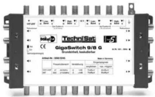
Basic unit
(for a maximum of 8 parties)
Art. No. 0000/3245
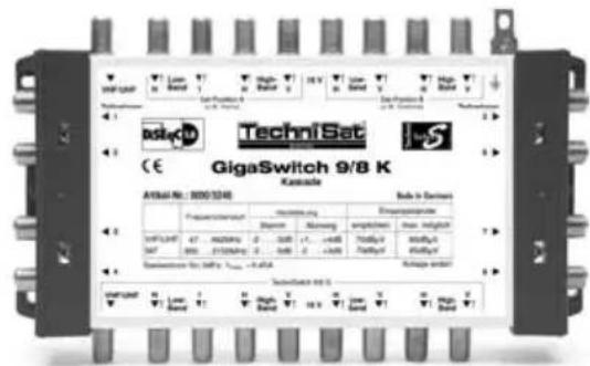
Cascade matrix
(for a maximum of 8 parties)
Art. No. 0000/3246
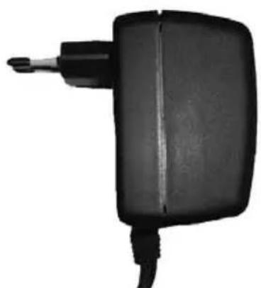
Mains power adapter
Art. No. 0000/3222
natural_image
Black handheld electronic device with a small tip and cable (no visible text or symbols)2 Safety notes
For your own protection, you should read the safety notes carefully before installing the equipment. The manufacturer accepts no liability for damage caused by inappropriate handling, or by ignoring the safety instructions.
Components should be mounted in a dry room, on a horizontal plane, consisting or flame-resistant materials.
When installing the equipment keep the electricity switched off.
Ensure the antenna installation is earthed.
Ensure the antenna installation is protected from lightning as per local regulations.
Ensure that you are in compliance with relevant European standards and VDE regulations, where applicable, with regard to electrical safety.
Y ou must comply with national regulations pertaining to broadcast reception installations.
Never open the housing of the equipment. Any repairs necessary should only be carried out by a qualified specialist. If the following apply, disconnect the equipment from the mains power supply, and call a qualified repair person:
the unit was subject to humidity, or water has run into the unit,
in case of malfunctions,
in case of severe external damage.
3 Installation
3.1 General
We recommend a star-shaped distribution, with the distributor being located either in the attic or near the centre of the building. If you are using a cascade matrix, please note Point 3.5.
Please ensure that the levels of the satellite signals fed into the system are approximately equal. This ensures that the very good decoupling characteristics are not limited.
As cables are very sensitive to damage, you should install these as late as possible during the building process. If possible, lay the cables inside a protective tube or pipe. Do not bend cables too sharply!
Install the equipment while the electricity is switched off, or disconnected.
3.2 Selecting the external unit/LNCs
Y ou may use Quatro or Dual-Output LNCs. Please note the maximum possible current strength for inputs, as per the technical data.
Quatro-Switch LNCs, Twin LNCs and Single Universal V/H LNCs are not suitable.
The current feeding the LNCs ia approx. 18V (load-dependant).
3.3 Cable
Because of the amplification provided by the units, you can use small-calibre, easy-to-use cables in spite of the higher damping this means.
When connecting the LNCs with the multi-switch, resp. several multi-switches with each other, we recommend the use of MULTYMEDIA cable (Art. No. 0001/3014).
we recommend you use mini coaxial cable to connect the multi-switch with the antenna sockets.
T o isntall longer sections of cable to connect to the antenna sockets, please use the low-damping co-axial cable CoaxSat 2150.
Damping values are specified in Point 6.
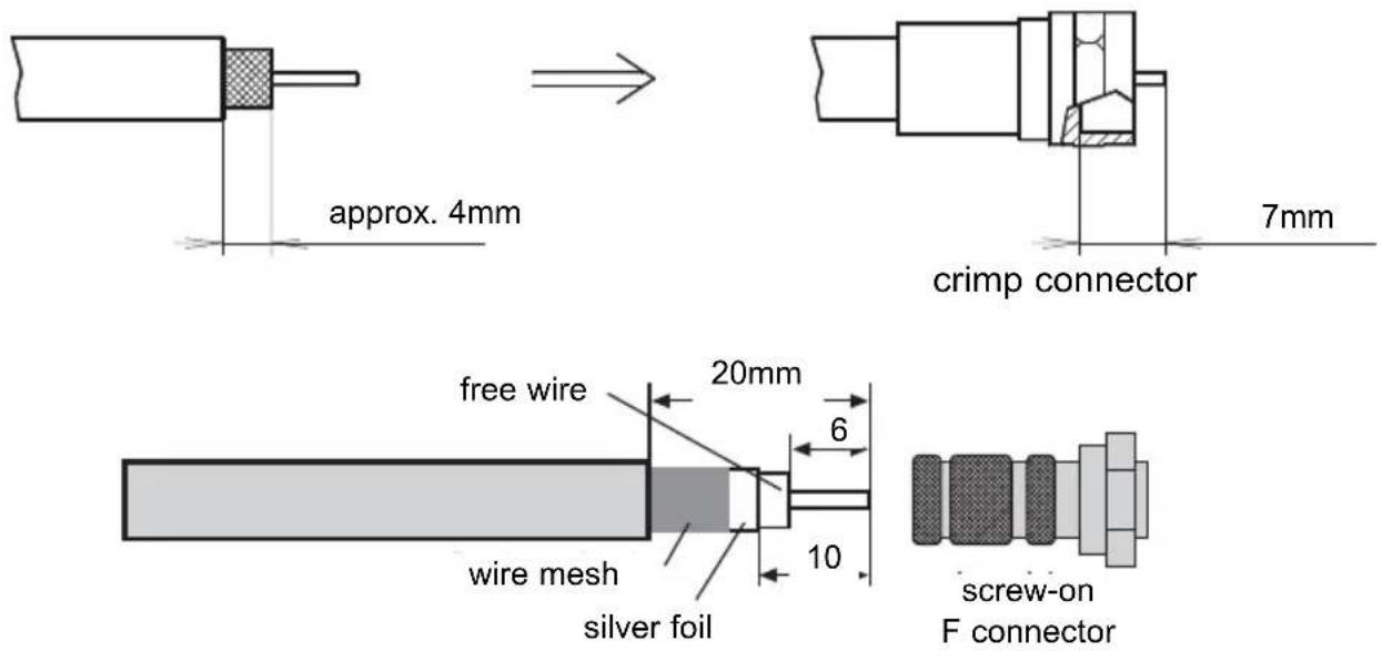
Please use crimp-type connectors wherever possible!
Insulation should be stripped from the cable as follows:
3.4 Antenna sockets
The participants should be connected to the system via antenna sockets (SV 500 or SVT 500). This ensures that terrestrial programmes can be received without the need for an additional socket, and equipment connected in this way is protected from extraneous interference.
3.5 Cascade
We recommend splitting the cascade distribution (star-shaped for each floor in the building, MULTYMEDIA cable between the multi-switches). This makes the laying of cables more efficient, with less possible confusion.
If you wish to distribute to 16 parties from a single central point (star-shaped distribution), connect the switches by means of quick-connecting F-connection adapters.
3.6 Energy-saving switch (use only when operating 9/8 G on its own!)
The terrestrial reception is supplied continuously via the mains adapter.
If the energy-saving switch is set to "on", the LNCs will only be fed if at least one receiver is switched on.
4 Installation hints
Check all cables for short circuits before making the connections, in the case of larger installations this can save a lot of time later.
Ensure that the connections from the LNC are not mixed up. To make things easier, we recommend you use the (multi-coloured) MULTYMEDIA cable, or mark the various cables with suitable multi-coloured marks.
Use single, uncut lengths of cable throughout. DVB signals are particularly susceptible to interference through the use of F-connectors.
Screw the F-connectors moderately tight.
Any outputs not used can, if you wish to achieve a particularly linear frequency distribution, be capped with a 75 Ohm terminal resistor.
Any inputs not used may not be capped with a terminal resistor.
The multi-switches can also be mounted in small distribution cabinets using hatclip fasteners.
Distribution of terrestrial programmes:
Ensure that the terrestrial signals fed into the system are of approximately equal strength.
A terrestrial pre-amplifier is not required.
5 Troubleshooting guide
| Problem Possible causes Solution | ||
| No reception on any polarisation plane. | Antenna position not cor-rect | Check the position of your antenna. Use the signal strength indicator of your receiver (transponder info) |
| Still no reception on any polarisation plane | Short circuit in LNC connection | Disconnect the branch connections on after the other to locate the short circuit |
| No reception, or wrong programmes, on individual polarisation planes | LNC connections swit-ched, or central wire in connection too short | Check on the allocation of cables and connectorsr.E.g. use a receiver to check on the signal direct-ly in the LNC connection. |
| Outputs of individual par-ties not functional | LNC voltage and/or swit-ching criteria of receiver incorrect | Try connecting the recei-ving unit to a different party output.Check the LNC power and the switching criteria with a measuring device, or try another receiving unit |
| No reception via receivers a cascade unit. | LNCs not feeding in Set swi-ch on 9/8 G to “Off” for energy saving | |
| Waves in terrestrial TV image | Input signal too strong Redu ce level(see Technical Data) | |
6 Technical Data
| Terrestrial 47 - 862 MHz,Satellite band: 950 - 2150 MHz | 9/8 G Cascade | 9/8 G + K | ||
| Terr. Sat. | Terr. Sat. | |||
| Throughput damping | 2 ... 3dB 2 | ... 5dB | ||
| Branch gain on 9/8K | 1 ... 4dB -2 | ... +3dB | ||
| Branch gain on 9/8G | -3 ... -1dB -2 | ... +3dB | -5 ... -4dB 3) | -4 ... -2dB 3) |
| Decoupling receiver outputs | >35dB | |||
| Input levels | ||||
| recommended 72dBμV 70dBμV | 70dBμV 75dBμV | |||
| maximum | 80dBμV 1) | 85dBμV 2) | 80dBμV 1) | 90dBμV 2) |
| Shielding | in acc. with EN50083-2/A1 (TechniSelect S) | |||
| Control | DiSEqC 1.0 or higher with U_ss>0,25V or Mini-DiSEqC or 11,5V...14V/16V...19Vund 0/22kHz ±4kHz | |||
| Mains adapter | Mains adapter supplied, 16V~, at full load 0,7A, stand-by <25mA | |||
| Power, requirements of mains adapter | 65mA | 190mA | ||
| max. possible to the LNCs | 635mA(protected against short circuit and overload) | 510mA(protected against short circuit and overload) | ||
| required by receiver | 60mA | |||
| Ambient temperature | -25...+55°C | |||
| Dimensions: WxHxD | 210x125x35 (mm) | |||
1) Relative to broad-band cable signal in BBC grid (36 TV signals, 24 FM programmes), CTB (72dB) / CSO (69dB), in case of terrestrial reception individual stations are often larger, but this is acceptable as long as they remain smaller than 90dBμV
2) in accordance with EN 50083-3: IMA3 35dB
3) In case of split cascading please also consider cable attenuation!
Installation for 8 parties/receivers
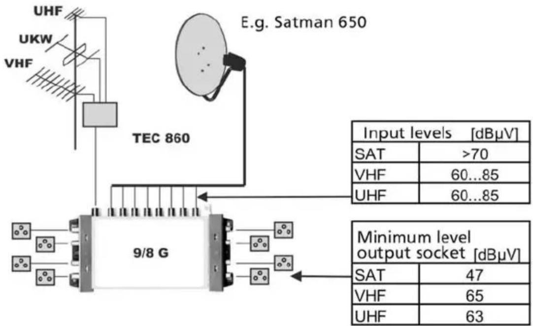
flowchart
graph TD
    A["UHF"] --> B["UKW"]
    B --> C["VHF"]
    C --> D["TEC 860"]
    D --> E["9/8 G"]
    E --> F["E.g. Satman 650"]
    F --> G["Sat: >70 dBμV"]
    F --> H["VHF: 60...85 dBμV"]
    F --> I["UHF: 60...85 dBμV"]
    E --> J["Minimum level output socket: [dBμV"]]
    J --> K["SAT: 47 dBμV"]
    J --> L["VHF: 65 dBμV"]
    J --> M["UHF: 63 dBμV"]
Installation for 16 parties/receivers
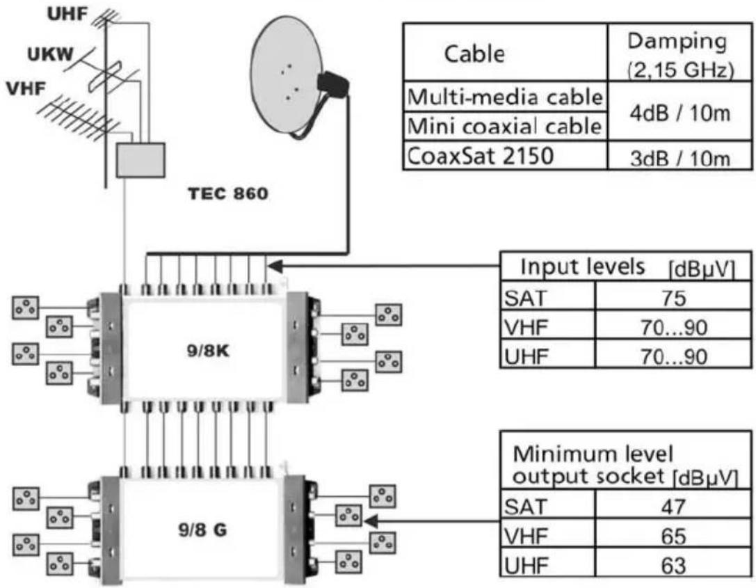
flowchart
graph TD
    A["TEC 860"] --> B["9/8K"]
    A --> C["9/8G"]
    B --> D["Cable"]
    B --> E["Multi-media cable"]
    B --> F["Mini coaxial cable"]
    B --> G["CoaxSat 2150"]
    C --> H["Input levels [dBμV"]]
    C --> I["Minimum level output socket [dBμV"]]
    D --> J["SAT: 75 dBμV"]
    E --> K["VHF: 70...90 dBμV"]
    F --> L["UHF: 70...90 dBμV"]
    G --> M["SAT: 47 dBμV"]
    G --> N["VHF: 65 dBμV"]
    G --> O["UHF: 63 dBμV"]
Your equipment is in accordance with CE, and complies with all relevant EU standards!
Subject to change, not responsible for printing errors. Correct as at 02/04
TechniSat and GigaSwitch are registered trademarks of
D- 54541 Daun, Germany
www.technisat.de
190204

- Uses
- Please note:
- Basic unit
- Cascade matrix
- Mains power adapter
- Safety notes
- Installation
- General
- Selecting the external unit/LNCs
- Cable
- Insulation should be stripped from the cable as follows:
- Antenna sockets
- Cascade
- Energy-saving switch (use only when operating 9/8 G on its own!)
- Installation hints
- Distribution of terrestrial programmes:
Brand : TECHNISAT
Model : GigaSwitch 9/8 K
Category : Uncategorized