
LSGT125-5M - Air conditioner Baxi - Free user manual and instructions
Find the device manual for free LSGT125-5M Baxi in PDF.


| Product Type | Split System Air Conditioner |
| Model | LSGT125-5M |
| Brand | Baxi |
| Cooling Capacity | 12000 BTU/h (approx.) |
| Heating Capacity | 12000 BTU/h (approx.) |
| Energy Efficiency Ratio (EER) | 3.5 (approx.) |
| Power Supply | 220-240V / 50Hz |
| Refrigerant | R32 |
| Indoor Unit Dimensions (WxHxD) | 800 x 280 x 220 mm (approx.) |
| Outdoor Unit Dimensions (WxHxD) | 750 x 550 x 300 mm (approx.) |
| Indoor Unit Weight | 10 kg (approx.) |
| Outdoor Unit Weight | 30 kg (approx.) |
| Noise Level (Indoor) | 25-40 dB(A) |
| Noise Level (Outdoor) | 50-55 dB(A) |
| Air Flow Rate | 400-600 m3/h |
| Remote Control | Yes |
| Timer Function | Yes |
| Sleep Mode | Yes |
| Filter Type | Washable Mesh Filter |
| Installation Type | Wall Mounted |
| Maintenance | Clean filter every 2 weeks; annual professional service |
| Compliance | CE, RoHS |
Frequently Asked Questions - LSGT125-5M Baxi
User questions about LSGT125-5M Baxi
0 question about this device. Answer the ones you know or ask your own.
Ask a new question about this device
Download the instructions for your Air conditioner in PDF format for free! Find your manual LSGT125-5M - Baxi and take your electronic device back in hand. On this page are published all the documents necessary for the use of your device. LSGT125-5M by Baxi.
USER MANUAL LSGT125-5M Baxi
natural_image
Line drawing of a screwdriver interacting with a device (no text or symbols present)natural_image
Diagram showing a screwdriver connecting to a wall-mounted electrical socket connected to a box (no text or symbols present)natural_image
Line drawing of a screwdriver interacting with a device (no text or symbols present)natural_image
Diagram showing a screwdriver connecting to a wall-mounted electrical socket connected to a box (no text or symbols present)Read and keep this manual.
PACKAGING CONTENT
| DESCRIPTION | FIGURE | SPECIFICATIONS |
| Wired control TXW1AC |  | Dimensions(hight/wide/dedepth): 120mmx120mmx20mm Weight: 168 g |
| 2 screws |  | M4x20 |
| User and Installation manual | [XABX] | |
| Long connection wiring |  | Length: 5000mm Weight: 99 g |
| Short connection wiring |  | Length: 50mm Weight: 10 g |
BUTTONS DESCRIPTION

ON/OFF button
Press- "ON/OFF" button to start or shutdown the unit.
- When the unit is running, users can regulate the operation mode, fan speed, setting temperature, special functions and other parameters on the wired controller.

flowchart
graph LR
    A["23 °C"] --> B["Timer Fan Swing Mode"]
    B --> C["23 °C"]
- When the unit is standby, the wire controller displays indoor ambient temperature (Room temp.), the other content are not displayed.

button-Temperature, time setting, function selection
- When the unit is running, press "▲" or "▼" button to increase or decrease the setting temperature by 1^ C.

flowchart
graph TD
    A["1st Temp: 23 °C"] --> B["Timer Fan: ON/OFF Swing Mode: Function Comfort"]
    B --> C["24 °C"]
    C --> D["Timer Fan: ON/OFF Swing Mode: Function Comfort"]
Under COOL, DRY, and HEAT modes, the setting temperature range is 16^ C-32 ^ C;
The controller will display" Set temp." to show the selling temperature;
- Under the function selection mode, press "▲" or "▼" button to select function;
- Under the timing mode, press "▲" or "▼" button to setting time.
Mode setting
When the unit is running, press "MODE" button, the running mode will switch according to the following order:

The initial setting temperature for each mode is 24^ C, and there is no temperature setting and automatic wind under FAN mode.
The setting of "Wind speed"
When the unit is running, press "Fan" button to switch fan speed in the following order:
3-gear of fan speed:

4-gear of fan speed:

flowchart
graph LR
    A["Auto"] --> B["(Low)"]
    B --> C["(Medium)"]
    C --> D["(High)"]
    D --> E["(Super-high)"]
    E --> F["Auto"]
In turbo mode, display fan speed (turbo+ highest fan speed icon).
The setting of "Swing"
- For the unit only has the function of up and down swing: When the unit is running, press "Swing" button to enter or cancel up and down swing. At the time of opening up and down swing "☐" is lighting. At the time of closed, swing icon will disappear. If the unit has positioning swing function, press "Swing" button to regulate the swing angle in the order:

flowchart
graph LR
    A["一"] --> B["八"]
    B --> C["八"]
    C --> D["i"]
    D --> E["i"]
    E --> F["彡"]
-
For the unit only has the function of left and right swing: when the unit is running, press "Swing" button lo enter or cancel left and right swing. At the time of opening left and right swing," [icon] is lighting. At the time of closed, swing icon will disappear. If the unit has positioning swing function, press "Swing" button lo regulate the swing angle in the order.
-
For the unit has the functions of left and right swing and up and down swing: Press "Swing" button, the swing mode will switch in the following cycle order:

flowchart
graph LR
    A["✓"] --> B["✓"]
    B --> C["✓"]
    C --> D["✓"]
    D --> E["✓"]
    E --> F["✓"]
The setting of "Comfort"
-
When the unit is running, press "Comfort" button to enter comfort function. The default setting temperature of COOL and DRY mode is 26 °C, HEAT mode 24 °C, setting temperature is adjustable. Fan speed is automatic and adjustable. The comfort function will be cancelled if the running mode is changed.
-
Press "Comfort button again to cancel comfort function."
"Timing" function
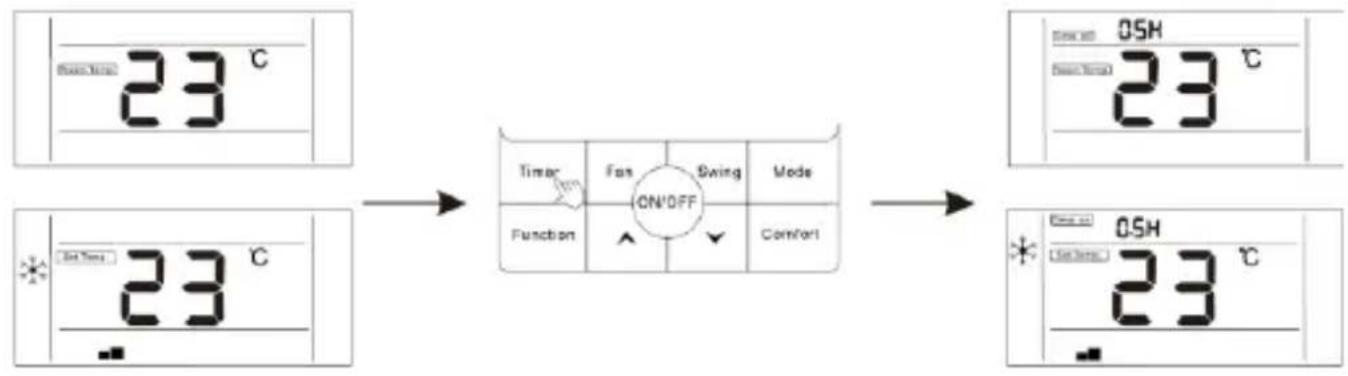
Users can set shutdown timing time when the unit is running, and set starting up timing time when the unit is stand by.
- Press "Timer" button when the unit is running, the wired controller will display "Time off" and users can set the shutdown timing time; when the unit is standby, the wired controller will display ", and users can set the starting-up timing time.
flowchart
graph LR
    A["23 °C Display"] --> B["CN/OFF Function"]
    B --> C["OSH 23 °C Display"]
    D["23 °C Display"] --> E["ON/OFF Function"]
    E --> F["OSH 23 °C Display"]
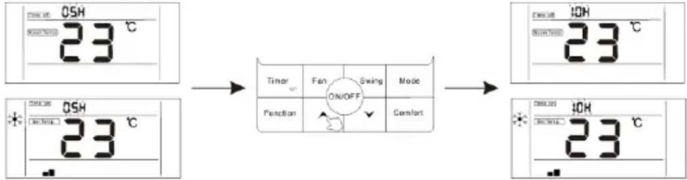
- After entering timing time setting interface, the default timing time is 0.5h, at this moment, press "▲" or "▼" button to regulate the timing time. If the button is not pressed for 10 seconds, the timing setting will be cancelled, and then return to the state of non-timing.
flowchart
graph LR
    A["0SH 23 °C"] --> B["ON/OFF"]
    B --> C["Timer Fan Swing Mode"]
    C --> D["Function Comfort"]
    D --> E["ON/OFF"]
- After the setting of timing, press "Timer" button again to confirm. The timing setting is successful and the time bar will stop blinking.

flowchart
graph LR
    A["ON/OFF ON/OFF 23 °C"] --> B["Timer: F=0, Swing: Off"]
    B --> C["Function: ✓"]
    C --> D["Comfort"]
    D --> E["ON/OFF ON/OFF 23 °C"]
- After the setting "Timer On" function, you can adjust the fan speed, running mode, set temperature, and swing angle. If there is no operation for 10 seconds, standby screen will be displayed.

flowchart
graph TD
    A["Start: 23°C"] --> B["Timer Fan ON/OFF"]
    B --> C["Function"]
    C --> D["ON/OFF Mode"]
    D --> E["Timer Fan ON/OFF"]
    E --> F["Function"]
    F --> G["ON/OFF Mode"]
    G --> H["End"]
-
Timing range: 0.5-24 hours. Press "▲" or "▼" button once, the timing time will increase or decrease by 0.5 hours. When the timing time is more than 10 hours, press "" or "" button once, the timing time will increase or decrease by 1 hour.
-
Press "Timer" button or "ON/OFF" button to exit TimerON or TimerOFF.
OPTIONAL FUNCTIONS
The wired controller is for the general-purpose, specific functions of the controller are subject to the functions of your air conditioning unit. Note: In the interface of function setting, press any button such as Timer, Fan, Swing, Mode, ON/OFF, and Comfort to exit the interface and conventional operation interface will display. If there is no operation for 10S, you can exit the interface.
Enter function: Press function button to enter function selection interface, press "
▲" or "▼" to select a function, and the corresponding icon will flash, press "function" button again to confirm the function.
Cancel function: Press function button lo enter function selection interface, press "
▲ " or "▼" lo select function and !he corresponding icon will flash, press "function" button again to cancel the function.
The setting of "Turbo" function
Turbo function: The fan speed will be ultra-high in turbo mode and users can achieve rapid cooling or heating effect.
Open turbo function:
-
When the unit is running in cooling or healing mode, press "Function" key to enter the interface of function selection.
-
Press "▲" or "▼" button to switch to turbo function, at this moment, " " icon is flashing.

- Press "Function" button to confirm turbo function, at this moment, icon " ", fan speed display is (Turbo and speed speed icons).

flowchart
graph TD
    A["Timer"] --> B["ON/OFF"]
    B --> C["Status"]
    C --> D["23 °C"]
    D --> E["Function"]
    E --> F["ON/OFF"]
    F --> G["Status"]
    G --> H["23 °C"]
    H --> I["Comfort"]
    I --> J["Comfort"]
Cancel turbo function:
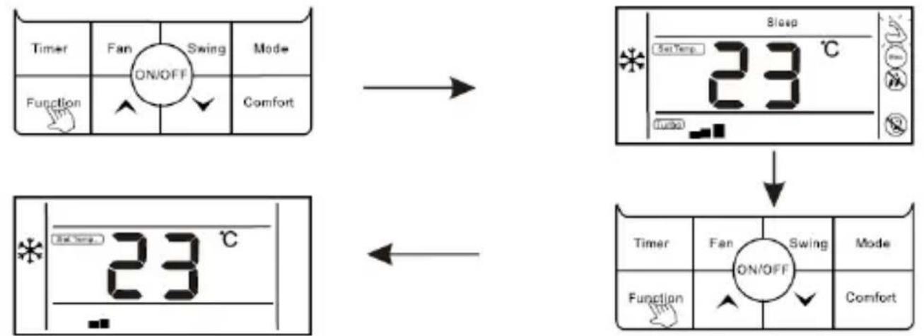
- When turbo function is opened, press "Function" button to enter the interface of function selection.
- Press "▲" or "▼" switch to strong function, at this moment, icon "💡" is flashing, press "Function" button to cancel strong function, and strong icon would not display.
flowchart
graph TD
    A["Timer"] --> B["Fan ON/OFF"]
    B --> C["Swing Mode"]
    C --> D["Function ↑"]
    D --> E["Comfort ↓"]

    F["Sleep"] --> G["23 °C"]
    G --> H["Reset Temp"]

    I["Timer"] --> J["Fan ON/OFF"]
    J --> K["Swing Mode"]
    K --> L["Function ↑"]
    L --> M["Comfort ↓"]
Note: The unit without turbo function can also set turbo function on the wired controller, the performance is high fan speed, but “ ” icon and “ Turbo ” icon do will not display.
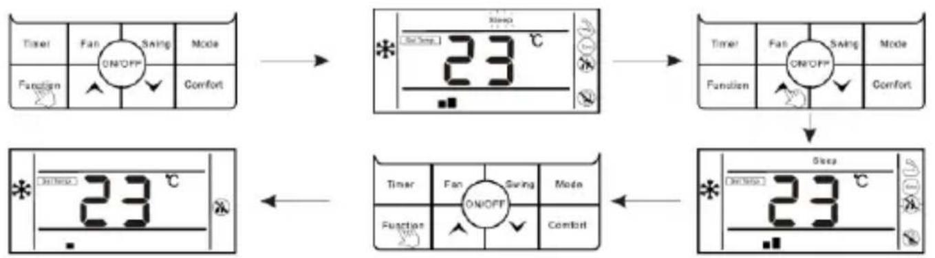
The setting of "Sleep" function
Sleep function: Make indoor unit will run according to pre-set sleep temperature curve, which creates a comfortable sleep environment and improves sleep quality.
Enter sleep function:
-
In the stale of running, press "Function" button to enter the interface of function selection.
-
Press "▲" or "▼" button to switch to sleep function, "Sleep" icon is flashing at this moment.
- Press" Function" button to open sleep function, at this moment, icon "Sleep" is lighting.

flowchart
graph TD
    A["Timer"] --> B["Fan"]
    B --> C["ON/OFF"]
    C --> D["Swing"]
    D --> E["Comfort"]
    F["Function"] --> G["Switch"]
    G --> H["Comfort"]
    I["Set Temp"] --> J["23 °C"]
    J --> K["Sleep"]
    K --> L["ON/OFF"]
    L --> M["Function"]
    N["Timer"] --> O["Fan"]
    O --> P["ON/OFF"]
    P --> Q["Swing"]
    Q --> R["Mode"]
    S["Function"] --> T["Switch"]
    T --> U["ON/OFF"]
    U --> V["Comfort"]
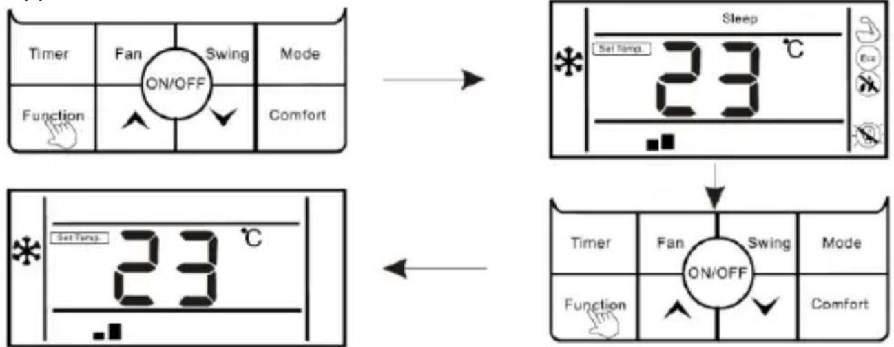
Cancel "sleep" function:
- When sleep function is opened, press "Function" button to enter the interface of function selection.
- Press "▲" or "▼" button to switch to sleep function, icon Sleep is flashing.
- Press "Function" button again to cancel sleep function.

flowchart
graph TD
    A["Timer"] --> B["Fan"]
    B --> C["ON/OFF"]
    C --> D["Swing"]
    D --> E["Comfort"]
    F["Function"] --> G["Switch"]
    G --> H["Comfort"]
    I["Set Temp"] --> J["23 °C"]
    K["Sleep"] --> L["23 °C"]
    M["ON/OFF"] --> N["Comfort"]
The setting of "ECO" function
Enter ECO function:
- Press "Function" button to enter the interface of function selection.
-
Press “▲” or “▼” button lo switch lo ECO function, at this moment, “Eco” icon is flashing.
-
Press "Function" button again to confirm ECO function, at this moment, "ECO" icon is flashing.

flowchart
graph TD
    A["Timer Fan Swing Mode"] --> B["23°C Sleep"]
    C["Function ↑ ✓ Comfort"] --> B
    B --> D["Timer Fan Swing Mode"]
    E["23°C"] --> F["Timer Fan Swing Mode"]
    G["Function ↑ ✓ Comfort"] --> H["23°C Sleep"]
Cancel ECO function:
- Press "Function" button to enter the interface of function selection.
- Press "▲" or "▼" button to switch to ECO function, at this moment Icon is flashing.
- Press "Function" button again to cancel ECO function.

flowchart
graph TD
    A["Timer"] --> B["Fan"]
    B --> C["ON/OFF"]
    C --> D["Swing"]
    D --> E["Comfort"]
    F["Function"] --> G["Set Temp"]
    G --> H["23 °C"]
    H --> I["ON/OFF"]
    I --> J["Timer"]
    J --> K["Fan"]
    K --> L["SWing"]
    L --> M["Mode"]
    N["Comfort"] --> O["SET Temp"]
    O --> P["23 °C"]
    P --> Q["ON/OFF"]
    Q --> R["Timer"]
    R --> S["Fan"]
    S --> T["Swing"]
    T --> U["Mode"]
    V["Comfort"] --> W["SET Temp"]
    W --> X["23 °C"]
    X --> Y["ON/OFF"]
The setting of "Mildew-proof" function
Mildew-proof function: After shutdown, the air conditioner would automatically dry the moisture in the evaporator of indoor unit, so as to avoid mildewing.
Enter mildew-proof function:
- Under COOL and DRY mode, press "Function" button lo enter the interface of function selection.
- Press "▲" or "▼" button to switch to the mildew-proof function setting interface, at this moment, icon "●" is flashing.
- Press "Function" button again to enter mildew-proof function, icon "OK" is lighting.
flowchart
graph TD
    A["Timer Fan Swing Mode"] --> B["23 °C"]
    C["Function Comfort"] --> B
    D["Timer Fan Swing Mode"] --> E["23 °C"]
    F["Function Comfort"] --> E
    G["Sleep 23 °C"] --> H["23 °C"]
Cancel fungus-proof function:
- When mildew proof function is ON, press "Function" button to enter the interface of function selection.
- Press "▲" or "▼" button to mildew proof function, icon "×" is flashing.
- Press "Function" button again to cancel mildew proof function, icon will " disappear.

flowchart
graph TD
    A["Timer"] --> B["Fan"]
    B --> C["ON/OFF"]
    C --> D["Swing"]
    D --> E["Comfort"]
    F["Function"] --> G["Switch"]
    G --> H["Comfort"]
    I["Set Temp"] --> J["23 °C"]
    K["Sleep"] --> L["23 °C"]
    M["ON/OFF"] --> N["Comfort"]
    O["Function"] --> P["Switch"]
    Q["Comfort"] --> R["Comfort"]
The setting of "Light Sensation" function
Light sensation function: Detect the On and Off of indoor lamplight and switch to low fan speed when the lamplight is off, which can reduce the noise and create a comfortable sleep environment for users.
Enter light sensation function:
- In the state of running, press "Function" button to enter the interface of function selection.
- Press "▲" or "▼" to switch to light sensation function, icon "☐" is flashing.
- Press Function button again to enter light sensation function, at this moment, icon" " is lighting.
- When light sensation function is on, if the indoor lamplight is OFF and lasts for 20 minutes, the unit will automatically enter sleep mode. If the indoor lamplight is ON, and lasts for 20 minutes, the unit will cancel sleep mode and run according to the setting fan speed.

flowchart
graph TD
    A["Timer"] --> B["Fan ON/OFF"]
    B --> C["Sweep Mode"]
    C --> D["Function ↑"]
    D --> E["Comfort ↓"]

    F["* 23 °C"] --> G["ON/OFF"]
    G --> H["Speed 23 °C"]

    I["Timer"] --> J["Fan ON/OFF"]
    J --> K["Sweep Mode"]
    K --> L["Function ↑"]
    L --> M["Comfort ↓"]

    N["* 23 °C"] --> O["ON/OFF"]
    O --> P["Sweep Mode"]
    P --> Q["Function ↑"]
    Q --> R["Comfort ↓"]
Cancel light sensation:
- When light sensation function is on, press "Function" button to enter the interface of function selection.
- Press "▲" or "▼" button to switch to light sensation function, icon is flashing.
- Press "Function" button again to cancel light sensation function, icon "→" will disappear.
flowchart
graph TD
    A["Timer"] --> B["Fan ON/OFF"]
    B --> C["Swing"]
    C --> D["Comfort"]
    E["Function"] --> F["Set Temp. 23 °C"]
    F --> G["Sleep"]
    G --> H["23 °C"]
    I["ON/OFF"] --> J["Action"]
    J --> K["Reset"]
    L["Timer"] --> M["Fan"]
    M --> N["Swing"]
    N --> O["Comfort"]
    P["Function"] --> Q["Action"]
    Q --> R["Reset"]
The setting of "Clean" function
Clean function: The air conditioner can clean the evaporator automatically, which can not only keep air fresh, but also reduce the recession of cooling effect.
Enter clean function:
- In the state of standby, press "Function" button to enter the interface of function selection, icon " " is flashing.
- Press "Function" button again to confirm clean function, at this moment, icon "Clean" is lighting.
- When the unit is performing clean function, the wired controller will keep displaying icon "", until it is finished.
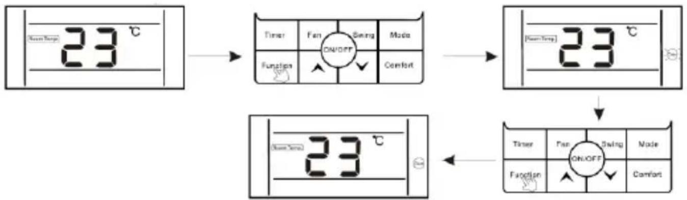
flowchart
graph TD
    A["Sensor Input: 23 °C"] --> B["Timer Fan Swing Mode"]
    B --> C["Function ↑ ✓ Comfort"]
    C --> D["ON/OFF: 23 °C"]
    D --> E["Timer Fan Swing Mode"]
    E --> F["Function ↑ ✓ Comfort"]
DISPLAY PROMPT FUNCTIONS
"WIFI" function display
If the unit is equipped with a WIFI function module, the icon " 🔊" is lighting on wired controller.
If the unit is not equipped with a WIFI function module, the icon " 🔺 " does not display.
"Shielding" function display
When unit is locked by centralized control, the wired controller will display "☐".
"Mute" function display
When the unit enter silent function, display " 🔍" icon, when silent function is cancelled, the icon does not display.
Note: The unit without silent function can also set silent through wired controller, but it shows in the way of low wind grade, but " 🔍" does not display.
"Oil Return / Defrost" function display
When the unit is running in the state of Oil Return or Defrost, " " icon is lighting on wire controller.
When the unit has finished Oil Return or Defrost process," 🔊 " icon does not display.
"Filter Screen Clean" function display
Filter screen cleaning reminder function: The unit can record its running time, when reaching the time set by the user, it will remind the user to clean the filter screen, so as to avoid prolonged cleaning and filter screen blockage, which can result in poor heating/cooling effect, abnormal protection, bacterial breeding, and other problems. When the running time reaches the filter screen cleaning reminder time set by a user, the unit will give out a reminder of filter screen cleaning, wired controller displays " ” Icon, reminding the user to clean filter screen. At this moment, long press "Timer" button for 5S to cancel the reminder, then the icon does not display. A filter screen cleaning reset signal is sent to the unit.
Celsius and Fahrenheit switching display
When users set Celsius to be valid, the wired controller will display Celsius temperature. When users set Fahrenheit to be valid, the wired controller will display corresponding Fahrenheit temperature synchronously.
"Child Lock" function display
Press both " " or " " buttons for more than 5S to enter locking, the controller
will display “☐”. In the state of locking, operations on the wired controller are disabled (but remote control receiving is valid). The method of unlocking: Press both " " or " " buttons for more than 5S or power off the unit to release the locking
(" does not display).
Remote control function
The wired controller can receive remote control commands and update the current status.
Start-up the unit with remote controller, wired controller work in accordance with the state set on the remote controller and displays corresponding working mode.
Room temperature sensor equipped on the wired controller
When the wire controller is equipped with a room temperature sensor and the sensor is not damaged, it is default that the ambient temperature detected by the sensor on the controller and the temperature value will be sent to the main PCB of the unit.
If the wire controller is not equipped with a room temperature sensor or the sensor is damaged, the room temperature will be detected by the temperature sensor of the unit itself.
Fault display
When the unit has fault, the time bar will directly display the fault code and flash, the display mode is Ex: MM (MM is the fault code, please read the corresponding product manual).
Use a flathead screw driver to pry the bottom groove of the wire controller lightly (too much force would damage circuit board), pry rotationally to open the back cover.

natural_image
Line drawing of a screwdriver inserting into a device (no text or symbols)As shown in Fig.3, fix 4 * 20mm screws provided together with the back cover on 8 6 box, then pass lead wires through the back cover.
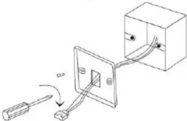
natural_image
Diagram showing a screwdriver connecting to a wall-mounted electrical socket connected to a box (no text or symbols present)After connecting the connecting wire to the main body of the wire controller, install main body part according to the following steps:
1). Push the upper part of main body into the clip.
2). Use the force of inclined top to install the lower part of main body (horizontal installation is prohibited, which is easy to damage the structural slot).

| Connect the long cable to the wired control cable | Connect the other side of the long cable with short one | Connect the other side of the short cable (white connector) to the PCB |
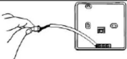 |  | 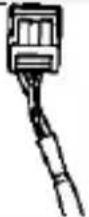 |
R32 MONO FLOOR/CEILING AND MONO CASSETTE INDOOR UNITS → RZGN(C/K)(35/50/70/100/120/140/160)
- In case of duct units, wired control is supplied as standard.
- Connect the white control connector to the "CN7" connector of the indoor unit PCB as shown in the following schema:

flowchart
graph TD
    subgraph Power
        A["AC_N"] --> B["XE"]
        C["AC_L"] --> D["L_R"]
        E["RD"] --> F["BU"]
        G["L"] --> H["N"]
        I["N"] --> J["A"]
        K["A"] --> L["B"]
        M["B"] --> N["Communication"]
    end

    subgraph Communication
        O["Step motor M2"] --> P["Pump M3"]
        Q["Step motor M4"] --> R["UP_DW"]
        S["Step motor M7"] --> T["Control PCB"]
        U["Step motor M9"] --> V["Control PCB"]
        W["Step motor M10"] --> X["Control PCB"]
        Y["Step motor M11"] --> Z["Control PCB"]
        AA["Step motor M12"] --> AB["Control PCB"]
        AC["Step motor M13"] --> AD["Control PCB"]
        AE["Step motor M14"] --> AF["Control PCB"]
        AG["Step motor M15"] --> AH["Control PCB"]
        AI["Step motor M16"] --> AJ["Control PCB"]
    end

    subgraph Power_Temperature
        AK["Room Temp"] --> AL["CN1"]
        AM["Evap Temp"] --> AN["CN11"]
        AO["Water Pump"] --> AP["CN6"]
        AQ["Power PCB"] --> AR["CN3"]
    end

    subgraph Communication
        AS["Power"] --> AT["L"]
        AU["Communication"] --> AV["N"]
        AW["Power"] --> AX["A"]
        AY["B"]
    end

    subgraph Power_Control
        AZ["Wired Control"] --> BA["CN2"]
        BB["Power PCB"] --> BC["DNAN"]
        BD["Fan Motor"] --> BE["M1"]
    end

    subgraph Communication_Control
        BF["Control PCB"] --> BG["UP_DW"]
        BH["Control PCB"] --> BI["CN9"]
        BJ["Control PCB"] --> BK["CN16"]
    end

    subgraph Power_Control
        BL["Power PCB"] --> BM["CN3"]
    end

    subgraph Communication_Control
        BN["Power"] --> BO["L"]
        BP["Communication"] --> BQ["A"]
        BR["B"]
    end

    subgraph Power_Control
        BS["Power PCB"] --> BT["CN3"]
    end

    subgraph Communication_Control
        BU["Power PCB"] --> BV["CN3"]
    end
R32 MULTI CASSETTE INDOOR UNITS → LSGNK (25/35/50)-XM
- In case of duct units, wired control is supplied as standard.
- Connect the white control connector to the "CN8" connector of the indoor unit PCB as shown in the following schema:

flowchart
graph TD
    A["Power"] --> B["Communication"]
    B --> C["AC_L3"]
    C --> D["Transformer"]
    D --> E["AC_N"]
    D --> F["CN4"]
    D --> G["CN1"]
    D --> H["CN13"]
    H --> I["Panel receiver"]
    I --> J["CN8"]
    I --> K["Wired control"]
    K --> L["CN11"]
    K --> M["CN9"]
    K --> N["CN7"]
    K --> O["Evap Temp"]
    P["Drain pump"] --> Q["M2"]
    R["Fan motor"] --> S["M1"]
    T["Step motor"] --> U["M3"]
    V["Float switch"] --> W["CN12"]
    X["Room Temp"] --> Y["Tao"]
    Z["Timer"] --> AA["Fan"]
    AB["Fan OFF"] --> AC["Swing"]
    AD["Mode"] --> AE["Comfort"]
ON/OFF-Taste
natural_image
Line drawing of a screwdriver inserting into a device component (no text or symbols)natural_image
Diagram showing a tool interacting with a wall-mounted socket connected to a box (no text or symbols present)flowchart
graph TD
    subgraph Power
        A["AC_N"] --> B["XE"]
        C["AC_L"] --> D["L_R"]
        E["RD"] --> F["BU"]
        G["L"] --> H["N"]
        I["A"] --> J["B"]
        K["Power"] --> L["Communication"]
    end

    subgraph Communication
        M["Step motor M2"] --> N["CN1"]
        O["Step motor M4"] --> P["CN3"]
        Q["Control PCB CN8"] --> R["CN12"]
        S["Control PCB CN13"] --> T["CN11"]
        U["Control PCB CN14"] --> V["CN1"]
        W["Wired Control"] --> X["UP_DW"]
        Y["Power PCB CN3"] --> Z["CN6"]
        AA["Power PCB CN10"] --> AB["SW1"]
        AC["Power PCB CN15"] --> AD["SW2"]
        AE["Power PCB CN16"] --> AF["CN7"]
        AG["Power PCB CN17"] --> AH["CN8"]
        AI["Power PCB CN18"] --> AJ["CN9"]
        AK["Power PCB CN19"] --> AL["CN10"]
        AM["Power PCB CN20"] --> AN["DNAN"]
        AO["Power PCB CN21"] --> AP["DNAN"]
        AQ["Power PCB CN22"] --> AR["DNAN"]
        AS["Power PCB CN23"] --> AT["DNAN"]
        AU["Power PCB CN24"] --> AV["DNAN"]
        AW["Power PCB CN25"] --> AX["DNAN"]
        AY["Power PCB CN26"] --> AZ["DNAN"]
        BA["Power PCB CN27"] --> BB["DNAN"]
        BC["Power PCB CN28"] --> BD["DNAN"]
        BE["Power PCB CN29"] --> BF["DNAN"]
        BG["Power PCB CN30"] --> BH["DNAN"]
        BI["Fan Motor"] --> BJ["M1"]
        BK["Fan Motor"] --> BL["M2"]
        BM["Fan Motor"] --> BN["M3"]
    end

    subgraph Control
        O
        P
        Q
        R
        S
        T
        U
        V
        W
        X
        Y
        Z
        AA
        AB
        AC
        AD
        AE
        AF
        AG
        AH
        AI
        AJ
        AK
        AL
        AM
        AN
        AO
        AP
        AZ
        BA
    end

    subgraph Control PCB
        R
        S
        T
        U
        V
        W
        X
        Y
        Z
    end

    subgraph Power_Pack
        M
        N
        O
        P
    end

    subgraph Power_Pack_Circuit
        P
        Q
        R
    end

    subgraph Power_Pack_Accumulation
        M1
        N1
        O1
        P1
    end

    subgraph Power_Pack_Bulking
        M2
        N2
        O2
    end

    subgraph Power_Pack_Bulking_Racking_1
        M3
        N3
        O3
    end

    subgraph Power_Pack_Bulking_Racking_Racking_2
        M4
        N4
        O4
    end

    subgraph Power_Pack_Bulking_Racking_Accumulation_1
        M5
        N5
        O5
    end

    subgraph Power_Pack_Bulking_Racking_Accumulation_Accumulation_Bccumulation_1
        M6
        N6
        O6
    end

    subgraph Power_Pack_Bulking_Racking_Accumulation_Bccumulation_Bccumulation_Accumulation_Circumulation_1
        M7
        N7
        O7
    end

    subgraph Power_Pack_Bulking_Racking_Bccumulation_Racking_Bccumulation_Bccumulation_Bccumulation_Circumulation_1
        M8
        N8
        O8
    end

    subgraph Power_Pack_Bulking_Racking_Bccumulation_Racking_Bccumulation_Bccumulation_Bccumulation_Circumulation_1
        M9
        N9
        O9
    end

    subgraph Power_Pack_Bulking_Racking_Bccumulation_Racking_Bccumulation_Racking_Bccumulation_Bccumulation_Bccumulation_Circumulation_1
        M10
        N10
        O10
    end

    subgraph Power_Pack_Bulking_Racking_Bccumulation_Racking_Bccumulation_Bccumulation_Bccumulation_Bccumulation_Circumulation_1
        M11
        N11
        O11
    end

    subgraph Power_Pack_Bulking_Racking_Bccumulation_Racking_Bccumulation_Bccumulation_Bccumulation_Bccumulation_Bccumulation_Circumulation_1
        M12
        N12
        O12
    end

    subgraph Power_Pack_Bulking_Racking_Bccumulation_Racking_Bccumulation_Bccumulation_Bccumulation_Bccumulation_Bccumulation_Circumulation_1
        M13
        N13
        O13
    end

    subgraph Power_Pack_Bulking_Racking_Bccumulation_Racking_Bccumulation_Bccumulation_Bccumulation_Bccumulation_Bccumulation_Circumulation_1
        M14
        N14
        O14
    end

    subgraph Power_Pack_Bulking_Racking_Bccumulation_Racking_Bccumulation_Bccumulation_Bccumulation_Bccumulation_Bccumulation_Circumulation_1
        M15
        N15
        O15
    end

    subgraph Power_Pack_Bulking_Racking_Bccumulation_Racking_Bccumulation_Bccumulation_Bccumulation_Bccumulation_Bccumulation_Circumulation_1
        M16
        N16
        O16
    end

    subgraph Power_Pack_Bulking_Racking_Bccumulation_Racking_Bccumulation_Bccumulation_Bccumulation_Bccumulation_Bccumulation_Circumulation_1
        M17
        N17
        O17
    end

    subgraph Power_Pack_Bulking_Racking_Bccumulation_Racking_Bccumulation_Bccumulation_Bccumulation_Bccumulation_Circumulation_1
        M18
        N18
        O18
    end

    subgraph Power_Pack_Bulking_Racking_Bccumulation_Racking_Bccumulation_Bccumulation_Bccumulation_Bccumulation_Circumulation_1
        M19
        N19
        O19
    end

    subgraph Power_Pack_Bulking_Racking_Bccumulation_Racking_Bccumulation_Bccumulation_Bccumulation_Bccumulation_Circumulation_1
        M20
        N20
        O20
    end

    subgraph Power_Pack_Bulking_Racking_Bccuancy_Racking_Bccuancy_Racking_Bccuancy_Racking_Bccuancy_Bccuancy_Circuancy_Rackung_1
            M21
            N21
            O21

    end
flowchart
graph TD
    A["Timer Fan Swing Mode"] --> B["Function ON/OFF Comfort"]
    B --> C["23 °C Sleep"]
    C --> D["ON/OFF Timer Fan Swing Mode"]
    D --> E["Action: Forward to Temperature"]
natural_image
Line drawing of a screwdriver inserting into a device component (no text or symbols)natural_image
Diagram showing a screwdriver connecting to a wall-mounted switch and connected to a box (no text or symbols present)


- ON/OFF button
- button-Temperature, time setting, function selection
- Mode setting
- The setting of "Wind speed"
- The setting of "Swing"
- The setting of "Comfort"
- "Timing" function
- OPTIONAL FUNCTIONS
- The setting of "Turbo" function
- Open turbo function:
- Cancel turbo function:
- The setting of "Sleep" function
- Enter sleep function:
- The setting of "ECO" function
- Cancel ECO function:
- The setting of "Mildew-proof" function
- The setting of "Light Sensation" function
- Cancel light sensation:
- The setting of "Clean" function
- Enter clean function:
- DISPLAY PROMPT FUNCTIONS
- "WIFI" function display
- "Shielding" function display
- "Mute" function display
- "Oil Return / Defrost" function display
- "Filter Screen Clean" function display
- Celsius and Fahrenheit switching display
- "Child Lock" function display
- Remote control function
- Room temperature sensor equipped on the wired controller
- Fault display
- R32 MONO FLOOR/CEILING AND MONO CASSETTE INDOOR UNITS → RZGN(C/K)(35/50/70/100/120/140/160)
- R32 MULTI CASSETTE INDOOR UNITS → LSGNK (25/35/50)-XM
- ON/OFF-Taste
Brand : Baxi
Model : LSGT125-5M
Category : Air conditioner