
ATB20STP - Subwoofer Axton - Free user manual and instructions
Find the device manual for free ATB20STP Axton in PDF.


| Type of Product | Subwoofer |
| Brand | Axton |
| Model | ATB20STP |
| Dimensions (approx.) | 300 x 300 x 350 mm |
| Weight (approx.) | 8 kg |
| Power Output (RMS) | 100 W |
| Impedance | 4 ohms |
| Frequency Response | 20 Hz - 200 Hz |
| Input Connections | RCA line input |
| Protection Features | Overload and thermal protection |
| Power Supply | AC 220-240 V, 50/60 Hz |
| Included Accessories | Power cable, user manual |
| Enclosure Type | Bass-reflex (ported) |
| Driver Size | 8 inch |
| Phase Control | Yes, 0/180 degree switch |
| Auto Standby | Yes |
| Maintenance | Wipe with a dry cloth; do not use solvents |
| Safety Instructions | Do not expose to moisture or heat sources |
| Repairability | Spare parts available from manufacturer |
Frequently Asked Questions - ATB20STP Axton
User questions about ATB20STP Axton
0 question about this device. Answer the ones you know or ask your own.
Ask a new question about this device
Download the instructions for your Subwoofer in PDF format for free! Find your manual ATB20STP - Axton and take your electronic device back in hand. On this page are published all the documents necessary for the use of your device. ATB20STP by Axton.
USER MANUAL ATB20STP Axton
natural_image
Close-up of a black cylindrical electronic device with a labeled control panel (no visible text or symbols on the device itself)8"/20 CM
ACTIVE
SUBWOOFER

natural_image
Abstract logo design with blue and white geometric shapes on black background (no text or symbols)EVOLUTION
SERIES

natural_image
Abstract digital visualization with glowing blue light streaks and a bright central light source (no text or symbols)Thank you and congratulations on your purchase of the AXTON AXB20STP. This active subwoofer system exclusively uses very high quality parts and components. As with all high-quality car audio components, professional installation is highly recommended. If you plan on installing this active subwoofer by yourself, please read the following installation guide carefully, before you attempt the installation. You should retain this manual, the packing and the purchasing receipt for future reference. For any further additional information about mounting, connecting or adjusting this subwoofer system, please contact your AXTON dealer.
UNPACKING THE SYSTEM
Carefully remove all parts from the giftbox and check whether they are in good undamaged condition, and match with the set contents listed below:
■ AXB20STP active subwoofer
■ High level input plug
■ Owner's manual
Please contact your authorized AXTON dealer, if the content of this set is incomplete, or parts of it show signs of transport damage.
SPECIFICATIONS
■ 8" / 20 cm active trunk box subwoofer
■ Frequency response: 25 – 100 Hz
■ 90 W rms x 1 @ 4 ohms (< 1.0 % THD / 14.4V)
■ 110 W max. x 1 @ 4 ohms (< 10 % THD / 14.4V)
■ Variable lowpass filter: 50 – 150Hz / 12 dB/oct.
■ Switchable Bass-Boost: 0 dB / 6 dB
■ RCA, adjustable input sensitivity: 165 mV – 5 V
■ High-Level, adjustable input sensitivity: 1.0 V – 10 V
■ Signal to noise ratio: > 90 dB
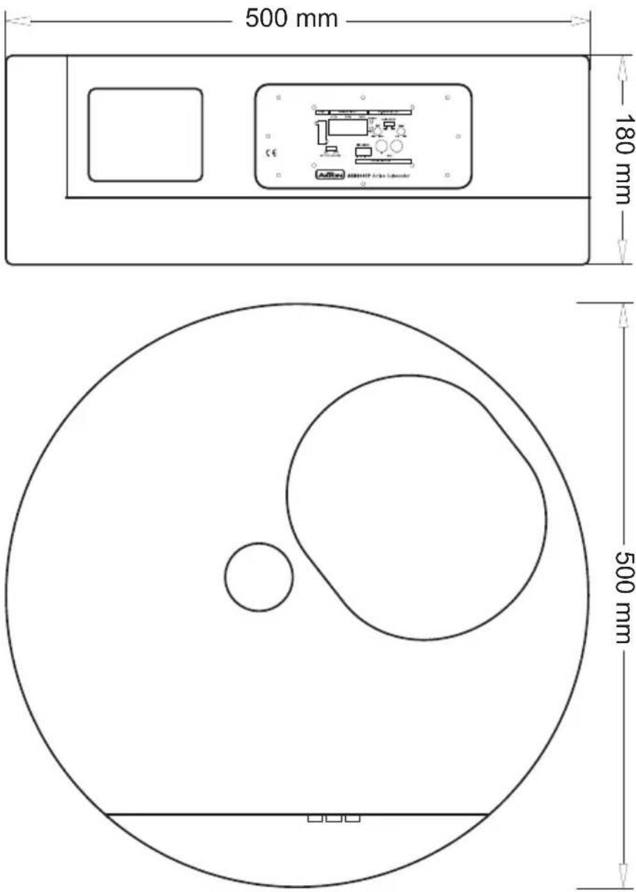
■ Dimensions DxH: 500 x 180 mm
■ Net Weight: 10.5 kg
- This unit is designed to be used in a vehicle with a 12V battery and negative ground.
- Before any wiring, always remove the negative terminal of the battery to prevent short-circuiting. This is also the last lead to be (re-)connected.
- Do not disassemble or alter the unit in any way, because that will void your warranty. Do not attempt to repair or to service the unit yourself, but contact an authorized AXTON dealer instead.
- Use only original accessories which are designed and manufactured for the unit, otherwise you will risk damage. Install the unit according to the mounting manual and use only the supplied mounting accessories. The forces of acceleration for accidents are sometimes huge. Heavy objects may pose a risk for the driver and the passengers of the car, during an accident.
- Protect the unit from water and other liquids, which can enter the casing. A short circuit or even fire could be the result.
- Before you replace a defective fuse, try to find the cause for the short circuit. Please pay attention to the cables of the power supply! If the short circuit doesn't result from a failure of the power supply or wiring, you can replace the defective fuse with a new one of identical value. If the short-circuit still exists, please contact an authorized AXTON dealer.
- Be careful not to drain the car battery while using the unit when the car engine is turned off. Because the unit uses a considerable amount of energy and the battery will be charged only while the engine is running, it might happen that the battery will discharge to a point where it's not longer possible to start the engine.
- If your car is parked in direct sunlight and there is a considerable rise in temperature inside the car, allow the unit to cool off before operation.
- The amplifier module employs a protection circuit to protect the transistors and the woofer if the amplifier malfunctions. The amplifier's protection circuitry will shut-off the amplifier in case of short-circuit, overload or DC offset at the speaker outputs or in case of overheat. In case the cause for protection shut-off has been eliminated, the amplifier will operate normally again (green LED ON/ Red LED OFF). Otherwise the amplifier will continue to remain in protection mode.
- Do not use the unit with a weak or old battery as its optimum performance depends on a normal battery supply voltage.
- Please pay attention to the music playback volume inside your vehicle, because you are obliged to notice exterior sounds like a police siren or you might face penalties in case of an accident or even loose your insurance cover.
- Do not operate the unit in any other way than described in this manual. Failure to follow the instructions within this manual will void your warranty.
■ All advice on wiring, controls and adjustments is based on the assumption that you are thoroughly acquainted with all the requirements and features of the entire audio equipment – especially the head-unit – connected to this powered subwoofer!
All cables are sources of interference. The power cable and RCA audio cable are very prone to interference; the remote cable far less. There is often interference caused by the alternator (buzzing or whining), ignition (crackling) or other car electronics parts. Most of these problems can be eliminated by correct and careful wire routing. In doing so, read the following guidelines first:
■ Use only a double-shielded RCA interconnects for the wiring between RCA input of the amplifier and line-outs of the head unit.
■ Lay the signal and power cables separately with enough distance from one another and also from each other wire harness in the car. The REM cable to the automatic amp remote output of the radio can be laid together with the signal cables. Avoid ground loops by laying the ground wiring of all components to a center point in a star-like way.
- You can find the best central point in measuring the voltage directly at the battery. Now compare this voltage value with the chosen ground point and the (+) terminal of the amplifier. If the measured voltage offers less than 0.1 V difference you've found the correct central, which should be clean and uncorroded. Otherwise you have to look for another point. You should measure with the ignition being switched on and additionally switched on other electronics (rear window heating and lights). If there is noise pickup from external electrical sources try to route the RCA interconnect with a different path to the active sub.

Add a main fuse holder with appropriate fuse volume to the (+) power cable in a distance of not more than 30 cm from the positive battery pole.
■ Note that the amp-module generates heat, so a well ventilated mounting place is necessary or it will easily overheat.
- Keep the wire connections as short as possible, with sufficient length, in order to minimize power losses and provide a higher audio output of the system.
■ To minimize damage to the cables, take care that they do not pass through sharp edged metal. Use rubber grommets were required.
■ Lay all cables as far away as possible from the ignition cables, modules in the boot and under the dashboard, as these create interference.
- Keep the length of the power cable as short as possible.
■ The power cable should have at least a cable cross section of 10mm^2 (8 Gauge AWG). Smaller cross sections are reducing the output power, are causing distortions and may be triggering the overheat protection of the amp-module.

IMPORTANT:
Before any wiring, always remove the negative terminal of the battery to prevent short-circuiting. This is also the last lead to be (re-)connected.
Connect this lead only after having completed and checked all other connections. The battery terminal (+12V) must be connected directly to the positive terminal of the vehicle battery to provide an adequate voltage source and minimize noise. Connect it to the terminal of the battery after all other wiring is completed.
GROUND CONNECTION
The ground terminal (GND) connection is also critical to the correct operation of the amplifier. Use a wire of the same gauge as the +12V cable and connect it between the ground terminal (GND) of the amplifier and a metal part of the vehicle close to the mounting location. This wire should be as short as possible and any paint or rust at the grounding point should be scraped away to provide a clean metal surface to which the end of the ground wire can be screwed or bolted.
REMOTE TURN-ON CONNECTION
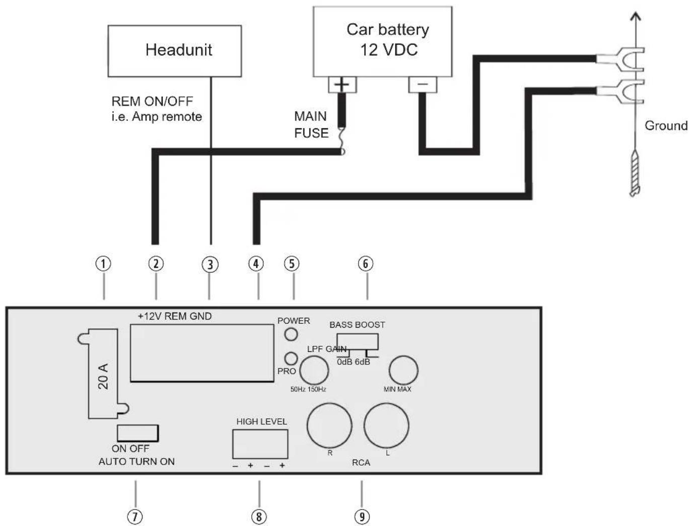
The amplifier is turned on by applying +12V to the remote turn-on terminal (REM). The wire lead to this terminal should be connected to the „Amp remote“ lead from the car stereo which will provide the +12V only when the car stereo is turned on.
INPUT CONNECTIONS
This amplifier features both high level and low-level (RCA) input capability. Use either the low-level or high-level inputs, not both. If the car stereo does not provide low-level outputs, the amplifier may be connected via the speaker (high-level) outputs from the car stereo. Wire the speaker leads from the car stereo to the 4-pin adaptor harness as shown in the diagram (shielded cables are not required for this application) and plug the connector into the high input connector on the amplifier.


Note:
When using the high-level input of your OE factory radiothat features no dedicated REM signal, select "Auto turn-on" ON.
flowchart
graph TD
    A["Headunit"] -->|REM ON/OFF i.e. Amp remote| B["Car battery 12 VDC"]
    B --> C["Ground"]
    D["+12V REM GND"] --> E["POWER"]
    D --> F["BASS BOOST"]
    E --> G["PRO"]
    F --> H["LPF GAIN 0dB 6dB"]
    F --> I["MIN MAX"]
    J["ON OFF AUTO TURN ON"] --> K["HIGH LEVEL"]
    K --> L["R"]
    K --> M["L"]
    N["Ground"] --> O["Ground"]
① Fuse (20A)
② +12V Power Terminal
③ REM (Amp Remote) Terminal
④ GND Power Terminal
⑤ Power/Protect Status LED
⑥ Switchable Bass-Boost 0 – 6 dB
⑦ Auto Turn-On/Off for High Level Input
⑧ High Level Input
⑨ RCA Input

natural_image
Two identical line drawings of a vertical rod with a dotted line above, no text or symbols present.R+L from Low Level Audio Out of the headunit.
Use a Y Adapter if you want to directly connect to a mono subwoofer output.

Use the specified amperage fuse only.
Higher amperage may cause serious damage or even a fire.
ADJUSTMENTS
Turn-on your head-unit keeping your volume at the lowest setting. The green status LED on the front of the AXB20STP amp-module should light up now. If not, turn-off your head-unit and re-check all wiring to and from the amplifier for missing or faulty connections.
PROTECTION INDICATOR
This active subwoofer is equipped with an overload protection. In case of internal short circuit or increased temperature, the overload protection is activated, and the red LED indicator comes on. Through this the amplifier is protected against damage. In case of the thermal protection a certain cooling time must be allowed after which the amp-module will resume operation.
LOWPASS CROSSOVER FREQUENCY ADJUSTMENT
The lowpass cut-off frequency setting, marked as „LPF“ on the active subwoofer, depends on the dimension of the vehicle and the mounting location. As a rule of thumb, settings in a range between 80 to 100 Hz will render best sonic results. For an intermediate lowpass crossover setting to attempt input gain and phase-shift control adjustments, go for a VR-pot set to approx. 80 Hz – and after input gain has been adjusted, it is advisable to fine tune the lowpass crossover frequency for best possible sound quality.
Note: In general, setting the lowpass crossover frequency too low, will result in a weak and muddy sounding bass, while setting this crossover frequency too high will result in a 'booming' bass sound and reduced low end extension.
INPUT GAIN
The input level control allows the AXB20STP to be matched to almost any car, to work well within a wide range of output levels. The following procedure can be applied: Turn on the head unit and adjust the volume level to an elevated but still sane output. Now using a screwdriver, increase the GAIN potentiometer by turning it clockwise (on the AXB20STP side panel) until the bass content is perceived as sufficient and balanced.
BASS BOOST
The bass boost slide switch with positions „0 dB“ or “6dB” has to be played by ear. With the slide switch set to “0 dB”, the bass boost is deactivated, with position “6 dB”, the frequencies around 40 Hz are boosted – which will improve the low end extension in smaller compact type cars. Note that with bass boost enabled, the subwoofer will have less max. dB headroom since the very low frequencies are amplified with a higher gain and thus, woofer and amp module reach their respective limits earlier.
Sehr geehrter Kunde
natural_image
Two identical wire connectors with dotted vertical lines above them, no text or symbols presentAXTON warrants this active subwoofer to be free of defects in materials and workmanship for two years from the date of purchase at retail, contingent upon being properly installed and approved by an authorized AXTON dealer, granted to the original purchaser. AXTON Inc. will at its own discretion, repair or replace defective units during the warranty period.
Should your AXTON product require warranty service, please return it to the retailer from whom it was purchased. Please do not send any product to AXTON. Should you have difficulty in finding an authorized AXTON service center, details are available national distributor in the country of purchase.
Abuse of this actice subwoofer due to excessive amplifier power, improper installation modification, or physical damage is not covered under warranty.
State: ZIP or Postal Code:
Country:
Your Dealer:






- UNPACKING THE SYSTEM
- SPECIFICATIONS
- Add a main fuse holder with appropriate fuse volume to the (+) power cable in a distance of not more than 30 cm from the positive battery pole.
- IMPORTANT:
- GROUND CONNECTION
- REMOTE TURN-ON CONNECTION
- INPUT CONNECTIONS
- Note:
- ADJUSTMENTS
- PROTECTION INDICATOR
- LOWPASS CROSSOVER FREQUENCY ADJUSTMENT
- INPUT GAIN
- BASS BOOST
- Sehr geehrter Kunde
Brand : Axton
Model : ATB20STP
Category : Subwoofer