
PSVH 56 A1 - Power tools PARKSIDE - Free user manual and instructions
Find the device manual for free PSVH 56 A1 PARKSIDE in PDF.


| Product Type | Wet and Dry Vacuum Cleaner |
| Brand | Parkside |
| Model | PSVH 56 A1 |
| Tank Capacity | 56 liters |
| Power Supply | 220-240 V ~ 50/60 Hz |
| Power Consumption | 1200 W |
| Dimensions (approx.) | 40 x 40 x 55 cm |
| Weight (approx.) | 7.5 kg |
| Suction Hose Length | 2.5 m |
| Nozzles Included | Floor nozzle, crevice nozzle, utility nozzle |
| Filter Type | Cartridge filter (washable) |
| Blower Function | Yes |
| Protection Class | II |
| Sound Level | 75 dB(A) |
| Maintenance | Clean filter after each use; empty tank regularly; check hose for blockages |
| Safety Features | Overload protection, safety float valve (for wet vacuuming) |
| Spare Parts Availability | Filters, hoses, nozzles available from Parkside service or online |
| General Information | Suitable for dry and wet vacuuming; compact design with wheels for mobility |
Frequently Asked Questions - PSVH 56 A1 PARKSIDE
User questions about PSVH 56 A1 PARKSIDE
0 question about this device. Answer the ones you know or ask your own.
Ask a new question about this device
Download the instructions for your Power tools in PDF format for free! Find your manual PSVH 56 A1 - PARKSIDE and take your electronic device back in hand. On this page are published all the documents necessary for the use of your device. PSVH 56 A1 by PARKSIDE.
USER MANUAL PSVH 56 A1 PARKSIDE
natural_image
Open mechanical tool kit with visible internal compartments and external tools (no text or symbols)SET PARA ATORNILLADO OCULTO EN MADERA / SET VITI A SCOMPARSA PSVH 56 A1
ES
SET PARA ATORNILLADO OCULTO EN MADERA
Operating instructions
IT MT
SET VITI A SCOMPARSA
ES
Before reading, unfold the page containing the illustrations and familiarise yourself with all functions of the device.
DE AT CH
GB/MT Operating instructions Page 21
natural_image
Illustration of a hand using a measuring tool to cut a wooden block, no text or symbols present
natural_image
Line drawing of a hand holding a device with an arrow indicating direction (no text or symbols)

natural_image
Technical illustration of a mechanical tool interacting with a drill bit, showing motion direction (no text or symbols)
natural_image
Technical line drawing of a mechanical clamp or measuring device mounted on a wooden base (no text or symbols)
natural_image
Two-panel diagram showing a wooden cabinet with two hanging clips and a base, no text or symbols present.
natural_image
Technical illustration of a mechanical clamp or bracket assembly with a close-up view of a wooden panel corner (no text or symbols)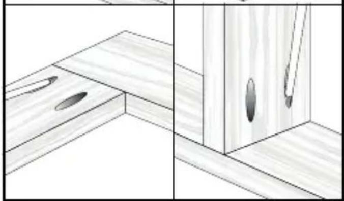
natural_image
Architectural line drawing of a wooden cabinet with two ovals and a door, showing front and side views (no text or symbols)
natural_image
Illustration of hands holding a mechanical component with an arrow indicating direction (no text or symbols)
natural_image
Technical line drawing of a wooden cabinet lock assembly (no text or symbols)
Índice
Introducción 2
natural_image
Four different screwdriver illustrations arranged horizontally, no text or symbols present

natural_image
Three simple line drawings: a circular ring, a L-shaped bracket, and a numbered circle (no text or symbols)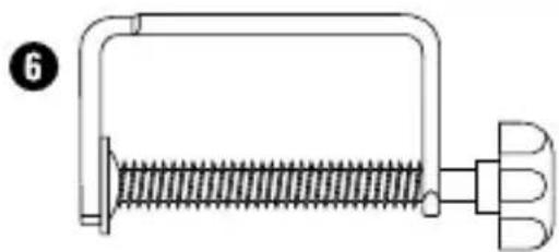
natural_image
Pure mechanical diagram of a spring-loaded clamp or bracket with no text or symbols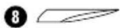
INDICACIÓN
KOMPERNASS HANDELS GMBH
BURGSTRASSE 21
44867 BOCHUM
ALEMANIA
www.kompernass.com
Indice
Introduzione 12
NOTA
KOMPERNASS HANDELS GMBH
BURGSTRASSE 21
44867 BOCHUM
GERMANIA
www.kompernass.com
Contents
Introduction 22
Information about these operating instructions ..... 2 2
Intended use 22
Safety 22
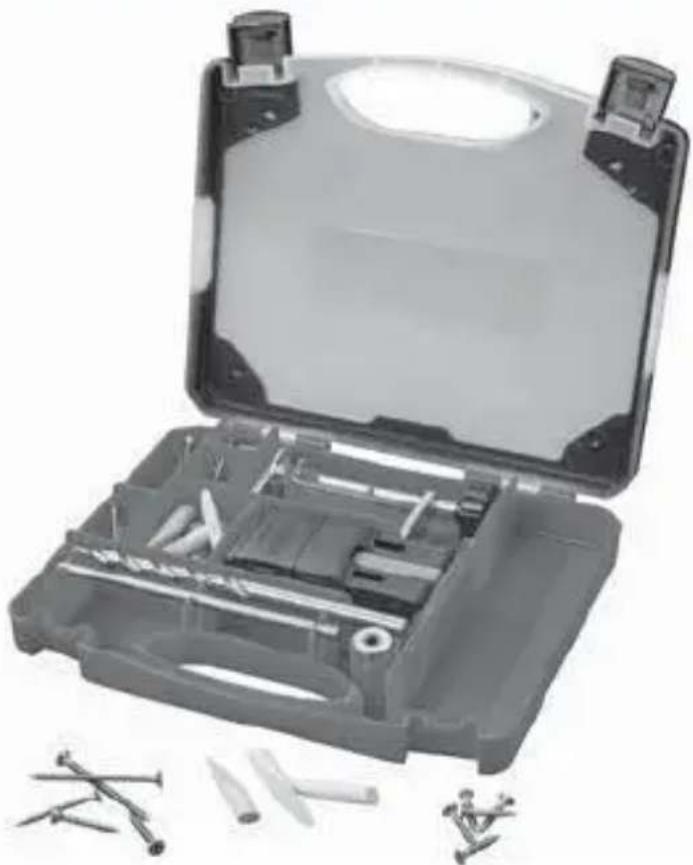
Package contents 24
Use 25
Measuring wood thickness (Fig. A) 25
Setting the wood thickness (Fig. B) 25
Setting the drilling depth (Fig. C) 26
Drilling holes (Fig. D) 26
Making corner, surface and T-shaped joints (Fig. E) ..... 27
Making mitred joints (Fig. F) 27
Working on pre-assembled wooden workpieces (Fig. G) ..... 2 8
Cleaning.... 28
Storage 29
Disposal 29
Service 30
Importer 30
Introduction
Information about these operating instructions

Congratulations!
You have purchased a high-quality product. Familiarise yourself with the product before using it for the first time. To do this, read the following operating instructions thoroughly. Use the product only as described and for the range of applications specified. Keep these operating instructions in a safe place. Please also pass these operating instructions on to any future owner(s).
Intended use
This product is exclusively intended to produce concealed screw joints in wood. You can use the product to create corner joints, surface joints, T-shaped joints and mitred joints. The product is also suitable for already assembled wooden workpieces. Commercial or industrial use is not permitted. No liability will be assumed in cases of improper use. No liability will be assumed for damage caused by misuse or improper handling, the use of force or unauthorised modification. The risk is borne solely by the user.
Safety
- Check the product before every use to make sure it is in perfect condition. Do not use the product if it is damaged in any way.
- Do not allow children to use the product unless they are being supervised. Children are not always able to correctly recognise potential dangers. This product is not a toy.
This product is not intended for use by individuals (including children) with reduced physical, sensory, or mental capabilities. It may also not be used by individuals who lack experience and/or knowledge unless they are supervised by a person responsible for their safety or have received instructions on how to use the product from such a person.
■ Some of the supplied parts can be swallowed. If a part is swallowed, seek medical advice as soon as possible.
Use protective equipment. For your own safety, always wear ear muffs, a breathing mask/dust mask and safety goggles.
Please observe the operating instructions for the drill/the cordless screwdriver when using the product.
■ Unplug the appliance before fitting or changing parts.
■ All parts must be properly fitted before use otherwise there is a risk of serious injury!
■ Only operate the drill/the cordless screwdriver in clockwise mode. The hammer function must be switched off.
■ Never remove the fitted protective devices.
■ Firmly clamp the wooden workpiece you are working on.
■ Ensure that you are standing firmly and the wooden workpiece is stable.
■ Rust discoloration or other signs of chemical or mechanical change to the parts can cause premature failure of the parts.
Package contents
1 × drilling jig
2 1 × HSS step drill ∅ 9.5 mm (length: 180 mm)
③ 1 × depth stop ∅ 9.5 mm
4 1 × hex key SW 3
5 1 × bit attachment (length: 150 mm)
6 1 × clamp
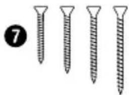
7 40 × woodscrews:
10 × woodscrews ∅ 4 mm × 25 mm
10 × woodscrews ∅ 4 mm × 30 mm
10 × woodscrews ∅ 4 mm × 40 mm
10 × woodscrews ∅ 4 mm × 60 mm
8 10 × screw head covers (dried beechwood)
These operating instructions


natural_image
Four different screwdriver illustrations arranged horizontally, no text or symbols present

natural_image
Three simple line drawings: a circular ring, a L-shaped bracket, and a numbered circle (no text or symbols)
natural_image
Pure mechanical diagram of a spring-loaded clamp or bracket with no text or symbols
NOTE
▶ Check the package for completeness and signs of visible damage.
Use
NOTE
In addition to the items supplied, you will require a drill or a cordless screwdriver and an additional clamp in order to use the product.
Measuring wood thickness (Fig. A)
◆ Press the limit stop on the drilling jig1 downwards.
Place the drilling jig 1 against the wooden workpiece and read off the wood thickness.
Setting the wood thickness (Fig. B)
- Set the measured wood thickness on the drilling jig using the following table.
| Wood thickness Setting | |
| 12-18 mm 12 | |
| 19-26 mm 19 | |
| 27-37 mm 27 | |
| ≥38 mm 38 |
◆ Hold down the knob and push the drilling jig until the required setting is reached.
◆ Release the knob once the drilling jig is engaged.
Setting the drilling depth (Fig. C)
◆ Push the drilling jig ① limit stop upwards and place the drilling jig ① on a flat surface.
Place the step drill ^2 right up against the side of the drilling jig with the step drill symbol. The tip of the step drill should contact the tip of the step drill symbol.
♦ Push the depth stop 3 onto the step drill 2 is far as the edge of the drilling jig 1
♦ Screw the depth stop ③ tight using the hex key ④.
Drilling holes (Fig. D)
NOTE
To provide a stable hold, drill two woodscrew into each joint.
◆ Clamp the step drill ^2 (with the depth stop 3 screwed on) into a drill or a cordless screwdriver.
◆ Press the limit stop on the drilling jig downwards.
◆ Place the limit stop on the drilling jig1 against the wooden workpiece.
♦ Fix the drilling jig ^1 and the wooden workpiece firmly in place with the clamp ^6
Drill into the wooden workpiece as far as the depth stop ③.
Making corner, surface and T-shaped joints (Fig. E)
When making the joints shown, fix the wooden workpiece in place with a clamp (not included in delivery).
NOTE
▶ Ensure that you clamp the wooden workpiece precisely and tightly.
Select the appropriate woodscrew ^7 with the help of the following table.
Wood thickness Woodscrew size
| ≥ 12 mm ∅ 4 mm × 25 mm |
| ≥ 19 mm ∅ 4 mm × 30 mm |
| ≥ 27 mm ∅ 4 mm × 40 mm |
| ≥ 38 mm ∅ 4 mm × 60 mm |
♦ Screw in the selected woodscrew 7 using the bit attachment 5
Making mitred joints (Fig. F)
◆ Proceed as described for the previous joints (see Figs. A–C). Measure the wood thickness and set the drilling depth.
Place the drilling jig ^1 as shown in the illustration.
Drill holes as described in the section "Drilling holes (Fig. D)".
Connect the wooden workpieces as described in the section "Making corner, surface and T-shaped joints (Fig. E)".
Working on pre-assembled wooden workpieces (Fig. G)
◆ Set the drilling depth (see figures A to C).
♦ Push the limit stop on the drilling jig1 upwards.
◆ Fix the drilling jig ^1 and the wooden workpiece firmly in place with the clamp ^6
Select the appropriate woodscrew with the help of the table.
NOTE
The woodscrew ^7 selected must be 5 mm longer since the width of the inserted limit stop (5 mm) must be added to the length.
♦ Screw the selected woodscrew ^7 in using the bit attachment ^5 after drilling.
◆ Fill the drill holes with glue and push the screw head covers ⑧ into the holes.
Cleaning

WARNING
Before cleaning, always remove the step drill ② or the bit attachment ⑤ from the drill or cordless screwdriver.
▶ Do not use aggressive or abrasive cleaning agents, as these can damage the surfaces of the product.
◆ Use a soft, dry brush to remove drilling dust from the product.
You can also clean the product using a dry cloth.
Storage
All parts must be stored in the container in which they were delivered to protect them from external factors.
Disposal

Dispose of the product via an approved waste disposal company or your municipal waste disposal facility. Comply with all applicable regulations. In case of doubt, contact your disposal facility.

Your local community or municipal authorities can provide information on how to dispose of the worn-out product.

Dispose of the packaging in an environmentally friendly manner. Note the labelling on the packaging and separate the packaging material components for disposal if necessary. The packaging material is labelled with abbreviations (a) and numbers (b) with the following meanings:
1-7:plastics,
20-22: paper and cardboard,
80-98: composites.
Service

Service Great Britain
Tel.: 0800 404 7657
E-Mail: kompernass@lidl.co.uk

Service Malta
Tel.: 80062230
E-Mail: kompernass@lidl.com.mt
IAN 337010_2001
Importer
Please note that the following address is not the service address. Please use the service address provided in the operating instructions.
KOMPERNASS HANDELS GMBH
BURGSTRASSE 21
44867 BOCHUM
GERMANY
www.kompernass.com
Inhaltsverzeichnis
Einführung 32

HINWEIS
KOMPERNASS HANDELS GMBH
BURGSTRASSE 21
44867 BOCHUM
DEUTSCHLAND
www.kompernass.com
KOMPERNASS HANDELS GMBH
BURGSTRASSE 21
44867 BOCHUM
GERMANY
www.kompernass.com
- SET PARA ATORNILLADO OCULTO EN MADERA / SET VITI A SCOMPARSA PSVH 56 A1
- SET PARA ATORNILLADO OCULTO EN MADERA
- SET VITI A SCOMPARSA
- ES
- DE AT CH
- Índice
- Introducción 2
- INDICACIÓN
- Indice
- Introduzione 12
- NOTA
- Contents
- Introduction 22
- Safety 22
- Package contents 24
- Use 25
- Cleaning.... 28
- Storage 29
- Disposal 29
- Service 30
- Importer 30
- Introduction
- Information about these operating instructions
- Intended use
- Safety
- Package contents
- NOTE
- Use
- Measuring wood thickness (Fig. A)
- Setting the wood thickness (Fig. B)
- Setting the drilling depth (Fig. C)
- Drilling holes (Fig. D)
- Making corner, surface and T-shaped joints (Fig. E)
- Making mitred joints (Fig. F)
- Working on pre-assembled wooden workpieces (Fig. G)
- Cleaning
- WARNING
- Storage
- Disposal
- Service
- Importer
- Inhaltsverzeichnis
- Einführung 32
- HINWEIS
- KOMPERNASS HANDELS GMBH
Brand : PARKSIDE
Model : PSVH 56 A1
Category : Power tools