
CI 8-150 DSP - Receiver NAD - Free user manual and instructions
Find the device manual for free CI 8-150 DSP NAD in PDF.


| Type | 8-Channel Amplifier Receiver |
| Brand | NAD |
| Model | CI 8-150 DSP |
| Continuous Output Power (8 ohms, all channels driven) | >150 W |
| Continuous Output Power (8 ohms, two channels driven) | >180 W |
| Continuous Output Power (4 ohms, all channels driven) | >180 W |
| Continuous Output Power (4 ohms, two channels driven) | >300 W |
| Bridge Mode Power (8 ohms, all channels driven) | >280 W |
| Bridge Mode Power (8 ohms, two channels driven) | >500 W |
| Total Harmonic Distortion (THD) | <0.02% (20 Hz - 20 kHz, 1 W to 120 W) |
| Signal-to-Noise Ratio | >90 dB (A-weighted, ref. 1 W out, 8 ohms) |
| Frequency Response | ±0.5 dB (20 Hz - 20 kHz) |
| Damping Factor | >150 (ref. 8 ohms, 20 Hz - 6.5 kHz) |
| Input Sensitivity (for 150 W, 8 ohms) | 1450 mV |
| Number of Channels | 8 |
| Digital Audio Inputs | 2 Optical, 2 Coaxial |
| Analog Audio Inputs | 8 RCA Line Inputs, 2 Global (A/B) RCA |
| Speaker Outputs | 8 via Terminal Blocks (supplied) |
| Power Consumption (Standby) | 0.5 W (Eco Mode), 1.2 W (Network Standby) |
| Dimensions (W x H x D) | 483 x 90 x 435 mm (19 x 3.5 x 17.1 inches) |
| Weight (Shipping) | 17.6 kg (38.8 lbs) |
| Power Modes | Power Button, Always On, 12V Trigger, Signal Sense |
| Protection Features | Amplifier Protection (short circuit), DC Protection, Overvoltage/Undervoltage, Over Temperature |
| DSP Features | Parametric EQ with Slope, Q, Frequency, Gain; 9 Presets; Test Signal (Pink Noise or Line Input) |
| Control & Connectivity | Web-based UI, LAN, IR In/Out, 12V Trigger In, Bridge Mode |
| Cooling | Two variable-speed fans (left and right) |
Frequently Asked Questions - CI 8-150 DSP NAD
User questions about CI 8-150 DSP NAD
0 question about this device. Answer the ones you know or ask your own.
Ask a new question about this device
Download the instructions for your Receiver in PDF format for free! Find your manual CI 8-150 DSP - NAD and take your electronic device back in hand. On this page are published all the documents necessary for the use of your device. CI 8-150 DSP by NAD.
USER MANUAL CI 8-150 DSP NAD
Owner's Manual
- Read instructions – All the safety and operating instructions should be read before the product is operated.
- Retain instructions - The safety and operating instructions should be retained for future reference.
- Heed Warnings - All warnings on the product and in the operating instructions should be adhered to.
- Follow Instructions - All operating and use instructions should be followed.
- Cleaning - Unplug this product from the wall outlet before cleaning. Do not use liquid cleaners or aerosol cleaners. Use a dry cloth for cleaning.
- Attachments - Do not use attachments not recommended by the product manufacturer as they may cause hazards.
- Water and Moisture - Do not use this product near water-for example, near a bath tub, wash bowl, kitchen sink, or laundry tub; in a wet basement; or near a swimming pool; and the like.
- Accessories - Do not place this product on an unstable cart, stand, tripod, bracket, or table. The product may fell, causing serious injury to a child or adult and serious damage to the product. Use only with a cart, stand, tripod, bracket, or table recommended by the manufacturer, or sold with the product. Any mounting of the product should follow the manufacturer's instructions, and should use a mounting accessory recommended by the manufacturer.
- Cart product and cart combination should be moved with care. Quick stops, excessive force, and uneven surfaces may cause the product and cart combination to overturn.
- Ventilation - Slots and openings in the cabinet are provided for ventilation to ensure reliable operation of the product and to protect it from overheating. These openings must not be blocked or covered. The openings should never be blocked by placing the product on a bed, sofa, rug, or other similar surface. This product should not be placed in a built-in installation such as a bookcase or rack unless proper ventilation is provided or the manufacturer's instructions have been adhered to.
- Power Sources - This product should be operated only from the type of power source indicated on the marking label and connected to a MAINS socket outlet with a protective earthing connection. If you are not sure of the type of power supply to your home, consult your product dealer or local power company.
- Power-Cord Protection - Power-supply cords should be routed so that they are not likely to be walked on or pinched by items placed upon or against them, paying particular attention to cords at plugs, convenience receptacles, and the point where they exit from the product.
- Mains Plug - Where the mains plug or an appliance coupler is used as the disconnect device, the disconnect device shall remain readily operable.
- Outdoor Antenna Grounding - If an outside antenna or cable system is connected to the product, be sure the antenna or cable system is grounded so as to provide some protection against voltage surges and built-up static charges. Article 810 of the National Electrical Code, ANSI/NFPA 70, provides information with regard to proper grounding of the mast and supporting structure, grounding of the lead-in wire to an antenna discharge unit, size of grounding conductors, location of antenna discharge unit, connection to grounding electrodes, and requirements for the grounding electrode.
- Lightning - For added protection for this product during a lightning storm, or when it is left unattended and unused for long periods of time, unplug it from the wall outlet and disconnect the antenna or cable system. This will prevent damage to the product due to lightning and power-line surges.
- Power Lines - An outside antenna system should not be located in the vicinity of overhead power lines or other electric light or power circuits, or where it can fall into such power lines or circuits. When installing an outside antenna system, extreme care should be taken to keep from touching such power lines or circuits as contact with them might be fatal.
• Overloading - Do not overload wall outlets, extension cords, or integral convenience receptacles as this can result in a risk of fire or electric shock. - Flame Sources - No naked flame sources, such as lighted candles, should be placed on the product.
- Object and Liquid Entry - Never push objects of any kind into this product through openings as they may touch dangerous voltage points or short-out parts that could result in a fire or electric shock. Never spill liquid of any kind on the product.
-
Headphones - Excessive sound pressure form earphones and headphones can cause hearing loss.
-
Damage Requiring Service - Unplug this product from the wall outlet and refer servicing to qualified service personnel under the following conditions:
- When the power-supply cord or plug is damaged.
- If liquid has been spilled, or objects have fallen into the product.
- If the product has been exposed to rain or water.
- If the product does not operate normally by following the operating instructions. Adjust only those controls that are covered by the operating instructions as an improper adjustment of other controls may result in damage and will often require extensive work by a qualified technician to restore the product to its normal operation.
- If the product has been dropped or damaged in any way.
- When the product exhibits a distinct change in performance—this indicates a need for service.
- Replacement Parts - When replacement parts are required, be sure the service technician has used replacement parts specified by the manufacturer or have the same characteristics as the original part. Unauthorized substitutions may result in fire, electric shock, or other hazards.
- Battery Disposal - When disposing of used batteries, please comply with governmental regulations or environmental public instruction's rules that apply in your country or area.
- Safety Check - Upon completion of any service or repairs to this product, ask the service technician to perform safety checks to determine that the product is in proper operating condition.
WARNING
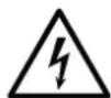
THE LIGHTNING FLASH WITH I ARROWLED SYMBOL, WITH IN AN EQUILATERAL TRIANGLE, IS INTENDED TO ALERT THE USER TO THE PRESENCE OF UNINSULATED "DANGEROUS VOLTAGE" WITH IN THE PRODUCT'S ENCLOSURE THAT MAY BE OF SUFFICIENT MAGNITUDE TO CONSTITUTE A RISK OF ELECTRIC SHOCK TO PERSONS

THE EXCLAMATION POINT WITHIN AN EQUILATERAL TRIANGLE IS INTENDED TO ALERT THE USER TO THE PRESENCE OF IMPORTANT OPERATING AND MAINTENANCE (SERVICING) INSTRUCTIONS IN THE LITERATURE ACCOMPANYING THE APPLIANCE.
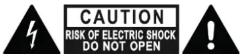
WARNING : SHOCK HAZARD - DO NOT OPEN ATTENTION : RISQUE DE CHOC ELECTRIQUE-NE PAS OUVRIR
CAUTION REGARDING PLACEMENT
To maintain proper ventilation, be sure to leave a space around the unit (from the largest outer dimensions including projections) than is equal to, or greater than shown below. Left and Right Panels: 10 cm
Rear Panel: 10 cm
Top Panel: 10 cm
Do not install near any heat sources such as radiators, heat registers, stoves, or other apparatus (including amplifiers) that produce heat.
Do not defeat the safety purpose of the polarized or grounding - type plug. A polarized plug has two blades with one wider than the other. A grounding type plug has two blades and a third grounding prong. The wide blade or the third prong is provided for your safety. When the provided plug does not fit into your outlet, consult an electrician for replacement of the obsolete outlet.
The apparatus should only be used in moderate climates.
FCC STATEMENT
This equipment has been tested and found to comply with the limits for Class B digital device, pursuant to Part. 15 of the FCC Rules. These limits are designed to provide reasonable protection against harmful interference in a residential installation. This equipment generates, uses, and can radiate radio frequency energy and, if not installed and used in accordance with the instructions, may cause harmful interference to radio communications. However, there is no guarantee that interference will not occur in a particular installation. If this equipment does cause harmful interference to radio or television reception, which can be determined by turning the equipment off and on, the user is encouraged to try to correct the interference by one or more of the following measures:
• Reorient or relocate the receiving antenna.
- Increase the separation between the equipment and receiver.
- Connect the equipment into an outlet on a circuit different from that to which the receiver is connected.
- Consult the dealer or an experienced radio TV technician for help.
CAUTION
- Changes or modifications to this equipment not expressly approved by NAD Electronics for compliance could void the user's authority to operate this equipment.
• To prevent electric shock, match wide blade of plug to wide slot, fully insert. - Marking and rating plate can be found at the rear panel of the apparatus.
- To reduce the risk of fire or electric shock, do not expose this apparatus to rain or moisture. The apparatus shall not be exposed to dripping or splashing and that no objects filled with liquids, such as vases, shall be placed on apparatus.
- Mains plug is used as disconnect device and it should remain readily operable during intended use. In order to disconnect the apparatus from the mains completely, the mains plug should be disconnected from the mains socket outlet completely.
- An appliance with a protective earth terminal should be connected to a mains outlet with a protective earth connection.
RESPONSIBLE PARTY
Lenbrook International
633 Granite Court
Pickering, ON L1W 3K1
Canada
Tel:19058316555
IF IN DOUBT CONSULT A COMPETENT ELECTRICIAN.

This product is manufactured to comply with the radio interference requirements of EEC DIRECTIVE 2004/108/EC.
NOTES ON ENVIRONMENTAL PROTECTION

At the end of its useful life, this product must not be disposed of with regular household waste but must be returned to a collection point for the recycling of electrical and electronic equipment. The symbol on the product, user's manual and packaging point this out.
The materials can be reused in accordance with their markings. Through reuse, recycling of raw materials, or other forms of recycling of old products, you are making an important contribution to the protection of our environment.
Your local administrative office can advise you of the responsible waste disposal point.
INFORMATION ABOUT COLLECTION AND DISPOSAL OF WASTE BATTERIES (DIRECTIVE 2006/66/EC OF THE EUROPEAN PARLIAMENT AND THE COUNCIL OF EUROPEAN UNION) (FOR EUROPEAN CUSTOMERS ONLY)
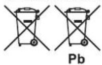
Batteries bearing any of these symbols indicate that they should be treated as "separate collection" and not as municipal waste. It is encouraged that necessary measures are implemented to maximize the separate collection of waste batteries and to minimize the disposal of batteries as mixed municipal waste.
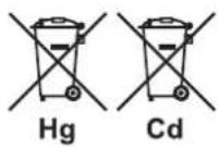
End-users are exhorted not to dispose waste batteries as unsorted municipal waste. In order to achieve a high level of recycling waste batteries, discard waste batteries separately and properly through an accessible collection
point in your vicinity. For more information about collection and recycling of waste batteries, please contact your local municipality, your waste disposal service or the point of sale where you purchased the items.
By ensuring compliance and conformance to proper disposal of waste batteries, potential hazardous effects on human health is prevented and the negative impact of batteries and waste batteries on the environment is minimized, thus contributing to the protection, preservation and quality improvement of the environment.
WHAT'S IN THE BOX
Packed with your CI 8-150 you will find
- Two detachable mains power cord
• 4 pieces of 4-position terminal block (for SPEAKERS)
• 1 piece of 4-position terminal block (for IR IN/OUT) - 1 piece of 2-position terminal block (for +12V TRIGGER IN)
• 4 pieces of feet with mounting screws - Quick Setup Guide
QUICK START
Refer to the supplied CI 8-150 Quick Setup Guide for basic instructions in setting up your new NAD CI 8-150. The following important notes must also be observed when setting up your CI 8-150.
IMPORTANT SETUP NOTES
- Before setting up or making connections, ensure that the CI 8-150 and other devices to be connected to CI 8-150 are unplugged or powered down.
- Connect external speaker cables to supplied SPEAKERS terminal block ensuring that the connections match CI 8-150's rear panel SPEAKERS terminal markings.
- Bare wire or loose strands from the speaker cables must not touch the rear panel or other speaker terminals.
- After installing the external speaker cables to the supplied SPEAKER terminal blocks, plug in the wired up SPEAKER terminal blocks to corresponding SPEAKERS (1-8) rear panel terminals of CI 8-150.
- Connect corresponding end of the AC power cord to CI 8-150's AC mains input and the AC power cord's plug connected to mains power outlet.
- Press front panel POWER button to switch ON CI 8-150 from standby mode. Line input channels with active input signal will have their corresponding front panel LED indicators illuminated blue.
SAVE THE PACKAGING
Please save the box and all of the packaging in which your CI 8-150 arrived. Should you move or otherwise need to transport your CI 8-150, this is by far the safest container to do so. We've seen too many otherwise perfect components damaged in transit for lack of a proper shipping carton, so please: Save that box
ATTENTION!
Please ensure that the CI 8-150 is powered off or unplugged from the mains power outlet before making any connections. It is also advisable to power down or unplug all associated components while making or breaking any signal or AC power connections.
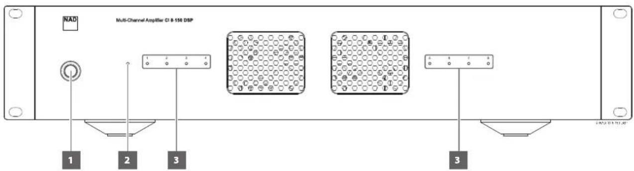
1 POWER BUTTON
- Press this button to switch ON CI 8-150 from standby mode. All eight LINE INPUT LED indicators will turn red for about 10 seconds, briefly all blue and then blue for those LINE INPUT channels with active line input signal or no light (except Standby LED) in the absence of any active line input signal. The 10 seconds delay in powering up is intended for system power stability and security self-check.
- Pressing the Power button again turns the unit back to standby mode. The Standby LED indicator will turn from blue to amber.
NOTE
"Power Mode" (Settings - Power Settings - Power Mode) must be set to "Power Button" for the unit to power up via front panel Power button.
2 STANDBY LED
- This indicator will light up amber when CI 8-150 is at standby mode. When CI 8-150 is powered up from standby mode, this indicator will illuminate blue.
STANDBY AND LINE INPUT LED STATUS INDICATORS
| DESCRIPTION STANDBY LED STATUS LINE INPUT LED 1-8 STATUS | ||
| Operating mode Blue | Corresponding Line Input LED indicator is solid blue with active line input signal or no light in the absence of any active line input signal. | |
| Standby mode Amber Off, no light | ||
| System reboot Flashing amber Red → Blue → Off, no light | ||
| Overvoltage or under voltage | Red Off, no light | |
| AMP current error Blue | Corresponding channel LED is red. | |
| AMP DC error Red Off, No light | ||
3 LINE INPUT (1 - 8) LED INDICATORS
• LINE INPUT channels with active input signal will have their corresponding front panel LINE INPUT LED indicators illuminated in blue.
- If there is no active input signal connected to a particular LINE INPUT, the corresponding front panel LINE INPUT LED indicator will not light up.
IMPORTANT NOTICE
If the selected source is GLOBAL A and/or GLOBAL B and there is an active input signal at either GLOBAL input terminal, all eight LINE INPUT LED indicators will illuminate at the same time.
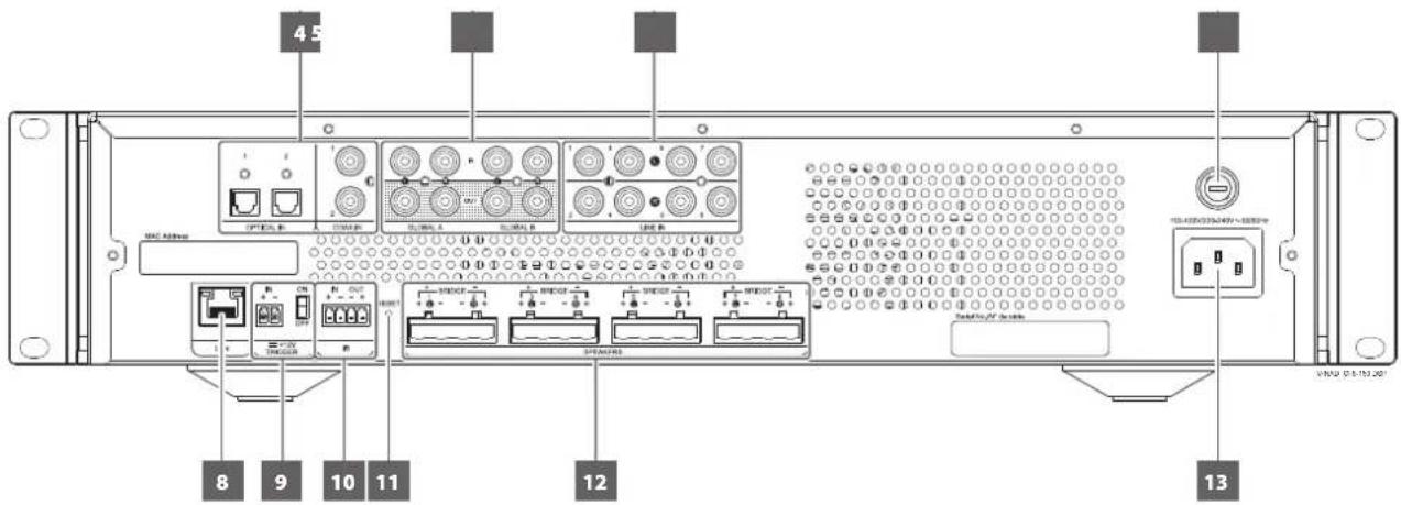
4 OPTICAL IN 1-2/COAXIAL IN 1-2
- Use applicable connectors (not supplied) to connect OPTICAL IN 1-2 and/or COAXIAL IN 1-2 terminals to corresponding Digital Audio Output terminals of compatible external devices such as preamplifiers, processors or other applicable devices.
- Configure LINE INPUT 1-8 via INPUT/OUTPUT menu of the web-based CI 8-150 User Interface. OPTICAL IN 1-2 and/or COAXIAL IN 1-2 sources can be assigned to a specific or multiple speaker OUTPUT channel(s).
5 GLOBAL A, GLOBAL B IN/OUT
- These IN/OUT terminals are dedicated only to GLOBAL settings.
- Configure GLOBAL A/GLOBAL B via the INPUT/OUTPUT menu of the web-based CI 8-150 User Interface.
GLOBAL A IN, GLOBAL B IN
- Use RCA-to-RCA leads to connect Audio Output terminals from compatible external devices such as preamplifiers, processors or other applicable devices to GLOBAL A IN and/or GLOBAL B IN terminals.
- If GLOBAL A and/or GLOBAL B are turned ON in the web-based CI 8-150 User Interface, the source(s) connected to GLOBAL IN terminals will become the active input defeating all other active line input channels.
• GLOBAL A takes priority over GLOBAL B.
GLOBAL A OUT, GLOBAL B OUT
- Use RCA-to-RCA leads to connect GLOBAL A and/or GLOBAL B OUT terminals to audio INPUT terminals of compatible external devices such as amplifiers, receivers or other applicable devices.
- The GLOBAL OUT terminals are line level "loop through" output. The same level of input signal from corresponding GLOBAL IN is available at the corresponding GLOBAL OUT terminal thereby allowing the same signal to be shared or passed on to another amplifier.
- At standby mode, line level "loop through" output at GLOBAL A OUT and GLOBAL B OUT terminals remain available as long as the sources for GLOBAL A IN and GLOBAL B IN are active.
6 LINE INPUT (1-8)
- Use RCA-to-RCA leads to connect the LINE INPUT terminals to corresponding Audio Output terminals of compatible external devices such as preamplifiers, processors or other applicable devices.
- Configure LINE INPUT 1-8 via INPUT/OUTPUT menu of the web-based CI 8-150 User Interface. Each LINE INPUT source can be assigned to a specific or multiple speaker OUTPUT channel(s).
- The LINE INPUT ports are numbered 1 to 8. LINE INPUT channels with active input signal will have their corresponding front panel LINE INPUT LED indicators illuminated in blue. If there is no active input signal connected to a particular LINE INPUT, the corresponding front panel LINE INPUT LED indicator will not light up.
7 FUSE HOLDER
- In the unlikely event a fuse needs to be replaced, unplug the AC power cord from the mains power outlet. Then, remove all connections from the amplifier. Use a flathead screwdriver or similar to open the fuse holder via the slot located at the top edge of the fuse holder. With the screwdriver in place, push it outward to unlatch and open the fuse holder.
- Only replace the fuse with the same type, size, and specification – T15AL 250V.
IMPORTANT NOTICE
Do not use any substitute fuse of different type, rating or value. Failure to observe this precaution may cause damage to the amplifier circuits and may create a fire hazard and/or defeat the safety built into the amplifier and may void the warranty.
8 LAN
• LAN connection must be setup for wired connection to be established. Set up a Wired Ethernet broadband router with broadband internet connection. Your router or home network should have a built-in DHCP server to consummate the connection.
- Using a standard straight-through Ethernet cable (not supplied), connect one end of the Ethernet cable to the LAN port of your wired Ethernet broadband router and the other end to CI 8-150's LAN port.
NOTES
- NAD is not responsible for any malfunction of the CI 8-150 and/or the internet connection due to communication errors or malfunctions associated with your broadband internet connection or other connected equipment. Contact your Internet Service Provider (ISP) for assistance or the service bureau of your other equipment.
- Contact your ISP for policies, charges, content restrictions, service limitations, bandwidth, repair and other related issues pertinent to internet connectivity.
9 +12V TRIGGER IN
+12V TRIGGER IN - ON/OFF
- This dual function switch alternates between sensing a +12V input as applied through the +12V TRIGGER IN and defeating +12V TRIGGER IN.
- At ON setting and with the +12V TRIGGER IN of CI 8-150 connected to a compatible external device that is equipped with a +12V DC trigger output, the CI 8-150 can be switched remotely from standby mode to operating mode and vice-versa. This is dependent upon the presence or absence of +12V DC supply at +12V TRIGGER IN (refer also to item about +12V TRIGGER IN +/-).
- With +12V TRIGGER IN-ON/OFF switch set to ON, the CI 8-150 cannot be powered from standby to operating mode and vice-versa. The function of powering up/down the CI 8-150 is handled by the compatible external device where +12V TRIGGER IN is connected.
- +12V TRIGGER IN is disabled when +12V TRIGGER IN - ON/OFF switch is set to OFF. This is the default setting and allows the CI 8-150 to power up normally.
+12V TRIGGER IN +/-
- Use the supplied 12V TRIGGER terminal block to connect +12V TRIGGER IN +/- terminals to corresponding terminals of compatible external +12V TRIGGER source. Install the wired up 12V TRIGGER terminal block to CI 8-150's +12V TRIGGER IN +/- rear panel terminal.
- The +12V TRIGGER IN allows the CI 8-150 to be remotely switched from standby mode to operating mode and vice-versa by the external controlling device where +12V TRIGGER IN is connected to. The external controlling device, such as compatible preamplifiers, integrated amplifiers, receivers, etc., must be equipped with +12V trigger output to use this feature.
- Refer also to the item about "12V TRIGGER- ON/OFF".
10 IR IN/OUT
- Use the supplied IR IN/OUT terminal block to connect IR OUT terminals to compatible external IR IN source and IR IN terminals to the output of external IR (infrared) repeater (Xantech or similar) or IR output of compatible devices. Install the wired up IR IN/OUT terminal block to CI 8-150's IR IN/OUT rear panel terminal.
- With this setup, the CI 8-150 acts as an "IR-repeater" allowing the device connected to the CI 8-150's IR IN control or command of the other device linked to CI 8-150's IR OUT.
11 RESET
- Use the RESET button to manually restore CI 8-150 to its factory default settings.
- While at operating mode, press and hold RESET button until Standby LED continuously flash in amber color. Release hold of RESET button. Factory reset is completed when the continuously flashing amber Standby LED stops and unit goes to standby mode.
12 SPEAKERS (1 - 8)
- Connect external speaker cables to supplied SPEAKERS terminal block ensuring that the connections match CI 8-150's SPEAKERS terminal markings.
- To illustrate, connect CI 8-150 SPEAKERS "1+" terminal to corresponding "+" terminal of your external speaker and "1-" connected to external speaker's "-" terminal. Follow the same connection configuration when connecting other external speakers to SPEAKERS terminals "2+" and "2-" up to "8+" and "8-".
- After installing the external speaker cables to the supplied SPEAKER terminal blocks, plug in the wired up SPEAKER terminal blocks to corresponding SPEAKERS (1-8) rear panel terminals of CI 8-150.
SAMPLE STEREO MODE SPEAKER CONNECTION FOR SPEAKERS 1 AND 2
| EXTERNAL SPEAKER TERMINAL | CI 8-150 SPEAKERS TERMINAL | |||
| SPEAKERS "1+" | SPEAKERS "1-" | SPEAKERS"2+" | SPEAKERS"2-" | |
| External Speaker 1 "+" terminal | √ | |||
| External Speaker 1 "-" terminal | √ | |||
| External Speaker 2 "+" terminal | √ | |||
| External Speaker 2 "-" terminal | √ | |||
- At Bridge Mode, connect the external single speaker to corresponding CI 8-150 SPEAKERS terminals marked "1+" and "2+" ensuring that "1+" is connected to the external speaker's "+" terminal and "2+" connected to the external speaker's "-" terminal (This is sample BRIDGE mode connection for SPEAKERS 1 and 2. The same BRIDGE mode connection configuration applies for the rest of the SPEAKERS terminal blocks).
- Bridge Mode connection can be enabled or disabled via the INPUT/OUTPUT menu of the web-based CI 8-150 User Interface.
SAMPLE BRIDGE MODE SPEAKER CONNECTION FOR SPEAKERS 1 AND 2
| EXTERNAL SPEAKER TERMINAL | CI 8-150 SPEAKERS TERMINAL | |||
| SPEAKERS “1 +” | SPEAKERS “1 -” | SPEAKERS“2 +” | SPEAKERS“2 -” | |
| Single external Speaker “+” terminal | √ | |||
| Single external Speaker “-” terminal | √ | |||
13 AC MAINS INPUT
- The CI 8-150 comes supplied with two separate AC power cords. Select the AC power cord appropriate for your region.
- Before connecting the AC power cord plug to the mains power source, ensure that it is firmly connected to CI 8-150's AC Mains input socket first.
- Always disconnect the AC power plug from the mains power source first, before disconnecting the other end of the AC power plug from the CI 8-150's AC Mains input socket.
USER INTERFACE
The CI 8-150 can be accessed, configured and managed via a web-based User Interface. Start access to your CI 8-150 by following the GUIDELINE FOR NETWORK SETUP CONNECTION.
GUIDELINE FOR NETWORK SETUP CONNECTION
This guideline is applicable to PC, MAC or smartphone control devices. Adapt the guidelines according to your control device.
1 Use an Ethernet cable (not supplied) to connect CI 8-150's LAN port to your Wired network or router.
IMPORTANT NOTES
- For wired connection to be established, ensure that a broadband router that supports Ethernet is setup and available.
- Ensure that CI 8-150 and the control device (PC, Mac or smartphone device) are connected to the same network.
- Note the MAC ID listed below the rear panel LAN port as this information is needed when you identify the CI 8-150 from your network.
2 Power up your CI 8-150. The CI 8-150 will not communicate with the network at standby mode.
3 Use any network IP scanner to find your CI 8-150's Network ID (listed as the product name (NAD CI 8-150 DSP) immediately followed by the last six digits in the MAC (Machine Access Control) address (example: NAD CI 8-150 DSP_123456). Note also the corresponding IP address assigned by the network.
IMPORTANT
If your network IP scanner does not show exactly the CI 8-150 Network ID nomenclature as described above, find and select instead the product brand "NAD" among the devices detected.
4 Type the IP address into your control device's web browser to access your CI 8-150's User Interface (UI).
5 Configure your CI 8-150's Identification, Input/Output, DSP and Settings parameters via the User Interface.
FIRMWARE UPGRADE PROCEDURE
1 Upon gaining access to your CI 8-150's User Interface, check immediately for any firmware update by selecting "Check for Updates" from the "Settings" tab.
2 Follow the firmware upgrade prompt instructions to complete the upgrade process.
MAIN MENU OPTIONS
The CI 8-150 User Interface consists of four main menu options namely IDENTIFICATION, INPUT/OUTPUT, DSP and SETTINGS.
IDENTIFICATION
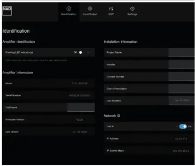
AMPLIFIER IDENTIFICATION
Flashing LED indicator(s)
- On: Entire front panel LINE INPUT LED indicators flash continuously. This is particularly useful in identifying your CI 8-150 if it is stacked in a rack among other devices.
- Off: Flashing LINE INPUT LED indicators function as intended - individually or entirely illuminate with active source or input signal(s) or not light up with no active source or input signal(s).
AMPLIFIER INFORMATION
The following pieces of information about your CI 8-150 are automatically generated and displayed.
- Model
- Serial Number
• Current Firmware Version details - Date firmware was last updated.
Another item is "Unit Name". Type or enter in the "Unit Name" tab the desired name you will identify your CI 8-150.
INSTALLATION INFORMATION
Type or enter the Installation details of the following items
- Project Name of the installation job
- Name of the Installer
- Contact number of the Installer
- Date installation was completed.
NETWORK ID
DHCP
DHCP setting controls IP Address allocation.
- DHCP On: Current IP Address is displayed. Your router dynamically assigns the IP address but may change each time CI 8-150 is powered up.
- DHCP Off: Static IP address can be manually assigned. Perform a network scan to identify unused IP address within the range of your router. Ensure that a correct IP Address is entered; otherwise, your CI 8-150 becomes inaccessible. It is advised that you must have a full understanding of network setup before making changes to the IP settings of your CI 8-150.
IP ADDRESS
- Depending upon DHCP Setting (On/Off), IP address is displayed as dynamically assigned by your router or based on the static IP address you manually entered.
IP SUBNET MASK
- Advanced network function that is best left unchanged. It is advised that only experienced network administrators make changes in this field.
INPUT/OUTPUT
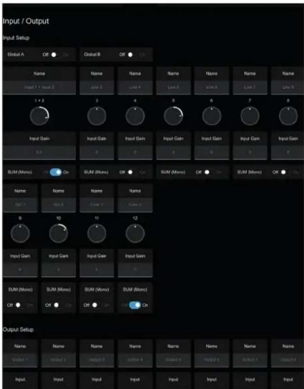
INPUT SETUP
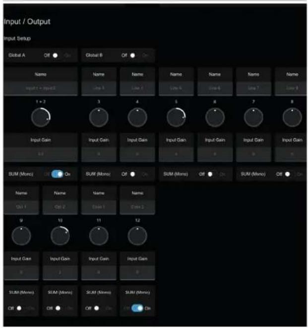
GLOBAL A, GLOBAL B - ON/OFF
- If GLOBAL A and/or GLOBAL B are turned ON, the source(s) connected to GLOBAL IN terminals will become the active input defeating all other active line input channels.
- With GLOBAL B set to ON and GLOBAL A at OFF setting, GLOBAL B input becomes the active input defeating all other active line input channels. However, if GLOBAL A is set to ON and with GLOBAL B also at ON setting, GLOBAL A input becomes the active input over all other active input channels. GLOBAL A takes priority over GLOBAL B.
NAME
- The factory default names of the eight LINE INPUT channels are Line 1 up to Line 8. Each LINE INPUT channel can be renamed by directly typing over the specific LINE INPUT. For example, type over "Line 1" with the desired name or label like "CD Player".
- The eight INPUT channels correspond to eight individual input sources connected to their respective rear panel LINE INPUT ports.
- The four digital sources with corresponding rear panel digital input ports are named Opt 1, Opt 2, Coax 1 and Coax 2.
INPUT GAIN
- Gain adjustment allows all input sources to play back at the same level so you don't need to adjust the level every time a new input source is selected. The ability to level out the input sources will also eliminate any jolting transitions when switching between input sources. It is generally preferable to reduce the level of the loudest input source rather than making louder the softer input sources.
- Grab the pointer of the INPUT GAIN knob icon and rotate to adjust gain level within ±6 dB range at 0.5 dB increments. The corresponding numerical value of the adjusted input gain level is reflected below the knob icon. You can also type directly desired input gain value in the section below the INPUT GAIN knob icon.
SUM (MONO)
- Two adjacent line input sources are summed up to provide a mono signal output. Set SUM (Mono) to "On" to combine two adjacent line input sources or "Off" to maintain stereo input sources.
OUTPUT SETUP
NAME
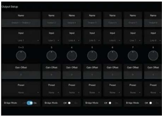
- The factory default names of the eight OUTPUT channels are Output 1 up to Output 8. Each OUTPUT channel can be renamed by directly typing over the specific OUTPUT. For example, type over "OUTPUT 1" with the desired name or label like "Living Room".
- The eight OUTPUT channels correspond to the SPEAKERS 1 to 8 respectively.
INPUT
• Each OUTPUT channel can be assigned any of the INPUT channels (Line 1-8, Optical 1-2 and Coaxial 1-2). Assign a particular OUTPUT channel with a source INPUT by selecting preferred line INPUT number from the drop down tab.
GAIN OFFSET
- Gain offset allows output channel levels to be adjusted independently.
- Grab the pointer of the GAIN OFFSET knob icon and rotate to adjust gain level within ±6 dB range at 0.5 dB increments. The corresponding numerical value of adjusted gain offset level is reflected below the knob icon. You can also type directly desired gain offset value in the section below the GAIN OFFSET knob icon.
PRESET
- Designate a DSP Preset number for the particular Output Channel. Ensure that the DSP Preset number you allocate has been previously setup and saved.
BRIDGE MODE
- Combine both adjacent output channels into Mono output by setting "Bridge Mode" to "On". Set "Bridge Mode" to "Off" to maintain stereo output.
- Refer also to item about "SPEAKERS (1-8)" under "IDENTIFICATION OF CONTROLS" for further information and guideline about Bridge Mode.
DSP
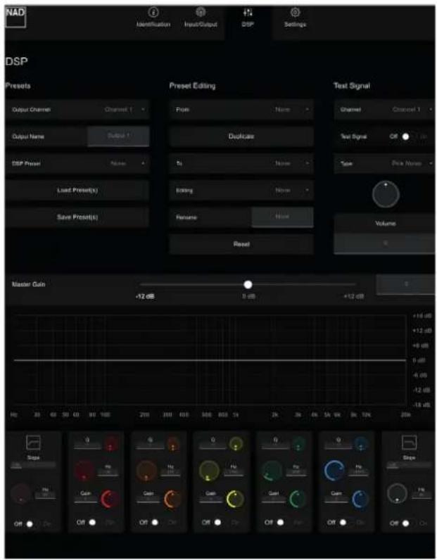
PRESETS
OUTPUT CHANNEL/OUTPUT NAME/DSP PRESET
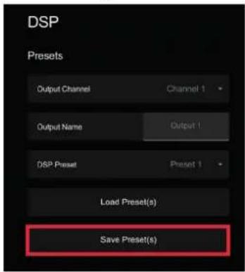
- Output Channel, Output Name and DSP Preset are combination settings that can be modified at the PRESETS section of DSP menu or OUTPUT SETUP in the INPUT/OUTPUT menu.
- Assign an Output Channel with an Output Name that can either be the default name or by typing over desired Output name. Designate a DSP Preset number for the particular Output Channel. Ensure that the DSP Preset number you allocate has been previously setup and saved.
- Any changes in Output Channel, Output Name and DSP Preset settings at the PRESETS section of DSP menu will also be reflected in the OUTPUT SETUP section of INPUT/OUTPUT menu and vice-versa.
SAVE PRESET(S)
SAVE PRESET(S) involve a combination of EDITING, adjusting, setting and saving desired Slope, Q, Frequency and Gain settings. Undertake the following steps to SAVE PRESET(S).
1 Select desired Preset number you would like to save your DSP settings. For this example, we will select "Preset 1".
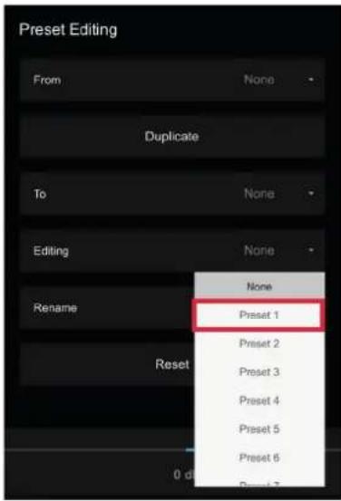
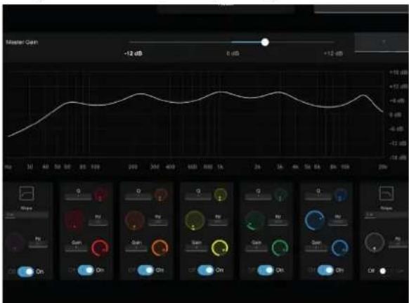
2 Adjust or set Slope, Q, Frequency and Gain settings as desired. These settings will be allocated to Preset 1 upon saving.
3 Select "Save Preset(s)" to save above Preset 1 settings.
- Select "Preset 1". Depending on your web browser, the Preset settings will be saved in your Downloads folder or may be prompted to save to a directory of your preference. Remember the Preset file name and location.
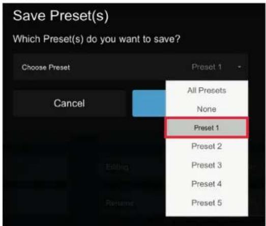
5 Repeat above process if you are going to set, allocate and save different Preset settings (up to 9 Preset settings). You can also set 9 Preset settings and then save them as "All Presets" at Step 4 above.
LOAD PRESET(S)
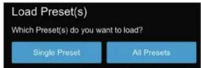
Select LOAD PRESET(S) to upload saved Preset settings/files to your amplifier. Undertake the following steps to LOAD PRESET(S).
1 Select "Load Preset(s)" to load a saved Preset file to a desired Preset number.
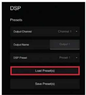
2 Select "Single Preset" if you want to load saved Preset files one at a time or "All Presets" to load saved "All Presets" at the same time. Find and select from the Preset file's location/directory the Preset number(s)/files you would like to load to your amplifier.
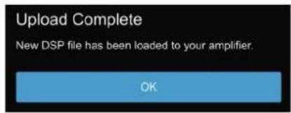
3 "Upload Complete" will be shown each time a Preset file or "All Presets" file is successfully uploaded. Slope, Q, Frequency and Gain settings are recalled, loaded and reflected in the frequency response graph upon selection of a Preset file. Check loaded Preset(s) by selecting Preset Editing → Editing → Preset number.
PRESET EDITING
DUPLICATE/FROM/TO
- Select FROM drop down tab the Preset number you will copy TO another Preset number. For example, select "Preset 1" from FROM drop down tab and then select from TO drop down tab "Preset 2". Afterwards, select "DUPLICATE" to complete the copying of Preset 1 settings to Preset 2. Current Preset 2 settings (if available) will be replaced by Preset 1 settings.
EDITING
- Use to set Slope, Q, Frequency and Gain settings and assign/save to a particular Preset. Refer also to SAVE PRESET(S) above.
RENAME
- From the EDITING drop down tab, select the Preset number you would like to rename. Upon selection of the Preset number, type in the RENAME section the Preset name you would like to call the Preset number and press ENTER.
RESET
- Selecting RESET will restore current Preset number to default settings.
TEST SIGNAL
A test signal can be sampled or loaded through all the channels. This is useful for checking audio level of each channel or comparing/balancing audio levels among the channels.
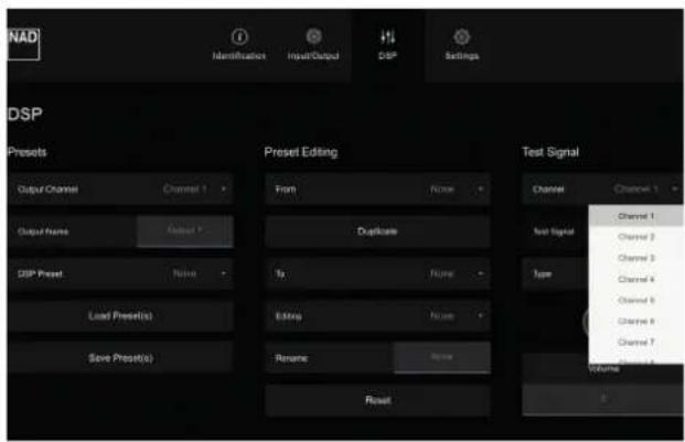
CHANNEL
- Select from the drop down tab the channel where test signal will be loaded. The test signal can be assigned to Channel 1 up to Channel 8 or select ALL for the same test signal to be loaded to all eight channels at the same time.
TEST SIGNAL
- Select ON for the test signal to be active for the selected channel. Turn off test signal by selecting OFF.
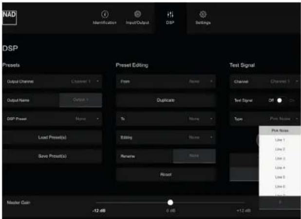
TYPE
- The test signal can be a pink noise generator or actual input signal from any of the input channels. Select from the drop down tab Pink Noise or Line1 to Line 8 to serve as test signal for specific channel or for ALL channels.
- Pink noise is useful in setting up audio and equalization levels.
VOLUME
- Grab the pointer of the VOLUME knob icon and rotate to adjust test signal audio level. The corresponding numerical value of the adjusted test signal audio level is reflected below the knob icon.
MASTER GAIN
- Adjusting Master Gain level will be simultaneously effective to all output channels. Drag the slider icon to set Master Gain level within ±12 dB range. The corresponding numerical value of adjusted Master Gain level is reflected beside the slider icon. You can also type directly desired Master Gain level in the section beside the slider icon.
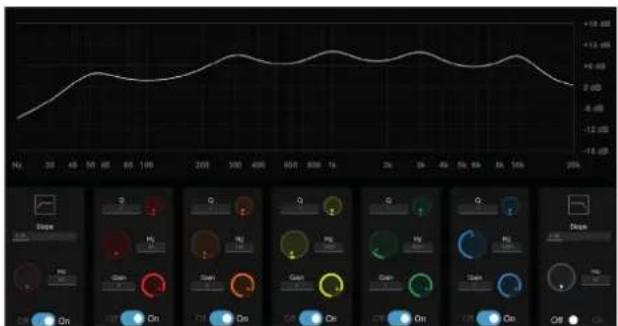
Frequency Response Graph (sample only to show response when you turn ON each parameter)
SLOPE
- Slope refers to how abruptly frequencies are attenuated by the filter once the cutoff frequency is passed. Slope is quantified in decibels per octave (dB/octave). Available selectable filter (roll off) slope values are -6dB, -12dB, -18dB and -24dB per octave.
FREQ (Hz)
- Grab the pointer of the "Hz" knob icon and rotate to set the frequency level where the filter will be enabled. The frequency range available is 20 Hz up to 20 kHz. The corresponding numerical value of adjusted frequency level is reflected beside the knob icon. You can also type directly desired frequency level in the section beside the "Hz" knob icon.
Q
- "Q" setting refers to the depth the bandwidth can be adjusted. "Q" level is from 0.1 up to 24. Bandwidth is wider at lower Q level and narrower with higher Q level.
GAIN
- Grab the pointer of the "Gain" knob icon and rotate to set the dB level the selected frequency can be increased or decreased. Gain level can be set up to 12 dB. The corresponding numerical value of adjusted dB level is reflected beside the knob icon. You can also type directly desired dB level in the section beside the "Gain" knob icon.
OFF/ON
- Enable (On) or disable (Off) the Slope, Q, Hz and Gain settings by selecting "On" or "Off" under their respective sections.
SETTINGS
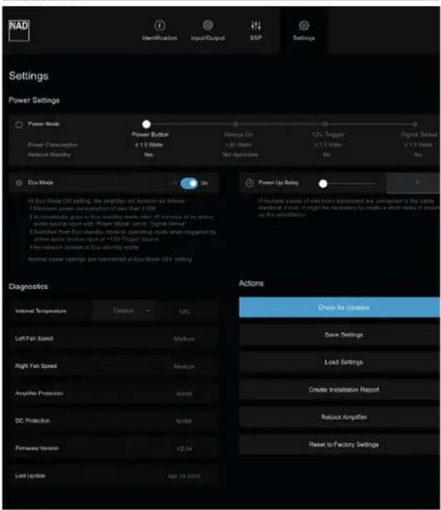
POWER SETTINGS
POWER MODE
There are four methods the CI 8-150 can be powered up. Drag the slider icon to one of the following power setting methods.
1 Power Button
2 Always On
3 12VTrigger
4 Signal Sense
POWER BUTTON
- This is the default setting. CI 8-150 is powered up and powered down by pressing front panel POWER button.
- Power consumption of CI 8-150 is less than 1W while it is at network standby mode.
NOTE
Network Standby mode maintains network connection at standby mode with reduced system performance level.
ALWAYS ON
- CI 8-150 will always be powered up and at operating mode. The unit can only be normally powered down by switching to Power Button method or unplugging the AC power cord from the mains power outlet.
- Power consumption is more than 80W while the unit remains powered up.
12V TRIGGER
- The function of powering up/down the CI 8-150 is dependent upon the presence or absence of +12V DC supply at +12V TRIGGER IN (refer also to item about +12V TRIGGER IN).
- Ensure that the rear panel 12V TRIGGER ON/OFF switch is set to ON so that 12V TRIGGER power mode can function properly.
- CI 8-150 can be switched remotely from standby mode to operating mode and vice-versa by the compatible external device where +12V TRIGGER IN -/+ terminals are connected.
- Power consumption of CI 8-150 is less than 1W in the absence of +12V DC supply at 12V TRIGGER IN.
SIGNAL SENSE
- Signal sense feature enables CI 8-150 to wake up from standby mode when triggered by active source input.
- Cl 8-150 will power up to the input source that activated the unit to operating mode.
- Power consumption of CI 8-150 is less than 1W while it is at network standby mode.
ECO MODE
At Eco Mode ON setting, the amplifier will function as follows
• Minimum power consumption of less than 0.5W.
- Automatically goes to Eco standby mode after 20 minutes of no active input signal.
- At Signal Sense power mode, unit switches from Eco Standby mode to operating mode when triggered by active input signal.
- At 12V Trigger power mode, unit switches from Eco Standby mode to operating mode when triggered by +12V Trigger source.
- No network access at Eco standby mode.
Normal power settings are maintained at Eco Mode OFF setting.
POWER UP DELAY
- Powering up CI 8-150 can be delayed by up 12 seconds. Drag the slider icon to desired time delay setting (0 to 12 seconds).
- You may use POWER UP DELAY to stagger turn on of the CI 8-150 especially if it is one of multiple pieces of electronic equipment connected to the same electrical circuit.
STANDBY MODES
| STANDBY MODE CONDITION RESULT | ||
| Standby Mode 1 (Power Button) | Method A | |
| · ECO mode : ON· Power mode: Switch from other Power Mode (Always ON, 12V Trigger, Signal Sense) to Power Button | · Unit will immediately go to standby mode after the switch to Power Button mode. | |
| Method B | ||
| · ECO mode : ON· Power mode: Currently at Power Button and unit at operating mode | · Unit will immediately go to standby mode when front panel Standby button is pressed. | |
| Standby Mode 2 (12V Trigger) | Method A | |
| · ECO mode : ON· Rear panel 12V TRIGGER switch: ON· Power mode: Switch from other Power Mode (Power Button, Always ON, Signal Sense) to 12V Trigger | · Unit will immediately go to standby mode after the switch to 12V Trigger mode. | |
| Method B | ||
| · ECO mode : ON· Rear panel 12V TRIGGER switch: ON· Power mode: Currently at 12V Trigger and unit at operating mode | · Unit will immediately go to standby mode when 12V TRIGGER source is turned off. | |
| Standby Mode 3 (Signal Sense) | Method A | |
| · ECO mode : ON· All Sources are powered down or no signal output· Power mode: Switch from other Power Mode (Power Button, Always ON, 12V Trigger) to Signal Sense | · Unit will immediately go to standby mode after the switch to Signal Sense mode. | |
| Method B | ||
| · ECO mode : ON· All Sources are powered down or no signal output· Power mode: Currently at Signal Sense and unit at operating mode | · Unit will go to network standby mode after 20 minutes of no active audio source input. | |
| Network Standby Mode 1 (Power Button) | Method A | |
| · ECO mode : OFF· Power mode: Switch from other Power Mode (Always ON, 12V Trigger, Signal Sense) to Power Button | · Unit will immediately go to standby mode after the switch to Power Button mode. | |
| Method B | ||
| · ECO mode : OFF· Power mode: Currently at Power Button and unit at operating mode | · Unit will immediately go to network standby mode when front panel Standby button is pressed. | |
| Network Standby Mode 2 (12V Trigger) | Method A | |
| · ECO mode : OFF· Rear panel 12V TRIGGER switch: ON· Power mode: Switch from other Power Mode (Power Button, Always ON, Signal Sense) to 12V Trigger | · Unit will immediately go to network standby mode after the switch to 12V Trigger mode. | |
| Method B | ||
| · ECO mode : OFF· Rear panel 12V TRIGGER switch: ON· Power mode: Currently at 12V Trigger and unit at operating mode | · Unit will immediately go to network standby mode when 12V TRIGGER source is turned off. | |
| Network Standby Mode 3 (Signal Sense) | Method A | |
| · ECO mode : OFF· All Sources are powered down or no signal output· Power mode: Switch from other Power Mode (Power Button, Always ON, 12V Trigger) to Signal Sense | · Unit will immediately go to standby mode after the switch to Signal Sense mode. | |
| Method B | ||
| · ECO mode : OFF· All Sources are powered down or no signal output· Power mode: Currently at Signal Sense and unit at operating mode | · Unit will go to network standby mode after 20 minutes of no active audio source input. | |
DIAGNOSTICS
INTERNAL TEMPERATURE
- Measurement reading of internal temperature is displayed. Unit of temperature can be displayed in either Celsius or Fahrenheit.
LEFT FAN SPEED/RIGHT FAN SPEED
There are two units of fan installed in the CI 8-150 - one in the left side and the other on the right side. Each fan starts to circulate or rotate depending upon the temperature on each channel/side (Left and right channel temperature readings are not displayed). The following are fan speed levels dependent upon temperature.
- Low speed: Fan turns on at 40 degrees Celsius; fan will stop if temperature falls below 35 degrees Celsius
- Medium speed: Fan turns on at 50 degrees Celsius; fan will switch to low speed if temperature falls below 45 degrees Celsius
- High speed: Fan turns on at 60 degrees Celsius; fan will switch to medium speed if temperature falls below 55 degrees Celsius
PROTECTION MODES
CI 8-150 has multi-levels of protection circuitry to prevent damage to your unit, external devices and speakers.
AMPLIFIER PROTECTION
- Unit will go to protect mode if short circuit of external load occurs. "Over Current" will be displayed beside "Amplifier Protection" and corresponding Line Input LED indicator of protected channel(s) will illuminate red.
- Check for any short circuit in the input and output ports connections.
DC PROTECTION
- Unit will go to protect mode if failure in amplifier module-related components occurs. "DC Error" will be displayed beside "DC Protection" and corresponding Line Input LED indicator of protected channel(s) will illuminate red.
Other protection mode indicators will pop-up should the following occur
1 Power supply section experiences over voltage or under voltage
- The amplifier has been put into protection mode as a result of a drop in voltage below normal working parameters.
- The amplifier has been put into protection mode as a result of a rise in voltage above normal working parameters.
2 Internal temperature exceeds 70 degrees Celsius
- The amplifier has been put into protection mode as a result of the temperature exceeding normal working parameters.
FIRMWARE VERSION AND LAST UPDATE
- Current firmware version and date firmware was last updated are shown.
ACTIONS
CHECK FOR UPDATES
- Select "Check for Updates" to check for any new firmware update. If new firmware details are shown, continue on with the upgrade prompt instructions to complete the upgrade process.
SAVE SETTINGS
- After finalizing all the settings and entries in the IDENTIFICATION, INPUT/OUTPUT, DSP and SETTINGS menu, select SAVE SETTINGS to save them all in one file. Depending upon your web browser, the saved settings will be saved in your Downloads folder or may be prompted to save to a directory of your preference. Remember the file name and location of the saved settings.
- You may save several settings if you want to tweak any of the menu items and save them in another file.
- This is useful when you reset your CI 8-150 to factory default settings and would like to load again previously saved settings.
LOAD SETTINGS
- Select LOAD SETTINGS if you would like to load to your CI 8-150 previously saved settings you have setup. This is the same file or one of the files in the "Save Settings" above.
- Upon selection of "Load Settings", find and select the saved settings' file name from the file location/directory. Selected saved settings' parameters are recalled and loaded to your CI 8-150.
CREATE INSTALLATION REPORT
- A report is generated showing all itemized INPUT/OUTPUT and DSP settings. You can print this report to go over and study the settings.
REBOOT AMPLIFIER
- Unit will cycle through operating mode to standby mode and back to operating mode again.
NOTE
Unit cannot be rebooted from standby mode at ECO Mode ON.
RESET TO FACTORY SETTINGS
- Your CI 8-150 will be restored to its factory default settings. All saved settings, entries and other configurations will be deleted.
- Selecting "Reset to Factory Settings" will set the standby LED from blue color (operating mode) to flashing amber color until turning to solid amber color (standby mode).
All specs are measured according to IHF 202 CEA 490-AR-2008 standard. THD is measured using AP AUX 0025 passive filter and AES 17 active filter.
GENERAL SPECIFICATIONS
LINE INPUT, SPEAKER OUT
| Continuous output power into 8 ohms >150 W (all channels driven) | |
| >180 W (two channels driven) | |
| Continuous output power into 4 ohms >180 W (all channels driven) | |
| >300 W (two channels driven) | |
| Continuous output power into 8 ohms at Bridged mode >280 W (all channels driven) | |
| >500 W (two channels driven) | |
| THD (20 Hz - 20 kHz) <0.02 % (1 W to 120 W, 8 ohms and 4 ohms) | |
| Signal-to-Noise Ratio >90 dB (A-weighted, 500 mV input, ref. 1 W out in 8 ohms) | |
| Clipping power (All channels driven) >160 W (1 kHz 8 ohms 0.1 % THD) | |
| >200 W (1 kHz 4 ohms 0.1 % THD) | |
| Clipping power into 8 ohms at Bridged mode >300 W (1 kHz 0.1 % THD - all channels driven) | |
| >550 W (1 kHz 0.1 % THD - two channels driven) | |
| IHF dynamic power (all channels driven) 8 ohms: 180 W | |
| 4 ohms: 280 W | |
| 2 ohms: 360 W | |
| IHF dynamic power (two channels driven) 8 ohms: 200 W | |
| 4 ohms: 360 W | |
| 2 ohms: 600 W | |
| IHF dynamic power (Bridged mode, all channels driven) 8 ohms: 520 W | |
| 4 ohms: 670 W | |
| IHF dynamic power (Bridged mode, two channels driven) 8 ohms: 600 W | |
| 4 ohms: 800 W | |
| Peak output current >26 A (1 ohm, 1 ms) | |
| Damping factor >150 (ref. 8 ohms, 20 Hz to 6.5 kHz) | |
| Frequency response ±0.5 dB (20 Hz - 20 kHz) | |
| Channel separation | >75 dB (1 kHz) |
| >65 dB (10 kHz) | |
| Maximum undistorted input level | 3300 mV |
| Input sensitivity (for 150 W in 8 ohms, maximum volume) | 1450 mV |
| Analog Input audio sense threshold (one channel with signal) | 3 ± 0.5 mVrms (ref. 100 Hz - 10 kHz) |
| Trigger IN level | 3 - 30 Vdc |
| Standby power | 0.5 W |
DIMENSION AND WEIGHT
| Gross dimensions (W x H x D)* | 483 x 90 x 435 mm |
| 19 116 x 3 316 x 17 316 inches | |
| Shipping weight | 17.6 kg (38.8 lbs) |
* - Gross dimension includes extended rear panel terminals and excludes installed feet
Specifications are subject to change without notice. Check out www.NADElectronics.com for updated documentation or latest information about CI 8-150.
POWER CONSUMPTION AND HEAT OUTPUT
| CONDITION | 230 V/50 HZ 120 V/60 HZ | ||||
| POWER CONSUMPTION (W) | HEAT OUTPUT (BTU/HR) | POWER CONSUMPTION (W) | HEAT OUTPUT (BTU/HR) | ||
| Eco Mode Standby Power at 8 ohms 0.4 1.4 0.4 1.3 | |||||
| Network Standby Power at 8 ohms 1.2 4.2 1.2 4.1 | |||||
| Idle power at 8 ohms 86 295 88 299 | |||||
| Output power at 8 ohms, all channels driven | 1/8 rated power 243 826 246 836 | ||||
| 1/3 rated power 529 1799 540 1836 | |||||
| 1/2 rated power 758 2577 781 2655 | |||||
| Full rated power 1512 5140 1557 5294 | |||||
| Output power at 4 ohms, all channels driven | 1/8 rated power 251 853 255 867 | ||||
| 1/3 rated power 552 1877 561 1907 | |||||
| 1/2 rated power 790 2686 813 2764 | |||||
| Full rated power 1540 5236 1600 5440 | |||||
Specifications are subject to change without notice. Check out www.NADElectronics.com for updated documentation or lates information about C1 8-150.

www.NADelectronics.com
©2021 NAD ELECTRONICS INTERNATIONAL
A DIVISION OF LENBROOK INDUSTRIES LIMITED
All rights reserved. NAD and the NAD logo are trademarks of NAD Electronics International, a division of Lenbrook Industries Limited.
No part of this publication may be reproduced, stored or transmitted in any form without the written permission of NAD Electronics International.
While every effort has been made to ensure the contents are accurate at the time of publication, features and specifications may be subject to change without prior notice.
- WARNING
- CAUTION REGARDING PLACEMENT
- FCC STATEMENT
- CAUTION
- RESPONSIBLE PARTY
- NOTES ON ENVIRONMENTAL PROTECTION
- INFORMATION ABOUT COLLECTION AND DISPOSAL OF WASTE BATTERIES (DIRECTIVE 2006/66/EC OF THE EUROPEAN PARLIAMENT AND THE COUNCIL OF EUROPEAN UNION) (FOR EUROPEAN CUSTOMERS ONLY)
- WHAT'S IN THE BOX
- QUICK START
- IMPORTANT SETUP NOTES
- SAVE THE PACKAGING
- ATTENTION!
- POWER BUTTON
- NOTE
- STANDBY LED
- LINE INPUT (1 - 8) LED INDICATORS
- IMPORTANT NOTICE
- OPTICAL IN 1-2/COAXIAL IN 1-2
- GLOBAL A, GLOBAL B IN/OUT
- GLOBAL A IN, GLOBAL B IN
- GLOBAL A OUT, GLOBAL B OUT
- LINE INPUT (1-8)
- FUSE HOLDER
- LAN
- NOTES
- +12V TRIGGER IN
- +12V TRIGGER IN - ON/OFF
- +12V TRIGGER IN +/-
- IR IN/OUT
- RESET
- SPEAKERS (1 - 8)
- AC MAINS INPUT
- USER INTERFACE
- GUIDELINE FOR NETWORK SETUP CONNECTION
- IMPORTANT NOTES
- IMPORTANT
- FIRMWARE UPGRADE PROCEDURE
- MAIN MENU OPTIONS
- AMPLIFIER IDENTIFICATION
- Flashing LED indicator(s)
- AMPLIFIER INFORMATION
- INSTALLATION INFORMATION
- NETWORK ID
- DHCP
- IP ADDRESS
- IP SUBNET MASK
- GLOBAL A, GLOBAL B - ON/OFF
- NAME
- INPUT GAIN
- SUM (MONO)
- INPUT
- GAIN OFFSET
- PRESET
- BRIDGE MODE
- PRESETS
- OUTPUT CHANNEL/OUTPUT NAME/DSP PRESET
- SAVE PRESET(S)
- LOAD PRESET(S)
- PRESET EDITING
- DUPLICATE/FROM/TO
- EDITING
- RENAME
- RESET
- TEST SIGNAL
- CHANNEL
- TYPE
- VOLUME
- MASTER GAIN
- SLOPE
- FREQ (Hz)
- Q
- GAIN
- OFF/ON
- POWER SETTINGS
- POWER MODE
- POWER BUTTON
- ALWAYS ON
- 12V TRIGGER
- SIGNAL SENSE
- ECO MODE
- POWER UP DELAY
- DIAGNOSTICS
- INTERNAL TEMPERATURE
- LEFT FAN SPEED/RIGHT FAN SPEED
- PROTECTION MODES
- AMPLIFIER PROTECTION
- DC PROTECTION
- FIRMWARE VERSION AND LAST UPDATE
- ACTIONS
- CHECK FOR UPDATES
- SAVE SETTINGS
- LOAD SETTINGS
- CREATE INSTALLATION REPORT
- REBOOT AMPLIFIER
- RESET TO FACTORY SETTINGS
- ©2021 NAD ELECTRONICS INTERNATIONAL
- A DIVISION OF LENBROOK INDUSTRIES LIMITED
Brand : NAD
Model : CI 8-150 DSP
Category : Receiver