
RC+ Express - Uncategorized EPSON - Free user manual and instructions
Find the device manual for free RC+ Express EPSON in PDF.


| Product Type | Robot Programming Software (6-Axis/SCARA) |
| Manufacturer | Seiko Epson Corporation |
| Version | 1.0 (Rev.5, 2021-2022) |
| Supported Robots | LS-B, LS3-B401S-V1, T, T-B, G (except G1), GX, C, C4, C8, C12, VT Series (table top only) |
| Supported Controllers | RC90-B, RC700-A, RC700-D; firmware 7.5.1.0 or later (7.5.3.0 for Advanced) |
| Operating System | Windows 10 Pro 64-bit |
| Minimum CPU | Core i3 or greater; recommended Core i5 |
| Minimum Memory | 2 GB or more |
| Minimum Storage | 4 GB or more |
| Display Requirements | 1280x760 or larger, horizontal; DirectX 10.1 and OpenGL 2.1 |
| Connection Methods | USB (Type-B), Ethernet (LAN), Virtual (simulation) |
| Programming Method | Drag-and-drop graphical interface; templates and SPEL+ commands |
| Program Templates | Simple Pick & Place, Simple Palletizing, Empty Program; RC+ Project Link templates |
| Languages Supported | Multiple including English, French, German, Spanish, Japanese, Chinese, etc. |
| Maintenance Features | Parts consumption monitoring (battery, grease, belt, motor, gear), backup/restore |
| Safety Features | Rehearsal mode (low power), emergency stop, safety door monitoring, error/warning pop-ups |
| Advanced Options | RC+ Express Advanced License (RC+ Project Link, SPEL+ commands) |
| Documentation | Built-in manual with search, bookmarks, print; 220 pages PDF |
Frequently Asked Questions - RC+ Express EPSON
User questions about RC+ Express EPSON
0 question about this device. Answer the ones you know or ask your own.
Ask a new question about this device
Download the instructions for your Uncategorized in PDF format for free! Find your manual RC+ Express - EPSON and take your electronic device back in hand. On this page are published all the documents necessary for the use of your device. RC+ Express by EPSON.
USER MANUAL RC+ Express EPSON
Original instructions
6-Axis
EPSON RC+ Express Manual
Rev.5
©Seiko Epson Corporation 2021-2022
FOREWORD
Thank you for purchasing our software.
This manual contains the information necessary for the correct use of the software. Please carefully read this manual and other related manuals before installing the software.
Keep this manual handy for easy access at all times.
The software and its optional parts are shipped to our customers only after being subjected to the strictest quality controls, tests, and inspections to certify its compliance with our high performance standards. Please note that the basic performance of the product will not be exhibited if our software is used outside of the usage conditions and product specifications described in the manuals.
This manual describes possible dangers and consequences that we can foresee. Be sure to comply with safety precautions on this manual to use our software safety and correctly.
TRADEMARKS
Microsoft, Windows and Windows logo are either registered trademarks or trademarks of Microsoft Corporation in the United States and/or other countries.
Other brand and product names are trademarks or registered trademarks of the respective holders.
TRADEMARK NOTATION IN THIS MANUAL
Microsoft® Windows® 10 Operating system
Throughout this manual, Windows 10 refer to above respective operating systems.
In some cases, Windows refers generically to Windows 10.
NOTICE
No part of this manual may be copied or reproduced without authorization.
The contents of this manual are subject to change without notice.
Please notify us if you should find any errors in this manual or if you have any comments regarding its contents.
MANUFACTURER
SEIKO EPSON CORPORATION
CONTACT INFORMATION
Contact information is described in “SUPPLIERS” in the first pages of the following manual:
Robot System Safety Manual Read this manual first
MANUALS
Symbols
Each symbol has following meanings.

This symbol indicates that a danger of possible harm to people or physical damage to equipment and facilities exists if the associated instructions are not followed properly.

This symbol describes important information to be followed for operating the Robot system. This symbol indicates that handling the product incorrectly may cause a malfunction or failure of the product.

This symbol describes hints or additional explanations for easier or alternative operations.
How to Read a Manual
To read a manual, tap the <?> button left of screen.
The description about the current screen is displayed, or TOP page is displayed.

The recommended browser is Microsoft Edge (Version: 86 or later).
Regarding screens and illustrations
- The illustrations used in this manual are examples. Depending on the model you are using, the screen and illustration may vary, but operation procedures are the same.
- In this manual, EPSON RC+ Express Edition may be referred to as "RC+ EE".
How to display tips and hints
The description about the current screen is displayed.
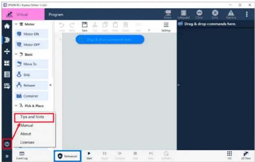
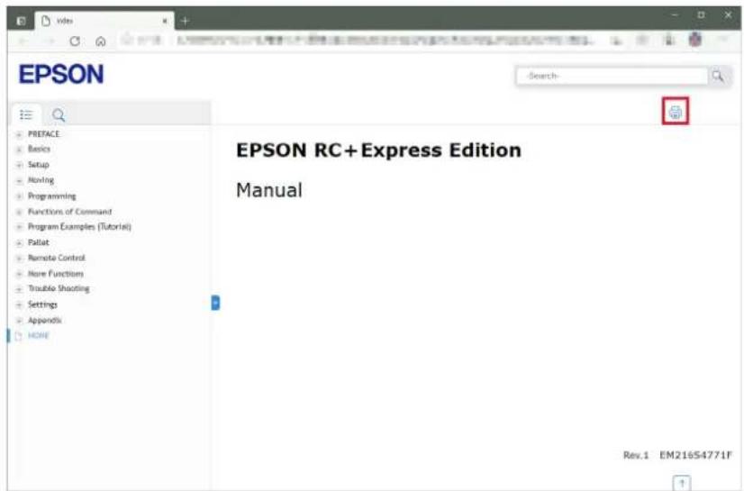
How to display a Manual
TOP page of a manual is displayed. You can search by keyword, jump to the corresponding page from a bookmark, or print, etc.
When you close the page, tap the
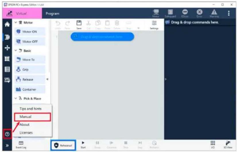

The TOP page of the manual can also be opened by the following procedure:
Windows Start menu - EPSON RC+ Express Edition - Manual
The useful functions are as follows:
- Searching by keyword
Enter a keyword in the search window and tap to display the corresponding page. Tap the title to jump to the corresponding page.
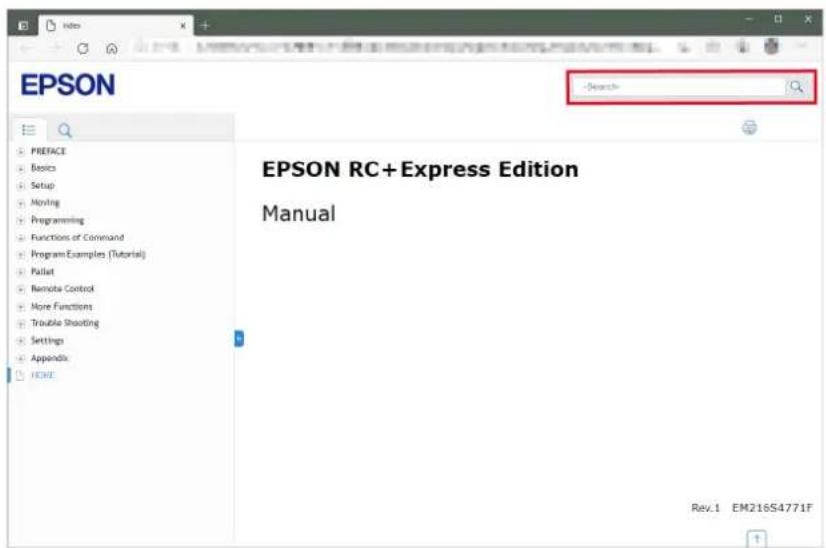
- Jumping to the corresponding page from a bookmark
Tap the bookmark title displayed on the left side of the screen to display the titles in the lower outline level. Tap the title to jump to the corresponding page.
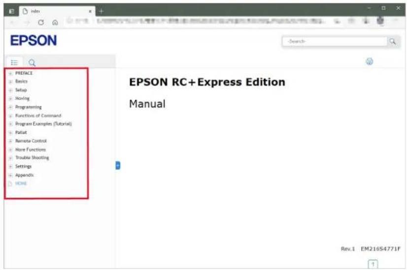
- Printing

Tap on the page to print.
- How to move a manual
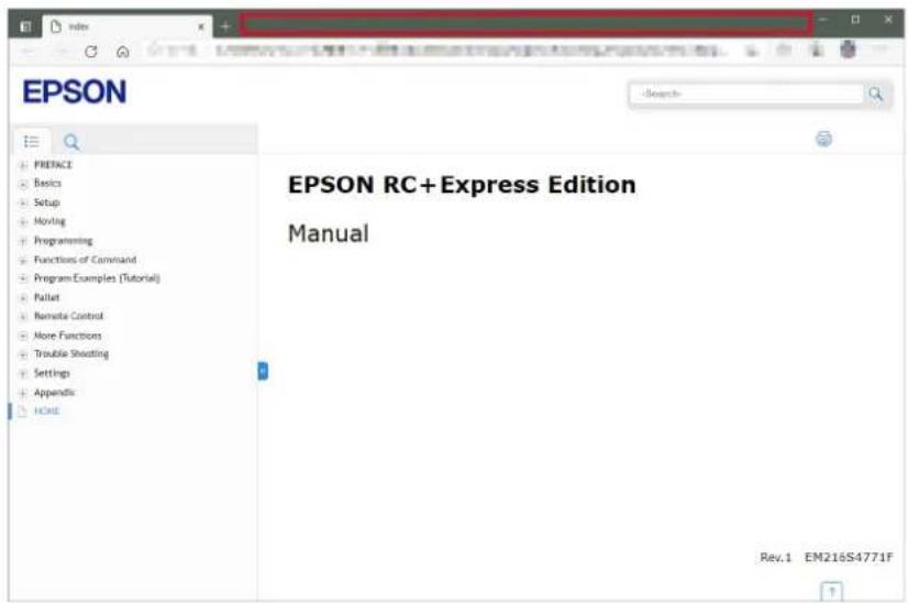
Swipe the top of the screen to move the manual position freely. This is convenient when you arrange the manual and software side by side.
You can zoom in/out by dragging the outer frame of the screen.
How to Read RC+ Manual
This manual has some pages which refer to the EPSON RC+ manual.
To refer to the RC+ manual, install EPSON RC+ and select the manual from the Windows Start menu - [EPSON RC+ 7.0].
You can also refer to the RC+ manual from EPSON RC+ 7.0 menu - [Help] - [Manuals].
The manuals referred to by this software are as follows:
| Manual title Contents | |
| Safety Manual | Precautions for safety use of the robot system and contact information |
| EPSON RC+ User's Guide | How to use and set the robot system and EPSON RC+ |
| SPEL+ Language Reference | Contents of SPEL+ (robot programming language) |
| Manipulator Manual | Robot specifications, installation, settings and maintenance methods |
| Controller Manual | Controller specifications, installation, settings and maintenance methods |
| Robot Controller Option Fieldbus I/O | How to use Fieldbus I/O (controller option) |
Basics 1
What's EPSON RC+ Express Edition?......1
System Configuration....1
Supported Robots 2
Operating Environments ....3
How to Operate a Tablet ....3
Setup 5
Advanced Preparations....5
Installing the Software....5
Connecting to Robot....9
Home screen....19
Closing the Software....26
Operating Robot 27
Main Monitor 27
Operating Robot....39
Programming 41
Program Screen Layout....41
Creating/Editing/Managing a Program 45
Functions of Command 65
About Command....65
Command Function List: 67
Various Program Examples (Tutorial) 95
Pick and Place (between 2 points)....95
Pick and Place (between 3 points)....101
Palletizing....106
Sorting Non-defective/Defective Products....115
Fixed Cycle Signal Output (RC+ Project Link) 123
Cycle Time Measurement (RC+ Project Link) 129
Pallet 133
Pallet Configuration.... 133
Creating a New Pallet 134
Point File Viewer 137
Point File Viewer Screen 137
Defining a Point....138
Remote Control 141
Remote I/O in This Software....141
Using Remote I/O 141
Using Remote Ethernet 145
Setting I/O Functions 148
More Functions 153
Registering Custom Template....153
Exporting and Importing a Program....156
SPEL+ Code Viewer....159
Program Protect Mode....160
RC+ Project Link 161
Overview of the feature of RC+ Project Link....161
Conditions to Use RC+ Project Link....161
Creating RC+ Project....162
Setup for RC+ and Building the Project....167
Importing RC+ Project on RC+ EE 168
Creating a Program Using Imported Commands 169
Executing a Program Using RC+ Project Link 170
Trouble Shooting 171
The icon at the top of the screen lights up 171
Powered off accidentally while editing program....171
Connecting to robot failed....172
I want operation speed of the robot to move faster....173
[Arm reached the limit of motion range.] message showed up....173
Troubles when using RC+ Project Link 174
Robot is in singular postures 175
Failed in Rollback 176
Settings 177
Robot Settings 177
System Settings....178
Hand Settings.... 184
Language Settings.... 190
Maintenance.... 191
Rebooting Controller 200
Appendix 203
Version 203
Licenses 204
Uninstalling....207
List of SPEL+ Command Availability in RC+ Project Link 208
Basics
What's EPSON RC+ Express Edition?
You can build simple application fast and easily regardless of your robotics skills by using EPSON RC+ Express Edition.
EPSON RC+ Express Edition will help you:
- Create robot program by drag and drop.
- Operate a robot intuitively with the touch UI on a tablet PC.
- Build simple pick-and-place or palletizing applications quickly using templates.
System Configuration
The system configuration of this software is as follows.
Connect the controller and your tablet with a LAN (Ethernet communication) cable or a USB cable.
Operating Environments

- Customers are responsible for preparing the cables required for connection.
- A tablet is recommended, but it can also be used on a standard PC.
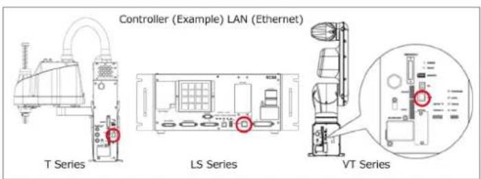
LAN (Ethernet)cable
USB cable
Supported Robots
This version of the software can connect to following combinations of robot and controller:
Version
| Robot | Controller | Controller Firmware | |
| LS-B Series | Except LS3-B401S-V1 | RC90-B | Ver.7.5.1.0 or later |
| LS3-B401S-V1 | Ver.7.5.1.2 or later | ||
| T Series Ver.7.5.51.0 or later | |||
| T-B Series Ver.7.5.51.1 or later | |||
| G Series (3 axis G1 is not supported.) RC700-A Ver.7.5.1.0 or later | |||
| GX Series RC700-D Ver.7.5.1.2 or later | |||
| C Series | C4 Series RC700, RC700-A | Ver.7.5.1.0 or later | |
| C8 Series | RC700-A | ||
| C12 Series | |||
| VT Series Ver.7.5.51.0 or later | |||

Only table top mounting specification is supported.
Wall mounting and ceiling mounting are not supported.
If you use RC+ Express Advanced, make sure your controller firmware version is following.
RC90/RC700 series 7.5.3.0 or later
T/T-B/VT series 7.5.53.0 or later

To use the feature of RC+ Express Advanced, install 7.5.3 or later version of EPSON RC+ on a PC installed RC+ EE.
Overview of the feature of RC+ Project Link
Operating Environments
The recommended operating environments for this software are as follows. Prepare a tablet with Windows which meets the following conditions.

We recommend to use a tablet. You can also use a PC.
| Item Description | |
| OS | Windows 10 Pro 64-bit version |
| CPU | Recommended environment: Core i5 or greaterMinimum environment: Core i3 or greater |
| GPU | Operates DirectX10.1 or laterCorresponds OpenGL2.1 or later |
| Memory | 2GB or more |
| HDD/SSD capacity | 4GB or more |
| Display | 1280x760 or larger (horizontal display) |
How to Operate a Tablet
This software supports the following touch UI.
| Item | Operation | Description | |
| Tap |  | Press or select a button or item. | |
| Double-tap | 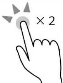 | Tap twice. | |
| Flick | 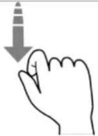 | Scroll the screen quickly. | |
| Swipe | 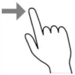 | Press and hold down an item and move it side to side and up and down. | |
| Drag and drop | 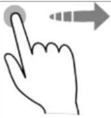 | Press and hold down an item and move it, then release it at the location to insert. | |
| Pinch in Pinch out | 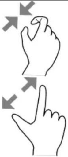 | Operate to zoom in or out an image (only on 3D View). | |
Setup
Advanced Preparations
Prepare following items before using this software.
- Tablet (recommended), or PC
This software is created for the touch UI. We recommend to use a tablet. You can also use a PC.
Operating Environments
- DVD drive
- Cables
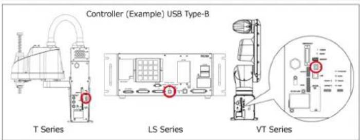
For USB connection: USB cable

- The connector shape of the robot and controller is Type-B.
- You can put a conversion cable in between. Prepare if necessary.
For Ethernet connection: LAN (Ethernet communication) cable

- When you use a PC which does not have a wired LAN interface, an external Ethernet adapter is required.
- To communicate via Ethernet, a robot must be connected to the network and the settings must be completed.
Installing the Software
Installing (From DVD Drive)
This page describes the procedures to install this software from DVD drive. Operation procedure
- Log on to your tablet with administrator privilege.
If anything is unclear, consult the administrator of the tablet.
- Close all running applications.
When you install the software while other applications are running, it may not work properly.
-
Insert the supplied DVD into your PC's DVD drive.
-
When the following screen is displayed, click
button.
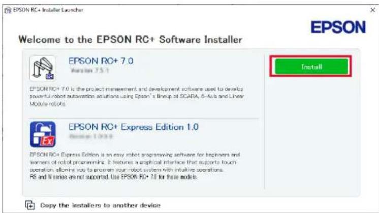

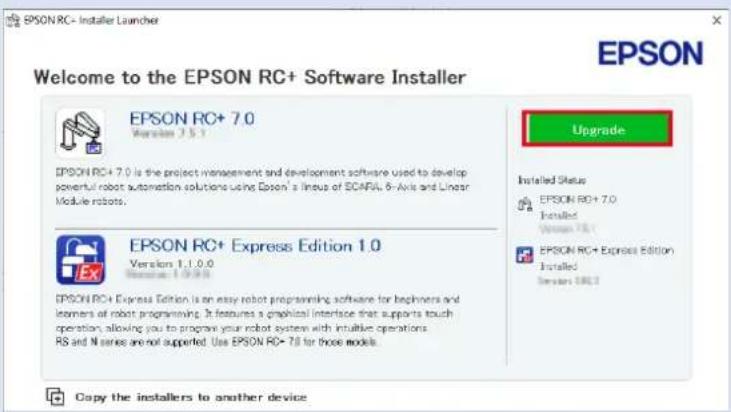
If the software is already installed, [Maintenance] is displayed. If your software version is old, [Upgrade] is displayed. If needed, click [Upgrade] and upgrade.
- Follow the instructions on the screen to install.
To uninstall, refer to the following: Uninstalling
Installing (From USB, Shared Folder)
This page describes how to install this software to a tablet or a PC which does not have a DVD drive.
Operation procedure
-
To copy the installer, insert the supplied DVD into your PC's DVD drive. By using PC with DVD drive, copy the installer to USB memory stick or shared folder on the local network.
-
When the following screen is displayed, click [Copy the installers to another device] on the auto play screen.
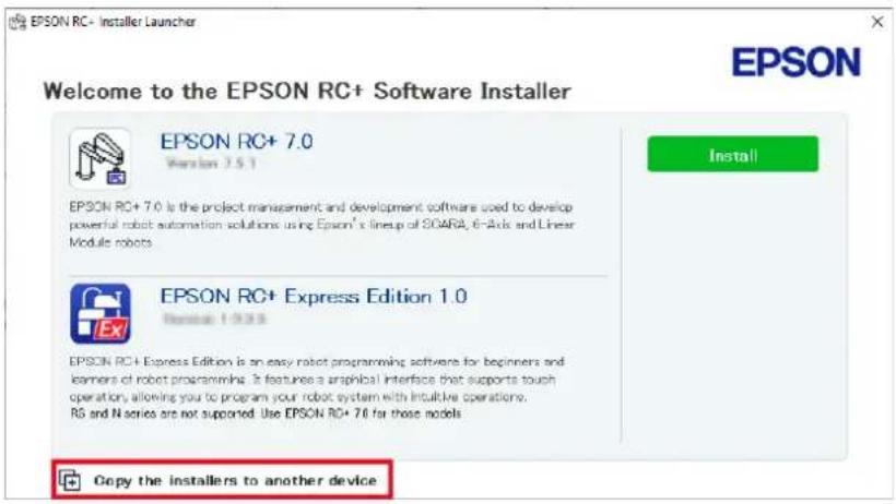

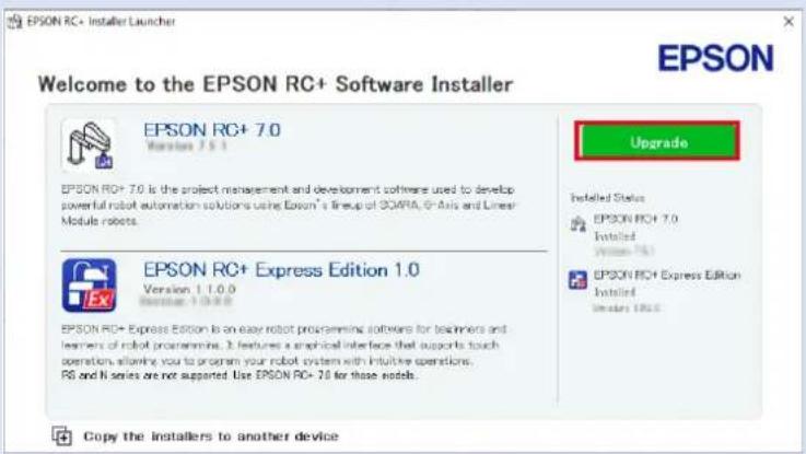
If the software is already installed, [Maintenance] is displayed. If your software version is old, [Upgrade] is displayed. If needed, click [Upgrade] and upgrade.
- Specify a folder of the installer and tap the
button.
Save them in USB memory stick or shared folder.
- Open the saved installer with the tablet or PC to use this software.
When you use USB memory stick, insert it your tablet or PC and open the folder in explorer.
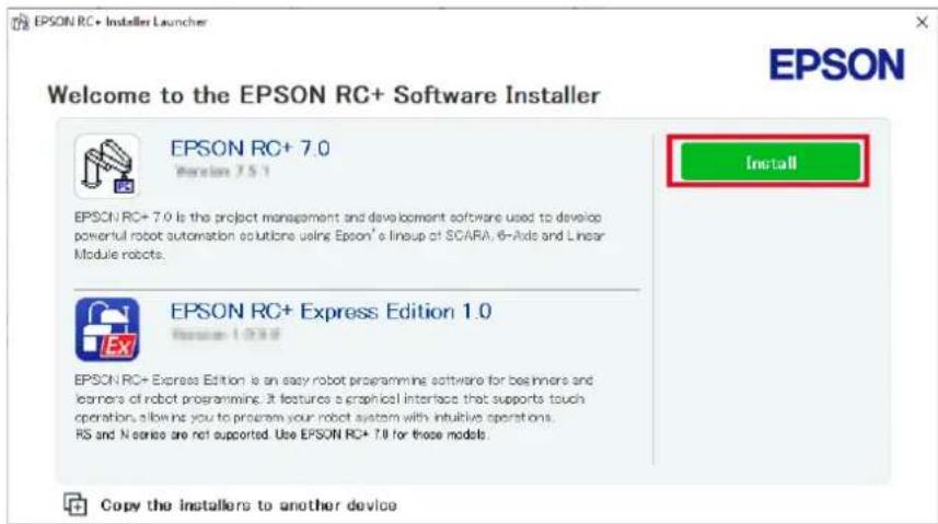
- When following appeared, tap [Install].
- Follow the instructions on the screen to install.
To uninstall, refer to the following:
Uninstalling
Enabling the RC+ Express Advanced
Contact suppliers or distributors to obtain the "RC+ Express Advanced" (Epson RC+ 7.0 Express Edition Advanced License) of this software.
Contact information is described in "SUPPLIERS" in the first pages of the following manual:
Robot System Safety Manual Read this manual first
To enable/disable the controller option, refer to following.
Options
Connecting to Robot
Connecting to Robot (USB)
This page describes how to connect Controller to tablet using USB cable.

Trial version of this software can only connect to the virtual robot. Connecting to Virtual Robot

If the PC goes to sleep when the robot is connected, communication with the controller will be disconnected. Set it so that it does not go to sleep, or try again from the robot connection when waking up from sleep.
Operation procedure
1. Connect the Controller and the tablet using USB cable.
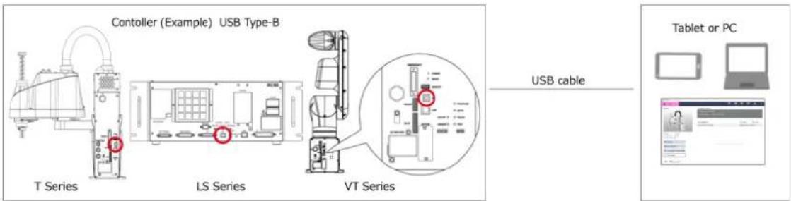

- The connector shape of the robot and controller is Type-B.
- You can put a conversion cable in between.

2. Double-tap
to launch the software.
- When the following screen appears, tap [Setup connection].
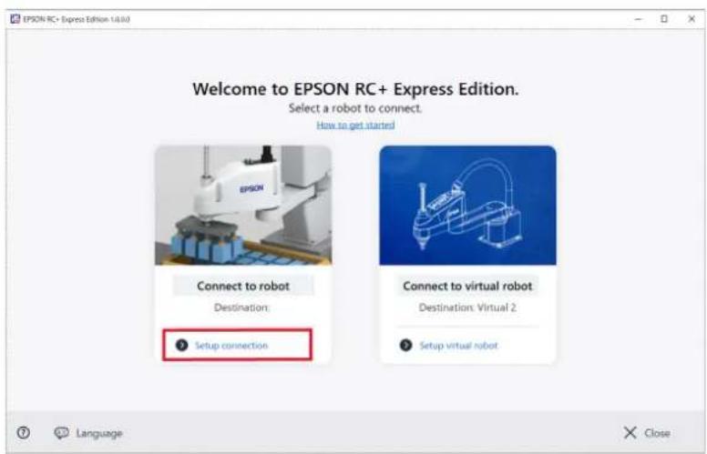

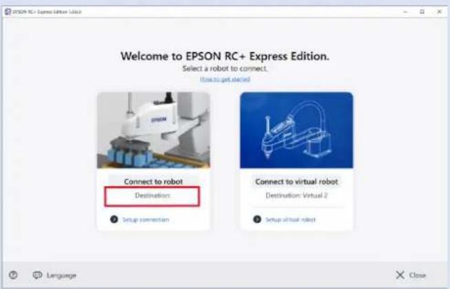
- Tap [Language] to change the display language. - If the connection setting is completed, it is displayed as USB in "Destination". If you don't need to change the Destination, tap [Connect to robot].
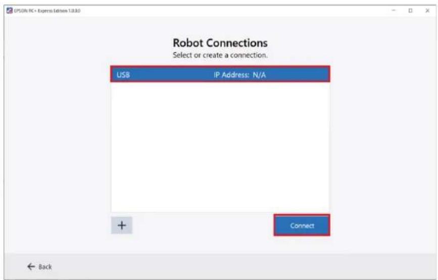
4. Choose the USB connection, and tap button.
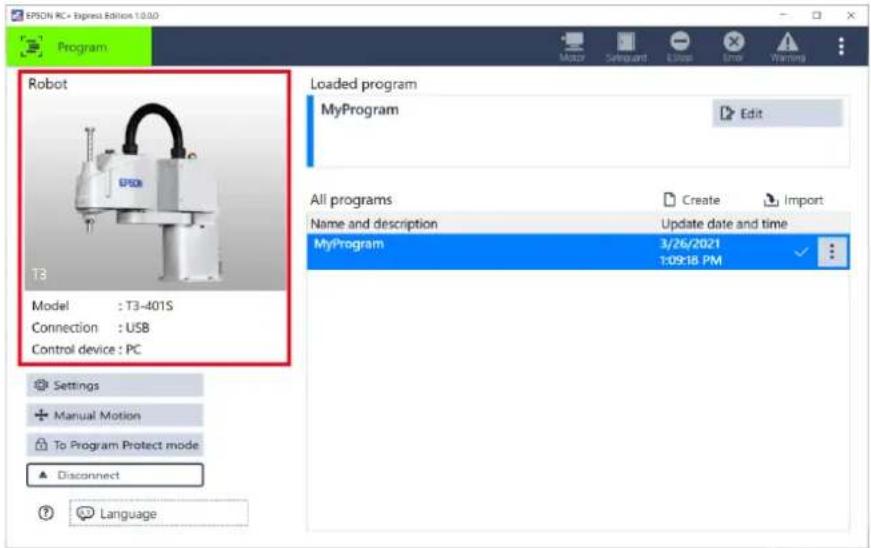
When the connection is established, the screen transits to the Home. [Program] on the upper left of the screen indicates that the connection to the robot is properly established.
Information of the robot is displayed in Home as shown below.
If the connection fails, refer to the following. Connecting to robot failed
Connecting to Robot (Ethernet)
This page describes how to connect to the Controller to tablet using Ethernet cable.

Before you can connect to the robot with Ethernet, it must be properly configured and online in the network.
To configure the network settings of the robot, connect to it with USB and set "IP Address", "Subnet mask" and "Default gateway" in Settings.
Controller Configuration
Network settings of the controller at the time of shipment is shown below.
IP Address: 192.168.0.1
Subnet mask: 255.255.255.0
Default gateway: 0.0.0.0
- When you use the trial software, the software cannot connect to the robot.
Connecting to Virtual Robot
Connecting to Virtual Robot

If the PC goes to sleep when the robot is connected, communication with the controller will be disconnected.
Set it so that it does not go to sleep, or try again from the robot connection when waking up from sleep.
Operation procedure
- Connect Controller to tablet using LAN cable (Ethernet connection).
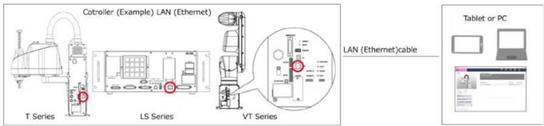

If you are using a PC without LAN interface, you need an external LAN adapter.

- Double-tap to launch the software.
- When following appears, tap [Setup connection].
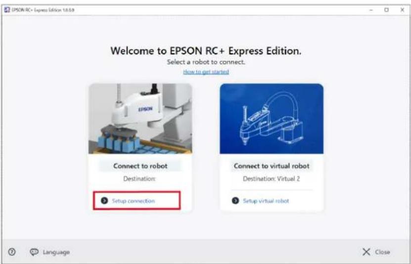

- Tap [Language] to change the display language.
- When the connection setting is done before, the name of the connection is displayed at Destination.
When you don't need to change the Destination, tap [Connect to robot].
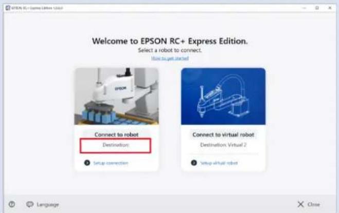
4. Tap the <+> button.
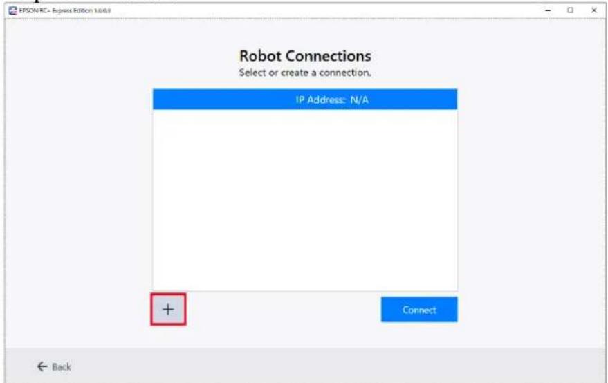
5. When following appeared, fill the blanks and tap the button.
If you want to change the password for connecting controller, tap
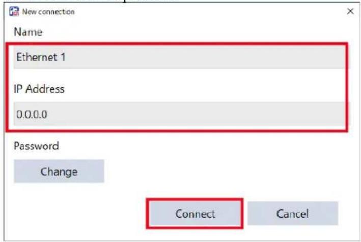

When connecting to a controller which has global IP address using Ethernet cable, password authentication is needed.
Be sure to use an IP address in the following private IP address ranges unless a global IP address is required.
| Private IP Address Ranges |
| 10.0.0.1 ~ 10.255.255.254 |
| 172.16.0.1 ~ 172.31.255.254 |
| 192.168.0.1 ~ 192.168.255.254 |
For the details, see below. EPSON RC+ User's Guide
- Choose the Ethernet connection, and tap the
button.
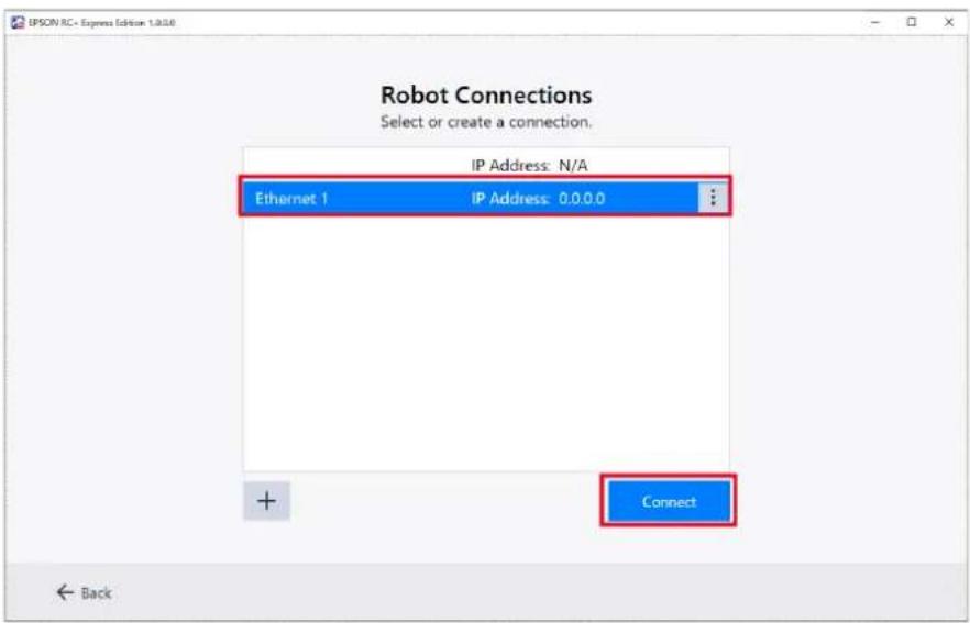
When the connection is established, the screen transits to the Home. Green [Program] on the upper left of the screen indicates that the connection to the robot is established properly.
Information of the robot is displayed in Home as shown below.
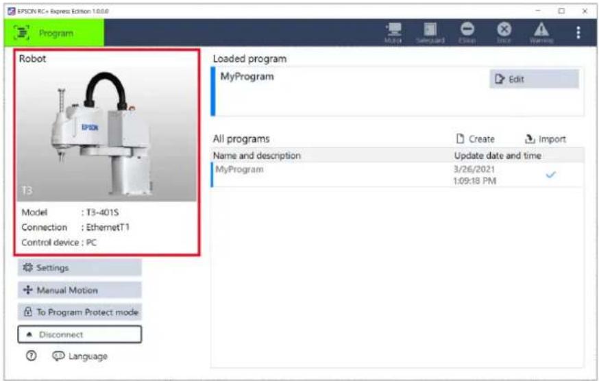
When failed in connecting to robot, refer to the following. Connecting to robot failed
Connecting to Virtual Robot
This page describes how to connect to Virtual Robot.
You can operate and program a robot in the virtual environment without connecting to a real robot.

Trial version of this software only offers the virtual robot connection.

If the PC goes to sleep while connected to the virtual robot, the operation of this software may become unstable.
Set the PC so that it does not go to sleep, or try again from the connection when waking up from sleep.
Operation procedure

-
Double-tap to launch the software.
-
When following appears, tap [Setup virtual robot].
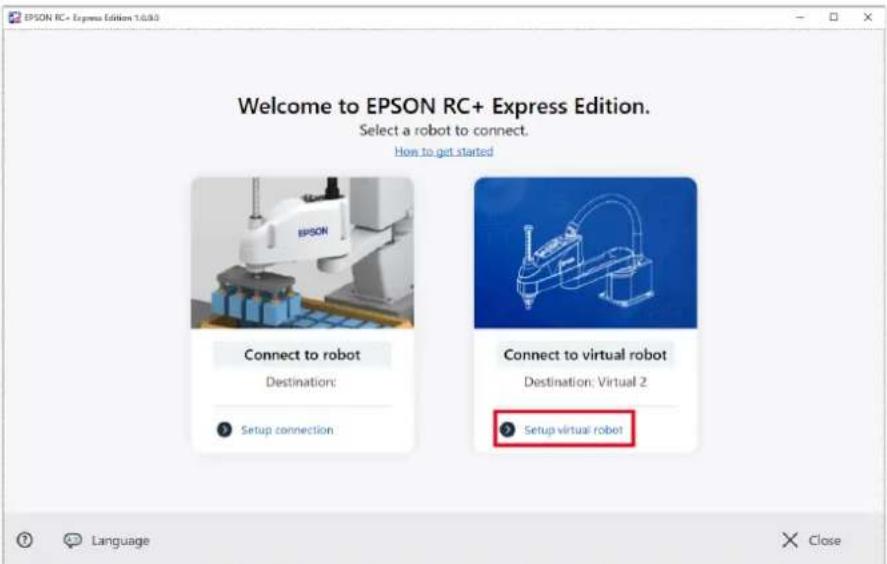

- Tap [Language] to change your languages.
- If the connection setting is done before, virtual robot name may be displayed at "Destination". If you don't need to change the Destination, you can skip the following steps and just tap [Connect to virtual robot].
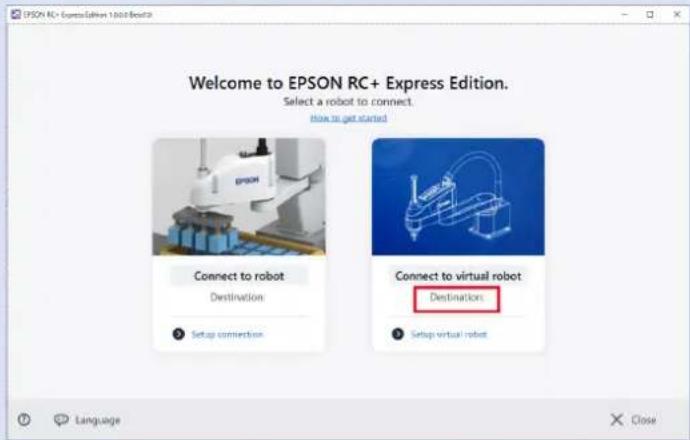
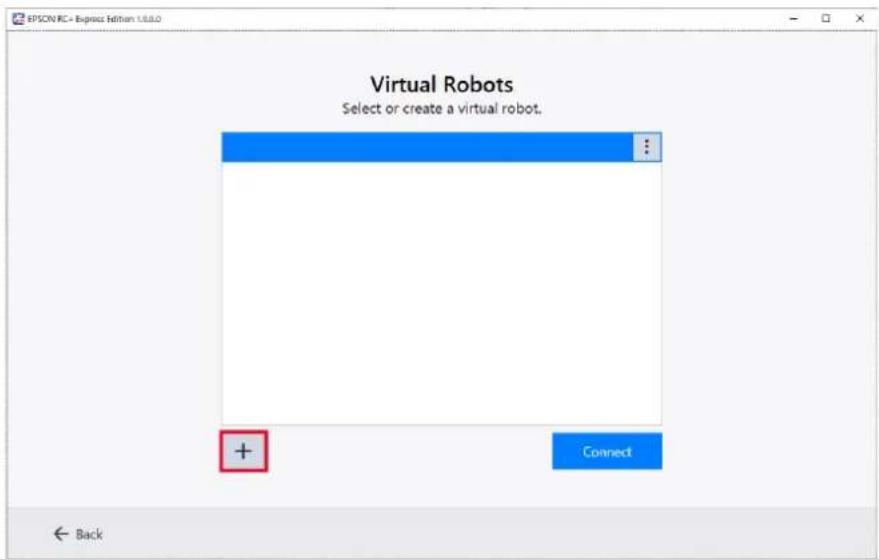
- Tap the <+> button.
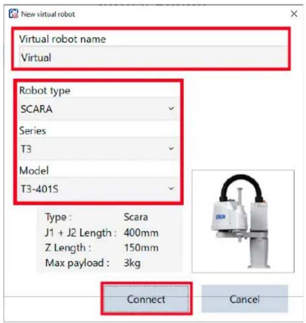
- When following appeared, fill the blanks and tap the
button.
When the connection is established, the screen transits to the Home. [Virtual] on the upper left of the screen indicates that the connection to the virtual robot is properly established.
Information of the robot is displayed in Home as shown below.
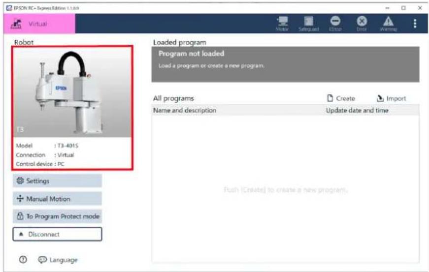
Home screen
Home Screen
When connection is established, the screen transits to the Home screen.
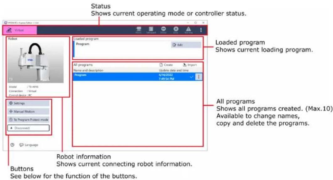
Button functions
| Buttons Description | |
| To Program Protect mode | A program is protected. Program edit function is partially restricted.Program Protect Mode |
| Edit | A program can be edited.When the program is protected, thebutton appears. |
| Settings | - Hand SettingsSettings of the hand installed to the robot.Hand Settings- System SettingsDetailed Controller settings.System Settings- MaintenanceBackup/restoration of the Controller data & parts maintenance. Checking part consumption rate.Maintenance |
| Manual Motion | Operate robot on viewing 3D View to check the motion.Operating Robot |
| Disconnect | Disconnect from Controller. |
Status Bar
Status bar on the top of the screen shows current operating mode and status of the controller.

Operating mode
Indicates current mode of the robot controller.
| Mode | Description | |
 | Program | ProgramConnecting to robot. |
 | Virtual | VirtualConnecting to virtual robot. |
Program name
Indicates current program name.

When the program is edited, * appears at the right of the program name. Which means the program has not been saved yet. * disappears after the program is saved.
Program descriptions
Indicates current program name.
Controller status
Indicates current status of the robot controller.
| Status | Description |
 | Motor ON/Off:Lights on when motor is ON. Tap the icon to switch:- Motor ON/OFF- Power mode setting |
 | Safety door open/close:Lights on when safety door is opened. |
 | Emergency stop:Lights on when in emergency stop, and a pop-up is displayed. It is possible to get the details for how to reset the emergency stop, and reset it. |
 | Error:Lights on when an error occurs, and a pop-up is displayed. It is possible to check the error details and reset it. |
 | Warning:Lights on when the warning occurs. By touching the lighting icon, you can check the warning details. |
Menu

Tap to set followings:
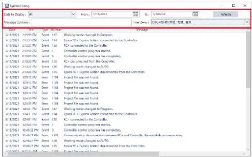
- System History
Indicates all histories, including events, errors, and warnings.
Tap the error number in the [Number] field to check the details of the error and countermeasure.
Set the following to change the period of time to show.
- 3D View preference
Setting for 3D View. The setting in here is associated with each individual controller. If you connect to another controller, set it again.

To reset to default value, tap
| Item Description | |
| General | Change setting of display format for all 3D Views.- GridShow grid lines on the ground surface.- ToolIndicate the robot arm tip arrow at the tool position specified in the hand settings.Tool Offset- World DirectionShow the world direction guide arrows on the ground surface.- Projection type |
| Program edit | Setting display style of the 3D view which is displayed when you tap thebutton on the screen.- Point- Pallet |
| 3D View display setting | Setting for coordinate value displayed in the 3D view screen.- Coordinates displayDisplays joint angle value of current position for World coordinate system.- Each axis angle displayDisplays coordinate value(J1 to J6) of current position for World coordinate system in slider bar. |
| Open CAD | Open CAD file (STEP/IGES) for Hand tool. You can adjust displaying position of the CAD. After setting all, tapto save the change.- CAD file path (STEP/IGES)- Scale unitSpecify the unit used in CAD file.- Mounting positionSpecify the position and orientation to display the CAD with the relative value from robot arm tip. |
- 6-axis robot environment setting
You can configure the environment settings of 6-axis robot. The settings in here are associated with each individual robot. You have to set it again when you connect to another robot.

To reset to default value, tap
| Item | Description |
| “Avoid Singular Postures” setting | You can configure “Avoid Singular Postures”.- Path prioritizedWhen the robot passes near a singularity while executing "Move linearly to", it maintains the linear trajectory and reduces the moving speed. When the robot is away from the singularity, it returns to the normal speed. If you choose this option, the robot tries to maintain the linearity of the path of the hand tool tip, but the robot arm may take unexpected posture. Be sure to test your program in rehearsal mode before running it at full speed. If you have changed [System Settings] - [Motion Range], it is recommended you set it to the default before the testing.- Speed prioritizedWhen the robot passes near a singularity while executing "Move linearly to", it tries to keep the speed constant of the hand tool tip, while reduces the linearity of the path of the hand tool tip. When the robot is away from the singularity, it returns to the normal trajectory. If you choose this option, the robot tries to maintain the linearity of the path of the hand tool tip, but the robot arm may take unexpected posture. Be sure to test your program in rehearsal mode before running it at full speed. If you have changed [System Settings] - [Motion Range], it is recommended you set it to the default before the testing.- Speed prioritizedWhen the robot passes near a singularity while executing "Move linearly to", it tries to keep the speed constant of the hand tool tip, while reduces the linearity of the path of the hand tool tip. When the robot is away from the singularity, it returns to the normal trajectory. If you choose this option, the robot maintains the speed of the hand tool tip, but the robot arm may perform unexpected motion. Be sure to test your program in rehearsal mode before running it at full speed. If you have changed [System Settings] - [Motion Range], it is recommended you set it to the default before the testing.- No settingWhen the robot approaches a singularity, it does not change the moving speed or the trajectory. If you choose this option, the robot maintains the speed of the hand tool tip, but the robot arm may perform unexpected motion. Be sure to test your program in rehearsal mode before running it at full speed. If you have changed [System Settings] - [Motion Range], it is recommended you set it to the default before the testing.- No settingWhen the robot approaches a singularity, it does not change the moving speed or the trajectory. |
| 6-axis robot basic posture | You can set the basic posture of the 6-axis robot. On the navigation screen, tap thebutton to return the robot to the basic posture set here.Jog Mode (Easy, Joint, World, Tool)Keep the default settings or enter the deg value of J1 to J6 if necessary. You can also set the current posture as the basic posture by tapping thebutton.After setting all, tapto save the change. |
Closing the Software
When you close the software, tap the
Operating Robot
Main Monitor
Manual Motion
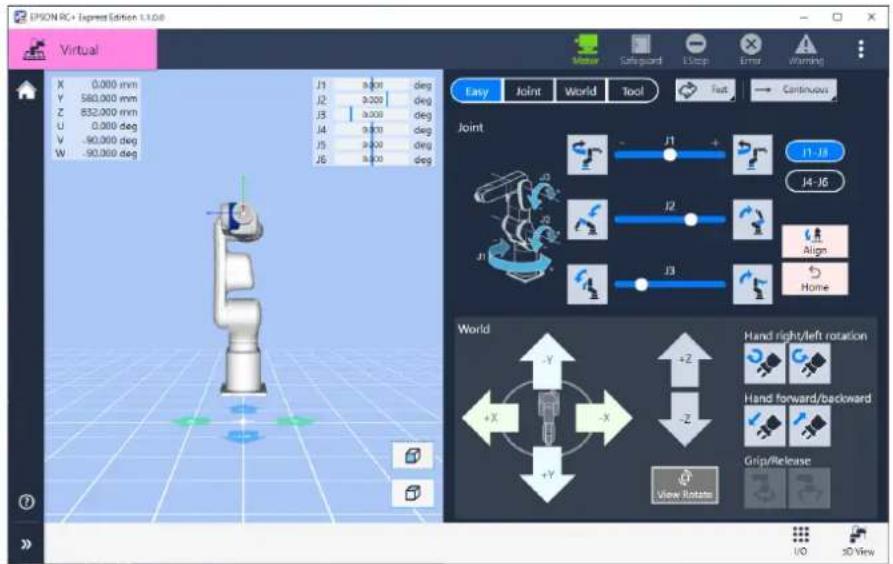
At Manual Motion, you can operate the robot with the graphical jog panel viewing 3D View.
3D view
Shows the current position and posture of the robot as 3D model.
- Tap
, button to change point of the view. - Pinch in or out to zoom in or out.
- The current coordinate values of the robot Jog panel are displayed as numerical values and slide bars. Operates the robot.
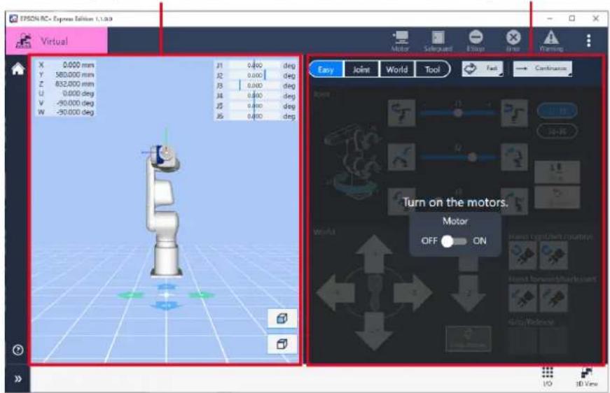
To display Manual Motion, tap Home - [Manual Motion].
![SPION RC - Express Edition 1. Ltd Virtual Robot Model : T3-4015 Connection : Virtual Control device : PC Settings Manual Motion To Program Protect mode Disconnect Language Loaded program Program not loaded Load a program or create a new program. All programs Name and description Create Import Update date and time Push [Create] to create a new program.](/content/2026/05/821542/images/8c0b3e7a76931435de7832bab197b739fdfc988c66cc2524d645545e20cd06ec.jpg)
Motor
Before operating the robot, tap to motor "On". When motor is "ON", you can operate the robot.

3D View
You can view the current position and posture of the robot.
Coordinate values
The coordinate values of the current posture in the World coordinate system are displayed numerically.
Joint value
The joint angle values (J1 to J6) of the current posture are displayed as numbers and the slide-bar-like indicators.
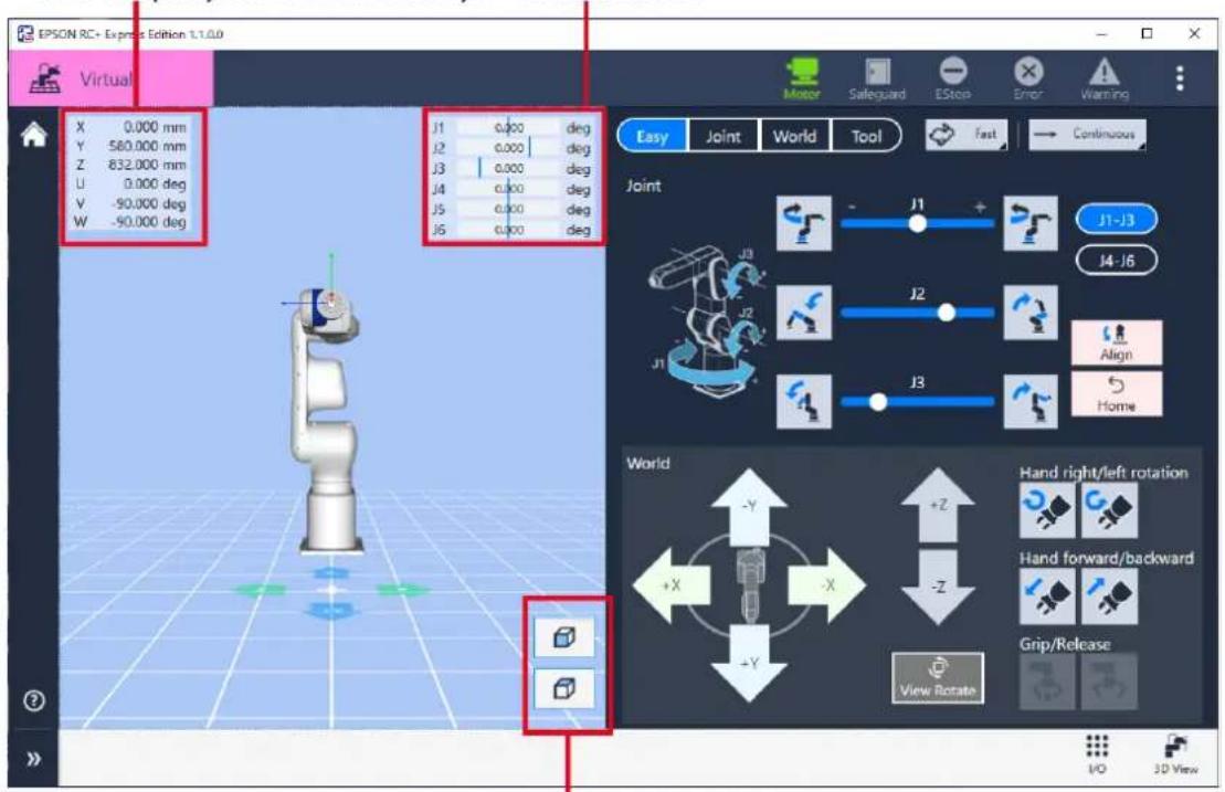
Point of view
Tap the
Jog Mode (Easy, Joint, World, Tool)
Select one of the following modes, depending on what type of control you want:

Below functions are common in all modes.
| Icon | Description |
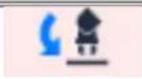 | Align the robot’s hand to the specified direction.Tap and select the direction to align. |
 | Returns the robot to the basic posture set in the [6-axis robot environment settings].Status Bar |
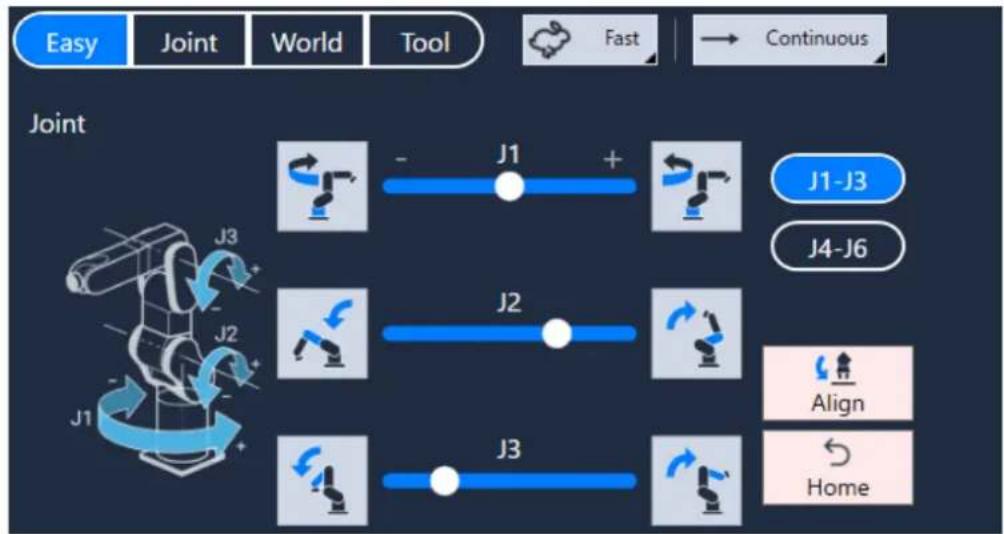
·Easy
Easy mode allows you to operate a robot in a single screen, without switching between Joint, World, Tool.
It is recommended to beginners.
[Joint] section is assumed to be used for rough positioning.
Select the group of joints you want to rotate from the following:
- J1-J3: Group to rotate a joint of J1/J2/J3.
- J4-J6: Group to rotate a joint of J4/J5/J6.
Tap or hold down the button of the direction of the joint you want to rotate. Where joints J1-J6 are located is shown in the illustration to the left.
flowchart
graph LR
    A[" "] --> B["J1"]
    B --> C["+"]
    C --> D["J1-J3"]
    D --> E["J4-J6"]
    E --> F["J2"]
    F --> G["Align"]
    G --> H["Home"]

When connecting to a virtual robot, you can also rotate a joint by dragging a slide control:

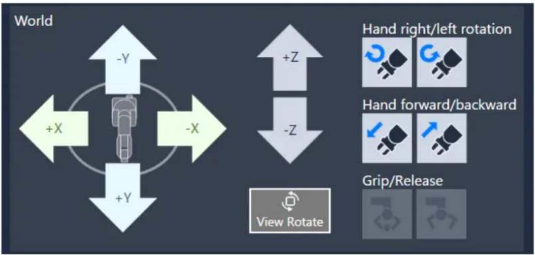
In [World] section, buttons for accurate positioning are placed.
X, Y, Z buttons are to control the hand tool tip in the world coordinate system.
flowchart
graph TD
    A["World"] --> B["Hand right/left rotation"]
    A --> C["Hand forward/backward"]
    A --> D["Grip/Release"]
    B --> E["+X"]
    C --> F["-X"]
    D --> G["+Y"]
    H["View Rotate"] --> I["-Z"]
    J["-Y"] --> K["Robot with hand icon"]
    L["-X"] --> M["Robot with hand icon"]
Hand tool buttons are assumed to be used for final approach to the destination. See the table below for their meanings.
| Icon | Description | |
 | Rotates the hand right and left. | |
 | Moves the hand forward and backward. | |
- Joint
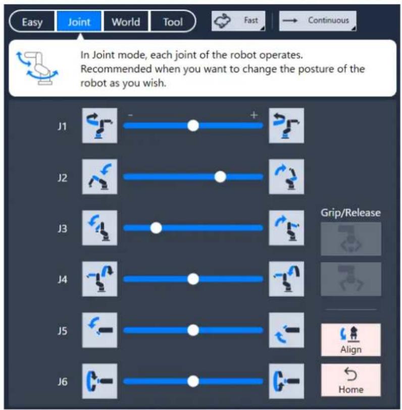
Joint mode is to operate a robot by controlling joint angles. Useful for rough and rapid positioning.
When you want to rotate a joint (J1 \~ J6) of robot, tap or hold down the button of the direction of the joint you want to rotate.
The icon of each button indicates which arm link moves when pressed and its direction.

When connecting to a virtual robot, you can also rotate a joint by dragging a slide control:

- World
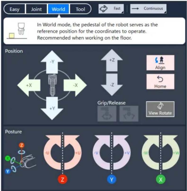
World mode is to operate a robot by controlling the position of the hand tool tip in the world coordinate system: X, Y, Z, U.
Useful for accurate positioning.
In [Position] section, buttons to move the hand tool tip in X, Y, or Z direction are placed, so tap or hold down the button of the direction you want to move the robot to.
In [Posture] section, buttons to rotate the hand around X, Y, or Z axis are placed, so tap or hold down the button of the desired direction of the axis you want to rotate the hand around.
flowchart
graph TD
    A["Position"] --> B["+X"]
    A --> C["-X"]
    A --> D["+Y"]
    E["Grip/Release"] --> F["+Z"]
    E --> G["-Z"]
    H["Posture"] --> I["-U"]
    H --> J["+U"]
    H --> K["-V"]
    H --> L["+V"]
    H --> M["-W"]
    H --> N["+W"]

Orientation of the jog buttons (X, Y, Z) can be rotated to be aligned with the guidance arrows in the 3D view.
Tap to open the dialog to rotate it.
• Tool
Tool mode is to operate the robot referencing the coordinate frame of which origin is fixed at the hand tool tip (referred to as tool coordinate system - Tool X, Tool Y, and Tool Z).
It is useful for approaching/working against an inclined surface.
In [Posture] section, buttons to rotate the hand around Tool X or Tool Y axis are placed, so tap or hold down the button of the direction of the axis you want to rotate the hand around.
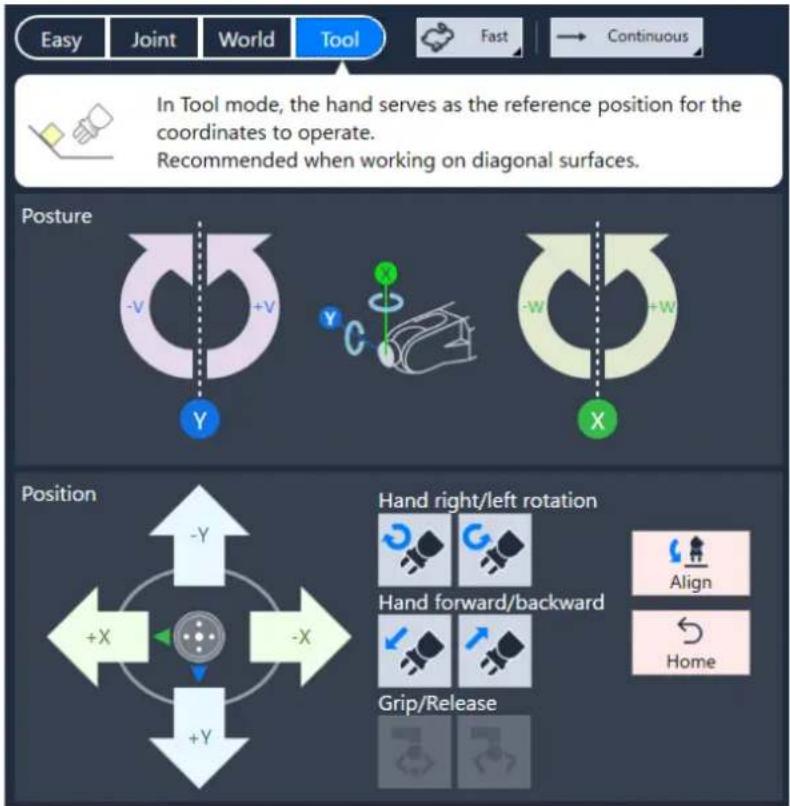
In [position] section, buttons to move the hand tool tip is placed.
Tap or hold down the button of the direction of the joint you want to rotate.
In [Posture] section, buttons to rotate the hand around X, Y, or Z axis are placed, so tap or hold down the button of the desired direction of the axis you want to rotate the hand around.
| Icon | Description | ||
 | Rotates the hand right and left. | ||
 | Moves the hand forward and backward. | ||
Jog Speed & Jog Distance
Setting Jog Speed & Jog Distance.
Jog Speed
Tap to select robot arm moving speed.
The icon varies depending on the speed you have selected.
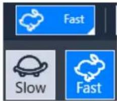
Following shows speed and acceleration/deceleration of 6-axis robot.
| Speed | Jog mode | Speed | Acceleration | Deceleration |
| Low | Continuous World, Tool, XYZ | 10 mm/sec | 200 mm/sec2 | 400 mm/sec2 |
| Continuous World, Tool, UVW | 2 deg/sec | 20 deg/sec2 | 40 deg/sec2 | |
| Continuous Joint | *1 | 20 deg/sec2 | 40 deg/sec2 | |
| Jog Distance Minimum, Short, Middle, Long, Custom | 1/5 of high speed | Default of Accel*2 | Default of Accel*2 | |
| High | Continuous World, Tool, XYZ | *1 | 200 mm/sec2 | 400 mm/sec2 |
| Continuous World, Tool, UVW | 15 deg/sec | 20 deg/sec2 | 40 deg/sec2 | |
| Continuous Joint | *1 | 20 deg/sec2 | 40 deg/sec2 | |
| Jog Distance Minimum, Short, Middle, Long, Custom | Default of Speed*2 | Default of Accel*2 | Default of Accel*2 |
*1 Speed of Continuous Joint and High speed Continuous XYZ varies depending on the robot model.
*2 Default values varies depending on the robot model. Refer to the specification table of your robot model.
Jog Distance
Tap to select robot arm moving step.
The icon varies depending on the width you have selected.
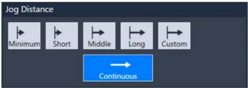
- Move with a certain width
Select the jog distance from "Minimum", "Short", "Middle", or "Long", and tap the
If you want to repeat the movement automatically, hold
The relationship between the selected distance and the amount of movement is as follows.
| Jog Distance Minimum Short | Middle Long | |||
| Linear movement (mm) / Rotational movement (degree) | 0.01 | 0.1 | 1.0 | 10.0 |
- Move continuously
Select "Continuous". The arm continues to move as long as the
- Specify custom movement distance
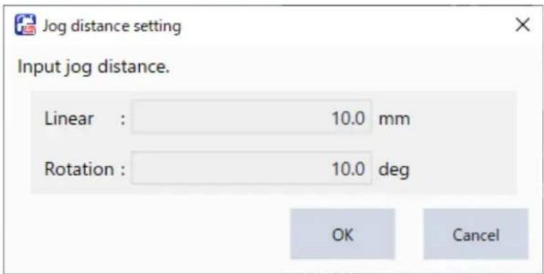
Select "Custom" to set moving distance and rotation as you like.
Their valid ranges are from "0.001" to "10.0".
Arm Posture
Shows the arm posture.

For motion commands in your program, specify the same arm posture as you taught whenever possible.
Otherwise the arm may follow an unexpected path and could damage peripherals.
Arm Posture
Following shows kinds of arm posture.
- Hand: Hand posture
Right (righty posture) / Left (lefty posture)
- Elbow: Elbows posture
Above (above elbow posture) / Below (Below elbow posture)
“Above” if J5 is on the straight line of J3, “Below” if J5 is under the straight line of J3.
| Righty hand orientation (Arm #1) | Lefty hand orientation (Arm #1) | ||||||||
| NoFlip wrist orientation | Flip wrist orientation | ||||||||
| Above elbow orientation | 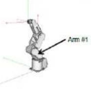 | 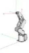 | Above elbow orientation | 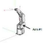 | 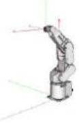 | ||||
| Below elbow orientation | 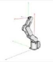 | 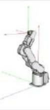 | Below elbow orientation | 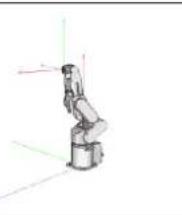 | 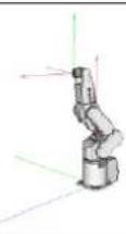 | ||||
• Wrist: Wrist posture
NoFlip (noflip wrist posture) / Flip (flip wrist posture)
"Flip" if J5 pulse is positive, "NoFlip" if J5 pulse is negative.
| NoFlip wrist orientation | Flip wrist orientation | |
| Above elbow orientation | 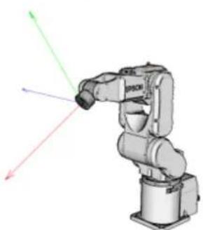 | 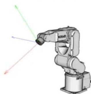 |
| Below elbow orientation | 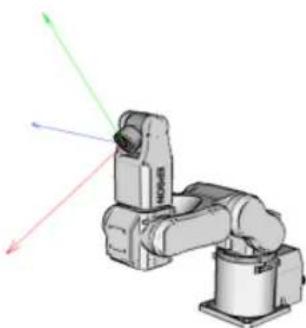 | 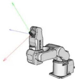 |
• J1Flag, J4Flag, J6Flag: Posture flag of each axis.
At some points in the work envelope, the 6-axis robot can have the same position and posture even if J4 or J6 is rotated 360 degrees.
To distinguish these points, the J4Flag and J6Flag point attributes are provided.
0/1
"0" if J1, J4, J6 degree is in certain range, "1" otherwise.
[J1]
"0" when -90°<J1 angle ≤270°, "1" otherwise (-270 to -90, 270 to 450).
For 6-axis robot, it is always "0" because its J1 can only rotate from -170 to 170.
[J4]
"0" when -180^ ≤ J4 angle ≤ 180^ , "1" otherwise ( -200^ to -180^ , 180^ to 200^ ). [J6]
"0" when -180°≤ J6 angle ≤180°, "1" otherwise (-360° to -180°, 180° to 360°).
For the details of Posture flag, see the following.
EPSON RC+ User's Guide
Singularity
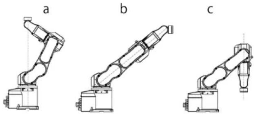
Singularity is the posture at the boundary where the arm posture switches to the other.
Robot is in singular postures
•a: Hand singularity. The boundary where Right hand posture and Left hand posture switch
•b: Elbow singularity. The boundary where Above elbow posture and Below elbow posture switch
•c: Wrist singularity. The boundary where NoFlip wrist posture and Flip wrist posture switch
Operating Robot
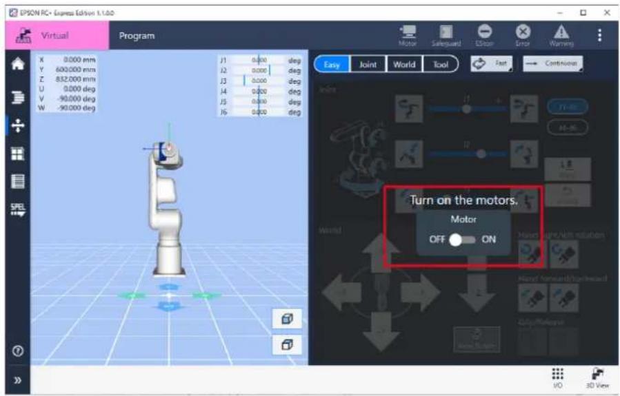
How to operate the robot and check the motion on 3D View :
Operation procedure
1. Turn the motor "ON".
Enables the Jog panel to operate the robot.
2. Select Jog Mode (Easy, Joint, World, Tool).
In this example, select Joint. Jog Mode (Easy, Joint, World, Tool)
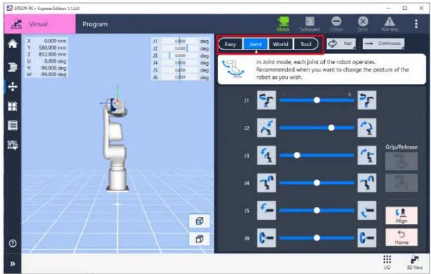
3. Tap the icon on the Jog panel or hold it down or drag

and check the robot motion.
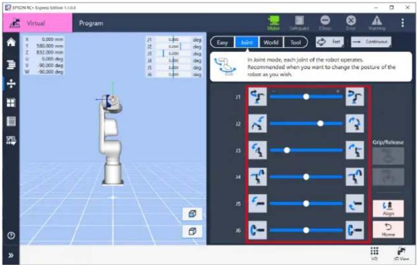

- Orientation of the jog buttons (X, Y) can be rotated to be aligned with the guidance arrows in the 3D view.
Tap to open the dialog to rotate it.
- If you want to change the speed of motion, change settings of Jog Speed and Jog Distance.
Jog Speed & Jog Distance
- If you want to operate with hand tool, set up the hand tool.
General
Programming
Program Screen Layout
Program Screen
On this screen, use commands to create a program and check the motion.
Command area
Shows available commands for program. You drug and drop a command to editing area to add it to your program.
Editing area
Shows your program. You view and edit you program in here.
Detail setting area
You change detailed settings of a selected command in the Editing area.
![EPSON RC + Express 01.13.02 Virtual Program Basic Move To Pick from Place at Container Motor Motor On Motor Off Hand Grip Release Pallet Move Forward Event Log Start Paste Collapse View Stop Settings Motor On Low Move To Home Position Loop Initiate Pick from Parts Reeiling pos Place at Target position Motor On [Motor On] turns on the motors to get the robot ready to operate. Power Select power mode High Low 60 3D View](/content/2026/05/821542/images/ff87985487e8d6855b3d8dfcf29dfdd2eee7b8c21664ee025face40ce02f8d00.jpg)
Event log
Shows error messages or debug log messages printed by the program.
Operation control button Start/stop the operation.
I/O
You can check and change the I/O input/output setting. 3D View Useful when in virtual mode.
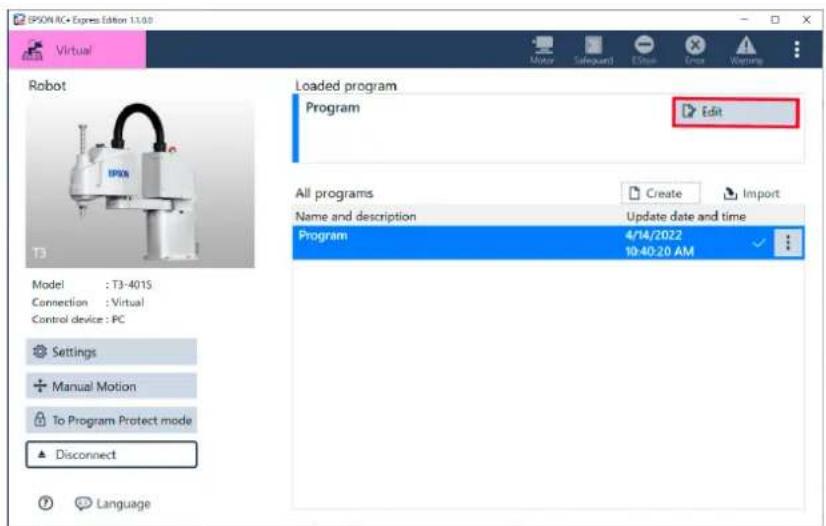
In Home screen, tap [Edit] to display the program screen.
Setting a Program Operation
This window is to configure the default values of speed of motion etc. according to path type. The default values set in here take effect on all the "Move to", "Move linearly to" commands in your program.
![Settings Configure settings related to operation. Move to Move linearly to Waypoint LIM Speed [%] Move to 1 5 20 > >> >> Slow Mid Fast 1 1 100 Accel [%] 1 5 20 > >> >> Slow Mid Fast 1 1 100 Restore defaults Speed [mm/sec] Move linearly to 120 200 400 > >> >> Slow Mid Fast 1 1 100 2000 OK Cancel](/content/2026/05/821542/images/02ace4cd48fc47307dc851a8d3a2718403bbe8fd2eace6d47d3dc0311d912a9b.jpg)
To open this window, tap [Settings] above the Editing area.
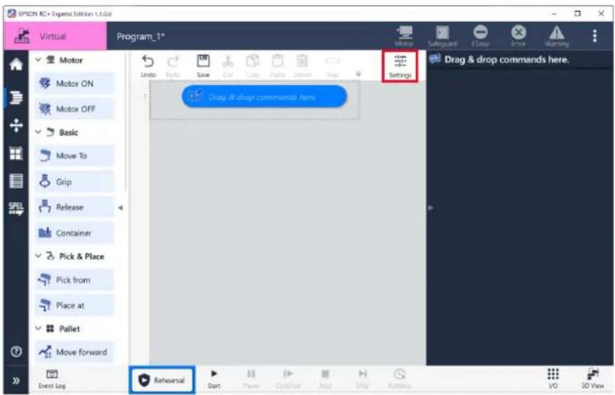
Operation procedure
1. Select a path type from [Move to] or [Move linearly to].
When you tap any one of the path types, it jump-scrolls to the selected section.
![Settings Configure settings related to operation. Move to Move linearly to Waypoint LJM Speed [%] 1 5 20 > >> >> Slow Mid Fast 100 Accel [%] 1 5 20 > >> >> Slow Mid Fast 100 Restore defaults Speed [mm/sec] 120 200 400 > >> >> Slow Mid Fast 1 2 2000 OK Cancel](/content/2026/05/821542/images/23369f65e1e4bf42eb6cd3cb988cd6da9b64f17f4ac79f968b2c94349113122c.jpg)
2. Move the knobs to change the default values of "Speed" and "Accel".
![Settings Configure settings related to operation. Move to Move linearly to Waypoint LJM Speed [%] Move to 1 5 20 Slow >> >> Fast 100 Accel [%] 1 5 20 Slow >> >> Fast Restore defaults 100 Speed [mm/sec] Move linearly to 120 200 400 Slow >> >> Fast 1 2000 OK Cancel](/content/2026/05/821542/images/2fb205330268885ea2ac29c79903c4ddae11773311631d4fb361d934d6ceb3b4.jpg)

To reset the values to the initial defaults, tap
3. Set the waypoint.
Waypoint is for Pick from / Place at command.
When approaching to the destination and departing from there by those commands, the robot goes through the waypoint specified here.
![Settings Configure settings related to operation. Move to Move linearly to Waypoint LJM Waypoint setting Set the position of the waypoint/evacuation point when the Pick/Place command is operated. It goes through or evacuates a position separated by the specified distance when approaching the destination. 100.000 [mm] Restore defaults LJM Least Joint Motion setting (LJM) Enable/Disable the function (LJM) that minimizes the amount of angle change of each joint during motion. Restore defaults Enable LJM. OK Cancel](/content/2026/05/821542/images/fd0377181e6761a507581453aa53a141f5287db26c6048f15972893b14199acf.jpg)

The default value of waypoint is 100.00[mm].
4. Set [LJM].
If you select "Enable LJM" from the pull down menu, robot moves so that the posture changes the least from the posture before the movement.
If you select "Disable LJM", robot moves with keeping the posture taught.
![Settings Configure settings related to operation. Move to Move linearly to Waypoint LJM Waypoint setting Set the position of the waypoint/evacuation point when the Pick/Place command is operated. It goes through or evacuates a position separated by the specified distance when approaching the destination. 100.000 [mm] Restore defaults LJM Least Joint Motion setting (LJM) Enable/Disable the function (LJM) that minimizes the amount of angle change of each joint during motion. Restore defaults Enable LJM. Enable LJM. Disable LJM. OK Cancel](/content/2026/05/821542/images/8e1f3fefbe9e39696c69b9cbecfda5068ab7ff02b94e7399d1fe3b7616ba105a.jpg)
Creating/Editing/Managing a Program
Creating a Program
Creating a Program Using a Template
For creating a program for very common use cases easily, some program templates are provided.
The procedure to create a program using a template is described below.
Operation procedure
1. Tap [Create].
![EPSON BC + Express Edition 1.1.0.0 Virtual Robot Model : T3-401S Connection : Virtual Control device : PC Settings Manual Motion To Program Protect mode Disconnect Language Loaded program Program not loaded Load a program or create a new program All programs Name and description Create Import Update date and time Push [Create] to create a new program](/content/2026/05/821542/images/193dabd6e5c659c3810e84c817f2eaecbda8086abbea29892747eef970da8113.jpg)
2. Select a template from the list.


Templates with mark utilize RC+ Project Link.
You need to activate "EPSON RC+ Express Advanced option" before you can use them without limitations.
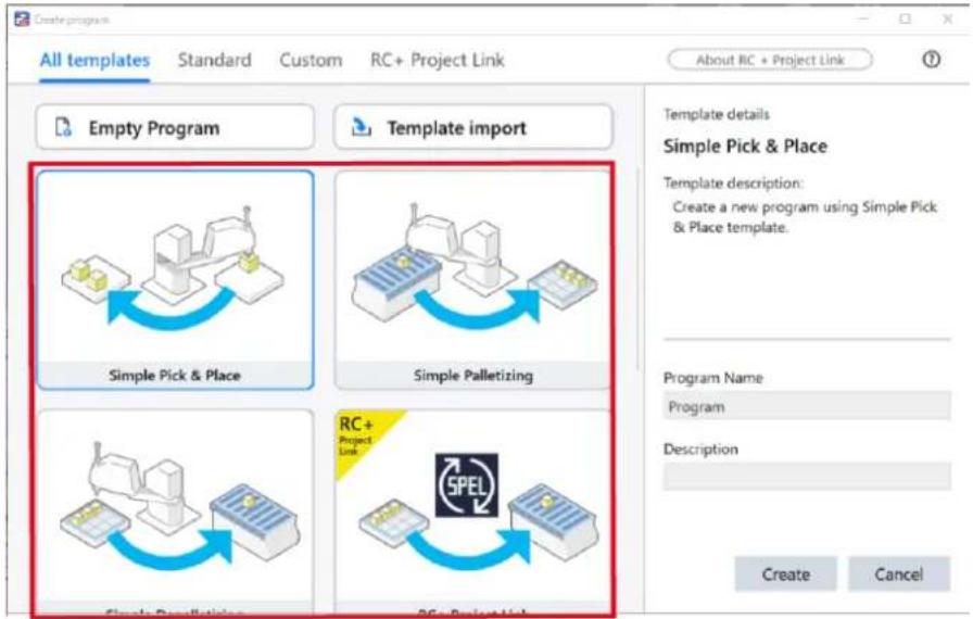
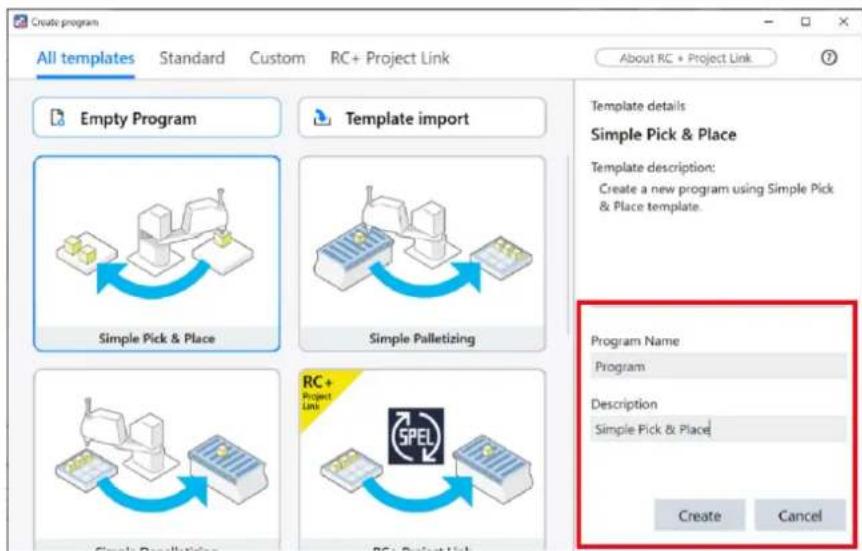
3. Enter "Program Name" and "Description", and then tap button.
Enter the program name using up to 24 single-byte alphanumeric characters. As an example, the followings are entered.
Program Name: Program Description: Simple Pick & Place
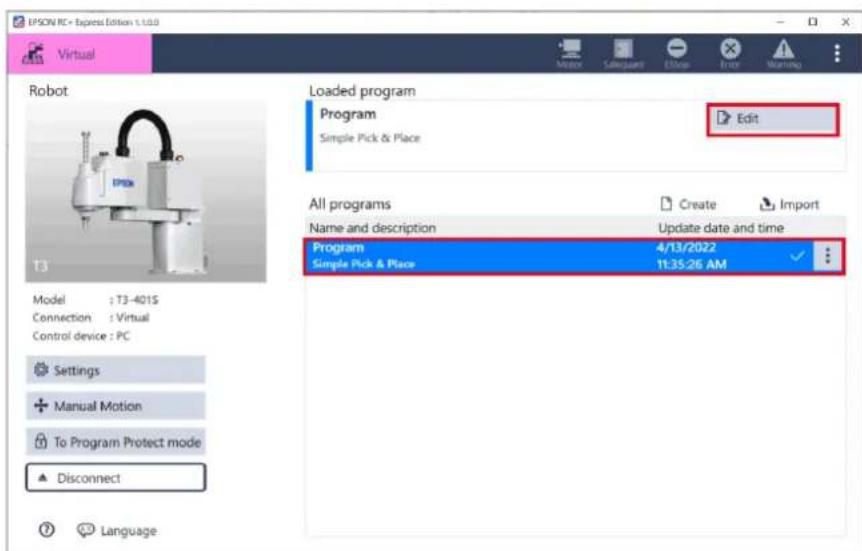
Now, you have created a program from the template. Tap [Edit] to edit the details of the program to realize your concrete application.
Command Function List:
Command Operation List
Program Examples (Tutorial)
Beginning with an Empty Program
If you do not find any available template useful for your purpose, create an empty program to begin with.
The procedure to create an empty program is described below.
Operation procedure
1. Tap [Create].
![EPSON RC Express Edition 1.0.0 Virtual Robot Loaded program Program not loaded Load a program or create a new program. All programs Name and description Update date and time Settings Manual Motion To Program Protect mode Disconnect Language Push [Create] to create a new program.](/content/2026/05/821542/images/c7d1c050f8349cc0c12ccaf6f9c60b219ea53e8f30f33f4a5ae7aa60afdea246.jpg)
2. When following screen is displayed, select [Empty Program].
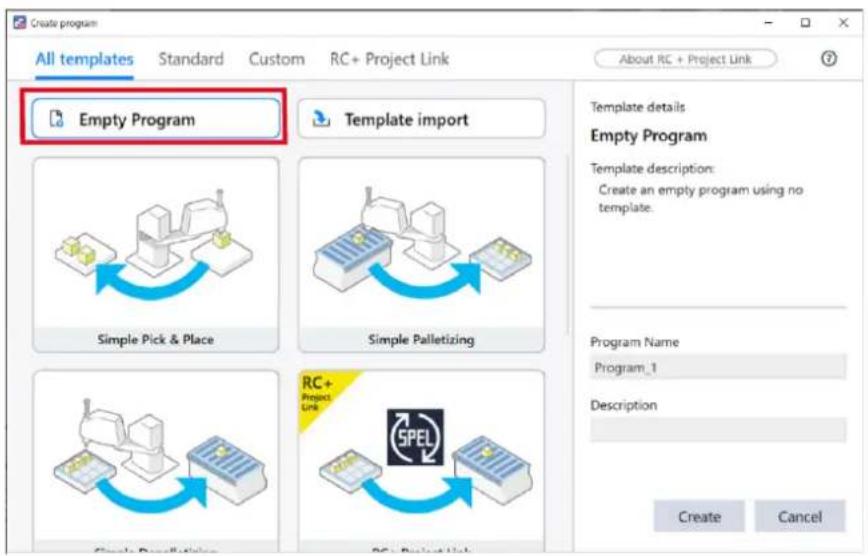
3. Enter "Program Name" and "Description", and then tap the button.
Enter the program name using up to 24 single-byte alphanumeric characters.
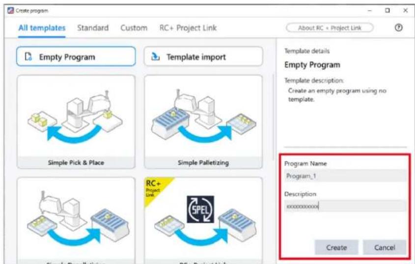
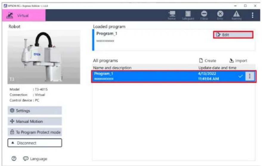
Now, you have created an empty program. Tap [Edit] and begin programming from scratch.
Command Function List:
Command Operation List
Program Examples (Tutorial)
Executing a Program
Executing a Program to Check for Problems
Once the program is complete, execute it in the [Rehearsal] or [Start] to check whether there is any problem. The rehearsal mode is a function to test programs safely.
It is recommended to use "rehearsal" when executing for the first time after creating a program.

To check safely using [Start]:
When checking the command operation separately, add to pause.

(break point) to the point
When clearing the break point, pause a program and tap


If you tap [Rehearsal] or [Start], the program you have created is send to the Robot (Controller).
Make sure that the communication cable is connected correctly.
If the connection is lost, the program may be damaged.
This page describes a procedure of checking the motion using [Rehearsal].
Operation procedure
1. Tap the |Rehearsal|.
![1PSON RC + Express Edition 1.1.08 Virtual PickandPlace* Pick and Place (between 2 points) Motor ON Motor OFF Basic Move To Grip Release Container Pick & Place Pick from Place at Pallet Move forward Event Log Move To (Move to) moves the robot to the destination. Motion Select shape of motion. Joint Linear Jump Specify the height of Jump motion. Height Use the [Settings] value [mm] Arch Gate motion Destination Select the reference position of the destination. Point point Point Specify the name of the destination. Point1 Set the position of the destinations. You can Rehearsal Start End Start End OK 3D View](/content/2026/05/821542/images/3185ac550033a88e809ae6520015f6154394053b9254f1cdd0e09039cfed2e5c.jpg)
Functions of the operation buttons are as follows:
| Icon Usage | |
 | Tap to start debugging.You can set a speed limitation at the start. |
 | Tap to pause when a program is running. |
 | Tap to resume a program when the program is in break or pause. |
 | Tap to stop. |
 | Tap to execute commands one by one from a break point. |
 | It is forced to be restricted to low power mode and the command is executed only while thebutton is pressed. |
 | Tap to have the robot follow the previous motion and return to its original posture. |

- When connecting to a virtual robot, tap <3D View> button to open 3D View window to visually check the robot motion. The usage of 3D View is as follows.
- : Toggles the ghost arm view for the point preview. Note that the preview posture and the actual posture taken by the robot arm during program execution may differ. Be sure to use the rehearsal mode to check the actual motion.
![VISION RE: Express Button 1.5.0 Virtual Program_1* xxxxxxxxxxxx Motor ON Motor OFF Basic Move To Grip Release Container Pick & Place Pick from Place at Pallet Move forward Event Log Rehearsal Start Save Cut Copy Delete Skip Settings Place at [Place at] is a combined command that Start the robot moves to the destination and Dot Time: 00:00:00.0000 Clear ocation of the Destination. 10:000 [mm] 10:000 [mm] 10:000 [deg] 10:000 [mm] 10:000 [mm] 10:000 [mm] 10:000 [mm] 10:000 [mm] 10:000 [mm] 10:000 [mm] 10:000 [mm] 10:000 [mm] 10:000 [mm] 10:000 [mm] 10:000 [mm]](/content/2026/05/821542/images/616dac61f0b2fdf204318b722f419c86cdcd2ebf8ca0bc166198dd3144509ab3.jpg)
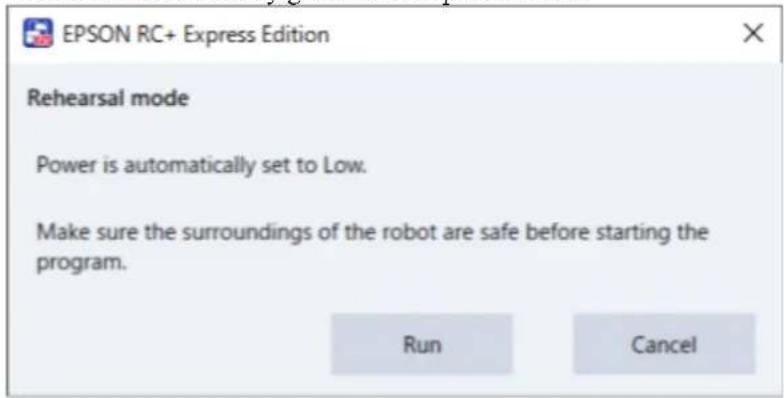
2. When a confirmation dialog appears, confirm the safety of your surroundings, and then, tap the button.
The motor automatically goes into low power mode.
3. Press and hold the button.
Release the
![EPSON RC + Express Edition 1.1.08 Virtual PickandPlace Pick and Place (between 2 points) Motor ON Low Move To Point! Move To [Move to] moves the robot to the destination. Motion Select shape of motion. Specify the height of Jump motion. Height Use the [Settings] value [mm] Arch Gain motion Destination Select the reference position of the destination. Specify the name of the destination. Brakes have been applied / Movement is paused. Event Log 100% Reaction Stop Pause Close Stop Jump Balance UCI 3D Value](/content/2026/05/821542/images/0c7cf81c0fc574099aa65dad35981fe5e3152b84b20e33565fcd5854722347c4.jpg)

- When connecting to a virtual robot, the continuous running time of the program is limited to up to 1 hour.
- When a program is running, you cannot edit the program.
- When an error occurs while a program is running, the command that causes the problem blinks in red and
appears at the left side of it. Also, the Error flyout pops up under the Error icon.
Tap "Details" in the flyout to check the details and countermeasure.
Checking Event Log
Check Event Log for the details and the occurrence date and time of errors which occurred while a program was running.

Tap (Event Log) to display the event log.
Messages are displayed in black, errors in red, and warnings in blue.
![IPSON RC+ Express Edition 1.1.0.0 Virtual Program_1* Loop [Loop] repeats the commands placed inside it. Mode Select the continuation condition of the loop Count Condition Infinite Loop Count Specify the number of repetitions: 1 Add Exit If Add an Exit # command, that breaks the loop immediately. + Copy to Clipboard Clear Event Log Rehearsal Start Close Close Stop Stop Refresh UO 3D View](/content/2026/05/821542/images/637c392c3d30c7b7aa175f1a6ccbe9bf4f56b42d94205d82316f14ba8bc8f66a.jpg)
The types of Event Log icons are as follows.
| Icon Description | |
 | There is no event log. |
 | There is a new event log.Warning number and message are displayed. You can check manuals by tapping the warning number. |
 | There is an error event log.Error number and error message are displayed. You can check manuals by tapping the error number. |
Rollback
Rollback is a function to make the robot return to its original posture by reversing the same path as the previous motion.
This function is useful when a program stops due to a problem when the robot is working in a narrow space from where it is hard to exit by manual control.
To use this function, select "PC" in [Controller device change].
Controller Configuration

If a message that the robot's current position and the recorded position are far apart is displayed, the robot goes to the last recorded position by auto-generated path. Check the safety of the area around the robot before executing rollback.
Following procedure describes how to use this function when a program is stopped or in an error state.
Operation procedure
1. Before executing rollback, clear all the error state including EStop,
then tap the (Rollback) button.
![MPSON RC+ Engine Edition 1.0.0 Virtual Program_1 xxxxxxxxxxxx Motor Save Cut Copy Delete Stop Settings Motor ON Motor Off Basic Move To Grip Release Container Pick & Place Pick from Place at Pallet Move forward Event Log Rehearsal Start Continue Stop Stop Rollback Loop [Loop] reprimates the commands placed inside it Mode Select the continuation condition of the loop Count Condition Infinite Loop Count Specify the number of repetitions 1 + Add Exit If Add an Exit if command, that breaks the loop immediately. 1/0 3D View](/content/2026/05/821542/images/efb3c910fdaefcdbbd3a05d188618b035d26a625f22ee7695a582ff3da951a1d.jpg)
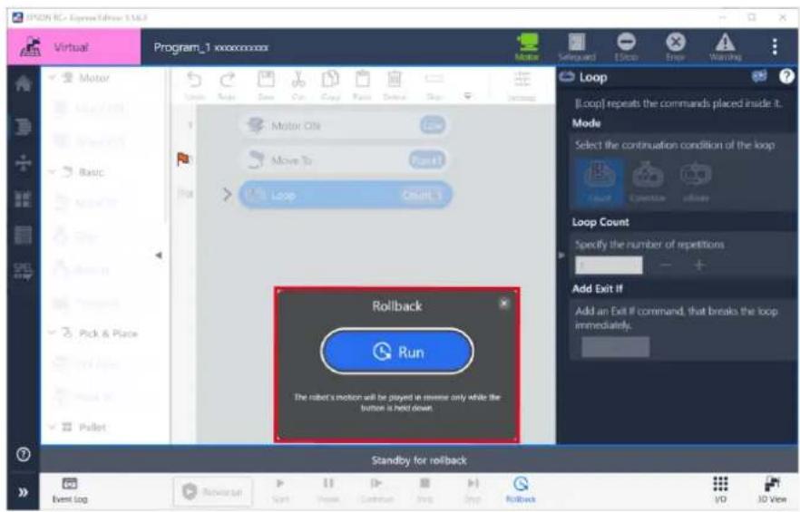
2. Press and hold the button to reverse the motion.
The action is reversed while the button is pressed.

When rollback fails, refer to the following:
Failed in Rollback
Editing a program
Command Operation List
Commands are operation instructions such as moving, gripping Hand, and turning the motor ON / OFF that is used in programming. This page describes how to make your program by manipulating those commands with the editing tool shown below.

natural_image
Row of simple document and edit icons including refresh, folder, scissors, and document (no text or symbols)For adding a command, refer to the following:
Adding a Command
Functions of the editing tools are described below.
| Icon Usage | |
 | Cancels the previous operation. Undo, Redo |
 | Cancels [Undo]. Undo, Redo |
 | Saves the edited program. Save |
 | Copies the selected command and then delete it. Cut and Paste |
 | Copies the selected command. Copy and Paste |
 | Inserts the previously copied command. Cut and Paste |
 | Deletes the selected command. Deleting a Command |
 | When a program is run, skips (not execute) the command. The skipped command is displayed in italics. Skipping a Command |
| [T048] | Operation buttons are hidden. When there are some buttons not displayed, tap the icon. |
 | You can set the default value of the speed and acceleration. Setting a Program Operation |
Adding a Command
Tap a command in Command area to add it to your program. After adding the command, drag and drop the command to move to any position.
You can also drug and drop a command from Command area to Editing area to add it to your program.

Commands can be added up to 999 lines.
![HPSON RC Express Edition 1.1.0.0 Virtual Program_1* xxxxxxxxxxxxx Motor Motor ON Motor OFF Basic Move To Grip Release Container Pick & Place Pick from Place at Pallet Move forward Event Log Rehearsal Start Save Cut Copy Paste Delete Skip Settings Loop [Loop] repeats the commands placed inside it Mode Select the continuation condition of the loop Count Condition Infinite Loop Count Specify the number of repetitions 3 Add Exit If Add an Exit if command, that breaks the loop immediately V/O 3D View](/content/2026/05/821542/images/3187b07fc32454ff312c13099cff0efc821a5a53d6fdace5303b98b4544ac376.jpg)
Undo, Redo
Tap (Undo) to cancel the previous operation.
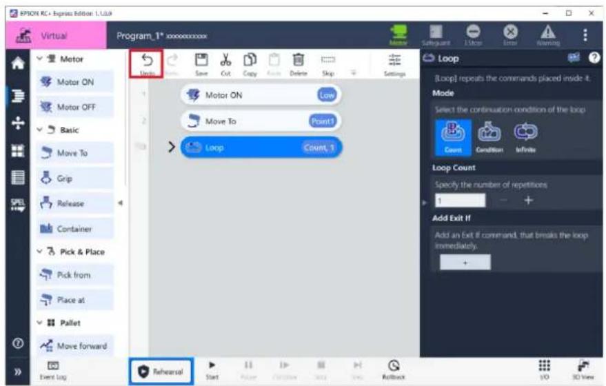
Tap (Redo) to cancel the undone previous Undo operation.
![IPION PC - Express Edition 1.100 Virtual Program_1* xxxxxxxxxx Loop [Loop] repeats the commands placed inside it. Mode Select the continuation condition of the loop Count Condition Infine Loop Count Specify the number of repetitions: 1 Add Exit If Add an Exit if command, that breaks the loop immediately Event Log Reversal Start Save Common Buy Stop Rollback EndUp Exit Error Warning Auto Auto ON Motor OFF Basic Move To Grip Release Container Pick & Place Pick from Place at Pallet Move forward Event Log](/content/2026/05/821542/images/b17e76621bc16b3909f2d3eaf3767db9f968c2c53ca2a1f9c2d913280707f0fe.jpg)
Save
Tap (Save) to save the edited program.
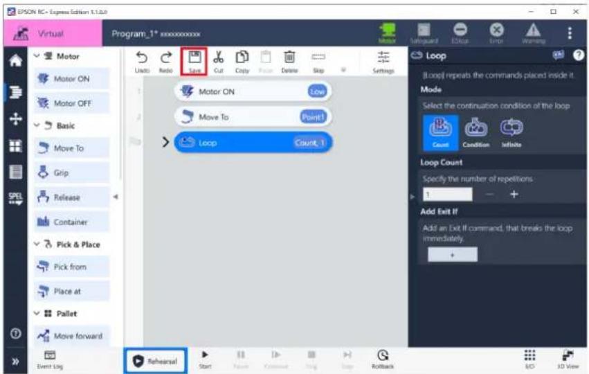
Copy and Paste
Operation procedure

1. Select a command to be copied and tap
(Copy).
The selected command is displayed in blue.
![EPSON RC Express Edition 1.0.4 Virtual Program_1* xxxxxxxxxx Loop [Loop] repeats the commands placed inside it. Mode Select the continuation condition of the loop Count Condition Infinite Loop Count Specify the number of repetitions: 3 Add Exit If Add an Exit if command, that breaks the loop immediately. Event Log Rehearsal Start Finish Finish Stop Rollback End Point Reset Save Cut Copy Delete Stop Settings Motor ON Motor OFF Basic Move To Grip Release Container Pick & Place Pick from Place at Pallet Move forward Event Log](/content/2026/05/821542/images/f931173a8b4d37801d90551f7a967be477a40d14e425b806b8079be8a56b4112.jpg)

2. Select the command which is at the position to insert and tap (Paste).
The command is inserted under the selected command.
![EPSON RC Express Edition 1.1.0 Virtual Program_1* Motor Save Cut Copy Paste Stop Settings Loop [Loop] repeats the commands placed inside it. Mode Select the continuation condition of the loop Count Condition Institute Loop Count Specify the number of repetitions: 1 Add Exit If Add an Exit If command, that breaks the loop immediately. Event Log Rehearsal Start Enter Calculate Text Step Feedback UO 3D View](/content/2026/05/821542/images/8332c7062f775f104325d9ae16133cc798874e41526f12a235ef3824195bbf1b.jpg)
Deleting a Command
Select a command to be deleted and tap (Delete).
![EPSON RC - Express Edition 1.1.0.0 Virtual Program_1* xxxxxxxxxxxx Motor Subo Resto Save Cut Copy Paste Delete Skip Settings Loop [Loop] repeats the commands placed inside it. Mode Select the continuation condition of the loop Count Condition Infinite Loop Count Specify the number of repetitions 1 Add Exit If Add an Exit If command, that breaks the loop immediately Rehearsal Start Name Continue Stop Stop Rollback Event Log 3D View](/content/2026/05/821542/images/880003bb993b7b5e51fa944b124037030cd06b9321d47c82b95e67a9fdbaa055.jpg)
Cut and Paste
Operation procedure
1. Select a command to be cut and tap do(Cut) .
![EPSON RC4 Express Edition 1.0.0.0 Virtual Program_1* 10000000000 Motor Auto Delete Save Cut Copy Paste Delete Stop Settings Loop [Loop] repeats the commands placed inside it. Mode Select the continuation condition of the loop Count Condition infinite Loop Count Specify the number of repetitions 1 Add Exit If Add an Exit If command, that breaks the loop immediately. Event Log Rehearsal Start Place Common Tools Stop Rollback I/O 3D View](/content/2026/05/821542/images/aa9f1fd1cf8bd7160c0fdc9eb8136951170ad1c722a5d6a63034bff7ca284090.jpg)

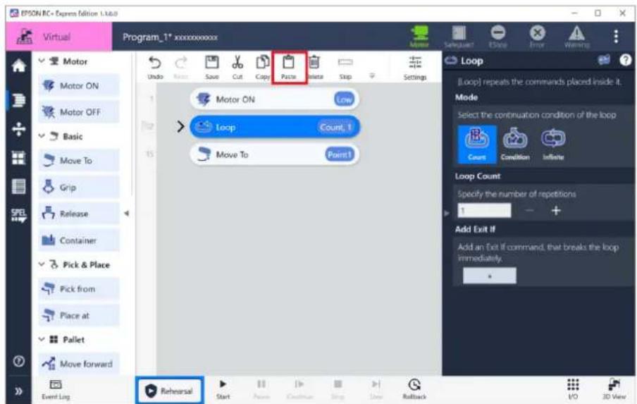
2. Select the command which is at the position to add and tap (Paste).
The command is inserted under the selected command.
Skipping a Command
Select a command to be skipped and tap (Skip).
![EPSON RC Express Edition 1.1.0.9 Virtual Program_1* xxxxxxxxxx Motor Setpoint Reset Error Warning Loop [Loop] repeats the commands placed inside it Mode Select the continuation condition of the loop Count Condition Infinite Loop Count Specify the number of repetitions 3 Add Exit If Add an Exit If command, that breaks the loop immediately. Event log Rehearsal Start Finish Outcome Stop Help Rollback End 3D View](/content/2026/05/821542/images/3106dec2e22a6168da19f0db7628afcbfc53c6a857f1396dcd4f3f83cf5609a7.jpg)

To undo the skip operation, tap ..... (Skip) again.
Managing a Program
Switching Loaded Program
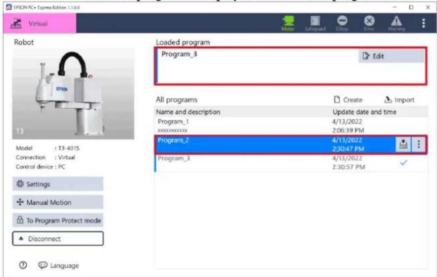
To switch loaded program to edit, select a program from all programs list to
switch and tap (Load).
The name of the loaded program is displayed in the loaded program field.
Changing Program Name and Description
This page describes how to change name and description of a program.
Operation procedure
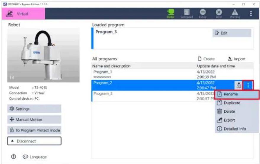
1. Select a program and tap - [Rename].
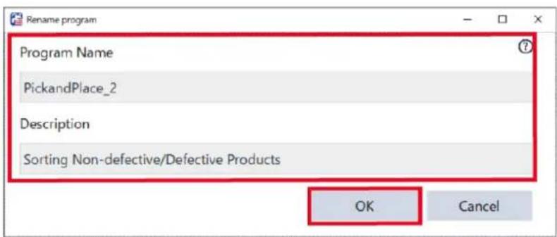
2. Change the name and description of the program and tap button.
Enter the program name using up to 24 single-byte alphanumeric characters.
Duplicating
This page describes how to duplicate a program.
Operation procedure
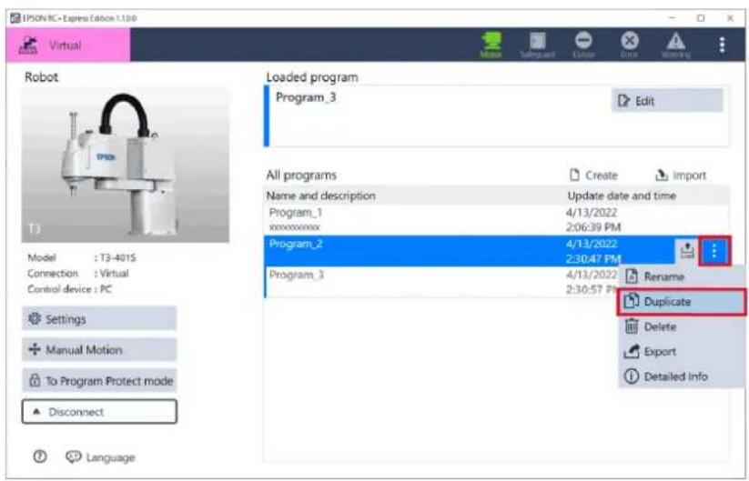
- Select the program to duplicate and tap - [Duplicate].
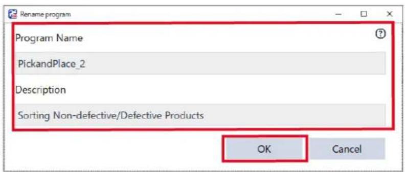
2. Change the name and description of the program and tap button.
Enter the program name using up to 24 single-byte alphanumeric characters.
Deleting
This page describes how to delete a program.
Operation procedure
- Select a program to delete and tap - [Delete].
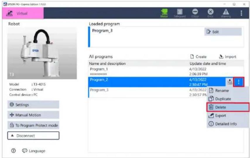
- Check the screen and tap the
button.
Functions of Command
About Command
Commands are operation instructions such as moving, gripping, and turning the motor ON / OFF that is used in programming.
This page describes common features of the commands.
For details of how to make your program using these commands, refer to the following:
Command Operation List
Badge
Indicates the simplified settings of the command.
It is displayed only for commands that have properties to be set.

Comment
You can add comment to a command for explanatory purpose. It is displayed right side of a command.
Comments do not affect the operation of the program.


For [Container] and [Comment] command, comment is displayed at the position of command name.

To add comment, select the command and tap input a comment.

of detailed settings then
![Move to Comment [Move to] moves the robot to the destination. Destination](/content/2026/05/821542/images/d1a30a23a087dbae69b49ab689a67df6688039455f6e389fc621592e115db226.jpg)

Length of comment can be up to 1024 letters. Comment can be multiple lines, but only first 2 lines are displayed next to the command.
Command help
Tap a command and tap to view the command's description.

![IPSON RC+ Express Edition 1.0.06 Virtual Program* Basic Move To Pick from Place at Container Motor Motor On Motor Off Hand Grip Release Pallet Move forward Event Log Start Next Close Stop Stop Joint (PTP motion) Moves from current point to destination without specifying route. The most efficient route type. Linear (CP motion) Moves from current point to destination by moving straight on the route. Jump Move To Select destination type Head point Pallet Specify the name of the destination. Point1 Specify the position of the destination. You can edit the coordinate values directly below or teach them using the Jog & Teach pane. X .... Y .... Z .... U .... Current orientation Jog & Teach [Go here] is to move the robot arm to the position specified above. V0 3D View](/content/2026/05/821542/images/349f59294a9a05df48bd498e25ef03c1607a363b60d2e8cb1a9e34d9abfa907d.jpg)

Swipe the top of the screen to move the manual position freely. This is convenient when you arrange the manual and software side by side. You can zoom in/out by dragging the outer frame of the screen.
Command Function List:
This page describes functions of the commands.
Motor
| Command Function | ||
 | Motor ON | Turn ON the motor to make the robot ready for operation. |
 | Motor OFF | Turn OFF the motor and stop the robot. |
Basic
| Command Function | ||
 | Move To | Move from current point to destination point. |
 | Move linearly to | Move linearly from current point to destination point. |
 | Grip | Grip a workpiece by the hand. |
 | Release | Release a workpiece holding by hand. |
 | Container | Combine multiple commands in it. |
Pick & Place
| Command Function | ||
 | Pick from | A series of operations from moving to the destination to gripping a workpiece. |
 | Place at | A series of operations from moving to the destination to releasing a workpiece. |
Pallet
| Command Function | ||
 | Move Forward | Move the current position of the specified pallet to next. |
 | Reset | Reset the current position of the specified pallet to the initial position (1). |
Logic
| Command Function | ||
| Output | Output signal to the specified output. | |
| Wait | Wait until the specified condition is satisfied, such as elapsed time or signal input. | |
| Loop | Repeat the operation a specified number of times, or while the specified condition is satisfied. | |
| If | Branch the program operation depending on whether the specified conditions are satisfied. | |
| Comment | Comment or explanation on the program. | |
| Quit | Stop the program immediately. | |
Dialog
| Command Function | ||
| Ask | Displays a question dialog. The user answers OK or Cancel. | |
| Notify | Displays a notification dialog. The user answers OK to close the dialog. | |
Log
| Command Function | ||
| Event Log | Print a message to Event Log. | |
SPEL+ Advanced
| Command Function | ||
| SPEL | SPEL+ Command | Execute a raw SPEL+ command. |
RC+
| Command Function | ||
| Variable | Assign a value to a variable defined in the imported RC+ project. | |
Motor ON
Turn ON the motor to make the robot ready for operation.
■ Detailed Settings
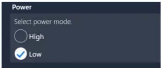
Power
The motor power of the robot. High or Low.

When Power is set to Low, operation speed is limited up to , 250 mm/sec.
Motor OFF
Turn OFF the motor and stop the robot.
Move To
This is a command for the robot to move (PTP operation) to the destination.
■Detailed Settings
Destination
Select the reference position of the destination.

Point
The robot moves to the point specified by Jog & Teach or by direct input.
Setting procedure
- Either tap the
button to specify the position, or tap [Destination coordinates], and directly enter the coordinates of the destination in X, Y, Z, U, V, and W. Operating Robot

You can also name a point (Up to 127 characters). The name that you give is displayed in 3D View. This is useful when checking the position that you taught visually.
2. Set the axis, posture flag, and LJM.
See below for the arm type and details. Arm Posture

You can move the robot to the begin position by tapping the
The robot moves to the current position of the selected pallet. Optionally, you can specify position offset.
Creating a New Pallet
Setting procedure
- Select a pallet to use from the pull down list.
Move to the creating pallet wizard to select the "Create a new pallet ..." from pull down list.
-
If necessary, specify position offset. Select "Offset" to open the offset input area and enter the offset values for X, Y, Z, U, V, and W directly. If you select "Offset," the offset input area will open.
-
Set LJM from the pull down list.
Arm Posture

Use the

file
The robot moves to the destination selected from the point file. Point File Viewer Screen
Setting procedure
-
Under Destination, tap |Point| - |Point file|.
-
Tap the
button.
you want to define a new point, go to the "Point File Viewer" screen.

-
From the list of point files, select the point to be specified as the destination.
-
Tap the
button.

You cannot edit the displayed point coordinates here. A point can be edited on the "Point File Viewer" screen.
- Set LJM from the pulldown menu.
Arm Posture
- Set the position offset with reference to the position of the point selected in 3.
This setting is optional. Select [Tool] or [World], and enter the position offset. Jog Mode (Easy, Joint, World, Tool)
Speed
Set the operation speed of the robot.
The default speed values in [Settings] are used for “Slow,” “Mid” and “Fast.”
Setting a Program Operation
Select "Custom" if you want to change "Speed" and "Accel" for that specific command.
Move linearly to
A command for the robot to move linearly (CP operation) to the destination.
■Detailed Settings
Destination
Select the reference position of the destination.
The robot moves to the point specified by Jog & Teach or by direct input.
Setting procedure
- Either tap the
button to specify the position, or tap |Destination coordinates|, and directly enter the coordinates of the destination in X, Y, Z, U, V, and W. Operating Robot

You can also name a point (Up to 127 characters).
The name that you give is displayed in 3D View. This is useful when checking the position that you taught visually.
2. Set the axis, posture flag, and LJM.
See below for the arm type and details.
Arm Posture

You can move the robot to the taught position by tapping the
The robot moves to the current position of the selected pallet. Optionally, you can specify position offset.
Creating a New Pallet
Setting procedure
- Select the pallet to use.
Move to the creating pallet wizard to select the “Create a new pallet ...” from pull down list.
- If necessary, specify position offset. Select "Offset" to open the offset input area and enter the offset values for X, Y, Z, U, V, and W.
If you select "Offset," the offset input area will open.
See below for the respective values.
Arm Posture
- Set LJM from the pull down list.
Operating Robot

Use the
file
The robot moves to the destination selected from the point file.
Point File Viewer Screen
Setting procedure
-
Under Destination, tap |Point| - |Point file|.
-
Tap the
button.
If you want to define a new point, go to the "Point File Viewer" screen.

-
From the list of point files, select the point to be specified as the destination.
-
Tap the
button.
You cannot edit the displayed point coordinates here. A point can be edited on the Point File Viewer screen.

- Set LJM from the pulldown menu.
Arm Posture
- Set the position offset with reference to the position of the point selected in 3.
This setting is optional.
Select [Tool] or [World], and enter the position offset.
Jog Mode (Easy, Joint, World, Tool)
Speed
Set the operation speed of the robot.
The default speed values in [Settings] are used for “Slow,” “Mid” and “Fast.”
Setting a Program Operation
Select "Custom" if you want to change "Speed" and "Accel" for that specific command.
Grip
If a hand is installed on the robot, the “Grip” operation can be performed.
To use this command, set up the Hand settings.
General
You can test Grip/Release operation with the buttons in the detailed setting area.
Tap the
Tap the
Release
If a hand is installed on the robot, the "Release" operation can be performed.
To use this command, set up the Hand settings.
General
You can test Grip/Release operation with the buttons in the detailed setting area.
Tap the
Tap the
Container
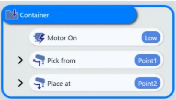
It is possible to combine multiple commands in a container.
Multiple commands can be combined into a single container. Commands in a container can be copied, deleted, or moved at once. It can also be collapsed to a single line to make the program look more compact.
Pick from
A combined command that moves the robot arm to the destination and grip a workpiece by hand.

■ Details of series of operations
| Command Label | Operation | |
| Move | Approach | Moves the robot up to the approach position by the PTP operation |
| Move linearly to | Destination position | Moves the robot linearly up to the destination position |
| Grip | - | Grips the workpiece |
| Wait | Time, 0.5 | Waits for 0.5 seconds |
| Move linearly to | Departure | Moves the robot linearly up to the departure position |
■ Settings of properties
Destination
Select the reference position of the destination.

The robot picks a workpiece from the point specified by Jog & Teach or by direct input.
Operating Robot

You can also name a point (Up to 127 characters).
The name that you give is displayed in 3D View. This is useful when checking the position that you taught.
The robot picks a workpiece from the current position of the selected pallet. Optionally, you can specify position offset. Choose "Create a new pallet ..." from the pull down list to create a new pallet. Creating a New Pallet

The robot picks a workpiece from the selected point in the point file. Choose the [Fixed point]-[Point file] and tap [Point file] button to select the point to be specified as the destination. Point File Viewer Screen
Waypoint/Evacuation point
Set the distance from the waypoint to the destination position that the robot passes along when the "Pick" command is executed. If you select "Use the [Settings] value," the waypoint/evacuation point set in [Settings] is applied. Setting a Program Operation
Decompose commands
If you tap the
Place at
A combined command that moves the robot arm to the destination and release a workpiece from hand.
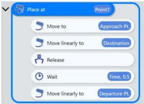
■ Details of series of operations
| Command Label | Operation | |
| Move | Approsach | Moves the robot up to the approach position by the PTP operation |
| Move linearly to Release | Destination | Moves the robot linearly up to the destination |
| - | Releases the workpiece | |
| Wait | Time, 0.5 | Waits for 0.5 seconds |
| Move linearly to | Departure Pt. | Moves the robot linearly up to the departure position |
■Detailed Settings
Destination
Select the reference position of the destination.
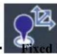
The robot releases a workpiece at the point specified by Jog & Teach or by direct input.
Operating Robot

You can also name a point (Up to 127 characters).
The name that you give is displayed in 3D View. This is useful when checking the position that you taught.
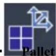
The robot release a workpiece at the current position of the selected pallet.
Optionally, you can specify position offset.
Choose "Create a new pallet ..." from the pull down list to create a new pallet.
Creating a New Pallet
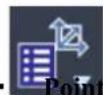
file
The robot release a workpiece at the selected point in the point file. Choose the [Fixed point]-[Point file] and tap [Point file] button to select the point to be specified as the destination.
Point File Viewer Screen
Waypoint/Evacuation point
Set the distance from the waypoint to the destination position that the robot passes along when the "Place" command is executed.
If you select "Use the [Settings] value," the waypoint/evacuation point set in [Settings] is applied.
Setting a Program Operation
Decompose commands
If you tap the
This is useful for making fine adjustments that cannot be made with the settings of the “Place at” command.
You cannot combine the decomposed commands to a single
Move Forward
A command to move forward the current position of the pallet to the next.
■ Detailed Settings
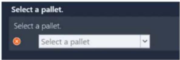
Select a pallet
Select a pallet from the pull down list, or choose "Create a new pallet ...".
Creating a New Pallet
Reset
A command to reset the current position of the pallet to the initial point (1).
■ Detailed Settings
![[Reset] resets the current position of the specified pallet. Select a pallet. Select a pallet. Select a pallet](/content/2026/05/821542/images/6722817345cb703895fa8cf2eba1e1b294631d7142f9fcd819e1a172b4b0c317.jpg)
Select a pallet
Select a pallet to reset to the initial point (1) from the pull down list, or choose "Create a new pallet ...".
Creating a New Pallet
Output
A command to output ON/OFF signal to the specified output target.
![[Output] outputs ON/OFF signal to the specified output bit. Output Target Specify output bit#. Unselected Signal Select ON or OFF signal. OFF](/content/2026/05/821542/images/ffee43d0c23321034e457e81cf594ede2205cc2db6d02681d5468f27890f5eac.jpg)
■ Detailed Settings
Output Target
Select an output bit from the pull down list.
I/O Functions

- It is possible to select category of outputs and show less as you like by using the filter. - Bits used by Remote I/O is not shown.
Signal
Select ON/OFF of the outputs.
Wait
Wait until the specified condition is satisfied, such as elapsed time or signal input. This is useful, for example, when the robot has to wait for the robot hand to properly grip the workpiece.
Detailed Settings
Wait Target
Specify what to wait.

The program pauses for the specified time duration (unit: seconds). Range of the wait time is 0.00 to 2147483.00 seconds (valid to two decimal places).

The program pauses until the specified condition is satisfied.

When multiple conditions are specified, they are always evaluated in order from the top to bottom. For example, when condition 1, 2, and 3 are specified, the pair of condition 1 and 2 is evaluated first. Then, its result and condition 3 are paired and evaluated. Its result is the total result of the evaluation. {(A and/or B) and/or C}
Steps to set conditions
1. Tap [+ Add Condition].
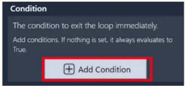
2. Tap the pull down and select the condition type.
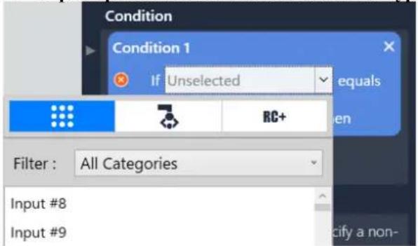

- Setting with (Input signal bits)
Select the number of Input bit and the state of Input bit like following.
"If (Input bits) equals (state: ON/OFF)"

- You can select category of Input and show less as you like by using the filter.
For the details of I/O types, refer to the following.
Setting for the I/O
- Input bits assigned to are not shown.

- Setting with (Hand)
Judged by whether the hand is gripping a workpiece. Select like following.
"If (Hand (Gripped / Released)) equals (True / False)"
- Setting with

(RC+)
This condition type appears only when an RC+ project is imported using RC+ Project Link.
Select the condition in the following format:
"If (Variable Label / Variable Name) equals (xx)"
Overview of RC+ Project Link
From the list of global variables defined in the imported RC+ Project, select the variable for which the condition is to be judged.
The valid format of the condition varies depending on the type of the selected variable.
| Variable type Option/Input limit | Operator when setting the condition | ||
| Boolean | 2 bytes, True/False | True/False | = |
| Byte | 2-byte integer, -128 to +127 | Only integers can be entered | =><><=◇ |
| Integer | 2-byte integer, -32768 to 32767 | ||
| Short | 2-byte integer, -32768 to 32767 | ||
| In32 | 4-byte integer,-2147483648~2147483647 | ||
| In64 | 8-byte integer,-9223372036854775808~9223372036854775807 | ||
| Long | 4-byte integer,-2147483648~2147483647 | ||
| Ubyte | Unsigned 2-byte integer, 0 to 255 | 0 or a greater integer can be entered | =><><=◇ |
| Ushort | Unsigned 2-byte integer, 0 to 65535 | ||
| UInt32 | Unsigned 4-byte integer, 0 to 4294967295 | ||
| UInt64 | Unsigned 8-byte integer,0~18446744073709551615 | ||
| Real | 4-byte real number, significant digits: 6 | Only numerical values can be entered | =><><=◇ |
| Double | 8-byte real number, significant digits: 14 | ||
| String | ASCII characters only, 255 characters max. | =◇ | |
3. Tap <+> button to add more conditions.
You can select an operator between conditions when there are more than two conditions.
And: True if both condition A and condition B are satisfied.
Or: True if condition A or condition B is satisfied.
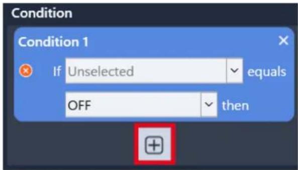
Timeout
If you select [Condition] as the Wait Target, you can specify its time out period. When 0 is specified:
No time out. Waits forever unless the specified conditions are satisfied.
When non-zero value is specified:
After the specified timeout period has elapsed, the program resumes regardless of whether the condition is satisfied or not.

For example, if you want the program to wait only 5 seconds for input #1 to turn ON, add Wait command and set it as follows:
- Select "Condition" as the wait target
- Specify "Input #1 equals ON" as the condition
- Set the timeout to 5.0
Then the program will wait at the command until input #1 turns ON, but will give up and restarts from the next command after 5 seconds.
Loop
A command to repeat the operation of a specified number of times or while the specified conditions are satisfied.
■ Detailed Settings
Loop
Select the type of the loop.
Repeat a specified number of times.

Repeat while the specified conditions are satisfied.

Repeat forever.
Loop Count
Tap +, - button to select the number of repetition (up to 32767).
Loop Condition
Tap [+ Add Condition] to add a new condition. Repeats the operation while the condition meets.
For the details of setting conditions, refer to the following:
If
Add Exit If
You can add any "Exit If" command in a loop operation. When the program hits an "Exit If" command, it exits the loop and continues to the next command if the set condition is met, even if the loop operation is not repeated the set number of times.
For the details of conditions you can specify for "Exit If" command, refer to the following:
If
Exit If
When the program hits an "Exit If" command, it exits the loop and continues to the next command if the set condition is met, even if the loop operation is not repeated the set number of times.
For the details of conditions you can specify for "Exit If" command, refer to the following:
If
If
A command to branch the program operation depending on whether the specified conditions are met.
When the program hits this command, it branches depending on whether a specified conditions such as current robot status, pallet or variables are satisfied.
- If satisfied: The program executes the commands in the "Then" box.
- If NOT satisfied: The program executes the commands in the "Else" box.
- Multiple conditions are set: The judgment is made in order from the condition set first.
Steps to set conditions
1. Tap [+Add Condition].
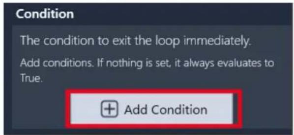
2. Tap the pull down list and select the condition type.
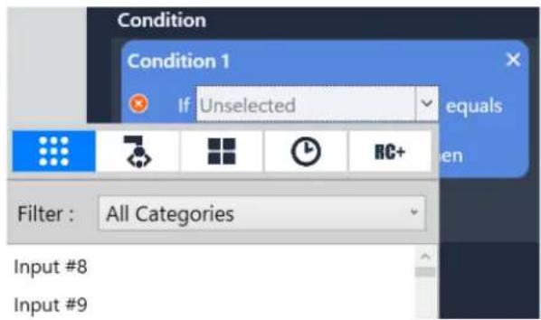
- Setting with ⋯ (Input signal bits)
Judges whether an input signal bit is specified state (ON/OFF).
Select Input bit number and the state of it like following.
"If (Input bits) equals (state: ON/OFF)"

- You can filter the list of Input bits by category to show less as you like. For the details of I/O types to show or Input bits, refer to the following. Setting for the I/O
- Input bits used by Remote I/O are not shown.

- Setting with (Hand)
Judges whether the hand is gripping a workpiece or not. Select like following below.
"If (Hand (Gripped / Released)) equals (True / False)"

- Setting with \_\_\_\_ (Pallet)
Judges whether the current position of the specified pallet is at its Begin position or End position. Input like following below.
“If (Pallet x) equals (Position: Begin / End) then”

- Setting with (Timeout)
Judges whether the last execution of "Grip", "Release", or "Wait" command timed out. Select in the following format:
“If (Grip / Wait timed out) equals (True / False)”
[Grip timed out]
If a timeout is set for the “Grip” operation in the Hand settings, the timeout can be set as a condition here.
General
[Wait timed out]
You can set whether the last "Wait" command timed out or not, as a condition.
Wait
- Setting with

This type of condition is shown only when RC+ project is imported using the RC+ Project Link feature.
Select the condition in the following format:
"If (Variable Label / Variable Name) equals (xx)"
Overview of the feature of RC+ Project Link
From the list of global variables defined in the imported RC+ Project, select the variable for which the condition is to be judged.
The format of the condition varies depending on the type of selected variable.
| Variable type Option/Input limit | Operator when setting the condition | ||
| Boolean | 2 bytes, True/False | True/False | = |
| Byte | 2-byte integer, -128 to +127 | Only integers can be entered | =><><=◇ |
| Integer | 2-byte integer, -32768 to 32767 | ||
| Short | 2-byte integer, -32768 to 32767 | ||
| In32 | 4-byte integer,-2147483648~2147483647 | ||
| In64 | 8-byte integer,-9223372036854775808~9223372036854775807 | ||
| Long | 4-byte integer,-2147483648~2147483647 | ||
| Ubyte | Unsigned 2-byte integer, 0 to 255 | 0 or a greater integer can be entered | =><><=◇ |
| Ushort | Unsigned 2-byte integer, 0 to 65535 | ||
| UInt32 | Unsigned 4-byte integer, 0 to 4294967295 | ||
| UInt64 | Unsigned 8-byte integer,0~18446744073709551615 | ||
| Real | 4-byte real number, significant digits: 6 | Only numerical values can be entered | =><><=◇ |
| Double | 8-byte real number, significant digits: 14 | ||
| String | ASCII characters only, 255 characters max. | =◇ | |
- Drag and drop the commands that you want to add to [Then] and [Else].
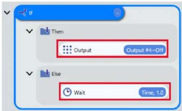
4. When multiple conditions are needed, tap <+> button to add conditions.
You can select operators between conditions when there are more than two conditions.
And: True if both condition A and B are satisfied.
Or: True if condition A or B is satisfied.

When multiple conditions are specified, they are always evaluated in order from the top to bottom. For example, when condition 1, 2, and 3 are specified, the pair of condition 1 and 2 is evaluated first with the operator in between. Then, its result and condition 3 are paired and evaluated. The last evaluation result is the total result of the evaluation. {(A and/or B) and/or C}
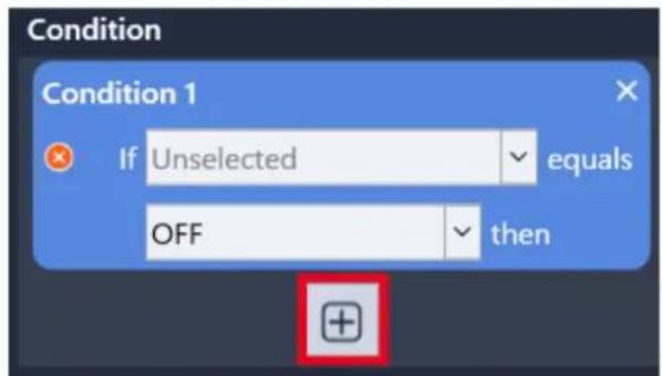
Comment
A command to show comment or explanation you inputted on the program. This command does nothing other than showing the comment in the program.
Quit
When the program hits this command, the program stops.
Ask
A command to ask a user a question while the program is running and branch its operation depending on the answer.
Tap an "Ask" command to the program and input a question to [OK] and [Cancel] (up to 122 characters) in the detail setting area.
When the program hits this command, an dialog window with the question is shown.
[OK]: The commands in the [OK] box is executed. [Cancel]: The commands in the [Cancel] box is executed.
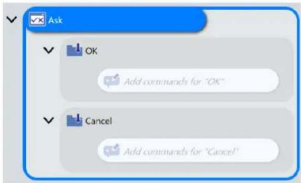

You can not use any double quotation character (“”) in the question.
Notify
A command to show a notification message and wait until the user responds. If the user replies [OK], the program is resumed.
Tap a "Notify" command to the program and input a notification message to [OK] (up to 122 characters) in the detail setting area.
When the program hits the command, a dialog window with the notification message is shown.
When answered [OK], the commands in the [OK] box are executed, and then the program continues to the next command.
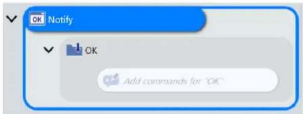

You can not use any double quotation character (“”) in the question.
Event Log
A command to print a message (up to 127 characters) into the event log.
When the program hits this command, the specified message is printed in the Event Log as shown below.
![EPSON RC - Express Edition 12.0.0 Virtual Program Grip Release Pallet Move forward Reset Logic Output Wait Loop if Undo Delete Save Cut Copy Paste Delete Skip Settings Event Log message xxxx Event Log Comment [Event Log] writes the specified message into the event log. Content Input the message to write into the event log. message xxxx 2021/05/13 19:48:07 message xxxx Copy to Clipboard Clear Event Log Start Finish Continue Stop Stop VO 3D View](/content/2026/05/821542/images/6cc79726d72950ed12db4606ceef101f12f04a300924492b175c924b065f2e1d.jpg)

You can not use any double quotation character (“”) in the question.
SPEL+ Command
A command to execute a raw SPEL+ code in a single line.
![[SPEL+ Command] is equivalent as "eval" of SPEL+. Code Input SPEL+ code to execute.](/content/2026/05/821542/images/5d9844a3f16186885f79c38b0b09426ddfe55fdfaaa2c5b86df139cf229d7173.jpg)
Following SPEL+ Commands are available:
Robot Control Commands
| SPEL+Command | Description |
| Reset | Resets the controller. |
| SFree | Removes servo power from the specified servo axis. |
| SLock | Restores servo power to the specified servo axis. |
| Jump | Jumps to a point using point to point motion. |
| Arch | Sets / returns arch parameters for Jump motion. |
| LimZ | Sets the upper Z limit for the Jump command. |
| LimZMargin | Sets / returns the margin for error detection when the operation starts at the position higher than LimZ value. |
| Sense | Specifies and displays the condition to stop the manipulator above the target coordinate when Sense is specified by Jump command. |
| Go | Moves the robot to a point using point to point motion. |
| Pass | Executes simultaneous four joint Point to Point motion, passing near but not through the specified points. |
| Pulse | Moves the robot to a position defined in pulses. |
| BGo | Executes Point to Point relative motion, in the selected local coordinate system. |
| BMove | Executes linear interpolation relative motion, in the selected local coordinate system. |
| TGo | Executes Point to Point relative motion, in the current tool coordinate system. |
| TMove | Executes linear interpolation relative motion, in the selected tool coordinate system. |
| Till | Specifies motion stop when input occurs. |
| TillOn | Returns the current Till status. |
| !...! | Process statements during motion. |
| Speed | Sets / returns speed for point to point motion commands. |
| Accel | Sets / returns acceleration and deceleration for point to point motion. |
| SpeedFactor | Sets / returns speed for point to point motion commands. |
| Inertia | Specifies or displays the inertia settings for the robot arm. |
| Weight | Specifies or displays the weight settings for the robot arm. |
| Arc | Moves the arm using circular interpolation. |
| Move | Moves the robot using linear interpolation. |
| SpeedS | Sets / returns speed for linear motion commands. |
| SpeedR | Sets / returns speed for tool rotation. |
| AccelR | Sets / returns acceleration and deceleration for tool rotation. |
| Home | Moves robot to user defined home position. |
| HomeClr | Clears the home position definition. |
| HomeSet | Sets user defined home position. |
| Hordr | Sets motion order for Home command. |
| Pallet | Defines a pallet or returns a pallet point. |
| PalletClr | Clears a pallet definition. |
| Fine | Specifies and displays the positioning error limits. (Unit: pulse) |
| FincDist | Specifies and displays the positioning error limits. (Unit: mm) |
| CP | Sets CP (Continuous Path) motion mode. |
| WaitPos | Waits for robot to decelerate and stop at position before executing the next statement while path motion is active. |
| XY | Returns a point from individual coordinates that can be used in a point expression. |
| PTPBoost | Specifies or displays the acceleration, deceleration and speed algorithmic boost parameter for small distance PTP (point to point) motion. |
| CX | Sets / returns the X axis coordinate of a point. |
| CY | Sets / returns the Y axis coordinate of a point. |
| CZ | Sets / returns the Z axis coordinate of a point. |
| CU | Sets / returns the U axis coordinate of a point. |
| JTran | Perform a relative move of one joint. |
| PTran | Perform a relative move of one joint in pulses. |
| SoftCP | Sets / returns SoftCP motion mode. |
| Hcre | Teach a robot point at the current position. |
| CP_Offset | Sets the offset time to start the subsequent motion command when executing CP On. |
| AvgSpeedClear | Clears and initializes the average of the joint speed. |
| PeakSpeedClear | Clears and initializes the peak speed for one or more joints. |
Input / Output Commands
| SPEL+Command | Description |
| On | Turns an output on. |
| Off | Turns an output off. |
| Oport | Reads status of one output bit. |
| Sw | Reads status of input. |
| In | Reads 8 bits of inputs. |
| InW | Reads the status of the specified input word port. |
| InBCD | Reads 8 bits of inputs in BCD format. |
| Out | Sets / returns 8 bits of outputs. |
| OutW | Outputs 1 word (16 bit) output data, used for I/O and memory I/O |
| OpBCD | Simultaneously sets 8 output bits using BCD format. |
| MemOn | Turns a memory bit on. |
| MemOff | Turns a memory bit off. |
| MemSw | Returns status of memory bit. |
| MemIn | Reads 8 bits of memory I/O. |
| MemOut | Sets / returns 8 memory bits. |
| MemInW | Returns the status of the specified memory I/O word port. Each word port contains 16 memory I/O bits. |
| MemOutW | Simultaneously sets 16 memory I/O bits. |
| Wait | Wait for condition or time. |
| TMOut | Sets default time out for Wait statement. |
| TW | Returns the status of the Wait condition and Wait timer interval. |
| InReal | Reads an input data of 2 words (32 bits) as a floating-point data (IEEE754 compliant) of 32 bits.This command is used for I/O. |
| OutReal | Output the output data of real value as the floating-point data (IEEE754 compliant) of 32 bits to the output port 2 words (32 bits).This command is used for I/O. |
Point Management Commands
| SPEL+ Command Description | |
| ClearPoints | Clears all point data in memory. |
| P# | Defines a specified point. |
| PDef | Returns the definition status of a specified point. |
| PDel | Deletes specified position data. |
| PLabel$ | Returns the point label associated with a point number. |
Program Control Commands
| SPEL+ Command Description | |
| Error | Generates a user error. |
For details of each SPEL+ command, refer to the following: SPEL + Language Reference
Variable
A command to assign a value to the global variable defined in the RC+ Project imported by RC+ Project Link.
Importing RC+ Project on RC+ EE
■Detailed Settings
Variable
Select a variable from the pull down list of variables.
Enter the value to be substituted in the selected variable in the control displayed under the pull down lost of variables.
The control in which a value is to be entered varies depending on the type of the selected variable.
Example: For Boolean data type
List box (The options are True/False)
Example: For Integer data type
Text box (Integers only)
| Variable type Option/Input restriction | ||
| Boolean | 2 bytes, True/False | True/False |
| Byte | 2-byte integer, -128 to +127 | Only integers can be entered |
| Integer | 2-byte integer, -32768 to 32767 | |
| Short | 2-byte integer, -32768 to 32767 | |
| In32 | 4-byte integer,-2147483648~2147483647 | |
| In64 | 8-byte integer,-9223372036854775808~9223372036854775807 | |
| Long | 4-byte integer,-2147483648~2147483647 | |
| Ubyte | Unsigned 2-byte integer, 0 to 255 | 0 or a greater integer can be entered |
| Ushort | Unsigned 2-byte integer, 0 to 65535 | |
| UInt32 | Unsigned 4-byte integer, 0 to 4294967295 | |
| UInt64 | Unsigned 8-byte integer,0~18446744073709551615 | |
| Real | 4-byte real number, significant digits: 6 | Only numerical values can be entered |
| Double | 8-byte real number, significant digits: 14 | |
| String | ASCII characters only, 255 characters max. | |
RC+ Project Link
This command calls the function defined in the RC+ Project imported by RC+ Project Link.
Importing RC+ Project on RC+ EE
Operation procedure
- Import a function from the RC+ Project.
- Select the imported command from the command area.
- Make detailed settings for the properties of the function.
Set the parameters to be passed to the function. The input format varies depending on the type of parameters.
Example: For Boolean data type List box (The options are True/False)
Example: For Integer data type Text box (Integers only)
| Variable type Option/Input restriction | ||
| Boolean | 2 bytes, True/False | True/False |
| Byte | 2-byte integer, -128 to +127 | Only integers can be entered |
| Integer | 2-byte integer, -32768 to 32767 | |
| Short | 2-byte integer, -32768 to 32767 | |
| In32 | 4-byte integer,-2147483648~2147483647 | |
| In64 | 8-byte integer,-9223372036854775808~9223372036854775807 | |
| Long | 4-byte integer,-2147483648~2147483647 | |
| Ubyte | Unsigned 2-byte integer, 0 to 255 | 0 or a greater integer can be entered |
| Ushort | Unsigned 2-byte integer, 0 to 65535 | |
| UInt32 | Unsigned 4-byte integer, 0 to 4294967295 | |
| UInt64 | Unsigned 8-byte integer,0~18446744073709551615 | |
| Real | 4-byte real number, significant digits: 6 | Only numerical values can be entered |
| Double | 8-byte real number, significant digits: 14 | |
| String | ASCII characters only, 255 characters max. | |
Various Program Examples (Tutorial)
Pick and Place (between 2 points)
This tutorial describes the basic usage of the program screen through creating a simple program.
Simple pick and place (between 2 points) is a program which moves a workpiece from point A to point B as shown in the figure below.
For example, a part which comes out of a processing equipment and placed at point A is transported to the conveyor at point B.
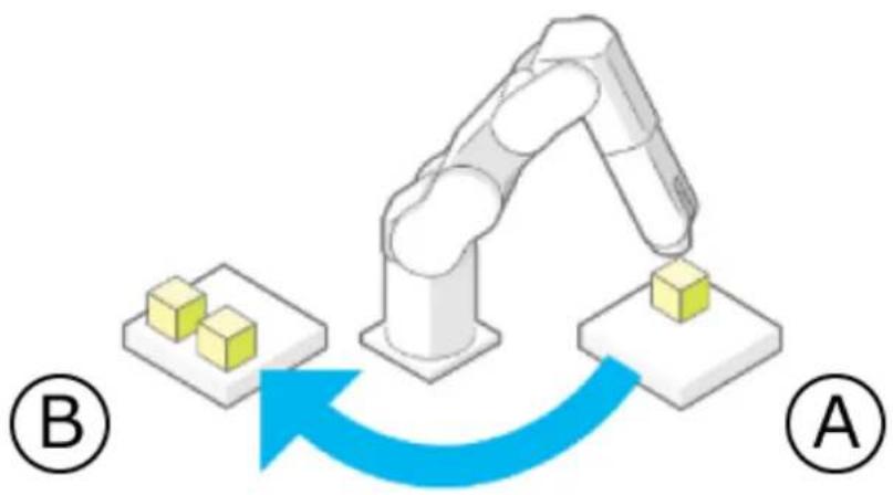
flowchart
graph TD
    A["Robot Arm"] --> B["Yellow Block 1"]
    B --> C["Yellow Block 2"]
    C --> D["Blue Arrow Down"]
    D --> E["Blue Arrow Up"]
    style A fill:#f9f,stroke:#333
    style E fill:#bbf,stroke:#333
Operation procedure
1. Tap |Create|.
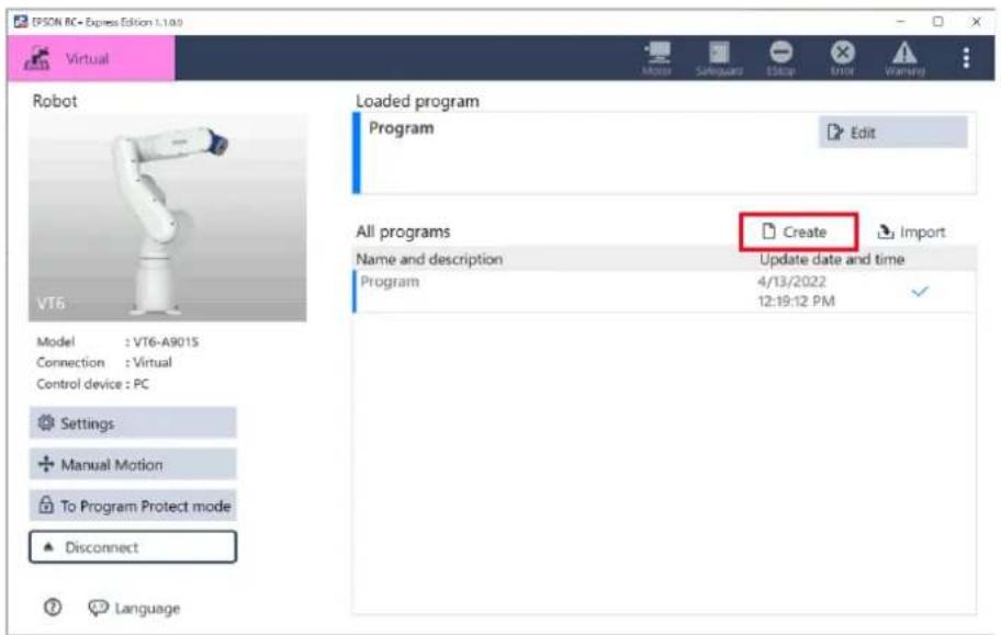
- When the following screen appears, confirm that [Empty Program] is selected.
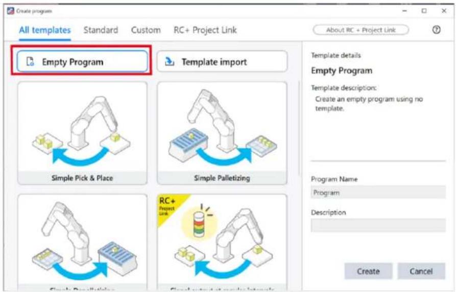
- Enter "Program Name" and "Description", and then tap the
button.
As an example, the followings are entered.
Program Name: PickandPlace
Description: Pick and place (between 2 points)
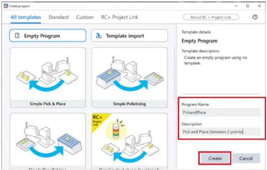
4. Tap [Edit].
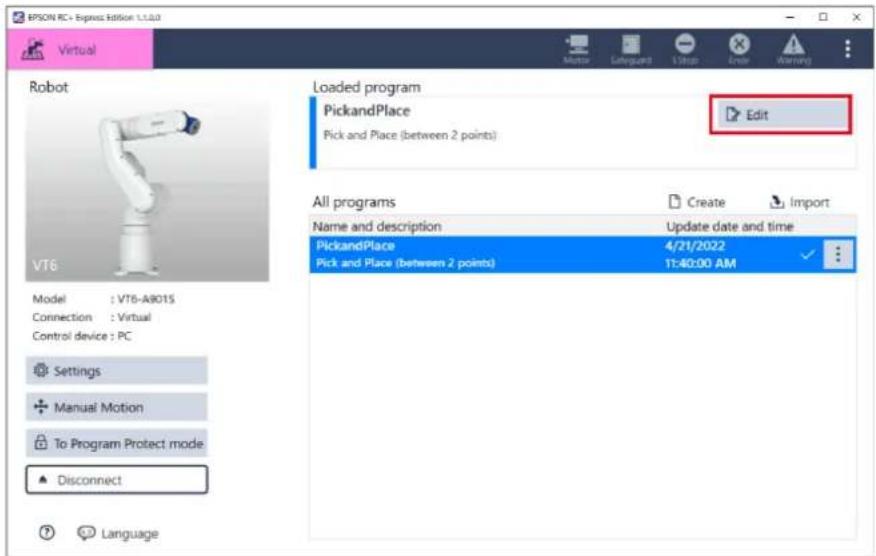
5. When the following screen appears, tap the "Motor On" command to add.
Motor turns On.
![PSON RC+ Express Edition 1.0.0 Virtual PickandPlace* Pick and Place (between 2 points) Motor ON Motor OFF Basic Move to Move linearly to Grip Release Container Pick & Place Pick from Place at Pallet Event Log Rehearsal Start Power Capture Clip Play Affairs Settings Motor ON Low Motor ON [Motor ON] turns on the motors to get the robot ready to operate. Power Select power mode: High Low UO 3D View](/content/2026/05/821542/images/67538ceeda7f18c6ac4a928a2ed10601d078f2b7e61bb35d320b022b3dc3afd8.jpg)
6. Follow the instructions below to configure the motion to move to a picking point and then grip a workpiece.
(1) Tap the "Pick from" command to add.
A series of operation commands are added.
The robot evacuates to Tool Z direction. You can set the waypoint in [Settings].
(2) Name the destination "Picking point".
(3) Tap the
Operating Robot
![EVSON RC+ Express Editor 1.1.0 Virtual PickandPlace* Pick and Place (between 2 points) Motor ON Motor OFF Basic Move to Move linearly to Grip Release Container Pick & Place Pick from Place at Pallet Event Log Rehearsal Start Help Cancel Stop Skip Settings Pick from Pick from Picking point Move to Approach Pt Move linearly to Destination Grip Wait Time, DS Move linearly to Departure Pt Pick from Destination Select the reference position of the destination. Find point Pilot Set the position of the destination. You can teach them using the [Jog & Teach] pane or edit the coordinate values directly below Jog & Teach Destination coordinates Specify the name of the destination. Picking point [Go here] is to move the robot arm to the position specified above. VO 3D View](/content/2026/05/821542/images/e0a0cf854c128b24fcf0c1226ea10769edfe098aa7ebc5476530483840e2fa84.jpg)
7. Follow the instructions below to configure the motion to move to the point where the workpiece is to be placed and then release the workpiece.
(1) Tap the "Place at" command to add.
A series of operation commands are added.
(2) Name the destination "Placing point".
(3) Tap the
Operating Robot
![EPCN RC - Express Edition 1.1.0.0 PickandPlace* Pick and Place (between 2 points) Place at Destination Select the reference position of the destination. Fixed point Pallet Set the position of the destination. You can teach them using the [jog & Teach] pane or edit the coordinate values directly below. Jog & Teach Destination coordinates Specify the name of the destination. Placing point [Go here] is to move the robot arm to the position specified above. Place at Move to Approach Pt. Move linearly to Destination Release Wait Time, 0.5 Move linearly to Departure Pt. Place at Grip Release Container Pick & Place Pick from Place at Pallet Event Log Rehearsal Start Finish Finish Help Help OK 3D View](/content/2026/05/821542/images/67284b8989dfa520c1c8461b1be48c019ad99a36d4a25cd5ea734183730181bc.jpg)
8. Follow the instructions below to configure the motion to repeat "Pick from" and "Place at".
(1) Tap the "Loop" command to add.
(2) Move the "Pick from" and "Place at" commands which configured in procedures 6 and 7 into the "Loop" command.
(3) Tap the <+> button in [Loop Count] to specify the number of times to repeat the motion.
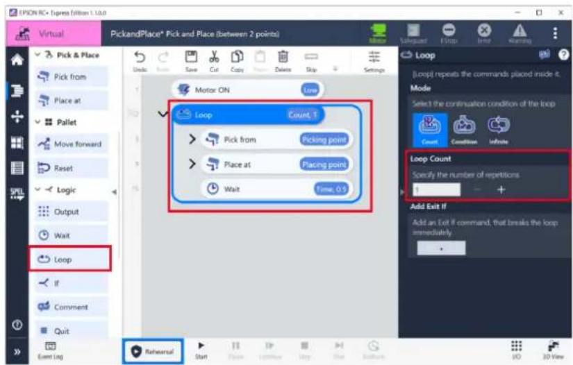
9. Tap [Start] to check for problems of the robot motion.
When connecting to a virtual robot, tap the <3D View> button to display the 3D View window.
Tap the
Executing a Program to Check for Problems
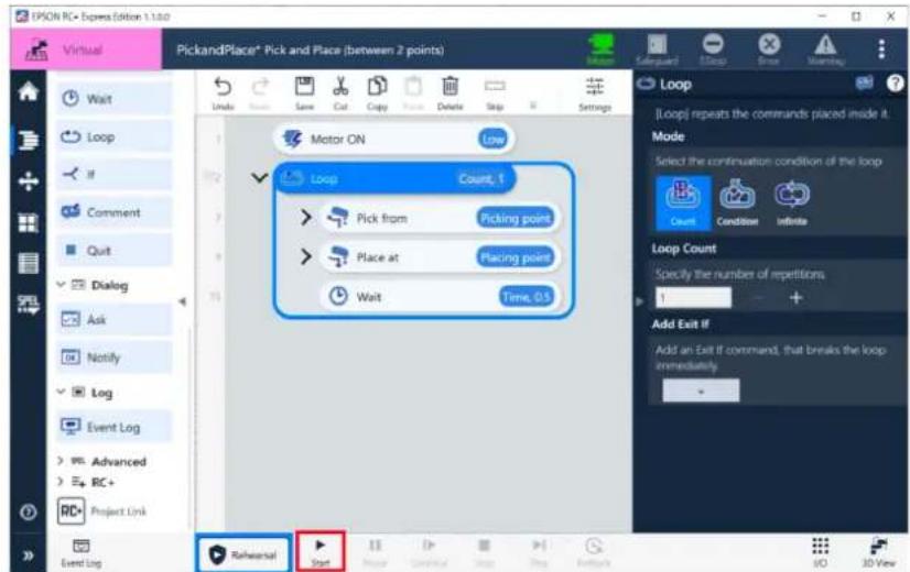
10. Tap the "Motor On" command in the program to set the [Power] to "High".
When you are confident that there is no problem for the robot motion, set the power to high.
![EPSON RC+ Expora Edition 1.1.dwg PickandPlace® Pick and Place (between 2 points) Motor ON High Loop Count 3 Pick from Picking point Place at Placing point Wait Time 0.5 Motor ON [Motor ON] turns on the motors to get the robot ready to operate. Power Select power mode. High Low Event Log Rehearsal Start Play Cut Copy Delete Skip Settings Load 3D View](/content/2026/05/821542/images/00773003e326a7d788622e1a4f17e0e754c0d4f3f9a29a31489574634d72751c.jpg)
11. Tap the button, and execute the program following the screen instructions.
Executing a Program to Check for Problems
Now, you have created the simple pick and place (between 2 points) program. The templates contain a series of commands to create a program. Using the template makes creating a program easier. Creating a Program Using a Template
Pick and Place (between 3 points)
This tutorial describes the procedure of editing an existing program through creating a pick and place (between 3 points) program based on the program created in [Pick and Place (between 2 points)].
Pick and Place (between 2 points)
Pick and place (between 3 points) is a program which moves a workpiece from point A to point B and waits for a while, and then moves it to point C as shown in the figure below.
Such a program pattern is used, for example, in machine tending applications where a workpiece carried by a conveyor is caught at point A, placed in the machining equipment at point B, and taken out after machining to point C.
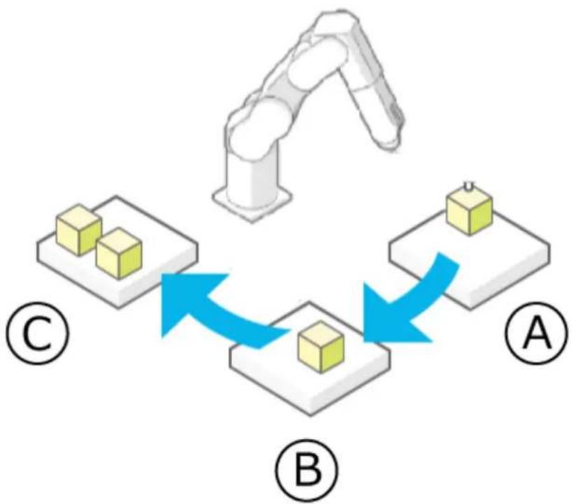
flowchart
graph TD
    A["Arm"] --> B["Central Unit"]
    B --> C["Block A"]
    B --> D["Block B"]
    D --> E["Block C"]
    style A fill:#f9f,stroke:#333
    style B fill:#ccf,stroke:#333
    style C fill:#cfc,stroke:#333
    style D fill:#fcc,stroke:#333
Operation procedure
- Tap -[Duplicate] on the program of pick and place (between 2 points).
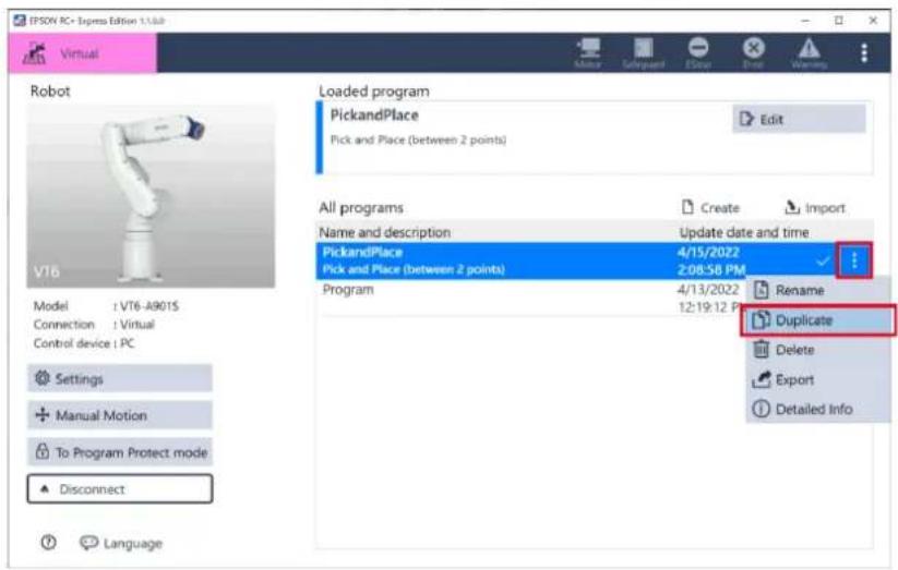
- Enter "Program Name" and "Description" then tap the
button.
As an example, enter the followings.
Program Name: PickandPlace_1
Description: Pick and place (between 3 points)
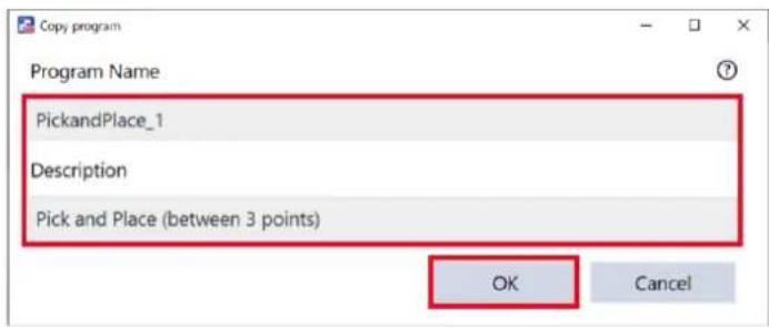
- Tap [Edit].

When another program is loaded, perform the following operations:
-
Tap the newly duplicated program in the "All programs" list.
-
Tap (Load) to load it.
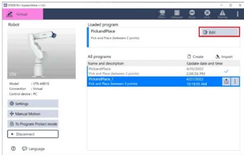
4. Follow the instructions below to configure the motion to move to a processing point and then release a workpiece.
(1) Tap the "Place at" command to add under the "Pick from" command.
A series of commands which moves a workpiece and place it at the processing point are added.
The robot evacuates to Tool Z direction. You can set the waypoint in [Settings].
(2) Name the destination "Processing point".
(3) Tap the
Operating Robot
![EPSON RC+ Express Edition 1.1.0 PickandPlace, 1* Pick and Place (between 3 points) Move Save Cut Copy Delete Skip Settings Place at [Place at] is a combined command that moves the robot arm to the destination and release hand. Destination Select the reference position of the destination Fixed point Pallet Set the position of the destination. You can teach them using the (log & Teach) plane or edit the coordinate values directly below. Jog & Teach Destination coordinates Specify the name of the destination. Processing point [Go here] is to move the robot arm to the position specified above. Place at Place at Place at Place at Rehearsal Start Close Custom Show Show OK 3D View](/content/2026/05/821542/images/792d01a7a48844a6fe450e9b1982e4baffc35b7fabf4001041633d5ab3eb116d.jpg)
5. Follow the instructions below to configure the motion to move to a fixed point.
(1) Tap the "Move linearly to" command to add under the "Place at" command (Processing point).
(2) Select "Fixed point" in [Destination].
(3) Name the destination "Processing standby point".
(4) Tap the
Operating Robot
![EPSON RC Express Edition 1.0.6 Virtual PickandPlace, 1* Pick and Place (between 3 points) Move linearly to Move linearly to Grip Release Container Pick & Place Pick from Place at Pallet Event Log Rehearsal Start Playt Delete Help Trap Actions Move ON Loop Count: Pick from Point1 Place at Processing point Move linearly to Point2 Place at Point3 Wait Time: 0.5 Move linearly to Move linearly to) moves the robot straight to the destination. Destination Select the reference position of the destination. Find point Pilot Set the position of the destination. You can teach them using the [Jog & Teach] pane or edit the coordinate values directly below. Jog & Teach Destination coordinates Specify the name of the destination. Processing standby point [Go here] is to move the robot arm to the position specified above. UO 3D View](/content/2026/05/821542/images/7a6382831a4ae5c9a84b302d3096825edafe2845766b1766537cb3bc4d3eff5d.jpg)
6. Follow the instructions below to configure the waiting time until the processing is completed.
(1) Tap the "Wait" command to add under the "Move linearly to" command.
(2) Tap to display the comment field and enter "Waiting for completion".
(3) Select "Time" in [Wait Target].
(4) Enter the waiting time until the processing is completed in [Time].
![EPSON RC - Express Edition 1.1.0 Virtual Pick and Place, 1* Pick and Place (between 3 points) Options Save Cut Copy Paste Delete Skip Settings Pick & Place Pick from Place at Pallet Move forward Reset Logic Output Loop If Comment Quit Event Log Motor ON Low Loop Count, 1 Pick from Point1 Place at Processing point Move linearly Processing standby... Wait Time, 1.0 Waiting for ... Place at Point2 Wait Time, 0.5 Wait for completion [Wait] waits until the specified conditions are satisfied. Wait Target Specify what to wait (time or input bits) Time Condition Wait Time Specify waiting time (Unit: seconds) 1.0 Rehearsal Start Next Cancel Stop Play Pullout UO 30 View](/content/2026/05/821542/images/0ef1bee30fdf514b24d726fc32c10be377f16327404c59448b903f014634e100.jpg)
7. Follow the instructions below to configure the motion to move to the processing point.
(1) Tap the "Pick from" command to add under the "Wait" command.
(2) Select "Fixed point" in [Destination].
(3) Name the destination "Processing point".
(4) Tap the
Manual Motion
![IPSON RC+ Express Mition 1.1.68 PickandPlace_1* Pick and Place (between 3 points) Move to Move linearly to Grip Release Container Pick & Place Pick from Place at Pallet Move forward Reset Logic Output Event Log Rehearsal Start Save Cut Copy Push Skip Settings Motor ON Loop Count: 1 Pick from Point1 Place at Processing point Move linearly Processing standby Wait Time, 1.5 Waiting for Pick from Processing point Place at Point2 Wait Time, 0.5 Pick from Comment [Pick from] is a combined command that moves the robot arm to the destination and grip hand. Destination Select the reference position of the destination. Fixed point Pallet Set the position of the destination. You can teach them using the [log & Teach] pane or edit the coordinate value directly below. Jog & Teach Destination coordinates Specify the name of the destination. Processing point](/content/2026/05/821542/images/ea424559c263b084071b9c48cb388277df0c620b57bf7931004865c4371c313f.jpg)
8. Tap the button to check for problems of the robot motion.
When connecting to a virtual robot, tap the <3D View> button to display the 3D View window.
Executing a Program to Check for Problems
![BPSON RC• Express Edition 1.1.08 PickandPlace, 1* Pick and Place (between 3 points) Move to Move linearly to Grip Release Container Pick & Place Pick from Place at Pallet Move forward Reset Logic Output Event Log Rehearsal Start Loop ON Count 1 Pick from Point1 Place at Processing point Move linearly Processing standby... Wait Time, 1.0 Waiting for Pick from Processing point Place at Point2 Wait Time, 0.5 Pick from Comment [Pick from] is a combined command that moves the robot arm to the destination and grip hand. Destination Select the reference position of the destination. Fixed point Pallet Set the position of the destination. You can teach them using the [log & Teach] pane or edit the coordinate values directly below. Jog & Teach Destination coordinates Specify the name of the destination. Processing point](/content/2026/05/821542/images/9203685a381e05d52dd1332eac5f4fd6ffc105d48b6a6114eddbf14ee2d3b924.jpg)
Now, you have created the pick and place (between 3 points) program.
Palletizing
This tutorial describes the basic usage of the program screen through creating a simple program.
Palletizing is a program which conveys a workpiece from point to pallet.
Define the order of the conveying. The program works to convey workpieces in the defined order.
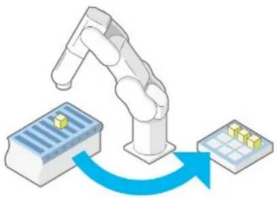
natural_image
Illustration of a robotic arm interacting with a microplate and a grid, showing data flow (no text or symbols)Operation procedure
1. Tap [Create].
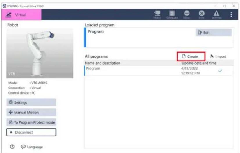
2. Confirm that [Empty Program] is selected.
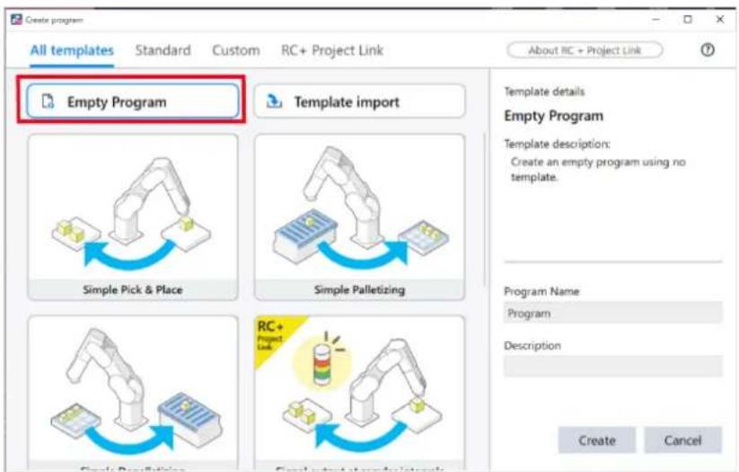
3. Enter "Program Name" and "Description", and then tap the button.
As an example, enter the followings.
Program Name: PointToPallet
Description: Conveying from point to pallet
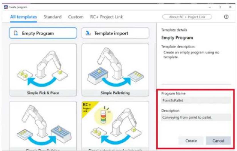
4. Tap [Edit].
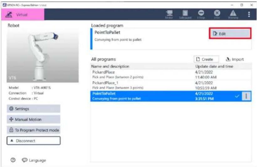
![EPSON RC+ Express - Tap [Edit]. - 2](/content/2026/05/821542/images/c86c4bb10b231ac87ae9c3c1f26622e67b2ee7caed69522381f923be30c2d28b.jpg)
When another program is loaded, perform the following operations:
- Tap the program.
- Tap (Load) to load the program.
5. When the editing screen appears, tap

to go to Pallets screen.
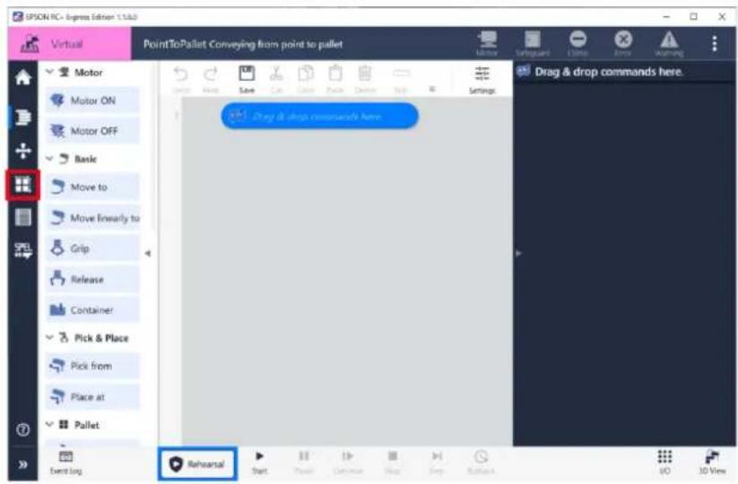
6. Tap the button.
![EPSOP RC+ Express Edition 1.1.02 Virtual PointToPallet Conveying from point to pallet Pallets Create a new pallet or edit a defined pallet. Push [Create] button to create a new pallet. Create Edit Delete UO 3D View](/content/2026/05/821542/images/ebd2d8fe49c2950fd4de0b1180005151ae664ddd473940222259a21cc4940782.jpg)
7. Set the number of cells using the <+> and <-> button, then tap the button.
As an example, create a 3 × 4 pallet.

8. Turn the motor "On" to teach the pallet position.
- With a workpiece placed on the pallet, move the robot to the position of point A and tap
button.
Operating Robot
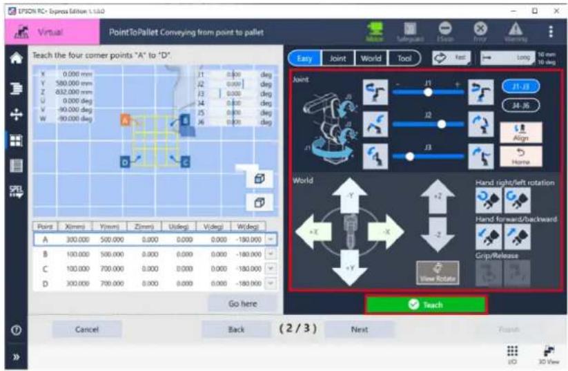

You can edit each coordinate value (X, Y, Z, U, V, W) directly.
- Teach all the 4 points and tap the
button.
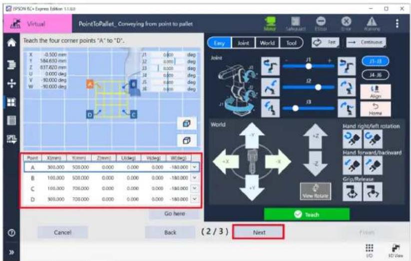
11. Select the |Begin| point of the palletizing and [Direction] from the begin point and tap button.
Now, you have created a pallet.
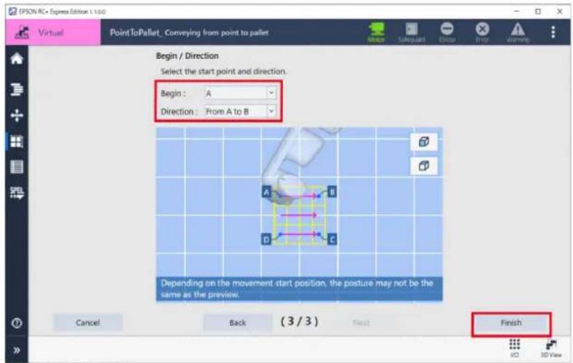
12. Go back to the program screen and follow the instructions below to add the "Motor On" and "Loop" commands.
Create a pick and place (between 2 points) program.
(1) Add the "Motor On" and "Loop" commands.
(2) Select "Infinite" in the property of the "Loop" command.
![EPSON RC+ Express Edition 1.1.03 Virtual PointToPallet® Conveying from point to pallet Release Container Pick & Place Pick from Place at Pallet Move forward Reset Logic Output Wait Loop # Event Log Rehearsal Start Save Cut Copy Delete Stop Settings Motor ON Low Loop Infinite Wait Time, 0.5 Loop [Loop] repeats the commands placed inside it. Mode Select the continuation condition of the loop Count Condition Indicate Add Exit If Add an Exit if command, that breaks the loop immediately VD 3D View](/content/2026/05/821542/images/cec2cc462310d88b45c9f3513401e225f724e5fb704b5ad6042ae62b09befe52.jpg)
13. Follow the instructions below to add the "Pick from" command above the "Wait" command and tap button.
(1) Tap a "Pick from" command into the loop.
(2) Select "Fixed point" as [Destination].
(3) Name the destination "Picking point".
![IPSON RC - Express Edition 1.1.00 Virtual PointToPallet® Conveying from point to pallet Release Container Pick & Place Pick from Place at Pallet Move forward Reset Logic Output Wait Loop # Event Log Rehearsal Start Save Cut Copy Paste Delete Skip Settings Motor ON Low Loop infinite Pick from Picking point Wait Time 0.5 Pick from Select the reference position of the destination. Foot point Foot Specify the name of the destination. Picking point Set the position of the destination. You can teach them using the [log & Teach] pane or edit the coordinate values directly below. X Y Z L1 Righty Jog & Teach [Go here] is to move the robot arm to the VO 3D View](/content/2026/05/821542/images/9841ab2f5a99b39c5769c90a8669077bb96b9eeeb0901be3f6e8f66ff379efb1.jpg)
14. Move the robot to the picking point and tap the button. Operating Robot
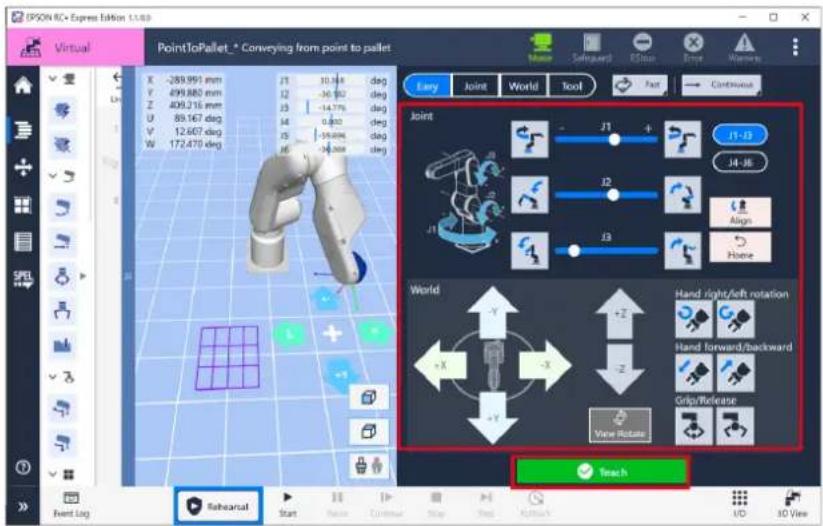
15. Follow the instructions below to add the "Place at" command and configure.
(1) Tap the "Place at" command to add.
(2) Select "Pallet" as [Destination].
(3) Select the pallet created in the step 12.
![IPSON RC+ Express Edition 1-1-M8 Virtual PointToPallet* Conveying from point to pallet Container Pick & Place Pick from Place at Pallet Move forward Reset Logic Output Wait Loop If Comment Event Log Rehearsal Start Make Delete Copy Delete Skip Settings Motor ON Low Loop infinite Pick from Picking point Place at Pallet1 Wait Time, 0.5 Place at [Place at] is a combined command that moves the robot arm to the destination and release hand. Destination Select the reference position of the destination. Fixed point Pallet Pallet1 Current orientation [Go here] is to move the robot arm to the position specified above. Go here Decompose commands Decompose into a set of normal commands to edit more details. Decompose UD 3D View](/content/2026/05/821542/images/88698af1c45e4ef9b9335aa7a69328ec2f4367f1c74623fb94c1a0eb34957807.jpg)
16. Follow the instructions below to add the "Move forward" command and configure.
(1) Tap the "Move forward" command to add.
(2) Select the pallet created in the step 12 in [Select a pallet.].
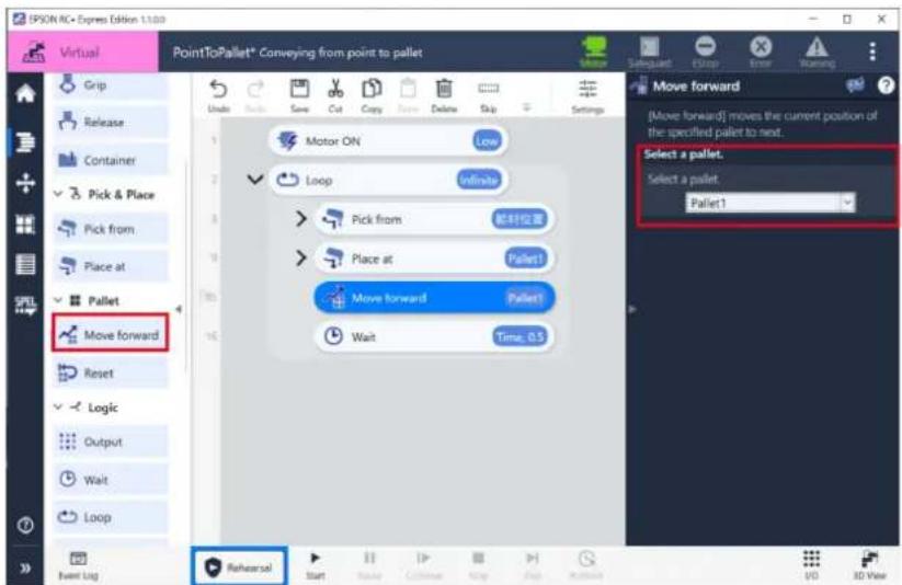
17. Tap [Start] to execute the program.
When connecting to a virtual robot, tap [3D View] to open the 3D View window.
Executing a Program to Check for Problems
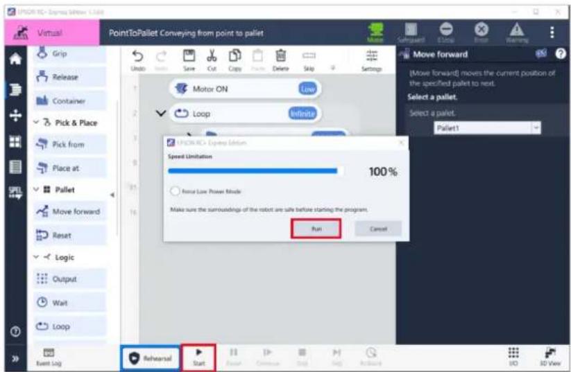
Now, you have created a palletizing program that conveys workpieces from a point to fill pallets with them.
This tutorial has explained how to create the program from scratch, but the same program can be created quickly using a built-in template.
Creating a Program Using a Template
Sorting Non-defective/Defective Products
This tutorial describes how to communicate with external devices from a program using the input/output (I/O) interface of a robot to realize a more complex application.
As an example, how to modify the program created in [Pick and Place (between 3 points)] into a program that sorts out good and defective products will be explained.
Pick and Place (between 3 points)
Assume that an external inspection machine is already wired to the robot controller and that its I/O interface specification is as follows.
| I/O bit (robot controller side) | Function of the inspection machine |
| Input Bit 8 | Done |
| Input Bit 9 | Results |
| Output Bit 10 | Start/Stop |
Operation procedure
1. Select - [Duplicate] on the program of pick and place (between 3 points).
Duplicate the base program.
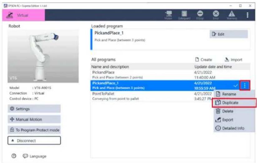
- Enter a name and description of program and tap the
button.
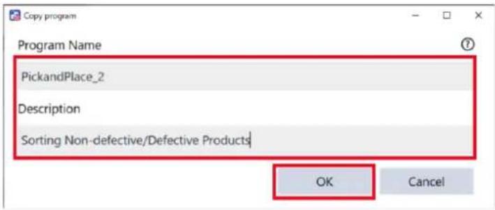
- Tap [Edit].
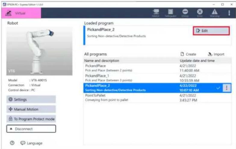
![EPSON RC+ Express - Select - [Duplicate] on the program of pick and place (between 3 points). - 4](/content/2026/05/821542/images/74fc39d6106316df2471ac25582d927ebb8f6143f0e48151f41089e69176312d.jpg)
When another program is loaded, perform the following operations:
-
Tap the pick and place (between 2 points) program.
-
Tap (Load) to load the program.
-
Tap [I/O].
With I/O monitor you can label the I/O bits connected to the inspection machine.
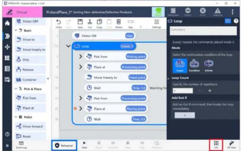
5. Tap the button.
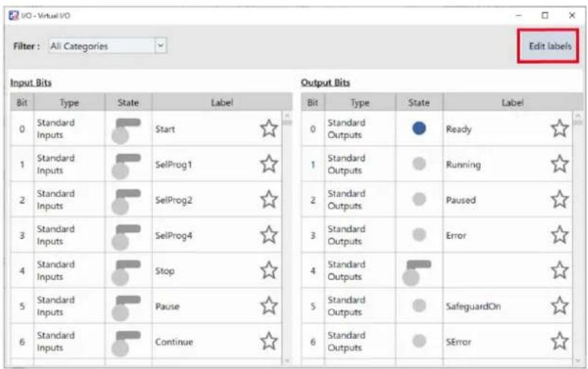
6. Enter the following and tap the
| Bit | Label |
| Input Bit 8 | Done |
| Input Bit 9 | Results |
| Output Bit 10 | Start/Stop |
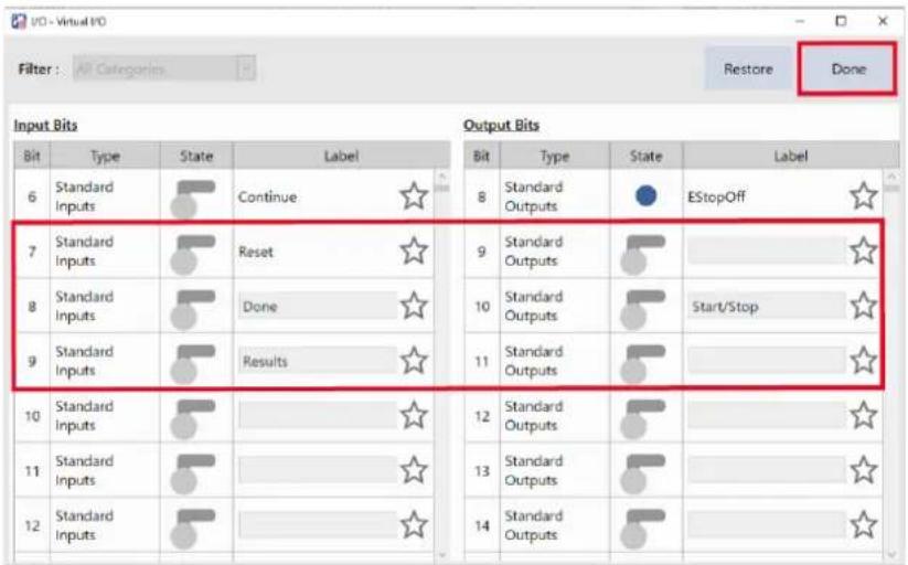
7. Follow the instructions below to add a command that instruct the inspection machine to start inspection from the program.
(1) Tap an "Output" command to just below the "Move linearly to" command. Be sure that the robot is at the waiting position when starting/stopping the inspection.
(2) Select "Output #10 Start/Stop" as [Output Target].
(3) Select "ON" as [Signal].
(4) Tap 📄, then enter "Start inspection" in the comment field.
![ISON RC > Express Edition 1.1.0 PickandPlace_2* Sorting Non-defective/Defective Products Output Start inspection [Output] outputs ON/OFF signal to the specified output bit Output Target Specify output bit# Output #10 Start / Stop Signal Select ON or OFF signal: ON Motor ON High Loop Count 1 Pick from Picking point Place at Processing point Move linearly to Fixed point Output Start / Stop=ON Start inspection Wait Time, 1.0 Wainting for Pick from Processing point Place at Placing point Wait Time, 0.5 Event Log Rehearsal Start Place Common Step Help Review ISO 3D View](/content/2026/05/821542/images/b3023e6943d2fc6a5d40e51fe929f6a69afbf20ad41bcc0d25a7bd2b334bc40f.jpg)
8. Follow the instructions below to add the second "Output" command and configure.
(1) Tap the "Output" command to just below the "Wait" command.
(2) Select "Output #10 Start/Stop" as [Output Target].
(3) Select "OFF" as [Signal].
(4) Enter "Stop inspection" in the comment field.
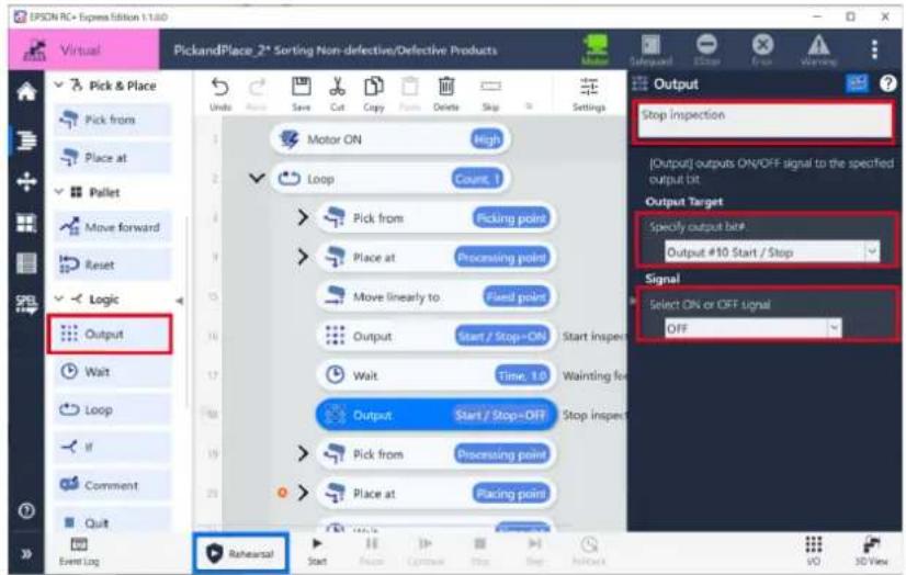
9. Follow the instructions make the program wait for the result from the inspection machine.
(1) Tap the "Wait" command on the program.
(2) Select "Condition" in [Wait Target].
(3) Specify "If Input #8 Done equals ON then" as [Condition].
![IPSON RC+ Express Edition 1.1.50 PickandPlace, 2* Sorting Non-defective/Defective Products Pick from Place at Pallet Move forward Reset Logic Output Wait Loop if Comment Quit Dialog Event Log Rehearsal Start Save Cut Copy Delete Skip Settings Count 1 Pick from Picking point Place at Processing point Move linearly to Fixed point Output Start / Stop-ON Start inspection Wait Done-ON 19.8 Wainting for Output Start / Stop-OFF Stop inspection Pick from Processing point Place at Placing point Wait Time 0.3 Wait for completion [Wait] waits until the specified conditions are satisfied. Wait Target Specify what to wait (time or input bits) Time Condition Condition 1 Input #8 Done equal ON then Timeout Specify timeout duration. If you specify a non-zero value here, the program resumes regardless of the condition after the duration. OK 3D View](/content/2026/05/821542/images/f38322b92db2db3167606f20dbb7fc760d99f0ef649d579fcaaf5e3ede65c443.jpg)
10. Follow the instructions below to make the program branch depending on the inspection result.
Configure the program to change the action according to inspection results.
(1) Tap an "If" command to just below the "Pick from"(Processing point) command.
(2) In [Condition], tap the
(3) Enter "Check the inspection results and sort" in the comment field.
![PickandPlace, 2* Sorting Non-defective/Defective Products Check for the inspection results and sort [1] executes "Then" if the specified conditions are satisfied. Otherwise it executes "Else" Condition Condition 1 if Input #9 Results equals ON then if Results=ON Check for Then Else Place at Placing point Wait Time, 0.5 Event Log Rehearsal Start Save Cut Copy Copy Delete Stop Settings Pick from Place at Pallet Move forward Reset Logic Output Wait Loop if Comment Quit Dialog If](/content/2026/05/821542/images/0a211363f57b7d78fb5293a21a9b5657bd674498bd7d1faa5b849cdbec931657.jpg)
11. Follow the instructions below to make the program handle non-defective products.
(1) Move the "Place at" (placing point) command into the "Then" command.
(2) Name the destination "Placing point (non-defective products)".
![IPSON RC+ Express Edition 1.1.04 Pick and Place_2* Sorting Non-defective/Defective Products Move To Processing points Output Start/Stop=ON Start inspection Wait Done=ON, 0.0 Waiting for completion Output Start/Stop=OFF Stop inspection Pick from Processing points If Results=ON Check the inspection Then Place at: Placing point (non... Else Wait Time, 0.5 Place at Constant [Place at] is a combined command that moves the robot arm to the destination and release hard. Destination Select the reference position of the destination. Front point Pallet Specify the name of the destination. Placing point (non-defective products) Set the position of the destinations. You can teach them using the [Blog & Teach] pane or edit the coordinate values directly below. Teach: 323.778 mm Teach: 211.104 mm Teach: 0.000 mm Event Log Rehearsal Start Close Cancel Stop Skip Button](/content/2026/05/821542/images/0677157d111253d57f518e7cd51ee1628237aebde1288a0f821552ac635cea24.jpg)
12. Follow the instructions below to configure the "Then" command.
(1) Tap the "Event Log" command to just below the "Place at" "Place at" (placing point (non-defective products)) command. By doing this, the records of sorting good and defective products are logged.
(2) Enter "OK" in [Content].
![IPSON RC+ Express Edition 1.1.0.0 Virtual PickandPlace_2* Sorting Non-defective/Defective Products Event Log [Event Log] writes the specified message into the event log. Content Input the message to write into the event log. OK Output Start/Stop=ON Start inspection Wait Done=ON 0.0 Waiting for completion Output Start/Stop=Off Stop inspection Pick from Processing point If Results=ON Check the inspection Then Place at Placing point (non... Event Log Else Wait Time 0.5 Event Log Event Log Advanced RC+ Project Link Rehearsal Start Action Control Help Help GO 3D View](/content/2026/05/821542/images/45d53df064e198ee2a31ee38818be0361787bc48eb53f6568b75607124d98071.jpg)
13. Follow the instructions below to configure the "Else" command.
(1) Copy the "Place at" commands created in the procedure 11 and paste into the "Else" command.
(2) Rename its destination "Placing point (defective products)".
(3) Tap the
Operating Robot
![UPSON RC+ Express Edition 1.1.0.0 PickandPlace_2* Sorting Non-defective/Defective Products Place at Select the reference position of the destination. Front point Reset Specify the name of the destination. Placing point (defective products) Set the position of the destination. You can teach them using the [log & Teach] pane or edit the coordinate values directly before X Teach: 397.341 mm Y Teach: 30.389 mm Z Teach: 0.000 mm U Teach: 10.000 deg Teach: Rightly - Jog & Teach Event Log Rehearsal Start Cancel Stop View OK Time, 0.5 Event Log Event Log Project Link Event Log Take from Processing point If Results=ON Check the inspection re Output Star/Stop=Off Stop inspection Pick from Then Place at Placing point Iron... Event Log OK Else Place at Placing point side... Wait Time, 0.5](/content/2026/05/821542/images/64ead365d86be93d5fe24963bba8d506ec66303934b76cf43b017392d5f0aa6c.jpg)
14. Follow the instructions below to add the "Event Log" command and configure.
(1) Tap the "Event Log" command to just below the "Place at" (placing point (defective products)) command.
(2) Enter "NG" in [Content].
![EPCN RC Express Edition 1.1.03 Virtual PickandPlace_2* Starting Non-defective/Defective Products Event Log [Event Log] writes the specified message into the event log. Content Input the message to write into the event log NG Output Start/Stop=OFF Stop inspection Pick from Processing point If Results=ON Check the inspection re Then Place at Placing point (non... Event Log Else Place at Placing point (date... Event Log Wait Time 0.5 Event Log Event Log VIt Advanced RC+ Project Link Rehearsal Start End](/content/2026/05/821542/images/fc7df84165e51939089ee34c5b14b61f4a851795f1bf6e167cafe3900f80b8ac.jpg)
15. Tap [Start] to check for problems of the robot motion.
When connecting to a virtual robot, tap [3D View] to open the 3D View window.
Executing a Program to Check for Problems
![IPSON RC+ Express Edition 1.1.00 Virtual PickandPlace_2* Sorting Non-defective/Defective Products Event Log [Event Log] writes the specified message into the event log. Content Input the message to write into the event log NG Wait Loop if Comment Quit Dialog Ask Notify Log Event Log > NC Advanced > RC+ RC+ Project Link Event Log Rehearsal Start](/content/2026/05/821542/images/0bd4e638c3dfec263279b1f0b59355c62cd3eb0ffa596c0ecfe694dbb20df68d.jpg)
Now, you have created a program to sort non-defective/defective products.
Fixed Cycle Signal Output (RC+ Project Link)
This tutorial describes basic usage of RC+ Project Link through creating a program that outputs a signal periodically to an external device, such as a flashing stack light. A built-in template will be used to do this rapidly. RC+ Project Link
Assume that a flashing light is already wired to the robot controller and that its I/O interface specification is as follows.
In this tutorial, we will create a program that flashes the light every 0.5 seconds while the robot is operating.
| Bit | Assignment |
| Output bit 9 | Light |
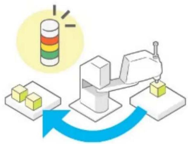
natural_image
Illustration of a robotic arm with a yellow cylindrical component and two yellow blocks on the left, connected by a blue curved arrow (no text or symbols)Operation procedure
1. Tap [Create].
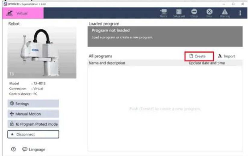
2. When the following screen is displayed, select [Fixed Cycle Signal Output].
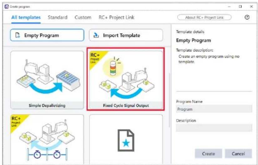
3. Enter "Program Name" and "Description" then tap the button.
As an example, the followings are entered.
Program Name: SignalOutput
Description: SignalOutput
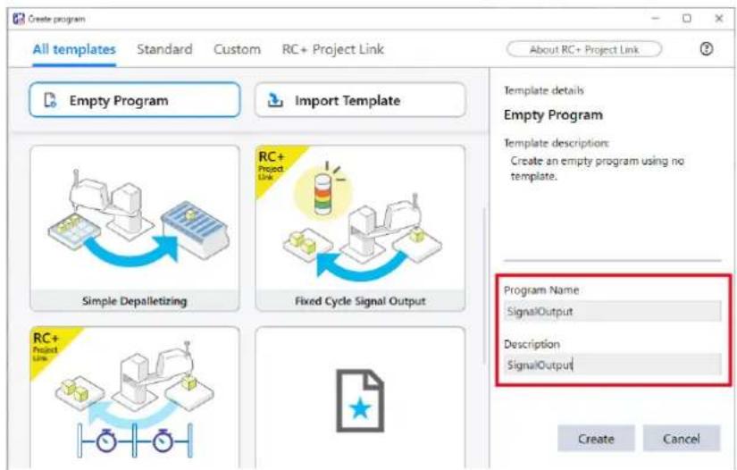
4. Tap [Edit].
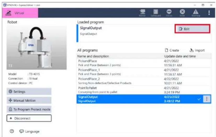
![EPSON RC+ Express - Tap [Edit]. - 2](/content/2026/05/821542/images/7a49808c100c88fe417c965066bcf3fe2b663a3a7d9b5f35706f91cdd0bf8e94.jpg)
When another program is loaded, perform the following operations:
-
Tap the program to be loaded.
-
Tap (Load) to load the program.
5. Tap [I/O].
With I/O monitor you can label the I/O bit connected to the flash light.
![OPSON RC+ Express Edition 1.1.0.0 Virtual SignalOutput SignalOutput Motor ON Motor ON Motor OFF Basic Move To Grip Release Container Pick & Place Pick from Place at Pallet Move forward Event Log Reversal Start Action Cut Copy Delete Skip Settings Save Cut Copy Paste Stop Motor ON Low RC+ Blinking start Pick from Point1 Place at Point2 Motor OFF RC+ Blinking end Motor ON [Motor ON] turns on the motors to get the robot ready to operate. Power Select power mode. High Low VO 3D View](/content/2026/05/821542/images/d0a71fed08c535a82172384128c503b7966bdf8661bdee6b24c334898c6a77af.jpg)
6. Tap the button.
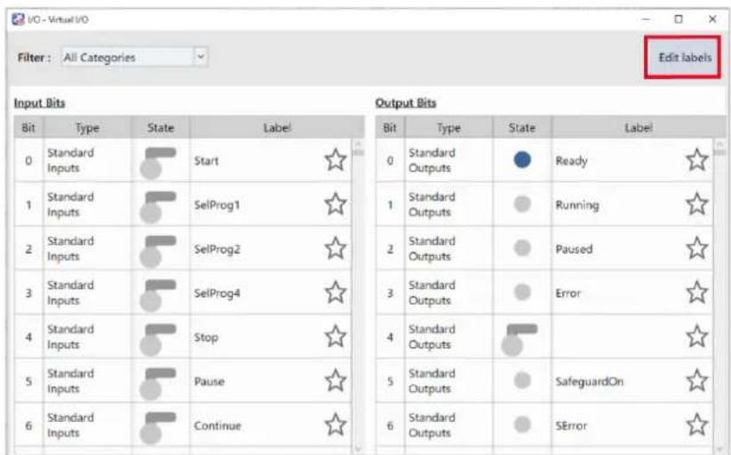
7. Enter the following and tap the
| Bit | Assignment |
| Output bit 9 | Light |
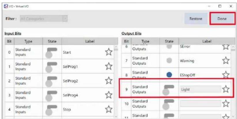
8. Follow the instructions below to configure the "Start Flashing" command.
(1) Assign "9", which is the output bit number connected to the light, to [Output I/O No.].
(2) Assign "0.5", which is the period for flashing a light, to [Flashing Cycle].
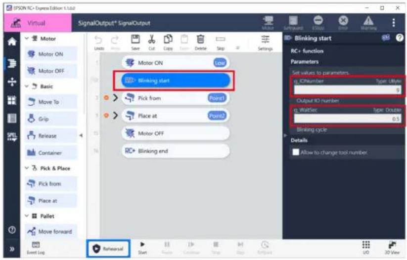
9. Create motion of the robot.
Create an operation to be performed by the robot. By selecting the template, the [Pick from] and [Place at] commands are set in advance.
Create a program for Pick and place (between 2 points) and so on by using these commands.
10. Tap [Start] to check for problems of the robot motion.
When connecting to a virtual robot, tap <3D View> button to open the 3D View window.
Executing a Program to Check for Problems
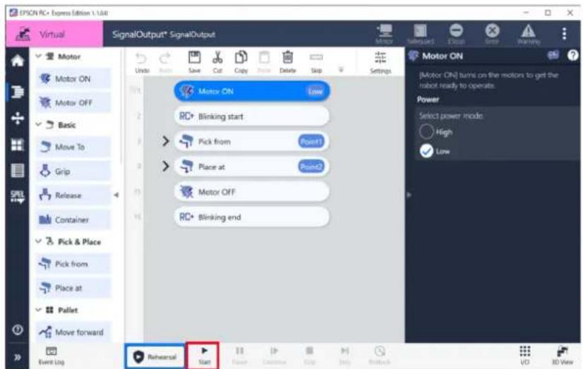
Now, you have created a program which outputs a signal periodically.
Cycle Time Measurement (RC+ Project Link)
This tutorial describes how to use RC+ Project Link through creating a program of which cycle time can be easily measured. A built-in template will be used to do this rapidly.
RC+ Project Link
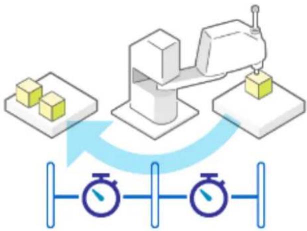
flowchart
graph TD
    A["Processing Unit"] --> B["Measurement Device"]
    B --> C["Control Panel"]
    C --> D["Data Bus"]
    style A fill:#f9f,stroke:#333
    style B fill:#ccf,stroke:#333
    style C fill:#cfc,stroke:#333
    style D fill:#fcc,stroke:#333
Operation procedure
1. Tap [Create].
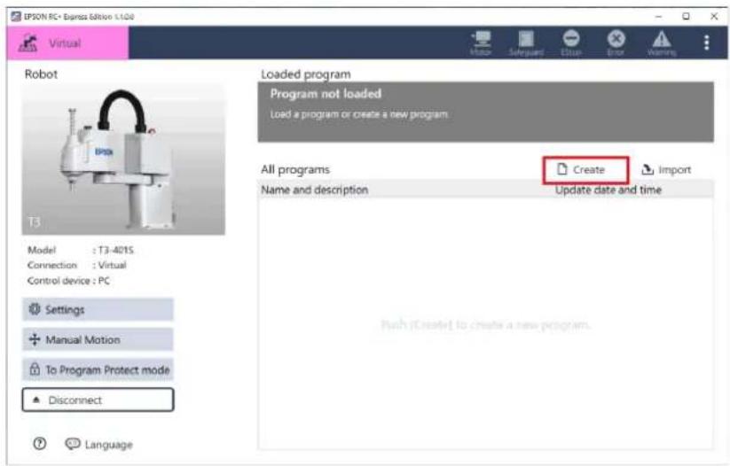
- When the following screen is displayed, select [Cycle Time Measurement].
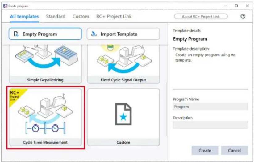
- Enter "Program Name" and "Description" then tap the
button.
As an example, the followings are entered.
Program Name: CycleTime
Description: Cycle Time Measurement
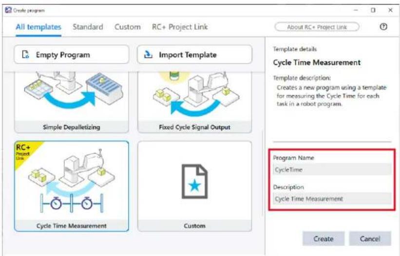
4. Tap [Edit].
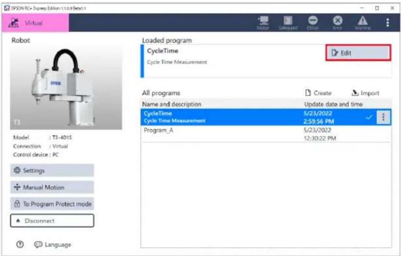
![EPSON RC+ Express - Tap [Edit]. - 2](/content/2026/05/821542/images/99623ab0c7d3a77120d686920fb74e73a9bce7bf40fbf667d3935e136624699f.jpg)
When another program is loaded, perform the following operations:
-
Tap the program to be loaded.
-
Tap (Load) to load the program.
5. Create motion of the robot.
Some [Pick from] and [Place at] command is set in advance, but change them as you wish.
The cycle time of the operation between the [Start Timer] command and the [End Timer] command can be measured.
![IPSON RC - Express Edition 1.3.00 Virtual CycleTime cycle Time Measurement Motor Motor ON Motor OFF Basic Move To Grip Release Container Pick & Place Pick from Place at Pallet Move forward Event Bag Rehearsal Start Save Cut Copy Paste Delete Skip Settings Motor ON Low RC* Timer A start Pick from Point1 Place at Point2 RC* Timer A ends RC* Timer B start Pick from Point3 Place at Point4 RC* Timer B ends Motor OFF Pick from Point1 Select the reference position of the destination. Find point Pallet Specify the name of the destination. Point1 Set the position of the destination. You can teach them using the [Dog & Teach] pane or edit the coordinate values directly below. A 400,000 mm/ Y 0,000 mm/ Z 0,000 mm/ U 0,000 kg/ Correct reorientation - V1 V2 V3 V4 V5 V6 V7 V8 V9 V10 V11 V12 V13 V14 V15 V16 V17 V18 V19 V20 V21 V22 V23 V24 V25 V26 V27 V28 V29 V30 V31 V32 V33 V34 V35 V36 V37 V38 V39 V40 V41 V42 V43 V44 V45 V46 V47 V48 V49 V50 V51 V52 V53 V54 V55 V56 V57 V58 V59 V60 V61 V62 V63 V64 V65 V66 V67 V68 V69 V70 V71 V72 V73 V74 V75 V76 V77 V78 V79 V80 V81 V82 V83 V84 V85 V86 V87 V88 V89 V90 V91 V92 V93 V94 V95 V96 V97 V98 V99 V100](/content/2026/05/821542/images/0588ee3729df2d5dda23575f3803bf94822aa59b6859e75a12131820c2be81cf.jpg)
6. Tap [Start] to check the robot motion.
When connecting to a virtual robot, tap the <3D View> button to open the 3D View window. Executing a Program to Check for Problems
![IPSON RC + Express Edition 1.1.0 Virtual CycleTime cycle Time Measurement Motor Motor ON Motor OFF Basic Move to Grip Release Container Pick & Place Pick from Place at Pallet Move forward Event Log Rehearsal Start Save Cut Copy Delete Skip Settings Motor ON Low RC+ Timer A start Pick from Point1 Place at Point2 RC+ Timer A ends RC+ Timer B start Pick from Point3 Place at Point4 RC+ Timer B ends Motor OFF Pick from) Select the reference position of the destination. Find point Point Specify the name of the destination. Point1 Set the position of the destination. You can teach them using the (log & Teach) pane or edit the coordinate values directly below. x 400.000 [mm] y 0.000 [mm] z 0.000 [mm] U 0.000 [deg] Current settings I/O ISO View](/content/2026/05/821542/images/265c6dc12609d081c7386237b5ab8ff51d91dd444a1e707a29c32c52e93f9b1e.jpg)
7. Check the measured cycle time.
When the operation of the program has finished, the results are displayed in the event log.
![EPSON RC - Expression LLC Virtual Cycle Time Cycle Time Measurement Motor ON Motor OFF Basic Move To Grip Release Container Pick & Place Pick from 2022/04/25 16:24:39 Timer A is5.134sec Copy to Clipboard Clear Recent Log Rehearsal Start Enter Cut Copy Delete Skip Settings Place at [Place at] is a combined command that moves the robot arm to the destination and release hand. Destination Select the reference position of the destination. First page Point Specify the name of the destination. Point2 Set the position of the destination. You can teach them using the [log & Teach] pane or edit the coordinate values directly below. X: 300.000 Temp](/content/2026/05/821542/images/400f5aa95dff9aa962a58cb6efa993bf05472dcc578dd5ed6c482245e89270e7.jpg)
The time between the [Start Timer A] command and the [End Timer A] command in the program is printed in the event log as Time A. Time B is also printed.
Now, you have created a program to measure a cycle time.
Pallet
Pallet Configuration
In pallets tab, you can create (up to 16 pallets), edit, delete pallet.
The pallets created in this tab, can be referred from pallet commands in the program.

To go to Pallets tab, tap on the left of [Edit] screen.
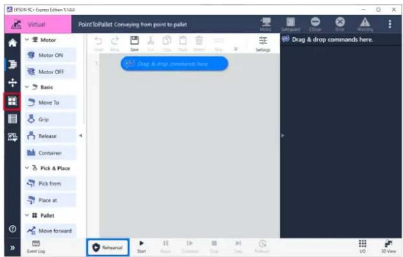
Creating a New Pallet
This page describes how to create a new pallet.

RC+ EE uses pallets 1 to 7. If you are using RC+ Project Link, use pallet 8 to 16 for RC+ to avoid a conflict.
Conditions to Use RC+ Project Link
Operation procedure
1. Tap the button.
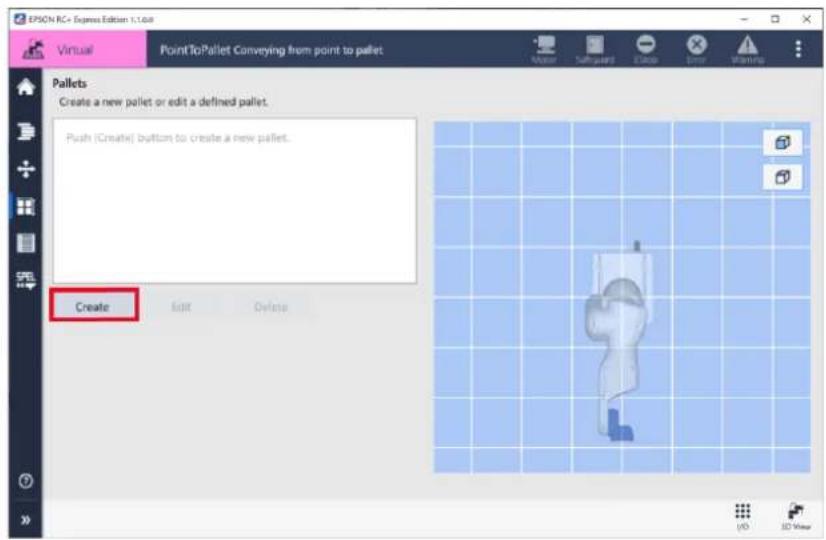
- Enter the number of rows and columns with + / - button and tap the
button.
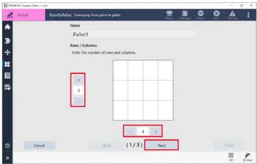
-
Turn the motor "On". Motor
-
Move the robot to the point A and tap
button. Teach the four points A to D at the corners of the pallet. You can also enter the X, Y, Z, U, V, and W point manually. Operating Robot
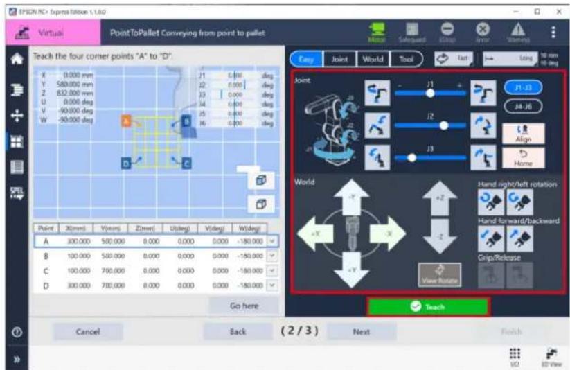
- Teach other points (B, C, D) and tap the
button.
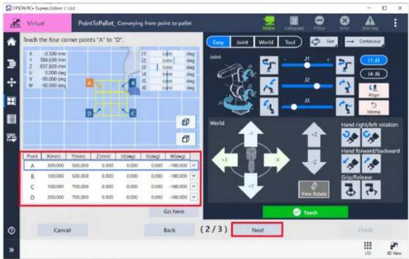
- Select beginning point and direction on the pallet and tap
button.
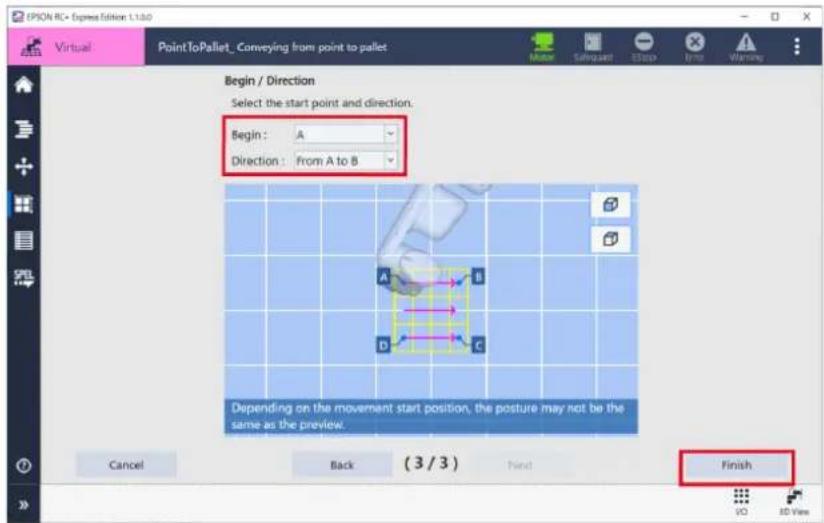
Point File Viewer
Point File Viewer Screen
In the point file Viewer screen, robot posture and point information can be viewed and edited.
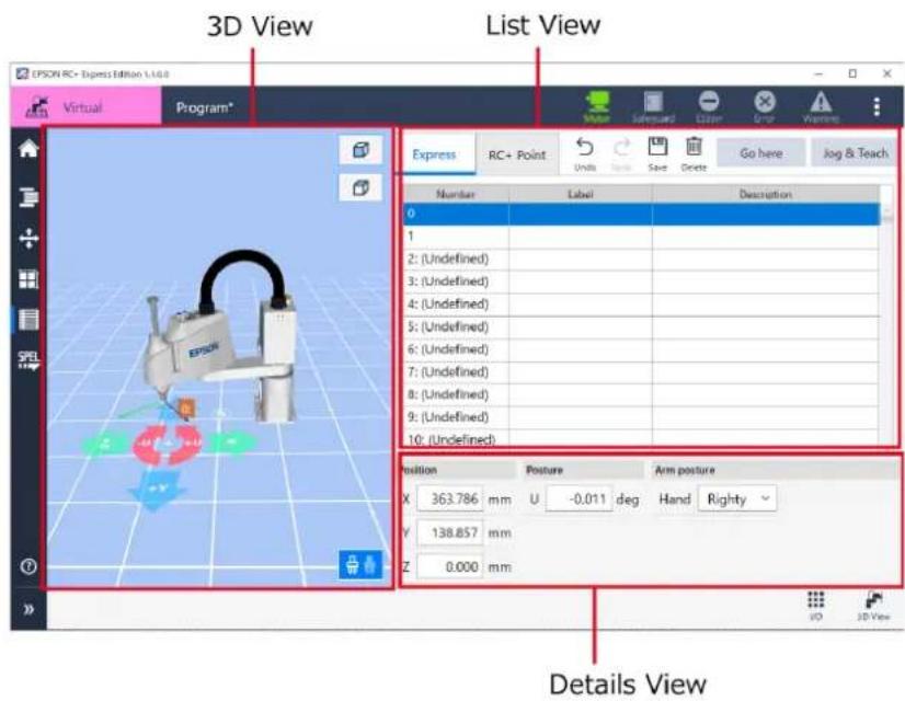
| Name of View Description | |
| 3D view | The robot posture and points are displayed in 3D model. |
| List View | The point file information for this software and RC+ is displayed. |
| Details View | The selected point coordinates are displayed in the World coordinate system. |
Defining a Point
3D View (Point File)
The following objects and buttons appear in the 3D view of the Point File Viewer:
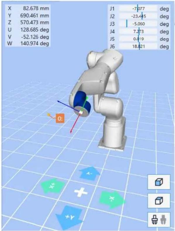
| Item Description | |
 | Point number and label. The selected point is displayed in a different color from the other points. |
 | Robot is displayed as translucent. The posture of the robot after the selected point is taught displayed as non-translucent. |
 | The view is set to view the robot from the top. |
 | The view is set to view the robot from the front. |
List View
List View displays the information in the point file in order of the point number.
| Number | Label | Description |
| 0: (Undefined) | ||
| 1: (Undefined) | ||
| 2: (Undefined) | ||
| 3: (Undefined) | ||
| 4: (Undefined) | ||
| 5: (Undefined) | ||
| 6: (Undefined) | ||
| 7: (Undefined) | ||
| 8: (Undefined) | ||
| 9: (Undefined) |
| Item | Description |
| Express / RC+ Point tabs | Express: the point information defined on RC+ EE. |
| RC+ Point tab: the point information imported with RC+ Project Link. | |
| Number | Point numbers. When the [Express] tab is selected, 0 to 499 are displayed. When the [RC+ Point] tab is selected, 500 to 999 are displayed. |
| Label | Labels of points. |
| Description | Description for points. |
Details View
In the details view, the selected point coordinates are displayed in the world coordinate system.
| Position & Posture | Others | ||||||||
| Position | Posture | Arm posture | |||||||
| X | Undefined | mm | U | Undefined | deg | Hand | Undefined | J1Flag | Undefined |
| Y | Undefined | mm | V | Undefined | deg | Elbow | Undefined | J4Flag | Undefined |
| Z | Undefined | mm | W | Undefined | deg | Wrist | Undefined | J6Flag | Undefined |
| Item | Description |
| Point information | The selected point number, label, and description are displayed.Select [Others] to display Flag that is not currently displayed and so on. |
| Position | X, Y, and Z of the point are displayed. |
| Posture | U, V, and W of the point are displayed. |
| Arm posture | Hand, Elbow, Wrist, J1, J4, and J6Flag of the point are displayed. |

- [Local] in [Other flag] is not editable.
- When you specify the Flag that the robot does not support, an error will occur at execution.(For example, Setting "1" to J1Flag of C4 series robot.)
| Item Description | ||
| Point information | Label | You can enter alphanumeric characters or Japanese. You can enter up to 32 characters. |
| Description | You can enter up to 256 characters. | |
| Position | You can enter numbers to the third decimal place. | |
| Posture | You can enter numbers to the third decimal place. | |
| Other flag | J1AngleJ4Angle | You can enter numbers to the third decimal place. |
| J2Flag | Select from the drop-down list. | |
Operation Buttons
There are buttons to edit points at the top of the list view.

Undo

Redo

Save

Delete
Go here
Jog & Teach
| Button Description | |
| Undo | Tap to cancel the previous operation and undo. |
| Redo | Tap to cancel the operation run bybutton. |
| Save | Tap to save the edited point. |
| Delete | Tap to delete the selected point file. |
| Go here | Tap to move the robot to the selected point. |
| Jog & Teach | Tap to display the Jog panel for teaching a point. |
Remote Control
Remote I/O in This Software
Remote control is a function that uses I/O Input/Output or Ethernet (TCP/IP) to control the start/stop of a program from an external device such as a PCL.
Following are supported control devices of this software:
- PC
- Remote I/O
- Remote Ethernet
For setting of control device, refer to the following:
Controller Configuration
Using Remote I/O
Operation procedure
1. Tap Home - [Settings] to display setting.
Starting set up for Remote I/O.
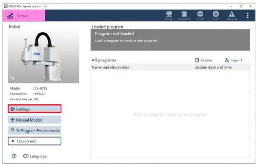
2. Choose "Remote I/O" at [System Settings] - [Controller Configuration] - [Controller device change].
Controller Configuration
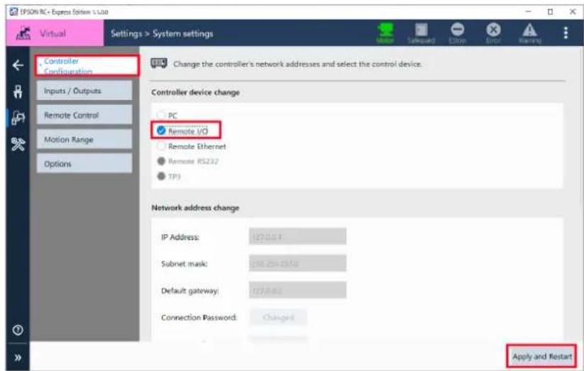
3. Choose Input bit of "Start" and "SelProg1" at [Remote Control] - [Remote Input/Output], and tap the button.
For the details of Remote Input/Output, see the following below: EPSON RC+ User's Guide
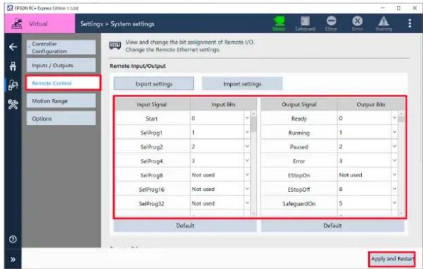
4. Follow the procedure below.
Start to operate program with Remote I/O.
When connected to external equipment such as PLC: After setting the Input bit of "SelProg1" to "ON" from the external equipment, setting the Input bit of "Start" to "ON" to execute the program.
When using Virtual Mode: Follow the steps 5 to 6.
5. Open the Program edit screen, and tap [Remote I/O].
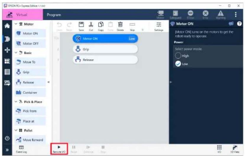
6. When following appeared, adjust the speed limitation and tap the button.
The program waits for execution once.
When you check Force Low Power Mode, the motor will be low power and the speed will be slow regardless of the speed limitation value.
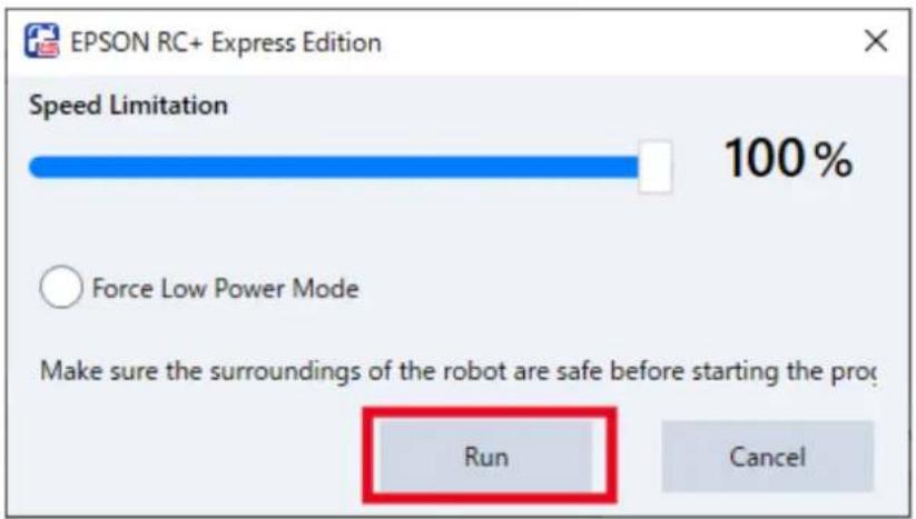
7. Tap [I/O].
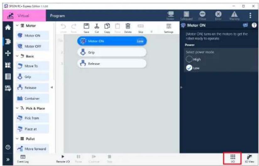
8. Set the Input bit of "Selprog1" to "ON" then set the Input bit of "Start" to "ON".
The program is executed.
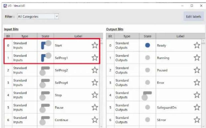
Using Remote Ethernet
Remote Ethernet is to operate a program using remote command from an external device such as PLC connected via Ethernet (TCP/IP).
Operation procedure
1. Tap Home - [Settings] to display setting.
Starting set up for Remote Ethernet.
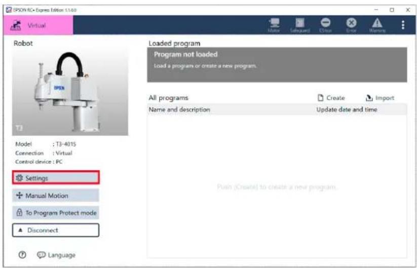
2. Choose "Remote Ethernet" at [System Settings] - [Controller Configuration] - [Controller device change].
Controller Configuration
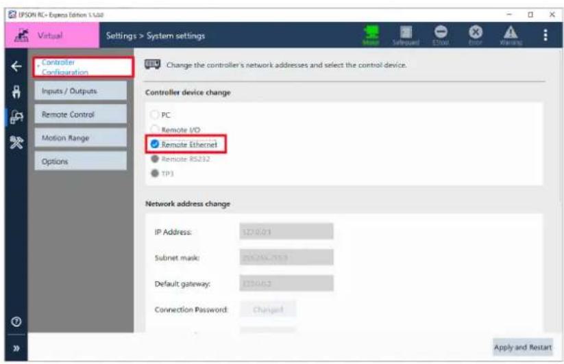
3. Fill each item at the [Remote Control] - [Remote Ethernet], and tap .
For the details of Remote Ethernet, see the following below: EPSON RC+ User's Guide
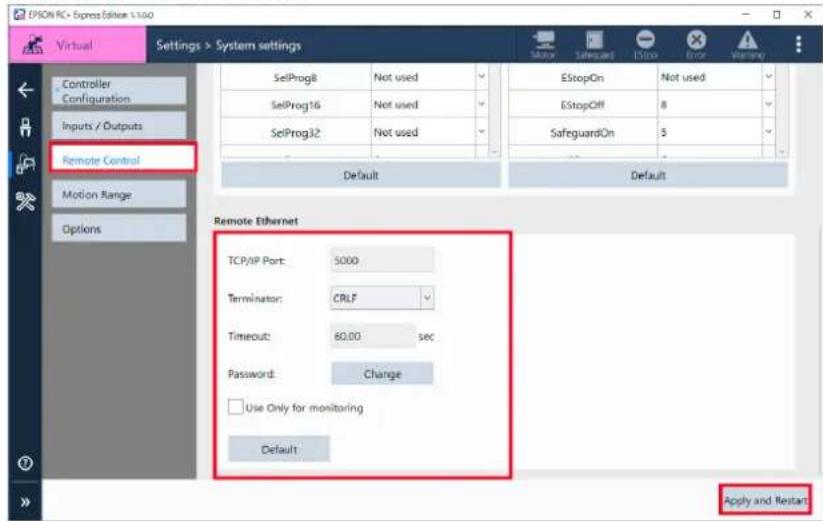
-
Follow the steps below and operate program with Remote Ethernet. When connected to external equipment such as PLC: Executes program to send signals to the robot via Ethernet from external device. When using Virtual Mode: Follow the steps 5 to 6.
-
Open the Program edit screen, and tap [Ethernet].
![EPSON AC+ Express Edition 1.1.0.0 Virtual Program Motor ON Motor OFF Basic Move To Grip Release Container Pick & Place Pick from Place at Pallet Move forward Event Log Ethernet Save Cut Copy Delete Stop Settings Motor ON Grip Release Release [Release] sends a release command to the hand. Motion test I/O 3D View](/content/2026/05/821542/images/82efc1cc0e9f8496e10966262d23d2370f090777ee44424065cfc19306488ea0.jpg)
6. When following appeared, adjust the speed limitation and tap the button.
The program waits for execution once.
When you check Force Low Power Mode, the motor will be low power and the speed will be slow regardless of the speed limitation value.
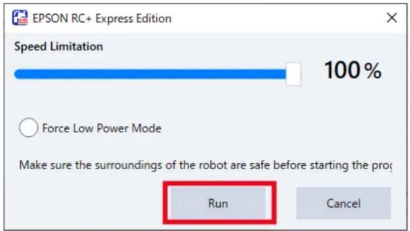
7. Specify "1" to the parameter (function number) from external device such as PLC, and execute the "Start" command.
The program is executed.
Setting I/O Functions
I/O Functions
I/O is a function which communicates with external device via Input/Output terminals installed on the robot Controller.
Followings are supported I/O devices:
| Item Description | |
| Standard I/O | Standard digital I/O of the Controller. |
| Hand I/O (Only T Series) | A Standard digital I/O only for T Series. This is displayed only when Hand I/O is set in robot Controller. |
| Extended I/O | An I/O board added to the Controller to extend standard I/O. Available to add the board which has 24 Inputs and 16 Outputs. T Series Manipulator is not available to add the boards. |
| Fieldbus Slave I/O | An option to add Fieldbus Slave function to the Controller. When using LS-B series, available to add one board that supports Fieldbus Slave. When using T Series, available to add one module that supports Fieldbus Slave.For the details, refer to the following manual:Robot Controller Option Fieldbus I/O |
I/O number assignments are as follows:
- T, VT Series
| I/O | Input Bit No. | Output Bit No. |
| Standard I/O | 0 to 17 | 0 to 11 |
| Hand I/O | 18 to 23 | 12 to 15 |
| Fieldbus I/O | 512 to 2559 | 512 to 2559 |
- RC90 Series (LS Series)
| I/O | Input Bit No. | Output Bit No. |
| Standard I/O | 0 to 23 | 0 to 15 |
| Extended I/O (1st) | 64 to 87 | 64 to 79 |
| Extended I/O (2nd) | 96 to 119 | 96 to 111 |
| Fieldbus I/O | 512 to 2559 | 512 to 2559 |
• RC700-A Series (G, C Series)
| I/O | Input Bit No. | Output Bit No. |
| Standard I/O | 0 to 23 | 0 to 15 |
| Extended I/O (1st) | 64 to 87 | 64 to 79 |
| Extended I/O (2nd) | 96 to 119 | 96 to 111 |
| Extended I/O (3rd) | 128 to 161 | 128 to 143 |
| Extended I/O (4th) | 160 to 183 | 160 to 175 |
| Fieldbus I/O | 512 to 2559 | 512 to 2559 |
• RC700-D Series (GX Series)
| I/O | Input Bit No. | Output Bit No. |
| Standard I/O | 0 to 23 | 0 to 15 |
| Extended I/O (1st) | 64 to 87 | 64 to 79 |
| Extended I/O (2nd) | 96 to 119 | 96 to 111 |
| Extended I/O (3rd) | 128 to 151 | 128 to 143 |
| Extended I/O (4th) | 160 to 183 | 160 to 175 |
| Fieldbus I/O | 512 to 2559 | 512 to 2559 |
For I/O wiring arrangement, refer to the following manual: Manipulator Manual
For setting, adding and checking of Fieldbus, refer to the following manual: Robot Controller Option Fieldbus I/O
Checking for the I/O Setting
At Inputs / Outputs, available to check the status of I/O that installed on the Controller.
When connecting to Virtual Robot, available to change all status of Input Bit and Output Bit at I/O monitor.
To display the Inputs / Outputs screen, tap Home - [Settings] to appear the robot setting screen, and then tap [System Settings] - [Inputs / Outputs].
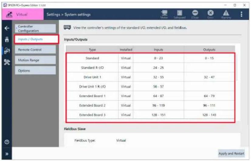
Setting for the I/O
Available to check I/O status or change settings at I/O monitor.
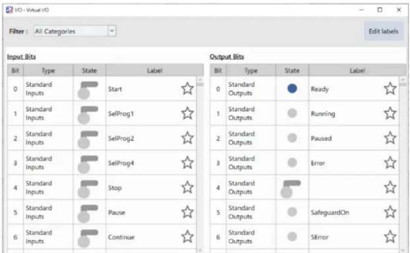

To display I/O monitor, tap the program edit screen or the Jog panel - .
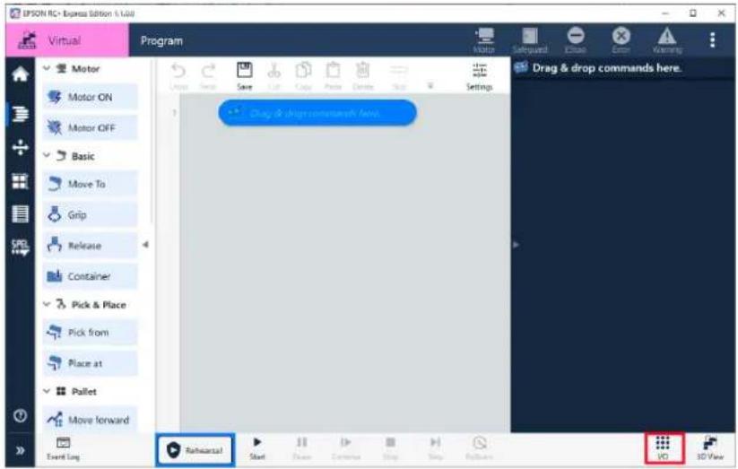
I/O states are as follows:
| Item | Description |
ON, cannot be changed | Not available to change status at I/O monitor. |
OFF, cannot be changed | Not available to change status at I/O monitor. |
ON, can be changed | Available to change status at I/O monitor. |
OFF, can be changed | Available to change status at I/O monitor. |

Not available to change I/O status under the following conditions:
- In emergency stop
- Output bits used in Remote I/O
Tap the
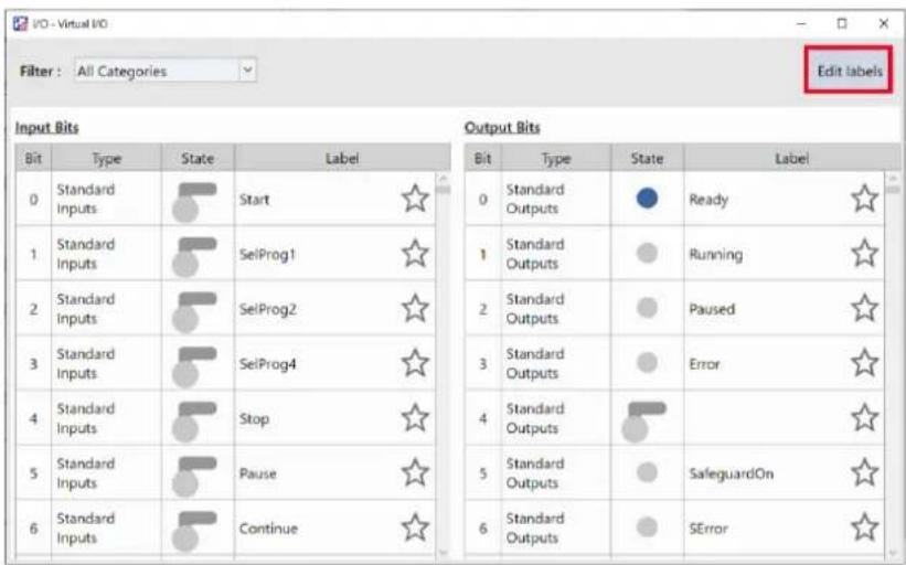

- Available to name labels whatever you like. However, label status information is not transferred when the program is exported to RC+.
- Not available to edit bits used in Remote I/O or Hand I/O.
More Functions
Registering Custom Template
Custom template is to register the program that created by user as a template. Available to register a program exported as a custom template.
Operation procedure
-
Export the program you want to register as a custom template. Exporting
-
Tap Home - [Create].
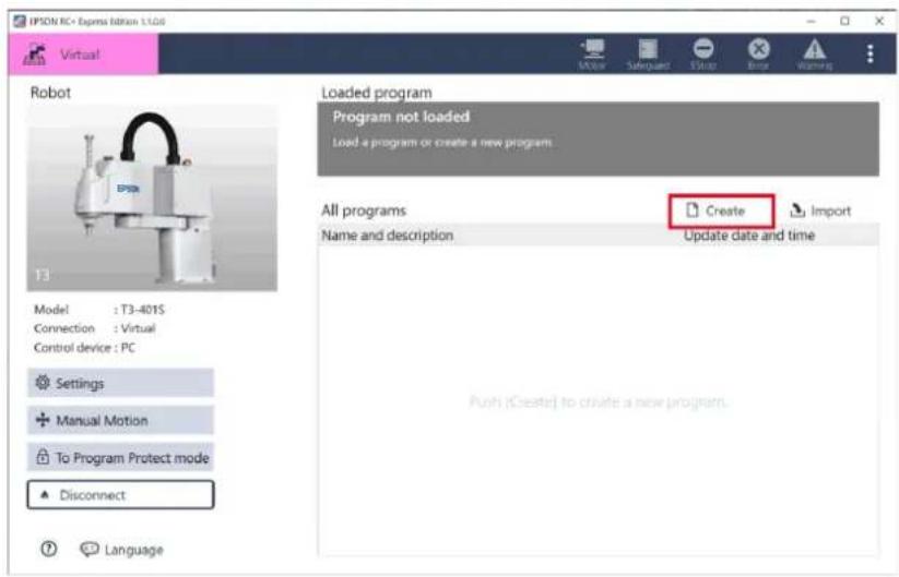
- Select [Import template], and tap the
button and specify the saving destination of exported data, then tap button.
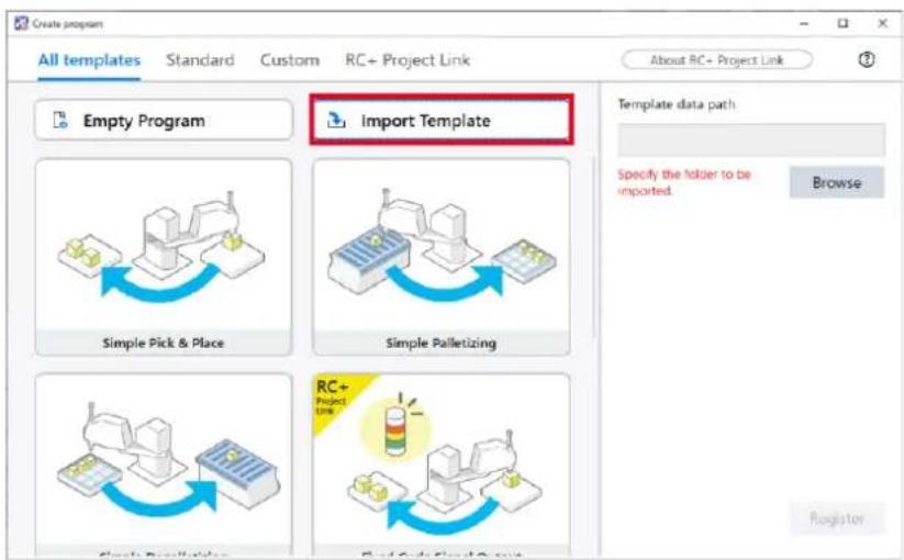
- Enter program name and description and tap the
button.
When not entering program name, it is registered as "Custom" or "Custom_* (number)".
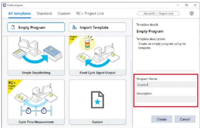

Up to 12 templates can be registered.
Editing custom template
Select custom template and tap to change the name and edit.

It is up to 24 characters.
Deleting custom template
Select custom template and tap to delete them.
Exporting and Importing a Program
Exporting
Exporting is to extract program data from robot and saving it on PC. The saved data can be imported to robot when you needed.
Operation procedure
1. Select the program to export and tap - [Export].
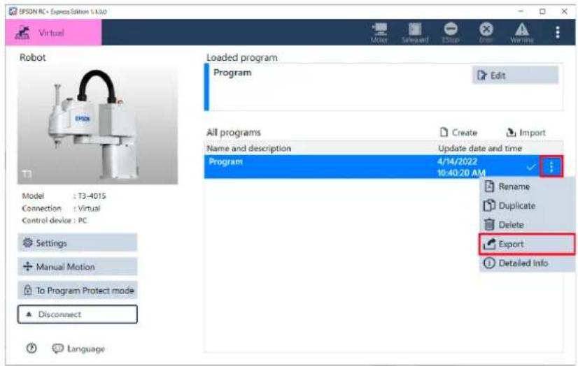
2. Tap the button and specify the saving destination of the program you want to export and tap the button.
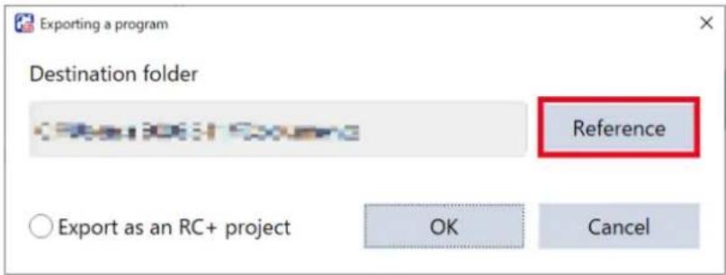

Check in the check box of [Export as an RC+ project] when using the program or RC+.
Exporting Program to RC+
Importing
Importing is to import the exported program to the robot.

If the robot when the program was created is different from the connected robot, a warning given.
To check the robot when the program created, tap - [Detailed Info].
If you edit the program and then save it, the warning disappears because it changes to the robot you are currently connected to.
Operation procedure
1. Tap the button.
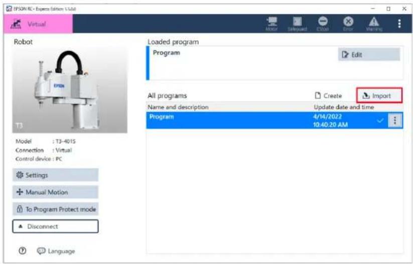
2. Tap the button and specify the saving destination of the program you want to import and tap the button.
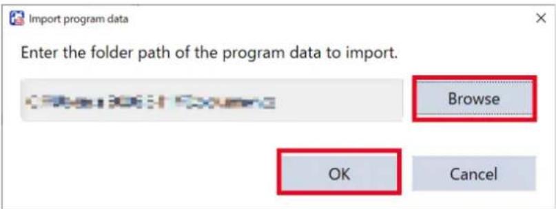

If there already have a program with the same name, you can overwrite it and import it. In case you needed, change the name of the program and then import.
Exporting Program to RC+
Available to export a program created in this software to RC+ and edit it. Check in the check box of [Export as an RC+ project] when exporting a program.
Available to export a program in a form that can be used with RC+. Exporting
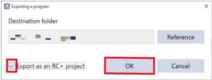

Not available to export when there are unset items in the program and it cannot be converted to a SPEL program.

Programs using RC+ Project Link cannot be exported as a RC+ project.
SPEL+ Code Viewer
Use this feature to display commands of a program in the form converted to SPEL+ programs.
When you select a command on the program edit screen, the SPEL+ function corresponding to that command is highlighted.
Conversely, when you select a SPEL+ function, the command on the program edit screen corresponding to that SPEL+ function is highlighted.
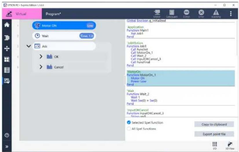
Copy to clipboard
Tap the
Export point file
Tap the
The point file you exported can be imported into RC+ and used.
When the screen to select a destination folder is displayed by tapping the button, select a folder.
Program Protect Mode
You can execute a created program while protecting the program.
For example, when you want to start the program just for checking the robot motion, this mode prevents the program from damaged due to erroneous operation.
Tap the
Tap the

Once you set the program protect mode, your PC is in the mode until you unlock it. Even if you change the connecting Controller, it continues. Be careful not to lose your password.
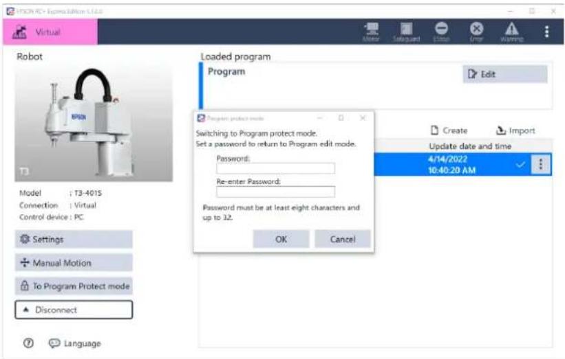
What you can do
- Executing a created program
- Operating a robot by jog operation
- Editing teaching coordinates of a created program
- Editing point files of a created program
- Saving a program
- Using the rollback function
What you cannot do
- Creating a new program at Home screen
- Importing a program
- Adding, deleting, and replacing commands for a created program
RC+ Project Link
Overview of the feature of RC+ Project Link
For RC+ Project Link, by importing SPEL+ project of EPSON RC+ to this software, then you can use variables or functions defined in the project as a command for this software.
This feature is supposed to be used like user create a project using complicated functions on RC+ then use the project easily as a command in EPSON RC+ Express Edition.
Conditions to Use RC+ Project Link
This page describes conditions to use the feature of RC+ Project Link.

This section is intended to be read by users who are familiar with RC+.
Preparations to use the feature of RC+ Project Link
Before using the feature of RC+ Project Link, ready for these.
- Make sure your controller firmware version is following. RC90/RC700 series 7.5.3.0 or later T/T-B/VT series 7.5.53.0 or later
- Before using the feature of RC+ Project Link, prepare following.
- Install 7.5.3 or later version of EPSON RC+ on a PC installed RC+ EE. Installing the Software Installing (From DVD Drive), Installing (From USB, Shared Folder)
- Enable "RC+ Express Advanced". How to enable: Options
- Start EPSON RC+ and setup destination.
- When connecting robot using Ethernet connection, create a connection of the robot. (Its no needed If you connect using USB.)
- When connecting robot using virtual, prepare virtual controller for build of RC+ EE program.
- OFF the [Work Offline] in settings of destination.
Restrictions when option is disabled
Followings are restrictions when "RC+ Express Advanced" is disabled.
- The continuous operating time of the program using RC + Project Link is 10 minutes.
When you are using a virtual controller, the restriction depends on the controllers.
Executing a Program to Check for Problems
- The program using RC+ Project Link can be operated only on RC+ EE.
You cannot do Remote execution (Remote I/O, Remote Ether) in Auto mode.
Creating RC+ Project
Interface Definition File RCEE Exports.prg
What is RCEE_Exports.prg

This section is intended to be read by users who are familiar with RC+.
Create a project which has functions or variables that you want to call, on RC+. At that time, the program file that acts as an intermediary between RC+ and RC+ EE is RCEE_Exports.prg.
Define the functions and variables referenced from RC+ EE in the interface definition file RCEE_Exports.prg.
By utilizing RCEE_Exports.prg, you can use functions of RC+ program on RC+ EE, without affecting the existing program of RC+ or disclosing the contents.
Based on the existing RC+ project, create RCEE_Exports.prg with following steps below.
- Open a project on RC+ you want to import to the RC+ EE.
- Add newly interface Definition File RCEE Exports.prg to the project. (newly add a program file named RCEE_Exports.prg)
- Write the functions or variables you want to call from RCEE to the RCEE_Exports.prg.
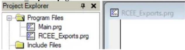
How to Write RCEE_Exports.prg
Declare Variable
When declaring Global variable inside the RCEE_Exports.prg, it will be able to be referred from RC+ EE. (Variables that are not declared Global cannot be referenced from RC+ EE.)
For the variable type, any types that can be declared with SPEL+ is available. However, array is not supported.
It is possible to change how to display on RC+ EE by writing comments following below rules just before declaring variables.
-
Syntax:‘
How it's displayed on RC+ EE:
When displaying the variable name, a string specified as a [variable name] will be used.
-
Syntax: "
How it's displayed on RC+ EE:
When displaying the description of variable, a string specified as [description string]
Definition of function
Define the function inside the RCEE_Exports.prg the way it has no return values and arguments.
It is possible to change how to display on RC+ EE by writing comments following below rules just before declaring function.
-
Syntax: "
How it's displayed on RC+ EE:
Displayed as a command name.
Command name can be changed manually when importing function on RC+EE.
-
Syntax: '
How it's displayed on RC+ EE:
Displayed as a description of command at command property.
Also, by adding comments following rules below, relates Global variable to function and it is possible to use as a command property or return values.
- tag
Syntax: "[description
string]
[variable]: Write a defined Global variable you want to use as an argument.
[Description string]: Write a description of command property.
How it's displayed on RC+ EE:
The specified variable is displayed as a property item for the command.
[Description string] is displayed for description of property item.
-
Syntax: "
[variable]: Write a defined Global variable.
[Description string]: Write a description of return value for command.
How it's displayed on RC+ EE:
Displayed as a description of command that [variable] is return value at command property.
[Description string] is displayed for description of return value.

Return tag is notification for RC+ EE user the variables that store the execution results.
The creator of the function should not mistake the variable for the value that represents the execution result.
Samples of RCEE\_Exports.prg
Following is a sample of RCEE_Exports.prg.
By writing variable or function like following below, it is possible to referred on RC + EE.
'
'
Global Integer g_LeftHSValue
'
'
Global Integer g_RightHSValue
'
'
Global Integer g_ResultValue
'
'enter a value.
'enter a number to add.
'
Function DoAdd
g_ResultValue = g_LeftHSValue + g_RightHSValue
Fend
Restriction When Creating RC+ Project
To use RC+ Project Link, you need to be careful about following contents when creating RC+ Project.
Correct your program if necessary.
- File
- Do not encrypt RCEE_Exports.prg
Do not encrypt RCEE_Exports.prg because RC+ EE interpret definition of functions and variable.
- Function name
- Do not define Function Main1
Main1 is execute function for RC+EE.
Do not use it for RC+ project to avoid duplication.
- Do not use "RCEE_" to the head of the name.
Do not use it for RC+ project because "RCEE_" is used as a prefix of inside function of RC+ EE.
- Using point file
- Use just one point file.
To avoid conflict with RC+ EE point definition and to operate robot safely, number of point file can be imported from RC+ project is just one when importing RC+ project on RC+ EE.
If you use the Vision Guide calibration it may automatically generate a point file. It does not have to be merged to the point file to import.

- Use point number 500 to 999.
Point number 0 to 499 will be used for RC+ EE.
To avoid conflict with RC+ EE point definition, use point number 500 or after for RC+ project.
- For the point used in the RC+ EE program, set the local coordinate system (Local field) to 0.
Points with numbers other than "0" set in the local coordinate system cannot be selected in the RC+ EE program.
- When with the option of additional axis, the points used in the RC+ EE program make the S and T values empty (undefined).
Points a value is defined for either S or T cannot be selected in the RC+ EE program.
- When you specify a flag that your robot does not support, an error occurs at execution.
(For example, specifying "1" for J1Flag while using C4 series robot.)
- Using pallet
- Use the numbers 8 to 15 for pallet definition.
Pallet 0 to 7 will be used for RC+ EE.
When using pallet on RC+ project, use pallet 8 to 15 to avoid conflict with RC+ EE.
Refer to "Using robot parameters on RC + " in the below.
- Using Tool
- Do not change the settings of Tool1 For RC+ EE, Tool 1 is defined at hand setting and it used for program. Do not change Tool 1.
- Be careful for selecting Tool. If you changed Tool kinetically on RC+ program, it affects operation of RC+ EE program. In the property of RC+ function, set [Allow to change tool number.] correctly and prevent unintentional Tool changes. Refer to “Using robot parameters on RC+” in the below.
- Using robot parameters on RC+
Robot parameters will not be imported on RC+ EE.
Therefore, set the robot parameters expressly in the RC+ program.
Robot parameters is a configuration set in [Robot Manager] on RC+. Example: Palle definition, Tool settings, etc.
·SPEL+ Command
- Do not use an unsupported command
RC+ EE do not support following SPEL+ commands execution. Do not use these SPEL+ commands. - Examples of command uses RC+ function: RunDialog, SimGet
- Examples of command related to parts maintenance: HealthCtrlInfo
- Command that is only supported executing on command window Example: WorkQue List, Brake
- Examples of command requires entering from command window Input, Line Input
- Examples of command related to OS restart or log in. Shutdown, LogIn
For more details, refer to List of SPEL+ Command Availability in RC+ Project Link.
- Be careful for using command that interact with RC+ EE program
- Arch
If you changed Arch kinetically on RC+ program, it affects operation of RC+ EE program. - Speed/Accel/SpeedS/AccelS
In the RC+ EE program, speed is set by these commands for each command to operate the robot arm.
When operating robot arm in the RC+ function, be sure to set these each time within that function.
- Unsupported functions
- Native DLL Calling native DLL is not supported.
- Vision calibration Operate Vision calibration on RC+.
- PC Vision function When using vision function, use CV2.
Setup for RC+ and Building the Project
RC+ projects to be imported in RC+ EE must be possible to be built in RC+ on the same PC as RC+ EE.

This section is intended to be read by users who import RC+ project to RC+ EE.
Preparing destination when build a program
RC+ EE calls RC+ when it builds a program to which RC+ project is imported.
Therefore, appropriate connecting destination needs to be prepared in [PC to Controller Communications Command] on RC+.
- Connecting robot by using USB on RC+ EE
RC+ called internally also uses a USB connection.
Destination doesn't need to be prepared beforehand on RC+ EE.
- Connecting robot by using Ethernet on RC+ EE
RC+ called internally also connects to the connection destination with the same IP address as RC+ EE via Ethernet.
Prepare a destination as same IP address as RC+ EE in [PC to Controller Communications Command] on RC+.
- Connecting to virtual robot on RC+EE
When building a program on RC+ EE, select the virtual controller to be used from the virtual controllers registered in the RC+ connection.
Prepare a destination to use for RC+ EE in [PC to Controller Communications Command] on RC+ beforehand.

When using Vision Guide in RC+ project, be sure to configure camera setting. However, you cannot use virtual cameras.
Preparing RC+ Project
Connect to the destinations prepared above, and check that RC+ project can build without any problems on RC+.
OFF the [Work Offline] in settings of destination.
When importing RC+ projects created by other PC and using PC with connecting to the other controller, configure environment settings of RC+ properly and check that the RC+ project builds correctly that you want to.
Importing RC+ Project on RC+ EE
This page describes how to import RC+ Project on RC+ EE.
Setup procedure
1. Tap [RC+ Project Link] button.
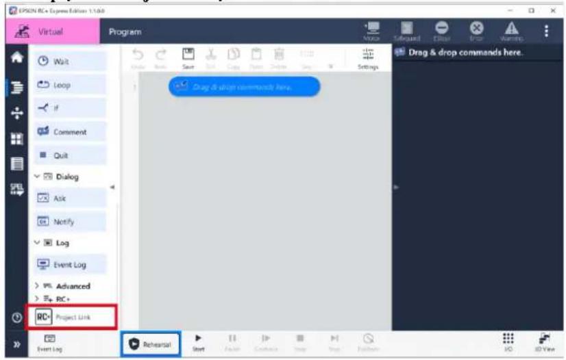
2. Tap [specify project...] button.
Select a project to import.
- You can import only one project.
- You can import only one point file in a project.
![EPSON RC+ Express - Tap [specify project...] button. - 1](/content/2026/05/821542/images/02522c3b59926859215c8268a636682db47d285ab8791dd4d34d77d567e19da0.jpg)
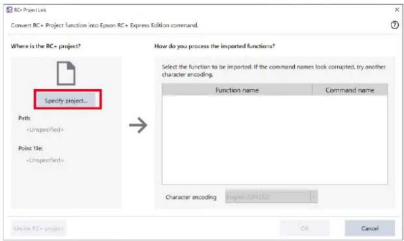
3. Check in the check box of function to import as a command.
A list of functions of project which selected in step 3 will be displayed on the right side of the screen.
Command name can be changed.

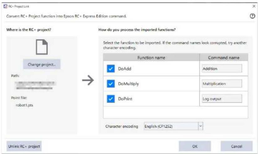
4. Tap [OK] button.
Importing RC+ project is all done.
Imported commands added to command area and variable can be used in the project.
Creating a Program Using Imported Commands
At program edit screen, tap to add the command imported using RC+ Project Link and create a program.
Set the property of command like other normal commands.
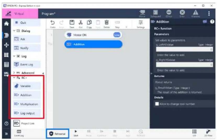
Executing a Program Using RC+ Project Link
Setup procedure
1. Tap [Start] button to start the program.
At the first time of executing program takes a lot of time because of calling RC+. Check that communication cable is connected properly. If the connected is lost, the program may be damaged.
![EPSON RC+ Express - Tap [Start] button to start the program. - 1](/content/2026/05/821542/images/b952ab9052cebc79f62975e0baa42e3f24bfe702a9cdedb5558451137652625a.jpg)
• To prepare executing program, the destination that registered on RC+ will be used. When connected to a virtual controller, a dialog to select the destination will be displayed.
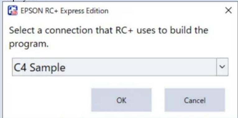
- Select the destination set in RC+.
- When RC+ project is saved in the virtual controller of the destination, a massage is displayed to check the overwrite.
- When an error message is displayed while building, refer to the following.
Troubles when using RC+ Project Link
However, if you cancel the execution at any time before the program runs, you will also get an error message.
In this case, you need to do something.
2. Tap [Run] at dialog to check for run.
As same as when not using RC+ Project Link, tap [Run] button and start the program.
Trouble Shooting
The icon at the top of the screen lights up
Status icon upper part of the screen

natural_image
Row of five gray icons on a dark blue background: monitor, door, minus sign, cross, and warning triangle (no text or symbols)will lights up when
an error occurred or informing you a message.
Solution:
Tap the icon to check the message and how to reset it. For the meaning of each icon, see the following below Status Bar
Powered off accidentally while editing program
When powered off accidentally while editing program, [Program recovery] is displayed at Home screen.
Solution:
If you want to recover the program, tap "Recover", and if you don't need the program, tap "Delete".
If you want to save the data, tap "Save to local".
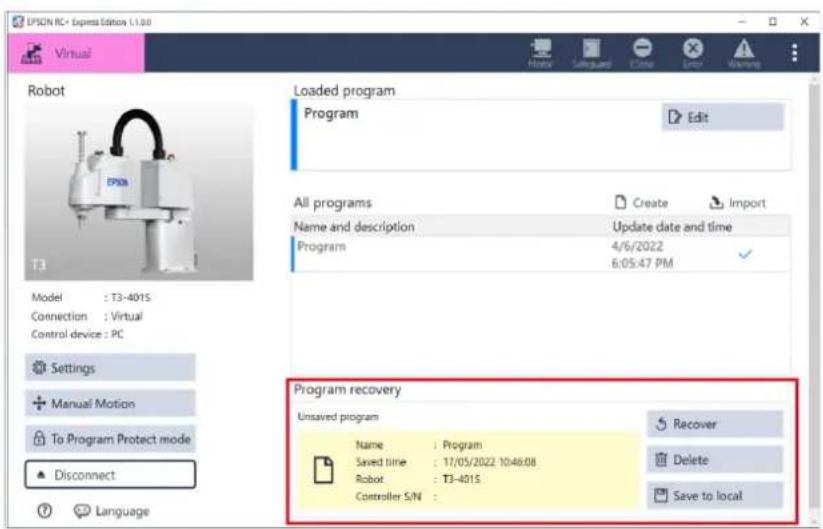
Connecting to robot failed
Failed in connecting to robot for any of the following reasons. Check and solve them.
- No robot is added to the controller.
Solution:
Register a Robot at RC+. Not available to register a robot by this software. RC+ EPSON RC+ User's Guide 10.1.1 Adding a standard robot
- Controller is executing tasks.
Solution:
If you are using Remote I/O or Remote Ethernet, stop executing the task. After stopped tasks, it is possible to connect by programming mode.
- Controller firmware version is not matching to this software.
Solution:
Update your version of the controller firmware.
- The setting of IP address of the network is wrong.
Solution:
Check your setting of IP address of the network and set it again. Controller Configuration
Check your setting of IP address of the controller and set it again. RC+ User's Guide 14.1.2 IP Address.
- Your Controller preference is valid in “not to connect to EPSON RC+ Express Edition”.
Solution:
Change to invalid at RC+. EPSON RC+ User's Guide - 5.12.2 [System Configuration] Command (Setup Menu)
I want operation speed of the robot to move faster
The robot moves slowly for any of the following reasons: Check and solve them.
Solution:
If you want to operate the robot more faster, change the speed of each path type in [Settings].
If it still does not speed up, the Power mode of the “Motor on” command may be “Low”.
Change to "High" to speed up.
[Arm reached the limit of motion range.] message showed up
The message will show up when you are moving robot out of the limit of motion range or when robot is Singular Postures.
Solution:
When you received this message while operating Jog & Teach or after tapped
Troubles when using RC+ Project Link
Errors that are specific to the RC+ Project Link function may occur.
Modify the settings of RC+ project and/or RC+ to correct the error.
If you have modified the program for the RC+ project, re-import the modified RC+ project.
An error occurs when importing a program
When the message [Specify the appropriate location.] appears after you specified the RC+ project to be imported, the project configuration is probably incomplete.
Solution: Check whether the RC+ project contains RCEE_Exports.prg.
What is RCEE_Exports.prg
An error occurs when starting the RC+ project
When you try to run a program by tapping the
- The program of the RC+ project is incomplete
Solution: Build the project with RC+ and correct the error.
- Function Main1 is defined in the RC+ project
Solution: Modify not to use Main1 in the RC+ project.
- A function that starts with "RCEE_" is defined in the RC+ project
Solution: Modify not to use functions that start with "RCEE_" in the RC+ project.
- The camera to be connected is not configured correctly (when using Vision Guide)
Solution: Use RC+ to set up correctly the camera to be connected. However, you cannot use virtual cameras.
An error occurs when a program is running
An error that occurs when a program is running can be caused by:
- An unsupported SPEL+ command is being used
Solution: Modify the program to configure it with the SPEL+ commands that are supported by RC+EE.
Restriction When Creating RC+ Project
- The robot parameter values set in the RC+ robot manager is referred by the function imported by RC+EE
Solution: When there is a part which the function imported by RC+EE refers to the robot parameters on RC+, set expressly the part in the program.
Restriction When Creating RC+ Project
Robot is in singular postures
A singular posture is a posture that prevents the robot from moving even though the robot is in the motion area.
There are several singular postures for a 6-axis robot.
Returning from singular postures
- When the robot is operated in a mode that performs linear motion, such as World mode or Tool mode, move the robot in Joint mode to return from singular postures easily.
Avoiding singular postures by setting environments
- You can configure the motion to avoid singular postures.
- A posture to move quickly to non-singular postures can be set to “Basic posture”.
Refer to the following to set the both settings.
Status Bar
The robot stops even if the posture to avoid singular postures is set
The robot can be stopped due to an acceleration error or a motion range error. If the singular posture causes these errors, the singular posture pop-up appears. Check the pop-up and solve the error.
Tap the
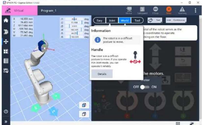
Failed in Rollback
You can not use the rollback function in the following conditions. Check and solve them.
- The control device is set to other than "PC"
Solution:
Set the control device to "PC" in [System Settings].
Rollback is not available for non-PC control devices such as PLC.
Controller Configuration
- Jog operation was performed after the program has stopped or an error has occurred
Solution:
If you perform a jog operation after the program has stopped, you cannot use the rollback function.
Perform the rollback function before performing the Jog operation.
- Loading other programs
Solution:
When you have loaded a program, you cannot use the rollback function to the previously edited program.
When using the rollback function with the current program, do not load other programs.
- Operated robot in other than main task using RC+ Project Link.
(When you can do rollback but robot moves unexpectedly.)
Solution:
Do the operation of robot using main task.

The movement of the robot is recorded only during the operation of the main task, and the movements other than the main task are not recorded.
It is the same thing when you moved the robot by the hand using SFREE.
If the robot moves unexpectedly when you did rollback, confirm that movement is during the main task operation.
Settings
Robot Settings
In the setting tab, you can set of system, hand and maintenance.
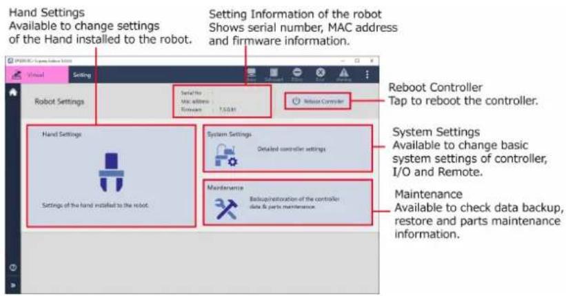

- A warning is given if the setting is different from the recommended value in system settings. Available to change setting to tap the warning.
- A warning is given when the recommended replacement period for controller consumable has passed. Available to change setting to tap the warning. About Parts Consumption Information
To display setting tab, tap Home - [Settings].
![EPSON RC - Express Edition 6.1.00 Virtual Robot Model : T3-4015 Connection : Virtual Control device : PC Settings Manual Motion To Program Protect mode Disconnect Language Loaded program Program not loaded Load a program or create a new program. All programs Name and description Create Import Update date and time Push [Create] to Create a new program.](/content/2026/05/821542/images/e17dab4d1ca2fa863a6b095f900d7f35539f642f07241e5d5e27abea0b14ffc5.jpg)
System Settings
Controller Configuration
It is possible to set followings for the Controller.
To display General tab, tap Settings - [System Settings] - [Controller Configuration].
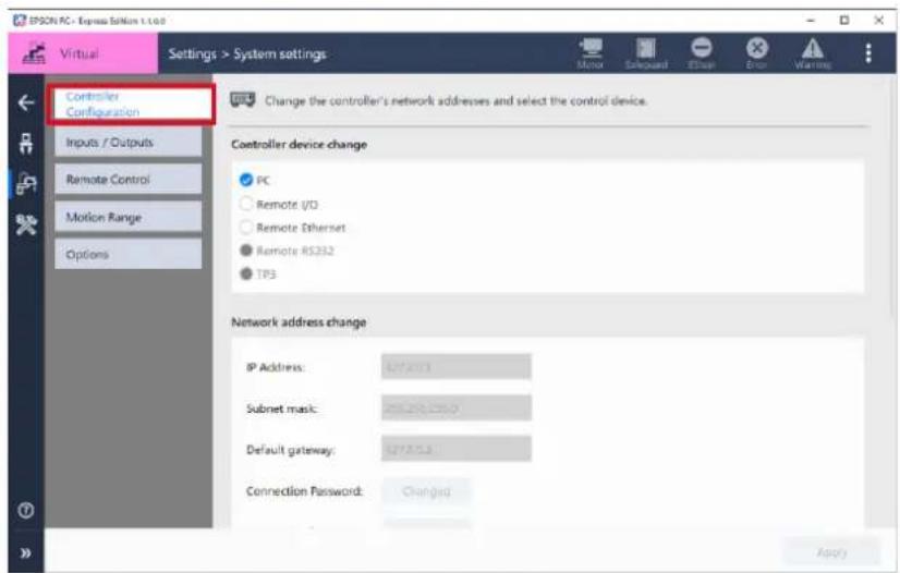
Controller device setting
Set up the device that control program of start or stop with Auto mode. After changed the device, tap the
| Item | Description |
| PC | Start/End program by USB or PC with Ethernet connection. |
| Remote I/O | Start/End program from I/O Input of external equipment. |
| Remote Ethernet | Start/End program by remote command from external equipment with Ethernet connection. |
Network address change
Set up for Controller network.
After changed the device, tap the
Followings are devices you can select.
| Item | Description |
| IP Address | Set up for IP Address of LAN (Ethernet connection) port. Set the IP Address on the same subnet as the operating terminal. |
| Subnet mask | Setup for Subnet mask of LAN (Ethernet connection) port. Match the subnet mask with the subnet mask used in the network. |
| Default gateway | Setup for the default gateway of LAN (Ethernet connection) port. This is needed when accessing to controller from outside of local network. |
| Connection Password | When using global IP address in controller, a connection password (more than 8 characters) setting is needed. |
| TP password | Set up for password of TP maintenance mode. Set TP password with 16 characters or less. When connecting to virtual controller, password can not be changed. |
Environment Settings
You can check Controller environment setting. In default setting, following is already checked:
To reset to default value, tap the
- Outputs off during emergency stop
- Walk stops for output commands
- Include project files when status exported
- Auto safeguard position recovery
- Independent mode
- Clear globals when MainXX function started
- Motor off when Enable switch off in Teach Mode
- Check XYLim during path and pulse motion
For details of each item, refer to the following:
EPSON RC+ User's Guide
Inputs / Outputs
It is possible to check I/O number assignment that connected to the controller and change settings of Fieldbus Slave.
To display the Inputs/Outputs tab, tap Settings - [System Settings] - [Inputs/Outputs].
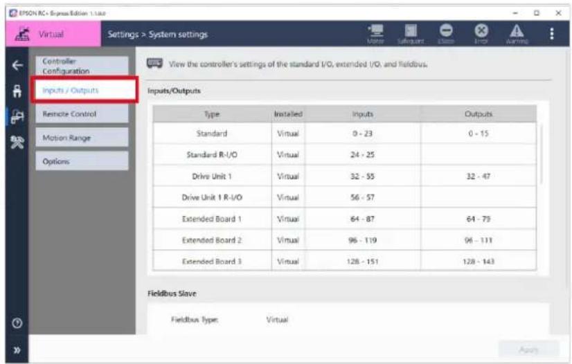
Inputs / Outputs
You can check current status and bits assigned to the Input / Output. If you want to use Standard I/O, Hand I/O or Extended I/O, refer to the following: Manipulator Manual

When connected to the virtual robot, [Installed] is indicated as "Virtual".
Fieldbus Slave
Indicates information of Fieldbus that installed in the controller, and it is possible to change the value.
For details of Fieldbus, refer to the following: Robot Controller Option Fieldbus I/O Manual

The displayed items differ depending on the type of fieldbus.
Remote Control
Available to make the necessary settings when using remote I/O or Remote Ethernet as a control device.
To display Remote Control tab, tap Settings - [System Settings] - [Remote Control].
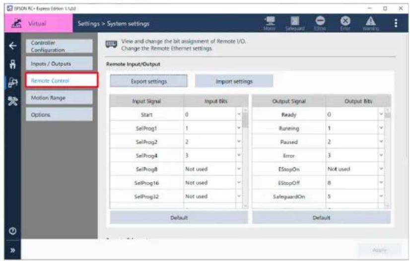
Remote Input/Output
Indicates bits assigned to each signal when Input/Output of remote.
Following shows each button functions:
| Item Description | |
| Default | Reflects the default value on all Input / Output bits.Following shows options:- Clear AllApplies “Not used” to all items. In this case, all I/O bits can be used as normal Inputs/Outputs.- Standard I/O- Extended I/O- Fieldbus Slave I/O |
| Export settings | Available to save bit assignments of Remote Input / Output on PC.Specify the save location and tapbutton.The default file name is “Remotes (Date).dat”. |
| Import settings | You can load a file that saves bit assignments for remote Input / Output and reflect them in the current settings.Specify the folder where the data you want to import is saved, and tap thebutton. |
Remote Ethernet
Set up Remote Ethernet. If you want to reset to default value, tap the
Set up Remote Ethernet.
| Item | Description |
| TCP / IP Port | Port settings of TCP/IP communication. You can use number 0 to 65535. |
| Terminator | Settings for terminator. You can choose from CRLF, CR and LF. |
| Timeout | Settings of Timeout. You can enter real number up to 4 digits. |
| Password | Changes the view. It is possible to change Password Tap thebutton and enter with half-width characters.You can enter up to 16 characters. |
| Use Only for monitoring | If checked, it can be used as a monitor. |
Motion Range
Available to set XYZLimits Setting and Range Setting.
To display Motion Range tab, tap Settings - [System Settings] - [Motion Range].
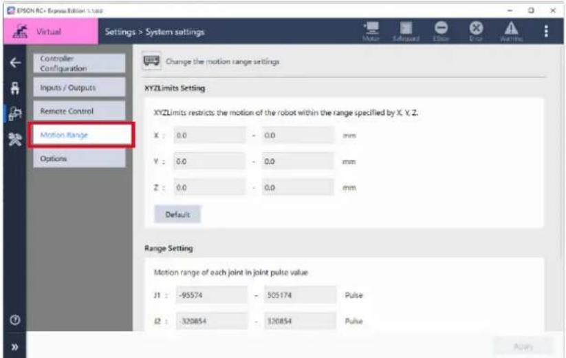
XYZLimits Setting
In the world coordinate system, you can set the limits that the robot can operate in each coordinate system.
Enter the upper limit and lower limit position of X, Y and Z axis, and set the XYZLimits.
For the details of XYZLimits, refer to the following:
SPEL+ Language Reference

Tap
Range Setting
Enter lower limit of each joint axis and the value of encoder pulse value of upper limit and then set XYZLimits of each joint.
For the details of Range Setting, refer to the following:
SPEL+ Language Reference

Tap
Refer to the following:
Manipulator Manual
Options
This page describes the setting to enable/disable the controller option "RC+Express Advanced".
To display the screen of controller option, tap [Settings] - [System Settings] - [Options].

The "RC+ Express Advanced" option can also be set from the EPSON RC+ options screen.
The followings are steps to enable the option.
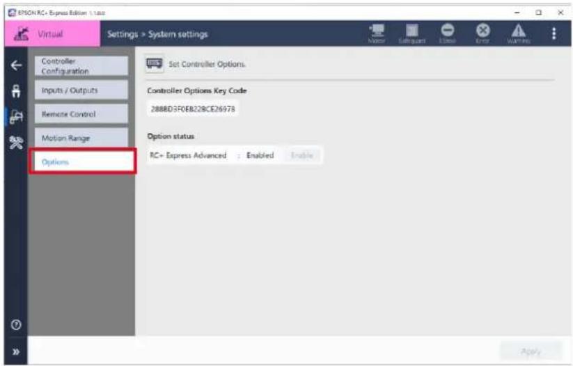
Setup procedure
-
Tap the
button. -
When the dialog to enter the option activation key code, enter the key code.
-
Tap the
button.
Hand Settings
General
Available to set the hand I/O and operation parameters.
To display General tab, tap Settings - [Hand Settings] - [General].
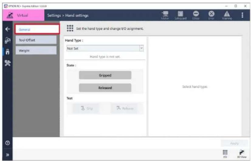
Operation procedure
1. Select a hand from pull down [Hand Type :].
Shows kinds of Hand supported in controller.
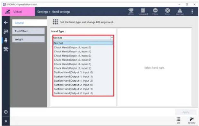
2. Set the I/O when gripping / releasing a work, and tap button.
The setting items differ depending on the type of hand selected.

- After changed the kinds of hand, I/O settings on the right will be cleared.
- After changed hand, [Test] is not available until tap
button.
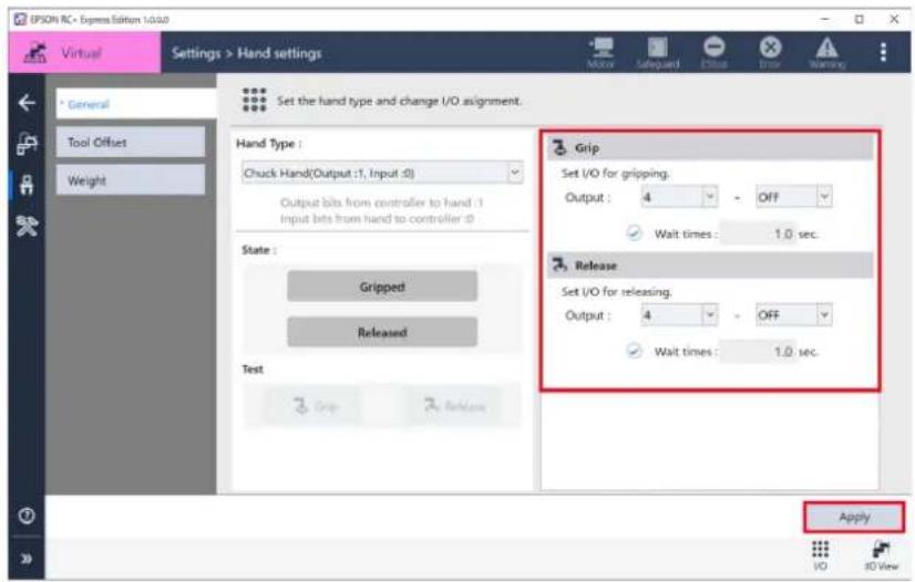
3. Tap Grip / Release and test the operation.
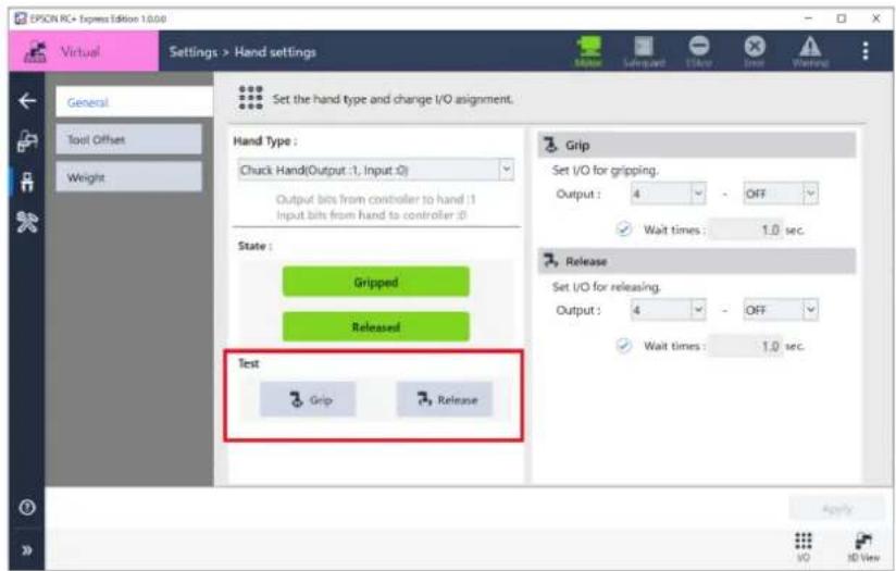
Tool Offset
Tool position is a distance from robot arm tip to holding a work.
Setting the tool position in advance is convenient because even if you change hands, you can use the same program simply by changing the tool position.
Available to change indicator of current coordinate of the robot and change the base of point definition. To operate the hand correctly, enter manually X, Y, Z, U, V, W values or input the value by using,
The wizard can only enter X, Y, Z, U values. V and W value need to be entered by manually.
Example:
When set up the finger tip (gripping point) of the chuck hand on a 6-axis robot:
Offset the gripping point of the attached hand from the center of the flange surface as follows:
Y-axis direction: 50 mm
Z-axis direction: 120 mm
If, in addition to this, the hand is attached with a -90 degree rotation around the Z-axis:
Set the Tool 2 coordinate system as follows.
X: 0, Y: 50 mm, Z: 120 mm, U: -90 mm, V: 0, W: 0
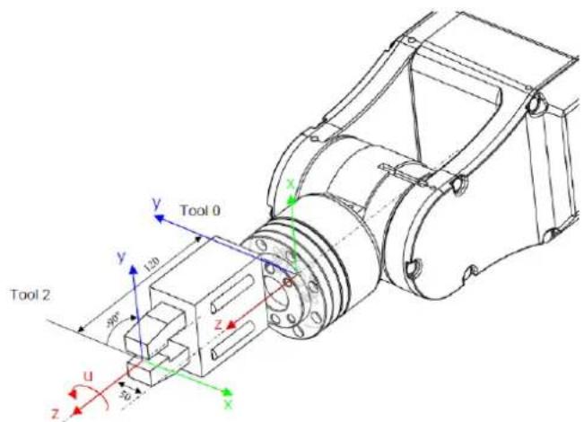
To display Tool Offset tab, tap Settings - [Hand Settings] - [Tool Offset].
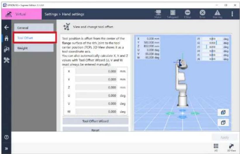
To enter tool position, follow either way to enter the value manually or to input the value by using wizard.
When entering the value manually, enter them manually and tap
When using wizard, tap
Operation procedure
1. Tap [Tool Offset Wizard].
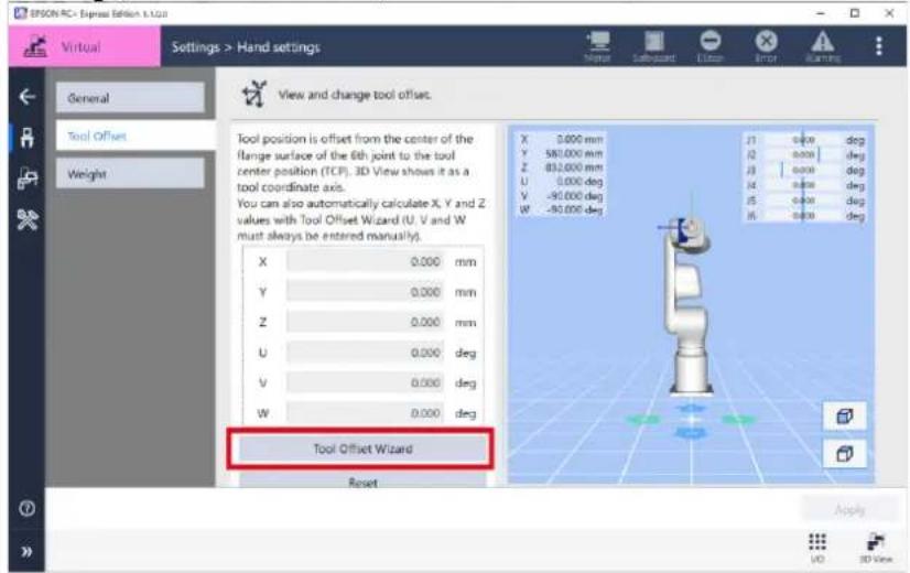
- Teach 3 to 5 points with changing the direction of the hand to based point at the same XYZ position.
Available to check the motion of the robot when connected to the virtual robot.
Operating Robot
V and W value need to be entered by manually. Go back to step 1, and enter the value.

Calculating values of tool X, Y, Z direction, from the taught point.
To calculate with maximum accuracy, you need to teach three to five base points so that the X, Y, Z position is the same and different robot posture.
After changed the robot posture by rotating U, V, W for each base points, jog X, Y, Z so that base points and tool tip is matched.
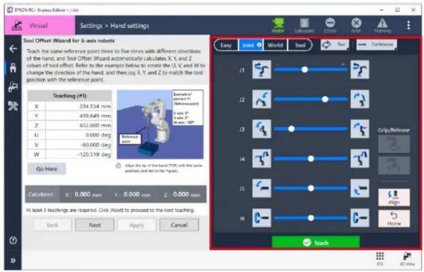
3.Tap
- Tap the
button.
Changes are applied and tool setting is complete.
The arrow indicates tool position will change on the 3D view.
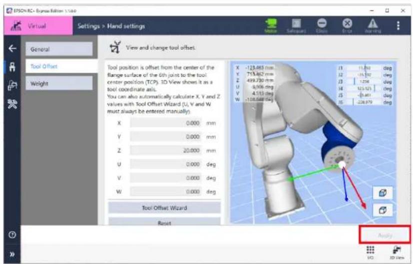
Weight
Available to set hand weight and its details.
To display setting tab, tap Settings - [Hand Settings] - [Weight].
For the details, see below.
Manipulator Manual
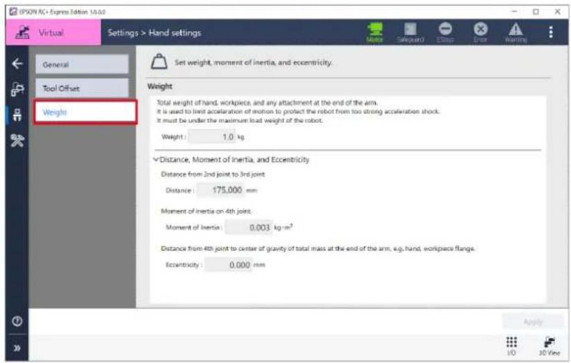
Weight
Displays Hand weight set in controller.
Distance, Moment of Inertia, and Eccentricity
Tap to display weight set in controller. When changing each item, input the value and tap
Language Settings
Available to change language in this software.
To change, select connecting display or Home - [Language].
When the dialog appeared, follow the steps to change language.
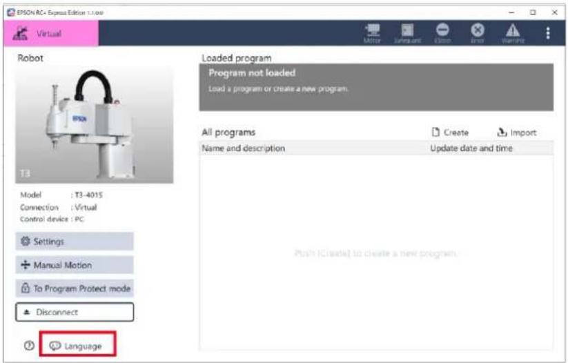
This software support following languages, however available languages are different depends on OS of your PC.
- Japanese
- English
- French
- German
- Simplified Chinese
- Traditional Chinese
Maintenance
Backup
Available to back up of the controller data
The backed up data can be restored to robot in needed. Useful when copying the settings of current connecting robot to another robot.
Tap display Backup tab, tap Settings - [Maintenance] - [Backup].
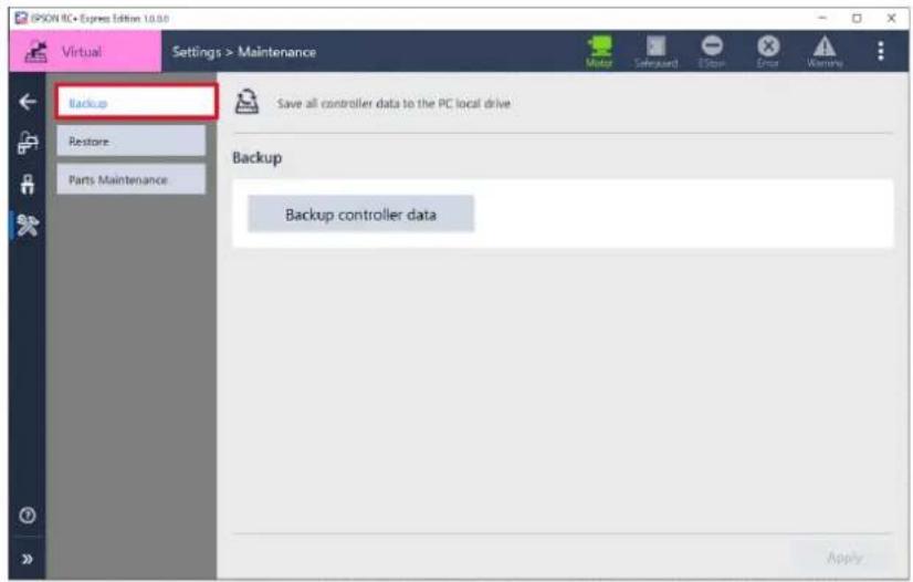
Operation procedure
- Tap
.
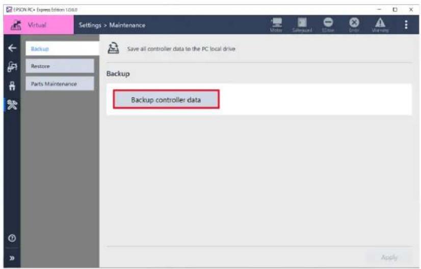
- When following appeared, tap
button.
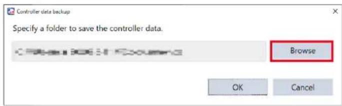
-
Select the folder where back up data saved and then tap
button. -
Check the contents of indication, tap
button.
Summary of the backup data:
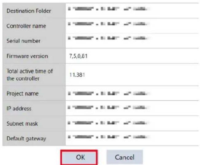
- When following appeared, tap
button.
Restore
Restores the controller data backed up on the PC.
Tap Setting - [Maintenance] - [Restore].
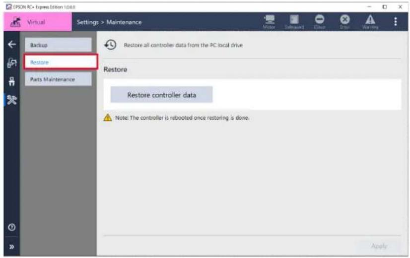
Operation procedure
1. Tap .
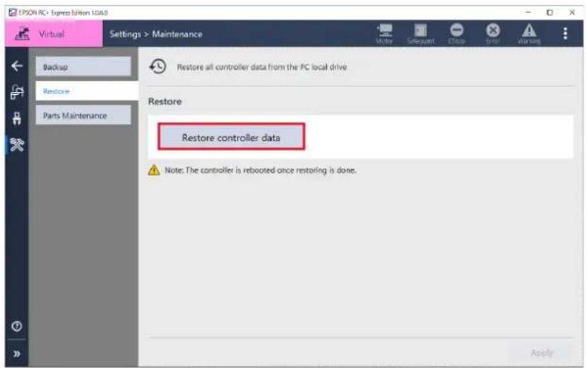
- When following appeared, tap
button.
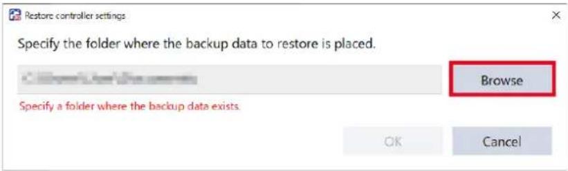
- Select the folder where back up data saved and then tap
button. - Check the contents of indication, tap
button.
The controller starts rebooting. Disconnected to this software and automatically reconnected to this software after rebooting.
- When following appeared after rebooting, tap
button.
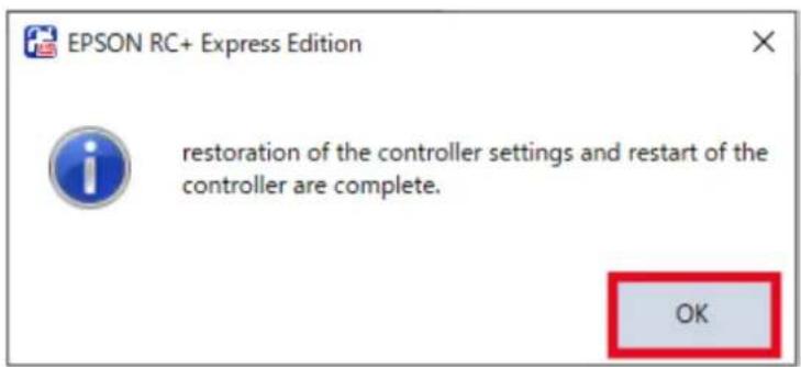
Parts Maintenance
About Parts Consumption Information
Go check to the Parts Maintenance tab if you want to know about replacement time of consumption parts or remaining rate.
Indicates Parts consumption information got from the controller at the Parts
Maintenance tab. Following shows parts needs to be replacement:
- Battery for controller
- Battery for robot
- Grease up
- Timing belt
- Motor
- Reduction gear unit
- Ball screw spline unit
To display Parts Maintenance tab, tap Setting - [Maintenance] - [Parts Maintenance].
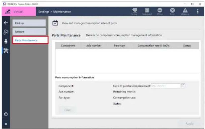

- Parts consumption information cannot be changed or check when connecting to virtual controller or [Enable robot maintenance data] is "OFF" in System settings - Environment setting.
- Not available to check information when the parts consumption information is disabled, even if connected to actual controller.
- A warning badge appeared in Parts Maintenance tab when any part has a remaining rate above the threshold (100%).
Parts consumption information
Following shows information indicated in the Parts consumption information.
| Item | Contents |
| Component | Controller / Robot |
| Axis number | Axis number of robot |
| Parts | Battery / Belt / Grease / Motor / Gear / Ball screw |
| Date of purchase/replacement | Following of Date of purchase/replacementBattery / Grease up / Timing belt / Motor / Reduction gear unit / Ball screw spline unit |
| Remaining month | Remaining month calculated by past operating status |
| Consumption rate | Recommended time of replacement of maintenance parts is L10Indicates L10 as 100% until the period up to the 10% breakage probability. |
| Status | Blank (when not set) / OK / Warning |
Consumption rate
Parts consumption information appears in the list, a color indicating the consumption rate and a band are displayed in the background.
- Controller
| Consumption rate Color | |
| 0% ~ 99% | Green |
| 100% | Blue |
- Robot
| Consumption rate Color | |
| 0% ~ 99% | Green |
| 100% ~ 499% | Yellow |
| 500% ~ 999% | Blue |
Making changes in Parts Consumption Information
When replacement time is approaching, replace the consumption parts and change information of Parts Consumption.
Replacing consumption parts shall be performed by qualified personnel.
To display Parts Maintenance tab, tap Setting - [Maintenance] - [Parts Maintenance].
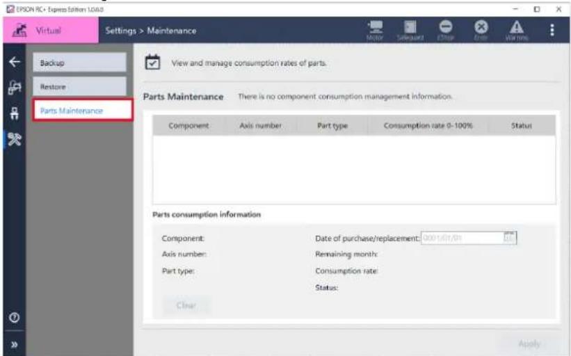
Operation procedure
1. Replace the part.
For how to exchange the components, refer to the following:
Manipulator Maintenance Manual
2. Select the line of replaced parts.
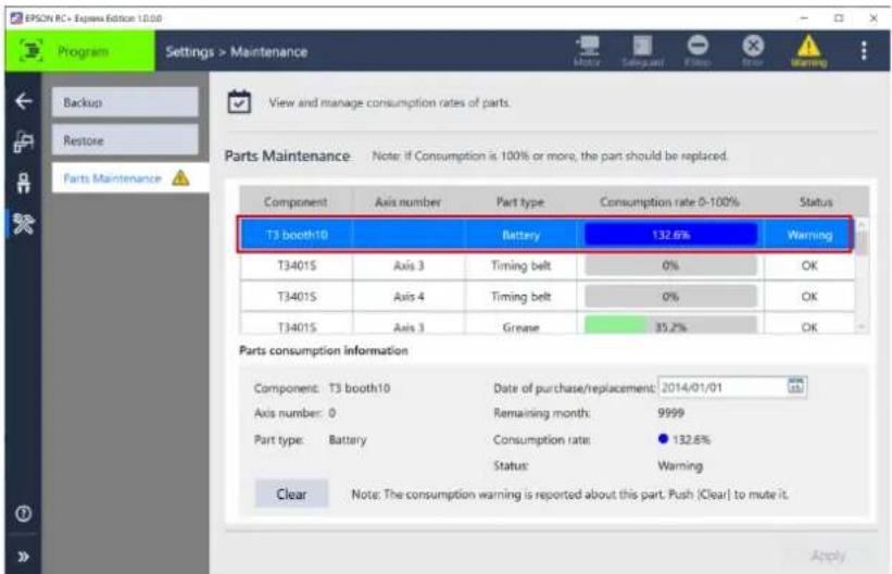
3. Change the date of [purchase/replacement].
![EPSW AC • Express Edition 1.08.0 Program Settings > Maintenance Backup Restore Parts Maintenance View and manage consumption rates of parts. Parts Maintenance Note: If Consumption is 100% or more, the part should be replaced. Component Axis number Part type Consumption rate 0-100% Status T3 booth10 Battery 132.6% Warning T3401S Axis 3 Timing belt 0% OK T3401S Axis 4 Timing belt 0% OK T3401S Axis 3 Grease 35.2% OK Parts consumption information Component: T3 booth10 Date of purchase/replacement: 2021/02/21 Axis number: 0 Remaining month: 9999 Part type: Battery Consumption rate: 132.6% Status Warning Clear Note: The consumption warning is reported about this part. Push [Clear] to mute it. Apply](/content/2026/05/821542/images/116433f19572dee80d6866b8b61d363a19e0bc099b595bf1e437803b2d731dd5.jpg)
![EPSON RC+ Express - Change the date of [purchase/replacement]. - 2](/content/2026/05/821542/images/27d6f04e566eb335e28142889ac1f450381462bb886a12d56f9b0c0f3b5d7456.jpg)
After changed [purchase/replacement], settings changed badge (*) is appeared in the [Parts Maintenance] tab on the left side of the screen.
4. When following appeared, tap button.
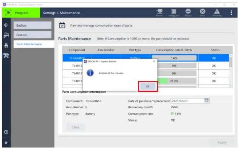
Warning and how to reset
The parts managed in Parts Maintenance, when the [Consumption rate] is “100%”, a warning displayed at controller status.
When displayed warnings, reset them immediately.
To display Parts Maintenance tab, tap Setting - [Maintenance] - [Parts Maintenance].
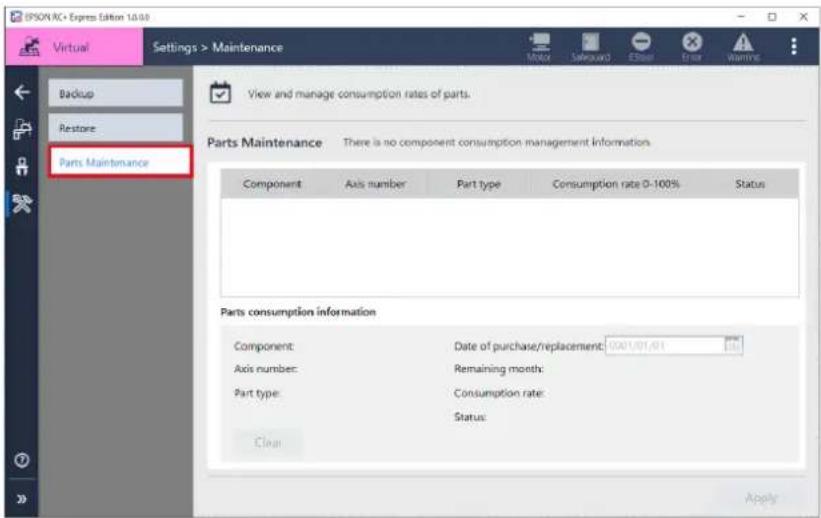
Operation procedure
- Select the waring state parts at [Parts Maintenance] tab – Parts Maintenance.
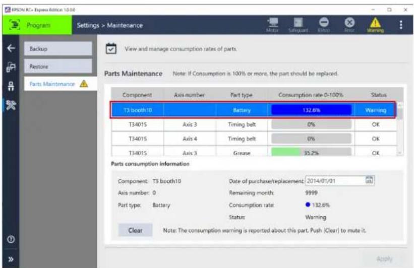
2. When following appeared, tap button.
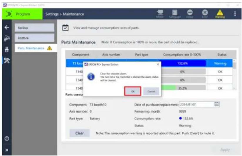
In this point, [Status], [Consumption rate] and [Remaining month] are not going to be restored. Change the settings of Parts consumption information. Making changes in Parts Consumption Information
Rebooting Controller
Reboot the controller. Available to change settings to Dryrun or Virtual I/O mode to reboot the controller. To display rebooting tab, tap [Settings].
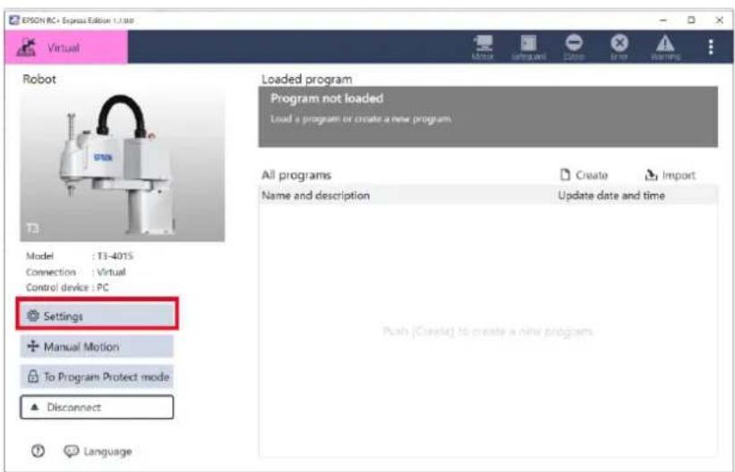
Operation procedure
1. Tap [Reboot Controller].
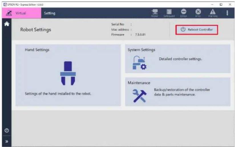
2. After following appeared, set details in case you needed.
Available to tap [Details] to select the controller status of when its rebooted.
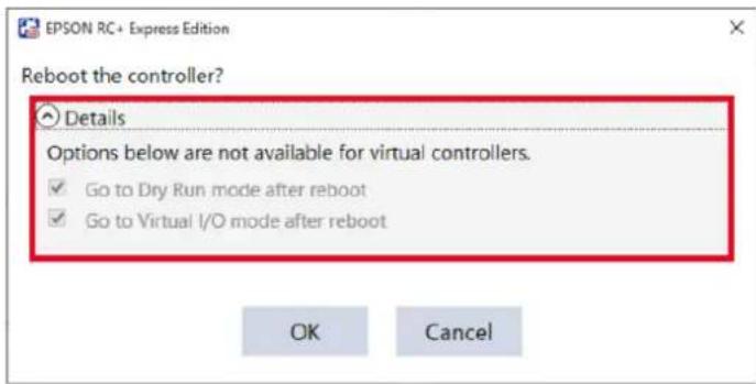
Following shows controller status:
| Item | Contents |
| Dryrun(Executed without connecting robot) | Without connecting controller to robot, all programs can be executed.Executes operation commands at almost the same time as when connected to a robot. |
| Virtual I/O mode | Executes program with Virtual I/O. There is no effect to the hardware I/O. |
3. Tap button.
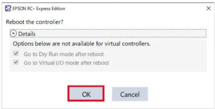
4. When following appeared, tap button.
This software cannot be used during the rebooting because the connection will be lost. After complete rebooting automatically reconnected to this software and available to use it.
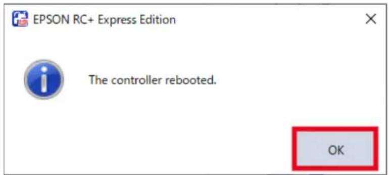
Appendix
Version
In this section, how to see version of the software is described.
Operation procedure
1. Tap - [About].
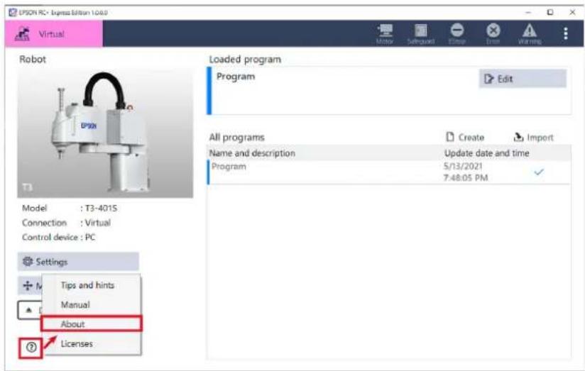
2. Check your version of the software.
Version: The version of the software.
Command set: The version of the commands which is used in programming.
Robot Package: The version of program for adding robot models.
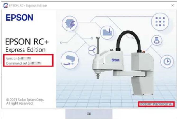
SOFTWARE LICENSE AGREEMENT
IMPORTANT! READ THIS SOFTWARE LICENSE AGREEMENT CAREFULLY BEFORE INSTALLING OR USING THIS SOFTWARE.
This software products and/or any accompanying explanatory written materials (the “Software”) should only be installed or used by the Licensee (“you”) on the condition you agree with SEIKO EPSON CORPORATION (including its affiliates and licensors, “EPSON”) to the terms and conditions of this Agreement. By installing or using the Software, you are representing to agree with all the terms and conditions of this Agreement. If you do not agree with the terms and conditions of this Agreement, you are not permitted to install or use the Software. In this Agreement, affiliates mean any corporation or entity of which EPSON owns, directly or indirectly, a majority of the assets or voting stock.
1. License.
EPSON grants you a personal, nonexclusive, limited license to
(i) install and use the Software on any single computer or EPSON's robot controller products, following the instructions, terms and conditions under the "Epson RC+Express Manual" and its "Setup";
(ii) make one copy of the Software for backup and archival purposes. For clarity, such backup and archival copy so made shall be treated as the Software herein;
2. Limitations.
You shall use the Software in a manner permitted herein. You agree not to (i) modify, adapt, translate or make any derivative works from the Software and (ii) attempt to reverse engineer, decompile, disassemble or otherwise attempt to discover the source code of the Software. Unless otherwise provided herein, you shall not share, rent, lease, encumber, sublicense, lend or distribute the Software.
3. Third Party Software
The Software may contain third party's software (“Third Party Software”, including open-source software, such as GNU General Public License and GNU Lesser/ Library GPL). If the Software contains the Third Party Software, you shall review and comply with the terms and conditions applicable to such Third Party Software before using the Software.
4. Ownership.
Excluding the Third Party Software, any title, ownership, intellectual property rights and any other rights in and to the Software shall remain with EPSON. You shall not be granted any title, ownership, intellectual property rights or any other rights in and to the Software unless explicitly provided herein. The Software is protected by Japanese Copyright Law and international copyright treaties, as well as other intellectual property laws and treaties. You agree not to remove or alter any copyright and other proprietary notices on any copies of the Software.
5. Protection and Security.
You agree to use your best efforts and take all reasonable steps to safeguard the Software to ensure that no unauthorized person has access to it and that no unauthorized copy, publication, disclosure or distribution of the Software is made. You acknowledge that the Software contains valuable, confidential information and trade secrets and that unauthorized use and copy are harmful to EPSON. You shall hold in strict confidence the Software and any information obtained in connection with the Software.
6. No Warranty.
You acknowledge and agree that the use of the Software is at your sole risk. THE SOFTWARE IS PROVIDED "AS IS" AND WITHOUT ANY WARRANTY OF ANY KIND. EPSON DOES NOT AND CANNOT WARRANT THE PERFORMANCE OR RESULTS YOU MAY OBTAIN BY USING THE SOFTWARE. EPSON MAKES NO WARRANTIES OF ANY KIND, EXPRESS OR IMPLIED, INCLUDING, BUT NOT LIMITED TO THE IMPLIED WARRANTIES OF NON-INFRINGEMENT, MERCHANTABILITY OR FITNESS FOR ANY PARTICULAR PURPOSE.
7. Limitation of Liability.
IN NO EVENT WILL EPSON BE LIABLE TO YOU, WHETHER ARISING UNDER CONTRACT, TORT (INCLUDING NEGLIGENCE), STRICT LIABILITY, BREACH OR WARRANTY, MISREPRESENTATION OR OTHERWISE, FOR ANY DIRECT, INDIRECT, CONSEQUENTIAL, INCIDENTAL OR SPECIAL DAMAGES, INCLUDING ANY LOST PROFITS OR LOST SAVINGS, EVEN IF EPSON OR ITS REPRESENTATIVE HAS BEEN ADVISED OF THE POSSIBILITY OF SUCH DAMAGES, OR FOR ANY CLAIM BY ANY THIRD PARTY. IN THE EVENT LIMITATION OF LIABILITY HEREUNDER IS FOUND INVALID OR UNENFORCEABLE BY A COURT OF COMPETENT JURISDICTION, THE AGGREGATE LIABILITY OF EPSON TO YOU FOR ANY DAMAGES OR LOSS SHALL NOT EXCEED THE TOTAL AMOUNT PAID BY YOU TO EPSON IN CONSIDERATION OF THE SOFTWARE.
8. Termination.
Without prejudice to any other rights EPSON has, this Agreement shall immediately terminate without any notice upon failure by you to comply with its terms. You may also terminate this Agreement at any time by uninstalling and destroying the Software. For clarity, you shall not be released from any obligations imposed prior to the termination of this Agreement.
9. Export Restriction.
You agree not to transfer, export or re-export the Software and any data or information which you obtained from the Software or in connection with this Agreement without a proper license under Japanese law, restrictions and regulations or the laws of the jurisdiction in which you obtained the Software.
10. Governing Law and Severability
This Agreement shall be governed by and construed under the laws of Japan without regard to its conflicts of law rules. If any provision herein is found invalid or unenforceable by a court of competent jurisdiction, it will not affect the validity of the balance of this Agreement, which shall remain valid and enforceable according to its terms.
11. Updating Software Version.
Epson may provide you an updated version of the Software for the purpose of improvement and bug-fixes. Such updated Software shall be deemed to be the Software and be governed by this Agreement.
12. Entire Agreement.
This Agreement is the entire agreement between the parties with respect to the Software and supersedes any communication, advertisement, or representation concerning the Software. This Agreement shall be binding upon and inure to the benefit of the parties hereto and their respective successors, assigns and legal representatives.
13. General Provisions.
(1) EPSON may change, modify or otherwise alter this Agreement in its sole discretion at any time with or without notice to you. You shall review this Agreement on a regular basis to acknowledge such changes. By using the
Software after any such changes have been made, you are deemed to agree to comply with, and to be bound by, the modified Agreement.
(2) Any translation of this Agreement is provided solely for your convenience and is not intended to modify the terms and conditions of this Agreement. In the event of a conflict between the Japanese version and any versions in other languages of this Agreement, the Japanese version shall prevail and govern.
14. U.S. Government End Users.
If you are acquiring the Software on behalf of any unit or agency of the United States Government, the following provisions apply. The Government agrees: (i) if the Software is supplied to the Department of Defense (DoD), the Software is classified as “Commercial Computer Software” and the Government is acquiring only “restricted rights” in the Software and its documentation as that term is defined in Clause 252.227-7013(c)(1) of the DFARS; and (ii) if the Software is supplied to any unit or agency of the United States Government other than DoD, the Government’s rights in the Software and its documentation will be as defined in Clause 52.227-19(c)(2) of the FAR or, in the case of NASA, in Clause 18-52.227-86(d) of the NASA supplement to the FAR.
©Seiko Epson Corporation 2021.
Uninstalling
How to uninstall this software.
Operation procedure
- Tap Windows Start menu - [Settings].
- Tap[Apps] - [Apps & features].
- Tap [EPSON RC + Express Edition], and tap [Uninstall].
List of SPEL+ Command Availability in RC+ Project Link
Use RC+ Project Link to import an EPSON RC+ SPEL+ project into this software for use. Overview of the feature of RC+ Project Link
Check the table below for the availability of the SPEL+ command.
This section describes unsupported commands.
Refer to "Summary of SPEL+ Commands" in the "SPEL+ Language Reference" manual for specific command names.
| Item Unsupported command | |
| System Management Commands | Shutdown, SysConfig |
| Robot Control Commands | AutoOrientationFlag, Brake, JumpTLS, SyncRobots, Where |
| Torque Commands | |
| Input / Output Commands | Input, RunDialog, Line Input, Line Input # |
| Point Management Commands | WorkQue List, ImportPoints, ExportPoints |
| Coordinate Change Commands | VxCalDelete, VxCalib, VxCalLoad, VxCalSave |
| Program Control Commands | |
| Program Execution Commands | |
| Pseudo Statements | |
| File Management Commands | |
| Fieldbus Commands | |
| Numeric Value Commands | |
| String Commands | |
| Logical Operators | |
| Variable Commands | |
| Security Commands | LogIn |
| Conveyor Tracking Commands | Cnv QueList |
| Force Sensing Commands | FSave, FExport, FImport |
| DB Commands | |
| PG Commands | Not supported |
| Collision Detection Commands | |
| Parts Consumption Commands | |
| Simulator Commands | Not supported |
| Hand Commands | |
| Vision Guide Commands *1 | VCal, VCalPoints, VCreateCalibration, VCreateSequence, VdefArm, VDefGetMotionRange, VDefLocal, VDefSetMotionRange, VDefTool, VDefToolXYZ, VDefToolXYZUVW, VDeleteCalibration, VEditWindow, VGoCenter, VLoad, VSave, VShowModel, VStatsSave, VStatsShow, VTeach, VTrain |
| Part Feeding Commands *2 |
*1 Reference: Vision Guide 7.0 Properties and Results Reference
*2 Reference: Part Feeding 7.0 Introduction & Software

- EPSON RC+ Express Manual
- FOREWORD
- TRADEMARKS
- TRADEMARK NOTATION IN THIS MANUAL
- NOTICE
- MANUFACTURER
- SEIKO EPSON CORPORATION
- CONTACT INFORMATION
- MANUALS
- Symbols
- How to Read a Manual
- Regarding screens and illustrations
- How to display tips and hints
- How to display a Manual
- - Searching by keyword
- - Jumping to the corresponding page from a bookmark
- - Printing
- - How to move a manual
- How to Read RC+ Manual
- Basics 1
- Setup 5
- Operating Robot 27
- Programming 41
- Functions of Command 65
- Various Program Examples (Tutorial) 95
- Pallet 133
- Point File Viewer 137
- Remote Control 141
- More Functions 153
- RC+ Project Link 161
- Trouble Shooting 171
- Settings 177
- Appendix 203
- Basics
- What's EPSON RC+ Express Edition?
- System Configuration
- Supported Robots
- Operating Environments
- How to Operate a Tablet
- Setup
- Advanced Preparations
- - Tablet (recommended), or PC
- - DVD drive
- - Cables
- Installing the Software
- Installing (From DVD Drive)
- Installing (From USB, Shared Folder)
- Operation procedure
- Enabling the RC+ Express Advanced
- Connecting to Robot
- Connecting to Robot (USB)
- Connect the Controller and the tablet using USB cable.
- Double-tap
- Choose the USB connection, and tap button.
- Connecting to Robot (Ethernet)
- Tap the <+> button.
- When following appeared, fill the blanks and tap the button.
- Connecting to Virtual Robot
- Home screen
- Status Bar
- Operating mode
- Program name
- Program descriptions
- Controller status
- Menu
- - System History
- - 3D View preference
- - 6-axis robot environment setting
- Closing the Software
- Operating Robot
- Main Monitor
- Manual Motion
- Motor
- 3D View
- Coordinate values
- Joint value
- Jog Mode (Easy, Joint, World, Tool)
- ·Easy
- - Joint
- - World
- • Tool
- Jog Speed & Jog Distance
- Jog Speed
- Jog Distance
- - Move with a certain width
- - Move continuously
- - Specify custom movement distance
- Arm Posture
- Singularity
- Turn the motor "ON".
- Select Jog Mode (Easy, Joint, World, Tool).
- Tap the icon on the Jog panel or hold it down or drag
- Programming
- Program Screen Layout
- Program Screen
- Setting a Program Operation
- Select a path type from [Move to] or [Move linearly to].
- Move the knobs to change the default values of "Speed" and "Accel".
- Set the waypoint.
- Set [LJM].
- Creating/Editing/Managing a Program
- Creating a Program
- Creating a Program Using a Template
- Tap [Create].
- Select a template from the list.
- Enter "Program Name" and "Description", and then tap button.
- Beginning with an Empty Program
- When following screen is displayed, select [Empty Program].
- Enter "Program Name" and "Description", and then tap the button.
- Executing a Program
- Executing a Program to Check for Problems
- Tap the |Rehearsal|.
- When a confirmation dialog appears, confirm the safety of your surroundings, and then, tap the button.
- Press and hold the button.
- Checking Event Log
- Rollback
- Before executing rollback, clear all the error state including EStop,
- Press and hold the button to reverse the motion.
- Editing a program
- Command Operation List
- Adding a Command
- Copy and Paste
- Select a command to be copied and tap
- Select the command which is at the position to insert and tap (Paste).
- Cut and Paste
- Select a command to be cut and tap do(Cut) .
- Select the command which is at the position to add and tap (Paste).
- Managing a Program
- Switching Loaded Program
- Select a program and tap - [Rename].
- Change the name and description of the program and tap button.
- Duplicating
- Deleting
- Functions of Command
- About Command
- Badge
- Comment
- Command help
- Command Function List:
- Motor ON
- ■ Detailed Settings
- Power
- Motor OFF
- Move To
- ■Detailed Settings
- Destination
- Point
- Setting procedure
- Set the axis, posture flag, and LJM.
- Speed
- Move linearly to
- file
- Grip
- General
- Release
- Container
- Pick from
- ■ Details of series of operations
- ■ Settings of properties
- Waypoint/Evacuation point
- Decompose commands
- Place at
- Move Forward
- Select a pallet
- Reset
- Output
- Output Target
- Signal
- Wait
- Detailed Settings
- Wait Target
- Steps to set conditions
- Tap [+ Add Condition].
- Tap the pull down and select the condition type.
- - Setting with (Input signal bits)
- - Setting with (Hand)
- - Setting with
- (RC+)
- Tap <+> button to add more conditions.
- Timeout
- Loop
- Loop Count
- Loop Condition
- Add Exit If
- Exit If
- If
- Tap [+Add Condition].
- Tap the pull down list and select the condition type.
- - Setting with ⋯ (Input signal bits)
- - Setting with \_\_\_\_ (Pallet)
- - Setting with (Timeout)
- When multiple conditions are needed, tap <+> button to add conditions.
- Quit
- Ask
- Notify
- Event Log
- SPEL+ Command
- Variable
- RC+ Project Link
- Various Program Examples (Tutorial)
- Pick and Place (between 2 points)
- Tap |Create|.
- Tap [Edit].
- When the following screen appears, tap the "Motor On" command to add.
- Follow the instructions below to configure the motion to move to a picking point and then grip a workpiece.
- Follow the instructions below to configure the motion to move to the point where the workpiece is to be placed and then release the workpiece.
- Follow the instructions below to configure the motion to repeat "Pick from" and "Place at".
- Tap [Start] to check for problems of the robot motion.
- Tap the "Motor On" command in the program to set the [Power] to "High".
- Tap the button, and execute the program following the screen instructions.
- Pick and Place (between 3 points)
- Follow the instructions below to configure the motion to move to a processing point and then release a workpiece.
- Follow the instructions below to configure the motion to move to a fixed point.
- Follow the instructions below to configure the waiting time until the processing is completed.
- Follow the instructions below to configure the motion to move to the processing point.
- Tap the button to check for problems of the robot motion.
- Palletizing
- Confirm that [Empty Program] is selected.
- When the editing screen appears, tap
- to go to Pallets screen.
- Tap the button.
- Set the number of cells using the <+> and <-> button, then tap the button.
- Turn the motor "On" to teach the pallet position.
- Select the |Begin| point of the palletizing and [Direction] from the begin point and tap button.
- Go back to the program screen and follow the instructions below to add the "Motor On" and "Loop" commands.
- Follow the instructions below to add the "Pick from" command above the "Wait" command and tap button.
- Move the robot to the picking point and tap the button. Operating Robot
- Follow the instructions below to add the "Place at" command and configure.
- Follow the instructions below to add the "Move forward" command and configure.
- Tap [Start] to execute the program.
- Sorting Non-defective/Defective Products
- Select - [Duplicate] on the program of pick and place (between 3 points).
- Tap the button.
- Enter the following and tap the button.
- Follow the instructions below to add a command that instruct the inspection machine to start inspection from the program.
- Follow the instructions below to add the second "Output" command and configure.
- Follow the instructions make the program wait for the result from the inspection machine.
- Follow the instructions below to make the program branch depending on the inspection result.
- Follow the instructions below to make the program handle non-defective products.
- Follow the instructions below to configure the "Then" command.
- Follow the instructions below to configure the "Else" command.
- Follow the instructions below to add the "Event Log" command and configure.
- Tap [Start] to check for problems of the robot motion.
- Fixed Cycle Signal Output (RC+ Project Link)
- When the following screen is displayed, select [Fixed Cycle Signal Output].
- Enter "Program Name" and "Description" then tap the button.
- Tap [I/O].
- Enter the following and tap the button.
- Follow the instructions below to configure the "Start Flashing" command.
- Create motion of the robot.
- Tap [Start] to check for problems of the robot motion.
- Cycle Time Measurement (RC+ Project Link)
- Create motion of the robot.
- Tap [Start] to check the robot motion.
- Check the measured cycle time.
- Pallet
- Pallet Configuration
- Creating a New Pallet
- Tap the button.
- Point File Viewer
- Point File Viewer Screen
- Defining a Point
- 3D View (Point File)
- List View
- Details View
- Operation Buttons
- Remote Control
- Remote I/O in This Software
- Using Remote I/O
- Tap Home - [Settings] to display setting.
- Choose "Remote I/O" at [System Settings] - [Controller Configuration] - [Controller device change].
- Choose Input bit of "Start" and "SelProg1" at [Remote Control] - [Remote Input/Output], and tap the button.
- Follow the procedure below.
- Open the Program edit screen, and tap [Remote I/O].
- When following appeared, adjust the speed limitation and tap the button.
- Tap [I/O].
- Set the Input bit of "Selprog1" to "ON" then set the Input bit of "Start" to "ON".
- Using Remote Ethernet
- Choose "Remote Ethernet" at [System Settings] - [Controller Configuration] - [Controller device change].
- Fill each item at the [Remote Control] - [Remote Ethernet], and tap .
- Specify "1" to the parameter (function number) from external device such as PLC, and execute the "Start" command.
- Setting I/O Functions
- I/O Functions
- Checking for the I/O Setting
- Setting for the I/O
- More Functions
- Registering Custom Template
- Editing custom template
- Deleting custom template
- Exporting and Importing a Program
- Exporting
- Select the program to export and tap - [Export].
- Tap the button and specify the saving destination of the program you want to export and tap the button.
- Importing
- Tap the button and specify the saving destination of the program you want to import and tap the button.
- Exporting Program to RC+
- SPEL+ Code Viewer
- Copy to clipboard
- Export point file
- Program Protect Mode
- What you can do
- What you cannot do
- Overview of the feature of RC+ Project Link
- Conditions to Use RC+ Project Link
- Preparations to use the feature of RC+ Project Link
- Restrictions when option is disabled
- Creating RC+ Project
- Interface Definition File RCEE Exports.prg
- Declare Variable
- Definition of function
- Samples of RCEE\_Exports.prg
- Restriction When Creating RC+ Project
- - File
- - Function name
- - Using point file
- - Using pallet
- - Using Tool
- - Using robot parameters on RC+
- ·SPEL+ Command
- - Be careful for using command that interact with RC+ EE program
- - Unsupported functions
- Setup for RC+ and Building the Project
- Preparing destination when build a program
- - Connecting robot by using USB on RC+ EE
- - Connecting robot by using Ethernet on RC+ EE
- - Connecting to virtual robot on RC+EE
- Preparing RC+ Project
- Importing RC+ Project on RC+ EE
- Setup procedure
- Tap [RC+ Project Link] button.
- Tap [specify project...] button.
- Check in the check box of function to import as a command.
- Tap [OK] button.
- Creating a Program Using Imported Commands
- Executing a Program Using RC+ Project Link
- Tap [Start] button to start the program.
- Tap [Run] at dialog to check for run.
- Trouble Shooting
- The icon at the top of the screen lights up
- Powered off accidentally while editing program
- Connecting to robot failed
- Solution:
- I want operation speed of the robot to move faster
- [Arm reached the limit of motion range.] message showed up
- Troubles when using RC+ Project Link
- An error occurs when importing a program
- An error occurs when starting the RC+ project
- An error occurs when a program is running
- Robot is in singular postures
- Returning from singular postures
- Avoiding singular postures by setting environments
- The robot stops even if the posture to avoid singular postures is set
- Failed in Rollback
- Settings
- Robot Settings
- System Settings
- Controller Configuration
- Controller device setting
- Network address change
- Environment Settings
- Inputs / Outputs
- Fieldbus Slave
- Remote Input/Output
- Remote Ethernet
- Motion Range
- XYZLimits Setting
- Range Setting
- Options
- Hand Settings
- Select a hand from pull down [Hand Type :].
- Set the I/O when gripping / releasing a work, and tap button.
- Tap Grip / Release and test the operation.
- Tool Offset
- Tap [Tool Offset Wizard].
- Weight
- Distance, Moment of Inertia, and Eccentricity
- Language Settings
- Maintenance
- Backup
- Restore
- Tap .
- Parts Maintenance
- Parts consumption information
- Consumption rate
- Replace the part.
- Select the line of replaced parts.
- Change the date of [purchase/replacement].
- When following appeared, tap button.
- When following appeared, tap button.
- Rebooting Controller
- Tap [Reboot Controller].
- After following appeared, set details in case you needed.
- Tap button.
- Appendix
- Version
- Tap - [About].
- Check your version of the software.
- SOFTWARE LICENSE AGREEMENT
- IMPORTANT! READ THIS SOFTWARE LICENSE AGREEMENT CAREFULLY BEFORE INSTALLING OR USING THIS SOFTWARE.
- License.
- Limitations.
- Third Party Software
- Ownership.
- Protection and Security.
- No Warranty.
- Limitation of Liability.
- Termination.
- Export Restriction.
- Governing Law and Severability
- Updating Software Version.
- Entire Agreement.
- General Provisions.
- U.S. Government End Users.
- Uninstalling
- List of SPEL+ Command Availability in RC+ Project Link
Brand : EPSON
Model : RC+ Express
Category : Uncategorized