
KWE-403ID6 - Uncategorized ALPINE - Free user manual and instructions
Find the device manual for free KWE-403ID6 ALPINE in PDF.

| Product Type | Steering wheel remote control interface installation kit |
| Brand | Alpine |
| Model | KWE-403ID6 |
| Category | Vehicle interface / wiring harness |
| Compatible Vehicles | IVECO Daily VI open dash with steering wheel remote control (SWRC) |
| Vehicle Years | 2014 - 2019 |
| Kit Contents | SWRC interface wiring harness with multiple connectors and cables |
| Interface Type | Wiring harness interface for radio integration |
| Required Kits | X903D-ID, KIT-7ID, KIT-F9ID |
| Power Supply | 12V DC from vehicle |
| Speed Signal | Yellow wire (must be connected to vehicle speed pulse) |
| Reverse Signal | White wire (must be connected to vehicle reverse light) |
| SWRC Signal | Three voltage cables (Pink, Pink/Black, Brown) for steering wheel remote control |
| LIN BUS Connection | White and Brown wires to key harness or LIN cable in X903D-ID / KIT-7ID / KIT-F9ID |
| Camera Input | Yes (connector point 3 on harness) |
| AUX Input | Yes (connector point 6 on harness) |
| Antenna Output | Power antenna output (point 10) |
| Remote Output | Camera control / remote output (point 9) |
| Installation | Must be performed by a qualified professional installer |
| Document Language | English |
| Document Pages | 4 |
Frequently Asked Questions - KWE-403ID6 ALPINE
User questions about KWE-403ID6 ALPINE
0 question about this device. Answer the ones you know or ask your own.
Ask a new question about this device
Download the instructions for your Uncategorized in PDF format for free! Find your manual KWE-403ID6 - ALPINE and take your electronic device back in hand. On this page are published all the documents necessary for the use of your device. KWE-403ID6 by ALPINE.
USER MANUAL KWE-403ID6 ALPINE
Steering wheel remote control interface installation kit for IVECO
Model: Daily VI open dash with SWRC
Year: 2014 > 2019
Kit content: SWRC interface wiring harness
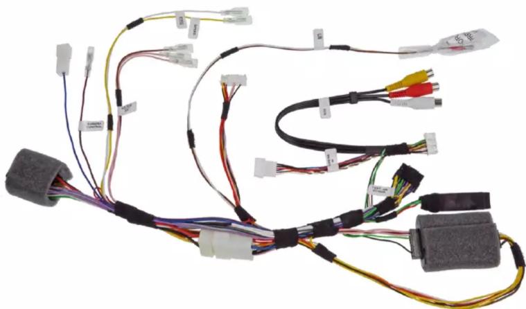
natural_image
Electrical wiring harness with multiple connectors and cables (no visible text or symbols)All installation work must be performed by a qualified professional installer only. The manufacturer / dealer is not liable for any kind of incidental or indirect damages. 06/2020 ALL RIGHTS RESERVED. Technical changes possible. No liability for misprints.
INSTALL THIS HARNESS INSTEAD OF THE POWER CABLE CONTAINED IN THE X903D-ID, KIT-7ID AND KIT-F9ID KITS FOLLOWING THE PROCEDURES BELOW:
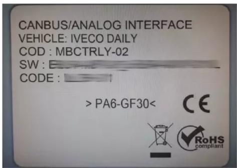
REMOVE THE INTERFACE WITH THE LABEL SHOWN BELOW FROM THE KITS: X903D-ID, KIT-7ID AND KIT-F9ID:
AND CONNECT IT TO POINT (4) SEE THE NEXT PAGE.
Content and wiring harness connections
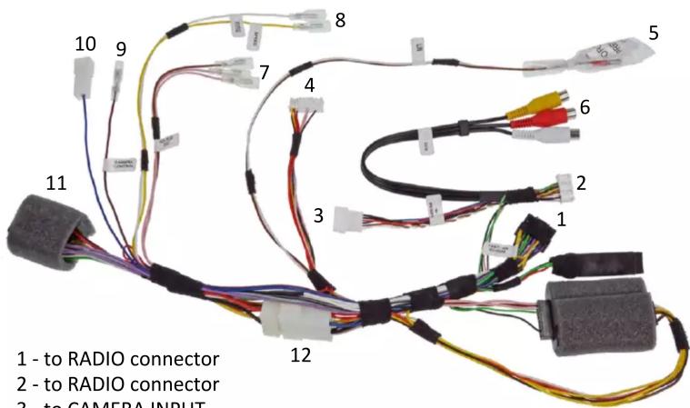
1 - to RADIO connector
2 - to RADIO connector
3 - to CAMERA INPUT
4 - to X903D-ID / KIT-7ID / KIT-F9ID interface
5 - to LIN BUS connector cable:
to key harness contained in X903D-ID,
to LIN cable contained in KIT-7ID & KIT-F9ID
6 - AUX input
7 - connect these 3 cables to the 3 voltage SWRC cable in the vehicle:
Pink with Pink cable
Pink/Black with Pink/Black cable
Brown with Brown cable
8 - to SERVICES provided by the vehicle:
Yellow - to vehicle SPEED pulse (MUST be connected to vehicle)
White - to vehicle REVERSE signal (MUST be connected to vehicle)
9 - CAMERA control / REMOTE output
10 - POWER ANTENNA output
11 - to CAR connector
12 - external power access
- Cable Connections 2.1 Connecting Reverse Signal (White cable (point 8 / page3))
Connect the harness as indicated in the installation manual (IM_X903D-ID_EN) of X903D-ID (page 26-27) to vehicle and as indicated on the last page (8). Please also note the points on the following pages of these instructions.
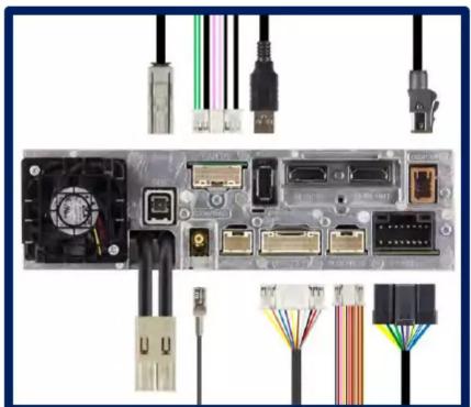
natural_image
Internal components of a computer interface with connectors and ports (no visible text or labels)- Speed and Reverse Cable Connections (point 8 / page 3)
Connect the two SERVICES cables.
→ Yellow - to vehicle SPEED pulse (MUST be connected to vehicle)
→ White - to vehicle REVERSE signal (MUST be connected to vehicle)
natural_image
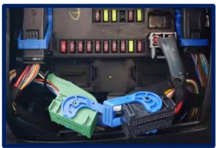
Interior view of a car's internal battery pack with colored connectors and wiring (no visible text or symbols)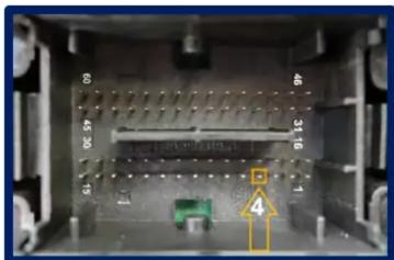
natural_image
Interior view of an electronic device casing with labeled components (no readable text or symbols)Body Computer/Fuse Box
Left Connector F (Green or Black):
Pin 4 = Reverse Light
Remove the cover of the Green or Black plug. The Grey/Green or White/Green cable carries the reverse signal. Remove the terminal from the connector housing. Connect the White cable (point 8 / page 3) from the wiring harness to the Grey/Green or White/Green cable from the vehicle connector.
2.2 Connecting Speed Signal (Yellow cable (point 8 / page3))
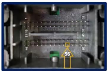
Body Computer/Fuse Box
Right Connector D (Black):
Pin 56 = Speed Signal
Remove the cover of the Black plug.
The Orange cable, if proven otherwise, installing a PIN, carries the speed signal. Remove the terminal from the connector housing.
Connect the White cable (point 8 / page 3) from the wiring harness to the Grey/Green or White/Green cable from the vehicle connector.
natural_image
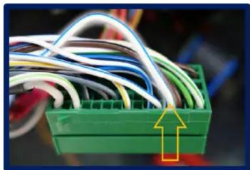
Close-up of a green plastic connector with multiple wires and a yellow arrow pointing to it (no text or symbols visible)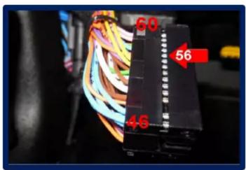
3. Three Voltage SWRC Cable Connections
There are a few vehicles that control the steering wheel remote control via three voltages cables. The original delivery status of the X903D-ID does not work for these vehicles, because the original connection wiring harness does not have a connection for these 3 voltage cables. By connecting these 3 cables, a transmission to the functionality of the steering wheel remote control is done.
natural_image
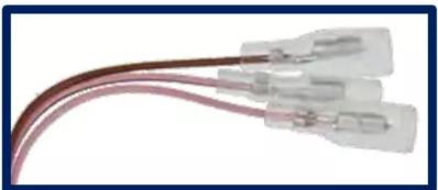
Close-up of a red and pink cable with two transparent connectors (no text or symbols visible)Connect the three voltage cables (point 7 / page 3) for SWRC.
→ Pink with Pink cable in vehicle
→ Pink/Black with Pink/Black cable in vehicle
→ Brown with Brown cable in vehicle
You can find these 3 cables in the radio slot, close to the original radio connection wiring harness.
natural_image
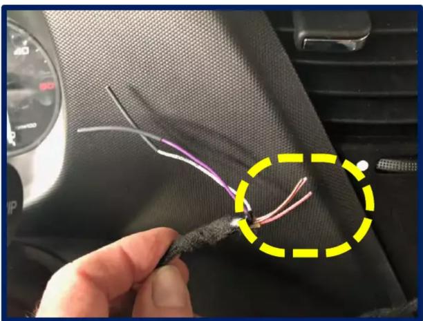
Close-up of a car interior showing wires and a black fabric patch, with a yellow dashed circle highlighting a section (no text or symbols visible)4. LIN BUS Cable Connection (White and Brown cable (point 5 / page3))
Connect the two LIN BUS connector cables:
→ to key harness contained in X903D-ID or
→ to LIN cable contained in KIT-7ID & KIT-F9ID
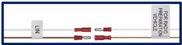
5. Interface Connection (point 4 / page3)
Connect the interface contained in X903D-ID, KIT-7ID or KIT-F9ID to the wiring harness (point 4 /page 3).
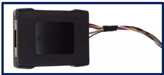
natural_image
Close-up of a black rectangular electronic device with multiple wires extending from its side (no visible text or symbols)
Brand : ALPINE
Model : KWE-403ID6
Category : Uncategorized