
PCM3-CAM NTV-KIT100 - Uncategorized NAV-TV - Free user manual and instructions
Find the device manual for free PCM3-CAM NTV-KIT100 NAV-TV in PDF.


User questions about PCM3-CAM NTV-KIT100 NAV-TV
0 question about this device. Answer the ones you know or ask your own.
Ask a new question about this device
Download the instructions for your Uncategorized in PDF format for free! Find your manual PCM3-CAM NTV-KIT100 - NAV-TV and take your electronic device back in hand. On this page are published all the documents necessary for the use of your device. PCM3-CAM NTV-KIT100 by NAV-TV.
USER MANUAL PCM3-CAM NTV-KIT100 NAV-TV
3950 NW 120th Ave, Coral Springs, FL 33432
Tel. 561-955-9770 Fax. 561-955-9760
www.nav-tv.com info@nav-tv.com
Front and rear camera interface
Enables a backup camera and a secondary on the factory 2009 and Up Porsche PCM 3.0 Radios
Certain features are intended for passenger and off-road use only. User must obey all State and Federal regulations
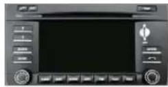
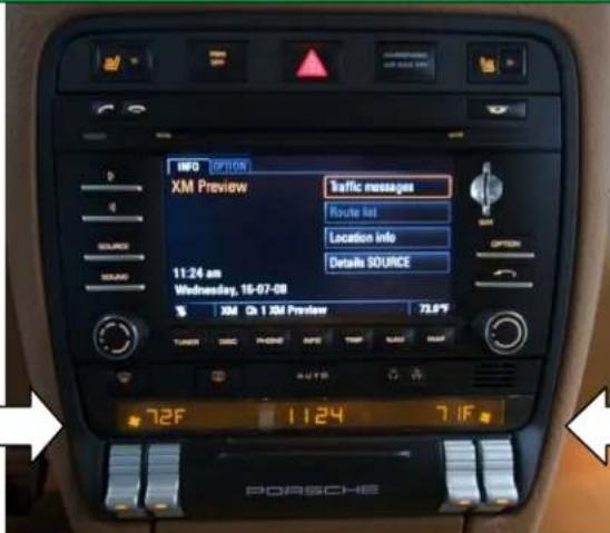
Make sure your radio looks like this prior to installation
Kit Contents
natural_image
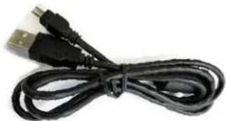
Coiled black cable with USB port (no text or symbols visible)USB Cable (Updates)
NTV-CAB009

text_image
NAV-TV® interfacing the future!PCM3-CAM Module
NTV-ASY107
natural_image
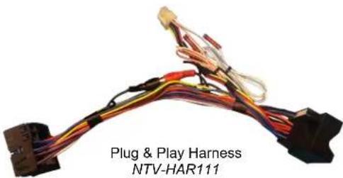
Coiled electronic circuit lines with connectors, labeled 'Plug & Play Harness NTV-HAR111' (no other text or symbols)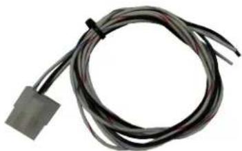
natural_image
Coiled electrical component with a small terminal block attached (no visible text or symbols)VSW-R Trigger
Harness
NTV-HAR066
VSW-R Board
NTV-ASY187
text_image
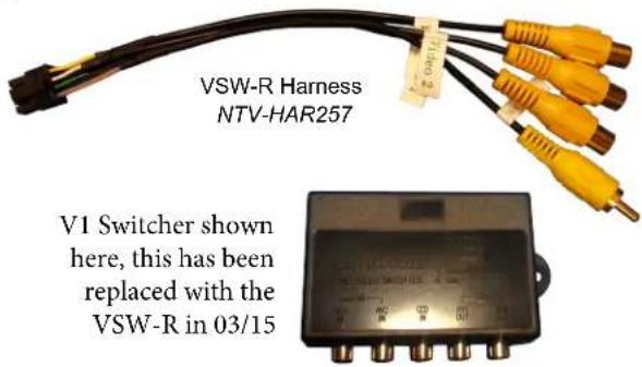
VSW-R Harness NTV-HAR257 V1 Switcher shown here, this has been replaced with the VSW-R in 03/15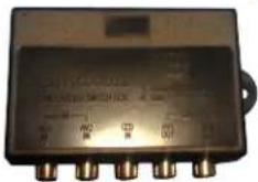
Filter Harness Description and Diagram
| Wire Functions | Wire Colors | Fig. 2 - Connection plug on Can Filter |
| 1. CAN Hi to Vehicle.2. CAN Lo to Vehicle3. Chassis Ground.4. +12V Output to Camera.5. CAN Hi to PCM.6. CAN Lo to PCM.7. +12V Battery8. +12V Output to switcher and front Flir IR camera. | 1. Yellow2. Blue3. Black4. White/Red5. Yellow6. Blue7. Red8. White/Blue | 8 pin Molex connector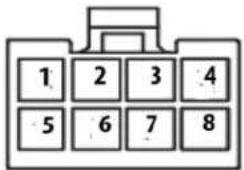 Wire side view Wire side view |
Installation Part 1
text_image
INFO (OPTION) XM Preview Traffic messages Route list Location info Details SOURCE 11:24 am Wednesday, 16-07-08 3 AM Ch 1 XM Preview 73.6°F TURER TIME AUTO AUTO AUTO 72F 11:24 71F PORSCHE- Insert a soft pry tool into the space between the lower black fascia piece and the lower side of the dash and gently pry the fascia towards the rear of the vehicle to release the mounting clips. Follow the fascia around either clockwise or counterclockwise to release the remainder of the mounting clips. Set aside the fascia.
natural_image
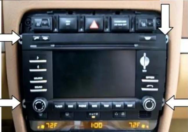
Interior view of a car dashboard with digital displays and control knobs (no readable text or symbols)- Remove (4) t20 torx screws from the sides of the radio and pull the radio gently out of the dash in order to disconnect all stock cables and antenna connectors.
text_image
STARS Laser Protection Safety: 100% U C B A B C D E F G H I J K L M N O P Q R S T U V W X Y Z A B C D E F G H I J K L M N O P Q R S T U V W X Y Z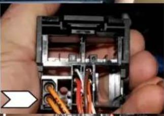
natural_image
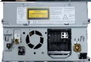
Close-up of hands holding an open electronic device with visible internal components and wiring (no text or symbols)- View of rear of radio and stock radio harness. Remove the fiber optic connector from the original harness by gently prying up on the locking tab with a pick tool.

natural_image
Two-panel photo showing hands installing or adjusting a car interior panel with wires and components (no visible text or symbols)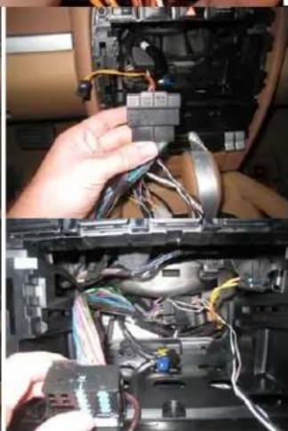
natural_image
Close-up of hands installing or connecting electronic components into a car chassis (no visible text or symbols)- With the fiber unplugged from the factory harness plug the aftermarket harness into the original harness and secure it by closing the stock locking tab. Attach the PCM3CAM module to the aftermarket harness and secure the filter to the back of the radio cavity with either double sided tape or Velcro. Fold the harness in the cavity as shown to allow clearance for the radio.
Installation Part 2
natural_image
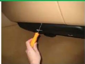
Close-up of a hand using a tool to trim a black car seat cover (no text or symbols visible)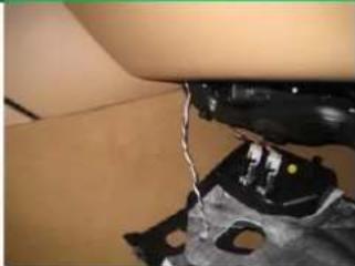
natural_image
Close-up of a person's arm with a medical device attached, showing no visible text or symbols- Drop the plastic panel over the passenger side kick panel area by taking out (1) t20 Torx screw and pulling the panel towards the floor. Run the black, white/blue and white/red wires from the new radio harness into the opening as in the picture to your left. These wires will power your reverse and front cameras, as well as the video switcher.
natural_image
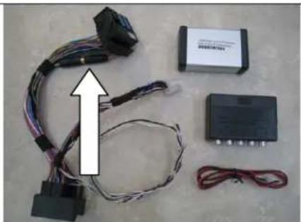
Electrical wiring and electronic components laid out on a surface, including a black connector, battery, and terminal block (no visible text or symbols)- If your vehicle is not equipped with a stock camera and you are not installing a front camera then simply unplug the male RCA end from the female in the aftermarket harness and run your camera's video RCA directly to the female plug. Connect ground for the reverse camera to the black wire and 12 volt positive to the white/red from step 5 and insulate the white/blue wire. Skip to step 8.
text_image
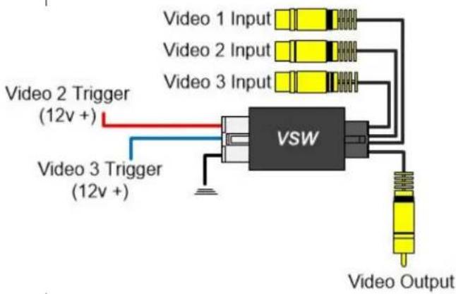
Video 1 Input Video 2 Input Video 3 Input Video 2 Trigger (12v +) Video 3 Trigger (12v +) VSW Video OutputVehicles with factory camera VSW-R installation
7a. Extend and plug the female RCA (radio side) of the harness into AV1 out. Extend and plug the male RCA (vehicle side) into AV1 in. Connect a front camera, for example, a Flir night vision camera RCA into Video 2 in. Connect the black ground wire from step 5 to both the ground of the front camera and the ground (black wire) from the video switcher. Connect the 12v wire (Video 2 Trig) of the switcher (white/red wire) to the white/blue wire from the module.
Vehicles without factory camera switcher installation
7b. Extend and plug the female RCA (radio side) of the harness into Video Output. Plug the RCA from your aftermarket rear view camera into Video 1 input (VSW-R). Connect a front camera, for example, a Flir night vision camera RCA into Video 2 in. Connect the black ground wire from the switcher to the ground from the switcher, the reverse camera and the front camera. Connect the white/red wire to the 12v wire to your aftermarket back up camera. Connect the white/blue wire to the 12v wire on your front vision camera
natural_image
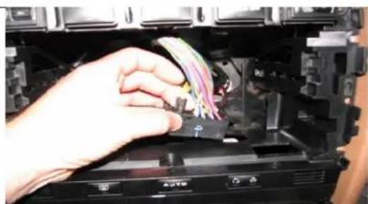
Close-up of a hand inserting colored cables into a device casing (no visible text or symbols)- Plug the fiber optic cable you unplugged in step 3 into the aftermarket harness. Reconnect all the antenna, power and all other connectors back into the radio and slide the radio back into the dash. Reassemble in the reverse order as steps 1,2 and 5. Now you are ready to proceed to the programming and operations section. Good job!
Programming
natural_image
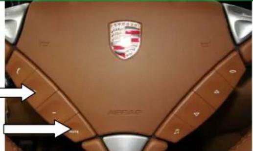
Top-down view of a car's steering wheel with BMW logo and brand name (no readable text or symbols beyond branding)- Press and hold down the + button on the steering wheel. While continually holding down the + button, press and hold down the mute button. Continue to hold down the mute button and release the + button.
natural_image
Interior view of a car dashboard with multiple monitors and control panels (no readable text or symbols)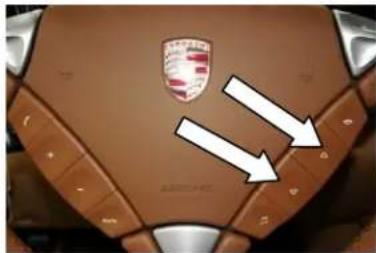
natural_image
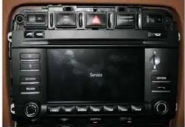
Top-down view of a car's backrest with a Mercedes-Benz logo and two white arrows pointing to specific areas (no text or symbols on the car itself)- The radio screen will now display the word SERVICE. While SERVICE is displayed on the screen press the up arrow within 7 seconds and Hold for 4 seconds to program the PCM for a reverse camera. If the PCM3CAM module is ever removed from the original vehicle you must first enter service mode and press the down arrow for 4 seconds to deprogram the original PCM BEFORE the filter is removed. If this is not done the filter will not work on any other vehicle.
text_image
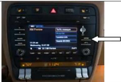
MT 24:00 XM Pssow Take remote Take off Take off 10:30 am Take off 10:07:00 Take off 30:00 325 1.124 7.5- After the radio reboots first select the option button on the right of the PCM. Then select "rear view camera" and then make sure the "automatic" feature is highlighted. Automatic means that every time the vehicle goes into reverse the PCM screen will show the backup camera image.
Operation
text_image
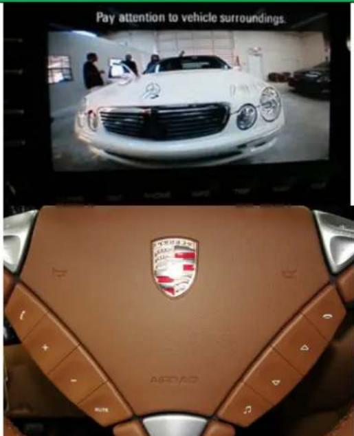
Pay attention to vehicle surroundings. ASAD- Place the vehicle in reverse and your image will appear on the screen. When putting the vehicle back in drive the image will stay on the screen for up to 20 seconds or until the vehicle reaches 7 mph.
- To enable the rear view camera while in motions simply double click the mute button within 1 second. To deactivate the camera while in motion double click the mute button again.
- It the s witcher is used to switch between two cameras, the double click the mute command will alternate between reverse camera, factory screen, front camera, factory screen.
- No matter what is showing on the screen the PCM will switch over to the reverse camera image any time the vehicle is placed into reverse.
- This module is only intended for front and rear view cameras. You will always have the "Pay Attention To Vehicles Surroundings" disclaimer at the top of the screen.
Note: Camera will not operate when the rear hatch is open.