AP-500AC - Access Point Silex - Free user manual and instructions
Find the device manual for free AP-500AC Silex in PDF.


User questions about AP-500AC Silex
0 question about this device. Answer the ones you know or ask your own.
Ask a new question about this device
Download the instructions for your Access Point in PDF format for free! Find your manual AP-500AC - Silex and take your electronic device back in hand. On this page are published all the documents necessary for the use of your device. AP-500AC by Silex.
USER MANUAL AP-500AC Silex
1-3. User Registration and Customer Services .... 5
User registration....5
Product Information....5
Customer Support Center 5
2. About AP-500AC ....7
2-1. Features 7
2-2. Parts and Functions....9
2-3. Hardware Specification....11
2-4. Software Specification....13
2-5. Power Supply....14
2-6. Wireless Interference Information....15
Notes....15
DFS....17
2-7. Notes on Security....18
2-8. OpenSSL License 19
3. Configuration Using Web Page......23
3-1. Displaying Web Page of AP-500AC (Initial Configuration) 23
Displaying Web Page Using Wired LAN 24
Displaying Web Page Using Configuration Mode ....29
Displaying Web Page Using Wireless LAN ....33
Displaying Web Page by Smart Wireless Setup ....39
Displaying Web Page Using External Registrar....46
3-2. Displaying Web Page of AP-500AC (After Initial Configuration)...... 51
3-3. Configuration at Web Page....53
3-4. Installing AP-500AC....58
Location of Installation....58
Change the Antenna Direction....60
Connect AP-500AC to a network 63
4. Connecting Wireless Device......65
4-1. Connecting PC....65
4-2. Connecting Wireless Device Using Smart Wireless Setup Switch....69
4-3. Connecting Wireless Device by Push Button Method of Web Page.....72
4-4. Connecting Wireless Device by Entering PIN Code on Web Page ... 76
5. Other Features 81
5-1. System Status of Connected Wireless Device 81
5-2. DHCP Server Feature....83
5-3. IEEE802.1X Authentication 86
Network Configuration....86
IEEE802.1X Authentication....86
IEEE802.1X Authentication Settings 87
5-4. WDS Feature....90
WDS Connection....91
WDS Configuration 93
What If WDS Connection Fails?......101
Checking WDS Connection Status from Web Page......107
5-5. VLAN Feature ....110
VLAN Configuration....111
5-6. Mac Address Filter....117
Filter Type ....117
MAC Address List....118
MAC Address Filter Setting 119
5-7. Device Server Feature....123
Downloading & Installing SX Virtual Link ......124
Sharing USB Devices over the Network....129
Uninstalling SX Virtual Link....132
5-8. Log Output ....134
Getting Started....135
Log Output Settings....136
Retrieving the Log Saved into USB Storage Device ....139
Notice When Using the Log Output ....144
5-9. Saving Log 145
Types of Log....145
Retrieving/Deleting System Log....148
Retrieving Event Log 152
5-10. Configuration Import/Export 154
Configuration Export....155
Configuration Import....157
5-11. Maintenance Feature....161
Restarting 161
Factory Default Configuration....164
Firmware Update 167
5-12. Product Search Utility 168
Downloading & Installing the Product Search Utility......168
Using Product Search Utility....173
Uninstalling the Product Search Utility ....175
A. Appendix ...... 177
A-1. List of All Settings ....177
A-2. Troubleshooting....210
1. Introduction
Thank you for purchasing the Access Point AP-500AC (called "AP-500AC" below).
1-1. Introduction
This manual provides information on how to configure and use AP-500AC. Please read the Safety Instructions carefully before you begin.
Disclaimers
- The unauthorized transfer or copying of the content of this manual, in whole or in part, without prior written consent is expressly prohibited by law.
- The content of this manual is subject to change without notice.
- This manual was prepared to accurately match the content of each OS, but the actual information shown on the computer monitor may differ from the content of this manual due to future OS version upgrades, modifications, and other changes.
- Although every effort was made to prepare this manual with the utmost accuracy, Silex Technology will not be held liable for any damages as a result of errors, setting examples, or other content.
Trademarks
- Microsoft and Windows are registered trademarks of Microsoft Corporation in the United States and/or other countries.
- Ethernet is a trademark of Xerox Corporation.
- Other company names and product names contained in this manual are trademarks or registered trademarks of their respective companies.
1-2. Safety Instructions
This page provides the safety instructions for safe use of AP-500AC.
To ensure safe and proper use, please read the following information carefully before using AP-500AC. The safety instructions include important information on safe handling of AP-500AC and on general safety issues.
< Indication of the warning >
 | Danger | "Danger" indicates the existence of a hazard that could result in bodily injury if the safety instruction is not observed. |
 | Warning | "Warning" indicates the existence of a hazard that could result in material damage if the safety instruction is not observed. |
< Indication of the symbol >
 | This symbol indicates the warning and notice.(Example: "Danger of the electric shock") |
 | This symbol indicates the prohibited actions.(Example: "Disassembly is prohibited") |
 | This symbol indicates the necessary actions.(Example: "Remove the AC plug from an outlet") |

Danger
 | * Do not allow physical impact: When damaged, turn off your network device, unplug the AC plug of AP-500AC from power outlet (unplug the network cable from Ethernet HUB when receiving power over the Ethernet) and contact your point of purchase. Failure to take this action could cause fire or an electrical shock. |
 | * In the following cases, turn off your network device, unplug the AC plug of AP-500AC from power outlet (unplug the network cable from Ethernet HUB when receiving power over the Ethernet) and contact your point of purchase. Failure to take this action could cause fire or an electrical shock.* When AP-500AC emits a strange smell, heat, smoke or sound.* When foreign objects (liquid, metal, etc) gets into AP-500AC. |
 | * Keep the cord and cables away from children. They may be injured or receive a shock. |
 | * If your network device has a ground wire, it must be used to prevent electrocution and power surges. |
 | * Do not disassemble or modify AP-500AC. Contact your point of purchase about repairing AP-500AC.* Do not disassemble or alter the AC adapter bundled with AP-500AC. |

Warning
 | * When unplugging AP-500AC, do not pull on the cord. The cord may break resulting in fire and/or electric shock. Pull only on the plug. |
 | * When moving AP-500AC, turn off your network device and AP-500AC by unplugging the power cables from the outlet (if you are receiving power over the Ethernet (PoE), unplug the network cable from the HUB).* Always use the AC adapter bundled with AP-500AC. Other AC adapters may cause AP-500AC to malfunction.* Verify all cables are connected properly and safely before using AP-500AC.* When AP-500AC will not be used for an extended time, disconnect and unplug the power cable. |
 | * Do not use or store AP-500AC under the following conditions to avoid potential damage to AP-500AC.- Hard vibrations- Tilted or unstable places- Exposure to the direct rays of the sun- Humid or dusty places- Wet place (kitchen or bathroom)- Heated places (near stove or heater)- Wide temperature change- Strong electromagnetic field (near magnet, radio or wireless device) |
1-3. User Registration and Customer Services
User registration
To enable us to provide better services (support and repair), please perform the user registration process from our website below:
| URL |
| USA http://www.silexamerica.com/support/product-registration/ |
| Europe http://www.silexeurope.com/en/home/support/registration/ |
| Japan http://www.silex.jp/register/ |

- For user registration, a serial number is required. It can be found on the bottom of AP-500AC.
Product Information
The services below are available from the Silex Technology website. For details, please visit the Silex Technology website.
| URL |
| USA http://www.silexamerica.com/ |
| Europe http://www.silexeurope.com/ |
| Japan http://www.silex.jp/ |
- Latest firmware download - Latest software download
- Latest manual download - Support information (FAQ)
Customer Support Center
Customer Support is available by e-mail or telephone for any problems that you may encounter. If you cannot find the relevant problem in this manual or on our website, or if the corrective procedure does not resolve the problem, please contact Silex Technology Customer Support.
| Contact Information | ||
| USA +1-801 | -748-1199 support@silexamerica.com | |
| Europe +49 | -(0)2151-65009-0 support@silexeurope.com | |
| Japan +81 | -(0)774-98-3981 support@silex.jp | |

- Refer to the Silex Technology website (http://www.silexamerica.com/) for the latest FAQ and product information.
2. About AP-500AC
AP-500AC is an Access Point that supports IEEE 802.11a/b/g/n/ac and can be used as a base station to connect your wireless client devices each other. In addition to high performance wireless connectivity, AP-500AC also supports enterprise-level wireless security and PoE (Power over Ethernet).

Note
- PoE is a technology to supply electrical power over Ethernet cable (Category 5 or above). This technology allows you to connect your PoE supported devices to the Ethernet even in a location without electrical outlet nearby.
2-1. Features
AP-500AC has the following features:
- Works as an Access Point that can connect up to 200 wireless devices. (*1)
- IEEE 802.11a/b/g/n/ac and 2.4GHz/5GHz concurrent wireless connectivity
- With IEEE 802.11n, up to 300Mbps can be reached at 2.4GHz (theoretical value)
- With IEEE 802.11ac, up to 1.3Gbps can be reached at 5GHz (theoretical value)
- Higher security with IEEE 802.1X authentication
- Multi SSID (Up to 4 wireless interfaces can be used)(*2)
- Easy configuration using Smart Wireless Setup feature(*3)
- Web configuration interface
- PoE (Power over Ethernet)
- DHCP server function
- USB Device Server feature allows sharing of various USB devices connected to AP-500AC.
*1 This is the total number of connectable devices for 2.4GHz (100 device) and 5GHz (100 devices). Up to 100 wireless devices can be connected when TKIP or AUTO is used as wireless encryption.
*2 Up to 4 wireless interfaces can be used; two for 2.4GHz and two for 5GHz.
*3 This is a wireless configuration feature compatible with WPS2.0.
- Advanced configuration (WMM-EDCA setting, etc.)
- Configuration import /export
- Log message feature (access logs, etc.)
- MAC Address filter can allow or deny access of devices.
- WDS (Wireless Distribution System) feature allows wireless communication between the Access Points (AP-500AC).(*4)
- VLAN (Virtual Local Area Network) feature allows to establish virtual network groups.
- Supports the total management software, AMC Manager (non-free program) / AMC Finder (free program)
- Using the AMC Manager, you can maintain as well as monitor the Silex devices from a remote place, including the bulk configuration, firmware update, etc.
*4 WDS is guaranteed only for Silex brand products that support WDS.

- When WDS is used for both 2.4GHz and 5GHz bands simultaneously, please do not allow a link between the bands. It may cause a loop communication error.

- For details on the "AMC Manager" and "AMC Finder", please visit our homepage.
Note
2-2. Parts and Functions
The parts name and functions are as follows:
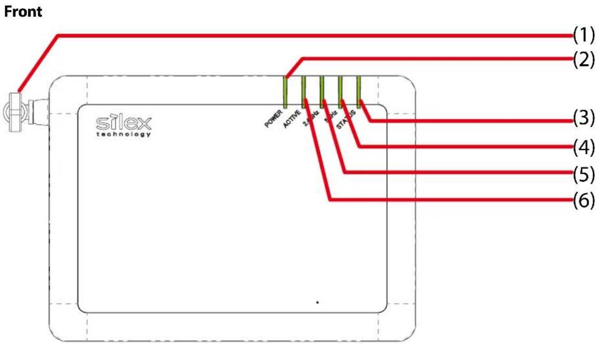
text_image
Front (1) (2) POWER ACTIVE 3.0Hz 5.0Hz STATUS (3) (4) (5) (6) silex technology| (1) | Wireless LAN Antenna | Wireless antenna for wireless communication | ||
| (2) | POWER LED(Green/Orange/Red) | Green ON | N Powering on | |
| Red Blink | USB storage error | |||
| Blink rapidly USB over current | ||||
| (3) | STATUS LED(Green/Red) | Green ON | N Smart Wireless Setup is completed (* Turns off in 3 mins) | |
| Blink Smart Wireless Setup is in progress | ||||
| Red ON | Smart Wireless Setup failed (* Turns off in 3 mins)(Timeout/Overlap error occur) | |||
| Blink rapidly Smart Wireless Setup (PIN code method) failed (* Blinks for 1 sec) | ||||
| Blink Updating firmware | ||||
| (4) | 5GHz LED(Green/Orange/Red) | Green ON | ON One or more 5GHz wireless interfaces are active | |
| Blink Communicating over a wireless LAN | ||||
| OFF 5GHz wireless interface is not active. | ||||
| Orange ON Host AP is connected by WDS | ||||
| Red ON | DFS in progress (communication is disabled then) (* Turns off in 1 min) | |||
| (5) | 2.4GHz LED(Green/Orange/Red) | Green ON | ON One or more 2.4GHz wireless interfaces are active | |
| Blink Communicating over a wireless LAN | ||||
| OFF 2.4GHz wireless interface is not active. | ||||
| Orange ON Host AP is connected by WDS | ||||
| (6) | ACTIVE LED(Green/Orange/Red) | Green ON Ready | ||
| Orange Blink Running in Configuration Mode | ||||
| Red Blink Configuration Mode error | ||||
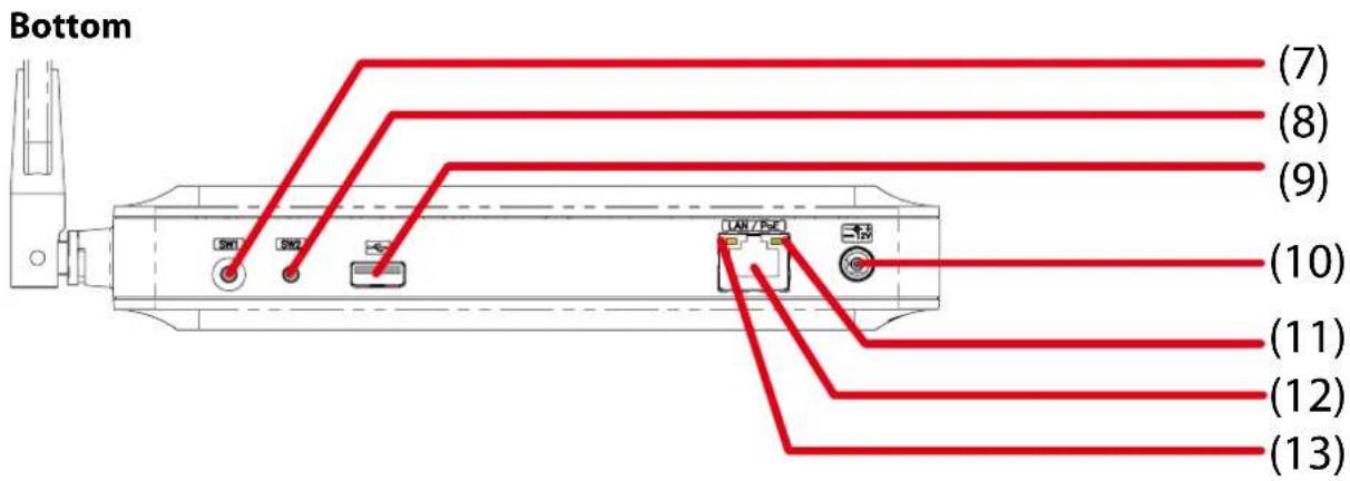
text_image
Bottom (7) (8) (9) (10) (11) (12) (13)| (7) | Push Switch (SW1) | When pressed together with the one on your wireless device while AP-500AC is active, wireless configuration can be performed. (Smart Wireless Setup) | |
| (8) | Push Switch (SW2) | Start inConfiguration Mode | Press and hold this switch for more than 3 sec while AP-500AC is active. |
| Factory default configuration | Press and hold this switch while turning on AP-500AC. Release the switch in 2 sec or more after Link LED and Status LED turn on. | ||
| (9) | USB Port Connect a USB cable (A-type connector). | ||
| (10) | AC Connector Connect an AC adaptor. | ||
| (11) | Link LED (Green) Turns on when connected to a wired LAN. | ||
| (12) | Network Port Connect a network cable. | ||
| (13) | Status LED (Yellow) Blinks while communicating in a wired LAN. | ||
Back
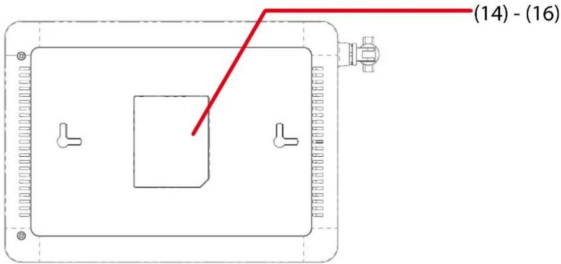
text_image
(14) - (16)| (14) Default | |
| SSID (2.4GHz/5GHz) | SSID of 2.4GHz/5GHz (default value) |
| Key | Network key (default value) |
| PIN Code | Authentication mode (default value) |
| Authentic | Encryption mode (default value) |
| Encryption | PIN code (default value) |
| Password | Login password (default value) |
| IP Address | IP Address (default value) |
| (15) E/A Ethernet Address | |
| (16) $/N Serial Number | |
2-3. Hardware Specification
| Operating environment Temp | perature: +0 C to +40 C, +32 F to +104 F |
| Humidity: 20% to 80%RH (Non-condensing) | |
| Storage environment Temp | ature: -10 C to +50 C, +14 F to +122 F |
| Humidity: 20% to 90%RH (Non-condensing) | |
| EMI VCCI Class B | FCC Part15 SubPart B Class BEN55022, EN301489-1/-17ICES-003 Class B |
| CPU 32bit RISC CPU | |
| Memory RAM: 256MByte | |
| ROM: 16MByte | |
| eMMC: 4GByte | |
| Wired network interface 10BA | SE-T/100BASE-TX/1000BASE-T(Auto-sensing): 1 portAuto MDI/MDIXPower over Ethernet PoE |
| Wireless network interface IEEE | 802.11a/b/g/n/ac(For channels you can use, check the regulations in your country.) |
| Antenna Non-directional antenna | |
| USB interface USB2.0 Hi-Speed port (A type): 1 port | |
| Push Switch 2 For Smart Wireless Setup: 1For Configuration Mode/Factory default configuration: 1 | |
| LED Front POWER LED (Green/Orange/Red) | |
FCC / IC Notice
FC
Channel Selection
For product available in the USA/Canada market, only channel 1\~11 can be operated. Selection of other channels is not possible.
Fcc Rules Part 15
FCC CAUTION
Changes or modifications not expressly approved by the party responsible for compliance could void the user's authority to operate the equipment.
2.4GHz device
FCCID : N6C-SXPCEGN
IC:4908B-SXPCEGN
This equipment has been tested and found to comply with the limits for a Class B digital device, pursuant to part 15 of the FCC Rules. These limits are designed to provide reasonable protection against harmful interference in a residential installation. This equipment generates, uses and can radiate radio frequency energy and, if not installed and used in accordance with the instructions, may cause harmful interference to radio communications. However, there is no guarantee that interference will not occur in a particular installation. If this equipment does cause harmful interference to radio or television reception, which can be determined by turning the equipment off and on, the user is encouraged to try to correct the interference by one or more of the following measures:
- Reorient or relocate the receiving antenna.
- Increase the separation between the equipment and receiver.
- Connect the equipment into an outlet on a circuit different from that to which the receiver is connected.
- Consult the dealer or an experienced radio/TV technician for help.
This device complies with part 15 of the FCC Rules. Operation is subject to the following two conditions:
(1) This device may not cause harmful interference, and
(2) this device must accept any interference received, including interference that may cause undesired operation.
This device complies with Industry Canada's licence-exempt RSSs. Operation is subject to the following two conditions:
(1) This device may not cause interference; and
(2) This device must accept any interference, including interference that may cause undesired operation of the device.
Below sentences must be indicated on the final product which contains this module inside.
This device complies with Part 15 of FCC Rules and Industry Canada licence-exempt RSS standard(s). Operation is subject to the following two conditions: (1) this device may not cause interference, and (2) this device must accept any interference, including interference that may cause undesired operation of this device.
This equipment complies with FCC/IC radiation exposure limits set forth for an uncontrolled environment and meets the FCC radio frequency (RF) Exposure Guidelines and RSS-102 of the IC radio frequency (RF) Exposure rules. This equipment should be installed and operated keeping the radiator at least 20cm or more away from person's body.
Compliance with FCC requirement 15.407(c)
Data transmission is always initiated by software, which is the passed down through the MAC, through the digital and analog baseband, and finally to the RF chip. Several special packets are initiated by the MAC. These are the only ways the digital baseband portion will turn on the RF transmitter, which it then turns off at the end of the packet. Therefore, the transmitter will be on only while one of the aforementioned packets is being transmitted.
In other words, this device automatically discontinue transmission in case of either absence of information to transmit or operational failure.
FCC Rules Part 15 Subpart E §15.407(g)
Frequency Tolerance: +/-20 ppm
FCC Rules Part 15 Subpart C §15.247(g) / Subpart E
This device and its antenna(s) must not be co-located or operation in conjunction with any other antenna or transmitter.
RSS-Gen §8.3
This radio transmitter 4908A-SXPCEAC has been approved by Industry Canada to operate with the antenna types listed below with the maximum permissible gain and required antenna impedance for each antenna type indicated. Antenna types not included in this list, having a gain greater than the maximum gain indicated for that type, are strictly prohibited for use with this device.
5150-5250 MHz and 5250-5350 MHz bands are restricted to indoor operations only.
High-power radars are allocated as primary users (i.e. priority users) of the bands 5250-5350 MHz and 5650-5850 MHz and that these radars could cause interference and/or damage to LE-LAN devices.
The FCC / The Industry Canadaregulations provide that changes or modifications not expressly approved by the party responsible for compliance could void the user's authority to operate the equipment.
CE Notice
CE①
2-4. Software Specification
| TCP/IP Network | k layer ARP, IP, ICMP | |
| Transport layer TCP, UDP | ||
| Application layer BOOTP, | DHCP(Client/Server), HTTP, WINS(NBNS),NTP, SNMP, SSH, JCP(Silex proprietary protocol),SXUPTP(Silex proprietary protocol), SX-KeepAlive(Silex proprietary protocol),SXSMP(Silex proprietary protocol) |
2-5. Power Supply
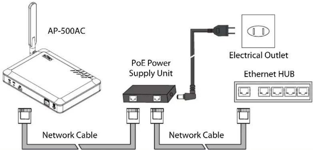
AP-500AC can receive electrical power via a AC adaptor or network cable.
AP-500AC can receive electrical power from the IEEE802.3af compliant power supply unit over a network cable. For details, please see the operating manual that came with your power supply devices.

Note
- PoE is a technology to supply electrical power over Ethernet cable (Category 5 or above). This technology allows you to connect your PoE supported devices to the Ethernet even in a location without electrical outlet nearby.

TIP
- When receiving power over Ethernet, you do not have to use the AC adaptor that came with AP-500AC.
- Please remember that power is supplied from the AC adaptor if it is connected to AP-500AC.
Sample connection1: When using a PoE supported HUB
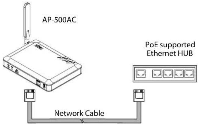
text_image
AP-500AC PoE supported Ethernet HUB Network CableSample connection2: When using a PoE power supply unit
flowchart
graph TD
    A["AP-500AC"] --> B["Network Cable"]
    A --> C["PoE Power Supply Unit"]
    C --> D["Electrical Outlet"]
    C --> E["Ethernet HUB"]
    C --> F["Network Cable"]
2-6. Wireless Interference Information
Notes
Do not use AP-500AC near the following devices or places.
- Microwave, pacemaker, etc. of industrial, scientific and medical devices
- Licensed radio station in a factory
- Small power radio station (A non-licensed radio station)
These devices may use the same band. If you use AP-500AC near these devices, the radio waves emitted from AP-500AC may interfere with them.
Do not use AP-500AC near a cellular phone, TV or Radio.
A cellular phone, TV and radio use a different radio band than our products. Generally, if they are used near AP-500AC, it will not cause any problems. However, when they approximate AP-500AC, sound or image noise may occur.
If there is reinforced concrete/metal between wireless devices, they may not connect.
AP-500AC can connect through wood or glass, but may have troubles connecting through reinforced concrete/metal.
AP-500AC complies with the certification of conformance to technical standards. Please pay attention to the following points:
- Please do not disassemble or remodel the product. Such action is prohibited by law.
- Please do not remove the certificate label. Using the product without a label is prohibited.
Wireless devices using 2.4GHz band
The same frequency band of AP-500AC is used for a microwave, industry, science, medical equipment and licensed in room or low power (non-licensed) radio stations.
- Before you use AP-500AC, check that it does not interfere with other devices.
- If interference occurs, stop using AP-500AC or change the wireless band. Please consider to create a wall between these devices to avoid interference. Contact us to for possible solution.
* The meaning of the symbols in the bottom of the unit:
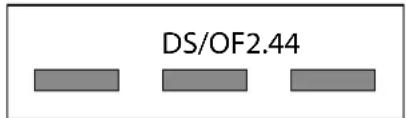
text_image
DS/OF2.442.4 : Wireless devices using 2.4GHz frequency band
DS/OF : DS-SS or OFDM is used as modulation.
4: The range of interference is equal to or lower than 40m.

Notes on using 5GHz band
- Use of 5.2GHz band (W52) and 5.3GHz band (W53) outdoors is prohibited by the radio regulations.
DFS
AP-500AC supports DFS (Dynamic Frequency Selection) of the IEEE 802.11h wireless standard. When radar signals are detected, the channel will automatically be switched to avoid interference with radar systems (e.g. weather radar, etc).
One alternative channel can individually be set for W53/W56 channels beforehand, which will be used when radar signals are detected and the channel needs to be switched.
When alternative channels are not specified or radar signals are detected even for that channel, AP-500AC switches the channel in order of the following:
DFS Channels (5GHz band)
| W53 HT20/VHT20 52 > 56 > 60 > 64 > 36 | ||
| HT40/VHT40 + 52 > 60 > 36 | ||
| VHT80 36 | ||
| W56 HT20/VHT20 100 > 104 > 108 > 112 > 116 > 120 > 124 > 128 > 132 > 136 > 140 | ||
| HT40/VHT40 + 100 > 108 > 116 > 124 > 132 | ||
| VHT80 100 > 116, 104 > 120, 108 > 124, 112 > 128, 116 > 100, 120 > 104, 124 > 108, 128 > 112 | ||

- AP-500AC checks if there are radar signals on the DFS channels when it is powered on. During this time, no wireless communication is allowed to AP-500AC.
- If radar signals are detected during or after AP-500AC is powered on, the channel needs to be changed in order to avoid wireless interference. Therefore, if DFS channels are selected, the channel could be changed automatically.
- The radar signals are monitored for a certain amount of time (*) after it is detected, while wireless communication is disabled on AP-500AC then. Once radar signals are detected, the channel will not be available for 30 mins. (* This time period differs depending on the country.)
2-7. Notes on Security
Because a wireless LAN uses electromagnetic signals instead of a network cable to establish communication with network devices, it has the advantage of allowing devices to connect to the network easily. However, a disadvantage of this is that within a certain range, the electromagnetic signals can pass through barriers such as walls, and if security countermeasures are not implemented in some way, problems such as the following may occur.
- Communication is intercepted by a third party
- Unauthorized access to the network
- Leakage of personal information (ID and Card information)
- Spoofing and the falsification of intercepted data
- System crashes and data corruption
Nowadays, wireless LAN cards or access points are equipped with security measures that address such security problems, so that you can enable security-related settings for wireless LAN products in order to reduce the likelihood of problems occurring.
We recommend that you make yourself fully acquainted with the possible implications of what might happen if you use a wireless product without enabling security features, and that you configure security-related settings and use wireless products at your own responsibility.
2-8. OpenSSL License
This product includes software developed by the OpenSSL Project for use in the OpenSSL Toolkit. (http://www.openssl.org/)
OpenSSL License
/*
* Copyright (c) 1998-2005 The OpenSSL Project. All rights reserved.
*
* Redistribution and use in source and binary forms, with or without
* modification, are permitted provided that the following conditions
* are met:
*
* 1. Redistributions of source code must retain the above copyright
* notice, this list of conditions and the following disclaimer.
*
* 2. Redistributions in binary form must reproduce the above copyright
* notice, this list of conditions and the following disclaimer in
* the documentation and/or other materials provided with the
* distribution.
*
* 3. All advertising materials mentioning features or use of this
* software must display the following acknowledgment:
* "This product includes software developed by the OpenSSL Project
* for use in the OpenSSL Toolkit. (http://www.openssl.org/)
*
* 4. The names "OpenSSL Toolkit" and "OpenSSL Project" must not be used to
* endorse or promote products derived from this software without
* prior written permission. For written permission, please contact
* openssl-core@openssl.org.
*
* 5. Products derived from this software may not be called "OpenSSL"
* nor may "OpenSSL" appear in their names without prior written
* permission of the OpenSSL Project.
*
* 6. Redistributions of any form whatsoever must retain the following
* acknowledgment:
* "This product includes software developed by the OpenSSL Project
* for use in the OpenSSL Toolkit (http://www.openssl.org/)
* THIS SOFTWARE IS PROVIDED BY THE OpenSSL PROJECT "AS IS" AND ANY
* EXPRESSED OR IMPLIED WARRANTIES, INCLUDING, BUT NOT LIMITED TO, THE
* IMPLIED WARRANTIES OF MERCHANTABILITY AND FITNESS FOR A PARTICULAR
* PURPOSE ARE DISCLAIMED. IN NO EVENT SHALL THE OpenSSL PROJECT OR
* ITS CONTRIBUTORS BE LIABLE FOR ANY DIRECT, INDIRECT, INCIDENTAL,
* SPECIAL, EXEMPLARY, OR CONSEQUENTIAL DAMAGES (INCLUDING, BUT
* NOT LIMITED TO, PROCUREMENT OF SUBSTITUTE GOODS OR SERVICES;
* LOSS OF USE, DATA, OR PROFITS; OR BUSINESS INTERRUPTION)
* HOWEVER CAUSED AND ON ANY THEORY OF LIABILITY, WHETHER IN CONTRACT,
* STRICT LIABILITY, OR TORT (INCLUDING NEGLIGENCE OR OTHERWISE)
* ARISING IN ANY WAY OUT OF THE USE OF THIS SOFTWARE, EVEN IF ADVISED
* OF THE POSSIBILITY OF SUCH DAMAGE.
*
*
* This product includes cryptographic software written by Eric Young
* (eay@cryptsoft.com). This product includes software written by Tim
* Hudson (tjh@cryptsoft.com).
*
*/
Original SSLeay License
/* Copyright (C) 1995-1998 Eric Young (eay@cryptsoft.com)
* All rights reserved.
*
* This package is an SSL implementation written
* by Eric Young (eay@cryptsoft.com).
* The implementation was written so as to conform with Netscapes SSL.
*
* This library is free for commercial and non-commercial use as long as
* the following conditions are aheared to. The following conditions
* apply to all code found in this distribution, be it the RC4, RSA,
* Ihash, DES, etc., code; not just the SSL code. The SSL documentation
* included with this distribution is covered by the same copyright terms
* except that the holder is Tim Hudson (tjh@cryptsoft.com).
*
* Copyright remains Eric Young's, and as such any Copyright notices in
* the code are not to be removed.
* If this package is used in a product, Eric Young should be given attribution
* as the author of the parts of the library used.
* This can be in the form of a textual message at program startup or
* in documentation (online or textual) provided with the package.
* Redistribution and use in source and binary forms, with or without
* modification, are permitted provided that the following conditions
* are met:
* 1. Redistributions of source code must retain the copyright
* notice, this list of conditions and the following disclaimer.
* 2. Redistributions in binary form must reproduce the above copyright
* notice, this list of conditions and the following disclaimer in the
* documentation and/or other materials provided with the distribution.
* 3. All advertising materials mentioning features or use of this software
* must display the following acknowledgement:
* "This product includes cryptographic software written by
* Eric Young (eay@cryptsoft.com)"
* The word 'cryptographic' can be left out if the rouines from the library
* being used are not cryptographic related :-).
* 4. If you include any Windows specific code (or a derivative thereof) from
* the apps directory (application code) you must include an acknowledgement:
* "This product includes software written by Tim Hudson (tjh@cryptsoft.com)"
*
* THIS SOFTWARE IS PROVIDED BY ERIC YOUNG "AS IS" AND
* ANY EXPRESS OR IMPLIED WARRANTIES, INCLUDING, BUT NOT LIMITED TO, THE
* IMPLIED WARRANTIES OF MERCHANTABILITY AND FITNESS FOR A PARTICULAR PURPOSE
* ARE DISCLAIMED. IN NO EVENT SHALL THE AUTHOR OR CONTRIBUTORS BE LIABLE
* FOR ANY DIRECT, INDIRECT, INCIDENTAL, SPECIAL, EXEMPLARY, OR CONSEQUENTIAL
* DAMAGES (INCLUDING, BUT NOT LIMITED TO, PROCUREMENT OF SUBSTITUTE GOODS
* OR SERVICES; LOSS OF USE, DATA, OR PROFITS; OR BUSINESS INTERRUPTION)
* HOWEVER CAUSED AND ON ANY THEORY OF LIABILITY, WHETHER IN CONTRACT, STRICT
* LIABILITY, OR TORT (INCLUDING NEGLIGENCE OR OTHERWISE) ARISING IN ANY WAY
* OUT OF THE USE OF THIS SOFTWARE, EVEN IF ADVISED OF THE POSSIBILITY OF
* SUCH DAMAGE.
*
* The licence and distribution terms for any publicly available version or
* derivative of this code cannot be changed. i.e. this code cannot simply be
* copied and put under another distribution licence
* [including the GNU Public Licence.]
*/
3. Configuration Using Web Page
This chapter explains how to configure AP-500AC.
3-1. Displaying Web Page of AP-500AC (Initial Configuration)
AP-500AC settings can be configured from its Web page.
When AP-500AC has default setting, the Web page can be displayed by the following methods. Display the Web page using a method appropriate for your environment.
Using a wired LAN
Connect AP-500AC and PC via a wired LAN to display the Web page. It is possible to connect two or more AP-500AC units to a wired LAN to configure them at once. Start from this when you connect AP-500AC to your existing wired LAN.
Configuration Mode
Connect AP-500AC directly to PC using a network cable to display the Web page. AP-500AC can be configured one by one.
Using a wireless LAN
Connect AP-500AC (running as Access Point) from PC wirelessly to display the Web page.
Smart Wireless Setup
Connect AP-500AC and PC by Smart Wireless Setup to display the Web page.
Using external registrar
Connect AP-500AC and PC using Set Up a Network of Windows to display the Web page.
Displaying Web Page Using Wired LAN
Connect AP-500AC and PC via a wired LAN to display the Web page. It is possible to connect two or more AP-500AC units to a wired LAN to configure them at once. Start from this when you connect AP-500AC to your existing wired LAN.
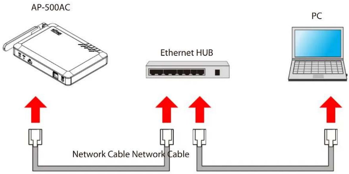
flowchart
graph TD
    A["AP-500AC"] --> B["Network Cable Network Cable"]
    C["Ethernet HUB"] --> B
    D["PC"] --> E["Network Cable Network Cable"]
    style A fill:#f9f,stroke:#333
    style C fill:#ccf,stroke:#333
    style D fill:#cfc,stroke:#333
Following items are required:
- PC to use for configuration
- Network Cable
- Ethernet HUB
(When receiving power over Ethernet (PoE), PoE Hub or PoE power supply unit is required.)

- When there are available LAN ports on the network in which AP-500AC is to be installed, you do not have to purchase a new Ethernet Hub or broadband router as AP-500AC can be connected to the available LAN port.
- Connect the PC (to use for setup) and Ethernet Hub using a network cable.
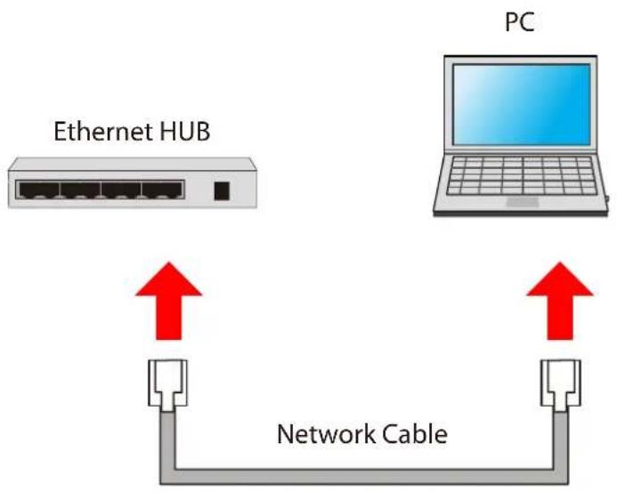
flowchart
graph TD
    A["Ethernet HUB"] -->|Red Up arrow| B["Network Cable"]
    C["PC"] -->|Red Up arrow| B
    B --> D["Gray Wire Link"]
    style A fill:#f9f,stroke:#333
    style C fill:#ccf,stroke:#333
    style B fill:#cfc,stroke:#333
    style D fill:#fcc,stroke:#333
- Check the IP Address of AP-500AC.
The default IP Address can be found on the bottom label of AP-500AC.
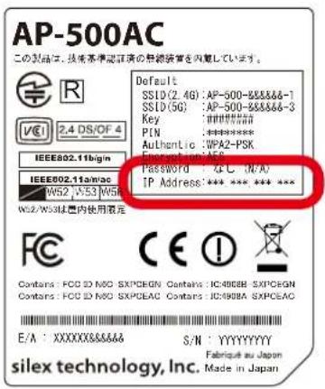
text_image
AP-500AC この製品は、技術基本認証書の最終装備を内蔵しています。 Default SSID (2.4G): AP-500-8888&-1 SSID (5G): AP-500-8888&-3 Key: ###### P/N: ****** Authentic: UWPA2-PSK IEEE802.11b/g/n IEEE802.11a/mac W52 1/53 W5R W52/W53は室内使用限定 Password: *C: IN/A/ IP Address: *** *** *** *** CE I Contains: FCD ID NO SXPCEGN Contains: IC490BB SXPCEGN Contains: FCD ID NO SXPCEAC Contains: IC490BA SXPCEAC E/A : XXXXXX&&&&S S/N : YYYYYYY silex technology, Inc. Fabrique au Japan Made in Japan
- If AP-500AC was configured for another network in the past and you are not sure what IP Address has been assigned, reset AP-500AC to factory defaults. For how to initialize AP-500AC, refer to Chapter 5-11 Maintenance Feature - Factory Default Configuration.
3. Connect AP-500AC and Ethernet Hub via a network cable.
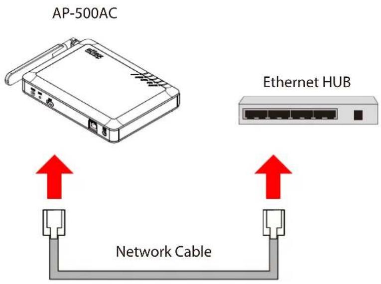
text_image
AP-500AC Ethernet HUB Network Cable4. Connect the AC adapter to AP-500AC and AC plug to a power outlet.
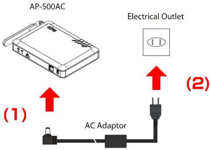
text_image
AP-500AC Electrical Outlet (1) AC Adaptor (2)
- When receiving a power over Ethernet (PoE), the AC adaptor does not need to be connected.
Make sure that the PoE supported HUB or PoE power supply unit is used then.
- To connect two or more AC-500AP units, repeat the process at 2-4.
- Change the network settings on the PC to access AP-500AC.
Example:
In case the default IP Address of AP-500AC is 10.18.52.86, change the network settings on your PC to the following:
- IP Address : 10.1.2.3
- Subnet Mask : 255.0.0.0

Note
- Please be sure to set a unique address to your PC, that is not used for AP-500AC.
- Start a Web browser (Internet Explorer, Firefox, etc) on the PC you are using for the setup, enter the IP address of AP-500AC in the address bar and press the ENTER key.
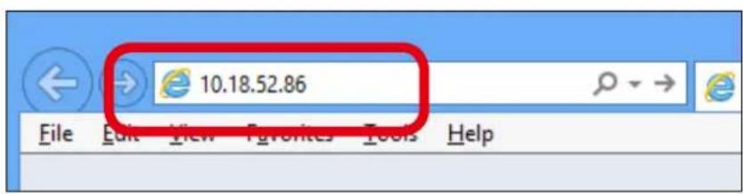
text_image
10.18.52.86 File Edit View Favorites Tools Help
Note
- By using the device search utility "AMC Finder" that can be downloaded from our homepage, it is possible to show all AP-500AC units as a list and access the Web page of each. For how to install and use AMC Finder, refer to 5-12. Product Search Utility.
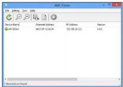
text_image
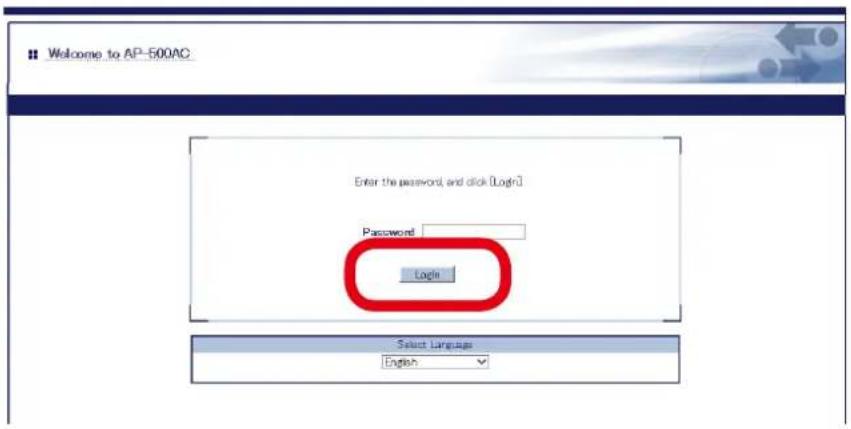
AMC Finder File Edit Tools Help Device Name Ethernet Address IP Address Version AP-500AC 84.25 SF 12:34:56 192.88.20.123 1.0.0 f device(s) are found.- The login menu window is displayed. Click Login to login to the Web page.
text_image
Welcome to AP-500AC Enter the password, and click [Login] Password Login Select Language English
- No password is set by default. In such case, just click Login.
Note
Web page has been displayed. Go on to 3-3. Configuration at Web Page.
Displaying Web Page Using Configuration Mode
Connect AP-500AC directly to PC using a network cable to display the Web page. AP-500AC can be configured one by one.
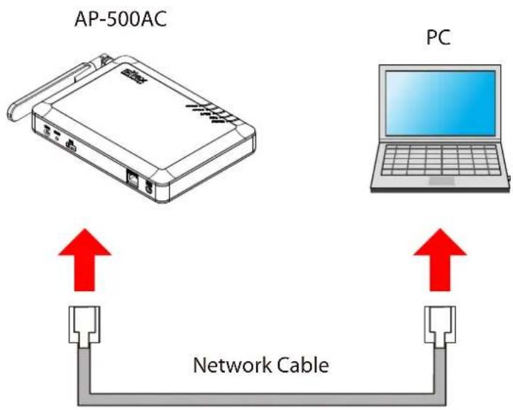
flowchart
graph TD
    A["AP-500AC"] -->|Red Up arrow| B["Network Cable"]
    C["PC"] -->|Red Up arrow| B
    B --> D["Output"]
    style A fill:#f9f,stroke:#333
    style C fill:#ccf,stroke:#333
    style B fill:#cff,stroke:#333
Following items are required:
- PC to use for configuration
- Network Cable
- If a wireless interface is enabled on the PC (to use for configuration), please disable it temporarily.

Note
- If a wireless interface is enabled on the PC, the Web page may not be displayed.
- Connect AP-500AC and the PC (to use for setup) using a network cable.
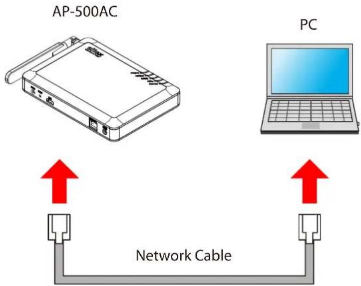
flowchart
graph TD
    A["AP-500AC"] -->|Red Arrow Down| B["Network Cable"]
    C["PC"] -->|Red Arrow Up| B
    B --> D["Red Arrow Up"]
    style A fill:#f9f,stroke:#333
    style C fill:#ccf,stroke:#333
    style B fill:#cff,stroke:#333
- Connect the AC adapter to AP-500AC, and the AC adapter's plug to an electrical outlet.
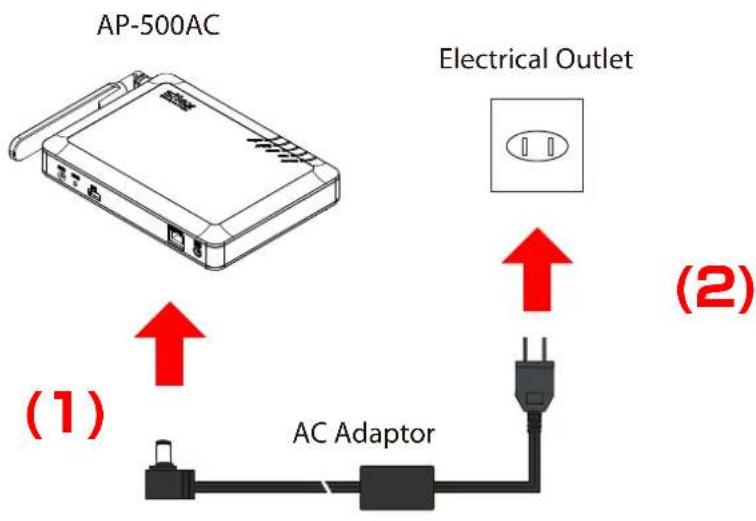
text_image
AP-500AC Electrical Outlet (1) AC Adaptor (2)- When the front ACTIVE LED starts blinking in Green and then turns on to Green, press and hold the push switch with a fine tipped object such as a pen or pencil.
Release the push switch (SW2) when ACTIVE LED starts blinking in Orange (It may take 3sec until blinking).
AP-500AC will start running in the Configuration Mode and you will be ready to configure AP-500AC from the PC.
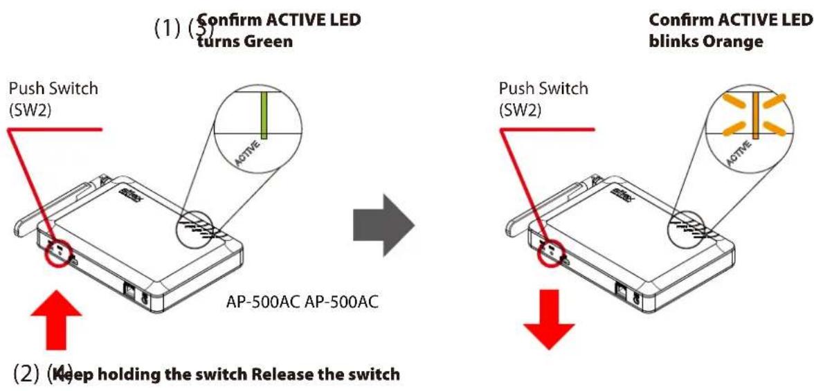
text_image
(1) Confirm ACTIVE LED turns Green Push Switch (SW2) ACTIVE AP-500AC AP-500AC Confirm ACTIVE LED blinks Orange Push Switch (SW2) ACTIVE (2) Keep holding the switch Release the switch- Start a Web browser (Internet Explorer, Firefox, etc) on the PC you are using for the setup. The Web page of AP-500AC is displayed.
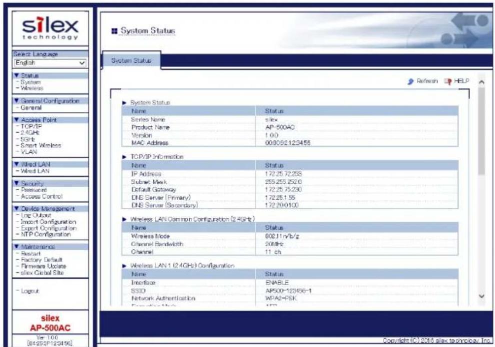
text_image
silex technology Select Language English Status - System - Wireless General Configuration - General Access Point - TCP/IP - 2.4GHz - Sqrtb - Smart Wireless - VLAN Wired LAN - Wired LAN Security - Password - Access Control Device Management - Log Output - Import Configuration - Export Configuration - NTP Configuration Maintenance - Restart - Factory Default - Firmware Update - silex Global Site Logout silex AP-500AC Ver 100 [8425SF12S4196] System Status: Name Status Series Name silex Product Name AP-500AC Version 1.00 MAC Address 000092123455 TCP/IP Information Name Status IP Address 172.25.72.253 Subset Mask 255.255.2520 Default Gateway 172.25.75.230 DNS Server (Primary) 172.25.1.55 DNS Server (Secondary) 172.20.0100 Wireless LAN Common Configuration (2.4GHz) Name Status Wireless Mode 602.11nVb/g Channel Bandwidth 20MHz Channel 11 ch Wireless LAN 1 (2.4GHz) Configuration Name Status Interface ENABLE SSID AP500-123456-1 Network Authentication WPA2-PSK Executive Mode CSP System Status: Refresh HELP Copyright © 2016 silex technology, Inc.
Note
- If the Web page is not displayed, enter "http://silex" in the address bar of the Web browser and press the Enter key.
- If a password is set to AP-500AC, a password entry screen is displayed. Enter the password and click Login.
- The password entry screen is not displayed at the initial setup.
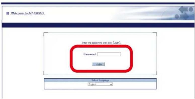
text_image
Welcome to AP-500AC Enter the password and click [Login] Password Login Select Language EnglishWeb page has been displayed. Go on to 3-3. Configuration at Web Page.
Displaying Web Page Using Wireless LAN
Connect AP-500AC and PC wirelessly to display the Web page.
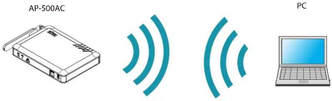
Following items are required:
- PC to use for configuration

- By default, it is impossible to access Web page as the port filter setting denies HTTP access over a wireless LAN. To use this method, change the port filter setting in advance to allow HTTP access over a wireless LAN.
1. Check the SSID, security key and IP Address of AP-500AC.
The default values can be found on the bottom label of AP-500AC.
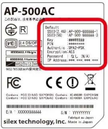
text_image
AP-500AC この製品は、技術基本証書 Default SSID(2.4G):AP-500-XXXXXX-1 SSID(9G):AP-500-XXXXXX-3 Key :###### P/N :###### Authentic :UPX2-PSK Encryption: AES Password:なし (N/A) IP Address:###,###,### W52/5x3 W52/5x3 W52/WS3は国内使用測定 CE! Contains: FCD ID N60-SXP/CEAN Contains: IC498BB-SXP/CRON Contains: FCD ID N60-SXP/CEAC Contains: ICP29BA-SXP/CEAC E/A :XXXXXXXX&&&&S S/N : YYYYYYYYY Fabrique au Japan silex technology, Inc. Made in Japan
- If AP-500AC was configured for another network in the past and you are not sure what IP Address has been assigned, reset AP-500AC to factory defaults. For how to initialize AP-500AC, refer to Chapter 5-11 Maintenance Feature - Factory Default Configuration.
2. Connect the AC adapter to AP-500AC, and the AC adapter's plug to an electrical outlet.
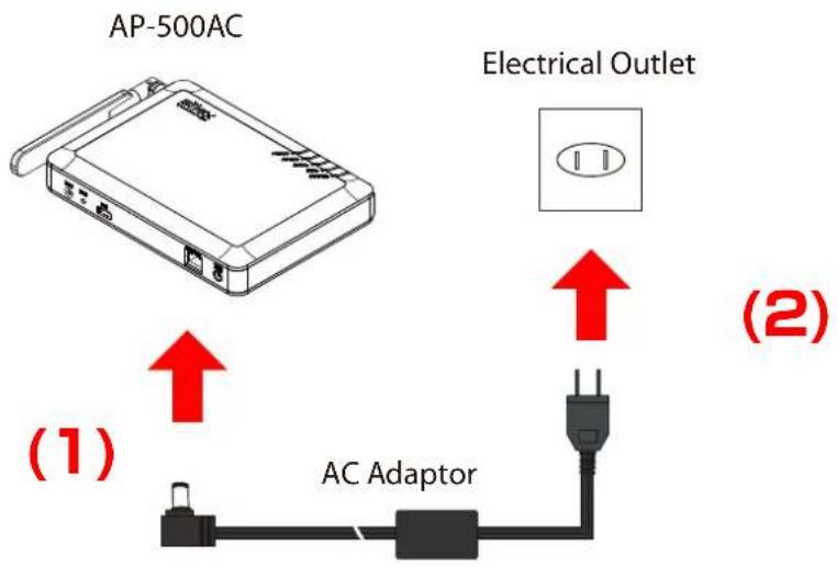
text_image
AP-500AC Electrical Outlet (1) AC Adaptor (2)- Move your cursor to top-right or bottom right corners (when a touch-panel device is used, swipe your finger from the right edge) and click Settings from the charm bar.

text_image
Settings- Click the icon below to show the wireless connection window.

text_image
Available- Select the SSID configured on AP-500AC from a list and click Connect.
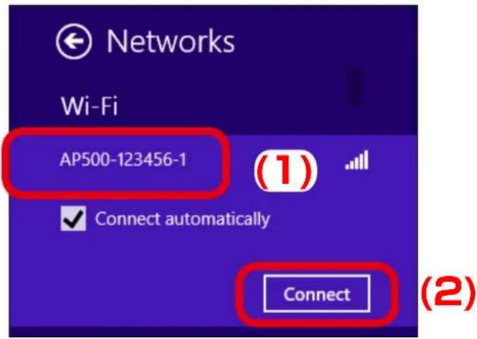
text_image
Networks Wi-Fi AP500-123456-1 Connect automatically Connect (1) (2)
Note
- When Connect automatically is checked, the PC will automatically be connected when it is restarted next time.
- Enter the security key of AP-500AC for Enter the network security key and click Next.
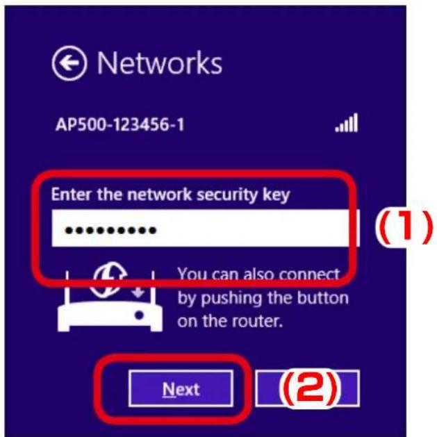
text_image
Networks AP500-123456-1 Enter the network security key You can also connect by pushing the button on the router. Next (2)7. Click No, don't turn on sharing or connect to devices.
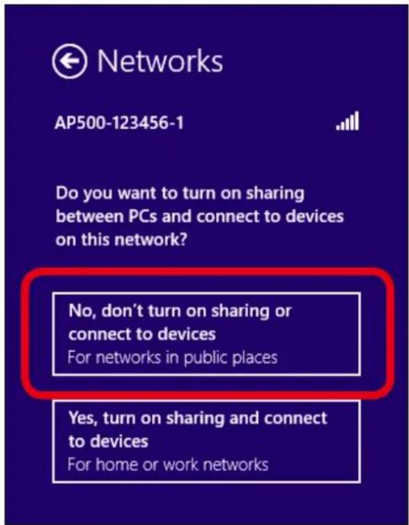
text_image
Networks AP500-123456-1 Do you want to turn on sharing between PCs and connect to devices on this network? No, don't turn on sharing or connect to devices For networks in public places Yes, turn on sharing and connect to devices For home or work networks8. Change the network settings on the PC to access AP-500AC.
Example:
In case the default IP Address of AP-500AC is 10.18.52.86, change the network settings on your PC to the following:
- IP Address : 10.1.2.3
- Subnet Mask : 255.0.0.0

Note
- Please be sure to set a unique address to your PC, that is not used for AP-500AC.
- Start a Web browser (Internet Explorer, Firefox, etc) on the PC you are using for the setup, enter the IP address of AP-500AC in the address bar and press the ENTER key.
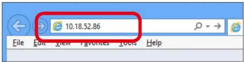
text_image
10.18.52.86 File Edit View Favorites Tools Help
- By using the device search utility "AMC Finder" that can be downloaded from our homepage, it is possible to show all AP-500AC units as a list and access the Web page of each. For how to install and use AMC Finder, refer to 5-12. Product Search Utility.
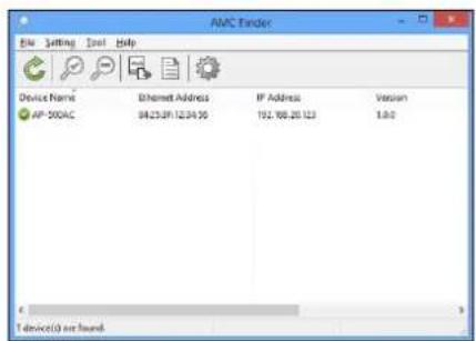
text_image
ANC Finder File Setting Tools Help Device Name Ethernet Address IP Address Vision AP-300AC 94.25.09.12.04.90 192.88.20.123 1.6.0 1 device(s) not found- The login menu window is displayed. Click Login to login to the Web page.
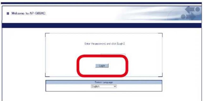
text_image
Welcome to AP-500AC Enter the password, and click [Login] Login Select Language English
- No password is set by default. In such case, just click Login.
Web page has been displayed. Go on to 3-3. Configuration at Web Page.
Displaying Web Page by Smart Wireless Setup
Use the Smart Wireless Setup switch (push switch SW1) to connect AP-500AC and PC via a wireless LAN as well as display the Web page.
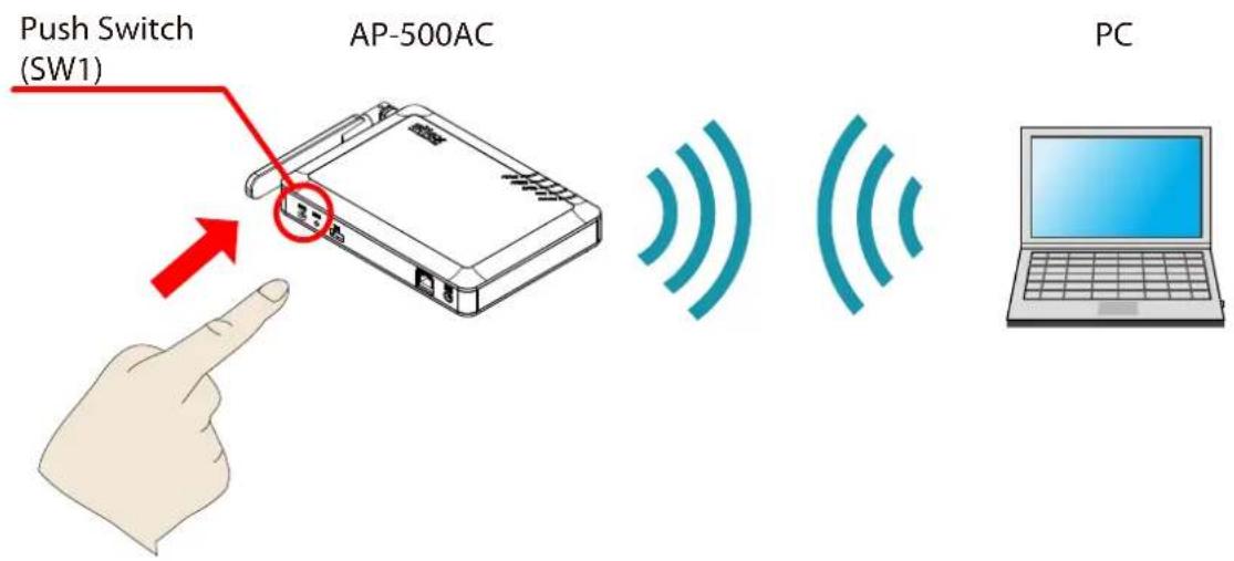
text_image
Push Switch (SW1) AP-500AC PCFollowing items are required:
- PC to use for configuration

- By default, it is impossible to access Web page as the port filter setting denies HTTP access over a wireless LAN. To use this method, change the port filter setting in advance to allow HTTP access over a wireless LAN.
- During this configuration, please place your PC closer to AP-500AC so that they can communicate better.
1. Check SSID(2.4GHz) and IP Address of AP-500AC.
The default values can be found on the bottom label of AP-500AC.
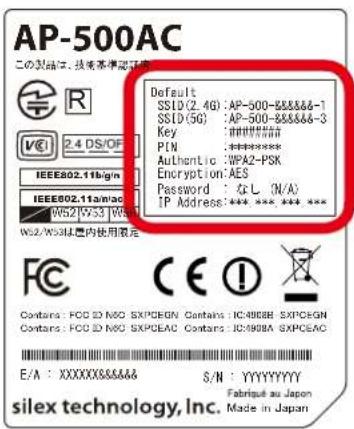
text_image
AP-500AC この製品は、技術基本準定証書 Default SSID(2.4G): AP-500-855566-1 SSID(5G): AP-500-855566-3 Key : ####### PIN : ****** Authentic : WFA2-PSK Encryption: AES Password : ▲ L (N/A) IP Address: *** *** *** *** W52/WS3A型内使用設定 FCC Contains: FCD ID NO: SXPCGN Contains: IC4908M SXPCGN Contains: FCD ID NO: SXPCAC Contains: IC4908M SXPCAC E/A : XXXXXX&&&& S/N : YYYYYYYY SILEX technology, Inc. Fabrié au Japon Made in Japan
Note
- By default, wireless interface 1 (2.4GHz) is set as wireless interface that can use Smart Wireless Setup.
- If AP-500AC was configured for another network in the past and you are not sure what IP Address has been assigned, reset AP-500AC to factory defaults. For how to initialize AP-500AC, refer to Chapter 5-11 Maintenance Feature - Factory Default Configuration.
2. Connect the AC adapter to AP-500AC, and the AC adapter's plug to an electrical outlet.
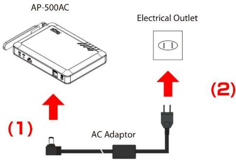
text_image
AP-500AC Electrical Outlet (1) AC Adaptor (2)- Move your cursor to top-right or bottom right corners (when a touch-panel device is used, swipe your finger from the right edge) and click Settings from the charm bar.
text_image
Settings- Click the icon below to show the wireless connection window.

text_image
Available- Select the SSID configured on AP-500AC from a list and click Connect.

text_image
Networks Wi-Fi AP500-123456-1 Connect automatically Connect (1) (2)
- When Connect automatically is checked, the PC will automatically be connected when it is restarted next time.
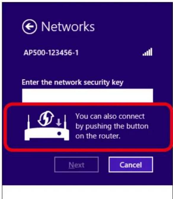
- The message says You can also connect by pushing the button on the router.
text_image
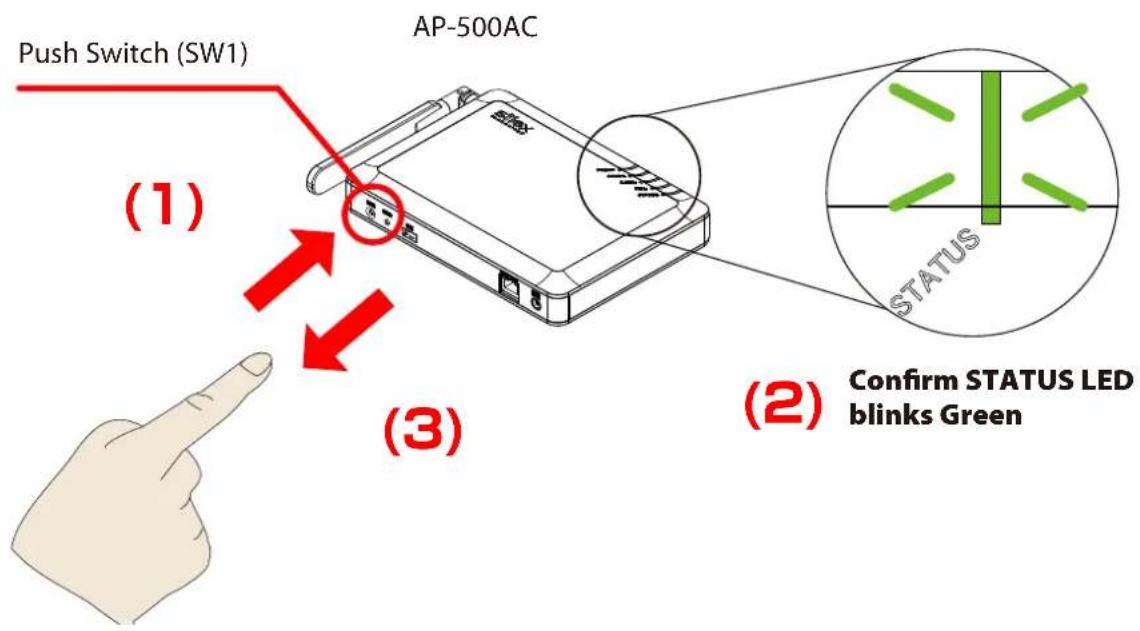
Networks AP500-123456-1 Enter the network security key You can also connect by pushing the button on the router. Next Cancel- Press and hold the push switch (SW1). Release it when STATUS LED start blinking in Green.
text_image
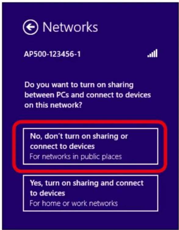
Push Switch (SW1) AP-500AC (1) (3) STATUS Confirm STATUS LED blinks Green- Click No, don't turn on sharing or connect to devices.
text_image
Networks AP500-123456-1 Do you want to turn on sharing between PCs and connect to devices on this network? No, don't turn on sharing or connect to devices For networks in public places Yes, turn on sharing and connect to devices For home or work networks9. Change the network settings on the PC to access AP-500AC.
Example:
In case the default IP Address of AP-500AC is 10.18.52.86, change the network settings on your PC to the following:
- IP Address : 10.1.2.3
- Subnet Mask : 255.0.0.0

Note
- Please be sure to set a unique address to your PC, that is not used for AP-500AC.
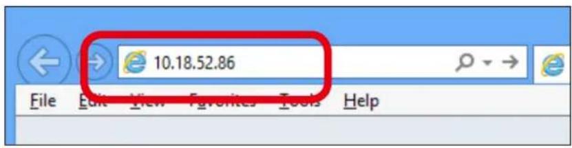
10. Start a Web browser (Internet Explorer, Firefox, etc) on the PC you are using for the setup, enter the IP address of AP-500AC in the address bar and press the ENTER key.
text_image
10.18.52.86 File Edit View Favorites Tools Help
Note
- By using the device search utility "AMC Finder" that can be downloaded from our homepage, it is possible to show all AP-500AC units as a list and access the Web page of each. For how to install and use AMC Finder, refer to 5-12. Product Search Utility.

text_image
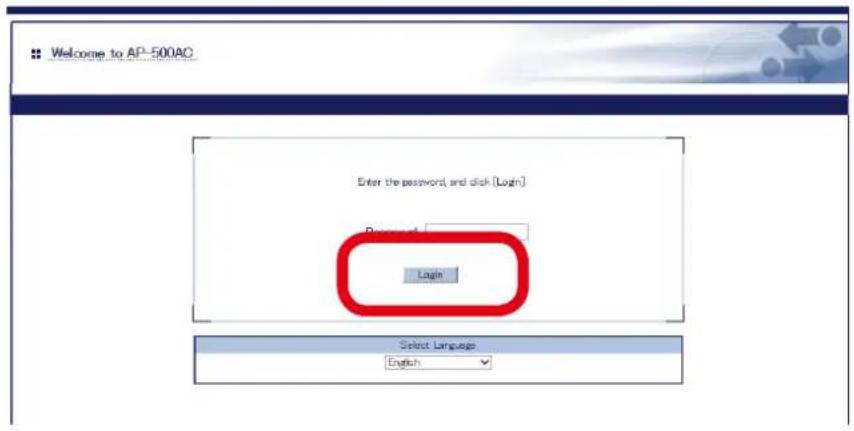
AMC Finder File Setting Tool Help Device Name Ethernet Address IP Address Vision AP-300&C 84.25.9F:12.36.96 192.165.20.123 1.0.0 1 device(s) are found.11. The login menu window is displayed.
Click Login to login to the Web page.
text_image
Welcome to AP-500AC Enter the password, and click [Login] Login Select Language English
- No password is set by default. In such case, just click Login.
Note
Web page has been displayed. Go on to 3-3. Configuration at Web Page.
Displaying Web Page Using External Registrar
Connect AP-500AC and PC using Set up a new connection or network of Windows 8 to display the Web page.
Following items are required:
- PC to use for configuration

- To continue this configuration, External Registrar must be set to ENABLE and Wireless LAN config status needs to be Unconfigured on AP-500AC. Before you begin, please check these settings at the Smart Wireless Setup page on the Web page.
-
By default, it is impossible to access Web page as the port filter setting denies HTTP access over a wireless LAN. To use this method, change the port filter setting in advance to allow HTTP access over a wireless LAN.
-
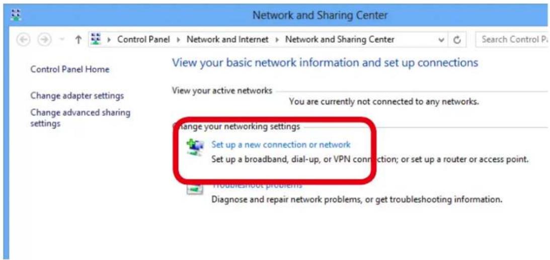
On the PC, go Control Panel and click Network and Internet - Network and Sharing Center and click Set up a new connection or network.
text_image
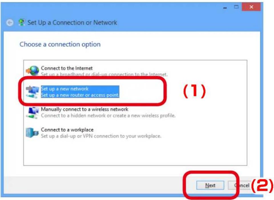
Network and Sharing Center Control Panel Home Change adapter settings Change advanced sharing settings View your basic network information and set up connections View your active networks You are currently not connected to any networks. Change your networking settings Set up a new connection or network Set up a broadband, dial-up, or VPN connection; or set up a router or access point. Troubleshoot problems Diagnose and repair network problems, or get troubleshooting information.2. Select Set up a new network and click Next.
text_image
Set Up a Connection or Network Choose a connection option Connect to the Internet Set up a broadband or dial-up connection to the Internet. (1) Set up a new network Set up a new router or access point. Manually connect to a wireless network Connect to a hidden network or create a new wireless profile. Connect to a workplace Set up a dial-up or VPN connection to your workplace. Next Cancel (2)3. Select AP-500AC and click Next.
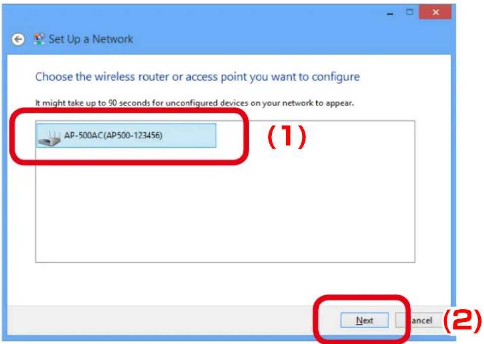
text_image
Set Up a Network Choose the wireless router or access point you want to configure It might take up to 90 seconds for unconfigured devices on your network to appear. AP-500AC(AP500-123456) (1) Next Cancel (2)
Note
- If two or more of AP-500AC are displayed, select the correct one by checking the host name on the right.
4. Enter the PIN code of AP-500AC to PIN: field and click Next.
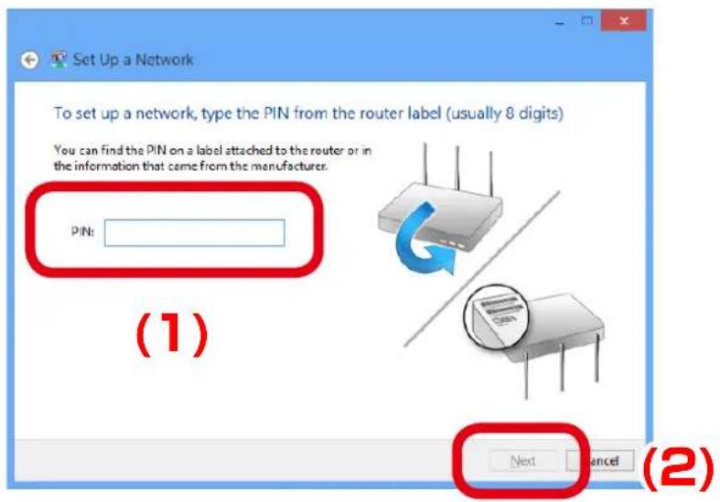
text_image
Set Up a Network To set up a network, type the PIN from the router label (usually 8 digits) You can find the PIN on a label attached to the router or in the information that came from the manufacturer. PIN: (1) Next Cancel (2)
- PIN code is a 8-digit number that can be found on the bottom label of AP-500AC.
5. Enter an SSID to Type your network name.
Click the down arrow button on the right of Change passphrase, security level and encryption type (advanced) to configure Security key, Security level, Encryption type and Connect automatically. When finished entering the settings, click Next.
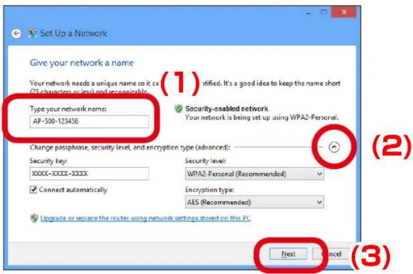
text_image
Set Up a Network Give your network a name Your network needs a unique name so it can (25 characters or less) and reconnable. Type your network name: AP-500-123456 Security-enabled network Your network is being set up using WPA2-Personal. Change passphrase, security level, and encryption type (advanced): Security key: XXXXX-XXXX-XXXX Security level: WPA2-Personal (Recommended) Connect automatically Encryption type: AES (Recommended) Upgrade or replace the router using network settings stored on this PC Next Cancel (1) (2) (3)6. Click Close.
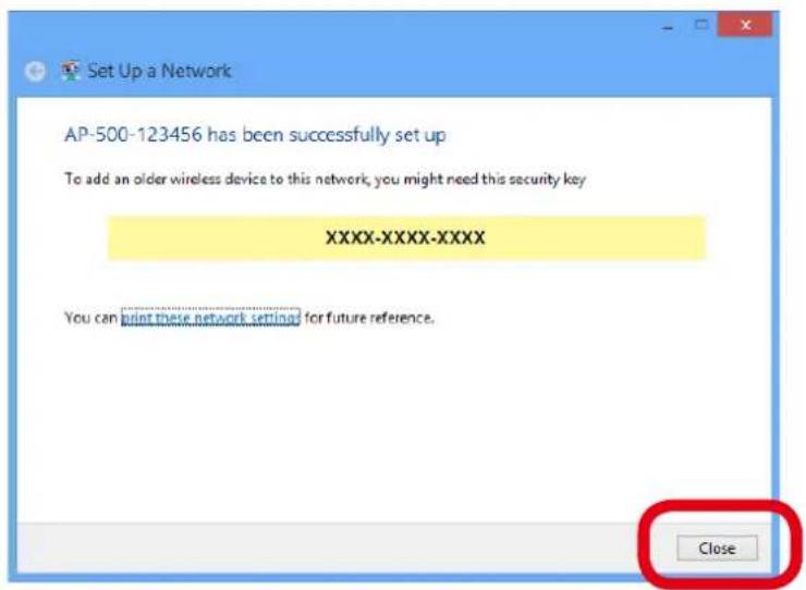
text_image
Set Up a Network AP-500-123456 has been successfully set up To add an older wireless device to this network, you might need this security key XXXX-XXXX-XXXX You can print these network settings for future reference. Close
- It is recommended to take notes of the security key.
Note
7. Change the network settings on the PC to access AP-500AC.
Example:
In case the default IP Address of AP-500AC is 10.0.17.34, change the network settings on your PC to the following:
- IP Address : 10.1.2.3
- Subnet Mask : 255.0.0.0

- Please be sure to set a unique address to your PC, that is not used for AP-500AC.
Note
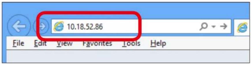
- Start a Web browser (Internet Explorer, Firefox, etc) on the PC you are using for the setup, enter the IP address of AP-500AC in the address bar and press the ENTER key.
text_image
10.18.52.86 File Edit View Favorites Tools Help
Note
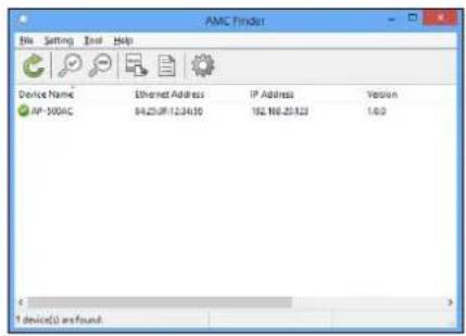
- By using the device search utility "AMC Finder" that can be downloaded from our homepage, it is possible to show all AP-500AC units as a list and access the Web page of each. For how to install and use AMC Finder, refer to 5-12. Product Search Utility.
text_image
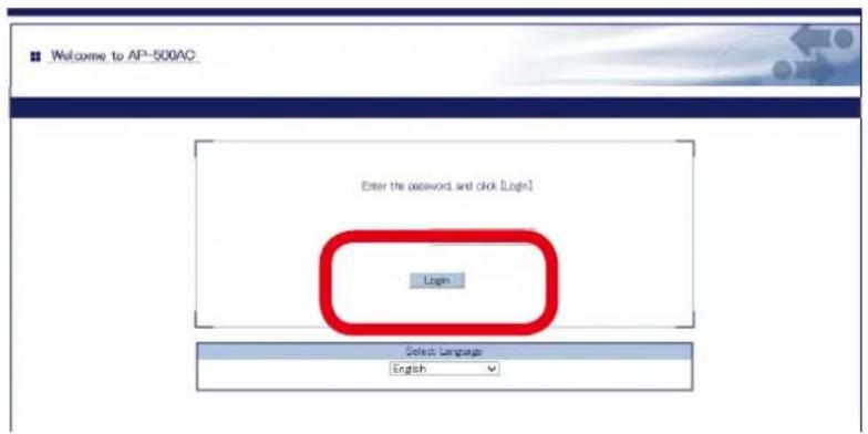
AMC Finder File Setting Tools Help Device Name Ethernet Address IP Address Institution AP-500AC 94.25.0912.34.00 192.NB.20.823 1:03 1 device(s) are found- The login menu window is displayed. Enter the password and click Login to login to the Web page.
text_image
Welcome to AP-500AC. Enter the password and click Login1 Login Select Language English
- No password is set by default. In such case, just click Login.
Note
Web page has been displayed. Go on to 3-3. Configuration at Web Page.
3-2. Displaying Web Page of AP-500AC (After Initial Configuration)
AP-500AC settings can be configured from its Web page.
After the initial configuration is finished, access the Web page of AP-500AC on your PC to change the settings.

- If the PC is blocked by MAC Address filter of AP-500AC, the Web page cannot be displayed. - By default, it is impossible to access Web page as the port filter setting denies HTTP access over a wireless LAN. To use this method, change the port filter setting in advance to allow HTTP access over a wireless LAN.
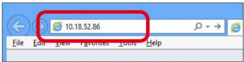
- Start a Web browser (Internet Explorer, Firefox, etc) on the PC you are using for the setup, enter the IP address of AP-500AC in the address bar and press the ENTER key.
text_image
10.18.52.86 File Edit View Favorites Tools Help
- By using the device search utility "AMC Finder" that can be downloaded from our homepage, it is possible to show all AP-500AC units as a list and access the Web page of each. For how to install and use AMC Finder, refer to 5-12. Product Search Utility.
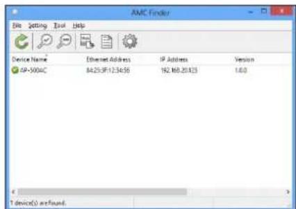
text_image
AMC Finder File Setting Tools Help Device Name Ethernet Address IP Address Version SP-500AC 84293F123456 192 MB28123 1.0.0 T device(s) are found.2. The login menu window is displayed.
Enter the password and click Login to login to the Web page.
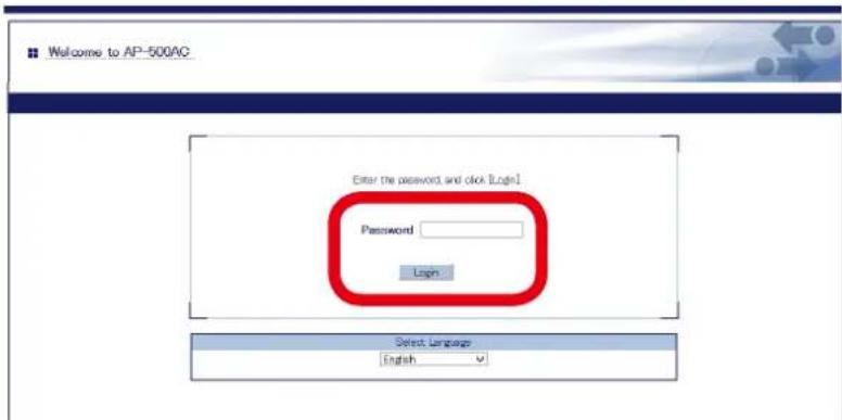
text_image
Welcome to AP-500AC Enter the password and click [Login] Password Login Select Language English
Note
- When no password is set, just click Login.
3-3. Configuration at Web Page
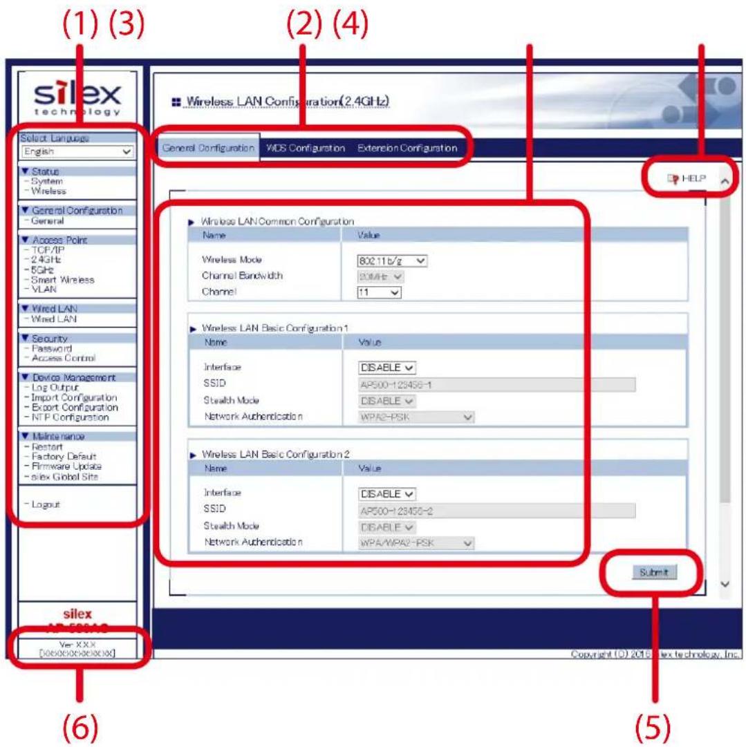
text_image
(1) (3) (2) (4) silex technology Select Languages English Status - System - Wireless General Configuration - General Access Point - TCP/IP - 2.4GHz - 6GHz - Smart Wireless - VLAN Wired LAN - Wired LAN Security - Password - Access Control Device Management - Log Output - Import Configuration - Export Configuration - NTP Configuration Maintenance - Restart - Factory Default - Firmware Update - silex Global Site - Logout silex WIREGAGE Ver XXX [000000000000] Wireless LAN Configuration(2.4GHz) General Configuration WIDS Configuration Extension Configuration HELP Wireless LAN Common Configuration Name Value Wireless Mode 802.11b/g Channel Bandwidth 90MFE Channel 11 Wireless LAN Basic Configuration1 Name Value Interface DISABLE SSID AP500-123456-1 Stealth Mode DISABLE Network Authentication WPA2-PSK Wireless LAN Basic Configuration2 Name Value Interface DISABLE SSID AP500-123456-2 Stealth Mode DISABLE Network Authentication WPA/WPA2-PSK Submit Copyright © 2015 Silex technology, Inc. (6) (5)(1) Menu
Changes the language (English/Japanese) and provides configuration menu.
(2) Tab
Changes the tabs of configuration.
(3) Configuration page
Provides each setting.
(4) Link to Help page
Opens the Help page that provides explanation on each setting.
(5) Submit button
Saves the settings you configured at each page.
(6) Firmware version / MAC Address
Shows the firmware version and MAC Address of AP-500AC.
| Category Page Description | ||
| Status | System Shows the system information. | |
| Wireless Shows information of the connected wireless client devices. | ||
| General Configuration | General Provides general configuration for TCP/IP and wireless LAN. | |
| Access Point | TCP/IP Provides the TCP/IP configuration. | |
| 2.4GHz | Provides the wireless LAN configuration (2.4GHz/5GHz).For details on WDS, refer to 5.4 WDS Feature. | |
| 5GHz | ||
| Smart Wireless Provides the settings for Smart Wireless Setup. | ||
| VLAN | Configures the VLAN settings. For details, refer to 5-5. VLAN Feature. | |
| Wired LAN | Wired LAN Configures the physical network type. | |
| Security Password | Configures the password to manage the AP-500AC. | |
| Access Control | Configures the access control setting.For details on MAC Address filter, refer to 5-6. MAC Address Filter. | |
| Device Management | Log Output Configures the log output settings. | |
| Import Configuration Configures AP-500AC using a configuration file. | ||
| Export Configuration | Saves the configuration of AP-500AC as a file. | |
| NTP Configuration | Sets the NTP server to retrieve time information from. | |
| Maintenance | Restart | Restarts AP-500AC. |
| Factory Default | Resets AP-500AC to factory default setting. | |
| Firmware Update | Updates the firmware version of AP-500AC. | |
| silex Global Site | Displays Silex Technology's homepage. | |

TIP
- Please be sure to set a password when you connect AP-500AC to a public network.
- Please be sure to use encryption when you connect AP-500AC to the wireless network.
- Wireless bands for IEEE 802.11b/g or IEEE 802.11b/g/n are often in use by other people because the number of devices supporting these standards is growing rapidly. If these wireless modes are used, you may run into issues with having enough communication bandwidth.
- When using AP-500AC outdoors, you must observe the radio regulations of each country. In some countries, the use of particular wireless bands (channels) outdoors is strictly prohibited.
-
When using W53 (52/56/60/64ch) or W56 (100/104/108/112/116/120/124/128/132/136/140ch) channels, please be careful of the restrictions addressed at 2. About AP-500AC - 2-6. Wireless Interference Information - DFS.
-
Click the menu and tabs and configure the settings on each page. When the configuration is finished, click Submit.
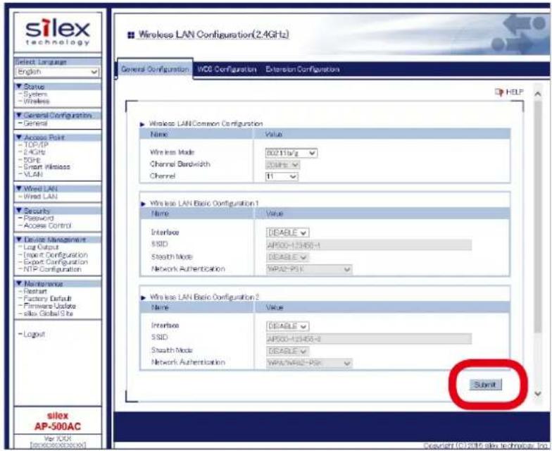
text_image
silex technology Select Language English Status - Systems - Wireless General Configuration - General Access Point - TCP/IP - 2.4GHz - 50Hz - Smart Wireless - VLAN Wired LAN - Wired LAN Security - Password - Access Control Device Management - Log Output - Export Configuration - Export Configuration - NTP Configuration Maintenance - Restart - Factory Default - Firmware Update - silox Global Bits - Logout silex AP-500AC Var IOSX [weizh@osex.com] Wireless LAN Configuration(2.4GHz) General Configuration WCG Configuration Extension Configuration Wireless LAN Common Configuration Name Value Wireless Mode 002116/s/g Channel Bandwidth 00896/s/g Channel 11 Wireless LAN Basic Configuration 1 Name Value Interface DEABLE SSID AP500-123456-1 Streath Mode DEABLE Network Authentication WPA2-PSK Wireless LAN Basic Configuration 2 Name Value Interface DEABLE SSID AP500-123456-2 Streath Mode DEABLE Network Authentication WPA2-WPA2-PSK Submit
- To enable the DHCP server feature, disable the DHCP client feature and assign a static IP Address to AP-500AC.
- MAC Address filter cannot be used on a wireless interface if Smart Wireless Setup is enabled on it. To use MAC Address filter, select the wireless interface that does not use MAC Address filter at Smart Wireless Setup page.

- Clicking Help on top right of the Web page will open the Help page.
- For details on each configuration item, refer to A-1. List of All Settings.
- In each page, click Submit button to save the settings you have configured. If other menu is clicked without clicking Submit button, the entered information will be cleared.
- Changes will take effect after AP-500AC is restarted.
2. The settings are saved and Restart button is displayed.
To continue configuration, click the menu you want to configure next. When necessary settings have been configured, click Restart.
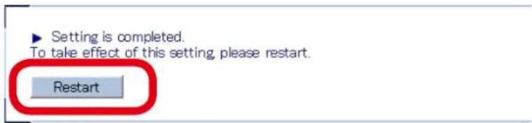
text_image
Setting is completed. To take effect of this setting, please restart. Restart
- AP-500AC can be restarted from Restart page of Maintenance.
3. After the Restart button is clicked, the progress bar is displayed. When the progress bar reaches the right end, the restart is completed. Close your Web browser.

text_image
Please wait for a while until the restart is complete.
- When restart is completed, ACTIVE LED turns Green on AP-500AC.
The configuration is completed.
To continue to install AP-500AC to a location of use, unplug the AC adaptor and network cable from AP-500AC according to instructions below.
Go on to 3-4. Installing AP-500AC then.
- Unplug the AC plug from the outlet and then AC adaptor from AP-500AC.
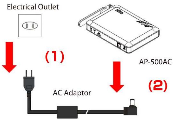
flowchart
graph TD
    A["Electrical Outlet"] -->|Red Arrow| B["AC Adaptor"]
    B --> C["AP-500AC"]
    C -->|Red Arrow| D["Ground"]
- Unplug the network cable from AP-500AC.
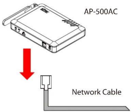
text_image
AP-500AC Network Cable3-4. Installing AP-500AC
Install AP-500AC to a location of use.
Adjust direction of the antenna according to how you have installed the unit.
Location of Installation
When placing the unit on a table
Place the unit on a table with good line of sight.
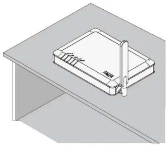
natural_image
Isometric line drawing of a rectangular device mounted on a flat base, with no visible text or symbols.
- Do not place the unit on tilted or unstable surfaces.
When hanging the unit on a wall
Hang the unit on higher position of the wall to make sure of a good line of sight.
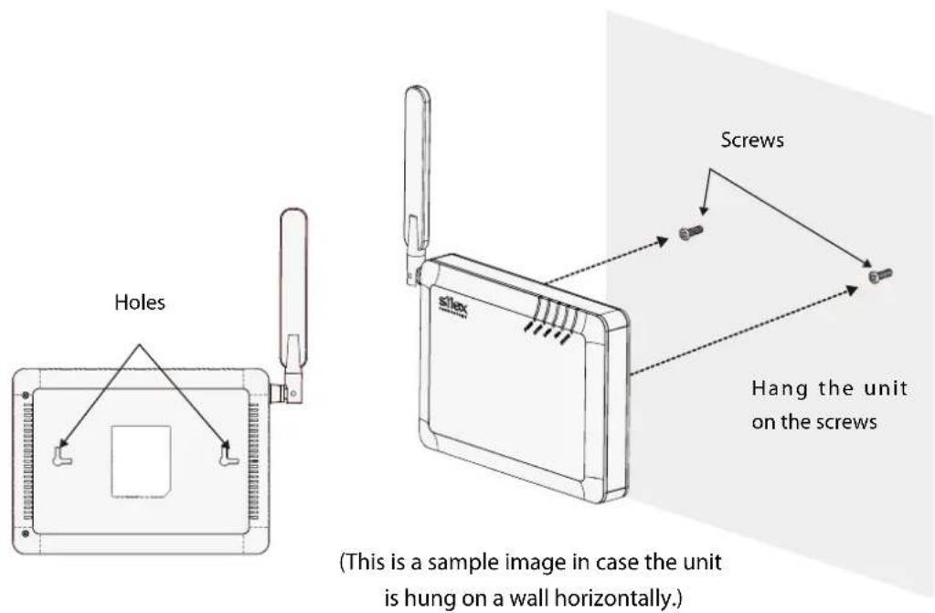
text_image
Holes Screws Hang the unit on the screws (This is a sample image in case the unit is hung on a wall horizontally.)
- The screws do not come with the unit. They need to be purchased separately.
- The unit may drop if it is not firmly hung on a wall. After hanging the unit on the screws, slightly move the unit horizontally and vertically to make sure it is fastened.
Change the Antenna Direction
When placing the unit on its bottom
Stand the antenna upright
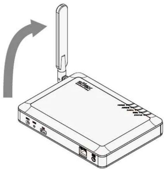
natural_image
Line drawing of a wireless router with a cable outlet and indicator lights, showing no text or symbols on the device itself.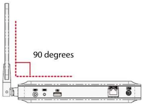
text_image
90 degrees
TIP
- Do not push the antenna to a wrong direction.
- When you turn the antenna, please be sensitive to the limit of its stopper.
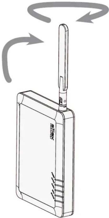
When hanging the unit horizontally on a wall
(2) Turn the antenna
(1) Stand the antenna upright
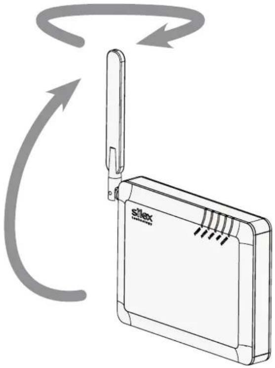
natural_image
Diagram of a Siemens Slex device with directional arrows indicating rotation or signal flow (no text or symbols on the device itself)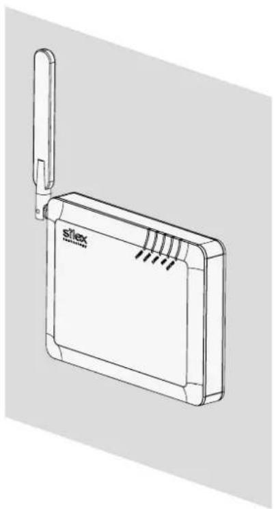
natural_image
Line drawing of a Siemens Max 3.0 network device (no text or symbols on the device body)(3) Hang the unit on a wall

- Do not push the antenna to a wrong direction.
- When you turn the antenna, please be sensitive to the limit of its stopper.
When hanging the unit vertically on a wall
(1) Stand the antenna upright
(2) Turn the antenna
natural_image
Line drawing of a wireless router device with a cable and antenna, showing signal flow arrows (no text or symbols)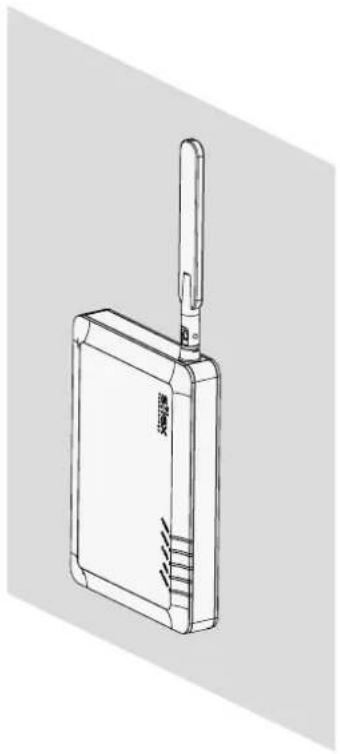
natural_image
Line drawing of a wireless device with a USB port and cable (no text or symbols)(3) Hang the unit on a wall

- Do not push the antenna to a wrong direction.
- When you turn the antenna, please be sensitive to the limit of its stopper.
Connect AP-500AC to a network
1. Connect AP-500AC and Ethernet Hub via a network cable.
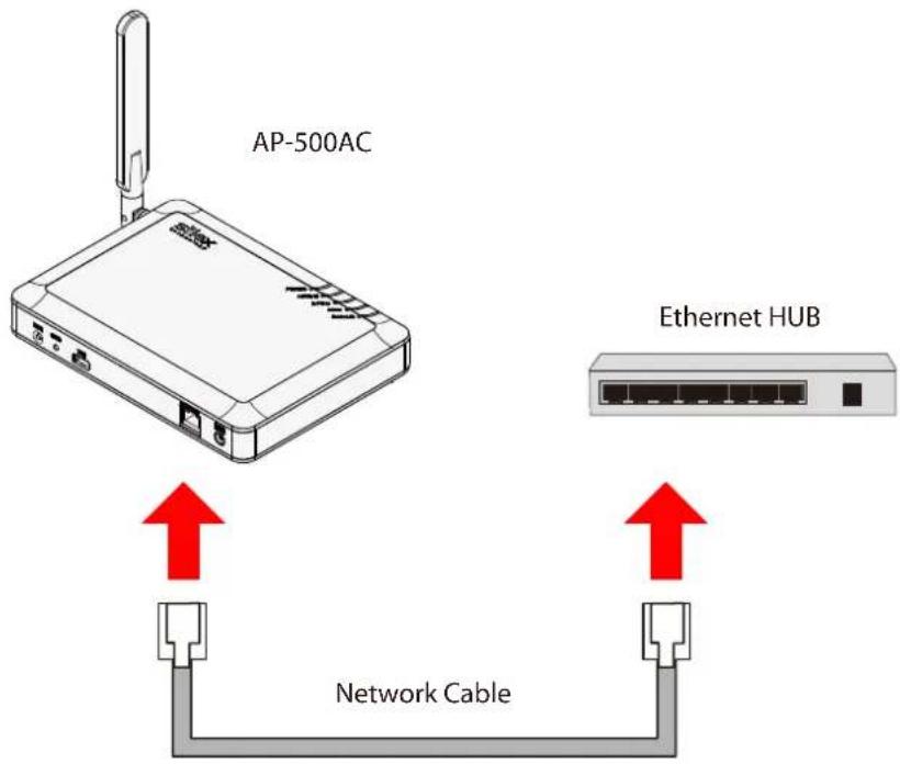
text_image
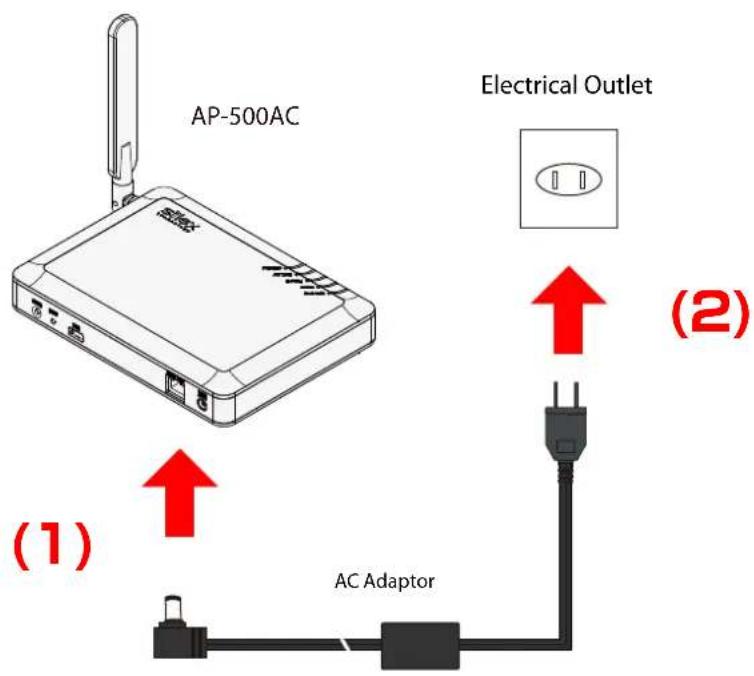
AP-500AC Ethernet HUB Network Cable2. Connect the AC adapter to AP-500AC and AC plug to a power outlet.
text_image
AP-500AC Electrical Outlet (1) AC Adaptor (2)
- When receiving power over Ethernet (PoE), the AC adaptor does not need to be connected. Make sure that the PoE supported HUB or PoE power supply unit is used then.
4. Connecting Wireless Device
This chapter explains how to connect your PC and wireless devices to AP-500AC.
4-1. Connecting PC
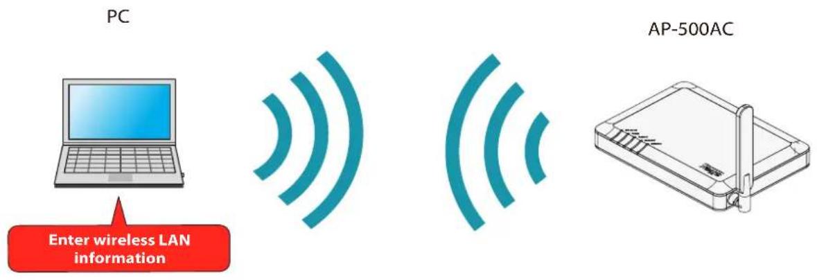
Following explains how to connect your PC to AP-500AC as a wireless client device.
text_image
PC Enter wireless LAN information AP-500AC
- Before connecting your PC, you need to know SSID and Security Key configured on AP-500AC (Pre-Shared Key or WEP Key).
- In the following instructions, the screenshots captured from Windows 8 will be used. When an operating system other than Windows 8 is used, the procedure may be different.
- Move your cursor to top-right or bottom right corners (when a touch-panel device is used, swipe your finger from the right edge) and click Settings from the charm bar.
text_image
Settings- Click the icon below to show the wireless connection window.

text_image
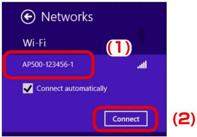
Available- Select the SSID configured on AP-500AC from a list and click Connect.
text_image
Networks Wi-Fi (1) AP500-123456-1 Connect automatically Connect (2)
- When Connect automatically is checked, the PC will automatically be connected when it is restarted next time.
- Enter the security key of AP-500AC for Enter the network security key and click Next.
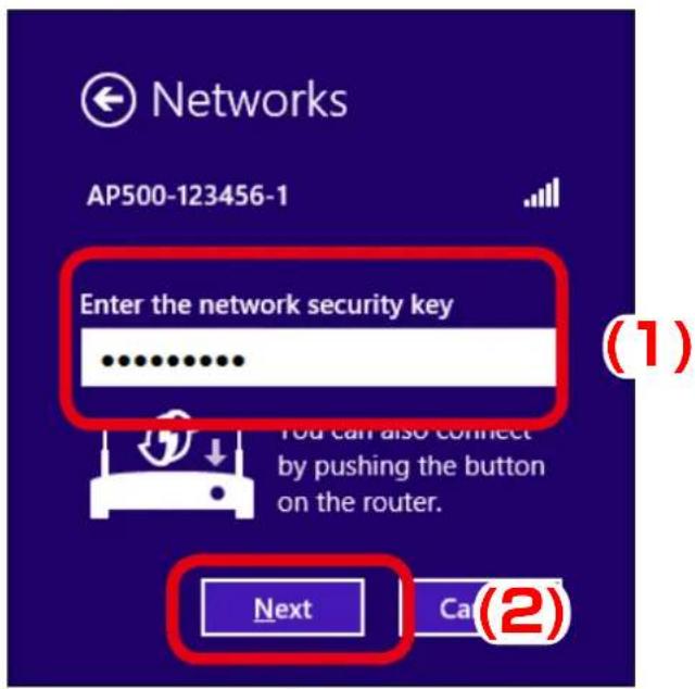
text_image
Networks AP500-123456-1 Enter the network security key You can also connect by pushing the button on the router. Next Call (2)5. Click No, don't turn on sharing or connect to devices.
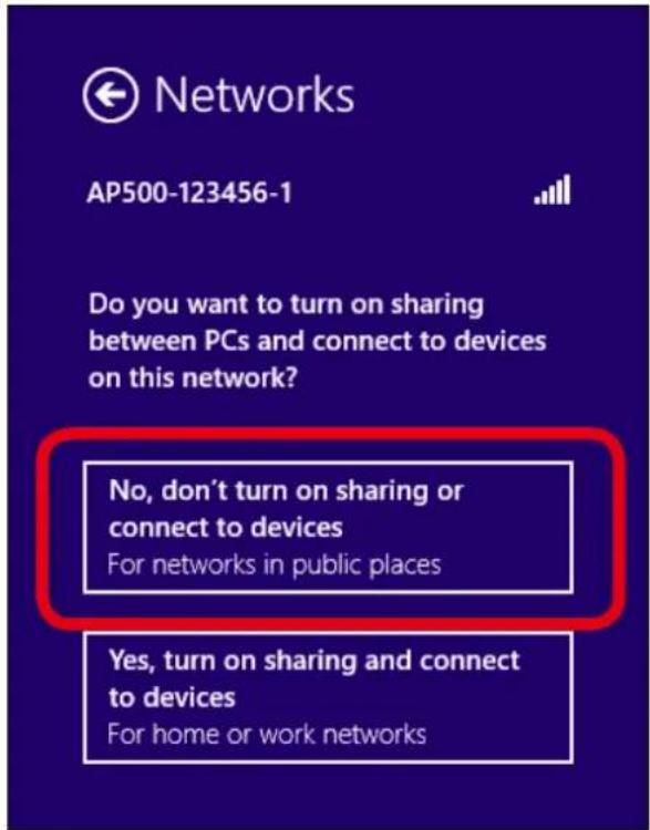
text_image
Networks AP500-123456-1 Do you want to turn on sharing between PCs and connect to devices on this network? No, don't turn on sharing or connect to devices For networks in public places Yes, turn on sharing and connect to devices For home or work networksPC has been connected to AP-500AC.
4-2. Connecting Wireless Device Using Smart Wireless Setup Switch
Following explains how to connect wireless client devices to AP-500AC using the Smart Wireless Setup switch (Push Switch SW1).
To configure using the Smart Wireless Setup, the wireless client device needs to support WPS (Wi-Fi Protected Setup). When you are not sure if the wireless client device supports WPS or not, see the operating manual that came with the device or contact the manufacturer.
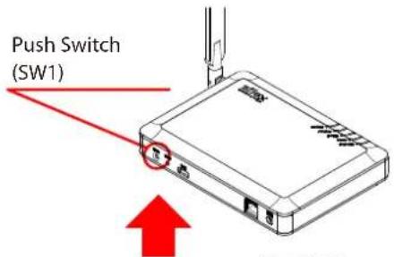
text_image
Push Switch (SW1)(1)

AP-500AC
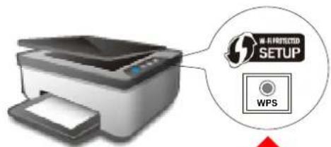
text_image
W-B-PROTECTED SETUP WPSWireless Device (MFP, etc.)

natural_image
Illustration of a hand pointing upward with a red upward arrow above it (no text or symbols)
TIP
- During this configuration, please place your wireless device closer to AP-500AC so that they can communicate better.

Note
- By default, wireless interface 1 (2.4GHz) is set as wireless interface that can use Smart Wireless Setup.
- When the stealth mode is enabled on AP-500AC, wireless connection method using Smart Wireless Setup cannot be used.
- Press and hold the push switch (SW1). Release it when STATUS LED start blinking in Green.
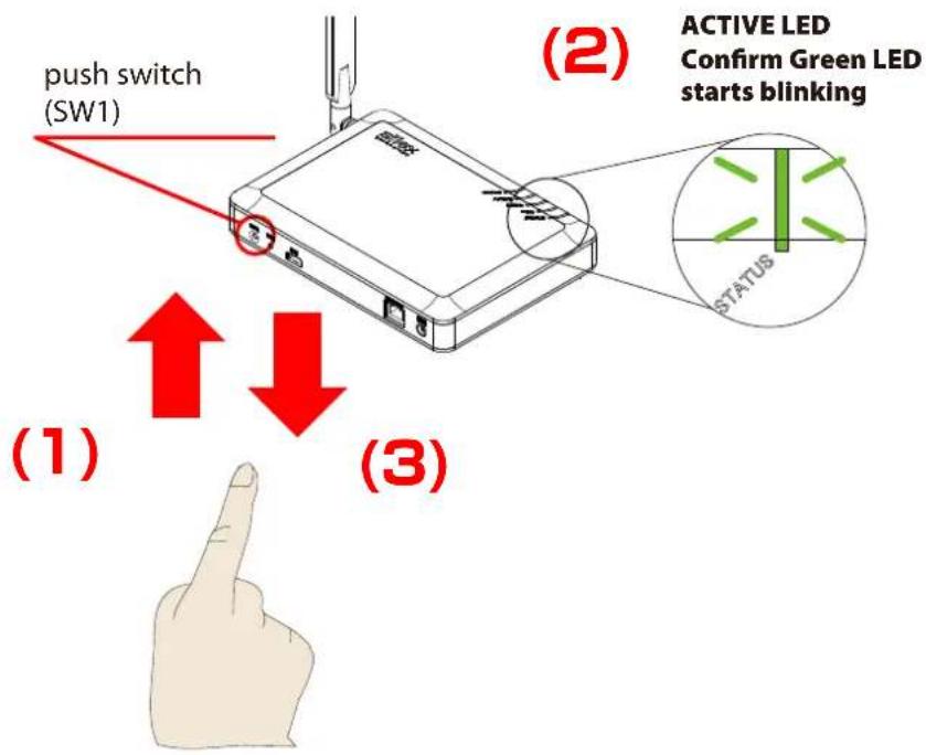
text_image
push switch (SW1) (1) (ACTIVE LED Confirm Green LED starts blinking STATUS (2) (3)- Press the wireless setup switch also on your wireless device.
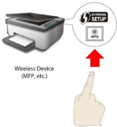
text_image
Wireless Device (MFP, etc.) WPS WIRELESS SETUP
- Please use only one wireless device. Even if two or more devices are waiting for wireless connections, AP-500AC can configure only one device which has replied first.

- The name, position and shape of the wireless setup switch(WPS button) will differ depending on your wireless device. For details, refer to the operation manual that came with your wireless device.
- AP-500AC will start to communicate with your wireless device and configure the same wireless settings. The STATUS LED will turn to Green when the configuration is completed.
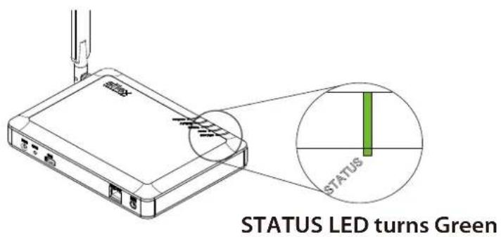
text_image
STATUS LED turns Green
Note
- If STATUS LED turns to Red, the configuration would have failed. Read the notes on this configuration and try again.
- STATUS LED (Green/Red) will turn off in 3 mins.
The wireless client device has been connected to AP-500AC.
4-3. Connecting Wireless Device by Push Button Method of Web Page
Following explains how to connect wireless client devices to AP-500AC using the Push Button method of Web page.
To configure using the Smart Wireless Setup, the wireless client device needs to support WPS (Wi-Fi Protected Setup). When you are not sure if the wireless client device supports WPS or not, see the operating manual that came with the device or contact the manufacturer.
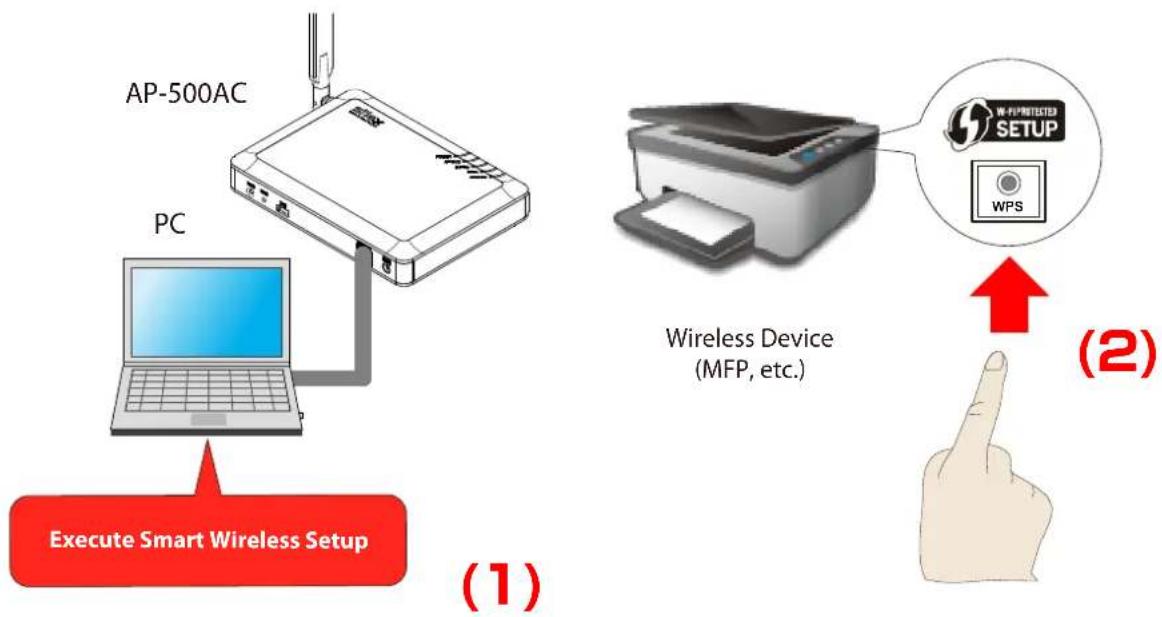
flowchart
graph TD
    A["AP-500AC"] --> B["PC"]
    B --> C["Execute Smart Wireless Setup"]
    D["Wireless Device (MFP, etc.)"] --> E["WIP-PROTECTED SETUP"]
    E --> F["WPS"]
    G["Hand Icon"] --> H["↑"]
    style A fill:#f9f,stroke:#333
    style D fill:#ccf,stroke:#333
    style G fill:#cfc,stroke:#333

- During this configuration, please place your wireless device closer to AP-500AC so that they can communicate better.

- By default, wireless interface 1 (2.4GHz) is set as wireless interface that can use Smart Wireless Setup.
- When the stealth mode is enabled on AP-500AC, wireless connection method using Smart Wireless Setup cannot be used.
- Log in to the Web page of AP-500AC using your Web browser.

text_image
Welcome to AP-500AC Enter the password and click [Login] Password Login Select Language English
Note
- For how to display the Web page after the initial configuration, refer to 3-2. Displaying Web Page of AP-500AC (After Initial Configuration).
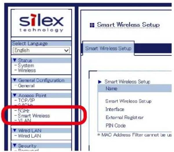
- From the left menu on the Web page, click Smart Wireless.
text_image
silex technology Select Language English Status - System - Wireless General Configuration - General Access Point - TCP/IP - 5GHz - Smart Wireless - VLAN Wired LAN - Wired LAN Security Smart Wireless Setup Smart Wireless Setup Name Smart Wireless Setup Interface External Register PIN Code * MAC Address Filter cannot be us3. Click Execute at Push Button under Smart Wireless Setup Execute.

text_image
Smart Wireless Setup Execute Name Push Button Execute PIN Code Register
- The STATUS LED blinks Green when the Smart Wireless Setup is in process.
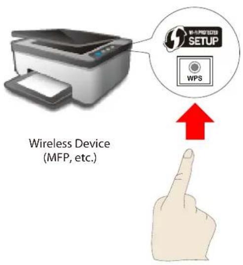
4. Press the wireless setup switch on your wireless device.
text_image
Wireless Device (MFP, etc.) WPS W-P PROTECTER SETUP
- Please use only one wireless device. Even if two or more devices are waiting for wireless connections, AP-500AC can configure only one device which has replied first.

- The name, position and shape of the wireless setup switch(WPS button) will differ depending on your wireless device. For details, refer to the operation manual that came with your wireless device.
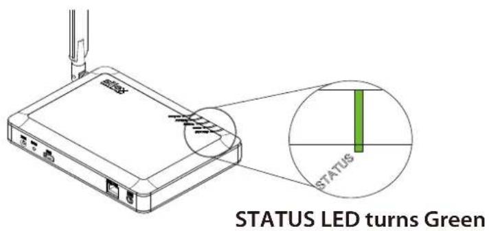
- AP-500AC will start to communicate with your wireless device and configure the same wireless settings. The STATUS LED will turn to Green when the configuration is completed.
text_image
STATUS LED turns Green
Note
- If STATUS LED turns to Red, the configuration would have failed. Read the notes on this configuration and try again.
- STATUS LED (Green/Red) will turn off in 3 mins.
The wireless client device has been connected to AP-500AC.
4-4. Connecting Wireless Device by Entering PIN Code on Web Page
Following explains how to connect wireless client devices to AP-500AC using the PIN Code method of Web page.
To configure using the Smart Wireless Setup, the wireless client device needs to support WPS (Wi-Fi Protected Setup). When you are not sure if the wireless client device supports WPS or not, see the operating manual that came with the device or contact the manufacturer.
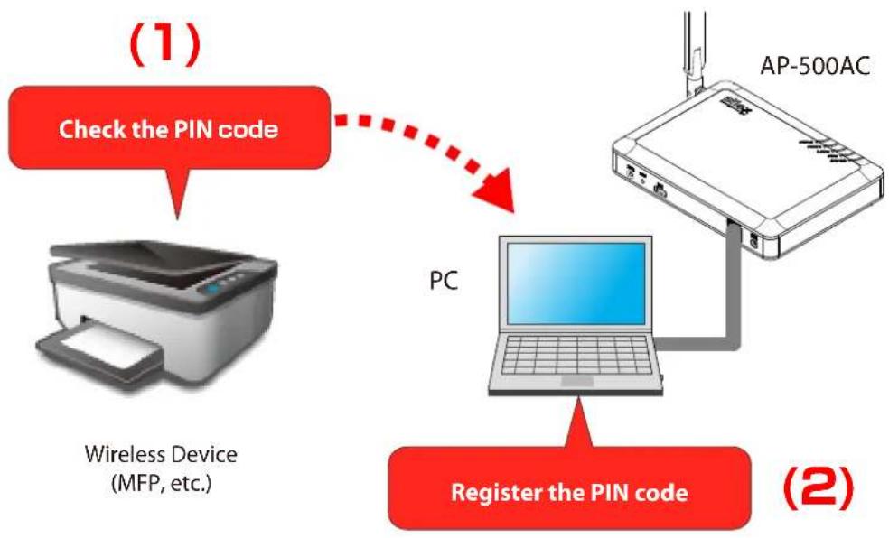
flowchart
graph TD
    A["Check the PIN code"] --> B["PC"]
    B --> C["Register the PIN code"]
    D["Wireless Device (MFP, etc.)"] --> A
    E["AP-500AC"] --> B

- During this configuration, please place your wireless device closer to AP-500AC so that they can communicate better.

- By default, wireless interface 1 (2.4GHz) is set as wireless interface that can use Smart Wireless Setup. - When the stealth mode is enabled on AP-500AC, wireless connection method using Smart Wireless Setup cannot be used.
- Check the PIN code of wireless device to connect to AP-500AC.
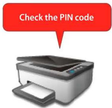
text_image
Check the PIN codeWireless Device (MFP, etc.)

- Do not enter the PIN code that is described on the bottom label of AP-500AC.

Note
- For how to know the PIN code, see the operating manual of the wireless device.
- Log in to the Web page of AP-500AC using your Web browser.
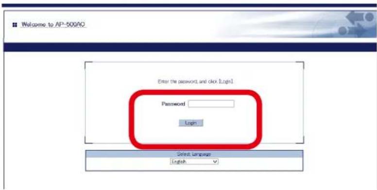
text_image
Welcome to AP-500AC Enter the password and click [Login] Password Login Select Language English
- For how to display the Web page after the initial configuration, refer to 3-2. Displaying Web Page of AP-500AC (After Initial Configuration).
3. From the left menu on the Web page, click Smart Wireless.
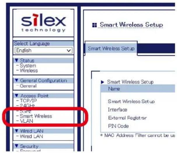
text_image
silex technology Select Language English Status - System - Wireless General Configuration - General Access Point - TCP/IP - 24GHz - 6.6Hz - Smart Wireless - VLAN Wired LAN - Wired LAN Security Smart Wireless Setup Name Smart Wireless Setup Interface External Registrar PIN Code * MAC Address Filter cannot be us4. Enter the PIN code of wireless device at PIN Code under Smart Wireless Setup Execute and click Register.

text_image
Smart Wireless Setup Execute Name Push Button PIN Code Execute Register
- The STATUS LED blinks Green when the Smart Wireless Setup is in process.
- AP-500AC will start to communicate with your wireless device and configure the same wireless settings. The STATUS LED will turn to Green when the configuration is completed.
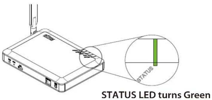
text_image
STATUS LED turns Green
- If STATUS LED turns to Red, the configuration would have failed. Read the notes on this configuration and try again.
- STATUS LED (Green/Red) will turn off in 3 mins.
- If STATUS LED blinks in Red rapidly for 1 sec, the configuration would have failed. Check the PIN code setting and try again.
The wireless client device has been connected to AP-500AC.
5. Other Features
This chapter explains the other features of AP-500AC.
5-1. System Status of Connected Wireless Device
In addition to TCP/IP and wireless setting information of AP-500AC, the MAC Address, wireless signal strength, etc. of the connected station devices can be seen on the Web page.
- Log in to the Web page of AP-500AC using your Web browser.
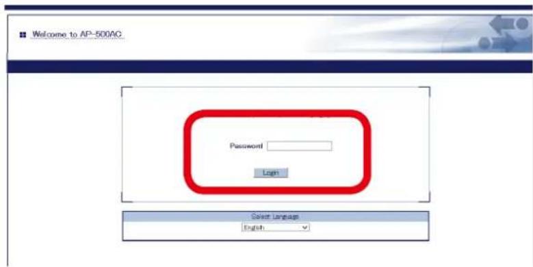
text_image
Welcome to AP-500AC Password Login Select Language English
Note
- For how to display the Web page after the initial configuration, refer to 3-2. Displaying Web Page of AP-500AC (After Initial Configuration).
- The system status page will be displayed after you have logged into the Web page. From the left menu in the Web page, click System. This page shows the general settings such as TCP/IP information, Wireless LAN settings, etc.
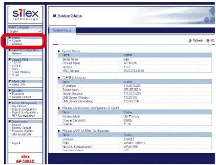
text_image
silex technology Solid Language English Status - System - Wireless - Semi-Configuration - General Access Point - TCP/IP - 2.4GHz - EGHz - Smart Windows - VLAN - Wind LAN - Wind LAN Security - Password - Access Control Device Management - Log Output - Import Configuration - Export Configuration - NIP Configuration Maintenance - Report - Factory Default - Private Update - Solar Global Site - Loginui silex AP-500AC System Status System Status Name Status Serial Name silk Product Name AP-500AC Version 1:00 MAC Address 84/253/12.34156 TCP/IP Information Name Status IP Address 17225 72.253 Subnet Mask 255.255.252.0 Default Gateway 17225 75.230 DNS Server (Primary) 17225.1.55 DNS Server (Secondary) 172250.0100 Wireless LAN Common Configuration (S AGHS) Name Status Wireless Mode 93/11n/b/g Channel Bandwidth 20MHz Channel 11 oh Wireless LAN1 (S AGHS) Configuration Name Status Interface ENABLE SSID AP900-123450-1 Network Authentication WPAS-RSK Complete Mode 477If you click Wireless, the status page for wireless station devices is displayed. In this page, you can check the MAC Address, RSSI (wireless signal strength) and IP Address for the connected wireless station devices.

text_image
Silex Technology Select Language English System - Wireless LAN0.5 Active Port - TCP/IP - 2.4GPs - BCH - Smart Wireless - VLAN Wind LAN - Wind LAN1 Security - Password - Access Control Device Management - Log Output - Export Configuration - Export Configuration - NFP Configuration Maintenance - Report - Policy Default - Firmware Update - Sale Global Site - Layout silex AP-500AC Access Point Wireless Status Status Refresh HELP ZAGP6 - Wireless LAN1 MVC Address 04:25:3F 11:22:5E Wireless Signal Strength(K/Em) 1-1T1 IP Address ZAGP6 - Wireless LAN2 MVC Address —— Wireless Signal Strength(K/Em) —— IP Address ZAGP6 - Wireless LAN3 MVC Address 04:25:3F 11:22:5E Wireless Signal Strength(K/Em) 1-1T1 IP Address ZAGP6 - Wireless LAN4 MVC Address —— Wireless Signal Strength(K/Em) —— IP Address5-2. DHCP Server Feature
If DHCP Server Function is used, an IP address can automatically be assigned to PCs or network devices.

- To assign an IP address to your PC automatically using the DHCP server feature of AP-500AC, your PC must be set to Obtain an IP address automatically.
- Log in to the Web page of AP-500AC using your Web browser.
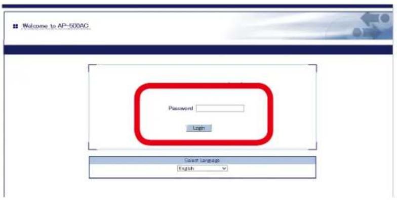
text_image
Welcome to AP-500AC Password Login Select Language English
- For how to display the Web page after the initial configuration, refer to 3-2. Displaying Web Page of AP-500AC (After Initial Configuration).
- From the left menu in the Web page, click TCP/IP or General.
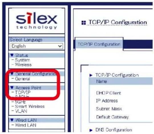
text_image
silex technology Select Language English Status - System - Wireless General Configuration - General Access Point - TCP/IP - 30GHz - 5GHz - Smart Wireless - VLAN Wired LAN - Wired LAN TCP/IP Configuration TCP/IP Configuration Name DHCP Client IP Address Subnet Mask Default Gateway DNS Configuration3. Select DISABLE for DHCP Client and configure a static IP Address.
If ENABLE is selected at DHCP Server Function, the following settings will become available. After entering the settings, click Submit on the bottom right of Web page.
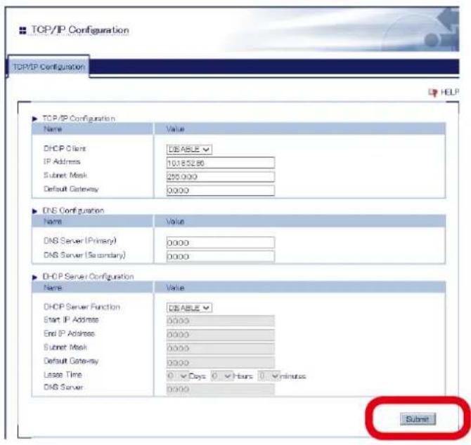
text_image
TOP/IP Configuration TCP/IP Configuration HELP TOP/IP Configuration Name Value DHCP Client DEABLE IP Address 10185286 Submit Mask 250.000 Default Gateway 0.000 DNS Configuration Name Value DNS Server (Primary) 0.000 DNS Server (Secondary) 0.000 DHCP Server Configuration Name Value DHCP Server Function DEABLE Start IP Address 0.000 End IP Address 0.000 Submit Mask 0.000 Default Gateway 0.000 Laser Time 0 Days 0 Hours 0 minutes DNS Server 0.000 SubmitDHCP Server Configuration
| Name Description | |
| DHCP Server Function Enable/Disable the DHCP Server. | |
| Start IP Address Set the start IP address. | |
| End IP Address Set the end IP address. | |
| Subnet Mask Set the subnet mask for IP address range.If 0.0.0.0 is set, the subnet mask appropriate for the Start IP Address will automatically be used. | |
| Default Gateway Set the gateway address. This is disabled if 0.0.0.0 (default value) is set. | |
| Lease Time Set the lease time (Days/Hours/Minutes).When the setting is "0Days 0Hours 0Minutes", assigned lease time to client is 10days. | |
| DNS Server Set the DNS Server address. | |

- To use the DHCP server feature, disable the DHCP client feature and assign a static IP Address to AP-500AC.
4. When finished, click Restart.
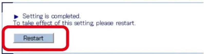
text_image
Setting is completed. To take effect of this setting, please restart. Restart
Note
- If you continue to configure the other settings, you do not have to restart. Please restart when you completed all other settings.
- The DHCP Server setting will not take effect unless you restart AP-500AC.
5. After the Restart button is clicked, the progress bar is displayed. When the progress bar reaches the right end, the restart is completed.

text_image
Please wait for a while until the restart is complete.5-3. IEEE802.1X Authentication
AP-500AC supports the IEEE802.1X authentication.
To use the IEEE802.1X authentication, a RADIUS server is needed.
Network Configuration
Connect the AP-500AC to a network as below when you use the IEEE802.1X authentication.
IP Address of RADIUS server and port number of EAPOL can be set.
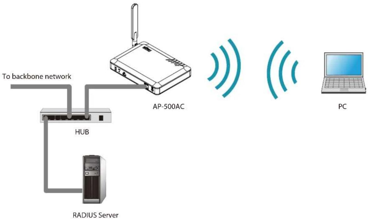
flowchart
graph TD
    A["AP-500AC"] -->|To backbone network| B["HUB"]
    B --> C["RADIUS Server"]
    C --> D["PC"]
IEEE802.1X Authentication
AP-500AC supports the following IEEE802.1X authentication methods.
| IEEE802.1X Authentication mode |
| EAP-TLS |
| EAP-TTLS |
| PEAP |

Note
- EAP-LEAP and EAP-FAST are not supported.
IEEE802.1X Authentication Settings
- Log in to the Web page of AP-500AC using your Web browser.
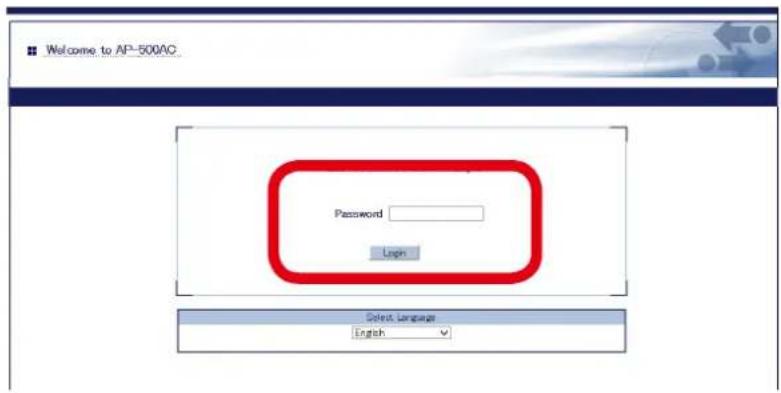
text_image
Welcome to AP-500AC Password Login Select Language English
Note
- For how to display the Web page after the initial configuration, refer to 3-2. Displaying Web Page of AP-500AC (After Initial Configuration).
- In the Web page, click the band (2.4GHz/5GHz) to use 802.1X authentication from the menu.
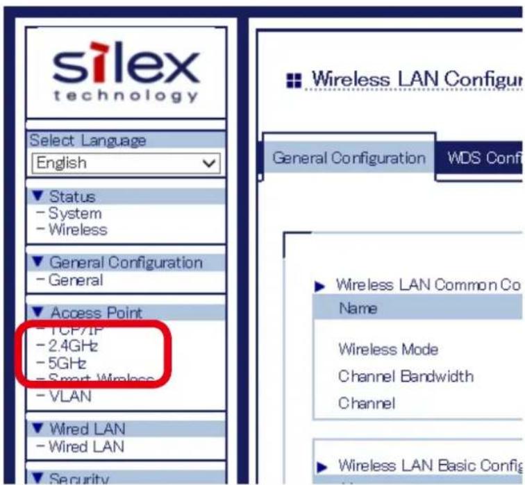
text_image
silex technology Select Language English Status - System - Wireless General Configuration - General Access Point - TCP/IP - 2.4GHz - 5GHz - Smart Wireless - VLAN Wired LAN - Wired LAN Security Wireless LAN Configur General Configuration WDS Conf ► Wireless LAN Common Co Name Wireless Mode Channel Bandwidth Channel ► Wireless LAN Basic Configur- Configure the settings for wireless interface to use 802.1X authentication and click Submit at bottom right of the page.
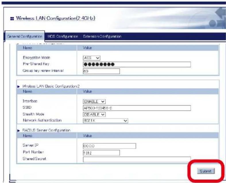
text_image
Wireless LAN Configuration(2.4GHz) General Configuration WCS Configuration ExtensionConfiguration Name Value Encryption Mode ABS Pre-Shared Key Group key renew interval 60 ► Wireless LAN Basic Configuration2 Name Value Interface ENABLE SSID AF500-123456-2 Stealth Mode DISABLE Network Authentication 8021X ► RADIUS Server Configuration Name Value Server IP 00.00 Port Number 1812 Shared Secret SubmitNetwork Authentication
| Name Description | |
| 802.1X Uses the 802.1X user authentication. For encryption mode, WEP can be used. | |
| WPA-Enterprise Uses the 802.1X user authentication. For encryption mode, TKIP/AES/AUTO can be used. | |
| WPA2-Enterprise Uses the 802.1X user authentication. For encryption mode, AES/AUTO can be used. | |
| WPA/WPA2-Enterprise Uses the 802.1X user authentication. For encryption mode, AES/AUTO can be used. | |
RADIUS Server Configuration
| Name Description | |
| Server IP Set the IP Address | s of RADIUS server. |
| This can be set only when the network authentication is 802.1X, WPA-Enterprise, WPA2-Enterprise or WPA/WPA2-Enterprise. | |
| Port Number Set the port | number used to communicate with RADIUS server. |
| Shared Secret Set the secret key used to communicate with RADIUS server. | |

Note
- For details on each configuration item, refer to A. Appendix - A-1. List of All Settings.
- For 802.11n/802.11ac, Shared / 802.1X authentication and WEP / TKIP encryption cannot be used.
4. When finished, click Restart.
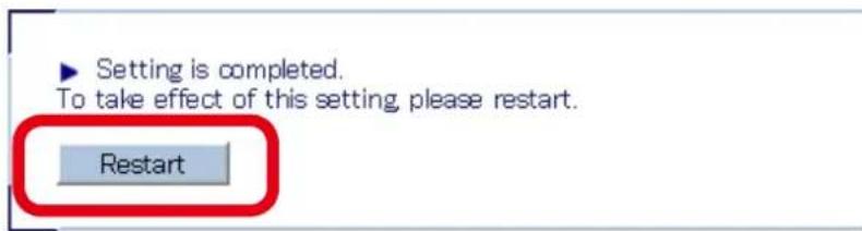
text_image
Setting is completed. To take effect of this setting, please restart. Restart
- If you continue to configure the other settings, you do not have to restart. Please restart when you completed all other settings.
- 802.1X authentication setting will not take effect unless you restart AP-500AC.
5. After the Restart button is clicked, the progress bar is displayed. When the progress bar reaches the right end, the restart is completed.

text_image
Please wait for a while until the restart is complete.5-4. WDS Feature
If this mode is used, two or more AP-500AC Access Points can communicate each other. By linking several Access Points wirelessly, wireless distance can be expanded as well as wireless dead spots can be eliminated. The connection and configuration methods to use WDS are explained.
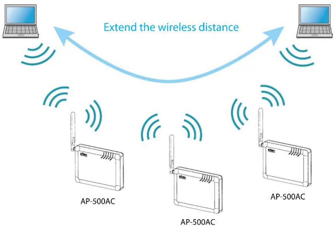
flowchart
graph TD
    A[" Laptop"] -->|Extend the wireless distance| B[" Laptop"]
    B --> C[" AP-500AC "]
    C --> D[" AP-500AC "]
    D --> E[" AP-500AC "]
    E --> F[" AP-500AC "]

- Please check that all AP-500AC Access Points are running on the same version of firmware.
- In the following instructions, the screenshots captured from Windows 8 will be used. Display may vary depending on your environment and Web browser.
- WDS is guaranteed only for Silex brand products that support WDS.
WDS Connection
The WDS(Wireless Distribution System) is composed of one Root AP (running as a host device) and plural Repeater APs (running as client devices).

flowchart
graph LR
    A[" "] --> B["Repeater"]
    B --> C["RepeaterRepeaterRoot AP"]
    C --> D[" "]
    style B stroke:#000,stroke-width:2px
    style C stroke:#000,stroke-width:2px
    style D stroke:#000,stroke-width:2px
    classDef blue stroke:#000,stroke-width:2px;
    class B,C blue;
When connecting Access Points, use the first AP as Root AP and the second or later APs as Repeater APs. As shown in below image, connect APs starting from the Root AP.
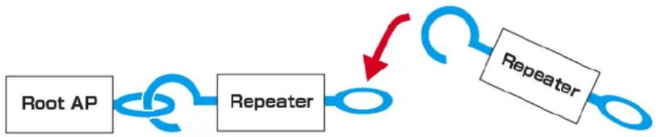
flowchart
graph LR
    A["Root AP"] --> B["Repeater"]
    B --> C["Repeater"]
    C --> A

- For Root AP and Repeater APs to connect in WDS mode, configure the same wireless settings.
Following settings must be the same:
- Wireless channel
- SSID
- Network authentication
- Encryption
- When using WDS, the following features cannot be used.
- 802.1X, WPA-Enterprise, WPA2-Enterprise, WPA/WPA2-Enterprise (of network authentication)
- AUTO (of channel setting) and DFS band channels (W53(52/56/60/64ch), W56(100/104/108/112/116/120/124/128/132/136/140ch))
-
Privacy Separator
-
When numbers of AP-500AC Access Points are connected in WDS, wireless communication speed may slow down.
- We do not guarantee the WDS connection if wireless devices other than AP-500AC are used.

- Only one Repeater AP can be connected for each 2.4GHz and 5GHz in WDS mode. Please do not allow the setting that connects two or more Repeater APs to Root AP or Repeater AP using the same band. We do not guarantee a successful connection between two or more Repeater APs as shown blow.
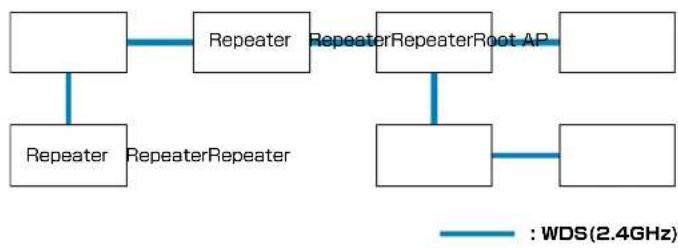
flowchart
graph LR
    A[" "] --> B["Repeater"]
    C["Repeater"] --> A
    B --> D["RepeaterRepeater"]
    D --> E["RepeaterRepeaterRoot AP"]
    E --> F[" "]
    E --> G[" "]
    G --> H[" "]
    style A fill:#fff,stroke:#000
    style C fill:#fff,stroke:#000
    style B fill:#fff,stroke:#000
    style E fill:#fff,stroke:#000
    style F fill:#fff,stroke:#000
    style G fill:#fff,stroke:#000
    style H fill:#fff,stroke:#000
- When WDS is used for both 2.4GHz and 5GHz bands simultaneously, please do not allow a link between the bands. It may cause a loop communication error.
Example of connection for WDS using both 2.4GHz/5GHz bands:
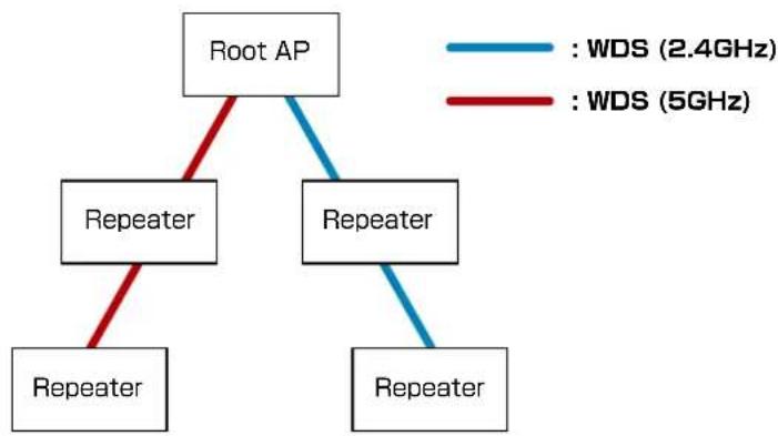
flowchart
graph TD
    A["Root AP"] --> B["Repeater"]
    A --> C["Repeater"]
    B --> D["Repeater"]
    C --> E["Repeater"]
    style A fill:#f9f,stroke:#333
    style B fill:#ccf,stroke:#333
    style C fill:#ccf,stroke:#333
    style D fill:#cfc,stroke:#333
    style E fill:#cfc,stroke:#333
    note1["WDS (2.4GHz)"]
    note2["WDS (5GHz)"]
Example of bad connection (loop error) for WDS:
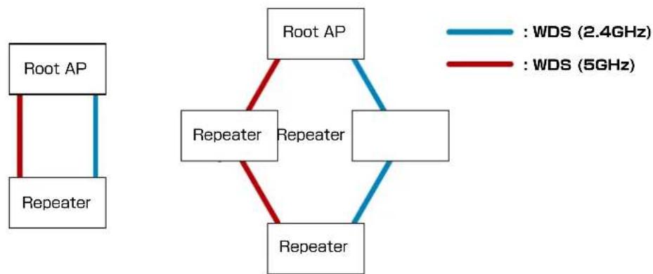
flowchart
graph TD
    A["Root AP"] --> B["Repeater"]
    C["Root AP"] --> D["Repeater"]
    E["Root AP"] --> F["Repeater"]
    G["Root AP"] --> H["Repeater"]
    I["Root AP"] --> J["Repeater"]
    K["Root AP"] --> L["Repeater"]
    M["Root AP"] --> N["Repeater"]
    O["Root AP"] --> P["Repeater"]
    Q["Root AP"] --> R["Repeater"]
    S["Root AP"] --> T["Repeater"]
    U["WDS (2.4GHz)"] --> V["Blue"]
    W["WDS (2.4GHz)"] --> X["Red"]
    Y["WDS (2.4GHz)"] --> Z["Blue"]
    AA["WDS (2.4GHz)"] --> AB["Red"]
    AC["WDS (2.4GHz)"] --> AD["Blue"]
    AE["WDS (2.4GHz)"] --> AF["Red"]
    AG["WDS (2.4GHz)"] --> AH["Blue"]
    AI["WDS (5GHz)"] --> AJ["Red"]
    AK["WDS (5GHz)"] --> AL["Blue"]
    AM["WDS (5GHz)"] --> AN["Red"]
    AO["WDS (5GHz)"] --> AP["Blue"]
    AQ["WDS (5GHz)"] --> AR["Red"]
    AS["WDS (5GHz)"] --> AT["Blue"]
    AU["WDS (5GHz)"] --> AV["Red"]
    AW["WDS (5GHz)"] --> AX["Blue"]
    AY["WDS (5GHz)"] --> AZ["Red"]
    BA["WDS (5GHz)"] --> BB["Blue"]
    BC["WDS (5GHz)"] --> BD["Red"]
    BE["WDS (5GHz)"] --> BF["Blue"]
    BG["WDS (5GHz)"] --> BH["Red"]
    BI["WDS (5GHz)"] --> BJ["Blue"]
    BK["WDS (5GHz)"] --> BL["Red"]
    BM["WDS (5GHz)"] --> BN["Blue"]
WDS Configuration
How to configure Root AP:
Configure the first unit of AP-500AC as Root AP.
- Log in to the Web page of AP-500AC to use as Root AP using your Web browser.
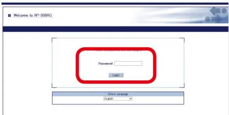
text_image
Welcome to AP-500AC Password Login Select Language English
Note
- For how to display the Web page after the initial configuration, refer to 3-2. Displaying Web Page of AP-500AC (After Initial Configuration).
- Click the band (2.4GHz/5GHz) to use WDS connection from the menu.
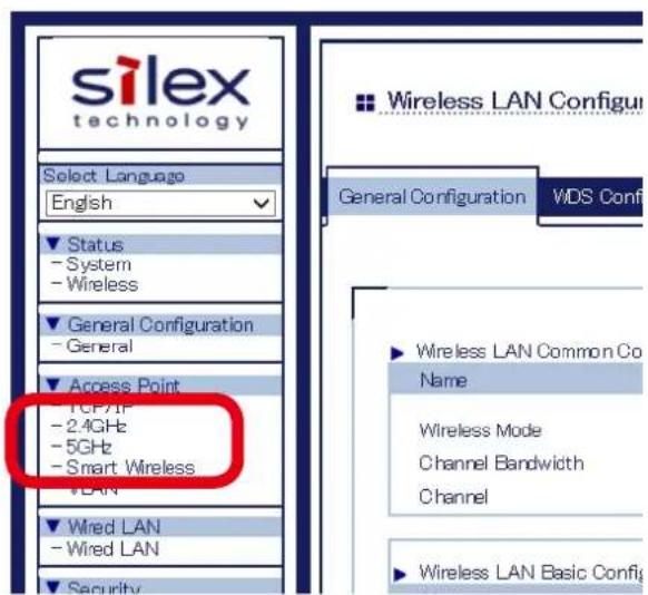
text_image
silex technology Select Language English Status - System - Wireless General Configuration - General Access Point TCP/IP - 2.4GHz - 5GHz - Smart Wireless VLAN Wired LAN - Wired LAN Security Wireless LAN Configur General Configuration WDS Conf ► Wireless LAN Common Co Name Wireless Mode Channel Bandwidth Channel ► Wireless LAN Basic Configur3. Select a wireless interface to use for WDS connection and click WDS Configuration tab.
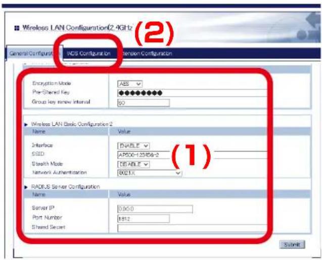
text_image
Wireless LAN Configuration(2.4GHz (2) General Configurist: I/OS Configurist Extension Configurist Encryption Mode ABS Pre-Shared Key Group key new interval 50 ► Wireless LAN Basic Configuration 2 Name Value Interface ENABLE SSD AP500-125B6-2 Stealth Mode TIABLE Network Authentication 9021X ► RADIUS Server Configuration Name Value Server IP 0.050 Port Number 1812 Shared Secret Submit
Note
- For details on each configuration item, refer to A. Appendix - A-1. List of All Settings.
- The wireless settings of the selected interface will be necessary again when you configure Repeater AP.
Please take notes of the settings such as channel, SSID, network authentication, encryption mode, etc.
4. Select Root AP for WDS Mode and select the wireless interface that you have selected to use for WDS connection. Click Submit on the bottom right of Web page.
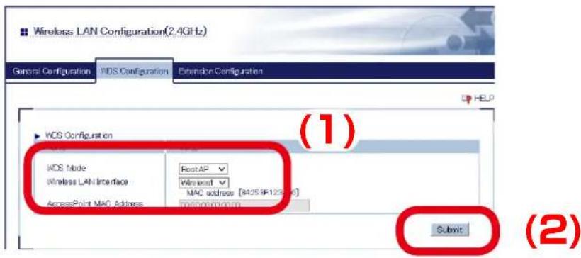
text_image
Wireless LAN Configuration(2.4GHz) General Configuration WDS Configuration Extension Configuration HELP VDS Configuration WDS Mode Wireless LAN Interface AccessPoint MAC Address RestAP Wireless MAC address [8425.9F123.9F] macron.com.cn Submit (1) (2)
Note
- For details on each configuration item, refer to A. Appendix - A-1. List of All Settings.
- The MAC Address displayed under the selected interface will be necessary again when you configure Repeater AP. Please take a note of the MAC Address.
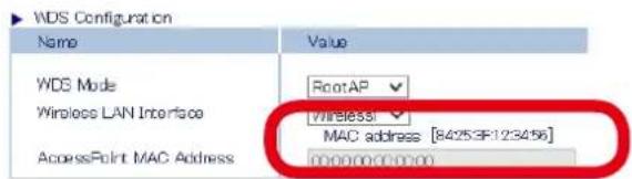
text_image
WDS Configuration Name Value WDS Mode RootAP Wireless LAN Interface Wireless1 MAC address [84253F123456] AccessPoint MAC Address 000000000005. When finished, click Restart.
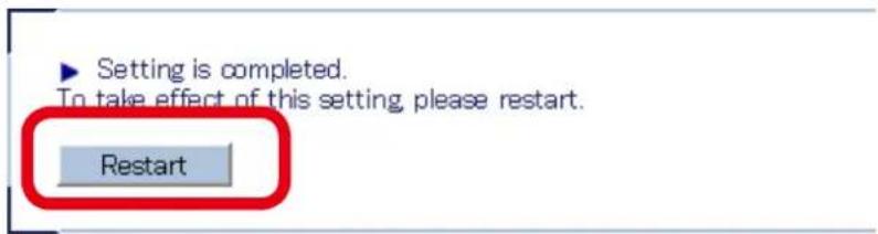
text_image
Setting is completed. To take effect of this setting, please restart. Restart
Note
- If you continue to configure the other settings, you do not have to restart. Please restart when you completed all other settings.
- The WDS setting will not take effect unless you restart AP-500AC.
- If MAC Address filtering is active, it can block access from the Repeater AP's MAC Address. If the Repeater AP is blocked, you will need to change the filter settings at Security - Access Control - MAC Address Filter.
6. After the Restart button is clicked, the progress bar is displayed. When the progress bar reaches the right end, the restart is completed.

text_image
Please wait for a while until the restart is complete.The Root AP setting is completed.
Please continue to Repeater AP configuration.
How to configure Repeater AP:
Set the second or later AP-500AC Access Points as Repeater APs.
The Access Point to connect in WPS can be specified using the MAC Address.
In order to make WDS connection, specify the MAC Address of the host AP to connect in WDS and configure the same wireless settings.
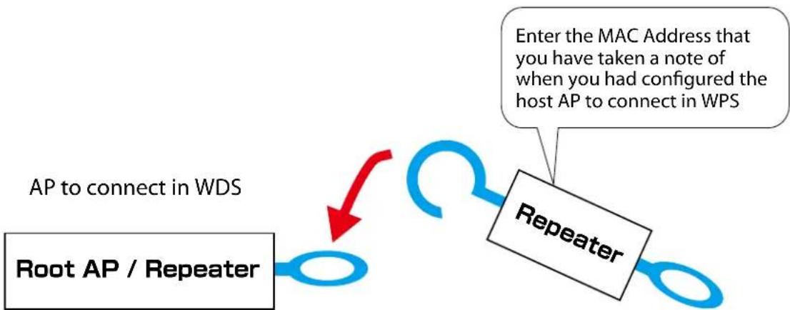
flowchart
graph TD
    A["Root AP / Repeater"] -->|AP to connect in WDS| B["Repeater"]
    B --> C["Enter the MAC Address that you have taken a note of when you had configured the host AP to connect in WPS"]
- Log in to the Web page of AP-500AC to use as Repeater AP using your Web browser.
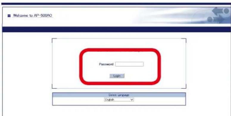
text_image
Welcome to AP-500AC Password Login Select Language English
- For how to display the Web page after the initial configuration, refer to 3-2. Displaying Web Page of AP-500AC (After Initial Configuration).
- Click the band (2.4GHz/5GHz) to use WDS connection from the menu.
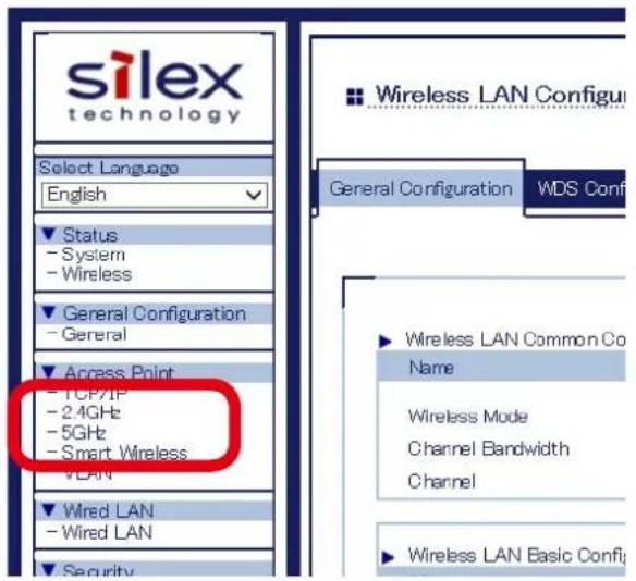
text_image
silex technology Select Language English Status - System - Wireless General Configuration - General Access Point - TCP/IP - 2.4GHz - 5GHz - Smart Wireless VLAN Wired LAN - Wired LAN Security Wireless LAN Configur General Configuration WDS Conf ► Wireless LAN Common Co Name Wireless Mode Channel Bandwidth Channel ► Wireless LAN Basic Confu- Select a wireless interface to use for WDS connection and click WDS Configuration tab.
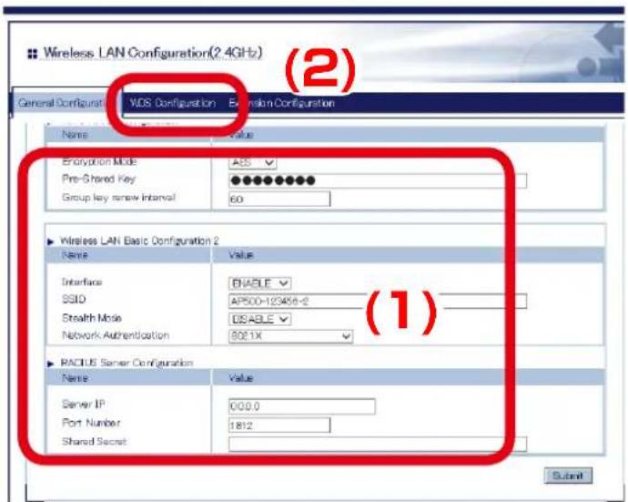
text_image
Wireless LAN Configuration(2.4GHz) General Configuration VIDS Configuration Extension Configuration Name Value Encryption Mode ACS Pre-Shared Key Group key new interval 60 ► Wireless LAN Basic Configuration 2 Name Value Interface ENABLE SSID AP500-123456-2 Stealth Mode DISABLE Network Authentication 8081X ► RADIUS Server Configuration Name Value Server IP 000.0 Port Number 1812 Shared Secret Submit (1)
Note
- For details on each configuration item, refer to A. Appendix - A-1. List of All Settings.
- For the wireless interface, use the same interface as the Root AP which is assigned for WDS connection. Please refer to Step 3 of the Root AP configuration and see the note about wireless settings (channel, SSID, network authentication, and encryption mode).
4. Configure the settings according to the table below and click Submit.
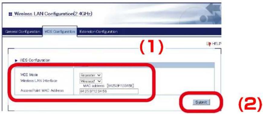
text_image
Wireless LAN Configuration(2.4GHz) General Configuration WDS Configuration Extension Configuration (1) HELP WDS Configuration WDS Mode Wireless LAN Interface AccessPoint MAC Address Repeater Wireless MAC address [84253F123456] 84253F123456 Submit (2)| Name Setting | |
| WDS Mode Repeater | |
| Wireless LAN Interface Select the interface you have selected to use for WDS connection. | |
| Access Point MAC Address | Enter the MAC Address of the host AP to connect in WDS. |

Note
- For details on each configuration item, refer to A. Appendix - A-1. List of All Settings.
- The MAC Address displayed under the selected interface will be necessary again when you configure another Repeater AP. Please take a note of the MAC Address.
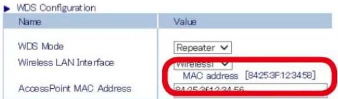
text_image
WDS Configuration Name Value WDS Mode Repeater Wireless LAN Interface Wireless1 MAC address [8425:3F:12:34:58] AccessPoint MAC Address 9425:3612:34:565. When finished, click Restart.
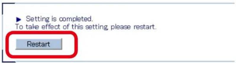
text_image
Setting is completed. To take effect of this setting, please restart. Restart
Note
- If you continue to configure the other settings, you do not have to restart. Please restart when you completed all other settings.
- The WDS setting will not take effect unless you restart AP-500AC.
6. After the Restart button is clicked, the progress bar is displayed. When the progress bar reaches the right end, the restart is completed.

text_image
Please wait for a while until the restart is complete.7. Check that the LED of assigned wireless band turns Orange.
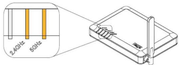
text_image
2.4GHz 5GHzOrange ON : Connected in WDS
AP-500AC

Note
- If the LED of assigned wireless band does not turn Orange, AP-500AC is not connected in WDS.
See 5-4. WDS Feature - What If WDS Connection Fails? for a possible solution.
- WDS connection status can also be checked from the Web page.
For details, refer to 5-4. WDS Feature - Checking WDS Connection Status from Web Page.
The Repeater AP setting is completed.
To connect more Repeater APs in WDS mode, repeat the same process from Step1-7.
What If WDS Connection Fails?
If AP-500AC fails in WDS connection, one of followings might be the reason:
1) The client AP has different wireless settings from the host AP.
2) MAC Address filtering is active on the host AP and it blocks access from the client AP.
3) Too many station devices are connected to the host AP and it has reached the max number of connectable devices.
Follow the instructions below to identify the problems on WDS:
How to check the settings on client AP:
Check the Repeater setting on the client AP.
- Log in to the Web page of AP-500AC (client AP) using your Web browser.
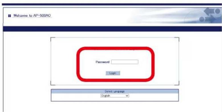
text_image
Welcome to AP-500AC Password Login Select Language English
- For how to display the Web page after the initial configuration, refer to 3-2. Displaying Web Page of AP-500AC (After Initial Configuration).
2. From the left menu in the Web page, click System.
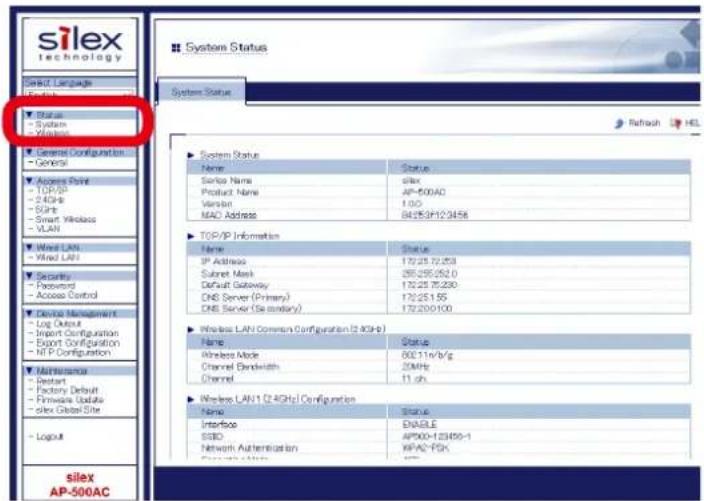
text_image
silex technology Select Language English Status - System - Windows General Configuration - General Access Point - TCP/IP - 2.4GHz - USB - Smart Wireless - VLAN Wired LAN Wired LAN1 Security - Password - Access Control Device Management - Log Output - Import Configuration - Export Configuration - NIP Configuration Maintenance - Restart - Factory Default - Firmware Update - silex Global Site LogM silex AP-500AC System Status Name Status Serial Name silex Product Name AP-500AC Version 1.00 MAC Address 84253F123456 ▶ TOP/IP Information Name Status IP Address 1722572253 Subset Mask 255255252.0 Default Gateway 1722575230 DNS Server (Primary) 17225155 DNS Server (Secondary) 172200100 ▶ Wireless LAN Common Configuration (2.4GHz) Name Status Wireless Mode 600:11nVb/g Channel Bandwidth 25MHz Channel 11 sh. ▶ Wireless LAN1 (2.4GHz) Configuration Name Status Interface ENABLE SSIO APX00-123456-1 Network Authentication KPAC-FSK Server: 100000000000000000000000000000000000000000000000000000000000000000000000000000000000000000000000000003. In the System Status page, check the status information as shown in a table below:
| Setting Item | |
| Wireless LAN Common Configuration | Channel |
| Wireless LAN Configuration Interface | |
| SSID | |
| Network Authentication | |
| Encryption Mode | |
| WDS Information WDS Mode | |
| Wireless Interface |
The MAC Address used to connect to the host AP in WDS is displayed at WDS Mode under WDS Information.

text_image
WDS Information (24GHz) Name Status WDS Mode Repeater [90:25:3F 12:34:58] Wireless LAN Interface Wireless LAN [A5500-123455-1] AccessPoint MAC Address — Wireless Signal Strength(dBm) —
Note
- For details on each configuration item, refer to A. Appendix - A-1. List of All Settings.
- The confirmed status information will be necessary again when you check the settings on the host AP.
Please take notes of the wireless settings such as channel, SSID, network authentication, encryption mode, etc. and the MAC Address.
How to check the settings on host AP:
Check the Root AP or Repeater AP settings of the host AP.
- Log in to the Web page of AP-500AC (host AP) using your Web browser.
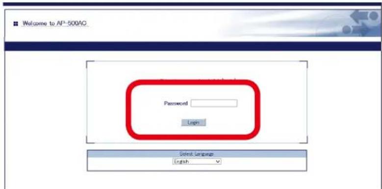
text_image
Welcome to AP-500AC Password Login Select Language English
Note
- For how to display the Web page after the initial configuration, refer to 3-2. Displaying Web Page of AP-500AC (After Initial Configuration).
- From the left menu in the Web page, click System.
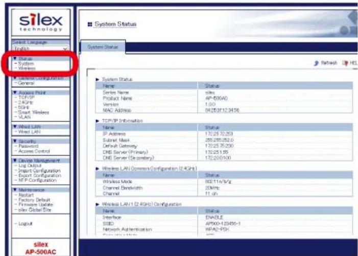
text_image
silex technology Select Language English Status - System - Wireless Language Configuration - General Access Point - TCP/IP - 2.4GHz - SDH - Smart Wireless - VLAN Wired LAN - Wired LAN Security - Password - Access Control Device Management - Log Output - Import Configuration - Export Configuration - NTP Configuration Maintenance - Report - Factors Default - Firmware Update - silex Global Site - Logout silex AP-500AC System Status Name Status Series Name siles Product Name AP-50040 Version 1.00 MAC Address 042637123456 TCP/IP Information Name Status IP Address 1702570.253 Submit Mask 250255.252.0 Default Gateway 1702575.250 DNS Server (Primary) 170251.85 DNS Server (Secondary) 170250.100 Wireless LAN Common Configuration (2.4GHz) Name Status Wireless Mode 80:11n/3/s Channel Bandwidth 2GHz Channel 11 sh Wireless LAN1 (2.4GHz) Configuration Name Status Interface ENABLE SSID AP500-123456-1 Network Authentication KEPA2-FCK Data Centers 1003. In the System Status page, check that WDS Mode is set to Root AP or Repeater.
Check that status information as show in a table below are the same as those you previously checked at the client AP.
| Setting Item | |
| Wireless LAN Common Configuration Channel | |
| Wireless LAN Configuration Interface | |
| SSID | |
| Network Authentication | |
| Encryption Mode | |
| WDS Information Wireless Interface | |

Note
- For details on each configuration item, refer to A. Appendix - A-1. List of All Settings.
- If the settings are different between the host AP and client AP, change the settings of client AP to match those of host AP. For how to change the settings, refer to 5-4 WDS Feature - WDS Configuration.
4. From the left menu in the Web page, click Access Control - MAC Address Filter.
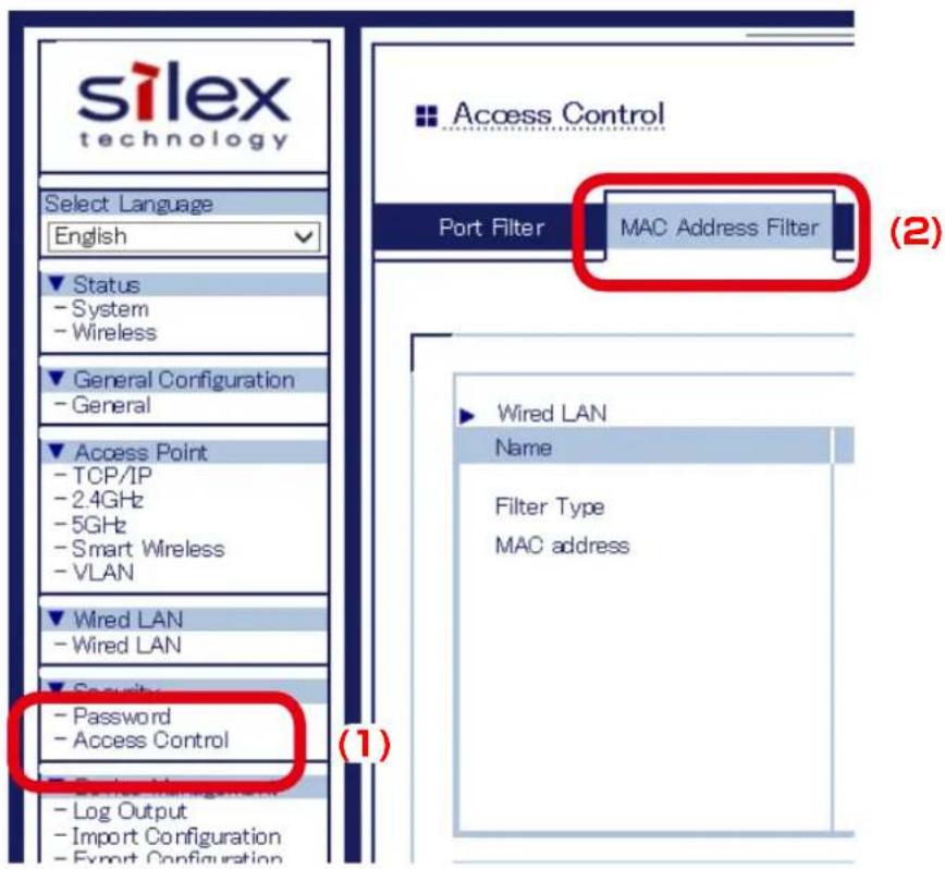
text_image
silex technology Select Language English Status - System - Wireless General Configuration - General Access Point - TCP/IP - 2.4GHz - 5GHz - Smart Wireless - VLAN Wired LAN - Wired LAN Security - Password - Access Control - Log Output - Import Configuration - Export Configuration Port Filter MAC Address Filter (1) (2) Wired LAN Name Filter Type MAC address- Select the wireless interface assigned for WDS connection and check that the MAC Address filter is not set to block access from the client AP.
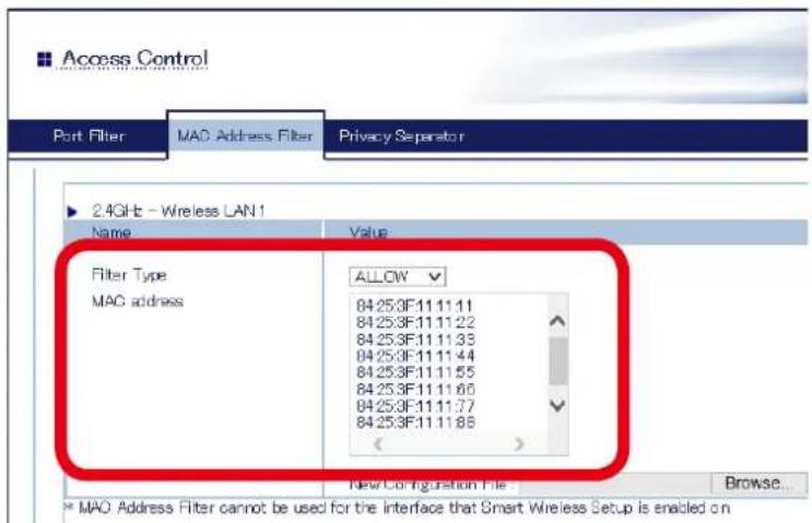
text_image
Access Control Port Filter MAC Address Filter Privacy Separator 2.4GHz - Wireless LAN1 Name Value Filter Type ALLOW MAC address 84253F111111 84253F111122 84253F111133 84253F111144 84253F111155 84253F111160 84253F111177 84253F111188 (< ) New Configuration File Browse... * MAO Address Filter cannot be used for the interface that Smart Wireless Setup is enabled on
Note
- For details on each configuration item, refer to A. Appendix - A-1. List of All Settings.
- The client AP connects to the host AP using the "MAC Address used to connect to host AP in WDS" that you have previously checked at the client AP. If access from the client AP is denied, change the setting to allow it.
- From the left menu in the Web page, click System. In the System Status page, check the Encryption Mode used for the wireless LAN.
The max number of connectable devices for AP-500AC will differ depending on the encryption mode used. Please check that too many station devices or APs exceeding that number are not connected in your environment.
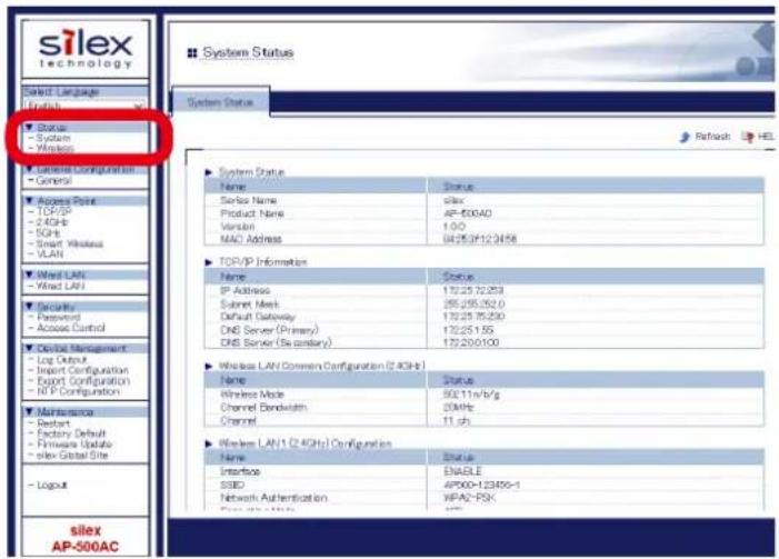
text_image
silex technology Select Language English Status - System - Wireless Latellite Configuration - General Access Point - TCP/IP - 2.4GHz - SGB - Smart Wireless - VLAN Wired LAN - Wired LAN Security - Password - Access Control Device Management - Log Output - Import Configuration - Export Configuration - ITP Configuration Maintenance - Report - Factory Default - Firmware Update - slex Global Site - Logout silex AP-500AC System Status System Status Name Status Serial Name silex Product Name AP-500AD Version 1:00 NAD Address 04/25/3F12/2458 TOP/IP Information Name Status IP Address 172/25 72.253 Subnet Mesh 255/25.252.0 Default Gateway 172/25 75.230 DNS Server (Primary) 172/25 155 DNS Server (Secondary) 172/200.100 Wireless LAN Common Configuration (2.4GHz) Name Status Wireless Mode 90CL1n/V/g Channel Bandwidth 20MHz Channel 11.6J Wireless LAN1 (2.4GHz) Configuration Name Status Interface ENABLE SSD AP500+123456-1 Network Authentication WPAQ-FSK
Note
- For details on each configuration item, refer to A. Appendix - A-1. List of All Settings.
- The max number of connectable station devices will differ depending on the encryption mode used.
- When using AES only: 100 units
- When using TKIP or AUTO: 50 units
- In Multi SSID environment, the number of connected devices will be the total number of devices connected on all wireless interfaces. Thus, the max number of connectable devices will differ depending on the encryption mode used on each interface.
- When all wireless interfaces use AES only: 100 units
- When one or some of the wireless interfaces use TKIP or AUTO: 50 units
- When using the WDS feature, the Repeater AP connected to AP-500AC as a client AP will consume one of the available connections, while Root AP or Repeater APs connected to AP-500AC as a host AP will NOT consume any connections.
Checking WDS Connection Status from Web Page
To see if AP-500AC is connected in WDS mode properly, check the status page on the Web page in the order from the client (Repeater AP) to the host (Root AP or Repeater AP). In the Web page, the host AP connected in WDS is displayed.
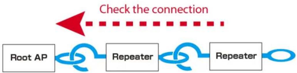
flowchart
graph LR
    A["Root AP"] --> B["Repeater"]
    B --> C["Repeater"]
    C --> D["Check the connection"]
How to check the WPS connection to the host AP:
- Log in to the Web page of the Repeater AP using your Web browser.
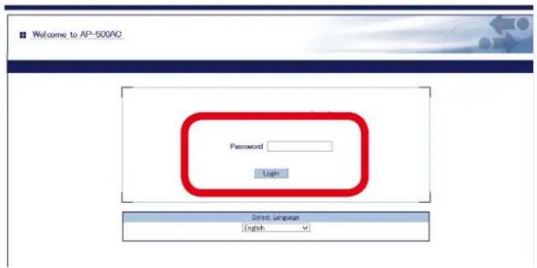
text_image
Welcome to AP-500AC Password Login Gyest Language English
Note
- For how to display the Web page after the initial configuration, refer to 3-2. Displaying Web Page of AP-500AC (After Initial Configuration).
2. From the left menu in the Web page, click System.
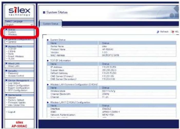
text_image
silex technology Select Language English Status - System - Wireless General Access Point - TOP/IP - 2.4GHz - SGPs - Smart Wireless - VLAN Wired LAN - Wired LAN Security - Password - Access Control Device Management - Log Output - Input Configuration - Export Configuration - NIP Configuration Maintenance - Report - Factories Default - Firmware Update - Sites Global Site - Logout silex AP-500AC System Status System Status Name Status Serial Name Silex Product Name AP-500AC Version 1:00 MAC Address 04250/123456 TOP/IP Information Name Status IP Address 1722572253 Submit Mask 255255250.0 Default Gateway 1722575230 DNS Server (Primary) 17225195 DNS Server (Secondary) 172200100 Wireless LAN1 Common Configuration (2 GHz) Name Status Wireless Mode 80E11n/kg Channel Bandwidth 20MHz Channel 11 sh Wireless LAN1 (2.4GHz) Configuration Name Status Interface ENABLE SSD AP500+123456-1 Network Authentication MPA2-PSK Silex AP-500AC3. In the System Status page, check the WDS Information.
If Access Point MAC Address and Wireless Signal Strength(dBm) are displayed, the WDS connection is established successfully.
To continue to see the connection status at the host AP, repeat the same process from Step1-3 at the host AP's Web page.
WDS Connection Success:

text_image
WDS Information (2.4GHz) Name Status WDS Mode Repeater [96:25:3F:12:34:58] Wireless LAN Interface Wireless LAN1 [AP500-123456-1] AccessPoint MAC Address 84:25:3F:12:34:56 Wireless Signal Strength(dBm) (-24)WDS Connection Failure:

text_image
WDS Information (2.4GHz) Name Status WDS Mode Repeater [96:25:3F:12:34:58] Wireless LAN Interface Wireless LAN1 [AP500-123456-1] AccessPoint MAC Address — Wireless Signal Strength(dBm) —
Note
- For details on each configuration item, refer to A. Appendix - A-1. List of All Settings.
- If Access Point MAC Address and Wireless Signal Strength (dBm) are not displayed, the WDS connection is not established. In such a case, refer to 5-4. WDS Feature - What If WDS Connection Fails? for possible solutions.
- In the Web page of Root AP, Access Point MAC Address and Wireless Signal Strength (dBm) are not displayed.

Note
- AP-500AC uses two MAC Addresses for the WDS connection.
- The MAC Address used to connect to the host AP in WDS is displayed in the System Status page.
- The MAC Address of the wireless interface is displayed in WDS Configuration tab of Wireless LAN Configuration page. This will be the MAC Address of the wireless interface assigned for WDS connection.
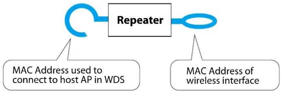
flowchart
graph TD
    A["Repeater"] --> B["MAC Address used to connect to host AP in WDS"]
    A --> C["MAC Address of wireless interface"]

text_image
WDS Information(2.4GHz) Name Status WDS Mode Repeater (9625CF-123456) Wireless LAN Interface Wireless LAN [AP500-123456-1] AccessPoint MAD Address Wireless Signal Strength(HdBm) (-24)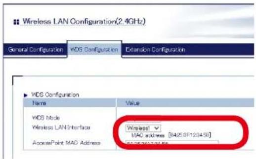
text_image
Wireless LAN Configuration(2.4GHz) General Configuration WDS Configuration Extension Configuration WDS Configuration Name Value WDS Mode Wireless LAN Interface AccessPoint MAC Address Wireless MAC address [8425.8F120458] G425.8F120458- When connected in WDS, the Wireless Station Status page of the host AP shows a list of connected client AP.
- The IP Address of the client AP is not displayed.
- The MAC Address of the client AP will be the MAC Address which the client AP uses to connect to the host AP in WDS mode.
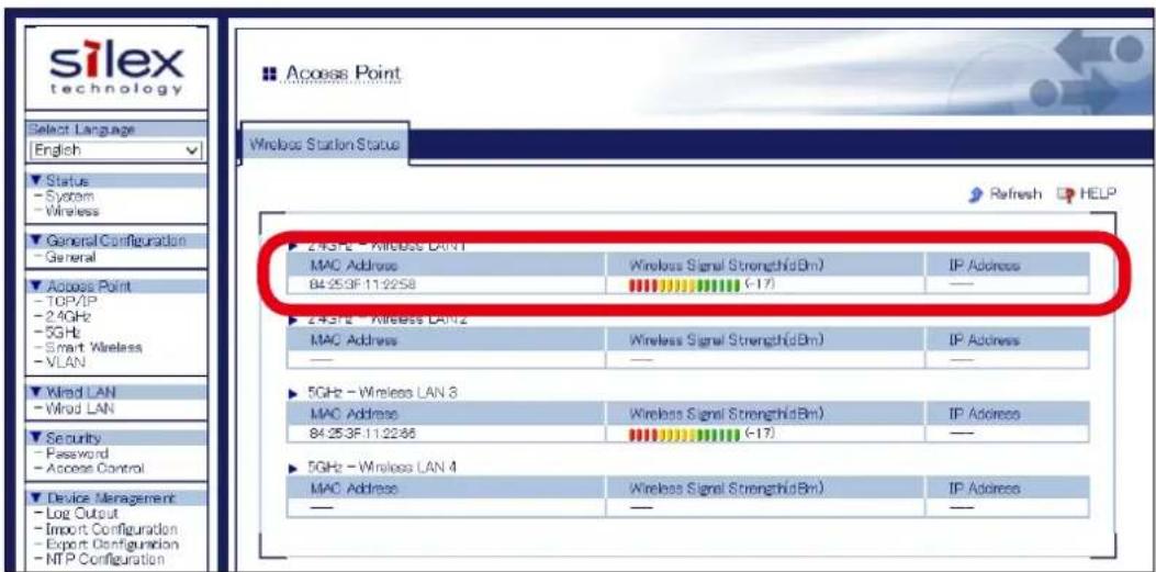
text_image
silex technology Select Language English Status - System - Wireless General Configuration - General Access Point - TOP/IP - 2.4GHz - 5GHz - Smart Wireless - VLAN Wired LAN - Wired LAN Security - Password - Access Control Device Management - Log Output - Import Configuration - Export Configuration - NTP Configuration Access Point Windows Station Status Refresh HELP 243FE - Wireless LAN1 MAC Address 84:25:3F 11:22:58 Wireless Signal Strength(dBm) (-17) IP Address - 243FE - Wireless LAN2 MAC Address - Wireless Signal Strength(dBm) - IP Address - 5GHz - Wireless LAN 3 MAC Address 84:25:3F 11:22:66 Wireless Signal Strength(dBm) (-17) IP Address - 5GHz - Wireless LAN 4 MAC Address - Wireless Signal Strength(dBm) - IP Address -5-5. VLAN Feature
A VLAN ID can be set to the SSID of wireless LAN structured by AP-500AC.
If AP-500AC is used with the switching HUB that supports tagged-VLAN (hereinafter the "VLAN HUB"), you can establish the virtual network groups.
As AP-500AC supports Multi SSID, up to 4 virtual network groups can be established.
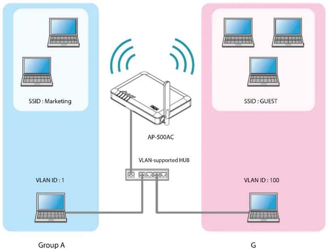
flowchart
graph TD
    subgraph_Group_A["Group A"]
        A1["Computer"] --> AP["AP-500AC"]
        A2["Computer"] --> AP
        A3["Computer"] --> AP
        A4["Computer"] --> AP
        A5["Computer"] --> AP
        A6["Computer"] --> AP
        A7["Computer"] --> AP
        A8["Computer"] --> AP
        A9["Computer"] --> AP
        A10["Computer"] --> AP
        A11["Computer"] --> AP
    end

    subgraph_Group_B["Group B"]
        B1["Computer"] --> AP
        B2["Computer"] --> AP
        B3["Computer"] --> AP
        B4["Computer"] --> AP
        B5["Computer"] --> AP
        B6["Computer"] --> AP
        B7["Computer"] --> AP
        B8["Computer"] --> AP
        B9["Computer"] --> AP
    end

    AP -->|VLAN-supported HUB| B
    AP -->|VLAN - 1| A1
    AP -->|VLAN - 1| A2
    AP -->|VLAN - 1| A3
    AP -->|VLAN - 1| A4
    AP -->|VLAN - 1| A5
    AP -->|VLAN - 1| A6
    AP -->|VLAN - 1| A7
    AP -->|VLAN - 1| A8
    AP -->|VLAN - 1| A9
    AP -->|VLAN - 1| A10
    AP -->|VLAN - 1| A11
    AP -->|VLAN - 1| A12
    AP -->|VLAN - 1| A13
    AP -->|VLAN - 1| A14
    AP -->|VLAN - 1| A15
    AP -->|VLAN - 1| A16
    AP -->|VLAN - 1| A17
    AP -->|VLAN - 1| A18
    AP -->|VLAN - 1| A19
    AP -->|VLAN - 1| A20
    AP -->|VLAN - 1| A21
    AP -->|VLAN - 1| A22
    AP -->|VLAN - 1| A23
    AP -->|VLAN - 1| A24
    AP -->|VLAN - 1| A25
    AP -->|VLAN - 1| A26
    AP -->|VLAN - 1| A27
    AP -->|VLAN - 1| A28
    AP -->|VLAN - 1| A29
    AP -->|VLAN - 1| A30
    AP -->|VLAN - 1| A31
    AP -->|VLAN - 1| A32
    AP -->|VLAN - 1| A33
    AP -->|VLAN - 1| A34
    AP -->|VLAN - 1| A35
    AP -->|VLAN - 1| A36
    AP -->|VLAN - 1| A37
    AP -->|VLAN - 1| A38
    AP -->|VLAN - 1| A39
    AP -->|VLAN - 1| A40
    AP -->|VLAN - 1| A41
    AP -->|VLAN - 1| A42
    AP -->|VLAN - 1| A43
    AP -->|VLAN - 1| A44
    AP -->|VLAN - 1| A45
    AP -->|VLAN - 1| A46
    AP -->|VLAN - 1| A47
    AP -->|VLAN - 1| A48
    AP -->|VLAN - 1| A49
    AP -->|VLAN - 1| A50
    AP -->|VLAN - 1| A51
    AP -->|VLAN - 1| A52
    AP -->|VLAN - 1| A53
    AP -->|VLAN - 1| A54
    AP -->|VLAN - 1| A55
    AP -->|VLAN - 1| A56
    AP -->|VLAN - 1| A57
    AP -->|VLAN - 1| A58
    AP -->|VLAN - 1| A59
    AP -->|VLAN - 1| A60
    AP -->|VLAN - 1| A61
    AP -->|VLAN - 1| A62
    AP -->|VLAN - 1| A63
    AP -->|VLAN - 1| A64
    AP -->|VLAN - 1| A65
    AP -->|VLAN - 1| A66
    AP -->|VLAN - 1| A67
    AP -->|VLAN - 1| A68
    AP -->|VLAN - 1| A69
    AP -->|VLAN - 1| A70
Establish the Virtual Network Groups

TIP
- AP-500AC supports the tagged VLAN of IEEE802.1Q compliant.
- Dynamic VLAN is not included.
VLAN Configuration
The following explains how to install AP-500AC to where network groups have already been established using a VLAN HUB.
How to check the VLAN information on network:
Check the information below of the existing network.
For details on the VLAN HUB specifications, please see the operation manual that came with your VLAN HUB.
- Position of a trunk port on the VLAN HUB
- VLAN ID of the native VLAN
- VLAN ID of the devices connected to VLAN HUB

flowchart
graph TD
    A["Trunk Port"] --> B["VLAN HUB"]
    C["VLAN ID: 1"] --> B
    D["VLAN ID: 200"] --> B
    E["VLAN ID: 100"] --> B

- If there is no available trunk port on the VLAN HUB, create a new one.
- For details on VLAN HUB specifications, please see the operation manual that came with your VLAN HUB.

- The native VLAN is also referred to as untagged VLAN.
Note
How to configure the VLAN setting on AP-500AC:
1. Log in to the Web page of AP-500AC using your Web browser.
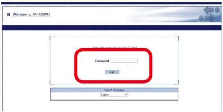
text_image
Welcome to AP-500AG Enter the account and click files! Password Login Select Language English
- When using a VLAN HUB during the configuration, please make sure that you connect AP-500AC to the port that can communicate with your PC.

- For how to display the Web page after the initial configuration, refer to 3-2. Displaying Web Page of AP-500AC (After Initial Configuration).
2. From the left menu in the Web page, click VLAN.

text_image
silex technology Select Language English Status - System - Wireless General Configuration - General Access Point - TCP/IP - 2.4GHz - 5GHz - Smart Wireless - VLAN Wired LAN Security - Password VLAN Configurati VLAN Configuration IEEE802.1Q VLAN C Name VLAN Native VLAN ID 2.4GHz WirelessLAN 2.4GHz WirelessLAN 5GHz WirelessLAN 5GHz WirelessLAN3. If VLAN is set to ENABLE, the VLAN ID settings will become active.
Configure the VLAN ID appropriate for virtual network you wish to establish according to the existing network settings you have checked in advance.
When finished, click Submit.
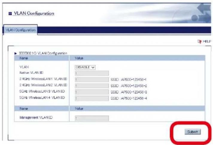
text_image
VLAN Configuration VLAN Configuration IEEE80.1G VLAN Configuration Name Value VLAN DISABLE Native VLAN ID 1 24GHz WirelessLAN1 VLANID 1 SSID: AP500-123456-1 24GHz WirelessLAN2 VLANID 1 SSID: AP500-123456-2 5GHz WirelessLAN3 VLANID 1 SSID: AP500-123456-3 5GHz WirelessLAN4 VLANID 1 SSID: AP500-123456-4 Name Value Management VLAN ID 1 SubmitSample setting
| VLAN ID SSID | ||
| Wireless LAN1 | 1 MARKETING | |
| Wireless LAN2 | 100 GUEST | |
| Wireless LAN3 | 200 SALES | |

- For the Management VLAN ID, when VLAN feature is enabled and one of following authentication modes is set for Network Authentication, enter the same VLAN ID as that of network group where the RADIUS server is installed.
- 802.1X - WPA-Enterprise - WPA2-Enterprise - WPA/WPA2-Enterprise

Note
- For details on each configuration item, refer to A. Appendix - A-1. List of All Settings.
- For Native VLAN ID, enter the native VLAN ID of VLAN HUB that you have checked beforehand.
- For VLAN ID of the wireless LAN 1-4, enter VLAN ID of the devices connected to the HUB that you have checked beforehand.
- After VLAN feature is enabled, you will not be able to configure AP-500AC via the network with a different VLAN ID from management VLAN ID.
- When VLAN feature is set to ENABLE, the VLAN ID can also be configured from the wireless general configuration page.
- Even when VLAN feature is enabled, access from non-VLAN HUB is accepted if the same VLAN ID is set for both Native VLAN ID and Management VLAN ID. It is recommended to set a same VLAN ID for both of these.
4. When finished, click Restart.
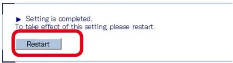
text_image
Setting is completed. To take effect of this setting, please restart. Restart
Note
- If you continue to configure the other settings, you do not have to restart. Please restart when you completed all other settings.
- The VLAN setting will not take effect unless you restart AP-500AC.
5. After the Restart button is clicked, the progress bar is displayed. When the progress bar reaches the right end, the restart is completed.

text_image
Please wait for a while until the restart is complete.How to connect AP-500AC to a trunk port of VLAN HUB:
Connect a wired LAN port of AP-500AC and a trunk port of VLAN HUB (that you have checked beforehand) using a network cable.
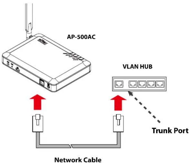
text_image
AP-500AC VLAN HUB Trunk Port Network CableThe VLAN configuration is completed.
The virtual network groups will be active based on the VLAN ID setting you configured.
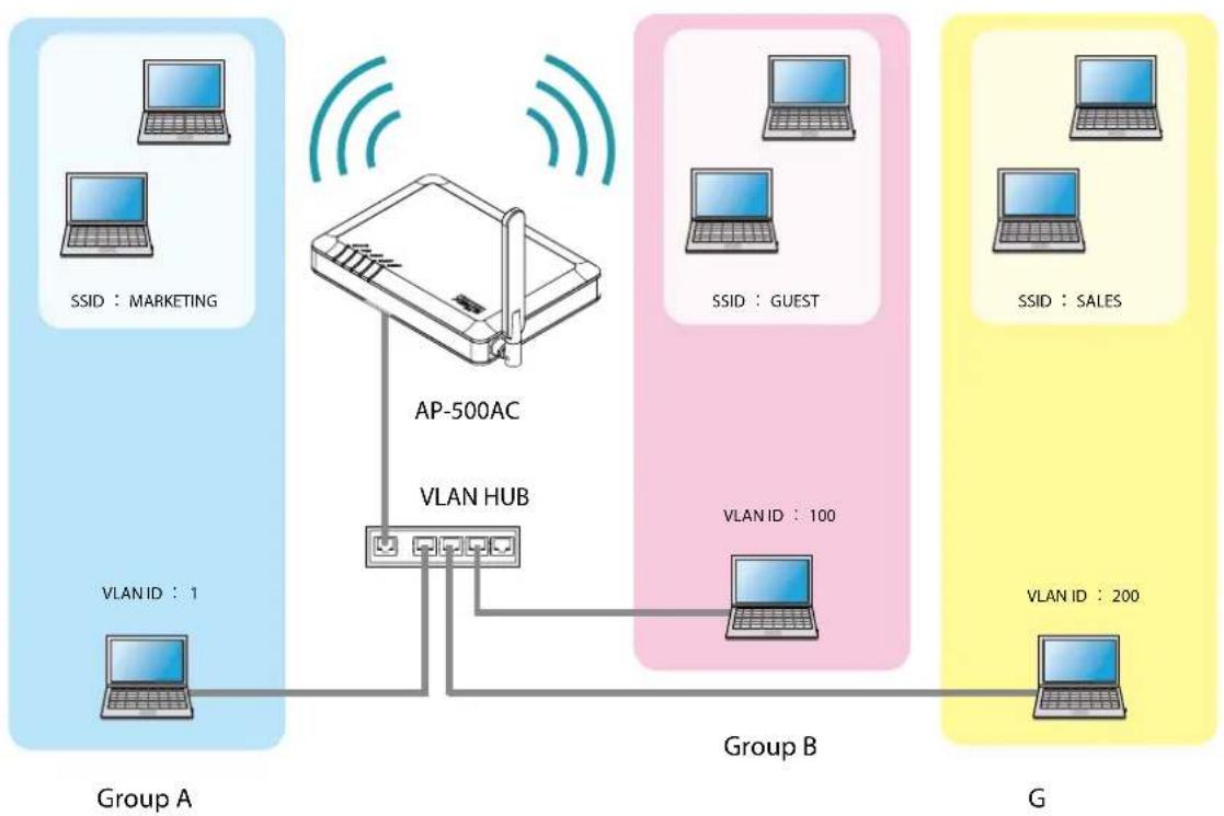
flowchart
graph TD
    subgraph_Group_A["Group A"]
        A1["SSID : MARKETING"] --> AP["AP-500AC"]
        A2["VLAN ID : 1"] --> AP
        AP -->|VLAN HUB| B1["Group B"]
    end

    subgraph_Group_B["Group B"]
        B1 -->|VLAN ID : 100| C1["Group B"]
        C1 -->|VLAN ID : 200| D1["Group G"]
    end

    subgraph_Group_B_G["Group B"]
        D1 -->|VLAN ID : 200| E1["Group B"]
        E1 -->|VLAN ID : 200| F1["Group G"]
    end

    AP -->|VLAN HUB| B1
    AP -->|VLAN HUB| C1
    style AP fill:#f9f,stroke:#333
    style Group_B fill:#ccf,stroke:#333
    style Group_B_G fill:#cfc,stroke:#333
Establish the Virtual Network Groups

- After the VLAN feature is enabled, you will not be able to configure AP-500AC via the network with a different VLAN ID from management VLAN ID. If you are not sure of the VLAN ID of the management VLAN, you will need to initialize the settings and reconfigure AP-500AC. For how to initialize AP-500AC, refer to Chapter 5-11 Maintenance Feature - How to reset AP-500AC to factory defaults using the Push Switch.
- To configure AP-500AC wirelessly from a PC running on VLAN-enabled environment, the VLAN ID configured to SSID of the wireless LAN must be the same as management VLAN ID. By defaults, the configuration change via wireless LAN is restricted on AP-500AC since the Access Control feature is on. Please change the setting appropriate for your environment.
- For details on each configuration item, refer to A. Appendix - A-1. List of All Settings.
5-6. Mac Address Filter
It is possible to block access from particular devices to AP-500AC. MAC Address filter can respectively be set for a wired LAN and wireless interface.
Filter Type
By registering the MAC Address to a list, access of devices is allowed or denied based on the filter type below.
| Name Description |
| DISABLE Does not use MAC Address filter. All devices are allowed to access. |
| ALLOW Allows access only from devices with the registered MAC Address. |
| DENY Denies access from devices with the registered MAC Address. |

- If Smart Wireless Setup is enabled on the wireless interface, MAC Address filtering cannot be used on that interface. In order to use MAC Address filtering, disable Smart Wireless Setup or select the wireless interface which does not have MAC Address filter setting at Smart Wireless Setup tab.
MAC Address List
Register the MAC Address of devices to allow/deny access to AP-500AC.
To register, create a list of MAC Addresses as a text file and import it to AP-500AC from the Web page.
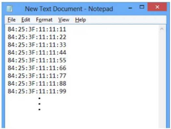
text_image
84:25:3F:11:11:11 84:25:3F:11:11:22 84:25:3F:11:11:33 84:25:3F:11:11:44 84:25:3F:11:11:55 84:25:3F:11:11:66 84:25:3F:11:11:77 84:25:3F:11:11:88 84:25:3F:11:11:99 • • •
Note
- Create the MAC Address list as a text file using an editor, etc. and save it with any file name.
- In MAC Address list, one MAC Address needs to be described per line.
- Below is the number of MAC Addresses that can be registered for each wired LAN and wireless interface.
Wired LAN: 32 addresses
Wireless LAN: 100 addresses
MAC Address Filter Setting
Following explains how to configure the MAC Address filter.
- Log in to the Web page of AP-500AC using your Web browser.
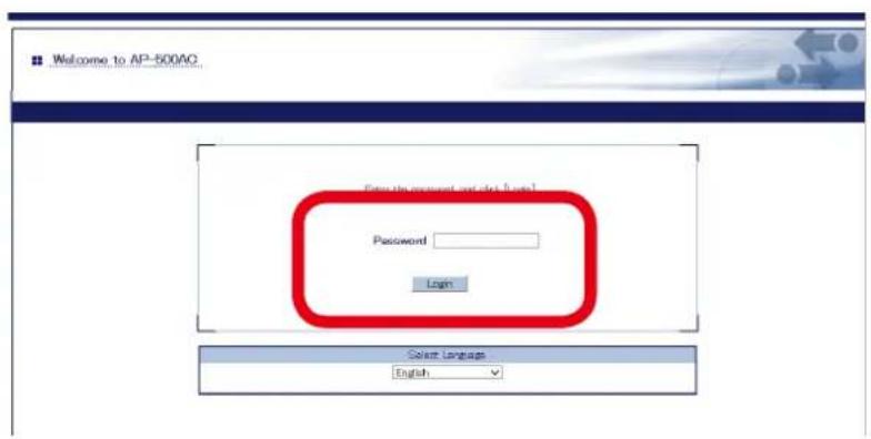
text_image
Welcome to AP-500AC Password Login Select Language English
Note
- For how to display the Web page after the initial configuration, refer to 3-2. Displaying Web Page of AP-500AC (After Initial Configuration).
- From the left menu in the Web page, click Access Control - MAC Address Filter.
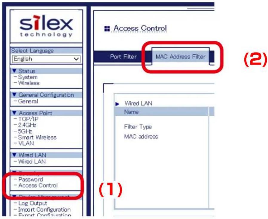
text_image
silex technology Select Language English Status - System - Wireless General Configuration - General Access Point - TCP/IP - 2.4GHz - 5GHz - Smart Wireless - VLAN Wired LAN - Wired LAN Password - Access Control Log Output - Import Configuration - Export Configuration Access Control Port Filter MAC Address Filter Wired LAN Name Filter Type MAC address (1) (2)- Select a filter type for the interface to use MAC Address filter. Click Browse and select a file of MAC Address list.
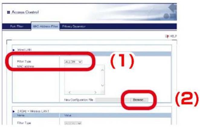
text_image
Access Control Port Filter MAC Address Filter Privacy Separator HELP Wind LAN Filter Type ALLOW MAC address New Configuration File Browse (1) (2) 24GHz - Wireless LAN 1 Name Value Filter Type Allowable
- If Smart Wireless Setup is enabled on the wireless interface, MAC Address filtering cannot be used.
Note
- When the filter type is selected and the file of MAC Address list is selected for all interfaces to use MAC Address filter, click Submit.
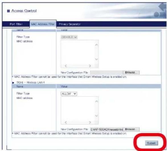
text_image
Access Control Port Filter MAC Address Filter Privacy Separator Name Filter Type MAC address Value DEFAULT New Configuration File Browse... MAC Address Filter cannot be used for the Interface that Smart Wireless Setup is enabled on. 50GB - Wireless LAN 4 Name Value Filter Type MAC address ALLOW New Configuration File C:\MP-500\MAC\msadded.txt Browse... MAC Address Filter cannot be used for the Interface that Smart Wireless Setup is enabled on. Cuben
Note
- After Submit is clicked, MAC Address information of the imported file is displayed on the list of Web page.
- When a file of MAC Address list contains a number of addresses that exceeds the maximum number of registerable addresses on each interface, error message will appear.
-
It is impossible to edit the MAC Address information on Web page. To add or remove the address, edit a file of MAC Address list and import it again.
-
A confirmation message is displayed. Click OK.
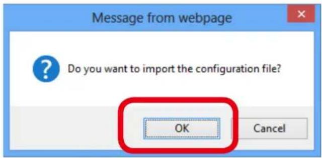
text_image
Message from webpage Do you want to import the configuration file? OK Cancel- When finished, click Restart.
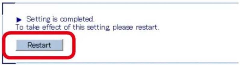
text_image
Setting is completed. To take effect of this setting, please restart. Restart
- If you continue to configure the other settings, you do not have to restart. Please restart when you completed all other settings.
-
The MAC Address Filter setting will not take effect unless you restart AP-500AC.
-
After the Restart button is clicked, the progress bar is displayed. When the progress bar reaches the right end, the restart is completed.

text_image
Please wait for a while until the restart is complete.5-7. Device Server Feature
The USB devices connected to AP-500AC can be shared over the network.
To use the device server feature, the USB connection utility, "SX Virtual Link" is required.
How to install and use SX Virtual Link is as follows:

- SX Virtual Link is also used for the log output feature.
Note
Connect the USB device that you wish to share over the network to the USB port of AP-500AC.
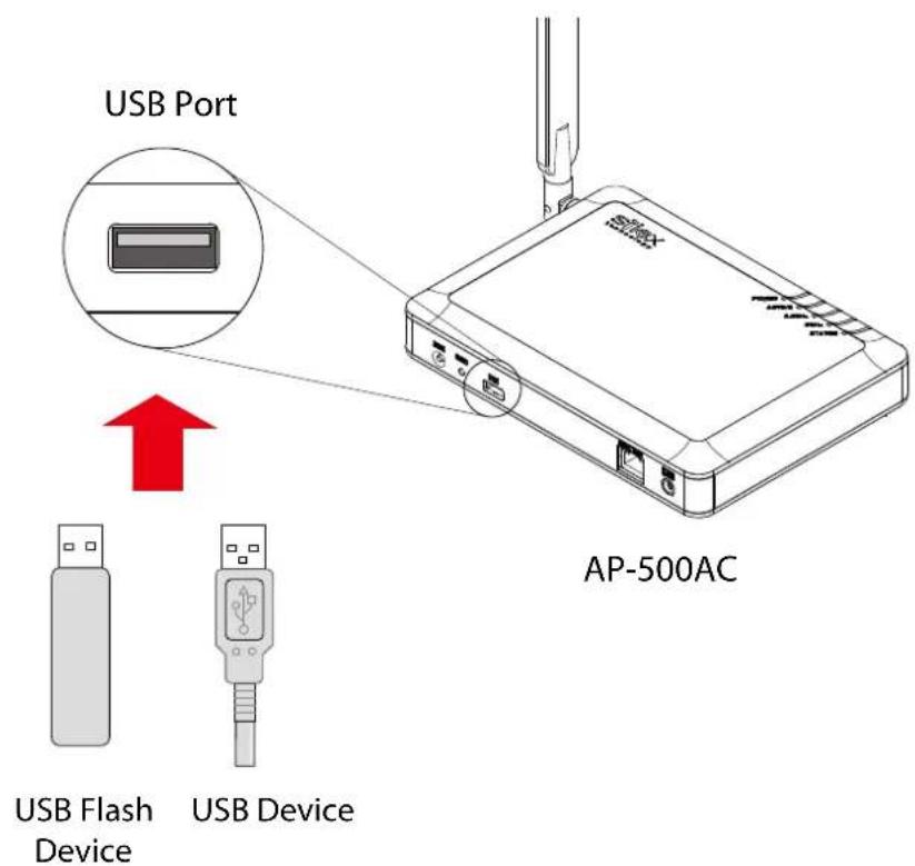
text_image
USB Port AP-500AC USB Flash Device USB DeviceDownloading & Installing SX Virtual Link
What is SX Virtual Link?
SX Virtual Link allows you to connect your PC to a USB device that is connected to AP-500AC. Use SX Virtual Link when you connect/disconnect to/from the USB device.
AP-500AC allows you to use USB devices as if they were connected directly to your PC.
How to download SX Virtual Link:
- Access our website below.
| URL | |
| USA http://www.silexamerica.com/ | |
| Europe http://www.silexeurope.com/ |
- Go to the support section and download SX Virtual Link.
How to install SX Virtual Link:

- Administrator privilege is required for installation.
- Decompress the file you have downloaded and then double-click Cosetup.exe.
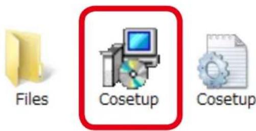
text_image
Files Cosetup Cosetup-
The User Account Control message is displayed, click Yes.
-
SX Virtual Link installer is started and the language selection menu is displayed. Select English and click Next.
-
SX Virtual Link installer is started and the language selection menu is displayed. Select English and click Next.
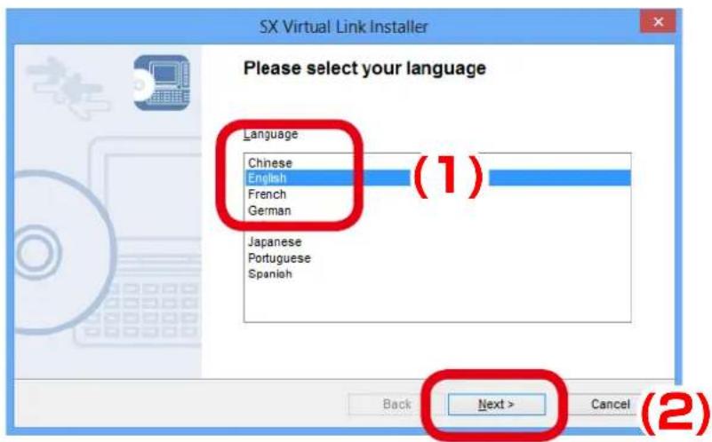
text_image
SX Virtual Link Installer Please select your language Language Chinese English French German (1) Japanese Portuguese Spanish Back Next > Cancel (2)4. Click Next.
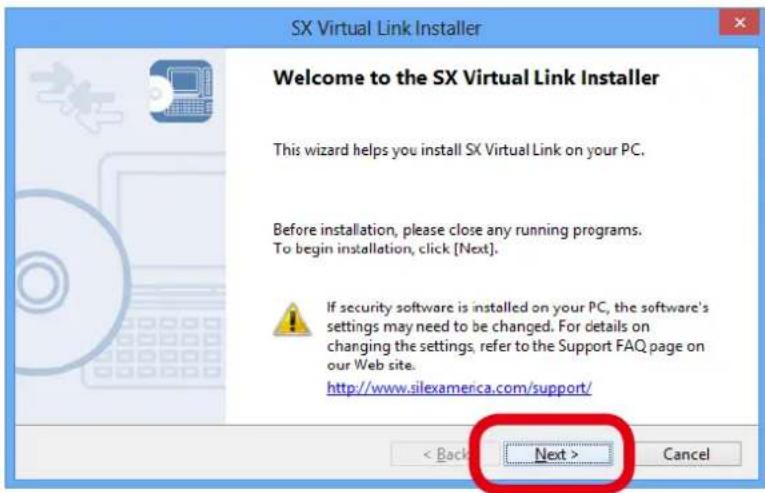
text_image
SX Virtual Link Installer Welcome to the SX Virtual Link Installer This wizard helps you install SX Virtual Link on your PC. Before installation, please close any running programs. To begin installation, click [Next]. If security software is installed on your PC, the software's settings may need to be changed. For details on changing the settings, refer to the Support FAQ page on our Web site. http://www.silexamerica.com/support/ < Back Next > Cancel5. Read the SOFTWARE LICENSE AGREEMENT and click Yes.
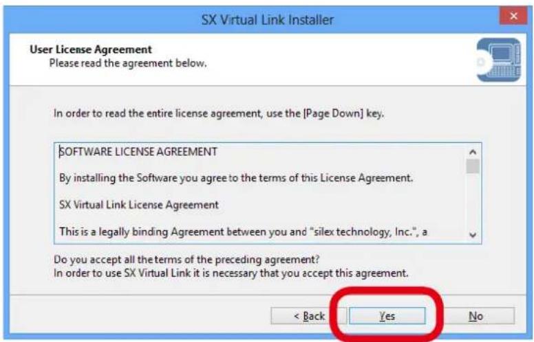
text_image
SX Virtual Link Installer User License Agreement Please read the agreement below. In order to read the entire license agreement, use the [Page Down] key. SOFTWARE LICENSE AGREEMENT By installing the Software you agree to the terms of this License Agreement. SX Virtual Link License Agreement This is a legally binding Agreement between you and "silex technology, Inc.", a Do you accept all the terms of the preceding agreement? In order to use SX Virtual Link it is necessary that you accept this agreement. < Back Yes No6. Select a folder to install into and click Next.
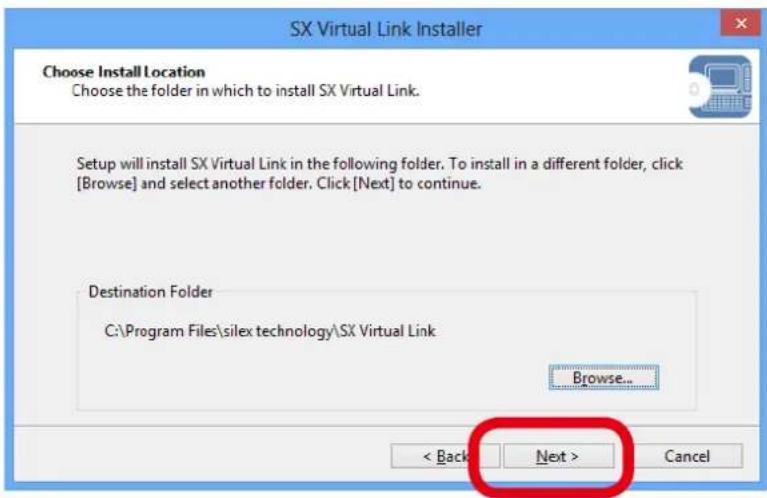
text_image
SX Virtual Link Installer Choose Install Location Choose the folder in which to install SX Virtual Link. Setup will install SX Virtual Link in the following folder. To install in a different folder, click [Browse] and select another folder. Click[Next] to continue. Destination Folder C:\Program Files\silex technology\SX Virtual Link Browse... < Back Next > Cancel
- By clicking Browse, the folder can be changed.
Note
7. Enter a group name to be displayed in the start menu and click Next.
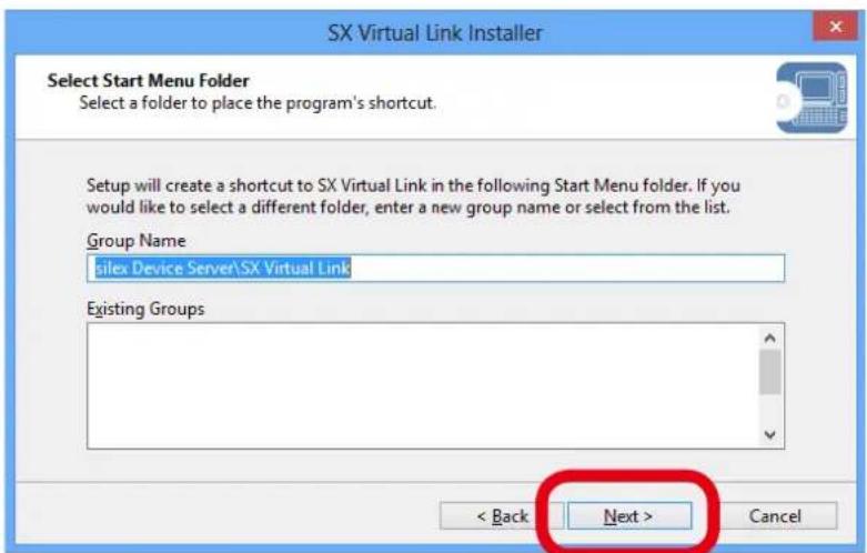
text_image
SX Virtual Link Installer Select Start Menu Folder Select a folder to place the program's shortcut. Setup will create a shortcut to SX Virtual Link in the following Start Menu folder. If you would like to select a different folder, enter a new group name or select from the list. Group Name silex Device Server\SX Virtual Link Existing Groups < Back Next > Cancel8. Click Start to begin the installation.
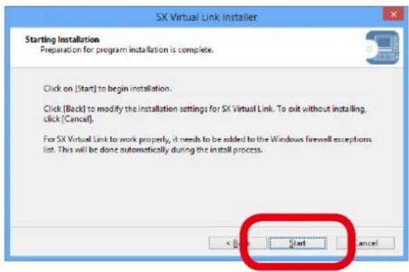
text_image
SX Virtual Link installer Starting Installation Preparation for program installation is complete. Click on [Start] to begin installation. Click [Back] to modify the installation settings for SX Virtual Link. To exit without installing, click [Cancel]. For SX Virtual Link to work properly, it needs to be added to the Windows firewall exceptions list. This will be done automatically during the install process. Start Cancel
- When Windows Security screen is displayed, click Install.
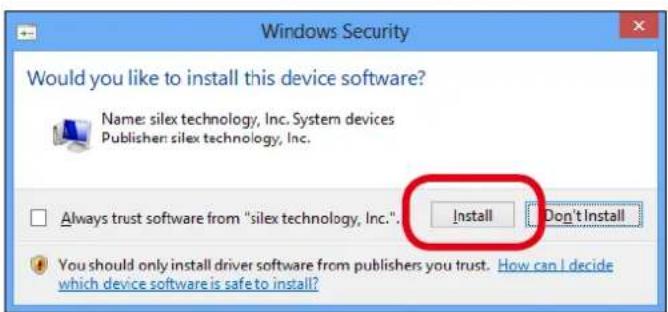
text_image
Windows Security Would you like to install this device software? Name: silex technology, Inc. System devices Publisher: silex technology, Inc. Always trust software from "silex technology, Inc.". Install Don't Install You should only install driver software from publishers you trust. How can I decide which device software is safe to install?9. SX Virtual Link has been installed. Click Finish.
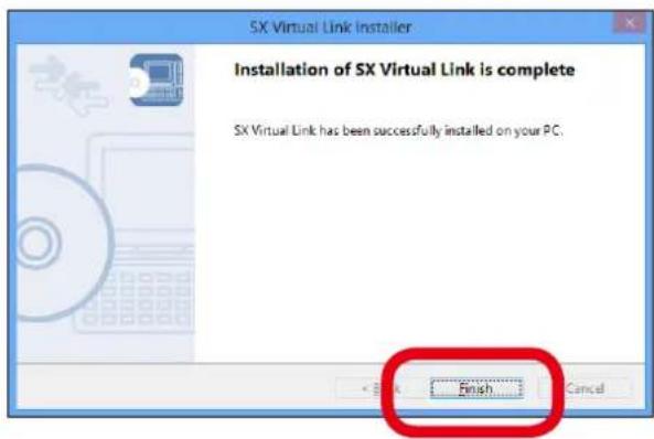
text_image
SX Virtual Link Installer Installation of SX Virtual Link is complete SX Virtual Link has been successfully installed on your PC. Finish Cancel
- If using a firewall function of commercial security software, please add SX Virtual Link to the exception list in your security software. Refer to the FAQ on our website (http://www.silexamerica.com/) for details on adding an application to the exception list.
Sharing USB Devices over the Network
How to start SX Virtual Link:
- Click the SX Virtual Link icon ( ) in the task tray.

Note
- If SX Virtual Link is not running, click Start - SX Virtual Link.
- In Windows 7, click the ( ▲ ) button on the notification area (bottom right corner of your desktop) to display the tasktray icons.
- The SX Virtual Link's main window appears. The USB devices running on a network are displayed in the device list.

text_image
SX Virtual Link SX Virtual Link AP500-123456 [84:25:3F:12:34:56 AP-500AC] USB Flash Disk Available
Note
- SX Virtual Link can be set to automatically run at startup as a minimized application in the task tray by changing the optional settings. For details on optional settings, refer to Online Help.
How to connect/disconnect to/from USB devices:
-
Select the USB device in SX Virtual Link's main window and connect to it.
-
When successfully connected to the USB device, Windows Plug and Play will run and the USB device will become ready to use.
-
When finished using the USB device, disconnect it using SX Virtual Link.
How to connect:
| Double-click Double-click the USB device in SX Virtual Link's main window. | |
| Use a button | Select the USB device and click the Connect button in SX Virtual Link's main window.If you select two or more USB devices, you can connect to them at once. |
| Right-click Right-click on the USB | device in SX Virtual Link's main window and clickConnectin the menu displayed.If you select two or more USB devices, you can connect to them at once. |
| Use a keyboard Select the USB device using the up/down arrow keys and press Alt+C on your keyboard. | |
How to disconnect:
| Double-click Double-click the USB device in SX Virtual Link's main window. | |
| Use a button | Select the USB device and click the Disconnect button in SX Virtual Link's main window. |
| Right-click Right-click on the USB device in SX Virtual Link's main window and click Disconnect in the menu displayed. | |
| Use a keyboard Select the USB device using the up/down arrow keys and press Alt+D on your keyboard. | |

- If a USB device is shared among several users, make sure that each user disconnects from the USB device after they have finished using it. Otherwise, other users will not be able to connect to the USB device.

- For details on how to use SX Virtual Link, refer to the Online Help.
Note
How to open the SX Virtual Link's Online Help
-
Start SX Virtual Link.
-
In SX Virtual Link's main window, click the Help button ( ?) and select Help from the menu displayed.
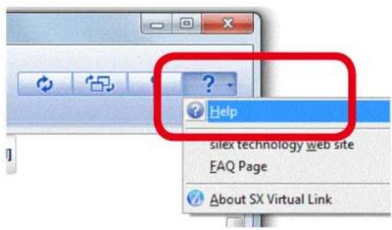
text_image
Help silex technology web site FAQ Page About SX Virtual Link- Online Help will open.
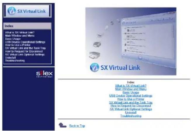
text_image
SX Virtual Link Index What is SX Virtual Link? Main Window and Menu Basic Usage USB Device Operational Settings How to Use a Printer SX Virtual Link and the Task Tray How to Request for Disconnect SX Virtual Link Optional Settings Uninstall Troubleshooting SX Virtual Link Index What is SX Virtual Link? Main Window and Menu Basic Usage USB Device Operational Settings How to Use a Printer SX Virtual Link and the Task Tray How to Request for Disconnect SX Virtual Link Optional Settings Uninstall Troubleshooting Back to TopUninstalling SX Virtual Link
How to uninstall the USB device connection utility, SX Virtual Link is explained.
Follow the procedures below to uninstall SX Virtual Link.

- To uninstall SX Virtual Link, administrator privilege is required.
1. Click Control Panel - Uninstall a program.
2. Select SX Virtual Link from the list and click Uninstall.

text_image
Control Panel Home View installed updates Turn Windows features on or off Uninstall or change a program To uninstall a program, select it from the list Organize Uninstall SX Virtual Link (1) (2)- A confirmation message is displayed. Click Yes to start the uninstallation.
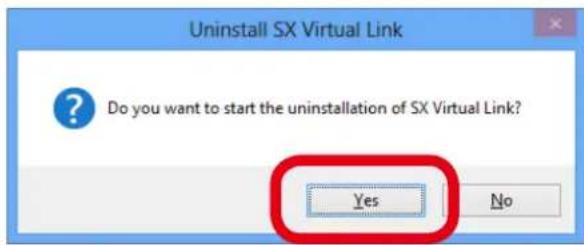
text_image
Uninstall SX Virtual Link Do you want to start the uninstallation of SX Virtual Link? Yes No- When the below window is displayed, click Finish.
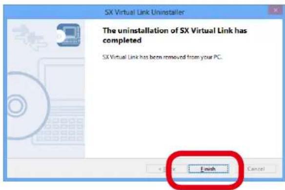
text_image
SX Virtual Link Uninstaller The uninstallation of SX Virtual Link has completed SX Virtual Link has been removed from your PC. Finish Cancel5-8. Log Output
The log information (access log, etc.) can be sent to the Syslog server as well as saved to the USB storage device connected to AP-500AC. Once the log file is saved to the USB storage device, it can be retrieved over a network using SX Virtual link. How to output the log and retrieve it from the USB storage device is explained.

- Display may vary depending on the Web browser.
- Only one USB storage device can be connected to AP-500AC to save the log to the USB storage device. Also, the connected storage device cannot be used over network using SX Virtual Link.
- When removing the USB storage device from AP-500AC, please disable the log output feature beforehand.
The log files are saved as the following formats.
| Format | ||
| Details | Date | System time when the event occurred. |
| Hostname Host name of AP-500AC | ||
| Level Message level | ||
| Program | Name of the program at which the event occurred. | |
| Message | Log message for each event- Connection of the stations- Connection/Disconnection request of the stations | |
| Output Sample | an 1 09:30:45 AP-500-0109A4 user.debug kernel: sxsyslogd: VAP-0: Connect station.(84:25:3f:01:01:01) | |
Getting Started
To retrieve the log information, the USB connection utility, SX Virtual Link is required.
For how to install, refer to 5-7. Device Server Feature.
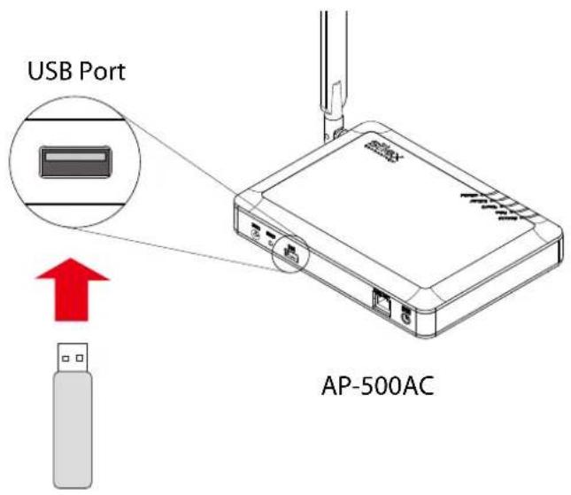
text_image
USB Port AP-500ACUSB Flash Drive
In order to save the log to USB storage device, prepare a USB storage device such as USB flash drive, etc. and connect it to AP-500AC.
Log Output Settings
- Log in to the Web page of AP-500AC using your Web browser.
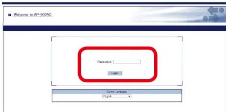
text_image
Welcome to AP-500AC Password Login Select Language English
Note
- For how to display the Web page after the initial configuration, refer to 3-2. Displaying Web Page of AP-500AC (After Initial Configuration).
- From the left menu on the Web page, click Log Output.
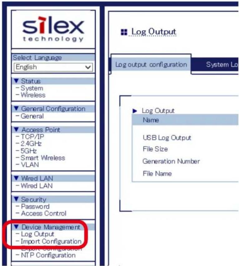
text_image
silex technology Select Language English Status - System - Wireless General Configuration - General Access Point - TCP/IP - 2.4GHz - 5GHz - Smart Wireless - VLAN Wired LAN - Wired LAN Security - Password - Access Control Device Management - Log Output - Import Configuration Export Configuration - NTP Configuration Log Output log output configuration System Lo Log Output Name USB Log Output File Size Generation Number File Name3. In the Log Output page, specify where to output the log and file names and then click Submit.
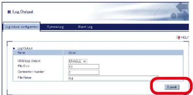
text_image
Log Output Log output configuration System Log Event Log Log Output Name Value USB Log Output ENABLE File Size 10 Generation Number 2 File Name log Submit
- For details on each configuration item, refer to A. Appendix - A-1. List of All Settings.
Note
4. When finished, click Restart.
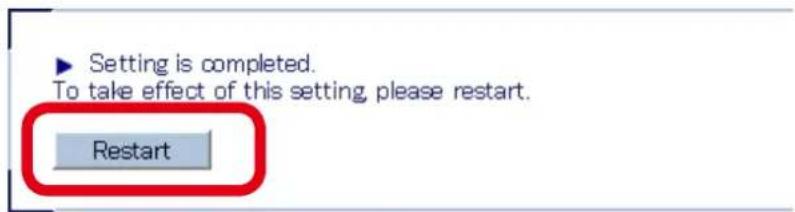
text_image
Setting is completed. To take effect of this setting, please restart. Restart
Note
- If you continue to configure the other settings, you do not have to restart. Please restart when you completed all other settings.
- The log output will not be started unless AP-500AC is restarted.
-
If the log output feature is enabled, the USB storage device connected to AP-500AC are not displayed in SX Virtual Link.
-
After the Restart button is clicked, the progress bar is displayed. When the progress bar reaches the right end, the restart is completed.

text_image
Please wait for a while until the restart is complete.Retrieving the Log Saved into USB Storage Device
To retrieve the log files saved in the USB storage device connected to AP-500AC, disable the USB log output feature first. The log can be retrieved using SX Virtual Link.
How to disable the USB log output:
- Log in to the Web page of AP-500AC using your Web browser.
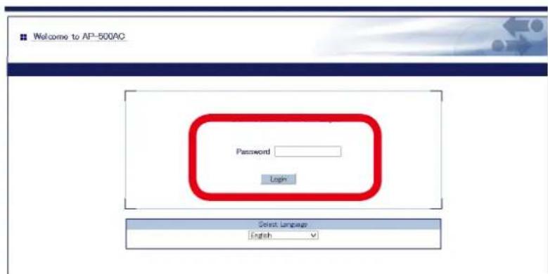
text_image
Welcome to AP-500AC Password Login Select Language English
Note
- For how to display the Web page after the initial configuration, refer to 3-2. Displaying Web Page of AP-500AC (After Initial Configuration).
2. From the left menu on the Web page, click Log Output.
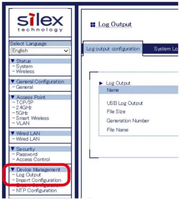
text_image
silex technology Select Language English Status - System - Wireless General Configuration - General Access Point - TCP/IP - 2.4GHz - 5GHz - Smart Wireless - VLAN Wired LAN - Wired LAN Security - Password - Access Control Device Management - Log Output - Import Configuration Export Configuration - NTP Configuration Log Output configuration System Lo Log Output Name USB Log Output File Size Generation Number File Name3. In the Log Output page, select DISABLE for USB Log Output and click Submit.
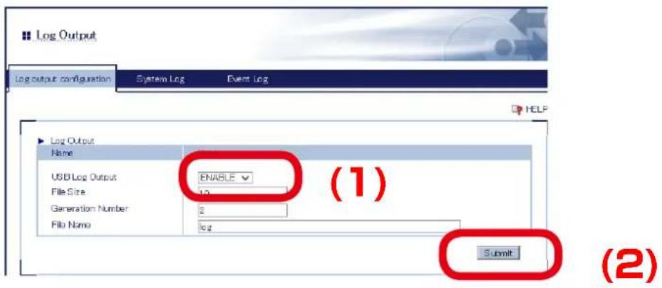
text_image
Log Output Log output configuration System Log Event Log Log Output Name USB Log Output ENABLE File Size 10 Generation Number 2 File Name log (1) Submit (2)4. When finished, click Restart.
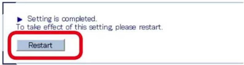
text_image
Setting is completed. To take effect of this setting, please restart. Restart
Note
- If you continue to configure the other settings, you do not have to restart. Please restart when you completed all other settings.
- The log output will not be stopped unless AP-500AC is restarted.
5. After the Restart button is clicked, the progress bar is displayed. When the progress bar reaches the right end, the restart is completed.

text_image
Please wait for a while until the restart is complete.How to retrieve the log files:
- Click the SX Virtual Link icon ( ) in the task tray.

Note
- If SX Virtual Link is not running, click Start - SX Virtual Link. - In Windows 7, click the ( ▲ ) button on the notification area (bottom right corner of your desktop) to display the tasktray icons.
- The SX Virtual Link's main window appears. The USB devices running on a network are displayed in the device list.
Select the USB storage device containing the log file and click Connect button.
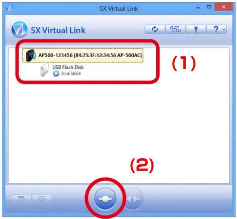
text_image
SX Virtual Link AP500-123456 [84:25:3F:12:34:56 AP-500AC] USB Flash Disk Available (1) (2)
Note
- For details on SX Virtual Link, refer to 5-7. Device Server Feature - Sharing USB Devices over the Network.
-
When successfully connected, Windows Plug and Play will run and the USB storage device will become ready to use. Now you can retrieve the saved log files.
-
When finished retrieving the log files, click Disconnect button in SX Virtual Link.
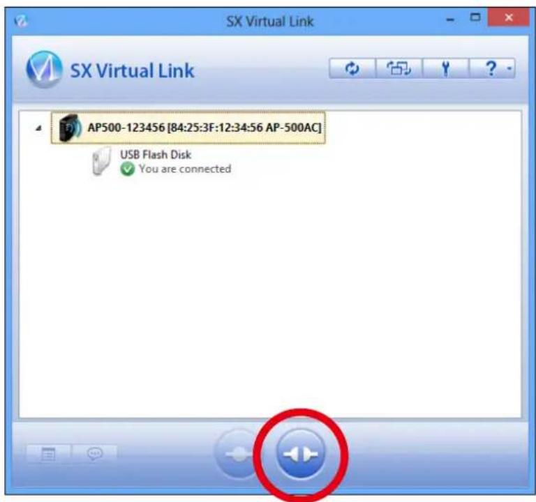
text_image
SX Virtual Link SX Virtual Link AP500-123456 [84:25:3F:12:34:56 AP-500AC] USB Flash Disk ✓ You are connected
- For details on SX Virtual Link, refer to 5-7. Device Server Feature - Sharing USB Devices over the Network.
Note
- To restart the log output, configure the log output settings again.
Notice When Using the Log Output
Please DO NOT remove the USB storage device while the USB log output is enabled.
When you remove the USB storage device, be sure to disable the USB log output feature beforehand. For how to disable the USB log output, refer to Retrieving the Log Saved into USB Storage Device - How to disable the USB log output.
If the USB storage device is removed without turning off the USB log output feature, the POWER LED on AP-500AC will blink in Red.
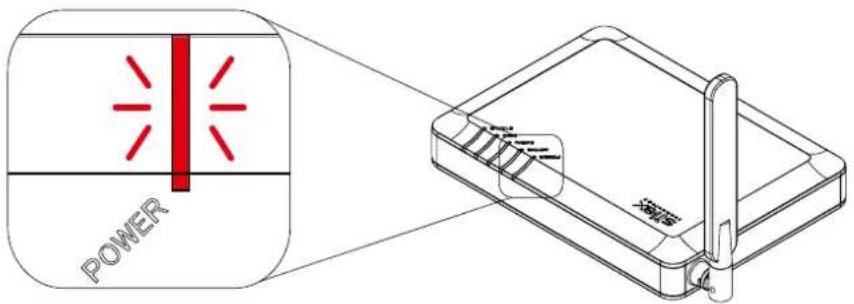
text_image
POWER 电池POWER LED : Blinks Red
AP-500AC
If the POWER LED blinks in Red, follow the instructions below to recover from it:
- Connect the removed USB storage device to the PC to verify that it has not be damaged or corrupted.

Note
- Please format the USB storage device if the data is corrupted.
-
Remove the USB storage device from the PC and reconnect it to AP-500AC.
-
Restart AP-500AC.

Note
- For how to restart AP-500AC, refer to Chapter 5-11 Maintenance Feature - Restarting.
- The log output will not be started unless AP-500AC is restarted.
5-9. Saving Log
AP-500AC can save the operating log.
Once the log is saved, it can be retrieved or deleted from the Web configuration interface.
Types of Log
There are two types of log that can be saved by AP-500AC.
System Log
Power-on status, operating status, etc. of AP-500AC are saved as a log file.
In case of a network trouble, you can check the operating status by referring the retrieved system logs.
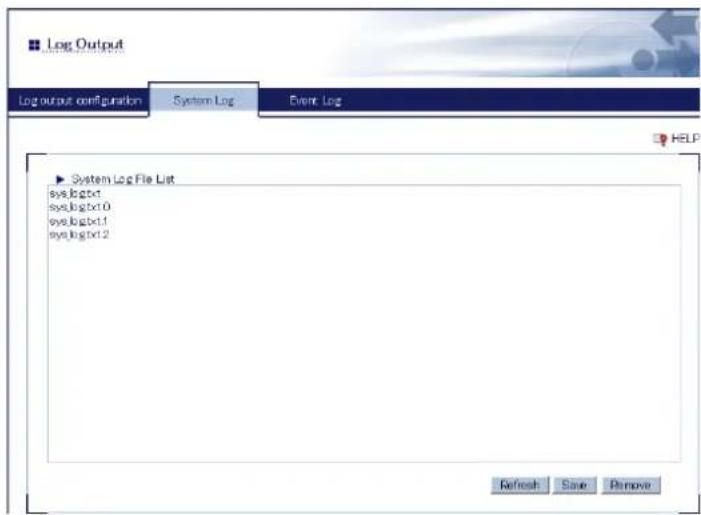
text_image
Log Output Log output configuration System Log Event Log System Log File List sys.logtxt1 sys.logtxt0 sys.logtxt1 sys.logtxt2 Refresh Save Remove
Note
- The system log file will remain even after AP-500AC is reset to factory defaults.
- When a size of log file (file name: sys_log.txt) exceeds 10MB, a new file is created. For the existing file, a number will be added to the end of the file name then.
- As the end number of the file name increases one by one when a new log file is created, files with a greater number will be older logs.
- Up to 99 log files can be saved, starting from sys_log.txt.0 to sys_log.txt.98.
- If a new file is created when 99 log files have already been there, the oldest file sys_log.txt.98 will be deleted.
• Up to 1GB log can be saved.
Event Log
When station devices are connected or disconnected, the log message is saved as a log. In case of a network trouble, you can check the wireless connection status by referring the retrieved event logs.
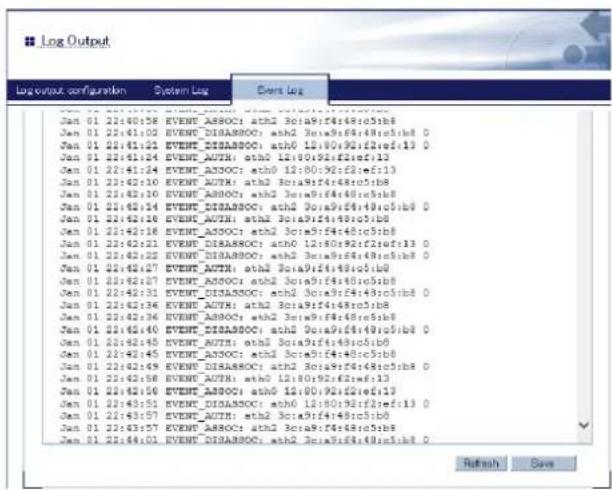
text_image
Log output configuration System Log Event Log Jan 01 21:40:58 EVENT_ASSOC: ath2 3c1a9:f4:f4:e5:b8 Jan 01 21:41:00 EVENT_DISASSOC: ath2 3c1a9:f4:f4:e5:b8 0 Jan 01 21:41:04 EVENT_AUTO: ath0 12:60:f3:f3:e1f:13 0 Jan 01 21:41:24 EVENT_AUTO: ath0 12:60:f3:f2:e1f:13 Jan 01 21:42:14 EVENT_AUTO: ath0 12:60:f3:f2:e1f:13 Jan 01 21:42:10 EVENT_AUTO: ath2 3c1a9:f4:f4:e5:b8 Jan 01 21:42:10 EVENT_AUTO: ath2 3c1a9:f4:f4:e5:b8 Jan 01 21:42:14 EVENT_DISASSOC: ath2 3c1a9:f4:f4:e5:b8 0 Jan 01 21:42:16 EVENT_AUTO: ath2 3c1a9:f4:f4:e5:b8 Jan 01 21:42:23 EVENT_DISASSOC: ath2 3c1a9:f4:f4:e5:b8 Jan 01 21:42:27 EVENT_AUTO: ath2 3c1a9:f4:f4:e5:b8 Jan 01 21:42:33 EVENT_DISASSOC: ath2 3c1a9:f4:f4:e5:b8 Jan 01 21:42:36 EVENT_AUTO: ath2 3c1a9:f4:f4:e5:b8 Jan 01 21:42:40 EVENT_DISASSOC: ath2 3c1a9:f4:f4:e5:b8 Jan 01 21:42:45 EVENT_AUTO: ath2 3c1a9:f4:f4:e5:b8 Jan 01 21:42:45 EVENT_ADDOC: ath2 3c1a9:f4:f4:e5:b8 Jan 01 21:42:49 EVENT_DISASSOC: ath2 3c1a9:f4:f4:e5:b8 Jan 01 21:42:58 EVENT_AUTO: ath0 12:60:f3:f2:e1f:13 Jan 01 21:42:56 EVENT_AUTO: ath0 12:60:f3:f2:e1f:13 Jan 01 21:43:55 EVENT_DISASSOC: ath0 12:60:f3:f2:e1f:13 Jan 01 21:43:57 EVENT_AUTO: ath2 3c1a9:f4:f4:e5:b8 Jan 01 21:43:57 EVENT_ADDOC: ath2 3c1a9:f4:f4:e5:b8 Jan 01 21:44:01 EVENT_DISASSOC: ath2 3c1a9:f4:f4:e5:b8 Refresh SaveThe event log file is saved as the format below:
| Events Log | |
| Notification of connection EVENT_AUTH: [I/F] [MACAddr] | |
| Notification of disconnection EVENT_DEAUTH: [I/F] [MACAddr] [reason code] | |
| Configuration mode start setting mode start | |
| Configuration mode error setting mode is failed | |
| Smart Wireless Setup started Smart Wireless Setting start | |
| Smart Wireless Setup finished successfully | Smart Wireless Setting Success [MACAddr] |
| Smart Wireless Setup timed out Smart Wireless Setting Timeout | |
| Smart Wireless Setup overlapped Smart Wireless Setting Overlap | |
| Smart Wireless Setup or others failed Smart Wireless Setting Failed | |
| Firmware update Firmware Update [old_version] -> [new_version] | |
| USB storage error occurred USB Storage error | |
| USB overcurrent occurred USB Overcurrent | Detect |
| Wireless module error (2.4GHz) HAL0 module is not created | |
| Wireless module error (5GHz) | HAL1 module is not created |

Note
• Only one file is saved for event log.
- Up to 64KB log information can be saved as event log file. When it exceeds 64KB, the information will automatically be deleted from the older one.
• On Web page, all log information of 64KB can be seen.

TIP
- It is impossible to delete the event log file manually.
Retrieving/Deleting System Log
How to retrieve system log:
The system log saved on AP-500AC can be accessed from the Web configuration interface.
- Log in to the Web page of AP-500AC using your Web browser.
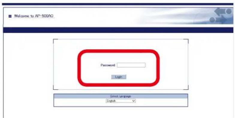
text_image
Welcome to AP-500AC Password Login Select Language English
Note
- For how to display the Web page after the initial configuration, refer to 3-2. Displaying Web Page of AP-500AC (After Initial Configuration).
- From the left menu on the Web page, click Log Output.
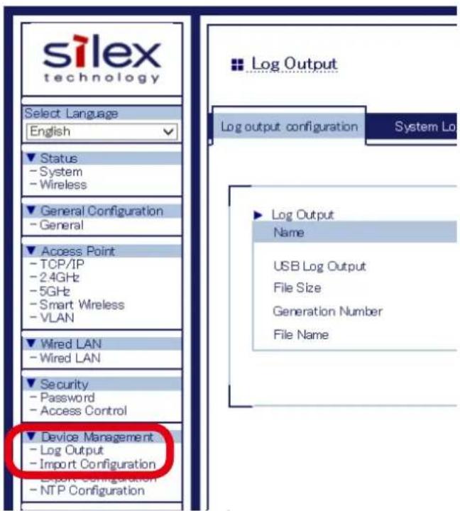
text_image
silex technology Select Language English Status - System - Wireless General Configuration - General Access Point - TCP/IP - 2.4GHz - 5GHz - Smart Wireless - VLAN Wired LAN - Wired LAN Security - Password - Access Control Device Management - Log Output - Import Configuration Export Configuration - NTP Configuration Log Output configuration System Lo Log Output Name USB Log Output File Size Generation Number File Name- Select System Log to show a list of the system logs and click Save to save them.
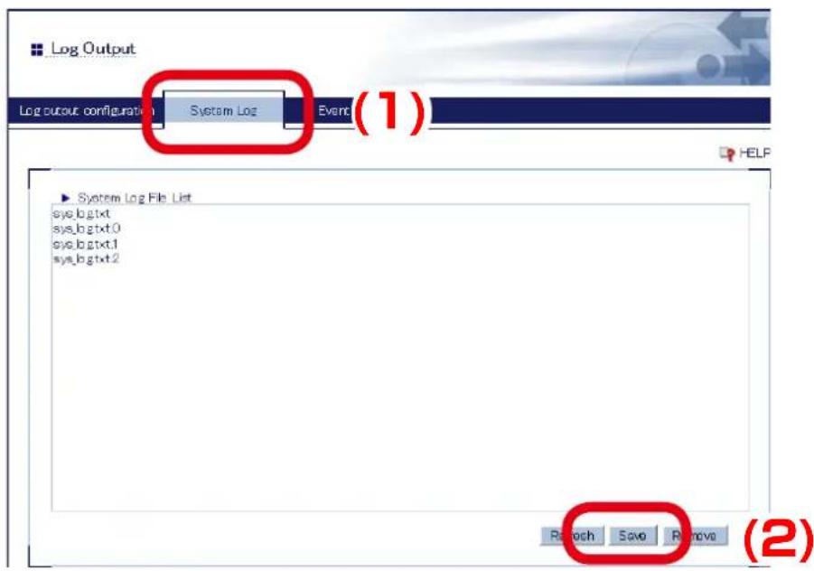
text_image
Log Output Log output configuration System Log Event (1) System Log File List sys.bgtxt sys.bgtxt0 sys.bgtxt1 sys.bgtxt2 Rach Save Remove (2)
• The log files cannot be saved individually.
- When the message appears to confirm where to save the compressed file of system logs (sys_log_archive.tgz), click Save.

text_image
Do you want to open or save sys_log_archive.tgz from 192.158.1.123? Open Save Cancel X
- If ▼ is clicked, Save as option can be selected.
Note
How to delete system log:
The system log saved on AP-500AC can be deleted from the Web configuration interface.
- Log in to the Web page of AP-500AC using your Web browser.
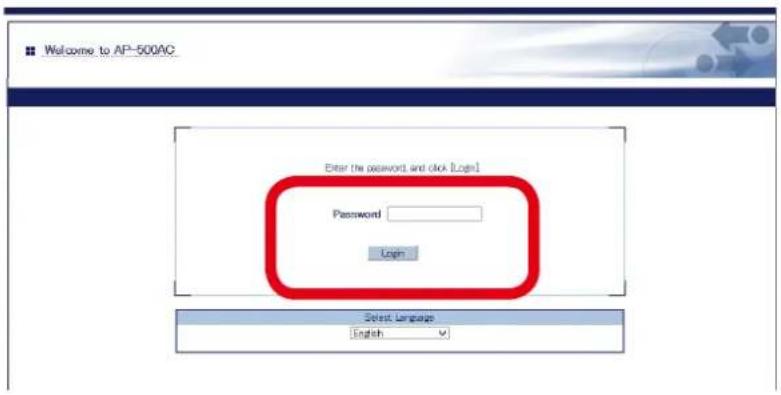
text_image
Welcome to AP-500AC Enter the password and click Login Password Login Select Language English
Note
- For how to display the Web page after the initial configuration, refer to 3-2. Displaying Web Page of AP-500AC (After Initial Configuration).
- From the left menu on the Web page, click Log Output.
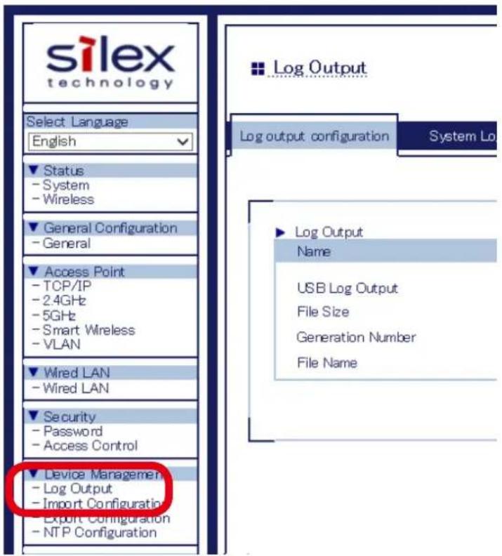
text_image
silex technology Select Language English Status - System - Wireless General Configuration - General Access Point - TCP/IP - 2.4GHz - 5GHz - Smart Wireless - VLAN Wired LAN - Wired LAN Security - Password - Access Control Device Management - Log Output - Import Configuration Export Configuration - NTP Configuration Log Output configuration System Lo Log Output Name USB Log Output File Size Generation Number File Name- Select System Log to show a list of the system logs and click Remove to delete them.
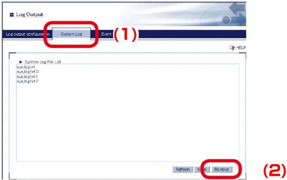
text_image
Log Output Log output configuration in System Log Event (1) System Log File List sys_bgtxt sys_bgtxt.0 sys_bgtxt.1 sys_bgtxt.2 Refresh Stop Remove (2)
• The system log files cannot be deleted individually.
- Click OK to a confirmation message.
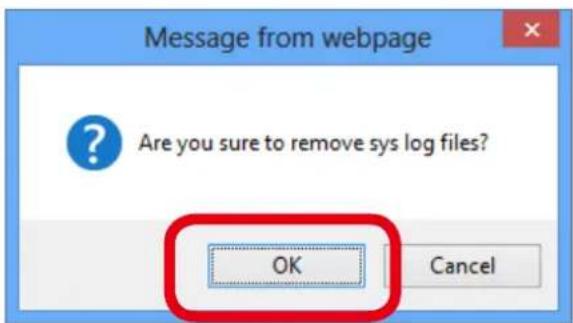
text_image
Message from webpage Are you sure to remove sys log files? OK Cancel
• If Cancel is clicked, the system log will not be deleted.
Note
Retrieving Event Log
How to retrieve the event log is explained.
The event log saved on AP-500AC can be accessed from the Web configuration interface.
- Log in to the Web page of AP-500AC using your Web browser.
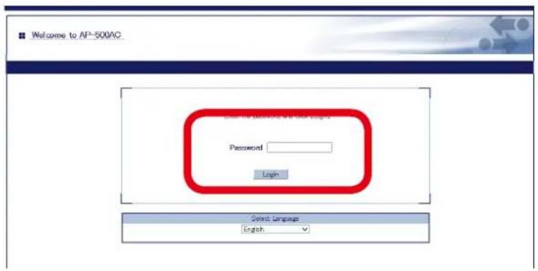
text_image
Welcome to AP-500AC Cancel Password Login Select Language English
Note
- For how to display the Web page after the initial configuration, refer to 3-2. Displaying Web Page of AP-500AC (After Initial Configuration).
- From the left menu on the Web page, click Log Output.
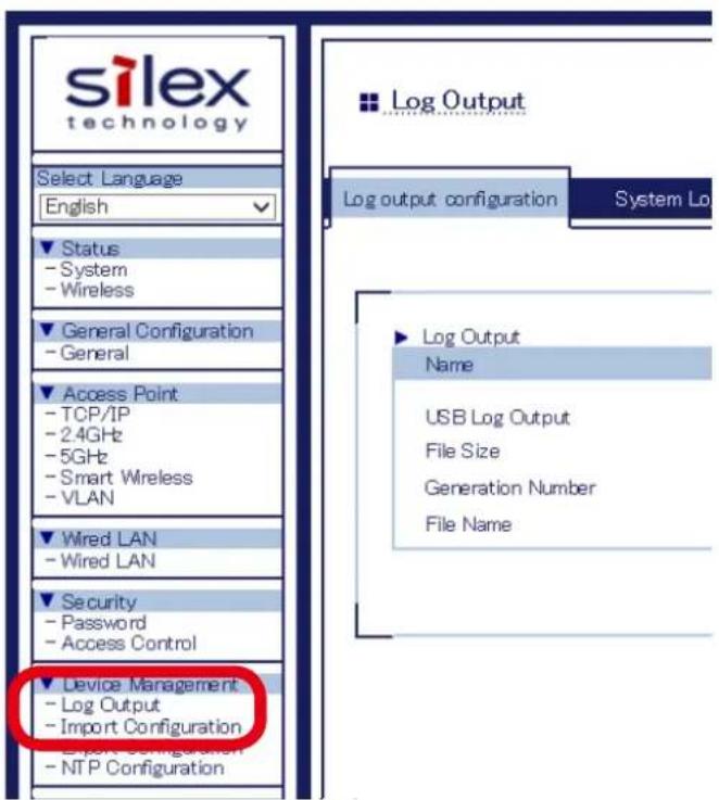
text_image
silex technology Select Language English Status - System - Wireless General Configuration - General Access Point - TCP/IP - 2.4GHz - 5GHz - Smart Wireless - VLAN Wired LAN - Wired LAN Security - Password - Access Control Device Management - Log Output - Import Configuration Export Configuration - NTP Configuration Log Output log output configuration System Lo Log Output Name USB Log Output File Size Generation Number File Name3. Click Event Log to display the event log.
Click Save to save the event log.
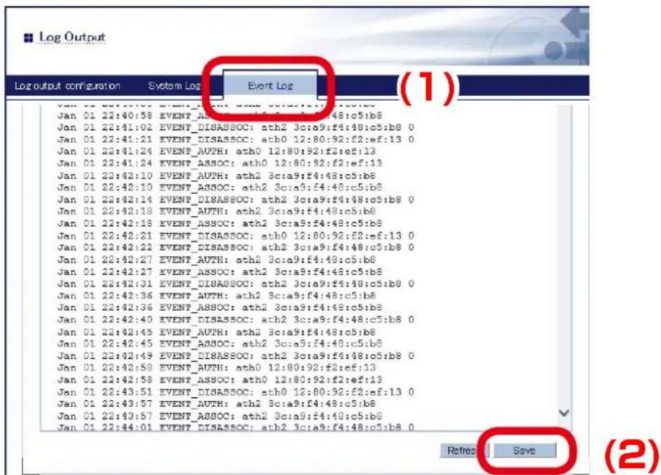
text_image
Log Output configuration System Log Event Log (1) Jan 01 22:40:58 EVENT_AUTH: ath2 3c:a9:f4:48:c5:b8 Jan 01 22:41:02 EVENT_DISASSOC: ath2 3c:a9:f4:48:c5:b8 0 Jan 01 22:41:21 EVENT_DISASSOC: ath0 12:80:92:f2:ef:13 0 Jan 01 22:41:24 EVENT_AUTH: ath0 12:80:92:f2:ef:13 Jan 01 22:41:24 EVENT_ASSOC: ath0 12:80:92:f2:ef:13 Jan 01 22:42:10 EVENT_AUTH: ath2 3c:a9:f4:48:c5:b8 Jan 01 22:42:10 EVENT_ASSOC: ath2 3c:a9:f4:48:c5:b8 Jan 01 22:42:14 EVENT_DISASSOC: ath2 3c:a9:f4:48:c5:b8 0 Jan 01 22:42:18 EVENT_AUTH: ath2 3c:a9:f4:48:c5:b8 Jan 01 22:42:18 EVENT_ASSOC: ath2 3c:a9:f4:48:c5:b8 Jan 01 22:42:21 EVENT_DISASSOC: ath0 12:80:92:f2:ef:13 0 Jan 01 22:42:22 EVENT_DISASSOC: ath2 3c:a9:f4:48:c5:b8 0 Jan 01 22:42:27 EVENT_AUTH: ath2 3c:a9:f4:48:c5:b8 Jan 01 22:42:27 EVENT_ASSOC: ath2 3c:a9:f4:48:c5:b8 Jan 01 22:42:31 EVENT_DISASSOC: ath2 3c:a9:f4:48:c5:b8 0 Jan 01 22:42:36 EVENT_AUTH: ath2 3c:a9:f4:48:c5:b8 Jan 01 22:42:36 EVENT_ASSOC: ath2 3c:a9:f4:48:c5:b8 Jan 01 22:42:40 EVENT_DISASSOC: ath2 3c:a9:f4:48:c5:b8 0 Jan 01 22:42:45 EVENT_AUTH: ath2 3c:a9:f4:48:c5:b8 Jan 01 22:42:45 EVENT_ASSOC: ath2 3c:a9:f4:48:c5:b8 Jan 01 22:42:49 EVENT_DISASSOC: ath2 3c:a9:f4:48:c5:b8 0 Jan 01 22:42:58 EVENT_AUTH: ath0 12:80:92:f2:ef:13 Jan 01 22:42:58 EVENT_ASSOC: ath0 12:80:92:f2:ef:13 Jan 01 22:43:51 EVENT_DISASSOC: ath0 12:80:92:f2:ef:13 0 Jan 01 22:43:57 EVENT_AUTH: ath2 3c:a9:f4:48:c5:b8 Jan 01 22:43:57 EVENT_ASSOC: ath2 3c:a9:f4:48:c5:b8 Jan 01 22:44:01 EVENT_DISASSOC: ath2 3c:a9:f4:48:c5:b8 0 Refresh Save (2)- When the message appears to confirm where to save the event log file, click Save.

text_image
Do you want to open or save eventlog.txt from 192.168.1.123? Open Save Cancel
- If ▼ is clicked, Save as option can be selected.
Note
5-10. Configuration Import/Export
By exporting the configuration, the current settings can be saved on to an external device. Once the configuration is saved, it can be imported back to AP-500AC anytime to restore the settings.
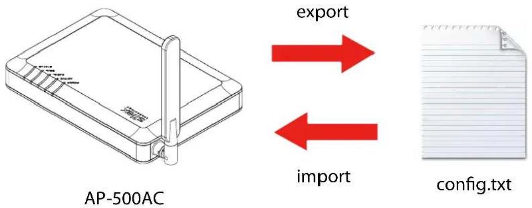
text_image
AP-500AC export import config.txt
- The configuration file you can import to AP-500AC must be the one you had exported from AP-500AC.
- After the configuration file is exported, please do not change the file name as well as edit the information. If the file is altered, you may not be able to import.
- If there are differences in firmware versions on AP-500AC between the one exporting the configuration file and the one importing the configuration file, the file may not be imported correctly.
Configuration Export
How to export configuration is explained.
- Log in to the Web page of AP-500AC using your Web browser.
text_image
Welcome to AP-500AG Enter the password and click True! Password Login Select Language English
Note
- For how to display the Web page after the initial configuration, refer to 3-2. Displaying Web Page of AP-500AC (After Initial Configuration).
- From the left menu on the Web page, click Export Configuration
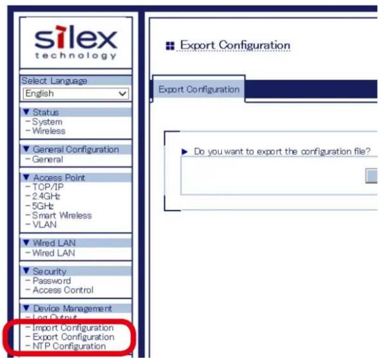
text_image
silex technology Select Language English Status - System - Wireless General Configuration - General Access Point - TCP/IP - 2.4GHz - 5GHz - Smart Wireless - VLAN Wired LAN - Wired LAN Security. - Password - Access Control Device Management - Log Output - Import Configuration - Export Configuration - NTP Configuration Export Configuration Export Configuration Do you want to export the configuration file?3. In the Export Configuration page, click Yes.
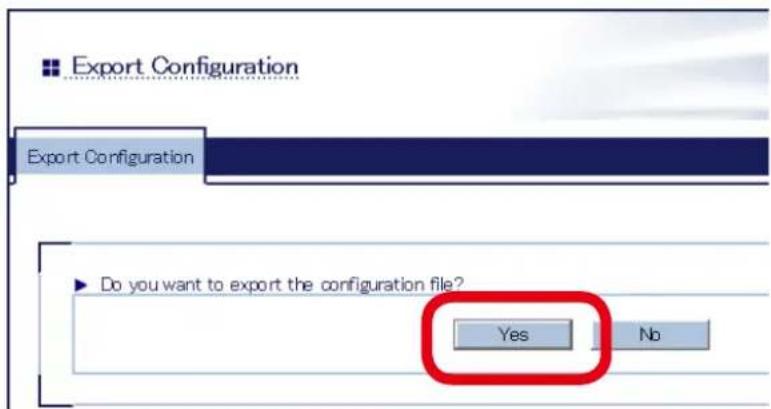
text_image
Export Configuration Export Configuration ▶ Do you want to export the configuration file? Yes No4. A message dialog to confirm where to save the configuration file (config.txt) is displayed. Click Save.

text_image
Do you want to open or save config.txt from 192.168.1.123? Open Save Cancel
- By clicking ▼you can select Save as option.
Note
Configuration Import
How to import configuration is explained.
- Log in to the Web page of AP-500AC using your Web browser.
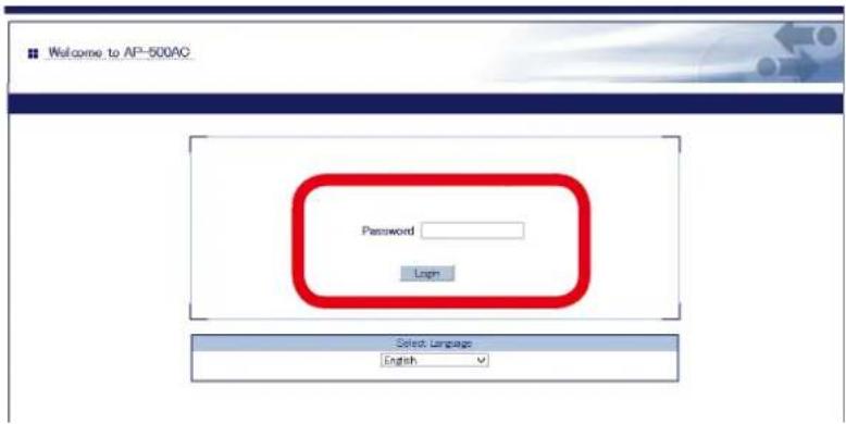
text_image
Welcome to AP-500AG Password Login Select Language English
Note
- For how to display the Web page after the initial configuration, refer to 3-2. Displaying Web Page of AP-500AC (After Initial Configuration).
- From the left menu on the Web page, click Import Configuration.
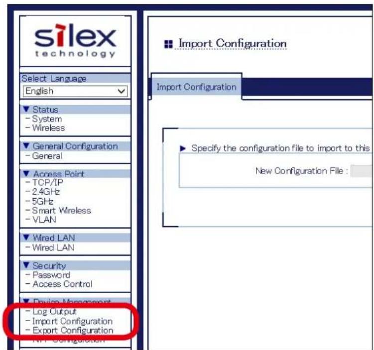
text_image
silex technology Select Language English Status - System - Wireless General Configuration - General Access Point - TCP/IP - 2.4GHz - 5GHz - Smart Wireless - VLAN Wired LAN - Wired LAN Security - Password - Access Control Device Management - Log Output - Import Configuration - Export Configuration Import Configuration Import Configuration Specify the configuration file to import to this New Configuration File :3. In the Import Configuration page, click Browse.
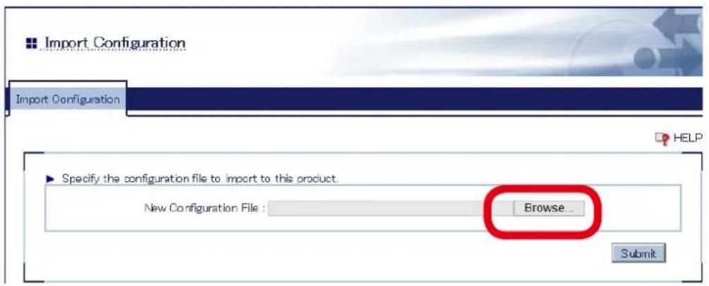
text_image
Import Configuration Import Configuration Specify the configuration file to import to this product. New Configuration File : Browse... Submit4. A window to select the configuration file (config.txt) is displayed. Select the file to upload and click Open.
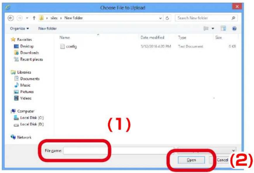
text_image
Choose File to Upload sites > New folder Organize > New folder Favorites Desktop Downloads Recent places Name config Date modified 3/12/2016:4:30 PM Type Text Document Size Libraries Documents Music Pictures Videos Computer Local Disk (C:) Local Disk (D:) Network File name: Open Cancel (1) (2)
- The configuration file you can import to AP-500AC must be the one you had exported from AP-500AC.
- In the Import Configuration page, check the configuration file you have selected is displayed at the New Configuration File field. Click Submit.
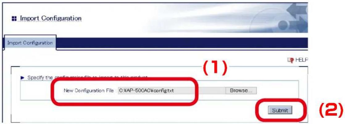
text_image
Import Configuration Import Configuration (1) Specify the configuration file to import to this product New Configuration File : C:\AP-50C\AO\config.txt Browse... Submit (2)- Click OK in a confirmation message.
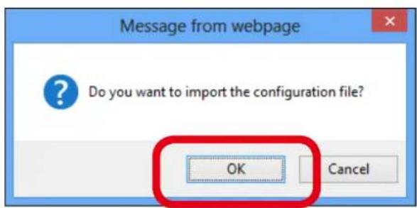
text_image
Message from webpage Do you want to import the configuration file? OK Cancel7. When finished, click Restart.
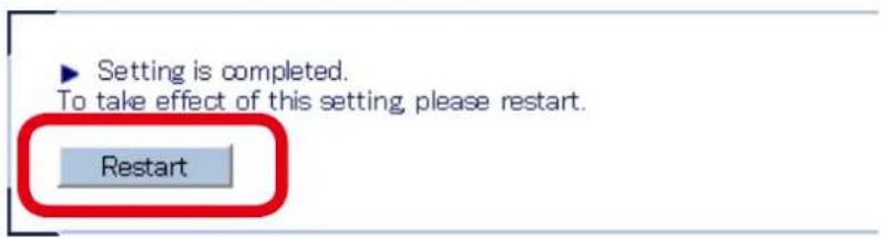
text_image
Setting is completed. To take effect of this setting, please restart. Restart- After the Restart button is clicked, the progress bar is displayed. When the progress bar reaches the right end, the restart is completed.

text_image
Please wait for a while until the restart is complete.5-11. Maintenance Feature
Restarting
How to restart AP-500AC by unplugging the AC adaptor:
- Unplug the AC adaptor of AP-500AC from the outlet.

Note
- When receiving power over the Ethernet (PoE), unplug the network cable from the HUB.
- Plug the AC adaptor back into the outlet.

Note
- When receiving power over the Ethernet (PoE), plug the network cable back into the HUB.
- When ACTIVE LED starts blinking in Green and then turns to Green, the restart is completed.
How to restart AP-500AC using the Web Page:
1. Log in to the Web page of AP-500AC using your Web browser.
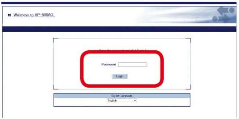
text_image
Welcome to AP-500AC Password Logh Color Language English
Note
- For how to display the Web page after the initial configuration, refer to 3-2. Displaying Web Page of AP-500AC (After Initial Configuration).
2. From the left menu on the Web page, click Maintenance - Restart.
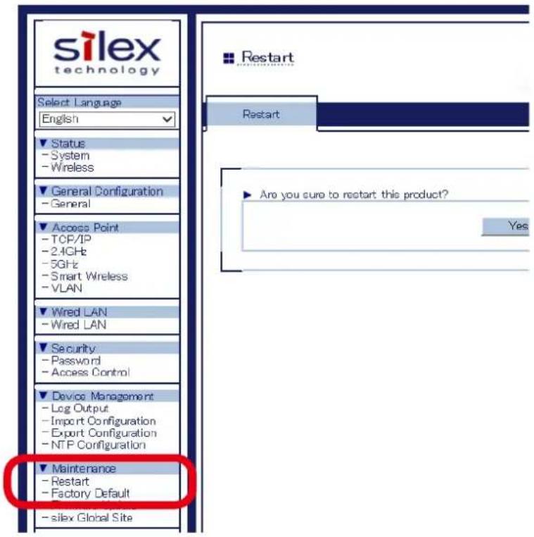
text_image
silex technology Select Language English Status - System - Wireless General Configuration - General Access Point - TCP/IP - 2.4GHz - 5GHz - Smart Wireless - VLAN Wired LAN - Wired LAN Security - Password - Access Control Device Management - Log Output - Import Configuration - Export Configuration - NTP Configuration Maintenance - Restart - Factory Default - silex Global Site Restart Are you sure to restart this product? Yes3. In the page displayed, click Yes.
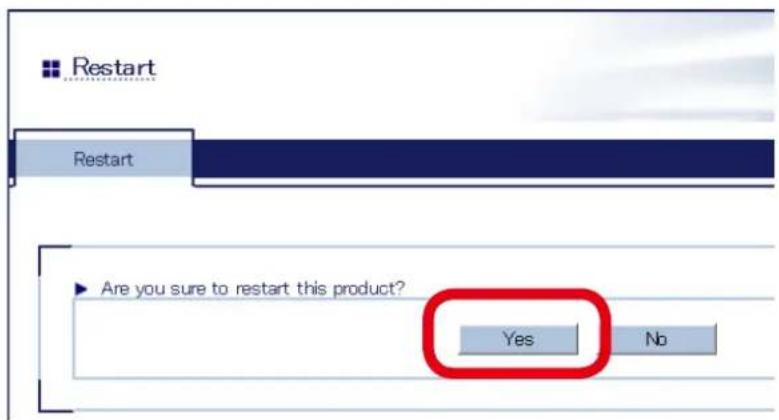
text_image
Restart Restart Are you sure to restart this product? Yes No4. After Yes is clicked, the progress bar is displayed. When the progress bar reaches the right end, the restart is completed.

text_image
Please wait for a while until the restart is complete.Factory Default Configuration
How to reset AP-500AC to factory defaults using the Push Switch:
- Unplug the AC adaptor of AP-500AC from the outlet.

Note
- When receiving power over the Ethernet (PoE), unplug the network cable from the HUB.
- Press and hold the push switch (SW2) on AP-500AC while inserting the AC plug back into the electrical outlet. Release the push switch in 2 sec or more after the Link LED and Status LED turned on.
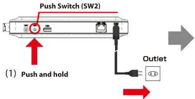
text_image
Push Switch (SW2) (1) Push and hold Outlet(2) Turn on
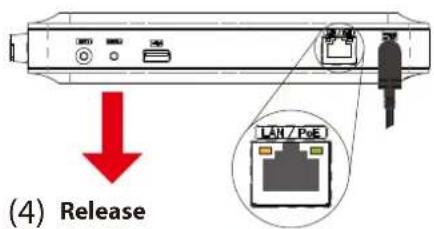
text_image
(4) Release(3) Check 2 sec is over after these LEDs turn on

Note
- When receiving power over the Ethernet (PoE), press and hold the push switch (SET1) on AP-500AC while inserting the network cable back into the HUB.
- When the factory default configuration is completed, AP-500AC is restarted automatically. When ACTIVE LED starts blinking in Green and then turns to Green, restart is completed.
How to reset AP-500AC to factory defaults using the Web page:
1. Log in to the Web page of AP-500AC using your Web browser.
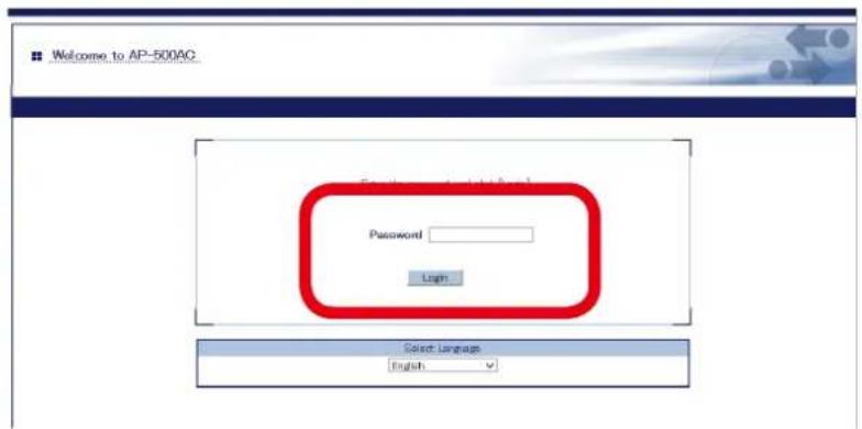
text_image
Welcome to AP-500AC Password Login Select Language English
Note
- For how to display the Web page after the initial configuration, refer to 3-2. Displaying Web Page of AP-500AC (After Initial Configuration).
2. From the left menu on the Web page, click Maintenance - Factory Default.
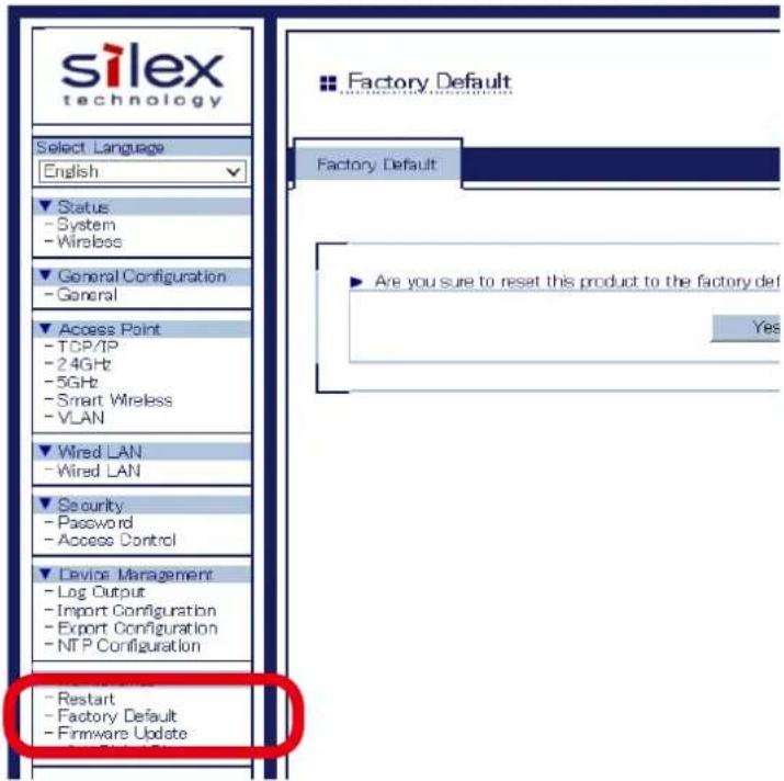
text_image
silex technology Select Language English Status - System - Wireless General Configuration - General Access Point - TCP/IP - 2.4GHz - 5GHz - Smart Wireless - VLAN Wired LAN - Wired LAN Security - Password - Access Control Device Management - Log Output - Import Configuration - Export Configuration - NTP Configuration - Restart - Factory Default - Firmware Update Factory Default Are you sure to reset this product to the factory def Yes3. In the page displayed, click Yes.
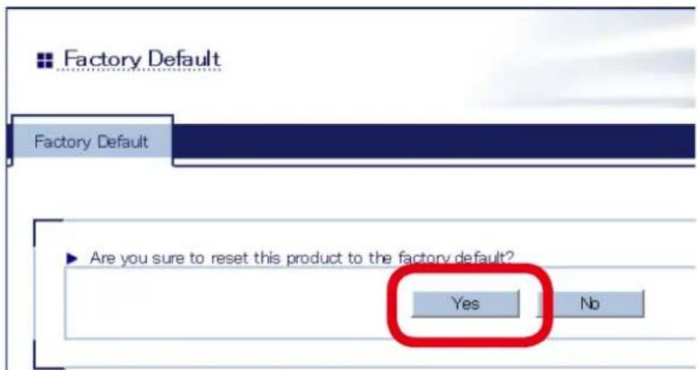
text_image
Factory Default Factory Default Are you sure to reset this product to the factory default? Yes No4. When a confirmation message is displayed, click OK.
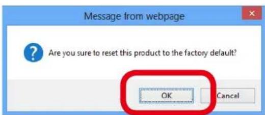
text_image
Message from webpage Are you sure to reset this product to the factory default? OK Cancel5. When the progress bar reaches the right end, the factory default configuration is completed.

text_image
Please wait for a while until the restart is complete.Firmware Update
The latest firmware file can be downloaded from our website.
See the instructions below to download the firmware file. For how to upload the firmware file to AP-500AC, refer to the firmware update procedure sheet file contained in the firmware file you download.

Note
- The current firmware version can be identified at the bottom left of the Web page.
How to download the firmware file:
- Access our website below.
| URL | |
| USA http://www.silexamerica.com/ | |
| Europe http://www.silexeurope.com/ |
- Go to the support section and download the firmware file.
5-12. Product Search Utility
How to install and use the product search utility, "AMC Finder" is explained.
Downloading & Installing the Product Search Utility
How to download the product search utility:
- Access our website below.
| URL | |
| USA http://www.silexamerica.com/ | |
| Europe http://www.silexeurope.com/ |
- Go to the support section and download AMC-Finder.
How to install the product search utility:
- Decompress the file you have downloaded and then double-click Setup.exe.
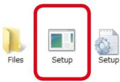
text_image
Files Setup Setup-
The User Account Control message is displayed, click Yes.
-
AMC Finder installer is started and the language selection menu is displayed. Select English and click Next.
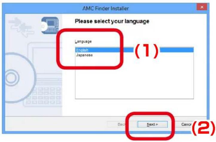
text_image
AMC Finder Installer Please select your language Language English Japanese (1) Next > Cancel (2)4. Click Next.
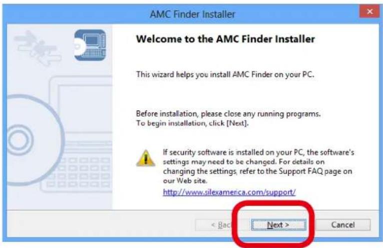
text_image
AMC Finder Installer Welcome to the AMC Finder Installer This wizard helps you install AMC Finder on your PC. Before installation, please close any running programs. To begin installation, click [Next]. If security software is installed on your PC, the software's settings may need to be changed. For details on changing the settings, refer to the Support FAQ page on our Web site. http://www.silexamerica.com/support/ < Back Next > Cancel5. Read the SOFTWARE LICENSE AGREEMENT and click Yes.
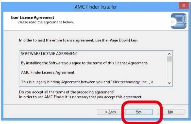
text_image
AMC Finder Installer User License Agreement Please read the agreement below. In order to read the entire license agreement, use the [Page Down] key. SOFTWARE LICENSE AGREEMENT By installing the Software you agree to the terms of this License Agreement. AMC Finder License Agreement This is a legally binding Agreement between you and "silex technology, Inc.", a Do you accept all the terms of the preceding agreement? In order to use AMC Finder it is necessary that you accept this agreement. < Back Yes No6. Select a folder to install into and click Next.
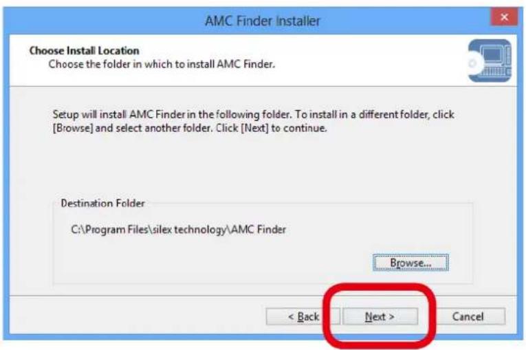
text_image
AMC Finder Installer Choose Install Location Choose the folder in which to install AMC Finder. Setup will install AMC Finder in the following folder. To install in a different folder, click [Browse] and select another folder. Click [Next] to continue. Destination Folder C:\Program Files\silex technology\AMC Finder Browse... < Back Next > Cancel
- By clicking Browse, the folder can be changed.
Note
7. Enter a group name to be displayed in the start menu and click Next.
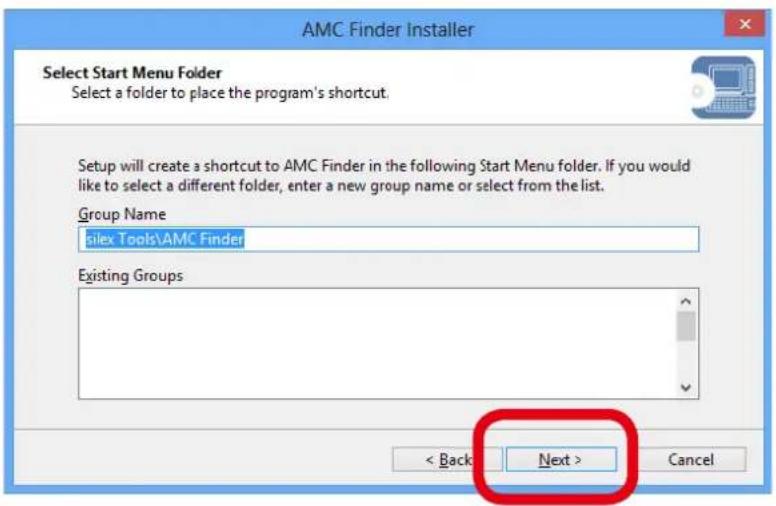
text_image
AMC Finder Installer Select Start Menu Folder Select a folder to place the program's shortcut. Setup will create a shortcut to AMC Finder in the following Start Menu folder. If you would like to select a different folder, enter a new group name or select from the list. Group Name silex Tools\AMC Finder Existing Groups < Back Next > Cancel8. Click Start to begin the installation.
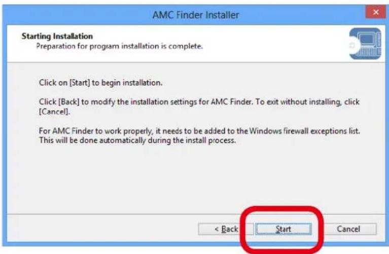
text_image
AMC Finder Installer Starting Installation Preparation for program installation is complete. Click on [Start] to begin installation. Click [Back] to modify the installation settings for AMC Finder. To exit without installing, click [Cancel]. For AMC Finder to work properly, it needs to be added to the Windows firewall exceptions list. This will be done automatically during the install process. < Back Start Cancel9. AMC Finder has been installed. Click Finish.
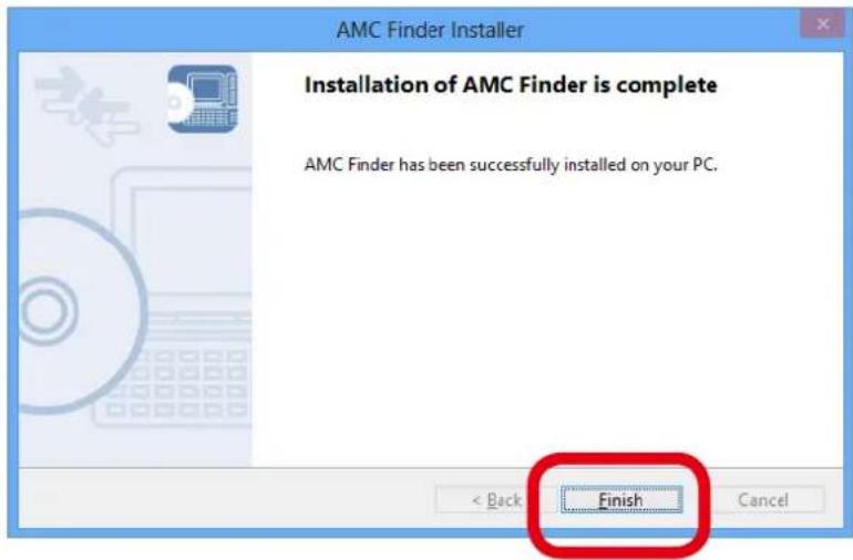
text_image
AMC Finder Installer Installation of AMC Finder is complete AMC Finder has been successfully installed on your PC. Finish < Back CancelUsing Product Search Utility
The product search utility, "AMC Finder" displays a list of AP-500AC running on a network. If AMC Finder is used, the Web page can be opened easily.

- The PC used for this configuration needs to have a proper IP address to communicate with AP-500AC. If you fail to access the Web page of AP-500AC, check the IP address of the PC first. If the IP address is not correct, configure a correct address. (Example: If the IP address of AP-500AC is "192.168.20.123", the PC must have the address such as "192.168.20.1" which is not used by other network devices.)
Following Web browsers are recommended:
- Microsoft Internet Explorer 5.5 or newer
- Firefox 2.0.0 or newer

- They may vary depending on the version of operating systems or Web browsers.
Note
How to search for AP-500AC:
Start AMC Finder. AP-500AC running on the network will be displayed.
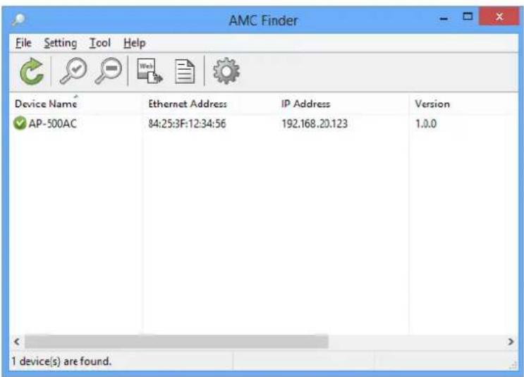
text_image
AMC Finder File Setting Tool Help Device Name Ethernet Address IP Address Version AP-500AC 84:25:3F:12:34:56 192.168..20.123 1.0.0 1 device(s) are found.
- If AP-500AC is not displayed in the list, click Refresh

Note
How to access the Web page:
1. Select AP-500AC to configure and click Configure using Web browser.
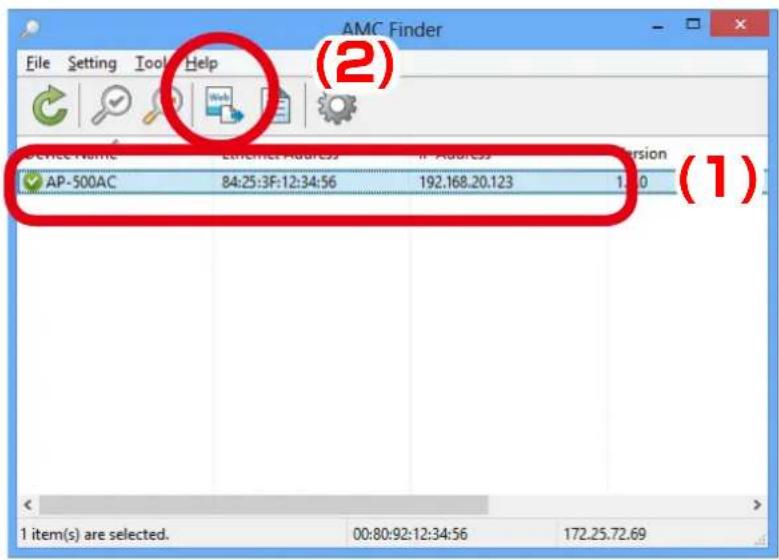
text_image
File Setting Tools Help (2) AP-500AC 84:25:3F:12:34:56 192.168.20.123 1.00 1 item(s) are selected. 00:80:92:12:34:56 172.25.72.69
Note
- If two or more of AP-500AC are displayed, select the correct one by checking the IP address and MAC address.
2. The Web browser runs and the login menu for AP-500AC is displayed. Enter the password and click Login.
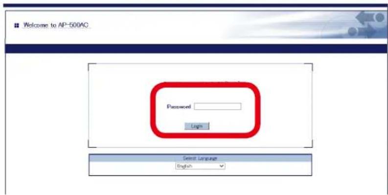
text_image
Welcome to AP-500AC Password Login Select Language English
Note
- No password is set by default. In such case, just click Login.
Uninstalling the Product Search Utility
How to uninstall the product search utility, "AMC Finder" is explained.
If AMC Finder is not necessary, you can uninstall it by following the instructions below.

TIP
- To uninstall AMC Finder, administrator privilege is required.
- Click Start - Control Panel - Uninstall a program.
- Select AMC Finder from the list and click Uninstall.
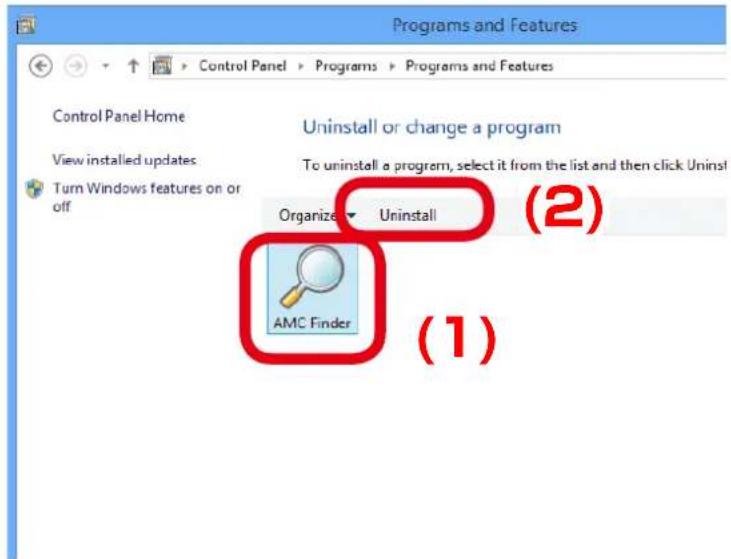
text_image
Control Panel Home View installed updates Turn Windows features on or off Uninstall or change a program To uninstall a program, select it from the list and then click Uninstall Organize Uninstall (2) (1)- A confirmation message is displayed. Click Next to start the uninstallation.
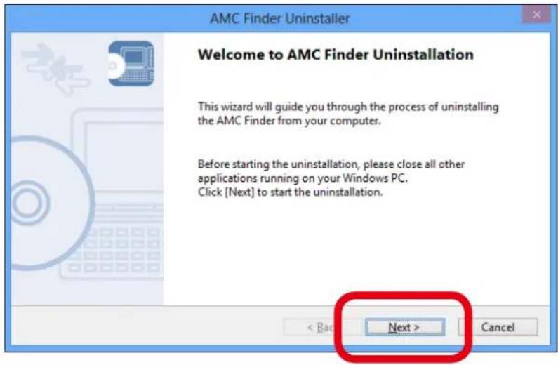
text_image
AMC Finder Uninstaller Welcome to AMC Finder Uninstallation This wizard will guide you through the process of uninstalling the AMC Finder from your computer. Before starting the uninstallation, please close all other applications running on your Windows PC. Click [Next] to start the uninstallation. < Back Next > Cancel- When the below window is displayed, click Finish.
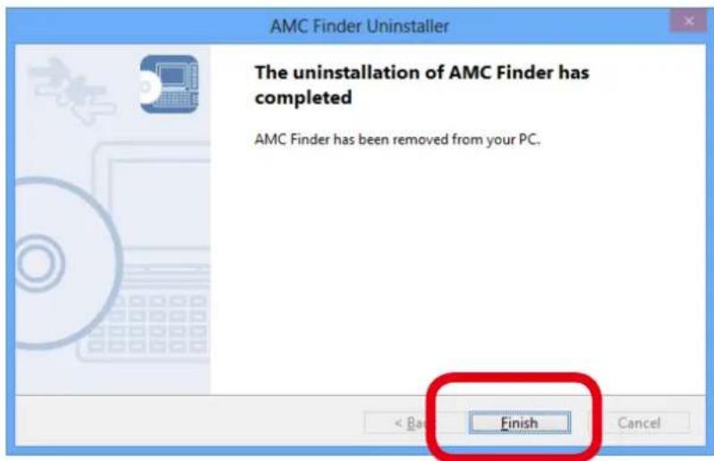
text_image
AMC Finder Uninstaller The uninstallation of AMC Finder has completed AMC Finder has been removed from your PC. Finish < Back CancelA.
Appendix
A-1. List of All Settings
This chapter explains each configuration item available on AP-500AC. Some items can be configured only from the Detail Configuration page. For details, see explanation of each configuration item below.
| General Configuration - Device Configuration | |||
| Host Name | General Configuration | * | |
| Detail Configuration | - | ||
| Details | Set the host name. Be sure to use a unique name that is not used by other devices. | ||
| Range Up to 15 characters | |||
| Default Value AP-500-xxxxxx (xxxxxx is a last 6-digit of the Ethernet Address) | |||
| TCP/IP Configuration - TCP/IP Configuration | |||
| DHCP Client | General Configuration | * | |
| Detail Configuration | * | ||
| Details Enable/Disable the DHCP protocol.To assign an IP address using DHCP, the DHCP server must be running in your subnetwork. | |||
| Range ENABLE/DISABLE | |||
| Default Value DISABLE | |||
| IP Address | General Configuration | * | |
| Detail Configuration | * | ||
| Details Set the IP address.When DHCP client is enabled, the IP Address obtained from DHCP server will be applied. | |||
| Range 0.0.0.0 - 255.255.255.255.255 | |||
| Default Value The default value can be found on the product label (see the bottom of the unit). | |||
| Subnet Mask | General Configuration | * | |
| Detail Configuration | * | ||
| Details Set the subnet mask.When DHCP client is enabled, the Subnet Mask obtained from DHCP server will be applied. | |||
| Range 0.0.0.0 - 255.255.255.255.255.255.255.255.255.255.255.255.255.255.255.255.255.255.255.255.255.255.255.255.255.255 | |||
| Note When set to "0.0.0.0", a subnet mask appropriate for the IP address is automatically assigned. | |||
| Default Gateway | General Configuration | * | |
| Detail Configuration | * | ||
| Details | Set the gateway address.If "0.0.0.0" is set, this setting is disabled. When DHCP client is enabled, the Default Gateway obtained from DHCP server will be applied. | ||
| Range 0.0.0.0 - 255.255.255.255.255.255.255.255.255.255.255.255.255.255.255.255.255.255.255.255.255 | |||
| Default Value 0.0.0.0 | |||
| TCP/IP Configuration - DNS Configuration | |||
| DNS Server (Primary) | General Configuration | - | |
| Detail Configuration | * | ||
| Details Set a primary | DNS server address.When DHCP client is enabled, the DNS server address obtained from DHCP server will be applied. | ||
| Range | 0.0.0.0 - 255.255.255.255 | ||
| Default Value 0.0.0.0 | |||
| DNS Server (Secondary) | General Configuration | - | |
| Detail Configuration | * | ||
| Details Set a secondary DNS server address.When DHCP client is enabled, the DNS server address obtained from DHCP server will be applied. | |||
| Range | 0.0.0.0 - 255.255.255.255 | ||
| Default Value 0.0.0.0 | |||
| TCP/IP Configuration - DHCP Server Configuration | |||
| DHCP Server Function | General Configuration | * | |
| Detail Configuration | * | ||
| Details Enable/Disable the DHCP server function.Select ENABLE to run AP-500AC as a DHCP server to automatically assign an IP address to the PC.Select DISABLE if you already have a DHCP server on the network. | |||
| Range ENABLE/DISABLE | |||
| Default Value DISABLE | |||
| Start IP Address | General Configuration | * | |
| Detail Configuration | * | ||
| Details Set the start IP address used for DHCP server function to assign the address.The value must be 4 numbers separated by dots and expressed in the format [xxx.xxx.xxx.xxx]. | |||
| Range 0.0.0.0 - 255.255.255.255 | |||
| Default Value 0.0.0.0 | |||
| End IP Address | General Configuration | * | |
| Detail Configuration | * | ||
| Details Set the end IP address used for DHCP server function to assign the address.The value must be 4 numbers separated by dots and expressed in the format [xxx.xxx.xxx.xxx]. | |||
| Range 0.0.0.0 - 255.255.255.255 | |||
| Default Value 0.0.0.0 | |||
| Subnet Mask | General Configuration | * | |
| Detail Configuration | * | ||
| Details Set the subnet mask for IP addresses to be assigned.The value must be 4 numbers separated by dots and expressed in the format [xxx.xxx.xxx.xxx]. | |||
| Range 0.0.0.0 - 255.255.255.255 | |||
| Default Value 0.0.0.0 | |||
| Note | When set to "0.0.0.0", this setting is disabled and a subnet mask appropriate for the start IP address is automatically used. | ||
| Default Gateway | General Configuration | * | |
| Detail Configuration | * | ||
| Details Set the gateway address.The value must be 4 numbers separated by dots and expressed in the format [xxx.xxx.xxx.xxx]. | |||
| Range 0.0.0.0 - 255.255.255.255 | |||
| Default Value 0.0.0.0 | |||
| Note When set to "0.0.0.0", this setting is disabled and default gateway address is not assigned by DHCP. | |||
| Lease Time | General Configuration | * | |
| Detail Configuration | * | ||
| Details Set the lease time.If this is set to 0 days + 0 hours + 0 mins, the lease period will be 10 days. | |||
| Range 0 days 0 hours 0 mins - 44 days 23 hours 59 mins | |||
| Default Value 0 days 0 hours 0 mins | |||
| DNS Server | General Configuration | * | |
| Detail Configuration | * | ||
| Details Set the DNS server address.The value must be 4 numbers separated by dots and expressed in the format [xxx.xxx.xxx.xxx]. | |||
| Range 0.0.0.0 - 255.255.255.255 | |||
| Default Value 0.0.0.0 | |||
| Wireless LAN Configuration (2.4GHz) - Wireless LAN Common Configuration | |||
| Wireless Mode | General Configuration | * | |
| Detail Configuration | * | ||
| Details Select the IEEE 802.11wireless mode. | |||
| Range 802.11b, 802.11b/g, 802.11n/b/g | |||
| Default Value 802.11n/b/g | |||
| Note 802.11b: Uses IEEE802.11b.802.11b/g: Uses IEEE802.11b or IEEE802.11g.802.11n/b/g: Uses IEEE802.11n, IEEE802.11b or IEEE802.11g. | |||
| Channel Bandwidth | General Configuration | * | |
| Detail Configuration | * | ||
| Details Set the frequency bandwidth.This setting is necessary when using 802.11n/b/g.In a wireless network, bandwidth is divided up so that more devices can communicate at a time. Each section of bandwidth is called a ' channel ' and each channel has a bandwidth of 20MHz. If 40MHz is selected, larger and faster data transmission can be realized. | |||
| Range 20MHz/40MHz | |||
| Default Value 20MHz | |||
| Note 40MHz (High speed): Uses double bandwidth. Two neighboring bandwidths are combined together for high speed transmission.20MHz (Standard): Uses standard (single) bandwidth.If your network becomes unstable when using 40MHz, change it to 20MHz (Standard). | |||
| Channel | General Configuration | * | |
| Detail Configuration | * | ||
| Details Set the wireless channel.A channel is the divided frequency bandwidth. In a wireless network, bandwidth is divided up so that more devices can communicate at a time. | |||
| Range (Japan) 1-13/AUTO(US/Canada) 1-11/AUTO(EU) 1-13/AUTO | |||
| Default Value 11 | |||
| Note If your network becomes unstable due to interference with other wireless devices, it could be improved by changing the channel. The channel you can use will differ depending on the country. | |||
| Ext Channel | General Configuration | * | |
| Detail Configuration | * | ||
| Details Set the extended channel when 40MHz is selected for channel bandwidth.Available extended channels will differ depending on the channel. | |||
| Range 1-13 | |||
| Default Value Depending on the channel | |||
| Wireless LAN Configuration (2.4GHz) - Wireless LAN Basic Configuration 1/2 | |||
| Interface | General Configuration | * | |
| Detail Configuration | * | ||
| Details Enable/Disable the wireless LAN interface 1-2. | |||
| Range ENABLE/DISABLE | |||
| Default Value Wireless LAN1: ENABLE, Wireless LAN2: DISABLE | |||
| SSID | General Configuration | * | |
| Detail Configuration | * | ||
| Details Set the SSID of the wireless network.The SSID is an ID that distinguishes a wireless LAN network from others. For wireless devices to communicate with each other on a wireless network, they must share the same SSID. | |||
| Range Up to 32 characters | |||
| Default Value Wireless LAN1: AP-500-xxxxxx-1Wireless LAN2: AP-500-xxxxxx-2(xxxxxx is the last 6 digits of the Ethernet Address) | |||
| Stealth Mode | General Configuration | * | |
| Detail Configuration | * | ||
| Details Enable/Disable the Stealth Mode. | |||
| Range ENABLE/DISABLE | |||
| Default Value DISABLE | |||
| Note If the Stealth Mode is enabled, the Smart Wireless Setup feature can no longer be used. | |||
| Network Authentication | General Configuration | ||
| Detail Configuration | |||
| Details Select the network authentication mode that will be used to connect to your wireless devices.To ensure a secure network, it is recommended to use WPA/WPA2. When IEEE 802.11n is used or when WPA2 is used as authentication method, TKIP encryption cannot be used. | |||
| Range | Open, Shared, WPA-PSK, WPA2-PSK, WPA/WPA2-PSK, 802.1X, WPA-Enterprise, WPA2-Enterprise, WPA/WPA2-Enterprise | ||
| Default Value Wireless LAN1: WPA2-PSKWireless LAN2: Open | |||
| Note Open (Open System):Allows all access without authentication. For encryption mode, WEP can be used.Shared (Pre-Shared Key):Uses WEP key for encryption and allows access only from those with the same WEP key. For encryption mode, WEP can be used.WPA-PSK:Uses PSK for network authentication. For encryption mode, TKIP/AES/AUTO can be selected. The encryption key will be generated by communicating with your wireless devices using a Pre-Shared key. WEP key setting is not used for this mode.WPA2-PSK:Uses PSK for network authentication. For encryption mode, AES/AUTO can be selected. The encryption key will be generated by communicating with your wireless devices using a Pre-Shared key. WEP key setting is not used for this mode.WPA/WPA2-PSK:Uses both WPA-PSK and WPA2-PSK authentication.802.1X:Uses IEEE 802.1X user authentication and WEP encryption.WPA-Enterprise:Uses IEEE 802.1X user authentication and TKIP/AES/AUTO encryption.WPA2-Enterprise:Uses IEEE 802.1X user authentication and AES/AUTO encryption.WPA/WPA2-Enterprise:Uses IEEE 802.1X user authentication and AES/AUTO encryption.When running in IEEE 802.11n, Shared and IEEE 802.1X authentication modes and WEP and TKIP encryption modes cannot be used. | |||
| Wireless LAN Configuration (2.4GHz) - WEP Configuration | |||
| WEP | General Configuration | * | |
| Detail Configuration | * | ||
| Details Enable/Disable WEP encryption.If WEP encryption is used, wireless communication will be encrypted using the settings of WEP Key 1-4 and Key Index. | |||
| Range ON/OFF | |||
| Default Value OFF | |||
| Note If encryption is not enabled, data is not encrypted and is sent as is. To ensure higher security, enabling encryption is recommended. | |||
| Key Index | General Configuration | * | |
| Detail Configuration | * | ||
| Details Select the number of the WEP key to use for encryption (1-4).This setting must be the same as that of your wireless devices. | |||
| Range 1 - 4 | |||
| Default Value 1 | |||
| WEP Key1-4 | General Configuration | * | |
| Detail Configuration | * | ||
| Details Set the WEP key for WEP encryption.Up to 4 WEP keys can be set. This setting must be the same as that of your wireless devices. A WEP key must be entered using hexadecimal or alphanumeric characters. | |||
| Range 5 or 13 characters10 or 26 digit value | |||
| Default Value (None) | |||
| Note In most cases, alphanumeric characters are used.Enter 5 characters if the key size is 64bit or 13 characters if the key size is 128bit.For Hexadecimal, a value consists of numbers (0-9) and English letters (A-F). Enter a 10-digit value if the key size is 64bit or a 26-digit value if the key size is 128bit. | |||
| Wireless LAN Configuration (2.4GHz) - WPA/WPA2 Configuration | |||
| Encryption Mode | General Configuration | * | |
| Detail Configuration | * | ||
| Details | Select the encryption mode to use for WPA-PSK, WPA2-PSK, WPA/WPA2-PSK, WPA-Enterprise, WPA2-Enterprise, WPA/WPA2-Enterprise authentication. | ||
| Range TKIP/AES/AUTO | |||
| Default Value AES | |||
| Note | When the network authentication mode is WPA2-PSK, WPA/WPA2-PSK, WPA2-Enterprise, WPA/WPA2-Enterprise, TKIP cannot be used.* The max number of connectable station devices will differ depending on the encryption mode used.- When using AES only: 100 units- When using TKIP or AUTO: 50 units* In Multi SSID environment, the number of connected devices will be the total number of devices connected on all wireless interfaces. Thus, the max number of connectable devices will differ depending on the encryption mode used on each interface.- When all wireless interfaces use AES only: 100 units- When one or some of the wireless interfaces use TKIP or AUTO: 50 units* When using the WDS feature, the Repeater AP connected to AP-500AC as client AP will consume one connection, while Root AP or Repeater APs connected to AP-500AC as host AP will NOT consume any connections. | ||
| Pre-Shared Key | General Configuration | * | |
| Detail Configuration | * | ||
| Details Set the Pre-Shared Key to use for TKIP/AES encryption.The Pre-Shared Key is a keyword used to create the encryption key. It is also referred to as 'network key' or 'password'. | |||
| Range 8-63 alphanumeric characters64 hexadecimal value | |||
| Default Value Wireless LAN1: xxxxxxxxWireless LAN2: xxxxxxxx(xxxxxxxxx is the sequence of numbers generated by a particular rule based on the Ethernet Address.)* The default value can be found on the product label (see the bottom of the unit). | |||
| Note In most case, alphanumeric characters are used (8-63 characters).For Hexadecimal, a value consists of numbers (0-9) and English letters (A-F).* This setting must be the same as that of your wireless devices. | |||
| Group key renew interval | General Configuration | * | |
| Detail Configuration | * | ||
| Details Set the refresh interval for Pre-Shared Key (min).If 0 is set, this setting is disabled. | |||
| Range 0 - 1440 | |||
| Default Value 60 | |||
| Wireless LAN Configuration (2.4GHz) - RADIUS Server Configuration | |||
| Server IP | General Configuration | * | |
| Detail Configuration | * | ||
| Details Set the IP Address of RADIUS server.This needs to be set only when the network authentication is 802.1X, WPA-Enterprise, WPA2-Enterprise or WPA/WPA2-Enterprise. | |||
| Range 0.0.0.0 - 255.255.255.255 | |||
| Default Value 0.0.0.0 | |||
| Port Number | General Configuration | * | |
| Detail Configuration | * | ||
| Details Set the port number used to communicate with RADIUS server. | |||
| Range 0 - 65535 | |||
| Default Value 1812 | |||
| Shared Secret | General Configuration | * | |
| Detail Configuration | * | ||
| Details Set the secret key used to communicate with RADIUS server. | |||
| Range Up to 64 characters | |||
| Default Value (None) | |||
| Wireless LAN Configuration (2.4GHz) - WDS Configuration | |||
| WDS Mode | General Configuration | * | |
| Detail Configuration | * | ||
| Details Set the WDS operation mode to make communication between the Access Points.The WDS network consists of one Root AP (host) and plural Repeater APs (client). | |||
| Range DISABLE/Root AP/Repeater | |||
| Default Value DISABLE | |||
| Note DISABLE: | Does not use WDS.RootAP:Runs as Root AP for WDS.This exchanges traffic among Repeater, wired LAN and wireless client device.Repeater:Runs as Repeater for WDS.This exchanges traffic among Root AP, Repeater, wired LAN and wireless client device by connecting to Root AP or Repeater. | ||
| Wireless LAN Interface | General Configuration | * | |
| Detail Configuration | * | ||
| Details Select the wireless interface for WDS to make communication between the Access Points. | |||
| Range Wireless1 / Wireless2 | |||
| Default Value Wireless1 | |||
| Note The MAC Address displayed under the Wireless Interface is the MAC Address of AP-500AC to use for WDS. This information will be used on Repeater AP which sets AP-500AC as a host AP. | |||
| Access Point MAC Address | General Configuration | * | |
| Detail Configuration | * | ||
| Details Set the MAC Address for Root AP or Repeater AP to connect as host AP in WDS mode. | |||
| Range 00:00:00:00:00 - FF:FF:FF:FF:FF:FF | |||
| Default Value 00:00:00:00:00:00:00:00 | |||
| Note This setting is not necessary on Root AP.The MAC Address for Root AP or Repeater AP to connect as a host AP in WDS can be seen on the Web page of the host AP. Log in to the Web page of the host AP and click 2.4GHz - WDS Configuration - Wireless LAN Interface. The MAC Address will be displayed under the Wireless LAN Interface. | |||
| Wireless LAN Configuration (2.4GHz) - Extension Configuration | |||
| Beacon Interval(msec) | General Configuration | - | |
| Detail Configuration | * | ||
| Details Set the beacon transmission interval (millisec). | |||
| Range 20 - 1000 | |||
| Default Value 100 | |||
| DTIM | General Configuration | - | |
| Detail Configuration | * | ||
| Details Set the DTIM interval for a wireless LAN. | |||
| Range 1 - 255 | |||
| Default Value 1 | |||
| Transmit Power(%) | General Configuration | - | |
| Detail Configuration | * | ||
| Details Set the transmission strength level.When a lower strength level is selected, the radio transmission distance is shortened and the scope of search for AP-500AC will be narrowed down. By narrowing down the scope of search, the risk of interference to the other wireless networks could be reduced. | |||
| Range 5 - 100 | |||
| Default Value 100 | |||
| RTS Threshold | General Configuration | - | |
| Detail Configuration | * | ||
| Details Set the RTS threshold value. | |||
| Range 1 - 2346 | |||
| Default Value 2346 | |||
| Short Preamble | General Configuration | - | |
| Detail Configuration | * | ||
| Details Enable/Disable the Short Preamble (ON/OFF). | |||
| Range ON/OFF | |||
| Default Value ON | |||
| Note This can be set only when the Wireless Mode is 802.11b or 802.11b/g. | |||
| A-MPDU | General Configuration | - | |
| Detail Configuration | * | ||
| Details Enable/Disable the A-MPDU (ON/OFF).If this is enabled (ON), higher throughput could be achieved. | |||
| Range ON/OFF | |||
| Default Value ON | |||
| Note This can be set only when the Wireless Mode is 802.11n/b/g. | |||
| Short Guard Interval | General Configuration | - | |
| Detail Configuration | * | ||
| Details Enable/Disable the Short Guard Interval (ON/OFF).If this is enabled (ON), higher throughput could be achieved. | |||
| Range ON/OFF | |||
| Default Value ON | |||
| Note This can be set only when all of the following conditions are met:- Wireless Mode is set to 802.11n/b/g- Channel bandwidth is set to 40MHz. | |||
Wireless LAN Configuration (2.4GHz) - QoS(WMM) Configuration (for AP)
| BE | General Configuration | - | |
| Detail Configuration | * | ||
| Details Change the Q | oS setting for BE(Best Effort) of WMM-EDCA. | ||
| Range ECWmin: 1 - 15 | |||
| ECWmax:1 - 15AIFSN:1 - 15TxOPLimit: 0 - 8192 | |||
| Default Value ECWmin: 4 | |||
| ECWmax: 6AIFSN: 3TxOPLimit: 0 | |||
| Note TxOPLimit must be a multiple of 32. When the entered value is not a multiple of 32, a largest multiple number of 32 not exceeding the entered value will be applied. | |||
| BK | General Configuration | - | |
| Detail Configuration | * | ||
| Details Change the Q | oS setting for (BK: Back Ground) of WMM-EDCA. | ||
| Range ECWmin: 1 - 15 | |||
| ECWmax: 1 - 15AIFSN: 1 - 15TxOPLimit: 0 - 8192 | |||
| Default Value ECWmin: 4 | |||
| ECWmax: 10AIFSN: 7TxOPLimit: 0 | |||
| Note TxOPLimit must be a multiple of 32. When the entered value is not a multiple of 32, a largest multiple number of 32 not exceeding the entered value will be applied. | |||
| VI | General Configuration | - | |
| Detail Configuration | * | ||
| Details Change the Q | oS setting for (VI: Video) of WMM-EDCA. | ||
| Range ECWmin: 1 - 15 | |||
| ECWmax: 1 - 15AIFSN: 1 - 15TxOPLimit: 0 - 8192 | |||
| Default Value ECWmin: 3 | |||
| ECWmax: 4AIFSN: 1TxOPLimit: 3008 | |||
| Note TxOPLimit must be a multiple of 32. When the entered value is not a multiple of 32, a largest multiple number of 32 not exceeding the entered value will be applied. | |||
Wireless LAN Configuration (2.4GHz) - QoS(WMM) Configuration (for AP)
| VO | General Configuration | - | |
| Detail Configuration | * | ||
| Details Change the QoS setting for (VO: Voice) of WMM-EDCA. | |||
| Range ECWmin: 1 - 15 | |||
| ECWmax: 1 - 15 | |||
| AIFSN: 1 - 15 | |||
| TxOPLimit: 0 - 8192 | |||
| Default Value ECWmin: 2 | |||
| ECWmax: 3 | |||
| AIFSN: 1 | |||
| TxOPLimit: 1504 | |||
| Note TxOPLimit must be a multiple of 32. When the entered value is not a multiple of 32, a largest multiple number of 32 not exceeding the entered value will be applied. | |||
Wireless LAN Configuration (2.4GHz) - QoS(WMM) Configuration (for Station)
| BE | General Configuration | - | |
| Detail Configuration | * | ||
| Details Change the QoS setting for (BE: Best Effort) of WMM-EDCA. | |||
| Range ECWmin: 1 - 15 | |||
| ECWmax: 1 - 15 | |||
| AIFSN: 1 - 15 | |||
| TxOPLimit: 0 - 8192 | |||
| ACM: ON/OFF | |||
| Default Value ECWmin: 4 | |||
| ECWmax: 10 | |||
| AIFSN: 3 | |||
| TxOPLimit: 0 | |||
| ACM: OFF | |||
| Note TxOPLimit must be a multiple of 32. When the entered value is not a multiple of 32, a largest multiple number of 32 not exceeding the entered value will be applied. | |||
Wireless LAN Configuration (2.4GHz) - QoS(WMM) Configuration (for Station)
| BK | General Configuration | - | |
| Detail Configuration | * | ||
| Details Change the Q | oS setting for (BK: Back Ground) of WMM-EDCA. | ||
| Range ECWmin: 1 - 15 | |||
| Default Value ECWmin: 4 | |||
| Note TxOPLimit must be a multiple of 32. When the entered value is not a multiple of 32, a largest multiple number of 32 not exceeding the entered value will be applied. | |||
| VI | General Configuration | - | |
| Detail Configuration | * | ||
| Details Change the Q | oS setting for (VI: Video) of WMM-EDCA. | ||
| Range ECWmin: 1 - 15 | |||
| Default Value ECWmin: 3 | |||
| Note TxOPLimit must be a multiple of 32. When the entered value is not a multiple of 32, a largest multiple number of 32 not exceeding the entered value will be applied. | |||
| VO | General Configuration | - | |
| Detail Configuration | * | ||
| Details Change the Q | oS setting for (VO: Voice) of WMM-EDCA. | ||
| Range ECWmin: 1 - 15 | |||
| Default Value ECWmin: 2 | |||
| Note TxOPLimit must be a multiple of 32. When the entered value is not a multiple of 32, a largest multiple number of 32 not exceeding the entered value will be applied. | |||
| Wireless LAN Configuration (5GHz) - Wireless LAN Common Configuration | |||
| Wireless Mode | General Configuration | * | |
| Detail Configuration | * | ||
| Details Select the IEEE 802.11wireless mode. | |||
| Range 802.11a, 802.1 | 1n/a, 802.11ac | ||
| Default Value 802.11ac | |||
| Note 802.11a: Uses IEEE802.11a.802.11n/a: Uses IEEE802.11n or IEEE802.11a.802.11ac: Uses IEEE802.11ac. | |||
| Channel Bandwidth | General Configuration | * | |
| Detail Configuration | * | ||
| Details Set the frequency bandwidth.This setting is necessary when using 802.11n/a or 802.11ac.In a wireless network, bandwidth is divided up so that more devices can communicate at a time. Each section of bandwidth is called a ' channel ' and each channel has a bandwidth of 20MHz. If 40MHz or 80MHz is selected, larger and faster data transmission can be realized. | |||
| Range 20MHz/40MHz/80MHz | |||
| Default Value 20MHz | |||
| Note 80MHz(Super speed):Uses four bandwidth. Four adjacent 20MHz bandwidths are combined together for high speed transmission. Even faster than 40MHz.40MHz (High speed):Uses double bandwidth. Two adjacent 20MHz bandwidths are combined together for high speed transmission.20MHz (Standard): Uses standard (single) bandwidth.If your network becomes unstable when using 40MHz/80MHz, change it to 20MHz (Standard). | |||
| Channel | General Configuration | * | |
| Detail Configuration | * | ||
| Details Set the wireless channel.A channel is the divided frequency bandwidth. In a wireless network, bandwidth is divided up so that more devices can communicate at a time. | |||
| Range (Japan) 36/40/44/48/52/56/60/64/100/104/108/112/116/120/124/128/132/136/140/AUTO(US/Canada) 36/40/44/48/52/56/60/64/149/153/157/161/165/AUTO(EU) 36/40/44/48/52/56/60/64/100/104/108/112/116/120/124/128/132/136/140/AUTO | |||
| Default Value 36 | |||
| Note If your networkbecomes unstable due to interference with other wireless devices, it could be improved by changing the channel. The channel you can use will differ depending on the country.If W53 or W56 channels are used when AP-500AC is turned on or a particular radar is detected, wireless communication is lost for certain period of time (*).(*) The time duration differs depending on the country. | |||
| Ext Channel | General Configuration | * | |
| Detail Configuration | * | ||
| Details Set the extended channel when 40MHz is selected for channel bandwidth.Available extended channels will differ depending on the channel. | |||
| Range 36/40/44/48/5 | 2/56/60/64/100/104/108/112/116/120/124/128/132/136/140/ | ||
| Default Value Depending on the channel | |||
| DFS Primary Channel | General Configuration | - | |
| Detail Configuration | * | ||
| Details Set the alternative channel used when radar signals are detected during DFS channels are used.If the alternative channel is not specified or radar signal is detected even for that channel, the channel is switched in a certain regulated order. For details on DFS channel switch, refer to 2-6.Wireless Interference Information - DFS. | |||
| Range NONE/52/56/60/64/100/104/108/112/116/120/124/128/132/136/140 | |||
| Default Value None | |||
| Note When DFS is running on all of channels, AP-500AC will switch the channel in approximately 30 min, from the one specified previously to the other. While the channel switch is in process, 5GHz LED (Red) will turn on. | |||
| Wireless LAN Configuration (5GHz) - Wireless LAN Basic Configuration 3/4 | |||
| Interface | General Configuration | * | |
| Detail Configuration | * | ||
| Details Enable/Disable the wireless LAN interface 3-4. | |||
| Range ENABLE/DISABLE | |||
| Default Value Wireless LAN3: ENABLE, Wireless LAN4: DISABLE | |||
| SSID | General Configuration | * | |
| Detail Configuration | * | ||
| Details Set the SSID of the wireless network.The SSID is an ID that distinguishes a wireless LAN network from others. For wireless devices to communicate with each other on a wireless network, they must share the same SSID. | |||
| Range Up to 32 characters | |||
| Default Value Wireless LAN3: AP-500-xxxxxx-3Wireless LAN4: AP-500-xxxxxx-4(xxxxxx is the last 6 digits of the Ethernet Address) | |||
| Stealth Mode | General Configuration | * | |
| Detail Configuration | * | ||
| Details Enable/Disable the Stealth Mode. | |||
| Range ENABLE/DISABLE | |||
| Default Value DISABLE | |||
| Note If the Stealth Mode is enabled, the Smart Wireless Setup feature can no longer be used. | |||
| Wireless LAN Configuration (5GHz) - Wireless LAN Basic Configuration | |||
| Network Authentication | General Configuration | ||
| Detail Configuration | |||
| Details Select the net | work authentication mode that will be used to connect to your wireless devices. | ||
| To ensure a secure network, it is recommended to use WPA/WPA2. When IEEE 802.11n or IEEE 802.11ac is used or when WPA2 is used as authentication method, TKIP encryption cannot be used. | |||
| Range | Open, Shared, WPA-PSK, WPA2-PSK, WPA/WPA2-PSK, 802.1X, WPA-Enterprise, WPA2-Enterprise, WPA/WPA2-Enterprise | ||
| Default Value Wireless | LAN3: WPA2-PSK | ||
| Wireless LAN4: Open | |||
| Note Open (Open System): | Allows all access without authentication. For encryption mode, WEP can be used. | ||
| Shared (Pre-Shared Key):Uses WEP key for encryption and allows access only from those with the same WEP key. For encryption mode, WEP can be used.WPA-PSK:Uses PSK for network authentication. For encryption mode, TKIP/AES/AUTO can be selected. The encryption key will be generated by communicating with your wireless devices using a Pre-Shared key. WEP key setting is not used for this mode.WPA2-PSK:Uses PSK for network authentication. For encryption mode, AES/AUTO can be selected. The encryption key will be generated by communicating with your wireless devices using a Pre-Shared key. WEP key setting is not used for this mode.WPA/WPA2-PSK:Uses both WPA-PSK and WPA2-PSK authentication.802.1X:Uses IEEE 802.1X user authentication and WEP encryption.WPA-Enterprise:Uses IEEE 802.1X user authentication and TKIP/AES/AUTO encryption.WPA2-Enterprise:Uses IEEE 802.1X user authentication and AES/AUTO encryption.WPA/WPA2-Enterprise:Uses IEEE 802.1X user authentication and AES/AUTO encryption.When running in IEEE 802.11n or IEEE 802.11ac, it is impossible to use Shared and IEEE 802.1X authentication modes and WEP and TKIP encryption modes. | |||
| Wireless LAN Configuration (5GHz) - WEP Configuration | |||
| WEP | General Configuration | * | |
| Detail Configuration | * | ||
| Details Enable/Disable WEP encryption.If WEP encryption is used, wireless communication will be encrypted using the settings of WEP Key 1-4 and Key Index. | |||
| Range ON/OFF | |||
| Default Value OFF | |||
| Note If encryption is not enabled, data is not encrypted and is sent as is. To ensure higher security, enabling encryption is recommended. | |||
| Key Index | General Configuration | * | |
| Detail Configuration | * | ||
| Details Select the number of the WEP key to use for encryption (1-4).This setting must be the same as that of your wireless devices. | |||
| Range 1 - 4 | |||
| Default Value 1 | |||
| WEP Key1-4 | General Configuration | * | |
| Detail Configuration | * | ||
| Details Set the WEP key for WEP encryption.Up to 4 WEP keys can be set. This setting must be the same as that of your wireless devices. A WEP key must be entered using hexadecimal or alphanumeric characters. | |||
| Range 5 or 13 characters10 or 26 digit value | |||
| Default Value (None) | |||
| Note In most cases, alphanumeric characters are used.Enter 5 characters if the key size is 64bit or 13 characters if the key size is 128bit.For Hexadecimal, a value consists of numbers (0-9) and English letters (A-F). Enter a 10-digit value if the key size is 64bit or a 26-digit value if the key size is 128bit. | |||
| Wireless LAN Configuration (5GHz) - WPA/WPA2 Configuration | |||
| Encryption Mode | General Configuration | * | |
| Detail Configuration | * | ||
| Details | Select the encryption mode to use for WPA-PSK, WPA2-PSK, WPA/WPA2-PSK, WPA-Enterprise, WPA2-Enterprise, WPA/WPA2-Enterprise authentication. | ||
| Range TKIP/AES/AUTO | |||
| Default Value AES | |||
| Note | When the network authentication mode is WPA2-PSK, WPA/WPA2-PSK, WPA2-Enterprise, WPA/WPA2-Enterprise, TKIP cannot be used.* The max number of connectable station devices will differ depending on the encryption mode used.- When using AES only: 100 units- When using TKIP or AUTO: 50 units* In Multi SSID environment, the number of connected devices will be the total number of devices connected on all wireless interfaces. Thus, the max number of connectable devices will differ depending on the encryption mode used on each interface.- When all wireless interfaces use AES only: 100 units- When one or some of the wireless interfaces use TKIP or AUTO: 50 units* When using the WDS feature, the Repeater AP connected to AP-500AC as client AP will consume one connection, while Root AP or Repeater APs connected to AP-500AC as host AP will NOT consume any connections. | ||
| Pre-Shared Key | General Configuration | * | |
| Detail Configuration | * | ||
| Details Set the Pre-Shared Key to use for TKIP/AES encryption.The Pre-Shared Key is a keyword used to create the encryption key. It is also referred to as 'network key' or 'password'. | |||
| Range 8-63 alphanumeric characters64 hexadecimal value | |||
| Default Value Wireless LAN3: xxxxxxxxWireless LAN4: xxxxxxxx(xxxxxxxxx is the sequence of numbers generated by a particular rule based on the Ethernet Address.)* The default value can be found on the product label (see the bottom of the unit). | |||
| Note In most case, alphanumeric characters are used (8-63 characters).For Hexadecimal, a value consists of numbers (0-9) and English letters (A-F).* This setting must be the same as that of your wireless devices. | |||
| Group key renew interval | General Configuration | * | |
| Detail Configuration | * | ||
| Details Set the refresh interval for Pre-Shared Key (min).If 0 is set, this setting is disabled. | |||
| Range 0 - 1440 | |||
| Default Value 60 | |||
| Wireless LAN Configuration (5GHz) - RADIUS Server Configuration | |||
| Server IP | General Configuration | * | |
| Detail Configuration | * | ||
| Details Set the IP Address of RADIUS server.This needs to be set only when the network authentication is 802.1X, WPA-Enterprise, WPA2-Enterprise or WPA/WPA2-Enterprise. | |||
| Range 0.0.0.0 - 255.255.255.255 | |||
| Default Value 0.0.0.0 | |||
| Port Number | General Configuration | * | |
| Detail Configuration | * | ||
| Details Set the port number used to communicate with RADIUS server. | |||
| Range 0 - 65535 | |||
| Default Value 1812 | |||
| Shared Secret | General Configuration | * | |
| Detail Configuration | * | ||
| Details Set the secret key used to communicate with RADIUS server. | |||
| Range Up to 64 characters | |||
| Default Value (None) | |||
| Wireless LAN Configuration (5GHz) - WDS Configuration | |||
| WDS Mode | General Configuration | * | |
| Detail Configuration | * | ||
| Details Set the WDS operation mode to make communication between the Access Points.The WDS network consists of one Root AP (host) and plural Repeater APs (client). | |||
| Range DISABLE/Root AP/Repeater | |||
| Default Value DISABLE | |||
| Note DISABLE: | Does not use WDS.Root AP:Runs as Root AP for WDS.This exchanges traffic among Repeater, wired LAN and wireless client device.Repeater:Runs as Repeater for WDS.This exchanges traffic among Root AP, Repeater, wired LAN and wireless client device by connecting to Root AP or Repeater. | ||
| Wireless LAN Interface | General Configuration | * | |
| Detail Configuration | * | ||
| Details Select the wireless interface for WDS to make communication between the Access Points. | |||
| Range Wireless3/Wireless4 | |||
| Default Value Wireless3 | |||
| Note The MAC Address displayed under the Wireless Interface is the MAC Address of AP-500AC to use for WDS. This information will be used on Repeater AP which sets AP-500AC as a host AP. | |||
| Access Point MAC Address | General Configuration | * | |
| Detail Configuration | * | ||
| Details Set the MAC Address for Root AP or Repeater AP to connect as host AP in WDS mode. | |||
| Range 00:00:00:00:00 - FF:FF:FF:FF:FF:FF | |||
| Default Value 00:00:00:00:00:00:00:00 | |||
| Note This setting is not necessary on Root AP.The MAC Address for Root AP or Repeater AP to connect as a host AP in WDS can be seen on the Web page of the host AP. Log in to the Web page of the host AP and click 5GHz - WDS Configuration - Wireless LAN Interface. The MAC Address will be displayed under the Wireless LAN Interface. | |||
| Wireless LAN Configuration (5GHz) - Extension Configuration | |||
| Beacon Interval(msec) | General Configuration | - | |
| Detail Configuration | * | ||
| Details Set the beacon transmission interval (millisec). | |||
| Range 20 - 1000 | |||
| Default Value 100 | |||
| DTIM | General Configuration | - | |
| Detail Configuration | * | ||
| Details Set the DTIM interval for a wireless LAN. | |||
| Range 1 - 255 | |||
| Default Value 1 | |||
| Transmit Power(%) | General Configuration | - | |
| Detail Configuration | * | ||
| Details Set the transmission strength level.When a lower strength level is selected, the radio transmission distance is shortened and the scope of search for AP-500AC will be narrowed down. By narrowing down the scope of search, the risk of interference to the other wireless networks could be reduced. | |||
| Range 5 - 100 | |||
| Default Value 100 | |||
| RTS Threshold | General Configuration | - | |
| Detail Configuration | * | ||
| Details Set the RTS threshold value. | |||
| Range 1 - 2346 | |||
| Default Value 2346 | |||
| A-MPDU | General Configuration | - | |
| Detail Configuration | * | ||
| Details Enable/Disable the A-MPDU (ON/OFF).If this is enabled (ON), higher throughput could be achieved. | |||
| Range ON/OFF | |||
| Default Value ON | |||
| Note | This can be set only when the Wireless Mode is 802.11n/a or 802.11ac. | ||
| Short Guard Interval | General Configuration | - | |
| Detail Configuration | * | ||
| Details Enable/Disable the Short Guard Interval (ON/OFF).If this is enabled (ON), higher throughput could be achieved. | |||
| Range ON/OFF | |||
| Default Value ON | |||
| Note This can be set only when all of the following conditions are met:- Wireless Mode is set to 802.11n/a or 802.11ac | |||
Wireless LAN Configuration (5GHz) - QoS(WMM) Configuration (for AP)
| BE | General Configuration | - | |
| Detail Configuration | * | ||
| Details Change the QoS setting for BE(Best Effort) of WMM-EDCA. | |||
| Range ECWmin: 1 - 15ECWmax:1 - 15AIFSN:1 - 15TxOPLimit: 0 - 8192 | |||
| Default Value ECWmin: 4ECWmax: 6AIFSN: 3TxOPLimit: 0 | |||
| Note TxOPLimit must be a multiple of 32. When the entered value is not a multiple of 32, a largest multiple number of 32 not exceeding the entered value will be applied. | |||
| BK | General Configuration | - | |
| Detail Configuration | * | ||
| Details Change the QoS setting for (BK: Back Ground) of WMM-EDCA. | |||
| Range ECWmin: 1 - 15ECWmax: 1 - 15AIFSN: 1 - 15TxOPLimit: 0 - 8192 | |||
| Default Value ECWmin: 4ECWmax: 10AIFSN: 7TxOPLimit: 0 | |||
| Note TxOPLimit must be a multiple of 32. When the entered value is not a multiple of 32, a largest multiple number of 32 not exceeding the entered value will be applied. | |||
| VI | General Configuration | - | |
| Detail Configuration | * | ||
| Details Change the QoS setting for (VI: Video) of WMM-EDCA. | |||
| Range ECWmin: 1 - 15ECWmax: 1 - 15AIFSN: 1 - 15TxOPLimit: 0 - 8192 | |||
| Default Value ECWmin: 3ECWmax: 4AIFSN: 1TxOPLimit: 3008 | |||
| Note TxOPLimit must be a multiple of 32. When the entered value is not a multiple of 32, a largest multiple number of 32 not exceeding the entered value will be applied. | |||
Wireless LAN Configuration (5GHz) - QoS(WMM) Configuration (for AP)
| VO | General Configuration | - | |
| Detail Configuration | * | ||
| Details Change the QoS setting for (VO: Voice) of WMM-EDCA. | |||
| Range ECWmin: 1 - 15 | |||
| ECWmax: 1 - 15 | |||
| AIFSN: 1 - 15 | |||
| TxOPLimit: 0 - 8192 | |||
| Default Value ECWmin: 2 | |||
| ECWmax: 3 | |||
| AIFSN: 1 | |||
| TxOPLimit: 1504 | |||
| Note TxOPLimit must be a multiple of 32. When the entered value is not a multiple of 32, a largest multiple number of 32 not exceeding the entered value will be applied. | |||
Wireless LAN Configuration (5GHz) - QoS(WMM) Configuration (for Station)
| BE | General Configuration | - | |
| Detail Configuration | * | ||
| Details Change the QoS setting for (BE: Best Effort) of WMM-EDCA. | |||
| Range ECWmin: 1 - 15 | |||
| ECWmax: 1 - 15 | |||
| AIFSN: 1 - 15 | |||
| TxOPLimit: 0 - 8192 | |||
| ACM: ON/OFF | |||
| Default Value ECWmin: 4 | |||
| ECWmax: 10 | |||
| AIFSN: 3 | |||
| TxOPLimit: 0 | |||
| ACM: OFF | |||
| Note TxOPLimit must be a multiple of 32. When the entered value is not a multiple of 32, a largest multiple number of 32 not exceeding the entered value will be applied. | |||
Wireless LAN Configuration (5GHz) - QoS(WMM) Configuration (for Station)
| BK | General Configuration | - | |
| Detail Configuration | * | ||
| Details Change the Q | oS setting for (BK: Back Ground) of WMM-EDCA. | ||
| Range ECWmin: 1 - 15 | |||
| Default Value ECWmin: 4 | |||
| Note TxOPLimit must be a multiple of 32. When the entered value is not a multiple of 32, a largest multiple number of 32 not exceeding the entered value will be applied. | |||
| VI | General Configuration | - | |
| Detail Configuration | * | ||
| Details Change the Q | oS setting for (VI: Video) of WMM-EDCA. | ||
| Range ECWmin: 1 - 15 | |||
| Default Value ECWmin: 3 | |||
| Note TxOPLimit must be a multiple of 32. When the entered value is not a multiple of 32, a largest multiple number of 32 not exceeding the entered value will be applied. | |||
| VO | General Configuration | - | |
| Detail Configuration | * | ||
| Details Change the Q | oS setting for (VO: Voice) of WMM-EDCA. | ||
| Range ECWmin: 1 - 15 | |||
| Default Value ECWmin: 2 | |||
| Note TxOPLimit must be a multiple of 32. When the entered value is not a multiple of 32, a largest multiple number of 32 not exceeding the entered value will be applied. | |||
| Smart Wireless Setup | |||
| Smart Wireless Setup | General Configuration | - | |
| Detail Configuration | * | ||
| Details Enable/Disable the Smart Wireless Setup. | |||
| Range ENABLE/DISABLE | |||
| Default Value ENABLE | |||
| Interface | General Configuration | - | |
| Detail Configuration | * | ||
| Details Select the wireless interface that you wish to perform Smart Wireless Setup. | |||
| Range [1]/[2]/[3]/[4] | |||
| Default Value [1] | |||
| External Registrar | General Configuration | - | |
| Detail Configuration | * | ||
| Details Enable/Disable the external registrar. | |||
| Range ENABLE/DISABLE | |||
| Default Value DISABLE | |||
| PIN Code | General Configuration | - | |
| Detail Configuration | * | ||
| Details Set the PIN code for AP-500AC. | |||
| Range 8 digit number (decimal) | |||
| Default Value The default value can be found on the product label (see the bottom of the unit). | |||
VLAN Configuration - IEEE 802.1Q VLAN Configuration
| VLAN | General Configuration | - | |
| Detail Configuration | * | ||
| Details Enable/Disable the VLAN feature.When set to ENABLE, connect a wired LAN port of AP-500AC and trunk port of the VLAN HUB via a network cable. | |||
| Range ENABLE/DISABLE | |||
| Default Value DISABLE | |||
| Note When this setting is enabled, packets of tagged frames are sent to a wired LAN using the wired LAN port as a trunk port. | |||
| Native VLAN ID | General Configuration | - | |
| Detail Configuration | * | ||
| Details Set the VLAN ID for native VLAN.Set the same VLAN ID as a trunk port of the VLAN HUB that will be connected to a wired LAN port of AP-500AC. | |||
| Range 1-4094 | |||
| Default Value 1 | |||
| Note This setting beomes active only when VLAN is set to ENABLE.The received packets of untagged frames will be processed as native VLAN. For packets with the same VLAN ID as the native VLAN, tags will not be added. | |||
| Wireless LAN 1-4 VLAN ID | General Configuration | - | |
| Detail Configuration | * | ||
| Details Set the VLAN ID for each Multi SSID of AP-500AC. | |||
| Range 1-4094 | |||
| Default Value 1 | |||
| Note This setting beomes active only when VLAN is set to ENABLE.The SSID corresponding to each VLAN ID will be displayed on the right. | |||
| Management VLAN ID | General Configuration | - | |
| Detail Configuration | * | ||
| Details Set the VLAN ID for management VLAN.When the VLAN is enabled, this will be a VLAN ID to access AP-500AC. To access AP-500AC via wireless LAN, set the same VLAN ID as that of the wireless LAN.When VLAN feature is enabled and one of following authentication modes is set for Network Authentication, please enter the same VLAN ID as that of network group where the RADIUS server is installed.-802.1X -WPA-Enterprise -WPA2-Enterprise -WPA/WPA2-Enterprise | |||
| Range 1-4094 | |||
| Default Value 1 | |||
| Note This setting beomes active only when VLAN is set to ENABLE.Access to AP-500AC using IP protocol or FLDP protocol (e.g. Web page, TELNET, Device Server feature) will be limited to the network groups with the same VLAN ID as the management VLAN ID.Access from wireless LAN will also be restricted by Access Control feature of AP-500AC. In order to access from wireless LAN, set the wireless LAN of the corresponding protocol to ENABLE.Wired LAN Configuration | |||
| Link Speed | General Configuration | - | |
| Detail Configuration | * | ||
| Details Configure the | physical network type. | ||
| Range | AUTO/10Base-T-Half/10Base-T-Full/100Base-TX-Half/10Base-TX-Full/1000Base-T-Full | ||
| Default Value AUTO | |||
| Note | Usually, AUTO is used. If a LED on your HUB does not light on when AP-500AC is powered on, change the network type to that of the HUB. | ||
| Password Configuration | |||
| New Password | General Configuration | - | |
| Detail Configuration | * | ||
| Details Set the administrator password (up to 8 ASCII characters).This password is used for authentication when changing settings from the Web configuration page. | |||
| Range Up to 8 characters | |||
| Default Value (None) | |||
| Access Control - Port Filter | |||
| SSH | General Configuration | - | |
| Detail Configuration | * | ||
| Details Allow/Deny access using SSH via a wired/wireless LAN.When set to ENABLE, access to AP-500AC is allowed.When set to DISABLE, access to AP-500AC is denied. | |||
| Range ENABLE/DISABLE | |||
| Default Value Wired LAN : ENABLE / Wireless LAN : DISABLE | |||
| Note This setting is active only when a root password is set on AP-500AC. | |||
| HTTP | General Configuration | - | |
| Detail Configuration | * | ||
| Details Allow/Deny access using HTTP via a wired/wireless LAN.When set to ENABLE, access to AP-500AC is allowed.When set to DISABLE, access to AP-500AC is denied. | |||
| Range ENABLE/DISABLE | |||
| Default Value Wired LAN : ENABLE / Wireless LAN : DISABLE | |||
| SNMP | General Configuration | - | |
| Detail Configuration | * | ||
| Details Allow/Deny access using SNMP via a wired/wireless LAN.When set to ENABLE, access to AP-500AC is allowed.When set to DISABLE, access to AP-500AC is denied. | |||
| Range ENABLE/DISABLE | |||
| Default Value Wired LAN : ENABLE / Wireless LAN : DISABLE | |||
| Device Server | General Configuration | - | |
| Detail Configuration | * | ||
| Details Allow/Deny access via a wired/wireless LAN when the Device Server feature of AP-500AC is used.When set to ENABLE, access to AP-500AC is allowed.When set to DISABLE, access to AP-500AC is denied. | |||
| Range ENABLE/DISABLE | |||
| Default Value Wired LAN : ENABLE / Wireless LAN : DISABLE | |||
| Access Control - MAC Address Filter - Wired LAN | |||
| Filter Type | General Configuration | - | |
| Detail Configuration | * | ||
| Details Set a security | type for MAC Address filter used over a wired LAN. | ||
| Range DISABLE/DENY | /ALLOW | ||
| Default Value DISABLE | |||
| MAC Address | General Configuration | - | |
| Detail Configuration | * | ||
| Details Set the MAC | Address filter for a wired LAN.By registering the MAC Address filter, access via a wired LAN can be controlled. | ||
| Range 00:00:00:00:00:01 - FF:FF:FF:FF:FF:FE | |||
| Default Value 00:00:00:00:00:00:00:00 | |||
| Note If a filter type is | DISABLE, access from all devices is allowed.If a filter type is DENY, access from the devices registered to MAC Address filter list is denied.If a filter is ALLOW, only access from the devices registered to MAC Address filter list is allowed. | ||
| Access Control - MAC Address Filter - Wireless LAN 1 - 4 | |||
| Filter Type | General Configuration | - | |
| Detail Configuration | * | ||
| Details Set a security | type for MAC Address filtering used over a wireless LAN. | ||
| Range DISABLE/DENY | /ALLOW | ||
| Default Value DISABLE | |||
| Note | When the Smart Wireless Setup is set to ENABLE, MAC Address filtering will not function. To use MAC Address filtering, disable the Smart Wireless Setup or use the wireless interface which does not use MAC Address filtering for the Smart Wireless Setup. | ||
| MAC Address | General Configuration | - | |
| Detail Configuration | * | ||
| Details Set the MAC | Address filter for a wireless LAN.By registering the MAC Address filter, access via a wireless LAN can be controlled. | ||
| Range 00:00:00:00:00:01 - FF:FF:FF:FF:FF:FE | |||
| Default Value 00:00:00:00:00:00:00:00 | |||
| Note If a filter type is | DISABLE, access from all wireless stations is allowed.If a filter type is DENY, access from the wireless stations registered to MAC Address filter list is denied.If a filter type is ALLOW, only access from the wireless stations registered to MAC Address filter list is allowed. | ||
| Access Control - Privacy Separator - Wireless LAN 1 - 4 | |||
| Privacy Separator | General Configuration | - | |
| Detail Configuration | * | ||
| Details Allow/Deny c | communication among the wireless client devices connected to AP-500AC.If the privacy separator is enabled on the wireless interface, wireless frames are not forwarded to the other wireless interfaces. It is only forwarded to a wired LAN interface. | ||
| Range ON/OFF | |||
| Default Value OFF | |||
| Log output configuration - Log Output | |||
| USB Log Output | General Configuration | - | |
| Detail Configuration | * | ||
| Details Enable/Disable the USB log output.When set to ENABLE, the USB storage device cannot be used over a network using the Device Server feature of AP-500AC. | |||
| Range ENABLE/DISABLE | |||
| Default Value DISABLE | |||
| File Size | General Configuration | - | |
| Detail Configuration | * | ||
| Details Specify the log file size (Mbyte). | |||
| Range 1-100 | |||
| Default Value 10 | |||
| Generation Number | General Configuration | - | |
| Detail Configuration | * | ||
| Details Specify the generation number to save the log. | |||
| Range 1-10 | |||
| Default Value 2 | |||
| File Name | General Configuration | - | |
| Detail Configuration | * | ||
| Details Specify the log file name. | |||
| Range Alphanumeric character string (1-64 characters) | |||
| Default Value log | |||

Based on the specified file size and generation number, AP-500AC regularly creates new log files and rotates them by renaming the older version of files.
Example:
File Size: 10MByte
Generation Number: 3
File Name: log
In case of above setting, the log is created up to 3 files ("log.0", "log.1", "log.2") according the rotation procedure below.
(New) log.0 -> log.1 -> log.2 (Old)
1) When the size of log.0 reaches 10MByte, the log.2 is deleted.
2) The log.1 is renamed as log.2.
3) The log.0 is renamed as log.1 and then saved.
4) A new file log.0 is created and then saved.
| NTP Configuration - NTP Configuration | |||
| NTP | General Configuration | - | |
| Detail Configuration | * | ||
| Details Enable/Disable the NTP protocol. | |||
| Range ENABLE/DISABLE | |||
| Default Value DISABLE | |||
| NTP Server | General Configuration | - | |
| Detail Configuration | * | ||
| Details Set the domain name or IP Address for NTP server. | |||
| Range In case of the domain name;Alphanumeric character string (0-128 characters)In case of the IP Address;0.0.0.0 - 255.255.255.255 | |||
| Default Value (None) | |||
| Local Time Zone | General Configuration | - | |
| Detail Configuration | * | ||
| Details Set the local time zone. | |||
| Range -12:00 - +12:00 | |||
| Default Value +9:00 | |||
A-2. Troubleshooting
This section provides the solutions for possible troubles you may experience when you are configuring or using the AP-500AC.
I don't know the IP Address of AP-500AC.
| Solution | Please use the product search utility, "AMC Finder". AMC Finder can search for AP-500AC units connected to a network. For details, refer to 5-12. Product Search Utility. |
I cannot access the Web page of AP-500AC.
| HTTP access may be blocked by a port filter function. | |
| Solution | Log into the Web page of AP-500AC and click Access Control - Port Filter. In the page displayed, check ENABLE is selected for HTTP. When DISABLE is selected, HTTP access is blocked. By default, this function is disabled for wireless LAN. |
| Access to AP-500AC may be blocked by MAC Address filter. | |
| Solution | Log into the Web page of AP-500AC and click Access Control - MAC Address Filter. In the page displayed, check that access to AP-500AC is not blocked by the MAC Address filter. MAC Address filter can be set respectively for wired LAN and wireless interface. If you do not have a device to access the Web page of AP-500AC, reset AP-500AC to factory default setting. For details on factory default configuration, refer to 5-11. Maintenance Feature - How to reset AP-500AC to factory defaults using the Push Switch. |
I cannot access to the USB device connected to AP-500AC
| The log output feature may be used. When the USB thumb drive is used for log output, such drive is not displayed in SX Virtual Link. | |
| Solution | To disable the log output feature, log into the Web page of AP-500AC and click Log Output - Log Output Configuration. In the page displayed, select DISABLE for USB Log Output. |
| Access to device server may be blocked by a port filter function. | |
| Solution | Click Access Control - Port Filter and check ENABLE is selected for Device Server. When DISABLE is selected, access to AP-500AC is blocked. By default, this function is disabled for wireless LAN. |
| Access to device server may be blocked by MAC Address filter. | |
| Solution | Click Access Control - MAC Address Filter and check access to AP-500AC is not blocked by MAC Address filter. MAC Address filter can be set respectively for wired LAN and wireless interface. |
USB storage error occurred (POWER LED blinks Red).
| USB storage device may be removed without stopping the log output feature. | |
| Solution | Refer 5-8. Log Output - Notice When Using the Log Output. |
Configuration Mode error occurred (ACTIVE LED blinks Red).
| AP-500AC may be connected to network, not to a PC. | |
| Solution Configuration Mode can be started by directly connecting AP-500AC and PC.For details, refer to 3-1. Displaying Web Page of AP-500AC (Initial Configuration) - Displaying Web Page Using Configuration Mode. |
USB over current occurred (POWER LED blink Red rapidly).
| Overcurrent is detected on USB port. |
| Solution Remove the USB device from AP-500AC. |