
D1200CD - Blender KORG - Free user manual and instructions
Find the device manual for free D1200CD KORG in PDF.


| Product type | Blender |
| Model | D1200CD |
| Brand | Korg |
| Dimensions (approx.) | 20 x 20 x 40 cm |
| Weight | 3 kg |
| Power consumption | 700 W |
| Voltage | 220-240 V ~ 50/60 Hz |
| Jar capacity | 1.5 liters |
| Jar material | Glass |
| Blade material | Stainless steel |
| Number of speeds | 5 speeds + pulse |
| Main functions | Blending, mixing, pureeing, ice crushing, smoothies |
| Safety features | Non-slip feet, overload protection, lid lock with safety switch |
| Maintenance | Hand wash jar and lid; wipe base with damp cloth |
| Cleaning | Do not immerse base in water. Use warm soapy water for jar. |
| Spare parts availability | Replacement jars, blades, and seals available from manufacturer |
| Repairability | Modular design; motor and switches serviceable by authorized technician |
| Intended use | Household kitchen use |
Frequently Asked Questions - D1200CD KORG
User questions about D1200CD KORG
0 question about this device. Answer the ones you know or ask your own.
Ask a new question about this device
Download the instructions for your Blender in PDF format for free! Find your manual D1200CD - KORG and take your electronic device back in hand. On this page are published all the documents necessary for the use of your device. D1200CD by KORG.
USER MANUAL D1200CD KORG
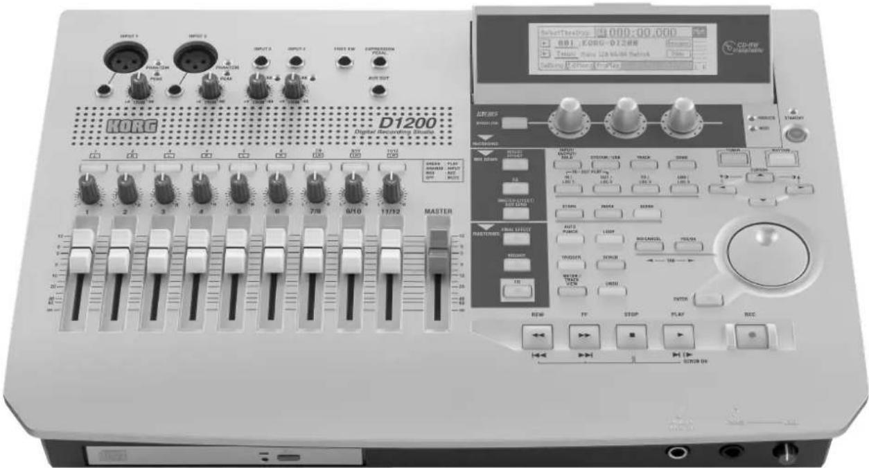
Digital Recording Studio
Owner's Manual

CD-RW
installable
REMS
Precautions
Location
Using the unit in the following locations can result in a malfunction.
- In direct sunlight
- Locations of extreme temperature or humidity
• Excessively dusty or dirty locations - Locations of excessive vibration
- Close to magnetic fields
Power supply
Please connect the designated AC/DC power supply to an AC outlet of the correct voltage. Do not connect it to an AC outlet of voltage other than that for which your unit is intended.
Interference with other electrical devices
Radios and televisions placed nearby may experience reception interference. Operate this unit at a suitable distance from radios and televisions.
Handling
To avoid breakage, do not apply excessive force to the switches or controls.
Care
If the exterior becomes dirty, wipe it with a clean, dry cloth. Do not use liquid cleaners such as benzene or thinner, or cleaning compounds or flammable polishes.
Keep this manual
After reading this manual, please keep it for later reference.
Keeping foreign matter out of your equipment
Never set any container with liquid in it near this equipment. If liquid gets into the equipment, it could cause a breakdown, fire, or electrical shock.
Be careful not to let metal objects get into the equipment. If something does slip into the equipment, unplug the AC/DC power supply from the wall outlet. Then contact your nearest Korg dealer or the store where the equipment was purchased.
THE FCC REGULATION WARNING (for U.S.A.)
This equipment has been tested and found to comply with the limits for a Class B digital device, pursuant to Part 15 of the FCC Rules. These limits are designed to provide reasonable protection against harmful interference in a residential installation. This equipment generates, uses, and can radiate radio frequency energy and, if not installed and used in accordance with the instructions, may cause harmful interference to radio communications. However, there is no guarantee that interference will not occur in a particular installation. If this equipment does cause harmful interference to radio or television reception, which can be determined by turning the equipment off and on, the user is encouraged to try to correct the interference by one or more of the following measures:
- Reorient or relocate the receiving antenna.
- Increase the separation between the equipment and receiver.
- Connect the equipment into an outlet on a circuit different from that to which the receiver is connected.
- Consult the dealer or an experienced radio/TV technician for help.
Unauthorized changes or modification to this system can void the user's authority to operate this equipment.
CE mark for European Harmonized Standards CE mark which is attached to our company's products of AC mains operated apparatus until December 31, 1996 means it conforms to EMC Directive (89/336/EEC) and CE mark Directive (93/68/EEC). And, CE mark which is attached after January 1, 1997 means it conforms to EMC Directive (89/336/EEC), CE mark Directive (93/68/EEC) and Low Voltage Directive (73/23/EEC).
Also, CE mark which is attached to our company's products of Battery operated apparatus means it conforms to EMC Directive (89/336/EEC) and CE mark Directive (93/68/EEC).
Handling of the internal hard disk
Do not apply physical shock to this device. In particular, you must never move this device or apply physical shock while the power is turned on. This can cause part or all of the data on disk to be lost, or may damage the hard disk or interior components.
When this device is moved to a location where the temperature is radically different, water droplets may condense on the hard disk. If the device is used in this condition, it may malfunction, so please allow several hours to pass before operating the device.
Do not repeatedly turn the power on/off. This may damage the D1200.
This device begins to access the hard disk immediately after the power is turned on.
Never turn off the power while the HDD access indicator is lit or blinking. Doing so can cause all or part of the data on hard disk to be lost, or may cause malfunctions such as hard disk damage.
If the hard disk has been damaged due to incorrect operation, power failure, or accidental interruption of the power supply, a fee may be charged for replacement even if this device is still within its warranty period.
COPYRIGHT WARNING
This professional device is intended only for use with works for which you yourself own the copyright, for which you have received permission from the copyright holder to publicly perform, record, broadcast, sell, and duplicate, or in connection with activities which constitute “fair use” under copyright law. If you are not the copyright holder, have not received permission from the copyright holder, or have not engaged in fair use of the works, you may be violating copyright law, and may be liable for damages and penalties. If you are unsure about your rights to a work, please consult a copyright attorney. KORG TAKES NO RESPONSIBILITY FOR ANY INFRINGEMENT COMMITTED THROUGH USE OF KORG PRODUCTS.
Table of Contents
Introduction ...... 5
Main features .... 5
Conventions in this manual....6
Parts and their function.... 7
Top panel....7
Front panel 10
Rear panel....11
Objects in the display and their function .....12
Basic operation ....13
-
Selecting a mode.... 13
-
Selecting a tab page.... 13
-
Selecting and editing a parameter 13
Preparations ....14
-
Connections.... 14
-
Turning the power on/off.... 15
-
Display.... 16
Listening to the demo song .....16
Quick Start Tutorial......17
Step 1: Quick recording....17
-
Getting ready 17
-
Turning on the power.... 17
-
Creating a new song 18
-
Using the modeling mode.... 18
-
Setting up a rhythm 20
-
Recording 20
-
Play back.... 21
Step 2: Overdubbing ...... 22
-
Assigning inputs to the mixer 22
-
Applying an insert effect to the keyboard. ..... 23
-
Overdubbing.... 23
-
Overdubbing additional parts.... 24
Step 3. Mixing ......25
-
Applying an insert effect to a track 25
-
Adding EQ (equalization) to each track.... 26
-
Applying master effects to all tracks 27
Step 4. Mastering ...... 28
-
Applying the final effect.... 28
-
Creating the master track.... 28
-
Writing to CD.... 29
Operation.... 31
Song and Locate 31
-
Creating, naming and selecting songs ....31
-
Using the counter display....32
-
Editing a song 34
Mixer.... 35
-
Inputting audio to the mixer 35
-
Adjusting the mixer ....37
-
Registering and recalling a scene....39
Effects 42
-
Using insert effects....42
-
Using the master effects ....43
-
Using the final effect....43
-
Editing an effect....43
-
Controlling an effect from an external device .....44
-
Using an external effect....45
Modeling mode.... 45
-
Applying a modeling effect to your guitar .....45
-
Applying a modeling effect to your bass .....46
-
Applying a modeling effect to a mic ....46
-
Saving your modeling effect settings....46
-
Operation in Modeling mode....47
Rhythm 48
-
Selecting and playing a rhythm ....48
-
Listening to the rhythm while you record a performance....48
-
Recording the rhythm 48
-
Setting the tempo of a song 49
The Recorder 53
-
Recording 53
-
Playback ....56
-
Track editing....57
Mastering 64
-
Bounce-recording....64
-
Creating an original CD 65
-
Recording to a master tape 67
-
Using sub inputs 67
Data 68
-
Backing up and restoring song data....68
-
Backing up and restoring effect user data....70
-
Reading and writing WAV files....71
-
Drive and data compatibility between models of the Digital Recording Studio series ....74
Drive 75
-
Checking the hard disk ....75
-
Formatting the hard disk ....75
-
Erasing a CD-RW disc ....76
-
Drive capacity....76
USB 77
- Saving data to your computer....77
MIDI....79
-
MIDI connections....79
-
MIDI messages used by the D1200....79
-
Using MIDI 79
Upgrading the system ....81
- Downloading the system file.... 81
- Upgrading the system....81
Reference 83
(COUNTER) 84
Counter: Counter display.... 84
MODELING....84
Category: Select an effect category 84
Modeling 1....84
Modeling 2....85
INSERT EFFECT 85
InsAss: Specify the insert location and type of the insert effects....85
InsEff1: Select and edit insert effect 1 .... 86
InsEff2: Select and edit insert effect 2 ....87
InsEff3: Select and edit insert effect 3 .... 87
InsEff4: Select and edit insert effect 4 .... 88
InsEff5-8: Select and edit insert effects 5-8 .... 88
EQ 88
Eq1-4: Adjust the EQ for mixer channels 1-4 .... 88
Eq5-8: Adjust the EQ for mixer channels 5-8 ...... 88
Eq9–12: Adjust the EQ for mixer channels 9–12 ..... 89
MASTER EFFECT/AUX SEND 89
MstEff1: Select and edit master effect 1....89
MstEff2: Select and edit master effect 2....90
EffSnd1: Adjust send levels to master effect 1.....90
EffSnd2: Adjust send levels to master effect 2...... 90
AuxSend: Adjust the external send levels ..... 90
FINAL EFFECT 91
FinalEff: Select and edit the final effect 91
BOUNCE....92
RecMode: Select the recording mode 92
Bounce: Parameters for bounce-recording.... 92
CD....93
Prepare: Prepare to create an audio CD.... 93
CDR/RW: Create and play back an audio CD ..... 93
TUNER....95
RHYTHM 95
SetUp: Specify the tempo and rhythm 95
TmpMap: Tempo map editing 96
TmpTrk: Create a tempo track.... 97
INPUT/OUTPUT/SOLO....98
Ch1-6: Select inputs for mixer channels 1-6 .... 98
Ch7-12: Select inputs for mixer channels 7-12 ..... 98
InEq1-4: Adjust the EQ for inputs 1-4 .... 99
Solo: Select the signal to be soloed....99
Monitor: Parameters and settings 100
Phase: Specify the phase of the mixer channels..... 100
SYSTEM/USB....101
Control: Foot switch and control change device (pedal/MIDI) settings.... 101
MIDI: MIDI settings 101
Sync: Synchronization settings.... 102
MMC: MMC settings.... 102
B-U/Rst: Backup and restore.... 102
DiskUtil: Disk drive management 105
TRACK 108
Vtr1-6: Select virtual tracks 1-6 .... 108
Vtr7-12: Select virtual tracks 7-12 .... 108
EditTrk: Perform track editing operations ..... 108
Import: Import WAV files.... 113
Export: Export a WAV file 114
SONG 116
SelSong: Select a song 116
EditSong: Perform song edit operations.... 116
PrgPlay: Program playback of songs.... 118
IN/LOC1, OUT/LOC2, TO/LOC3, END/LOC4.....118
MARK 119
Mark: Edit marks.... 119
SCENE 120
ReadDel: Switch scene playback on/off, and edit scenes 120
MixView: Viewing pan and fader scene data ..... 121
AUTO PUNCH ....122
AtPunch: Settings for auto punch-in/out recording 122
LOOP....123
Loop: Settings for loop playback and recording .... 123
TRIGGER 123
Trigger: Settings for trigger recording 123
SCRUB 124
METER/TRACK VIEW....125
UNDO ....126
Effect Parameter List.....127
Insert (2in2outx2)/Master/Final Effect ......127
Insert (2in2outx2), Final ....133
Insert (1in2outx2) 134
Insert (1in1outx4) 138
Insert (1in1outx8) 140
Effect Control ....141
Modeling effects ......141
Appendix.... 143
Troubleshooting 143
Nothing appears in the display.... 143
No sound 143
Channel fader or EQ does not work.... 143
Can't use digital input 144
The input or recorded sound is noisy or distorted. 144
Effects do not apply 144
Rhythm 145
A key does not function when pressed.... 145
MIDI 145
CD-R/RW....146
WAV....146
USB 146
Messages.... 147
Confirmation messages 147
Error messages.... 147
About the CDRW-1 149
-
Cautions for handling.... 149
-
Installing the CDRW-1.... 149
-
Inserting a disc.... 150
-
Removing a disc 150
-
Using the CDRW-1.... 151
D1200 specifications.... 152
Effect Program List.... 154
Rhythm Pattern List (215patterns).... 156
Index 157
Block diagram.... 159
MIDI implementation chart 160
Introduction
Thank you for purchasing the Korg D1200 Digital Recording Studio.
To take full advantage of the D1200's functions and enjoy trouble-free use, please read this manual carefully and use the product as directed. Keep this manual in a safe place for future reference.
Main features
12-track digital multi-track recorder
In a compact package, the D1200 provides the studio-quality sound that you expect from Korg, with 24-bit recording and 16/24-bit uncompressed playback at a sampling frequency of 44.1 kHz. A maximum of 12 tracks can be played back simultaneously (for 16-bit data), and up to four tracks can be recorded simultaneously. Recording time is a maximum of approximately 186 hours (when recording one track at 16-bit resolution). Each track provides eight virtual tracks, so you can record as many as 96 tracks in one song.
XLR connectors with +48 V phantom power, analog inputs, dedicated guitar input jack, and digital connectors
All analog inputs of the D1200 use high-performance balanced head amps in order to take full advantage of the audio quality provided by full-digital processing. The two XLR input jacks provide +48 V phantom power and have high-quality mic preamps, allowing condenser mics to be connected directly. All phone-jack inputs are balanced TRS types, and also support unbalanced input. Input sources for a range of levels from mic level to +16 dBu (higher than professional level) can be connected. A dedicated guitar input jack is also provided. The S/P DIF digital input contains a sampling rate converter which automatically converts 48 kHz and 32 kHz sources to 44.1 kHz, allowing them to be recorded.
Mixer section provides three-band EQ with sweepable mid-range. 100 scene memories and mixer data transmission/reception via MIDI.
The 16-channel 4-bus mixer section of the D1200 provides three-band EQ on each analog input and mixer channel. High and low EQ are shelving types, and the mid EQ is an adjustable peaking type with a sweepable center frequency. Since separate EQ is provided for the inputs and for the mixer, you won't need to worry about recording EQ settings being re-applied to the playback – a problem that often occurs on MTR units containing analog mixers.
The faders, EQ, pan, and effect settings of the mixer can be stored in one of 100 scenes. Scenes can be recalled automatically as playback time passes, or can be recalled immediately at any time as general-purpose settings.
MIDI can be used to transmit and receive mixer data such as fader and pan, allowing you to use an external sequencer to perform mixer automation.
Powerful modeling effects with easy icon and knob-based operation.
The internal effects use Korg's "Modeling technology to deliver detailed and powerful modeling sounds. "Modeling mode" lets you use easily understandable icon displays and three modeling effect knobs to select modeling effects for guitar or bass, edit the parameters, and modify values – just by using icons and knobs.
As modeling effects, the D1200 provides ten distortion-type effects for guitar, a vacuum tube simulator, and eleven types of cabinet from famous amps from around the world. For bass, choose from three dynamics-type effects and five types of modulation/spatial effects such as chorus and delay. For mics, you can use studio simulators with six types of room size and resonance, seven types of mic simulation ranging from vintage tube mics to modern studio condenser mics, and three dynamics-type effects.
When using Modeling mode, the Auto Routing function lets you record immediately by simply selecting the desired track.
Three independent effect systems for simultaneous use
The D1200 contains three independent effects system, all of which use 44-bit internal processing; Insert, Master, and Final effects. The settings for each of the insert, master, and final effects can be saved as one of the 192 user effect programs. Each program can combine up to five of the 98 available high-quality effect types. Internal memory contains 128 insert, 32 master, and 32 final effect programs for a total of 192 preset programs, all created by professional musicians and studio engineers. You can also edit a preset program and save your own settings effect program in one of the 192 user areas.
An external MIDI controller or expression pedal (separately sold EXP-2 or XVP-10) can also be used to control the insert effect in realtime.
Sophisticated editing functionality
The D1200 lets you use the non-destructive editing functions available only on digital recorders to edit your sound without impairing its pristine quality. You can use auto or manual punch-in/out recording. Using the convenient Undo and Redo feature, as many as 99 of the last recording or editing operations can be cancelled or recalled. The ten types of track editing operation include Time Expansion/Compression which lets you match the tempo of previously-recorded phrases of differing tempo, and Normalize which boosts under-recorded tracks to an appropriate level.
You can assign as many as one hundred marker points to each song, and specify four locate points for easy access to song locations for editing.
High-capacity built-in 40 GB hard disk drive. USB connector for smooth data exchange with an external USB hard disk drive or computer.
A high-capacity 40 GB hard disk drive is built-in. Of the capacity of this drive, 2 GB is allocated as a "USB drive*" that can be used from a computer connected to the USB connector, allowing data to be shared. The remaining capacity is used as the "song drive" for storing songs. Since WAV files can be imported or exported, it's easy to transfer audio data to or from your computer.
*FAT16 compatible
Optional CDRW-1 CD-R/RW drive lets you create audio CDs
If the CDRW-1 CD-R/RW drive (sold separately) is installed, you can use it to backup/restore songs or effect data, export/import WAVE files, or create audio CDs. You can also insert an audio CD in the drive, patch the signal to a mixer channel, and record it. When writing an Audio CD, you can write each song separately (Track At Once), or write the entire disc in one operation (Disc At Once) for example to make a CD of a continuous live performance where markers are inserted in the song to indicate the tracks of the audio CD.
Auto chromatic tuner function
An auto chromatic tuner is built-in, letting you to tune a connected guitar or other instrument. The panel provides dedicated keys for the tuner, for tuning at any time.
Backlit LCD display with adjustable angle
The backlit 240 · 64 pixel LCD screen is easily readable even in dim locations, and you can adjust the angle for best visibility. The display contrast is also adjustable.
Auto Save function automatically preserves your data at power-off
The D1200 features an Auto Save function that automatically saves your recorded or edited songs and phrases to the hard disk whenever you switch songs or turn off the power.
What is 2EMS
REIMS (Resonant structure and Electronic circuit Modeling System) is Korg's proprietary technology for digitally recreating the numerous factors that produce and influence a sound, ranging from the sound-production mechanisms of acoustic instruments and electric/electronic musical instruments, to the resonances of an instrument body or speaker cabinet, the sound field in which the instrument is played, the propagation route of the sound, the electrical and acoustic response of mics and speakers, and the changes produced by vacuum tubes and transistors.
Conventions in this manual
Keys, switches and knobs [ ]
Keys, dials, and knobs etc. located on the panel of the D1200 are enclosed in square brackets [ ].
Parameters appearing in the display " "
Parameters that appear in the display are enclosed by double quotation marks “”. Buttons and cells refer to objects in the display.
To select a parameter shown in the display, use the [CURSOR] keys to move the cursor to that parameter. (→ p.13)
Bold type
Settings of panel controls such as faders or [TRACK STATUS] keys are printed in bold type, and parameter values are also indicated by "bold type." Bold type is also used to emphasize important content in the text.
Steps ① ② ③ ...
Steps in a procedure are indicated as ① ② ③ ...
→p. ■ ■
This indicates a page in this manual to which you can refer for more information.
note
These symbols indicate cautions or advice.
[...] "OO" tab page
This indicates a page within the display. To access that page, press the [...] key on the panel.
Screen displays in this manual
The values of various parameters in this manual are only explanatory examples, and may not necessary match the displays that appear on your D1200.
Parts and their function
Top panel
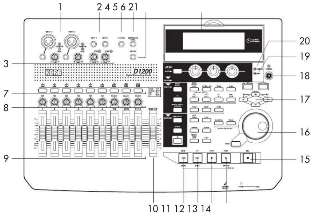
1 [INPUT 1], [INPUT 2] jacks
Use these jacks to input mic/line signals (such as from a keyboard).
You can use either XLR jacks or TRS phone jacks, and both sets of jacks are balanced.
Unbalanced phone plugs can also be connected.
The XLR jacks can supply +48 V phantom power to condenser mics.
Note If you connect a plug to the phone jack, no signal can be input from the corresponding XLR jack. If you want to use the XLR jack, disconnect any plug from the corresponding phone jack.
Note If you connect a plug to the [GUITAR IN] jack, no signal can be input from the [INPUT 1] jack. If you want to input a signal from the [INPUT 1] jack, disconnect any plug from the [GUITAR IN] jack.
note These TRS phone jacks do not individually allow stereo input.
2 [INPUT 3], [INPUT 4] jacks
Use these jacks to input mic/line signals (such as from a keyboard).
These are balanced TRS phone jacks. Unbalanced phone plugs can also be connected.
note These TRS phone jacks do not individually allow stereo input.
3 [TRIM] knob: -60...-10...+4 dBu
These knobs adjust the input level. Input level calibration marks are printed on the panel. Adjust the [TRIM] knobs so that the peak indicators (the LEDs near each knob) light when the input level of the connected instrument or device is loudest.
Although the input level will depend on the device or performance, here are some guidelines for setting these knobs.
-60 - -40 dBu: mic input
-30 dBu: guitar or bass guitar
-10 dBu: CD player or other consumer audio device
+4 dBu: keyboard or studio equipment
If nothing is connected, you may hear hum or noise when you raise the [TRIM] knobs.
4 [FOOT SW] jack
A foot switch connected to this jack can be used to operate basic recorder functions when your hands are occupied by playing an instrument.
You can use a foot switch to control play/stop, to start/stop manual punch-recording, to register a mark, or to record tap tempo. (→ p.101)
Connect a PS-1 foot switch (sold separately) to this jack.
5 [EXPRESSION PEDAL] jack
A pedal connected to this jack can be used to control a specified parameter of an insert effect. This lets you control an effect in realtime while you perform or record. (→ p.44)
Connect an EXP-2 or XVP-10 expression pedal (sold separately) to this jack.
6 [AUX OUT] jack
This outputs the external send audio signal from each mixer channel. (The send amount is adjusted in the [MASTER EFFECT/AUX SEND] "AuxSnd" tab page.)
Connect this jack to an external effect processor. This is a phone jack.
7 [TRACK STATUS] keys
These keys are used to switch each track between play/record or mute states. The status of the track will alternate each time you press the key.
PLAY (LED lit green): The track can be played.
REC (LED lit red): The track can be recorded. When recording from the analog/digital inputs, you can select up to four tracks for recording (two tracks in Modeling mode).
INPUT (LED lit orange): The track can receive an external audio signal. This state can be selected only while stopped.
Select this when you want to perform while listening to other tracks so that you can rehearse before recording, or if you want to mix an external input source with the playback.
MUTE (LED dark): The track is muted (silent).
The states that can be selected will depend on the state and settings of the recorder.
While stopped: PLAY → INPUT → REC → MUTE → PLAY
While recording or playing: PLAY MUTE, INPUT MUTE
Modeling mode: PLAY → REC → MUTE → PLAY
note These settings can be paired, or registered in a scene.
8 [ P AN] knobs (Ch1...6), [BALANCE] knobs (Ch7...12)
For each channel, these knobs adjust the position (pan) or left/right balance of the stereo signal to the master LR bus ( p.37).
For channels 1–6 for which pairing is "Off," these knobs control panning to the master LR bus.
For channels 1–6 for which pairing is "On" and for channels 7–12, these knobs control the left/right balance of the stereo signal to the master LR bus.
note These settings can be paired, or registered in a scene.
When recording to channels that have a balance setting, you must set the knob to "CNT."
9 [CHANNEL] faders (Ch1...6, Ch7/8...11/12)
These faders adjust the recording/playback volume of each channel ( p.37).
Channels 7–12 are stereo faders.
note These settings can be paired, or registered in a scene.
- For channels whose [TRACK STATUS] is PLAY, the fader adjusts the playback volume.
- For channels whose [TRACK STATUS] is REC, the fader adjusts the recording level of the external audio source or the rhythm.
- For channels whose [TRACK STATUS] is INPUT, the fader adjusts the recording level of the external audio source.
note Faders that adjust the recording level will function differently depending on whether an external input is being recorded or bounce recording is being performed.
- When recording an external input (i.e., when the [BOUNCE] "RecMode" tab page "Select RecMode" parameter is set to "Input"), the channel fader adjusts the recording level.
10 [MASTER] fader
This fader adjusts the overall volume of all channels. The volume adjusted by this fader is output from the [MASTER OUT L/R] jacks and the [S/P DIF OUT] jack.
- When recording an external input (i.e., when the [BOUNCE] "RecMode" tab page "Select RecMode"
parameter is set to "Input"), the master fader adjusts the volume level of the master LR bus.
- When bounce-recording (i.e., when the [BOUNCE] "RecMode" tab page "Select RecMode" parameter is set to "Bounce"), the master fader adjusts the recording level to the track(s) whose [TRACK STATUS] is REC.
11 [REW] key
This key changes the location to an earlier time (rewind) while stopped or moving. If you hold down the [STOP] key and press the [REW] key, you will move to the previous-numbered song (if you are already at the beginning of the song) or to the beginning of the current song (if you are in the middle of the song).
12 [FF] key
This key changes the location to a later time (fast-forward) while stopped or playing. If you hold down the [STOP] key and press this key, you will move to the end of the current song (if not already at the end) or to the beginning of the next song (if you are already at the end of the current song). If the Scrub function is on, you can press this key to perform Slow Play ( p.34).
13 [STOP] key
This key stops recording or playback, halting the recorder.
14 [PLAY] key
This key plays tracks whose [TRACK STATUS] is PLAY. For tracks whose [TRACK STATUS] is REC, pressing the [REC] key and then this key will begin recording. The LED of this key will light while the recorder is recording or playing.
If the Scrub function is on, pressing this key will perform Play From, and pressing this key while holding down the [STOP] key will perform Play To. ( p.34)
15 [REC] key
Press this key to enter record-ready mode (the LED will blink). In order to enter record-ready mode, one or more tracks must be set to a [TRACK STATUS] of REC. When you press the [PLAY] key, the LED will light and recording will begin.
Note If the foot switch function ( p.101) is set to "PunchIn Out", the foot switch will perform the same function as the [REC] key.
16 [VALUE] dial
Use this dial to edit values or to move the current location.
If the Scrub function is on, turning this dial will play the track at the corresponding speed.
17 [CURSOR] keys
These keys move the cursor. They are also used to adjust the contrast (brightness) of the display.
18 [POWER] key
This key turns the power on/off. ( p.15)
19 MIDI indicator
This indicator will light when a MIDI message is received at the MIDI IN connector.
20 HDD/CD access indicator
This indicator will light when the hard disk is being accessed during recording, playback, or editing, or if an installed CD-R/RW drive is operating.
Never subject the D1200 to vibration or shock while this HDD/CD access indicator is lit.
21 Display
This shows various information such as the volume (level meters) during recording or playback, the time (locate), and parameter settings. (→p.13)
You can adjust the angle of the display for best visibility.
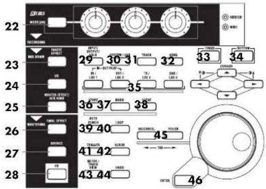
22 [MODELING] key, [MODELING] knobs
This key lets you use effects for guitar, bass, and mic as easily as if you were actually using dedicated hardware devices. The effects are controlled by the three knobs located below the display. Since there is no need to make complicated preparations for recording, you can easily apply an effect and record. (→p.45, 84)
23 [INSERT EFFECT] key
This key selects the location at which an insert effect is inserted, selects the effect type, and select and edits effect programs. ( p.42, 85)
note These settings can be registered in a scene.
24 [EQ] key
Use this key to adjust the EQ (for track playback) of each channel. (→p.37, 88)
note These settings can be paired, and registered in a scene.
25 [MASTER EFFECT/AUX SEND] key
Use this key to select and edit effect programs for master effects 1 and 2, and to set the send level from each channel to the master effects. This key is also used to set the send level to an external effect. (→ p.45, 89)
Note These settings can be registered in a scene. Send settings can also be paired.
26 [FINAL EFFECT] key
Use this key to select and edit effect programs for the final effect. (→p.43, 91)
27 [BOUNCE] key
Use this key to make recorder settings such as selecting the recording source and the bounce-record method. (→p.64, 92)
28 [CD] key
Use this key to create an audio CD. (→p.65, 93)
note In order to use this key, the CDRW-1 CD-R/RW drive option (sold separately) must be installed. (→p.149)
29 [INPUT/OUTPUT/SOLO] key
Use this key to select the mixer channel to which the audio signal from each input jack will be input. (→p.98) This key is also used to adjust the EQ applied to the analog inputs (for recording).
It is also used to solo channels, send, and returns. When solo is on, the LED will blink.
Additionally, this key lets you select the audio signal for monitor output, and specify the phase of each channel.
30 [SYSTEM/USB] key
This key lets you make various settings for the foot switch and MIDI, to manage the disk, and to perform backup and restore your data. (→p.101)
You can also connect your computer to the D1200 via the USB connector, and exchange data between your computer and the USB drive of the D1200.
31 [TRACK] key
Use this key to select the virtual track for each track, to perform track editing operations such as copy or delete, and to import or export a WAV file. (→p.108)
32 [SONG] key
Use this key to create a new song, rename or select a song, perform song edit operations such as copy or move, and to perform program-playback of songs. (→p.116)
33 [TUNER] key
Press this key when you want to use the tuner. (→p.36, 95)
34 [RHYTHM] key
Use this key to switch the internal rhythm pattern play-back on/off, set the song tempo, and create tempo maps. The key will light if the rhythm is on. (→p.48, 95)
35 [IN/LOC1] key, [OUT/LOC2] key, [TO/LOC3] key, [END/LOC4] key
Use these keys to register a desired location within the song, or to instantly recall a registered location.
The locations registered here will be used as the punch-in/out points, and as the locations for track editing operations such as copy or delete. (→p.33, 118)
By holding down the [IN/LOC1] key and pressing the [OUT/LOC2] key, you can listen to the audio between the IN-OUT points.
36 [STORE] key
Press this key to register a location for a locate point, mark, or scene.
The location at which you pressed the [STORE] key will be preserved, and you can then press a desired key to specify the memory in which this location will be stored. To discard the location that was preserved, press the [STORE] key once again instead of pressing a locate memory key.
For details on these functions and on how to register a location, refer to Locate ( p.32), Mark ( p.39), or Scene ( p.39).
37 [MARK] key
Use this key to register a desired location within the song as a Mark, or to jump instantly to a previously-registered mark.
This key is also used to edit the marks you have registered, for example by renaming or deleting them. (→p.33, 119)
When you create an audio CD using the Disc At Once method, these markers are used to separate the tracks. (→p.66)
38 [SCENE] key
Use this key to register settings such as [CHANNEL] faders, [PAN]/[BALANCE] knobs, EQ, and effect send as a "scene" at the desired time within the song. If Scene Read is turned on when you play back, the registered scene will be selected automatically. You can also use this key to perform scene editing operations such as sort, rename, or delete (→p.39, 120). This key will light if Scene Read is on.
39 [AUTO PUNCH] key
Use this key to turn the auto punch-in/out function on/off, to make pre/post-roll settings, and to check the start/end locations. (→p.54, 122)
This key will light if Auto Punch-in/out is on.
40 [LOOP] key
Use this key to switch looping on/off for recording or playback, and to check the start/end locations. (→p.123) This key will light if Loop is turned on.
41 [TRIGGER] key
Use this key to switch Trigger Recording on/off, allowing you to automatically start recording when an input signal occurs. This key also lets you set the threshold level and pre-trigger time. (→p.54, 123)
This key will light if the Trigger Recording function is on.
42 [SCRUB] key
Use this key to switch the Scrub, Play To/From, or Slow Play functions on/off. You can use these different functions by controlling the [VALUE] dial and TRANSPORT keys. (→p.124)
43 [METER/TRACK VIEW] key
Use this key to view volume data during recording or playback (level meters), and audio event data (track view) for each track. ( p.125)
44 [UNDO] key
After you have recorded on a track or performed an editing operation, you can use this key to perform Undo (which returns the data to its prior state) or to perform Redo (which cancels the Undo and returns the data to the recorded or edited state).
You can use this to cancel or recall as many as 99 previous recording or editing operations. You can select either 1, 8, or 99 times as the number of operations that will be allowed for the Undo function. (→p.126) This key will light if Undo or Redo is available.
45 [NO/CANCEL] key, [YES/OK] key
Use these keys as the "Yes" / "OK" or "No" / "CANCEL" buttons that appear in the display. In addition, the [NO/CANCEL] key moves back to the previous tab page, and the [YES/OK] key proceeds to the next tab page.
46 [ENTER] key
Use this key to finalize a parameter setting or on/off setting.
Front panel
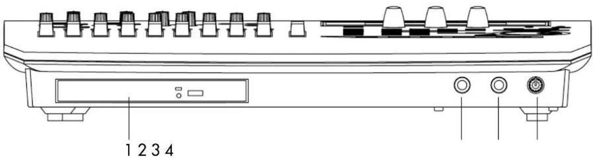
1 CDRW-1 drive bay
The CDRW-1 CD-R/RW drive option (sold separately) can be installed in this bay. (→p.149)
2 [GUITAR IN] jack
You can connect a guitar or bass guitar to this jack. This is an unbalanced phone input jack with an impedance of 1 MΩ.
3 [PHONES] jack
You can connect a set of headphones to this jack. This is a stereo phone jack. It outputs the same signal as [MONITOR OUT L/R].
4 [PHONES LEVEL] knob: 0...10
This knob adjusts the volume level of the headphones. Larger markings indicate a higher volume.
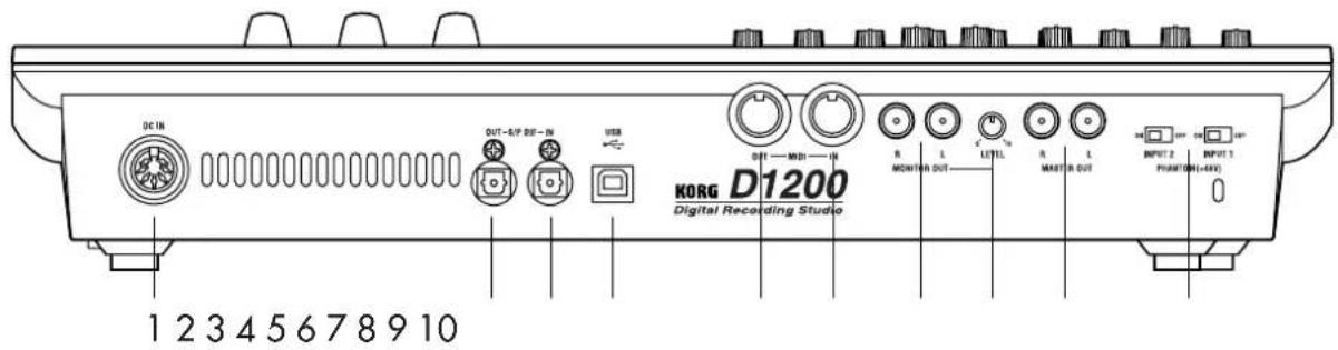
Rear panel
1 [DC IN] connector
Connect the included AC/DC power supply to this connector.
2 [S/P DIF OUT] jack
This is an optical S/P DIF format (IEC60958, EIAJ CP-1201) digital output jack (stereo).
You can use an optical cable to connect it to the optical digital input jack of a DAT or MD.
The same audio signal as the [MASTER OUT L/R] jacks is digitally output from this jack at a sampling rate of 44.1 kHz.
3 [S/P DIF IN] jack
This is an optical S/P DIF format (IEC60958, EIAJ CP-1201) digital input jack (stereo).
You can use an optical cable to connect it to the optical digital output jack of a DAT or MD. Use a digital cable that is no longer than 5 meters.
This jack contains a built-in sampling rate converter. If the source connected here has a sampling rate of 48 kHz or 32 kHz, it will automatically be converted to 44.1 kHz.
96 kHz is not supported.
4 [USB] connector
You can use a USB cable to connect this to your computer.
It is not possible to connect USB peripheral devices (such as an external hard disk or CD-R/RW drive) to the D1200.
5 [MIDI OUT] connector
This connector transmits MIDI data. Use it when you want to control a connected external MIDI device from the D1200. (→p.79)
6 [MIDI IN] connector
This connector receives MIDI data. Use it when you want to control the D1200 from a connected external MIDI device. (→p.79)
7 [MONITOR OUT L/R] jacks
Connect your external monitor system to these jacks. You can select the bus for monitor output in the [INPUT/OUTPUT/SOLO] "Monitor" tab page ( p.100). These jacks output the same signal as the [PHONES] jack. These are RCA phono jacks.
8 [MONITOR OUT LEVEL] knob
This knob adjusts the volume that is output from the [MONITOR OUT L/R] jacks.
9 [MASTER OUT L/R] jacks
These are analog audio outputs for the master LR bus signal that combines the signals of each mixer channel into a two-channel mix, or the audio signal that is selected for soloing. To select a solo signal, make settings in the [INPUT/OUTPUT/SOLO] "Solo" tab page. Connect these jacks to your external monitor system or recording device. They output the same audio signal as the [S/P DIF OUT] jack.
These are RCA phono jacks.
10 [Phantom power] switch
+48 V phantom power is supplied to the [INPUT 1, 2] jacks, allowing you to use condenser mics. Phantom power is supplied to the balanced XLR jacks, and can be switched on/off independently for each channel. Turn on this switch only for channels that are using a condenser mic.
You may damage your equipment if you connect or disconnect a condenser mic while phantom power is turned on. Always turn phantom power off before you connect or disconnect a condenser mic.
Never connect an dynamic type, other type mic or device if phantom power is turned on. Doing so may damage your equipment.
Objects in the display and their function
Objects in the display
To select an object shown in the display, use the [CURSOR] keys to select it, and press the [ENTER] key.
In this manual, references enclosed in double quotation marks such as “...”, “...” button, or “...” tab refer to objects in the display. On the other hand, references enclosed in square brackets such as [...] key, [...] knob, [...] dial, or [...] fader refer to controls or items on the front panel or rear panel of the D1200.
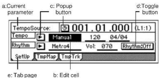
a: Current parameter
This is the name of the parameter that is currently selected by the cursor.
In the case of icon-type parameters such as EQ or faders, the value is shown at the right.
b: Edit cell
This is a parameter that is underlined in the display. When you use the cursor to select an edit cell, the parameter value display will be highlighted, and can be edited.
To edit the parameter value in the edit cell, use the [VALUE] dial ( p.8) or popup buttons in the display.
c: Popup button
When you select one of these buttons and press the [ENTER] key, a dialog box (f) will appear.
To input a parameter value, select the desired value in the dialog box.

d: Toggle button
This type of button will switch a function on/off each time you select it and press the [ENTER] key. The frame will become thicker when selected.

e: Tab page
Each mode contains numerous parameters, which are organized into pages. These pages are divided by tabs.
g: Radio buttons f: Dialog box
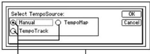
f: Dialog box
Press the [YES/OK] key to execute, or the [NO/CANCEL] key to close the dialog box without executing. You can also make your choice by selecting the "OK" or "Cancel" button, and pressing the [ENTER] key.
g: Radio buttons
This type of button is used to select one of multiple choices. Select one of the radio buttons and press the [ENTER] key.
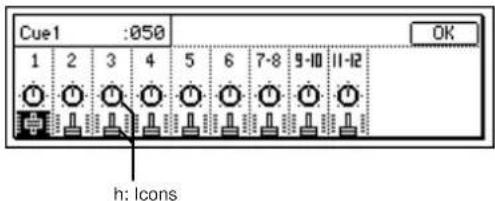
h: Icons
These are objects shaped like sliders or knobs. To edit the value, select the icon and turn the [VALUE] dial.
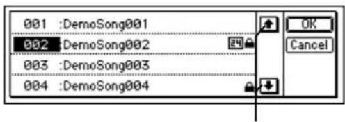
i: Scroll buttons
i: Scroll buttons
Use these to see parameters that are not currently shown in the display.
Basic operation
1. Selecting a mode
The various function of the D1200 are organized under different modes. To access a specific feature, select the mode that contains the desired function by pressing its key.
For details on the functions within each mode, refer to "Reference" ( p.83).
2. Selecting a tab page
Each mode contains numerous parameters, which are organized into pages. These pages are divided by tabs.
① Press the key of the desired mode.
The following screen shows a page in RHYTHM mode which will appear when you press the [RHYTHM] key.
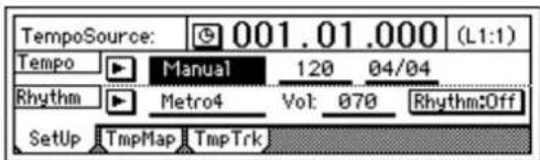
② Select the desired tab page.
Use the [YES/OK] and [NO/CANCEL] keys to select the tab page.
You can also step through the tab pages by repeatedly pressing the key of the currently selected mode.
note Some pages contain only one tab.
3. Selecting and editing a parameter
Selecting a parameter
Toedit a parameter, use the [CURSOR] keys to select the parameter you want to edit.
In a list display, turn the [VALUE] dial to move the cursor.
Editing a parameter value
The way in which you edit or set a parameter value will depend on the type of parameter.
○ Underlined “__” parameters, or icons such as EQ
Use the [CURSOR] keys to move the cursor to the parameter, highlighting it. Then turn the [VALUE] dial to specify the value.
This is the typical method, and also applies to underlined parameters such as "Tempo," parameters such as EQ that are indicated by icons, and locate times.
○ Popup buttons and dialog boxes
Use the popup button to open the dialog box, and specify the parameter value ( p.12)
- Use the [CURSOR] keys to move the cursor to the popup button, and press the ENTER button to open the dialog box.
○ Toggle buttons
These are used to switch functions or on/off settings ( p.12).
- Use the [CURSOR] keys to select the parameter, and press the [ENTER] key. The setting will be switched on/off each time you press the key.
○ Radio buttons
These are used to select one of multiple choices.
- Use the [CURSOR] keys to move the cursor to the desired selection, and press the [ENTER] key.
○ Selecting one item from a list
- To select a song or mark, turn the [VALUE] dial select the desired item.
- To select a song in the program playback list, use the following procedure.
① Select the playback list number.
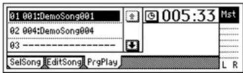
② Turn the [VALUE] dial to select a song.
Preparations
1. Connections
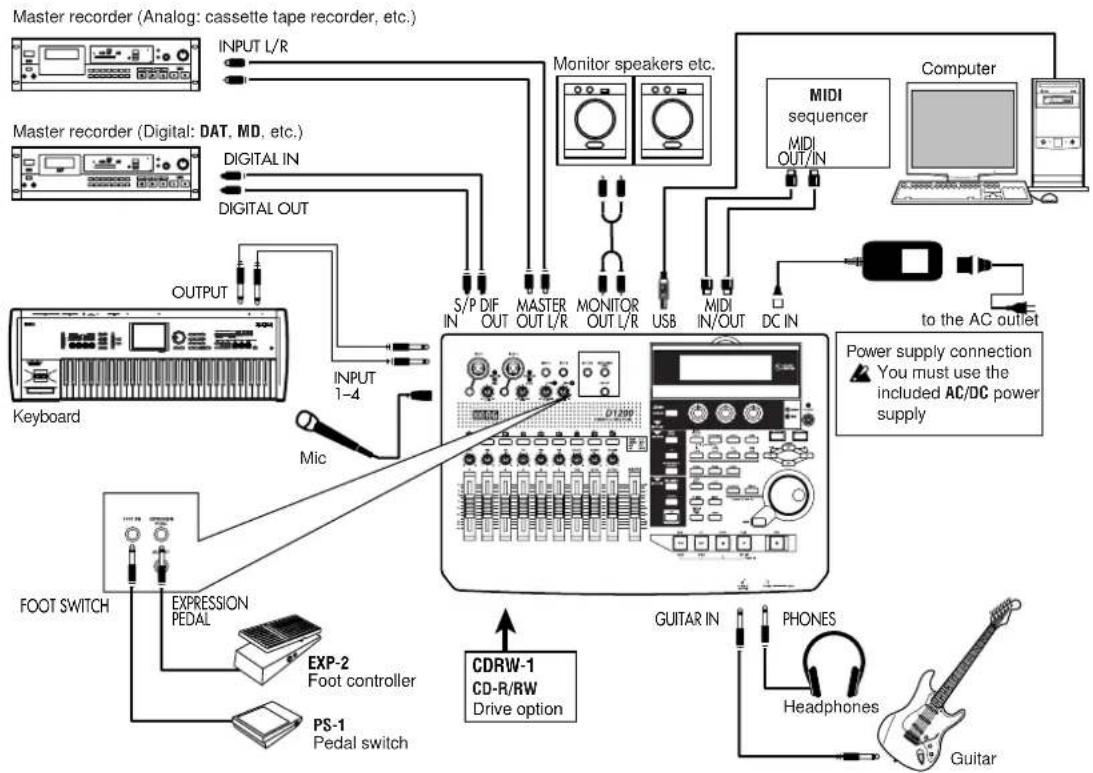
Here are some examples of basic connections for recording with the D1200. As necessary, substitute the equipment you are using for the devices named here.
CDRW-1 connections
For details on installing the CDRW-1 CD-R/RW drive option, refer to p.149.

You must make all connections with the power turned off. Making connections with the power turned on may damage your speaker system or cause malfunctions.
1-1. Output (audio output) connections
In order to hear the sounds recorded on the D1200, you will need to connect it to a monitor speakers (speakers with an internal amp) or other audio equipment, or use headphones.
Connecting audio equipment for monitoring
- Use RCA phono cables to connect monitor speakers to the [MONITOR OUT L/R] jacks.
- If you will use headphones for monitoring, connect your headphones (with a phone plug) to the [PHONES] jack. Use the [PHONES LEVEL] knob to adjust the volume.

The audio signal that is output from the [MONITOR OUT L/R] jacks and the [PHONES] jack can be selected in the [INPUT/OUTPUT/SOLO] "Monitor" tab page. (→p.100)
1-2. Input (audio input) connections
The D1200 has four channels of analog input and one (two-channel) digital input jack.
Connecting a guitar
• Guitar or bass guitar ↔ [GUITAR IN] jack
Connecting a mic
- Mic (XLR) [INPUT 1], [INPUT 2], phantom power
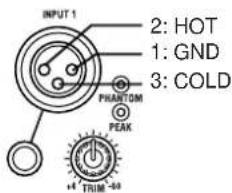
Connecting a keyboard
- Synthesizer etc. [INPUT 1]-[INPUT 4] jacks
Connecting audio devices
- Sub input For details on how to specify the mixer channel to which the input audio will be sent, and how to audition the input signal, refer to p.22.
- A guitar or bass guitar routed through a compact effects device can be connected to the [INPUT 1]–[INPUT 4] jacks.
- If you want to use a stereo input, select two adjacent inputs (1–2 or 3–4) so that you can perform track editing more efficiently.

If you are recording from a mic, place the mic sufficiently far from the D1200 so that it does not pick up noise.
Connections for digital recording
- Digital output jack of a DAT or MD with an optical digital (S/P DIF) output [S/P DIF IN] of the D1200 (use an optical digital cable for connections)

For details on how to specify the mixer channel to which the input audio will be sent, and how to audition the input signal, refer to p.35.
flowchart
graph TD
    A["Master recorder (Analog: cassette tape recorder, etc.)"] --> B["INPUT L/R"]
    C["Master recorder (Digital: DAT, MD, etc.)"] --> D["DIGITAL IN"]
    C --> E["DIGITAL OUT"]
    F["Keyboard"] --> G["OUTPUT"]
    G --> H["INPUT 1-4"]
    H --> I["Mic"]
    I --> J["FOOT SWITCH"]
    J --> K["EXPRESSION PEDAL"]
    K --> L["EXP-2 Foot controller"]
    L --> M["PS-1 Pedal switch"]
    M --> N["CDRW-1 CD-R/RW Drive option"]
    O["Computer"] --> P["MIDI sequencer"]
    P --> Q["MDI OUT/IN"]
    Q --> R["DC IN"]
    R --> S["to the AC outlet"]
    T["Guitar"] --> U["Headphones"]
    U --> V["Guitar"]
    W["Power supply connection ▲ You must use the included AC/DC power supply"] --> X["MONITOR OUT L/R"]
    X --> Y["USB"]
    Y --> Z["MIDI IN/OUT"]
    Z --> AA["DC IN"]
    AA --> AB["MIDI sequencer"]
    AB --> AC["Computer"]
1-3. Connections when using external recording devices
Here are the connections for recording your song onto an external device (DAT, MD, tape recorder, etc.).
- Optical digital (S/P DIF) input jack of a DAT or MD [S/P DIF OUT] of the D1200 (use an optical digital cable for connections)
- AUX IN jacks of a cassette tape recorder or other analog recording device [MASTER OUT L/R] jacks of the D1200
1-4. Connections when using an external effect
If you apply an external effect to the signal that is sent from the [AUX OUT] jack, connect the return from the effect unit to the [INPUT 1]-[INPUT 4] jacks.
Note: You can select whether the effect will be returned to the mixer channels in the same way as for conventional inputs, or sent directly to the master bus. ( p.45)
1-5. Pedal connections
Using a pedal switch to perform manual punch recording or play/stop operations
Connect a pedal switch (separately sold option: PS-1) to the [FOOT SWITCH] jack.
Using a foot pedal to control an effect
Connect an expression pedal (separately sold option: EXP-2, XVP-10) to the [EXPRESSION PEDAL] jack.
A volume pedal will not function correctly even if connected.
1-6. MIDI connections
Controlling effects or switching scenes from an external MIDI device
- MIDI OUT connector of the external MIDI device [MIDI IN] connector of the D1200 ( p.79)
Synchronizing the D1200 with a MIDI sequencer etc.
- MIDI IN connector of your sequencer [MIDI OUT] connector of the D1200 (use a MIDI cable for connections)
- MIDI OUT connector of your sequencer [MIDI IN] connector of the D1200 ( p.79)
1-7. USB connections
Save or backup data on your pc
- Your PC's USB connector the D1200's [USB] connector (use a USB cable for connections) ( p.77)
2. Turning the power on/off
2-1. Connecting the power supply
① Connect the included AC/DC power.
Connect the included power cable to the AC/DC power supply.
② Plug the power cable from the AC/DC power supply into an AC outlet.
2-2. Turning the power on
Follow this procedure to turn on the power of the D1200 and each connected device.
Note Before you turn on the power, be sure to set the volume of each device to the minimum position, and turn on the power switches starting with the "upstream" devices that output the audio signal.
① Lower the D1200's [MASTER] fader to - .
Lower the volume on external devices to the minimum position.
② Turn on the power of external input devices, such as a keyboard that sends an audio signal to the D1200.
③ Press the [POWER] switch of the D1200 to turn on the power.
The display will show the opening message. Then the [SONG] "SelSong" tab page will appear.
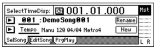
Note The song number that had been selected when you turned off the power will be selected.
④ Turn on the power of external output devices such as the monitor system to which the audio from the D1200 is being sent.
2-3. Turning the power off
Turn off the power when you are finished all operations such as song playback and recording. Use the following procedure to turn off the power of the D1200 and of each connected device.
Never disconnect the AC/DC power supply until the power has been turned completely off. Doing so may cause data to be lost.
Note When turning the power off, set the volume of all devices to the minimum position, and turn off the power switches starting with the "downstream" devices to which the audio signal is being sent.
Note Audio that you record on the D1200 and mixer settings etc. that you make are saved automatically when you select or change songs, or when you turn off the power. However, effect settings you edit outside of Modeling mode will be lost if you turn off the power without saving them.
① If you want to keep the effect settings you edited outside of Modeling mode, save them ( p.43).
② Lower the [MASTER] fader of the D1200 to - . Set the volume of externally connected device to the minimum position.
③ Turn off the power of devices such as a monitor system or MD recorder to which the audio from the D1200 is being sent.
④ Press and hold the D1200's [POWER] key until the power-off confirmation dialog box appears. If you press the [YES/OK] key, the song will be saved automatically, and then the power will be turned off. If you press the [NO/CANCEL] key, you will return to the previous screen.
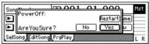
⑤ Turn off the power of external input devices such as keyboards.
The Restart function
In the power-off confirmation dialog box, you can select the "Restart" button and press the [ENTER] key to restart the D1200. This clears the Undo data in order to recover hard disk capacity.
3. Display
3-1. Adjusting the angle
You can lift the upper part of the display to adjust the angle. Adjust the angle for easiest viewing.
To adjust the angle
Raise the upper part of the display to adjust the angle.

Do not use excessive force to move this.
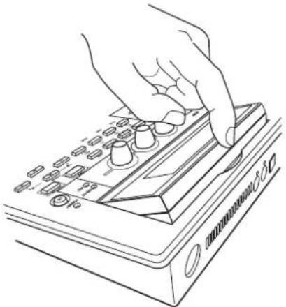
natural_image
Line drawing of a hand pressing down on a handheld electronic device with buttons and a scroll (no text or symbols)3-2. Adjusting the contrast
The readability of the screen will depend on the height of your line of sight or the temperature, so adjust the contrast as necessary.
To adjust the contrast
A combination of [CURSOR] keys is used to adjust the contrast. UP+LEFT: Hold the CURSOR [UP] key and press the [LEFT] key to make the characters lighter. UP+RIGHT: Hold the CURSOR [UP] key and press the [RIGHT] key to make the characters darker.
Listening to the demo song
When the D1200 is shipped from the factory, it contains several demo songs.
Here's how to listen to these demo songs.
① Set the D1200's [CHANNEL] faders to the 0 mark, and the [MASTER] fader to - . Connect your headphones.
② Turn on the power.
③ Select the song that you want to play.
④ Set the [TRACK STATUS] keys of all tracks so that the LEDs are lit green. If it is lit a different color, or is dark, press the key to make it light green (PLAY).
⑤ Press the [PLAY] key to begin playback.
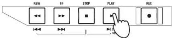
⑥ Slowly raise the [MASTER] fader to adjust the volume level. While the song plays, adjust the [CHANNEL] faders, [PAN] knobs, and EQ, and change the program for the insert effect, and master to hear the result.
⑦ When the demo song ends, press the [STOP] key to stop playback.
Demo song list
The Game
Written and performed by Insex In Amber Ted Burger — Guitars, Bass Jack Bielata — Vocals Steve Michael — Drums
© 2000 Ted Burger, Jack Bielata All Rights Reserved www.insexinamber.com
Play The Blues
Written and performed by Nomura Daisuke.
© 2002 KORG Inc. — all rights reserved.
Quick Start Tutorial
This Quick Start Tutorial is designed to familiarize you with many of the features of the D1200, as well as with the many recording procedures that can be performed using the D1200. While the Operation and Reference sections of this manual will explain every feature and control in great detail, this step-by-step tutorial will allow you to "learn by doing" as we take you through the entire process, from recording your first track to mastering a CD.
Step 1: Quick recording
Connect your guitar, record your performance on tracks 1 and 2, and play it back.
Step 2: Overdubbing
While listening to the guitar performance that you recorded in step 1, connect a keyboard and record (overdub) your performance on tracks 9 and 10. Then record a vocal on track 3.
Step 3. Mixing
Apply effects to each track, and adjust the volume and EQ. Use the master effects to apply effects to the entire song while you mix.
Step 4. Mastering
Create a two-track master track from the song that you mixed-down in Step 3. Write the master track to CD-R to create your own original CD.
Step 1: Quick recording
1. Getting ready
If you will be using the separately sold CDRW-1, refer to "About the CDRW-1" (→ p.149) and install the CDRW-1 before you continue with the steps below.
① Connect your guitar.
Set the INPUT 1 [TRIM] knob to the minimum position, and connect your guitar to the [GUITAR IN] jack.
② Connect your headphones to the [PHONES] jack.
2. Turning on the power
① Connect the AC/DC power supply. Connect the included AC/DC power supply to the [DC IN] jack. Connect the included power cable to the AC/DC power supply. Connect the power cable to an electrical outlet.
② Set the [MASTER] fader to the “ - ” position.
③ Press the [POWER] key to turn on the power.

Connection diagram (→p.14)
Turning the power on (→p.15)
3. Creating a new song
In order to begin recording, you must first create a new blank song.
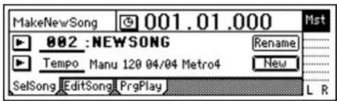
① Press the [SONG] key to access the "SelSong" tab page.

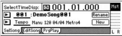
② Use the [CURSOR] keys to select the "New" button, and press the [ENTER] key. The "MakeNewSong" dialog box will appear.
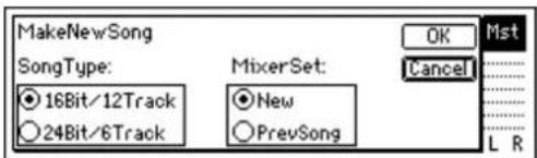
③ Specify the bit depth/number of tracks and the mixer settings for the song that will be created.
Use the "SongType" buttons to select the bit depth and number of tracks, and press the [ENTER] key. Select the "MixerSet" setting in the same way. For this example, select "16Bit/12Track" and "New."
④ Press the [YES/OK] key. A new empty song named "NEWSONG" will be created
4. Using the modeling mode
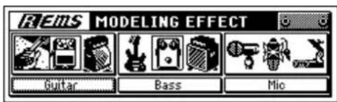
① Press the [MODELING] key, select "Guitar" from the three categories, and press the [ENTER] key. The LEDs of the [MODELING] key and the CH 1 and 2 [TRACK STATUS] keys will light red.
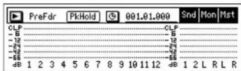
② Check the input level. Press the [METER/TRACK VIEW] key.

"SongType," "MixerSet" (→p.116)
Editing the song name ( p.31)
Modeling mode (→p.45)
Select the "button and press the [ENTER] key to open the dialog box.
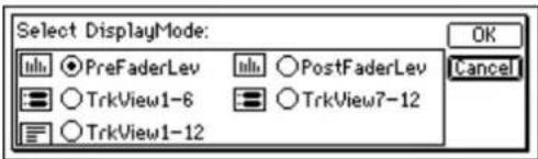
Select the "PreFaderLev" radio button, press the [ENTER] key, and then press the [YES/OK] key.
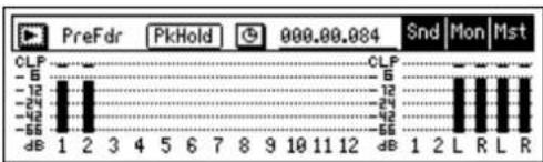
③ As you play your guitar, watch the Ch1 and Ch2 meters and adjust the INPUT 1 [TRIM] knob. You will not be hearing the guitar signal at this point.
bar
| Time (s) | CLP | | :--- | :--- | | 1 | -12 | | 2 | -24 | | 3 | -42 | | 4 | -56 | | 5 | -12 | | 6 | 24 | | 7 | 42 | | 8 | 10 | | 9 | 11 | | 10 | 12 | | 11 | 12 | | 12 | 12 | | 1 | 2 | | 2 | L | | 3 | R | | 4 | L | | 5 | R |Adjust the level as high as possible without allowing the level meter's "CLP" indicator to light when you play most strongly. In general, you should adjust the [TRIM] knob so that the peak indicator (the LED near the [TRIM] knob) lights when you play your loudest passage.
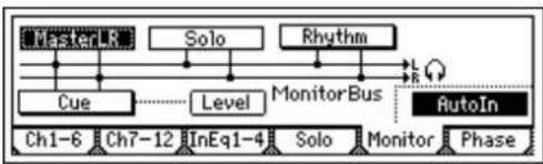
④ Now, let's listen to the audio signal. Set the [CHANNEL 1] and [CHANNEL 2] faders to unity gain (0 dB). Access the [INPUT/OUTPUT/SOLO] "Monitor" tab page.
flowchart
graph TD
    A["MasterLR"] --> B["Solo"]
    B --> C["Rhythm"]
    C --> D["AutoIn"]
    D --> E["Cue"]
    E --> F["Level"]
    F --> G["MonitorBus"]
    G --> H["Ch1-6"]
    G --> I["Ch7-12"]
    G --> J["InEq1-4"]
    G --> K["Solo"]
    G --> L["Monitor"]
    G --> M["Phase"]
Select the "MasterLR" button and press the [ENTER] key to turn it "On" (highlighted). Slowly raise the [MASTER] fader, and make sure that you hear the sound of your guitar from the headphones.
⑤ Dial up your settings for the modeling effects. Return to the Modeling mode page either by pressing the [MODELING] key. While you listen to the sound in your headphones or monitors, use the three modeling knobs to adjust the "DRIVE," "TONE," and "CABINET" settings to obtain the desired sound.
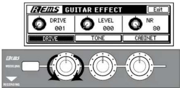
Use the [PHONES LEVEL] knob or the [MONITOR OUT LEVEL] knob to adjust the output volume.
To allow a stereo effect to be heard in stereo, turn the [PAN1] knob to the far left and the [PAN2] knob to the far right.
To tune your guitar ( p.36: Using the tuner)
5. Setting up a rhythm
Here's how to make rhythm settings so that you can listen to a rhythm pattern while you record.
① Press the [RHYTHM] key.
In the [RHYTHM] "Setup" tab page, turn the "Rhythm" button "On" (highlighted).
The [RHYTHM] key will light. Raise the [MASTER] fader and you will hear the rhythm.
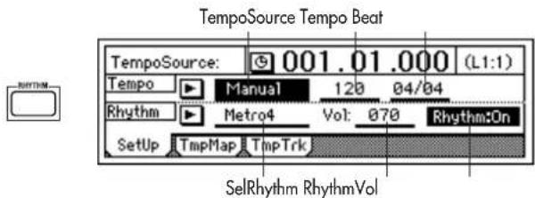
② Specify the tempo, time signature, and rhythm pattern.
Select "TempoSource," and select the tempo source.
For this example, choose "Manual." The same tempo, time signature, and rhythm pattern will be used throughout the song.
Select "Tempo," and turn the [VALUE] dial to adjust the tempo.
Select "Beat," and turn the [VALUE] dial to specify the time signature.
Select "SelRhythm," and turn the [VALUE] dial to select a rhythm pattern.
Select "Vol," and turn the [VALUE] dial to adjust the rhythm volume.
6. Recording
① Access the track view screen so you can view the status of the recording tracks.
Press the [METER/TRACK VIEW] key, select the "button, and press the [ENTER] key to open the dialog box.
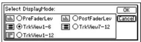
In "SelectDisplayMode," select the "TrkView1-6" radio button and press the [ENTER] key. Then press the [YES/OK] key.
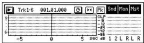
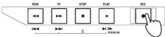
② Press the [REC] key to enter record-ready mode. The [REC] and [PLAY] LEDs will blink.
If you want the tempo, time signature, and rhythm pattern to change during the song, you will need to create tempo maps. (→p.49)
Trigger recording (→p.54)
Recording the rhythm (→p.48)
③ When you are ready to perform, press the [PLAY] key.
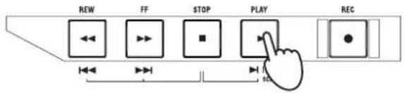
The [REC] and [PLAY] LEDs will light.
When recording starts, begin performing.
You will hear the rhythm pattern you selected. Go ahead and play along.
④ When you have finished playing, press the [STOP] key.
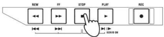
Recording will stop, and the [REC] and [PLAY] LEDs will go dark. In the track view screen, a heavy line will indicate the region that you recorded.
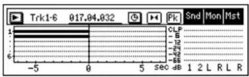
7. Play back
Now let's play back the song you just recorded.
① Press the track 1 and 2 [TRACK STATUS] keys to set them to PLAY (LED lit green).
② While holding down the [STOP] key, tap the [REW] key. The counter display will move to the beginning of the song.
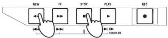
③ Press the [PLAY] key to begin playback. During playback, the [PLAY] LED will light green. Use the [MASTER] fader to adjust the volume.
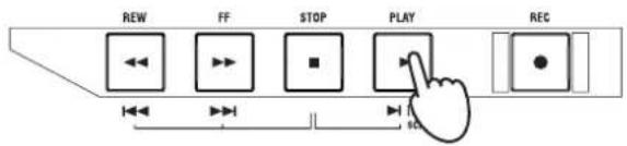
④ Press the [STOP] key. Playback will stop, and the [PLAY] LED will go dark.
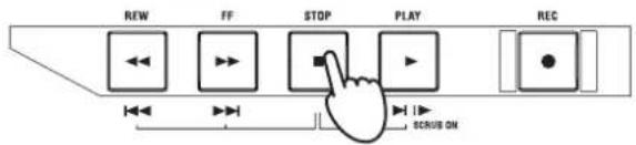
To stop the rhythm
In the [RHYTHM] "Setup" top panel, select the "Rhythm" button and press the [ENTER] key to turn it "Off."
The heavy line will appear even in sections where you were not actually playing your instrument.
Counter display, move to time ( p.32)
To exit Modeling mode (→p.47)
Step 2: Overdubbing
1. Assigning inputs to the mixer
In this section, you'll connect your keyboard to the [INPUT 3] and [INPUT 4] jacks, assign the signals to mixer channels 9 and 10, and record the signal on tracks 9 and 10.
① Set the INPUT 3 and INPUT 4 [TRIM] knobs to the minimum position (+4 dB), lower the [MASTER] fader, and connect your keyboard to the [INPUT 3] and [INPUT 4] jacks.
② Specify the input channels. Access the [INPUT/OUTPUT/SOLO] "Ch7-12" tab page. Select the "Ch9" icon, and use the [VALUE] dial to select "INPUT 3." In the same way, select the "Ch10" icon and use the [VALUE] dial to select "INPUT 4."
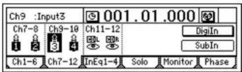
Using these settings, the [INPUT 3] and [INPUT 4] jacks will be assigned to mixer channels 9 and 10.
③ Press the track 9/10 [TRACK STATUS] key to select INPUT (LED lit orange).
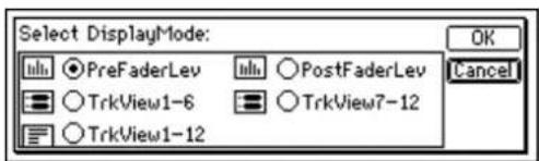
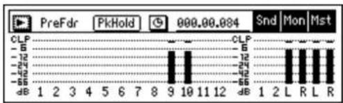
④ Use the [TRIM] knobs to adjust the input level. Press the [METER/TRACK VIEW] key. Select the "button and press the [ENTER] key to open the dialog box. Select "PreFaderLev," and press the [YES/OK] key.
bar
| Category | Value | |---|---| | CLP | 6 | | -5 | 12 | | -12 | 24 | | -24 | 42 | | -32 | 56 | | -55 | 10 | | dB | 1 2 L R L R |As you play the keyboard, watch the Ch9 and Ch10 levels and adjust the INPUT 3 and 4 [TRIM] knobs.
Set the levels as high as possible without allowing the level meters to reach "CLP" when you play the keyboard at your loudest level. In general, you should adjust the [TRIM] knob so that the peak indicator (the LED near the [TRIM] knob) lights when the maximum input level is reached.
⑤ Set the [CHANNEL 9–10] fader to unity gain (0 dB).
If you are using a stereo input source, it will be easier to edit track and effect settings if you select adjacent inputs (1–2 or 3–4), and route them to adjacent mixer channels.
Use the [PHONES LEVEL] knob or the [MONITOR OUT LEVEL] knob to adjust the output volume.
2. Applying an insert effect to the keyboard.
① Access the [INSERT EFFECT] "InsAss" tab page.
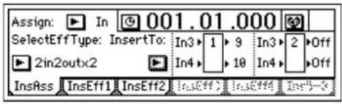
② Select the "Assign:" ▶"button and press the [ENTER] key to open the dialog box. Select "Input(In)" and press the [YES/OK] key.
③ Select the "SelectEffType:" ▶"button and press the [ENTER] key. Select the "2in2outx2" effect type (as shown in the screen in step 1) and press the [YES/OK] key.
④ Now we need to insert the effect between INPUT 3 and channel 9, and between INPUT 4 and channel 10.
Select the "InsertTo:" button and press the [ENTER] key.
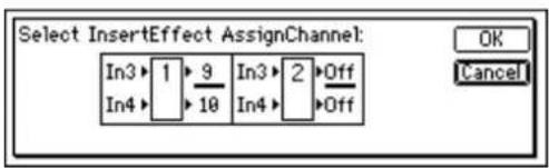
In the display, you will see the two insert effects shown as boxes labeled 1 and 2. The numbers to the left show which inputs are feeding the effect, the numbers to the right show to which channels the effect is being output.
Highlight the number to the upper right of effect 1. Turn the [VALUE] dial until the display shows In3 and In4 on the left and (channels) 9 and 10 on the right and press the [YES/OK] key.
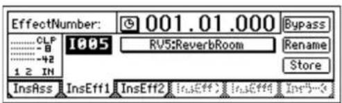
⑤ Select an effect program.
Access the [INSERT EFFECT] "InstEff1" tab page. Select "EffectNumber," and turn the [VALUE] dial to select an effect program. When you have made your selection, press the [YES/OK] key.
3. Overdubbing
① Select the playback tracks.
For each track that you want to play back, press the [TRACK STATUS] key to select PLAY (LED lit green). For this example, set tracks 1 and 2 to PLAY.
② Select the recording tracks.
For each track that you want to record, press the [TRACK STATUS] key to select REC (LED lit red). For this example, set tracks 9/10 to REC.
③ Mute the tracks you are not using.
For each track that is not being played or recorded, press the [TRACK STATUS] key to select MUTE (LED dark), so that you will not hear tracks that are not being recorded or played.
Effect Program List ( p.154)
④ In the [BOUNCE] "RecMode" tab page, make sure that "Select Rec Mode" is set to "Input."
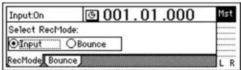
⑤ For this example, we will start recording from the beginning of the song ("001.01.000" or "000:00.000"). If you are not at the beginning, hold down the [STOP] key and tap the [REW] key to return to the beginning of the song.
⑥ Enter record-ready mode. Press the [REC] key (the [REC] and [PLAY] LEDs will blink).
⑦ Begin recording. Press the [PLAY] key (the [REC] and [PLAY] LEDs will light). Begin playing the keyboard.
⑧ Stop recording. When you have finished performing, press the [STOP] key (the [REC] and [PLAY] LEDs will go dark).
⑨ Listen to the overdub. Return to the beginning of the song. Press the track 9 and 10 [TRACK STATUS] keys to set them to PLAY (lit green). Press the [PLAY] key.
4. Overdubbing additional parts
Next we'll add a vocal on track 3.
① Connect a mic to the [INPUT 1] jack.
② Press the [MODELING] key to enter Modeling mode. Select "MIC" as the Modeling Category.
③ Set the track 3 [TRACK STATUS] to REC. When you enter Modeling mode, tracks 1 and 2 will be set to REC. Press the track 1 and 2 [TRACK STATUS] keys to set them to PLAY, and press the track 3 [TRACK STATUS] key to set it to REC.
④ Adjust the input level, recording level, and effects to prepare for recording.
⑤ Move to the location at which you want to start recording, and start recording. Press the [FF] key or [REW] key to move to the desired time location. Press the [REC] key and then the [PLAY] key to start recording. When you are done, press the [STOP] key.
⑥ Let's change virtual tracks to record another take. Press the [TRACK] key to access the "Vtr1-6" tab page.
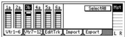
Select track "3a" and turn the [VALUE] dial to change it to "3b."
⑦ Move the location again, and begin recording. Move to the location from which you want to begin recording, and press the [REC] key and then the [PLAY] key to begin recording.
⑧ Play back track 3. Press the [TRACK STATUS] key to select PLAY, and press the [PLAY] key to play back. At this time, track "3b" will play back.
Counter display ( p.32)
When you have finished recording, check to be sure that your performance was recorded correctly.
Use phantom power if you have connected a condenser mic.
Move to time (→p.32)
Virtual tracks (→p.53)
If you want to play back a track that you have already recorded, set that track's [TRACK STATUS] to PLAY.
In order to play track "3a" which you recorded first, press the [TRACK] key, access the "Vtr1-6" tab page, select "3b," and turn the [VALUE] dial to change it to "3a."
Compare the two takes you recorded in virtual tracks "a" and "b." When you have decided which take is the best, leave that virtual track selected.
Step 3. Mixing
In this step you will complete your song by applying effects to the tracks and adjusting the volume and EQ to create the overall balance. This process is called "mixing."
1. Applying an insert effect to a track
Previously, we applied the insert effects to the inputs, to process the sound as we recorded. Here's how to apply an insert effect into a mixer channel, and process the playback sound of the track. In this example, we are assigning an insert effect to the vocal(Mic) recording on track 3.
① Select which tracks will be played back.
Press the [TRACK STATUS] key of each recorded track to select PLAY mode (LED lit green), the playback of the selected tracks will be included in the mix.
② Access the [INSERT EFFECT] "InsAss" tab page.
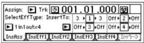
③ Select the "Assign:" button and press the [ENTER] key. In the dialog box that appears, select "PlayTrack(Trk)."
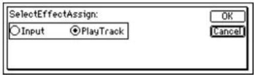
When you have made your selection, press the [YES/OK] key.
④ Select the "SelectEffType:" button and press the [ENTER] key to select the effect type.
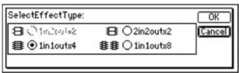
For this example, select "1in1outx4." Make your selection, and press the [YES/OK] key.
To exit Modeling mode ( p.47)
Effect types ( p.42, 85)
⑤ Specify the channel where you want to insert the effect. Select the "InsertTo:" button, and press the [ENTER] key to open the dialog box.
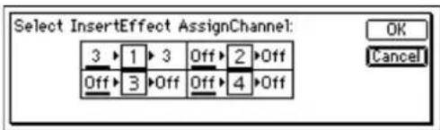
For each effect, turn the [VALUE] dial at "SelectCh" to select the input (output) channel. For this example, set effect 1 to channel "3." When you have made the setting, press the [YES/OK] key.
⑥ Select an effect program. In the insert effect "InsEff1" tab page, select the effect program that you want to use. Select "EffectNumber," and turn the [VALUE] dial to select an effect program.
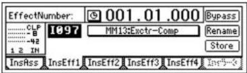
⑦ Press the [PLAY] key to begin playback. You can also select an effect program while you listen to the play-back.
2. Adding EQ (equalization) to each track
① Press the [EQ] key. Select the [EQ] "EQ1-4," "Eq5-8," or "Eq9-12" tab page that contains the EQ settings you want to adjust.
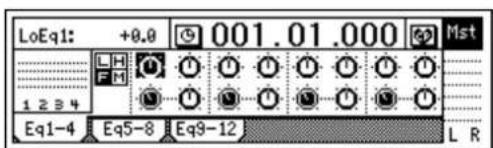
② Select the EQ you want to adjust. The following EQ controls are provided for each channel.
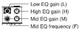
③ Adjust the gain and frequency. Adjusting the gain in the “−” direction will cut the sound, and in the “+” direction will boost the sound. Raising the mid EQ frequency setting will cause the mid-range boost/cut to affect a higher frequency range. Lowering it will cause the boost/cut to affect a lower frequency range. ④ Press the [PLAY] key to start playback. You can also adjust the EQ while you listen to the playback.
EQ ( p.37, 88)
3. Applying master effects to several tracks
Here we will select several tracks, and apply master effects to them. The D1200 contains two master effects. By combining two different effects you can simulate complex spatial environments that could not be produced by a single effect alone.
For example you could apply "RV1:ReverbHall" to master effect 1 and "RV5:ReverbRoom" to master effect 2, so that you can vary the character of the reverb applied to each instrument by adjusting the two send levels on each channel.
In this way, you can use two different effects in conjunction with each other to create complex spatial-type effects that could not be achieved by a single effect.
① Press the [MASTER EFFECT/AUX SEND] key to access the [MASTER EFFECT/AUX SEND] "MstEff1" tab page.
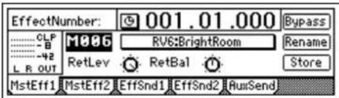
② Select an effect program.
Select "EffectNumber," and turn the [VALUE] dial to select an effect program.
③ Set the return level and return balance of the signal that is sent from the master effect to master LR.
For this example, set "RetLev" (return level) to "100," and "RetBal" (return balance) to "CNT" (center).
④ Adjust the send levels.
The send levels from each channel to master effect 1 can be adjusted in the "EffSnd1" tab page.
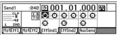
Select each "Send" icon knob, and turn the [VALUE] dial to adjust the send levels.
In this example, we will apply master effect 1 to tracks 1, 2, and 9/10.
⑤ Press the [PLAY] key to start playback.
While the song plays, listen to the master LR output and hear the effects that are applied.
Adjust the return level and the send levels so that the master effect level meters do not indicate "CLP."
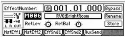
To apply master effect 2, make similar adjustments in the "MstEff2" and "EffSnd2" tab pages.
Effect Program List (→p.154)
Step 4. Mastering
In this step, we create a final two-track mix and write it to CD-R to create an original CD.
Note You will need the separately sold CDRW-1 in order to create a CD.
1. Applying the final effect
Here we will adjust the pan and volume for each track, and apply a final effect to the entire song.
The final effect is used mainly to apply a dynamics-type effect such as a compressor, to make the overall level more consistent. You can apply an effect such as a multi-band limiter to add the finishing touch to the sound.
① Adjust the pan of each playback track.
Press the [PLAY] key to play back the song, and turn the [PAN] and [BALANCE] knobs to adjust the stereo position of tracks 1–12.
② Use the [CHANNEL] faders to adjust the playback level. Press the [METER/TRACK VIEW] key to view the level meters. Select the "button and press the [ENTER] key to open the dialog box. Select "PostFaderLev" to view the meters corresponding to each fader.
③ Access the [FINAL EFFECT] "FinalEff" tab page.
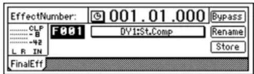
④ Select an effect program. Select "EffectNumber," and use the [VALUE] dial to select an effect program. Press the [PLAY] key to play back the song, and listen to the output from the master LR or headphones to hear the effect. When you have finished making adjustments, press the [STOP] key.
2. Creating the master track
In order to create an audio CD from a multi-track song, you will need to combine the tracks into two tracks of data.
Here we will bounce-record the completed song, creating a stereo master mix on tracks 1 and 2.
① Use the [MASTER] fader to adjust the recording level.
Play back the entire song, and adjust the [MASTER] fader so that the "CLP" indication does not appear for the master LR level meter.
② Select the tracks where the master mix will be recorded.
For the tracks that you will record (tracks 1 and 2), set the [TRACK STATUS] keys to REC. Set the remaining tracks (3–12) to PLAY.
③ Select bounce-recording as the recording mode.
Press the [BOUNCE] key to access the [BOUNCE] "RecMode" tab page, and set "Select RecMode" to "Bounce."
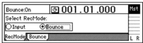
④ Select the bounce mode.
Access the [BOUNCE] "Bounce" tab page, and select "12Tr→2Tr" as the "BounceMode."
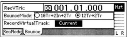
⑤ Set "RecordVirtualTrack" to specify the virtual tracks (of the record tracks) on which you will record.
If you want to record on the currently selected virtual tracks, select "Current."
⑥ Move the current location to the beginning of the song. (→p.32)
⑦ Begin bounce-recording.
Press the [REC] key to enter record-ready mode (LED blinking), and press the [PLAY] key to begin recording (LED lit).
When you are finished recording, press the [STOP] key to stop.
⑧ Check the recorded content.
Press the [TRACK STATUS] keys of the recording tracks (1 and 2) to select PLAY mode.
For the remaining tracks 3–12, either lower the faders to the minimum position or set their [TRACK STATUS] keys to MUTE.
Return to the beginning of the song and press the [PLAY] key to hear the results. Press the [STOP] key to stop.
3. Writing to CD
Finally we will use the CD-R/RW drive to create an original CD of the song you just recorded. Press the [CD] key to access the "Prepare" tab page.
① First, let's select the two tracks you bounce-recorded, and use Track Monitor to listen to them.
In "SelTrks," select the master tracks to which you bounce-recorded your mix. For this example, select "1–2."
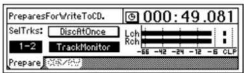
Turn "TrackMonitor" on, and press the [PLAY] key.
You will hear tracks 1 and 2 which you selected in "SelTrks."
② Insert a commercially-available blank CD-R disc into the CDRW-1.
③ Access the [CD] "CDR/RW" tab page.
Make sure that "CD-R/RW Information" indicates "BlankDisc."
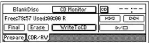
④ Write to CD.
Select the "WriteToCD" button and press the [ENTER] key.
Select the writing speed. For this example, select "8X." The disc will be written at 8X speed.
If you select "Current," your mix will be recorded on the same virtual tracks as were played back. If you want to keep the data of those virtual tracks after bounce-recording, you must select virtual tracks other than "Current."
In order to create an audio CD, the D1200's internal hard disk must have as much free space as is occupied by the song (the two-channel total) you are creating. For example in order to create an audio CD of a five-minute song, you must have enough free space to accommodate ten minutes of monaural recording.
If the song you write to CD has no silence at the beginning (i.e., at time "zero"), you may not hear the very beginning of the song when the CD is played back. In such cases, insert about half a second of silence at the beginning ("zero" time) of the two-track mix. p.58: "InsertTrack")
If you leave "TrackMonitor" turned on, you can monitor the playback without EQ or effects being applied.
Since some audio CD players will not play CD-RW discs, we recommend that you use CD-R discs to create audio CDs.
The "Obey Copyright Rules" message will appear.
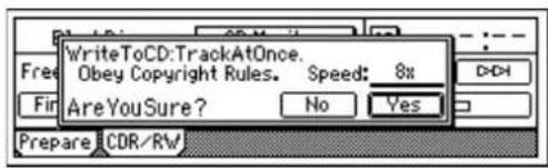
Carefully read the section "COPYRIGHT WARNING" (→p.1) in the owner's manual, and press the [YES/OK] key if you accept the terms.
Writing to disc will begin.
When writing is finished, the display will indicate "Completed." Press the [NO/CANCEL] key.
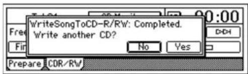
⑤ If you want to write another song, select a song then use steps ①-④ to write additional songs.
⑥ Finalize the disc.
If you want to be able to play back the disc, select the "Final" button and press the [ENTER] key to finalize the disc.
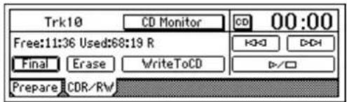
A message will ask you to confirm the operation. If you are sure that you want to finalize the disc, press the [YES/OK] key.
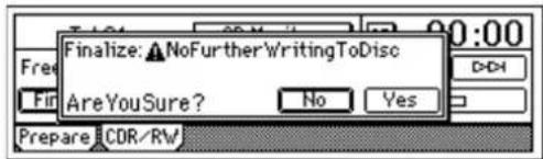
When finalization is completed, the "Completed" message will appear, and the CDRW-1 tray will open. Press the [YES/OK] key.
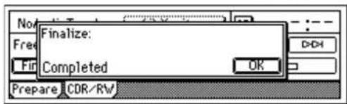
⑦ Play back the disc on an audio CD player to verify that it plays correctly.
You and your Korg D1200 have now created an original CD of your own performance!
While the disc is being written, you can select the "Abort" button and press the [ENTER] key to abort the writing process. However, this will produce an incomplete disc.
If you want to create another CD with the identical contents, press the [YES/OK] key.
No further songs can be written to a disc that has been finalized. Finalize the disc only after you have written all the songs you intend to write to that disc.
Operation
Song and Locate
1. Creating, naming and selecting songs
This section will cover how to create a song, how to name a new or existing song, and how to select an existing song. The D1200 has 100 song locations.
1-1. Creating a new song
Before you begin recording, you will need to create a new song where the recording will take place.
① Press the [SONG] key to access the "SelSong" tab page.
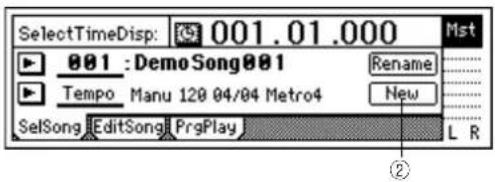
② Use the [CURSOR] keys to select the "New" button, and press the [ENTER] key. The "MakeNewSong" dialog box will appear.
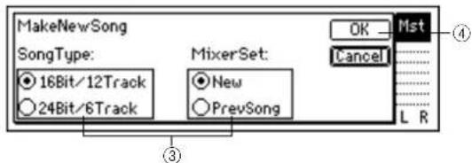
③ Use the radio buttons to select the bit depth (which will determine the number of tracks), and the mixer settings. Then press the [ENTER] key. Use the "SongType" radio buttons to select the bit depth and number of tracks, and press the [ENTER] key to make the setting. 16Bit/12Track: A song using 16-bit recording/playback will be created. Tracks 1-12 are available in this mode. 24Bit/6Track: A song using 24-bit recording/playback will be created. Tracks 1-6 are available in this mode. Select the desired "MixerSet" radio button in the same way. (→p.116)
④ Press the [YES/OK] key. A song named "NEWSONG" will be created following the last existing song.
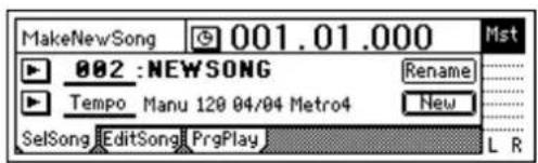
1-2. Editing the name of a song
Songs on the D1200 are designated by name. Song names can be up to 16 characters in length. The D1200 contains 100 locations for songs, numbered 001–100. Songs are assigned to these numbered locations in the order they are created. Both the song names and the order number can be freely edited.
Note By default, each newly created song will be named "NEW SONG." So that you will be able to distinguish it from other songs, we recommend that you assign a name to your song before you continue.
① Press the [SONG] key to access the "SelSong" tab page. If you want to edit the name of a different song, select that song first (→"1-3. Selecting different songs").
② Use the [CURSOR] keys to select the "Rename" button, and press the [ENTER] key.
The "RenameSong" dialog box will appear.
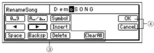
③ Edit the song name.
Use the "◀" buttons to move the cursor. Then turn the [VALUE] dial to edit the character.
The buttons in the display have the following function. "0...9": Selects numerals (e.g., "0")
"A../a..": Selects alphabetical characters (e.g., "A"). Press this button again to select lowercase alphabetical characters (e.g., "a").
"Symbol": Selects symbols.
"Insert": Inserts a space, moving subsequent characters backward.
"Space": Selects a space (blank).
"Backsp": Deletes the character that precedes the cursor location.
"Delete": Deletes the character at the cursor location. "ClearAll": Erases the entire name.
④ Finalize the changes.
If you are satisfied with the name you have made, press the [YES/OK] key. If you decide not to change the name, press the [NO/CANCEL] key.
1-3. Selecting different songs
There are three ways to select an existing song.
To select a song from the preceding or following song location
- Hold down the [STOP] key and tap the [FF] key to move to the end of the current song. Tap the key once again to move to the beginning of the next song.
- Hold down the [STOP] key and tap the [REW] key to move to the beginning of the current song. Tap the key once again to move to the beginning of the previous song. If you are already at the beginning of the current song (e.g., "001.01.000") holding down the [STOP] key and tapping the [REW] key once will locate the beginning of the previous song.
To select a song in a non-adjacent location
① Press the [SONG] key to access the "SelSong" tab page.
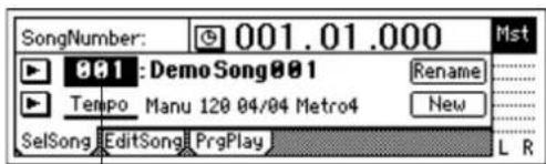
②
② Move the cursor to "SongNumber," and turn the [VALUE] dial to select a song number.
To select a song from the song list
① Press the [SONG] key to access the "SelSong" tab page.
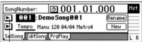
②
② Select the ▼ button located at the left of the song number, and press the [ENTER] key. The song list will appear.
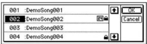
③ Turn the [VALUE] dial or use the 📋 buttons to select a song, press the [ENTER] key, and then press the [YES/OK] key.
2. Using the counter display
The counter indicates the current location within the selected song. You can use the counter to program in and out points, to "mark" locations, and to pinpoint an exact location when using the "scrub" function.
2-1. Switching the counter display
You can select the type of units that the counter will use to display the current location.
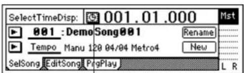
①
① Select the "button at the left of the counter, and press the [ENTER] key to access the "Select Time Disp Type" dialog box.
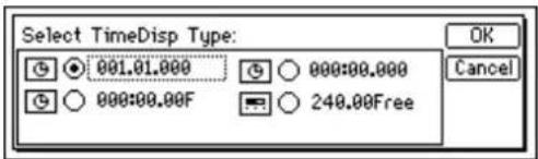
② Select a location display method and press the [YES/OK] key.
You can choose from the following four methods.
- ____. "measures", "beats", "1/96th beats"
- __:__._ "minutes", "seconds", "1/1000th seconds"
- __:__F"minutes","seconds","1/30 seconds"
- ____. Free "minutes"."seconds" (remaining amount of recording time)
To check the remaining recording time
Access the "Select Time Disp Type" dialog box, and choose "_. Free."
To determine the correct “____Free” time, set [TRACK STATUS] to REC for all the tracks that you want to record. The display will indicate the recording time that is available for recording on each track that is set to REC.
2-2. Changing the current location
Using the counter to move to a new location
① Select a page in which the upper part of the display shows the counter, such as the [SONG] "SelSong" tab page.
② In the counter, select the time field (e.g., measures, minutes, seconds) that you want to change.
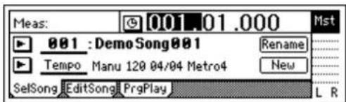
③ Turn the [VALUE] dial to move the current location.
Using [FF] and [REW] to move to a new location
Moving backward
Press the [REW] key to move backward in the song. You will move continuously if you keep holding [REW] down.
You may also use this method to move during playback.
Moving forward
Press the [FF] key to move forward in the song. You will move continuously if you keep holding [FF] down.
You may also use this method to move during playback.
Moving to the beginning of the song
If you are currently not at the beginning of the song, hold down the [STOP] key and press the [REW] key to move to the beginning of the song.
Moving to the end of the song
If you are currently not at the end of the song, hold down the [STOP] key and press the [FF] key to move to the end of the song.
Using the Locate keys
You can register a specific location in one of the Locate keys, and then jump instantly to that location.
You can register four locate points in each song using the [IN/LOC1], [OUT/LOC2], [TO/LOC3], and [END/LOC4] keys.

In addition to recalling the registered locate points, these keys are also used to specify the auto-punch recording times (IN/OUT) and the region for track editing. For details on the Locate functions, refer to p.118.
Registering a location to one of the Locate keys
① Use the counter ("Counter") or the [FF]/[REW] keys to move to the location you want to register.
② Press the [STORE] key to memorize the location you selected.
![StoredTime:007.01.000 Press[LOC..],[MARK]or[SCENE]](/content/2026/05/820878/images/89e2fef26d9c2af65055f35a4238bcc9c9843295405005bf0b00ef7a295363c7.jpg)
③ Press either the [IN/LOC1], [OUT/LOC2], [TO/LOC3], or [END/LOC4] key to register the memorized location to that key. The registration is completed as soon as you press the key.
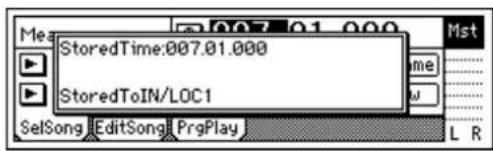

Even while the song is playing or recording, you can memorize the location by pressing the [STORE] key, and register it to one of the Locate keys.
Moving to a registered Locate time
When you press any of the [IN/LOC1], [OUT/LOC2], [TO/LOC3], or [END/LOC4] keys you will immediately move to the location registered to that key
Using a Mark to move to a new location in the song
You can register up to 100 marks at desired locations throughout your song, and jump instantly to a registered mark.
You can give a name to each mark, and use it to remember a certain place within the song.
Up to 100 marks can be registered in each song.
Registering a mark
① Move to the location where you want to register a mark. Use the counter or the [FF]/[REW] keys to move.
② Press the [STORE] key to memorize the current location.
![StoredTime:007.01.000 Press[LOC..],[MARK]or[SCENE]](/content/2026/05/820878/images/b92abf448f07fe8255c0dbe5088cf731eb5da437479ad274266267b2a07c1942.jpg)
③ Press the [MARK] key to register a mark at the memorized location. Registration is completed as soon as you press the key. Marks are automatically renumbered according to their playback order.
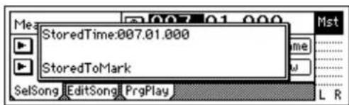

Even while the song is playing or recording, you can memorize the current location and register it as a mark. (The time at which you pressed the [STORE] key will be registered.)
Moving to a registered Mark time
① Access the [MARK] "Mark" tab page.
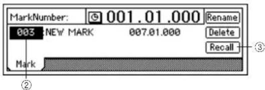
② Use "MarkNumber" to select a mark.
③ Select the "Recall" button and press the [ENTER] key to recall the mark.
You will move to the location of that mark.
Deleting a mark

A mark you deleted cannot be recovered by Undo.
① Access the [MARK] "Mark" tab page.
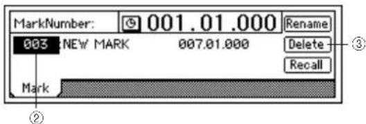
② Use "MarkNumber" to select the mark that you want to delete.
③ Select the "Delete" button and press the [ENTER] key to open the dialog box.
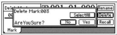
④ Verify that "Delete Mark" in the upper left indicates the mark you want to delete, and press the [YES/OK] key to delete the mark. If you decide not to delete the mark, press the [NO/CANCEL] key.
If you want to delete all marks, select the "SelectAll" button and press the [ENTER] key. Then press the [YES/OK] key to delete all the marks.
Naming a mark
- Select the "Rename" button and press the [ENTER] key to open the "RenameMark" dialog box. For details on the renaming procedure, refer to "1-2. Editing the name of a song" (→p.31)
- When you have finished inputting the name, press the [YES/OK] key.
2-3. Using the Scrub function to find an exact location
By using the Scrub function or the Play From/To function, you can find the exact location where the sound begins, and set a Locate time or Mark more precisely.
Scrub function
This feature allows you to hear a sound and view that sound's waveform to find a location within the song.
① Press the [SCRUB] key to access the Scrub page.
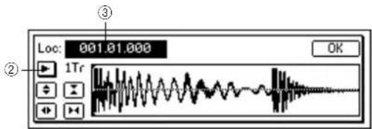
② Use "TrackSelect" to select the track that you want to play.
③ Select "Loc," and turn the [VALUE] dial to search for the location while you listen to the sound.
The track audio will play as you rotate the [VALUE] dial.
Play From function
Press the [SCRUB] key to access the Scrub page, and then press the [PLAY] key. The sound will begin playing from the current location. After two seconds, it will stop and automatically return to the location where you were stopped.
Play To function
Press the [SCRUB] key to access the Scrub page, and then hold down the [STOP] key and press the [PLAY] key. The sound will begin playing from two seconds earlier than the current location, and will stop playing when it reaches the location where you were stopped. By using the Play From and Play To functions you can find a location more accurately.
Slow Play function
Press the [SCRUB] key to access the Scrub page, and press the [FF] key to play at half-speed from the location at which you are currently stopped. When you press the [STOP] key, playback will stop and you will return to the previous location.
note Since the audio will play slowly and at one octave below the actual pitch, you can use this in conjunction with the Pitch Shifter to learn, play along or practice complex phrases that would be difficult to learn at full speed.
3. Editing a song
Songs you have recorded can be copied (duplicated), deleted, or arranged in a different order. You can also protect a song, to keep it from being accidentally deleted.
Song editing operations cannot be undone by the Undo function.
3-1. Song editing operations
Copying a song: "CopySong"
This operation copies the selected song to the song number you specify.
- You can use this to create alternative mixes or arrangements of the same song.
To copy a song
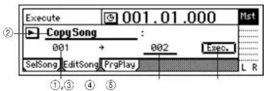
① Select the song that you want to copy. (→p.31)
② In the [SONG] "EditSong" tab page, move the cursor to "EditType," and turn the [VALUE] dial to select "CopySong."
③ Make sure "SourceSong" indicates the song you want to copy.
④ Move the cursor to "DestSong," and turn the [VALUE] dial to select the song number where you want the copy of the song to be located.
⑤ Select the "Exec." button and press the [ENTER] key. When "AreYouSure?" appears, press the [YES/OK] key to execute the operation.
When the operation is completed, the display will indicate "Completed." Press the [YES/OK] key to close the dialog box.
Moving a song: "MoveSong"
This operation moves the selected song to a different song number.
• Y ou can use this to change the order of the songs.
To move a song
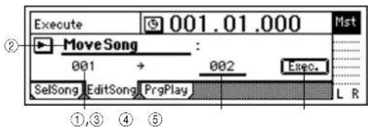
① Select the song that you want to move. (→p.31)
② In the [SONG] "EditSong" tab page, move the cursor to "EditType" and turn the [VALUE] dial to select "MoveSong."
③ Make sure that "SourceSong" indicates the song you want to move.
④ Move the cursor to "DestSong," and turn the [VALUE] dial to specify the destination song number.
⑤ Select the "Exec." button and press the [ENTER] key. When "AreYouSure?" appears, press the [YES/OK] key to execute the operation. When the operation is completed, the display will indicate "Completed." Press the [YES/OK] key to close the dialog box.
Deleting a song: "DeleteSong"
This operation deletes the selected song.
To delete a song
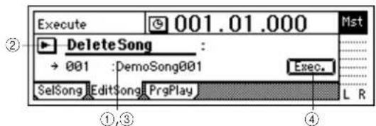
① Select the song that you want to delete. (→p.31)
② In the [SONG] "EditSong" tab page, move the cursor to "EditType" and turn the [VALUE] dial to select "DeleteSong."
③ Verify the song that you want to delete.
Make sure that "DestSong" indicates the song you want to delete.
④ Select the "Exec." button and press the [ENTER] key. When "AreYouSure?" appears, press the [YES/OK] key to execute the operation.
When the operation is completed, the display will indicate "Completed." Press the [YES/OK] key to close the dialog box
Protecting a song: "ProtectSong"
This operation protects the selected song, preventing it from being edited, rewritten or deleted.
If this Protect setting is turned on, it will not be possible to write any parameters of that song; for example, an error will be displayed if you attempt to record, and recording will stop.
- When you have completed a song, you can use this to prevent it from being accidentally rewritten or deleted.
To protect a song
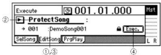
① Select the song that you want to protect. (→p.31)
② In the [SONG] "EditSong" tab page, move the cursor to "EditType" and turn the [VALUE] dial to select "ProtectSong."
③ Make sure that "DestSong" indicates the song you want to protect.
④ Switch the Protect setting on/off.
Select the "Exec." button and press the [ENTER] key. A "☐" symbol will be displayed to indicate the song is protected. The on/off setting will alternate each time you select the "Exec." button and press the [ENTER] key.
Mixer
1. Inputting audio to the mixer
The D1200 has four channels of analog input and one (two-channel) digital input. Audio from devices connected to these input jacks can be assigned to the mixer channels, monitored and recorded. If the CDRW-1 CD-R/RW drive option (sold separately) is installed, you can also assign the audio from an audio CD to the mixer channels.
This section explains how to assign the various inputs to the mixer channels.
1-1. Analog input
Create a new song before you proceed with the following steps.
Connecting a guitar to the [GUITAR IN] jack, assigning it to mixer channel 1, and adjusting the levels
① Set the INPUT 1 [TRIM] knob to the minimum position (+4 dB) and lower the [MASTER] fader. Then connect your guitar to the [GUITAR IN] jack jack on the front edge of the D1200.
② Access the [INPUT/OUTPUT/SOLO] "Ch1-6" tab page, select the "Ch1" icon, and turn the [VALUE] dial to select "INPUT1."
The [GUITAR IN] input jack is now assigned to mixer channel 1.
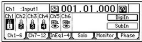
③ Press the track 1 [TRACK STATUS] key to set it to INPUT (LED lit orange).
④ Press the [METER/TRACK VIEW] key. Select the button and press the [ENTER] key to open the dialog box.
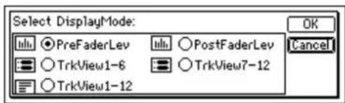
Select the "PreFaderLev" radio button, press the [ENTER] key, and press the [YES/OK] key. When you play your guitar, the track 1 level meter will move accordingly. While you watch the level meter, adjust the INPUT 1 [TRIM] knob. Raise the [TRIM] knob as far as possible without allowing the level meter to reach the CLP level when you play your guitar at its loudest level.
![KORG D1200CD - Connecting a guitar to the [GUITAR IN] jack, assigning it to mixer channel 1, and adjusting the levels - 3](/content/2026/05/820878/images/f2d6fd9b254163569524b56fe8aa1895f9a79ef29254aaea54c9d062a26c42ad.jpg)
bar
| Label | Value | |---|---| | -6 | 12 | | -12 | 24 | | -24 | 12 | | -56 | 12 | | -68 | 12 | | 1 | 2 | | 2 | 3 | | 4 | 5 | | 6 | 6 | | 7 | 8 | | 9 | 9 | | 10 | 10 | | 11 | 11 | | 12 | 12 | CLP CLP CLP CLP CLP CLP CLP CLP CLP CLP CLP CLP CLP CLP CLP CLP CLP CLP CLP CLP CLP CLP CLP CLP CLP CLP CLP CLP CLP CLP CLP CLP CLP CLP L R L R- Set the [MASTER] and [CHANNEL 1] faders to unity gain (0 dB).
- Access the [INPUT/OUTPUT/SOLO] "Monitor" tab page.
- Select the "MasterLR" button and press the [ENTER] key to turn it "On" (highlighted).
- Slowly raise the [PHONES LEVEL] knob or [MONITOR OUT LEVEL] knob, and verify that you hear sound from the headphones or from the monitor speakers etc. connected to the [MONITOR OUT] jacks.
![KORG D1200CD - Connecting a guitar to the [GUITAR IN] jack, assigning it to mixer channel 1, and adjusting the levels - 4](/content/2026/05/820878/images/7f247a306290a2aa7f3636eeaf8545618270b5c5fb888fd402c41c515de7c351.jpg)
flowchart
graph TD
    A["Cue"] --> B["Level"]
    B --> C["Rhythm"]
    C --> D["MonitorBus"]
    D --> E["AutoIn"]
    E --> F["Phase"]
    G["Ch1-6"] --> H["Ch7-12"]
    H --> I["InEq1-4"]
    I --> J["Solo"]
    J --> K["Monitor"]
    K --> L["Phase"]
Using the tuner
The D1200 has a built-in tuner. Here's how to tune an instrument connected to the [INPUT 1] or [GUITAR IN] jack.
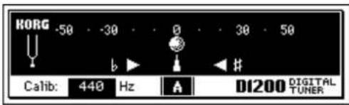
① Press the [TUNER] key to access the tuner screen.
② Use "Calib" to specify the reference frequency. Normally you will set this to "440 Hz."
③ Play a note your instrument.
- The note name that is closest to the input pitch will be displayed.
- If the pitch is correct, "will appear at the 0 position in the center of the meter, and the "(flat) and (sharp) symbols will both light.
If the pitch is flat, only "will light. If the pitch is sharp, only "will light.
note The amount of pitch deviation is displayed in units of cents. (100 cents = semitone; 1200 cents = 1 octave)
note This page cannot be selected during recording or play-back. Nor can you perform recording here.
note In order to detect the pitch accurately, the effects will automatically be turned off while this page is displayed.
1-2. Digital input
The D1200 lets you input and record a digital signal using the S/P DIF input.
The S/P DIF input contains a sampling rate converter. If the connected input source has a sampling rate of 48 kHz or 32 kHz, it will automatically be converted to 44.1 kHz.
Inputting audio from a DAT connected to the [S/P DIF IN] jack into mixer channels 1 and 2
① Lower the [MASTER] fader of the D1200, and use an optical digital cable to connect the digital output of your DAT to the [S/P DIF IN] jack.
② Access the [INPUT/OUTPUT/SOLO] "Ch1-6" tab page.
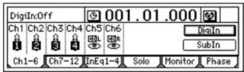
Select the "DigiIn" button, and press the [ENTER] key. A message of "Obey Copyright Rules" will appear.
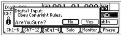
Carefully read the owner's manual section "COPYRIGHT WARNING" (→p.1), and if you accept the conditions, press the [YES/OK] key in response to "AreYouSure?" The digital input is now enabled.
③ Select the "Ch1" icon and turn the [VALUE] dial to select "S/P DIF L." Then select the "Ch2" icon and turn the [VALUE] dial to select "S/P DIF R." The digital input from the [S/P DIF IN] jack is assigned to mixer channels 1 and 2.
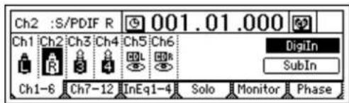
④ Play back your DAT, and press the track 1 and 2 [TRACK STATUS] keys to set them to INPUT (LED lit orange).
⑤ Next, check the digital input audio levels. For instructions, refer to steps ③, ④, and ⑤ of "Connecting a guitar to the [GUITAR IN] jack, and assigning it to mixer channel 1."
Insert effects cannot be used when using digital input.
2. Adjusting the mixer
In the mixer section you can create the overall "mix" by adjusting the volume, tone, and panning of the inputs that are assigned to each mixer channel, or to the recorded sounds that are being played back.
note For details on adjusting the effects, refer to "Effects" ( p.42).
2-1. Adjusting the volume
Use the [CHANNEL] faders to adjust the input, recording, or playback volume of each channel. Raise or lower the fader to set the appropriate volume.
Note The [CHANNEL] faders adjust the gain in a range from silence ( - ) all the way up to +12 dB.
Note Normally you should set the faders to unity gain (0 dB - the input signal is output at the same volume), and lower the faders of channels that are too loud rather than raising the faders of channels that are too quiet. This will make it less likely that the sound will clip (distort).
- If pairing is on, use the odd-numbered channel fader to adjust the volume. (→p.37)
- Fader settings can be registered in a scene. (→p.39)
To adjust the volume level of each input channel
Use the [CHANNEL] faders to adjust the volume level of each mixer channel assigned in the [INPUT/OUTPUT/SOLO] "Ch1-6" or "Ch7-12" tab page.
Since the output level will differ depending on the equipment that is connected, use the [TRIM] knobs to make adjustments as described in steps ③ and ④ of "Connecting a guitar to the [GUITAR IN] jack, assigning it to mixer channel 1, and adjusting the levels" (→p.35).
To adjust the overall volume level
Use the [MASTER] fader to adjust the volume of the master LR bus that is output from the headphones and the [MASTER OUT] jacks.
2-2. Adjusting the pan
Use the [PAN] or [BALANCE] knobs to adjust the location of each channel in the stero field.
- When pairing is on, the knob of the odd-numbered channel can be used as a [BALANCE] knob to adjust the position of the sound. (-p.38)
- Pan settings can be registered in a scene. (→p.39)
Channel 1-6 [PAN] knobs
Turn the knob toward L to move the sound left, or toward R to move the sound right.
Channel 7-12 [BALANCE] knobs
Turn the knob toward L to increase the volume of the odd-numbered channel. Turn the knob toward R to increase the volume of the even-numbered channel.
note Normally you will pan the vocals and bass to the center, and spread the other instruments out across the stereo field. As an example, guitar might be to panned to the left, with the piano balancing it on the right.
When recording in stereo
If you want to input a stereo source to tracks 7/8–11/12 and record it in stereo, set the channel 7/8–11/12 [BALANCE] knobs to the center. Similarly, if you want to turn pairing (=PAN) on for a pair of channels 1/2–5/6
and record in stereo, set the [PAN] knob of the odd-numbered paired channel to the center.
2-3. Using EQ to adjust the tone
A three-band equalizer (EQ) is available to adjust the tone of each input channel and each playback channel.
- T o adjust the input sound (analog), make EQ adjustments in the [INPUT/OUTPUT/SOLO] "InEq1-4" tab page. These settings will affect the tone for recording.
- To adjust the track playback sound, make EQ adjustments in the [EQ] "Eq1–4," "Eq5–8," and "Eq9–12" tab pages.
note EQ is used to cut obtrusive frequency regions such as hiss, or to cut or boost the low or high ranges. Normally, you should adjust EQ so that the tone is clear and well-defined. Excessive EQ settings such as boosting the EQ gain of each channel to the maximum value will make the overall mix uneven, and cause listening fatigue. Use EQ in the "cut" direction as well. It is best to use the minimum amount of EQ that will achieve the desired result.
- If pairing is on, use the odd-numbered "Eq" to make adjustments. (→p.38)
- EQ settings can be registered in a scene. ( p.39)
Applying EQ to an analog input/Applying EQ as you record
You can apply EQ to an analog input (not to the digital input), and record the sound using these EQ settings.
① Access the page that contains the channel where you want the EQ to be applied, by selecting the [INPUT/OUTPUT/SOLO] "InEq1-4" tab page.
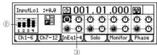
② Input an audio signal, and adjust the level appropriately. Refer to "Connecting a guitar to the [GUITAR IN] jack, assigning it to mixer channel 1, and adjusting the levels" ( p.35). Verify that the level meter at the left edge of the display moves, and that you can hear the sound.
③ Select the "InputEQ" gain settings and mid EQ frequency, and turn the [VALUE] dial to adjust them.
High EQ, Low EQ
- Select "High EQ Gain (H)" or "Low EQ Gain (L)" for the channel you want to adjust, and turn the [VALUE] dial to adjust the gain. The value is shown in the upper left of the screen.
Mid EQ
- Select "Mid EQ Frequency (F)" for the channel you want to adjust, and turn the [VALUE] dial to adjust the frequency. The value is shown in the upper left of the screen.
- Select "Mid EQ Gain (M)" for the channel you want to adjust, and turn the [VALUE] dial to adjust the gain. The value is shown in the upper left of the screen.
④ Record the sound as processed by the EQ. (→p.53)
Applying EQ to the track playback sound
- The EQ that is applied to the track playback sound can be adjusted in the [EQ] "Eq1–4," "Eq5–8," and "Eq9–12" tab pages. Refer to Quick Start Tutorial. (→p.26)
2-4. Pairing
By specifying adjacent odd-numbered and even-numbered channels (1–2, 3–4, 5–6) as a pair, you can adjust the values of both channels simultaneously by editing the value of the odd-numbered channel.
This is convenient when you want to make mixer settings for a stereo-recorded track.
The following settings can be paired.
• [TRACK STATUS] key
• EQ (channel EQ)
• E f fSnd1+2 (effect send)
- AuxSend (external send)
• [ P AN] knob
• [CHANNEL] fader
Note The [TRACK STATUS] keys and [CHANNEL] faders will be paired automatically when you pair two channels. For [EQ], [EffSnd], [AuxSend], and [Pan], you can specify individually whether pairing will be enabled.
① Select the “(SelChPair) button in the [INPUT/OUTPUT/SOLO], [EQ], or [INSERT EFFECT] pages, and press the [ENTER] key to open the “Select Channel Pair” dialog box.
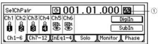
② Here you can select which channels you would like to pair. Select one of the "1 2"–"5 6" button, and press the [ENTER] key so that the button is displayed with a "☐."
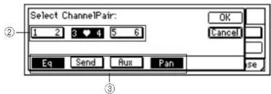
③ Select the functions that will be paired for the channels you selected in "Select Channel Pair." Select the "Eq," "Send," "Aux," and "Pan" function that you want to pair, and press the [ENTER] key to turn pairing "On." Press the [YES/OK] key to apply the setting.
2-5. Monitor settings
In order to monitor the sound of the D1200, you must connect monitor speakers to the [MONITOR OUT L/R] jacks, or connect headphones to the [PHONES] jack for monitoring.
To select which signals will be monitored
① Access the [INPUT/OUTPUT/SOLO] "Monitor" tab page.
- Normally you will select "MasterLR." Select the "MasterLR" button and press the [ENTER] key to turn it "On" (highlighted).
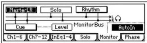
flowchart
graph TD
    A["Testen"] --> B["Solo"]
    B --> C["Rhythm"]
    C --> D["MonitorBus"]
    D --> E["AutoIn"]
    F["Cue"] --> G["Level"]
    G --> H["MonitorBus"]
    H --> I["AutoIn"]
    J["Ch1-6"] --> K["Ch7-12"]
    K --> L["InEq1-4"]
    L --> M["Solo"]
    M --> N["Monitor"]
    N --> O["Phase"]
Note If the "Solo" function is on, it will override any settings here. Turn the "Solo" function off before making a selection.
② For mixer channels whose [TRACK STATUS] is PLAY (LED lit green), you will hear the track playback when the recorder is playing.
For mixer channels whose [TRACK STATUS] is REC (LED lit red), you will hear the sound of the external input.
Note If the "AutoIn" button is "On," and the [TRACK STATUS] of a mixer channel is "REC," you will hear the sound of that track during playback, and the sound of the external input while recording and when stopped. This is useful when doing "punch in/out" recording. If "AutoIn" is "Off," you will always hear the sound of the external input.
③ Use the [MONITOR OUT LEVEL] knob to adjust the volume of the [MONITOR OUT L/R] jacks, and the [PHONES LEVEL] knob to adjust the volume of the [PHONES] jack.
2-6. Adjusting the cue level
The [CHANNEL] faders of the D1200 are used to adjust both the recording level of each track and the volume level of each channel, so the levels being recording will be the same as the monitor volume levels.
For this reason, a Cue Level function is provided so that you can monitor using a completely different mix of volume and pan settings while you perform, regardless of the master LR settings.
To adjust the Cue Level
① In the [INPUT/OUTPUT/SOLO] "Monitor" tab page, turn the "Cue" button "On."
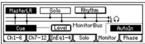
flowchart
graph TD
    A["MasterLR"] --> B["Cue"]
    C["Solo"] --> D["Level"]
    E["Rhythm"] --> F["MonitorBus"]
    G["AutoIn"] --> H["Ch1-6"]
    G --> I["Ch7-12"]
    G --> J["InEq1-4"]
    G --> K["Solo"]
    G --> L["Monitor"]
    G --> M["Phase"]
    B -.-> D
    D -.-> F
    F -.-> G
    H -.-> I
    I -.-> J
    J -.-> K
    K -.-> L
    L -.-> M
Note If the "Solo" function is on, it will override any settings here. Turn the "Solo" function off before making a selection.
② Select the "Level" button and press the [ENTER] key to access the Cue Level setting screen. Select the icons for each channel, and turn the [VALUE] dial to adjust the volume level and pan that is displayed in the upper left.
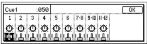
2-7. Solo settings
If a "Solo" button is "On," only that signal will be sent to the monitor bus. Use this when you want to hear just one of several audio sources, or to check the send signal. The solo signal will be output from the [MONITOR OUT L/R] jacks and the [PHONES] jack.
To select a signal for soloing
① Begin by selecting the signal that you want to solo, and turn Solo on. Access the [INPUT/OUTPUT/SOLO] "Solo" tab page.
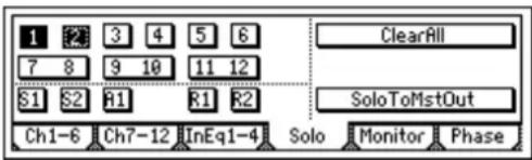
Select the appropriate "Solo" button, and press the [ENTER] key to switch solo "On" (highlighted) for that signal. If solo has been turned "On" for even one signal, the [INPUT/OUTPUT/SOLO] key will blink.
note You may select more than one signal for soloing.
② Adjust the monitor volume. Use the [MONITOR OUT LEVEL] knob or [PHONES LEVEL] knob to adjust the volume level.
To turn solo off
- Access the [INPUT/OUTPUT/SOLO] "Solo" tab page, and turn the "Solo" button(s) "Off."
- If you select the "ClearAll" button and press the [ENTER] key, all solo settings will be turned off.
To output the solo signal from master LR
You can output the solo signal from [MASTER OUT L/R] if desired. Use this when you want to output the solo signal from the monitor system connected to the [MASTER OUT L/R] jacks.
- In the [INPUT/OUTPUT/SOLO] "Solo" tab page, turn the "SoloToMstOut" button "On" (highlighted). However, this will automatically be turned "Off" when you leave the [INPUT/OUTPUT/SOLO] page.
3. Registering and recalling a scene
The current mixer settings can be registered as a "scene." Scenes can be recalled automatically as the song plays. You can also register frequently-used mixer settings for recall as desired, re-register the recalled settings at a different location, or edit some of the settings and overwrite them over the original scene. Scenes can be renamed, and can be sorted by their order of appearance in a song.
Up to 100 scenes can be registered in a song.
The following settings can be registered in a scene.
• EQ
• E f fect settings
• E f fSnd (effect send)
- AuxSend (auxiliary send)
• [ P AN] and [BALANCE] knobs
• [CHANNEL] faders
Note The faders and pan/balance knobs of the top panel do not actually move when a scene is recalled. However the [SCENE] "MixView" tab page lets you see the value for these settings as the scenes change.
3-1. Registering a scene
① Move to the location in the song where you want to register a scene.
Use the counter or [FF]/[REW] to move ( p.32).
② Make the desired mixer settings.
Adjust the [CHANNEL] faders, [PAN] knobs, EQ, and effects etc. to create a new scene.
③ To register the scene:
- Press the [STORE] key to capture the current time.
- Press the [SCENE] key. The display will indicate the scene number as "SCENE***", and the parameters will be registered.
note When a scene is registered, it is assigned the lowest unused number. You can perform step ③ even while a song is being played or recorded.
3-2. Switching scenes during playback
Here's how scenes can be automatically switched as the playback time progresses.
note Register scenes at the locations where you want the mixer settings to change. (→ "3-1. Registering a scene")
Automatically switching scenes while a song plays
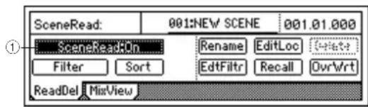
① Access the [SCENE] "ReadDel" tab page, and turn "SceneRead" on.
- When this is on, the [SCENE] key will light.
② Play back the song.
Move to the location from which you want to play back, and press the [PLAY] key to play the song.
When you reach the location at which a scene was registered, the scene will change automatically.
3-3. Recalling a scene
At any time, you can manually recall the mixer settings registered in a scene, regardless of the time at which the scene was registered.
To recall the mixer settings registered in a scene
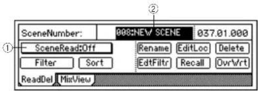
① Access the [SCENE] "ReadDel" tab page, and turn "SceneRead" off.
- When this is off, the [SCENE] key will be dark.
note If "SceneRead" is "On," it will not be possible to recall a scene that was registered at another time location.
② Recall the scene.
In the [SCENE] "ReadDel" or "MixView" tab page, move the cursor to "SceneNumber" and turn the [VALUE] dial to select a scene. The selected scene will be recalled.
3-4. Changing the time at which a scene is registered
You can change the counter location of a registered scene, so that it is selected at a different place in the song.
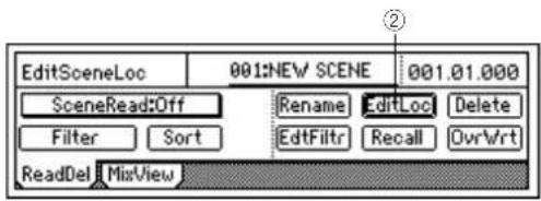
① Recall the scene.
As described in "3-3. Recalling a scene," select the scene whose time you want to change.
② Change the time of the scene.
- Select the "EditLoc" button and press the [ENTER] key.
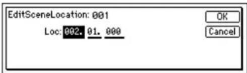
- Specify the desired counter location in the dialog box, and press the [YES/OK] key.
3-5. Re-registering a scene at another time location
You can re-register the same scene at different locations.
① Recall the scene that contains the mixer settings you want to re-register.
As described in "3-3. Recalling a scene," recall the desired scene.
② Move to the location where you want to re-register the scene. (→p.32)
③ Press the [STORE] key and then the [SCENE] key.
3-6. Editing and overwriting a scene
Here's how to edit the settings of a scene and overwrite the changes onto the existing scene.
① As described in "3-3. Recalling a scene," recall the scene that you want to edit.
② Adjust the [CHANNEL] faders, [PAN] knobs, EQ, and effects etc. to the desired settings.
③ In the [SCENE] "ReadDel" tab page, make sure that the scene number you want to overwrite is selected.
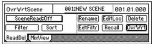
- Select the "OvrWrt" button and press the [ENTER] key.
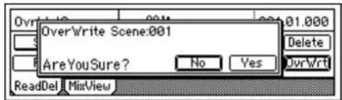
Press the [YES/OK] key to overwrite the settings for that scene number.
3-7. Deleting a scene
Here's how to delete an unwanted scene.
This operation cannot be undone.
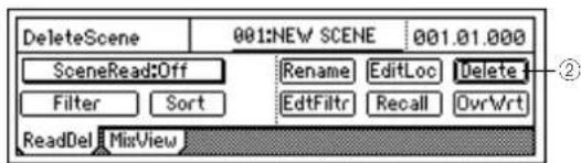
① As described in "3-3. Recalling a scene," recall the scene that you want to delete. If you want to delete all scenes, select any of the scenes.
② In the [SCENE] "ReadDel" tab page, select the "Delete" button and press the [ENTER] key.
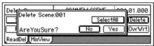
Verify the "Delete Scene" number shown in the upper left, and if this is the scene you want to delete, press the
[YES/OK] key to delete it. The scene will not be deleted if you press the [NO/CANCEL] key. If you want to delete all scenes, select the "SelectAll" button and press the [ENTER] key to turn it "On." Then press the [YES/OK] key to delete all scenes.
3-8. Applying filtering to all scenes
Applying filters will allow you to prevent specific parameters on each channel from being affected by scene changes. This can be a very handy feature.
① In the [SCENE] "ReadDel" tab page, select the "Filter" button and press the [ENTER] key to make the display show "Select SceneFilter."
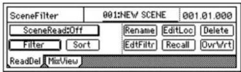
② Select the parameter(s) that you want to disable. There are two pages of settings, so use the "Next" button to view the next page.
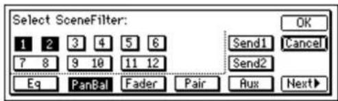
The first page contains parameters for each channel. For example if you want the Scene Filter to prevent scene changes from affecting the pan settings of channels 1 and 2, you would turn "1," "2," and the "PanBal" button "On."
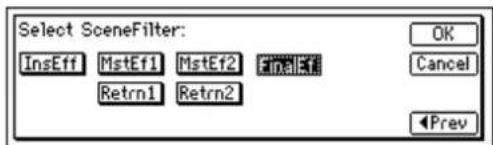
The second page contains parameters that apply to the overall mix. As in the first page, turn "On" filtering for parameters that you do not want to be affected by scene changes. Press the [YES/OK] key to apply the settings.
3-9. Using MIDI to control scenes
MIDI output
When the scene changes, a scene change message (program change) will be transmitted in the following cases.
- When you use "SceneNumber" in the [SCENE] "ReadDel" tab page to switch scenes.
- When you press the [STORE] key and [SCENE] key to register a scene.
- When "SceneRead" is "On" and the scene changes during playback or recording.
MIDI input
If "SceneRead" is "Off," scene change messages (program changes) that are received will cause the D1200 to select the scene of the corresponding number. If "SceneRead" is "On," these messages will not be received, regardless of whether the D1200 is playing, recording, or stopped.
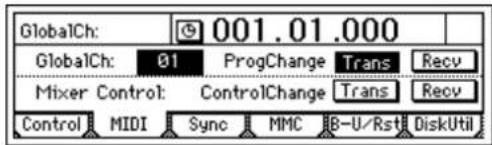
① Connect an external MIDI device. (→p.79)
② In the [SYSTEM/USB] "MIDI" tab page, set "GlobalCh" to match the channel of the external MIDI device that will be transmitted the messages.
If you want the D1200 to transmit MIDI messages, set the [SYSTEM/USB] "MIDI" tab page "ProgChange" parameter "Trans" to "On."
If you want the D1200 to receive MIDI messages, set the [SYSTEM/USB] "MIDI" tab page "ProgChange" parameter "Recv" to "On."
③ In the [SCENE] "ReadDel" tab page, set "SceneRead" to "Off"
④ Transmit a program change message from the external MIDI device to recall a scene on the D1200.
When the D1200 receives program change #0 it will recall scene "001." Program changes #0–99 correspond to scenes "001"–"100."
Effects
Overview of the effects
On the D1200 you can use up to eight insert effects that can be applied to individual analog inputs or mixer channels, two master effects that can be applied in varying amounts to the send from each channel, and a final effect that can be applied to the master LR as the last stage. Each of these effects are independent, meaning that you can simultaneously use up to eleven effect programs.
• E f fect algorithms: total of 98
• E f fect programs:
| Preset (192) User (192) | ||
| Insert effects I000, I0 | 01-I128 U001-U128 | |
| Master effects M000, | M001-M032 u001-u032 | |
| Final effects F000, F | 001-F032 u033-u064 |
Preset effects contain effect programs created by professional musicians and studio engineers.
User effects can store effect programs that you created by editing a preset effect.
note It is not possible to rewrite a preset effect program.
1. Using insert effects
These effects are “inserted” directly into the signal path of either an analog input signal or a playback track. Effects can also be applied to the internal PCM rhythms if they are being routed to a mixer channel.
There are four types of insert effects. The effect programs that are available will depend on the type of effect you select. ( p.127, 154)
○ 1 in 2 out x 2, 1 in 1 out x 2 (input only)
These are mono-in/stereo-out or mono-out chain effects. You can use two of these chain effects simultaneously.
These are ideal for adding spaciousness to a lead guitar or vocal.
- When simultaneously recording guitar and bass, you can apply a Guitar Multi effect to the guitar input and a Bass Multi effect to the bass input as you record.
- When simultaneously recording two vocals, you can apply separate Vocal Multi effects to each vocal input as you record.
- When simultaneously recording vocal and guitar, you can apply a Vocal Multi to the vocal and a Guitar Multi to the guitar as you record.
○ 2 in 2 out x 2
These are stereo-in/stereo-out effects. You can use two of these effects simultaneously.
These are ideal for a stereo input sources such as a keyboard.
- When simultaneously recording a keyboard and rhythm machine, you can apply St.Chorus to the keyboard and St.Comp to the rhythm machine.
- You can apply St.Comp or St.Limiter to adjust the dynamics of drums that are recorded in stereo, or apply Reverb to create spaciousness (when playing back the track).
○ 1 in 1 out x 4
These are mono-in/mono-out chain effects. You can use four of these chain effects simultaneously.
These are ideal for sources whose stereo position is fixed, such as rhythm guitar.
- When recording four vocals simultaneously, you can apply Exciter-Comp to voices that lack impact, and Limiter-P4EQ to powerful voices.
○ 1 in 1 out x 8 (during track playback only)
Only during track playback, you can use eight mono-in/mono-out effects.
These are ideal for sources whose stereo position is fixed, such as drums.
- You can use Comp, Limiter, Gate, or Expander to adjust the dynamics of each recorded track, or apply Chorus, Phaser, or Delay.
In the case of a 24-bit song, only six of these effects can be used.
1-1. Applying insert effects while you record (analog or rhythm only)
While recording, you can apply effects to the input from instruments connected to the [INPUT 1/GUITAR IN]-[INPUT 4] analog input jacks or to the internal rhythm sounds if they are input to a mixer channel. If the optional CDRW-1 is installed, you can also apply effects to the sound from an audio CD.
Applying an effect to a guitar connected to the [GUITAR IN] jack, and recording it to track 1
① Plug in the guitar, and select the track where you want to record.
Refer to "Connecting a guitar to the [GUITAR IN] jack, assigning it to mixer channel 1, and adjusting the levels" (→p.35).
② Access the [INSERT EFFECT] "InsAss" tab page.

③ Select the "Assign:" button, and press the [ENTER] key. Select "Input (In)," press the [ENTER] key, and press the [YES/OK] key.
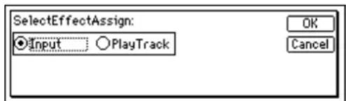
④ Select one of the "SelectEffType:" buttons and press the [ENTER] key to select the effect type.
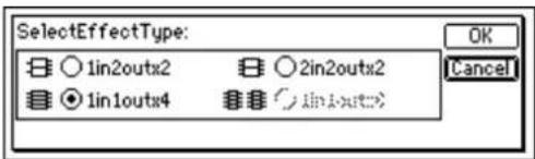
⑤ Insert the effect between INPUT 1 (GUITAR IN) and channel 1.
- Select the "InsertTo:" button and press the [ENTER] key.
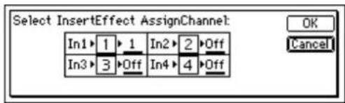
- For "In1," set "SelectCh" to "1," and then press the [YES/OK] key.
⑥ Select the effect program.
- Access the [INSERT EFFECT] "InsEff1" tab page.
- Select "EffectNumber," and turn the [VALUE] dial to select an effect program.
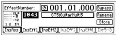
1-2. Applying insert effects during playback
You can apply insert effects to the playback of previously-recorded tracks.
For the procedure of applying insert effects to the track play-back, refer to the Quick Start Tutorial. (→p.25)
2. Using the master effects
To use the master effects, set the Send Level of each track to send its signal to the master effect. The master effects are used to add depth to the overall mix, or improve the balance. The D1200 provides two master effects (MstEff1 and MstEff2), and they can be used simultaneously. The depth of each effect is adjusted by the send level that is sent from each track to the effect.
Use AUX send when you want to apply an external effect. For details on using master effects, refer to the Quick Start Tutorial. (→p.27)
3. Using the final effect
The D1200 provides one stereo-in/out final effect. It is applied to the master LR signal. The final effect is used mainly for dynamic processing (such as compression) to regulate the overall level.
You can achieve high-quality results by applying a mastering effect such as a multi-band limiter to add a finishing touch to the sound during mastering.
① Access the [FINAL EFFECT] "FinalEff" tab page.
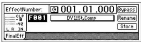
② Select an effect program.
Select "EffectNumber," and turn the [VALUE] dial to select an effect program. Play back the song, and listen to the master LR output to hear the result of the effect.
4. Editing an effect
You are free to edit any effect program used as an insert effect, master effect, or final effect.
If you switch the "EffectNumber" or turn off the power without saving, your edited effect settings will be lost. If you want to keep your edited effect settings, you must save them. (→ p.44)
To edit an effect
① Access the page for the effect you want to edit.
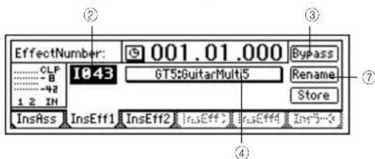
② Select "EffectNumber," and turn the [VALUE] dial to select the effect program that you want to edit.
③ Listen to the sound of the effect program. If you select the "Bypass" button and press the [ENTER] key, bypass will be turned on (you will hear the sound without the effect). If you then select the "Cancel" button and press the [ENTER] key, bypass will be turned off (the effect will be applied once again). This lets you compare the sound with and without effects.
④ Select the "EditEffect" button and press the [ENTER] key. The dialog box will appear, showing the structure of that effect.
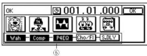
⑤ Turn off each individual effect as necessary. Select the “(Effect On/Off)” button located below each “(EffectIcon)” button, and press the [ENTER] key to switch it on (highlighted) or off.
⑥ Edit the settings of each effect.
- Select the “(EffectIcon)” button of the effect you want to edit, and press the [ENTER] key.
- Select a parameter, and use the [VALUE] dial to edit the value. For details on each parameter, refer to the "Effect Parameter List" (→p.127).
- You can hear the results of the effect by switching the "Effect On/Off" field in the upper part of the dialog box. This on/off setting is the same as the "(Effect On/Off)" button in step ⑤. Changing one will also change the other.
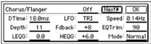
- You are done editing, press the [YES/OK] key. If you want to adjust another effect, select its “(EffectIcon)” button, press the [ENTER] key, and edit the parameters.
- In the "EffectAlgorithm" dialog box, press the [YES/OK] key.
⑦ You can assign a name to your edited effect program.
- Select the "Rename" button and press the [ENTER] key to open the "RenameEffect" dialog box. (→p.31: "1-2. Editing the name of a song")
- When you are done naming the effect, press the [YES/OK] key.
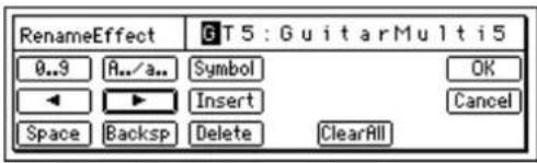
To save the effect program
- If the song is playing, press the [STOP] key to stop playback.
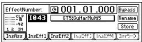
- Select the "Store" button and press the [ENTER] key to open the "StoreEffect" dialog box.
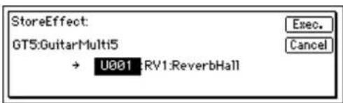
- Specify the number in which you want to save the effect program, select the "Exec." button, and press the [ENTER] key to save the effect program.
note When you save the effect program, the data will be overwritten to that number and any existing settings will be lost.
5. Controlling an effect from an external device
You can use an expression pedal or external MIDI controller to control certain insert effect parameters in realtime. For details on the effect parameters that can be controlled, refer to "Effect Parameter List" (→ p.127).
Using a pedal to control an insert effect
① Connect an expression pedal (such as the optional EXB-2 foot controller) or an external MIDI controller ( p.14).
② Access the [SYSTEM/USB] "Control" tab page.
- In "Device (CtrlChgDevice)," select "Pedal" if you want to use an expression pedal for control.
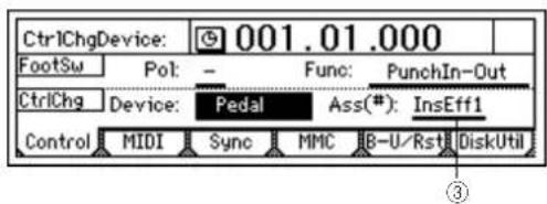
If you want to use MIDI to control the effect, select the MIDI message. In order to use MIDI messages for control, you must set the [SYSTEM/USB] "MIDI" tab page "GlobalCh (Global Channel)" setting to match the MIDI channel of the external MIDI device that will transmit the messages.
③ Chose which insert effect will be controlled. Use "Ass(#) (CtrlChgAssign)" to select "InsEff1" - "InsEff4" as the insert effect that will be controlled.
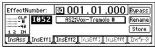
④ Assign an effect program.
- Go to the [INSERT EFFECT] "InsEff1"-"InsEff4" tab page, and select the insert effect that you selected in step ③.
- Select "Effect Number," and turn the [VALUE] dial to select the effect program.
note If the selected effect contains a control function and can be controlled, a “#” symbol will be displayed after the name of that effect program.
⑤ Specify the parameter and range that will be controlled.
- Select the "(EffectProgramName)" button and press the [ENTER] key.
The "Effect Algorithm" dialog box will appear, showing the structure of that effect program.
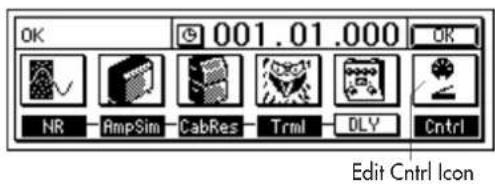
- Select the "EditCntrl Icon" button, and press the [ENTER] key to open the "ControlDevice" dialog box.
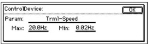
- Select "Param," and turn the [VALUE] dial to select the parameter that you want to control.
- T urn the [VALUE] dial to set "Max" to the maximum value and "Min" to the minimum value.
- When you have finished making settings, press the [YES/OK] key.
- In the "Effect Algorithm" dialog box, press the [YES/OK] key.
note If you want to save these settings, save them as described on p.44.
⑥ Now you can operate the expression pedal or external MIDI controller to control the effect.
6. Using an external effect
You can take the Send signal from the [AUX OUT] jack and run it through an external effect processor. The output of the external effect can then be connected to the [INPUT 1]-[INPUT 4] jacks, and returned to the mixer channels or to the master LR bus.
Sending the playback sound to an external effect, and using [INPUT 3] and [INPUT 4] jacks to return it to the master LR bus
① Connect the D1200's [AUX OUT] jack to the INPUT jack of the external effect, and connect the OUTPUT jacks of the external effect to the D1200's [INPUT 3] jack and [INPUT 4] jack.
② Set the send levels for each channel.
- Access the [MASTER EFFECT/AUX SEND] "Aux-Send" tab page.
- Select "Aux" for the channel(s) that you want to send to the external effect, and use the [VALUE] dial to adjust the send level.
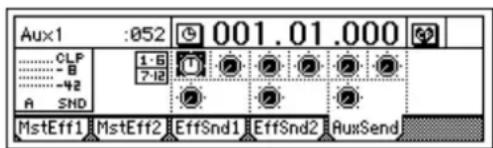
③ Return the audio signal from the external effect unit.
- Access the [INPUT/OUTPUT/SOLO] "Ch1–6" or "Ch7–12" tab page.
- Select the "SubIn" button, and press the [ENTER] key to open the dialog box. Use the "In3–4" "Fader" to adjust the return level, and "Balance" to adjust the return balance. (→p.67, 98)
Modeling mode
The D1200 provides a Modeling mode that makes it easy for you to record using Korg's ToneWorks REMS effects. Dedicated knobs allow you to control the modeling effects as easily as if you were using hardware devices. Refer to "What is REMS?" (→p.6)
In Modeling mode, tracks 1 and 2 are automatically selected and their [TRACK STATUS] is set to REC (lit red). You can begin recording immediately, simply by pressing the [REC] key and then the [PLAY] key.
When you overdub, be sure to record to different tracks so you don't erase anything you had already recorded. Set the [TRACK STATUS] keys of the overdub tracks to REC (red).
note If you want to record in monaural, set only one track to a [TRACK STATUS] of REC (red).
Note The D1200 remembers the last state of Modeling mode even when the power is turned off, and will be available when you turn the power on again.
note A modeling effect you edit cannot be saved as an effect program as it is. Edited Modeling effects must be saved as an insert effect user program. (→p.46)
1. Applying a modeling effect to your guitar
The D1200 provides various modeling effects for use with a guitar, including simulations of distortion-type effect devices, amp heads, and speaker cabinets.
① Press the [MODELING] key, move the cursor to "Guitar" in the left of the screen, and press the [ENTER] key or the [YES/OK] key to enter the guitar modeling effect screen.
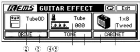
② Select a distortion-type effect.
Of the three knobs located below the display, turn the left knob "DRIVE" to select one of the ten distortion-type modeling effects.
③ Select a pre-amp tone.
Turn the center knob (TONE) to adjust the tone of the vacuum tube premp model. Vacuum tubes add a unique non linear distortion that modifies the overtone structure of the sound.
④ Select the cabinet.
Turn the right knob (CABINET) to choose one of eleven cabinet types.
⑤ Edit the effect parameters.
Move the cursor to "DRIVE," "TONE," or "CABINET" in the display, and press the [ENTER] key to access a screen where you can edit the parameters of the corresponding effect.
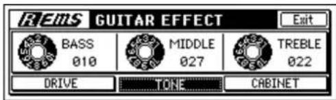
For example if you select "TONE," three parameters will appear; "BASS," "MIDDLE," and "TREBLE."
You can adjust these parameters by turning the three knobs located below the display. If you want to make more precise adjustments, turn the [VALUE] dial to adjust the value.
note To return to the previous screen, move the cursor to the "Exit" button in the upper right of the display and press the [ENTER] key, or press the [CANCEL] key.
If the guitar input level is not appropriate, you may not obtain the distortion or noise reduction effect you expect. Watch the input peak LED while you use the input trim to adjust the level so that it is neither too low or too high (clipping).
2. Applying a modeling effect to your bass
The D1200 provides various modeling effects for use with a bass, including dynamics-type effects as well as modulation and ambience-type effects such as chorus and delay.
note These effects can also be applied to clean (undistorted) guitar sounds.
① Press the [MODELING] key, move the cursor to [Bass] in the middle of the screen, and press the [ENTER] key or the [YES/OK] key to enter the bass modeling effect screen.
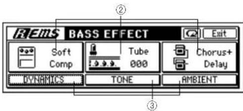
② Use the knobs located below the display to select the desired type for the dynamics, vacuum tube, and ambient effects.
③ Edit the effect parameters. Move the cursor to "DYNAMICS," "TONE," or "AMBIENT" in the lower part of the display, and press the [ENTER] key to access the effect parameter screen for the corresponding effect. For example when you access the DYNAMICS screen, the three parameters "ATTACK," "RELEASE", and "LEVEL" will appear. You can adjust the values of these three parameters by turning the three knobs located below the display. If you want to make precise adjustments to a parameter, you can also use the [VALUE] dial to edit the value.
note If the sound is distorted, you can either lower the input trim or lower the "DYNAMICS" level.
note If the input level for the dynamics-type effect is not appropriate, you may not obtain the result you want. Use
the trim control to adjust the level appropriately for the input.
3. Applying a modeling effect to a mic
The D1200 provides various modeling effects for use with a mic, such as simulations of different types of studio, mic, and dynamics-type effects. These effects are ideal for processing signals from a dynamic mic or line input.
① Press the [MODELING] key, move the cursor to [Mic] at the right of the screen, and press the [ENTER] key or the [YES/OK] key to enter the mic modeling effect screen.
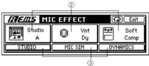
② Use the knobs located below the display to select the desired type for studio, mic, and dynamics.
③ Edit the effect parameters. Move the cursor to "STUDIO," "MIC SIM," or "DYNAMICS" in the display, and press the [ENTER] key to access a screen where you can edit the parameters of the corresponding effect. For example if you enter the DYNAMICS screen, three parameters will appear; "ATTACK," "RELEASE," and "LEVEL." You can adjust these parameters by turning the three knobs located below the display. If you want to make more precise adjustments, turn the [VALUE] dial to adjust the value.
Note If the input level is too low or too high, dynamics-type effects may not produce the result you expect. According to your input source, adjust the trim to obtain an appropriate level.
Note If you are using line input, set the MIC SIM "IN MIC" parameter to "Line." If you are using a dynamic mic, set the "IN MIC" parameter to the type of mic you are using.
4. Saving your modeling effect settings
The modeling effects you edit in Modeling mode are preserved even when the power is turned off. When you turn on the power again, the state of the three effects (for guitar, bass, and mic) will be preserved.
A modeling effect that you edit in Modeling mode can also be edited in greater detail as an insert effect. You will then be able to save the edited insert effect as a user program, and recall it when desired.
You cannot use Modeling mode to edit an effect program that has been saved as an insert effect.
If you want to edit the effect in greater detail and save it
① Edit the effect in Modeling mode ( p.45).
② Access the [INSERT] "InsEff1" tab page.
The [MODELING] key will go dark.
The display will show the insert effect program that you had been editing as a modeling effect.
③ Edit the settings as an insert effect, and save.
Refer to "To edit an effect" ( p.43) and "To save the effect program" ( p.44).
note For details on using an effect program that you saved, refer to "1. Using insert effects" (→p.42).
To exit Modeling mode
To exit Modeling mode, press the [NO/CANCEL] key several times to make the [MODELING] key go dark.
To restore the factory settings
Press the "Button, and the selected modeling effect will return to the factory settings.
5. Operation in Modeling mode
Limitations in Modeling mode
- Only the [INPUT 1] or [GUITAR IN] jacks can be used.
- The [INPUT/OUTPUT/SOLO] "Ch1–6" and "Ch7–12" tab pages will be displayed as follows, and you cannot make Input settings in Modeling mode.
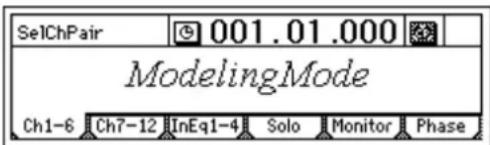
- A maximum of two tracks can be recorded simultaneously.
- If you play back a scene or switch scenes while in Modeling mode, the insert effect settings registered in that scene will not be reflected.
- You cannot set [TRACK STATUS] to INPUT (orange).
5-1. Internal operation in Modeling mode
In Modeling mode, various functions will be set automatically in the following cases.
When you enter Modeling mode
• The [MODELING] key will light.
- All current assignments in the [INPUT/OUTPUT/SOLO] "Ch1-6" and "Ch7-12" tab pages will be memorized, the "DigiIn" button will be turned off, and all input channel settings will be set to "1." "SubIn" will be muted.
- The [BOUNCE] "RecMode" tab page "RecMode" will be set to "Input."
- [TRACK STATUS] for track 1 and track 2 will be set to REC, and the remaining tracks will be set to PLAY.
- In the [INSERT EFFECT] "InsAss" tab page, the insert effect assignment will be set to "Input(In)," and the effect type will be set to "1in2outx2." "InsertTo" will be set to In1 → 1 → upper line (1) lower line (2).
- The insert effect 1 program will be changed.
- The last-used modeling effect settings will be restored.
When you exit Modeling mode
• The [MODELING] key will go dark.
- With the exception of tracks whose [TRACK STATUS] is set to REC, the audio input settings to the mixer will return to the state prior to when you entered Modeling mode.
When you change the track status
If you change the [TRACK STATUS] while in Modeling mode, the "InsertTo" setting of the insert effect will change as follows.
- If you make settings for monaural recording by setting only one [TRACK STATUS] to REC, the "InsertTo" setting will change to "In1 → 1 → upper line (the track set to [REC]) lower (off)".
- If you make settings for stereo recording by setting two [TRACK STATUS] key to REC, the "InsertTo" setting will change to "In1 → 1 → upper line (the track set to [REC]) lower line (the track set to REC +1)".
- If you have not set [TRACK STATUS] to REC, the "InsertTo" setting will not change.
Rhythm
The D1200 contains numerous rhythm patterns in a variety of time signatures ( p.156: "Rhythm Pattern List").
When you have a sudden idea for a song, you can record a performance immediately by using these rhythm patterns as a guide track.
You can also join different rhythm patterns to create drum patterns for an entire song.
1. Selecting and playing a rhythm
Access the [RHYTHM] "SetUp" tab page.
Use this page to make the settings described below.
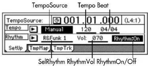
Tuming the rhythm on/off
Select the "Rhythm On/Off" button and press the [ENTER] key to turn it "Rhythm:On" (highlighted).
The [RHYTHM] key will light, and the currently selected rhythm will sound.
The rhythm will sound during playback and recording. If you want to record the rhythm, refer to "3. Recording the rhythm."
Adjusting the rhythm volume
Select "RhythmVol" and turn the [VALUE] dial to adjust the volume.
Setting the tempo and time signature
① Select "TempoSource" and choose the tempo source. For this example, we will select "Manual," so that the tempo, time signature, and rhythm pattern will not change.
note You can also select the "button and press the [ENTER] key to choose from a list.
If you want to change the tempo, time signature, and rhythm pattern during the song, you must create a tempo map. ( p.49)
② Select "Tempo," and turn the [VALUE] dial to adjust the tempo.
③ Select "Beat," and turn the [VALUE] dial to specify the time signature.
Selecting a rhythm pattern
Select "SelRhythm," and turn the [VALUE] dial to choose a rhythm pattern.
note You can also select the "button and press the [ENTER] key to choose from a list.
2. Listening to the rhythm while you record a performance
Here's how you can listen to the rhythm pattern as a guide while you record your playing.
① Use the procedures described in "1. Selecting and playing a rhythm" to turn the "Rhythm" "On" and make any other necessary settings.
② Connect your instrument, and get ready to record. Refer to "1. Assigning inputs to the mixer" (→p.22). Press the [REC] key to enter record-ready mode, and the rhythm will start playing. Press the [PLAY] key and recording will begin. Play along with the rhythm pattern you selected.
note With these settings, the rhythm cannot be recorded.
3. Recording the rhythm
Here's how you can take a rhythm pattern and record it as part of your song.
Recording a rhythm pattern on tracks 1 and 2
① Make settings as described in "1. Selecting and playing a rhythm."
- T urn "Rhythm" "Off."
Note If this is "On," the sound will be output in duplicate; both to the tracks and to the master LR bus.
- The volume will be adjusted by the mixer input channels. The "RhythmVol" is the send level only to the master LR bus, so you do not need to set it.
• Make any other settings as necessary.
② Specify the input channels.
- Select the [INPUT/OUTPUT/SOLO] "Ch1-6" tab page.
- Select the "Ch1" icon, and turn the [VALUE] dial to select "RhythmL." In the same way, set "Ch2" to "RhythmR."
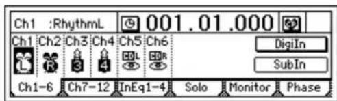
③ Record the rhythm.
Refer to "1-1. Basic recording" (→p.53).
4. Setting the tempo of a song
By selecting one of the three options for "TempoSource" you can either play an entire song at the same tempo, change the tempo during the song, or synchronize it with an external MIDI device.
- Manual tempo: The entire song is played at one tempo.
- Tempo map: Tempo changes can be programmed throughout the song.
- Tempo track: MIDI Clock or tap tempo will control the tempo.
Manual tempo
The settings you specify for "Tempo" (tempo), "Beat" (time signature), and "SelRhythm" (rhythm pattern) will be used, and will not change during the song.
① To select the Manual settings as the tempo source: - Access the [RHYTHM] "SetUp" tab page.
- Select "TempoSource," and turn the [VALUE] dial to choose "Manual."
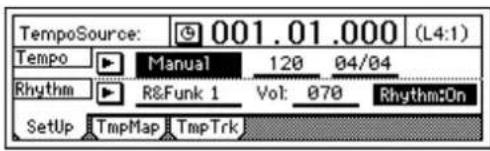
Note For more about "Tempo," "Beat," and "SelRhythm," refer to "1. Selecting and playing a rhythm" (→p.48).
Tempo map
Tempo maps let you change the tempo, time signature, or rhythm pattern at the various specified measures. By using tempo maps to change rhythm patterns, you can create a drum track for the entire song, including an intro, breaks, fill-ins, and an ending.
① Using Tempo Map as the tempo source.
- Access the [RHYTHM] "SetUp" tab page.
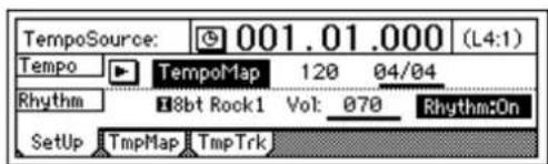
- Select "TempoSource," and turn the [VALUE] dial to choose "TempoMap."
② Specify tempo map "001" at the beginning of the song.
- Access the [RHYTHM] "TmpMap" tab page.
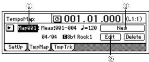
- Select "TempoMap," and turn the [VALUE] dial to choose tempo map "001."
Note Tempo map "001" specifies the tempo at the beginning of the song, and tempo maps "002"- "200" can be used to change the tempo at subsequent measures.
- Select the "Edit" button, and access the "Select TempoMap001 Param" dialog box.
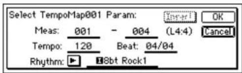
- Specify the tempo in "Tempo," the time signature in "Beat," and the rhythm pattern in "Rhythm."
- Use the ending measure of "Meas" to specify the number of measures that tempo "001" will continue.
note The starting measure of tempo map "001" cannot be changed from measure "001."
- When you have finished making settings, press the [YES/OK] key.
③ Create a new tempo map to change the tempo, time signature, and rhythm pattern during the song.
- Select the "New" button and press the [ENTER] key. The display will read "Select TempoMap002 Param."
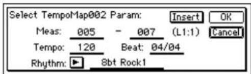
- Specify the "Tempo," "Beat," and "Rhythm" settings that you want to use for this new tempo map.
- Use "Meas" to specify the starting measure and ending measure at which tempo map "002" will be inserted.
- Pr ess the [YES/OK] key to add the tempo map. When you add a tempo map, any subsequent tempo maps will be renumbered upward, so that they are always numbered consecutively from the beginning of the song to the end of the song.
- By adding tempo maps, you can create drum patterns for an entire song, including an intro, breaks, fill-ins, and an ending.
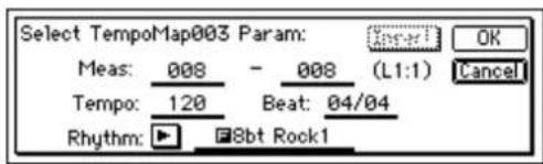
④ Listen to the tempo maps you created. In the [RHYTHM] "SetUp" tab page, set "Tempo-Source" to "TempoMap." In the [RHYTHM] tab page, set "Rhythm:On."
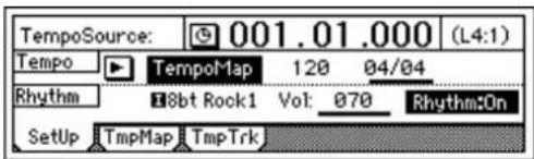
Move to the beginning of the song, and press the [PLAY] key to play back the song. The rhythm pattern and tempo will change according to the tempo maps that you created.
You can also check the tempo maps in the [SONG] "SelSong" tab page.
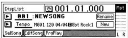
note If you want to record the sound of the rhythm as played by the tempo maps you created, refer to "3. Recording the rhythm" ( p.48).
Editing a tempo map
If you increase the number of measures, the measure numbers of subsequent tempo maps will move backward by the corresponding length. If you decrease the number of measures, the measure numbers of subsequent tempo maps will move forward by the corresponding length.
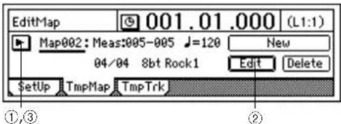
① Select the tempo map that you want to edit.
- Display the tempo map list, and select the tempo map that you want to edit.
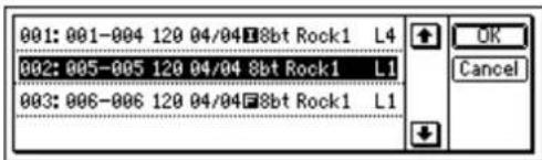
② Edit the settings.
- Select the "Edit" button. A dialog box will appear.
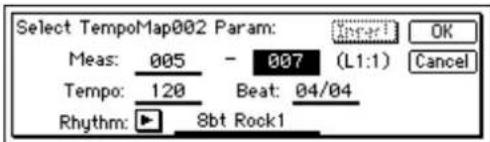
- Edit the parameters, and press the [YES/OK] key.
③ Verify that you have made the settings you want.
- Display the tempo map list, and check the tempo map.
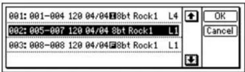
Adding a tempo map to insert a rhythm pattern
If you want to create a new tempo map, press the "Insert" button.
A tempo map will be inserted at the specified measure, and the measure numbers of subsequent tempo maps will move backward by the corresponding number of measures.
① Check the location at which you want to insert the tempo map.
- Display the tempo map list, and check the current tempo map. In this example, we will insert a tempo map at the beginning of the song.
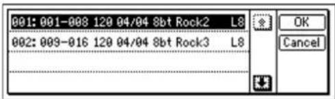
② Create a new tempo map.
- Select the "NEW" button and press the [ENTER] key to open the dialog box.
- Set the parameters.
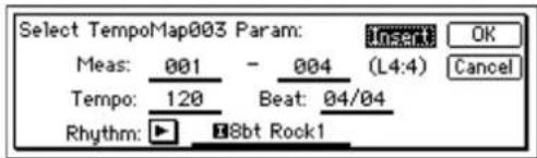
- T urn the "Insert" button "On," and press the [YES/OK] key.
③ Verify that the tempo map was inserted correctly.
- Display the tempo map list, and check the tempo map.
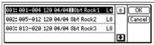
Overwriting a tempo map
If you want to add a tempo map to replace the rhythm pattern, turn off the "Insert" button when you create the new tempo map.
The tempo map of the specified measure(s) will be replaced, but the overall number of measure will not change.
① Verify the location at which you want to insert a tempo map.
- Display the tempo map list, and check the current tempo map.
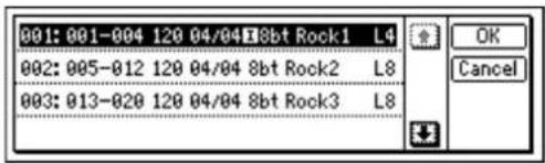
② Create the new tempo map.
- Select the "NEW" button and press the [ENTER] key to open the dialog box.
- Set the parameters.
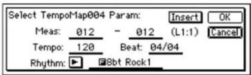
- T urn the "Insert" button "Off," and press the [YES/OK] key.
③ Verify that the tempo map was replaced as you expected.
- Display the tempo map list, and check the tempo map.
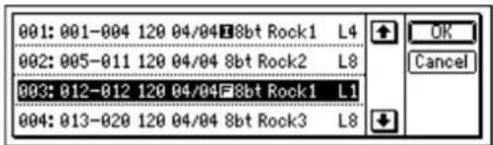
Deleting a tempo map
The maps located after the deleted map will move forward by the number of measures that were deleted.
① Select the tempo map that you want to delete.
- Display the tempo map list, and select the appropriate tempo map.
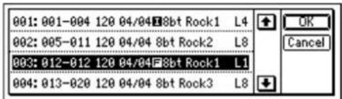
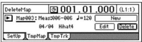
② Delete the tempo map.
- Select the "Delete" button. A message of "Are You Sure?" will ask you to confirm.
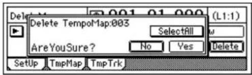
- Press the [YES/OK] key, and the selected tempo map will be deleted.
Note If you turn the "Select All" button "On," all maps other than "001" will be deleted, and the settings of map "001" will also be deleted.
③ Verify that the tempo map was deleted.
- Display the tempo map list, and verify that the map was deleted.
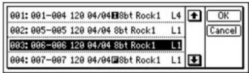
This operation cannot be undone.
- If you want to edit the tempo map, select the "Edit" button and press the [ENTER] key to open the dialog box. Edit the parameters as necessary. Press the [YES/OK] key to accept the new settings.
Tempo track
The tempo track records MIDI clock data from an external MIDI sequencer, or tap tempo data.
Recording MIDI Clock data from an external MIDI sequencer, and using it as the tempo track
Here's how MIDI Clock data from an external MIDI sequencer can be recorded as tempo data on the tempo track. You can use this when you want to synchronize a D1200 song with song data created on a MIDI sequencer in which the tempo changes continuously.
① Specify the time signature of the song.
If the time signature of the song data created on your MIDI sequencer changes during the song, create a new tempo map that begins where the time signature changes. (-p.49)
If you want the time signature to change during the song, you must create tempo maps accordingly. Tempo settings will play back in synchronization, but measures will become incorrectly aligned if the time signature changes do not match.
② Connect the MIDI OUT connector of your MIDI sequencer to the D1200's [MIDI IN] connector.
③ Set your MIDI sequencer so that it will transmit MIDI Clock messages.
Refer to the owner's manual of your MIDI sequencer.
④ Select how tempo will be recorded.
In the [RHYTHM] "TmpTrk" tab page, select "MIDI Clock."
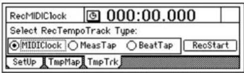
⑤ Record the MIDI Clock data.
- Press the "RecStart" button and press the [ENTER] key to put the D1200 in record-ready mode.
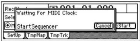
- Start your MIDI sequencer. - When the MIDI Clock data from the MIDI sequencer begins arriving, the display will indicate "Receiving-MIDIClock."
⑥ When the MIDI sequencer has finished playing, stop the MIDI sequencer.
When recording is completed on the D1200, the display will indicate "Complete." Press the [YES/OK] key.
⑦ Select the Tempo Track as the tempo source.
- Access the [RHYTHM] "SetUp" tab page.
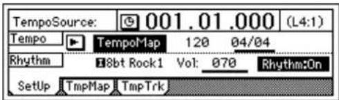
- Select "TempoSource," and turn the [VALUE] dial to specify "TempoTrk."
note If MIDI Clock data was not received correctly from your MIDI sequencer, recording may stop in the middle of the song.
Tap tempo
You can record the tempo by pressing (tapping) the [PLAY] key at the beginning of each measure or on each beat while the song plays.
note You can use a PS-1 foot switch (sold separately) instead of the [PLAY] key.
Tap tempo lets you record the tempo after a song has already been recorded. If you record tempo for a song for which you did not originally specify the tempo, you will be able to do the following things.
- Edit tracks in units of measures - Connect and synchronize external MIDI devices
① Prepare the audio for which you want to record the tempo. Record the audio from the beginning of the song.
note When recording from the beginning of the song, it is convenient to use Trigger recording. (→p.54)
② Specify the time signature of the song. If the time signature changes during the song for which you want to record tempo, create a tempo map at the location where the time signature changes.
If you want the time signature to change during the song, you must create the appropriate tempo maps. Tempo settings will play back in synchronization, but measures will become incorrectly aligned if the time signature changes do not match.
③ If you want to use a foot switch to input the tap tempo, connect an optional PS-1 foot switch to the [FOOT SWITCH] jack of the D1200.
④ Choose how you will record the tempo. In the [RHYTHM] "TmpTrk" tab page, select either "MeasTap" (tap at the beginning of each measure) or "BeatTap" (tap at each beat).
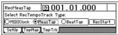
⑤ Record the tap tempo track.
- Select the "RecStart" button and press the [ENTER] key. The D1200 will enter the record-ready mode.
![Rec TempoTrack: MeasTap StartTap=[PLAY]orFootSw Cancel Start Setup TmpMap TmpTrk](/content/2026/05/820878/images/edc84d68be8f16919aec96ad616daba14e5fef9b7a02a49148900920492e2c54.jpg)
- When you press the [PLAY] key or a connected foot switch, the song will begin playing, and tap tempo recording will also begin. - While you listen to the playback, record the tap tempo by pressing the [PLAY] key or foot switch at the intervals you specified in step ④. The counter will be displayed while you record the tap tempo.
![Recording Tempo Track: Meas:003 EndTap=[STOP]](/content/2026/05/820878/images/9c74558d3aac0671614d363b1a648d303bba4a53805d41bc6ca63e119dbb8a16.jpg)
When using the [PLAY] key to record tap tempo, do not strike the key any more forcefully than necessary. Doing so may damage the hard disk etc.
⑥ After you have input the last tap, press the [STOP] key. For example if you are inputting four measures of a 4/4 time signature, tap four times in the case of "MeasTap" or sixteen times in the case of "BeatTap" to input up to the beginning of the fifth measure. Then press the [STOP] key. If you input taps only until mid-way through the song, the tempo of the last-input measure or beat will be automatically copied to the end of the song.
⑦ Specify the tempo track as the tempo source. Access the [RHYTHM] "SetUp" tab page, select "TempoSource," and turn the [VALUE] dial to choose "TempoTrk." Move to the beginning of the song, and press the [PLAY] key to play back the song and check the tempo.
The Recorder
1. Recording
You can connect audio sources such as guitar and keyboard to the input jacks, make mixer settings to assign these audio input sources to tracks of the recorder, and then record them. The D1200 has twelve recording/playback tracks, and each of the twelve tracks has eight virtual tracks.
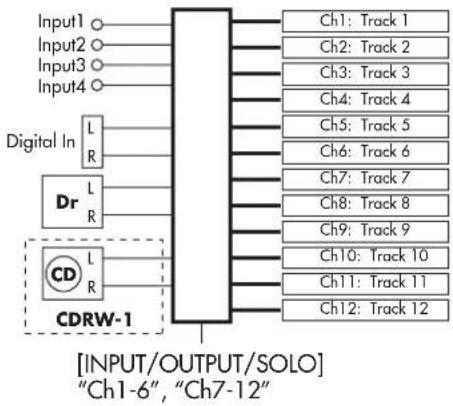
flowchart
graph TD
    A["Input1"] --> B["Block"]
    C["Input2"] --> B
    D["Input3"] --> B
    E["Input4"] --> B
    F["Digital In"] --> G["L R"]
    H["Dr"] --> I["L R"]
    J["CD"] --> K["L R"]
    L["CDRW-1"] --> M["Block"]
    N["Ch1: Track 1"] --> B
    O["Ch2: Track 2"] --> B
    P["Ch3: Track 3"] --> B
    Q["Ch4: Track 4"] --> B
    R["Ch5: Track 5"] --> B
    S["Ch6: Track 6"] --> B
    T["Ch7: Track 7"] --> B
    U["Ch8: Track 8"] --> B
    V["Ch9: Track 9"] --> B
    W["Ch10: Track 10"] --> B
    X["Ch11: Track 11"] --> B
    Y["Ch12: Track 12"] --> B
    Z["[INPUT/OUTPUT/SOLO"]] --> AA["Ch1-6", "Ch7-12"]
The following pages explain how to record audio on these tracks.
1-1. Basic recording
Here's how to record the audio signal that you specified in "1. Inputting audio to the mixer" (→p.35).
note If you want to create a new song for recording, set refer to "1-1. Creating a new song" (→p.31).
① Check the recording mode. Access the [BOUNCE] "RecMode" tab page. Set "Select RecMode" to "Input" (=record the input audio).
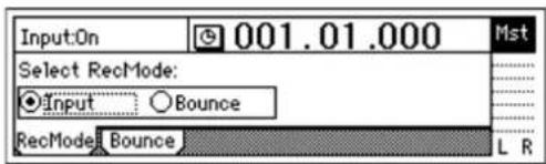
② Press the [TRACK STATUS] key for the track that you want to record, to set the status to REC (LED lit red).
③ Use the [CHANNEL] fader to set the recording level.
- Press the [METER/TRACK VIEW] key.
- Select the "button and press the [ENTER] key to select "PostFaderLev," and press the [YES/OK] key.
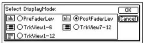
- Slowly raise the [CHANNEL] fader, and the level meter of the input channel will move according to the level of the input signal. Adjust the level to be as
high as possible without allowing the level bar to reach "CLP."
④ Move the counter location to the point in the song where you want to begin recording. (→p.32)
Start recording from the beginning of the song ("001.01.000" or "000:00.000").
⑤ Press the [REC] key (the [REC] and [PLAY] LEDs will blink).
⑥ Press the [PLAY] key (the [REC] and [PLAY] LEDs will light).
Begin performing on your instrument.
⑦ When you are finished performing, press the [STOP] key (the [REC] and [PLAY] LEDs will go dark). Listen to the playback to verify that your performance was recorded correctly.
1-2. Switching the virtual track for recording
The D1200 has twelve tracks, and each of these provides eight virtual tracks, labeled a-h.
For example when you record a solo part, you can record two or more "takes," each on their own virtual track, and select the best one later. Or when bounce-recording (ping-pong recording), you can specify two unrecorded virtual tracks as the recording-destination, allowing you to combine twelve tracks of data into two tracks without erasing any existing tracks. (→p.64)
Recording on a different virtual track
① Select a virtual track.
In the [TRACK] "Vtr1-6" or "Vtr7-12" tab page, select the track that you want to record, and turn the [VALUE] dial to select an unrecorded virtual track.
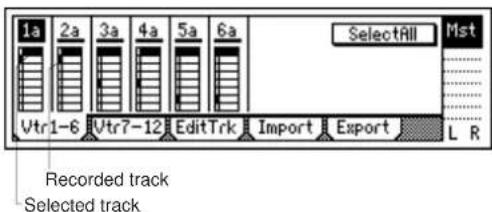
② Adjust the recording level of the input device, and record.
Refer to "1-1. Analog input" (→ p.35).
1-3. Recording while you listen to other tracks play
The process of recording while you listen to other tracks play is called "overdubbing." For example you can use this to record a solo while listening to previously-recorded backing tracks.
① Check the recording mode. Access the [BOUNCE] "RecMode" tab page. For "Select RecMode," choose "Input" (= record the audio input).
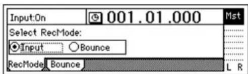
② Use the [CHANNEL] fader to set the recording level. Refer to "1-1. Basic recording."
③ Select the playback tracks.
Press the [TRACK STATUS] keys of the tracks that you want to hear, and set them to PLAY (LED lit green).
④ Select the recording track.
Press the [TRACK STATUS] key of the track that you want to record, to set it to REC (LED blinking red).
⑤ Mute tracks that you do not want to use.
For each track that you do not want to play or record, press the [TRACK STATUS] key to set it to MUTE (LED dark), so that no sound will be output by tracks that you are not using.
⑥ Adjust the recording level of the input device, and record.
Refer to "1-1. Analog input" ( p.35).
Trigger recording procedure
Trigger recording is a function that initiates recording when the input volume reaches a specified level.
① Connect your input device, select a track for recording, and adjust the recording level. Refer to "1-1. Basic recording" ( p.53).
② Access the [TRIGGER] "Trigger" tab page, and turn "TriggerRec" "On" (the [TRIGGER] key will light).
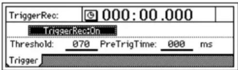
③ Press the [REC] key to select record-ready mode (LED blinking).
④ Begin playing your instrument.
When the input signal exceeds the threshold level ("Threshold"), recording will begin automatically.
⑤ When you are finished playing, press the [STOP] key to stop recording.
1-4. Re-recording a specific area: Punch-in/out
If you make just one mistake in a recorded performance, or are not satisfied with a portion of the performance, you can use "punch-in/out" recording to fix just that portion without having to re-record from the beginning of the song. "Punch-in" is the action of switching the song from the playback to the record mode, and "punch-out" is the action of switching from the record mode back to the playback mode.
Manual punch-in/out
Here's how you can punch-in and punch-out manually. During playback, press the [REC] key or an optional PS-1 foot switch to begin recording, and then press the [REC] key, [PLAY] key, or foot switch to stop recording.
① Connect your input device, select a track for recording, and adjust the recording level. Refer to "1-1. Basic recording" ( p.53).
② Specify the monitor output.
- Access the [INPUT/OUTPUT/SOLO] "Monitor" tab page.
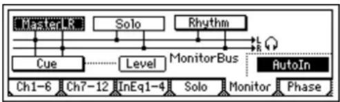
flowchart
graph TD
    A["MasterLR"] --> B["Solo"]
    B --> C["Rhythm"]
    C --> D["L"]
    D --> E["AutoIn"]
    F["Cue"] --> G["Level"]
    G --> H["MonitorBus"]
    H --> I["AutoIn"]
    J["Ch1-6"] --> K["Ch7-12"]
    K --> L["InEq1-4"]
    L --> M["Solo"]
    M --> N["Monitor"]
    N --> O["Phase"]
- Select the signal that you want to monitor. - T urn on the "AutoIn" button.
③ Move the counter to a location slightly before the point where you want to begin re-recording. (→p.32)
④ Press the [PLAY] key to begin playback. You will hear the recorded tracks play, including the recording-destination track.
⑤ At the point you want to begin re-recording, press the [REC] key.
Recording will begin (manual punch-in). Now you will hear the external input source.
⑥ At the point you want to stop re-recording, press the [REC] key or [PLAY] key.
Recording will stop, and playback will resume (manual punch-out). Now you will again hear the track play-back.
⑦ Press the [STOP] key to stop.
When you have finished recording, move the current location to a point slightly earlier than where you began recording, and listen to the re-recorded performance.
Using a foot switch for manual punch-in/out
You can switch between playback and recording by pressing a PS-1 foot switch (sold separately).
This lets you punch-in/out while you perform, or when the D1200 is located at a distance.
① Connect a foot switch to the [FOOT SWITCH] jack.
② Access the [SYSTEM/USB] "Control" tab page.
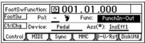
③ Specify the function of the foot switch.
Set "Func (FootSwFunction)" to "PunchIn-Out."
④ Perform steps ⑤ and ⑥ of "Manual punch-in/out," but press the foot switch instead of the [REC] key. (You may use the foot switch and [REC] key in conjunction with each other.)
note You can also use the foot switch to record from the beginning of the song. To do so, set "Func" in step ③ to "Play/Stop."
At the beginning of the song, press the [REC] key (the LED will blink), and then press the foot switch to begin recording.
Auto punch-in/out
The auto punch-in/out function automatically performs a punch-in and punch-out at pre specified locations.
① Access the [AUTO PUNCH] "AtPunch" tab page. In the [AUTO PUNCH] "AtPunch" tab page, select the "Auto Punch" button, and press the [ENTER] key to turn it
"On." This turns on the auto punch-in/out recording. The [AUTO PUNCH] key will light.
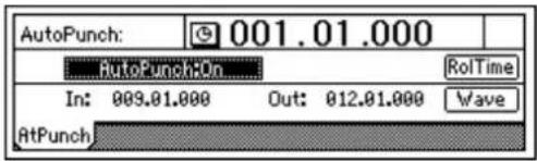
② Set the [IN/LOC1] point (punch-in) to specify the location where you want to begin recording, and set the [OUT/LOC2] point (punch-out) to specify the location where you want to stop recording. For details on how to register the [IN/LOC1] and [OUT/LOC2] locations, refer to "Registering a location to one of the Locate keys" (→p.33). In the [AUTO PUNCH] "AtPunch" tab page, you can select the "Wave" button and press the [ENTER] key to view the waveform, allowing you to set the IN and OUT points more accurately.
note The time locations you specify will overwrite the previously-specified locations for the [IN/LOC1] and [OUT/LOC2] keys.
③ Connect your input device, select a track for recording, and adjust the recording level. Refer to "1-1. Basic recording" (→p.53).
④ Specify the monitor output signal.
Refer to "Manual punch-in/out" ②. (→p.54)
⑤ Specify how much of the song will play before recording begins, and how much will play after recording ends. In the [AUTO PUNCH] "AtPunch" tab page, press the "RolTime" button and press the [ENTER] key to open the "SetRollTime" dialog box.
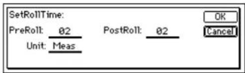
- T urn the [VALUE] dial to set "PreRoll" to the length that will play before recording begins, and set "PostRoll" to the length that will play after recording ends. Use "Unit" to select the unit by which to set to pre-roll and post-roll times. You can select either "Second" (seconds) or "Meas" (measures).
- When you have finished making your settings, press the [YES/OK] key to return to the previous page.
⑥ Begin recording.
- When you press the [REC] key, you will move to a point earlier than the specified punch-in point (by the distance of the pre-roll time), and enter record-ready mode (LED blinking).
- When you press the [PLAY] key, playback will begin. The track will play back during the pre-roll time, and recording will begin at the punch-in (IN) point. (The [REC] LED will be lit.)
⑦ Stop recording.
- Recording will stop when you reach the punch-out (OUT) point and switch to play back. (The [REC] LED will blink.)
• After the post-roll time has elapsed, playback will stop, and you will automatically return to the point specified by the pre-roll time.
⑧ Listen to the re-recorded results.
Loop recording
When using auto punch-in/out recording, you can switch the "Loop" function on so that the IN-OUT region will be recorded repeatedly (as a loop). When you are finished recording, you can use the Undo/Redo function to compare the takes that you recorded, and select the best one.
Loop recording procedure
① Make auto punch-in/out settings.
Refer to steps ①–⑤ of "Auto punch-in/out" (→p.54).
② In the [LOOP] "Loop" tab page, turn "Loop" "On."
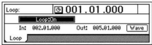
- When you press the [REC] key, you will move to the beginning of the pre-roll time, and enter record-ready mode. (The [REC] key LED will blink.)
- P r ess the [PLAY] key to begin playback. Playback will occur during the pre-roll time, and recording will begin when you reach the IN time. (The [REC] key LED will light.)
note When you reach the OUT time, recording will end and the post-roll region will play back. (The [REC] key LED will blink.)
Note When the post-roll time ends, you will automatically move to the beginning of the pre-roll time, and the same operations will be repeated.
- Press the [STOP] key at a point outside the recording area (IN–OUT) to stop.
④ Use the Undo/Redo function to compare the recorded content, and choose the best take.
- P r ess the [UNDO] key to display the Undo list. The Undo list shows "RecordTrack" for the most recent recording (Level00) and each preceding recording (Level (= the number of loops you recorded minus 1)).
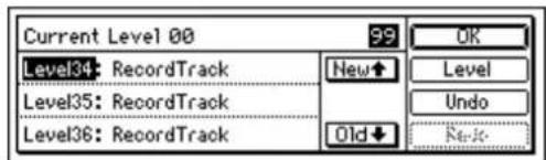
Recordings that you made before you performed loop recording will also appear in the list as "RecordTrack."
- From the Undo list, turn the [VALUE] dial to choose a recorded take. Then select the "Undo" button and press [ENTER]. The selected take will be recalled.
⑤ Listen to the recorded content.
- P r ess the [PLAY] key to play back, and listen to the recorded content. If "AutoPunch" is "On," playback will begin at the beginning of the pre-roll time, and continue to the end of the post-roll time.
- Repeat this procedure to find the best take. If you are satisfied with the selected take, press the [YES/OK] key to return to the previous screen.
Note If you want to select the most recent recording, select the "Redo" button and press the [ENTER] key to return to the "Level00" take.
2. Playback
This page explains how to perform basic playback, and how to use program playback.
2-1. Playback
① Select the track(s) that you want to play.
For each track that you want to play, press the [TRACK STATUS] key to set it to PLAY mode (LED lit green).
② Move to the counter location from which you want to play.
For details on how to move to a new location, refer to p.32.
③ Begin playback.
Press the [PLAY] key. (The [PLAY] LED will light.)
- Apply EQ to the playback. ( p.37)
- Adjust the level and pan of the playback. (→p.37)
- Apply effects to the playback. (→p.42)
- Play the built-in rhythm along with the playback. ( p.48)
④ Stop playback. Press the [STOP] key. (The [PLAY] LED will go dark.)
note Even if there is no more audio, playback will not stop until you press the [STOP] key.
note You can also use a PS-1 foot switch (sold separately) to start or stop playback (→p.101).
2-2. Program playback
This function lets you play two or more songs in the order you specify.
It is convenient to use this when recording to DAT or MD.
To create a program play list
① Access the [SONG] "PrgPlay" tab page.

② Select the song you want to play first.
Use the scroll buttons to select "01" in the program play list, and turn the [VALUE] dial to choose a song.
③ In the same way, select the second and following songs.
note To delete a song from the program play list, select that song and turn the [VALUE] until it reads “---”.
note The program play list will be preserved until you turn off the power.
To play back a song program list
① Access the [SONG] "PrgPlay" tab page.
② Press the [PLAY] key to begin playback.
The programs will play in the order of the list, starting with the first song.
During playback, you can press the [FF] key to move to the next song. Pressing the [REW] returns you to the beginning of the current song. If you are already at the beginning of the current song, pressing the [REW] key will move to the beginning of the previous song.
③ Press the [STOP] key to stop playback.
Note You can use "program list playback" only while the "PrgPlay" tab page is displayed.
2-3. Other types of playback
Playing back a different virtual track
As described in "1-2. Switching the virtual track for recording" (→p.53), select a virtual track that you recorded, and play it back.
Loop playback
This repeatedly plays the IN-OUT region of the song. This lets you check the contents of that region, or can be used in conjunction with auto-punch recording to perform loop recording. (→ p.54)
① Select the track(s) that you want to play.
For each track that you want to play, press the [TRACK STATUS] key to set it to PLAY mode (LED lit green).
② Register the region (IN-OUT) that you want to loop. (-p.33, 118)
These settings can also be made in [LOOP] "Loop" or in [AUTO PUNCH] "AtPunch" tab page "Wave."
③ Access the [LOOP] "Loop" tab page, and turn the "Loop" button "On."
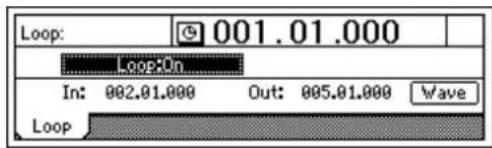
④ Begin loop playback.
When you press the [PLAY] key, playback will begin at the IN point, and the IN-OUT region will play repeatedly.
⑤ Press the [STOP] key to stop playback.
3. Track editing
You can use track editing commands to copy a track, insert blank space, erase a track, delete a track, reverse a track, optimize a track, exchange tracks, expand/compress a track, copy an entire track, exchange two entire tracks, create a fade-in/fade-out, or normalize the level.
In some cases, track editing may not be possible if there is insufficient space on the song drive. You will need to allocate enough free space for the track editing operation (equivalent to the IN-OUT or TO-END time).
3-1. Preparations for track editing
- In order to perform track editing, you must first register the region (the area of time) that you want to edit.
- Move to the counter location that you want to register.
- P r ess the [STORE] key, and then press one of the following keys to register the time in that key. (→p.33) [IN/LOC1] key: IN time [OUT/LOC2] key: OUT time [TO/LOC3] key: TO time [END/LOC4] key: END time
- Select a virtual track. (→p.53)
3-2. Track editing procedures
Copy a track: "CopyTrack"
This command copies the specified region (IN-OUT) of track data to another location (TO).
- The IN-OUT region can be copied once, or multiple times in succession.
- You can copy data from one track, or from multiple tracks simultaneously.
- By using the clipboard, you can copy track data to a different song.
Here are some ways in which you can use this command.
• Repeatedly copy a phrase of several measures (such as a drum pattern) to create a track that extends the entire length of song.
- Copy the first verse of a song to create the second verse.
- Record a favorite phrase from a track, and copy it to a different track or song.
Copying track data within the same song
Here's how the IN-OUT region of track 1 can be copied three times starting at the TO location of track 2.
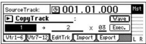
① Register the IN, OUT, and TO locations. (→ p.33, 118) Use the IN time to specify the beginning of the copy-source region, the OUT time to specify the end of the copy-source region, and the TO time to specify the location to which the data will be copied.
② Select "CopyTrack."
In the [TRACK] "EditTrk tab page, select "EditType" and use the [VALUE] dial to choose "CopyTrack."
③ Select the copy-source track number. Use "SourceTrack" to select track "1."
④ Select the copy-destination track number.
Use "DestTrack" to select track "2."
Note If you selected two or more tracks for "SourceTrack," you must specify the same number of tracks for "Dest-Track."
⑤ Specify the number of times that the data will be copied. Set "Times" to "3."
⑥ Select the "Exec." button and press the [ENTER] key. When the display asks "AreYouSure?," press the [YES/OK] key to execute the operation. When the operation has been completed, the display will indicate "Completed." Press the [YES/OK] key.
note The copied data will be overwritten onto the copy-destination track.
⑦ Check the results of the editing operation. Press the [TO/LOC3] key, and play back from the TO location to verify that the data was copied correctly. If you are not satisfied with the results, you can use Undo to return to the previous state. (→p.126)
Copying track data to a track in a different song
Here's how the IN-OUT region of track 1 in song 001 can be copied once to the TO location of track 2 in song 002.
![SourceTrack: 001.01.000 Mst CopyTrack : Wave 1 → Clip1 × 01 Exec. Vtr1-6 [Vtr7-12] EditTrk Import Export L R](/content/2026/05/820878/images/8415c125cc57f159383873d2ea6f0724f2a218a3eaa03d859b930e6b67fdc381.jpg)
① Select song 001.
② Register the IN and OUT locations. (→p.33, 118)
③ Select "CopyTrack."
In the [TRACK] "EditTrk tab page, select "EditText" and use the [VALUE] dial to choose "CopyTrack."
④ Select the copy-source track number. Use "SourceTrack" to select track "1."
⑤ Select the clipboard as the copy-destination track. Use "DestTrack" to select "Clip."
⑥ Select the "Exec." button and press the [ENTER] key. When the display asks "AreYouSure?," press the [YES/OK] key to execute the operation. When the operation has been completed, the display will indicate "Completed." Press the [YES/OK] key.
note The copied data will overwrite the data in the clipboard.
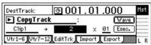
⑦ Select song 002.
⑧ Register the TO location. (→p.33, 118)
⑨ Select "CopyTrack."
In the [TRACK] "EditTrk tab page, select "EditText" and use the [VALUE] dial to choose "CopyTrack."
⑩ Select the clipboard as the copy-source track.
Set "SourceTrack" to "Clip1." The number indicates the number of tracks in the clipboard.
⑪ Select the copy-destination track number.
Use "DestTrack" to select track "2."
⑫ Specify the number of times that the data will be copied. Set "Times" to "1."
note If you selected two or more tracks for "SourceTrack," you must specify the same number of tracks for "DestTrack."
⑬ Select the "Exec." button and press the [ENTER] key. When the display asks "AreYouSure?," press the [YES/OK] key to execute the operation. When the operation has been completed, the display will indicate "Completed." Press the [YES/OK] key.
note The copied data will be overwritten onto the copy-destination track.
⑭ Check the results of the editing operation.
Press the [TO/LOC3] key, and play back from the TO location to verify that the data was copied correctly. If you are not satisfied with the results, you can use Undo to return to the previous state. ( p.126)
Insert blank space: "InsertTrack"
This command inserts blank space into the specified region (IN-OUT) of a recorded track. Track data following the inserted space will be shifted toward the end of the song.
- You can insert space into one or more tracks simultaneously.
This can be used in ways such as the following. - If you want to add a phrase to the middle of a recorded performance, insert a space of the appropriate length, and then record into that area.
Inserting blank space
Here's how to insert blank space into the IN-OUT region of track 1.
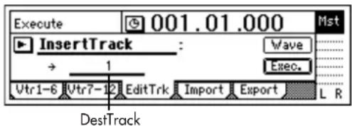
① Register the IN and OUT times. (→p.33, 118)
② Select "InsertTrack."
In the [TRACK] "EditTrk" tab page, select "EditType" and use the [VALUE] dial to choose "InsertTrack."
③ Select the track number into which the blank space will be inserted.
Use "DestTrack" to select track "1."
④ Select the "Exec." button and press the [ENTER] key. When the display asks "AreYouSure?," press the [YES/OK] key to execute the operation.
When the operation has been completed, the display will indicate "Completed." Press the [YES/OK] key.
⑤ Check the results of the operation. Press the [IN/LOC1] key, and play back from the IN location to verify that the operation did what you expected.
If you are not satisfied with the results, you can use Undo to return to the previous state. ( p.126)
Erase a track: "EraseTrack"
This command erases recorded data from the specified region (IN-OUT) of a track. The region will become blank. Unlike the Delete Track command, this Erase Track command does not move the data that follows the OUT time.
- You can erase data from the IN-OUT region of one or more tracks simultaneously.
Erasing data from a track
Here's how to erase the IN-OUT region of track 1.
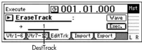
① Register the IN and OUT times. (→p.33, 118)
② Select "EraseTrack."
In the [TRACK] "EditTrk" tab page, select "EditType" and use the [VALUE] dial to choose "EraseTrack."
③ Select the track number from which data will be erased. Use "DestTrack" to select track "1."
④ Select the "Exec." button and press the [ENTER] key. When the display asks "AreYouSure?," press the [YES/OK] key to execute the operation.
When the operation has been completed, the display will indicate "Completed." Press the [YES/OK] key.
⑤ Check the results of the operation.
Press the [IN/LOC1] key, and play back from the IN location to verify that the operation did what you expected.
If you are not satisfied with the results, you can use Undo to return to the previous state. ( p.126)
Delete a track: "DeleteTrack"
This command deletes the specified region (IN-OUT) of a track. When an area is deleted, the subsequent data (following the OUT point) will be shifted toward the beginning of the song.
- You can delete data from the IN-OUT region of one or more tracks simultaneously.
Deleting data from a track
Here's how to delete the IN-OUT region of track 1.
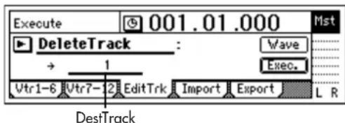
① Register the IN and OUT times. (→p.33, 118)
② Select "DeleteTrack."
In the [TRACK] "EditTrk" tab page, select "EditType" and use the [VALUE] dial to choose "DeleteTrack."
③ Select the track number from which data will be deleted. Use "DestTrack" to select track "1."
④ Select the "Exec." button and press the [ENTER] key. When the display asks "AreYouSure?," press the [YES/OK] key to execute the operation.
When the operation has been completed, the display will indicate "Completed." Press the [YES/OK] key.
⑤ Check the results of the operation. Press the [IN/LOC1] key, and play back from the IN location to verify that the operation did what you expected. If you are not satisfied with the results, you can use Undo to return to the previous state. ( p.126)
Reverse a track: "ReverseTrack"
This command copies the data in the specified region (IN-OUT) of the track "in reverse" (i.e., so that the data will play backward) and places it at the TO location, either in the same track or in another track.
- The data of the IN–OUT region can be copied one or more times in succession by a single operation.
- You can copy just one track, or multiple tracks of data at the same time.
Copying track data in reverse
Here's how the IN-OUT region of track 1 can be copied in reverse three times starting at the TO location of track 2.
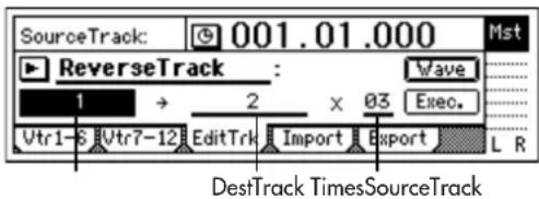
① Register the IN, OUT, and TO locations. (→ p.33, 118)
② Select "ReverseTrack."
In the [TRACK] "EditTrk tab page, select "EditMode" and use the [VALUE] dial to choose "ReverseTrack."
③ Select the reverse-source track number. Use "SourceTrack" to select track "1."
④ Select the reverse-destination track number. Use "DestTrack" to select track "2."
Note If you selected two or more tracks for "SourceTrack," you must specify the same number of tracks for "Dest-Track."
⑤ Specify the number of times that the data will be copied. Set "Times" to "3."
⑥ Select the "Exec." button and press the [ENTER] key. When the display asks "AreYouSure?," press the [YES/OK] key to execute the operation. When the operation has been completed, the display will indicate "Completed." Press the [YES/OK] key.
⑦ Check the results of the editing operation.
Press the [TO/LOC3] key, and play back from the TO location to verify that the operation produced the results you expect.
If you are not satisfied with the results, you can use Undo to return to the previous state. (→p.126)
Note As the specified region (IN-OUT) is set longer, it will correspondingly take longer for processing to be finished and for the "Completed" indication to appear..
Optimize a track: "OptimizeTrack"
This command removes noise and optimizes the recorded track data in the specified region (IN-OUT).
Optimizing track data
Here's how to optimize the IN-OUT region of track 1 so that "DiskBusy" warnings will no longer appear.
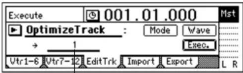
DestTrack
① Register the IN and OUT locations.
Set the IN point slightly ahead of where "DiskBusy" warnings start being displayed, and set the OUT point to a location where these warnings are no longer displayed. (→ p.33, 118)
② Select "Optimize."
In the [TRACK] "EditTrk" tab page, set "EditType" to "OptimizeTrack."
③ Select the optimize mode.
Select the "Mode" button and press the [ENTER] key to open the dialog box.
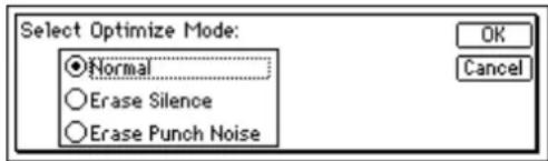
For this example, select "Normal" and press the [YES/OK] key to return to the [TRACK] "EditTrk" tab page.
④ Select the number of the track that you want to optimize.
Find the track whose data you suspect to be fragmented (here we will assume it is track 1), and set "DestTrack" to that track number ("1" in this example).
⑤ Select the "Exec." button and press the [ENTER] key. When the display asks "AreYouSure?," press the [YES/OK] key to execute the operation. When the operation has been completed, the display will indicate "Completed." Press the [YES/OK] key.
⑥ Check the results of the operation.
Press the [IN/LOC1] key, and play back from the IN location. If "Disk Busy" warnings are no longer displayed, and the data plays correctly, the data has been optimized successfully.
If you are not satisfied with the results, you can use Undo to return to the previous state. (→p.126)
Note As the specified region (IN-OUT) is set longer, it will correspondingly take longer for processing to be finished and for the "Completed" indication to appear.
Erasing silent audio events
Here's how to erase silent audio events from the IN-OUT region of track 1, turning them into blank space.
① Register the IN and OUT locations.
Set the IN point slightly ahead of the silent events you want to erase, and set the OUT point to a location slightly after these events. ( p.33, 118)
② Select "Optimize."
In the [TRACK] "EditTrk" tab page, set "EditType" to "OptimizeTrack."
③ Select the optimize mode.
Select the "Mode" button and press the [ENTER] key to open the dialog box.
For this example, select "Erase Silence" and press the [YES/OK] key to return to the [TRACK] "EditTrk" tab page.
④ Select the number of the track that you want to optimize.
For this example, set "DestTrack" to "1."
⑤ Select the "Exec." button and press the [ENTER] key. When the display asks "AreYouSure?," press the [YES/OK] key to execute the operation. When the operation has been completed, the display will indicate "Completed." Press the [YES/OK] key.
⑥ Check the results of the operation.
Press the [IN/LOC1] key, and play back from the IN location to hear the results.
If you are not satisfied with the results, you can use Undo to return to the previous state. (→p.126)
Note As the specified region (IN–OUT) is set longer, it will correspondingly take longer for processing to be finished and for the "Completed" indication to appear.
Erasing punch-in/out noise
Here's how to erase punch-in/out noise from the IN-OUT region of track 1.
① Register the IN and OUT locations.
Set the IN point slightly ahead of the noise you want to erase, and set the OUT point to a location slightly after the noise. ( p.33, 118)
note This editing can be performed only on the transition between events.
② Select "Optimize."
In the [TRACK] "EditTrk" tab page, set "EditType" to "OptimizeTrack."
③ Select the optimize mode.
Select the "Mode" button and press the [ENTER] key to open the dialog box.
For this example, select "Erase Punch Noise" and press the [YES/OK] key to return to the [TRACK] "EditTrk" tab page.
④ Select the number of the track that you want to optimize.
For this example, set "DestTrack" to "1."
⑤ Select the "Exec." button and press the [ENTER] key. When the display asks "AreYouSure?," press the [YES/OK] key to execute the operation. When the operation has been completed, the display will indicate "Completed." Press the [YES/OK] key.
⑥ Check the results of the operation.
Press the [IN/LOC1] key, and play back from the IN location to hear the results.
If you are not satisfied with the results, you can use Undo to return to the previous state. ( p.126)
Note As the specified region (IN-OUT) is set longer, it will correspondingly take longer for processing to be finished and for the "Completed" indication to appear.
Exchange tracks: "SwapTrack"
This command exchanges (swaps) recorded track data between the specified region (IN–OUT) and the corresponding region of another track.
- You can swap the data of one or more tracks simultaneously.
Swapping track data
Here's how to exchange the IN-OUT regions of track 1 and track 2.
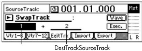
① Register the IN and OUT locations. (→p.33, 118)
② Select "SwapTrack."
In the [TRACK] "EditTrk" tab page, select "EditText" and use the [VALUE] dial to select "SwapTrack."
③ Select the swap-source track number. Set "SourceTrack" to track "1."
④ Select the swap-destination track number. Set "DestTrack" to track "2."
Note If you selected two or more tracks for "SourceTrack," you must specify the same number of tracks for "Dest-Track."
⑤ Select the "Exec." button and press the [ENTER] key. When the display asks "AreYouSure?," press the [YES/OK] key to execute the operation. When the operation has been completed, the display will indicate "Completed." Press the [YES/OK] key.
⑥ Check the results of the operation.
Press the [IN/LOC1] key, and play back from the IN location to verify that the operation produced the results you expect.
If you are not satisfied with the results, you can use Undo to return to the previous state. ( p.126)
Expand/compress a track: "Exp/CompTrack"
This command expands or compresses the specified region (IN-OUT) of recorded track data to fit the specified region (TO-END) of the specified track.
- The expanded or compressed data can be created in a different track, while preserving the original data.
• Y ou can specify whether to convert the pitch. - Y ou can simultaneously convert one or more adjacent tracks of data.
- The converted data can be copied one or more times in succession.
This command can be used in ways like the following.
- T o convert drum loops of differing tempo to the same tempo.
• T o make a phrase occupy a specific length of time.
Copying expanded/compressed track data
Here's how the IN-OUT region of track 1 can be converted to the length of the track 2 TO-END region without affecting the pitch, and copied there three times.
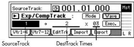
① Register the IN, OUT, TO, and END locations. ( p.33, 118)
② Select "Exp/CompTrack."
In the [TRACK] "EditTrk" tab page, select "EditTextType" and use the [VALUE] dial to choose "Exp/CompTrack."
③ Select the expansion/compression source track. Set "SourceTrack" to track "1."
④ Select the track to which the expanded/compressed data will be copied.
Set "DestTrack" to track "2."
Note: If you selected two or more tracks for "SourceTrack," you must specify the same number of tracks for "DestTrack."
⑤ Specify the number of times the data will be copied. Set "Times" to "3."
⑥ Select the expansion/compression mode.
Select the "Mode" button and press the [ENTER] key to open the dialog box.
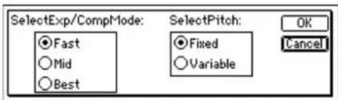
For this example, select "Fast" and "Fixed." Then select the "OK" button and press the [ENTER] key to return to the [TRACK] "EditTrk" tab page.
⑦ Select the "Exec." button and press the [ENTER] key. When the display asks "AreYouSure?," press the [YES/OK] key to execute the operation. When the operation has been completed, the display will indicate "Completed." Press the [YES/OK] key.
⑧ Check the results of the operation.
Press the [TO/LOC3] key, and play back from the TO location to verify that the operation produced the results you expect.
If you are not satisfied with the results, you can use Undo to return to the previous state. (→p.126)
Note As the specified region (IN-OUT) is set longer, it will correspondingly take longer for processing to be finished and for the "Completed" indication to appear.
Copy an entire track/Copying to a V-track (virtual track): "CopyWholeTrack"
This command copies an entire recorded track (from the beginning to the end) to another track.
• Y ou can copy one or more tracks simultaneously.
- Y ou can copy the currently selected V-track to other V-tracks.
This can be used in ways such as the following.
- You can copy a track to several virtual tracks, and use those tracks to create several different takes.
Copying an entire track
Here's how to copy track 1 to V-track "a" (=currently selected) of track 2.
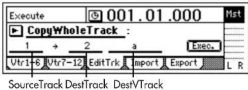
① Select "CopyWholeTrack."
In the [TRACK] "EditTrk" tab page, select "EditType" and use the [VALUE] dial to choose "CopyWholeTrack."
② Select the copy-source track number. Set "SourceTrack" to track "1."
③ Select the copy-destination track number. Set "DestTrack" to track "2."
note If you selected two or more tracks for "SourceTrack," you must specify the same number of tracks for "DestTrack."
④ Select the copy destination V-track. Set "DestVTrack" to V-track "a."
⑤ Select the "Exec." button and press the [ENTER] key. When the display asks "AreYouSure?," press the [YES/OK] key to execute the operation. When the operation has been completed, the display will indicate "Completed." Press the [YES/OK] key.
⑥ Check the results of the operation.
Play back the song from the beginning to verify that the data was copied as you expect.
If you are not satisfied with the results, you can use Undo to return to the previous state. (→ p.126)
Copying to a V-track
Here's how to copy V-track "a" (=currently selected) of track 1 to V-track "b" of track 1.
① Check the copy-destination.
In the [TRACK] "Vtr1-6" tab page, check that track 1 V-track "b" is empty or is a track that you do not need to keep. Then be sure to return the V-track selection to "a." (→p.108)
② Select "CopyWholeTrack."
In the [TRACK] "EditTrk" tab page, select "EditType" and use the [VALUE] dial to choose "CopyWholeTrack."
③ Select the copy-source track number. Set "SourceTrack" to track "1."
④ Select the copy-destination track number. Set "DestTrack" to track "1."
note If you selected two or more tracks for "SourceTrack," you must specify the same number of tracks for "DestTrack."
⑤ Select the copy destination V-track. Set "DestVTrack" to V-track "b."
⑥ Select the "Exec." button and press the [ENTER] key. When the display asks "AreYouSure?," press the [YES/OK] key to execute the operation. When the operation has been completed, the display will indicate "Completed." Press the [YES/OK] key.
⑦ In the [TRACK] "Vtr1-6" tab page, select V-track "b" for track 1.
⑧ Check the results of the operation.
Play back the song from the beginning to verify that the data was copied as you expect.
If you are not satisfied with the results, you can use Undo to return to the previous state. (→p.126)
In this case, return the track 1 V-track selection to "a."
Exchange two entire tracks: "SwapWholeTrack"
This command exchanges an entire track of recorded data (from the beginning to the end) with another track.
- You can exchange one or more tracks in a single operation.
This can be used in ways such as the following. - Rearrange recorded tracks to organize them by type.
- Rearrange data that extends across differing V-tracks so that each track uses (for example) V-track "a."
Swapping an entire track
Here's how to swap track 1 with the V-track "a" that is currently selected for track 2.
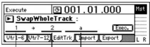
DestTrack DestVTrackSourceTrack
① Select "SwapWholeTrack."
In the [TRACK] "EditTrk" tab page, select "EditTextType" and use the [VALUE] dial to choose "SwapWhole Track."
② Select the swap-source track number. Set "SourceTrack" to track "1."
③ Select the swap-destination track number. Set "DestTrack" to track "2."
note If you selected two or more tracks for "SourceTrack," you must specify the same number of tracks for "DestTrack."
④ Select the swap-destination V-track. Set "DestVTrack" to V-track "a."
⑤ Select the "Exec." button and press the [ENTER] key. When the display asks "AreYouSure?," press the [YES/OK] key to execute the operation. When the operation has been completed, the display will indicate "Completed." Press the [YES/OK] key.
⑥ Check the results of the operation.
Play back the song from the beginning to verify that the data was swapped as you expect.
If you are not satisfied with the results, you can use Undo to return to the previous state. (→p.126)
Swapping with a V-track
Here's how to swap the currently selected track 1 V-track "a" with track 1 V-track "b."
① Check the copy-destination.
In the [TRACK] "Vtr1–6" tab page, check that track 1 V-track "b" is the track that you want to exchange. Then be sure to return the V-track selection to "a." (→p.108)
② Select "SwapWholeTrack."
In the [TRACK] "EditTrk" tab page, select "EditType" and use the [VALUE] dial to choose "SwapWholeTrack."
③ Select the swap-source track number. Set "SourceTrack" to track "1."
④ Select the swap-destination track number. Set "DestTrack" to track "1."
Note If you selected two or more tracks for "SourceTrack," you must specify the same number of tracks for "Dest-Track."
⑤ Select the swap-destination V-track. Set "DestVTrack" to V-track "b."
⑥ Select the "Exec." button and press the [ENTER] key. When the display asks "AreYouSure?," press the [YES/OK] key to execute the operation. When the operation has been completed, the display will indicate "Completed." Press the [YES/OK] key.
⑦ In the [TRACK] "Vtr1-6" tab page, select V-track "b" for track 1.
⑧ Check the results of the operation.
Play back the song from the beginning to verify that the data was swapped as you expect.
If you are not satisfied with the results, you can use Undo to return to the previous state. (→p.126)
In this case, return the track 1 V-track selection to "a."
Create a fade-in/fade-out: "FadeTrack"
This command fades-in or fades-out the specified region (IN-OUT) of recorded track data. By using both of these operations, you can create cross-fades.
- Y ou can fade-in or fade-out the IN-OUT region.
- You can fade-in or fade-out one or more tracks simultaneously.
Fading-in
Here's how to fade-in the IN-OUT region of track 1.
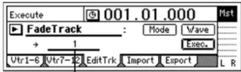
DestTrack
① Register the IN and OUT locations.
Register the locations at which you want the fade-in to start and end. ( p.33, 118)
② Select "FadeTrack."
In the [TRACK] "EditTrk" tab page, select "EditType" and use the [VALUE] dial to choose "FadeTrack."
③ Select the fade-in destination track number. Set "DestTrack" to track "1."
④ Select the fade-in curve.
Select the "Mode" button and press the [ENTER] key to open the dialog box.
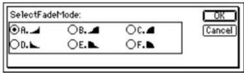
For this example, select curve "A" and press the [YES/OK] key to return to the [TRACK] "EditTrk" tab page.
⑤ Select the "Exec." button and press the [ENTER] key. When the display asks "AreYouSure?," press the [YES/OK] key to execute the operation. When the operation has been completed, the display will indicate "Completed." Press the [YES/OK] key.
⑥ Check the results of the operation.
Press the [IN/LOC1] key and play back from the IN location to verify that the fade-in was created as you expect.
If you are not satisfied with the results, you can use Undo to return to the previous state. (→p.126)
As the specified region (IN-OUT) is set longer, it will correspondingly take longer for processing to be finished and for the "Completed" indication to appear.
Fading-out
Here's how to fade-out the IN-OUT region of track 1.
① Register the IN and OUT locations.
Register the locations at which you want the fade-out to start and end. (→p.33, 118)
② Select "FadeTrack."
In the [TRACK] "EditTrk" tab page, select "EditType" and use the [VALUE] dial to choose "FadeTrack."
③ Select the fade-out curve.
A., B., C.: fade-in curves
D., E., F.: fade-out curves
Select the "Mode" button and press the [ENTER] key to open the dialog box. For example, select curve "D" and press the [YES/OK] key to return to the [TRACK] "Edit-Trk" tab page.
Note If you selected two or more tracks for "SourceTrack," you must specify the same number of tracks for "DestTrack."
④ Select the fade-out destination track number. Set "DestTrack" to track "1."
⑤ Select the "Exec." button and press the [ENTER] key. When the display asks "AreYouSure?," press the [YES/OK] key to execute the operation. When the operation has been completed, the display will indicate "Completed." Press the [YES/OK] key.
⑥ Check the results of the operation.
Press the [IN/LOC1] key and play back from the TO location to verify that the fade-out was created as you expect.
If you are not satisfied with the results, you can use Undo to return to the previous state. (→p.126)
As the specified region (IN-OUT) is set longer, it will correspondingly take longer for processing to be finished and for the "Completed" indication to appear..
Normalize the level: "NormalizeTrack"
In cases where the recorded level is low, this command can boost the specified region (IN-OUT) of recorded track data to the maximum volume that will not cause clipping.
- This command searches for the peak value of the audio data within the IN-OUT region, and boosts the overall level of all the audio data in the IN-OUT region so that the peak value reaches the maximum level.
- You can normalize the data of one or more adjacent tracks simultaneously.
Note If you normalize data that was recorded at an extremely low level, any noise included in that region will also be boosted.
Normalizing the level
Here's how to normalize the IN-OUT region of track 1.
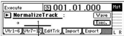
DestTrack
① Register the IN and OUT locations.
Register the locations at which you want normalization to start and end. ( p.33, 118)
② Select "NormalizeTrack."
In the [TRACK] "EditTrk" tab page, select "EditType" and use the [VALUE] dial to choose "NormalizeTrack."
③ Select the number of the track that will be normalized. Set "DestTrack" to track "1."
④ Select the "Exec." button and press the [ENTER] key. When the display asks "AreYouSure?," press the [YES/OK] key to execute the operation. When the operation has been completed, the display will indicate "Completed." Press the [YES/OK] key.
⑤ Check the results of the operation.
Press the [IN/LOC1] key and play back from the IN location to verify that the data was normalized as you expect.
If you are not satisfied with the results, you can use Undo to return to the previous state. (→p.126)
Note As the specified region (IN-OUT) is set longer, it will correspondingly take longer for processing to be finished and for the "Completed" indication to appear.
Mastering
This section explains how you can adjust mixer parameters such as EQ, fader, and effects for each recorded audio track to combine the tracks into a two-track stereo mix, and record the mix on the D1200, or onto an external two-channel recorder (e.g., DAT recorder, MD recorder, cassette tape recorder) as a finished song. This mix can also be used to create an audio CD using the optional CDRW-1.
1. Bounce-recording
You can use bounce-recording to combine multiple tracks into two tracks. Use this when you want to master your song and create an audio CD.
Instead of mastering your completed song to an external two-track recorder, saving your master on two tracks of the D1200 is also a good option.
You can use bounce-recording to do the following.
- Combine twelve tracks of audio, and overwrite-record them on two tracks.
- Combine twelve tracks of audio, and record them on two currently-unused virtual tracks.
- Combine ten tracks of audio with two external audio input sources, and record them on the remaining two tracks.
Note After recording or track editing, you can use the Undo function to return to the state prior to recording or track editing. (→p.126)
If you record to virtual tracks, check the selected virtual tracks after executing Undo.
1-1. Combining multiple tracks into two tracks
Combining twelve tracks of audio and overwrite-recording them on two tracks
Here's how to combine the audio of tracks 1–12 and overwrite-record the mix onto tracks 1 and 2.
① Select bounce-recording as the recording mode.
- Access the [BOUNCE] "RecMode" tab page.
- Select "Bounce."
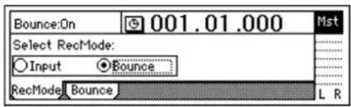
② Select the bounce mode.
- Access the [BOUNCE] "Bounce" tab page.
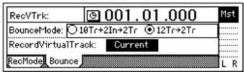
- Select "12Tr→2Tr" as the "BounceMode."
③ Specify that the currently-selected tracks will be used for recording.
Set "RecordVirtualTrack" to "Current."
④ Select the tracks on which you will record.
Set the recording track (1 and 2) status to REC (LED lit red). Set the remaining tracks (3–12) to PLAY (LED lit green).
⑤ Adjust the pan of the playback tracks.
Press the [PLAY] key to play back, and turn the [PAN] and [BALANCE] knobs to adjust the stereo positions of tracks 1–12.
⑥ Adjust the playback and recording levels.
Use the [CHANNEL] faders to adjust the playback levels.
- Press the [METER/TRACK VIEW] key.
- Select the "button and press the [ENTER] key to open the dialog box. Select "PostFaderLev" so that you can view meters for the faders.
⑦ Use the [MASTER] fader to adjust the recording level. When you have finished making adjustments, press the [STOP] key.
⑧ Move the current time to the beginning of the song. (→p.32)
⑨ Begin bounce-recording.
Press the [REC] key to enter record-ready mode (LED blinking), and press the [PLAY] key to begin recording (LED lit).
⑩ When you are finished recording, press the [STOP] key to stop.
⑪ Check the recorded results.
- Press the [TRACK STATUS] keys of the recording tracks (1 and 2) to set them to PLAY (LED lit green).
- Either lower the faders of the remaining channels, or go to the [INPUT/OUTPUT/SOLO] "Solo" tab page and turn "1-2" "On."
- Press the [PLAY] key to listen to the playback, and then press the [STOP] key to stop.
Combining twelve tracks of audio and recording them on two currently-unused virtual tracks
Here's how to combine the audio of tracks 1–12 (virtual track "a" selected for all tracks) and record the mix onto virtual track "b" of tracks 1 and 2.
○ Perform bounce-recording as described in "Combining twelve tracks of audio and overwrite-recording them on two tracks." However in step ③, select "b" for "Record VirtualTrack," so that the mix is recorded onto virtual track "b."
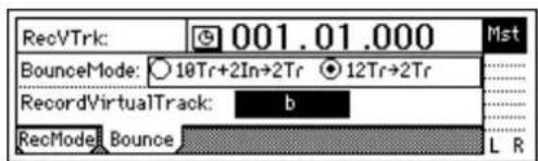
To hear the bounce-recorded result, select virtual track "b" and play back.
Access the [TRACK] "Vtr1-6" tab page, and for tracks 1 and 2, set "SelectVirtualTrack" to "1b" and "2b."
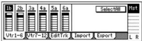
Combining ten tracks of audio and two external audio sources and recording them on the two remaining tracks
Here's how to combine the audio of tracks 1–10 with external audio input sources from INPUT 1 and 2, and record the mix on tracks 11 and 12.
① Specify the input channels.
- Access the [INPUT/OUTPUT/SOLO] "Ch7-12" tab page.
- Assign "INPUT 1" to "Ch11," and "INPUT 2" to "Ch12."
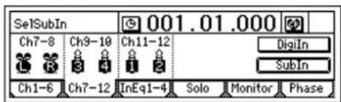
② Select bounce-recording as the recording mode.
- Access the [BOUNCE] "RecMode" tab page.
- Select "Bounce."
③ Select the bounce mode.
- Access the [BOUNCE] "Bounce" tab page.
- Set "BounceMode" to "10Tr+2In→2Tr."
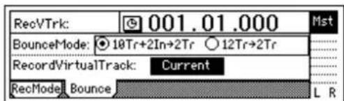
④ Specify that the currently-selected tracks will be used for recording.
Set "RecordVirtualTrack" to "Current."
⑤ Select the tracks that will be played and recorded. Press the [TRACK STATUS] keys to set the playback tracks (1–10) to PLAY (LED lit green), and the recording tracks (11, 12) to REC (LED lit red).
⑥ Adjust the pan of the playback tracks. Press the [PLAY] key to play back, and turn the [PAN] and [BALANCE] knobs to adjust the stereo positions of tracks 1–10. Set the channel 11/12 [BALANCE] knob to the center.
⑦ Adjust the playback and input levels. Use the [CHANNEL] faders to adjust the playback and input levels.
- Press the [METER/TRACK VIEW] key.
- Select the "button and press the [ENTER] key to open the dialog box. Select "PostFaderLev" so that you can view meters for the faders.
⑧ Adjust the recording level.
Use the [MASTER] fader to adjust the recording level. When you have finished making adjustments, press the [STOP] key.
⑨ Begin bounce-recording. Refer to steps ⑧–⑪ of "Combining twelve tracks of audio and overwrite-recording them on two tracks" (→p.64).
note After recording or track editing, you can execute Undo to return to the state prior to recording or track editing ( p.126).
2. Creating an original CD
2-1. Creating an audio CD
Using the optional CDRW-1 (sold separately) installed in the D1200, you can create an audio CD of a song that you recorded on the D1200.
note For details on installing the CDRW-1, refer to p.149.
In order for you to create an audio CD, the hard disk must have as much free space as occupied by the song you are creating (the total of two tracks). For example if you want to create an audio CD of a five-minute song, you will need as much free space as occupied by a ten-minute monaural recording.
Writing a song to an CD
① Select the song that you want to write.
② Listen to the mixed-down song. Use the faders and knobs to adjust the volume and pan etc. of the tracks, and play back to check the result.
note To enable recall of the registered scenes, turn the [SCENE] "ReadDel" tab page "SceneRead" setting "On."
③ Apply a final effect. (→p.43)
④ Bounce-record to two tracks. Mix your song down to two tracks as described in "1-1. Combining multiple tracks into two tracks" (→p.64).
Note If a song containing no silence at the beginning (i.e., at "zero" time) is written to CD, some sound at the beginning of the song may be skipped when the CD is played back. If this is the case, insert about 0.5 seconds of silence at the beginning of the mixdown audio data. (→p.58, 109: "InsertTrack")
⑤ Access the [CD] "Prepare" tab page.
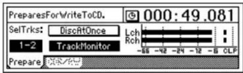
- T urn the "DiscAtOnce" button off.
- Set "SelTrks" to the two tracks where the final mix that you want to master is recorded.
- T urn "TrackMonitor" on, and press the [PLAY] key to hear the sound of the tracks you selected in "SelTrks." Watch the meters to see whether the level is too low or too high (clipping).
⑥ Insert a disc into the CDRW-1.
Use either a blank disc or a disc that has not yet been finalized.
⑦ Access the [CD] "CDR/RW" tab page.
Make sure that "CD-R/RW Information" indicates "BlankDisc" or "CD track number."
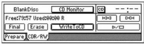
⑧ Execute writing.
- Select the "WriteToCD" button and press the [ENTER] key.
- Select the writing speed. For this example, select "8X" to select 8X speed writing.
note In order to use "8X" writing, the disc must both support 8X writing.
- The "Obey Copyright Rules" message will appear.
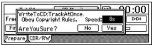
- Carefully read the owner's manual section "COPYRIGHT WARNING" (→p.1), and if you accept the terms, press the [YES/OK] key.
- An image file will be generated.
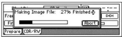
note If you select the "Abort" button and press the [ENTER] key, creation of the image file will be aborted.
- CD writing will begin. The data will start being written to the CD.
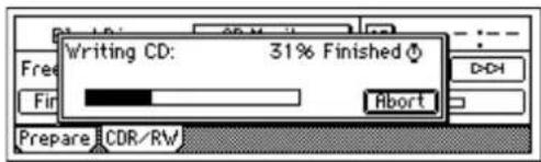
While the data is being written, you can select the "Abort" button and press the [ENTER] key to abort writing to the CD. In the case of a CD-R, the disc will become unusable. If you are using a CD-RW disc, perform the procedure described in "3. Erasing a CD-RW disc" (→p.76) before you use it.
- When writing ends, the display will indicate "Completed." If you want to create another CD with the
same content, press the [YES/OK] key. To proceed to the next step, press the [NO/CANCEL] key.
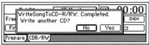
⑨ If you want to write another song to the disc, repeat steps ①-⑧. Subsequently written songs will be added after the last song on the CD-R/RW.
⑩ Finalize the disc. If you want to be able to play the CD-R/RW in an audio CD player, select the "Final" button when you are finished, and press the [ENTER] key to finalize the disc. A message will ask you to confirm execution. If you are sure you want to execute, press the [YES/OK] key.
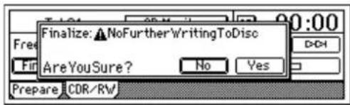
Note Once a disc has been finalized, no further songs can be written to it. Finalize a disc only after you have written all the songs you want to write to that disc.
- When finalization has been completed, the tray of the CDRW-1 will open.
⑪ Play the disc in an audio CD player to verify that the disc was written correctly. Play it back on a CD player to verify that the audio CD was created correctly.
note Since audio CD players are sometimes unable to play CD-RW discs, we recommend that you use CD-R media.
Making an audio CD from a live recording
When you want to make an audio CD from material that was recorded as a single song, such as a live recording or a long song, you can write it to the CD using Disc At Once. Marks registered within the song can be used to indicate the divisions between CD tracks, allowing you to create a live CD with no gaps between tracks. Also, an audio CD created using Disc At Once can be used as a master CD for pressing.
When you use "DiscAtOnce" to write a disc, it will be finalized automatically. No additional data can be written to that disc.
① Make preparations as described in steps ①–③ of "Writing a song to an CD."
② Register a mark in each location at which you want to divide the CD into tracks. (→p.33)
③ Access the [CD] "Prepare" tab page.
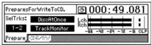
- Turn the "DiscAtOnce" button on.
- Set "SelTrks" to the two tracks that you want to master.
- T urn "TrackMonitor" on, and press the [PLAY] key to hear the sound of the tracks you selected in "SelTrks." Watch the meters to see whether the level is too low or too high (clipping).
④ Insert a disc into the CDRW-1.
You must use a blank disc.
⑤ Access the [CD] "CDR/RW" tab page.
Make sure that "CD-R/RW Information" indicates "BlankDisc."
⑥ Write the data.
- Select the "WriteToCD" button and press the [ENTER] key.
- Select the writing speed.
note When you write using "DiscAtOnce," finalization will be performed automatically.
3. Recording to a master tape
① Check your completed song.
Use the faders and knobs to adjust the volume and pan of the tracks, and play back to check the result.
② Connect your external recording device.
Connect your MD or DAT etc. to the [S/P DIF OUT] jack or the [MASTER OUT] jacks.
③ Record on the external device.
• Play back the D1200 song, and adjust the level on your external recorder.
• Start recording on your external recorder, and play back the D1200 song.
By using the Program Play function you can successively play back songs in the desired order (→p.56).
4. Using sub inputs
You can use any of the analog inputs ([INPUT1/GUITAR IN]-[INPUT 4]) as sub inputs to send audio directly to the master bus.
- Y ou can play back a completed song in synchronization with an external sequencer that drives a sound module, and send the output of your sound module to the sub input.
- You can apply an external effect to the audio signal sent from the [AUX OUT] jack, and use sub input as the return from the external effect.
① Connect your sound module etc. to the analog inputs. You can use [INPUT 1/GUITAR IN]–[INPUT 4].
② Patch the inputs to the sub in.
- Access the [INPUT/OUTPUT/SOLO] "Ch1-6" or "Ch7-12" tab page.
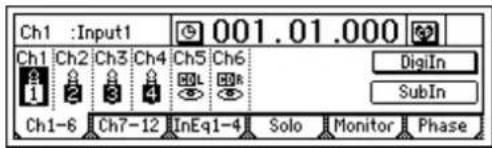
- Select the "SubIn" button and press the [ENTER] key to access the "Sub input setting" screen. (→p.98)
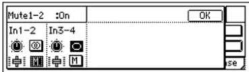
- T urn the "M (Mute)" button "Off" for the inputs to which your sound module (or effect processor) is connected.
- Select the "Fader" icon, and turn the [VALUE] dial to raise the value so that the audio signal will be input.
- If your input source is monaural, select the "Stereo/Mono" button and press the [ENTER] key to select "Mono," so that the audio signal will be sent to both L and R buses.
Data
Whenever you switch songs or turn off the power, the D1200's Auto Save function will automatically save (to the hard disk) the songs or parameters that you recorded or edited.
This means that you do not need to perform any particular operations to save your data.

You do need to save the effect settings if you have edited effect programs.
The data saving operations explained in this section are used when you have created important data on the D1200 that you want to save on a CD-R/RW or your computer, or when you want to delete data from the hard disk to obtain more free space.
If you want to save data to your computer, you must first save the data on the USB drive of the internal hard disk, and then save that data on your computer.
You can save the following data.
- Song data
• E f fect user data
• W AV files: audio files in WAV format

Creating an audio CD will not save the parameter settings that were used to create the songs. To save this data, you must back it up.
Data saving procedure, and the types of data that can be saved
| Data save method | File type | Save data to | |
| →CD-R/RW | →USB drive | ||
| Backup1Song | 1 song + All user effects | ○ | ○ |
| BackupAllSongs | All songs + All user effects | ○ | × |
| BackupUserData | All user effects | ○ | ○ |
| Insert, Master, or Final user effect | × | ○ | |
| Export | WAV format file | ○ | ○ |
Filename extension of the file saved on the USB drive
| Data save method | Extension file type | |
| Backup1Song | 1 song | .DBK |
| BackupUserData | All user effects | .DFX |
| Insert User Data [Ins001-Ins128] | .DFI | |
| Master User Data [Ms:001-Mst032] | .DFM | |
| Final User Data [Fin033-Fin054] | .DFF | |
| Export | WAV format file | .WAV |
1. Backing up and restoring song data
1-1. Backing up song data
You can back up song data in two ways.
Backup1Song: Back up the selected song.
BackupAllSongs: Back up all songs (only to CD-R/RW).
• E f fect user data will also be saved.
- A backed-up song cannot be played back directly. In order to play the song, you must Restore it.
Backing up to CD-R/RW
Here's how to back up all songs to one or more CD-R/RW discs.

No further data can be stored on a CD-R/RW disc that has been used for backup.

CD-R/RW discs created by the backup operation are not in ISO9660 format. This data cannot be read by a computer, or played back by a CD player.
① Insert a CD-R/RW disc into the CD-R/RW drive. You must use a blank (empty) disc. If you want to erase existing data from a CD-RW disc to make it blank, follow the procedure described in "Erase a CD-RW disc" (→p.106).

② Select "BackupAllSongs."
In the [SYSTEM/USB] "B-U/Rst" tab page, select "B-U/RstType," and turn the [VALUE] dial to select "BackupAllSongs." You can also select the "button and press the [ENTER] key to view and choose "Select Backup/Restore Type."
③ Verify the songs that will be backed up.
Make sure that "Source" is set to "ALL."
④ Select the backup-destination drive.
Select the "Drive" button and press the [ENTER] key to open the dialog box. Select "C:CD" and press the [YES/OK] key.
![S:HDD38.8G C:CD [B] U:USB DOS OK Cancel](/content/2026/05/820878/images/5db3f73be2c4cf6af4f200fa51e55bf9d66edb228699ff47111352c1ba4f6f39.jpg)
⑤ Check the backup-destination drive and the drive information.
Make sure that "Destination" is set to C:CD. The display will indicate the number of CD-R/RW discs required.
You will need to provide the required number of discs of that capacity.

When using multiple discs, we recommend that you number them beforehand.
⑥ Back up the data.
Select the "Exec." button and press the [ENTER] key to access the confirmation screen. Here you can specify the writing speed.
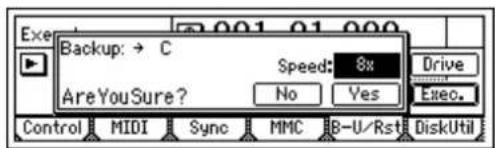
- Press the [YES/OK] key to begin the backup. User effect data will also be backed up at this time.
- If you need to use multiple discs, a dialog box will appear when one disc is full, asking you to insert the next disc. Insert the next disc and press the [YES/OK] key.
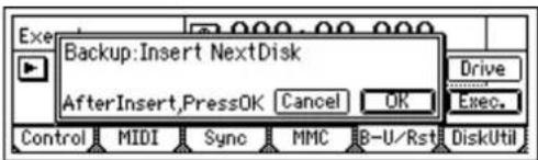
- When the backup is complete, the display will indicate "Completed." Press the [YES/OK] key.
note After data is backed up to CD-R/RW, the automatic compare function will compare the disc to ensure that a faulty backup CD is not created.
Note If you press the "Cancel" button while data is being written to CD-R, writing will be aborted and the disc will be incomplete. In the case of a CD-RW, the data that had been written up to that point will be erased.
Backing up to the internal USB drive
Here's how to back up the selected song to the internal USB drive.
① Select the song that you want to back up. (→p.31: "1-3. Selecting different songs")
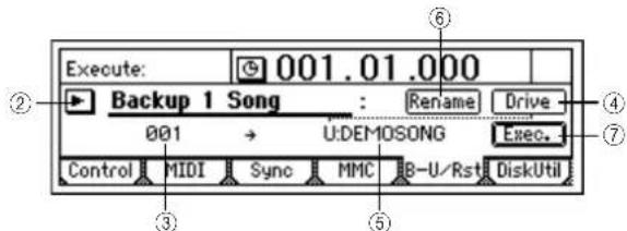
② Select "Backup 1 Song."
In the [SYSTEM/USB] "B-U/Rst" tab page, select "B-U/RstType" and turn the [VALUE] dial to select "Backup 1 Song." You can also press the "button and press the [ENTER] key to view and choose "Select Backup/Restore Type."
③ Verify the song for backup.
Make sure that the song you want to back up is selected in "Source."
④ Select the backup-destination drive.
Select the "Drive" button and press the [ENTER] key to open the dialog box.
Select U:USB DOS, and press the [YES/OK] key.
⑤ Check the backup-destination drive and file name. The name of the song being backed up will be the file name. Make sure that "Destination" is set to "U:(song name)."
⑥ Edit the file name.
If you want to edit the file name, select the "Rename" button and press the [ENTER] key. Edit the file name in the "RenameFile" dialog box. (→p.31)
note If an identically-named file already exists on the USB drive, you will be unable to save. You will need to re-name the file.
⑦ Back up the data.
- Select the "Exec." button and press the [ENTER] key.
A screen will ask you for confirmation.
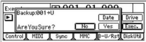
- Y ou can specify the date and time that the file was created. Select the "Date" button and press the [ENTER] key to open the dialog box, use the cursor to select the date or time that you want to set, and use the [VALUE] dial to specify the date and time.
- When you press the [YES/OK] key, backup will begin. Effect user data will also be backed up at this time.
Note Effect user data will be saved using the same file name that you specified in steps ⑥ and ⑦ followed by the suffix .DFX. This data cannot be saved if an identically-named file already exists on the USB drive. You will need to rename the file.
1-2. Restoring song data
Here's how you can restore previously backed up song data, so that it can be played.
Restoring
① If you are restoring data from a CD-R/RW disc, insert the disc into the CD-R/RW drive.
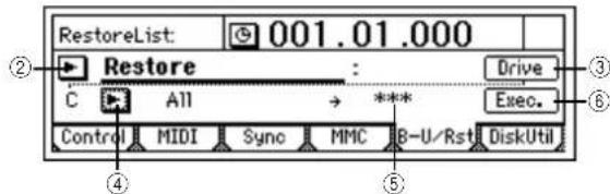
② Select "Restore."
In the [SYSTEM/USB] "B-U/Rst" tab page, select "B-U/RstType" and turn the [VALUE] dial to select "Restore."
You can also select the "button" and press the [ENTER] key to display "Select Backup/Restore Type" and make your selection.
③ Select the restore-source drive.
Select the "Drive" button and press the [ENTER] key to open the dialog box.
Select either C:CD[B] or U:USB DOS, and press the [YES/OK] key.
④ Select the restore-source song.
Select the "button and press the [ENTER] key. In the "Select RestoreSong" dialog box, select the desired song.
When restoring from a CD-R/RW
Select the song to be restored from the file list.
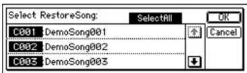
If you want to restore all songs, turn on the "SelectAll" button.
Select the song, and press the [YES/OK] key.
When restoring from the USB drive
Select the song to be restored from the file list.
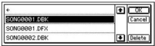
It is not possible to restore all songs at once.
Select the song, and press the [YES/OK] key.
⑤ If you are restoring a single song, select the restore-destination song.
Move the cursor to "Destination," and use the [VALUE] dial to select the restore-destination song number.
⑥ Restore the data.
Select the "Exec." button and press the [ENTER] key. The display will ask "AreYouSure?." Select the "Yes" button and press the [ENTER] key to execute the operation.
If you are restoring a backup that extended across more than one disc, you will be asked to insert the next disc when one disc has been read. Insert the next disc, and press the [YES/OK] key. Insert the discs in the order in which they were backed up.
At the end of the process, you can select whether to restore effect user data. If you do so, the effect user data currently on the hard disk will be overwritten.
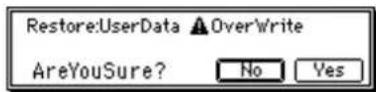
Press the [YES/OK] key.
The effect user data will be restored, overwriting the effect user data that is on the hard disk.
If you press the [NO/CANCEL] key, the effect user data will not be restored.
Note: If you are restoring from a USB drive, the effect user data will not be restored if there is no effect user data file of the same name as the song being restored.
⑦ When the restore operation has been completed, the display will indicate "Completed." Press the [YES/OK] key.
2. Backing up and restoring effect user data
2-1. Backing up user effect data
You can backup effect user data in the following ways.
- Backup all effect user data.
- Backup effect user data individually (only to the USB drive)
Note You can also save all effect user data when you back up song data.
When you restore this data, the effect user data currently on the hard disk will be overwritten.
Backing up to CD-R/RW
Here's how to back up all effect user data to a CD-R/RW disc.
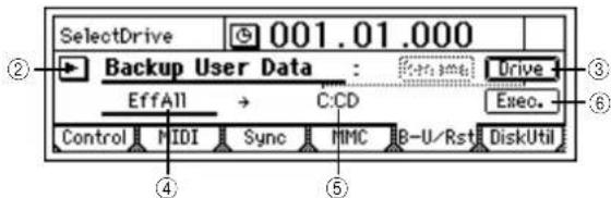
① Insert a CD-R/RW disc into the CD-R/RW drive.
② Select "BackupUserData."
In the [SYSTEM/USB] "B-U/Rst" tab page, select "B-U/RstType" and turn the [VALUE] dial to select "BackupUser Data." You can also select the "button and press the [ENTER] key to display "Select Backup/Restore Type" and make your selection.
③ Select "C:CD" as the backup-destination drive.
Select the "Drive" button, and press the [ENTER] key to open the dialog box.
Select "C:CD" and press the [YES/OK] key.
④ Make sure that "Source" is set to "EffAll."
⑤ Make sure that "Destination" is set to "C:CD."
⑥ Back up the data.
Select the "Exec." button and press the [ENTER] key. A screen will ask you for confirmation. Here you can specify the writing speed.
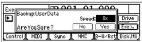
- P r ess the [YES/OK] key to begin the backup.
- When the backup has been completed, the display will indicate "Completed." Press the [YES/OK] key.
Note After data is backed up to CD-R/RW, the automatic compare function will compare the disc to ensure that a faulty backup CD is not created.
Note If you press the "Cancel" button while data is being written to CD-R, writing will be aborted and the disc will be incomplete. In the case of a CD-RW, the data that had been written up to that point will be erased.
Backing up to the internal USB drive
Here's how to back up insert effect "U055" from the user area to the internal USB drive.
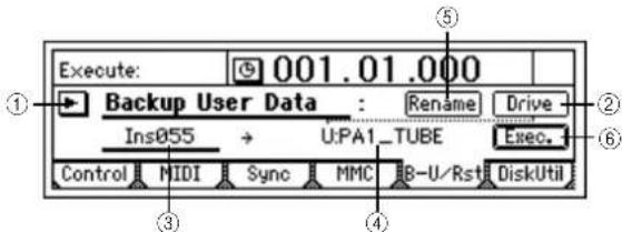
① Select "BackupUserData."
In the [SYSTEM/USB] "B-U/Rst" tab page, select "B-U/RstType," and turn the [VALUE] dial to select "BackupUserData." You can also select the "button and press the [ENTER] key to display "Select Backup/Restore Type" and make your selection.
② Select "U:USB DOS" as the backup-destination drive. Select the "Drive" button and press the [ENTER] key to open the dialog box. Select "U:USB DOS" and press the [YES/OK] key.
③ Select the effect that you want to back up. Move the cursor to "Source," and use the [VALUE] dial to select "Ins055."
④ Verify the backup-destination drive and file name. The name of the effect being backed up will be the file name. Make sure that "Destination" is set to "U:(effect name)."
⑤ Edit the file name. If you want to edit the file name, select the "Rename" button and press the [ENTER] key. Edit the file name in the "RenameFile" dialog box. (→p.31)
note If an identically-named file already exists on the USB drive, you will be unable to save. You will need to re-name the file.
Note If you select all effects "EffAll," the name of the currently selected song will be used as the file name of the effect user data file.
⑥ Execute the backup.
- Select the "Exec." button and press the [ENTER] key. A screen will ask you for confirmation.
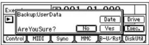
- You can specify the date and time that the file was created. Select the "Date" button and press the [ENTER] key to open the dialog box, use the cursor to select the date or time that you want to set, and use the [VALUE] dial to specify the date and time.
- When you press the [YES/OK] key, backup will begin.
2-2. Restoring effect user data
Restoring
① If you are restoring from a CD-R/RW disc, insert the disc in the CD-R/RW drive.
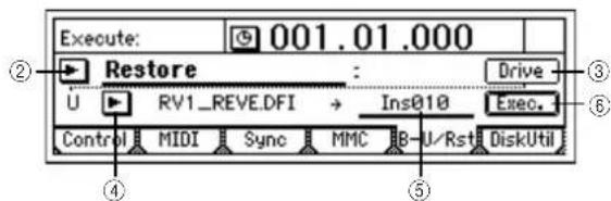
② Select "Restore."
In the [SYSTEM/USB] "B-U/Rst" tab page, select "B-U/RstType" and turn the [VALUE] dial to select "Restore." You can also select the "button" and press the [ENTER] key to display "Select Backup/Restore Type" and make your selection.
③ Select the restore-source drive.
Select the "Drive" button and press the [ENTER] key to open the dialog box. Select either C:CD[B] or U:USB DOS, and press the [YES/OK] key.
④ If you are restoring from the USB drive, select the effect user data that you want to restore.
- Select the "button and press the [ENTER] key.
- From the "BackUpFileList," select the effect that you want to restore. For details on the types of file, refer to p.68. Then press the [YES/OK] key.
⑤ Verify the restore-destination.
- If you are restoring all user effect data, this will be displayed as “***”.
- If you are restoring individual effect user data, select the restore-destination effect number. Move the cursor to "Destination," and use the [VALUE] dial to select the restore-destination effect number.
⑥ Restore the user effect data.
- Select the "Exec." button and press the [ENTER] key. The display will ask "AreYouSure?." Press the [ENTER] key to execute the operation.
⑦ When execution is completed, the display will indicate "Completed." Press the [YES/OK] key.
3. Reading and writing WAV files
Importing (loading) a WAV file: A WAV-format audio file saved on CD-ROM/R/RW or the USB drive can be pasted into a track of a D1200 song.
note You can use Undo to return to the prior state.
Exporting (writing) a WAV file: Audio track data copied to the D1200's clipboard can be exported (written) as a WAV-format to a CD-R/RW disc or the USB drive.
3-1. Importing (reading) a WAV file
You can import WAV files of the following formats.
Sampling frequency: 44.1 kHz Bit depth: 8-bit, 16-bit, 24-bit Channels: 1 (monaural), 2 (stereo)
In order to import a WAV file from your computer, you must connect a USB cable between the D1200 and your computer, and copy the WAV file onto the internal USB drive of the D1200.
Importing a WAV file into the beginning of a track
Here's how to import a monaural WAV file named "D1200_MN.WAV from a CD, and paste it into the beginning of track 1.
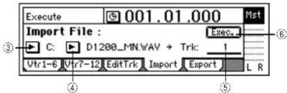
① Insert the CD-R/RW disc containing the WAV file into the CD-R/RW drive.
② Select the Import command.
- Access the [TRACK] "Import" tab page.
③ Select the import-source drive.
- Select the "DriveList" button and press the [ENTER] key to open the dialog box.
- Select "C:CD" and press the [YES/OK] key.
④ Select the WAV file that you want to import.
- Select the "WavFileList" button and press the [ENTER] key to open the dialog box.
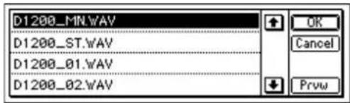
- You can use the "Prvw" button to hear approximately two seconds of the beginning of the selected WAV file.
- Select "D1200_MN.WAV" and press the [YES/OK] key.
⑤ Select the import-destination track number.
- Set "DestTrack" to track "1."
⑥ Import the file.
- Select the "Exec." button and press the [ENTER] key.
- The display will ask "AreYouSure?" Press the [YES/OK] key to execute the operation.
- When the operation is completed, the display will indicate "Completed." Press the [YES/OK] key.
The longer the file being imported, the longer this operation will take until the "Completed" display appears.
⑦ Move the time location to the beginning of the song, and check that the file was imported correctly.
Importing a WAV file into the middle of a track
Here's how to import a stereo WAV file named "D1200_ST.WAV from the USB drive, and paste it in to tracks 1 and 2 at the TO location (the location registered in the [TO/LOC3] key).
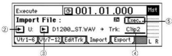
① Select the Import command. Access the [TRACK] "Import" tab page.
② Select the import-source drive.
- Select the "DriveList" button and press the [ENTER] key to open the dialog box.
- Select "U:USB DOS" and press the [YES/OK] key.
③ Select the WAV file that you want to import.
- Select the "WavFileList" button and press the [ENTER] key to open the dialog box.
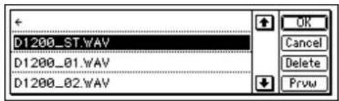
Select "D1200_ST.WAV" and press the [YES/OK] key.
④ Select the clipboard as the import-destination track. Set "DestTrack" to "Clip2."
note The number indicates the number of tracks in the clipboard. In the case of a monaural file, this will be "Clip1."
⑤ Import the data to the clipboard.
- Select the "Exec." button and press the [ENTER] key.
- The display will ask "AreYouSure?" Press the [YES/OK] key to execute the operation.
- When the operation is completed, the display will indicate "Completed." Press the [YES/OK] key.
The longer the file being imported, the longer it will take for this operation to be finished and the "Completed" display to appear.
⑥ Register the TO location.
(→p.33: "Registering a location to one of the Locate keys")
⑦ Select the Copy command.
In the [TRACK] "EditTrk" tab page, set "EditType" to "CopyTrack."
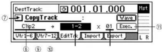
⑧ Select the clipboard as the copy-source track. Set "SourceTrack" to "Clip2."
⑨ Select the tracks 1 and 2 as the copy-destination tracks. Set "DestTrack" to "1-2."
⑩ Specify the number of times that the data will be copied. Set "Times" to "1."
⑪ Copy the clipboard data to the track.
- Select the "Exec." button and press the [ENTER] key.
- The display will ask "AreYouSure?" To execute, press the [YES/OK] key.
- When the copy operation has been completed, the display will indicate "Completed." Press the [YES/OK] key.
note The data will be overwritten onto the copy-destination track.
⑫ Press the [TO/LOC3] key, play back from the TO location, and listen to the playback to verify that the data was imported correctly.
3-2. Exporting (writing) a WAV file
You can export (write) audio data as a WAV file in the following formats.
Sampling frequency: 44.1 kHz
Bit depth: 16-bit, 24-bit
Channels: 1 (monaural), 2 (stereo)
note When exporting to a CD-R/RW disc, you can export additional files to the same disc at a later time.
note Exported WAV file data can be read by the D1200 or by a computer even if the disc has not been finalized.
note WAV files exported to a CD-R/RW are in ISO9660 level 1 format.
note Files exported to the internal USB drive can be saved to your computer.
Exporting a WAV file
Here's how you can copy the IN-OUT region of tracks 1 and 2 in a 16-bit song to the clipboard, and export this audio data to a stereo WAV file named "D1200_ST.WAV.
① Select a 16-bit song that you created. (→p.31: "1-3. Selecting different songs")
② Register the IN and OUT locations. ( p.33, 118)
③ Copy the track data to the clipboard.
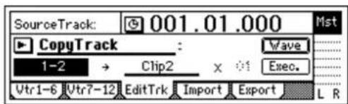
- In the [TRACK] "EditTrk" tab page, set "EditType" to "CopyTrack."
- Set "SourceTrack" to "1–2."
- Set "DestTrack" to "Clip2."
note The number indicates the number of tracks in the clipboard.
- Select the "Exec." button and press the [ENTER] key.
- The display will ask "AreYouSure?" Press the [YES/OK] key to execute.
- When the operation has been executed, the display will indicate "Completed." Press the [YES/OK] key.
④ Select the Export function.
Access the [TRACK] "Export" tab page.
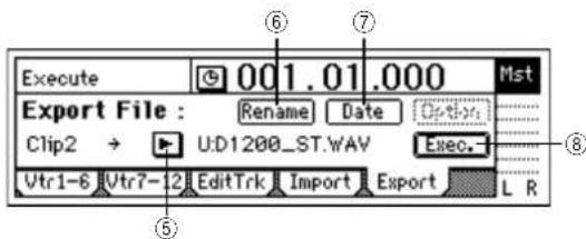
⑤ Select the export-destination drive.
For this example, select the USB drive "U:USB DOS."
⑥ Edit the name of the WAV file.
If you want to change the name of the file, select the "Rename" button and press the [ENTER] key. Edit the name in the "RenameFile" dialog box. (→p.31)
note When you export a stereo WAV file, the 7th and 8th characters of the file name will automatically be set to "ST." For a monaural file, this will be "MN."
note The file cannot be saved if an identically-named file already exists on the USB drive.
⑦ Specify the date and time of the WAV file.
- Press the "Date" button to access the dialog box, move the cursor to the date or time you want to change, and use the [VALUE] dial to set the data and/or time.
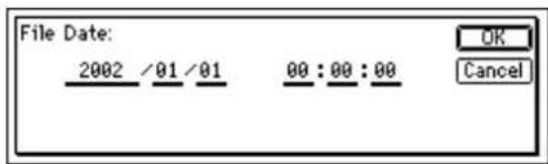
⑧ Export the clipboard data.
- Select the "Exec." button and press the [ENTER] key.
- The display will ask "AreYouSure?." Press the [YES/OK] key to execute.
- When the operation has been executed, the display will indicate "Completed." Press the [YES/OK] key.
Exporting multiple WAV files
When you export four or more tracks at once, each track will be saved as a monaural file.
Here's how to copy the IN-OUT region of tracks 1–6 of the 24-bit song 003 to the clipboard, and export them to a CD-R/RW disc as six monaural WAV files named "D1200_1.WAV"- "D1200_6.WAV."
① Insert a CD-R/RW disc into the CD-R/RW drive. When exporting WAV files to the CD-R/RW drive, you can use either a blank CD-R/RW disc or an unfinalized ISO9660 format CD-R/RW disc.
② Select a 24-bit song that you created. (→p.31: "1-3. Selecting different songs")
③ Register the IN and OUT locations. (→p.33)
④ Copy the track data to the clipboard.
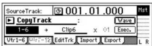
- In the [TRACK] "EditTrk" tab page, set "EditType" to "CopyTrack."
- Set "SourceTrack" to "1–6."
- Set "DestTrack" to "Clip6."
note The number indicates the number of tracks in the clipboard.
- Select the "Exec." button and press the [ENTER] key.
- The display will ask "AreYouSure?" Press the [YES/OK] key to execute.
- When the operation has been executed, the display will indicate "Completed." Press the [YES/OK] key.
⑤ Select the Export function.
Access the [TRACK] "Export" tab page.
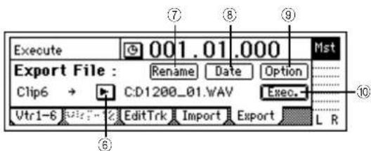
⑥ Select the export-destination drive.
- For this example, select "C:CD."
⑦ Edit the name of the WAV files.
- If you want to change the name of the file, select the "Rename" button and press the [ENTER] key. Edit the name in the "RenameFile" dialog box. (→p.31: "1-2. Editing the name of a song")
- When you export six tracks simultaneously, the 7th and 8th characters of the file name will automatically be set to a number 01–06. You cannot change this.
note The file cannot be saved if an identically-named file already exists on the USB drive.
⑧ Specify the date and time of the WAV files.
- Press the "Date" button to access the dialog box, move the cursor to the date or time you want to change, and use the [VALUE] dial to set the data and/or time.
⑨ Make export settings.
- Press the "Option" button to open the dialog box, and specify the CD writing speed. (→p.115)
- If you turn the "Finalize" button on, it will not be possible to write any additional data to that disc. ( p.94)
⑩ Export the files from the clipboard.
- Select the "Exec." button and press the [ENTER] key. If you are exporting a 24-bit song as a 16-bit WAV file, make "bit" and "Dither" settings. (→p.115)
- The display will ask "AreYouSure?." Press the [YES/OK] key to execute.
- When the operation has been executed, the display will indicate "Completed." Press the [YES/OK] key.
4. Drive and data compatibility between models of the Digital Recording Studio series
This section discusses data compatibility between the Digital Recording Studio series models D12, D16 (version 2.0 or later), D1600, and D1200.
note Be aware of the following points regarding effect user data.
The algorithms of the D1200 differ from the algorithms of the D12/16/1600.
48: PA1: Pre Amp Simulator
49: EB1: Bass Multi 1
52: MS1: Mic Multi
If effect user data using these algorithms is restored to the D12/16/1600, it will not produce the same sound. Similarly, effect user data created on the D12/16/1600 using these three algorithms will not sound the same if it is restored to the D1200.
If an insert effect preset is used in a scene, the settings will be different when that scene is played back. You will need to edit the insert effect settings.
Using D12 data on the D1200
A CD-R/RW disc containing D12 data can be used in the same way as D1200 data.
Using D1200 data on the D12
A CD-R/RW disc containing D1200 data can be used in the same way as D12 data.
Using D16 or D1600 data on the D1200
ACD-R/RW disc containing D16 or D1600 data can be used in the same way as D1200 data. However in the case of song data or effect user data, the drive list will indicate "D16[B]," and the data for tracks 13–16 cannot be restored.
Using D1200 data on the D16 or D1600
ACD-R/RW disc containing D1200 data can be used in the same way as D16 or D1600 data. However in the case of song data or effect user data, the drive list will indicate "D12[B]."
In order to use D1200 data on the D16, you must update the D16 system to version 2 or later.
Drive
The hard disk of the D1200 is divided into a "song drive" that is used for recording and playing songs, and a "USB drive" that is used to exchange data with a computer.
Note Of the total capacity of the hard disk, the size of the USB drive is fixed at 2 GB, and the remainder is the capacity of the song drive.
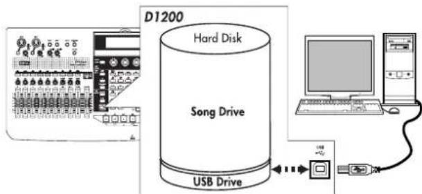
flowchart
graph TD
    A["D1200 Audio System"] --> B["Hard Disk"]
    B --> C["Song Drive"]
    C --> D["USB Drive"]
    D --> E["Computer"]
Perform the procedures described below if you want to erase data from a drive or CD-RW, or if an error display appears.
1. Checking the hard disk
This operation checks the song drive of the hard disk for errors, and repairs errors that are found. Execute this operation if the "DiskError" error message appears frequently. If no major errors are detected on the drive, you can continue to use the song data.
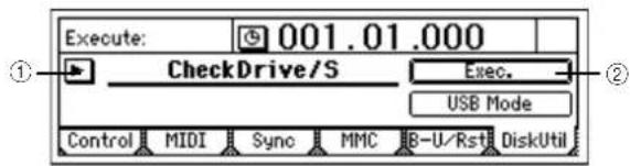
① Select "CheckDrive/S."
- Select "SelOperation," and use the [VALUE] dial to select "CheckDrive/S."
② Execute the check.
- Select the "Exec." button, and press the [ENTER] key to open the dialog box.
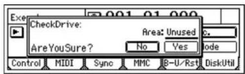
- Specify the area that you want to check. For this example, select "Unused."
- Press the [YES/OK] key to begin the check.
- When checking is finished, the display will indicate "Completed." Press the [YES/OK] key.
2. Formatting the hard disk
Perform this procedure if you want to erase data from the entire song drive or USB drive, or if the "Disk Error" display appears frequently, or if checking the hard disk does not improve the situation. You can format the song drive and USB drive together in a single operation, or format them separately.
When you execute the Format operation, all data on the disk will be erased. Be sure to check the contents of the disk before you format it.
If a power failure or similar accident occurs during the formatting process, it is possible that the D1200 will no longer operate correctly. If this occurs, please contact your Korg distributor.
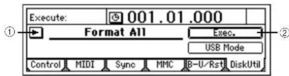
① Select the type of formatting.
- Access the [SYSTEM/USB] "DiskUtil" tab page, choose "SelOperation," and turn the [VALUE] dial to select the type of formatting. Format ALL: Format the entire hard disk Format/S: Format the song drive Format/U: Format the USB drive
② Execute formatting.
- Select the "Exec." button and press the [ENTER] key to open the dialog box.
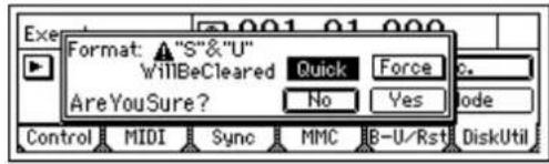
- Use "Quick" to select how the disk will be formatted. If you turn this "On," only the system area will be initialized, and the operation will not require very much time. Select "Off" if "DiskError" is displayed frequently, or if you experience problems such as failure to recognize the disk drive even after it is formatted with "Quick" turned "On."
- If you turn the "Force" button "On," formatting will be executed even if the drive contains a protected song. If this is off when you execute formatting, and the disk contains a protected song, a message of "SongProtect" will be displayed, and the operation will be aborted.
- Press the [YES/OK] key to begin the formatting operation.
- When formatting is finished, the display will indicate "Completed." Press the [YES/OK] key.
Executing the format operation with "Quick" turned "Off" will require a substantial length of time. 40 GB: On → approximately 7 seconds; Off → approximately 8 hours
If you continue using the D1200 for an extended period, the bottom of the unit may become hot, but this is not a problem for operation. If you are touching the bottom of the D1200 and find that it has become uncomfortably hot, place the unit on a tabletop.
3. Erasing a CD-RW disc
This operation erases the data that was written on a CD-RW disc.
Erasing a disc lets you use the entire capacity of the disc, just as when it was unused (blank).
When you execute "EraseCD-RW," all data will be erased from the CD-RW disc.
"EraseCD-RW" cannot be executed on a drive other than a CD-RW drive.
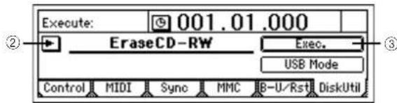
① Insert the CD-RW disc into the CD-R/RW drive.
② Select "EraseCD-RW."
- Select "SelOperation," and use the [VALUE] dial to select "EraseCD-RW."
③ Execute the erase operation.
- Select the "Exec." button and press the [ENTER] key to open the dialog box.
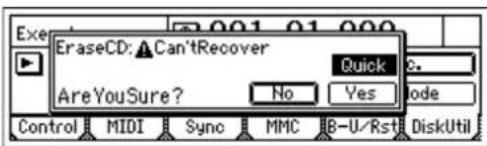
- Use "Quick" to select how the disc will be erased. If you turn this "On," the entire CD-RW disc will be erased at high speed. Normally you will select this. If you turn this "Off," the entire CD-RW disc will be erased completely. Use this if you experience a problem such as if the disc fails to be recognized even after it has been erased with "Quick" turned On.
- Press the [YES/OK] key to begin the erasing operation.
- When formatting is finished, the display will indicate "Completed." Press the [YES/OK] key.
note CD-RW discs can also be erased in the [CD] "CDR/RW" tab page.
4. Drive capacity
This section explains how you can make the best use of the D1200's song drive capacity. For explanatory purposes, we will assume that you have recorded a song with the following structure.
| Intro | A B So | oBreak | Ending |
Note The Optimize Track operation described here does not need to be performed often. It is sufficient to perform this operation when the "DiskBusy" indication appears, or when you want to recover disk drive capacity after completing a song.
Example 1: You began recording on track 1 from the beginning of the song, and only played during the Intro, Break, and Ending on the first take.
| Silence | Intro | Break | Ending | Silence |
In this case, silence (actually, noise-level sound) will have been recorded in the A, B, and Solo sections of track 1, unnecessarily using up valuable drive space.
To keep the audio data only for the Intro, Break, and Ending that you are actually using
Execute the Optimize Track operation on track 1, from the beginning of the song to the end of the song. Set the Optimize Track "Mode" parameter to "Erase Silence," and execute. This will cause audio data to be preserved only for the actually-used regions, so that only the intro, break, and ending will occupy drive space.
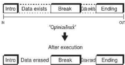
flowchart
graph TD
    A["Intro"] --> B["Data exists"]
    B --> C["Break"]
    C --> D["Data exists"]
    D --> E["Ending"]
    F["OptimizeTrack"] --> G["After execution"]
    G --> H["Intro"]
    H --> I["Data erased"]
    I --> J["Break"]
    J --> K["Data erased"]
    K --> L["Ending"]
    style A fill:#f9f,stroke:#333
    style B fill:#ccf,stroke:#333
    style C fill:#cfc,stroke:#333
    style D fill:#fcc,stroke:#333
    style E fill:#cff,stroke:#333
    style F fill:#ffc,stroke:#333
    style G fill:#cfc,stroke:#333
    style H fill:#fcc,stroke:#333
    style I fill:#cfc,stroke:#333
    style J fill:#cfc,stroke:#333
    style K fill:#cfc,stroke:#333
    style L fill:#fcc,stroke:#333
Example 2: You began recording on track 1 from the beginning of the song, and played the Intro, A, B, and Break during the first take, and then recorded a second take to overwrite A' and B'.
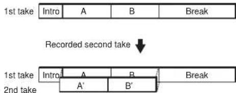
flowchart
graph TD
    A["1st take"] --> B["Intro"]
    B --> C["A"]
    C --> D["B"]
    D --> E["Break"]
    F["1st take"] --> G["Intro"]
    G --> H["A'"]
    H --> I["B'"]
    I --> J["Break"]
    K["Recorded second take"] --> L["↓"]
    style A fill:#f9f,stroke:#333
    style F fill:#f9f,stroke:#333
    style K fill:#f9f,stroke:#333
In this case, A and B of the first take remain "beneath" A' and B' of track 1, in order to preserve the data for Undo and also because they are a continuous piece of audio data with the Intro and Break. This means that Intro, A+A', B+B', and Break are occupying disk space.
To erase A and B that remain from the first take, and recover disk space
Execute the Optimize Track command on track 1 from the beginning to the end of the song. When this is executed, only the audio data of the 1st take Intro, 2nd take A', 2nd take B', and 1st take Break will be kept. This means that the 1st take A and 1st take B data will no longer occupy disk space.
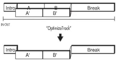
flowchart
graph TD
    A["Intro"] --> B["A"]
    B --> C["B"]
    C --> D["Break"]
    style A fill:#f9f,stroke:#333
    style B fill:#f9f,stroke:#333
    style C fill:#f9f,stroke:#333
    style D fill:#f9f,stroke:#333
    note right of D "OptimizeTrack"
Example 3: You recorded A and B on track 1 as the first take. As the second take, you overwrite-recorded the Intro, A', B', and Break.
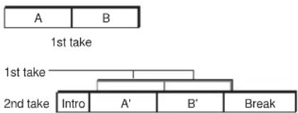
flowchart
graph TD
    A["A"] --> B["B"]
    style A fill:#f9f,stroke:#333
    style B fill:#ccf,stroke:#333
    note1["1st take"] --> A
    note2["1st take"] --> B
    note3["2nd take"] --> Intro["Intro"]
    note3 --> A'A'
    note3 --> B'B'
    note4["Break"] --> B'
In this case, the first take A and B remain "beneath" A' and B', but since the audio data of take 1 is not used at all once you finished recording take 2, there is no need to execute the optimize command.
Deleting the Undo data
Even if you use the drive space efficiently as described above (examples 1, 2, 3), the old data will be kept on the drive for use by the Undo function.
If you want to delete this Undo data, you can restart the D1200. When the D1200 is restarted, all Undo data will be deleted, and the unused drive space will be recovered.
Sharing event data
If you use the Copy Track operation to copy track data to another track (e.g., virtual track) or another song, this audio data will be shared, so that the drive capacity will not decrease. However if you execute the Optimize Track operation on the copy-destination or copy-source track, new audio data will be created, and this will mean that a greater amount of drive capacity will be used than before the operation was executed.
In the case of example 2, if you copy the first take to another track before you record the second time, executing the Optimize Track operation will not delete the "A" and "B" regions of the first take, and audio data for the "Intro" and "Break" regions will be newly created, meaning that a greater amount of drive capacity will be used.
USB
What is USB?
USB stands for Universal Serial Bus, and is an interface for transferring data between a computer and peripheral devices.
USB peripheral devices such as hard disks or CD-R/RW drives cannot be connected to the D1200.
The D1200 has a [USB] connector which you can connect directly to your computer, and save data to your computer from the USB drive area of the D1200's internal hard disk. Using the USB drive, the following types of data can be saved to your computer or loaded from your computer.
Song data
This is data for each track, as well as data such as pan and effect settings. Since this data is in the D1200's own unique format, it cannot be played or edited on your computer or any device other than the D1200. In order to play this data, you must restore it to the D1200.
Effect user data
This is the data that has been stored in the effect program user area. Since this data is in the D1200's own unique format, it cannot be edited on your computer. In order to use this effect data, you must restore it to the D1200.
WAV files: WAV format audio files
This is audio track data that was copied to the clipboard.
1. Saving data to your computer
Do not format the D1200's hard disk from your computer. The hard disk may be formatted only by the D1200 itself.
In order to use the D1200 with Windows 98, you must install a device driver. For details on obtaining and installing the device driver, refer to the Korg website (www.korg.com).
note The computer screen will differ depending on your system. The screens shown here are for Windows XP.
Windows users (Windows Me/2000 or later)
① Use a USB cable to connect the D1200 to your computer. Connect the USB cable from your computer to the D1200's [USB] connector. Make sure that the connector is oriented correctly, and press it all the way in.
Before you make connections, turn on your computer and start up the operating system.
② Access the "USB Mode" screen.
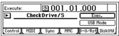
In the [SYSTEM/USB] "DiskUtil" tab page, select "USB Mode" and press the [ENTER] key.
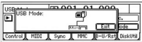
Do not disconnect the USB cable or turn your computer on/off while this screen is displayed.
③ A drive named "KORG D1200" will appear on your computer.
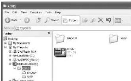
④ Use your computer to back up the data. When you open the "KORG D1200" drive that appeared in step ③, you will see the contents of the USB drive area within the D1200's internal hard disk. Copy the desired data onto your computer. You may also copy data from your computer back to the D1200's USB drive.
⑤ Disconnect the D1200 from your computer. Left-click the ( ) icon that is displayed in the right side of your computer's taskbar.
From the menu that appears, left-click "Stop USB disk drive (KORG D1200)." Verify that you see a message of "Safely remove USB Mass Storage Device." Select the "Exit" button of "USB Mode" and press [ENTER]. After you have exited USB mode, unplug the USB cable from the D1200.
note If you are using Windows Me, "USB high capacity storage device" will be displayed as "USB drive."
Macintosh users (Mac OS9.0.4 or later)
① Use a USB cable to connect the D1200 to your computer. Connect the USB cable from your computer to the D1200's [USB] connector. Make sure that the connector is oriented correctly, and press it all the way in.
② Access the "USB Mode" screen. In the [SYSTEM/USB] "DiskUtil" tab page, select "USB Mode" and press the [ENTER] key.
Do not disconnect the USB cable or turn your computer on/off while this screen is displayed.
③ A drive named "KORG D1200" will appear on the desktop of your computer.
note When you connect the D1200 to your computer for the first time, a device driver will be installed.
④ Use your computer to back up the data. When you open the "KORG D1200" drive that appeared in step ③, you will see the contents of the USB drive area within the D1200's internal hard disk. Copy the
desired data onto your computer. You may also copy data from your computer back to the D1200's USB drive.
⑤ Drag the added drive into the trash. When you want to disconnect the D1200, either drag the drive from the desktop into the trash, or select the "Special" menu command "Eject." Select the "Exit" button of the "USB Mode" screen, press [ENTER] to exit USB mode, and then unplug the USB cable from the D1200.
MIDI
What is MIDI?
MIDI stands for Musical Instrument Digital Interface, and is a world-wide standard by which performance data can be exchanged between electronic musical instruments and computers.
1. MIDI connections
Use special MIDI cables to transfer MIDI data. Connect these cables between the MIDI connectors of the D1200 and the MIDI connectors of the external MIDI device with which you want to transfer data.
MIDI IN connector: Receives MIDI messages from another MIDI device. Connect this to the MIDI OUT connector of the external device.
MIDI OUT connector: Transmits MIDI messages from the D1200. Connect this to the MIDI IN connector of the external device.
MIDI channel settings
MIDI uses sixteen channels (1–16) to independently convey data to multiple MIDI devices. If the transmitting device is sending data on MIDI channel "1," the receiving device must also be set to MIDI channel "1" in order to receive this data. ( p.101: [SYSTEM/USB] "MIDI" tab page "GlobalCh")
2. MIDI messages used by the D1200
Note On (Note, velocity), aftertouch, pitch-bend: The D1200 uses these messages to control effects.
Program change: The D1200 uses these messages to switch scenes.
Control change: The D1200 uses these messages to control mixer and effect parameters.
MMC (MIDI Machine Control): MMC messages can be transmitted from the D1200 to control an external MMC-compatible sequencer or recorder. MMC messages can be transmitted from an external sequencer or recorder to control the D1200.
MTC (MIDI Time Code): MTC messages can be transmitted from the D1200 to synchronize an external sequencer or recorder. The D1200 can also receive MTC messages and synchronize to them.
About the MIDI implementation chart
The owner's manual of each MIDI device includes a MIDI implementation chart. This chart shows the types of MIDI message that the device can transmit and receive. When using two MIDI devices together, compare their MIDI implementation charts to verify that the devices will be able to communicate as you expect.
* A detailed explanation of the D1200's MIDI functionality can be found in the separate MIDI implementation. To obtain a copy of the MIDI implementation, contact your Korg distributor.
3. Using MIDI
Controlling the D1200 from a MIDI sequencer
Here's how you can use MMC messages transmitted from a MIDI sequencer to control D1200 operations such as stop, play, fast-forward, rewind, record, and locate.
Note You must use a sequencer that supports MMC. These operations cannot be performed from a sequencer that does not support MMC.
① Connect the MIDI cables.
Use a MIDI cable to connect your MIDI sequencer's MIDI OUT connector to the D1200's [MIDI IN] connector.
② Make settings on your MIDI sequencer so that it will transmit MMC to control an external device. For details, refer to the owner's manual of your MIDI sequencer.
③ Turn on MMC reception.
In the [SYSTEM/USB] "MMC" tab page, set "Select MMCMode" to "Receive."
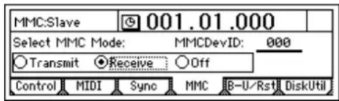
④ Set the correct device ID. Set "MMCDevID" to the MMC device ID of your MIDI sequencer.
note Since some MIDI sequencers indicate the MMC device ID in a different way, the ID may not necessary be a number.
⑤ Perform operations on your external MIDI sequencer. When you perform stop, play, fast-forward, rewind, record, and locate operations on your MIDI sequencer, the D1200 will be controlled. (For details, refer to the manual of your MIDI sequencer.)
Note You can transmit MTC (MIDI Time Code) or MIDI Clock messages from the D1200 to control the timing of your MIDI sequencer, while the sequencer controls stop, play, fast-forward, rewind, record, and locate operations on the D1200.
Synchronizing two D1200 units
Here's how you can make two D1200 units play back in synchronization. One D1200 will be the master, and the other will be the slave.
① Set the master D1200 so that it will transmit MMC and MTC.
In the [SYSTEM/USB] "Sync" tab page, set "Select MIDI SyncMode" to "MTC Mstr." In the [SYSTEM/USB] "MMC" tab page, set "Select MMC Mode" to "Transmit."
For this example, set "MMC DevID" to "10."
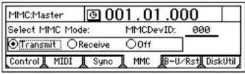
② Set the slave D1200 so that it will receive MMC and MTC.
In the [SYSTEM/USB] "Sync" tab page, set "Select MIDI SyncMode" to "MTC Slave." In the [SYSTEM/USB] "MMC" tab page, set "Select MMC Mode" to "Receive." Set "MMC DevID" to the same setting as the master ("10"). On the slave D1200, press the [PLAY] key to enter play-ready mode.
Note If you do not want the slave D1200 to receive mixer control messages, you can either set the master D1200 so that it will not transmit these messages, or set the slave D1200 so that it will not receive these messages (→ "Using MIDI for mixer control").
③ Press the [PLAY] key on the master D1200.
The slave D1200 will receive time code, and will begin playing as soon as it achieves synchronization with the master D1200.
note It may take several seconds for synchronization to be achieved.
Using MIDI for mixer control
In the [SYSTEM/USB] "MIDI" tab page, you can set "Control Change: Trans" or "Recv" to "ON" so that the D1200 will transmit or receive mixer parameters.
Recording the D1200's mixer control messages
Here's how D1200 mixer operation data can be recorded on an external MIDI sequencer. Connect the D1200 and MIDI sequencer as follows.
① Make synchronization settings on the D1200 and external MIDI sequencer.
Set the D1200 to be the master, and the external MIDI sequencer to be the slave. Make settings so that the MIDI sequencer will synchronize to the MIDI clock or MTC messages transmitted from the D1200. ( p.102)
② Enable control change transmission from the D1200. In the [SYSTEM/USB] "MIDI" tab page, turn the "Mixer Control" setting "Control Change: Trans" to "ON."
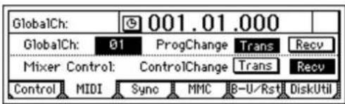
③ Put the external MIDI sequencer in record-ready mode. The D1200's mixer control data is transmitted on MIDI channels 1–12, corresponding to tracks 1–12. Make settings on your external MIDI device so that it will record all MIDI channels 1–12. (For details, refer to the owner's manual of your MIDI sequencer.)
Note For details on the parameters, refer to the MIDI implementation. To obtain a copy of the MIDI implementation, contact your Korg distributor.
④ Begin recording.
Press the D1200's [PLAY] key to begin playback, and the external MIDI sequencer will begin recording in synchronization. If you now operate the mixer parameters (faders, pan, EQ etc.), the corresponding control change messages will be transmitted from the D1200 and will be recorded on the external MIDI sequencer.
⑤ Stop the D1200. When you press the D1200's [STOP] key to stop play-back, the external MIDI device will also stop recording. The D1200's mixer parameter operations have now been recorded on the external MIDI device.
Using MIDI to control the D1200's mixer
Here's how the mixer control data that was recorded in "Recording the D1200's mixer control messages" can be transmitted back to the D1200 to control its mixer. Make connections as described in step ① of "Controlling the D1200 from a MIDI sequencer."
① Make synchronization settings for the D1200 and the external MIDI sequencer.
Make the settings described in step ① of "Recording D1200 mixer control data."
② Enable control change reception by the D1200. In the [SYSTEM/USB] "MIDI" tab page, set the "Mixer-Control" parameter "Control Change: Recv" to "ON."
③ Put the external MIDI sequencer in play-ready mode.
④ Start playback on the D1200.
When you press the D1200's [PLAY] key to begin play-back, the external MIDI sequencer will begin playing in synchronization. The previously-recorded mixer control data will be transmitted from the MIDI sequencer, and the mixer settings of the D1200 will change.
Upgrading the system
1. Downloading the system file
The most recent system file can be downloaded from the Korg website (www.korg.com). For details on the procedure, refer to the Korg website.
Upgrading via CD-ROM/R/RW
Insert the media containing the system file into the CDRW-1.
Upgrading via USB
Use a USB cable to connect the D1200 to your computer, and copy the system file to the root folder (the same location as the KORG folder) of the USB drive.
2. Upgrading the system
① Load the system file.
In the [SYSTEM/USB] "DiskUtil" tab page, use "SelOperation" to choose either "LoadSystem/C" if loading from a CD-ROM/R/RW, or "LoadSystem/U" if loading from the USB drive.
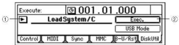
② Execute loading of the system file.
Press the "Exec." button. In response to "AreYouSure?," press the [YES/OK] key to begin loading.
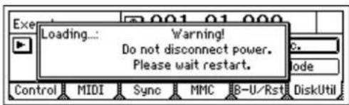
If the power is turned off or fails due to an unexpected accident while the system is being loaded, the D1200 may no longer operate correctly. If this occurs, contact your Korg distributor.
③ If the system file was loaded correctly, the D1200 will begin updating the system.
The [TRACK STATUS] LEDs will successively light from 1 to 11/12.
First the green LEDs will successively light from CH1 to CH11/12, and then the red LEDs will successively light from CH1 to CH11/12. Then the D1200 will automatically restart, and will begin operating with the new system.
If the system file is found to be invalid, the [TRACK STATUS] LED will not light, and the D1200 will restart.
After the D1200 restarts, perform the system update once again. If the update fails again, please contact your Korg distributor.
Reference
This section contains a detailed explanation of each screen that appears in the display when you press a key.
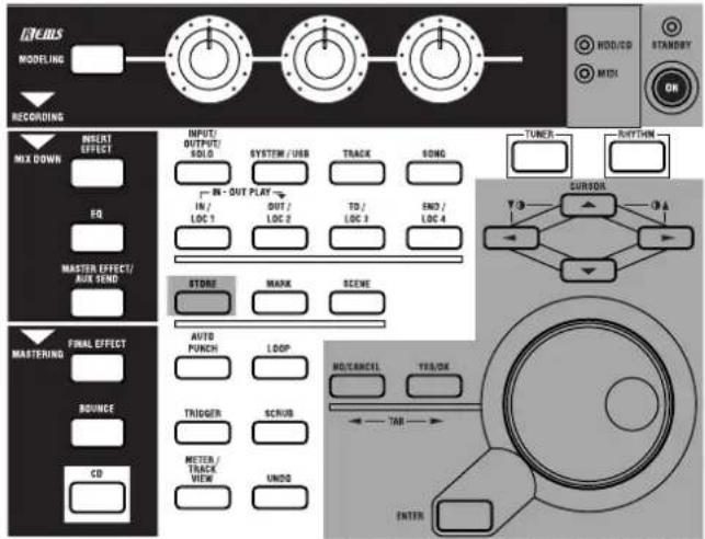
(COUNTER)....84 Counter: Counter display....84
MODELING....84 Category: Select an effect category ....84 Modeling 1....84 Modeling 2....85
INSERT EFFECT ....85 InsAss: Specify the insert location and type of the insert effects....85 InsEff1: Select and edit insert effect 1....86 InsEff2: Select and edit insert effect 2....87 InsEff3: Select and edit insert effect 3....87 InsEff4: Select and edit insert effect 4....88 InsEff5-8: Select and edit insert effects 5-8....88
EQ....88 Eq1–4: Adjust the EQ for mixer channels 1–4....88 Eq5–8: Adjust the EQ for mixer channels 5–8....88 Eq9–12: Adjust the EQ for mixer channels 9–12....89
MASTER EFFECT/AUX SEND....89 MstEff1: Select and edit master effect 1....89 MstEff2: Select and edit master effect 2....90 EffSnd1: Adjust send levels to master effect 1....90 EffSnd2: Adjust send levels to master effect 2....90 AuxSend: Adjust the external send levels....90
FINAL EFFECT ....91 FinalEff: Select and edit the final effect ....91
BOUNCE....92 RecMode: Select the recording mode....92 Bounce: Parameters for bounce-recording....92
CD....93 Prepare: Prepare to create an audio CD....93 CDR/RW: Create and play back an audio CD....93
TUNER ....95 RHYTHM ....95 SetUp: Specify the tempo and rhythm ....95 TmpMap: Tempo map editing ....96 TmpTrk: Create a tempo track....97
INPUT/OUTPUT/SOLO....98 Ch1-6: Select inputs for mixer channels 1–6....98 Ch7-12: Select inputs for mixer channels 7–12....98 InEq1-4: Adjust the EQ for inputs 1–4....99 Solo: Select the signal to be soloed....99
Monitor: Parameters and settings .... 100 Phase: Specify the phase of the mixer channels .... 100
SYSTEM/USB 101 Control: Foot switch and control change device (pedal/MIDI) settings....101 MIDI: MIDI settings....101 Sync: Synchronization settings....102 MMC: MMC settings....102 B-U/Rst: Backup and restore....102 DiskUtil: Disk drive management....105
TRACK....108 Vtr1-6: Select virtual tracks 1-6....108 Vtr7-12: Select virtual tracks 7-12....108 EditTrk: Perform track editing operations....108 Import: Import WAV files....113 Export: Export a WAV file....114
SONG .... 116 SelSong: Select a song.... 116 EditSong: Perform song edit operations .... 116 PrgPlay: Program playback of songs.... 118
IN/LOC1, OUT/LOC2, TO/LOC3, END/LOC4 .... 118 MARK .... 119 Mark: Edit marks .... 119
SCENE....120 ReadDel: Switch scene playback on/off, and edit scenes 120 MixView: Viewing pan and fader scene data....121
AUTO PUNCH....122 AtPunch: Settings for auto punch-in/out recording....122 LOOP....123 Loop: Settings for loop playback and recording....123
TRIGGER 123 Trigger: Settings for trigger recording 123
SCRUB....124 METER/TRACK VIEW....125 UNDO....126
(COUNTER)
Counter: Counter display
The counter in the upper right of each page indicates the current location in the song.
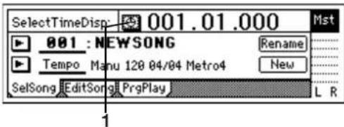
1. Select TimeDisp Type
Select the "button to open the "Select TimeDisp Type" dialog box. Select the type of counter to be shown in the display, and press the [YES/OK] key.
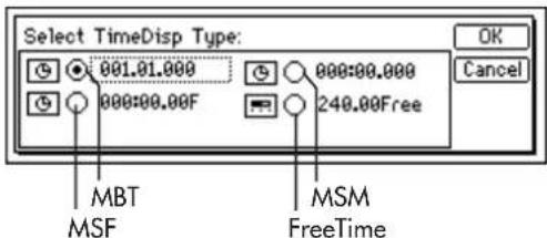
___.__.(MBT): The current location will be shown as the number of measures from the beginning of the song.
From the left, the values indicate Measures, Beats, and Ticks (1/96th beat).
_: ____(MSM): The current location will be shown as the absolute time from the beginning of the song. From the left, the values indicate Minutes, Seconds, and Milliseconds (1/1000th second).
_:._.F (MSF): The current location will be shown as the absolute time and number of frames from the beginning of the song. You will normally use this when synchronizing with MTC.
From the left, the values indicate Minutes, Seconds, and Frames (1/30th second).
___. Free (FreeTime): The remaining available recording time on the hard disk will be shown.
From the left, the values indicate Minutes and Seconds, or Minutes.
Note To change the current time location, move the cursor to a counter value and use the [VALUE] dial to change the value. (−p.32)
Note If the counter display is set to "Free," the time will be displayed as absolute time (MSM) in the STORE, MARK, SCENE, A.PUNCH, LOOP, and SCRUB pages.
MODELING
This lets you apply an effect to a guitar, bass or mic connected to the [GUITAR IN] jack or [INPUT 1] jack, and begin recording.
Category: Select an effect category
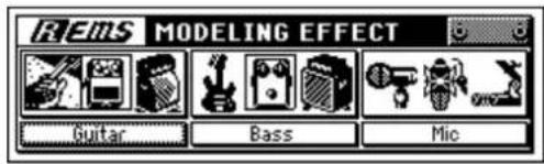
1. Select Modeling Effect Category ..... [Guitar, Bass, Mic]
Selects either guitar, bass, or mic as the type of modeling effect to be used.
Move the cursor to the desired category and press the [ENTER] key. The effects of the selected category will appear, and you will enter Modeling mode.
Modeling 1
As an example, here are the settings that will appear if you select a Guitar modeling effect.
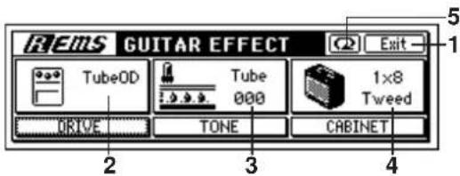
- Exit......
Return to the effect category select screen, and exit Modeling mode. (The [MODELING] key LED will go dark.)
2. Select DRIVE.....[(\*10 types)]
*TubeOD, ClassicDist, FatDist, MetalDist, Seattle, BigFuzz, TopBoost, US-HiGain, BritStack, Direct Selects the type of distortion.
Turn the knob located below "DRIVE" to select the desired type. You can also select the type by moving the cursor to "DRIVE" and turning the [VALUE] dial.
3. Select Tube Type..... [000...100]
Adjusts the vacuum tube character. Turn the knob located below "TONE" to make adjustments. You can also adjust the character by moving the cursor to "TONE" and turning the [VALUE] dial.
4. Select CABINET ....[(\*12 types)]
*1x8Tweed, 1x12Tweed, 1x12Black.P, 1x12AC15, 2x12Black.P, 2x12AC30, 2x12ClassicA, 4x10Tweed, 4x12Classic, 4x12Vintage, 4x12Modern, FullRange Selects the type of cabinet.
Turn the knob located below "CABINET" to select the desired type.
You can also select the type by moving the cursor to "CABINET" and turning the [VALUE] dial.
5. Factory Data....
Returns the selected modeling effect to the factory settings.
Modeling 2
If you want to make more detailed adjustments, move the cursor to "DRIVE," "TONE," or "CABINET," and press the [ENTER] key.
As an example, here are the settings that will appear if you select "DRIVE."
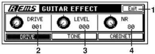
1. Exit......
Returns to the Modeling 1 screen.
2. DRIVE ....[001...100]
Adjusts the depth of distortion.
- T urn the knob located below "DRIVE" to adjust the setting.
- You can also adjust the setting by moving the cursor to "DRIVE" and turning the [VALUE] dial.
3. LEVEL..... [000...100]
Adjusts the volume of the effect.
- T um the knob located below "TONE" to adjust the setting.
- You can also adjust the setting by moving the cursor to "TONE" and turning the [VALUE] dial.
4. NR(NoiseReduction)..... [01...80]
Adjusts the level at which noise reduction is applied.
- T urn the knob located below "CABINET" to adjust the setting.
- You can also adjust the setting by moving the cursor to "CABINET" and turning the [VALUE] dial.
INSERT EFFECT
You can apply insert effects to analog input sources as you record them, or to the playback of a tracks.
On the D1200 you can use up to eight insert effects simultaneously.
Insert effects cannot be used if "Digiln" has been turned "On" in the [INPUT/OUTPUT/SOLO] "Ch1-6" or "Ch7-12" tab page.
InsAss: Specify the insert location and type of the insert effects
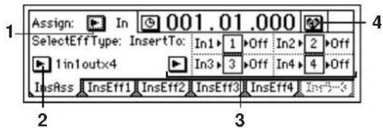
1. Assign ...... [In(Input), Trk(PlayTrack)]
Selects whether the insert effect will be applied to the analog input or to a playback track.
In (Input): Select this when you want to apply an effect to the analog input from an [INPUT 1/GUITAR IN]–[INPUT 4] jack.
Trk (PlayTrack): Select this when you want to apply an effect to a playback track.
2. SelectEffType ..... [1in2outx2, 2in2outx2, 1in1outx4, 1in1outx8]
Selects the structure of the insert effects. The available effect programs will depend on this setting. For the effects that are available with each structure, refer to "Effect Program List" ( p.154).
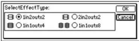
1in2outx2 or 1in1outx2: Select this when you want to use two mono-in/stereo-out effects.
This is ideal when you want to add spaciousness to a lead guitar or vocal. The effects can also be used as 1-in/1-out monaural effects.
You cannot select this if "Assign" is set to "Trk"
2in2outx2: Select this when you want to use two stereo-in/stereo-out effects.
This is ideal for use with stereo input sources such as keyboard.
1in1outx4: Select this when you want to use four mono-in/mono-out effects.
This is ideal for sources with a fixed pan position, such as rhythm guitar.
1in1outx8: Select this when you want to use eight mono-in/mono-out effects.
This is ideal for sources with a fixed pan position, such as drums.
You cannot select this if "Assign" is set to "In."
3. InsertTo....
Selects the location at which the insert effect will be inserted.
Press the "button to open the dialog box, and make settings. Press the [YES/OK] key to execute the settings. If you press the [NO/CANCEL] key, the settings will be cancelled.
The insertion location setting of the lowest-numbered effect will take priority. For example if you set effect number 1 to the same setting that was already made for effect number 4, the setting for effect number 4 will be cancelled. A setting that has already been made for effect number 1 cannot be selected for another effect number.
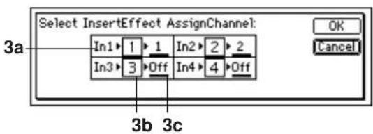
■ When "Assign" is set to "In"
Specifies the return channel.
3a. Input ......(In1...4, DrL, DrR, CL, CR, Off)
Indicates the input jack into which the effect is inserted. (→p.98)
3b. Effect ...... (1...4)
Indicates the effect number.
3c. SelectCh .... [Off, 1...12]
Specifies the channel to which the effect output will be returned.
■ When "Assign" is set to "Trk"
Specifies the insertion channel → (effect) → (return = insertion channel).
3a. SelectCh .... [Off, 1...12]
Selects the mixer channel into which the effect is inserted.
note If "SelectEffType" is "2in2outx2," only odd-numbered channels can be selected in "SelectCh."
3b. Effect ..... (1...8)
Indicates the insert effect number.
3c. OutputCh .... (Off, 1...12)
Indicates the channel to which the effect output is returned. This will indicate the same channel as "3a.SelectCh."
4. Pair ....
Specify pairing for adjacent mixer channels. Press the "button to access the following display.
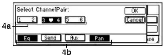
For channels that are paired, the odd-numbered knob or fader will control both channels. Moving the even-numbered knob or fader will not control anything.
4a. Select ChannelPair .... [1 2...5 6]
To specify the channels you want to pair, press a "1 2"- "5 6" button to turn it on. (The heart icon will appear.)
4b. Select Function .... [Eq, Send, Aux, Pan]
Select the function(s) for which pairing will be enabled. Use the "EQ"-Pan" buttons to turn on the functions that you want to pair. The settings will be applied when you press the [YES/OK] key.
note Fader and track status will always be paired if pairing is on.
InsEff1: Select and edit insert effect 1
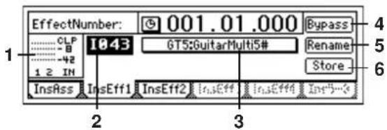
1. InputLevelMeter..... (IN1, 2/CLP, -8, -18, -42dB)
Indicates the input level of each effect. The horizontal axis indicates the effect input, and the vertical axis indicates the level. "IN2" is input only when [INSERT EFFECT] "InsEff1" is set to "2in2outx2," and will not be input otherwise.
2. EffectNumber..[000, 001...128, U001...128, (#)]
Selects the effect program.
"U001"- "U128" is the user area, in which you can save effect programs that you edited.
If the effect program includes a control function, a “#” will be displayed after the effect name. This will be displayed only for the insert effect assigned to the “Ass(#)” parameter of the [SYSTEM/USB] “Control” tab page.
Note The effects that you can select will depend on the "SelectEffType" setting in the [INSERT EFFECT] "InsAss" tab page. For details on the effects for each structure, refer to "Effect Program List" (→p.154).
3. EditEffect...... (EffectProgramName)
When you press this button, the "Effect Algorithm" dialog box will appear, showing the structure of the program, and allowing you to turn each effect on/off. An insert effect can consist of up to five effects.
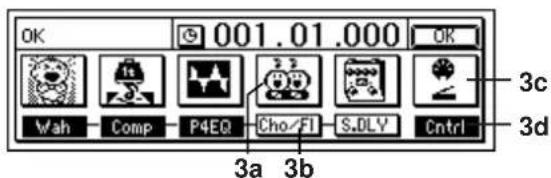
3a. Effect Icon ....
Selects the effect that you want to edit.
When you press an "EffectIcon" button, the "Effect Edit" dialog box will appear.
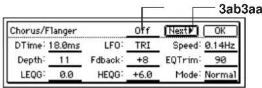
For details on each parameter, refer to "Effect Parameter List" (→p.127).
3aa. Effect On/Off.....[On, Off]
The "On/Off" setting in the display is linked with "Effect On/Off" (3b).
3ab. Next......
Displays the next page.

3ac. Prev ....
Displays the previous page.
3b. Effect On/Off.....[On, Off]
Switches each effect on/off.
Cho/FL On: Turns the effect on.
Cho/FL Off: Turns the effect off.
3c. Control Device ....
Lets you specify the effect parameter that will be controlled by the control device, and the maximum and minimum values.
This will be displayed only if you have set "Ass" to "InsEff1" - "InsEff4" in the [SYSTEM/USB] "Control" tab page.
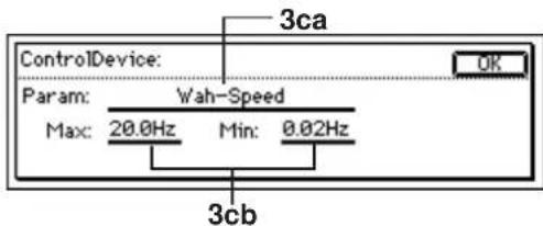
3ca. Parameter ....
Selects the parameter that will be controlled.
3cb. Max, Min ....
Specifies the maximum and minimum parameter values that will be controlled by the controller.
3d. Control On/Off ......(On, Off)
Indicates the effect control status.
Cntrl On: A "Parameter" is specified in the "Control Device" window.
Ctrl Off: "Parameter" is set to "Off" in the "Control Device" window. External control will not be possible.
4. Bypass......
Compares the sound of the effect with the unprocessed sound. When you press the "Bypass" button, the effect will be bypassed.
Press the [NO/CANCEL] key to defeat bypass.
5. Rename ....
Edits the name of the effect program.
Select the effect program whose name you want to edit, press the "Rename" button to open the dialog box, and edit the name. You can input a name of up to sixteen characters. (→p.31)
After editing the program name, use "Store" to store the program. Unless you perform the "Store" operation, the program name you edited will be discarded.
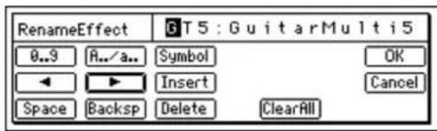
6. Store....
Stores the edited effect program in one of the user areas "U001" - "U128."
The D1200 provides 128 user areas in which you can store insert effects.
In the "StoreEffect" dialog box, specify the "user area number," and use the "Exec." button or the [YES/OK] key to store the program. Press the [NO/CANCEL] key if you want to cancel.
Effect programs are always overwritten onto the data that was previously in that location.
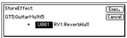
InsEff2: Select and edit insert effect 2
Here you can make selections and settings for insert effect 2. Refer to "InsEff1: Select and edit insert effect 1" (→p.86).
InsEff3: Select and edit insert effect 3
Here you can make selections and settings for insert effect 3. This will be displayed only if you set "SelectEffType" to "1in1outx4" or "1in1outx8" in the "InsAss" tab page (→p.85).
Refer to "InsEff1: Select and edit insert effect 1" (→p.86).
InsEff4: Select and edit insert effect 4
Here you can make selections and settings for insert effect 4. This will be displayed only if you set "SelectEffType" to "1in1outx4" or "1in1outx8" in the "InsAss" tab page (→p.85).
Refer to "InsEff1: Select and edit insert effect 1" (→p.86).
InsEff5-8: Select and edit insert effects 5-8
Here you can make selections and settings for insert effects 5–8.
This will be displayed only if you set "SelectEffType" to 1in1outx8" in the "InsAss" tab page (→p.85).
For insert effects 5–8, use "SelectEffect5...8" to select an effect, and then edit it.
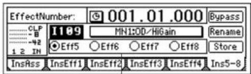
1
1. SelectEffect5...8 ....[Eff5, Eff6, Eff7, Eff8]
Select the insert effect 5–8 that will be displayed in this page. Editing, bypass settings, and rename etc. will apply only to the effect that is shown here.
For other details, refer to "InsEff1: Select and edit insert effect 1" (→p.86)
EQ
Eq1-4: Adjust the EQ for mixer channels 1-4
Here you can apply EQ (equalization) to the playback of mixer channels 1–4. Make these settings when you want to apply EQ to the playback.
This is a three-band EQ with shelving-type high and low bands, and a mid-EQ with adjustable center frequency.
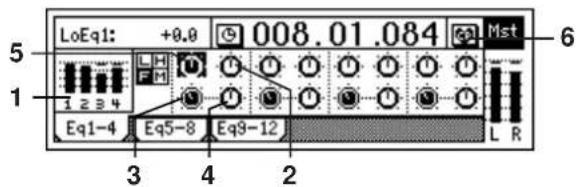
1. TrackLevelMeter ..... (1, 2, 3, 4/CLP, -8, -18, -42dB)
Displays the input level from each track. The horizontal axis indicates the channel, and the vertical axis indicates the level.
2. HighEq ....[ (Fc=10kHz)-15.0...+15.0(dB) ]
Specifies the gain of the high EQ. This adjusts the high-frequency range of the sound.
This setting lets you boost or cut the region above 10 kHz in a range of -15.0 - +15.0 dB.
3. MidFc .... [100Hz...20.0k(Hz)]
Specifies the center frequency of the mid EQ, in a range of 100 Hz–20.0 kHz.
4. MidEq....[-15.0...+15.0(dB)]
Specifies the gain of the mid EQ. This adjusts the mid-frequency range of the sound.
This setting lets you boost or cut the region specified by MidFc in a range of -15.0 - +15.0 dB.
5. LowEq ....[ (Fc=100Hz)-15.0...+15.0(dB) ]
Specifies the gain of the low EQ. This adjusts the low-frequency range of the sound.
This setting lets you boost or cut the region below 100 Hz in a range of -15.0 - +15.0 dB.
6. Pair
Pairs adjacent mixer channels. ( p.38, 86)
Eq5-8: Adjust the EQ for mixer channels 5-8
Here you can apply EQ (equalizer) to the playback of tracks 5–8.
Refer to "Eq1-4: Adjust the EQ for mixer channels 1-4."
Eq9–12: Adjust the EQ for mixer channels 9–12
Here you can apply EQ (equalizer) to the playback of tracks 9–12.
Refer to "Eq1-4: Adjust the EQ for mixer channels 1-4."
MASTER EFFECT/AUX SEND
By adjusting the send levels of each channel, you can send its signal to one or both master effects and use them to add overall depth and balance. The D1200 has two master effects, and both can be used simultaneously.
Use AUX send if you want to apply an external effect.
MstEff1: Select and edit master effect 1
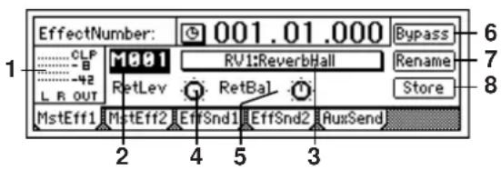
- OutputLevelMeter..... (OUT L, R/CLP, -8, -18, -42dB)
Indicates the output level of the effect.
The horizontal axis indicates the effect output, and the vertical axis indicates the level.
note The send level from each channel (i.e., the input level to the effect) can be adjusted in the "EffSnd1" tab page.
- EffectNumber .. [M000, M001...032, u001...032]
Selects the effect program.
"u001"- "u032" are user area programs in which you can store the effect programs you edit.
- EditEffect...... (EffectProgramName)
When you press this button, the "Effect Algorithm" dialog box will appear. Here you can view the structure of the program, and switch the effect on/off.
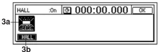
3a. EffectIcon ....
3b. Effect On/Off..... [On, Off]
(→p.86: Insert effect "EffectIcon," "Effect On/Off")
- RetLev.....[000...100]
Adjusts the return level from the master effect to the master bus.
As you increase this value, the effect will be applied more deeply.
- RetBal.....[L63...CNT...R63]
Adjusts the return balance from the master effect to the master LR bus.
"L" and "R" indicate the left and right channels of the master bus.
6. Bypass ....
(→p.87: Insert effect "Bypass")
7. Rename....
Edits the name of the effect program. Select the effect program whose name you want to edit, press the "Rename" button to open the dialog box, and edit the name. You can input a name of up to sixteen characters. (→p.31)
After you edit the program name, use "Store" to save it. The effect program name you edited will be discarded if you fail to use "Store."
8. Store ....
Saves the edited effect program in one of the master effect user area memories "u001"-"u032."
In the "StoreEffect" dialog box, specify a "user area number," and use the "Exec." button or the [YES/OK] key to execute the Store operation. If you decide to cancel, press the [NO/CANCEL] key.
Effects are always overwritten.
MstEff2: Select and edit master effect 2
Select and make settings for master effect 2. For an explanation of the parameters, refer to "MstEff1: Select and edit master effect 1."
note The send level from each channel (i.e., the input level to the effect) can be adjusted in the "EffSnd2" tab page.
EffSnd1: Adjust send levels to master effect 1
Adjust the send level from each mixer channel to master effect 1.
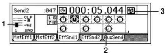
1. SendLevelMeter.....(SND 1/CLP, -8, -18, -42dB)
Indicates the send level to master effect 1. The vertical axis is the level.
2. Send.....[Ch1...6, 7-8...11-12/000...100]
Adjusts the send level from each mixer channel to master effect 1.
3. Pair ....
Specifies pairing for adjacent mixer channels. ( p.38, 86)
EffSnd2: Adjust send levels to master effect 2
Adjust the send level from each mixer channel to master effect 2.
For details, refer to "EffSnd1: Adjust send levels to master effect 1."
AuxSend: Adjust the external send levels
Adjust the send level at which each mixer channel is output from the [AUX OUT] jack.
For details on connecting and using an external effect, refer to p.45.
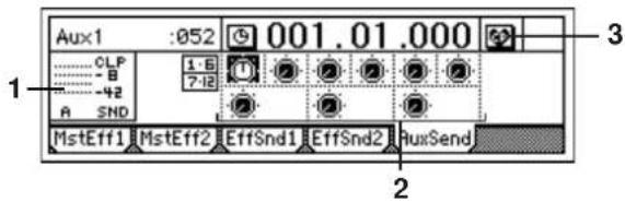
1. SendLevelMeter..... (SND A/CLP, -8, -18, -42dB)
Indicates the send level to the [AUX OUT] jack. The vertical axis is the level.
2. Aux......[Ch1...6, 7-8...11-12/000...100]
Adjusts the send level from each mixer channel to the [AUX OUT] jack.
3. Pair ....
Specifies pairing for adjacent mixer channels. ( p.38, 86)
FINAL EFFECT
The final effect is applied to the master LR bus to improve the overall balance of the song. The D1200 lets you use one stereo final effect.
FinalEff: Select and edit the final effect
The final effect is applied to the entire sound of the master output, and is used mainly to improve the overall balance of the completed song.
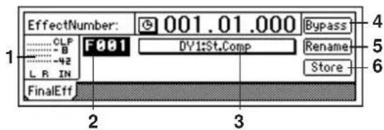
1. InputLevelMeter..... (InL, R/CLP, -8, -18, -42dB)
Indicates the effect input level. The horizontal axis indicates the effect input, and the vertical axis indicates the level. For details on adjusting the input level ( p.22).
2. EffectNumber..... [F000, F001...032, u033...064]
Selects the effect program. "u033"-"u064" is the user area, in which you can store effect programs that you have edited.
3. EditEffect...... (EffectProgramName)
When you press this button, the "Effect Algorithm" dialog box will appear. Here you can view the structure of the program and turn the effect on/off.
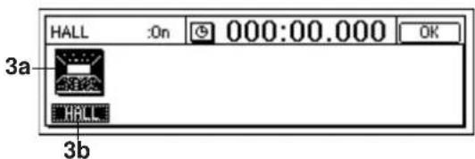
3a. EffectIcon ....
3b. Effect On/Off.....[On, Off]
Refer to "EffectIcon" and "Effect On/Off" for the insert effect (→p.86).
4. Bypass......
Refer to "Bypass" for the insert effect (→p.87).
5. Rename ....
Edits the name of the effect program. Select the effect program whose name you want to edit, press the "Rename" button to open the dialog box, and edit the name. You can input a name of up to sixteen characters. (-p.31)
After editing the program name, use "Store" to save it. The effect program name you edited will be discarded if you do not use "Store" to save your program.
6. Store......
Stores the edited effect program in one of the final effect user memories "u033"-"u064."
In the "StoreEffect" dialog box, specify the "user area number," and use the "Exec." button or the [YES/OK] key to execute. If you decide to cancel, press the [NO/CANCEL] key.
Effects are always overwritten.
BOUNCE
RecMode: Select the recording mode
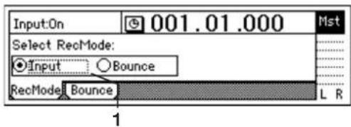
1. Select RecMode.....[Input, Bounce]
Selects the recording mode.
Input: Normal recording. The input (analog, digital, internal rhythm pattern, CD-R/RW drive) will be recorded. The channel faders will adjust the recording level of each track.
Bounce: Bounce-recording. The master LR bus will be recorded. The channel faders will adjust the playback level of each track, and the master fader, final effect will adjust the recording level.
If you select "Bounce," two tracks will always be recorded simultaneously.
Bounce: Parameters for bounce-recording
For the bounce-recording procedure, refer to p.28, 29, 64.
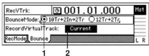
1. Select BounceMode ....[10Tr+2In→2Tr, 12Tr→2Tr]
Specifies the bounce-recording mode.
10Tr+2In→2Tr: Select this when you want to combine ten tracks of playback with two inputs, and record the combined result on two tracks.
The input signals you specify in the [INPUT/OUTPUT/SOLO] "Ch1-6" tab page and "Ch7-12" tab page will be valid for channels whose [TRACK STATUS] keys you set to REC (LED lit red), and will be recorded together with the playback tracks.
12Tr → 2Tr: Select this when you want to combine twelve tracks of playback and record the result on two tracks. The track playback for channels whose [TRACK STATUS] key is set to REC (LED lit red) will also be valid, and will be recorded along with the other playback tracks.
You can apply a master effect to multiple tracks as you combine them to two tracks. When creating an audio CD, perform bounce-recording as a mastering operation.
If you turn "Rhythm" "On" while using bounce-recording, the rhythm will also be recorded. (→p.48)
2. RecordVirtualTrack...... [Current, a...h]
Selects the virtual track on which recording will occur. This setting specifies which virtual track (of the recording tracks selected by the [TRACK STATUS] key) will be used for bounce-recording.
Current: The currently selected virtual track will be used for recording.
a...h: The specified virtual track will be used for recording. By using a virtual track "a"-"h" other that "Current," you can bounce-record to two virtual tracks without erasing any of the tracks 1–12.
However if the virtual track you select here is the same as the virtual track that has already been selected in [TRACK] "Vtr1-6" or "Vtr7-12," the result will be the same as if you had selected "Current."
To avoid accidentally recording over a track that has already been recorded, you should use the [TRACK] "Vtr1-6" and "Vtr7-12" tab pages to check on the virtual tracks that are currently selected and to see which virtual tracks already contain data.
CD
If you install the separately sold CDRW-1 option in the D1200, you will be able to create audio CDs. (→p.65)
The audio data from the first to the last of the two specified tracks of the currently selected song will be written to a CD-R/RW. Here you can also play back an audio CD.
For the CD writing method, you can choose either Track At Once or Disc At Once.
You can also retain the image file on the hard disk, to quickly write multiple copies of the CD.
Some audio CD players are unable to play back CD-R/RW discs.
Prepare: Prepare to create an audio CD
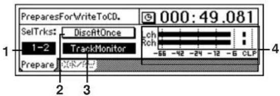
1. SelectTracks ..(1-2, 3-4, 5-6, 7-8, 9-10, 11-12)
Selects the tracks that will be written to the CD.
The audio data from the first to the last event of the selected track in the selected song will be written to the CD.
If you want to write the audio data from virtual tracks other than the ones that are currently selected, use the [TRACK] "Vtr1-6" and "Vtr7-12" tab pages to specify the desired virtual tracks, and then specify the tracks here.
2. DiscAtOnce ....[On, Off]
Switches the Disc At Once writing method on/off.
DiscAtOnce On: The disc will be written using the Disc At Once method.
From the first to the last events in the currently selected tracks of the currently selected song will be written to the CD-R/RW, and the disc will then be finalized – all in one operation.
The locations at which you have registered a Mark will be the track divisions of the CD.
If you write tracks 1 and 2 to the CD
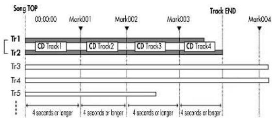
• There will be no space between the songs.
- When using Disc At Once, you can write only one song to disk. You will not be able to add other songs to the disc.
- Up to 99 marks are valid.
- The beginning of the selected track will automatically be the first song of the CD (track 1).
- You must register the marks so that each song (each track) written to the CD is at least four seconds long. If a song is less than four seconds long, an error will occur.
- Marks that are later than the end time of the selected tracks will be ignored.
DiscAtOnce Off: The disc will be written using the Track At Once method.
- Up to 99 marks are valid.
• Mark locations will not be used.
• Y ou may add other songs later. - If you want to play back the CD, you will need to perform the Finalize operation.
3. TrackMonitor.....[On, Off]
Lets you monitor the sound that will be written to the CD.
By turning this on and playing back, you can hear the audio of the tracks selected by "SelectTracks" without it being routed through the mixer (i.e., without EQ or effects). This lets you hear the sound that will actually be written to CD without having to adjust any settings.
note During playback, you will not be able to move to another tab page. If you want to move to another tab page, stop playback.
4. TrackMonitorLevelMeter.....
Indicates the track monitor level.
Watch the level meter to verify that the sound that will be written to CD does not clip, and that the level is not too low.
note This will be displayed if "TrackMonitor" is on.
CDR/RW: Create and play back an audio CD
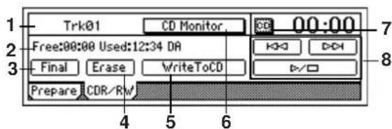
1. CD-R/RW Information ..... (Trk01...99, BlankDisc, NoAudioTracks, NoDrive)
Indicates the track that be played from the CD-R/RW disc.
Trk01...99: The track number on the CD-R/RW disc.
BlankDisc: An unused CD-R/RW disc is inserted.
NoAudioTracks: Either a CD-R/RW disc has not been inserted, or no playable audio tracks were found on the disc.
NoDrive: A CD-R/RW drive is not connected. Check that the CDRW-1 is installed correctly.
2. Size/DeviceType......(Free, Used/R, RW, DA)
Indicates the time that can be written on the CD-R/RW disc, and the type of disc.
Time display
Free: Indicates the free time on the disc.
Used: Indicates the used time on the disc.
The time is displayed in units of min (minutes): sec (seconds).
Disc type
R: The disc is a CD-R
RW: The disc is a CD-RW
DA: The disc is an audio CD
This corresponds to the following cases.
• A finalized CD-R created on the D1200 or other device
• A finalized CD-RW created on the D1200 or other device
• An audio CD
3. Final(Finalize)....
Finalizes the disc.
If you created a CD-R/RW disc using Track At Once and would like to play it on an audio CD player, you need to finalize the disc.
If you created the disc using Disc At Once, the disc is finalized automatically, so this step is not necessary.
Once a disc has been finalized, no further songs can be added to it. Execute the Finalize operation only after you have written all the desired songs to the disc.
4. Erase......
Erases all data that has been written to a CD-RW disc.
This cannot be performed on a CD-R disc. It is not possible to recover the data that is erased.
5. WriteToCD
Executes writing to CD-R/RW.
When you press the "WriteToCD" button, the "Obey Copyright Rules" dialog box will appear. Carefully read "COPYRIGHT WARNING" ( p.1), and use this function only if you accept the terms.
Press the [YES/OK] key to begin writing.
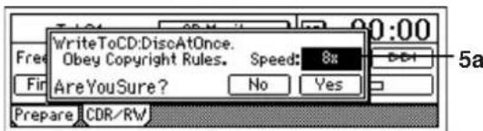
5a. Write Speed.....[1x, 2x, 4x, 6x, 8x]
Specifies the speed at which data will be written to the CD.
1x: Write at 1X speed.
2x: Write at 2X speed.
4x: Write at 4X speed.
6x: Write at 6X speed.
8x: Write at 8X speed.
After the data has been written, the following message will appear. If you want to write the same song to a different CD disc, press the [YES/OK] key. If not, press the [NO/CANCEL] key.
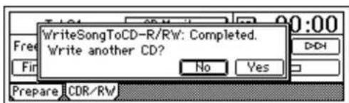
If you pressed the [YES/OK] key, the following message will appear, and the disc will be ejected from the CD drive. Insert another disc, and press the [YES/OK] key.
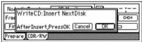
Since the image file still remains, it will take less time to create the second and subsequent discs.
Note The image file that is temporarily created before writing an audio CD will not change even if you change the writing speed.
Depending on your setup, writing at 4X or faster may not be successful. In this case, try a slower writing speed.
It is not possible to select a writing speed that the CDRW-1 does not support.
While the data is being written, you can select the "Abort" button and press the [ENTER] key to abort writing to the CD. In the case of a CD-R, the disc will become unusable. If you are using a CD-RW disc, perform the procedure described in "3. Erasing a CD-RW disc" (→p.76) before you use it.
6. CD Monitor ....[On, Off]
When an audio CD is inserted into the installed CDRW-1, this setting specifies whether the audio output of the CD will be sent to the monitor bus.
CD Monitor On: The sound of an audio CD inserted in the CDRW-1 will be output to the monitor bus. At this time, other audio will not be output from the monitor bus.
CD Monitor Off: CD monitoring will be off. The sound of the CDRW-1 will not be output to the monitor bus.
Note If you have made settings in the [INPUT/OUTPUT/SOLO] tab page to assign the CDRW-1 audio output to mixer channels, you will be able to hear the CD even if "CD Monitor" is turned off. In this case, the sound will be routed through the mixer (EQ and effects etc. will be applied).
7. CD......[Abs-Track, Abs-Total]
Selects how the CD-R/RW playback counter will be displayed.
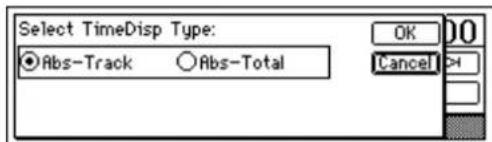
Abs-Track: Display the elapsed time for one song. Abs-Total: Display the elapsed time for the entire disc.
8. CD-R/RW transport keys
These keys let you play, stop, and select songs on the audio CD.
☐ : If in the middle of a track, move to the beginning of the track. If at the beginning of a track, move to the beginning of the previous track.
D:D : Move to the beginning of the next track. D:/□ : Play or stop the track.
TUNER
Here you can use the built-in tuner to tune an instrument connected to the [INPUT 1/GUITAR IN] jack.
You cannot select this page while recording or playing. Nor can you record while in this page.
note So that the pitch can be detected accurately, effects will automatically be turned off while this page is displayed.
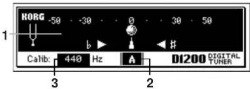
- CENT Scale ....(-50...+50)
When the tuning is correct, the "symbol will be at the 0 position in the middle of the meter, and the "flat indicator and "sharp indicator will both light. If the pitch is flat, only the "flat indicator will light. If the pitch is sharp, only the "sharp indicator will light.
The pitch deviation is displayed in units of cents. (100 cents is one semitone, and 1200 cents is one octave.)
- NoteDisplay.....(C...B)
Indicates the name of the note that is closest to the input pitch.
It is not possible to detect two or more pitches simultaneously.
- Calib ....[435...440...445Hz]
Adjusts the calibration frequency.
Normally you will leave this set to "440."
RHYTHM
Here you can make settings for the tempo, time signature, and rhythm (metronome) of the song.
If the counter is displaying "MBT" (measure, beat, 1/96th beat), the counter will operate according to the specified tempo.
Note Tempo/rhythm settings can also be made in the [SONG] "SelSong" tab page (→p.116).
SetUp: Specify the tempo and rhythm
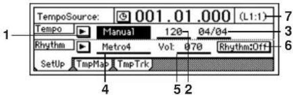
- TempoSource...... [Manual, TempoMap, TempoTrack]
Specifies the tempo source.
Press the "▶" button and make your selection in the dialog box that appears.
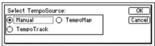
Manual: The current "Tempo" and "Beat" settings will be used. It will not be possible to automatically change the tempo, time signature, and rhythm pattern during the song.
TempoMap: The tempo, time signature, and rhythm pattern will change automatically during the song, according to the tempo maps you create. Use the "Tmp-Map" tab page to create tempo maps.
TempoTrack: The tempo will be determined by the recorded tap tempo or MIDI clock. Use the "TmpTrack" tab page to record tap tempo or sequencer tempo, and then select "TempoTrack" here.
The time signature will follow the settings you created in the "TmpMap" tab page.
note "TempoTrack" can be selected after the data is created.
- Tempo.....[40...240, (***)]
Specifies the tempo when "TempoSource" is set to "Manual."
If "TempoSource" is set to "TempoMap," this area will indicate the tempo for the current time location as specified by the tempo maps you created in the "TmpMap" tab page. If "TempoSource" is set to "TempoTrack," this area will indicate "***."
note The range is .=40-240.
- Beat..... [(01/04...16/16)]
Specifies the time signature when "TempoSource" is set to "Manual."
If "TempoSource" is set to "TempoMap" or "TempoTrack," this area will indicate the time signature for
the current time location as specified by the tempo maps you created in the "TmpMap" tab page.
4. SelRhythm ....[(Rhythm Pattern List)]
Specifies the rhythm pattern if "TempoSource" is set to "Manual."
If "TempoSource" is set to "TempoMap" or "TempoTrack," this area will indicate the rhythm pattern for the current time location as specified by the tempo maps you created in the "TmpMap" tab page.
Press the "button and select a rhythm pattern from the dialog box. The available rhythm patterns will depend on the "Beat" setting.
| 001: | Blank4 | L1 | OK | |
| 002: | Metro4 | L1 | Cancel | |
| 003: | Hihat4 | L1 | ||
| 004: | 8bt Rock1 | L1 |
5. RhythmVol ....[000...100]
Adjusts the rhythm volume that is sent to the master LR bus or the monitor LR bus.
In the [INPUT/OUTPUT/SOLO] "Monitor" tab page you can select the bus to which the rhythm is sent.
6. Rhythm.....[On, Off]
Switches the rhythm on/off.
RhythmOn On: The rhythm will be sent to the monitor LR bus or the master LR bus. Use the [INPUT/OUTPUT/SOLO] "Monitor" tab page "Rhythm" button to specify the bus to which the rhythm will be sent ( p.100). The [RHYTHM] key LED will light.
Rhythm:Off Off: The rhythm will not be sent to the monitor LR bus or the master LR bus.
During bounce-recording, the rhythm will be recorded if this is "On."
If you make settings in the [INPUT/OUTPUT/SOLO] "Ch1-6" or "Ch7-12" tab page to assign rhythm ("Rhythm L," "Rhythm R") to a mixer channel, the rhythm will sound during recording or playback, regardless of this setting.
If "Rhythm" is "On," the currently-selected rhythm will sound while this tab page is displayed, even if the recorder is stopped. The rhythm will continue sounding even if you move to the "METER/TRACK VIEW" tab page.
7. Pattern Length, Pattern Position ....
Indicates the number of measures (length) in the pattern selected by "SelRhythm," and the current measure within the pattern.
Example: (L4:1): Playing measure 1 of a four-measure pattern.
TmpMap: Tempo map editing
By creating tempo maps you can change the tempo, time signature, and rhythm pattern during the song while it plays or records.
For details on how to create tempo maps, refer to p.49.
Note Tempo, time signature, and rhythm changes can be placed only at the beginning of a measure.
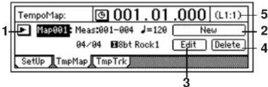
1. TempoMap.....[001...200]
Indicates the tempo map number that is selected. To the right of this number, the display shows the starting measure, ending measure, tempo, time signature, and rhythm pattern.
You can press the "button" button and make your selection in the dialog box that appears.
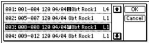
"TempoMap" cannot be selected if "TempoSource" is "Manual."
2. New......
Creates a new tempo map and adds the tempo map. The following "Select Tempo Map *** Param" dialog box will appear.
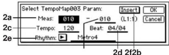
2a. StartMeas ....[001...999]
Specifies the starting measure for the tempo map that will be created.
2b. EndMeas..... [001...999]
Specifies the ending measure for the tempo map that will be created.
2c. Tempo ....[40...240]
Specifies the tempo in a range of ♩=40-240.
2d. Beat.....[01/04...16/16]
Specifies the time signature.
2e. Rhythm ....[(Rhythm Pattern List)]
Specifies the rhythm pattern. If you want the rhythm to be silent during part of the song, select a silent rhythm. Press the "button" button and make your selection in the dialog box that appears.
The available rhythms will depend on the "Beat" setting.
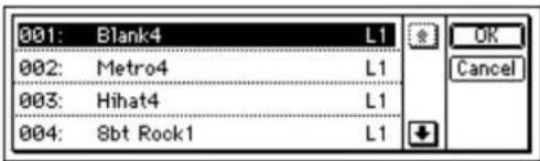
2f. Insert.....[On, Off]
Insert On: The new tempo map you create will be inserted. Turn this setting on if you want to add a pattern at the specified measure.
Insert Off: The new tempo map you create will overwrite the previous tempo map at this location. Turn this setting off if you want to replace the pattern at the specified measure.
3. Edit......
Edits the tempo map settings.
Select this when you want to edit an existing tempo map. Use "TempoMap" to select the tempo map that you want to edit, and then press this button. The "SelectTempo Map *** Param" dialog box will appear, allowing you to edit the settings.
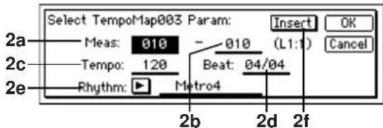
4. Delete......
Deletes a tempo map.
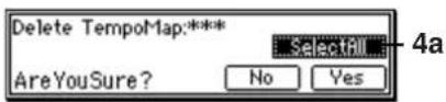
4a. SelectAll.....[On, Off]
Selects all tempo maps for deletion.
SelectAll On: All tempo maps will be deleted when you press "Yes." The tempo map number will be displayed as "***".
SelectAll Off: The single tempo map selected by "TempoMap" will be deleted when you press "Yes."
Tempo map number and measure number later than the deleted tempo map will be shifted towards the beginning of the song.
5. Pattern Length, Pattern Position......
Indicates the length (number of measures) of the rhythm pattern selected by "SelRhythm," and the currently-playing measure.
TmpTrk: Create a tempo track
There are two ways to record the tempo track.
- Record MIDI clock
You can record MIDI clock data from an external sequencer, in order to synchronize with the external sequencer data.
- Record tap tempo
If you do not know the tempo of the audio that is recorded on the D1200, you can record tap tempo data so that you will be able to manage and edit the audio data in units of measures.
For the procedure refer to p.51.
The above two types of tempo track cannot be maintained simultaneously; only the last-recorded type of tempo data will be held in the tempo track. If the memory becomes full while recording tempo data, recording will end automatically.
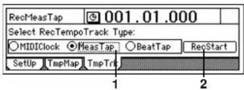
1. Select RecTempoTrack Type ...... [MIDIClock, MeasTap, BeatTap]
Selects the type of tempo track to be recorded.
MIDIClock: The tempo track will be created by recording MIDI clock data from a song created on an external sequencer.
MeasTap: The tempo track will be created by tapping at the beginning of each measure.
BeatTap: The tempo track will be created by tapping at the beginning of each beat.
2. RecStart....
Begin recording the tempo track.
INPUT/OUTPUT/SOLO
Ch1-6: Select inputs for mixer channels 1-6
Here you can select the inputs for mixer channels 1–6. For details on connecting each input jack, refer to p.14.
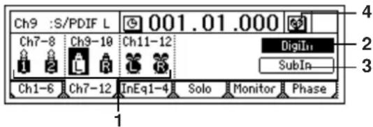
1. Ch1...6..... [Input1....4, S/PDIF L, R, RhythmL, R, CD L, R\*]
Select a "Ch1"–"Ch6" channel icon, and select the source that will be input to each channel.
INPUT1...4: Input the analog audio signal from an instrument etc. connected to the [INPUT 1/GUITAR IN]–[INPUT 4] jacks.
S/P DIF L, R: Input the digital audio signal from a CD or DAT etc. connected to the [S/P DIF IN] jack. This can be selected if "Digiln" is "On."
Insert effects cannot be used when using digital input.
RhythmL, R: Input the rhythm selected by
"SelRhythm" (→p.96). The rhythm will sound during recording and playback, regardless of the "Rhythm" setting (→p.96). This rhythm can be recorded (→p.48).
CD L, R: Input the audio signal from an audio CD inserted in the CDRW-1.
*CD L, R can be selected only if the CDRW-1 is installed.
2. Digiln ....[On, Off]
Turn this "On" when you want to use digital input (S/P DIF IN).
DigiIn On: You will be able to select "S/P DIF L" or "S/P DIF R" for "Ch1...6."
Insert effects cannot be used if this is "On."
DigiIn Off: You will not be able to select "S/P DIF L" or "S/P DIF R" for "Ch1...6."
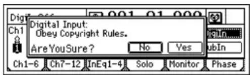
Turn this "On" if you want to use digital input (S/P DIF IN). When you press the "DigiIn" button, a message of "Obey Copyright Rules" will appear. Carefully read the section "COPYRIGHT WARNING" (→ p.1), and if you accept the terms, press the [YES/OK] key in response to "Are You Sure?" Digital input will be enabled.
3. SubIn......
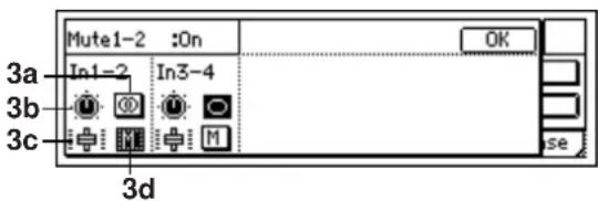
These settings let you use the [INPUT 1/GUITAR IN]-[INPUT 4] jacks as "sub inputs," for example when you want to use these jacks as the returns from an external effect device, or when you want the sound of instruments connected to these jacks to be combined with the track playback. (→p.67)
Sub input can be used when you want to synchronize an external sequencer with a completed song on the D1200, and mix the instrumental sounds played by the sequencer with the playback tracks of the D1200.
These inputs will be sent through the stereo/mono switch, balance, and fader to the master LR bus.
Note Use the [AUX OUT] jack to output the send signal to the external effect device. (→p.90: [MASTER EFFECT/AUX] "AuxSend" tab page)
3a. Stereo/Mono ....[Stereo, Mono]
Stereo: The odd-numbered channel input will be sent to the master L bus, and the even-numbered channel input will be sent to the master R bus.
Mono: The odd-numbered and even-numbered inputs will be combined, and the same signal will be sent to the master L and R buses. Use this setting if the input signal consists of only one channel.
If the sound is distorted when you use the "Mono" setting, adjust the level on the output device or using the [TRIM] knob.
3b. Balance ....[L63...CNT...R63]
Specifies the balance at which the sub input will be sent to the master LR bus in stereo.
3c. Fader ....[000...100]
Specifies the level at which the sub input will be sent to the master LR bus.
3d. Mute.....[On, Off]
M On: The sub input will be muted; it will not be sent to the master LR bus.
M Off: The sub input will not be muted; it will be sent to the master LR bus.
4. Pair ....
Specify pairing for adjacent mixer channels.
Press the "button, and make settings. (→p.38, 86)
Ch7-12: Select inputs for mixer channels 7-12
Here you can select the inputs for mixer channels 7–12.
Refer to "Ch1-6: Select inputs for mixer channels 1-6."
InEq1-4: Adjust the EQ for inputs 1-4
Here you can apply EQ (equalization) to the analog inputs from the [INPUT 1/GUITAR IN]-[INPUT 4] jacks. Use this when you want to record the sound with EQ applied. The EQ is a three-band type, with shelving-type high and low bands, and a peaking-type mid band with adjustable center frequency.
The input EQ cannot be applied to the digital input (S/P DIF IN) or to the rhythm.
The "InEq1-4" tab page settings cannot be paired.
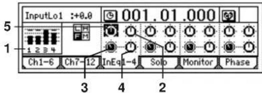
- InputLevelMeter.... (1, 2, 3, 4/CLP, -8, -18, -42 dB)
Indicates the level of each analog input. The horizontal axis indicates the channel, and the vertical axis indicates the level. Inputs that are not selected in the [INPUT/OUTPUT/SOLO] "Ch1...6" tab page will not be shown here.
- InputHigh..... [(Fc=10kHz) -15.0...+15.0 (dB)]
Sets the input high EQ gain. This will adjust the high-frequency range. The region above 10 kHz can be boosted/cut over a range of -15.0 - +15.0 dB.
- InMidFc.....[100Hz...20.0k (Hz)]
Specifies the frequency of the input mid EQ. The frequency can be adjusted over a range of 100 Hz–20.0 kHz.
- InputMid.....[-15.0...+15.0 (dB)]
Sets the input mid EQ gain. This will adjust the mid-frequency range. The region specified by InputMid can be boosted/cut over a range of -15.0 - +15.0 dB.
- InputLow.....[(Fc=100Hz) -15.0...+15.0 (dB)]
Sets the input low EQ gain. This will adjust the low-frequency range. The region below 100 Hz can be boosted/cut over a range of -15.0 - +15.0 dB.
Solo: Select the signal to be soloed
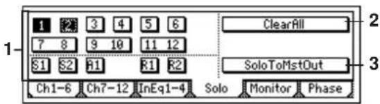
- SelectSolo ..... [1...6, 7-8...11-12, S1, S2, A1, R1, R2/On, Off]
Switches the solo function on/off. Only the audio signals for which the "Solo" button is on will be sent to the monitor LR bus. Use this when you want to hear only a specific audio channel out of many channels, or when you want to check the send signal. The solo signal will be output from the [MONITOR OUT L/R] jacks and from the [PHONES] jack. If even one of these solo buttons is "On," the [INPUT/OUTPUT/SOLO] key will blink.
1 On: Solo will be on. Only the corresponding signal will be heard.
1 Off: Solo will be off. If any other signal is being soloed, the corresponding signal will be muted.
1...6: Mixer channel 1-6
7-8...11-12: Mixer channels 7-8...11-12.
S1, S2: Send to master effects 1 and 2
A1: Send to the [AUX OUT] external output jack R1, R2: Return from master effects 1 and 2
The volume of each signal is set by the corresponding page or knob. When you select a different signal to be soloed, the monitor volume may change significantly.
- ClearAll ....
Turns "Off" all solo signals that are currently turned "On" by the "SelectSolo" buttons.
- SoloToMstOut.....[On, Off]
Specifies whether the soloed signal(s) will be output from the [MASTER OUT L/R] jacks. Turn this on if your monitor system is connected to the [MASTER OUT L/R] jacks and you want to solo through those jacks.
SoloToMstOut On: The solo signal(s) will be output from the [MONITOR OUT L/R] jacks.
SoloToMstOut Off: The solo signal(s) will be output from the [MONITOR OUT L/R] jacks and the [PHONES] jack.
The "On" setting is valid only while you are in the [INPUT/OUTPUT/SOLO] tab page. When you leave this page, the setting will automatically be turned "Off."
Monitor: Parameters and settings
Here you can select the audio signals that will be output from the monitor output ([MONITOR OUT L/R] jacks) and headphone output ([PHONES] jack).
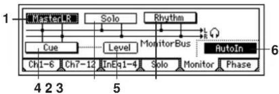
flowchart
graph TD
    A["Master R"] --> B["Solo"]
    B --> C["Rhythm"]
    C --> D["Monitor Bus"]
    D --> E["AutoIn"]
    F["Cue"] --> G["Level"]
    G --> H["Ch1-6"]
    G --> I["Ch7-12"]
    G --> J["InEq1-4"]
    G --> K["Solo"]
    K --> L["Monitor Phase"]
    style A fill:#f9f,stroke:#333
    style B fill:#ccf,stroke:#333
    style C fill:#cfc,stroke:#333
    style D fill:#fcc,stroke:#333
    style E fill:#cff,stroke:#333
    style F fill:#ffc,stroke:#333
    style G fill:#cfc,stroke:#333
    style H fill:#fcc,stroke:#333
    style I fill:#ffc,stroke:#333
    style J fill:#cfc,stroke:#333
    style K fill:#fcc,stroke:#333
    style L fill:#ffc,stroke:#333
1. MasterLR
Sends the master LR bus to the monitor output. Normally you will select this.
MasterLR On: Send the signal to monitor output. MasterLR Off: Don't send the signal to monitor output.
2. Solo
If even one signal is turned "On" in the "Solo" tab page, this will be selected automatically. It will not be possible to select "MasterLR" or "Cue." If you want to select these, you must first turn "Off" all soloed signals in the "Solo" tab page.
Solo On: Send the signal to monitor output. Solo Off: Don't send the signal to monitor output.
3. Rhythm.
Selects the bus to which the rhythm sound will be sent. Rhythm On: Send the rhythm to the monitor LR bus. Choose this setting when you want to output the track audio from the [MASTER OUT L/R] jacks, and listen to the rhythm only through headphones, such as during a live performance.
Rhythm Off: Send the rhythm to the master LR bus. If you choose this "Off" setting during bounce recording, the rhythm will be recorded.
note If you turn the "Rhythm" setting "Off" in the [RHYTHM] "SetUp" tab page, the rhythm sound will not be sent to any bus, regardless of this setting.
4. Cue
Sends the channels specified by the "Level" settings to the monitor output. During recording, you can use this to adjust the monitor volume and pan for comfortable listening without affecting the recording level.
Cue On: Send the signal to monitor output. Cue Off: Don't send the signal to monitor output.
5. Level (Cue Level)
Adjusts the level and pan for each mixer channel when "Cue" is turned "On."
Press the "Level" button to open the "Cue settings" dialog box and make settings.
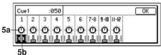
5a. Pan(Ch1D6)/Balance(Ch7D12)....[L63...CNT...R63]
Adjusts the pan or balance at which the cue signal from each channel will be sent to the monitor output.
5b. Cue ....[000...100]
Adjusts the volume at which the cue signal from each channel will be sent to the monitor output.
6. Autoln ....[On, Off]
Specifies whether mixer channels whose [TRACK STATUS] is REC will monitor the external source assigned in the "Input" tab page, or the playback of the track.
AutoIn On: Mixer channels whose [TRACK STATUS] is REC will monitor the external input assigned in the "Input" tab page when the track is recording or stopped, and will monitor the playback of the track when the track is playing.
AutoIn Off: Mixer channels whose [TRACK STATUS] is REC will always monitor the external input.
Phase: Specify the phase of the mixer channels
Here you can invert the phase of each channel. This applies to playback tracks. If audio equipment whose hot and cold pins were reversed have been recorded in stereo, you may experience problems such as an unstable stereo image or cancellation. You can correct such situations by inverting the phase of the signal.
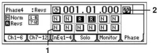
1. Phase ....[N, R]
N (Normal Phase): The phase of this channel will not be inverted. Normally you will use the "N" setting. R (Reverse Phase): The phase of this channel will be inverted.
2. Pair ....
Specifies pairing for adjacent mixer channels. (→ p.38, 86)
SYSTEM/USB
Control: Foot switch and control change device (pedal/MIDI) settings
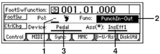
1. Pol(FootSwPolarity) ....[-, +]
Specifies the polarity of the foot switch.
Connect a foot switch (separately sold option: PS-1 or equivalent) to the front panel [FOOT SWITCH] jack, and set this parameter so that the "symbol lights when you press the foot switch.
2. Func(FootSwFunction) ......
[PunchInOut, Play/Stop, Mark]
Selects the function that will be controlled by the foot switch.
PunchIn-Out: Perform manual punch-in and punch-out (i.e., switch between recording and playback).
Set the [TRACK STATUS] key of the desired track to REC, and begin playback. Recording will begin the moment you press the foot switch, and will end when you press the foot switch once again. (→p.53)
Play/Stop: Switch between playback start and stop.
Press the foot switch to start playback, and press it again to stop playback.
Mark: Register a mark. When you press the foot switch, a mark will be registered at that time location.
While this tab page is displayed, the foot switch is used to detect the polarity, and the function selected here will not operate. Also, while recording tap tempo, the foot switch will be used for tap tempo input regardless of the setting you specify here. (→p.52)
3. Device(CtrlChgDevice)......
[Pedal, A.Touch, PitchBend, Velocity, NoteNum, CC#000...119]
Selects the external device that will control one of the D1200's internal effects. The effect you specify in "Ass" can be controlled in realtime.
Pedal: An expression pedal will control the effect. Connect an expression pedal (such as the separately sold XVP-10 or EXP-2) to the [EXPRESSION PEDAL] jack, and move the pedal to control the effect.
A. Touch, PitchBend, Velocity, NoteNum: MIDI after-touch, pitch bend, velocity, or note number data will control the effect.
Connect the MIDI OUT of an external MIDI device to the D1200's MIDI IN connector, and transmit the appropriate MIDI data from the external MIDI device to control the effect.
CC (Control Change) #000...119: A MIDI control change number will control the effect.
Connect the MIDI OUT of an external MIDI device to the D1200's MIDI IN connector, and transmit the appropriate MIDI control change message from the external MIDI device to control the effect.
4. Ass(CtrlChgAssign) ....[ExpOff, InsEff1...4]
Selects the insert effect that will be controlled.
The insert effect you select here will be controlled by the specified "Device."
ExpOff: No insert effect will be controlled.
InsEff1, InsEff2, InsEff3, InsEff4: Insert effect 1, 2, 3, or 4 will be controlled respectively.
If the effect program you are using does not have a control function, the effect will not be controlled. (→p.127-)
MIDI: MIDI settings
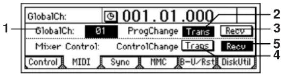
On the D1200 you can use MIDI to do the following things.
• Control effects ( p.44, 87)
- Synchronize with a sequencer or other MIDI device ( p.51)
- Switch scenes ( p.39)
- Use control changes to control mixer parameters
1. GlobalCh(GlobalChannel) .....[01...16]
Specifies the global MIDI channel.
If the D1200 is connected via MIDI to an external MIDI device, the D1200 will be able to exchange MIDI messages with the external device if its "GlobalCh" is set to match the MIDI channel of the external device.
Make this setting when you want to do the following things.
- Set "Device" to a MIDI message other than "Pedal," and control an effect from an external device.
- Use program change messages to transmit or receive D1200 scene changes.
2. ProgramChange: Trans....[On, Off]
Switches program change message transmission on/off. Program change messages will be sent when you switch scenes or execute a store or recall operation.
3. ProgramChange: Recv..... [On, Off]
Switches program change message reception on/off. When the D1200 receives a program change message, it will switch scenes.
4. ControlChange: Trans ....[On, Off]
Switches control change message transmission on/off. Control change messages will be transmitted when you operate a mixer parameter.
Control change messages transmitted from the D1200 can be recorded on an external MIDI sequencer.
5. ControlChange: Recv ...... [On, Off]
Switches control change reception on/off. Control change messages recorded on an external MIDI sequencer can be received by the D1200 to control the corresponding mixer parameters.
For details on the parameters that can be controlled, refer to the MIDI implementation chart ( p.160).
Sync: Synchronization settings
You can synchronize the D1200 with an external MIDI sequencer to make D1200 audio tracks play along with an external MIDI sound module.
"Synchronization" means that the D1200 and the external MIDI device will use the same clock signal to play back at the identical timing.
The device that outputs the synchronization clock is called the "master," and the device that receives this clock is called the "slave." The D1200 can function either as the master or slave.
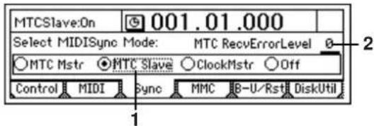
1. Select MIDISync Mode ...... [MTC Mstr, MTC Slave, ClockMstr, Off]
Selects the synchronization signal that will be transmitted and received from the [MIDI IN/OUT] connectors. MTC Mstr: The D1200 will function as an MTC30NDF (MIDI Time Code 30 non-drop frame) master device.
MTC Slave: The D1200 will function as an MTC30NDF (MIDI Time Code 30 non-drop frame) slave device.
ClockMstr: The D1200 will transmit MIDI Clock.
Off: The D1200 will not transmit or receive synchronization signals.
2. MTC RecvErrorLevel.....[0...9]
Specifies the level of tolerance with which the incoming MTC data will be checked when "Select MIDISync Mode" is set to "MTC Slave"
If due to some problem, the MTC data is not received in continuous succession, the D1200 will detect that there is a problem with the MTC data, and may cease synchronization and stop playback. If this occurs, you can lower the "MTC RecvErrorLevel" so that synchronized playback will continue even if slight problems occur with MTC reception.
note If you set this to "0," synchronization playback will not stop even if a problem occurs.
If you are synchronizing with a device other than the D1200 as the MTC master, incompatibilities between the devices may cause synchronization problems unless you play back from the beginning of the song.
MMC: MMC settings
The D1200 can transmit and receive MMC (MIDI Machine Control) messages.
This means that when synchronizing two 1200 units, or when using the D1200 with a MMC-compatible MIDI sequencer, you can control operations such as song playback, stop, and fast-forward from the master device.
Some MIDI devices may not support the MMC functionality of the D1200. For details on the MMC functionality of the D1200, refer to the MIDI implementation.
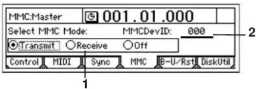
1. Select MMC Mode ....[Transmit, Receive, Off]
Switches MMC transmission/reception on/off.
Transmit: The D1200 will transmit MMC.
Receive: The D1200 will receive MMC.
Off: The D1200 will not use MMC.
2. MMCDevID(MMCDeviceID)..... [000...127]
Specifies the device ID that will be used to transmit and receive MMC.
In order to transmit or receive MMC, you must use a MIDI cable to connect the D1200 and the external MIDI device, set the two devices to the same Device ID, and make the appropriate setting in "Select MMC Mode."
If you set the device ID to "127," the D1200 will receive MMC messages of any ID number, and will transmit MMC messages using ID 127, to which all devices will respond.
B-U/Rst: Backup and restore
Here you can backup data to a CD-R/RW disc or the USB drive, and restore the backed-up data.
The following data can be restored.
• D1200 backup data
• D1600 backup data (track 1–12 data only)
• D12 backup data
• D16 backup data (track 1–12 data only)
Note For details on compatibility between these models, refer to p.68.
When backing up to CD-R/RW, it is not possible to save multiple sets of data on a single disc.
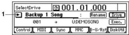
1. B-U/RstType.....[Backup1 Song, BackupAll Songs, BackupUserData, Restore]
Select the type of backup or restore operation.
Press the "button and make your choice in the dialog box.
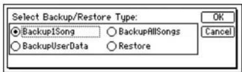
Each type of backup/restore operation is explained separately below.
B-U/RstType: "Backup1Song"
Backup the selected song and effect user data.
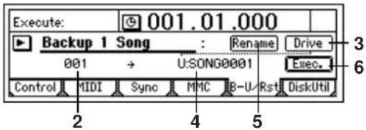
2. Source ...... (001...100)
Indicates the backup-source song number. This shows the number of the song that is selected in the [SONG] "SelSong" tab page. (→p.116)
3. Drive ....[S, C, U]
Selects the backup-destination drive. The drive ID, drive information (type and capacity), and format type will be displayed.
S: HDD: Hard disk song drive.
(This item cannot be used to backup or restore data.)
C: CD: CD-R/RW drive.
U: USB DOS: USB drive of the hard disk.
![S:HD038.8G C:CD [B] U:USB DOS Cancel](/content/2026/05/820878/images/98bd35146dc2399c6e40d995b3c520091b68d6d86e6a182499f4eaec46e548c7.jpg)
3a
3a. Format Type..... (B, D16[B], Audio)
Indicates the format type of the CD-R/RW disc.
[B] (Backup Type): D1200 or D12 backup CD
D16 [B]: D16 or D1600 backup CD
Audio: Audio CD
4. Destination ..(C, U:CDx01...99, SONG001...100)
Indicates the backup-destination drive and drive information (C:CD x required number of discs, or U:SONG-).

When backing up to CD-R or CD-RW, you must use blank discs.
5. Rename ....
If you set "Drive" to "U:USB-DOS," you can change the name of the backup-destination file. (→p.69)

You can input a filename of up to eight characters. Also, symbols and lowercase letters cannot be used.
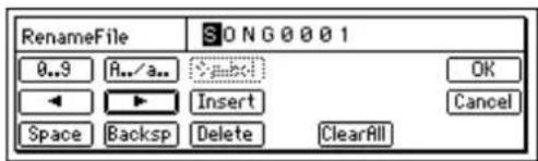
6. Exec.(Execute) ....
Executes the backup.
Effect user data will also be backed up at this time.
B-U/RstType: "BackupAllSongs"
Backup the hard disk song drive and the effect user data. This backup data can be saved only to a CD-R/RW disc.
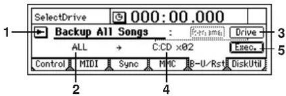
2. Source ....(ALL)
Indicates that all songs will be backed up.
3. Drive ....[S, C, U]
Selects the backup-destination drive. (→p.103) Select C:CD in this case.
4. Destination.....(C:CDx01...99)
Indicates the backup-destination drive and drive information (C:CD x required number of discs).
5. Exec.(Execute) ....
Executes the backup. Effect user data will also be backed up at this time.
5a. Speed ....[1x, 2x, 4x, 6x, 8x]
When backing up to CD-R/RW, you can specify the writing speed. (→p.94)
Only the writing speeds supported by your drive will be displayed.
Press the [YES/OK] key to begin the backup.
B-U/RstType: "BackupUserData"
Backup the effect user data.
CD-R/RW: All effect user data can be backed up at once.
USB drive: Effect user data can be backed up all at once, or individually.
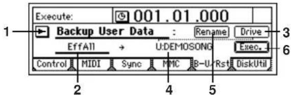
2. SourceEffNo.....(EffAll, Ins001...128, Mst001...032, Fin033...064)
Indicates the backup-source effect number. If you have selected the CD-R/RW drive, only "EffAll" can be selected here.
EffAll: All effect user data
Ins001...128: Insert effect user data
Mst001...032: Master effect user data
Fin033...064: Final effect user data
3. Drive ....[S, C, U]
Selects the backup-destination drive. (→p.103)
4. Destination..... (C:CD, U:EffctName)
Indicates the backup-destination drive and drive information (C:CD or U: filename).
Normally if you have set the "SourceEffNo" parameter to "EffAll," the file name will default to "backup-source song name .DFX", and if you have selected an individ-
ual effect, this file will be named "backup-source effect name .DFI (for an insert effect), .DFM (for a master effect), .DFF( for a final effect)".
When backing up to CD-R/RW, you must use a blank disc.
- Rename....
If you set "Drive" to "U:USB-DOS," you can change the name of the backup-destination file. (→p.103) You can input a filename of up to eight characters.
- Exec.(Execute)......
Executes the backup.
Backing up to CD-R/RW
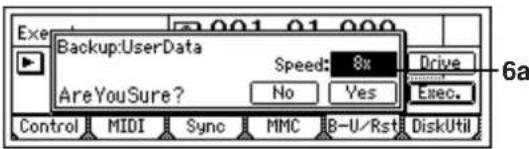
6a. Speed.....[1x, 2x, 4x, 6x, 8x]
When backing up to CD-R/RW, you can specify the writing speed. ( p.94) Only the writing speeds supported by your drive will be displayed. Press the [YES/OK] key to begin the backup.
Backing up to the USB drive
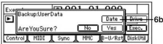
6b. Date ....
Input the date and time. Press the "Date" button to access the dialog box, and specify the date and time for the file. Move the cursor to the field you want to edit, and use the [VALUE] dial to specify the date and time.
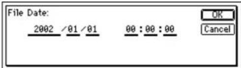
Press the [YES/OK] key to begin the backup.
The backup data cannot be saved if a file with the same name as the data to be backed up already exists on the USB drive. Either use a different filename, or delete the existing file from the USB drive.
B-U/RstType: "Restore"
This operation restores previously backed-up song or effect user data to the song drive of the hard disk.
- F r om a USB drive or CD to which you performed "Backup1Song," that song and effect user data will be restored.
- F r om a CD to which you performed "BackupAllSong," you can choose to restore one song or all songs. Effect user data will also be restored. - F r om a USB drive or CD to which you performed "BackupUserData," the effect user data will be restored.
When restoring one song or all songs, you can select whether effect user data will be restored. (→ "Restore: UserData")
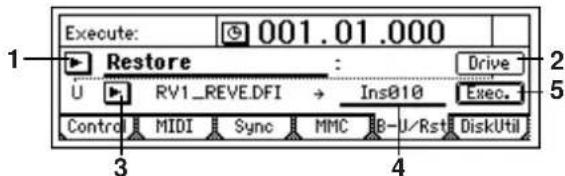
- Drive ....[S, C, U]
Selects the restore-source drive. (→p.103)
You can select either C:CD or U:DOS.
- Source ....
Selects the restore-source song or effect. Press the "button and make your selection in the dialog box.
When restoring from CD
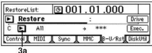
3a. BackUpFileList ....
Selects the file to restore.
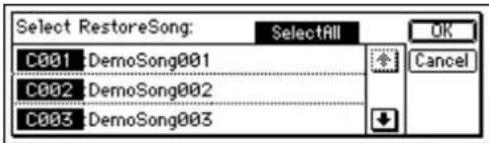
If you turn on the "SelectAll" button, all songs will be restored.
Press the [YES/OK] key to finalize your selection, or press the [NO/CANCEL] key to cancel your selection.
When restoring from the USB drive
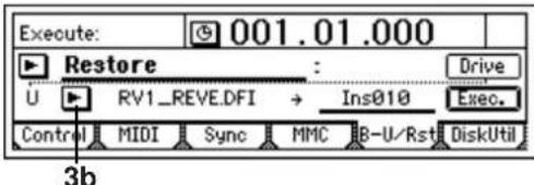
3b. BackUpFileList
Selects the file to restore.
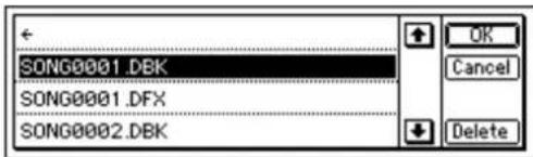
Folders are shown as [folder name] in the BackUpFileList screen. To see the contents of a folder, select [folder name] and press the [YES/OK] key.
To return, select “←” and press the [YES/OK] key.
Press the [YES/OK] key to finalize your selection, or press the [NO/CANCEL] key to cancel your selection.
It is not possible to restore all data at once.
3c. Delete
This lets you delete a file or folder.
4. Destination ....(001...100, \*\*\*, Effect, Ins001...128, Mst001...032, Fin033...064)
Selects the restore-destination song number or effect number. The data will be restored to the song number or effect number you select here. If you want to restore all songs, select "***".
5. Exec.(Execute)
Executes the restore operation.
The "Source" song(s) and user data will be restored to the "Destination" song(s) and user data.
When you restore one song, the "Source" song will be loaded into the "Destination" song number. Songs following the "Destination" number will be renumbered upward by one; they will not be overwritten.
When you restore all songs, all "Source" songs will be loaded after the songs that exist on the "Destination" song drive; they will not be overwritten.
When you restore effect user data, the "Source" user data will be overwritten onto the user data in the song drive.
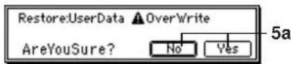
You can select whether effect user data of the same name as the song will also be restored.
Press the [YES/OK] key to execute the operation.
Yes: Effect user data will be restored, overwriting the (existing) effect user data.
No: Effect user data will not be restored.
note Effect user data is backed up automatically when you back up a song.
Note When restoring from the USB drive, the "Restore:UserData" dialog box will not appear if there is no effect user data of the same file name (the "song-name.DFX" file you are restoring).
Before any songs are restored, the restore-destination capacity will be checked, and the restore operation will not be executed if there is insufficient capacity.
DiskUtil: Disk drive management
Here you can format (initialize) the drive, check the drive, erase a CD-RW disc, connect to your computer via USB, and update the system software of the D1200.
When you format a drive or erase a CD-RW disc, all data on that drive or disc will be lost.
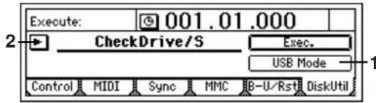
1. USB Mode
Allows your computer to communicate with the D1200. When you want to connect the D1200 to your computer, press this button to access the "USB Mode" screen, and the connected computer will recognize the USB drive.
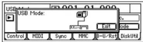
If you want to exit this screen while your computer is connected to the D1200 by a USB cable, you must perform an operation on your computer to "dismount" or "disconnect" the USB drive before you actually disconnect the USB cable. (→p.77)
2. SelOperation...... [CheckDrive/S, EraseCD-RW, Format/S, Format/U, FormatALL, LoadSystem/C, LoadSystem/U]
Selects the operation that will be performed on the drive.
Press the "button and make your selection from the list.
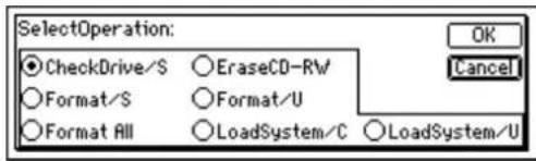
Details of each operation are explained separately, below.
"CheckDrive/S": Check the song drive
This operation detects errors on the song drive and repairs them. Perform this operation if "DiskBusy" error messages appear frequently. After executing this operation, you will still be able to use the song data if no major errors had occurred on the drive.
It is not possible to check the USB drive.
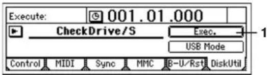
1. Exec.(Execute)......
Executes the check drive function.
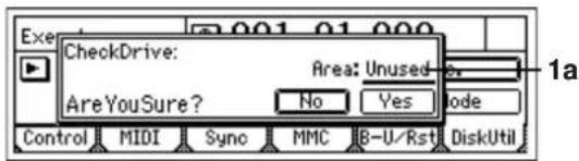
1a. Area......[Unused, Full, CurSng]
Specifies the area that will be checked.
Unused: Of the unused area, check and repair the first 2 GB that will be used next.
Full: Check and repair the entire area.
CurSong: Check and repair the area used by the currently selected song.
Press the [YES/OK] button to begin the drive check.
The Check Drive operation requires a certain amount of time. If "Area" is "Full": approximately 4 hours 30 minutes If "Area" is "Unused": approximately 25 minutes
If "DiskBusy" appears even after you perform the Check Drive operation, you will need to optimize the track data (→p.59, 111: [TRACK] "EditTrk" tab page "Optimize Track").
In a studio or similar location, vibration due to ultra-low frequencies may cause "DiskBusy" to occur. If this is the cause of the error message, you can solve the problem by moving the D1200 to a different location, rather than executing the Check Drive operation.
"EraseCD-RW": Erase a CD-RW disc
This operation erases all data that has been written to a CD-RW disc. When you erase a disc, you will once again be able to use the entire disc area as a blank disc.
When you execute "Erase CD-RW," all data on that disc will be lost.
You cannot execute "Erase CD-RW" on a disc other than a CD-RW.
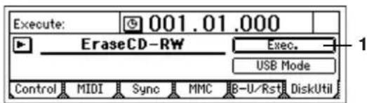
1. Exec.(Execute) ....
Executes erasure of the CD-RW disc.
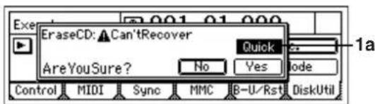
1a. Quick SW ....[On, Off]
Selects the erasure method for the CD-RW.
Quick On: A high-speed erase will be performed on the entire CD-RW disc. Since only the track information will be erased, the erasure will require less time. This will not affect writing.
Quick Off: The entire CD-RW disc will be erased completely. Use this setting if the disc is not recognized even after it was erased with the "Quick" turned on.
Press the [YES/OK] key to begin the erasure.
"Format/S": Format the song drive
This operation formats the song drive of the internal hard disk.
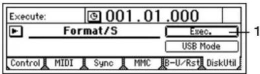
1. Exec.(Execute) ....
Executes formatting of the song drive.
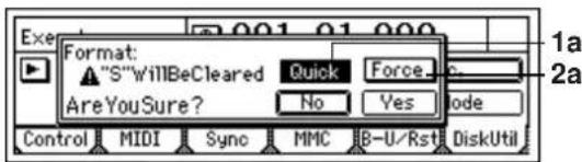
1a. Quick SW ......[On, Off]
Selects the format type.
Quick On: Select this if you want to erase the song data in a single operation. Since this will initialize only the management area, it will not require much time.
Quick Off: Select this if the "DiskError" message appears frequently.
A substantial amount of time will be required if you execute the format operation with "Quick" turned "Off." Song drive (38 GB): approximately 10 hours
2a. Force ....[On, Off]
Execute formatting even if the drive contains protected songs.
Force On: Forcibly execute formatting even if the drive contains a song protected by "Protect Song."
Force Off: If a song protected by "Protect Song" exists on the drive, the "Song Protect" message will appear when you attempt to execute, and the operation will be aborted.
Press the [YES/OK] key to begin the format operation.
"Format/U": DOS-format the USB drive
This operation DOS-formats the USB drive.
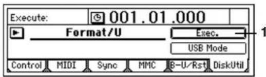
1. Exec.(Execute) ....
DOS-format the USB drive.
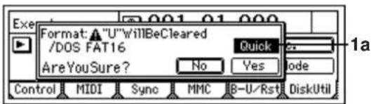
1a. Quick SW ....[On, Off]
Selects the type of format, press the [YES/OK] key to begin the format operation.
On: Select this if you want to erase all data saved on the entire USB drive. Since this will initialize only the management area, it will not require much time.
Off: Select this if the "DiskError" message appears frequently.
A substantial amount of time will be required if you execute the format operation with "Quick" turned "Off." USB drive (2 GB): approximately 35 minutes
"Format ALL": Format the entire hard disk
This operation formats both the song drive and the USB drive of the internal hard disk.
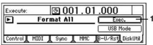
1. Exec.(Execute) ....
Executes formatting of the entire hard disk.
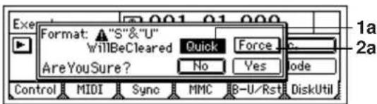
1a. Quick SW ....[On, Off]
Selects the type of format.
Quick On: Select this if you want to erase all data saved on the song drive and USB drive. Since this will initialize only the management area, it will not require much time.
Quick Off: Select this if the "DiskError" message appears frequently.
A substantial amount of time will be required if you execute the format operation with "Quick" turned "Off." 40 GB: approximately 10 hours 30 minutes
2a. Force ...... [On, Off]
Execute formatting even if the drive contains protected songs.
Force On: Forcibly execute formatting even if the drive contains a song protected by "Protect Song."
Force Off: If a song protected by "Protect Song" exists on the drive, the "Song Protect" message will appear when you attempt to execute, and the operation will be aborted.
Press the [YES/OK] key to begin the format operation.
"LoadSystem/C," "LoadSystem/U,": Update the D1200's system program
This operation loads the operating system from the CDRW-1 or USB drive, and rewrites the operating system program of the D1200. For details, refer to "Upgrading the system" ( p.81).
TRACK
Vtr1-6: Select virtual tracks 1-6
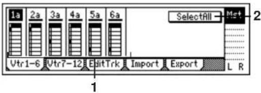
1. Select VirtualTrack......[1a...1h, ..., 6a...6h]
Selects the virtual track for each track "1" - "6." Each track has eight virtual tracks, "a" - "h." The virtual track you select here will be used for recording and playback.
![KORG D1200CD - Select VirtualTrack......[1a...1h, ..., 6a...6h] - 1](/content/2026/05/820878/images/04f29e08f59ed6177352a4030b40f1947a779a7fe9df6bf638e92e9468208990.jpg)
2. SelectAll ....[On, Off]
If you want to simultaneously select the same virtual track number for all tracks (1–12), turn this "On" and select the desired virtual track for any one of the tracks.
SelectAll On: All tracks will be set to the same virtual track number.
SelectAll Off: Virtual tracks can be selected individually for each track.
Vtr7-12: Select virtual tracks 7-12
For details, refer to "Vtr1-6."
In the case of a 24-bit song, this page cannot be selected.
1. Select VirtualTrack..... [7-8a...7-8h, ..., 11-12a...11-12h]
Select the virtual track for each pair of tracks.
2. SelectAll ....[On, Off]
EditTrk: Perform track editing operations
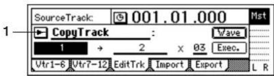
Only the currently selected V-track will be affected by these editing operations (→"Vtr 1-6," "Vtr7-12"). Virtual tracks that are not selected will not be affected. However, "CopyWholeTrack" and "SwapWholeTrack" are exceptions to this.
note The editing region (time) is specified by the times that are registered in the [IN/LOC1], [OUT/LOC2], [TO/LOC3], and [END/LOC4] keys ( p.33, 118).
IN time: the time location registered in the [IN/LOC1] key
OUT time: the time location registered in the [OUT/LOC2] key
TO time: the time location registered in the [TO/LOC3] key
END time: the time location registered in the [END/LOC4] key
You can either register these times to the appropriate keys beforehand, or set them using the "Wave" button of the [TRACK] "EditTrk" tab page.
Note After executing one of these operations, you can use Undo to return to the previous state if you are not satisfied with the result.
1. EditType.....[CopyTrack, InsertTrack, Erase Track, DeleteTrack, SwapTrack, ReverseTrack, OptimizeTrack, Exp/CompTrack, CopyWholeTrack, SwapWholeTrack, FadeTrack, NormalizeTrack]
Use the dial to select an editing operation.
Press the "button and choose from the list in the dialog box.
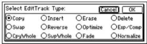
Each track editing operation is explained separately below.
EditType: "CopyTrack"
The audio data in the IN-OUT region of the copy-source track will be copied to the TO location of the copy-destination track, for the specified number of times.
You can use the clipboard to copy data to a track of a different song.
When you execute this operation, the destination track will be overwritten.
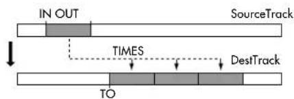
flowchart
graph TD
    A["IN OUT"] --> B["SourceTrack"]
    B --> C["TIMES"]
    C --> D["DestTrack"]
    D --> E["TO"]
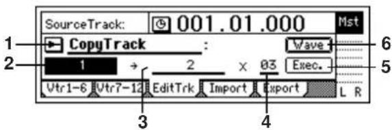
2. SourceTrack ..... [1...12, 1-2...11-12, 1-4...9-12, 1-6...7-12, 1-12, Clip#\*1]
Selects the copy-source track.
*1: "Clip#" can be selected only if the clipboard contains data. # indicates the number of tracks (1, 2, 4, 6, 12) in
the clipboard. You can use "Clip#" to copy data from a track of a different song.
note If you copy between songs of different bit rates, the data will be handled as 16-bit data at the copy-destination.
note For a 24-bit song, you will be able to select tracks 1–6.
- DestTrack ..... [1...12, 1-2...11-12, 1-4...9-12, 1-6, 7-12, 1-12, Clip#*1]
Select the copy-destination track.
*1: # indicates the number of tracks in the clipboard. You can use "Clip#" to copy data to a track of a different song.
note If you copy between songs of different bit rates, the data will be handled as 16-bit data at the copy-destination.
note For a 24-bit song, you will be able to select tracks 1–6.
- Times.....[1...99]
Specifies the number of times that the data will be copied.
- Exec.(Execute) ....
Executes the track editing operation.
- Wave....
Displays the waveform of the track audio.
Here you can set the editing region (IN, OUT, TO) more precisely.
This can be selected when the cursor is at "SourceTrack" or "DestTrack."
note Before you make settings here, it is a good idea to set the IN, OUT, and TO times to their approximately location
![KORG D1200CD - SourceTrack ..... [1...12, 1-2...11-12, 1-4...9-12, 1-6...7-12, 1-12, Clip#\*1] - 1](/content/2026/05/820878/images/2fab02db55ab7d766ed3e617240e0ab4b32b97b267a8a89fdaad65a622afe4ce.jpg)
Selects the track for which you want to view the waveform and specify a time location. Press the "▶" and select from the list.
6b. Zoom In/Out/Up/Down......
Adjusts the size of the waveform display and the play-back speed.
◆: Vertically expands the waveform display.
X: Vertically shrinks the waveform display.
◆: Horizontally expands the waveform display.
▶: Horizontally shrinks the waveform display.
6c. Locate ....[In, Out, To]
Specifies a counter location.
When you move the cursor to "Locate," the Scrub function will automatically be turned on, and you can turn the [VALUE] dial to specify a location while hearing only the sound of the track selected by "SelectTrack." When you press the [YES/OK] key, the current time will be overwritten to the location memory for that key (e.g., the [IN/LOC1] key). If you press the [NO/CANCEL] key, the setting will be cancelled. If you select Wave when the cursor is at "SourceTrack" the In and Out locations may be set. If you select Wave when the cursor is at
"DestTrack", then the To location may be set form this screen.
EditType: "InsertTrack"
Inserts blank space into the IN-OUT region of the insert-destination track.
When you execute this operation, track data that follows the inserted blank will be moved toward the end of the song.
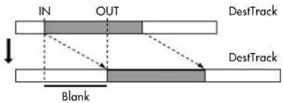
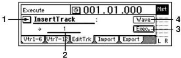
- DestTrack ..... [1...12, 1-2...11-12, 1-4...9-12, 1-6, 7-12, 1-12]
Selects the track into which blank space will be inserted.
note For a 24-bit song, you will be able to select tracks 1–6.
- Exec.(Execute) ....
Executes the track editing operation.
- Wave....
Displays the waveform of the track audio. Here you can set the editing locations (IN, OUT) more precisely. (→p.108: EditType: "CopyTrack")
EditType: "EraseTrack"
Erases the track data in the IN-OUT region of the erase-destination track.
When you execute this operation, the IN-OUT region will contain silence.
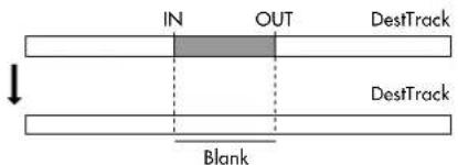
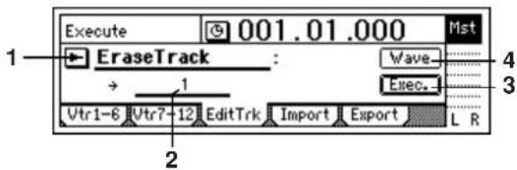
- DestTrack ..... [1...12, 1-2...11-12, 1-4...9-12, 1-6, 7-12, 1-12]
Selects the track in which data will be erased.
note For a 24-bit song, you will be able to select tracks 1–6.
- Exec.(Execute) ....
Executes the track editing operation.
4. Wave ....
Displays the waveform of the track audio. Here you can set the editing locations (IN, OUT) more precisely. (→p.108)
EditType: "DeleteTrack"
Deletes the track data in the IN-OUT region of the delete-destination track.
When you execute this operation, the data of the IN-OUT region will disappear, and the track data that follows the deleted region will move forward.
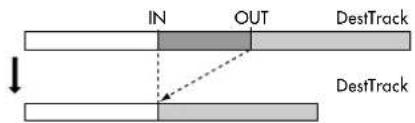
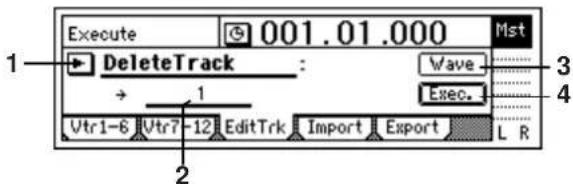
2. DestTrack...... [1...12, 1-2...11-12, 1-4...9-12, 1-6, 7-12, 1-12]
Selects the track from which data will be deleted.
note For a 24-bit song, you will be able to select tracks 1–6.
3. Wave ....
Displays the waveform of the track audio. Here you can set the editing locations (IN, OUT) more precisely. (→p.108)
4. Exec.(Execute)....
Executes the track editing operation.
EditType: "SwapTrack"
Swaps (exchanges) the IN-OUT region of the swap-source track with the IN-OUT region of the swap-destination track. When you execute this operation, the data of the IN-OUT regions of the selected tracks will be exchanged.
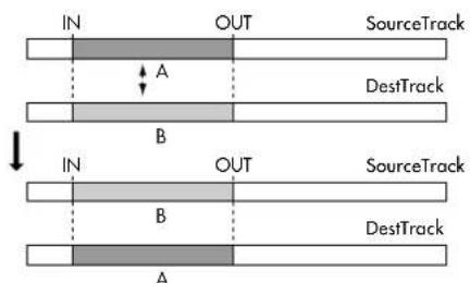
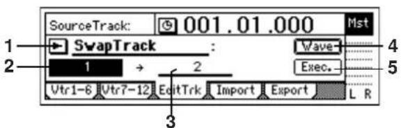
2. SourceTrack ..... [1...12, 1-2...11-12, 1-4...9-12, 1-6, 7-12, 1-12]
Selects the swap-source track.
Note For a 24-bit song, you will be able to select tracks 1–6.
3. DestTrack..... [1...12, 1-2...11-12, 1-4...9-12, 1-6, 7-12, 1-12]
Selects the swap-destination track.
note For a 24-bit song, you will be able to select tracks 1–6.
4. Wave ....
Displays the waveform of the track audio. Here you can set the editing locations (IN, OUT) more precisely. (→p.108)
5. Exec.(Execute) ....
Executes the track editing operation.
EditType: "ReverseTrack"
Copies the IN-OUT region of the reverse-source track data to the TO location of the reverse-destination track, in reverse (end-for-end). You can specify the number of times that the data will be copied.
When you execute this operation, the copied region will be reversed, and will play backward when you play back.
note This operation will overwrite the data in the destination region.
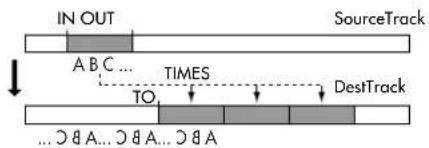
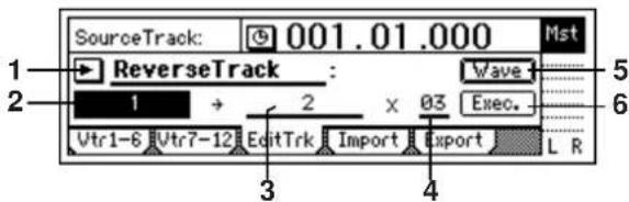
2. SourceTrack ..... [1...12, 1-2...11-12, 1-4...9-12, 1-6, 7-12, 1-12]
Selects the reverse-source track.
note For a 24-bit song, you will be able to select tracks 1–6.
3. DestTrack..... [1...12, 1-2...11-12, 1-4...9-12, 1-6, 7-12, 1-12]
Selects the reverse-destination track.
note For a 24-bit song, you will be able to select tracks 1–6.
4. Times.....[1...99]
Specifies the number of times that the reversed data will be copied.
5. Wave ....
Displays the waveform of the track audio. Here you can set the editing locations (IN, OUT) more precisely. (→p.108)
6. Exec.(Execute) ....
Executes the track editing operation.
EditType: "OptimizeTrack"
Optimizes the track data in the IN-OUT region of the optimize-destination track.
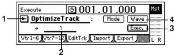
2. DestTrack.... [1...12, 1-2...11-12, 1-4...9-12, 1-6, 7-12, 1-12]
Selects the track that will be optimized.
note For a 24-bit song, you will be able to select tracks 1–6.
3. Mode...... [Normal, Erase Silence, Erase Punch Noise]
Selects the type of optimization that will be performed.
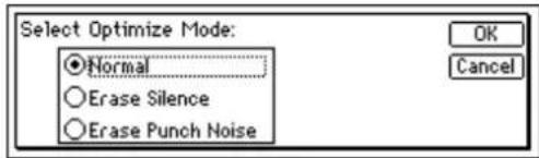
Normal: This operation re-creates the audio events in the IN–OUT region to prevent DiskBusy errors from occurring. If there are no gaps between one audio event and the next, or if the gap is small, the data will be combined into a single event. If there are extended gaps between audio events, the data will be re-created in a way that avoids wasting space.
Note By setting the IN-OUT region to the beginning and end of the song, and executing the Optimize Track operation, you can re-create the data in a form that will be ideal for hard disk access.
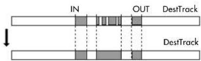
Erase silence: In an extended recording that contains significant amounts of silence, this operation erases the silent regions, and divides the areas containing sound into separate events.
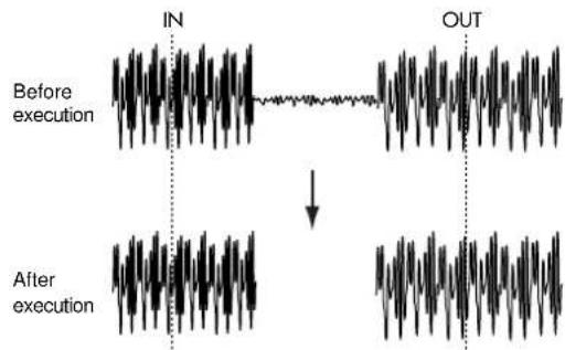
Note Levels lower than -36 dB will be considered as silence. Erase Punch Noise: This operation minimizes the "blip" of noise that occurs at junctions between recording (e.g., punch-in/out) and track editing. Set the IN and OUT times slightly before and after the click noise occurs.
![KORG D1200CD - Mode...... [Normal, Erase Silence, Erase Punch Noise] - 4](/content/2026/05/820878/images/d72fb14ed43c04ea70ac6a06235bfebee84b73d8f22205c898706ae63c3eb90d.jpg)
line
| Time Point | Before execution | After execution | | ---------- | ---------------- | --------------- | | IN | High | Low | | OUT | High | Low |4. Wave....
Displays the waveform of the track audio. Here you can set the editing locations (IN, OUT) more precisely. (→p.108)
5. Exec.(Execute) ....
Executes the track editing operation.
EditType: "Exp/CompTrack"
Expands or compresses the track data from the IN-OUT region of the source track so that it will fit in the TO-END region of the destination track, and copies it to the destination track the specified number of times.
This operation overwrites the data in the destination track.
There is a limit to the ratio of expansion or compression that can occur. If the IN-OUT region and the TO-END region are dramatically different in length, an error will occur when you attempt to execute. You should keep the ratio of the TO-END time and IN-OUT time within a range of 50–200%.
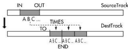
flowchart
graph TD
    IN["IN"] --> A["A"]
    OUT["OUT"] --> B["B"]
    SourceTrack["SourceTrack"] --> T1["TIMES"]
    DestTrack["DestTrack"] --> T2["TIMES"]
    T1 --> T3["TO"]
    T2 --> T4["END"]
    T3 --> T5["ABC ... ABC ... ABC ..."]
    T4 --> T6["ABC ... ABC ... ABC ..."]
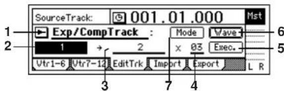
2. SourceTrack ....[1...12, 1-2...11-12]
Selects the expansion/compression-source track.
Note For a 24-bit song, you will be able to select tracks 1–6.
3. DestTrack ....[1...12, 1-2...11-12]
Selects the expansion/compression-destination track.
note For a 24-bit song, you will be able to select tracks 1–6.
4. Times.....[1...99]
Specifies the number of times that the data will be copied.
5. Exec.(Execute) ....
Executes the track editing operation.
6. Wave ....
Displays the waveform of the track audio. Here you can set the editing locations (IN, OUT, TO, END) more precisely. (→p.108)
7. Mode ....
Selects the way in which expansion/compression will be processed.
Press the "Mode" button to open the following dialog box.
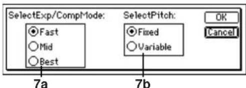
Press the [YES/OK] key to apply the selected processing method.
Your selections will be discarded if you press the [NO/CANCEL] key.
7a. SelectExp/CompMode......[Fast, Mid, Best]
Selects the conversion mode for expansion/compression.
Fast: Processing will be performed as quickly as possible.
Mid: Mid-way between "Fast" and "Best"
Best: Audio quality will be maintained as high as possible.
However, this setting has no effect if "SelectPitch" is set to "Variable."
7b. SelectPitch ....[Fixed, Variable]
Selects whether the playback pitch will be affected by the expansion/compression command.
Fixed: The pitch will not change
Variable: The pitch will change
EditType: "CopyWholeTrack"
Copies the entire copy-source track (the currently selected virtual track) from beginning to end, to the specified virtual track of the copy-destination track.
This operation overwrites the data of the destination track.
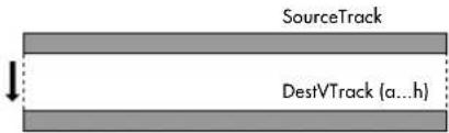
flowchart
graph TD
    A["SourceTrack"] --> B["DestVTrack (a...h)"]
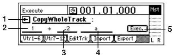
2. SourceTrack ..... [1...12, 1-2...11-12, 1-4...9-12, 1-6, 7-12, 1-12]
Selects the copy-source track.
note For a 24-bit song, you will be able to select tracks 1–6.
3. DestTrack..... [1...12, 1-2...11-12, 1-4...9-12, 1-6, 7-12, 1-12]
Selects the copy-destination track.
note For a 24-bit song, you will be able to select tracks 1–6.
4. DestVTrack..... [a..h]
Selects the virtual track of the copy-destination track ("DestTrack").
5. Exec.(Execute) ....
Executes the track editing operation.
EditType: "SwapWholeTrack"
Swaps (exchanges) the entire swap-source track (the currently selected virtual track) with the specified virtual track of the swap-destination track.
Use this when you want to rearrange the order of the recorded tracks. For example when you have finished a song, you could use this operation to place the final data for all tracks in virtual track "a."
When you execute this operation, the track data of the "SourceTrack" and "DestTrack" will be exchanged.
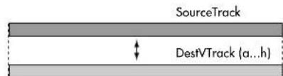
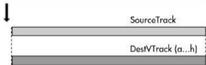
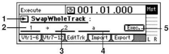
2. SourceTrack ..... [1...12, 1-2...11-12, 1-4...9-12, 1-6, 7-12, 1-12]
Selects the swap-source track.
note For a 24-bit song, you will be able to select tracks 1–6.
3. DestTrack..... [1...12, 1-2...11-12, 1-4...9-12, 1-6, 7-12, 1-12]
Selects the swap-destination track.
note For a 24-bit song, you will be able to select tracks 1–6.
4. DestVTrack.....[a..h]
Selects the virtual track of the swap-destination track ("DestTrack") whose data will be exchanged.
5. Exec.(Execute) ....
Executes the track editing operation.
EditType: "FadeTrack"
Fades-in or fades-out the track data in the IN-OUT region of the destination track. The level of the audio data in the IN-OUT region will fade smoothly toward the OUT time.
This operation will overwrite the destination track.
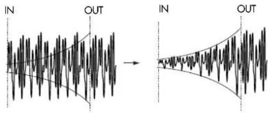
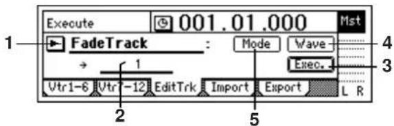
- DestTrack..... [1...12, 1-2...11-12, 1-4...9-12, 1-6, 7-12, 1-12]
Selects the destination track.
note For a 24-bit song, you will be able to select tracks 1–6.
- Exec.(Execute) ......
Executes the track editing operation.
- Wave....
Displays the waveform of the track audio. Here you can set the editing locations (IN, OUT) more precisely. (→p.108)
- MODE......
Selects the fade curve for the fade-in or fade-out.
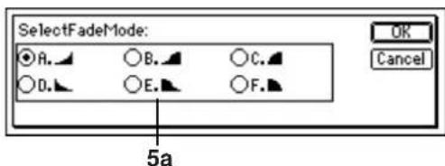
5a. SelectFadeMode..... [A...F]
A: This curve is suitable for a conventional fade-in.
B: This curve is suitable for creating a cross-fade by performing a fade-in and fade-out on two tracks at the same time location.
C: This curve inverts curve A, lengthening the time that the sound is heard.
D: Fade-out using curve A.
E: Fade-out using curve B.
F: Fade-out using curve C.
Press the [YES/OK] key to confirm the fade mode you selected.
Press the [NO/CANCEL] key to cancel your selection.
EditType: "NormalizeTrack"
If an audio source was recorded at an inappropriately low level, you can use this operation to raise the level of the data in the specified region (IN-OUT) to the maximum level possible without clipping.
This operation will overwrite the data of the destination track.
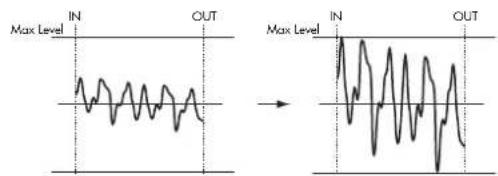
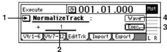
- DestTrack ....[1...12, 1-2...11-12]
Selects the track in which the audio data will be normalized.
note For a 24-bit song, you will be able to select tracks 1–6.
- Exec.(Execute) ....
Executes the track editing operation.
- Wave.....
Displays the waveform of the track audio. Here you can set the editing locations (IN, OUT) more precisely. (→p.108)
Import: Import WAV files
A WAV file that was saved on a CD-ROM/R/RW or on the USB drive can be pasted into a track of the D1200. You can also use the clipboard to paste the WAV file at a location other than the beginning of the song. The D1200 lets you import WAV files of the following formats.
Sampling frequency: 44.1 kHz
Bit depth: 8-bit, 16-bit, 24-bit
Number of channels: 1 (monaural), 2 (stereo)
Note If you want to import a WAV file from your computer, use a USB cable to connect your computer to the D1200, and save the WAV file on the D1200's USB drive. Then continue with the procedure described below.
The D1200 can import WAV files from an ISO9660 level 1 format CD-ROM, CD-R, or CD-RW.
Executing this operation will overwrite the import-destination track.
Importing or exporting a WAV file will require a certain amount of time. The following table shows some examples of the time required to import or export a five-minute 16-bit 44.1 kHz monaural WAV file.
| CD | USB drive | ||
| Import | 1 minute 40 seconds | 1 minute 20 seconds | |
| Export | 2x | 6 minutes 10 seconds | 1 minute 20 seconds |
| 4x | 5 minutes 20 seconds | ||
| 8x | 4 minutes 10 seconds | ||
* The processing time will also depend on the format of the WAV file and on the type of disc you are using.
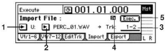
1. DriveList ....[S, C, U]
Selects the drive. For details on the drive, refer to "Drive" (→p.103).
2. WavFileList.
Selects the WAV file.
Press the [YES/OK] key to confirm your selection. If you press the [NO/CANCEL] key, your selection will be cancelled.
![[PERC_44K] [DL_44K]](/content/2026/05/820878/images/9824239da47d3eb136e40ce84f32e68113f6e31d9b673f21d05f405381f19ae9.jpg)
In the WavFileList screen, the folder is indicated as [(folder name)].
To view the contents of a folder
Select [(folder name)] and press the [YES/OK] key.
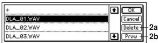
To return
Select "←" and press the [YES/OK] key.
Pressing the [YES/OK] key will confirm your selection, and pressing the [NO/CANCEL] key will cancel your selection.
2a. Delete....
You can delete a WAV file or folder from the USB drive. Select the WAV file or folder that you want to delete, and press the "Delete" button to delete it.
2b. Prvw ....
You can preview (audition) the first two seconds of the selected WAV file.
If you select a WAV file of an unsupported format, the following error message will appear.
SAMPLE RATE NOT 44.1k: This will appear if the WAV file has a sampling rate other than 44.1 kHz.
SAMPLE BIT NOT FIT: This will appear if the WAV file has a bit depth of other than 8-bit, 16-bit, or 24-bit.
ILLEGAL WAV DATA: This will appear if the WAV file is unsupported for a reason other than the above.
3. DestTrack......[1...12, 1-2...11-12, clip#]
Selects the destination track into which the WAV file will be imported.
CLIP# will be 1 if the selected WAV file is monaural, or 2 if it is stereo.
4. FileType M.S,
Indicates whether the selected WAV file is monaural or stereo.
M: The selected WAV file is monaural.
54: The selected WAV file is stereo.
5. Exec.(Execute) ....
Executes the WAV file import operation.
Export: Export a WAV file
The audio track data you copied to the clipboard can be saved as a WAV file on a CD-R/RW disc or the USB drive. The D1200 can export WAV files in the following formats.
Sampling frequency: 44.1 kHz
Bit depth: 16-bit, 24-bit
Number of channels: 1 (monaural), 2 (stereo)
note When you export a WAV file to a CD-R/RW, the data will be in ISO9660 level 1 format.
Note After exporting a WAV file to the USB drive, you can connect a USB cable and save the WAV file on your computer.
When you export 24-bit clipboard data, you can select whether it will be exported as 16-bit data or as 24-bit data. If you select 16-bit export, you can specify whether dithering will be performed on the data.
note Dithering will make the quantization noise less noticeable.
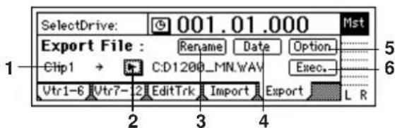
1. Clip#
Indicates the status of the clipboard.
# indicates the number of tracks in the clipboard.
2. DriveList.....[S, C, U]
Selects the drive. For details on the drive, refer to "Drive" (→p.103).
3. Rename ....
Press the "Rename" button to access the dialog box, and assign a name to the WAV file. You can assign a name of up to six characters to the WAV file.
note The seventh and eighth characters will be assigned automatically as follows, according to the number of tracks you are exporting.
MN: When exporting one track (monaural file)
ST: When exporting two tracks (stereo file)
01: When exporting four tracks or more, a number of 01–12 will be assigned automatically. (Each file will be monaural.)
4. Date ....
Lets you input the date and time of the exported WAV file. Press the "Date" button to access the dialog box, and specify the date and time of the WAV file. Move the
cursor to the date or time field you want to edit, and turn the [VALUE] dial to set the date and time.
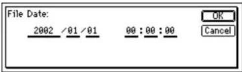
Press the [YES/OK] key to apply the specified date and time, or press the [NO/CANCEL] key to discard the changes you made.
Note The D1200 does not support the "time differential with Greenwich Mean Time (GMT)" setting. Depending on your computer or operating system, the creation date and time of the WAV file may not be displayed correctly.
- Option......
Specifies how the WAV file will be exported to CD-R/RW.
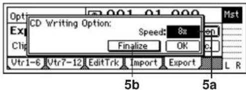
5a. CD WritingSpeed .....[1x, 2x, 4x, 6x, 8x]
If exporting to CD-R/RW, you can specify the writing speed. (→p.94)
Only the writing speeds supported by the drive and media you are using will be displayed.
5b. Finalize.....[On, Off]
You may export additional WAV files to a CD-R/RW that already contains data, but if this is the last addition you want to make to this disc, you can turn this field On. Some drives such as early CD-ROM drives cannot read a disc unless it has been finalized.
If the CD-R/RW disc has no more space for additional data to be written, it will be finalized automatically.
- Exec.(Execute) ....
Executes the WAV file export operation.
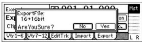
6a. Export Size ....[16bit, 24bit]
Selectable only if the clipboard contains 24-bit data
You can select whether the 24-bit data that was copied to the clipboard will be exported as a 16-bit WAV file or as a 24-bit WAV file.
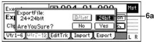
6b. Dither SW ...... [On, Off]
Selectable only when exporting 24-bit → 16-bit
If 24-bit data from the clipboard is being exported as a 16-bit WAV file, you can specify whether dithering will be performed.
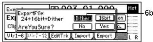
DigiIn On: Dithering will be performed on the data to make quantization noise less noticeable.
DigiIn Off: Dithering will not be performed.
SONG
SelSong: Select a song
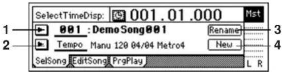
1. SongNumber ....[001...100]
Selects the song.
The display shows the song number and song name.
A "24" symbol is displayed if you have selected a 24-bit song, and a "symbol is displayed if the song is protected.
Press the "button and select a song from the list.
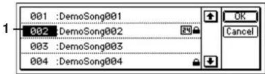
note You can also select a song by holding down the [STOP] key and pressing the [FF] key or [REW] key.
2. Select DispParameter ..... [Tempo, Mark, Scene]
Displays the current tempo, mark, or scene.
Press the "button and select what will be displayed.
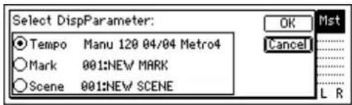
Tempo: The tempo source, tempo, time signature, and rhythm of the song will be displayed.
Tempo Manu 120 04/04 Metro
Mark: The number and name of the Mark at or before the current time location of the song will be displayed.
Mark 001: MarkName0001
Scene: The number and name of the Scene at the current time location of the song will be displayed.
Scene 001: Intro
3. Rename....
Select the "Rename" button and press the [ENTER] key to open the dialog box and edit the song name. You can input a song name of up to sixteen characters. (→p.31)
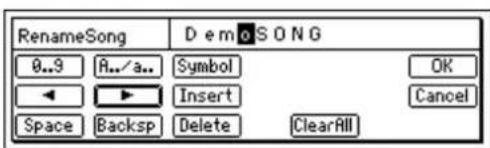
4. New......
Creates a new song following the last song.
Press the "New" button to open the dialog box.
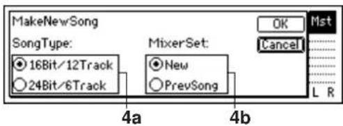
Make the desired settings for "SongType" and "MixerSet," select the [YES/OK] key, and press the [ENTER] key to create the new song. If you want to cancel the operation, press the [NO/CANCEL] key.
4a. SongType..... [16Bit/12Track, 24Bit/6Track]
16Bit/12Track: Create a song for 16-bit recording and playback. You can use tracks 1–12. A maximum of four tracks can be recorded simultaneously.
24Bit/6Track: Create a song for 24-bit recording and playback. You can use tracks 1–6. Tracks 7–12 will not be available. A maximum of four tracks can be recorded simultaneously.
note If you copy audio data from a 16-bit song, that data will be handled as 16-bit data. (→ p.108)
The "SongType" (Bit/Track) setting can be changed only when you are creating a new song.
4b. MixerSet...... [New, PrevSong]
Select the mixer settings that will be used for the new song.
New: Use the default settings.
PrevSong: Use the mixer settings of the currently selected song.
EditSong: Perform song edit operations
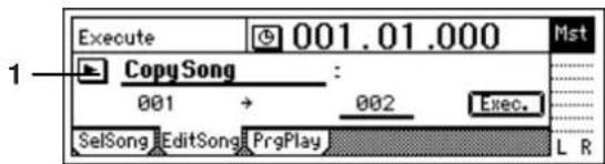
Note These editing operations apply to the currently selected song.
The Undo command is not available for these operations.
1. EditType...... [CopySong, MoveSong, DeleteSong, ProtectSong]
Press the "button to access the dialog box, and select the editing command you want to use.
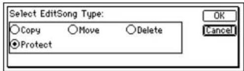
Each type of song editing command is explained separately, below.
EditType: "CopySong"
Copies the selected song to the song number you specify.
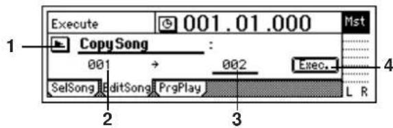
2. SourceSong ..... (001...100)
Indicates the copy-source song number. If you want to change this, select a different song in the [SONG] "SelSong" tab page.
3. DestSong ....[001...100]
Selects the copy-destination song number. Here you can select a number in the range from "001" to "existing song number + 1".
4. Exec.(Execute) ....
Executes the copy.
When you execute, the song will be copied to the copydestination song number ("DestSong"). Even if "Dest-Song" is an existing song number, it will be inserted, not be overwritten. Subsequent songs will be renumbered upward by one.
Undo is not available for this operation.
EditType: "MoveSong"
Moves the selected song to a different song number.
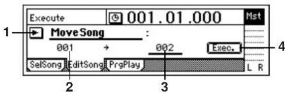
2. SourceSong ..... (001...100)
Indicates the move-source song number. If you want to change this, select a different song in the [SONG] "SelSong" tab page.
3. DestSong ....[001...100]
Selects the move-destination song number. You can select a number in a range from "001" to "existing song number."
4. Exec.(Execute) ....
Executes the Move Song operation. If the move-destination ("DestSong") number you selected is higher than the move-source number ("SourceSong"), songs earlier than the "DestSong" number will be moved forward by one (or backward by one if the move-destination number is lower than the move-source number). They will not be overwritten.
Undo is not available for this operation.
EditType: "DeleteSong"
Deletes the selected song.
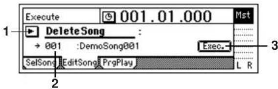
2. DestSong ..... (001...100)
Indicates the number and name of the song that will be deleted. If you want to change this, select a different song in the [SONG] "SelSong" tab page.
3. Exec.(Execute) ....
Executes the deletion.
When you execute this operation, the "DestSong" song will be deleted, and subsequent songs will be renumbered downward by one.
Undo is not available for this operation.
EditType: "ProtectSong"
Protects the selected song so that it cannot be written or deleted. When you have completed a song, you can protect it against accidental change or deletion.
Turning the Protect setting on will disable all erasure or writing operations such as recording, track editing, or registering scenes.
note If the Protect setting is on, the settings of the song will also be protected. You will be able to adjust the faders or EQ, but will not be able to store your changes.
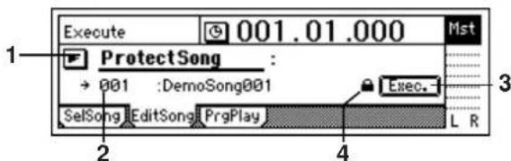
2. DestSong ..... (001...100)
Indicates the number and name of the song that will be protected. If you want to change this, select a different song in the [SONG] "SelSong" tab page.
3. Exec.(Execute) ....
Executes the protect operation.
Each time you execute, the protect setting will be switched on/off.
4. Protect On/Off Mark..... [On, Off]
If protect is "On," the lock symbol "will be displayed. If protect is "Off," the lock symbol will not be displayed. Press the "Exec" button to switch this on/off.
PrgPlay: Program playback of songs
By arranging songs in the program play list, you can automatically play them in any order.
For details on the settings and procedure, refer to p.56.
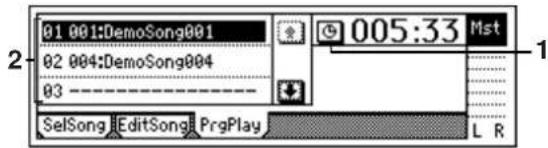
1. Select TimeDisp Type ...... [Abs-Song, Abs-Total]
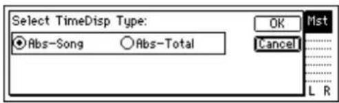
Selects the counter display type.
Abs-Song: Display the elapsed time for one song.
Abs–Total: Display the elapsed time for the entire program.
To confirm the setting you have selected, press the [YES/OK] key. To cancel your selection, press the [NO/CANCEL] key.
2. ProgramPlay List..... [01...99]
Arrange songs in this list to specify the playback order. The songs will play back in the listed order from top to bottom.
Each line of the list indicates (from the left) the playback order, song number, and song name.
If a song in the list cannot be found, it will be skipped and the next song in the play list will be played.
IN/LOC1, OUT/LOC2, TO/LOC3, END/LOC4
Locations within a song that you register to the [IN/LOC1], [OUT/LOC2], [TO/LOC3], and [END/LOC4] keys are used by the following functions.
- Locate point (move to the registered time when you press a key)
- Loop playback in/out point
• Auto-punch recording in/out points
• T rack editing points - In-out playback
When you hold down the [IN/LOC1] key and press the [OUT/LOC2] key, this function plays from the IN time (registered in the [IN/LOC1] key) to the OUT time (registered to the [OUT/LOC2] key). This is useful when you want to play back the IN-OUT region of the song to verify the contents of the region.
Locate functions
IN/LOC1
The time location that you register for the [IN/LOC1]
key is used for the following purposes.
- Locate point 1
- Punch-in time for auto-punch recording
- Playback start time for loop playback
- Playback start time for in-out playback
• The following times for track editing operations
Starting time of the copy-source for "Copy Track" Starting time of the inserted silence for "Insert Track" Starting time of the erased region for "Erase Track" Starting time of the deleted region for "Delete Track" Starting time of the swap-source and swap-destination for "Swap Track"
Starting time of the data to be reversed for "Reverse Track"
Starting time of the data to be expanded/compressed for "Exp/Comp Track"
Starting time for "Optimize Track"
Starting time for "Fade Track"
Starting time for "Normalize Track"
OUT/LOC2
The time location that you register for the [OUT/LOC2] key is used for the following purposes.
- Locate point 2
- Punch-out time for auto-punch recording
- Playback end time for loop playback
- Playback end time for in-out playback
- The following times for track editing operations Ending time of the copy-source for "Copy Track" Ending time of the inserted silence for "Insert Track" Ending time of the erased region for "Erase Track" Ending time of the deleted region for "Delete Track" Ending time of the swap-source and swap-destination for "Swap Track"
Ending time of the data to be reversed for "Reverse Track"
Ending time of the data to be expanded/compressed for "Exp/Comp Track"
Ending time for "Optimize Track"
Ending time for "Fade Track"
Ending time for "Normalize Track"
TO/LOC3
The time location that you register for the [TO/LOC3] key is used for the following purposes.
- Locate point 3
- The following times for track editing operations Starting time of the copy-destination for "Copy Track"
Starting time of the reverse-copy destination for "Reverse Track"
Starting time + copy-destination time of the expanded/compressed data for "Exp/Comp Track"
END/LOC4
The time location that you register for the [END/LOC4] key is used for the following purposes.
- Locate point 4
- The following time for a track editing operation Ending time of the expanded/compressed data for "Exp/Comp Track"
MARK
You can register a location as a Mark, and move to that registered location. You can also assign a name to each mark, and use marks to designate sections of a song. When you use Disc At Once to write an audio CD, the marks you registered will be written to the CD as track markers to indicate where each song on the disc begins.
note Up to 100 marks can be registered in a song.
Mark: Edit marks
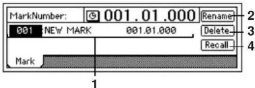
- MarkNumber ....[001...100]
Selects the mark number. The name and time of the mark are displayed beside the mark number.
note Mark numbers are updated automatically in the order of the registered time.
2. Rename ....
Edits the name of the mark.
Select the mark whose name you want to edit, select the "Rename" button, press the [ENTER] key to open the dialog box, and edit the name. You can input a name of up to sixteen characters. (→p.31)
- Delete....
Deletes a mark.
Undo is not available when you delete a mark.
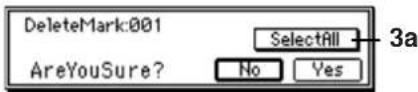
3a. SelectAll..... [On, Off]
Selects all marks for deletion.
SelectAll On: All marks will be deleted. The mark number will be indicated as “**”.
SelectAll Off: The mark selected by "MarkNumber" will be deleted.
Press the [YES/OK] key to delete the specified mark(s).
- Recall ....
Recalls the mark selected by "MarkNumber" and moves the current time to that location.
SCENE
Mixer settings can be registered as a Scene in a specific location, and recalled automatically as playback progresses. You can also register frequently-used settings as a scene, and recall them for use whenever necessary.
Up to 100 scenes can be registered in a song.
note The following mixer parameters can be registered in a scene.
MixerChannel
EQ, Effect Send 1 and 2, Aux Send, Pan/Balance, Channel Fader, and Pair On/Off
InsertEffect (only if Assign is "Trk")
Effect Type, Insert To, Effect Number
MasterEffect
Effect Number, Effect Return
FinalEffect
Effect Number
ReadDel: Switch scene playback on/off, and edit scenes
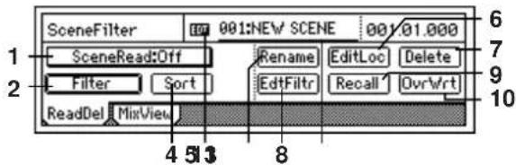
1. SceneRead.....[On, Off]
Switch scene playback on/off.
SceneRead:On On: Scene playback will be enabled. When playback reaches the location at which a scene is registered, that scene will be recalled, and the mixer settings will change automatically.
If this is "On," the [SCENE] key will light.
SceneRead:Off Off: Scene playback will be disabled. You will be able to recall scenes as general-purpose settings whenever you want, regardless of the time. (→p.40: "3-3. Recalling a scene")
2. Filter......
You can use the scene filter to prevent specific mixer parameters from being changed by a scene.
When you register a scene, the filter settings you make here will be registered for that scene.
When you play back a scene, these filter settings will apply to all scenes.
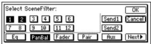
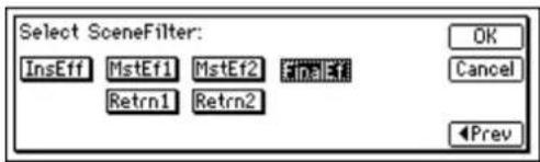
On: Filtering will be applied to that channel/parameter, and the corresponding scene settings will be disabled.
Off: Filtering will be off, and the scene settings will be valid.
3. SceneNumber ....[001...100]
The mixer settings of this scene will be recalled to the current location.
You can also use this field to recall a scene whose name you want to edit or whose location you want to change. The time at which the scene is registered is indicated at the right of this area.
If "SceneRead" is "Off," you can use this area to select a desired scene. If "SceneRead" is "On," the scene for the current location will be selected, and cannot be changed manually.
4. Sort....
Sorts the scenes by their order of appearance in the song, from beginning to end.
Normally, scenes are arranged in the order in which they were registered. However you can sort them so that they will appear in the order of the registered times.
Undo is not available for this Sort operation.
5. Rename ....
Edits the name of a scene.
Use "SceneNumber" to recall the scene whose name you want to edit, press the "Rename" button to open the dialog box, and edit the name. You can input a name of up to sixteen characters. (→p.31)
If you set "Select DispParameter" to "Scene" in the [SONG] "SelSong" tab page, the scene name will be displayed in that page. (→p.116)
6. EditLoc ....
Edits the registered time location of the scene.
Use "SceneNumber" to recall the scene whose location you want to change.
Press the "EditLoc" button to open the dialog box, and edit the location of the scene.
Move the cursor to the unit of time you want to change, and use the [VALUE] dial to edit the time.
Press the [YES/OK] key to confirm the change, or press the [NO/CANCEL] key to cancel the change.
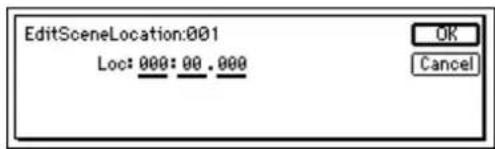
7. Delete......
Deletes a scene or all scenes.

Undo is not available for this Delete operation.
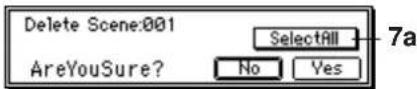
7a. SelectAll.....[On, Off]
All scenes will be selected for deletion.
SelectAll On: All scenes will be selected for deletion.
The scene number will be indicated as “***”.
SelectAll Off: The single scene number selected in
"SceneNumber" will be selected for deletion.
8. EditFilter ......
You can view and edit the "Filter" settings that are registered in each scene.

Even when you store a scene with filtering applied, the parameters at that time are actually saved. By changing the filter settings in this page, you can recover the state of those parameters at the time the scene was stored.
9. Recall ....
Recalls the settings that are registered in a scene. If you recall a scene and edit the EQ etc. and then press the "Recall" button to recall the scene, the state prior to your editing (i.e., the mixer settings registered in the scene) will be recalled.
10.OvrWrt......
Overwrites the current mixer settings onto the selected scene number. Use this when you want to make fine adjustments to the scene or replace it with a different scene.
11. EDIT......
This indicator will appear if the parameters of the scene have been edited from the state in which they were registered.
MixView: Viewing pan and fader scene data
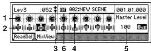
1. Pan/Balance... (Pan1...Pan6, Bal7-8...Bal11-12)
Displays the currently selected pan and balance settings. When you select an icon, the channel number and parameter value will appear in the upper left.
2. Level..... (Lev1...Lev6, Lev7-8...Lev11-12)
Displays the currently selected channel fader settings. When you select an icon, the channel number and parameter value will appear in the upper left.
If the level is unity gain, the display will indicate "l"
3. Pan/fader guide ....[ ↓↓+‡↑↑→++‡+••]
Displays a symbol to indicate the difference between the actual fader or pan position and the value that is registered in the scene.
When you recall a scene, the current position of the fader may differ from the value registered in the scene. When you select the parameter for which you want to resolve this discrepancy, a symbol will be displayed to indicate the difference between the internal value and the fader position.
Fader
↓: The fader is more than 51 steps above the internal value.
↓: The fader is 21–50 steps above the internal value.
: The fader is 1–20 steps above the internal value.
: The fader matches the internal value.
↑: The fader is 1–20 steps below the internal value.
↑: The fader is 21–50 steps below the internal value.
↑: The fader is more than 51 steps below the internal value.
Pan
→: The pan knob is more than 51 steps to the left of the internal value.
→: The pan knob is 21–50 steps to the left of the internal value.
◆: The fader knob is 1–20 steps to the left of the internal value.
: The fader knob matches the internal value.
◆: The fader knob is 1–20 steps to the right of the internal value.
+: The fader knob is 21–50 steps to the right of the internal value.
←: The fader knob is more than 51 steps to the right of the internal value.
4. SceneNumber ....[001...100]
Recalls the mixer settings of the scene to the current time location. (→p.120)
5. Master Level..... [000...127]
Indicates the level of the master fader.
If the level is at unity gain, this will indicate "0dB".
6. EDIT......
This indicator will appear if the parameters of the currently-recalled scene have been edited. You can register your changes by using "OvrWrt" in the [SCENE] "Read-Del" tab page.
AUTO PUNCH
AtPunch: Settings for auto punch-in/out recording
Auto punch-in/out recording is a function that automatically starts recording (punch-in) and stops recording (punch-out) at the locations you specify ahead of time.
If "AutoPunch" is "On" when you record, punch-in/out recording will be performed.
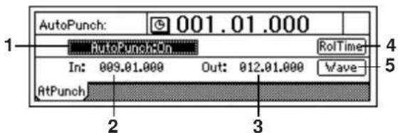
Switches the auto punch-in/out recording function on/off.
AutoPunch:On On: Auto punch recording will be used when you record. If this is "On," the [AUTO PUNCH] key will light.
When you begin recording, playback will begin prior to the IN time by the length of the specified pre-roll time. Actual recording will occur in the IN-OUT region, and playback will then stop following the specified post-roll time. (→“RolTime”)
AutoPunch:Off Off: Recording will occur normally.
2. In ..... (000:00.000...)
Displays the auto punch-in time (the location at which recording will begin).
This location can be specified by using the [STORE] key and the [IN/LOC1] key, or specified in the "Wave" display.
3. Out ..... (000:00.000...)
Displays the auto punch-out time (the location at which recording will end).
This location can be specified by using the [STORE] key and the [OUT/LOC2] key, or specified in the "Wave" display.
4. RolTime ....
Specifies the pre-roll and post-roll times used for auto punch-in/out.
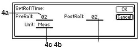
4a. PreRoll.....[00...10]
Specifies the duration of playback that will precede punch-in (IN).
4b. PostRoll ....[00...10]
Specifies the duration of playback that will follow punch-out (OUT).
4c. Unit......[Second, Meas(Measure)]
Selects the unit for setting the pre-roll and post-roll times.
You can choose "Second" or "Meas" (measure). Press the [YES/OK] key to apply the specified pre-roll and post-roll times, or press the [NO/CANCEL] key to cancel any changes.
![KORG D1200CD - 4c. Unit......[Second, Meas(Measure)] - 1](/content/2026/05/820878/images/5ca15971cc39db814d10c65b5a04b2905ec5855f6096ec4ad07277e2bd68ebfb.jpg)
flowchart
graph LR
    A["PreRoll"] --> B["PostRoll"]
    B --> C["OutLOC 1"]
    C --> D["Recording"]
    D --> E["Start recording"]
    D --> F["Stop recording"]
    E --> G["Auto punch-in/out recording"]
    F --> H["LOOP recording (repeat this region)"]
5. Wave ....
Here you can view the audio waveform and set IN and OUT locations more precisely. you can also use the Play From/Play To and Slow Play functions. (→ p.124)
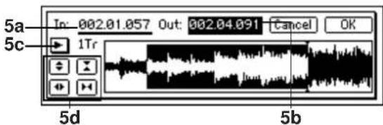
Specifies the IN and OUT points.
When you place the cursor at "In" or "Out," the track chosen in "TrackSelect" will automatically be soloed and the Scrub function will be turned on, so that you will hear only that track when you turn the [VALUE] dial.
5c. TrackSelect .... [Track1...12]
Selects the track whose waveform will be displayed and which will be played. Press the "button" button and choose from the list.
5d. Zoom In/Out/Up/Down......
Adjusts the size of the waveform display and the play-back speed.
◆: Expands the waveform display vertically.
X: Shrinks the waveform display vertically.
◆: Expands the waveform display horizontally.
▶: Shrinks the waveform display horizontally. When you press the [YES/OK] key, the time locations specified for "In" and "Out" will be overwritten onto the [IN/LOC1] and [OUT/LOC2] keys. If you press the [NO/CANCEL] key, your settings will be cancelled.
LOOP
Loop: Settings for loop playback and recording
You can repeatedly play or record over the region specified by the [IN/LOC1] and [OUT/LOC2] times.
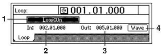
1. Loop.....[On, Off]
![Turns loop playback on/off. Loop:On On: When you play back, the IN- OUT region will be played back repeatedly. If this is "On," the [LOOP] key will light. Loop:Off Off: Playback will occur normally](/content/2026/05/820878/images/29bd014f0319aaff663ad1294e575a8ff7943068a63b42abbe8f6343bf65dbcf.jpg)
2. In ..... (000:00.000...)
Indicates the beginning of the loop. You can set this time by using the [STORE] key and [IN/LOC1] key, or by using the "Wave" display.
3. Out.....(000:00.000...)
Indicates the end of the loop. You can set this time by using the [STORE] key and [OUT/LOC2] key, or by using the "Wave" display.
4. Wave.....
Displays the waveform. By setting the IN and OUT times while you view the waveform, you can make settings more precisely. (→p.109)
TRIGGER
Trigger recording is a function that automatically starts (triggers) recording when the volume of the input signal exceeds the threshold level.
Trigger: Settings for trigger recording
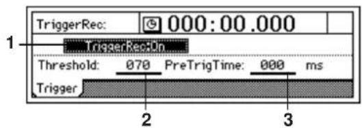
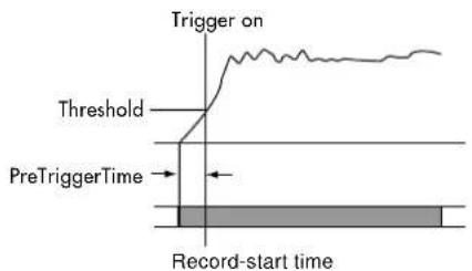
1. TriggerRec..... [On, Off]
Switches the trigger recording function on/off. TriggerRec:On On: When in record-ready mode, recording will begin when the input signal exceeds the threshold level. If this is "On," the [TRIGGER] key will light. Turn "TriggerRec" "On," and then press the [REC] key (LED blinking) to enter record-ready mode. When the input signal to a channel whose [TRACK STATUS] key is set to record exceeds the threshold level, recording will begin automatically. TriggerRec:Off Off: Trigger recording will not occur.
Note Even if this is turned "On," recording will not begin if the input level does not exceed the threshold level while in record-ready mode. In this case, press the [STOP] key or [REC] key to cancel record-ready mode, and then adjust the "Threshold" setting.
2. Threshold.....[000...100]
Specifies the threshold level for the input signal at which recording will be triggered when the trigger recording function is used. Recording will begin when the input level exceeds this setting.
note Normally you should set this as low as possible without allowing recording to be triggered by noise. The appropriate level will depend on the input source. Re-adjust this setting if recording begins too early or too late.
3. PreTrigTime.....[000...700ms]
Specifies the length of sound prior to the record-start time that will be captured when using trigger recording. Trigger recording will start recording when the input signal exceeds the "Threshold" level, but depending on the threshold setting and on the type of source, the initial attack of the first note may be lost. In such cases, you can set the "PreTrigTime" so that the lower-level portion
of the sound that precedes the actual start of recording will also be recorded.
![KORG D1200CD - PreTrigTime.....[000...700ms] - 1](/content/2026/05/820878/images/c9a07d75c1a01608e91427c7f8600996ea821b1a0d6759e7544f5d1ad73ca939.jpg)
This is not valid at the beginning of the song. Also, if you use trigger recording to continue recording after the end of a previously-recorded track, a PreTrigTime setting other than "000 ms" will cause the corresponding length of the previously-recorded sound to be lost.
SCRUB
Here you can switch the Scrub, Play From/Play To, and Slow Play functions on/off.
The setting will alternate between On/Off each time you press the [SCRUB] key.
By using these functions, you can set Locate or Mark times easily and precisely while viewing the waveform.
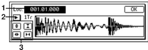
The following functions will be available when the [SCRUB] key is on (LED lit).
- Scrub function: Turn the [VALUE] dial to play back the track data. Use this to find a specific location in the song while you listen to the sound. This method is similar to manually rotating an analog record on a turntable while you listen to the sound to find a desired location.
- Play From function: When you press the [PLAY] key, playback will begin from the location at which you are currently stopped, and will continue for two seconds. Then playback will stop, and you will return to the location at which playback began.
- Play To function: When you hold down the [STOP] key and press the [PLAY] key, playback will begin from a location two seconds earlier than where you are currently stopped, and will continue to that location.
Note By using the Play From function in conjunction with the Play To function, you can find a time location with greater accuracy. -
Slow Play function: When you press the [FF] key, half-speed playback will begin from the location at which you are currently stopped. Press the [STOP] key to stop playback and return to the previous location.
Note The sound will play slowly, at a pitch one octave lower than normal. You can use this function by itself or in conjunction with a pitch shifter to learn difficult or rapidly-played phrases.
When this is "On," the [VALUE] dial is used only for Scrub playback, and cannot be used to set parameter values. -
Loc (Locate) ....[000:00.000...]
Changes the current time location.
You can turn the [VALUE] dial to move the location while listening to the sound and viewing the waveform.
- TrackSelect.....[Trk1...12]
Selects the track that will be played and whose waveform will be displayed.
You can also press the "button and choose from the list.
- Zoom In/Out/Up/Down
Adjusts the size of the waveform display and the play-back speed:
◆: Expands the waveform display vertically.
X: Shrinks the waveform display vertically.
◆: Expands the waveform display horizontally.
▶: Shrinks the waveform display horizontally.
METER/TRACK VIEW
Here you can view the pre-fader level meters and post-fader level meters. You can also use the track view display to check whether each track contains audio events.
From the top, each level meter segment indicates CLIP, -3, -6, -9, -12, -18, -24, -33, -42, -52, and -66 dB.
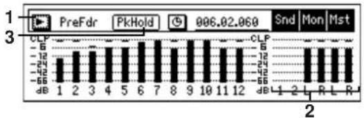
bar
| Position | Value | |---|---| | 1 | -65 | | 2 | -12 | | 3 | -24 | | 4 | -12 | | 5 | -12 | | 6 | -65 | | 7 | -12 | | 8 | -12 | | 9 | -12 | | 10 | -65 | | 11 | -12 | | 12 | -12 | | 1 | -65 | | 2 | -12 | | R | -12 | | L | -12 | | R | -12 | Snd Mon Mst 006.02.0691. Select DisplayMode......
[PreFaderLev, PostFaderLev, TrkView1-6, TrkView7-12, TrkView1-12]
Selects the signals that you want to view.
Press the "button to open the dialog box and make a selection. Press the [YES/OK] key to activate your selection, or press the [NO/CANCEL] key to cancel.
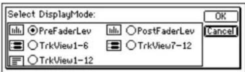
PrefaderLev: Display the pre-fader levels of the mixer channels.
PostFaderLev: Display the post-fader levels of the mixer channels.
TrkView1-6: Display tracks 1-6.
Areas where audio events exist are shown by a heavy line. The current location will always be in the center of the display.
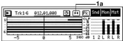
1a. ScaleChangeSW...... [(5, 10, 20, 40)]
Changes the size of the region that is displayed in the track view screen. Each time you press this button, the scale will step through the magnification settings in the range of 5 sec–40 sec. The button will be displayed as
"◀" when expanding the displayed region, and as "◀" when shrinking the displayed region.
5sec: Display five seconds before and after the current locate point.
10sec: Display ten seconds before and after the current locate point.
20sec: Display twenty seconds before and after the current locate point.
40sec: Display forty seconds before and after the current locate point.
TrkView 7-12: Display tracks 7-12 (→“TrkView1-6”)
TrkView 1-12: Display tracks 1-12 ( "TrkView1-6")
2. Snd1, 2/MonL, R/MstL, R ....
These are the level meters for "Snd1, 2" (effect sends 1, 2), "MonL, R" (monitor L, R), and "MstL, R" (master L, R).
note "MstL, R" is also displayed at the right edge of the page in [SONG], [TRACK], [BOUNCE], and [EQ] modes, allowing you to check the master LR level.
3. PkHold..... [0,85,
Specifies the time that the maximum level of the level meter is held in the display.
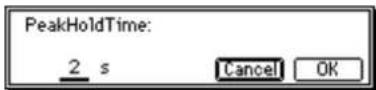
This setting applies to the level meters of all pages. Press the "PkHold" button to open the dialog box, and make the desired setting. Press the [YES/OK] key to apply your selection, or press the [NO/CANCEL] key to cancel it.
0...8s: 0–8 seconds
∞: The peak hold indicator will be held forever. The hold indicator will be cleared when you use the "PkHold" indicator to open the dialog box.
UNDO
After performing one of the following operations, you can use the Undo function to return to the state prior to the operation, and the Redo function to bring back the most recent state.
- Recording
- T rack editing
Copy Track, Insert Track, Erase Track, Delete Track, Swap Track, Reverse Track, Optimize Track, Exp/Comp Track, Copy Whole Track, Swap Whole Track, Fade Track, Normalize Track
• W AV file import
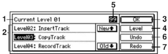
- Current Level..... (00...99)
Indicates the currently selected undo level; i.e., how many operations prior to the present. Current Level 00: The most recent state Current Level 01...99: The state prior to the previous operation – the previous 99 operations
- Undo List ....[Level01...99]
This area displays the undo levels and the operation history. Press the "New" button to select an earlier level. Press the "Old" button to select a later level.
- OK
Return to the page in which you were before pressing the [UNDO] key.
- Level.....[99Level, 8Level, 1Level]
Specifies the undo level. Data will be saved for as many prior operations as you specify here. You can select 99 operations, 8 operations, or 1 operation as the undo level.
- Undo Level......
Indicates the undo level that is selected by "Level."
- Undo....
Executes the Undo. You will return to the state prior to executing the operation selected in the "UndoList."
- Redo ....
Executes Redo. You will return to the "Level 00" state.
The content of the list are maintained until the next recording or track editing pattern. When you record or edit, the data will be deleted for levels subsequent to executing the last undo. The contents of the list will also be deleted when you select a different song, and record or edit.
The hard disk of the D1200 maintains an operation history for up to the last 99 recording and editing operations, letting you use the Undo function to return to an earlier state of your work. This means that old data that no longer exists in a track will remain on the disk with-
out being deleted. This will consume disk space, and may cause the available recording time to appear shorter. In such cases you can recover this disc capacity by turning off the power of the D1200 to delete the Undo history.
Effect Parameter List
Example
Algorithm number: Category number: Algorithm name
1: RV1: Reverb Hall
Parameter name shown on screen..... Range of parameter Explanation (parameter name)
*Time (Reverb Time [sec]) 01...10.0s Sets the reverberation time
* Parameters marked by an “*” in front of the screen parameter name can be controlled by an external device such as an expression pedal. (→p.101 "Device")
Insert (2in2outx2)/Master/Final Effect
These algorithms can be selected for an insert effect if "2in2outx2" is selected for "SelectEffType". They can also be selected for a master effect or a final effect.

When these effects are used as an insert effect or final effect, they are stereo-in/stereo-out. However when these effects are used as a master effect, they are mono-in/stereo-out.
Reverb RV1 - RV7
Category: Reverb-type effects
1: RV1: Reverb Hall
This hall-type reverb simulates the reverberation of mid-size concert halls or ensemble halls.
2: RV2: Smooth Hall
This hall-type reverb simulates the reverberation of larger halls and stadiums, and creates a smooth release.
3: RV3: Reverb Wet Plate
This plate reverb simulates warm (dense) reverberation.
4: RV4: Reverb Dry Plate
This plate reverb simulates dry (light) reverberation.
| Time (Reverb Time [sec]) | 0.1...10.0s Sets the reverberation time |
| HiDamp (High Damp [%]) | 0...100 Sets the damping amount in the high range |
| PreDly (Pre Delay [msec]) | 0...200ms Sets the delay time from the dry sound |
| Thru (Pre Delay Thru [%]) | 0...100 Sets the mix ratio of non-delay sound |
| EQTrim (EQ Trim) | 0...100 Sets the EQ input level |
| LEQG (Pre LEQ Gain [dB]) | -15...+15dB Sets the gain of Low EQ |
| HEQG (Pre HEQ Gain [dB]) | -15...+15dB Sets the gain of High EQ |
| Mix (Wet/Dry) | Dry, 1:99...99:1, Wet Sets the balance between the effect and dry sounds |
: Pre Delay [msec], : Pre Delay Thru [%]
The "Pre Delay" sets the delay time to the reverb input, allowing you to control spaciousness.
Using the "Pre Delay Thru" parameter, you can mix the dry sound without delay, emphasizing the attack of the sound.
5: RV5: Reverb Room
This room-type reverb emphasizes the early reflections that make the sound tighter. Changing the balance between the early reflections and reverb sound allows you to simulate nuances, such as the type of walls of a room.
6: RV6: Bright Room
This room-type reverb emphasizes the early reflections that make the sound brighter.
| Time (Reverb Time [sec])......0.1...3.0s Sets the reverberation time |
| HiDamp (High Damp [%])......0...100 Sets the damping amount in the high range |
| PreDly (Pre Delay [msec])......0...200ms Sets the delay time from the dry sound |
| Thru (Pre Delay Thru [%])......0...100 Sets the mix ratio of non-delay sound |
| ERLvl (ER Level)......0...100 Sets the level of early reflections |
| RvbLvl (Reverb Level)......0...100 Sets the reverberation level |
| EQTrim (EQ Trim)......0...100 Sets the EQ input level |
| LEQG (Pre LEQ Gain [dB])......-15...+15dB Sets the gain of Low EQ |
| HEQG (Pre HEQ Gain [dB])......-15...+15dB Sets the gain of High EQ |
| Mix (Wet/Dry)......Dry, 1:99...99:1, Wet Sets the balance between the effect and dry sounds |
: ER Level, : Reverb Level
These parameters set the early reflection level and reverb level. Changing these parameter values allows you to simulate the type of walls in the room. That is, a larger "ER Level" simulates a hard wall, and a larger "Reverb Level" simulates a soft wall.
7: RV7: Early Reflection
This effect is only the early reflection part of a reverberation sound, and adds presence to the sound. You can select one of the four decay curves.
| Type (Type) ......Sharp, Loose; Selects the decay curve for the early Modula, Revers reflection | |
| ERTime (ER Time [msec]) ...... 10...800ms Sets the time length of early reflection | |
| PreDly (Pre Delay [msec]) ...... 0...200ms Sets the time taken from the original sound to the first early reflection | |
| EQTrim (EQ Trim)...... 0...100 Sets the input level of EQ applied to the effect sound | |
| LEQG (Pre LEQ Gain [dB])...... -15.0...+15.0 Sets the gain of Low EQ | |
| HEQG (Pre HEQ Gain [dB]) .... -15.0...+15.0 Sets the gain of High EQ | |
| Mix (Wet/Dry) ......Dry, 1:99...99:1, Wet Sets the balance between the effect and dry sounds |
:Type
This parameter selects the decay curve for the early reflection.
Delay DL1 - DL6
Category: Delay-type effects
8: DL1: L/C/R Delay
This multitap delay outputs three Tap signals to the left, right, and center respectively. You can also adjust the left and right spread of the delay sound.
| LTime (L Delay Time [msec])......0...1360ms Sets the delay time of TapL |
| LLevel (Level)......0...50 Sets the output level of TapL |
| CTime (C Delay Time [msoc])......0...1360ms Sets the delay time of TapC |
| CLevel (Level)......0...50 Sets the output level of TapC |
| RTime (R Delay Time [msec])......0...1360ms Sets the delay time of TapR |
| RLevel (Level)......0...50 Sets the output level of TapR |
Fdback (Feedback (C Delay))..... -100...+100 Sets the feedback amount of TapC
HIDamp (High Damp [%]) .... 0...100 Sets the damping amount in the high range
LoDamp (Low Damp [%]).... 0...100 Sets the damping amount in the low range
Spread (Spread) 0...50 Sets the width of the stereo image of the effect sound
Mix (Wet/Dry) ....Dry, 1:99...99:1, Wet Sets the balance between the effect and dry sounds
: High Damp [%], : Low Damp [%]
These parameters set the damping amount of high range and low range. The tone of the delayed sound becomes darker and lighter as it feeds back.
: Spread
This parameter sets the pan width of the effect sound. The stereo image is widest with a value of "50," and the effect sound of both channels is output from the center with a value of "0."
9: DL2: St/Cross Delay (Stereo/Cross Delay)
This is a stereo delay, and can be used as a cross-feedback delay effect in which the delay sounds cross over between the left and right by changing the feedback routing.
Mode (Stereo/Cross).... Stereo, Cross Switches between stereo delay and cross-feedback delay
LTime (L Delay Time [msec]) ...... 0...680ms Sets the delay time for the left channel
RTime (R Delay Time [msec]) ...... 0...680ms Sets the delay time for the right channel
LFback (L Feedback) ...... -100...+100 Sets the feedback amount for the left channel
RFback (R Feedback)....-100...+100 Sets the feedback amount for the right channel
HiDamp (High Damp [%]) .... 0...100 Sets the damping amount in the high range
LoDamp (Low Damp [%]).... 0...100 Sets the damping amount in the low range
Spread (Spread) ...... -50...+50 Sets the width of the stereo image of the effect sound
Mix (Wet/Dry) ....Dry, 1:99...99:1, Wet Sets the balance between the effect and dry sounds
10: DL3: St.Multitap Delay (Stereo Multitap Delay)
The left and right Multitap Delays have two taps respectively. Changing the routing of feedback and tap output allows you to create various patterns of complex effect sounds.
Mode (Mode)..... Normal, X.Fback, Switches the left and right delay routing X.Pan1, X.Pan2
T1Time (Tap1 Time [msec]) .... 0...680ms Sets the Tap1 delay time
T2Time (Tap2 Time [msec]) .... 0...680ms Sets the Tap2 delay time
T1Lvl (Tap1 Level).... 0...100 Sets the Tap1 output level
Fdback (Feedback) ...... -100...+100 Sets the Tap2 feedback amount
HiDamp (High Damp [%]) .... 0...100 Sets the damping amount in the high range
LoDamp (Low Damp [%]).... 0...100 Sets the damping amount in the low range
Spread (Spread) ....-100...+100 Sets the width of the stereo image of the effect sound
Mix (Wet/Dry) ....Dry, 1:99...99:1, Wet Sets the balance between the effect and dry sounds
: Mode
The left/right panning of the delay can be modified by changing the connections of the left and right delay. Be aware that different sounds must be input to the left and right channels in order for this parameter to be effective.
: Tap1 Level
This parameter sets the output level of Tap1. Setting a different level from Tap2 will add a unique touch to a monotonous delay and feedback.
11: DL4: St.Modulation Delay (Stereo Modulation Delay)
This stereo delay uses an LFO to sweep the delay time. The pitch also varies. You will obtain a delay sound with swell and shimmering.
LFO (LFO Waveform) ..... TRI, SIN Selects LFO Waveform
Shape (LFO Shape) ....-100...+100 Determines how much the LFO waveform is changed
*Speed (LFO Frequency [Hz]).... 0.02...20.0Hz Sets the LFO speed
LPhase (L LFO Phase [degree]). -180...+180 Sets the phase obtained when the left LFO is reset
RPhase(R LFO Phase [degree]) .-180...+180 Sets the phase obtained when the right LFO is reset
* LDepth (L Depth) ....0...200 Sets the depth of the left LFO modulation
*RDepth (R Depth)....0...200 Sets the depth of the right LFO modulation
LTime (L Delay Time [msec])..... 0...500 Sets the delay time for the left channel
RTime (R Delay Time [msec]) ....0...500 Sets the delay time for the right channel
LFback (L Feedback)....-100...+100 Sets the feedback amount of left delay
RFback (R Feedback) ......-100...+100 Sets the feedback amount of right delay
Mix (Wet/Dry) ....-Wet...-1:99, Dry, Sets the balance between the effect and 1:99...Wet dry sounds
: L LFO Phase [degree], : R LFO Phase [degree]
"L LFO Phase" and "R LFO Phase" specify the phase difference between the two LFO's when they are reset. This allows the pitch change of the sweep to be set independently for left and right.
12: DL5: St.Dynamic Delay (Stereo Dynamic Delay)
This stereo delay controls the level of delay according to the input signal level. You can use this as a ducking delay that applies delay to the sound only when you input signals at a high velocity or only when the volume level is low.
Contrl (Control Target) .... None, Out, FB Selects from no control, output, and feedback
Polrty (Polarity) +, - Reverses level control
Thrshl (Threshold) 0...100 Sets the level to which the effect is applied
Offset (Offset)....0...100 Sets the offset of level control
Attack (Attack) ....1...100 Sets the attack time of level control
Relse (Release)....1...100 Sets the release time of level control
LTime (L Delay Time [msec])..... 0...680ms Sets the delay time for the left channel
RTime (R Delay Time [msec]) .....0...680ms Sets the delay time for the right channel
Fdback (Feedback)....-100...+100 Sets the feedback amount
HiDamp (High Damp [%])....0...100 Sets the damping amount in the high range
LoDamp (Low Damp [%]) ....0...100 Sets the damping amount in the low range
Spread (Spread)....-100...+100 Sets the width of the stereo image of the effect sound
Mix (Wet/Dry) .... Dry, 1:99...99:1, Wet Sets the balance between the effect and dry sounds
: Control Target
This parameter selects no level control, delay output control (effect balance), or feedback amount control.
: Polarity, :Threshold, :Offset, :Attack, :Release
The "Offset" parameter specifies the value for the "Control Target" parameter (when level control is not being applied), expressed as a ratio relative to the parameter setting. The parameter setting will be the "Wet/Dry" value if "Control Target" = "Out," or the "Feedback" value if "Control Target" = "FB."
When "Polarity" is "+" the "Control Target" value is obtained by multiplying the parameter value by the "Offset" value (if the input level is below "Threshold"), or will equal the parameter value if the input level exceeds the threshold.
When "Polarity" is “−”, the Control Target value will equal the parameter value if the input level is below "Threshold", or is obtained by multiplying the parameter value by the "Offset" value if the input level exceeds "Threshold."
The "Attack" and "Release" parameters specify attack time and release time of delay level control.
13: DL6: St.Auto Panning Delay (Stereo Auto Panning Delay)
This stereo delay effect pans the delay sound left and right using the LFO.
| LTime (L Delay Time [msec])......0...680ms Sets the delay time for the left channel |
| LFback (L Feedback)......-100...+100 Sets the feedback amount for the left channel |
| RTime (R Delay Time [msec])......0...680ms Sets the delay time for the right channel |
| RFback (R Feedback)......-100...+100 Sets the feedback amount for the right channel |
| HiDamp (High Damp [%])......0...100 Sets the damping amount in the high range |
| LoDamp (Low Damp [%])......0...100 Sets the damping amount in the low range |
| LFO (LFO Waveform)......TRI, SIN Selects LFO Waveform |
| Shape (LFO Shape)......-100...+100 Determines how much the LFO waveform is changed |
| Phase (LFO Phase [degree])......-180...+180 Sets the LFO phase difference between the left and right |
| *Speed(Panning Frequency [Hz]).......Sets the panning speed0.02...20.0Hz |
| *Depth (Panning Depth)....0...100 Sets the panning width | |
| Mix (Wet/Dry)....Dry, 1:99...99:1, Wet | Sets the balance between the effect and dry sounds |
Modulation MO1–MO7 Category: Modulation-type effects
14: MO1: St.Chorus (Stereo Chorus)
This effect adds thickness and warmth to the sound by modulating the delay time of the input signal. A two-band equalizer can be used to adjust the tone of the effect sound. You can control the spaciousness of the sound by offsetting the phase of the left and right LFOs from each other.
| LFO (LFO Waveform) ..... TRI, SIN Selects LFO Waveform |
| Phase (LFO Phase [degree]) .....-180...+180 Sets the LFO phase difference between the left and right |
| *Speed (LFO Frequency [Hz])..... 0.02...20.0Hz Sets the LFO speed |
| LDly (L Pre Delay [msec]).....0.0...50.0ms Sets the delay time for the left channel |
| RDly (R Pre Delay [msec]) ..... 0.0...50.0ms Sets the delay time for the right channel |
| *Depth (Depth) .....0...100 Sets the depth of LFO modulation |
| EQTrim (EQ Trim) .....0...100 Sets the EQ input level |
| LEQG (Pre LEQ Gain [dB]) .....-15.0...+15.0 Sets the gain of Low EQ |
| HEQG (Pre HEQ Gain [dB]) .....-15.0...+15.0 Sets the gain of High EQ |
| Mix (Wet/Dry) ...-Wet...-1:99, Dry, 1:99...Wet Sets the balance between the effect and dry sounds |
: L Pre Delay [msec], : R Pre Delay [msec]
Setting the left and right delay time individually allows you to control the stereo image.
15: MO2: St.Flanger (Stereo Flanger)
This effect gives a significant swell and movement of pitch to the sound. It is more effective when applied to a sound with a lot of harmonics. This is a stereo flanger. You can add spread to the sound by offsetting the phase of the left and right LFOs from each other.
| Time (Delay Time [msec])......0.0...50.0ms Sets the delay time from the original sound |
| LFO (LFO Waveform) ...... TRI, SIN Selects LFO Waveform |
| Shape (LFO Shape) ......-100...+100 Determines how much the LFO waveform is changed |
Phase (LFO Phase [degree])..... -180...+180 Sets the LFO phase difference between the left and right
*Speed (LFO Frequency [Hz]) ....0.02...20.0Hz Sets the LFO speed
*Depth (Depth).... 0...100 Sets the depth of LFO modulation
Fdback (Feedback) ...... -100...+100 Sets the feedback amount
HiDamp (High Damp [%]) .... 0...100 Sets the feedback damping amount in the high range
Mix (Wet/Dry)....-Wet...-1:99, Dry, Sets the balance between the effect and 1:99...Wet dry sounds
:LFO Shape
Changing the LFO waveform shape controls the peak sweep of flanging effects.
The peak shape of the positive and negative "Feedback" value is different. The harmonics will be emphasized when the effect sound is mixed with the dry sound if you set a positive value for both "Feedback" and "Wet/Dry", and if you set a negative value for both "Feedback" and "Wet/Dry".
: High Damp [%]
This parameter sets the amount of damping of the feedback in the high range. Increasing the value will cut high-range harmonics.
16: MO3: St.Phaser (Stereo Phaser)
This effect creates a swell by shifting the phase. It is very effective on electric piano sounds. This is a stereo effect, and you can control the spaciousness of the sound by offsetting the phase of the left and right LFOs from each other.
| LFO (LFO Waveform).... TRI, SIN Selects LFO Waveform | |
| Shape (LFO Shape).... -100...+100 Determines how much the LFO wave-form is changed | |
| Phase (LFO Phase [degree]).... -180...+180 Sets the LFO phase difference betweenthe left and right | |
| *Speed (LFO Frequency [Hz]) ....0.02...20.0Hz Sets the LFO speed | |
| Manual (Manual).... 0...100 Sets the frequency to which the effect isapplied | |
| *Depth (Depth).... 0...100 Sets the depth of LFO modulation | |
| Reso (Resonance).... -100...+100 Sets the resonance amount | |
| HiDamp (High Damp [%]) .... 0...100 Sets the resonance damping amount inthe high range | |
| Mix (Wet/Dry) ... -Wet...-1:99, Dry, 1:99...Wet Sets the balance between the effect anddry sounds |
: Resonance, : Wet/Dry
The peak shape of the positive and negative Feedback value is different. The harmonics will be emphasized when the effect sound is mixed with the dry sound, if you set a positive value for both "Resonance" and "Wet/Dry", and if you set a negative value for both "Resonance" and "Wet/Dry".
: High Damp [%]
This parameter sets the amount of damping of the resonance in the high range. Increasing the value will cut high-range harmonics.
This effect causes the pitch of the input signal to shimmer. You can use an expression pedal etc. to gradually increase or decrease the shimmering speed.
| LFO (LFO Waveform).... TRI, SIN Selects LFO Waveform |
| Shape (LFO Shape).... -100...+100 Determines how much the LFO wave-form is changed |
| *Speed (LFO Frequency [Hz]) ...0.02...20.0Hz Sets the LFO speed |
| *Depth (Depth).... 0...100 Sets the depth of LFO modulation |
| Mix (Wet/Dry) ....Dry, 1:99...99:1, Wet Sets the balance between the effect and dry sounds |
18: MO5: St.Tremolo (Stereo Tremolo)
This effect modulates the volume level of the input signal. The effect is stereo, and offsetting the LFO of the left and right phases from each other produces a tremolo effect between left and right.
| LFO (LFO Waveform)......TRI, SIN, Vintage, Selects LFO Waveform Up, Down | |
| Shape (LFO Shape)...... | -100...+100 Determines how much the LFO wave-form is changed |
| Phase (LFO Phase [degree])...... | -180...+180 Sets the LFO phase difference between the left and right |
| *Speed (LFO Frequency [Hz]) .... 0.02...20.0Hz Sets the LFO speed | |
| *Depth (Depth)...... | 0...100 Sets the depth of LFO modulation |
| Mix (Wet/Dry) ......Dry, 1:99...99:1, Wet Sets the balance between the effect and dry sounds | |
:LFO Waveform
This parameter selects the LFO waveform. "Vintage" wave simulates the characteristics of the tremolo created on a guitar amplifier. Combining this effect with the Amp Simulation will make a realistic, vintage tremolo amplifier sound.
:LFO Phase [degree]
This parameter determines the difference between the left and right LFO phases. A higher value will simulate the auto-pan effect in which the sound is panned between left and right.
19: MO6: St.Auto Pan (Stereo Auto Pan)
This Auto Pan effect pans sound between left and right. It is stereo, and shifting the left and right LFO phases from each other will simulate the sound of the left and right channels crossing over each other by turns, or chasing each other.
| LFO (LFO Waveform).... TRI, SIN Selects LFO Waveform | |
| Shape (LFO Shape).... -100...+100 Determines how much the LFO wave-form is changed | |
| Phase (LFO Phase [degree]).... -180...+180 Sets the LFO phase difference between the left and right | |
| *Speed (LFO Frequency [Hz]) .... 0.02...20.0Hz Sets the LFO speed | |
| *Depth (Depth).... 0...100 Sets the depth of LFO modulation | |
| Mix (Wet/Dry)....Dry, 1:99...99:1, Wel Sets the balance between the effect and dry sounds |
:LFO Shape
You can change the panning curve by modifying the LFO waveform.
:LFO Phase
This parameter determines the difference in the left and right LFO phases. When you change the value gradually from "0," the sound from the left and right channels will chase each other around. If you set the parameter to "+180" or "-180," the sound from each channel will cross over each other. You need to input different sounds to each channel in order for this parameter to be effective.
20: MO7: Ensemble
This Ensemble effect has three chorus blocks that use LFO to create subtle shimmering, and gives three dimensional depth and spread to the sound, because the signal is output from the left, right, and center.
| *Speed (Speed)...... 1...100 Sets the LFO speed |
| *Depth (Depth)...... 0...100 Sets the depth of LFO modulation |
| Shimmr (Shimmer)...... 0...100 Sets the amount of shimmering of the LFO waveform |
| Mix (Wet/Dry) ......Dry, 1:99...99:1, Wet Sets the balance between the effect and dry sounds |
: Shimmer
This parameter sets the amount of shimmering of the LFO waveform. Increasing this value adds more shimmering, making the chorus effect more complex and richer.
Dynamics DY1 - DY7
Category: Dynamics-type effects
21: DY1: St.Compressor (Stereo Compressor)
This effect compresses the input signal to regulate the level and give a "punchy" effect. It is useful for guitar, piano, and drum sounds. This is a stereo compressor. You can link left and right channels, or use each channel separately.
| Envelop (Envelope Select) ...... L/RMix, Indivi Determines whether the left and right channels are linked or used separately |
| Sens (Sensitivity)......1...100 Sets the sensitivity |
| Attack (Attack) ......1...100 Sets the attack level |
| EQTrim (EQ Trim) ...... 0...100 Sets the EQ input level |
| LEQG (Pre LEQ Gain [dB]) ......-15.0...+15.0 Sets the gain of Low EQ |
| HEQG (Pre HEQ Gain [dB]) ......-15.0...+15.0 Sets the gain of High EQ |
| Level (Output Level) ...... 0...100 Sets the output level of the compressor |
| Mix (Wet/Dry) ...... Dry, 1:99...99:1, Wet Sets the balance between the effect and dry sounds |
:Envelope Select
This parameter selects whether the left and right channels are linked to control both signals simultaneously, or whether each channel is controlled independently.
: Sensitivity, : Output Level
The "Sensitivity" parameter sets the sensitivity of the compressor. If this parameter is set to a higher value, lower level sounds will be boosted. With a higher Sensitivity, the overall volume level is higher. To adjust the final volume level, use the "Output Level" parameter.
:Attack
Controls the strength of the attack that is characteristic of a compressor.
22: DY2: St.Limiter (Stereo Limiter)
The Limiter regulates the input signal level. It is similar to the Compressor, except that the Limiter compresses only signals that exceed the specified level to lower unnecessary peak signals. The Limiter applies a peaking-type EQ to the trigger signal (which controls the degree of the Limiter effect), allowing you to set any band width to be covered. This effect is a stereo limiter. You can link left and right channels, or use each channel individually.
| Envelop (Envelope Select) .....L/RMix, L Only, Selects from linking both channels, controlling only from left channel, only from the right channel, or controlling each channel individually | |
| Ratio (Ratio) .....1.0:1...50.0:1, Inf:1 Sets the signal compression ratio | |
| Thrshl (Threshold [dB]) .....-40...0dB Sets the level above which the compressor is applied | |
| Attack (Attack) .....1...100 Sets the attack time | |
| Relse (Release) .....1...100 Sets the release time | |
| GLevel (Gain Adjust [dB]) .....-Inf, Sets the output gain -38...+24dB | |
| SPEQ (Side PEQ Insert) .....Off, On Toggles between on/off of the trigger signal's EQ | |
| Triggr (Trigger Monitor) .....Off, On Switches between effect output monitor and trigger signal monitor | |
| Mix (Wet/Dry) .....Dry, 1:99...99:1, Wet Sets the balance between the effect and dry sounds | |
| Fc (Side PEQ Cutoff [Hz]) .....20...12.0kHz Sets the EQ center frequency for the trigger signal | |
| Q (Q) .....0.5...10.0 Sets the EQ bandwidth for the trigger signal | |
| Gain (Gain [dB]) .....-18.0...+18.0 Sets the EQ gain for the trigger signal |
:Envelope Select
When "L/R Mix" is selected for this parameter, the left and right channels are linked to control the Limiter using the mixed signal. If "L Only" (or "R Only") is selected, the left and right channels are linked, and the Limiter is controlled via only the left (or right) channel.
With "indivi", the left and right channels control the Limiter individually.
: Ratio, : Threshold [dB], : Gain Adjust [dB]
This parameter sets the signal compression "Ratio". Compression is applied only when the signal level exceeds the "Threshold" value. In the case of the limiter, applying compression will lower the overall level, so you should use "Gain Adjust" to make adjustments.
: Attack, : Release
These parameters set the attack time and release time. A higher attack time will cause the compression to be applied more slowly.
: Side PEQ Insert, : Side PEQ Cutoff [Hz], : Q, : Gain [dB]
These parameters are used to set the EQ applied to the trigger signal.
The Limiter determines whether the compression is applied or not, based on the post-EQ trigger signal. Setting the equalizer allows you to set the Limiter to respond to any frequency band.
: Trigger Monitor
Setting this parameter "On" will cause the trigger signal to be output, instead of the effect sound. Use this parameter to check the trigger signal with EQ applied.
Usually, set this to "Off."
23: DY3: Multiband Limiter
This effect applies the Limiter to the low range, mid range, and high range of the input signal. You can control dynamics for each range to adjust the sound pressure of the low range, mid range, and high range in a different way from the EQ.
| Ratio (Ratio) | 1.0:1...50.0:1, Inf:1 Sets the signal compression ratio |
| Thrshl (Threshold [dB]) | -40...0dB Sets the level above which the compressor is applied |
| Attack (Attack) | 1...100 Sets the attack time |
| Relse (Release) | 1...100 Sets the release time |
| LoOfst (Low Offset [dB]) | -40...0dB Sets the low range gain of trigger signal |
| MdOfst (Mid Offset [dB]) | -40...0dB Sets the mid range gain of trigger signal |
| HiOfst (High Offset [dB]) | -40...0dB Sets the high range gain of trigger signal |
| GLevel (Gain Adjust [dB]) | -Inf, -38...+24dB Sets the output gain |
| Mix (Wet/Dry) | Dry, 1:99...99:1, Wet Sets the balance between the effect and dry sounds |
: Low Offset [dB], : Mid Offset [dB], : High Offset [dB]
These parameters set the gain of the trigger signal.
For example, if you do not want to apply compression to the high range, reduce the "High Offset" value down below the "Threshold" level. In this way, the high range limiter will not respond, and compression will not be applied.
24: DY4: St.Gate (Stereo Gate)
This effect mutes the input signal if its level is lower than the specified level. It also reverses the on and off operation of the gate, and uses Note On and Off messages to turn the gate on and off.
| Envelop (Envelope Select) ..... L/RMix, L Only, Selects from Control via the modulation | |
| R Only source, mixing the left and right signals,Only left, and Only right | |
| Polity (Polarity) .....+, - Switches between non-reversed andreversed Gate on/off | |
| Thrshl (Threshold) .....0...100 Sets the level to which the Gate isapplied | |
| Attack (Attack) .....1...100 Sets the attack time | |
| Relse (Release) .....1...100 Sets the release time | |
| DTime (Delay Time [msec]) ..... 0...100ms Sets the delay time of the gate input | |
| Mix (Wet/Dry) ..... Dry, 1:99...99:1, Wet Sets the balance between the effect anddry sounds | |
With "Envelope Select" = "L/R Mix," the left and right channel signal mixture will trigger the gate on/off. When "L Only" or "R
Only" is selected, the gate is controlled by either of the channel signals.
: Polarity
This parameter reverses the Gate on/off operation. With a negative value, the gate is closed when the input signal level exceeds the Threshold.
:Attack, :Release
The Attack and Release parameters set the Gate attack time and release time.
: Delay Time
This parameter sets the delay time of the Gate input. If the sound has a very fast attack, increase the delay time so that the signal will be input after the Gate is opened.
25: DY5: St. Exciter/Enhancer (Stereo Exciter/Enhancer)
This effect is a combination of the Exciter, which adds a punch to the sound and the Enhancer, which adds spread and presence.
| Blend (Exciter Blend) ...... -100...+100 Sets the intensity (depth) of the Exciter effect |
| Empha (Emphatic Point) ...... 0...140 Sets the frequency to be emphasized |
| LDly (Enhancer Dly L [msec]) .... 0.0...50.0ms Sets the delay time for the Enhancer left channel |
| RDly (Enhancer Dly R [msec])... 0.0...50.0ms Sets the delay time for the Enhancer right channel |
| *Depth (Enhancer Depth) ...... 0...100 Sets the determines to what degree the Enhancer effect is applied |
| EQTrim (EQ Trim)...... 0...100 Sets the 2-band EQ input level |
| LEQG (Pre LEQ Gain [dB])...-15.0...+15.0dB Sets the gain of Low EQ |
| HEQG (Pre HEQ Gain [dB]).-15.0...+15.0dB Sets the gain of High EQ |
| Mix (Wet/Dry) ......Dry, 1:99...99:1, Wet Sets the balance between the effect and dry sounds |
: Exciter Blend
This parameter sets the depth (intensity) of the Exciter effect. Positive values give a frequency pattern (to be emphasized) different from negative values.
: Emphatic Point
This parameter sets the frequency to be emphasized. Higher values will emphasize lower frequencies.
: Enhancer Dly L [msec], : Enhancer Dly R [msec]
These parameters set the delay time for the Enhancer left and right channel. Specifying a slightly different delay time for the left and right channel will add a stereo image, depth, and width to the sound.
26: DY6: St.Decimator (Stereo Decimator)
This effect creates a rough sound like a cheap sampler by lowering the sampling frequency and data bit length. You can also simulate noise unique to a sampler (aliasing).
| LPF (Pre LPF)....Off, On Selects whether the harmonic noise caused by a decrease in sampling frequency is generated or not | |
| Fs (Sampling Frequency [Hz]) ....1.0k...44.1k Sets the sampling frequency | |
| Bit (Resolution) ...... 4..24 Sets the data bit length | |
| Speed (LFO Frequency [Hz]) .... 0.02...20.0Hz Sets the LFO speed | |
| *Depth (Depth).... 0...100 Sets the depth of the sampling frequency modulation | |
| HiDamp (High Damp [%]) ...... 0...100 Sets the ratio of cut of the high range | |
| Level (Output Level).... 0...100 Sets the output level | |
| Mix (Wet/Dry) ....Dry, 1:99...99:1, Wet Sets the balance between the effect and dry sounds |
: Pre LPF
If a sampler with a very low sampling frequency receives very high-pitched sound that could not be heard during playback, it could generate pitch noise that is unrelated to the original sound. Set "Pre LPF" to "On" to prevent this noise from being generated. If you set the "Sampling Frequency" to about "3kHz" and set "Pre LPF" to "Off," you can create a sound like a ring modulator.
: Resolution, : Output Level
If you set a smaller value for the "Resolution" parameter, the sound may be distorted. The volume level may also be changed. Use "Output Level" to adjust the level.
27: DY7: St.Parametric 4band EQ (Stereo Parametric 4band EQ)
This is a stereo 4-band parametric equalizer. You can select peaking type or shelving type for Band 1 and 4.
| Trim (Trim)......0...100 Sets the input level |
| B1Type (Band1 Type)...... Peaking, ShelvL Selects the type of Band 1 |
| B4Type (Band4 Type)...... Peaking, ShelvH Selects the type of Band 4 |
| Fc1 (Band1 Cutoff [Hz])......20...1.0kHz Sets the center frequency of Band 1 |
| Q1 (Q)......0.5...10.0 Sets the bandwidth of Band 1 |
| G1 (Gain [dB])......-18.0...+18.0 Sets the gain of Band 1 |
| Fc2 (Band2 Cutoff [Hz])......50...10.0kHz Sets the center frequency of Band 2 |
| Q2 (Q)......0.5...10.0 Sets the bandwidth of Band 2 |
| G2 (Gain [dB])......-18.0...+18.0 Sets the gain of Band 2 |
| Fc3 (Band3 Cutoff [Hz])......300...10.0kHz Sets the center frequency of Band 3 |
| Q3 (Q)......0.5...10.0 Sets the bandwidth of Band 3 |
| G3 (Gain [dB])......-18.0...+18.0 Sets the gain of Band 3 |
| Fc4 (Band4 Cutoff [Hz])......500...20.0kHz Sets the center frequency of Band 4 |
| Q4 (Q)......0.5...10.0 Sets the bandwidth of Band 4 |
| G4 (Gain [dB])......-18.0...+18.0 Sets the gain of Band 4 |
| Mix (Wet/Dry)......Dry, 1:99...99:1, Wet Sets the balance between the effect and dry sounds |
: Band1 Type, : Band4 Type
Selects a filter type for Band 1 and 4.
Special Effect SE1 - SE4
Category: Special Effect
28: SE1: St.Ring Modulator (Stereo Ring Modulator)
This effect creates a metallic sound by applying the oscillators to the input signal.
| LPFLvl (Pre LPF) | 0...100 Sets the damping amount of the high range input to the ring modulator |
| Fc (Fixed Frequency [Hz]) | 0...12.0kHz Sets the oscillator frequency when OSC Mode is set to Fixed |
| Speed (LFO Frequency [Hz]) | 0.02...20.0Hz Sets the LFO speed of the oscillator frequency modulation |
| Depth (LFO Depth) | 0...100 Sets the depth of LFO modulation for the oscillator frequency |
| Mix (Wet/Dry) | Dry, 1:99...99:1, Wet Sets the balance between the effect and dry sounds |
: Pre LPF
This parameter enables you to set the damping amount of the high range sound input to the ring modulator. If the input sound contains lots of harmonics, the effect may sound dirty. In this case, cut a certain amount of high range.
: Fixed Frequency [Hz]
This parameter sets the oscillator frequency.
29: SE2: Doppler
This effect simulates the "Doppler effect" of a moving sound with a changing pitch, similar to the siren of an passing ambulance. Mixing the effect sound with the dry sound will create a unique chorus effect.
| *Speed (LFO Frequency [Hz]) ....0.02...20.0Hz Sets the LFO speed | |
| *Pitch (Pitch Depth).... 0...100 Sets the pitch variation of the moving sound | |
| *Pan (Pan Depth).... -100...+100 Sets the panning of the moving sound |
| Mix (Wet/Dry) ...... Dry, 1:99...99:1, Wet Sets the balance between the effect and dry sounds |
: Pitch Depth
With the Doppler effect, the pitch is raised when the sound approaches, and the pitch is lowered when the sound goes away. This parameter sets this pitch variation.
: Pan Depth
This parameter sets the width of the stereo image of the effect sound. With larger values, the sound seems to come and go from much further away. With positive values, the sound moves from left to right; with negative values, the sound moves from right to left.
30: SE3: St.Analog Record (Stereo Analog Record)
This effect simulates the noise caused by scratches and dust on analog records. It also reproduces some of the modulation caused by a warped turntable.
| RPM (Speed [RPM])......33 1/3, 45, 78 Sets the r.p.m. of a record*Wah (Flutter)......0...100 Sets the modulation depth |
| NsDens (Noise Density)......0...100 Sets the noise density |
| NsTone (Noise Tone)......0...100 Sets the noise tone |
| NsLvl (Noise Level)......0...100 Sets the noise level |
| ClkLvl (Click Level)......0...100 Sets the click noise level |
| EQTrim (EQ Trim)......0...100 Sets the EQ input level |
| Fc (Pre EQ Cutoff [Hz])......300...10.0kHz Sets the EQ center frequency |
| Q (Q)......0.5...10.0 Sets the EQ band width |
| GLevel (Gain [dB])......-18.0...+18.0 Sets the EQ gain |
| Mix (Wet/Dry)......Dry, 1:99...99:1, Wet Sets the balance between the effect and dry sounds |
: Flutter
This parameter enables you to set the depth of the modulation caused by a warped turntable.
: Click Level
This parameter enables you to set the level of the click noise that occurs once every rotation of the turntable. This simulation reproduces record noise, and the noise generated after the music on a vinyl record finishes.
31: SE4: Talking Modulator
This effect gives the input signal a character similar to a human voice. It can create the impression of a talking guitar or synthesizer.
| *Speed (LFO Frequency [Hz]). 0.02...20.00Hz Sets the LFO speed | |
| VTop (Voice Top) ......A, I, U, E, O Selects a vowel sound at the top end of control | |
| VCentr (Voice Center) ......A, I, U, E, O Selects a vowel sound in the center of control | |
| VBotom (Voice Bottom) ......A, I, U, E, O Selects a vowel sound at the bottom end of control | |
| Formnt (Formant Shift) ......-100...+100 Sets the frequency to which the effect is applied | |
| Reso (Resonance) ...... 0...100 Sets the Level of resonance of the voice pattern | |
| Mix (Wet/Dry) ...... Dry, 1:99...99:1, Wet Sets the balance between the effect and dry sounds |
: Formant Shift
This parameter adjusts the frequency level to which the effect is applied. If you wish to apply the effect to a higher-range sound, set this parameter to a higher value; to apply the effect to a lower-range sound, set this to a lower value.
: Resonance
This parameter sets the intensity of resonance for the voice pattern. A larger value will add more character to the sound.
Insert (2in2outx2), Final
These algorithms can be selected for an insert effect if "2in2outx2" is selected for "Select Eff Type". They can also be selected for a final effect.
Large size LS1 - LS7
Category: Large size effects
32: LS1: St.Graphic 7band EQ (Stereo Graphic 7band EQ)
This is a stereo 7-band graphic equalizer. The bar graph of the gain setting for each band gives you a clear, visual idea of frequency responses. You can select a center frequency setting for each band from twelve types, according to the sound.
| Type (Type)...... 1:Wide1, 2:Wide2, 3:Wide3, Selects a combination of center frequen-4:HalfW1, 5:HalfW2, 6:HalfW3, cies for each band7:Low, 8:WideLo, 9:Mid,10:WideM, 11:High, 12:WideHi |
| Trim (Trim)......0...100 Sets the input level |
| B1 (Band1 [dB])......-18...+18 Sets the gain of Band 1 |
| B2 (Band2 [dB])......-18...+18 Sets the gain of Band 2 |
| B3 (Band3 [dB])......-18...+18 Sets the gain of Band 3 |
| B4 (Band4 [dB])......-18...+18 Sets the gain of Band 4 |
| B5 (Band5 [dB])......-18...+18 Sets the gain of Band 5 |
| B6 (Band6 [dB])......-18...+18 Sets the gain of Band 6 |
| B7 (Band7 [dB])......-18...+18 Sets the gain of Band 7 |
| Mix (Wet/Dry)...... Dry, 1:99...99:1, Wet Sets the balance between the effect and dry sounds |
: Type
This parameter selects a combination of center frequencies for each band.
33: LS2: St.Multiband Limiter (Stereo Multiband Limiter)
This is a stereo multiband limiter.
| Ratio (Ratio) | 1.0:1...50.0:1, Inf:1 Sets the signal compression ratio |
| Thrshl (Threshold [dB]) | -40...0dB Sets the level above which the compressor is applied |
| Attack (Attack) | 1...100 Sets the attack time |
| Relse (Release) | 1...100 Sets the release time |
| LoOfst (Low Offset [dB]) | -40...0dB Sets the low range gain of trigger signal |
| MdOfst (Mid Offset [dB]) | -40...0dB Sets the mid range gain of trigger signal |
| HiOfst (High Offset [dB]) | -40...0dB Sets the high range gain of trigger signal |
| GLevel (Gain Adjust [dB]) | -Inf, -38...+24dB Sets the output gain |
| Mix (Wet/Dry) | Dry, 1:99...99:1, Wet Sets the balance between the effect and dry sounds |
34: LS3: Vocoder
This effect applies the character of the right channel signal (Modulator) to the left channel signal input (Carrier). A common use of this effect is to produce the sound of various instruments by inputting a voice to the Modulator via a microphone. A special effect is also achieved by using rhythm or effect sounds. Strings or distortion guitar sounds with a lot of harmonics are suitable as a Carrier.
| Carri (L [Carrier] Trim)......0...100 Sets the input level of left channel (Carrier) |
| Modul (R [Modulator] Trim)......0...100 Sets the input level of right channel (Modulator) |
| Formnt (Formant Shift)......-2...+2 Sets the height of the frequency for the vocoder effect |
Respo (Response).... 0...100 Sets the speed of the response to the modulator input
NLevel (Noise Level).... 0...100 Sets the noise mix level to the Carrier
LoGain (Low Gain [dB]) ....-12...+12 Sets the low-range output level of the vocoder
HiGain (High Gain [dB]) ....-12...+12 Sets the high-range output level of the vocoder
HiMix (Modulator High Mix).... 0...100 Sets the high-range output level of the modulator
Bal (Vocoder/Carrier) ..... Carrier, 1:99...99:1, Sets the balance between the vocoder Vocode output and the Carrier
Mix (Wet/Dry) ....Dry, 1:99...99:1, Wet Sets the balance between the effect and dry sounds
: Formant Shift
By offsetting the Carrier filter, you can adjust the height of the frequency range to which the vocoder effect is applied. The tonal quality will change significantly.
: Noise Level
This parameter enables you to mix white noise with the Carrier.
: Modulator High Mix
This parameter sets the high-range output level of the right channel sound (Modulator). If the modulator is a human voice, it will make the words more clear.
: Vocoder/Carrier, : Wet/Dry
The "Vocoder/Carrier" parameter sets the balance between the vocoder sound and the left channel sound (Carrier). The "Wet/Dry" parameter sets the balance between the effect and dry sound. If you wish to change the intensity of the vocoder effect, select "Wet" for "Wet/Dry", and adjust the balance using the "Vocoder/Carrier" parameter.
35: LS4: St.Pitch Shifter (Stereo Pitch Shifter)
This is a stereo pitch shifter. The pitch shift amount for the left and right channels can be reversed from each other.
| Mode (Mode)...... Slow, Medium, Fast Switches Pitch Shifter mode |
| L/R (L/R Pitch) ......Normal, Up/Dwn Determines whether or not the L/R pitch shift amount is inverted |
| *Pitch (Pitch Shift [1/2tone]) ...... -24...+24 Sets the pitch shift amount in steps of a semitone |
| Fine (Fine [cent])...... -100...+100c Sets the pitch shift amount in steps of one cent |
| LDly (Lch Delay [msec])...... 0...1000ms Sets the delay time for the left channel |
| RDly (Rch Delay [msoc])...... 0...1000ms Sets the delay time for the right channel |
| FPoint (Feedback Position) ......Pre, Post Switches the feedback connection |
| Fdback (Feedback) ...... -100...+100 Sets the feedback amount |
| HiDamp (High Damp [%]) ...... 0...100 Sets the damping amount in the high range |
| Spread (Spread) ...... -100...+100 Sets the width of the stereo image of the effect sound |
| Mix (Wet/Dry) ......Dry, 1:99...99:1, Wet Sets the balance between the effect and dry sounds |
:L/R Pitch
When you select "Up/Dwn" for this parameter, the pitch shift amount for the right channel will be reversed. If the pitch shift amount is positive, the pitch of the left channel is raised, and the pitch of the right channel is lowered. If an expression pedal etc. is used to control the pitch, the pitch of the left channel will be controlled.
: Mode, Fine
If Cntrl is controlling Pitch and you change Mode or Fine, you must once again use Cntrl to readjust the Max and Min parameters.
36: LS5: Early Reflections L
This early reflection effect has more precise early reflections with twice the maximum length of a normal-size effect. You can create a very smooth and dense sound.
Type (Type) ....Sharp, Loose, Selects the decay curve for the early Modula, Revers reflection
| Time (ER Time [msec])...... 10...1600ms Sets the time length of early reflection |
| PreDly (Pre Delay [msec])...... 0...200ms Sets the time taken from the original sound to the first early reflection |
| EQTrim (EQ Trim)...... 0...100 Sets the input level of EQ applied to the effect sound |
| LEQG (Pre LEQ Gain [dB])...... -15.0...+15.0 Sets the gain of Low EQ |
| HEQG (Pre HEQ Gain [dB])...... -15.0...+15.0 Sets the gain of High EQ |
| Mix (Wet/Dry)......Dry, 1:99...99:1, Wet Sets the balance between the effect and dry sounds |
37: LS6: Rotary Speaker
This effect simulates a rotary speaker, and obtains a more realistic sound by simulating the rotor in the low range and the horn in the high range separately. The effect also simulates the stereo microphone settings.
| ODSW (OverDrive SW) ......Off, On Overdrive on/off |
| DGain (OverDrive Gain)......0...100 Degree of distortion |
| DLevel (OverDrive Level) ......0...100 Output level of overdrive |
| DTone (OverDrive Tone) ......0...15 Tone of overdrive |
| SPsim (Speaker Simulator)......Off, On Speaker simulation on/off |
| Mode (Mode Switch)......Rotate, Stop Switches between speaker rotation and stop |
| Speed (Speed Switch) ......Slow, Fast Switches the speaker rotation speed between slow and fast |
| RotAcc (Rotor Acceleration) ......0...100 Determines how quickly the rotor rotation speed in the low range is switched |
| Rotor (Rotor Ratio)......Stop, 0.50...2.00 Adjusts the (low-range side) rotor rotation speed. Standard value is 1.00.Selecting "Stop" will stop the rotation |
| HrnAcc (Horn Acceleration)......0...100 How quickly the horn rotation speed in the high range is switched |
| Horn (Horn Ratio) ......Stop, 0.50...2.00 Adjusts the (high-range side) horn rotation speed. Standard value is 1.00.Selecting "Stop" will stop the rotation |
| HRBal (Horn/Rotor Balance) ......Rotor, Sets the level balance between the high-range horn and low-range rotor |
| MicDst (Mic Distance)......0...100 Sets the distance between the microphone and rotary speaker |
| Spread (Mic Spread)......0...100 Sets the angle of left and right microphones |
| Mix (Wet/Dry) ......Dry, 1:99...99:1, Wet Sets the balance between the effect and dry sounds |
: Horn Acceleration, : Rotor Acceleration
On a real rotary speaker, the rotation speed is accelerated or decelerated gradually after you switch the speed. The "Horn Acceleration" parameter sets the speed at which the rotation is accelerated or decelerated.
: Mic Distance, : Mic Spread
This is a simulation of stereo microphone settings.
38: LS7: Center Canceller
When a stereo music source is input to this effect, parts that are panned to the center (such as vocals and lead guitar) will be erased. In addition, you can control the pitch.
| Pitch (Pitch) | -12...0...+12 Sets the amount of pitch shift in steps of a semitone |
| Adjust (Adjust) | L50...CNT...R50 Sets the cancelling position |
| Himix (Center Hi mix) | 0...100 Sets the mixing amount of the high-frequency portion of the center position |
| Lomix (Center Lo mix) | 0...100 Sets the mixing amount of the low-frequency portion of the center position |
Insert (1in2outx2)
These algorithms can be selected for an insert effect if "Select Eff Type" is set to "1in2outx2".
Effects GT1–VO2 are multi-effects for guitar/bass/vocal, and contain three to five effects connected in series.
Example
Algorithm number: Category number: Algorithm name [Name of effect in the chain]
39: GT1: Guitar Multi1
[Dist, NR, Cho/Fl, S.Dly]
The chain structure of each multi-effect is shown below.
For an explanation of the parameters of each effect in the chain, refer to "Effects within multi-effect programs GT1-VO2, and their parameters" on the following page.
GT1 - GT6
Category: Guitar multi
39: GT1: Guitar Multi1
[Dist, NR, Cho/Fl, S.Dly]
40: GT2: Guitar Multi2
[Wah, Dist, NR, Delay]
41: GT3: Guitar Multi3
[Dist, NR, AmpSim, CabRes, Delay]
42: GT4: Guitar Multi4
[Comp, P4EQ, AmpSim, Cho/Fl, S.Dly]
43: GT5: Guitar Multi5
[Wah, Comp, P4EQ, Cho/Fl, S.Dly]
[Comp, P4EQ, Pitch, Delay]
AS1 - AS3
Category: Guitar amp simulator
45: AS1: Amp Simulator1
[NR, AmpSim, CabRes, Cho/Fl, S.Dly]
46: AS2: Amp Simulator2
[NR, AmpSim, CabRes, Treml, Delay]
47: AS3: Amp Simulator3
[NR, AmpSim, CabRes, Phaser, Delay]
PA1
Category: Pre-amp simulator
48: PA1: Pre Amp Simulator [Drive, NR2, Tone, Cabinet]
EB1 - EB3
Category: Bass multi
49: EB1: Bass Multi1 [CompT, Exctr, P4EQ, Cho/Fl, S.DLY]
50: EB2: Bass Multi2 [Dist, NR, Filter, Delay]
51: EB3: Bass Multi3 [Comp, P4EQ, Gate]
MS1
Category: Mic multi
52: MS1: Mic Multi [CabRes, MicSim, Comp]
VO1 - VO2
Category: Vocal multi
53: VO1: Vocal Multi1 [Comp, Exctr, Pitch, S.Dly]
54: VO2: Vocal Multi2 [NR, DeEss, P4EQ, Cho/Fl, S.Dly]
Effects within multi-effect programs GT1-VO2, and their parameters
Here are explanations of the parameters of each effect in the multi-effect chains listed above.
Dist (Distortion)
This effect distorts the input sound
| Type (DriveType).....Tube, Crunch, Scream, Selects the drive type HotBox, Higain, Valve, Crush, Scoop, Fuzz |
| Drive (Drive)....1...100 Sets the degree of distortion |
| Treble (Treble)....-15.0...+15.0 Sets the high-frequency tone |
| Level (Level)....0...100 Sets the output level |
Drive
This effect models a compact effect unit or amp head.
| Type (DriveType) | *1 Drive type |
| Drive (DriveGain) | 1-100 Depth of distortion |
| Level (Level) | 0-100 Output level |
| Tube (TubeType) | SS, 1-99, Buml Vacuum tube characteristics |
| Bias (TubeBias) | 0-100 Vacuum tube bias level |
*1: TubeOD, Classic, FatDist, Metal, Seattle, BigFuzz, TopBst, US. HiG, B. Stack, Direct
* The Tube parameter lets you vary the way in which the sound is distorted by vacuum tubes. It simulates the way that distortion is influenced by the amplitude, number of vacuum tubes, and their age. As you increase the value of this parameter, non-linear distortion will increase, and the overtone structure will change. It is best to raise the Drive value, and then adjust the Tube value. * The Bias parameter adjusts the bias point of the vacuum tubes that distort the sound. In conjunction with the Tube parameter, this will vary the overtone structure. The Bias parameter will have a greater effect when the Tube setting is high.
NR (Noise Reduction)
This effect suppresses noise.
| Thrsh (Threshold) | -40.0...-1.0 Sets the level at which the effect begins to apply |
NR2 (Noise Reduction2)
This effect reduces the noise. It is optimized specifically for use in a pre-amp chain.
| Thrshl (Threshold) | -40.0 | -0.0 Level at which noise reduction begins to apply |
| Decay (Decay) | 0 | 20 Decay time |
* Threshold must be adjusted according to the input level. Since the input level of a guitar will differ depending on whether it has single-coil or humbucking pickups, adjust the input trim to an appropriate level before you adjust Threshold. For a single-coil guitar, leave the trim set to approximately -10 at a point where the noise is not too loud, and then adjust Threshold so that the sound is not cut off unnaturally. Since NR2 is optimized specifically for pre-amp, it operates differently than NR.
Comp (Compressor/Limiter)
| Ratio (Ratio)....1.0:1...50.0:1, Inf:1 Sets the signal compression ratio |
| Thrshl (Threshold [dB])....-40...0dB Sets the level above which the compressor is applied |
| Attack (Attack)....1...100 Sets the attack time |
| Relse (Release)....1...100 Sets the release time |
| GLevel (Gain Adjust [dB])....-Inf, Sets the compressor output gain -38...+24dB |
CompT (Tube Compressor/Limiter)
This is a vacuum tube type compressor.
| Ratio (Ratio)....1.0:1...50.0:1, Inf:1 Sets the signal compression ratio |
| Thrsh (Threshold[dB])....-40..0dB Sets the level above which the compressor is applied |
| Attack (Attack)....1...100 Sets the attack time |
| Relse (Release)....1...100 Sets the release time |
| GLevel (Gain Adjust[dB])....Inf, -38...+24dB Sets the compressor output gain |
| Tube (TubeType)....SS, 1-99, Bum! Vacuum tube characteristics |
P4EQ (Parametric 4band EQ)
| Fc1 (Band1 Cutoff [Hz]) | 20...1.0kHz Sets the center frequency of Band 1 |
| Q1 (Q) | 0.5...10.0 Sets the bandwidth of Band 1 |
| G1 (Gain [dB]) | -18...+18dB Sets the gain of Band 1 |
| Fc2 (Band2 Cutoff [Hz]) | 50...5.0kHz Sets the center frequency of Band 2 |
| Q2 (Q) | 0.5...10.0 Sets the bandwidth of Band 2 |
| G2 (Gain [dB]) | -18...+18dB Sets the gain of Band 2 |
| Fc3 (Band3 Cutoff [Hz]) | 300...10.0kHz Sets the center frequency of Band 3 |
| Q3 (Q) | 0.5...10.0 Sets the bandwidth of Band 3 |
| G3 (Gain [dB]) | -18...+18dB Sets the gain of Band 3 |
| Fc4 (Band4 Cutoff [Hz]) | 500...20.0kHz Sets the center frequency of Band 4 |
| Q4 (Q) | 0.5...10.0 Sets the bandwidth of Band 4 |
| G4 (Gain [dB]) | -18...+18dB Sets the gain of Band 4 |
| Trim | 0...100 Sets the parametric EQ input level |
Exctr (Exciter)
| Blend (Exciter Blend) | -100...+100 Sets the intensity (depth) of the Exciter effect |
| Empha (Emphatic Point) | 0...140 Sets the frequency range to be empha-sized |
| EQ Trim | 0...100 Sets the EQ input level |
| LEQG (Pre LEQ Gain [dB]) | -15...+15dB Sets the gain of Low EQ |
| HEQG (Pre HEQ Gain [dB]) | -15...+15dB Sets the gain of High EQ |
Wah
This produces a wah effect. It can be controlled using an expression pedal.
| FcBtm (Frequency Bottom)......0...100 Sets the lower limit of the wah center frequency |
| FcTop (Frequency Top)......0...100 Sets the upper limit of the wah center frequency |
| *Mode (Sweep Mode)......Auto, Pedal Switches between auto-wah/pedal control |
| LFOIvl (LFO Level)......0...100 Sets the LFO level that is added to control |
| *Speed (LFO Frequency [Hz])....0.02...20.0Hz Sets the LFO speed |
| Reso (Resonance)......0...100 Sets the resonance amount |
| LPF (LPF)......Off, On Switches the wah low pass filter on and off |
:Mode
If you wish to use an expression pedal to control the Wah, select "Pedal" ( p.141).
Filter
This is a filter with resonance, whose frequency can be moved by an envelope.
| Type (Filter Type)....LPF, BPF, HPF Selects the filter type |
| Sens (Sensitivity)....0...100 Sets the sensitivity |
| Attack (Attack)....1...100 Sets the attack level |
| Manual (Manual)....0...100 Sets the frequency to which the effect is applied |
| Reso (Resonance)....0...100 Sets the resonance amount |
| Pointy (Polarity)....+, - Sets the polarity |
AmpSim (AmpSimulator)
This effect simulates the acoustical characteristics of a guitar amp. Even if you are recording your instrument via a direct line, you can produce a realistic sound as though a guitar amp were actually being used.
Type (Amplifier Type)..... AMP1...5 Selects the type of guitar amplifier
CabRes (CabinetResonator)
This effect simulates the acoustical characteristics and cabinet resonances of a guitar amp speaker cabinet.
The "AmpSimulator" is ideal for direct recording.
| Type (Cabinet Type).... | 1 · 8, 1 · 10. Selects the type of cabinet | ||
| 1 · 12, 2 · 12, | |||
| 4 · 10, 4 · 12 | |||
| Depth.... | 0...100 Sets the depth of the effect | ||
Tone
This effect simulates the tone control section of a guitar amp. It allows you to adjust the character of the vacuum tubes.
| Bass (Bass) | 0...100 Sets the low-frequency level |
| Middle (Middle) | 0...100 Sets the middle-frequency level |
| Treble (Treble) | 0...100 Sets the high-frequency level |
| Tube (Tube Type) | SS, 1-99, Burn! Character of the vacuum tubes in the power amp section of the guitar amp |
Cabinet
This effect models the speaker cabinet of a guitar amp.
| Type (CabinetType) | *1 Cabinet type |
| Air | 0-100 Models the effect of the air |
| Level | 0-100 Output level |
| Presnc (Presence) | 0...100 High-frequency level |
*1: 1x8TW(Tweed), 1x12T(Tweed), 1x12B(Black), 1x12V(Vox), 2x12B(Black), 2x12V(Vox), 2x12C(ClassicA), 4x10T(Tweed), 4x12C(Classic), 4x12V(Vintage), 4x12M(Modern), FullR(FullRange)
Gate
| Thrshl (Threshold) | 0...127 Sets the level at which the effect begins to apply |
| Attack (Attack) | 1...100 Sets the attack time |
| Relse (Release) | 1...100 Sets the release time |
| Respo (Response) | 1...100 Sets the speed at which the effect will respond to change in the input |
DeEss (Deesser)
This effect attenuates unwanted sibilants in a vocal signal.
| Sense (Sensitivity)......0...100 Sets the sensitivity |
| Fc (Side Band EQ fc)......500...20.0kHz Sets the center frequency of the side band EQ |
| Q (Side Band EQ Q)......0.5...10 Sets the bandwidth of the side band EQ |
| Gain (Side Band EQ Gain)......-18...+18dB Sets the gain of the side band EQ |
| Ratio (Ratio)......1.0:1...50.0:1, Inf:1 Sets the signal compression ratio |
| Thrsh (Threshold [dB])......-40...0dB Sets the level above which the compressor is applied |
| Attack (Attack)......1...100 Sets the attack time |
| Relse (Release)......1...100 Sets the release time |
| Level (Gain Adjust [dB])......-Inf, -38...+24dB Sets the output gain |
Cho/Fl (Chorus/Flanger)
This effect gives a sense of pitch movement and depth to the sound. Adjusting the delay time will change the effect significantly.
| DTime (Delay Time) | 0.0...50.0ms Sets the delay time |
| LFO (LFO Waveform) | TRI, SIN Selects LFO Waveform |
| *Speed (LFO Frequency) | 0.02...20.0Hz Sets the LFO speed |
| *Depth (Depth) | 0...100 Sets the depth of LFO modulation |
| Fdback (Feedback) | -100...+100 Sets the feedback amount |
| Trim (EQ Trim) | 0...100 Sets the EQ input level |
| LEQG (Pre LEQ Gain [dB]) | -15...+15dB Sets the gain of Low EQ |
| HEQG (Pre HEQ Gain [dB]) | -15...+15dB Sets the gain of High EQ |
| Mode (Output Mode) | Normal, Invert Selects the output mode for the chorus/flanger |
Mix (Wet/Dry) ...—Wet...—1:99, Dry, 1:99...Wet Sets the balance between the effect and dry sounds
:Output Mode
When this is set to "Invert," the phase will be inverted for the right channel of the chorus/flanger to create a simulated stereo effect, producing a more spacious feeling.
Treml (Tremolo)
| LFO (LFO Waveform)......TRI, SIN, Vintage, Selects LFO Waveform Up, Down | |
| Shape (LFO Shape)......-100...+100 | Determines how much the LFO wave-form is changed |
| *Speed (LFO Frequency [Hz]).... 0.02...20.0Hz Sets the LFO speed | |
| *Depth (Depth)......0...100 | Sets the depth of LFO modulation |
| Mix (Wet/Dry)......Dry, 1:99...99:1, Wet | Sets the balance between the effect and dry sounds |
Phaser
| LFO (LFO Waveform)....TRI, SIN | Selects LFO Waveform |
| *Speed (LFO Frequency [Hz])....0.02...20.0Hz | Sets the LFO speed |
| Manual (Manual)....0...100 | Sets the frequency to which the effect is applied |
| *Depth (Depth)....0...100 | Sets the depth of LFO modulation |
| Reso (Resonance)....-100...+100 | Sets the resonance amount |
| Mix (Wet/Dry) ...-Wet...-1:99, Dry, 1:99...Wet | Sets the phaser effect balance |
Delay
This effect generates a time-delayed copy of the input signal. This effect is mono-in/stereo-out.
| DTime (Delay Time)......1...680ms | Sets the delay time |
| Fdback (Feedback)......-100...+100 | Sets the feedback amount |
| HiDamp (High Damp)......0...100 | Sets the high-frequency attenuation of the feedback |
| LoDamp (Low Damp)......0...100 | Sets the low-frequency attenuation of the feedback |
| Mix (Wet/Dry)......Dry, 1:99...99:1, Wet | Sets the balance between the effect and dry sounds |
S.Dly (Stereo Delay)
This is a variation of "Delay" that allows two channels of simultaneous input. The parameters are the same as for "Delay."
Pitch (Pitch shifter)
This effect shifts the pitch of the input signal. You can choose from three types: fast response, minimum tonal change, and a setting between these two. Since a delay with feedback is also provided, you can create special effects in which the pitch progressively steps upward (or downward).
| Mode (Mode)......Slow, Medium, Fast | Switches Pitch Shifter mode |
| *Pitch (Pitch Shift [1/2tone])......-24...+24 | Sets the pitch shift amount in steps of a semitone |
| Fine (Fine [cont])......-100...+100c | Sets the pitch shift amount in steps of one cent |
| DTime (Delay Time [msec])......0...500ms | Sets the delay time |
| FbSel (Feedback Position Select) ... Pre, Post | Switches the feedback connection |
| Fdback (Feedback)......-100...+100 | Sets the feedback amount |
| HiDamp (High Damp [%])......0...100 | Sets the damping amount in the high range |
| Mix (Wet/Dry) ...... Dry, 1:99...99:1, Wet | Sets the balance between the effect and dry sounds |
: Mode
This switches the operating mode of the pitch shifter. "Slow" will produce the least tonal change. "Fast" will provide the fastest response. "Medium" is between these two. It is best to use "Fast" when only a small amount of pitch shift is needed, and "Slow" when you wish to shift the pitch by a large amount.
: Mode, Fine
If Cntrl is controlling Pitch and you change Modes or the Fine tuning, you must once again use Cntrl to readjust the Max and Min parameters.
: Feedback Position Select, : Feedback
When "Feedback Position Select" is set to "Pre," the output of the pitch shifter will be once again sent back to the pitch shifter. This means that if "Feedback" is raised, the pitch will continue stepping up (or down) each time feedback is repeated.
If "Feedback Position Select" is set to "Post," the feedback will not pass through the pitch shifter, so that raising "Feedback" will cause the pitch-shifted sound to be repeated without further pitch change.
MicSim (Mic Simulator)
The mic simulator is a modeling effect that can transform a sound recorded on a conventional dynamic mic, giving it the character of a sound that was recorded on an expensive condenser mic, special studio mic, or vintage mic.
| InMic (Input Mic Type)......Vo.Dy, Mlt.Dy, Line Selects the mic that was used for recording | |
| OutMic (Output Mic Type)...... Vnt.Dy, Mlt.Cn, Selects the mic to be simulatedPc.Cn, Whale,Vo.Cn, Vo.Tb,BDr.Dy | |
| Set (Setting)...... Close, On, Off, Far Mic setting | |
| Trim (Trim)...... 0...100 Sets the adjustment level |
: Input Mic Type
Vo.Dy A dynamic mic frequently used for vocals that brings the sound to the forefront and is also resistant to popping and feedback. Mlt.Dy A dynamic mic usable for a wide range of applications including most instruments and vocals, with a crisp and well defined character.
: Output Mic Type
Vnt.Dy A simulation of a vintage mic known for its warm and rich tone, and is ideal for vocals.
Mlt.Cn A simulation of a general-purpose studio condenser mic with a wide range from low to high that is ideal for most instruments.
Pc.Cn A simulation of a small condenser mic for instruments. It has a distinctive high range, and is ideal for drum overdubs and for acoustic guitar.
Whale A simulation of a dynamic mic with clarity and a sense of power. Ideal for drum sounds.
Vo.Cn A simulation of a standard studio condenser mic that is ideal for vocals, acoustic instruments, and narrations.
Vo.Tb A simulation of a vintage tube mic that is ideal for vocals.
BDr.Dy A simulation of a fairly large dynamic mic that is ideal for bass drum sounds etc. that include the sense of air pressure characteristic of a close-mic recording.
: Set
This switches the location of the mic. "Close" or "On" settings will simulate the proximity effect that boosts the low range, so you will need to use "Trim" to adjust the overall level.
Insert (1in1outx4)
These algorithms can be selected for an insert effect when
"1in1outx4" is selected as "Select Eff Type."
Different effects can be used simultaneously on four channels/tracks.
Effects MM1-MM33 connect two mono effects in series.
Example
Algorithm number: Category number: Algorithm name [Names of effects in the chain]
55: MM1: P4EQ - Exciter [P4EQ Excit1]
The chain structure of each multi-effect is shown below.
For an explanation of the parameters of each effect in the chain, refer to "Effects within multi-effect programs MM1–MM33, and their parameters" beginning on the following page.
55: MM1: P4EQ - Exciter [P4EQ, Excit1]
56: MM2: P4EQ - Wah [P4EQ, Wah]
57: MM3: P4EQ - Cho/Flng [P4EQ, ChFl1]
58: MM4: P4EQ - Phaser [P4EQ, Phaser]
59: MM5: P4EQ - Mt.Delay [P4EQ, Mt.Dly]
60: MM6: Comp – Wah [Comp2, Wah]
61: MM7: Comp - AmpSim [Comp2, AmpSim]
62: MM8: Comp - OD/HiG [Comp1, ODHiG]
63: MM9: Comp - P4EQ [Comp1, P4EQ]
64: MM10: Comp - Cho/Flng [Comp2, ChFl1]
65: MM11: Comp - Phaser [Comp2, Phaser]
66: MM12: Comp - Mt.Delay [Comp2, Mt.Dly]
67: MM13: Exciter - Comp [Excit2, Comp1]
68: MM14: Exciter - Limiter [Excit2, Lmtr]
69: MM15: Exciter – Cho/Flng [Excit2, ChFl1]
70: MM16: Exciter – Phaser [Excit2, Phaser]
71: MM17: Exciter - Mt.Delay [Excit2, Mt.Dly]
72: MM18: Limiter - P4EQ [Lmtr, P4EQ]
73: MM19: Limiter – Cho/Flng [Lmtr, ChFl2]
74: MM20: Limiter – Phaser [Lmtr, Phaser]
75: MM21: Limiter – Mt.Delay [Lmtr, Mt.Dly]
76: MM22: OD/HiG - Cho/Flng [ODHiG, ChFl1]
77: MM23: OD/HiG – Phaser [ODHiG, Phaser]
78: MM24: OD/HiG - Mt.Delay [ODHiG, Mt.Dly]
79: MM25: OD/HiG - AmpSim [ODHiG, AmpSim]
80: MM26: Wah - AmpSim [Wah, AmpSim]
81: MM27: Decimator - AmpSim [Decim, AmpSim]
82: MM28: Decimator - Comp [Decim, Comp1]
83: MM29: Cho/Flng - Mt.Delay [ChFl2, Mt.Dly]
84: MM30: Phaser – Cho/Flng [Phaser, ChFl2]
85: MM31: AmpSim - Tremolo [AmpSim, Trml]
86: MM32: Reverb - Gate [Reverb, Gate]
87: MM33: MicSim - Limiter [MicSim, Lmtr]
Effects within multi-effect programs MM1–MM33, and their parameters
Here are explanations of the parameters of each effect in the multi-effect chains listed above.
P4EQ (Parametric 4band EQ)
| Fc1 (Band1 Cutoff [Hz])......20Hz...1.0kHz Sets the center frequency of Band 1 |
| Q1 (Q)......0.5...10.0 Sets the bandwidth of Band 1 |
| G1 (Gain [dB])......-18...+18dB Sets the gain of Band 1 |
| Fc2 (Band2 Cutoff [Hz])......50Hz...5.0kHz Sets the center frequency of Band 2 |
| Q2 (Q)......0.5...10.0 Sets the bandwidth of Band 2 |
| G2 (Gain [dB])......-18...+18dB Sets the gain of Band 2 |
| Fc3 (Band3 Cutoff [Hz])......300Hz...10.0kHz Sets the center frequency of Band 3 |
| Q3 (Q)......0.5...10.0 Sets the bandwidth of Band 3 |
| G3 (Gain [dB])......-18...+18dB Sets the gain of Band 3 |
| Fc4 (Band4 Cutoff [Hz])......500Hz...20.0kHz Sets the center frequency of Band 4 |
| Q4 (Q)......0.5...10.0 Sets the bandwidth of Band 4 |
| Gain4 (Gain [dB])......-18...+18dB Sets the gain of Band 4 |
| Trim (Trim)......0...100 Sets the parametric EQ input level |
Excit1 (Exciter1)
| Blend (Exciter Blend)......-100...+100 Sets the intensity (depth) of the Exciter effect |
| Empha (Emphatic Point)......0...140 Sets the frequency range to be emphasized |
Excit2 (Exciter2)
This adds Pre LEQ and Pre HEQ to Exciter 1.
| Blend (Exciter Blend)......-100...+100 Sets the Intensity (depth) of the Exciter effect |
| Empha (Emphatic Point)......0...140 Sets the frequency range to be emphasized |
| Trim (EQ Trim)......0...100 Sets the EQ input level |
| LEQG (Pre LEQ Gain [dB])......-15...+15dB Sets the gain of Low EQ |
| HEQG (Pre HEQ Gain [dB])......-15...+15dB Sets the gain of High EQ |
Wah (Wah/Auto Wah)
| FcBtm (Frequency Bottom)....0...100 Sets the lower limit of the wah center frequency |
| FcTop (Frequency Top)....0...100 Sets the upper limit of the wah center frequency |
| *Mode (Sweep Mode)....Auto, Pedal, LFO Selects the control from auto-wah, modulation source, and LFO |
| *Speed (LFO Frequency [Hz]).... 0.02...20.0Hz Sets the LFO speed |
| Reso (Resonance)....0...100 Sets the resonance amount |
| LPF (LPF)....Off, On Switches the wah low pass filter on and off |
:Mode
Select "Pedal" if you wish to use an expression pedal to control the wah.
Comp1 (Compressor1)
| Sense (Sensitivity)....1...100 Sets the sensitivity |
| Attack (Attack)....1...100 Sets the attack level |
| Level (Output Level)....0...100 Sets the output level of the compressor |
Comp2 (Compressor2)
This effect adds Pre LEQ and Pre HEQ to Comp1.
| Sense (Sensitivity) | 1...100 Sets the sensitivity |
| Attack (Attack) | 1...100 Sets the attack level |
| Trim (EQ Trim) | 0...100 Sets the EQ input level |
| LEQG (Pre HEQ Gain [dB])......-15...+15dB Sets the gain of High EQ |
| HEQG (Pre LEQ Gain [dB])......-15...+15dB Sets the gain of Low EQ |
| Level (Output Level)......0...100 Sets the output level of the compressor |
Lmtr (Limiter)
| Ratio (Ratio)....1.0:1...50.0:1, Inf:1 Sets the signal compression ratio |
| Thrshl (Threshold [dB])....-40...0dB Sets the level above which the compressor is applied |
| Attack (Attack)....1...100 Sets the attack time |
| Relse (Release)....1...100 Sets the release time |
| GLevel (Gain Adjust [dB])...-Inf, -38...+24dB Sets the limiter output gain |
AmpSim (Amp Simulator)
| Type (Amplifier Type)...... SS, EL84, 6L6 Selects the type of guitar amplifier |
MicSim (Mic Simulator)
Refer to p.137.
Decima (Decimator)
| LPF (Pre LPF)....Off, On Selects whether the harmonic noise caused by a decrease in sampling frequency is generated or not |
| Fs (Sampling Frequency [Hz]) ....1.0k...44.1k Sets the sampling frequency |
| Bit (Resolution)....4...24 Sets the data bit length |
| HiDamp (High Damp [%])....0...100 Sets the ratio of cut of the high range |
| Level (Output Level)...0...100 Sets the decimator output level |
ODHiG (OverDrive/HighGain)
| Mode (Drive Mode)...... OD(Overdrive), HIG(Hi-Gain) | Switching between overdrive and hyper-gain mode |
| *Drive (Drive)...... 1...100 Sets the degree of distortion | |
| Level (Output Level)...... 0...50 Sets the overdrive output level | |
| LoFc (Low Cutoff [Hz])......20Hz...1.0kHz Sets the center frequency for Low EQ(shelving type) | |
| LoG (Gain [dB])......-18...+18dB Sets the gain of Low EQ | |
| Md1Fc (Mid1 Cutoff [Hz])......300Hz...10.0kHz Sets the center frequency for Mid/HighEQ 1 (peaking type) | |
| Md1Q (Q)...... 0.5...10.0 Sets the band width of Mid/High EQ 1 | |
| Md1G (Gain [dB])......-18...+18dB Sets the gain of Mid/High EQ 1 | |
| Md2Fc (Mid2 Cutoff [Hz])......500Hz...20.0kHz Sets the center frequency for Mid/HighEQ 2 (peaking type) | |
| Md2Q (Q)...... 0.5...10.0 Sets the band width of Mid/High EQ 2 | |
| Md2G (Gain [dB])......-18...+18dB Sets the gain of Mid/High EQ 2 | |
ChFl1 (Chorus/Flanger1)
| DTime (Delay Time [msec]) ..... 0.0...50.0ms Sets the delay time |
| LFO (LFO Waveform).... TRI, SIN Selects LFO Waveform |
| *Speed (Frequency [Hz]) .....0.02...20.0Hz Sets the LFO speed |
| *Depth (Depth).... 0...100 Sets the depth of LFO modulation |
| Fdback (Feedback) .... -100...+100 Sets the feedback amount |
| Mix (Wet/Dry)....-Wet...-1:99, Dry, Sets the effect balance of the chorus/1:99...Wet flanger |
ChFl2 (Chorus/Flanger2)
| DTime (Delay Time [msec]) ..... 0.0...50.0ms Sets the delay time |
| LFO (LFO Waveform)..... TRI, SIN Selects LFO Waveform |
| *Speed (Frequency [Hz]) .....0.02...20.0Hz Sets the LFO speed |
| *Depth (Depth)..... 0...100 Sets the depth of LFO modulation |
| Fdback (Feedback) .....-100...+100 Sets the feedback amount |
| EQTrim (EQ Trim)..... 0...100 Sets the EQ input level |
| LEQG (Pre LEQ Gain [dB]).....-15...+15dB Sets the gain of Low EQ |
| HEQG (Pre HEQ Gain [dB]) .....-15...+15dB Sets the gain of High EQ |
| Mix (Wet/Dry).....-Wet...-1:99, Dry, Sets the effect balance of the chorus/1:99...Wet flanger |
Phaser
LFO (LFO Waveform).... TRI, SIN Selects LFO Waveform
*Speed (LFO Frequency [Hz]) ....0.02...20.0Hz Sets the LFO speed
Manual (Manual).... 0...100 Sets the frequency to which the effect is applied
*Depth (Depth).... 0...100 Sets the depth of LFO modulation
Reso (Resonance)....-100...+100 Sets the resonance amount
Mix (Wet/Dry)....-Wet...-1:99, Dry, Sets the phaser effect balance 1:99...Wet
Tmml (Tremolo)
LFO (LFO Waveform).... TRI, SIN, Selects LFO Waveform Vintage, Up, Down
Shape (LFO Shape)....-100...+100 Determines how much the LFO waveform is changed
*Speed (LFO Frequency [Hz]) ....0.02...20.0Hz Sets the LFO speed
*Depth (Depth).... 0...100 Sets the depth of LFO modulation
Mt.Dly (Multitap Delay)
T1Time (Tap1 Time [msec]) .... 0...680ms Sets the Tap1 delay time
T2Time (Tap2 Time [msec]) ...... 0...680ms Sets the Tap2 delay time
T1Lvl (Tap1 Level)....0...100 Sets the Tap1 output level
Fdback (Feedback) ...... -100...+100 Sets the Tap2 feedback amount
HiDamp (High Damp [%]) .... 0...100 Sets the damping amount in the high range
Mix (Wet/Dry)....Dry, 1:99...99:1, Wet Sets the effect balance of the multi-tap delay
Reverb (Mono Reverb)
Time (Reverb Time [sec])....0.1...10.0sec Sets the reverberation time
HiDamp (High Damp [%]) .... 0...100% Sets the damping amount in the high range
PreDly (Pre Delay [msec]) ....0...200msec Sets the delay time of the reverb sound and gate control signal
EQTrim (EQ Trim).... 0...100 Sets the EQ input level
LEOG (Pre LEQ Gain [dB]).....-15...+15dB Sets the gain of Low EQ
HEQG (Pre HEQ Gain [dB]).....-15...+15dB Sets the gain of High EQ
RevBal (Reverb Balance).....Dry, 1:99...99:1, Sets the effect balance of the reverb Wet
Gate
Contrl (Input Reverb Mix)..... Dry, 1:99...99:1, Sets the balance between the dry and Wet reverb sounds of the gate control signal
Polrty (Polarity) +, - Switches between non-reversed and reversed Gate on/off
Thrshl (Threshold).... 0...100 Sets the level to which the Gate is applied
Attack (Attack).... 1...100 Sets the attack time
Relse (Release) 1...100 Sets the release time

The Gate of 86:MM32: Reverb-Gate is connected to the Wet output of the reverb.
This means that the on/off switch of the Gate effect is linked to the Reverb, and will be switched on/off in conjunction with the Reverb.
Insert (1in1outx8)
These algorithms can be selected as an insert effect if
"1in1outx8" is selected for "SelectEffType."
Different insert effects can be used on each of eight channels/tracks.
Effects MN1-MN11 are monaural type effects.

"1in1outx8" effects cannot be controlled by an expression pedal etc.
88: MN1: OverDrive/HighGain
The parameters are the same as for ODHIG.
89: MN2: Compressor2
The parameters are the same as for Comp2.
90: MN3: Limiter
The parameters are the same as for Lmtr.
91: MN4: Gate
Polrty ([G] Polarity) +, - Switches between non-reversed and reversed Gate on/off
Thrshl (Threshold) 0...100 Sets the level to which the Gate is applied
Attack ([G] Attack) ....1...100 Sets the attack time
Relse (Release)....1...100 Sets the release time
92: MN5: Exciter2
The parameters are the same as for Excit2.
93: MN6: Parametric 4band EQ
Fc1 (Band1 Cutoff [Hz])..... 20Hz...1.0kHz Sets the center frequency of Band 1
Q1 (Q) 0.5...10.0 Sets the bandwidth of Band 1
G1 (Gain [dB]) -18...+18dB Sets the gain of Band 1
Fc2 (Band2 Cutoff [Hz])..... 300Hz...10.0kHz Sets the center frequency of Band 2
Q2 (Q) 0.5...10.0 Sets the bandwidth of Band 2
G2 (Gain [dB]) -18...+18dB Sets the gain of Band 2
Fc3 (Band3 Cutoff [Hz])..... 300Hz...10.0kHz Sets the center frequency of Band 3
Q3 (Q) 0.5...10.0 Sets the bandwidth of Band 3
G3 (Gain [dB]) -18...+18dB Sets the gain of Band 3
Fc4 (Band4 Cutoff [Hz])..... 500Hz...20.0kHz Sets the center frequency of Band 4
Q4 (Q) 0.5...10.0 Sets the bandwidth of Band 4
G4 (Gain [dB]) -18...+18dB Sets the gain of Band 4
Trim (Trim) 0...100 Sets the parametric EQ input level
94: MN7: Amp Simulator
Type (Amplifier Type) ...... AMP1...5 Selects the type of guitar amplifier
95: MN8: Multitap Delay
The parameters are the same as for Mt.Dly.
96: MN9: Chorus/Flanger2
The parameters are the same as for ChFl2.
97: MN10: Phaser
The parameters are the same as for Phaser.
98: MN11: Expander
This effect makes the sound tighter and improves the dynamic range and S/N ratio by compressing signals that are below a specified level.
| Thrshl (Threshold) | 0...127 Sets the level at which the effect begins to apply |
| Attack (Attack) | 1...100 Specifies the length of the attack |
| Relse (Release) | 1...100 Specifies the length of the release |
| Ratio (Ratio) | 1.0:1...inf:1 Specifies the compression ratio |
| Respo (Response) | 1...100 Specifies the speed at which change will occur in response to the Input |
Effect Control
Cntrl (Control)
Select the parameter that will be controlled by an expression pedal or an external MIDI controller, and specify the range of parameter values for control.
| Param (Parameter) | ** Name of parameter to be controlled |
| Max | *** Maximum value of parameter to be controlled |
| Min | *** Minimum value of parameter to be controlled |
:Param
Select the parameter to be controlled. The parameters that can be selected will differ depending on the program.
For example, the "Cho/Fl-Depth" selection for "Param" will control the "Depth" parameter of the Cho/Fl. When this is "Off," control will not occur.
: Max, : Min
Specify the upper and lower limits of the range in which the parameter value will be controlled. By exchanging the "Max" and "Min" values, you can (for example) reverse the effect that occurs when a pedal is advanced and released.
The available values will depend on the effect. "Max" and "Min" will not be displayed when "Param" is set to "Off" or "Wah."
Using a pedal to control wah
① As explained in "5. Controlling an effect from an external device" (→p.44), make settings for "Device" etc. and select an effect program that provides a wah.
② Press the "(EffectIcon)" button for "Cntrl," and set "Param" to "Wah."
③ Press the "(EffectIcon)" button for "Wah," and set "Mode" to "Pedal."
Modeling effects
○ Guitar type
Uses insert effect [I055 PA1: Brit70's]
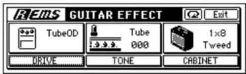
○ Bass type
Uses insert effect [I071 EB1: BassTubeComp]
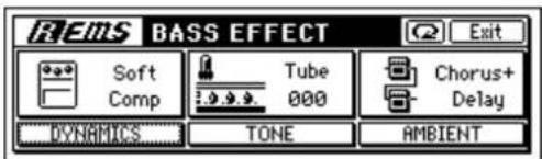
○ Mic type
Uses insert effect [I074 MS1: MicSimVox87]
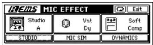
Appendix
Troubleshooting
Nothing appears in the display
□ Is the power of the D1200 turned off? (→p.15)
□ Is the contrast adjusted correctly? (→p.16)
No sound
☐ Is the power of the D1200 or a connected device turned off? ( p.15)
□ Have the [MASTER] fader or [PHONES] knob been lowered?
□ Has the channel volume level been lowered? If you have been using pairing and then switch pairing off, or if you have recalled a scene, the actual volume level may not match the physical position of the fader.
→ Move the fader up or down so that the fader matches the actual volume level, and then adjust the fader to an appropriate level.
Can't hear the playback
□ Is [TRACK STATUS] set to PLAY? (→p.8)
□ Cue, TrackMonitor, and CDMonitor are not output from the [MASTER OUT] jacks.
→ Either connect your monitoring system to the [MONITOR OUT] jacks, or listen through headphones.
□ Has solo been turned on, so that other tracks are not heard? (→p.39)
☐ When using auto punch-in/out, and you are unable to hear the playback of the recording track ([TRACK STATUS] REC) outside the IN-OUT region, you may have set the [INPUT/OUTPUT/SOLO] "Monitor" tab page "AutoIn" parameter to "On." (→p.54, 100)
☐ If you have selected Cue, the cue level of each channel may have been lowered.
→ In the [INPUT/OUTPUT/SOLO] "Monitor" tab page, press "Level" button, then raise the cue levels. (→p.38, 100)
Can't hear the input sound
□ After connecting your audio source to an input jack, did you assign it to a mixer channel?
→ In the [INPUT/OUTPUT/SOLO] "Ch1-6" or "Ch7-12" tab page, assign the source to a mixer channel. (→p.35)
□ Make sure that audio is being input.
→ In the [METER/TRACK VIEW] page, set "Select DisplayMode" to "PreFaderLev," and watch the meters to verify that audio is being input to each mixer channel. If the meters do not move, audio is not being input to the channels.
□ Are the monitor settings appropriate?
- In the [INPUT/OUTPUT/SOLO] "Monitor" tab page, select the signal that you want to monitor (normally, turn "MasterLR" "On").
If you have turned "Rhythm" or "Cue" "On," raise their volume levels. (→p.38, 100)
□ Is [TRACK STATUS] set to REC or INPUT? (→p.8)
□ Is the [TRIM] knob raised to an appropriate level?
☐ If the input sound cannot be heard when you play back a track whose [TRACK STATUS] is REC, did you turn the [INPUT/OUTPUT/SOLO] "Monitor" tab page "Autoln" setting "Off"? (→p.100)
☐ If cue is selected, the cue level of each channel may have been lowered.
→ In the [INPUT/OUTPUT/SOLO] "Monitor" tab page, press the "Level" button and raise the level. (→p.39)
☐ The digital input may become inaudible for two or three seconds. If the sampling frequency of the digital input source device changes while it is connected (e.g., 48 kHz → 44.1 kHz), it will take the sampling rate converter of the D1200 two or three seconds to lock to that frequency. Please wait until you hear sound.
☐ The format of the digital input source may be incorrect.
→ Connect an instrument or digital audio device that is CP-1201 or S/P DIF compliant.
Can't hear an audio CD inserted in the CDRW-1
□ Is the output of the internal CD-R/RW drive assigned to a mixer channel?
→ In the [INPUT/OUTPUT/SOLO] "Ch1-6" or "Ch7-12" tab page, assign the internal CD-R/RW drive to a mixer channel, and set [TRACK STATUS] to INPUT (orange).
☐ The "CD Monitor" sound is not output from the [MASTER OUT] jacks.
→ Connect your speaker system to the [MONITOR OUT] jacks, or listen through headphones.
□ Is the CD-R/RW drive installed correctly?
→ Refer to the installation instructions, and verify that that the drive is installed correctly. (→p.149)
Can't hear sound other than the audio CD
☐ "CD Monitor" may be turned "On," so that other sounds cannot be heard.
→ If "CD Monitor" is "On," all sounds other than from the CDRW-1 will be muted. Turn this "Off" unless you want to use the CDRW-1 to hear an audio CD. (→ p.94)
No sound from [AUX OUT]
"Can't apply external effect ([AUX OUT])" (→p.145)
Can't hear rhythm sound
(→p.145)
Can't hear scrub playback
☐ The incorrect track may be selected in the scrub page.
→ Select the correct track.
Channel fader or EQ does not work
Fader does not work
☐ During playback, the channel faders whose [TRACK STATUS] is REC are used to adjust the input level; the playback level is fixed at unity.
→ If you set [TRACK STATUS] to PLAY, you will be able to adjust the playback level.
☐ When pairing is on, the even-numbered faders of channels 1–6 will not function.
The audio level of paired channels is controlled by the fader of the odd-numbered channel at the left.
☐ If you switch pairing off after channels were paired, or if you recall a scene, the audio level of a channel may not match the position of the fader.
→ Raise or lower the fader so that it matches the actual volume level.
EQ does not work
☐ The input can be adjusted by the Input EQ; the Channel EQ will not affect the input.
→ Adjust the input EQ in the [INPUT/OUTPUT/SOLO] "InEq1-4" tab page.
☐ The playback can be adjusted by the Channel EQ; the Input EQ will not affect the playback.
→ Adjust the channel EQ in the [EQ] "Eq1–4," "Eq5–8," or "Eq9–12" tab page.
☐ The Input EQ cannot be applied to the digital input or rhythm. Input EQ can be used only on the analog input.
Can't record
☐ The D1200's [CHANNEL] fader may be lowered. (When the [BOUNCE] "RecMode" tab page "SelectRecMode" setting is at "Input.")
☐ The D1200's [MASTER] fader may be lowered.
(When the [BOUNCE] "RecMode" tab page "SelectRecMode" setting is at "Bounce.")
☐ Is [TRACK STATUS] set to REC for the recording-destination track?
□ Is there enough space on the drive?
→ Set the counter display to "FreeTime," and check the available recording time. (→p.32, 84)
→ Increase the free space on the song drive by deleting unwanted songs or songs you have already backed up.
(→p.68, 102)
☐ Is the input source you want to record assigned to a mixer channel?
→ In the [INPUT/OUTPUT/SOLO] "Ch1-6" or "Ch7-12" tab page, assign the input source to a mixer channel. (→p.35)
☐ Is the recording mode ("Select RecMode") appropriate? ( p.53, 92)
Can't use digital input
☐ If you want to use digital input, go to the [INPUT/OUTPUT/SOLO] "Ch1-6" or "Ch7-12" tab page and turn the "DigiIn" button "On," and assign the digital input to the input of the desired channel. (→p.37)
□ Is the sampling rate of the digital input supported?
→ Sampling rates of 96 kHz are not supported.
The input or recorded sound is noisy or distorted
☐ Is the [TRIM] knob set appropriately? The sound will be distorted if [TRIM] is set too high, and noisy if it is set too low.
→ In the [METER/TRACK VIEW] page set "Select Display-Mode" to "PreFaderLev," and adjust the [TRIM] knobs of the [INPUT 1/GUITAR IN]-[INPUT 4] jacks as high as possible without allowing the level meter to reach the "CLP" indicator.
☐ If the effect input or output is still distorted, make the following adjustments.
→ Input
- Insert effect: While you watch the meters in the [INSERT EFFECT] "InsEff1"–"Ins5–8" tab page, use the [TRIM] knob to adjust the input volume so that "CLIP" does not light.
- Master effect: While you watch the meters in the [MASTER EFFECT/AUX SEND] "EffSnd1" or "EffSnd2" tab page, adjust the send volume so that "CLIP" does not light.
- Final effect: While you watch the meters in the [FINAL EFFECT] "FinalEff" tab page, adjust the volume of each channel so that "CLP" does not light.
→ Output
- Insert effect: Adjust the effect parameters or [TRIM], and listen for any distortion.
- Master/final effect: While you watch the meters in the [MASTER EFFECT/AUX SEND] "EffSne1," "EffSnd2," or "FinalEff" tab page, adjust the effect parameters so that "CLP" does not light.
☐ If EQ causes distortion, make the following adjustments.
→ Adjust the gain of the input EQ for an analog input, or adjust the gain of the channel EQ for playback. (→p.38)
Effects do not apply
☐ You may have selected effect program number 00.
→ Set "EffectNumber" to other than "000" (=NO EFFECT).
Insert effects do not apply
□ Digital input may be enabled.
→ Insert effects cannot be used if "DigiIn" is turned "On" in the [INPUT/OUTPUT/SOLO] "Ch1-6" or "Ch7-12" tab page. Turn this setting "Off."
□ Is the effect inserted at the appropriate location?
→ In the [INSERT EFFECT] "InsAss" tab page, set "Assign" to "In" if you want to apply the effect to the input sound, or to "Trk" if you want to apply the effect to the play-back. (→p.42, 85)
Can't use the expression pedal or MIDI to control an insert effect
☐ In the [SYSTEM/USB] "Control" tab page, has a valid effect been selected for "Ass(#)"?
→ Make sure that a valid effect is selected for "Select-EffType" in the [INSERT EFFECT] "InsAss" tab page. Example: "Ass(#) " may have been set to "InsEff3" even though "SelectEffType" is set to "1in2out x2" (in which case only InsEff1 and InsEff2 can be used).
□ Are you using the correct device for control?
→ Use the device that is selected for "Device" in the [SYSTEM/USB] "Control" tab page. (→p.101)
□ Have you selected effect program number "000" (=NO EFFECT), or have you selected an effect program that does not include a control function?
☐ If you are using MIDI to control the effect, are the D1200 and the transmitting MIDI device set to the same MIDI channel? (→p.79, 101)
Can't select insert effect "1in2out x2"
☐ Insert effect assign may be set to "Trk."
→ You can select "1in2out x2" if [INSERT EFFECT] "In-sAss" tab page "Assign" is set to "In." Change the setting to "In."
Can't select insert effect "1in1out x8"
☐ Insert effect assign may be set to "In."
→ You can select "1in1out x 8" if [INSERT EFFECT] "In-sAss" tab page "Assign" is set to "Trk." Change the setting to "Trk."
Can't apply master effects
☐ The send level from each channel may be at zero or nearly zero.
→ In the [MASTER EFFECT/AUX SEND] "EffSnd1" or "EffSnd2" tab page, adjust "Send" to raise the send level.
☐ The return level may be at zero or nearly zero.
→ In the [MASTER EFFECT/AUX SEND] "MstEff1" or "MstEff2" tab page, adjust "RetLev" to raise the return level.
☐ If you are monitoring the sound from the [MONITOR OUT L/R] jacks, the monitor LR bus output may be turned off.
→ In the [INPUT/OUTPUT/SOLO] "Monitor" tab page, press the "MasterLR" button to turn it "On."
Can't apply the final effect
☐ If you are monitoring the sound from the [MONITOR OUT L/R] jacks, the master LR bus output may be turned off.
→ In the [INPUT/OUTPUT/SOLO] "Monitor" tab page, press the "MasterLR" button to turn it "On."
Can't apply external effect ([AUX OUT])
☐ The external send level may be at zero or nearly zero.
→ In the [MASTER EFFECT/AUX SEND] "AuxSend" tab page, use "AUX" to raise the external send level.
☐ Is the output of the external effect connect to the [INPUT 1]–[INPUT 4] jacks, and assigned to a mixer input?
→ Make the appropriate assignment in the [INPUT/OUTPUT/SOLO] "Ch1-6" or "Ch7-12" tab page.
☐ Have sub input settings been made correctly? (→p.67, 99)
Rhythm
Rhythm sound is not output
☐ In the [RHYTHM] "SetUp" tab page, "Rhythm" may be turned "Off." ([RHYTHM] key dark)
→ Turn "Rhythm" "On."
☐ The recorder may be stopped.
→ Press the [PLAY] key. The rhythm will sound when the recorder is recording or playing. If you want to check the rhythm while the recorder is stopped, access the [RHYTHM] "SetUp" tab page.
☐ You may have selected a silent rhythm pattern.
☐ The rhythm volume may be too low.
→ In the [RHYTHM] "SetUp" tab page, use "Rhythm Vol" to adjust the volume. If you are using tempo maps, use the "TmpMap" tab page "Edit" button to adjust the volume of each map.
Rhythm sound does not go away, or sounds in duplicate (excessive volume)
☐ In the [RHYTHM] "SetUp" tab page, "Rhythm" may be "On" ([RHYTHM] key lit).
→ Either change the "Rhythm" setting from "On" to "Off," or use "Vol" to lower the volume.
□ Rhythm may be selected for monitoring.
→ In the [INPUT/OUTPUT/SOLO] "Monitor" tab page, turn "Rhythm" "Off."
☐ Rhythm may be assigned as an input.
→ In the [INPUT/OUTPUT/SOLO] "Ch1-6" or "Ch7-12" tab page, either select a channel assignment other than "Rhythm L" or "Rhythm R," or turn "Rhythm" "Off" in the [RHYTHM] "SetUp" tab page.
A key does not function when pressed
☐ Some keys do not function while the recorder is playing or recording.
→ Stop the recorder, and then perform the operation.
☐ Some keys do not function while Scrub is on.
→ Turn off Scrub, and then perform the operation. (→ p.34, 124)
□ Is a dialog box open?
→ Press either the [YES/OK] key or the [NO/CANCEL] key to close the dialog box.
MIDI
MIDI sequencer won't synchronize/MIDI control is not possible
□ Are the MIDI cables connected correctly? (→p.14, 79)
□ A MIDI cable may be broken.
Can't synchronize using MTC or MIDI Clock
□ Are the master and slave settings correct? (→p.79)
□ Does the synchronization signal transmitted by the D1200 match the synchronization signal being received by your MIDI sequencer?
→ Check the "Select MIDI Sync Mode" setting. (→ p.79, 102)
☐ If "TempoSource" is set to "TempoTrack," has MIDI clock or tap tempo data been recorded on the tempo track? (→p.51)
□ Have the appropriate synchronization settings been made on your MIDI sequencer?
→ Refer to the owner's manual of your MIDI sequencer.
The D1200 won't receive MMC
☐ In the [SYSTEM/USB] "MIDI" tab page, is "RcvMMC" turned "On"?
☐ In the above page, is "MMC DevID" set to match the MMC device ID setting of your MIDI sequencer? (→ p.79, 102)
note For some MIDI sequencers, the MMC device ID setting may differ.
□ Is your MIDI sequencer set to transmit MMC?
→ Refer to the owner's manual of your MIDI sequencer.
Can't use MIDI to control effects or scenes
□ Are the D1200 and your MIDI sequencer set to the same MIDI channel?
→ In the [SYSTEM/USB] "MIDI" tab page, check the "GlobalCh." (→p.79, 101)
The D1200 does not synchronize as a slave
→ If the D1200 is set as an MTC slave, it may take several seconds for synchronization to occur.
Can't control another device via MMC
☐ In the [SYSTEM/USB] "MMC" tab page, is "Select MMC Mode" set to "Transmit"?
□ Is the MMC slave device set so that it will receive MMC?
The D1200 does not transmit mixer parameters
☐ In the [SYSTEM/USB] "MIDI" tab page, is "Control-Change" "Trans" turned "On"?
☐ Is the device receiving the control changes set to record each MIDI channel 1–12?
The D1200 does not receive mixer parameters
☐ In the [SYSTEM/USB] "MIDI" tab page, is "Control-Change" "Recv" turned "On"?
CD-R/RW
CD-R/RW drive option is not recognized
☐ Is the CD-R/RW drive option installed correctly?
→ Turn off the power of the D1200, and check the connections. (→p.150)
Can't write
☐ No further data can be written to a CD-R/RW disc that has been finalized. ( p.65, 76)
☐ No data can be written to a CD-RW disc that contains data written by another device.
□ Failed while writing to CD
→ Select a slower writing speed.
→ Use media that is recommended for your drive.
☐ Some writing speeds cannot be selected when writing a CD.
→ The speeds that you can select will depend on the type of media and on the specifications of the CDRW-1. (→ p.93)
Can't play back on an audio CD player
□ Did you finalize the disc?
→ In the [CD] "CD-R/RW" tab page, press the "Final" button to finalize the disc. (→p.65)
□ Did you use CD-R media?
→ Some CD players are unable to play back CD-RW media. We recommend that you use CD-R media.
□ Have you tried using a different type of media?
→ Even when the recommended media is used, some CD players are unable to play back certain types of CD-R media. You may be able to play back successfully if you use a different type of CD-R media.
Can't back up to CD-R/RW
□ Are you using blank media?
→ If using CD-R, you must use new (unused) media. If using CD-RW, go to the [CD] "CD-R/RW" tab page and use the "Erase" button to erase the media before you execute the backup operation.
WAV
Can't preview
□ Is the WAV file in a supported format?
→ Select a WAV file of a format that the D1200 supports, and preview it. (→p.71, 113)
USB
Computer does not recognize the D1200
☐ Is the USB cable connected correctly? ( p.15)
□ Is the D1200 set to USB mode? (→p.77)
Error occurred when you disconnected the D1200 from the computer
□ Use the correct procedure to disconnect. (→p.77)
When you connected the D1200, the computer asked you to install software or a device driver
☐ Does the operating system of your computer support the D1200? ( p.77)
Messages
Confirmation messages
Completed
☐ The operation was completed. Press the [YES/OK] key.
Song Full
☐ You have exceeded the maximum number of songs that can be stored on the drive.
→ Delete unneeded songs.
\*\*\*ing (\*\*\* is Copy, Write, etc.)
☐ The operation is being performed. Please wait until this display disappears.
Obey Copyright Rules
☐ When using digital input or when creating an audio CD, carefully read "COPYRIGHT WARNING" (→p.1) and observe the terms.
Error messages
▲ INIT Internal Hard Disk Drive
☐ The data stored on the hard disk and used to start up the D1200 has been damaged for some reason.
→ When you press the [YES/OK] key, all data will be erased from the hard disk and the disk will be initialized so that the D1200 can start up correctly. However, all data on the hard disk will be lost. When you turn off the power, do so using the correct procedure. (→p.15)
AE Timeout
☐ Check the connections of the CD-R/RW drive and the AC/DC power supply.
→ If there are no problems with the connections, it is possible that a malfunction has occurred.
Blank Disc
□ Nothing has been written on the CD media.
Can't Play CD
☐ The audio CD could not be played.
→ If the CD has not been finalized, finalize the CD before you attempt to play it.
→ If the CD has already been finalized, check the connections of the drive. If you find no problem with the connections or operation, try using different media.
Disc Full
□ When writing an audio CD, the CD has insufficient space.
→ Write to new CD media.
Disk Error
□ Failed while writing to the disk drive.
→ Execute "CheckDrive" in the [SYSTEM/USB] "DiskUtil" tab page. If this message still appears, delete that
song. If the message still appears, turn "Quick" to off, then re-format the drive.
It will take certain time for processing to be completed if you execute "CheckDrive" (when full) or "Format" on the hard disk drive.
Disk Busy
☐ As you perform punch-in/out recording or track editing operations, the audio data on the disk may become fragmented, causing disk access to slow down.
→ In the [TRACK] "EditTrk" tab page, execute the "OptimizeTrack" command. If this error still appears after you have executed "OptimizeTrack," execute the "CheckDrive" command.
In a studio or similar location, vibration due to ultra-low frequencies may cause "DiskBusy" to occur. If this is the cause of the error message, you can solve the problem by moving the D1200 to a different location, rather than executing the Check Drive operation.
Note If "DiskBusy" appears during playback, select "CurSong" when executing the "CheckDrive" command. If it appears during recording, select "CurSong+Remain." If you do not mind taking a substantial amount of time for the operation, execute "Full."
Disk Repaired 1
Disk Repaired 2
Disk Repaired 3
☐ An error was found by the "CheckDrive" command.
→ Disk Repaired 1 indicates that an error was found but was successfully repaired. You can continue using the drive.
Disk Repaired 2 or 3 indicate that it was not possible to completely correct the error. In this case, it is possible that the song data has been damaged or lost. In this case, the song data will be erased, but the drive will be usable once you initialize it.
Drive Condition Error
☐ This message may appear if you attempt to play a CD that has not been finalized.
→ Finalize the CD before you play it.
☐ If this message appears when you are operating the CD-R/RW drive, an error has occurred in the drive.
→ Check the drive connections. If you do not find a problem with the connections or operation, try using different media.
Drive Full
☐ The drive has no more free space.
- Turn the power off, and then on again. (If you have been recording or performing track editing, the immediately previous data will be saved on the drive.) If the message still appears, delete unwanted songs or select another drive.
Illegal Disc
□ Appropriate CD media was not inserted when you attempted to execute the operation.
Illegal Drive/Operation
☐ The operation you attempted to execute was not appropriate for the selected drive. For example this will appear if you attempt to load the system from a drive that does not contain the system.
→ Select the appropriate drive or operation.
Illegal Fat Number
☐ Some of the data on the hard disk has been damaged for some reason.
→ Erase all songs that cause this message to appear. If this message still appears, format the hard disk. (→p.75) When you turn off the power, do so using the correct procedure. (→p.15)
Illegal Mark Point
☐ When you use Disc At Once to write an audio CD, you must leave at least four seconds between marks.
→ There must also be an interval at least four seconds for the following.
• From the beginning of the track to the first mark.
- From the last mark before the end of the track being written to the CD, to the end time of the track.
Illegal To-End Time
☐ When using the track editing command "Exp/CompTrack," the TO and END points specify a region that cannot be executed relative to the IN-OUT region.
→ Set the TO-END region so that it is within 50–200% of the IN-OUT region.
InTime >= OutTime
☐ The operation cannot be executed because there is a mistake in the IN and OUT settings you made for track editing, auto punch-in/out, or loop. This will appear if IN is later than OUT, or if they are at the same time.
→ Set the IN and OUT times correctly.
Memory Full
☐ There is not enough memory for recording or track editing.
→ Delete unneeded data. Alternatively, you may be able to obtain more free memory by turning the power off and then on again.
MIDI Overflow
☐ A MIDI reception failure occurred while receiving MMC or while recording MIDI clock.
→ Set the transmitting device so that it will not transmit unnecessary data.
No CDRW Disc
☐ The media being erased is not CD-RW.
→ Execute the erase command on CD-RW media.
No Disc
□ CD media is not inserted.
No Drive/No Disk
→ "AE Timeout"
No Event
☐ When writing an audio CD, the selected track contained no audio data.
→ Either bounce the audio data to the selected track, or select another track.
No internal hard disk drive
→ "AE Timeout"
Nothing Changed
☐ Processing was executed, but no change occurred as a result.
Number Of Tracks
☐ During track editing, the edit-source and edit-destination contain a different number of tracks.
→ Make settings so that the number of tracks is the same.
□ Copy is not possible because "Clip" contains no data.
→ Either copy data to "Clip," or select a different copy-source track.
Path Length Overflow
□ Access was not possible because the folder level is too deep.
→ The D1200 cannot access a path that exceeds 64 characters. Do not create a folder level that exceeds 64 characters.
SameFileNameExists!
☐ When exporting a WAV file or backing up to the USB drive, an identically-named WAV file exists on the export-destination drive.
→ Change the file name.
Song Protected
☐ The selected song is protected.
→ Either turn protect off (→p.35), or select a different song.
→ When formatting, turn the "Force" button "On." (→p.75)
System Error
→ "AE Timeout"
Tempo Fast
☐ When recording tempo, recording failed because the tempo was too fast.
→ If you are recording MIDI clock, slow down the tempo of your sequencer or other MIDI output device.
→ If you are recording tap tempo, tap a little slower.
Tempo Slow
☐ When recording tempo, recording failed because the tempo was too slow.
→ If you are recording MIDI clock, set the tempo of your sequencer or other MIDI output device to ♩=40 or higher.
→ If you are recording tap tempo, tap a little faster.
ToTime >= EndTime
☐ The operation cannot be executed because there is a mistake in the TO and END settings you made for the "Exp/CompTrack" track editing command. This will appear if TO is later than END, or if they are at the same time.
→ Change the TO and END time to the correct settings.
Track Full
☐ When writing an audio CD, the number of tracks (songs) exceeded 99.
→ Write to new CD media.
Unsupported File Type!
☐ When importing a WAV file, you attempted to import a file that was not in 8-bit/16-bit/24-bit, 44.1 kHz, monaural/stereo format.
→ Select a 8-bit/16-bit/24-bit, 44.1 kHz, monaural/stereo format file.
Write CD Failed!
□ Failed while writing to CD.
→ Lower the speed at which you are attempting to write to the CD-R/RW.
→ Use media that is recommended for your drive.
→ Refer to the "CD-RW" section of "Troubleshooting."
About the CDRW-1
You can use the CDRW-1 CD-R/RW drive option to do the following things.
- Use the CDRW-1 to backup and restore.
- Use the CDRW-1 to create audio CDs.
- Insert an audio CD into the CDRW-1, assign its output to a mixer channel, and record or play the sound of the audio CD.
- Export WAV files to a CD-R/RW.
- Update the system from a CD-ROM/R/RW.
Never use any internal CD-R/RW drive other than the CDRW-1.
1. Cautions for handling
- During operation, use the unit in a horizontal position.
- Do not use the unit in extremely cold or hot locations.
- Do not use the unit in extremely humid locations.
- Do not use the unit in dusty or smoky locations.
- Do not subject the unit to vibration or strong physical shock. In particular, this unit is vulnerable to shock during operation (both during reading and writing).
- Normally, the drive uses software ejection, so you will be able to open the CD tray by pressing the eject button. However if this fails, you can forcibly eject the tray by inserting a thin object (such as a straightened paper clip) into the emergency eject hole.
- Do not store the unit in hot or humid locations.
- Never touch the focusing lens.
- Do not use commercially available lens cleaners.
- Do not transport the unit with a disc left in the tray.
- Do not leave the unit with the disc tray open.
CD-R/RW handling
Please observe the following points when handling discs. Failure to observe these points may cause problems such as data not being written correctly, loss of recorded data, or drive malfunction.
- Do not leave discs in direct sunlight, or in locations of high temperature or high humidity.
- Do not touch the surface of a disc. Hold a disc by its edges.
- Remove dust or dirt from the surface of a disc. To remove dust, use an air duster or cleaner.
- Do not affix labels to a disc, or write on a disc in locations other than specified.
- Do not use chemicals or detergent to wipe a disc.
- Do not bend or drop a disc.
Responsibility for loss of data
Korg Corporation will accept no responsibility for any damages (direct or indirect, whether sustained by the customer or by a third party) resulting from loss of or damage to data written on a CD-R or CD-RW disc using the CDRW-1.
2. Installing the CDRW-1
Before installing the CDRW-1, you must turn off the power of the D1200 and unplug the AC/DC power supply.
① Remove the cover.
Slide the [EJECT] switch (located on the bottom of the D1200) in the direction of the arrow, and the drive bay cover of the D1200 will be pushed out.
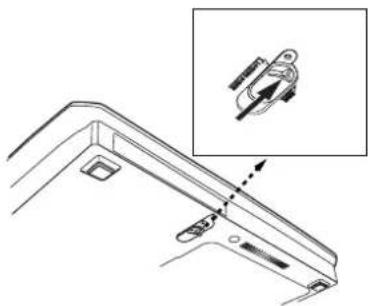
natural_image
Technical line drawing of a mechanical bracket with an inset showing a close-up of a component (no text or symbols)② Remove the cover.
Catch the edge of the cover that was pushed out, and remove it in the direction shown by the arrow in the diagram.
The cover may be damaged if you forcibly pull it toward yourself.
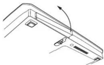
natural_image
Technical line drawing of a mechanical bracket or support structure with mounting holes and a curved arrow indicating rotation (no text or symbols)Note Keep the cover you removed in a safe place, since you will need it if you remove the CDRW-1.
③ Insert the CDRW-1.
Push the CDRW-1 into the D1200's drive bay until the front panel of the CDRW-1 is aligned with the side panel of the D1200. Make sure that the drive is oriented in the correct direction when you insert it into the D1200.
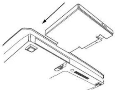
natural_image
Technical line drawing of a mechanical bracket assembly (no text or symbols)Press in the direction indicated by the arrow until you hear the internal connector click into place.
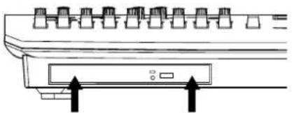
natural_image
Diagram of a server rack with ports and an open control panel (no text or symbols)Press equally on both sides.
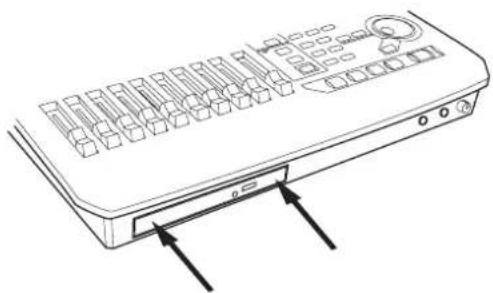
natural_image
Line drawing of a remote control device with buttons and a keypad (no text or symbols)④ Check the installation.
Turn on the power of the D1200, and verify that the CDRW-1 is detected in the startup LCD screen.
If the CDRW-1 was detected
KORG Version 1.00
D1200
Digital Recording Studio
If the CDRW-1 was not detected
KORC Version 1.00
D1200
Digital Recording Studio
CD-RW installable
If the D1200 does not detect the D1200, try pressing strongly once again on the areas indicated by the arrows in step ③, or re-install the CDRW-1.
To remove the CDRW-1
Slice the [EJECT] switch located on the bottom panel of the D1200, and the CDRW-1 will be ejected from the D1200. Gently pull out the ejected CDRW-1.
This procedure must be performed with the power off.
To fasten the CDRW-1 in place
By using the screw that is included with the CDRW-1, you can lock the [EJECT] switch of the D1200 to ensure that the CDRW-1 does not come out accidentally.
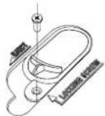
3. Inserting a disc
Make sure that the D1200 is powered-on.
① Open the disc tray.
Press the eject button of the CDRW-1 to open the disc tray.
At this time the tray will only open halfway. Manually pull out the tray far enough that the disc can be placed on the tray.
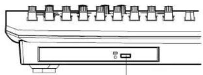
natural_image
Technical line drawing of a mechanical component with no visible text or symbolsEject button
When you use the CDRW-1 for the first time, remove the pickup stopper from the disc tray before using the drive.
② Place the disc on the tray.
Place the disc accurately on the tray with the label facing upward.
③ Close the disc tray.
Push the disk tray in until it is completely closed.
If the D1200 does not recognize the disc, re-install the CDRW-1 as described in "Installing the CDRW-1."
4. Removing a disc
① Press the eject button to open the disc tray.
② Gently remove the disc from the disc tray.
③ Push the disc tray in until it is completely closed.
Emergency disc removal
Normally you will be able to remove the disc as described above. However if this is not possible due to a power failure or other problem, you can also remove the disc as follows.
To use this method, you will need a pin-like object of less than 2 mm diameter, such as a straightened paper clip. Insert this straight into the manual eject hole, and push. The disc tray will be forced open.
Excessive use of this method may cause the CDRW-1 to malfunction.
This procedure must be performed with the power off.
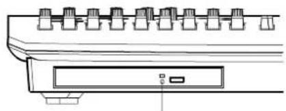
natural_image
Technical line drawing of a mechanical component with multiple ports and a central button (no text or symbols)Manual eject hole
5. Using the CDRW-1
For details on how to back up and restore using the CDRW-1, and how to use the CDRW-1 to create an audio CD, refer to "Operation."
When using the CDRW-1, you must operate the unit in a level position in a location that is not subject to vibration.
Playing back an audio CD
Here's how to play back an audio CD and listen to it through your headphones or monitor speakers.
① Connect headphones to the [PHONES] jack or monitor speakers to the [MONITOR OUT L/R] jacks, and turn down the level knobs for each jack to the minimum volume.
② Insert an audio CD in the CDRW-1.
Press the eject button of the CDRW-1, open the disc tray, and insert the audio CD.
③ Play back the audio CD.
Access the [CD] "CDR/RW" tab page. Use the cursor to select the CDR-RW transport key, and press the [ENTER] key.
④ Press the "CD Monitor" button, and gradually raise the [PHONES] or [MONITOR OUT L/R] volume level.
Recording the sound of an audio CD
Here's how to assign the L channel of an audio CD to track 1, the R channel to track 2, and record the sound of the CD.
① Insert an audio CD in the CDRW-1.
② Assign the audio output from the CDRW-1 to tracks 1 and 2.
Access the [INPUT/OUTPUT/SOLO] "Ch1-6" tab page, select the "Ch1" icon, and use the [VALUE] dial to select "CD L." In the same way, select the "Ch2" icon and select "CD R."
③ Specify the recording tracks.
Press the [TRACK STATUS] keys of tracks 1 and 2 to select REC.
④ Check the recording mode.
Access the [BOUNCE] "RecMode" tab page. Set "SelectRecMode" to "Input."
⑤ Press the [REC] key to enter record-ready mode.
⑥ Play back the audio CD.
Access the [CD] "CDR/RW" tab page. Use the cursor to select the CD-R/RW transport key, and press the [ENTER] key.
⑦ Press the [PLAY] key to begin recording.
⑧ When you are finished recording, press the [STOP] key.
⑨ Stop the audio CD.
Access the [CD] "CDR/RW" tab page. Move the cursor to the CD-R/RW transport key, and press the [ENTER] key.
⑩ Play back the song, and verify that it was recorded correctly.
The beginning of recording on the D1200 is not synchronized with the beginning of playback of the CD in the CDRW-1. This means that the above method cannot be used to record the very beginning of the audio CD. If you want to record from the beginning of a song, make Trigger settings before step ④ of this procedure. (-p.54)
D1200 specifications
Operating temperature +5 - +35 °C (do not allow condensation)
■ Specifications
Number of tracks: 96 tracks (including virtual tracks)
12 tracks simultaneous playback, 4 tracks simultaneous recording @ 16-bit
6 tracks simultaneous playback, 4 tracks simultaneous recording @ 24-bit
Recording format: 24-bit/16-bit uncompressed, 44.1 kHz
Recording time: 16-bit recording: maximum 122 hours
24-bit recording: maximum 61 hot
Storage capacity: 40 GB hard disk (2 GB is reserved for use with a USB drive)
Number of songs: 100 songs per drive
Length of one song: Max. 12 hours Counter display (MSM): "720:000.000"
Locate points: Four points per song
Mark points: 100 points per song (marks can be named)
Metronome 96
patterns:
Rhythm patterns: 215
MMC functions: Transmitted and received
Synchronization: MTC transmission/reception, MIDI Clock
transmission
Tempo map (200 events per song)
Sync track (one track per song) Tempo recording
CD-R/RW Create audio CD (Disc At Once/Track At
functions: Once), backup/restore, export/import WAV file (ISO9660)
USB functions: Backup/restore (FAT 16), WAV file import (FAT 16)/export (FAT 16)
Track editing: Copy (tracks can be copied between songs), insert, erase, delete, swap, reverse, time expansion/compression, fade, normalize, optimize
Song editing: Copy, move, delete, rename, protect
Counter/locate Min/Sec/mSec, Meas/Beat/Tick, Min/
format: Sec/Frame (30 NDF only)
MIDI functionality: Mixer control, effect control, MMC
transmission/reception, MTC
transmission/reception, MIDI Clock
transmission
Structure: 16 channel input, 4 bus, 1 AUX, 1 master
Signal processing: 32-bit, 44.1 kHz
Equalizer: HIGH (f: 10 kHz G:±15 dB)
MID (f: 0.1–20 kHz G:±15 dB)
LOW (f: 100 Hz G: ±15 dB)
Scene memories: 100 scene per song
Structure: Insert · 8 (maximum)
Master · 2 (maximum)
Final·1
All usable simultaneously
Signal processing: 44-bit 44.1 kHz
Programs: Insert (128 preset, 128 user)
Master (32 preset, 32 user)
Final (32 preset, 32 user)
Algorithms: 98
Effects: 106
Display: 240 · 64 pixel LCD with backlight
Power supply: Included AC/DC power supply
Power 19 W (D1200 only)
consumption: 23 W (with CDRW-1 installed)
Dimensions: 400 mm (W) · 268 mm (D) · 77 mm (H)
(including protrusions)
Weight: 2.9 kg/6.39 lbs (D1200 only)
3.3 kg/7.28 lbs (with CDRW-1 installed)
■ Principal specifications
Frequency response:10 Hz - 20 kHz ±1 dB @ +4 dBu, 10 kΩ load
S/N: 95 dB (typical) @ IHF-A
Dynamic range: 95 dB (typical) @ IHF-A
THD_N: 0.02% (typical) 20 Hz-20 kHz @+16 dBu,10
kΩ load
A/D conversion: 24-bit 64 times oversampling
D/A conversion: 24-bit 128 times oversampling
Sampling 44.1 kHz
frequency:
■ Analog/digital input and output specifications
Connectors: XLR-3-31 type (+48 V phantom power, switchable), 1/4" TRS phone jack (balanced)
Input impedance: 5 kΩ (XLR-3-31), 22 kΩ (TRS phone jacks)
Nominal level: -60 dBu @ TRIM=max.
+4 dBu @ TRIM=min.
Maximum level: -48 dBu @ TRIM=max.
+16 dBu @ TRIM=min.
Source impedance: 600 Ω
Connectors: 1/4" TRS phone jack (balanced)
Input impedance: 22 kΩ
Nominal level: -60 dBu @ TRIM=max.
+4 dBu @ TRIM=min.
Maximum level: -48 dBu @ TRIM=max.
+16 dBu @ TRIM=min.
Source impedance: 600 Ω
Connector: 1/4" phone jack (unbalanced)
Input impedance: 1 MΩ
Nominal level: -60 dBu @ TRIM=max.
+4 dBu @ TRIM=min.
Maximum level: -48 dBu @ TRIM=max.
+16 dBu @ TRIM=min.
Source impedance: 600 Ω
Connectors: RCA phono jack (unbalanced)
Output impedance: 150 Ω
Nominal level: -10 dBu
Maximum level: +2 dBu
Load impedance: 10 kΩ or higher
Connectors: RCA phono jack (unbalanced)
Output impedance: 150 Ω
Nominal level: -10 dBu
Maximum level: +2 dBu
Load impedance: 10 kΩ or higher
Connectors: 1/4" phone jack (unbalanced)
Output impedance: 150 Ω
Nominal level: -10 dBu
Maximum level: +2 dBu
Load impedance: 10 kΩ or higher
Connector: 1/4" stereo phone jack
Output impedance: 100 Ω
Maximum level: 50 mW @ 32 Ω
Connector: optical
Format: 24-bit S/P DIF (IEC60958, ELAJ CP-1201)
Connector: Type B
Format: Slave, USB 1.1 compliant
Supported OS: Window Me, Windows 2000 or later/Mac OS 9.0.4 or later
* If using the D1200 with Windows 98, please refer to the Korg website or contact your Korg distributor.
Connectors: DIN 5-pin · 2
Connector: 1/4" phone jack (use separately sold PS-1)
Connector: 1/4" stereo phone jack (use separately sold XVP-10 or EXP-2)
Connector: DIN 7-pin
■ Included items
AC/DC power supply
Owner's manual
■ Separately sold options
PS-1 pedal switch
XVP-10 EXP/VOL pedal
EXP-2 foot controller
CDRW-1 CD-R/RW drive (internal)
* Appearance and specifications of this product are subject to change without notice. (05, 2002)
Effect Program List
INSERT EFFECT Preset128 User128
| Engl | Categ | ProgramName | Algorithm | EFF1 Mode | |||||
| Reverb 7 | |||||||||
| 001 | RV1 Reverb Hall Reverb Hall HALL | ||||||||
| 002 | RV2 Smooth Hall Smooth Hall Smt Hall | ||||||||
| 003 | RV3 Wet Plate Reverb Wet Plate WPlate | ||||||||
| 004 | RV4 Dry Plate Reverb Dry Plate DPlate | ||||||||
| 005 | RV5 Reverb Room Reverb Room ROOM | ||||||||
| 006 | RV6 Bright Room Bright Room Br Room | ||||||||
| 007 | RV7 ER Early Reflection ER | ||||||||
| Delay 6 | |||||||||
| 008 | DL1 L/C/R Delay L/C/R Delay LCRDly | ||||||||
| 009 | DL2 St/X Delay St/Cross Delay StDly | ||||||||
| 010 | DL3 St.MtapDelay St.Multitap Delay MtDly | ||||||||
| 011 | DL4 St.ModDelay St.Modulation Delay ModDly | ||||||||
| 012 | DL5 St.DynaDelay St.Dynamic Delay DyDly | ||||||||
| 013 | DL6 AutoPanDelay St.Auto Panning Delay PanDly | ||||||||
| Modulation 7 | |||||||||
| 014 | M01 St.Chorus St.Chorus Chorus | ||||||||
| 015 | M02 St.Flanger St.Flanger Flangr | ||||||||
| 016 | M03 St.Phaser St.Phaser Phaser | ||||||||
| 017 | M04 St.Vibrato St.Vibrato Vibrat | ||||||||
| 018 | M05 St.Tremolo St.Tremolo StTrml | ||||||||
| 019 | M06 St.AutoPan St.Auto Pan AutPan | ||||||||
| 020 | M07 Ensemble Ensembl | ||||||||
| Dynamics 7 | |||||||||
| 021 | DY1 St.Comp St.Compressor StComp | ||||||||
| 022 | DY2 St.Limiter St.Limiter St.Lmit | ||||||||
| 023 | DY3 MBandLimiter Multiband Limiter BnLmit | ||||||||
| 024 | DY4 St.Gate St.Gate StGate | ||||||||
| 025 | DY5 St.Exciter St.Excitant/Enhancer StExctr | ||||||||
| 026 | DY6 St.Decimator St.Decimator Decim | ||||||||
| 027 | DY7 St.P4EQ St.Parametric 4band EQ P4EQ | ||||||||
| Special Effects 4 | |||||||||
| 028 | SE1 St.RingMod St.Ring Modulator RingMd | ||||||||
| 029 | SE2 Doppler Doppler Dopplr | ||||||||
| 030 | SE3 AnalogRecord St.Analog Record Record | ||||||||
| 031 | SE4 TalkingMod Talking Modulator TalkMd | ||||||||
| LargeSizeEffect7 | |||||||||
| 032 | LS1 St.G7EQ St.Graphic 7band EQ G7EQ | ||||||||
| 033 | LS2 St.MBLimiter St.Multiband Limiter SBnLmt | ||||||||
| 034 | LS3 Vocoder Vocoder Vocoder | ||||||||
| 035 | LS4 StPitchShift St.Pitch Shifter StPitch | ||||||||
| 036 | LS5 ER Large Early Reflections L ER-L | ||||||||
| 037 | LS6 RotarySpeaker Rotary Speaker RotSP | ||||||||
| 038 | LS7 Cntt Cancellir Center Cancellation Cancdr | ||||||||
| Guitar Multi 13 | EFF1 | EFF2 | EFF3 | EFF4 | EFF5 | ||||
| 039 | GT1 GuitarMulti1 Guitar Multi1 Dist NR Cho/FI S.Dly | ||||||||
| 040 | GT2 GuitarMulti2 Guitar Multi2 Wah Dist NR Delay | ||||||||
| 041 | GT3 GuitarMulti3 Guitar Multi3 Dist NR AmpSim CabRes Delay | ||||||||
| 042 | GT4 GuitarMulti4 Guitar Multi4 Comp P4EQ AmpSim Cho/FI S.Dly | ||||||||
| 043 | GT5 GuitarMulti5 Guitar Multi5 Wah Comp P4EQ Cho/FI S.Dly | ||||||||
| 044 | GT6 GuitarMulti6 Guitar Multi6 Comp P4EQ Pitch Delay | ||||||||
| 045 | GT2 StackWah Guitar Multi2 Wah Dist NR Delay | ||||||||
| 046 | GT4 Clean Guitar Multi4 Comp P4EQ AmpSim Cho/FI S.Dly | ||||||||
| 047 | EB1 CleanChorus Bass Multi 1 Comp Extr P4EQ Cho/FI S.Dly | ||||||||
| 048 | GT5 HalfTone Guitar Multi5 Wah Comp P4EQ Cho/FI S.Dly | ||||||||
| 049 | GT6 Detune Guitar Multi6 Comp P4EQ Pitch Delay | ||||||||
| 050 | GT6 12string Sim Guitar Multi6 Comp P4EQ Pitch Delay | ||||||||
| Amp Simulator 4 | |||||||||
| 051 | AS1 Amp-Stack Amp Simulator1 NR AmpSim CabRes Cho/FI S.Dly | ||||||||
| 052 | AS2 Vox-Tremolo Amp Simulator2 NR AmpSim CabRes Treml Delay | ||||||||
| 053 | AS3 Amp-Phaser Amp Simulator3 NR AmpSim CabRes Phaser Delay | ||||||||
| 054 | AS1 Amp-SS Amp Simulator1 NR AmpSim CabRes Cho/FI S.Dly | ||||||||
| PreAmp Simulator 5 | |||||||||
| 055 | PA1 Brit 70's Pre Amp Simulator Drive NR2 Tone Cabinet | ||||||||
| 056 | PA1 Brit 80's Pre Amp Simulator Drive NR2 Tone Cabinet | ||||||||
| 057 | PA1 U.S 90's Pre Amp Simulator Drive NR2 Tone Cabinet | ||||||||
| 058 | PA1 LOUD 00'S Pre Amp Simulator Drive NR2 Tone Cabinet | ||||||||
| 059 | PA1 BLUES Pre Amp Simulator Drive NR2 Tone Cabinet | ||||||||
| 060 | PA1 STEVIE Pre Amp Simulator Drive NR2 Tone Cabinet | ||||||||
| 061 | PA1 SMALL TW Pre Amp Simulator Drive NR2 Tone Cabinet | ||||||||
| 062 | PA1 AC-15 Pre Amp Simulator Drive NR2 Tone Cabinet | ||||||||
| 063 | PA1 TWEED Pre Amp Simulator Drive NR2 Tone Cabinet | ||||||||
| 064 | PA1 AC-30TB Pre Amp Simulator Drive NR2 Tone Cabinet | ||||||||
| 065 | PA1 RECTO Pre Amp Simulator Drive NR2 Tone Cabinet | ||||||||
| 066 | PA1 CLASSIC DIST Pre Amp Simulator Drive NR2 Tone Cabinet | ||||||||
| 067 | PA1 FAT Pre Amp Simulator Drive NR2 Tone Cabinet | ||||||||
| 068 | PA1 ZONE Pre Amp Simulator Drive NR2 Tone Cabinet | ||||||||
| 069 | PA1 FUZZ 70's Pre Amp Simulator Drive NR2 Tone Cabinet | ||||||||
| ProgNo | Categ | ProgramName | Algorithm | EFF1 | EFF2 | EFF3 | EFF4 | EFF5 | Mode |
| Bass Multi 4 | |||||||||
| I070 | EB1 | Bass Multi1 | Bass Multi1 | CompT | Exctr | P4EQ | Cho/FI | S.Dly | |
| I071 | EB1 | BassTubeComp | Bass Multi1 | CompT | Exctr | P4EQ | Cho/FI | S.Dly | |
| I072 | EB2 | Bass Multi2 | Bass Multi2 | Dist | NR | Filter | Delay | S.Dly | |
| I073 | EB3 | Bass Multi3 | Bass Multi3 | Comp | P4EQ | Gate | |||
| Mic Multi 7 | |||||||||
| I074 | MS1 | MicSimVox87 | Mic Multi | Cabi | MicSim | Comp | |||
| I075 | MS1 | MicSimTube47 | Mic Multi | Cabi | MicSim | Comp | |||
| I076 | MS1 | MicSim451 | Mic Multi | Cabi | MicSim | Comp | |||
| I077 | MS1 | MicSim414 | Mic Multi | Cabi | MicSim | Comp | |||
| I078 | MS1 | MicSimLong20 | Mic Multi | Cabi | MicSim | Comp | |||
| I079 | MS1 | MicSim421 | Mic Multi | Cabi | MicSim | Comp | |||
| I080 | MS1 | MicSimScal55 | Mic Multi | Cabi | MicSim | Comp | |||
| Vocal Multi 4 | |||||||||
| I081 | VO1 | Vocal Multi1 | Vocal Multi1 | Comp | Exctr | Pitch | S.Dly | ||
| I082 | VO2 | Vocal Multi2 | Vocal Multi2 | NR | DeEss | P4EQ | Cho/FI | S.Dly | |
| I083 | EB1 | RockVocal | Bass Multi 1 | Comp | Exctr | P4EQ | Cho/FI | S.Dly | |
| I084 | EB1 | VocalDouble | Bass Multi 1 | Comp | Exctr | P4EQ | Cho/FI | S.Dly | |
| Mono-Mono 40 | EFF 1 EFF 2 | ||||||||
| I085 | MM1 | P4EQ-Exciter | P4EQ-Exciter | P4EQ | Excit1 | 1in1out x 4 | |||
| I086 | MM2 | P4EQ-Wah | P4EQ-Wah | P4EQ | Wah | ||||
| I087 | MM3 | P4EQ-Cho/Fln | P4EQ-Cho/Flng | P4EQ | ChFi1 | ||||
| I088 | MM4 | P4EQ-Phaser | P4EQ-Phaser | P4EQ | Phaser | ||||
| I089 | MM5 | P4EQ-MtDelay | P4EQ-Mt.Delay | P4EQ | Mt.Dly | ||||
| I090 | MM6 | Comp-Wah | Comp-Wah | Comp2 | Wah | ||||
| I091 | MM7 | Comp-AmpSim | Comp-AmpSim | Comp2 | AmpSim | ||||
| I092 | MM8 | Comp-OD/HiG | Comp-OD/HiG | Comp1 | ODHiG | ||||
| I093 | MM9 | Comp-P4EQ | Comp-P4EQ | Comp1 | P4EQ | ||||
| I094 | MM10 | Comp-Cho/Fl | Comp-Cho/Flng | Comp2 | ChFi1 | ||||
| I095 | MM11 | Comp-Phaser Comp | Comp-Phaser Comp2 | Phaser | |||||
| I096 | MM12 | Comp-MtDly | Comp-Mt.Delay | Comp2 | Mt.Dly | ||||
| I097 | MM13 | Exctr-Comp Exciter | Exctr-Comp Exciter2 | Comp1 | |||||
| I098 | MM14 | Exctr-Limtr | Exciter-Limiter | Excit2 | Limitr | ||||
| I099 | MM15 | Exctr-Ch/Fl Exciter | Exctr-Cho/Flng Excit2 ChF1 | ||||||
| I100 | MM16 | Exctr-Phasr | Exciter-Phaser | Excit2 | Phaser | ||||
| I101 | MM17 | Exctr-MtDly Exciter | Exctr-Mt.Delay Excit2 Mt.Dly | ||||||
| I102 | MM18 | Limitr-P4EQ | Limiter-P4EQ | Limitr | P4EQ | ||||
| I103 | MM19 | Limitr-Ch/Fl | Limiter-Cho/Flng | Limitr | ChFi2 | ||||
| I104 | MM20 | Limitr-Phasr | Limiter-Phaser | Limitr | Phaser | ||||
| I105 | MM21 | Limitr-MtDly | Limiter-Mt.Delay | Limitr | Mt.Dly | ||||
| I106 | MM22 | OD/HG-Ch/Fl | OD/HiG-Cho/Flng ODHiG ChFi1 | ||||||
| I107 | MM23 | OD/HG-Phasr | OD/HiG-Phaser | ODHiG | Phaser | ||||
| I108 | MM24 | OD/HG-MtDly OD/HiG-Mt.Delay ODHiG Mt.Dly | |||||||
| I109 | MM25 | OD/HG-AmpSim | OD/HiG-AmpSim | ODHiG | AmpSim | ||||
| I110 | MM26 | Wah-AmpSim | Wah-AmpSim | Wah | AmpSim | ||||
| I111 | MM27 | Deci-AmpSim | Decimator-AmpSim | Decima | AmpSim | ||||
| I112 | MM28 | Decima-Comp | Decimator-Comp | Decima | Comp1 | ||||
| I113 | MM29 | Ch/Fl-MtDly ChoFlng-Mt.Delay ChFl2 Mt.Dly | |||||||
| I114 | MM30 | Phasr-Ch/Fl | Phaser-Cho/Flng | Phaser | ChFl2 | ||||
| I115 | MM31 | Amp-Tremolo | AmpSim-Tremolo | AmpSim | Treml | ||||
| I116 | MM32 | Reverb-Gate | Reverb-Gate | Reverb | Gate | ||||
| I117 | MM33 | MicSim-Lmtr | MicSim-Limiter | MicSim | Limitr | ||||
| Mono-Mono 15 | EFF1 | ||||||||
| I118 | MN1 | OD/HiGain | OverDrive/HighGain | ODHiG | |||||
| I119 | MN2 | Compressor | Compressor2 | Comp2 | 1in1out x 8 | ||||
| I120 | MN3 | Limiter | Limiter | Limiter | |||||
| I121 | MN4 | Gate | Gate | Gate | |||||
| I122 | MN5 | Exciter | Exciter2 | Excit2 | |||||
| I123 | MN6 | P4EQ | Parametric 4band EQ P4EQ | ||||||
| I124 | MN7 | AmpSim Amp Simulator | AmpSim Mt.Dly | ||||||
| I125 | MN8 | Mt.Delay | Multitap Delay ChFI2 | ||||||
| I126 | MN9 | Cho/Flng | Chorus/Flanger | ||||||
| I127 | MN10 | Phaser | Phaser | ||||||
| I128 | MN11 | Expander | Expander | ||||||
MASTER EFFECT Preset32 User32
| ProgNo | Categ | ProgramName | Algorithm EFF 1 | |
| Reverb 15 | ||||
| M001 | RV1 | FeverbHall Reverb | Hall HALL | |
| M002 | RV2 | Smooth Hall | Smooth Hall | SmtHall |
| M003 | RV3 | WetPlate | Feverb Wet Plate | WPlate |
| M004 | RV4 | Dry Plate | Feverb Dry Plate DPlate | |
| M005 | RV5 | FeverbRoom | Feverb Room | FCOM |
| M006 | RV6 | BrightRoom | Bright Room | BrRoom |
| M007 | RV7 | ER | Early Reflections | ER |
| M008 | RV3 | Dark Plate | Feverb Wet Plate | WPlate |
| M009 | RV4 | BrightPlate | Feverb Dry Plate DPlate | |
| M010 | RV1 | AREMA | Feverb Hall HALL | |
| M011 | RV2 | Cathedral | Smooth Hall | SmtHall |
| M012 | RV5 | Club | Feverb Room | FCOM |
| M013 | RV6 | ListeningRoom | Bright Room | BrRoom |
| M014 | RV7 | NeoAcoustic | Early Reflections | ER |
| M015 | RV6 | Garage | Bright Room | BrRoom |
| Delay 6 | ||||
| M016 | DL1 | L/C/R Delay | L/C/R Delay | LCRDly |
| M017 | DL2 | StXDelay | St/Cross Delay | StDly |
| M018 | DL3 | St.MtapDelay | St.Multitap Delay | Midly |
| M019 | DL4 | St.ModDelay | St.Modulation Delay | ModDly |
| M020 | DL5 | St.DynaDelay | St.Dynamic Delay | DyDly |
| M021 | DL6 | AutoPanDelay | St.Auto Panning Delay | PanDly |
| Modulation 7 | ||||
| M022 | MO1 | St.Chorus | St.Chorus | Chorus |
| M023 | MO2 | St.Flanger | St.Flanger | Flangr |
| M024 | NO3 | St.Phaser | St.Phaser | Phaser |
| M025 | MO4 | St.Vibrato | St.Vibrato | Vibrat |
| M026 | MO5 | St.Tremolo | St.Tremolo | StTrml |
| M027 | MO6 | St.AutoPan | St.AutoPan | AutPan |
| M028 | MO7 | Ensemble | Ensemble | Ensmbl |
| Special Effects 4 | ||||
| M029 | SE1 | St.RingMod | St.Ring Modulator | RingMd |
| M030 | SE2 | Doppler | Doppler | Doppir |
| M031 | SE3 | AnalogRecord | St.Analog Record | Record |
| M032 | SE4 | TalkingMod | Talking Modulator | TalkMd |
FINAL EFFECT Preset32 User32
| ProgNo | Categ | ProgramName | Algorithm | EFF 1 |
| Dynamics 10 | ||||
| F001 | DY1 | St.Comp | St.Compressor | StComp |
| F002 | DY1 | StudioComp | St.Compressor | StComp |
| F003 | DY1 | TwoMix 60's | St.Compressor | StComp |
| F004 | DY1 | TwoMix 70's | St.Compressor | StComp |
| F005 | DY2 | St.Limiter | St.Limiter | StLimit |
| F006 | DY2 | ReMSTR POP | St.Limiter | StLimit |
| F007 | DY2 | ReMSTR DANCE | St.Limiter | StLimit |
| F008 | DY2 | StudioLimiter | St.Limiter | StLimit |
| F009 | DY4 | St.Gate | St.Gate | STgate |
| F010 | DY7 | St.P4EQ | St.Parametric 4band EQ | P4EQ |
| LargeSizeEffect 10 | ||||
| F011 | LS1 | St.G7EQ | St.Graphic 7band EQ | G7EQ |
| F012 | LS2 | St.MBLimiter | St.Multiband Limiter | SBNLmt |
| F013 | LS2 | ReMasterLA | St.Multiband Limiter | SBNLmt |
| F014 | LS2 | GrooveBeat | St.Multiband Limiter | SBNLmt |
| F015 | LS2 | TwoMixHipHop | St.Multiband Limiter | SBNLmt |
| F016 | LS2 | TwoMixDance | St.Multiband Limiter | SBNLmt |
| F017 | LS2 | 2MixGirlPop | St.Multiband Limiter | SBNLmt |
| F018 | LS2 | Digital Rock | St.Multiband Limiter | SBNLmt |
| F019 | LS2 | TwoMix 80's | St Multiband Limiter | SBNLmt |
| F020 | LS5 | ER_Large | Early Reflections L | ER-L |
| Reverb 6 | ||||
| F021 | RV1 | ReverbHall Reverb Hall HALL | ||
| F022 | RV2 | SmoothHall Smooth Hall | SmHall | |
| F023 | RV3 | WetPlate | Reverb Wet Plate | WPlate |
| F024 | RV4 | DryPlate | Reverb Dry Plate | DPlate |
| F025 | RV5 | ReverbRoom | Reverb Room | ROOM |
| F026 | RV6 | BrightRoom | Bright Room | BrRoom |
| Delay 6 | ||||
| F027 | DL1 LC/R Delay | LC/R Delay | LORDly | |
| F028 | DL2 StX.Delay | StCross Delay | StDly | |
| F029 | DL3 StMapDelay | StMultitap Delay | MDly | |
| F030 | DL4 StModDelay | StModulation Delay | ModDly | |
| F031 | DL5 StDynaDelay | StDynamic Delay | DyDly | |
| F032 | DL6 AutoPanDelay | St.Auto Panning Delay | PanDly | |
Rhythm Pattern List (215patterns)
For Beat settings other than 3/4, 4/4, and 6/8, only (Blank), Metro, and HiHat can be selected.
For Beat settings of 3/4, 4/4, and 6/8, the following rhythm patterns can be selected in addition to (Blank), Metro, and HiHat.
[I], [F], and [E] indicate Intro, Fill, and Ending patterns. The Length and Tempo values in this list are the number of measures in each rhythm, and the recommended tempo.
RhythmName Length Tempo
| ----3/4---- (13 pattern) | |
| 3/4 4 150 | |
| [I]3/4 7 150 | |
| [F]3/4 1 150 | |
| [E]3/4 4 150 | |
| JazzWaltz1 8 150 | |
| JazzWaltz2 8 150 | |
| [I]JazzWaltz 4 150 | |
| [F]JazzWaltz 2 150 | |
| [E]JazzWaltz 5 150 | |
| Waltz 8 150 | |
| [I]Waltz 8 150 | |
| [F]Waltz 2 150 | |
| [E]Waltz 4 150 | |
| ----6/8---- (14 pattern) | |
| 6/8 Var1 4 120 | |
| 6/8 Var2 2 120 | |
| 6/8 Var3 4 120 | |
| 6/8 Var4 8 120 | |
| 6/8 Var5 8 120 | |
| [I]6/8 1 5 120 | |
| [I]6/8 2 5 120 | |
| [I]6/8 3 8 120 | |
| [F]6/8 1 2 120 | |
| [F]6/8 2 1 120 | |
| [F]6/8 3 2 120 | |
| [E]6/8 1 6 120 | |
| [E]6/8 2 5 120 | |
| [E]6/8 3 5 120 | |
| ----4/4---- (188 pattern) | |
| 8bt Rock1 1 120 | |
| 8bt Rock2 8 120 | |
| 8bt Rock3 8 120 | |
| 8bt Rock4 8 120 | |
| 8bt Rock5 4 120 | |
| 8bt Rock6 4 120 | |
| [I]8bt Rock1 4 120 | |
| [I]8bt Rock2 8 120 | |
| [I]8bt Rock3 4 120 | |
| [F]8bt Rock1 1 120 | |
| [F]8bt Rock2 1 120 | |
| [F]8bt Rock3 1 120 | |
| [E]8bt Rock1 4 120 | |
| [E]8bt Rock2 7 120 | |
| [E]8bt Rock3 4 120 | |
| 8beat 1 4 120 | |
| 8beat 2 4 120 | |
| 8beat 3 4 120 | |
| 8beat 4 2 120 | |
| 8beat 5 8 120 | |
| 8beat 6 2 120 | |
| 8beat 7 2 120 | |
| [I]8beat 1 5 120 | |
| [I]8beat 2 4 120 | |
| [F]8beat 1 1 120 |
RhythmName Length Tempo
| [F]8beat 2 | 1 120 |
| [F]8beat 3 | 1 120 |
| [E]8beat 1 | 5 120 |
| [E]8beat 2 | 3 120 |
| [E]8beat 3 | 3 120 |
| 16bt Rock1 4 100 | |
| 16bt Rock2 4 100 | |
| [I]16bt Rock1 | 5 100 |
| [I]16bt Rock2 | 4 100 |
| [F]16bt Rock1 | 1 100 |
| [F]16bt Rock2 | 1 100 |
| [E]16bt Rock1 | 6 100 |
| [E]16bt Rock2 | 4 100 |
| 16beat 1 | 2 100 |
| 16beat 2 | 2 100 |
| 16beat 3 | 4 100 |
| 16beat 4 | 2 100 |
| 16beat 5 | 4 100 |
| 16beat 6 | 4 100 |
| [I]16beat 1 | 4 100 |
| [I]16beat 2 | 5 100 |
| [I]16beat 3 | 4 100 |
| [F]16beat 1 1 100 | |
| [F]16beat 2 1 100 | |
| [F]16beat 3 1 100 | |
| [E]16beat 1 | 3 100 |
| [E]16beat 2 | 3 100 |
| [E]16beat 3 | 5 100 |
| Shuff 1 | 4 130 |
| Shuff 2 | 4 130 |
| Shuff 3 | 4 130 |
| Shuff 4 | 8 130 |
| Shuff 5 | 8 130 |
| Shuff 6 | 8 130 |
| [I]Shuff 1 | 5 130 |
| [I]Shuff 2 | 4 130 |
| [I]Shuff 3 | 8 130 |
| [F]Shuff 1 | 2 130 |
| [F]Shuff 2 | 2 130 |
| [F]Shuff 3 | 1 130 |
| [E]Shuff 1 | 3 130 |
| [E]Shuff 2 | 5 130 |
| [E]Shuff 3 | 4 130 |
| HalfTime | 8 150 |
| [I]HalfTime | 5 150 |
| [F]HalfTime | 1 150 |
| [E]HalfTime | 6 150 |
| RockBld 1 | 8 90 |
| RockBld 2 | 8 90 |
| [I]RockBld 1 | 4 90 |
| [I]RockBld 2 | 4 90 |
| [F]RockBld 1 1 90 | |
| [F]RockBld 2 1 90 | |
| [E]RockBld 1 | 6 90 |
| [E]RockBld 2 | 4 90 |
RhythmName Length Tempo
| R&Funk 1 | 4 98 |
| R&Funk 2 | 1 98 |
| R&Funk 3 | 2 98 |
| R&Funk 4 | 4 98 |
| R&Funk 5 | 4 98 |
| R&Funk 6 | 2 98 |
| R&Funk 7 | 2 98 |
| [I]R&Funk 1 | 2 98 |
| [I]R&Funk 2 | 4 98 |
| [I]R&Funk 3 | 2 98 |
| [F]R&Funk 1 | 1 98 |
| [F]R&Funk 2 | 1 98 |
| [F]R&Funk 3 | 1 98 |
| [E]R&Funk 1 1 98 | |
| [E]R&Funk 2 2 98 | |
| [E]R&Funk 3 4 98 | |
| Jazz 1 | 8 100 |
| Jazz 2 | 8 100 |
| [I]Jazz | 8 100 |
| [F]Jazz 1 | 1 100 |
| [F]Jazz 2 | 1 100 |
| [E]Jazz 8 100 | |
| Motown | 4 120 |
| [I]Motown | 4 120 |
| [F]Motown | 1 120 |
| [E]Motown | 4 120 |
| SurfRock | 8 169 |
| [I]SurfRock | 4 169 |
| [F]SurfRock | 1 169 |
| [E]SurfRock 4 169 | |
| Twist 2 165 | |
| [I]Twist | 4 165 |
| [F]Twist | 1 165 |
| [E]Twist | 4 165 |
| Reggae | 4 95 |
| [F]Reggae | 1 95 |
| HipHop 1 | 8 90 |
| HipHop 2 | 4 90 |
| HipHop 3 | 2 90 |
| HipHop 4 | 2 90 |
| HipHop 5 | 2 90 |
| HipHop 6 | 2 90 |
| HipHop 7 | 2 90 |
| [I]HipHop 1 | 3 90 |
| [I]HipHop 2 | 5 90 |
| [I]HipHop 3 | 2 90 |
| [F]HipHop 1 1 90 | |
| [F]HipHop 2 1 90 | |
| [F]HipHop 3 2 90 | |
| [E]HipHop 1 | 4 90 |
| [E]HipHop 2 | 7 90 |
| Rap | 4 95 |
| [I]Rap | 4 95 |
| [F]Rap | 1 95 |
| [E]Rap | 5 95 |
RhythmName Length Tempo
| House 1 | 4 130 |
| House 2 | 4 130 |
| House 3 | 4 130 |
| House 4 | 4 130 |
| [I]House 1 | 4 130 |
| [I]House 2 | 8 130 |
| [F]House 1 | 1 130 |
| [F]House 2 | 1 130 |
| [E]House 1 | 3 130 |
| [E]House 2 | 6 130 |
| Jungle 1 | 8 160 |
| Jungle 2 | 8 160 |
| [I]Jungle | 8 160 |
| [F]Jungle 1 | 1 160 |
| [F]Jungle 2 | 1 160 |
| [E]Jungle | 6 160 |
| Techno 1 | 4 130 |
| Techno 2 | 4 130 |
| Techno 3 | 4 130 |
| Techno 4 | 2 130 |
| Techno 5 | 2 130 |
| [I]Techno 1 | 4 130 |
| [I]Techno 2 | 4 130 |
| [I]Techno 3 | 4 130 |
| [F]Techno 1 | 1 130 |
| [F]Techno 2 | 1 130 |
| [E]Techno 1 | 5 130 |
| [E]Techno 2 | 5 130 |
| [E]Techno 3 | 5 130 |
| Bossa nova | 4 132 |
| [I]Bossa 4 132 | |
| [F]Bossa | 1 132 |
| [E]Bossa | 5 132 |
| Beguine | 2 120 |
| [I]Beguine | 4 120 |
| [F]Beguine | 1 120 |
| [E]Beguine | 5 120 |
| Mambo | 2 100 |
| [I]Mambo | 4 100 |
| [F]Mambo | 1 100 |
| [E]Mambo | 3 100 |
| Salsa | 8 90 |
| [I]Salsa | 2 90 |
| [F]Salsa | 1 90 |
| [E]Salsa | 3 90 |
| Samba1 | 4 95 |
| [I]Samba1 | 4 95 |
| [F]Samba1 | 1 95 |
| [E]Samba1 | 3 95 |
| Samba2 | 4 111 |
| [I]Samba2 | 4 111 |
| [F]Samba2 | 1 111 |
| [E]Samba2 | 5 111 |
Index
Numerics
16Bit/12Track....31, 115
24Bit/6Track....31, 115
A
Adjusting the volume ....37
Analog....98
Analog input 35
Audio CD Create an audio CD....93 Playing back ....151 Recording....151
[AUTO PUNCH] key .....55, 122
Auto punch-in/out recording .....122
AutoIn ....100
[AUX OUT] jack....45
AUX send....43,89
B
Backing up Effect user data....70 Song data....68
BALANCE 37
Blank disc....29,68
Bounce-recording 92
Bypass....87, 90
C
CD-R/RW....93
CD-RW Erase a CD-RW ....106
CDRW-1 93,149
CheckDrive....105
Contrast....16
Control change....79
Control effects ......101
COPYRIGHT WARNING ......94
Counter display ....32
Cue....38,100
Cue level 38
Current location....32
[CURSOR] keys....8
D
Data....68
Delay....127
Demo song....16
Dialog box....12
Digital....98
Digital input ......36, 98
Disc At Once....66, 93
Display 9,12,16
Dither 74,115
Drive....75
Dynamics.... 130
E
Editing a song 34,116
Copying a song.... 34
Deleting a song 35
Moving a song 34
Protecting a song 35
Editing an effect.... 43
Effect Algorithm 86, 89
Effect On/Off.... 87, 89
Effect Program 86
Controlling an effect from an external device.... 44
Rename 44
Save 44
Effect Send....90
Meters.... 125
EffectIcon 86, 89
END/LOC4 119
EQ 26,37,88,99
Three-band equalizer.... 37
Error messages.... 147
Expression pedal 44
External effect 45
External send....90
F
Fader....8
[FF] key 8,32
Final effect 43,91
Finalize....94
Foot controller.... 44
Foot switch 101
Control 101
Polarity.... 101
Format....75
G
Global MIDI channel.... 101
H
Hard disk Check....75
Format....75
Format All 107
Headphone output.... 100
|
Icon 12
Image file 66, 93
IN/LOC1 118
In-out playback.... 118
INPUT......8
[INPUT/OUTPUT/SOLO] key..... 98
Inputting audio.... 35
Insert Effect 42,85
Structure 85
L
Locate.... 31
Locate functions ...... 118
Locate key.... 33
Loop 123
Playback 56
Recording 55
M
Manual punch-in/out 101
Manual tempo.... 49
Mark.... 33, 101, 119
[MARK] key 9
Master 102
Master effect.... 43, 89
[MASTER] fader 8
Master L, R meter.... 125
Master track 28
Mastering....28
Metronome....95
MIDI....79,101
MIDI clock....97
MIDI indicator....8
MIDI messages 79
Mixer 35,37
Mixer channel 35
Mixing.... 25
MMC 79,102
Modeling effect...... 45
Save 46
Modeling mode 45
Modulation.... 129
Monaural type 140
Monitor 38
Monitor L, R meter.... 125
Monitor output.... 100
MTC 79,84
Multi-effect.... 139
MUTE....8,98
N
New song Creates a new song .... 116
0
OUT/LOC2.... 118
Overdubbing.... 22
P
Pair....8,38,86,98
PAN....37
Phantom power .... 7 [Phantom power] switch .... 11
Phase 100
Play From.... 124
[PLAY] key 8
Play To 124
Post-fader level meters 125
Pre-fader level meters....125
Program change....79
Program play.... 118
Program playback of songs...... 118
Protect 35
R
Radio button.... 12
[REC] key....8
Recording in stereo 37
Recording mode 92
Redo....126
Rename 31
Restart 16
Restore....102 Effect user data....71
Song data 69
Return balance 89
Return level 89
Reverb 127
[REW] key....8,32
Rhythm ....48, 95, 98 Adjusting the rhythm volume.. 48 Rhythm on/off....48
Selecting a rhythm pattern...... 48
Setting the tempo and time signature.... 48
Rhythm pattern.... 48, 95
S
S/P DIF 36
Sampling rate converter 36
Saving data to your computer ..... 77
Scene Playback....39 Register....39 Scene playback on/off....120
[SCENE] key.... 120
Scroll button 12
Scrub.... 34, 124
[SCRUB] key.... 34
Slave 102
Slow Play 124
Solo 39,98
Song....31
Editing the name of a song 31, 116 New song.... 31
Select a song.... 31, 116
Song drive
Check 105
Format.... 105
Song list 32
[STOP] key 8
SubIn 67,98
Synchronization.... 102
System file 81
T
Tab page 12
Tap tempo 97
Tempo 49,95
Track editing .... 57 Copy an entire track .... 61
Create a fade-in/fade-out ...... 62
Delete a track 58
Erase a track 58
Exchange tracks.... 60
Exchange two entire tracks..... 62
Expand/compress a track...... 61
Insert blank space.... 58
Normalize the level.... 63
Optimize a track 59
Reverse a track.... 59
[TRACK STATUS] key 8
TRACK VIEW.... 125
Trigger recording 123
TRS phone jacks....7
Tuner....36,95
Turning the power
Off.... 15
On 15
U
Undo.... 126
Deleting the Undo data ..... 77
Unity gain.... 37
Upgrading the system ...... 81, 107
USB....77
USB drive.... 104
Format the USB drive 107
V
[VALUE] dial 8
W
WAV file Export....73, 114 Import....72, 113
X
XLR jack....14
Block diagram
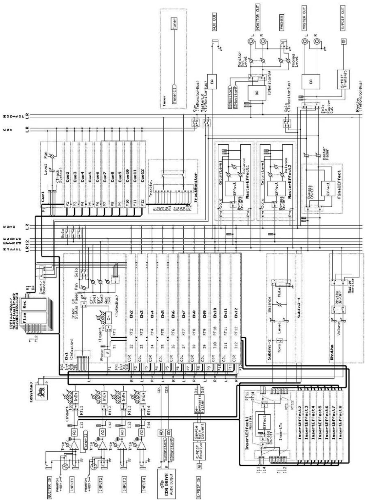
flowchart
graph TD
    subgraph Inputs
        A["INPUT1"] --> B["TunerII"]
        C["INPUT2"] --> D["TunerII"]
        E["INPUT3"] --> F["TunerII"]
        G["INPUT4"] --> H["TunerII"]
    end

    subgraph Outputs
        I["Ch1"] --> J["Chfession"]
        K["Ch2"] --> L["Ch3"]
        M["Ch4"] --> N["Ch5"]
        O["Ch6"] --> P["Ch7"]
        Q["Ch8"] --> R["Ch9"]
        S["Ch10"] --> T["Ch11"]
        U["Ch11"] --> V["Ch12"]

    end

    subgraph Control Signals
        W["Cue1"] --> X["Level"]
        X --> Y["Pan"]
        Z["P2"] --> AA["Cue2"]
        AB["P3"] --> AC["Cue3"]
        AD["P4"] --> AE["Cue4"]
        AF["P5"] --> AG["Cue5"]
        AH["P6"] --> AI["Cue6"]
        AJ["P7"] --> AK["Cue7"]
        AL["P8"] --> AM["Cue8"]
        AN["P9"] --> AO["Cue9"]
        AP["P10"] --> AQ["Cue10"]
        AR["P11"] --> AS["Cue11"]
        AT["P12"] --> AU["Cue12"]

    end

    subgraph Outputs
        V --> AV["TrackMonitor"]
        W --> AW["TrackMonitor"]
        X --> AX["Tuner"]
        Y --> AY["Tuner-1"]
        Z --> AZ["RUX OUT"]

    end

    subgraph Outputs
        AA --> BA["MasterLR (ToMonitorBus)"]
        AB --> BB["MasterLR (ToMonitorBus)"]
        AC --> BC["MasterEffect1"]
        AD --> BD["MasterEffect2"]
        AE --> BE["MasterEffect2"]
        AF --> BF["Solo (ToMonitorBus)"]
        AG --> BG["Solo Master Out"]
        AH --> BH["S/PDIF transmit"]

    end

    subgraph Outputs
        BI["S/PDIF IN"] --> BJ["S/PDIF Receiver"]
        BK["S/PDIF In"] --> BL["S/PDIF Sample Rate Convert"]
        BM["S/PDIF In"] --> BN["S/PDIF Filter DIR"]
        BO["S/PDIF In"] --> BP["S/PDIF Dir DIR"]

    subgraph Outputs
        BI --> BQ["InsertEffect1 Reset/Off"]
        BI --> BR["InsertEffect2 Reset/Off"]
        BI --> BS["InsertEffect3 Reset/Off"]
        BI --> BT["InsertEffect4 Reset/Off"]
        BI --> BU["InsertEffect5 Reset/Off"]
        BI --> BV["InsertEffect6 Reset/Off"]
        BI --> BW["InsertEffect7 Reset/Off"]
        BI --> BX["InsertEffect8 Reset/Off"]

    subgraph Outputs
        BQ --> BY["SubIni-2 Level"]
        BQ --> CA["SubIni-3-4 Level"]
        BQ --> CB["Rhythm Volume"]
        BQ --> CC["Hyster Monitor"]

    end

    subgraph Outputs
        DQ --> DA["Monitor Out Level"]
        DB["DQ MonitorSW"] --> DC["Phonics Level"]
        DD["Solo Master Out"] --> DE["RF"]
    end
Troubleshooting
Messages
About the CDRW-1
D1200 specifications
Effect Program List
Rhythm Pattern List
Index
Block diagram
MIDI implementation
[ Digital Recording Studio ]
Model D1200
MIDI Implementation Chart
Date : 2002. 4. 30
| Function Transmitted Recognized Remarks | |||||
| Basic Channel | Default Changed | ×× | ×× | ||
| Mode | MemorizedMessages Altered | ××***** | ×× | ||
| Note Number: | True Voice | ×***** | 0-127 *5 | ||
| Velocity | Note OnNote Off | ×× | ○ *5× | ||
| Aftertouch | Polyphonic (Key)Monophonic (Channel) | ×× | ×○ *5 | ||
| Pitch Bend | × | ○ *5 | |||
| Control Change | 0-119 | ○ *6 | ○ *5,*6 | Effect control (reception only)All control numbers #000-119 are receivedMixer control (transmission/reception)07 Fader10 Pan12,13 EffSend1/214 AuxSend16,19,20,25 Eq Low/Mid/MidFc/Hi68,71,72,77 InEq Low/Mid/MidFc/Hi80,81,82,83 SubIn Lev/Bal/Mono/Mute86,87 MstEff1 RetLev/RetBal88,89 MstEff2 RetLev/RetBal08,94 ChannelPair/Function95 Master fader | |
| Program Change: | Variable Range | ○0-99 *7 | ○0-99 *7 | Scene numbers 1-100 | |
| System Exclusive | ○ *8 | ○ *1 | |||
| System Common | : Quarter frame: Song Position: Song Select: Tune | ○ *2○ *3×× | ○ *9××× | Received/transmitted only for 30 frame non-drop | |
| System Real Time | : Clock: Command | ○ *3○ | ○ *4○ | ||
| Aux Messages | : Local On/Off: All Notes Off: Active Sense: Reset | ×××× | ×××× | ||
| Notes *1: Received if "MMC Mode: Receive" is selected in [SYSTEM/USB] "MMC." *6: Transmitted/received for mixer control when ControlChange is enabled in [SYSTEM/USB] "MIDI." *2: Transmitted if "MTC Mstr" is selected in [SYSTEM/USB] "Sync." *3: Transmitted if "Clock Mstr" is selected in [SYSTEM/USB] "Sync." *4: Received if "MIDIClock" is selected for "SelectRecTempoTrackType" in [RHYTHM] "TmpTrk," and tempo is being recorded. *5: Received to control effects when selected in [SYSTEM/USB] "Control." *6: Transmitted/received for mixer control when ControlChange is enabled in [SYSTEM/USB] "MIDI." *7: Transmitted/received if ProgChange is enabled in [SYSTEM/USB] "MIDI." *8: Transmitted if "MMC Mode: Transmit" is selected in [SYSTEM/USB] "MMC." *9: Received if "MIDISync Mode: MTC Slave" is selected in [SYSTEM/USB] "Sync." | |||||
Mode 1: OMNI ON, POLY Mode 2: OMNI ON, MONO : Yes
Mode 3: OMNI OFF, POLY Mode 4: OMNI OFF, MONO : No
Consult your local Korg distributor for more information on MIDI IMPLEMENTATION.
O
×
IMPORTANT NOTICE TO CONSUMERS
This product has been manufactured according to strict specifications and voltage requirements that are applicable in the country in which it is intended that this product should be used. If you have purchased this product via the internet, through mail order, and/or via a telephone sale, you must verify that this product is intended to be used in the country in which you reside.
WARNING: Use of this product in any country other than that for which it is intended could be dangerous and could invalidate the manufacturer's or distributor's warranty.
Please also retain your receipt as proof of purchase otherwise your product may be disqualified from the manufacturer's or distributor's warranty.
- Digital Recording Studio
- Owner's Manual
- Precautions
- Location
- Power supply
- Interference with other electrical devices
- Handling
- Care
- Keep this manual
- Keeping foreign matter out of your equipment
- THE FCC REGULATION WARNING (for U.S.A.)
- Handling of the internal hard disk
- COPYRIGHT WARNING
- Table of Contents
- Introduction ...... 5
- Parts and their function.... 7
- Objects in the display and their function .....12
- Basic operation ....13
- Preparations ....14
- Listening to the demo song .....16
- Quick Start Tutorial......17
- Step 1: Quick recording....17
- Step 2: Overdubbing ...... 22
- Step 3. Mixing ......25
- Step 4. Mastering ...... 28
- Operation.... 31
- Song and Locate 31
- Mixer.... 35
- Effects 42
- Modeling mode.... 45
- Rhythm 48
- The Recorder 53
- Mastering 64
- Data 68
- Drive 75
- USB 77
- MIDI....79
- Upgrading the system ....81
- Reference 83
- (COUNTER) 84
- MODELING....84
- INSERT EFFECT 85
- EQ 88
- MASTER EFFECT/AUX SEND 89
- FINAL EFFECT 91
- BOUNCE....92
- CD....93
- TUNER....95
- RHYTHM 95
- INPUT/OUTPUT/SOLO....98
- SYSTEM/USB....101
- TRACK 108
- SONG 116
- IN/LOC1, OUT/LOC2, TO/LOC3, END/LOC4.....118
- MARK 119
- SCENE 120
- AUTO PUNCH ....122
- LOOP....123
- TRIGGER 123
- SCRUB 124
- METER/TRACK VIEW....125
- UNDO ....126
- Effect Parameter List.....127
- Insert (2in2outx2)/Master/Final Effect ......127
- Insert (2in2outx2), Final ....133
- Insert (1in2outx2) 134
- Insert (1in1outx4) 138
- Insert (1in1outx8) 140
- Effect Control ....141
- Modeling effects ......141
- Appendix.... 143
- Troubleshooting 143
- Messages.... 147
- About the CDRW-1 149
- D1200 specifications.... 152
- Effect Program List.... 154
- Rhythm Pattern List (215patterns).... 156
- Index 157
- Block diagram.... 159
- MIDI implementation chart 160
- Introduction
- Main features
- 12-track digital multi-track recorder
- XLR connectors with +48 V phantom power, analog inputs, dedicated guitar input jack, and digital connectors
- Mixer section provides three-band EQ with sweepable mid-range. 100 scene memories and mixer data transmission/reception via MIDI.
- Powerful modeling effects with easy icon and knob-based operation.
- Three independent effect systems for simultaneous use
- Sophisticated editing functionality
- What is 2EMS
- Conventions in this manual
- Parts and their function
- Top panel
- [INPUT 1], [INPUT 2] jacks
- [INPUT 3], [INPUT 4] jacks
- [TRIM] knob: -60...-10...+4 dBu
- [FOOT SW] jack
- [EXPRESSION PEDAL] jack
- [AUX OUT] jack
- [TRACK STATUS] keys
- [ P AN] knobs (Ch1...6), [BALANCE] knobs (Ch7...12)
- [CHANNEL] faders (Ch1...6, Ch7/8...11/12)
- [MASTER] fader
- [REW] key
- [FF] key
- [STOP] key
- [PLAY] key
- [REC] key
- [VALUE] dial
- [CURSOR] keys
- [POWER] key
- MIDI indicator
- HDD/CD access indicator
- Display
- [MODELING] key, [MODELING] knobs
- [INSERT EFFECT] key
- [EQ] key
- [MASTER EFFECT/AUX SEND] key
- [FINAL EFFECT] key
- [BOUNCE] key
- [CD] key
- [INPUT/OUTPUT/SOLO] key
- [SYSTEM/USB] key
- [TRACK] key
- [SONG] key
- [TUNER] key
- [RHYTHM] key
- [IN/LOC1] key, [OUT/LOC2] key, [TO/LOC3] key, [END/LOC4] key
- [STORE] key
- [MARK] key
- [SCENE] key
- [AUTO PUNCH] key
- [LOOP] key
- [TRIGGER] key
- [SCRUB] key
- [METER/TRACK VIEW] key
- [UNDO] key
- [NO/CANCEL] key, [YES/OK] key
- [ENTER] key
- Front panel
- CDRW-1 drive bay
- [GUITAR IN] jack
- [PHONES] jack
- [PHONES LEVEL] knob: 0...10
- Rear panel
- [DC IN] connector
- [S/P DIF OUT] jack
- [S/P DIF IN] jack
- [USB] connector
- [MIDI OUT] connector
- [MIDI IN] connector
- [MONITOR OUT L/R] jacks
- [MONITOR OUT LEVEL] knob
- [MASTER OUT L/R] jacks
- [Phantom power] switch
- Objects in the display and their function
- Objects in the display
- a: Current parameter
- b: Edit cell
- c: Popup button
- d: Toggle button
- e: Tab page
- f: Dialog box
- g: Radio buttons
- h: Icons
- i: Scroll buttons
- Basic operation
- Selecting a mode
- Selecting a tab page
- Selecting and editing a parameter
- Selecting a parameter
- Editing a parameter value
- Preparations
- Connections
- CDRW-1 connections
- 1-1. Output (audio output) connections
- Connecting audio equipment for monitoring
- 1-2. Input (audio input) connections
- Connecting a guitar
- Connecting a mic
- Connecting a keyboard
- Connecting audio devices
- Connections for digital recording
- 1-3. Connections when using external recording devices
- 1-4. Connections when using an external effect
- 1-5. Pedal connections
- Using a pedal switch to perform manual punch recording or play/stop operations
- Using a foot pedal to control an effect
- 1-6. MIDI connections
- Controlling effects or switching scenes from an external MIDI device
- Synchronizing the D1200 with a MIDI sequencer etc.
- 1-7. USB connections
- Save or backup data on your pc
- Turning the power on/off
- 2-1. Connecting the power supply
- 2-2. Turning the power on
- 2-3. Turning the power off
- The Restart function
- Display
- 3-1. Adjusting the angle
- To adjust the angle
- 3-2. Adjusting the contrast
- To adjust the contrast
- Listening to the demo song
- Demo song list
- The Game
- Play The Blues
- Quick Start Tutorial
- Step 1: Quick recording
- Step 2: Overdubbing
- Step 3. Mixing
- Step 4. Mastering
- Getting ready
- Turning on the power
- Creating a new song
- Using the modeling mode
- Setting up a rhythm
- Recording
- Play back
- Assigning inputs to the mixer
- Applying an insert effect to the keyboard.
- Overdubbing
- Overdubbing additional parts
- Applying an insert effect to a track
- Adding EQ (equalization) to each track
- Applying master effects to several tracks
- Applying the final effect
- Creating the master track
- Writing to CD
- Operation
- Song and Locate
- Creating, naming and selecting songs
- 1-1. Creating a new song
- 1-2. Editing the name of a song
- 1-3. Selecting different songs
- To select a song from the preceding or following song location
- To select a song in a non-adjacent location
- To select a song from the song list
- Using the counter display
- 2-1. Switching the counter display
- To check the remaining recording time
- 2-2. Changing the current location
- Using the counter to move to a new location
- Using [FF] and [REW] to move to a new location
- Moving backward
- Moving forward
- Moving to the beginning of the song
- Moving to the end of the song
- Using the Locate keys
- Registering a location to one of the Locate keys
- Moving to a registered Locate time
- Using a Mark to move to a new location in the song
- Registering a mark
- Moving to a registered Mark time
- Deleting a mark
- Naming a mark
- 2-3. Using the Scrub function to find an exact location
- Scrub function
- Play From function
- Play To function
- Slow Play function
- Editing a song
- 3-1. Song editing operations
- Copying a song: "CopySong"
- To copy a song
- Moving a song: "MoveSong"
- To move a song
- Deleting a song: "DeleteSong"
- To delete a song
- Protecting a song: "ProtectSong"
- To protect a song
- Mixer
- Inputting audio to the mixer
- 1-1. Analog input
- Connecting a guitar to the [GUITAR IN] jack, assigning it to mixer channel 1, and adjusting the levels
- Using the tuner
- 1-2. Digital input
- Inputting audio from a DAT connected to the [S/P DIF IN] jack into mixer channels 1 and 2
- Adjusting the mixer
- 2-1. Adjusting the volume
- To adjust the volume level of each input channel
- To adjust the overall volume level
- 2-2. Adjusting the pan
- Channel 1-6 [PAN] knobs
- Channel 7-12 [BALANCE] knobs
- When recording in stereo
- 2-3. Using EQ to adjust the tone
- Applying EQ to an analog input/Applying EQ as you record
- High EQ, Low EQ
- Mid EQ
- Applying EQ to the track playback sound
- 2-4. Pairing
- 2-5. Monitor settings
- To select which signals will be monitored
- 2-6. Adjusting the cue level
- To adjust the Cue Level
- 2-7. Solo settings
- To select a signal for soloing
- To turn solo off
- To output the solo signal from master LR
- Registering and recalling a scene
- 3-1. Registering a scene
- 3-2. Switching scenes during playback
- Automatically switching scenes while a song plays
- 3-3. Recalling a scene
- 3-4. Changing the time at which a scene is registered
- 3-5. Re-registering a scene at another time location
- 3-6. Editing and overwriting a scene
- 3-7. Deleting a scene
- 3-8. Applying filtering to all scenes
- 3-9. Using MIDI to control scenes
- MIDI output
- MIDI input
- Effects
- Overview of the effects
- Using insert effects
- ○ 1 in 2 out x 2, 1 in 1 out x 2 (input only)
- ○ 2 in 2 out x 2
- ○ 1 in 1 out x 4
- ○ 1 in 1 out x 8 (during track playback only)
- 1-1. Applying insert effects while you record (analog or rhythm only)
- Applying an effect to a guitar connected to the [GUITAR IN] jack, and recording it to track 1
- 1-2. Applying insert effects during playback
- Using the master effects
- Using the final effect
- Editing an effect
- To edit an effect
- To save the effect program
- Controlling an effect from an external device
- Using a pedal to control an insert effect
- Using an external effect
- Sending the playback sound to an external effect, and using [INPUT 3] and [INPUT 4] jacks to return it to the master LR bus
- Modeling mode
- Applying a modeling effect to your guitar
- Applying a modeling effect to your bass
- Applying a modeling effect to a mic
- Saving your modeling effect settings
- If you want to edit the effect in greater detail and save it
- To exit Modeling mode
- To restore the factory settings
- Operation in Modeling mode
- Limitations in Modeling mode
- 5-1. Internal operation in Modeling mode
- When you enter Modeling mode
- When you exit Modeling mode
- When you change the track status
- Rhythm
- Selecting and playing a rhythm
- Tuming the rhythm on/off
- Adjusting the rhythm volume
- Setting the tempo and time signature
- Selecting a rhythm pattern
- Listening to the rhythm while you record a performance
- Recording the rhythm
- Recording a rhythm pattern on tracks 1 and 2
- Setting the tempo of a song
- Manual tempo
- Tempo map
- Editing a tempo map
- Adding a tempo map to insert a rhythm pattern
- Overwriting a tempo map
- Deleting a tempo map
- Tempo track
- Recording MIDI Clock data from an external MIDI sequencer, and using it as the tempo track
- Tap tempo
- The Recorder
- Recording
- 1-1. Basic recording
- 1-2. Switching the virtual track for recording
- Recording on a different virtual track
- 1-3. Recording while you listen to other tracks play
- Trigger recording procedure
- 1-4. Re-recording a specific area: Punch-in/out
- Manual punch-in/out
- Using a foot switch for manual punch-in/out
- Auto punch-in/out
- Loop recording
- Loop recording procedure
- Playback
- 2-1. Playback
- 2-2. Program playback
- To create a program play list
- To play back a song program list
- 2-3. Other types of playback
- Playing back a different virtual track
- Loop playback
- Track editing
- 3-1. Preparations for track editing
- 3-2. Track editing procedures
- Copy a track: "CopyTrack"
- Copying track data within the same song
- Copying track data to a track in a different song
- Insert blank space: "InsertTrack"
- Inserting blank space
- Erase a track: "EraseTrack"
- Erasing data from a track
- Delete a track: "DeleteTrack"
- Deleting data from a track
- Reverse a track: "ReverseTrack"
- Copying track data in reverse
- Optimize a track: "OptimizeTrack"
- Optimizing track data
- Erasing silent audio events
- Erasing punch-in/out noise
- Exchange tracks: "SwapTrack"
- Swapping track data
- Expand/compress a track: "Exp/CompTrack"
- Copying expanded/compressed track data
- Copy an entire track/Copying to a V-track (virtual track): "CopyWholeTrack"
- Copying an entire track
- Copying to a V-track
- Exchange two entire tracks: "SwapWholeTrack"
- Swapping an entire track
- Swapping with a V-track
- Create a fade-in/fade-out: "FadeTrack"
- Fading-in
- Fading-out
- Normalize the level: "NormalizeTrack"
- Normalizing the level
- Mastering
- Bounce-recording
- 1-1. Combining multiple tracks into two tracks
- Combining twelve tracks of audio and overwrite-recording them on two tracks
- Combining twelve tracks of audio and recording them on two currently-unused virtual tracks
- Combining ten tracks of audio and two external audio sources and recording them on the two remaining tracks
- Creating an original CD
- 2-1. Creating an audio CD
- Writing a song to an CD
- Making an audio CD from a live recording
- Recording to a master tape
- Using sub inputs
- Data
- Backing up and restoring song data
- 1-1. Backing up song data
- Backing up to CD-R/RW
- Backing up to the internal USB drive
- 1-2. Restoring song data
- Restoring
- When restoring from a CD-R/RW
- When restoring from the USB drive
- Backing up and restoring effect user data
- 2-1. Backing up user effect data
- 2-2. Restoring effect user data
- Reading and writing WAV files
- 3-1. Importing (reading) a WAV file
- Importing a WAV file into the beginning of a track
- Importing a WAV file into the middle of a track
- 3-2. Exporting (writing) a WAV file
- Exporting a WAV file
- Exporting multiple WAV files
- Drive and data compatibility between models of the Digital Recording Studio series
- Using D12 data on the D1200
- Using D1200 data on the D12
- Using D16 or D1600 data on the D1200
- Using D1200 data on the D16 or D1600
- Drive
- Checking the hard disk
- Formatting the hard disk
- Erasing a CD-RW disc
- Drive capacity
- To erase A and B that remain from the first take, and recover disk space
- Deleting the Undo data
- Sharing event data
- USB
- What is USB?
- Song data
- Effect user data
- WAV files: WAV format audio files
- Saving data to your computer
- Windows users (Windows Me/2000 or later)
- Macintosh users (Mac OS9.0.4 or later)
- MIDI
- What is MIDI?
- MIDI connections
- MIDI channel settings
- MIDI messages used by the D1200
- About the MIDI implementation chart
- Using MIDI
- Controlling the D1200 from a MIDI sequencer
- Synchronizing two D1200 units
- Using MIDI for mixer control
- Recording the D1200's mixer control messages
- Using MIDI to control the D1200's mixer
- Upgrading the system
- Downloading the system file
- Upgrading via CD-ROM/R/RW
- Upgrading via USB
- Upgrading the system
- Reference
- (COUNTER)
- Counter: Counter display
- Select TimeDisp Type
- MODELING
- Category: Select an effect category
- Select Modeling Effect Category ..... [Guitar, Bass, Mic]
- Modeling 1
- Select DRIVE.....[(\*10 types)]
- Select Tube Type..... [000...100]
- Select CABINET ....[(\*12 types)]
- Factory Data....
- Modeling 2
- Exit......
- DRIVE ....[001...100]
- LEVEL..... [000...100]
- NR(NoiseReduction)..... [01...80]
- INSERT EFFECT
- InsAss: Specify the insert location and type of the insert effects
- Assign ...... [In(Input), Trk(PlayTrack)]
- SelectEffType ..... [1in2outx2, 2in2outx2, 1in1outx4, 1in1outx8]
- InsertTo....
- ■ When "Assign" is set to "In"
- ■ When "Assign" is set to "Trk"
- Pair ....
- 4a. Select ChannelPair .... [1 2...5 6]
- 4b. Select Function .... [Eq, Send, Aux, Pan]
- InsEff1: Select and edit insert effect 1
- InputLevelMeter..... (IN1, 2/CLP, -8, -18, -42dB)
- EffectNumber..[000, 001...128, U001...128, (#)]
- EditEffect...... (EffectProgramName)
- 3a. Effect Icon ....
- 3aa. Effect On/Off.....[On, Off]
- 3ab. Next......
- 3ac. Prev ....
- 3b. Effect On/Off.....[On, Off]
- 3c. Control Device ....
- 3ca. Parameter ....
- 3cb. Max, Min ....
- 3d. Control On/Off ......(On, Off)
- Bypass......
- Rename ....
- Store....
- InsEff2: Select and edit insert effect 2
- InsEff3: Select and edit insert effect 3
- InsEff4: Select and edit insert effect 4
- InsEff5-8: Select and edit insert effects 5-8
- SelectEffect5...8 ....[Eff5, Eff6, Eff7, Eff8]
- EQ
- Eq1-4: Adjust the EQ for mixer channels 1-4
- TrackLevelMeter ..... (1, 2, 3, 4/CLP, -8, -18, -42dB)
- HighEq ....[ (Fc=10kHz)-15.0...+15.0(dB) ]
- MidFc .... [100Hz...20.0k(Hz)]
- MidEq....[-15.0...+15.0(dB)]
- LowEq ....[ (Fc=100Hz)-15.0...+15.0(dB) ]
- Pair
- Eq5-8: Adjust the EQ for mixer channels 5-8
- Eq9–12: Adjust the EQ for mixer channels 9–12
- MASTER EFFECT/AUX SEND
- MstEff1: Select and edit master effect 1
- Bypass ....
- Rename....
- Store ....
- MstEff2: Select and edit master effect 2
- EffSnd1: Adjust send levels to master effect 1
- SendLevelMeter.....(SND 1/CLP, -8, -18, -42dB)
- Send.....[Ch1...6, 7-8...11-12/000...100]
- Pair ....
- EffSnd2: Adjust send levels to master effect 2
- AuxSend: Adjust the external send levels
- SendLevelMeter..... (SND A/CLP, -8, -18, -42dB)
- Aux......[Ch1...6, 7-8...11-12/000...100]
- FINAL EFFECT
- FinalEff: Select and edit the final effect
- InputLevelMeter..... (InL, R/CLP, -8, -18, -42dB)
- EffectNumber..... [F000, F001...032, u033...064]
- 3a. EffectIcon ....
- After editing the program name, use "Store" to save it. The effect program name you edited will be discarded if you do not use "Store" to save your program.
- Store......
- In the "StoreEffect" dialog box, specify the "user area number," and use the "Exec." button or the [YES/OK] key to execute. If you decide to cancel, press the [NO/CANCEL] key.
- Effects are always overwritten.
- BOUNCE
- RecMode: Select the recording mode
- Select RecMode.....[Input, Bounce]
- Bounce: Parameters for bounce-recording
- Select BounceMode ....[10Tr+2In→2Tr, 12Tr→2Tr]
- RecordVirtualTrack...... [Current, a...h]
- CD
- Prepare: Prepare to create an audio CD
- SelectTracks ..(1-2, 3-4, 5-6, 7-8, 9-10, 11-12)
- DiscAtOnce ....[On, Off]
- TrackMonitor.....[On, Off]
- TrackMonitorLevelMeter.....
- CDR/RW: Create and play back an audio CD
- CD-R/RW Information ..... (Trk01...99, BlankDisc, NoAudioTracks, NoDrive)
- Size/DeviceType......(Free, Used/R, RW, DA)
- Time display
- Disc type
- Final(Finalize)....
- Erase......
- WriteToCD
- 5a. Write Speed.....[1x, 2x, 4x, 6x, 8x]
- CD Monitor ....[On, Off]
- CD......[Abs-Track, Abs-Total]
- CD-R/RW transport keys
- TUNER
- SetUp: Specify the tempo and rhythm
- SelRhythm ....[(Rhythm Pattern List)]
- RhythmVol ....[000...100]
- Rhythm.....[On, Off]
- Pattern Length, Pattern Position ....
- TmpMap: Tempo map editing
- TempoMap.....[001...200]
- New......
- 2f. Insert.....[On, Off]
- Edit......
- Delete......
- 4a. SelectAll.....[On, Off]
- Pattern Length, Pattern Position......
- TmpTrk: Create a tempo track
- Select RecTempoTrack Type ...... [MIDIClock, MeasTap, BeatTap]
- RecStart....
- INPUT/OUTPUT/SOLO
- Ch1-6: Select inputs for mixer channels 1-6
- Ch1...6..... [Input1....4, S/PDIF L, R, RhythmL, R, CD L, R\*]
- Digiln ....[On, Off]
- SubIn......
- 3a. Stereo/Mono ....[Stereo, Mono]
- 3b. Balance ....[L63...CNT...R63]
- 3c. Fader ....[000...100]
- 3d. Mute.....[On, Off]
- Ch7-12: Select inputs for mixer channels 7-12
- InEq1-4: Adjust the EQ for inputs 1-4
- Solo: Select the signal to be soloed
- Monitor: Parameters and settings
- MasterLR
- Solo
- Rhythm.
- Cue
- Level (Cue Level)
- 5a. Pan(Ch1D6)/Balance(Ch7D12)....[L63...CNT...R63]
- 5b. Cue ....[000...100]
- Autoln ....[On, Off]
- Phase: Specify the phase of the mixer channels
- Phase ....[N, R]
- Pair ....
- SYSTEM/USB
- Control: Foot switch and control change device (pedal/MIDI) settings
- Pol(FootSwPolarity) ....[-, +]
- Func(FootSwFunction) ......
- [PunchInOut, Play/Stop, Mark]
- Device(CtrlChgDevice)......
- [Pedal, A.Touch, PitchBend, Velocity, NoteNum, CC#000...119]
- Ass(CtrlChgAssign) ....[ExpOff, InsEff1...4]
- MIDI: MIDI settings
- GlobalCh(GlobalChannel) .....[01...16]
- ProgramChange: Trans....[On, Off]
- ProgramChange: Recv..... [On, Off]
- ControlChange: Trans ....[On, Off]
- ControlChange: Recv ...... [On, Off]
- Sync: Synchronization settings
- Select MIDISync Mode ...... [MTC Mstr, MTC Slave, ClockMstr, Off]
- MTC RecvErrorLevel.....[0...9]
- MMC: MMC settings
- Select MMC Mode ....[Transmit, Receive, Off]
- MMCDevID(MMCDeviceID)..... [000...127]
- B-U/Rst: Backup and restore
- B-U/RstType.....[Backup1 Song, BackupAll Songs, BackupUserData, Restore]
- B-U/RstType: "Backup1Song"
- Source ...... (001...100)
- Drive ....[S, C, U]
- 3a. Format Type..... (B, D16[B], Audio)
- Destination ..(C, U:CDx01...99, SONG001...100)
- Exec.(Execute) ....
- B-U/RstType: "BackupAllSongs"
- Source ....(ALL)
- Destination.....(C:CDx01...99)
- Exec.(Execute) ....
- 5a. Speed ....[1x, 2x, 4x, 6x, 8x]
- B-U/RstType: "BackupUserData"
- SourceEffNo.....(EffAll, Ins001...128, Mst001...032, Fin033...064)
- Destination..... (C:CD, U:EffctName)
- B-U/RstType: "Restore"
- 3b. BackUpFileList
- 3c. Delete
- Destination ....(001...100, \*\*\*, Effect, Ins001...128, Mst001...032, Fin033...064)
- Exec.(Execute)
- DiskUtil: Disk drive management
- USB Mode
- SelOperation...... [CheckDrive/S, EraseCD-RW, Format/S, Format/U, FormatALL, LoadSystem/C, LoadSystem/U]
- "CheckDrive/S": Check the song drive
- Exec.(Execute)......
- 1a. Area......[Unused, Full, CurSng]
- "EraseCD-RW": Erase a CD-RW disc
- Exec.(Execute) ....
- 1a. Quick SW ....[On, Off]
- "Format/S": Format the song drive
- 1a. Quick SW ......[On, Off]
- 2a. Force ....[On, Off]
- "Format/U": DOS-format the USB drive
- "Format ALL": Format the entire hard disk
- 2a. Force ...... [On, Off]
- "LoadSystem/C," "LoadSystem/U,": Update the D1200's system program
- TRACK
- Vtr1-6: Select virtual tracks 1-6
- Select VirtualTrack......[1a...1h, ..., 6a...6h]
- SelectAll ....[On, Off]
- Vtr7-12: Select virtual tracks 7-12
- Select VirtualTrack..... [7-8a...7-8h, ..., 11-12a...11-12h]
- EditTrk: Perform track editing operations
- EditType.....[CopyTrack, InsertTrack, Erase Track, DeleteTrack, SwapTrack, ReverseTrack, OptimizeTrack, Exp/CompTrack, CopyWholeTrack, SwapWholeTrack, FadeTrack, NormalizeTrack]
- EditType: "CopyTrack"
- SourceTrack ..... [1...12, 1-2...11-12, 1-4...9-12, 1-6...7-12, 1-12, Clip#\*1]
- EditType: "InsertTrack"
- EditType: "EraseTrack"
- Wave ....
- EditType: "DeleteTrack"
- DestTrack...... [1...12, 1-2...11-12, 1-4...9-12, 1-6, 7-12, 1-12]
- Wave ....
- Exec.(Execute)....
- EditType: "SwapTrack"
- SourceTrack ..... [1...12, 1-2...11-12, 1-4...9-12, 1-6, 7-12, 1-12]
- DestTrack..... [1...12, 1-2...11-12, 1-4...9-12, 1-6, 7-12, 1-12]
- EditType: "ReverseTrack"
- Times.....[1...99]
- Wave ....
- EditType: "OptimizeTrack"
- DestTrack.... [1...12, 1-2...11-12, 1-4...9-12, 1-6, 7-12, 1-12]
- Mode...... [Normal, Erase Silence, Erase Punch Noise]
- Wave....
- EditType: "Exp/CompTrack"
- SourceTrack ....[1...12, 1-2...11-12]
- DestTrack ....[1...12, 1-2...11-12]
- Wave ....
- Mode ....
- 7a. SelectExp/CompMode......[Fast, Mid, Best]
- 7b. SelectPitch ....[Fixed, Variable]
- EditType: "CopyWholeTrack"
- DestVTrack..... [a..h]
- EditType: "SwapWholeTrack"
- DestVTrack.....[a..h]
- EditType: "FadeTrack"
- EditType: "NormalizeTrack"
- Import: Import WAV files
- DriveList ....[S, C, U]
- WavFileList.
- To view the contents of a folder
- To return
- 2a. Delete....
- 2b. Prvw ....
- DestTrack......[1...12, 1-2...11-12, clip#]
- FileType M.S,
- Export: Export a WAV file
- Clip#
- DriveList.....[S, C, U]
- Rename ....
- Date ....
- SONG
- SelSong: Select a song
- SongNumber ....[001...100]
- Select DispParameter ..... [Tempo, Mark, Scene]
- Rename....
- New......
- 4a. SongType..... [16Bit/12Track, 24Bit/6Track]
- 4b. MixerSet...... [New, PrevSong]
- EditSong: Perform song edit operations
- EditType...... [CopySong, MoveSong, DeleteSong, ProtectSong]
- EditType: "CopySong"
- SourceSong ..... (001...100)
- DestSong ....[001...100]
- Exec.(Execute) ....
- EditType: "MoveSong"
- EditType: "DeleteSong"
- DestSong ..... (001...100)
- Exec.(Execute) ....
- EditType: "ProtectSong"
- Protect On/Off Mark..... [On, Off]
- PrgPlay: Program playback of songs
- Select TimeDisp Type ...... [Abs-Song, Abs-Total]
- ProgramPlay List..... [01...99]
- IN/LOC1, OUT/LOC2, TO/LOC3, END/LOC4
- Locate functions
- IN/LOC1
- OUT/LOC2
- TO/LOC3
- END/LOC4
- MARK
- Mark: Edit marks
- SCENE
- MixerChannel
- InsertEffect (only if Assign is "Trk")
- MasterEffect
- FinalEffect
- ReadDel: Switch scene playback on/off, and edit scenes
- SceneRead.....[On, Off]
- Filter......
- SceneNumber ....[001...100]
- Sort....
- EditLoc ....
- Delete......
- 7a. SelectAll.....[On, Off]
- EditFilter ......
- Recall ....
- 10.OvrWrt......
- EDIT......
- MixView: Viewing pan and fader scene data
- Pan/Balance... (Pan1...Pan6, Bal7-8...Bal11-12)
- Level..... (Lev1...Lev6, Lev7-8...Lev11-12)
- Pan/fader guide ....[ ↓↓+‡↑↑→++‡+••]
- Fader
- Pan
- : The fader knob matches the internal value.
- SceneNumber ....[001...100]
- Master Level..... [000...127]
- EDIT......
- AUTO PUNCH
- AtPunch: Settings for auto punch-in/out recording
- In ..... (000:00.000...)
- Out ..... (000:00.000...)
- RolTime ....
- 4a. PreRoll.....[00...10]
- 4b. PostRoll ....[00...10]
- 4c. Unit......[Second, Meas(Measure)]
- 5c. TrackSelect .... [Track1...12]
- 5d. Zoom In/Out/Up/Down......
- LOOP
- Loop: Settings for loop playback and recording
- Loop.....[On, Off]
- Out.....(000:00.000...)
- Wave.....
- TRIGGER
- Trigger: Settings for trigger recording
- TriggerRec..... [On, Off]
- Threshold.....[000...100]
- PreTrigTime.....[000...700ms]
- SCRUB
- METER/TRACK VIEW
- Select DisplayMode......
- [PreFaderLev, PostFaderLev, TrkView1-6, TrkView7-12, TrkView1-12]
- 1a. ScaleChangeSW...... [(5, 10, 20, 40)]
- Snd1, 2/MonL, R/MstL, R ....
- PkHold..... [0,85,
- UNDO
- Effect Parameter List
- Example
- 1: RV1: Reverb Hall
- Insert (2in2outx2)/Master/Final Effect
- Reverb RV1 - RV7
- Category: Reverb-type effects
- 2: RV2: Smooth Hall
- 3: RV3: Reverb Wet Plate
- 4: RV4: Reverb Dry Plate
- : Pre Delay [msec], : Pre Delay Thru [%]
- 5: RV5: Reverb Room
- 6: RV6: Bright Room
- : ER Level, : Reverb Level
- 7: RV7: Early Reflection
- :Type
- Delay DL1 - DL6
- Category: Delay-type effects
- 8: DL1: L/C/R Delay
- : High Damp [%], : Low Damp [%]
- : Spread
- 9: DL2: St/Cross Delay (Stereo/Cross Delay)
- 10: DL3: St.Multitap Delay (Stereo Multitap Delay)
- : Mode
- : Tap1 Level
- 11: DL4: St.Modulation Delay (Stereo Modulation Delay)
- : L LFO Phase [degree], : R LFO Phase [degree]
- 12: DL5: St.Dynamic Delay (Stereo Dynamic Delay)
- : Control Target
- : Polarity, :Threshold, :Offset, :Attack, :Release
- 13: DL6: St.Auto Panning Delay (Stereo Auto Panning Delay)
- Modulation MO1–MO7 Category: Modulation-type effects
- 14: MO1: St.Chorus (Stereo Chorus)
- : L Pre Delay [msec], : R Pre Delay [msec]
- 15: MO2: St.Flanger (Stereo Flanger)
- :LFO Shape
- : High Damp [%]
- 16: MO3: St.Phaser (Stereo Phaser)
- : Resonance, : Wet/Dry
- 18: MO5: St.Tremolo (Stereo Tremolo)
- :LFO Waveform
- :LFO Phase [degree]
- 19: MO6: St.Auto Pan (Stereo Auto Pan)
- :LFO Phase
- 20: MO7: Ensemble
- : Shimmer
- Dynamics DY1 - DY7
- Category: Dynamics-type effects
- 21: DY1: St.Compressor (Stereo Compressor)
- :Envelope Select
- : Sensitivity, : Output Level
- :Attack
- 22: DY2: St.Limiter (Stereo Limiter)
- : Ratio, : Threshold [dB], : Gain Adjust [dB]
- : Attack, : Release
- : Side PEQ Insert, : Side PEQ Cutoff [Hz], : Q, : Gain [dB]
- : Trigger Monitor
- 23: DY3: Multiband Limiter
- : Low Offset [dB], : Mid Offset [dB], : High Offset [dB]
- 24: DY4: St.Gate (Stereo Gate)
- : Polarity
- :Attack, :Release
- : Delay Time
- 25: DY5: St. Exciter/Enhancer (Stereo Exciter/Enhancer)
- : Exciter Blend
- : Emphatic Point
- : Enhancer Dly L [msec], : Enhancer Dly R [msec]
- 26: DY6: St.Decimator (Stereo Decimator)
- : Pre LPF
- : Resolution, : Output Level
- 27: DY7: St.Parametric 4band EQ (Stereo Parametric 4band EQ)
- : Band1 Type, : Band4 Type
- Special Effect SE1 - SE4
- Category: Special Effect
- 28: SE1: St.Ring Modulator (Stereo Ring Modulator)
- : Fixed Frequency [Hz]
- 29: SE2: Doppler
- : Pitch Depth
- : Pan Depth
- 30: SE3: St.Analog Record (Stereo Analog Record)
- : Flutter
- : Click Level
- 31: SE4: Talking Modulator
- : Formant Shift
- : Resonance
- Insert (2in2outx2), Final
- Large size LS1 - LS7
- Category: Large size effects
- 32: LS1: St.Graphic 7band EQ (Stereo Graphic 7band EQ)
- : Type
- 33: LS2: St.Multiband Limiter (Stereo Multiband Limiter)
- 34: LS3: Vocoder
- : Noise Level
- : Modulator High Mix
- : Vocoder/Carrier, : Wet/Dry
- 35: LS4: St.Pitch Shifter (Stereo Pitch Shifter)
- :L/R Pitch
- : Mode, Fine
- 36: LS5: Early Reflections L
- 37: LS6: Rotary Speaker
- : Horn Acceleration, : Rotor Acceleration
- : Mic Distance, : Mic Spread
- 38: LS7: Center Canceller
- Insert (1in2outx2)
- 39: GT1: Guitar Multi1
- GT1 - GT6
- 40: GT2: Guitar Multi2
- 41: GT3: Guitar Multi3
- 42: GT4: Guitar Multi4
- 43: GT5: Guitar Multi5
- AS1 - AS3
- 45: AS1: Amp Simulator1
- 46: AS2: Amp Simulator2
- 47: AS3: Amp Simulator3
- PA1
- Category: Pre-amp simulator
- EB1 - EB3
- Category: Bass multi
- MS1
- Category: Mic multi
- VO1 - VO2
- Category: Vocal multi
- Effects within multi-effect programs GT1-VO2, and their parameters
- Dist (Distortion)
- NR (Noise Reduction)
- NR2 (Noise Reduction2)
- Comp (Compressor/Limiter)
- CompT (Tube Compressor/Limiter)
- Wah
- :Mode
- Filter
- AmpSim (AmpSimulator)
- CabRes (CabinetResonator)
- Tone
- Cabinet
- DeEss (Deesser)
- Cho/Fl (Chorus/Flanger)
- :Output Mode
- Delay
- S.Dly (Stereo Delay)
- Pitch (Pitch shifter)
- : Feedback Position Select, : Feedback
- MicSim (Mic Simulator)
- : Input Mic Type
- : Output Mic Type
- : Set
- Insert (1in1outx4)
- Effects within multi-effect programs MM1–MM33, and their parameters
- Phaser
- Tmml (Tremolo)
- Mt.Dly (Multitap Delay)
- Reverb (Mono Reverb)
- Gate
- Insert (1in1outx8)
- 88: MN1: OverDrive/HighGain
- 89: MN2: Compressor2
- 90: MN3: Limiter
- 91: MN4: Gate
- 92: MN5: Exciter2
- 93: MN6: Parametric 4band EQ
- 94: MN7: Amp Simulator
- 95: MN8: Multitap Delay
- 96: MN9: Chorus/Flanger2
- 97: MN10: Phaser
- 98: MN11: Expander
- Effect Control
- Cntrl (Control)
- :Param
- : Max, : Min
- Using a pedal to control wah
- Modeling effects
- ○ Guitar type
- ○ Bass type
- ○ Mic type
- Appendix
- Troubleshooting
- Nothing appears in the display
- No sound
- Can't hear the playback
- Can't hear the input sound
- Can't hear an audio CD inserted in the CDRW-1
- Can't hear sound other than the audio CD
- No sound from [AUX OUT]
- Can't hear rhythm sound
- Can't hear scrub playback
- Channel fader or EQ does not work
- Fader does not work
- EQ does not work
- Can't record
- Can't use digital input
- The input or recorded sound is noisy or distorted
- → Input
- → Output
- Effects do not apply
- Insert effects do not apply
- Can't use the expression pedal or MIDI to control an insert effect
- Can't select insert effect "1in2out x2"
- Can't select insert effect "1in1out x8"
- Can't apply master effects
- Can't apply the final effect
- Can't apply external effect ([AUX OUT])
- Rhythm sound is not output
- Rhythm sound does not go away, or sounds in duplicate (excessive volume)
- A key does not function when pressed
- MIDI sequencer won't synchronize/MIDI control is not possible
- Can't synchronize using MTC or MIDI Clock
- The D1200 won't receive MMC
- Can't use MIDI to control effects or scenes
- The D1200 does not synchronize as a slave
- Can't control another device via MMC
- The D1200 does not transmit mixer parameters
- The D1200 does not receive mixer parameters
- CD-R/RW
- CD-R/RW drive option is not recognized
- Can't write
- Can't play back on an audio CD player
- Can't back up to CD-R/RW
- WAV
- Can't preview
- Computer does not recognize the D1200
- Error occurred when you disconnected the D1200 from the computer
- When you connected the D1200, the computer asked you to install software or a device driver
- Messages
- Confirmation messages
- Completed
- Song Full
- \*\*\*ing (\*\*\* is Copy, Write, etc.)
- Obey Copyright Rules
- Error messages
- ▲ INIT Internal Hard Disk Drive
- AE Timeout
- Blank Disc
- Can't Play CD
- Disc Full
- Disk Error
- Disk Busy
- Disk Repaired 1
- Disk Repaired 2
- Disk Repaired 3
- Drive Condition Error
- Drive Full
- Illegal Disc
- Illegal Drive/Operation
- Illegal Fat Number
- Illegal Mark Point
- Illegal To-End Time
- InTime >= OutTime
- Memory Full
- MIDI Overflow
- No CDRW Disc
- No Disc
- No Drive/No Disk
- No Event
- No internal hard disk drive
- Nothing Changed
- Number Of Tracks
- Path Length Overflow
- SameFileNameExists!
- Song Protected
- System Error
- Tempo Fast
- Tempo Slow
- ToTime >= EndTime
- Track Full
- Unsupported File Type!
- Write CD Failed!
- About the CDRW-1
- Cautions for handling
- CD-R/RW handling
- Responsibility for loss of data
- Installing the CDRW-1
- If the CDRW-1 was detected
- If the CDRW-1 was not detected
- To remove the CDRW-1
- To fasten the CDRW-1 in place
- Inserting a disc
- Removing a disc
- Emergency disc removal
- Using the CDRW-1
- Playing back an audio CD
- Recording the sound of an audio CD
- D1200 specifications
- ■ Specifications
- ■ Principal specifications
- ■ Analog/digital input and output specifications
- ■ Included items
- ■ Separately sold options
- Effect Program List
- Rhythm Pattern List (215patterns)
- Index
- Numerics
- A
- B
- C
- D
- E
- F
- G
- H
- |
- L
- M
- N
- 0
- P
- R
- S
- T
- U
- V
- W
- X
- Block diagram
- IMPORTANT NOTICE TO CONSUMERS
Brand : KORG
Model : D1200CD
Category : Blender