Eyes A200 - Security Camera BirdDog - Free user manual and instructions
Find the device manual for free Eyes A200 BirdDog in PDF.


User questions about Eyes A200 BirdDog
0 question about this device. Answer the ones you know or ask your own.
Ask a new question about this device
Download the instructions for your Security Camera in PDF format for free! Find your manual Eyes A200 - BirdDog and take your electronic device back in hand. On this page are published all the documents necessary for the use of your device. Eyes A200 by BirdDog.
USER MANUAL Eyes A200 BirdDog
natural_image
Close-up of a white surveillance camera with black lens and control buttons, set against a circular gradient background (no text or symbols visible)
natural_image
Green silhouette of a bird on black background (no text or symbols)BirdDog | A200
WEATHERPROOF FULL NDI® PTZ.
USER GUIDE 2023
NDI
Table of Contents
Welcome to BirdDog....3
Using This Manual....3
First Step 3
Firmware Upgrade 3
BirdDog A200 Overview....4
Camera Features....4
Specifications 4
What's in the Box? 6
Optional Accessories 6
Quick Start Guide....7
Basic Connections....7
Power Up....7
Basic Configuration....7
Camera External Features....11
Camera Connections....11
Installing Your Camera....12
Mounting the camera....13
Powering A200 14
Starting the Camera 14
Video Output 15
Interacting with the Camera....15
Setup Camera ID, Baud Rate and Control Protocol....16
Camera Menus....18
Using the Menus 18
Exposure Menu....18
White Balance Menu 19
Picture Menu 20
Lens Parameters Menu 20
System Setup Menu....21
Function Setting Menu 22
Web Configuration Panel 25
Password Management 25
BirdUI Layout....26
Dashboard 27
Network....27
Network Details....27
NDI Network Settings 28
System....29
Password Settings 29
System Update 30
Access Manager Configuration.... 30
System Reboot 30
AV Setup 31
Device Settings.... 31
NDI Encode Settings....31
CamControl....32
Camera Control Tab 32
FreeD Tab 33
Preset Tab....33
Exposure Tab....33
White Balance Tab 34
Picture 1 Tab 36
Picture 2 Tab....36
Color Matrix Tab....37
Advanced Tab 38
External Tab....38
Scopes 39
Camera Dimensions 40
Glossary 41
Copyright
Copyright 2023 BirdDog Australia all rights reserved. No part of this manual may be copied, reproduced, translated, or distributed in any form or by any means without prior consent in writing from our company.
Trademark Acknowledgement

BirdDog and other BirdDog trademarks and logos are the property of BirdDog Australia. Other trademarks, company names and product names contained in this manual are the property of their respective owners.
• Microsoft, Windows, ActiveX, and Internet Explorer are registered trademarks of Microsoft Corporation in the U.S. and/or other countries.
- HDMI, the HDMI logo and High-Definition Multimedia Interface are the trademarks or registered trademarks of HDMI Licensing, LLC in the United States and other countries.
- Other trademarks, company names and product names contained in this manual are the property of their respective owners.
- NDI® is a registered trademark of NewTek, Inc.
Important Information
Legal Notice
To ensure account security, please change the password after your first login. You are recommended to set a strong password (no less than eight characters).
The contents of this document are subject to change without prior notice. Updates will be added to the new version of this manual. We will readily improve or update the products or procedures described in the manual.
Best effort has been made to verify the integrity and correctness of the contents in this document, but no statement, information, or recommendation in this manual shall constitute formal guarantee of any kind, expressed or implied. We shall not be held responsible for any technical or typographical errors in this manual.
The product appearance shown in this manual is for reference only and may be different from the actual appearance of your device.
Due to uncertainties such as physical environment, discrepancy may exist between the actual values and reference values provided in this manual.
Use of this document and the subsequent results shall be entirely on the user's own responsibility.
Warnings
- If the product does not work properly, please contact your dealer. Never attempt to disassemble the camera yourself. (We will not assume any responsibility for problems caused by unauthorized repair or maintenance.)
• This installation should be made by a qualified service person and should conform to all the local codes. - When shipping, the camera should be packed in its original packaging.
• Make sure the power supply voltage is correct before using the camera.
- Do not drop the camera or subject it to physical shock.
• If the camera will not be used for an extended period of time, attach the lens cap to protect the lens.
• Do not aim the camera lens directly at the sun. This may cause irreversible damage to the camera.
Maintenance Precautions
- If there is dust on the front glass surface, remove the dust gently using an oil-free brush or a rubber dust blowing ball.
- If there is grease or a dust stain on the front glass surface, clean the glass surface gently from the center outward using anti-static gloves or an oil-free cloth. If the grease or the stain still cannot be removed, use anti-static gloves or an oil-free cloth dipped with detergent and clean the glass surface gently until it is removed.
• Do not use organic solvents, such as benzene or ethanol when cleaning the front glass surface.
Regulatory Compliance
FCC Part 15
This equipment has been tested and found to comply with the limits for digital device, pursuant to part 15 of the FCC Rules. These limits are designed to provide reasonable protection against harmful interference when the equipment is operated in a commercial environment.
This equipment generates, uses, and can radiate radio frequency energy and, if not installed and used in accordance with the instruction manual, may cause harmful interference to radio communications. Operation of this equipment in a residential area is likely to cause harmful interference in which case the user will be required to correct the interference at his own expense.
This product complies with Part 15 of the FCC Rules. Operation is subject to the following two conditions:
•This device may not cause harmful interference.
- This device must accept any interference received, including interference that may cause undesired operation.
LVD/EMC Directive
This product complies with the European Low Voltage Directive 2006/95/EC and EMC Directive 2004/108/EC.
Welcome to BirdDog
Thank you for purchasing your A200 camera. If you have any questions regarding the camera, please contact your authorized dealer or view our A200 Knowledge Base.
Our website also has a User Stories page to help inspire you to get the most out of your camera.
Using This Manual
Your camera is a powerful and sophisticated device, so please read this manual before use and retain for future reference.
If you are new to the world of NDI® or BirdDog cameras, begin with the Quick Start Guide. This will give you a good introduction to the setup of your new camera.
Tip
Use the controls in your browser or PDF reader to increase the page size when viewing the diagrams to reveal much more detail.
First Step
Firmware Upgrade
Before you use your new camera, it's a good idea to upgrade to the latest firmware. We are always adding new features and improving the performance of our products, so installing the latest firmware will provide you with the best user experience.
To upgrade the firmware, please follow the Firmware Upgrade Instructions located in your firmware download folder and perform upgrade process.
The latest firmware files are available for download here: Firmware Updates
We're Invested In Your Success
At BirdDog, we pride ourselves on being approachable and easily contactable. We'd love to hear from you.
Dan Miall
Co-Founder and CEO dan@bird-dog.tv
Eamon Drew
Co-Founder and CMO eamon@bird-dog.tv
BirdDog A200 Overview
Camera Features
•Resolution: Up to 1080p60, 1080i60
•Zoom: Optical 30X Digital: 12X
•Video Compression: H.264/MJPEG
• RS485/RS422 Communication, Auto compatible with PELCO D and VISCA Protocol
- Preset store positions and image parameters (iris, white balance, exposure, picture setting).
•3D positioning, 120dB true WDR
•Video Output: SDI+IP, True Dual-Output SDI+IP Simultaneously
• Intelligent Adaptive IR Illumination up to 100Meters, IR ON/OFF is available.
•Outdoor Environmental Rating: IP67, Corrosion Resistant Treatment
• Various Image Functionalities: WDR, BLC, Defog, Day/Night
•Supports ±120°tilt / ±360°pan range, adaptive speed up to 150°/s
•Supports 255 Presets speed adaptive up 90°/s, 8 Cruises
•Support Zoom Lens Position and Direction Indicator on OSD
• Working temperature: -40^ to 60^
•Operating Humidity: 80% suitable for use
• Rain wiper
•Supports Audio input, Audio output with NDI ^® streaming.
- Input Power: AC24V and POE (BD PoE 80W Injector needed, optional)
•Firmware upgrade via USB2.0 or IP.
Specifications
Please refer to the product webpage for complete specifications.
Welcome to the Future
What is NDI®?
Your new camera has been designed to support the cutting edge NDI® video transmission standard.
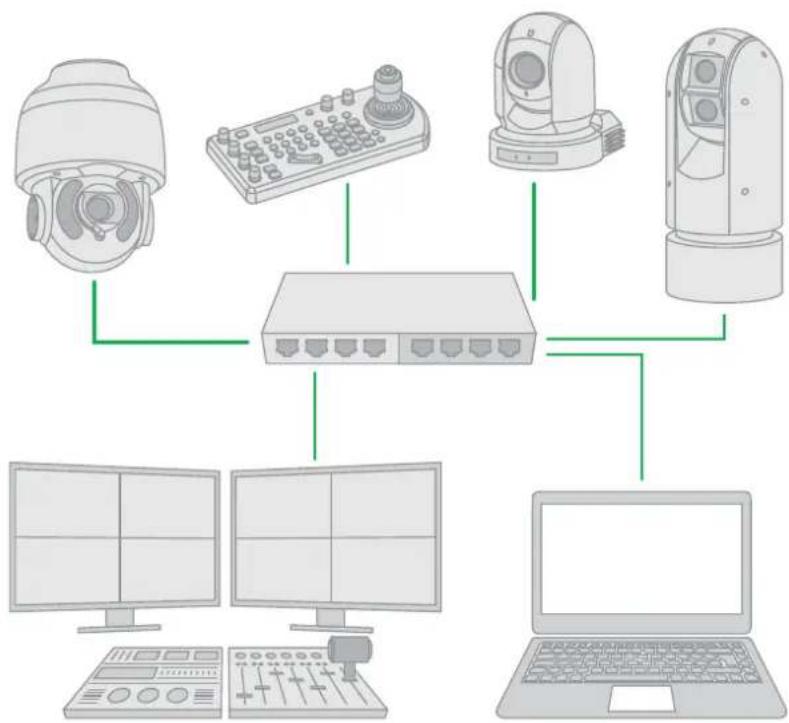
NDI® (Network Device Interface) is a high-quality, low-latency, frame-accurate standard that enables compatible devices to communicate, and deliver and receive high definition video over your existing Gigabit Ethernet network.
Operating bi-directionally, NDI devices can be auto-detected, powered and controlled over the same Ethernet cable used to send the video and audio. Even fill and key alpha channel information, as well as Tally, can be sent over this same cable. If you have a Gigabit network, you have the potential for a streamlined, interconnected, video production environment.
With the introduction of NDI 5, you can now securely share network sources between remote sites anywhere in the world – on a single network port. Even a smartphone can be a NDI source.
Transitioning to NDI® can also occur gradually. Existing SDI or HDMI signals can easily be converted to an NDI® stream and piped where required on your network and converted back only at the necessary endpoints.
BirdDog has been on the NDI® journey since the very beginning, and your camera is just one of our products designed to take advantage of the features and potential of NDI®.
For more information on NDI ^® , please refer to this page on our website.
flowchart
graph TD
    A["Camera"] --> B["Switch"]
    C["Radio"] --> B
    D["Monitor"] --> B
    E["Laptop"] --> B
    B --> F["Desktop"]
What's in the Box?
1x BirdDog EyesA200

1x Accessories
Optional Accessories
Depending on your requirements, you may need to purchase these optional accessories. Please browse to this page on our website for all your accessory needs.
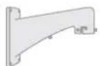
BD-A200-WM - Wall Mount
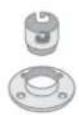
BD-A200-CM - Ceiling Mount
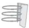
BD-A-PMA - Pole Mount
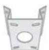
BD-A-CMA - Corner Mount
BD-A-PP97 - PoE Power Injector 97 Watt
AC Power Adaptor
Quick Start Guide
If you are new to the world of NDI® or BirdDog cameras, please follow this quick start guide to become familiar with the basic setup of your new camera. You can also view a similar online video.
Be sure to check the many helpful product videos on our YouTube page.
Basic Connections
Power
First off, you'll have to decide on how you are going to power the camera. You have two choices. You can provide 24VAC 2.5 Amp to the breakout cable or use PoE+ (Power over Ethernet) via an optional power injector. If available, PoE is the easier choice, since you can use the same Ethernet cable to power and control the camera, as well as send the video, audio and data. A BirdDog accessory 24VAC adaptor is available.
Network
Connect your camera to a network switch with a Cat5/6 cable. By default, the camera is configured to automatically obtain an IP address via DHCP. Some standalone or private networks may not have a DHCP server. After 30 seconds of waiting for an automatically assigned IP address, your camera will fall back to a default address of 192.168.100.100. To ensure that you can always reach your camera, it is recommended that you don't change this default.
Power Up
When first powered up, the camera will perform it's initialization routine by rotating to the left and then centering again.
Basic Configuration
NDI® Tools
NDI® Tools is a free suite of applications designed to introduce you to the world of IP video and is available here.
Once installed, launch the Studio Monitor (Video Monitor if on a Mac) application. This simple application allows you to view all NDI® sources on your network. Right-click on the Studio Monitor window to view your camera as an NDI® source. In the example to the right, three cameras and a desktop computer are shown as NDI® sources.
Tip
By default, the displayed sources have names that include the last five digits of your camera MAC address which is displayed on the bottom of the camera.
Clicking on your camera in the source list will display the image from your camera with the default automatic settings.
| BIRDDOG-4B077 | > |
| BIRDDOG-B95C2 | > |
| DESKTOP-E44UAFR | > |
| ZOOM-P100 | > |
| None | |
| Settings | > |
| Help | |
| http://ndi.tv | |
| Exit |
The BirdUI
text_image
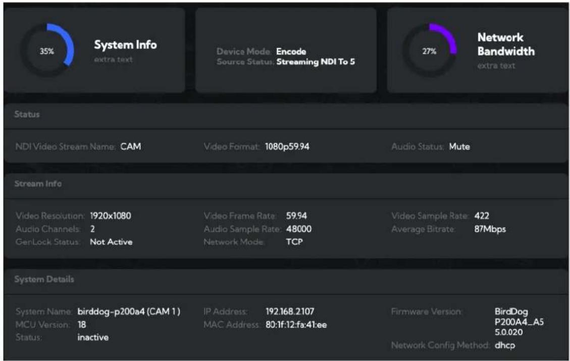
35% System Info extra text Device Mode: Encode Source Status: Streaming NDI To 5 27% Network Bandwidth extra text Status NDI Video Stream Name: CAM Video Format: 1080p59.94 Audio Status: Mute Stream Info Video Resolution: 1920x1080 Audio Channels: 2 GenLock Status: Not Active Video Frame Rate: 59.94 Audio Sample Rate: 48000 Network Mode: TCP Video Sample Rate: 422 Average Bitrate: 87Mbps System Details System Name: birddog-p200a4 (CAM 1) MCU Version: 18 Status: inactive IP Address: 192.168.2107 MAC Address: 80:1f:12:fa:41:ee Firmware Version: BirdDog P200A4_A5 5.0.020 Network Config Method: dhcpBirdDog cameras have a web interface (BirdUI) that is displayed by your computer browser and can be used to configure your camera remotely.
- Click on the gear icon on the bottom right of the Studio Monitor window.
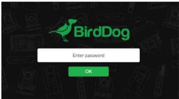
- In the displayed window, type the default password 'birddog' (all lower case) and click the OK button. The Dashboard is displayed.
The Dashboard shows important basic camera settings. For now, check that the displayed Source Status shows Streaming and take note of the frame rate that is currently output from the camera (displayed under Stream Info). This frame rate should be set identically for all cameras according to the requirements of your production. Let's see how to change the this and other important camera settings.
NDI Encode Settings
text_image
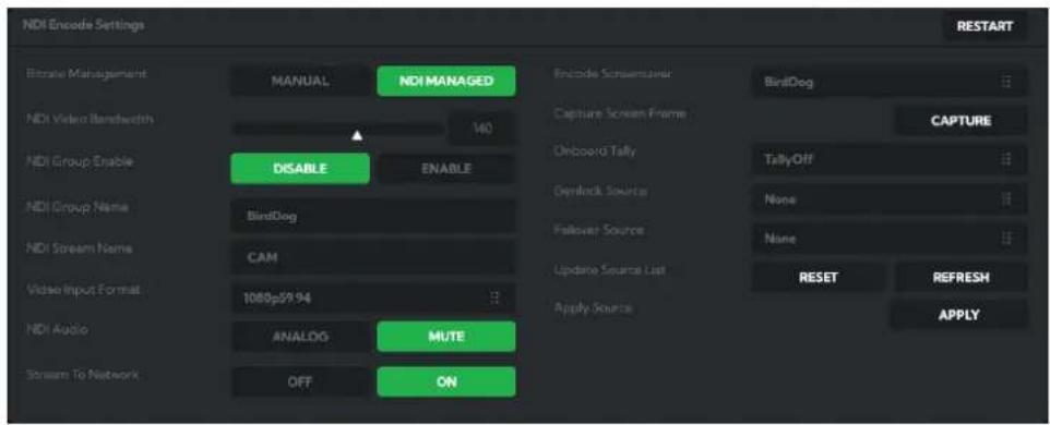
NDI Encode Settings Bitrate Management NDI Video Bandwidth NDI Group Enable NDI Group Name NDI Stream Name Video Input Format NDI Audio Stream To Network MANUAL DISABLE Birldog CAB CAM ANALOG OFF NDI MANAGED ENABLE MUTE ON Encode Screemturer Capture Screen Frame Onboard Tally Denlock Source Fallover Source Update Source List Apply Source Birldog CAPTURE TallyOff None None RESET REFRESH APPLY RESTARTBitrate Management
Because you're sending NDI® video over your computer network, you may need to be mindful of the amount of bandwidth your video will consume. By setting Bitrate Management to NDI Managed, the target bitrate will be set in accordance with the NDI® standard. This will achieve an optimum balance between bandwidth consumption and
video quality. In this mode, the video bitrate will be around 120–140 Mbps. If you do opt for Manual management, you may select a bitrate within a range of 60–360 Mbps but do this with care, as you will need to account for the capacity of the network and the receiving device.
Video Input Format
Here you can set the frame rate of the camera to match that of your production. All cameras should be set to the same frame rate.
NDI Group Enable
NDI® supports Grouping which allows you to hide the visibility of video sources to viewers that are not part of the group. If disabled, the video source is public and viewable by any receiver on your network.
NDI Stream Name
Give the output video stream of the camera a memorable name to make identification easier on NDI ^® receiving devices.
NDI Audio
You can choose to embed audio from the audio input connector into the NDI® stream or mute it.
NDI Failover Source
If the selected HDMI source is interrupted for any reason, A200 can automatically switch to a pre-determined alternative NDI® source. Select an available NDI® source for the failover function from the AvailableNDI® Sources dropdown list. Clicking the REFRESH button will add new sources to the list, whereas clicking Reset will populate the list with only active NDI® sources. Click the APPLY button to apply your failover source change.
Network Configuration
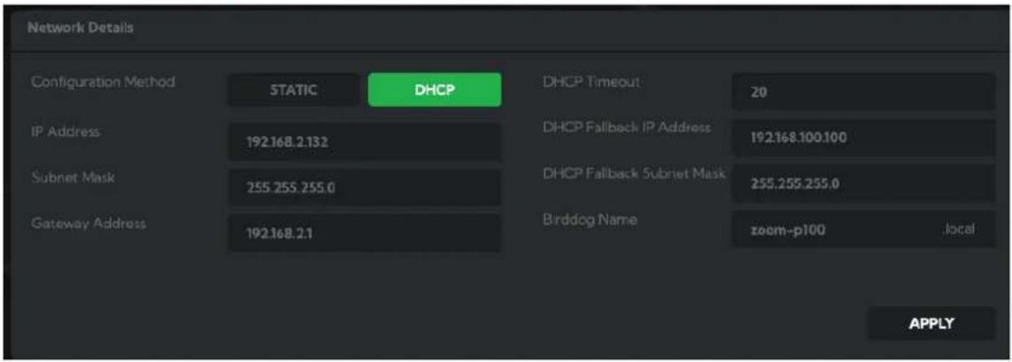
text_image
Network Details Configuration Method STATIC DHCP DHCP Timeout 20 IP Address 192.168.2.132 DHCP Fallback IP Address 192.168.100.100 Subnet Mask 255.255.255.0 DHCP Fallback Subnet Mask 255.255.255.0 Gateway Address 192.168.2.1 Birddog Name zoom-p100 locally APPLYMost computer networks provide for both automatic and manual configuration of network devices and A200 can accommodate both.
Static or DHCP
Here you can set the network configuration to either DHCP (default) or Static. DHCP simplifies the management of IP addresses on networks. No two hosts can have the same IP address, so assigning them manually can potentially lead to errors. If your network is set up for DHCP, this is generally the best configuration to choose.
If you do choose to go with a Static IP address, you'll need to add the IP Address, Subnet Mask and Gateway Address information according to the requirements of your network.
DHCP Timeout, Fallback IP address, Fallback Subnet Mask
You can set the timeout period during which A200 will look for a DHCP IP address. After this period, the camera will default to the designated fallback IP address.
This can be useful if you use your camera in other network environments. For example, if a DHCP server is available in your normal office or studio application, the camera will use the DHCP supplied IP address. If you then use the camera for another job without a DHCP server, your camera will always default to the known fallover IP address.
BirdDog Name
You can give your camera a meaningful name to make identification easier when viewing NDI® sources on a receiver such as a TriCaster, vMix or Studio Monitor. Be sure to make the name unique, as no two devices on the network should have the same name. The name can be any combination of 'a-z, 0-9, and –'.
After renaming your camera, navigate back to the SYSTEM menu and click the REBOOT button. The camera will re-initialize and you'll be good to go.
NOTE: Your computer will need to have 'Bonjour' services loaded in order to access the unit via it's user defined name. Apple devices come pre-installed with Bonjour, while Windows devices need a plugin available from here.
You're Done!
That concludes our quick start guide for A200. Your camera has many other features, so to get the most out of your camera, please review the rest of this manual.
To learn about more advanced camera options, such as exposure, white balance and color management, please refer to here in this manual.
Camera External Features
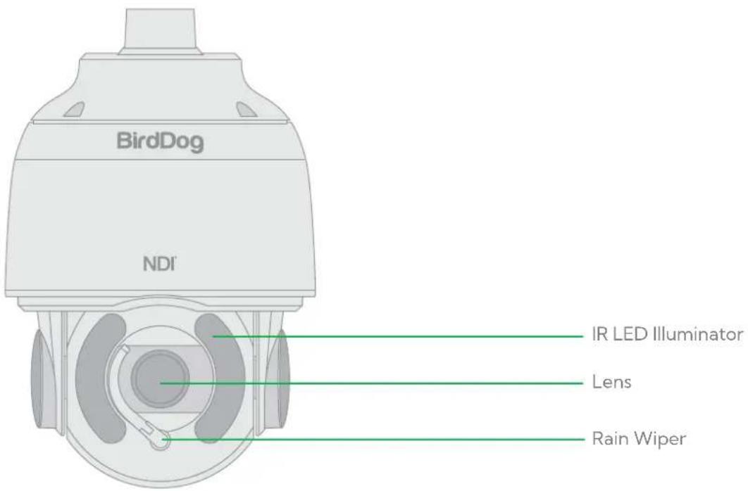
text_image
BirdDog NDI IR LED Illuminator Lens Rain WiperCamera Connections
Due to its weatherproof construction and mounting style connections to A200 are made via the breakout cable.

text_image
1 2 3 4 5 6 7 8 9 10 11 12- Audio Input • 2. Audio Output • 3. RS422 Connector (Combine with 11) • 4. Upgrade Interface • 5. Alarm Input
- BNC Connector: 3G-SDI video output • 7. RJ45 Ethernet Port • 8. AUX DC12V Output • 9. AC Power Connector
- BNC Connector: Analog video output • 11. RS485/RS422 Connector (Combine with 3) • 12. Alarm Output
NOTE: All cables are tagged separately to indicate their functions. Use a water proof / IP67 rated junction box / connection box to protect the RJ45 and other connections.
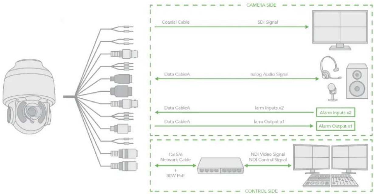
flowchart
graph TD
    A["Camera"] --> B["Coaxial Cable"]
    A --> C["Data CableA"]
    A --> D["Data CableA"]
    A --> E["Data CableA"]
    B --> F["SDI Signal"]
    C --> G["nalog Audio Signal"]
    D --> H["larm Inputs x2"]
    E --> I["larm Output x1"]
    F --> J["Monitor"]
    G --> K["Speaker"]
    H --> L["Alarm Inputs x2"]
    I --> M["Alarm Output x1"]
    N["Cat5/6 Network Cable + 80W PoE"] --> O["NDI Video Signal"]
    O --> P["Control Panel"]
    Q["CONTROL SIDE"] --> R["Monitor"]
    Q --> S["Display"]
Installing Your Camera
The following diagrams are for your reference only. See the actual product to mount your camera.
Check Camera Components and Installation Conditions.
Before mounting your camera, check the device model number and included contents against the packing list to ensure components are complete.
- Tail-Cable
- Security Lock
- Camera Body
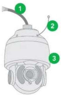
text_image
Diagram of a security camera with numbered parts labeled 1, 2, and 3Important
- Verify the bearing capacity of the mounted position.
- Verify that the mounted position meets the bearing requirements. Otherwise, you are advised to reinforce the mounted position for the device weight. For more information, see the product datasheet.
- Verify lightning protection and grounding requirements.
- Select proper lightning protection devices for the power supply, video signal interfaces, and RS485 interfaces.
•Ground the terminal properly.
Mounting the camera
NOTE!
- When mounting the camera, please install the bracket adapter to the bracket first and then mount the camera to the bracket.
•Tighten all the screws to hold the camera securely.
- For waterproofing, apply sealant between the dome and the bracket, wall veneer slits, and leading-out holes of the wall.
Wall Mount
-
Install the wall mount bracket. Get the heads of necessary cable (Wall cable) through the bracket from the wall outside of the bracket.
-
Pull the wall cable out through the secure ring.
-
Pull the wall cable out through the adaptor and install the secure ring and adaptor to the bracket.
-
Connect the camera tail-cable to the wall cable. Insert the cable into the bracket.
-
Install the two screws, insert the camera body head into the adaptor and turn to hang the camera.
-
Lock up the chain-locker from camera body to the secure ring.
-
Screw in the adaptor to lock the camera tight.
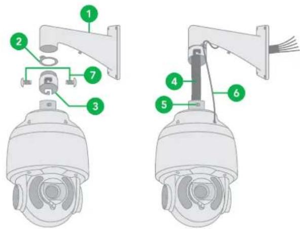
text_image
Diagram of two security camera modules with numbered components for identificationCabling Requirements
The eight wires in the network cable need to be inserted in parallel into the top of the cable connector. The cable connector needs to be crimped in position. When the cable connector is in position, ensure that the metal pieces of the cable connector are parallel to each other and the clamp of the cable connector is intact.
During installation, take care to avoid folding or twisting the cable. Note that different cable types have different physical characteristics, and acceptable digital signal transmission lengths.
-
Install the wall mount bracket. Get the heads of the wall cable through the bracket from the wall outside of the bracket.
-
Pull the wall cable out through the secure ring.
-
Pull the wall cable out through the adaptor and install the secure ring and adaptor to the bracket.
-
Connect the camera tail-cable to the wall cable. Insert the cable into the bracket.
-
Install the two screws, insert the camera body head into the adaptor and turn to hang the camera.
-
Secure the chain-locker from the camera body to the secure ring.
-
Screw in the adaptor to lock the camera tight.
Powering A200
A200 can be powered by two methods.
PoE Power Injector
For PoE power, you must use BirdDog 80W Power PoE Injector model BL-PP80. Connect this PoE injector to a network switch and then run an Ethernet cable for data transmission and power up to a distance up to 100 meters to the PTZ camera.
AC Connection
A200 can also be powered by providing 24VAC 2.5A to the power input leads of the breakout cable. To ensure proper functionality of the pan /tilt motor and LED illumination, full 24VAC 2.5A must be provided – less than 24VAC 2.5A will cause camera crashing or instability. A suitable AC power adaptor is available as a BirdDog accessory.

flowchart
graph TD
    A["Network Switch"] -->|IP Data| B["PoE Power Injector"]
    B -->|48 VDC| C["Power supply"]
    C -->|100-240 VAC| D["24 VAC"]
    B -->|PoE 80W| E["Central Node"]
Phoenix Connector
- The anode and the cathode are not distinguished for phoenix connectors of red and black cables.
- GND: yellow-green color. GND is used to ground the camera, so ensure that GND is connected to a reliable grounding point.
Starting the Camera
After you have correctly mounted the camera, connect the power. Each time the camera is powered on, it will perform a self-test to check the Pan/Tilt/Zoom (PTZ) function. After self-test, you can operate the camera.
NOTE
• The self-test process starts after the camera is powered up. Please wait until the process is finished.
- When the operating temperature is lower than zero degrees Celsius, the camera will be automatically pre-heat (the pre-heat process takes around 30 minutes). The self-test process starts only after the temperature rises above zero degrees Celsius.
Video Output
The camera can simultaneously produce SDI and NDI ^® video output.
SDI Signal
The camera can simultaneously stream SDI video output with NDI ^® video output.
- Connect SDI cable in between the camera your SDI Device/display.
NDI® Signal
The camera can simultaneously stream NDI ^® video output and SDI video output.
- Connect the camera to the network using Cat5/Cat6 network cable.
- You need to have a web browser for product configuration.
- To obtain NDI ^® video and configure NDI ^® video, please refer to NDI Encode Settings.
Interacting with the Camera
To control and configure your camera, you need to connect with control system (or control keyboard) for communication by RS-485/RS422. Set up the protocol of communication by control keyboard, the camera can auto detect VISCA and PELCO-D.
RS485 (PELCO D) control connection diagram
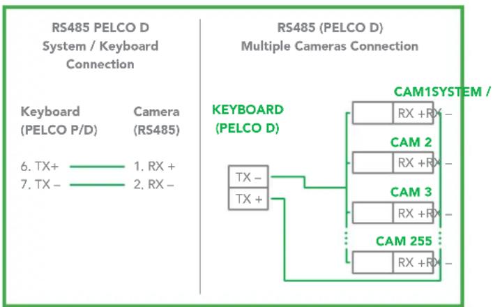
flowchart
graph TD
    A["RS485 PELCO D System / Keyboard Connection"] --> B["RS485 (PELCO D) Multiple Cameras Connection"]
    B --> C["KEYBOARD (PELCO D)"]
    C --> D["CAM1SYSTEM / RX + RX -"]
    C --> E["CAM 2 RX + RX -"]
    C --> F["CAM 3 RX + RX -"]
    C --> G["CAM 255 RX + RX -"]
    H["Keyboard (PELCO P/D)"] --> I["6. TX+"]
    H --> J["7. TX-"]
    I --> K["1. RX +"]
    J --> L["2. RX -"]
Connect the Camera's RS485+ and RS485 to RS485/TX+ and RS485/TX- on the control system/keyboard. The identity of the control system or equipment may be different; the corresponding relationship is as follows:
| RX +RS 485 | A RS 485 +RS | 485 D+ | |
| RX -RS 485 | B RS 485 -RS | 485 D- |
RS422 (VISCA) control connection diagram
SONY Keyboard RS422 Connection
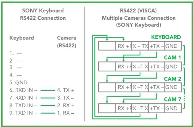
text_image
SONY Keyboard RS422 Connection RS422 (VISCA) Multiple Cameras Connection (SONY Keyboard) Keyboard Camera (RS422) 1. --- 2. --- 3. --- 4. --- 5. GND 6. RXD IN - 4. TX + 7. RXD IN + 3. TX - 8. TXD IN - 2. RX + 9. TXD IN + 1. RX - KEYBOARD RX + RX - TX + TX - GND CAM 1 RX + RX - TX + TX - GND CAM 2 RX + RX - TX + TX - GND CAM 7 RX + RX - TX + TX - GNDVISCA (Non-Sony) Keyboard RS422 Connection
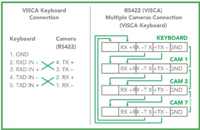
flowchart
graph TD
    A["VISCA Keyboard Connection"] --> B["Keyboard"]
    A --> C["Camera (RS422)"]
    C --> D["1. GND"]
    C --> E["2. RXD IN - 4. TX + 3. RXD IN + 3. TX - 4. TXD IN - 2. RX + 5. TXD IN + 1. RX -"]
    F["RS422 (VISCA) Multiple Cameras Connection (VISCA Keyboard)"] --> G["KEYBOARD"]
    G --> H["RX + RX - TX + TX - GND"]
    G --> I["CAM 1"]
    G --> J["CAM 2"]
    G --> K["CAM 7"]
    G --> L["RX + RX - TX + TX - GND"]
Setup Camera ID, Baud Rate and Control Protocol
In order for you to control the camera, the camera ID, baud rate and control protocol have to be set up in advance, Baud rate and the camera ID setting on the camera have to be the same as baud rate and camera ID setting on the system/control keyboard. The camera can auto detect the control method (VISCA or PELCO-D) – you only need to set up the camera address and baud rate.
Connect the camera to a monitor. There is an initial setting page displaying on the screen for 5 seconds when the camera is powered on. Shown is the factory default setting of the camera ID, baud rate and other information. It is recommended that you capture an image of these settings for use in setting the control keyboard. Set the keyboard or control system to match the camera ID, baud rate setting with the camera.
- Camera supports VISCA and PELCO-D protocols, protocol is detected automatically by the camera.
- Factory Default Setting: For both SDI and IP video, Baud Rate: 9600, Camera ID: 001, Pelco Protocol.
-
When using RS485 Pelco-D, you can control up to 255 cameras. The camera ID from 001 to 255 has to be set.
-
Use RS422 VISCA protocol can control up to 7 cameras, camera ID from 1 to 7 has to be set.
-
Supports baud rate of 2400bps, 4800bps, 9600bps and 38400bps.
-
On the keyboard side, for RS485 control, go into the camera setting menu, select the camera address/ID you want to set up for, set the baud rate to match the same as the one has been set on camera side, select Pelco D for RS485 control (please refer to the keyboard manual for instructions on how to configure the keyboard).
-
On the keyboard side, for VISCA control, select RS232/RS422 control method, set the baud rate to match the same as the one has been set on camera side.
-
On the IP control side, use a browser to login go into the camera BirdUI (default set to 192.168.100.100), go to "Setup>System>Port & Devices" setting page, set the Baud Rate, camera ID, Protocol to the same as the ones that have been set on the camera side.
-
Ensure that the SDI and IP video settings of the camera match that of the controller keyboard.
| RS485_1 | ||
| Port Mode | PTZ Control | ✓ |
| Baud Rate | 9600 | ✓ |
| Data Bits | 8 | ✓ |
| Stop Bits | 1 | ✓ |
| Parity | None | ✓ |
| Flow Control | None | ✓ |
| PTZ Protocol | PELCO-D | ✓ |
| Address Code | 1 | |
| Enable Trans-Channel | ||
NOTE
- Regarding the camera ID and Baud Rate setting, for the first communication setting, you must match the control system (or keyboard) camera ID and Baud Rate setting to the cameras.
• After communicating successfully in between the camera and the control, you can modify the ID and baud rate of the camera using the keyboard.
Camera Menus
Using the Menus
About On-Screen Menus
You can change various settings, such as shooting conditions and system setup of the camera, while observing the On Screen Display (OSD) menus on a connected computer screen. The OSD is viewable over NDI® or SDI.
The OSD menus can be displayed by clicking the CamControl/Camera Control/Menu ON/OFF button. You can then use the virtual joystick to navigate to the menu items. Push the Menu ON/OFF button to exit the menu/level.
However, the Web Configuration Panel (BirdUI) affords greater control of your camera with more parameters as well as allowing remote adjusting of camera settings over NDI, and is the recommended method of adjusting your camera.
NOTE: You cannot perform pan/tilt operations while the menu is displayed.
You can also use the BirdDog PTZ Keyboard to navigate the menus.
-
Using a Keyboard controller, run preset number 95 to display the On Screen Menu.
-
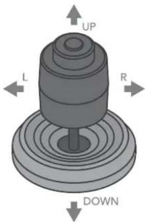
Navigate the menus by using the joystick:
a. To select the menu, push the joystick up or down.
b. To enter the menu, push the joystick to the right.
c. To confirm the desired value, push the joystick to the left.
text_image
UP L R DOWNExposure Menu
Mode
Full Auto: The exposure is adjusted automatically using the value set for EX-COMP.
Manual: Allows manual adjustment of the GAIN, shutter speed (SPEED) and iris (IRIS).
Iris Pri: Iris Priority mode. This mode allows you to set a fixed IRIS and EX-COMP with exposure achieved by automatic setting of SPEED and GAIN.
Shutter Pri: Shutter Priority mode. This mode allows you to set a fixed shutter SPEED and EX-COMP with exposure achieved by automatic setting of IRIS and GAIN.
Bright: The bright control function adjusts both gain and iris using an internal algorithm, according to a brightness level freely set by the user. Exposure is controlled by gain in dark, conditions and by iris when bright conditions. As both gain and iris are fixed, this mode is used when exposing at a fixed camera sensitivity. When switching from Full Auto or Shutter Priority Mode to Bright Mode, the current status will be retained for a short period of time.
Listed below are the various parameters you can adjust, depending on your chosen exposure mode.
Gain
Select the gain.
Speed
Select the shutter speed.
Iris
Select the iris setting.
Level
Select the brightness level.
Backlight Mode
When the background of the subject is too bright, or when the subject is too dark due to shooting in the AE mode, back light compensation will make the subject appear clearer. This is set to ON, OFF.
WIDE-D (Wide dynamic range mode)
ON, OFF. The camera distinguishes light and dark areas within the same scene, adjusts the brightness for dark areas, and also controls the blown out highlights.
Defog
ON, OFF. If the shooting scene has fog, you can open the defog function to improve the penetration of the image.
Auto Slow Shutter
ON, OFF. When AUTO SLOW SHUTTER is set to on, it can auto adjust the electronic shutter speed.
Ex-Comp (Exposure Compensation)
When MODE is set to one of FULL AUTO, SHUTTER PRI or IRIS PRI, set this item to ON to enable exposure compensation. When you set EX-COMP to ON, LEVEL appears and you can select the exposure compensation level from the following: -10.5, -9, -7.5, -6, -4.5, -3, -1.5, 0, +1.5, +3, +4.5, +6, +7.5, +9, +10.5
If you set the level to 0, exposure compensation will be disabled. Level +10.5 is the brightest and -10.5 is the darkest compensation value. When EX-COMP is set to OFF, exposure compensation does not function.
Exit
Push the joystick to the right to exit this level menu.
White Balance Menu
WB Mode (White balance mode)
Auto: This mode computes the white balance value output using color information from the entire frame with a range of values from 2500K to 7500K. This mode is the default setting.
Indoor: Sets the color temperature to 3200K.
Outdoor: Sets the color temperature to 5800K.
OPW (One Push White Balance): The One Push White Balance mode is a fixed white balance mode that may be automatically readjusted only at the request of the user (One Push Trigger), assuming that a white subject, in correct lighting conditions can occupying more than 1/2 of the image. One Push White Balance data is lost when the power is turned off. If the power is turned off, you'll need to reset One Push White Balance.
To activate OPW, click the 9 o'clock position arrow button on the virtual joystick.
ATW (Auto Tracking White Balance): Auto Tracking White balance (2000K to 10000K), allows the camera to adjust the white balance according to the temperature of the light source illuminating the subject.
User: This is a mode that enables you to manually set the control of Red and Blue gain up to 256 steps.
Outdoor Auto: This is an auto white balance mode specifically for outdoors. It allows you to capture images with natural white balance in morning and evening light.
SL Auto (Sodium Vapor Lamp Auto): This is an auto white balance mode that compensates for the orange light from sodium vapor lamps.
SL (Sodium Vapor Lamp): This is a fixed white balance mode specifically for sodium vapor lamps.
SLO Auto (Sodium Vapor Lamp Outdoor Auto): This is an auto white balance mode specifically for outdoors, which is compatible with sodium vapor lamps.
Exit
Push the joystick to the right to exit this level menu.
Picture Menu
Aperture
The aperture is used to adjust the image edge sharpness. The value of the aperture is high, the edge of the picture more clearly, the value is low, more blurred. Select the aperture from the following: 0 - 15.
Effect (Picture Effect)
Neg. Art: Applies a Negative/Positive Reversal to the image.
Black & White: Creates a Monochrome Image.
Color Gain
Adjusts the intensity of colours in the image.
Color Hue
Adjusts the color phase.
Exit
Push the joystick to the right to exit this level menu.
Lens Parameters Menu
Digital Zoom
ON, OFF. When DIGITAL ZOOM is set to on, it can use the digital zoom.
Joystick Recover
None: No effect.
A/F: After operate the camera, the mode of focus be changed to auto form manual.
A/I: After operate the camera, the mode of IRIS be changed to auto form manual.
AF-AI: After operate the camera, the mode of focus be changed to auto form manual, and, the mode of IRIS be changed to auto form manual.
A/F Recover Time
When the camera is not in operation, and in manual focus mode, after the A/F RECOVER TIME has elapsed, the camera will automatically switch to automatic focus. If the time is 0, then this function is disabled.
A/I Recover Time
When the camera is not in operation, and in manual Iris mode, after the A/I RECOVER TIME has elapsed, the camera will automatically transfer switch to automatic Iris. If the time is 0, then this function is disabled.
Focus Near Limit
The near limit from the following: 1cm, 11cm, 30cm, 0.8m, 1.2m, 1.4m, 1.65m, 2.0m, 2.5m, 3.1m, 4.2m, 6.0m, 10m, 20m.
Day/Nite Mode
Auto: The camera will automatically turn from Day mode (Color) to Night mode (Black & White) when the lighting condition is low enough, the camera illuminator will be turned on automatically at Night mode.
Day: The camera will remain in Day mode (Color) no matter how low the lighting condition is, the camera illuminator will not be turned on at Night. The image may be too dark to be seen in a low light condition.
Night: The camera will stay in Night mode (Black & White) no matter how bright the lighting condition is, the camera illuminator will be turned on all the time. The image will be stay in Black & White.
Laser
Off: Turn illumination off.
On: The illumination can be set to Day/Nite modes.
Gamma
The gamma can be set to Auto, Manual, and value from 0 to 4.
Zooming Speed
The speed of zooming can be set to value from 1 to 8.
Preset Speed
The speed of preset can be set to value from 1 to 255.
Exit
Push the joystick to the right to exit this level menu.
System Setup Menu
Factory Default
The menu is used to restore the factory settings.
Display Configuration
Zoom Lens Position: Select ON to display the zoom lens position on the screen.
Direction Indicator: Select ON to display the direction indicator on the screen.
Interface Set
Camera ID: Factory Default Setting: 001. Use RS485 Pelco-D can control up to 255 cameras, camera ID from 001 to 255 has to be set. Use RS422 VISCA protocol can control up to 7 cameras, camera ID from 1 to 7 has to be set.
Baud Rate: Select the baud rate from the following: 2400, 4800, 9600, 38400bps. Default Setting is 9600
Factory Format: Set factory default format.
NOTE
• After the camera ID and Baud rate is set, the camera has to be rebooted by powering the camera OFF and ON.
- For Dual-Output operation, the camera ID and Baud rate on the BirdUI has to be set to the same ID as the camera's for IP control.
• You may need to reboot the keyboard after you change the camera ID and Baud rate.
- Once modified and saved, the camera ID and baud rate, please modify the corresponding parameters on both the keyboard and BirdUI setting, otherwise the camera and keyboard and IP control will be unable to communicate.
Flip
Select ON to flip the image if you need to lift the camera.
SDI Video
Select the SDI video output format from the following: 1080p 60, 59.94, 50, 29.97, 25; 1080i 60, 59.94, 50; 720p 60, 59.94, 50, 29.97, 25
Pan Direction
Normal/Invert: Supports normal and inverted directions on Pan movement.
Tilt Direction
Normal/Invert: Supports normal and inverted directions on Tilt movement.
Proportional PT
Turn ON to automatically adjust the Pan and Tilt speed with various zoom ratios. For example, the higher zoom ratio you use, the slower the speed of P/T. Turn OFF to inactivate the feature to set the flat speed of Pan and Tilt.
Set North
Select ON to open this function. Turn the camera to north, and then save it by calling preset 1.
System Info
Displays Camera ID, Baud Rate and SDI Video format.
System Reset
To save the changes have been made and make the changes activated.
Exit
Push the joystick to the right to exit this level menu.
Function Setting Menu
Preset Setup
Presets are used to not only save desired Pan and Tilt positions, but also various picture settings such as brightness, exposure values, white balance and other parameters.
These other parameters are: Pan/Tilt Position, Zoom Position, Digital Zoom On/Off, Focus Auto/Manual, Focus Position, AE Mode, Shutter control parameters, Bright Control, Iris control parameters, Gain control parameters, Exposure Compensation On/Off, Exposure Level, Backlight Compensation On/Off, White Balance Mode, R/B Gain, Aperture Control, WD Parameter.
Presets Number: The current preset number that you are managing.
Preset Memory
•ON: All presets store camera positions and image parameters.
- OFF: 1-16 presets still store camera positions and image parameters, but 17-128 presets will only store camera positions. You can set the presets to number 17-128 if you don't want the preset to memorize the image parameter settings.
Set New Preset: To set up the preset of the above preset number.
- Push the joystick to the right to enter this setting menu, you will see "call preset 1 to end".
- Adjust the camera to the position that you want the camera to be, and then call the preset 1 using the keyboard to save the position to be the current preset.
- Finished.
Delete Preset: Delete the above preset.
- Push the joystick to the right to delete this preset.
- Finished.
Exit: Push the joystick to the right to exit this level menu.
In order to use the special functions of the camera, the following presets are predefined for specific functions (you can find the default predefined preset in the BirdUI: Setup > PTZ > Advanced Settings):
| OSD | OSD | SYSTEM SETUP MENU |
| 54 | SET | LENS RESET |
| 55 | CALL | OPEN BACKLIGHT |
| SET | CLOSE BACKLIGHT | |
| 56 | CALL | OPEN AUTO SHUTTER |
| SET | CLOSE AUTO SHUTTER | |
| 57 | CALL | OPEN SCREEN DISPLAY |
| SET | CLOSE SCREEN DISPLAY | |
| 58 | CALL | OPEN DIGITAL ZOOM |
| SET | CLOSE DIGITAL ZOOM | |
| 59 | CALL | DISABLE WDR |
| SET | ENABLE WDR | |
| 60 | CALL | AUTO IRIS |
| SET | MANUAL IRIS |
| 61 | CALL | AUTO WHITE BALANCE |
| SET | MANUAL WHITE BALANCE | |
| 63 | CALL | IMAGE NORMAL |
| SET | IMAGE FLIP | |
| 64 | CALL | COLOR MODE |
| SET | BLACK AND WHITE MODE | |
| 65 | CALL | AUTO DAY/NIGHT MODE |
| 95 | SET | OPEN MENU |
| 97 | CALL | START PATROL |
| SET | SET PATROL ROUTE | |
| 99 | CALL | AUTO FOCUS |
| SET | MANUAL FOCUS |
Tour Setup
The menu is used to manage the tours. Total of 4 tours can be managed.
Sequence Number: The current tour number that you are managing.
Default Dwell: Set the interval time between each of presets in the above tour, the value can be selected from 3 to 255 sec.
Edit Sequence: Set up the above tour.
- In the order of 1 - 6, add each Preset and default Dwell Time to the tour.
- The tour path will be set based on the Presets and default Dwell Time that have been set in step one.
| PRESET NUMBER | DEFAULT DWELL | PRESET NUMBER | DEFAULT DWELL | PRESET NUMBER | DEFAULT DWELL |
| 1 000 | 000 | 2 000 | 000 | 3 000 | 000 |
| 4 000 | 000 | 5 000 | 000 | 6 000 | 000 |
| 000 | 000 | 000 | 000 | 000 | 000 |
| 000 | 000 | 000 | 000 | 000 | 000 |
| ... | ... | ... | ... | ... | ... |
Run Continuously: Start the tour.
Exit: Push the joystick to the right to exit this level menu.
Pattern Setup
A pattern is a memorized, repeating series of pan, tilt, zoom, and preset functions that can be recalled with a command from a controller or automatically by a programmed function (alarm, park, event, or power-up). The menu is used to manage the patterns. Total of 4 patterns can be managed.
Pattern Number: The current pattern number that you are managing.
Record New Pattern: Set up the above pattern.
- Push the joystick to the right to enter this setting menu.
- Move the camera to the start position you want, and then call the preset 1 to save.
- Move the camera to each position you want to record the pattern, and then call the preset1 to end.
- Finished.
Run Continuously: Start the above pattern.
Exit: Push the joystick to the right to exit this level menu.
Scan Setup
The menu is used to manage the scans. Total of 4 scans can be managed.
Panning Number: The current scan number that you are managing.
Set Left Limit: Set the left limit of the camera scan.
- Push the joystick to the right to enter this setting menu.
- Move the camera to the left limit position that you want, and then call the preset 1 to save.
Set Right Limit: Set the right limit of the camera scan.
- Push the joystick to the right to enter this setting menu.
- Move the camera to the right limit position that you want, and then call the preset 1 to save.
Default Speed: Set the interval time from left to right during Scanning, and select value from 3 to 255 sec.
Run Continuously: Start the above scan.
Exit: Push the joystick to the right to exit this level menu.
Idle Timer
If the camera is idle for the designated IDLE Time, the camera will take action automatically. The menu is used to set the IDLE time, and value can be selected from 0 to 255 sec.
Idle Action
After the IDLE time, the camera starts the IDLE action automatically. Even if the idle time's value is set to 0, or during the IDLE time, manual operation will always have the priority to the response.
•The menu is used to select the IDLE action.
• The IDLE action can be selected from: OFF, PRESET1-220, SCAN1-4, TOUR1-4, PATT1-4.
Exit: Push the joystick to the right to exit this level menu.
Exit
Push the joystick to the right to exit the menu. All the setting modifications will be saved.
Web Configuration Panel
The web configuration panel (BirdUI) allows you to alter key settings of your camera, such as A/V settings, video frame rates, restarting the video processing engine, changing networking parameters, recalling PTZ presets and applying firmware updates.
Access via web browser (URL)
your camera is configured to automatically receive a network IP address from the computer network via DHCP (Dynamic Host Configuration Protocol). Most corporate, education and home networks have a DHCP server present on the network to allow this to occur.
If your camera receives an IP address automatically from this server (DHCP), the IP address can be discovered in several ways, including BirdDog Central Lite software available from here.
Your computer will need to have 'Bonjour' services loaded in order to access the unit via it's user defined name. Apple devices come pre-installed with Bonjour, while Windows devices need a plugin available from here.
Accessing your camera on a network without a DHCP server
Some standalone or private networks may not have a DHCP server. After 30 seconds of searching for an automatically assigned IP address, your camera will fall back to a default address which is: 192.168.100.100
In order to access the BirdUI on a network which is configured to a different subnet, change your computers IP address to match the BirdDog unit. Once you gain access to the BirdUI, choose your IP address to match the rest of the devices on your network.
For instructions on setting your computers IP address, please consult your computer operating system manual or IT support resources.
Password Management
Once you direct your web browser to the BirdUI you will be presented with the Dashboard. To make changes to any settings, you'll need to log in.
Default Password
The BirdUI is secured by a user-selectable password. The default password is: birddog (one word, lower case).
Password Reset
To change the password simply login using the default password, navigate to the System tab in the BirdUI, and click the APPLY button.
text_image
BirdDog Enter password OKIt is recommended to change this password in a network environment where your camera is shared with other users (e.g. not private). By entering this password, the user is granted full access to the your camera configuration settings and could interrupt a live program.
BirdUI Layout
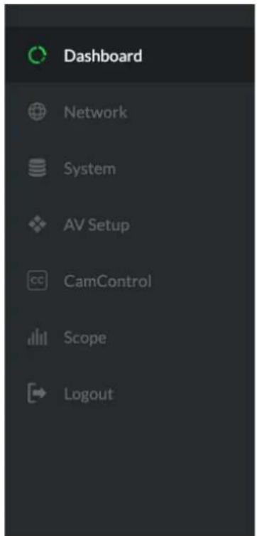
The BirdUI is organized into the following panels:
1. Dashboard
Overall view of important information such as the network connection type and video stream format and resolution.
2. Network
General network settings such as DHCP IP Address details, timeout fallback address and camera network name, as well as NDI specific network settings
3. System
System admin functions such as updates, password change, designation of group access and camera reboot.
4. AV Setup
Full NDI encode management and audio settings.
5. CamControl
Exposure, white balance, picture and color settings.
6. Scopes
Settings for the Histogram, Waveform, RGB Parade and Vectorscope.
7. Logout
Click to logout from the BirdUI.
text_image
Dashboard Network System AV Setup CamControl Scope LogoutDashboard
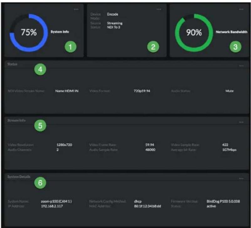
The Dashboard displays an overall view of important information.
1. System Info
Current computer system CPU utilization.
2. Device mode
Encode or Decode. For cameras, this is fixed at Decode.
3. Network Bandwidth
Network bandwidth consumption of the current NDI output stream(s).
4. Status
a. NDI Video Stream Name.
b. Selected Video Format.
c. NDI audio status.
5. Stream Info
a. Video Resolution. Number of audio channels of the camera.
b. Video Frame Rate. The audio output sample rate of the camera.
c. Video Subsample Rate (chroma subsample rate) and average NDI bitrate of the camera.
6. System Details.
a. Camera Name.
b. Network Details.
c. Online status of the camera.
d. MAC address and current firmware version of the camera.
Network
Network Details
Most computer networks provide for both automatic and manual configuration of network devices and your camera can accommodate both.
Configuration Method
Here you can set the network configuration to either DHCP (default) or Static. DHCP simplifies the management of IP addresses on networks. No two hosts can have the same IP address, so assigning them manually can potentially lead to errors. If your network is set up for DHCP, this is generally the best configuration to choose.
If you do choose to go with a Static IP address, you'll need to add the IP Address, Subnet Mask and Gateway Address information according to the requirements of your network.
pie
| Category | Value | |---|---| | System Info | 75% | | Device Mode Source Status | Encode Streaming NDI To 3 | | Network Bandwidth | 90% | | Metric | Description | | :--- | :--- | | Status | 4 | | NDI Video Server Name | Name HDMI IN | | Video Format | 720p59.94 | | Audio States | Mutie | | Stream Info | 5 | | Data Type | Value | |---|---| | Video Resolution: Audio Channels | 1280x720 2 | | Video Frame Rate: Audio Sample Rate | 59.94 48000 | | Video Sample Rate: Average bit Rate | 422 107Mbps | | System Details | Description | |---|---| | System Name: IP Address | zoom-p100 (CAM 1) 192.168.2.117 | | Network Code/Method: MAC Address | dhcp 80:1f:12:34:b8.dd | | Firmware Version Status | BindDog P100 5.0.008 active | The chart displays the percentage of system info and network bandwidth for each category. The data is presented in a grid layout with color-coded circles indicating the percentage values.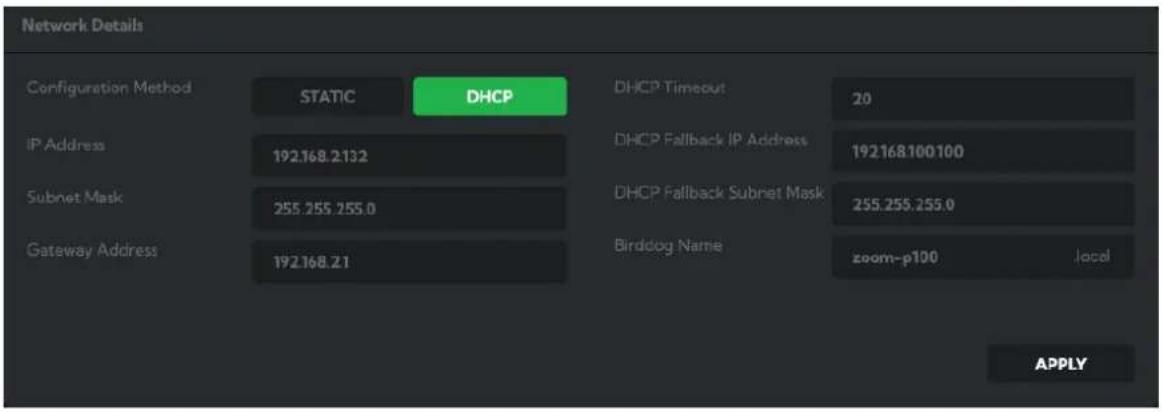
text_image
Network Details Configuration Method STATIC DHCP DHCP Timeout 20 IP Address 192.168.2132 DHCP Fallback IP Address 192168100100 Subnet Mask 255.255.255.0 DHCP Fallback Subnet Mask 255.255.255.0 Gateway Address 192.168.21 Birddog Name zoom-p100 locally APPLYDHCP Timeout, Fallback IP address, Fallback Subnet Mask
You can set the timeout period during which your camera will look for a DHCP IP address. After this period, the camera will default to the designated fallback IP address.
This can be useful if you use your camera in other network environments. For example, if a DHCP server is available in your normal office or studio application, the camera will use the DHCP supplied IP address. If you then use the camera in another application without a DHCP server, your camera will always default to the known fallover IP address. NOTE: Do not set the fallback IP address the same as the camera IP address. It is recommended to keep the fallback IP address.
BirdDog Name
You can give your camera a meaningful name to make identification easier when viewing NDI® sources on a receiver such as a TriCaster, vMix or Studio Monitor. Be sure to make the name unique, as no two devices on the network should have the same name. The name can be any combination of a-z, 0-9, and '-'.
After renaming your camera, navigate back to the Dashboard and click REBOOT DEVICE. The camera will re-initialize and you'll be good to go.
NDI Network Settings
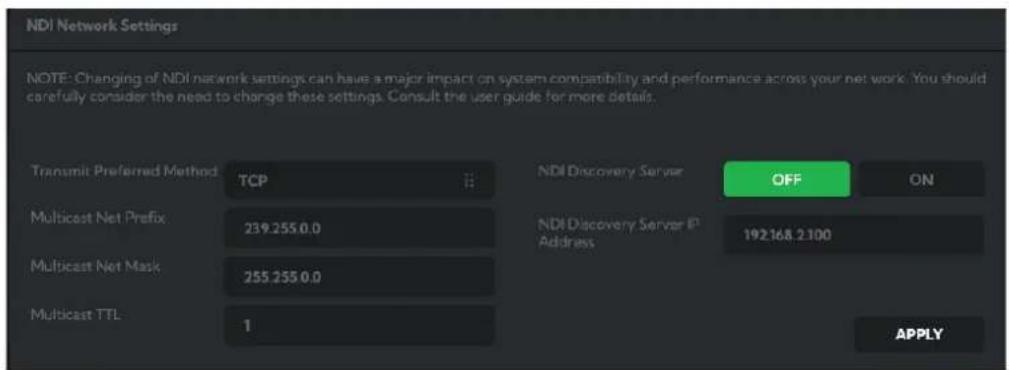
Your camera operates with the latest NDI® Libraries. There are several options to configure your camera behaviour in an NDI® network. Each configuration has its benefits, however it is recommended to utilise the default TCP transmit method unless you have reason to change.
text_image
NDI Network Settings NOTE: Changing of NDI network settings can have a major impact on system compatibility and performance across your net work. You should carefully consider the need to change these settings. Consult the user guide for more details. Transmit Preferred Method TCP NDI Discovery Server OFF ON Multicast Net Prefix 239.255.0.0 NDI Discovery Server IP Address 192168.2100 Multicast Net Mask 255.255.0.0 Multicast TTL 1 APPLYPreferred Transmit Method
TCP
TCP is the default method of transmission for NDI®. It operates well within local networks with predictable latency and limited jitter. BirdDog recommends that TCP be used for typical applications, and only using alternative transports for specific reasons.
UDP
UDP is recommended for networks where there is extended latency from one end to the other. The nature of UDP means that it does not receive a confirmation of each packet being received successfully – vastly improving performance on distance WANs. UDP can have some consequences f there are other issues on the network such as jitter or lost packets as it will not inherently re-sent a lost packet.
R-UDP (Reliable UDP)
Reduces overall network load (allowing more NDI streams) by not requiring every packet to be 'acknowledged' by every receiver – has error correction built in for smoothness and reliability.
Multicast
Multicast is especially useful for use-cases that require a single source to be received on multiple receivers simultaneously. Utilizing Multicast offloads the distribution of the NDI® A/V packets from the camera to the network infrastructure. You should take care to ensure your network is specifically configured to support Multicast as using it on an ill-prepared network can create unintended network problems.
NDI® Discovery
If you choose to use a NDI® discovery server, you can configure it in this tab. By default, NDI® utilizes mDNS (multicast Domain Name System) to create the zero configuration environment for discovery. The primary benefits of using mDNS is that it requires little or no administration to set up. Unless the network is specifically configured to not allow mDNS, NDI® sources will be discovered.
The NDI® discovery service is designed to replace the automatic discovery NDI® uses with a server that operates as an efficient centralized registry of NDI® sources that requires much less bandwidth. Multiple servers can be specified for failover redundancy. NDI® discovery server also helps with location of devices that reside on different subnets. The NDI® Discovery Server is available in the free NDI® SDK.
- If you are using one or more NDI® Discovery Servers, click the ON button.
- Enter a comma delimited list of the IP address(es) of your NDI® Discovery Server(s).
- Click the APPLY button to save your changes.
System
Password Settings

text_image
Password Settings Current Password New Password Confirm Password APPLYThe BirdUI is secured by a user-selectable password. The default password is birddog (one word, lower case). It is recommended that the default password be changed, since the BirdUI grants full access to the camera configuration settings.
You can change the password in the Password Settings tab.
- Enter the current password.
- Enter the new password. It is recommended to change this password to retain administration rights to prevent unauthorized changes. so in a network environment where PTZ Keyboard is shared with other users (e.g. not private). Confirm the new password and click Apply.
System Update
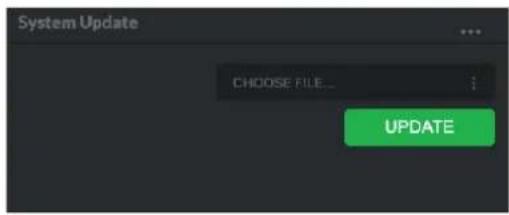
We are always adding new features and improving the performance of our products, so installing the latest firmware will provide you with the best user experience.
To upgrade the firmware, please download the firmware and follow the Firmware Upgrade Instructions located in your firmware folder.
text_image
System Update CHOOSE FILE... UPDATEAccess Manager Configuration
Remote IP List
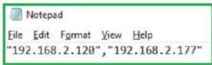
By default, NDI® devices are visible to each other only when they're on the same VLAN. If you want visibility or control of a device on a different VLAN, you need to add it's address manually as a Remote IP. You can upload, and download Remote IP Lists for sharing with other cameras.
To upload a list:
- Click the CHOOSE FILE button to load your Remote IP List in UTF-8 encoded string format.
- Click the UPDATE button. Do not upload a blank list.
text_image
Notepad File Edit Format View Help "192.168.2.120", "192.168.2.177"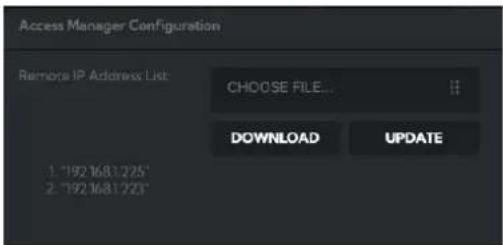
text_image
Access Manager Configuration Remote IP Address List: CHOOSE FILE... DOWNLOAD UPDATE 1. "192 1681 225" 2. "192 1681 223"NDI Group List
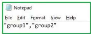
Set the NDI group list. NDI ^ groups allow you to restrict communication to only devices that belong to the same NDI ^ group. NDI ^ Groups can be very useful in larger environments to control visibility and access amongst various groups. You can upload and download group lists for sharing with other cameras. Groups also need setting up in NDI ^ Access Manager, available in NDI ^ Tools.
To upload a list:
- Click the CHOOSE FILE button to load your NDI® Group List in UTF-8 encoded string format.
- Click the UPDATE button. Do not upload a blank list.
text_image
Notepad File Edit Format View Help "group1", "group2"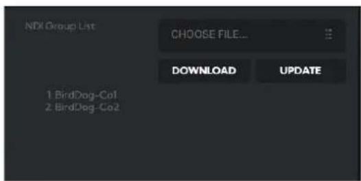
text_image
NDX Group List CHOOSE FILE... DOWNLOAD UPDATE 1 BirdDog-Co1 2 BirdDog-Co2System Reboot
Click the Reboot button to perform a camera reboot.
AV Setup
Device Settings

text_image
Device Settings Audio Output Select LOOP COMMS Audio IN Gain 50 Audio OUT Gain 50Audio Output Select
Loop: Audio from the Audio In port, for example, from a connected microphone, is directed to the Audio Out port for monitoring.
Comms: Audio from NDI stream is directed to the audio out for camera operator comms.
Audio In / Out Gain
Controls for adjusting the audio in/out gain.
NDI Encode Settings
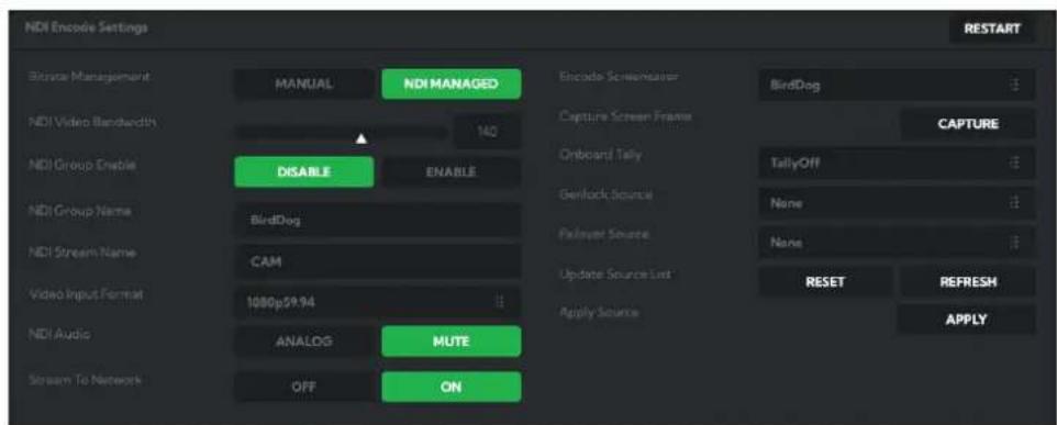
Bitrate Management
Birddog Devices allow you to set your target NDI® output bitrate. This allows you to select a compression ratio that is more efficient for your networking infrastructure (lower bandwidth) or higher image quality for critical footage. The scale allows you to select the range of 60 Mbps - 360 Mbps.
text_image
NDI Encode Settings Browse Management NDI Video Bandwidth NDI Group Enable NDI Group Name NDI Stream Name Video Input Format NDI Audio Stream To Network MANUAL DISABLE BirdDog CAM ANALOG OFF NDI MANAGED ENABLE MUTE ON Encode Screemulator Capture Screen Frame Onboard Tally Genlock Source Painover Source Update Source List Apply Source BirDog CAPTURE TallyOff None None RESET REFRESH APPLY RESTARTBy setting Bitrate Management to NDI MANAGED, the target bitrate will be set in accordance with the NDI® standard. By selecting MANUAL you are able to manually select a target bitrate. Select MANUAL with care, as you will need to account for the capacity of the network and the receiving device.
NDI Groups
NDI® supports Grouping which allows you to hide the visibility of video sources to viewers that are not part of the group. If disabled (default), the video source is public and viewable by any receiver on your network. Click on the field and type a group name. Receivers can then scan for, and select your group.
Stream Name
You can give the camera NDI output stream a meaningful name to make identification easier on any NDI-capable receiver, particularly on networks where there are a large amount of NDI streams.
NDI Video Format
Your camera is capable of outputting independent video formats for both NDI® and SDI/HDMI. This setting affects only the NDI® video output. Please note that the video rate you select here must be of the same family as the SDI/HDMI video output, for example 720p50 aligns with 1080i50/1080p50 but will not co-exist with any 29.97/30fps based camera setting.
NDI Audio
Select MUTE to disable the NDI® audio. Select ANALOG to receive audio from the rear mounted USB connector.
Stream to Network
You can choose to disable the NDI output stream.
Encoder Screensaver
Assign a captured frame, black frame, or BirdDog logo as a screensaver.
Capture Screensaver Frame
Click the Capture button to capture the current frame for use as a screensaver.
Onboard Tally
Enable the camera Tally lights.
Genlock Source
Select the genlock source from the dropdown list.
NDI Failover Source
NDI® has a failover function whewre you can designate an alternate camera or NDI® source for the receiver, should this camera become disconnected or otherwise unavailable on the network. Click on the Available NDI Sources field to select your alternate source.
Update Source List
Pressing the Refresh button will add new sources to the list, whereas pressing the RESET button will populate the list with only active NDI® sources. Click the APPLY button to apply your failover source change.
Device Restart
Restarts the NDI® stream. This may be necessary when changing key image settings, e.g., resolution.
CamControl
Camera Control Tab
Menu On / Off
To adjust cameras settings via the OSD (On Screen Display), click the Menu ON/OFF.
The OSD is visible on both the NDI® output and SDI/HDMI. Refer to here for operation.
Zoom
Click the TELE button to zoom in and the WIDE button to zoom out.
Focus Mode
Select between Auto and Manual focus modes.
Focus
Click the IN button to focus on nearer subjects and the OUT button to focus on subjects further from the camera.
Pan / Tilt / Zoom Speed
When controlling your camera over NDI® you can individually set the maximum speed of PTZ movements. Higher numbers produce faster and more sensitive movements of the camera.
Image Settings Reset
Click this button to reset all image settings to their factory default.
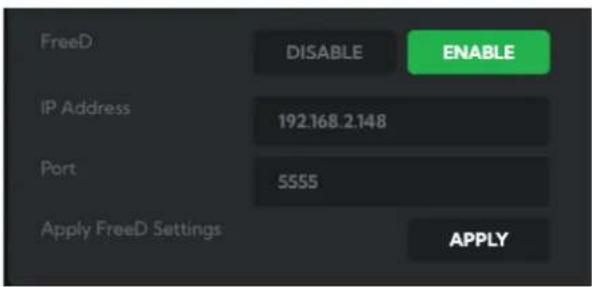
FreeD Tab
Enable or disable FreeD. FreeD is a protocol for real time camera PTZ position query. Any application that uses FreeD can use this data, usually in a virtual environment, where a physical camera move (i.e. pan, tilt, zoom or iris change) can trigger the virtual environment to follow that move in real time.
IP Address / Port
Enter the IP address of the host and the port that the data package will be sent to.
Apply FreeD Settings
Click the APPLY button to save your changes.
Preset Tab
To save a Preset select a number, make your desired changes, click the Save button and then click a Preset number. To recall a Preset, click the Preset number. You can save two separate and different types of Presets:
BirdDog
Saves only PTZ information with the Preset.
Camera
If System/Preset Memory is enabled in the camera Menu via the OSD, image parameters such as picture, white balance, exposure, focus mode, zoom positions will also be saved with the Preset.
text_image
FreeD DISABLE ENABLE IP Address 192.168.2.148 Port 5555 Apply FreeD Settings APPLY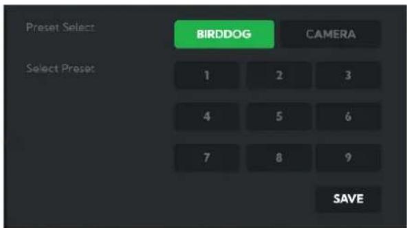
text_image
Preset Select BIRDDOG CAMERA Select Preset 1 2 3 4 5 6 7 8 9 SAVEExposure Tab
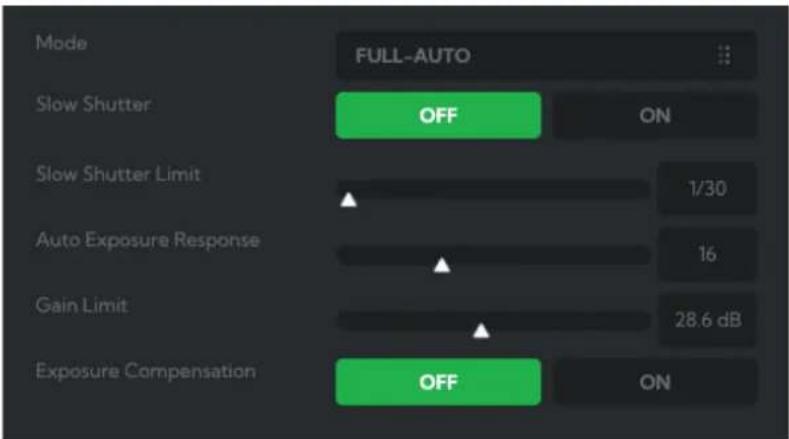
Mode
Full Auto: The exposure is adjusted automatically using the values set for EXPOSURE COMPENSATION.
Manual: Allows manual adjustment of the GAIN, IRIS and SPEED (shutter speed).
Shutter Priority: The shutter speed can be set freely by the user, and the iris and gain are set automatically, according to the brightness of the subject. The exposure is adjusted automatically using the values manually set for SPEED (shutter speed), GAIN and EXPOSURE COMPENSATION.
text_image
Mode FULL-AUTO Slow Shutter OFF ON Slow Shutter Limit 1/30 Auto Exposure Response 16 Gain Limit 28.6 dB Exposure Compensation OFF ONIris Priority: The iris can be set freely by the user. The gain and shutter speed are set automatically according to the brightness of the subject. The exposure is adjusted automatically using the values manually set for SPEED, GAIN and EXPOSURE COMPENSATION.
Depending on the mode selected, the following parameters my be displayed.
Slow Shutter
When set to "On," the slow shutter functions automatically in low light conditions. This setting is available only when the AE mode is set to "Full Auto." The default setting is Off.
Slow Shutter Limit
With certain settings in low light conditions, the shutter speed slows and the gain is increased. This function allows you to limit the shutter speed reduction. This helps prevent image shake when shooting a moving subject in low light conditions.
AE Response
The slow AE Response function allows you to reduce the exposure response speed. By default, optimum exposure can be obtained automatically within approx. 1 second.
Gain Limit
The gain limit can be set at Full Auto, Iris Priority and Shutter Priority mode. Use this setting when image signal-to-noise ratio is particularly important. Select the gain limit from the following: 9dB, 12dB, 15dB, 18dB, 21dB, 24dB, 27dB, 30dB, 33dB, 36dB.
Gain
Select the gain from the following: 0dB, 3dB, 6dB, 9dB, 12dB, 15dB, 18dB, 21dB, 24dB, 27dB, 30dB, 33dB, 36dB.
Exposure Compensation
When MODE is set to FULL AUTO, SHUTTER PRI or IRIS PRI, setting EXPOSURE COMPENSATION to ON allows exposure compensation levels to be set from -10.5 to 10.5. Setting the level to 0 disables exposure compensation. Level +10.5 is the brightest and -10.5 is the darkest compensation value. When EXPOSURE COMPENSATION is set to OFF, exposure compensation is disabled.
Iris
Select the iris from CLOSE - F1.8.
Shutter Speed
When video format is set to 720P25, 1080P50, 1080i50, 1080P25 or 720P50, shutter speed can be selected from the following: 1/1, 1/2, 1/3, 1/6, 1/12, 1/25, 1/50, 1/75, 1/100, 1/120, 1/150, 1/215, 1/300, 1/425, 1/600, 1/1000, 1/1250, 1/1750, 1/2500, 1/3500, 1/6000, 1/10K.
When video format is set to 720P30, 1080i59.94, 1080P29.97, 720P59.94, 1080P59.94, 1080I60, 1080P30, 1080P60 or 720P60, shutter speed can be selected from the following: 1/1, 1/2, 1/4, 1/8, 1/15, 1/30, 1/60, 1/90, 1/100, 1/125, 1/180, 1/250, 1/350, 1/500, 1/725, 1/1000, 1/1500, 1/2000, 1/3000, 1/4000, 1/6000, 1/10K.
High Sensitivity
In this mode, the maximum gain increases, enabling to obtain a brighter output even in a darker environment. However, if the gain reaches high level, the image will have a large amount of noise.
Bright Level
The bright control adjusts both gain and iris using an internal algorithm, according to a brightness level freely set by the user.
White Balance Tab
Cam White Balance
Auto: This mode computes the white balance value output using color information from the entire frame with a range of values from 2500K to 7500K. This mode is the default setting. Indoor: Sets the color temperature to 3200K.
Outdoor: Sets the color temperature to 5800K.
OPW (One Push White Balance): The One Push White Balance mode is a fixed white balance mode that may be automatically readjusted only at the request of the user (One Push Trigger), assuming that a white subject, in correct lighting conditions can occupying more than 1/2 of the image. One Push White Balance data is lost when the power is turned off. If the power is turned off, you'll need to reset One Push White Balance.
To activate OPW, click the One Push button.
ATW (Auto Tracking White Balance): Auto Tracking White balance (2000K to 10000K), allows the camera to adjust the white balance according to the temperature of the light source illuminating the subject.
Manual: These two user modes allow you to manually set the color balance parameters.
Outdoor Auto: This is an auto white balance mode specifically for outdoors. It allows you to capture images with natural white balance in morning and evening light. You can fine tune this setting using the MATRIX.
SVL Auto (Sodium Vapor Lamp Auto): This is an auto white balance mode that compensates for the orange light from sodium vapor lamps. You can fine tune this setting using the MATRIX.
SVL (Sodium Vapor Lamp): This is a fixed white balance mode specifically for sodium vapor lamps. You can fine tune this setting using the MATRIX.
SVL Outdoor Auto. (Sodium Vapor Lamp Outdoor Auto): This is an auto white balance mode specifically for outdoors, which is compatible with sodium vapor lamps. You can fine tune this setting using the MATRIX.
The following parameters are available depending on the chosen mode.
Speed (white balance speed)
You can adjust the speed at which the camera reaches the white convergence point when AUTO1 or AUTO2 is chosen. Values range from 1 - 5 in ascending speed.
Offset
The white convergence point can be shifted when WHITE BALANCE mode is AUTO1, AUTO2, or ONE PUSH. The range is from -7 to +7. White balance is shifted toward blue when a negative value is chosen, and it is shifted toward red when a positive value is chosen.
Matrix (Color Matrix)
You can emphasize or weaken a specific color region while keeping the white convergence point unchanged. When you turn this ON, the following items are displayed for adjustment.
Select
You can choose an internal preset matrix for matrix calculation. You can choose from STD, HIGH SAT, FL LIGHT, MOVIE, STILL, CINEMA, PRO, ITU709, and B/W. This becomes disabled when MATRIX is turned OFF.
Level (color level)
You can adjust the color density of the picture. Choose a value in the range from 0 to 14. The greater the number, the denser the colors, and vice versa. This becomes disabled when MATRIX is turned OFF.
Phase
You can adjust the color tone of the entire picture. Choose a value from -7 to +7. This becomes disabled when MATRIX is turned OFF.
R-G, R-B, G-R, G-B, B-R, B-G
You can set a coefficient for each combination of RGB individually, to adjust the hue of the entire picture. Choose a value from -99 to 0 to +99. This becomes disabled when MATRIX is turned OFF.
Cam Red/Blue Gain
Sets the intensity of red and blue colors in the image.
Cam Color Temp
Sets the color temperature of the image in degrees Kelvin.
Picture 1 Tab
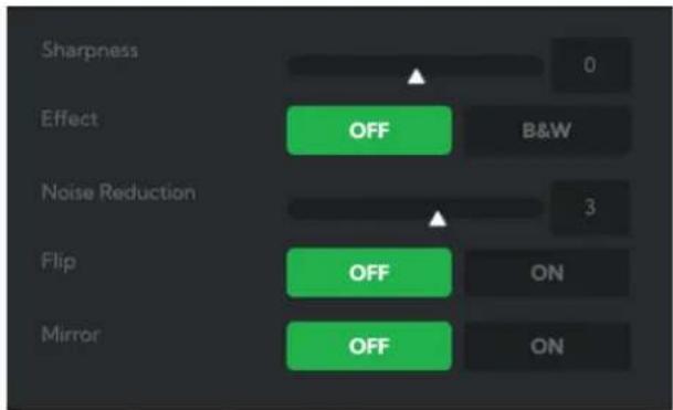
Sharpness
Adjusts the picture sharpness value from 0 to 15.
Effect
Select from Monochrome Image (B&W) or Color image (OFF).
Noise Reduction
Can reduce the level of image noise. Select from 6 levels - OFF, 1 - 5 (MAX).
Flip
Flips the image upside down for ceiling mounted cameras. Select from upright mode (OFF) or ceiling mount (ON).
Mirror
Displays a mirror image of the video image.
text_image
Sharpness Effect Noise Reduction Flip Mirror OFF B&W OFF ON OFF ONPicture 2 Tab
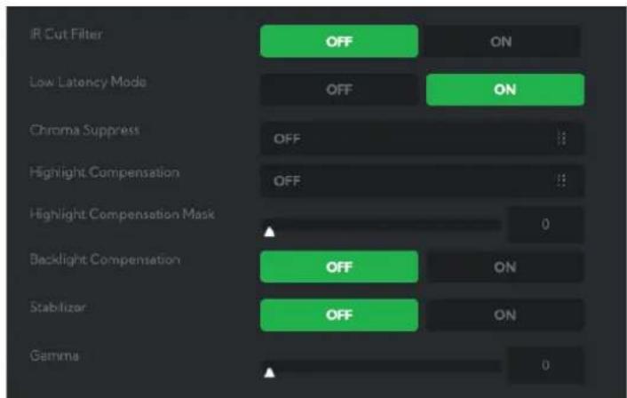
IR Cut Filter
An IR (infrared) cut filter can be disengaged for increased image sensitivity in low light conditions. The filter will automatically engage depending on the ambient light, allowing the camera to be effective in day/night environments. When the mode is set to NIGHT, a monochrome (black and white) image will be displayed.
Chroma Suppress
The chroma suppress mode can be engaged for low light conditions when color noise may be particularly noticeable. You can set the brightness from OFF, LOW, MID, HIGH in each mode of the variable gamma modes.
text_image
IR Cut Filter OFF ON Low Latency Mode OFF ON Chroma Suppress OFF 0 Highlight Compensation OFF 0 Highlight Compensation Mask 0 Backlight Compensation OFF ON Stabilizer OFF ON Gamma 0Highlight Light Compensation (HLC)
Attempts to adjust AE and AF to compensate for when high intensity spot lights are detected.
Highlight Light Compensation Mask
This setting determines how much of the spotlight is removed when making the compensation calculation.
Backlight Comp
Compensates for strong scene backlighting that can otherwise lead to the subject being too dimly exposed when shooting in auto exposure mode.
Stabilizer (Available on 30X zoom)
This function can reduce image blur caused by camera movement. The correction effect works best at vibration frequencies of around 10 Hz and may not be as effective in conditions of high frequency vibration. In such high frequency vibration conditions, turn the image stabilizer function off. The image stabilizer function uses the digital zoom methodology and may result reduced angle of view and resolution.
Gamma
Adjusts the gamma of the image from 0 to 1.
Color Matrix Tab
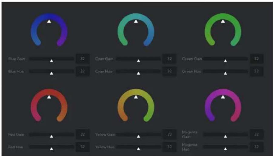
The Color Matrix features 64 levels of adjustment of Gain (Intensity) and Hue (offset) across six color sections, Red, Green, Blue, Cyan, Magenta and Yellow, and allows individual fine-tuning of each of these without affecting the response of other color components.
You can also view an online video that covers this section.
Color Gain
The Gain control of each color component defines how intense that color is represented. The default level (32) is a moderate gain which
gauge
| Channel | Value | | ------------- | ----- | | Blue Gain | 32 | | Cyan Gain | 32 | | Green Gain | 32 | | Blue Hue | 32 | | Cyan Hue | 32 | | Green Hue | 32 | | Red Gain | 32 | | Yellow Gain | 32 | | Magenta Gain | 32 | | Red Hue | 32 | | Yellow Hue | 32 |shows an even bias between all pixels that contain the color, i.e., a dark red will have the red component shown as vividly as a bright red, this generally gives a balanced look to your color representation.
By increasing the gain value, the camera will add additional intensity to all parts of the image pertaining to this color. Conversely, reducing the color gain will take some intensity out of the target color. This can be useful in some lighting conditions where certain colors appear over saturated to the camera.
Color Hue
The Color Hue option adjusts the temperature or phase in which any color is represented. When looking at the color spectrum, beyond the true color points (Red, Green, Blue, Cyan, Magenta and Yellow), there are areas where the colors transition to their neighboring color point. Color Matrix controls allow you to adjust the color offset in a negative (counter clockwise) or positive (clockwise) direction, effectively moving the cameras response to any color towards its neighboring color transition point.
Adjusting individual color Hue can assist dramatically in matching color representation from the camera to true-to-like colors or matching your camera to other cameras in your production.
Using a Colour Chart
It is recommended to utilise a colour chart or colour chip chart when adjusting the Colour Matrix controls. These charts are available readily and have colour chips for each of the colours that the camera can adjust. By utilising a colour chip chart you are more easily able to see the impact of any adjustment you are making.
Using a colour chip chart such as the Datacolor SpyderCheckr can be beneficial to fine-tuning adjustments in the camera Colour Matrix.
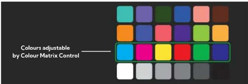
text_image
Colours adjustable by Colour Matrix ControlAdvanced Tab
Enabling video enhancement will attempt to adjust the amount of detail and gain for both the shadows and highlights of the image. This can result in a dramatically more balanced image. However, caution should be exercised as extreme settings can result in increased video noise in the shadows of the image.
Brightness
Adjusts the level of enhancement provided by the Video Enhancement function. A higher amount will result in more vivid images and more sensitivity in the shadows but can increase video noise produced by the camera.
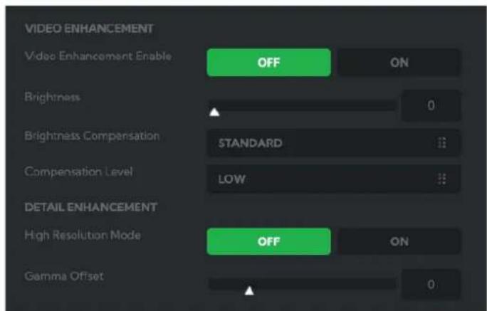
text_image
VIDEO ENHANCEMENT Video Enhancement Enable OFF ON Brightness 0 Brightness Compensation STANDARD Compensation Level LOW DETAIL ENHANCEMENT High Resolution Mode OFF ON Gamma Offset 0Brightness Compensation
This setting informs the camera where your desired level of enhancement should be focused. If your image has large amounts of dark areas that need to be enhanced then set Brightness Compensation to Dark. If your image appears over exposed, set Brightness Compensation to Light.
Compensation Level
Adjusts the mask area for the camera to apply the Video Enhancement effect. By increasing the value from low to high, the camera will attempt to adjust a greater amount of the shadow or highlight area of the image.
Gamma Offset
Controls the Shadow and Blacks of an image by changing the brightness/color levels while leaving midtones and highlight areas unaffected.
External Tab
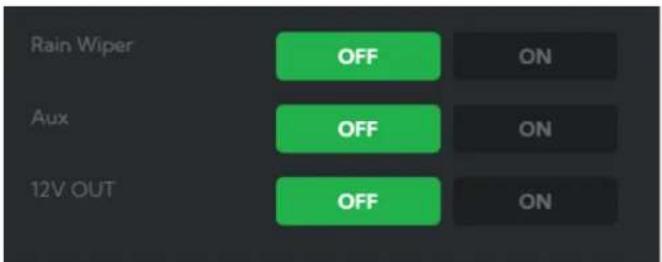
text_image
Rain Wiper OFF ON Aux OFF ON 12V OUT OFF ONRain Wiper
Activates the rain wiper.
Aux
This feature is not currently used.
12V Out
Enables the camera 12 V output.
Scopes
Since there is variation in both the eyesight of individuals and video monitors, Cam Control offers NDI video scopes to assist in evaluating the color and tonal qualities of your image.
Program / Preview Enable: Choose to overlay the scopes on either the program output, the preview output, or both.
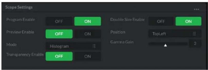
text_image
Scope Settings Program Enable OFF ON Preview Enable OFF ON Mode Histogram Transparency Enable OFF ON Double Size Enable OFF ON Position TopLeft Gamma Gain 3Transparency Enable: Click the ON button to enable scope transparency, allowing the video image to be visible behind the scopes.
Double Size Enable: Click the ON button to select the large scope size.
Position: Selects the position of the overlayed scope on the video image. Select from Top Left, Top Right, Bottom Left and Bottom Right.
Gamma Gain: Adjusts the brightness of the displayed scopes.
Mode
Histogram: The Histogram shows the distribution of luminance (brightness) in the image, from darker pixels on the left of the scope, to brighter pixels on the right. The height of the curve is a measure of the number of pixels in the image with a particular luminance value. Unlike the Waveform or RGB Parade scope, the Histogram does not indicate the left to right physical position of the luminance values in the image.
Waveform: The Waveform scope shows the distribution of luminance in the image as a waveform that ranges from zero at the lower horizontal line to 100 % intensity at the upper horizontal line. The left to right position of the values match their position in the image.
RGB Parade: The RGB Parade shows the intensity of Red, Green and Blue in the image as separate waveforms that ranges from zero at the lower horizontal line, to 100 % intensity at the upper horizontal line. For each waveform, the left to right position of the values match their position in the image.
Vector: The Vectorscope is a circular graph that displays the chrominance (hue and saturation) of the image colors. The distance from the center indicates the degree of color saturation, from zero intensity at the center of the circle, to 100% intensity at the edge of the circle.
The graph is divided into color segments, each indicated by the colored perimeter of the circle, showing the dispersion of color in the image. A Waveform scope is also displayed on the left side of the Vectorscope.
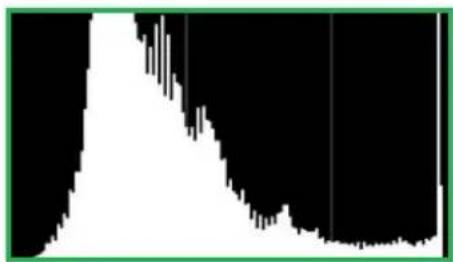
natural_image
Abstract black and white graphic with a green border (no text or symbols)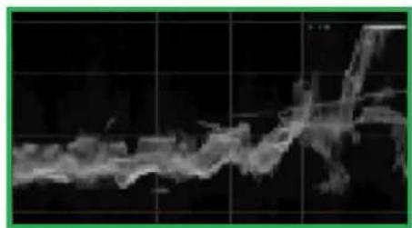
natural_image
Abstract grayscale image with fragmented shapes and grid lines, no visible text or symbols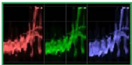
natural_image
Three-panel image showing abstract light patterns in red, green, and blue against a black grid background (no text or symbols)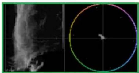
natural_image
Satellite image showing a cloud with a small object inside a circular frame against a black background (no text or symbols)Camera Dimensions
Unit: mm
Weight: 5.5 kg
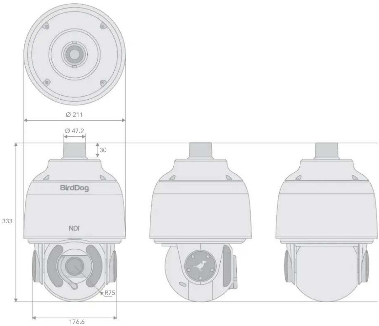
text_image
Ø 211 Ø 47.2 30 BirdDog NDI R75 333 176.6Glossary
Domain
A domain contains a group of computers that can be accessed and administered with a common set of rules. Domain can also refer to the IP address of a website on the Internet.
DNS
DNS (Domain Name System) is a system used by the Internet and private networks to translate domain names into IP addresses.
mDNS
mDNS (Multicast DNS) refers to the use of IP multicast with DNS to translate domain names into IP addresses and provide service discovery in a network that does not have access to a DNS server.
Ethernet
Ethernet, standardized as IEEE 802.3, refers to a series of technologies used to connect computers and other devices to a LAN (Local Area Network) or wide area network (WAN).
Firmware
Firmware is a class of software held in non-volatile memory that provides the low-level control for a device's hardware.
Gigabit Ethernet (GigE)
An Ethernet capable of transmitting frames at a rate of a gigabit per second. A Gigabit capable Ethernet network is recommended for NDI® production workflows.
IP
IP (Internet Protocol) is the communications protocol for the Internet, many wide area networks (WANs), and most local area networks (LANs) that defines the rules, formats, and address scheme for exchanging datagrams or packets between a source computer or device and a destination computer or device.
LAN
LAN (Local Area Network) is a network that connects computers and devices in a room, building, or group of buildings. A system of LANs can also be connected to form a WAN (Wide Area Network).
Mbps
Mbps (Megabits per second) is a unit of measurement for data transfer speed, with one megabit equal to one million bits. Network transmissions are commonly measured in Mbps.
NDI®
NDI® (Network Device Interface) is a standard allowing for transmission of video using standard LAN networking. NDI® comes in two flavours, NDI® and NDI®|HX. NDI® is a variable bit rate, I-Frame codec that reaches rates of around 140Mbps at 1080p60 and is visually lossless. NDI®|HX is a compressed, long-GOP, H.264 variant that achieves rates around 12Mbps at 1080p60.
PELCO
PELCO is a camera control protocol used with PTZ cameras. See also VISCA.
PoE
Power over Ethernet
Port
A port is a communications channel for data transmission to and from a computer on a network. Each port is identified by a 16-bit number between 0 and 65535, with each process, application, or service using a specific port (or multiple ports) for data transmission. Port can also refer to a hardware socket used to physically connect a device or device cable to your computer or network.
PTZ
Pan, tilt and zoom.
RJ45
A form of standard interface commonly used to connect computers onto Ethernet-based local area networks (LAN).
RS422, RS485, RS232
Physical layer, serial communication protocols.
Subnet
Subnet or subnetwork is a segmented piece of a larger network.
Tally
A system that indicates the on-air status of video signals usually by the use of a red illuminated lamp.
TCP
TCP (Transmission Control Protocol) is a network communications protocol.
UDP
UDP (User Datagram Protocol) is an alternative protocol to TCP that is used when reliable delivery of data packets in not required.
VISCA
VISCA is a camera control protocol used with PTZ cameras. See also PELCO.
WAN
WAN (Wide Area Network) is a network that spans a relatively broad geographical area, such as a state, region, or nation.
White Balance
White balance (WB) is the process of ensuring that white objects and by extension, all colour, in your video are rendered accurately. Without correct white balance, objects in your video display unrealistic color casts.

WELCOME TO THE FUTURE.
birddog.tv
hello@birddog.tv