
Wyse 5020 - Desktop computer DELL - Free user manual and instructions
Find the device manual for free Wyse 5020 DELL in PDF.


User questions about Wyse 5020 DELL
0 question about this device. Answer the ones you know or ask your own.
Ask a new question about this device
Download the instructions for your Desktop computer in PDF format for free! Find your manual Wyse 5020 - DELL and take your electronic device back in hand. On this page are published all the documents necessary for the use of your device. Wyse 5020 by DELL.
USER MANUAL Wyse 5020 DELL
Wyse® D Class, Wyse® X Class, and Wyse® Z Class
Flash Upgrade Option Kit
Products: D90D7, D90DW, X90m7, X90mw, Z90D7, Z90S7, Z90DW, Z90SW
Issue: 011613
PN: 883884-31L Rev. B
Copyright Notices
© 2013, Wyse Technology Inc. All rights reserved.
This manual and the software and firmware described in it are copyrighted. You may not reproduce, transmit, transcribe, store in a retrieval system, or translate into any language or computer language, in any form or by any means, electronic, mechanical, magnetic, optical, chemical, manual or otherwise, any part of this publication without express written permission.
End User License Agreement ("License")
A copy of the Wyse Technology End User License Agreement is included in the software and provided for your reference only. The License at http://www.wyse.com/license as of the purchase date is the controlling licensing agreement. By copying, using, or installing the software or the product, you agree to be bound by those terms.
Trademarks
The Wyse and PocketCloud logos and Wyse and PocketCloud are trademarks of Wyse Technology Inc. Other product names mentioned herein are for identification purposes only and may be trademarks and/or registered trademarks of their respective companies. Specifications subject to change without notice.
Restricted Rights Legend
You acknowledge that the Software is of U.S. origin. You agree to comply with all applicable international and national laws that apply to the Software, including the U.S. Export Administration Regulations, as well as end-user, end-use and country destination restrictions issued by U.S. and other governments. For additional information on exporting the Software, see http://www.microsoft.com/exporting.
Ordering Information
For availability, pricing, and ordering information in the United States and Canada, call 1-800-GET-WYSE (1-800-438-9973) or visit us at wyse.com. In all other countries, contact your sales representative.
Contents
1 Introduction 1
Kit Contents 1
Kit Warranty 1
Overview 1
Wyse Technical Support 2
Related Documentation and Services 2
Wyse Online Community 2
2 Installing D Class Flash 3
Requirements 3
Procedures 3
What's Next 5
3 Installing X Class Flash 7
Requirements 7
Procedures 7
What's Next 8
4 Installing Z Class Flash 9
Requirements 9
Procedures 9
What's Next 11
5 Installing Firmware 13
Requirements 13
Procedures 14
Troubleshooting 19
USB Keys - Troubleshooting Boot Issues 19
SanDisk Cruiser Flash Drives - Troubleshooting Partition Issues
iv Contents
This page intentionally blank.
1 Introduction
This guide provides step-by-step instructions to upgrade flash in the following products:
• D Class:
· D90D7
- D90DW
• X Class:
· X90m7
· X90mw
• Z Class:
· Z90D7
· Z90S7
- Z90DW
· Z90SW
Kit Contents
The kit includes a Flash module.
Kit Warranty
The warranty on this kit assumes the remaining months of warranty of the thin client in which it is installed, or for 90 days, whichever is greater. Installation of this kit will not void the factory warranty, however the user will be responsible for damage due to improper installation.
Overview
To upgrade flash:
- Perform a hardware installation (install new flash) by completing one of the following (depending on your thin client class):
- "Installing D Class Flash"
- "Installing X Class Flash"
- "Installing Z Class Flash"
- Complete "Installing Firmware."
Wyse Technical Support
To access Wyse technical resources, visit http://www.wyse.com/support. If you still have questions, you can submit your questions using the Wyse Self-Service Center at http://support.wyse.com/selfservice.html or call Customer Support at 1-800-800-WYSE (toll free in U.S. and Canada). Hours of operation are from 6:00 A.M. to 5:00 P.M. Pacific Time, Monday through Friday.
To access international support, visit http://www.wyse.com/global.
Related Documentation and Services
Fact Sheets containing the features of hardware products are available on the Wyse Web site. Go to http://www.wyse.com/products and use the Cloud clients tab to locate and download the Fact Sheet for your hardware product.
Administrator and other documentation for your cloud client model are available at: http://www.wyse.com/manuals.
Wyse Online Community
Wyse maintains an online community where users of our products can seek and exchange information on user forums. Visit the Wyse Online Community forums at: http://community.wyse.com/forum.
2 Installing D Class Flash
This chapter contains information for users of Wyse D class thin clients who must install new flash.
Requirements
- Small Phillips screwdriver
WARNING: Flash modules may be susceptible to damage by Electro-Static Discharge (ESD). All industry-standard cautions should be followed to avoid ESD. Before you remove or install a module, touch any metal part of the chassis and keep that contact with the chassis during the installation process.
Procedures
CAUTION: Follow all precautions listed in the Quick-Start Guide that came with your thin client for disconnecting and reconnecting the thin client.
- Perform a proper shutdown of the thin client by closing all files and ending your session, and then pressing the power button to turn off the thin client.
- Unplug the power cord and power adapter, and remove any other cables from the thin client, and detach the vertical foot.
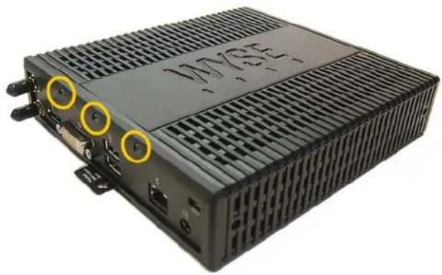
- Position the thin client horizontally, where the Wyse logo-side with four flat screws is facing downward. Using the Phillips Screwdriver, remove the three screws from the cover along the back panel edge as shown in Figure 1.
Figure 1 Removing the cover screws
natural_image
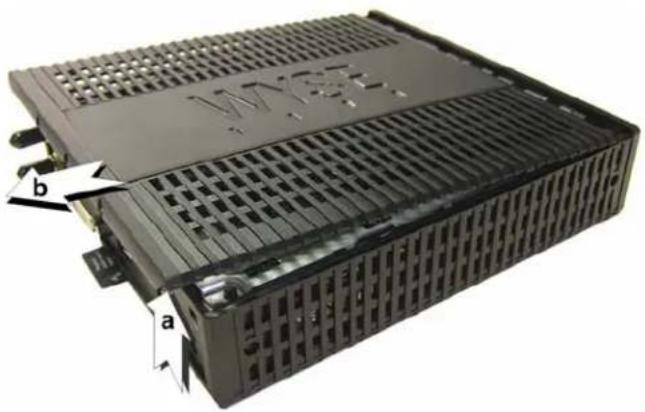
Black industrial electronic device with ventilation slots and labeled ports (no readable text or symbols beyond branding)- Place your thumbs on the top surface of the opposite end where the three screws were removed. With a continuous motion, push firmly downward and towards the back panel (pushing down unlatches the hooks under the cover). The cover will shift approximate 1/4 inch to hang over the back panel. (a) Grasp the overhanging cover edge and raise the edge about 1-1/2 inches, and then (b) pull the cover out towards the back panel at the same angle to free the opposite end of the cover from the remaining hooks, as shown in Figure 2.
Figure 2 Removing the cover
natural_image
3D rendering of a black industrial heat exchanger or cooling unit with labeled components (a, b), showing internal structure and ventilation slots (no readable text beyond labels)- Remove the cover to expose the main-board shield.
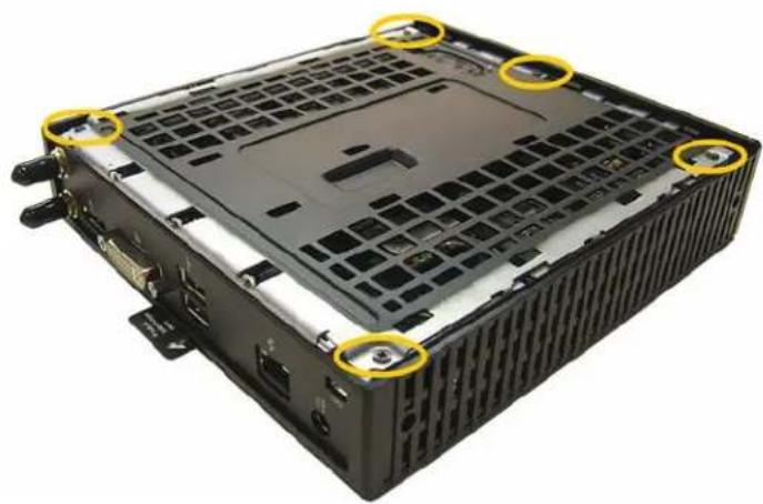
Figure 3 Main-board shield
natural_image
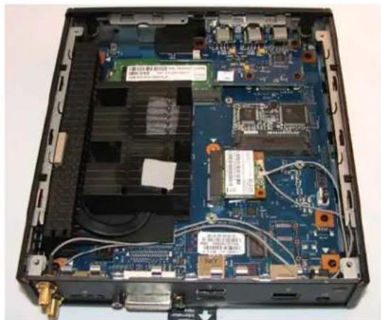
Black computer chassis with visible internal grid and mounting holes, marked with yellow circles (no text or symbols)- Using the Phillips Screwdriver, remove the five screws from the main-board shield (four corner screws and one screw mid-way along the front edge). Remove the main-board shield and unplug the speaker wire (red wire) to expose the main board and Flash module as shown in Figure 4.
Figure 4 Main board and Flash module
natural_image
Interior view of a computer case showing internal components like CPU, memory, and drive bays (no visible text or labels)- Remove the existing flash module. Locate the flash module and use the Phillips Screwdriver to remove its retaining screw as shown in Figure 5. Lift the flash module out of the socket.
Figure 5 Removing the existing flash module
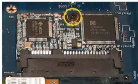
natural_image
Close-up of a printed circuit board with electronic components and a highlighted circular component (no readable text or symbols)- Install the new flash module in the reverse order of removing the original flash module. Carefully screw down its retaining screw until it is secure.
WARNING: Flash modules may be susceptible to damage by Electro-Static Discharge (ESD). All industry-standard cautions should be followed to avoid ESD. Before you remove or install a module, touch any metal part of the chassis and keep that contact with the chassis during the installation process.
-
Replace the speaker wire (plug in red wire) and the main-board shield (five screws).
-
Replace the cover in the reverse order as described in step 4 (align the cover screw tabs with the screw holes and slide the cover toward the front of the thin client).
11., Attach the cover screws in the reverse order as described in step 3.
- Connect the power cord and power adapter, attach any other cables to the thin client, and then attach the vertical foot.
CAUTION: Do not turn on the thin client. The thin client is ready to re-image, however the flash module does not contain an operating system. Turning on power to your thin client without firmware will display the error message "NO OPERATING SYSTEM FOUND."
What's Next
Continue with "Installing Firmware."
This page intentionally blank.
3 Installing X Class Flash
This chapter contains information for users of Wyse X class mobile thin clients who must install new flash.
Requirements
• Small Phillips screwdriver
WARNING: Flash modules may be susceptible to damage by Electro-Static Discharge (ESD). All industry-standard cautions should be followed to avoid ESD. Before you remove or install a module, touch any metal part of the chassis and keep that contact with the chassis during the installation process.
Procedures
CAUTION: Follow all precautions listed in the Quick-Start Guide that came with your mobile thin client for disconnecting and reconnecting the mobile thin client.
- Perform a proper shutdown of the mobile thin client by closing all files and ending your session, and then pressing the power button to turn off the mobile thin client.
- Unplug the power cord and power adapter, and then remove any other cables from the mobile thin client.
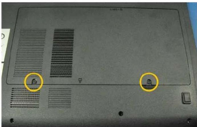
- Position the mobile thin client to access the bottom cover, and then remove the screws from the cover using a small Phillips screwdriver as shown in Figure 6.
Figure 6 Removing the bottom cover screws
natural_image
Laptop back panel with ventilation grilles and two highlighted circular annotations (no readable text or symbols)-
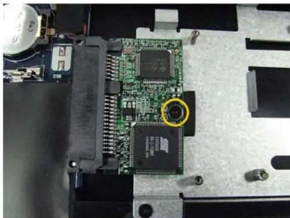
Lift the bottom cover to remove it and expose the flash module as shown in Figure 7.
-
Remove the existing flash module. Locate the flash module and use the Phillips Screwdriver to remove its retaining screw as shown in Figure 7. Lift the flash module out of the socket.
Figure 7 Removing the existing flash module
natural_image
Close-up of an electronic circuit board with a highlighted green circular component (no visible text or symbols)- Install the new flash module in the reverse order of removing the original flash module. Carefully screw down its retaining screw until it is secure.
WARNING: Flash modules may be susceptible to damage by Electro-Static Discharge (ESD). All industry-standard cautions should be followed to avoid ESD. Before you remove or install a module, touch any metal part of the chassis and keep that contact with the chassis during the installation process.
- Replace the flash cover in the reverse order as described in steps 4 and 3. CAUTION: Do not turn on the mobile thin client. The mobile thin client is ready to re-image, however the flash module does not contain an operating system. Turning on power to your mobile thin client without firmware will display the error message "NO OPERATING SYSTEM FOUND."
What's Next
Continue with "Installing Firmware."
4 Installing Z Class Flash
This chapter contains information for users of Wyse Z class thin clients who must install new flash.
Requirements
- Small Phillips screwdriver
WARNING: Flash modules may be susceptible to damage by Electro-Static Discharge (ESD). All industry-standard cautions should be followed to avoid ESD. Before you remove or install a module, touch any metal part of the chassis and keep that contact with the chassis during the installation process.
Procedures
CAUTION: Follow all precautions listed in the Quick-Start Guide that came with your thin client for disconnecting and reconnecting the thin client.
- Perform a proper shutdown of the thin client by closing all files and ending your session, and then pressing the power button to turn off the thin client.
- Unplug the power cord and power adapter, and remove any other cables from the thin client, and detach the vertical foot.
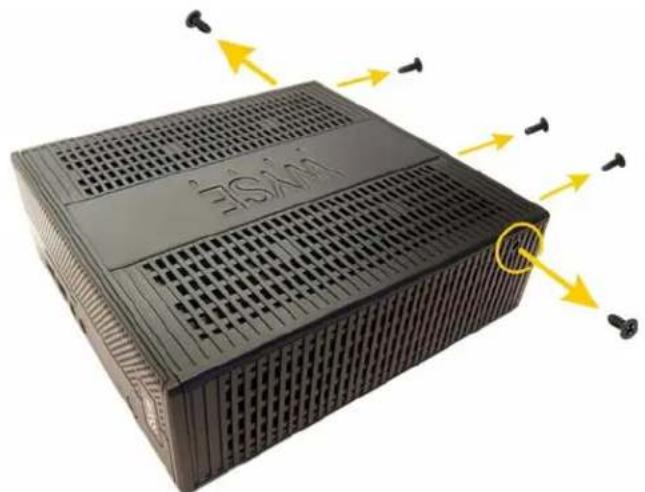
- Position the thin client horizontally, where the Wyse logo-side with four flat screws is facing downward. Using the Phillips Screwdriver remove the two screws from either end near the back panel, and then remove the three screws from the cover along the back panel edge, as shown in Figure 8.
Figure 8 Removing the cover screws
natural_image
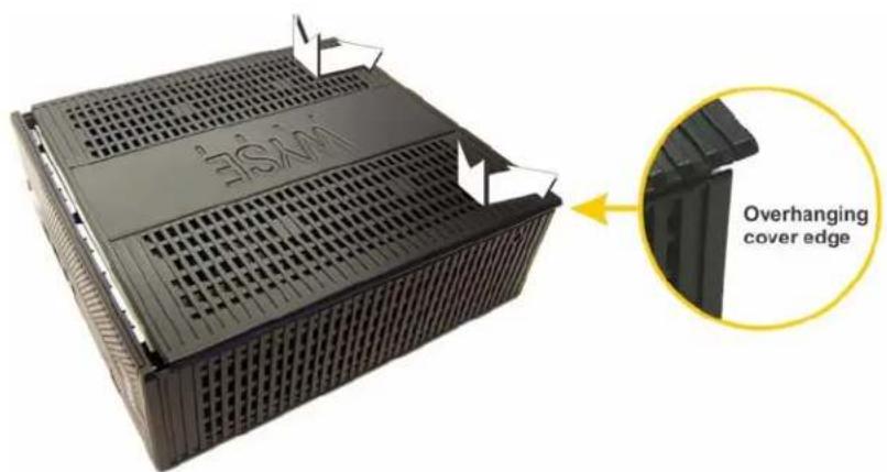
Black rectangular electronic device with ventilation grilles and yellow directional arrows indicating airflow or movement (no text or symbols)- Place your thumbs on the top surface above where the end screws were removed. With a continuous motion, push firmly downward and towards the back panel (pushing down unlatches the hooks under the cover). The cover will shift approximate 1/4 inch to hang over the back panel, as shown in Figure 9.
Figure 9 Unlatching the cover
text_image
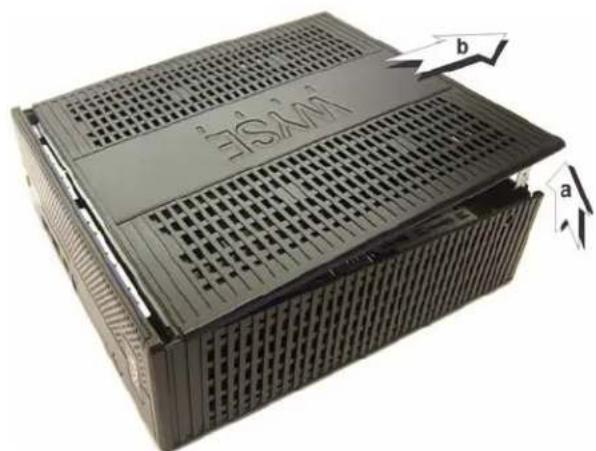
WISAM Overhanging cover edge- (a) Grasp the overhanging cover edge and raise the edge about 1-1/2 inches, and then (b) pull the cover out towards the back panel at the same angle to free the opposite end of the cover from the remaining hooks, as shown in Figure 10.
Figure 10 Removing the cover
natural_image
Black plastic container with ventilation grilles and a labeled side panel (no readable text or symbols)-
Remove the cover to expose the flash module, as shown in Figure 11.
-
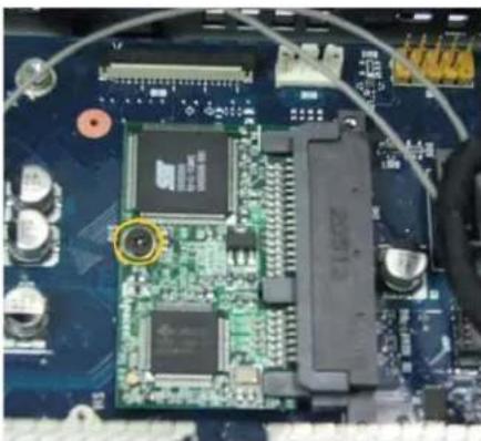
Remove the existing flash module. Locate the flash module and use the Phillips Screwdriver to remove its retaining screw as shown in Figure 11. Lift the flash module out of the socket.
Figure 11 Removing the existing flash module
natural_image
Close-up of a computer motherboard with visible circuitry and components (no readable text or symbols)- Install the new flash module in the reverse order of removing the original flash module. Carefully screw down its retaining screw until it is secure.
WARNING: Flash modules may be susceptible to damage by Electro-Static Discharge (ESD). All industry-standard cautions should be followed to avoid ESD. Before you remove or install a module, touch any metal part of the chassis and keep that contact with the chassis during the installation process.
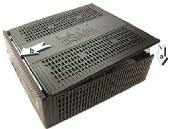
- (a) Align the cover screw tabs with screw holes and press downward; (b) slide cover toward the front of the thin client, as shown in Figure 12.
Figure 12 Reattaching the cover
natural_image
Black plastic container with perforated top and side slots, labeled 'b' and 'a' indicating orientation (no readable text or symbols beyond labels)10., Attach the screws in the reverse order as described in step 3.
- Connect the power cord and power adapter, attach any other cables to the thin client, and then attach the vertical foot.
CAUTION: Do not turn on the thin client. The thin client is ready to re-image, however the flash module does not contain an operating system. Turning on power to your thin client without firmware will display the error message "NO OPERATING SYSTEM FOUND."
What's Next
Continue with "Installing Firmware."
This page intentionally blank.
5 Installing Firmware
This chapter includes the requirements and procedures you need to install and use Wyse® USB Firmware Tool™ to update your thin client to the firmware you need.
TIP: The purpose of the Wyse USB Firmware Tool is to configure a bootable USB key for device firmware. In the following procedures, you will create a configured USB key containing the firmware contents that you need, and then boot from this configured USB key on appropriate product and flash size devices to push the contents of the USB key onto these target devices (containing your upgraded flash).
Requirements
• Machine with a minimum of 16GB of free space running either of the following:
- Windows 2003 Server
- Windows Server 2008
• Windows Server 2008 R2
- Windows 7 Enterprise (32-bit and 64-bit)
- Windows 7 Ultimate (32-bit and 64-bit)
- USB Key:
- USB 2.0 only
- USB key size should be 16 GB (see also "USB Keys - Troubleshooting Boot Issues")
CAUTION: During the USB key configuration process the USB key will be reformatted.
Procedures
IMPORTANT: Complete the following procedures as an administrator (administrator privileges are required).
Step 1: Download and Ready the Firmware You Require
You must download and ready (extract) the firmware you want to use for updating your devices before you start the Wyse USB Firmware Tool wizard. Firmware files are normally made available in .exe or .zip format and must be downloaded and then extracted to a local hard drive folder that is available to the Wyse USB Firmware Tool wizard.
Wyse provides firmware for supported devices from its Software Downloads Web site at: http://www.wyse.com/serviceandsupport/support/downloads.asp. Simply select the firmware you need in the Product Downloads Active box, click Search, and use the Active Firmware link you need.
CAUTION: For the Windows 7 operating systems, be sure to right-click on the .exe file you downloaded (for example, the BDB0_0846_4096.exe file for the D90D7 OS image) and select the Run as administrator option to extract the files.
The following are examples of the Active Firmware links that you must use (names to click) to download and extract the firmware to the local hard drive folder you want:
• D90D7 Only - BDB0_0846_4096.exe
• D90DW Only - ADA0_S727_2048.exe
• X90m7 Only - BXB8_0833_4096.exe
• X90mw Only - AXA8_S716_2048.exe
• Z90D7 and Z90S7 Only - BZB0_0830_4096.exe
• Z90DW and Z90SW Only - AZA0_S723_2048.exe
Step 2: Install Wyse USB Firmware Tool v1.18
- Download the Wyse USB Firmware Tool v1.18_GA.exe to a folder on your machine (go to http://www.wyse.com/serviceandsupport/support/downloads.asp, in the Product Downloads Active list, select USB Firmware Tool under Wyse Imaging Tools, click Search, and then download the Wyse USB Firmware Tool software).
- Double-click the Wyse USB Firmware Tool v1.18_GA.exe to execute the file and open the WinZip Self-Extractor dialog box.
- Enter the destination folder you want (for example, C:\USBFT) in the Unzip to folder box, and then click Unzip to extract all files from the Wyse USB Firmware Tool v1.18_GA.exe file into the folder. The default directory for the extracted files is Wyse USB Firmware Tool.
CAUTION: It is not recommended to use your desktop for the destination folder as there are several files that will be extracted from the .exe file. - After installation, create a shortcut on the desktop for the Wyse USB Firmware Tool.exe file (see your operating system documentation).
Step 3: Use Wyse USB Firmware Tool to Configure a Single USB Key to Install Firmware
CAUTION: For Windows 7 operating systems, be sure to right-click on Wyse USB Firmware Tool.exe and select the Run as administrator option.
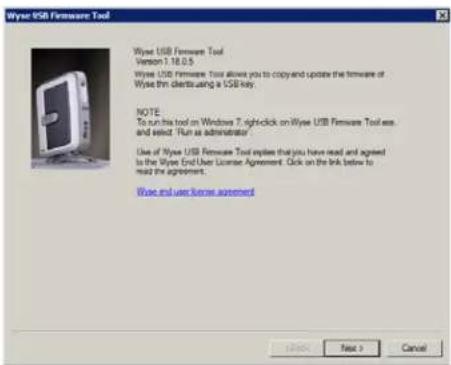
- Double-click the shortcut on the desktop for the Wyse USB Firmware Tool.exe file to run the tool and open the Wyse USB Firmware Tool wizard (the welcome page provides the product version and description, and a link to view the Wyse end user license agreement).
Figure 13 Wyse USB Firmware Tool wizard
text_image
Wynn USB Firmware Tool Version 1.18.0.5 Wynn USB Firmware Tool allows you to copy and update the firmware of Wynn thin clients using a USB key. NOTE: To run this tool on Windows 7. right-click on Wynn USB Firmware Tool was and select "Run as administrator" Use of Wynn USB Firmware Tool expires that you have read and agreed to the Wynn End User License Agreement. Click on the link below to mail the agreement. Wynn and user license agreement- Click Next to open the Select an Option dialog box.
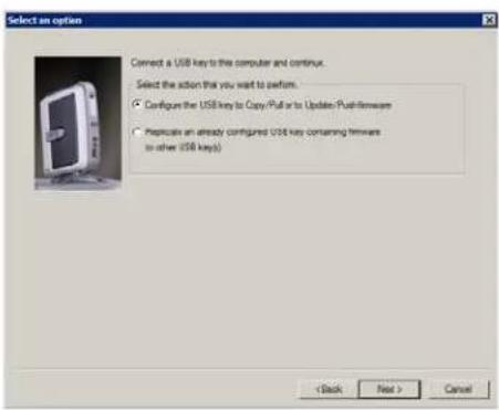
Figure 14 Configuration options
text_image
Select an option Connect a USB key to this computer and continue. Select the action that you want to perform. ● Configuring the USB key to Copy/Pull to Update Push-firmware ○ Proplicate an already configured USB key containing firmware to other USB keys() < Back Next > Cancel- Select the Configure the USB key to Copy/Pull or to Update/Push firmware option, and then click Next to open the Select the Configuration dialog box.
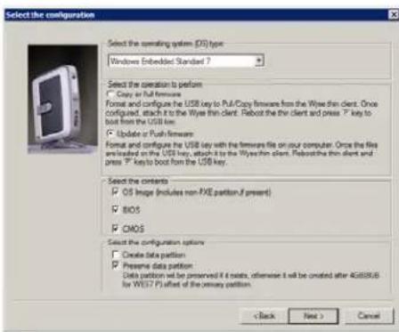
Figure 15 Update firmware options - Windows Embedded Standard 7 example
text_image
Select the configuration Select the operating system (OS) type: Windows Embedded Standard 7 Select the operation to perform □ Copy or full firmware Format and configure the USB key to Pull/Copy firmware from the Wyes thin client. Once configured, attach it to the Wyes thin client. Reboot the thin client and press T* key to boot from the USB key. □ Update or Push firmware Format and configure the USB key with the firmware file on our computer. Once the file is loaded on the USB key, attach it to the Wyes thin client. Reboot the thin client and press T* key to boot from the USB key. Select the contents □ OS Image (includes non-AVE partition if present) □ BIOS □ CMOS Select the configuration options □ Create data portion □ Preserve data portion Data portion will be preserved if it exists, otherwise it will be created after 4G08/06 for WEST P3 offset of the primary portion. < Back Next > Cancel- Depending on the operating system of the firmware (from "Step 1: Download and Ready the Firmware You Require") that you will be pushing onto the target devices (containing your upgraded flash), select one of the following OS type options:
- D90DW, X90mw, Z90DW, and Z90SW Only - Windows Embedded Standard
- D90D7, X90m7, Z90D7, and Z90S7 Only - Windows Embedded Standard 7
- Select the Update or Push Firmware operation to perform option. Be sure that all three contents options are selected (OS Image, BIOS, and CMOS). Leave the default-unselected Create data partition check box. Leave the default-selected Preserve data partition check box.
- Click Next to open the browse dialog box.
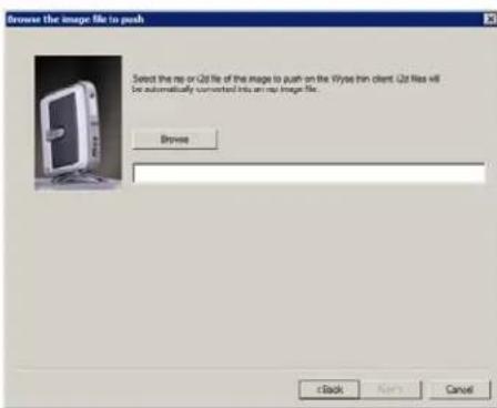
Figure 16 Browse for image file
text_image
Browse the image file to push Select the image or QD file of the image to push on the Wyes thin client. QD files will be automatically converted into an image file. Browse eBack Next Cancel- Click Browse.
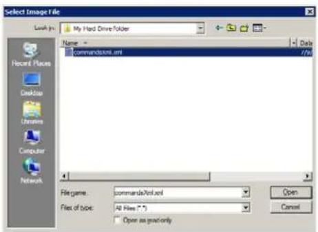
Figure 17 Browse to select commandsXml.xml example
text_image
Select Image File Look in: My Hard Drive Folder Name: commandstore.xml Date 7/9/ Recent Places Desktop Username Computer Network Filename: commandsStore.xml Files of type: All Files (*) Open as grad only Open Cancel- Navigate to the image folder (on your hard drive) that contains the firmware image you extracted (this is the location you selected in "Step 1: Download and Ready the Firmware You Require"), click on the commandsXml.xml file to select it (you may need to select the All Files option from the Files of Type box to display the commandsXml.xml file for selection), and then click Open.
CAUTION: Be sure to use the commandsXml.xml file you extracted in "Step 1: Download and Ready the Firmware You Require"; do not use the commandsXml.xml file directly from an .exe or .zip download.
- In the browse dialog box, click Next to open the Prepare the USB Drive dialog box.
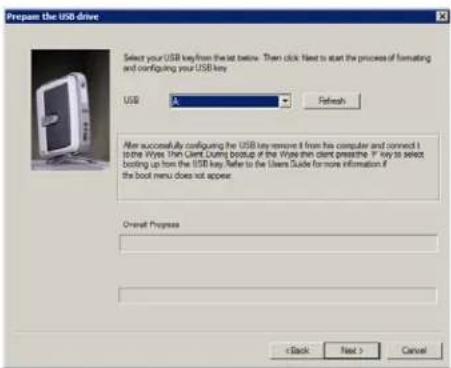
Figure 18 Prepare USB key for configuration
text_image
Prepare the USB drive Select your USB key from the list before. Then click Next to start the process of formatting and configuring your USB key. USB A Refresh After successfully configuring the USB key remove it from his computer and connect it to the Wires Then Client Linux backup of the Wires then client pressfree. If you want to select booting up from the USB key. Refer to the Users Guide for more information if the boot menu does not appear. Overall Progress < Back Next > Cancel- Select the USB key onto which you want the configurations (you can use Refresh as needed to recognize an inserted USB key), and then click Next. The progress bars show the overall (formatting and configuration) progress and task progress.
CAUTION: DO NOT interrupt the formatting and configuration process. All process requirements are done automatically. The progress screen may display for several seconds or longer. You can safely ignore any error message.
- After configuration, click Finish to close the wizard and then remove the configured USB key for use (you will use the configured USB key on your target devices).
TIP: At this time you can also replicate/duplicate the configured USB key (containing the firmware you want to push) for simultaneous usage on target devices (by users in several locations at the same time). For full Wyse USB Firmware Tool details, see Users Guide: Wyse® USB Firmware Tool 1.18.
Step 4: Use the Configured USB Key to Install Firmware on Each Thin Client
On each thin client you want to convert, you must configure it to boot from the configured USB key.
Depending on your device, use the following guidelines:
- For D90D7 and D90DW thin clients:
- You must change the BIOS Setup Utility (you do not need to restore your settings later, as the new firmware will restore default settings automatically after you start your thin client): Be sure the client is shut down and disconnected from any network. Attach the configured USB key to the thin client. During boot, press and hold the Delete key. Enter the password Fireport (this is case sensitive) and press Enter. Select the Advanced tab. Using the down arrow key, select the Boot from USB option and press Enter. Select the Enabled option and press Enter. Press the F10 key, and then press y to save the BIOS settings and reboot. Follow the process prompts.
- For X90m7 and X90mw mobile thin clients:
- You must change the BIOS Setup Utility (you can restore your settings later in "Step 5: Verifying Thin Client Operation"): Be sure the client is shut down and disconnected from any network. Attach the configured USB key to the mobile client. During boot, press and hold the F2 key. Enter the password Fireport (this is case sensitive) and press Enter. Select the Boot option and press Enter. Select the Legacy option and press Enter. Select the Normal Boot Menu option and press Enter. Select the option displaying your USB key vendor name and move it to the 1 position by using the + key. Save the BIOS settings and reboot. Follow the process prompts.
- For Z90D7, Z90S7 Z90DW, and Z90SW thin clients:
- You must use the one-time boot menu (the one-time boot menu will not modify your default BIOS configurations): Be sure the client is shut down and disconnected from any network. Attach the configured USB key to the thin client. During boot, press and hold the P key. Select the USB HDD option (displaying your USB key vendor name) and press Enter. Follow the process prompts.
TIP: When booting a target device from the configured USB key (containing the contents to be pushed to a target device), you will be prompted to continue with the push process (to continue, type y and press Enter). Once the push process is complete, you will be prompted to reboot (to reboot, press Enter and remove the USB key).
CAUTION: During the Critical Operation in Progress message, do not interrupt the process.
TIP: You can use the configured USB key to push the firmware onto as many target devices as you want (repeat "Step 4: Use the Configured USB Key to Install Firmware on Each Thin Client").
Step 5: Verifying Thin Client Operation
After the thin client reboots, you can verify your general client information. For example, the Client Information dialog box (D class), or the System Information dialog box (X class and Z class) information is correct (that the new Flash is correctly recognized by the system). After verification, the thin client is ready for operation and setup by an administrator.
TIP: Administrator and other documentation for your thin client model are available at: http://www.wyse.com/manuals.
CAUTION: For X90m7 and X90mw mobile thin clients, you can change the BIOS Setup Utility back to its original state.
Troubleshooting
This section contains general troubleshooting information.
USB Keys - Troubleshooting Boot Issues
Due to different manufacturing processes on USB keys (and the variety of them), not all brands have been tested with the Wyse USB Firmware Tool. If you experience problems booting from a configured USB key, it is recommended that you try a different brand of USB key.
SanDisk Cruiser Flash Drives - Troubleshooting Partition Issues
Problem: How can I properly use a SanDisk Cruiser flash drive to image supported devices using the Wyse USB Firmware Tool? (KB17735)
Solution: SanDisk flash drives come with support for U3 (for details on U3, see http://www.u3.com). When you initially use these drives, you are prompted to select the use for the drive: Apps and Storage or only Storage. If you select the Apps and Storage option, the drive will create two partitions, one of which is identified as a CD and is a read only partition. This partition sometimes prevents the Wyse USB Firmware Tool to properly prepare the USB key for imaging a device. To resolve this problem you can do one of the following:
- Go to http://www.sansearchin the SanDisk Knowledge Base for document 2550, and then follow the instructions in the documentation.
- Go to http://www.sandisk.com/DriverDownload/driveselectUSB Flash Drives from the Select Product Type list, click Find Driver, select U3 LaunchPad Remover, click Continue, and then download and use the U3 Launchpad Remover according to the instructions.
Installation Guide
Wyse® D Class, Wyse® X Class, and Wyse® Z Class Flash Upgrade Option Kit Issue: 011613
Written and published by:
Wyse Technology Inc., January 2013
Created using FrameMaker ^® and Acrobat ^®