
PowerEdge R720xd - Server DELL - Free user manual and instructions
Find the device manual for free PowerEdge R720xd DELL in PDF.


User questions about PowerEdge R720xd DELL
0 question about this device. Answer the ones you know or ask your own.
Ask a new question about this device
Download the instructions for your Server in PDF format for free! Find your manual PowerEdge R720xd - DELL and take your electronic device back in hand. On this page are published all the documents necessary for the use of your device. PowerEdge R720xd by DELL.
USER MANUAL PowerEdge R720xd DELL
Dell PowerEdge R720 and R720xd
Owner's Manual
Notes, Cautions, and Warnings
NOTE: A NOTE indicates important information that helps you make better use of your computer.
CAUTION: A CAUTION indicates either potential damage to hardware or loss of data and tells you how to avoid the problem.
WARNING: A WARNING indicates a potential for property damage, personal injury, or death.
Copyright © 2014 Dell Inc. All rights reserved. This product is protected by U.S. and international copyright and intellectual property laws. Dell™ and the Dell logo are trademarks of Dell Inc. in the United States and/or other jurisdictions. All other marks and names mentioned herein may be trademarks of their respective companies.
Contents
1 About Your System....8
Front-Panel Features And Indicators....8
LCD Panel Features....11
Home Screen....12
Setup Menu....12
View Menu....12
Diagnostic Indicators....13
Hard-Drive Indicator Patterns....15
Back-Panel Features And Indicators....16
NIC Indicator Codes....17
Power Indicator Codes....18
Other Information You May Need....19
2 Using The System Setup and Boot Manager....20
Choosing The System Boot Mode....21
Entering System Setup....21
Responding To Error Messages.... 21
Using The System Setup Navigation Keys....21
System Setup Options....22
System Setup Main Screen....22
System BIOS Screen....22
System Information Screen....23
Memory settings screen....23
Processor Settings Screen.... 24
SATA Settings Screen.... 25
Boot Settings Screen.... 25
Integrated devices screen....26
Serial Communications Screen....27
System Profile Settings Screen....27
System Security Screen....28
Miscellaneous Settings....29
System And Setup Password Features....29
Assigning A System And/Or Setup Password.... 30
Deleting Or Changing An Existing System And/Or Setup Password....30
Using Your System Password To Secure Your System.... 31
Operating With A Setup Password Enabled....31
Entering The UEFI Boot Manager....32
Using The Boot Manager Navigation Keys....32
Boot Manager Screen.... 32
UEFI Boot Menu....33
Embedded System Management....33
iDRAC Settings Utility....33
Entering The iDRAC Settings Utility....33
Changing The Thermal Settings....33
3 Installing System Components....35
Recommended Tools....35
Front Bezel (Optional)....36
Removing The Front Bezel....36
Installing The Front Bezel....36
Opening And Closing The System....36
Opening The System....37
Closing The System....37
Inside The System....38
Cooling Shroud....39
Removing The Cooling Shroud....39
Installing The Cooling Shroud....40
System memory....40
General Memory Module Installation Guidelines....42
Mode-Specific Guidelines....43
Sample memory configurations....44
Removing Memory Modules....47
Installing Memory Modules....48
Hard Drives....49
Removing A 2.5 Inch Hard-Drive Blank....50
Installing A 2.5 Inch Hard-Drive Blank....50
Removing A 2.5 Inch Hard-Drive Blank (Back)....50
Installing A 2.5 Inch Hard-Drive Blank (Back)....51
Removing A 3.5 Inch Hard-Drive Blank....51
Installing A 3.5 Inch Hard-Drive Blank....52
Removing A Hot-Swap Hard Drive....52
Installing A Hot-Swap Hard Drive....52
Removing A Hard Drive From A Hard-Drive Carrier....53
Installing A Hard Drive Into A Hard-Drive Carrier....54
Optical Drive (Optional)....54
Removing The Optical Drive....54
Installing The Optical Drive....55
Cooling Fans....55
Removing A Cooling Fan....56
Installing A Cooling Fan....56
Removing The Cooling-Fan Assembly....57
Installing The Cooling-Fan Assembly....58
Internal USB Memory Key (Optional)....58
Replacing The Internal USB Key....58
PCIe Card Holder....59
Removing The PCIe Card Holder....59
Installing The PCIe Card Holder....60
Opening And Closing The PCIe Card Holder Latch....60
Top Cover Lock Latch....61
Installing The Top Cover Lock Latch....61
Cable Retention Bracket....62
Removing The Cable Retention Bracket....62
Installing The Cable Retention Bracket....63
Expansion Cards And Expansion-Card Risers....63
Expansion Card Installation Guidelines....63
Removing An Expansion Card From The Expansion-Card Riser 2 Or 3....65
Installing An Expansion Card Into The Expansion-Card Riser 2 Or 3....66
Removing An Expansion Card From The Expansion-Card Riser 1....67
Installing An Expansion Card Into The Expansion-Card Riser 1....68
Removing Expansion-Card Risers....69
Installing Expansion-Card Risers....72
GPU Card Installation Guidelines....72
Installing A GPU Card....73
Removing A GPU Card....74
SD vFlash Card....75
Replacing An SD vFlash Card....75
Removing The vFlash Media Unit....76
Installing The vFlash Media Unit....77
Internal Dual SD Module....77
Removing The Internal Dual SD Module....78
Installing The Internal Dual SD Module....79
Internal SD Card....79
Removing An Internal SD Card....79
Installing An Internal SD Card....79
Integrated Storage Controller Card....80
Removing The Integrated Storage Controller Card....80
Installing The Integrated Storage Controller Card....81
Network Daughter Card....81
Removing The Network Daughter Card....82
Installing The Network Daughter Card....82
Processors....83
Removing A Processor....83
Installing A Processor....86
Power Supplies 87
Hot Spare Feature....88
Removing An AC Power Supply....88
Installing An AC Power Supply 89
Wiring Instructions For A DC Power Supply....89
Removing A DC Power Supply....91
Installing A DC Power Supply....92
Removing The Power Supply Blank....93
Installing The Power Supply Blank....93
System Battery....93
Replacing The System Battery....93
Hard-Drive Backplane....94
Removing The Hard-Drive Backplane....95
Installing The Hard-Drive Backplane....106
Removing The Optional Hard-Drive Backplane (Back)....107
Installing The Optional Hard-Drive Backplane (Back)....108
Control Panel Board....109
Removing The Control Panel (PowerEdge R720)....109
Installing The Control Panel (PowerEdge R720)....110
Removing The Control Panel (PowerEdge R720xd)....111
Installing The Control Panel (PowerEdge R720xd)....112
Removing The I/O Panel (PowerEdge R720xd)....112
Installing The I/O Panel (PowerEdge R720xd)....113
System Board....114
Removing The System Board....114
Installing The System Board....115
4 Troubleshooting Your System....117
Safety First—For You And Your System....117
Troubleshooting System Startup Failure....117
Troubleshooting External Connections....118
Troubleshooting The Video Subsystem....118
Troubleshooting A USB Device....118
Troubleshooting A Serial I/O Device....118
Troubleshooting A NIC....118
Troubleshooting A Wet System....119
Troubleshooting A Damaged System....120
Troubleshooting The System Battery....120
Troubleshooting Power Supplies....120
Troubleshooting Cooling Problems....121
Troubleshooting Cooling Fans....121
Troubleshooting System Memory....121
Troubleshooting An Internal USB Key....122
Troubleshooting An SD Card....122
Troubleshooting An Optical Drive....123
Troubleshooting A Tape Backup Unit....123
Troubleshooting A Hard Drive....124
Troubleshooting A Storage Controller....124
Troubleshooting Expansion Cards.... 125
Troubleshooting Processors....125
5 Using system diagnostics.... 126
Dell Online Diagnostics....126
Dell Embedded System Diagnostics....126
When To Use The Embedded System Diagnostics....126
Running The Embedded System Diagnostics.... 127
System Diagnostic Controls....127
6 Jumpers And Connectors.... 128
System Board Jumper Settings....128
System Board Connectors....129
Disabling A Forgotten Password....131
7 Technical Specifications....132
8 System Messages....137
LCD Messages....137
Viewing LCD Messages....137
Removing LCD Messages....137
System Error Messages....137
Warning Messages....150
Diagnostic Messages....150
Alert Messages....150
9 Getting Help.... 151
Contacting Dell....151
About Your System
Topics:
- Front-Panel Features And Indicators
- LCD Panel Features
• Diagnostic Indicators
• Hard-Drive Indicator Patterns - Back-Panel Features And Indicators
• NIC Indicator Codes
• Power Indicator Codes
• Other Information You May Need
Front-Panel Features And Indicators
text_image
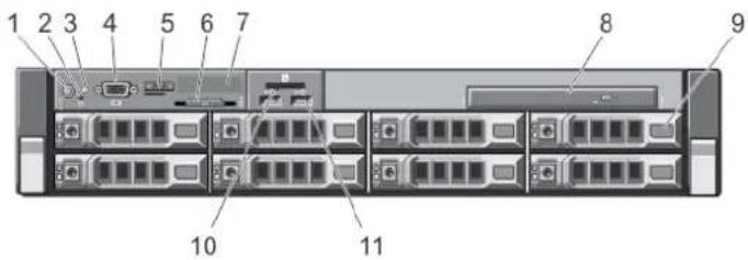
1 2 3 4 5 6 7 8 9 10 11Figure 1. Front-Panel Features and Indicators (3.5 Inch Chassis)—PowerEdge R720
text_image
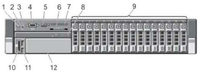
1 2 3 4 5 6 7 8 9 10 11 12Figure 2. Front-Panel Features and Indicators (2.5 Inch Chassis)—PowerEdge R720
Item Indicator, Button, or Connector Icon Description
| 1 Power-on indicator, power button | ∅ | The power-on indicator lights when the system power is on. The power button controls the power supply output to the system. |
Item Indicator, Button, or Connector Icon Description
| 1 | NOTE: On ACPI-compliant operating systems, turning off the system using the power button causes the system to perform a graceful shutdown before power to the system is turned off. | ||
| 2 NMI button | ⊗ | Used to troubleshoot software and device driver errors when running certain operating systems. This button can be pressed using the end of a paper clip.Use this button only if directed to do so by qualified support personnel or by the operating system's documentation. | |
| 3 | System identification button | i | The identification buttons on the front and back panels can be used to locate a particular system within a rack. When one of these buttons is pressed, the LCD panel on the front and the system status indicator on the back flashes until one of the buttons is pressed again.Press to toggle the system ID on and off.If the system stops responding during POST, press and hold the system ID button for more than five seconds to enter BIOS progress mode.To reset iDRAC (if not disabled in F2 iDRAC setup) press and hold the button for more than 15 seconds. |
| 4 Video connector Allows you to connect a VGA display to the system. | |||
| 5 LCD menu buttons Allows you to navigate the control panel LCD menu. | |||
| 6 Information tag A slide-out label panel which allows you to record system information such as Service Tag, NIC, MAC address and so on as per your need. | |||
| 7 LCD panel Displays system ID, status information, and system error messages.The LCD lights blue during normal system operation. The LCD lights amber when the system needs attention, and the LCD panel displays an error code followed by descriptive text. | |||
| 8 Optical drive (optional) One optional SATA DVD-ROM drive or DVD+/-RW drive. | |||
| 9 Hard drives | 3.5 inch hard drive systems | Up to eight 3.5 inch hot-swappable drives. | |
| 2.5 inch hard drive systems | Up to sixteen 2.5 inch hot-swappable hard drives. | ||
i
NOTE: In systems supporting Dell PowerEdge Express Flash devices (PCIe SSDs), hard-drive slots 0 through 3 in hard-drive bay 2 support only PCIe SSDs. Hard-drive bay 3 does not support any hard drives and is installed with a hard-drive blank.
10 vFlash media card slot Allows you to insert a vFlash media card.
11 USB connectors (2) Allows you to connect USB devices to the system. The ports are USB 2.0-compliant.
12 Tape drive slot (optional) One optional 3.5 inch tape backup unit.
text_image
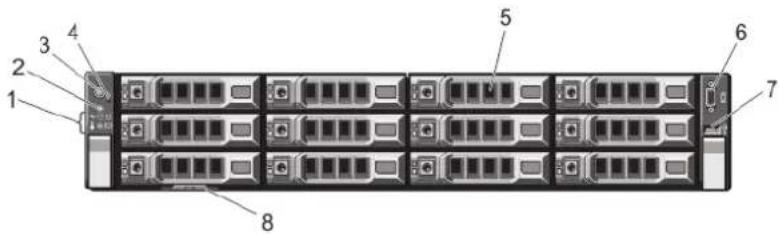
Diagram of a rack-mounted server rack with numbered components for identificationFigure 3. Front-Panel Features and Indicators (3.5 Inch Chassis)—PowerEdge R720xd

text_image
1 2 3 4 5 6 7 8 9 10 11 12 13 14 15 16 17 18 19 20 21 22 23 24 25 26 27 28 29 30 31 32 33 34 35 36 37 38 39 40Figure 4. Front-Panel Features and Indicators (2.5 Inch Chassis)—PowerEdge R720xd
Item Indicator, Button, or Connector Icon Description
| 1 Diagnostic indicators The diagnostic indicators light up to display error status. | ||
| 2 | System identification button | The identification buttons on the front and back panels can be used to locate a particular system within a rack. When one of these buttons is pressed, the system status indicator on the back flashes until one of the buttons is pressed again.Press to toggle the system ID on and off.If the system stops responding during POST, press and hold the system ID button for more than five seconds to enter BIOS progress mode.To reset the iDRAC (if not disabled in F2 iDRAC setup) press and hold the button for more than 15 seconds. |
Item Indicator, Button, or Connector Icon Description
| 3 Power-on indicator, power button | The power-on indicator lights when the system power is on. The power button controls the power supply output to the system. | |
| NOTE: On ACPI-compliant operating systems, turning off the system using the power button causes the system to perform a graceful shutdown before power to the system is turned off. | ||
| 4 NMI button Used to troubleshoot software and device driver errors when running certain operating systems. This button can be pressed using the end of a paper clip.Use this button only if directed to do so by qualified support personnel or by the operating system's documentation. | ||
| 5 Hard drives | 3.5 inch hard drive systems | Up to twelve 3.5 inch hot-swappable hard drives. |
| 2.5 inch hard drive systems | Up to twenty-four 2.5 inch hot-swappable hard drives. | |
| 6 Video connector Allows you to connect a VGA display to the system. | ||
| 7 USB connector Allows you to connect USB devices to the system. The port is USB 2.0-compliant. | ||
| 8 Information tag A slide-out label panel which allows you to record system information such as Service Tag, NIC, MAC address, and so on as per your need. | ||
LCD Panel Features

NOTE: The LCD panel is present only on PowerEdge R720.
The system's LCD panel provides system information and status and error messages to indicate when the system is operating correctly or when the system needs attention. See System Error Messages for information about specific error codes.
- The LCD backlight lights blue during normal operating conditions and lights amber to indicate an error condition.
- The LCD backlight is off when the system is in standby mode and can be turned on by pressing either the Select, Left, or Right button on the LCD panel.
• The LCD backlight remains off if LCD messaging is turned off through the iDRAC utility, the LCD panel, or other tools.
text_image
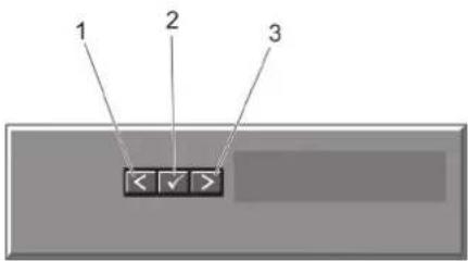
1 2 3Figure 5. LCD Panel Features
Item Button Description
| 1 Left Moves the cursor back in one-step | increments. |
| 2 Select Selects the menu item highlighted by the | cursor. |
| 3 Right Moves the cursor forward in one-step | increments.During message scrolling:Press once to increase scrolling speedPress again to stopPress again to return to default scrolling speedPress again to repeat the cycle |
Home Screen
The Home screen displays user-configurable information about the system. This screen is displayed during normal system operation when there are no status messages or errors. When the system is in standby mode, the LCD backlight turns off after five minutes of inactivity if there are no error messages. Press one of the three navigation buttons (Select, Left, or Right) to view the Home screen.
To navigate to the Home screen from another menu, continue to select the up arrow ↑ until the Home icon ↑ is displayed, and then select the Home icon.
From the Home screen, press the Select button to enter the main menu.
Setup Menu
NOTE: When you select an option in the Setup menu, you must confirm the option before proceeding to the next action.
Option Description
| iDRAC | Select DHCP or Static IP to configure the network mode. If Static IP is selected, the available fields are IP.Subnet (Sub), and Gateway (Gtw). Select Setup DNS to enable DNS and to view domain addresses. Two separate DNS entries are available. |
| Set error | Select SEL to display LCD error messages in a format that matches the IPMI description in the SEL. This is useful when trying to match an LCD message with an SEL entry.Select Simple to display LCD error messages in a simplified user-friendly description. See System Error Messages for a list of messages in this format. |
| Set home | Select the default information to be displayed on the LCD Home screen. See View Menu to see the options and option items that can be set as the default on the Home screen. |
View Menu
NOTE: When you select an option in the View menu, you must confirm the option before proceeding to the next action.
Option Description
| iDRAC IP | Displays the IPv4 or IPv6 addresses for the iDRAC7. Addresses include DNS (Primary and Secondary), Gateway, IP, and Subnet (IPv6 does not have Subnet). |
| MAC | Displays the MAC addresses for iDRAC, iSCSI, or Network devices. |
| Name | Displays the name of the Host, Model, or User String for the system |
| Number | Displays the Asset tag or the Service tag for the system. |
| Power | Displays the power output of the system in BTU/hr or Watts. The display format can be configured in the Sethome submenu of the Setup menu. |
| Temperature | Displays the temperature of the system in Celsius or Fahrenheit. The display format can be configured in the Sethome submenu of the Setup menu. |
Diagnostic Indicators
NOTE: The diagnostic indicators are present only on PowerEdge R720xd.
The diagnostic indicators on the system front panel display error status during system startup.
NOTE: No diagnostic indicators are lit when the system is switched off. To start the system, plug it into a working power source and press the power button.
The following section describes system conditions and possible corrective actions associated with these indicators:

Health indicator
Condition Corrective Action
If the system is on, None required. and in good health, the indicator lights solid blue.
The indicator blinks amber if the system is on or in standby, and any error exists (for example, a failed fan or hard drive)
See the System Event Log or system messages for the specific issue.
Invalid memory configurations can cause the system to halt at startup without any video output. See Getting Help.

Hard-drive indicator
Condition Corrective Action
The indicator blinks amber if a hard drive experiences an error.
See the System Event Log to determine the hard drive that has an error. Run the appropriate Online Diagnostics test. Restart system and run embedded diagnostics (ePSA). If the hard drives are configured in a RAID array, restart the system and enter the host adapter configuration utility program.

Electrical indicator
Condition Corrective Action
The indicator blinks amber if the system experiences an electrical error (for example, voltage out of range, or a failed power supply or voltage regulator).
See the System Event Log or system messages for the specific issue. If it is due to a problem with the power supply, check the LED on the power supply. Re-seat the power supply by removing and reinstalling it. If the problem persists, see Getting Help.

Temperature indicator
Condition Corrective Action
The indicator blinks amber if the system experiences a thermal error (for example, a temperature out of range or fan failure).
Ensure that none of the following conditions exist:
- A cooling fan is removed or has failed.
- System cover, cooling shroud, EMI filler panel, memory-module blank, or back-filler bracket is removed.
- Ambient temperature is too high.
- External airflow is obstructed.
See Getting Help.

Memory indicator
Condition Corrective Action
The indicator blinks amber if a memory error occurs.
See the system event log or system messages for the location of the failed memory. Reinstall the memory device. If the problem persists, see Getting Help.

PCIe indicator
Condition Corrective Action
The indicator blinks amber if a PCIe card experiences an error.
Restart the system. Update any required drivers for the PCIe card. Re-install the card. If the problem persists, see Getting Help.
Hard-Drive Indicator Patterns
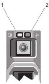
text_image
Diagram of a device with labeled parts 1 and 2, showing a camera and display screen.Figure 6. Hard-Drive Indicators
1 hard-drive activity indicator (green) 2 hard-drive status indicator (green and amber)

NOTE: If the hard drive is in Advanced Host Controller Interface (AHCI) mode, the status indicator (on the right side) does not function and remains off.
Drive-Status
Condition
Indicator Pattern
(RAID Only)
Blinks green two
Identifying drive or preparing for removal
times per second
OffDrive ready for insertion or removal

NOTE: The drive status indicator remains off until all hard drives are initialized after the system is turned on. Drives are not ready for insertion or removal during this time.
Blinks green, amber, and off
Predicted drive failure
Blinks amber four times per second
Drive failed
Blinks green slowly Drive rebuilding
Steady green Drive online
Blinks green three
Rebuild aborted
seconds, amber
three seconds, and
off six seconds
Back-Panel Features And Indicators
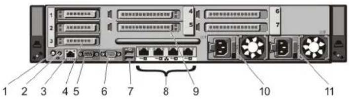
text_image
1 2 3 4 5 6 7 8 9 10 11Figure 7. Back-Panel Features and Indicators—PowerEdge R720
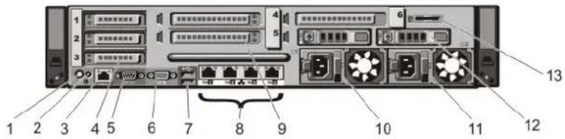
text_image
1 2 3 4 5 6 7 8 9 10 11 12 13Figure 8. Back-Panel Features and Indicators—PowerEdge R720xd
Item Indicator, Button, or Connector Icon Description
| 1 | System identification button | The identification buttons on the front and back panels can be used to locate a particular system within a rack.PowerEdge R720 When one of these buttons is pressed, the LCD panel on the front and the system status indicator on the back flashes until one of the buttons is pressed again.PowerEdge R720xd When one of these buttons is pressed, the system status indicator on the back flashes until one of the buttons is pressed again.Press to toggle the system ID on and off.If the system stops responding during POST, press and hold the system ID button for more than five seconds to enter BIOS progress mode.To reset iDRAC (if not disabled in F2 iDRAC setup) press and hold the button for more than 15 seconds. |
| 2 | System identification connector | Connects the optional system status indicator assembly through the optional cable management arm. |
| 3 iDRAC7 Enterprise port Dedicated management port. | NOTE: The port is available for use only if the iDRAC7 Enterprise license is installed on your system. | |
| 4 PCIe expansion card slots low-profile (3) | Allows you to connect up to three PCI Express expansion cards. | |
| 5 Serial connector Allows you to connect a serial device to the system. | ||
Item Indicator, Button, or Connector Icon Description
| 6 Video connector Allows you to connect a VGA display to the system. | ||
| 7 USB connectors (2) Allows you to connect USB devices to the system. The ports are USB 2.0-compliant. | ||
| 8 Ethernet connectors Four integrated 10/100/1000 Mbps NIC connectors or Four integrated connectors that include: · Two 10/100/1000 Mbps NIC connectors · Two 100 Mbps/1 Gbps/10 Gbps SFP+/10 GbE T connectors | ||
| 9 PCIe expansion card slots full height (4) (PowerEdge R720) | Allows you to connect up to four full-height PCI Express expansion cards. | |
| PCIe expansion card slots full height (3) (PowerEdge R720xd) | ||
| 10 Power supply (PSU1) | AC 495 W, 750 W, or 1100 W | |
| 11 Power supply (PSU2) | or DC 750 W, or 1100 W | |
| 12 | Hard drives (2) (back) | Up to two hot-swappable 2.5 inch hard drives. |
| 13 | vFlash media card slot | Allows you to insert a vFlash media card. |
NIC Indicator Codes
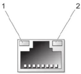
text_image
1 2Figure 9. NIC Indicator
1 link indicator
2 activity indicator
Indicator Indicator Code
Link and activity indicators are off The NIC is not connected to the network.
Link indicator is green The NIC is connected to a valid network at its maximum port speed (1 Gbps or 10 Gbps).
Link indicator is amber The NIC is connected to a valid network at less than its maximum port speed.
Indicator Indicator Code
Activity indicator is Network data is being sent or received.
blinking green
Power Indicator Codes
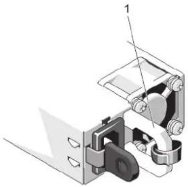
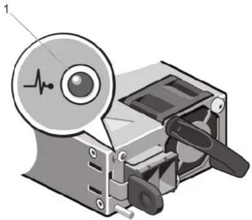
Each AC power supply has an illuminated translucent handle and each DC power supply (when available) has an LED that serves as an indicator to show whether power is present or whether a power fault has occurred.
natural_image
Mechanical assembly diagram showing a bracket with mounting holes and a labeled component (no text or symbols present)Figure 10. AC Power Supply Status Indicator
1 AC power supply status indicator/handle
natural_image
Illustration of a mechanical device with an ECG indicator and a magnified inset showing internal components (no text or symbols)Figure 11. DC Power Supply Status Indicator
1 DC power supply status indicator
Power Indicator Condition
Pattern
Not lit Power is not connected.
Green The handle/LED indicator lights green indicating that a valid power source is connected to the power supply and that the power supply is operational.
Flashing amber Indicates a problem with the power supply.
Power Indicator Condition Pattern
CAUTION: When correcting a power supply mismatch, replace only the power supply with the flashing indicator. Swapping the opposite power supply to make a matched pair can result in an error condition and unexpected system shutdown. To change from a High Output configuration to a Low Output configuration or vice versa, you must power down the system.
CAUTION: AC power supplies support both 220 V and 110 V input voltages with the exception of Titanium power supplies, which support only 220 V. When two identical power supplies receive different input voltages, they can output different wattages, and trigger a mismatch.
CAUTION: If two power supplies are used, they must be of the same type and have the same maximum output power.
CAUTION: Combining AC and DC power supplies is not supported and triggers a mismatch.
Flashing green
When hot-adding a power supply, this indicates that the power supply is mismatched with the other power supply (in terms of efficiency, feature set, health status, and supported voltage). Replace the power supply that has the flashing indicator with a power supply that matches the capacity of the other installed power supply.
Other Information You May Need

WARNING: See the safety and regulatory information that shipped with your system. Warranty information may be included within this document or as a separate document.
- The Getting Started Guide provides an overview of setting up your system, and technical specifications. This document is available online at dell.com/support/manuals.
- The rack documentation included with your rack solution describes how to install your system into a rack, if required.
- Any media that ships with your system that provides documentation and tools for configuring and managing your system, including those pertaining to the operating system, system management software, system updates, and system components that you purchased with your system.
• For the full name of an abbreviation or acronym used in this document, see the Glossary at dell.com/support/manuals.

NOTE: Always check for updates on dell.com/support/manuals and read the updates first because they often supersede information in other documents.
Using The System Setup and Boot Manager
System Setup enables you to manage your system hardware and specify BIOS-level options.
The following keystrokes provide access to system features during startup:
| Keystroke | Description |
| Opens the System Setup page. | |
| Enters System Services and starts Lifecycle Controller, which supports systems management features such as operating system deployment, hardware diagnostics, firmware updates, and platform configuration, using a graphical user interface. The feature set available in Lifecycle Controller is determined by the iDRAC license purchased. For more information, see Related Documentation topic. | |
| Enters the BIOS Boot Manager or the Unified Extensible Firmware Interface (UEFI) Boot Manager, depending on the system's boot configuration. | |
| Starts Preboot Execution Environment (PXE) boot. |
From the System Setup, you can:
- Change the NVRAM settings after you add or remove hardware
• View the system hardware configuration - Enable or disable integrated devices
- Set performance and power management thresholds
- Manage system security
You can access the System Setup using the:
- Standard graphical browser, which is enabled by default
- Text browser, which is enabled using Console Redirection
To enable Console Redirection, in System Setup, select System BIOS > Serial Communication screen > Serial Communication, select On with Console Redirection.

NOTE By default, help text for the selected field is displayed in the graphical browser. To view the help text in the text browser, press
Topics:
- Choosing The System Boot Mode
- Entering System Setup
- System Setup Options
- System And Setup Password Features
- Entering The UEFI Boot Manager
- Embedded System Management
Choosing The System Boot Mode
System Setup enables you to specify the boot mode for installing your operating system:
- BIOS boot mode (the default) is the standard BIOS-level boot interface.
- UEFI boot mode is an enhanced 64-bit boot interface based on Unified Extensible Firmware Interface (UEFI) specifications that overlays the system BIOS.
You must select the boot mode in the Boot Mode field of the Boot Settings screen of System Setup. Once you specify the boot mode, the system boots in the specified boot mode and you then proceed to install your operating system from that mode. Thereafter, you must boot the system in the same boot mode (BIOS or UEFI) to access the installed operating system. Trying to boot the operating system from the other boot mode will cause the system to halt at startup.
NOTE: Operating systems must be UEFI-compatible to be installed from the UEFI boot mode. DOS and 32-bit operating systems do not support UEFI and can only be installed from the BIOS boot mode.
NOTE: For the latest information on supported operating systems, go to dell.com/ossupport.
Entering System Setup
1 Turn on or restart your system.
2 Press
<F2> = System Setup
If your operating system begins to load before you press
Responding To Error Messages
If an error message is displayed while the system is booting, make a note of the message. For more information, see System Error Messages.
NOTE After installing a memory upgrade, it is normal for your system to display a message the first time you start your system.
Using The System Setup Navigation Keys
Keys
Action
Up arrow Moves to the previous field.
Down arrow Moves to the next field.
Allows you to type in a value in the selected field (if applicable) or follow the link in the field.
Spacebar Expands or collapses a drop-down menu, if applicable.
NOTE: For the standard graphics browser only.
Moves to the previous page till you view the main screen. Pressing
NOTE: For most of the options, any changes that you make are recorded but do not take effect until you restart the system.
System Setup Options
System Setup Main Screen
NOTE: Press
Menu Item Description
System BIOS This option is used to view and configure BIOS settings.
iDRAC Settings This option is used to view and configure iDRAC settings.
Device Settings This option is used to view and configure device settings.
System BIOS Screen
NOTE: The options for System Setup change based on the system configuration.
NOTE: System Setup defaults are listed under their respective options in the following sections, where applicable.
Menu Item Description
System Information Displays information about the system such as the system model name, BIOS version, Service Tag, and so on.
Memory Settings Displays information and options related to installed memory.
Processor Settings Displays information and options related to the processor such as speed, cache size, and so on.
SATA Settings Displays options to enable or disable the integrated SATA controller and ports.
NOTE: This setting is not available on the PowerEdge R720xd.
Boot Settings Displays options to specify the boot mode (BIOS or UEFI). Enables you to modify UEFI and BIOS boot settings.
Integrated Devices Displays options to enable or disable integrated device controllers and ports, and to specify related features and options.
Serial Displays options to enable or disable the serial ports and specify related features and options.
Communication
System Profile Displays options to change the processor power management settings, memory frequency, and so on.
Settings
System Security Displays options to configure the system security settings like, system password, setup password, TPM security, and so on. It also enables or disables support for local BIOS update, the power and NMI buttons on the system.
Miscellaneous Displays options to change the system date, time, and so on.
Settings
System Information Screen
Menu Item Description
System Model Name Displays the system model name.
System BIOS Displays the BIOS version installed on the system.
Version
System Service Tag Displays the system Service Tag.
System Displays the name of the system manufacturer.
Manufacturer
System Displays the contact information of the system manufacturer.
Manufacturer
Contact Information
Memory settings screen
Menu Item Description
System Memory Displays the amount of memory installed in the system.
Size
System Memory Displays the type of memory installed in the system.
Type
System Memory Displays the system memory speed.
Speed
System Memory Displays the system memory voltage.
Voltage
Video Memory Displays the amount of video memory.
System Memory Testing Specifies whether system memory tests are run during system boot. Options are Enabled and Disabled. By default, the System Memory Testing option is set to Disabled.
Memory Operating Mode Specifies the memory operating mode. The options available are Optimizer Mode, Advanced ECC Mode, Mirror Mode, Spare Mode, Spare with Advanced ECC Mode, and Dell Fault Resilient Mode. By default, the Memory Operating Mode option is set to Optimizer Mode.
NOTE: The Memory Operating Mode can have different defaults and available options based on the memory configuration of your system.
NOTE: The Dell Fault Resilient Mode establishes an area of memory that is fault resilient. This mode can be used by an operating system that supports the feature to load critical applications or enables the operating system kernel to maximize system availability.
Node Interleaving If this field is Enabled, memory interleaving is supported if a symmetric memory configuration is installed. If Disabled, the system supports Non-Uniform Memory architecture (NUMA) (asymmetric) memory configurations. By default, Node Interleaving option is set to Disabled.
Serial Debug Output By default, it is set to disabled.
Processor Settings Screen
Menu Item Description
| Logical Processor | Allows you to enable or disable logical processors and display the number of logical processors. If the Logical Processor option is set to Enabled, the BIOS displays all the logical processors. If this option is set to Disabled, the BIOS only displays one logical processor per core. By default, the Logical Processor option is set to Enabled. |
| QPI Speed | Allows you to set the QuickPath Interconnect data rate settings. By default, the QPI Speed option is set to Maximum data rate.1 NOTE: The QPI speed option displays only when both the processors are installed. |
| Alternate RTID (Requestor Transaction ID) Setting | Allows you to allocate more RTIDs to the remote socket increasing cache performance between the sockets or work in normal mode for NUMA. By default, the Alternate RTID (Requestor Transaction ID) Setting is set to Disabled. |
| Virtualization Technology | Allows you to enable or disable the additional hardware capabilities provided for virtualization. By default, the Virtualization Technology option is set to Enabled. |
| Adjacent Cache Line Prefetch | Allows you to optimize the system for applications that require high utilization of sequential memory access. By default, the Adjacent Cache Line Prefetch option is set to Enabled. You can disable this option for applications that require high utilization of random memory access. |
| Hardware Prefetcher | Allows you to enable or disable hardware prefetcher. By default, the Hardware Prefetcher option is set to Enabled. |
| DCU Streamer Prefetcher | Allows you to enable or disable Data Cache Unit streamer prefetcher. By default, the DCU Streamer Prefetcher option is set to Enabled. |
| DCU IP Prefetcher | Allows you to enable or disable Data Cache Unit IP prefetcher. By default, the DCU IP Prefetcher option is set to Enabled. |
| Execute Disable | Allows you enable or disable execute disable memory protection technology. By default, the Execute Disable option is set to Enabled. |
| Logical Processor Idling | Allows you to enable or disable the OS capability to put logical processors in the idling state in order to reduce power consumption. By default, the option is set to Disabled. |
| Dell Controlled Turbo | Helps in controlling Turbo engagement. By default, the option is set to Disabled. This feature is also referred to as Dell Processor Acceleration Technology (DPAT).i NOTE: This option is available only on systems installed with an E5-2690 or E5-2600 V2 Xeon series processor and support Turbo. Enable Turbo Boost under System Profile Settings and set the System Profile to Performance mode when utilizing this feature. Enabling Dell Controlled Turbo will force fans to run at maximum R.P.M.i NOTE: DPAT works when DPAT is enabled in BIOS setup and either one of the following settings is available: · System Profile is set to Maximum Performance. This automatically enables Turbo mode. · System Profile is set to Custom and CPU Power Management is set to Maximum Performance and Turbo is enabled.i NOTE: When DPAT is disabled, fan offset speed does not change and remains high. Set Fan offset to normal on the iDRAC Thermal Settings page. |
| Number of Cores per Processor | Allows you to control the number of enabled cores in each processor. By default, the Number of Cores per Processor option is set to All. |
Menu Item Description
Processor 64-bit Specifies if the processor(s) support 64-bit extensions. Support
Processor Core Speed Displays the maximum core frequency of the processor.
Processor Bus Displays the bus speed of the processors.
Speed
NOTE: The processor bus speed option displays only when both the processors are installed.
Processor 1
NOTE: The following settings are displayed for each processor installed in the system.
Family-Model-Displays the family, model and stepping of the processor as defined by Intel. Stepping
Brand Displays the brand name reported by the processor.
Level 2 Cache Displays the total L2 cache.
Level 3 Cache Displays the total L3 cache.
Number of Cores Displays the number of cores per processor.
SATA Settings Screen
Menu Item Description
Embedded SATA Allows the embedded SATA to be set to Off, ATA, AHCI, or RAID mode. By default, Embedded SATA is set to AHCI Mode.
Port A Auto enables BIOS support for the device attached to SATA port A. By default, Port A is set to Auto.
Port B Auto enables BIOS support for the device attached to SATA port B. By default, Port B is set to Auto.
Port C Auto enables BIOS support for the device attached to SATA port C. By default, Port C is set to Auto.
Port D Auto enables BIOS support for the device attached to SATA port D. By default, Port D is set to Auto.
Port E Auto enables BIOS support for the device attached to SATA port E. By default, Port E is set to Auto.
Port F Auto enables BIOS support for the device attached to SATA port F. By default, Port F is set to Auto.
NOTE: Ports A, B, C, and D are used for the backplane drives, port E for the optical drive (CD/DVD), and port F for the tape drive.
Boot Settings Screen
Menu Item Description
Boot Mode Allows you to set the boot mode of the system.
CAUTION: Switching the boot mode may prevent the system from booting if the operating system is not installed in the same boot mode.
If the operating system supports UEFI, you can set this option to UEFI. Setting this field to BIOS allows compatibility with non-UEFI operating systems. By default, the Boot Mode option is set to BIOS.
Menu Item Description
NOTE: Setting this field to UEFI disables BIOS Boot Settings menu. Setting this field to BIOS disables the UEFI Boot Settings menu.
Boot Sequence Retry Allows you to enable or disable the boot sequence retry feature. If this field is enabled and the system fails to boot, the system reattempts the boot sequence after 30 seconds. By default, the Boot Sequence Retry option is set to Disabled.
BIOS Boot Settings Allows you to enable or disable BIOS Boot options.
NOTE: This option is enabled only if the boot mode is BIOS.
UEFI Boot Settings Allows you to enable or disable UEFI Boot options. The Boot options include IPv4 PXE and IPv6 PXE. By default, the UEFI PXE boot protocol is set to IPv4.
NOTE: This option is enabled only if the boot mode is UEFI.
One-Time Boot Allows you to enable or disable a one-time boot from a selected device.
Integrated devices screen
Menu Item Description
Integrated RAID Controller Allows you to enable or disable the integrated RAID controller. By default, the Integrated RAID Controller option is set to Enabled.
User Accessible USB Ports Allows you enable or disable the user accessible USB ports. Selecting Only Back Ports On disables the front USB ports and selecting All Ports Off disables both front and back USB ports. By default, the User Accessible USB Ports option is set to All Ports On.
Internal USB Port Allows you to enable or disable the internal USB port. By default, the Internal USB Port option is set to On.
Internal SD Card Enables or disables the system's internal SD card port. By default, Internal SD Card Port option is set to On.
NOTE: This option is displayed only if IDSDM is installed on the system board.
Internal SD Card Redundancy If set to Mirror mode, data is written on both SD cards. If any one of the SD card fails, data is written to the active SD card. Data from this card is copied to the replacement SD card at the next boot. By default, Internal SD Card Redundancy option is set to Mirror.
NOTE: This option is displayed only if IDSDM is installed on the system board.
Integrated Network Card 1 Allows you to enable or disable the integrated network card 1. By default, the Integrated Network Card 1 option is set to Enabled.
OS Watchdog Timer Allows you to enable or disable the OS watchdog timer. When this field is enabled, the operating system initializes the timer and the OS watchdog timer helps in recovering the operating system. By default, the OS Watchdog Timer option is set to Disabled.
Embedded Video Controller Allows you to enable or disable the Embedded Video Controller. By default, the embedded video controller is Enabled.
SR-IOV Global Enable Allows you to enable or disable the BIOS configuration of Single Root I/O Virtualization (SR-IOV) devices. By default, the SR-IOV Global Enable option is set to Disabled.
Slot Disablement Allows you to enable or disable available PCIe slots on your system. The Slot Disablement feature controls the configuration of PCIe cards installed in the specified slot.
Menu Item Description
CAUTION: Slot disablement must be used only when the installed peripheral card is preventing booting into the Operating System or causing delays in system startup. If the slot is disabled, both the Option ROM and UEFI driver are disabled.
Memory Mapped Allows you to enable support for PCIe devices that require large amounts of memory. By default, the option is set I/O above 4 GB to Enabled.
Serial Communications Screen
Menu Item Description
| Serial Communication | Allows you to select serial communication devices (Serial Device 1 and Serial Device 2) in the BIOS. BIOS console redirection can also be enabled and the port address can be specified. By default, Serial Communication option is set to On without Console Redirection. |
| Serial Port Address | Allows you to set the port address for serial devices. By default, the Serial Port Address option is set to Serial Device 1=COM2, Serial Device 2=COM1. |
| NOTE: Only Serial Device 2 can be used for Serial Over LAN (SOL). To use console redirection by SOL, configure the same port address for console redirection and the serial device. | |
| External Serial Connector | Allows you to associate the external serial connector to serial device 1, serial device 2, or remote access device. By default, the External Serial Connector option is set to Serial Device1. |
| NOTE: Only Serial Device 2 can be used for SOL. To use console redirection by SOL, configure the same port address for console redirection and the serial device. | |
| Failsafe Baud Rate | Displays the failsafe baud rate for console redirection. The BIOS attempts to determine the baud rate automatically. This failsafe baud rate is used only if the attempt fails and the value must not be changed. By default, the Failsafe Baud Rate option is set to 11520. |
| Remote Terminal Type | Allows you to set the remote console terminal type. By default, the Remote Terminal Type option is set to VT 100/VT 220. |
| Redirection After Boot | Allows you to enable or disable to the BIOS console redirection when the operating system is loaded. By default, the Redirection After Boot option is set to Enabled. |
System Profile Settings Screen
Menu Item Description
System Profile Allows you to set the system profile. If you set the System Profile option to a mode other than Custom, the BIOS automatically sets the rest of the options. You can only change the rest of the options if the mode is set to Custom. By default, the System Profile option is set to Performance Per Watt Optimized (DAPC). DAPC is Dell Active Power Controller.
NOTE: The following parameters are available only when the System Profile is set to Custom.
CPU Power Management Allows you to set the CPU power management. By default, the CPU Power Management option is set to System DBPM (DAPC). DBPM is Demand-Based Power Management.
Memory Frequency Allows you to set the memory frequency. By default, the Memory Frequency option is set to Maximum Performance.
Menu Item Description
| Turbo Boost | Allows you to enable or disable the processor to operate in turbo boost mode. By default, the Turbo Boost option is set to Enabled. |
| C1E | Allows you to enable or disable the processor to switch to a minimum performance state when it is idle. By default, the C1E option is set to Enabled. |
| C States | Allows you to enable or disable the processor to operate in all available power states. By default, the C States option is set to Enabled. |
| Monitor/Mwait | Allows you to enable Monitor/Mwait instructions in the processor. By default, the Monitor/Mwait option is set to Enabled for all system profiles, except Custom. |
| NOTE: This option can be disabled only if the C States option in Custom mode is disabled. | |
| NOTE: When C States is enabled in Custom mode, changing the Monitor/Mwait setting does not impact system power/performance. | |
| Memory Patrol Scrub | Allows you to set the memory patrol scrub frequency. By default, the Memory Patrol Scrub option is set to Standard. |
| Memory Refresh Rate | Allows you to set the memory refresh rate. By default, the Memory Refresh Rate option is set to 1x. |
| Memory Operating Voltage | Allows you to set the DIMM voltage selection. When set to Auto, the system automatically sets the system voltage to the optimal setting based on the DIMM capacity and the number of DIMMs installed. By default, the Memory Operating Voltage option is set to Auto. |
| Collaborative CPU Performance Control | When set to Enabled, the CPU power management is controlled by the OS DBPM and the System DBPM (DAPC). By default, the option is set to Disabled. |
System Security Screen
Menu Item Description
| Intel AES-NI | Improves the speed of applications by performing encryption and decryption using the Advanced Encryption Standard Instruction Set and is set to Enabled by default. |
| System Password | Allows you to set the system password. This option is set to Enabled by default and is read-only if the password jumper is not installed in the system. |
| Setup Password | Allows you to set the setup password. This option is read-only if the password jumper is not installed in the system. |
| Password Status | Allows you to lock the system password. By default, the Password Status option is set to Unlocked. |
| TPM Security | Allows you to control the reporting mode of the Trusted Platform Module (TPM). By default, the TPM Security option is set to Off. You can only modify the TPM Status, TPM Activation , and Intel TXT fields if the TPM Status field is set to either On with Pre-boot Measurements or On without Pre-boot Measurements. |
| TPM Activation | Allows you to change the operational state of the TPM. By default, the TPM Activation option is set to No Change. |
TPM Status Displays the TPM status.
TPM Clear

CAUTION: Clearing the TPM results in the loss of all keys in the TPM. The loss of TPM keys may affect booting to the operating system.
Allows you to clear all the contents of the TPM. By default, the TPM Clear option is set to No.
Menu Item Description
| Intel TXT | Allows you to enable or disable Intel Trusted Execution Technology (TXT). To enableIntel TXT, Virtualization Technology must be enabled and TPM Security must beEnabledwith Pre-boot measurements. By default, theIntel TXToption is set toOff. |
| BIOS Update Control | Allows you to update the BIOS using either DOS or UEFI shell-based flash utilities. For environments that do not require local BIOS updates, it is recommended to set this option toDisabled.By default, theBIOS Update Controloption is set toUnlocked. |
| NOTE: BIOS updates using the Dell Update Package are not affected by this option. | |
| Power Button | Allows you to enable or disable the power button on the front of the system. By default, thePower Buttonoption is set toEnabled. |
| NMI Button | Allows you to enable or disable the NMI button on the front of the system. By default, theNMI Buttonoption is set toDisabled. |
| AC Power Recovery | Allows you to set how the system reacts after AC power is restored to the system. By default, theAC Power Recoveryoption is set toLast. |
| AC Power Recovery Delay | Allows you to set how the system supports staggering of power up after AC power is restored to the system. By default, theAC Power Recovery Delayoption is set toImmediate. |
| User Defined Delay(60s to 240s) | Allows you to set theUser Defined Delaywhen theUser Definedoption for AC Power Recovery Delayis selected. |
Miscellaneous Settings
Menu Item Description
System Time Allows you to set the time on the system.
System Date Allows you to set the date on the system.
Asset Tag Displays the asset tag and allows you to modify it for security and tracking purposes.
Keyboard NumLock Allows you to set whether the system boots with the NumLock enabled or disabled. By default the Keyboard NumLock is set to On.

NOTE: This option does not apply to 84-key keyboards.
Report Keyboard Allows you to set whether keyboard-related error messages are reported during system boot. By default, the Errors Report Keyboard Errors option is set to Report.
F1/F2 Prompt on Error Allows you to enable or disable the F1/F2 prompt on error. By default, F1/F2 Prompt on Error is set to Enabled.
In-System Characterization This option enables or disables In-System Characterization. By default, In-System Characterization is set to Enabled.
System And Setup Password Features
You can create a system password and a setup password to secure your system. To enable creation of the system and setup password, the password jumper must be set to enabled. For more information on the password jumper settings, see System Board Jumper Settings.
System password This is the password that you must enter before you can boot your system.
Setup password
This is the password that you must enter to access and make changes to the BIOS or UEFI settings of your system.
CAUTION: The password features provide a basic level of security for the data on your system.
CAUTION: Anyone can access the data stored on your system if the system is running and unattended.
NOTE: Your system is shipped with the system and setup password feature disabled.
Assigning A System And/Or Setup Password
NOTE: The password jumper enables or disables the System Password and Setup Password features. For more information on the password jumper settings, see System Board Jumper Settings.
You can assign a new System Password and/or Setup Password or change an existing System Password and/or Setup Password only when the password jumper setting is enabled and Password Status is Unlocked. If the Password Status is Locked, you cannot change the System Password and/or Setup Password.
If the password jumper setting is disabled, the existing System Password and Setup Password is deleted and you need not provide the system password to boot the system.
To assign a system and/or setup password:
1 To enter System Setup, press
2 In the System Setup Main Menu, select System BIOS and press
3 In the System BIOS screen, select System Security and press
4 In the System Security screen, verify that Password Status is Unlocked.
5 Select System Password, enter your system password, and press
- A password can have up to 32 characters.
- The password can contain the numbers 0 through 9.
- Only lower case letters are valid, upper case letters are not allowed.
- Only the following special characters are allowed: space, ("), (+), (,), (-), (.), (/), (;), ([], (), (]), (^).
A message prompts you to re-enter the system password.
6 Re-enter the system password that you entered earlier and click OK.
7 Select Setup Password, enter your system password and press
A message prompts you to re-enter the setup password.
8 Re-enter the setup password that you entered earlier and click OK.
9 Press
NOTE: Password protection does not take effect until the system reboots.
Deleting Or Changing An Existing System And/Or Setup Password
Ensure that the Password jumper is set to enabled and the Password Status is Unlocked before attempting to delete or change the existing System and/or Setup password. You cannot delete or change an existing System or Setup password if the Password Status is Locked.
To delete or change the existing System and/or Setup password:
1 To enter System Setup, press
2 In the System Setup Main Menu, select System BIOS and press
3 In the System BIOS Screen, select System Security and press
4 In the System Security screen, verify that Password Status is Unlocked.
5 Select System Password, alter or delete the existing system password and press
6 Select Setup Password, alter or delete the existing setup password and press
NOTE: If you change the System and/or Setup password a message prompts you to re-enter the new password. If you delete the System and/or Setup password, a message prompts you to confirm the deletion.
7 Press
NOTE: You can disable password security while logging on to the system. To disable the password security, turn on or reboot your system, type your password and press
Using Your System Password To Secure Your System
NOTE: If you have assigned a setup password, the system accepts your setup password as an alternate system password.
1 Turn on or reboot your system.
2 Type your password and press
When Password Status is Locked, type the password and press
If an incorrect system password is entered, the system displays a message and prompts you to re-enter your password. You have three attempts to enter the correct password. After the third unsuccessful attempt, the system displays an error message that the system has halted and must be powered down.
Even after you shut down and restart the system, the error message is displayed until the correct password is entered.
NOTE: You can use the Password Status option in conjunction with the System Password and Setup Password options to protect your system from unauthorized changes.
Operating With A Setup Password Enabled
If Setup Password is Enabled, enter the correct setup password before modifying most of the System Setup options.
If you do not enter the correct password in three attempts, the system displays the message
Invalid Password! Number of unsuccessful password attempts:
Even after you shut down and restart the system, the error message is displayed until the correct password is entered. The following options are exceptions:
• If System Password is not Enabled and is not locked through the Password Status option, you can assign a system password.
- You cannot disable or change an existing system password.
NOTE You can use the Password Status option in conjunction with the Setup Password option to protect the system password from unauthorized changes.
Entering The UEFI Boot Manager
NOTE: Operating systems must be 64-bit UEFI-compatible (for example, Microsoft Windows Server 2008 x64 version) to be installed from the UEFI boot mode. DOS and 32-bit operating systems can only be installed from the BIOS boot mode.
The Boot Manager enables you to:
- Add, delete, and arrange boot options.
- Access System Setup and BIOS-level boot options without restarting.
To enter the Boot Manager:
1 Turn on or restart your system.
2 Press
<F11> = UEFI Boot Manager
If your operating system begins to load before you press
Using The Boot Manager Navigation Keys
Key Description
Up arrow Moves to the previous field.
Down arrow Moves to the next field.
Spacebar Expands or collapses a drop-down list, if applicable.
NOTE: For the standard graphics browser only.
NOTE: For most of the options, any changes that you make are recorded but do not take effect until you restart the system.
Boot Manager Screen
Menu Item
Description
Continue Normal Boot
The system attempts to boot to devices starting with the first item in the boot order. If the boot attempt fails, the system continues with the next item in the boot order until the boot is successful or no more boot options are found.
BIOS Boot Menu
Displays the list of available BIOS boot options (marked with asterisks). Select the boot option you wish to use and press
UEFI Boot Menu
Displays the list of available UEFI boot options (marked with asterisks). Select the boot option you wish to use and press
Driver Health Menu
Displays a list of the drivers installed on the system and their health status.
Menu Item Description
Launch System Enables you to access the System Setup.
Setup
System Utilities Enables you to access the BIOS Update File Explorer, run the Dell Diagnostics program, and reboot the system.
UEFI Boot Menu
Menu Item Description
Select UEFI Boot Options Displays the list of available UEFI boot options (marked with asterisks), select the boot option you wish to use and press
Add Boot Option Adds a new boot option.
Delete Boot Option Deletes an existing boot option.
Boot From File Sets a one-time boot option not included in the boot option list.
Embedded System Management
The Dell Lifecycle Controller provides advanced embedded systems management throughout the server's lifecycle. The Lifecycle Controller can be started during the boot sequence and can function independently of the operating system.
NOTE: Certain platform configurations may not support the full set of features provided by the Lifecycle Controller.
For more information about setting up the Lifecycle Controller, configuring hardware and firmware, and deploying the operating system, see the Lifecycle Controller documentation at dell.com/support/manuals.
iDRAC Settings Utility
The iDRAC Settings utility is an interface to set up and configure the iDRAC parameters using UEFI. You can enable or disable various iDRAC parameters using the iDRAC Settings Utility.
NOTE: Accessing some of the features on the iDRAC Settings Utility requires the iDRAC7 Enterprise License upgrade.
For more information on using iDRAC, see the iDRAC7 User's Guide at dell.com/esmmanuals.
Entering The iDRAC Settings Utility
1 Turn on or restart the managed system.
2 Press
3 In the System Setup Main Menu page, click iDRAC Settings.
The iDRAC Settings screen is displayed.
Changing The Thermal Settings
The iDRAC Settings utility enables you to select and customize the thermal control settings for your system.
1 Enter the iDRAC Settings utility.
2 Under iDRAC Settings > Thermal > User Option, select between the following options:
- Default
• Maximum Exhaust Temperature - Fan Speed Offset

NOTE: When the User Option is set to the default Auto setting, the user option cannot be modified.
3 Set the Maximum Air Exhaust Temperature or the Fan Speed Offset fields.
4 Click Back > Finish > Yes.
Installing System Components
Topics:
- Recommended Tools
- Front Bezel (Optional)
- Opening And Closing The System
• Inside The System - Cooling Shroud
- System memory
- Hard Drives
• Optical Drive (Optional) - Cooling Fans
- Internal USB Memory Key (Optional)
- PCIe Card Holder
- Top Cover Lock Latch
- Cable Retention Bracket
- Expansion Cards And Expansion-Card Risers
- SD vFlash Card
- Internal Dual SD Module
- Internal SD Card
• Integrated Storage Controller Card
• Network Daughter Card - Processors
- Power Supplies
- System Battery
- Hard-Drive Backplane
• Control Panel Board - System Board
Recommended Tools
You may need the following items to perform the procedures in this section:
• Key to the system keylock
• #2 Phillips screwdriver
• T10 and T15 Torx screwdrivers
- Wrist grounding strap connected to ground
Following tools are required for assembling cables for a DC power supply unit (PSU), when available:
• AMP 90871-1 hand-crimping tool or equivalent
- Wire-stripper pliers capable of removing insulation from size 10 AWG solid or stranded, insulated copper wire
Front Bezel (Optional)
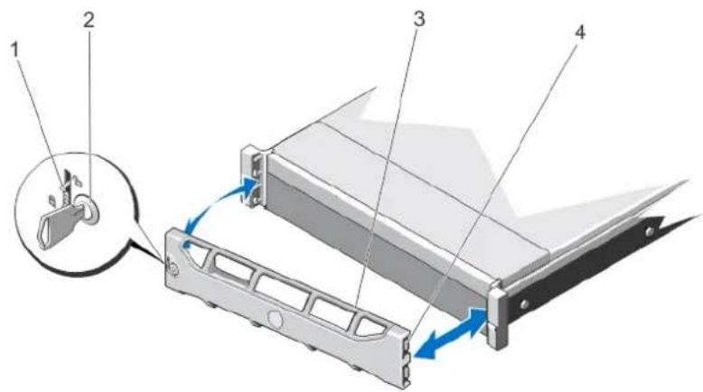
Removing The Front Bezel
1 Unlock the keylock at the left end of the bezel.
2 Lift the release latch next to the keylock.
3 Rotate the left end of the bezel away from the front panel.
4 Unhook the right end of the bezel and pull the bezel away from the system.
text_image
Diagram of a server rack with labeled components and directional arrows indicating movement or forceFigure 12. Removing and Installing the Front Bezel
1 release latch 2 keylock
3 front bezel 4 locking hook
Installing The Front Bezel
1 Hook the right end of the bezel onto the chassis.
2 Fit the free end of the bezel onto the system.
3 Secure the bezel with the keylock.
Opening And Closing The System
WARNING: Whenever you need to lift the system, get others to assist you. To avoid injury, do not attempt to lift the system by yourself.
WARNING: Opening or removing the system cover when the system is on may expose you to a risk of electric shock.
CAUTION: Many repairs may only be done by a certified service technician. You should only perform troubleshooting and simple repairs as authorized in your product documentation, or as directed by the online or telephone service and support team. Damage due to servicing that is not authorized by Dell is not covered by your warranty. Read and follow the safety instructions that came with the product.
CAUTION: Do not operate the system without the cover for a duration exceeding five minutes.
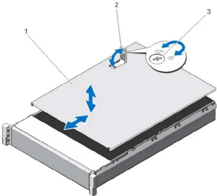
Opening The System

NOTE: It is recommended that you always use a static mat and static strap while working on components in the interior of the system.
1 Turn off the system and attached peripherals, and disconnect the system from the electrical outlet.
2 Rotate the latch release lock counter clockwise to the unlocked position.
3 Lift the latch on top of the system and slide the cover back.
4 Grasp the cover on both sides, and carefully lift the cover away from the system.
text_image
Diagram of a device with labeled components and directional arrows indicating motion or flow, showing layered structure and control panel.Figure 13. Opening and Closing the System
1 system cover 2 latch
3 latch release lock
Closing The System
1 Lift the latch on the cover.
2 Place the cover onto the chassis and offset the cover slightly back so that it clears the chassis hooks and lays flush on the chassis.
3 Push down the latch to move the cover into the closed position.
4 Rotate the latch release lock in a clockwise direction to secure the cover.
5 Reconnect the system to its electrical outlet and turn the system on, including any attached peripherals.
Inside The System

CAUTION: Many repairs may only be done by a certified service technician. You should only perform troubleshooting and simple repairs as authorized in your product documentation, or as directed by the online or telephone service and support team. Damage due to servicing that is not authorized by Dell is not covered by your warranty. Read and follow the safety instructions that came with the product.

NOTE: Components that are hot-swappable are marked orange and touch points on the components are marked blue.
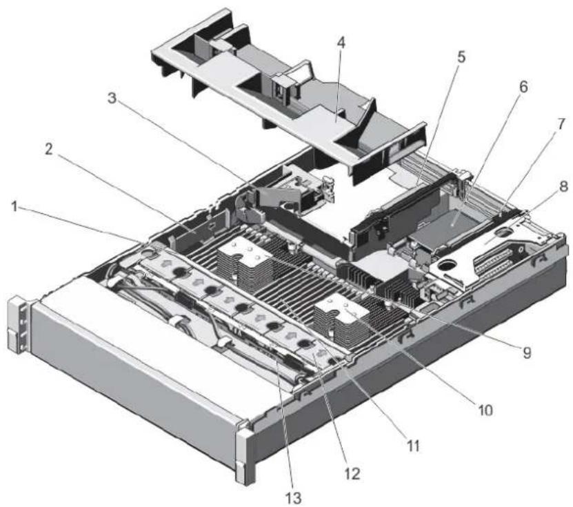
text_image
Exploded view diagram of a server rack with numbered components for identificationFigure 14. Inside the System—PowerEdge R720
1 cooling-fan assembly 2 cable securing bracket
3 PCIe card holder 4 cooling shroud
5 expansion-card riser 3 6 network daughter card
7 expansion-card riser 2 8 expansion-card riser 1
9 heat sink for processor 1 10 heat sink for processor 2
11 DIMMs (24) 12 cooling fans (6)
13 hard-drive backplane
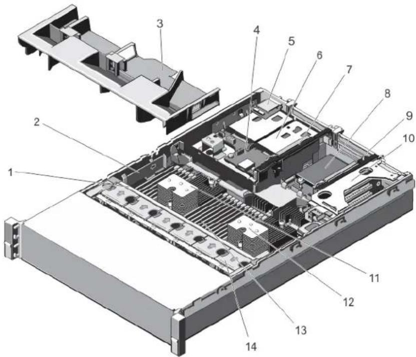
text_image
Exploded view diagram of a server rack with numbered components for identificationFigure 15. Inside the System—PowerEdge R720xd
1 cooling-fan assembly 2 cable securing bracket
3 cooling shroud 4 hard-drive backplane (back)
5 vFlash media slot 6 hard drives (back) (2)
7 expansion-card riser 3 8 network daughter card
9 expansion-card riser 2 10 expansion-card riser 1
11 heat sink for processor 1 12 heat sink for processor 2
13 DIMMs (24) 14 cooling fans (6)
Cooling Shroud
Removing The Cooling Shroud

CAUTION: Many repairs may only be done by a certified service technician. You should only perform troubleshooting and simple repairs as authorized in your product documentation, or as directed by the online or telephone service and support team. Damage due to servicing that is not authorized by Dell is not covered by your warranty. Read and follow the safety instructions that came with the product.

CAUTION: Never operate your system with the cooling shroud removed. The system may get overheated quickly, resulting in shutdown of the system and loss of data.
2 Open the system.
3 If installed, remove the full-length PCIe card.
4 Hold the touch points and lift the shroud away from the system.
1 Turn off the system, including any attached peripherals, and disconnect the system from the electrical outlet and peripherals.
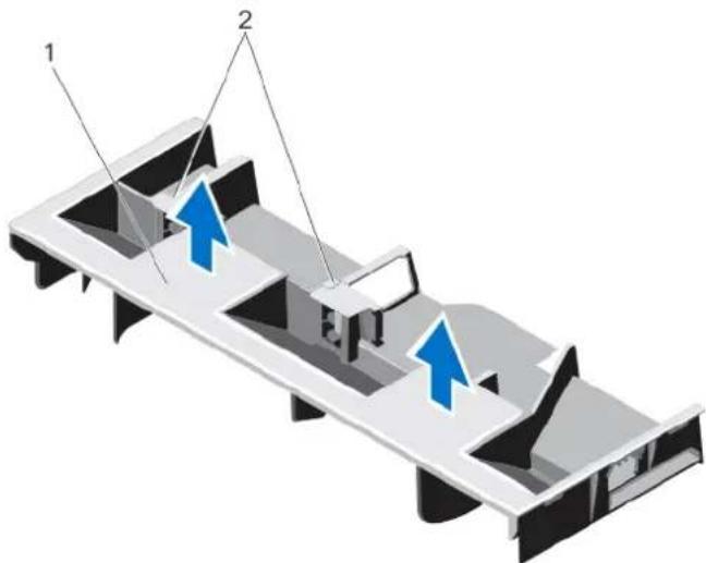
natural_image
Isometric architectural diagram of a building facade with two blue arrows indicating direction (no text or symbols)Figure 16. Removing and Installing the Cooling Shroud
1 cooling shroud 2 supports for a full-length PCIe card
Installing The Cooling Shroud

CAUTION: Many repairs may only be done by a certified service technician. You should only perform troubleshooting and simple repairs as authorized in your product documentation, or as directed by the online or telephone service and support team. Damage due to servicing that is not authorized by Dell is not covered by your warranty. Read and follow the safety instructions that came with the product.

NOTE: For proper seating of the cooling shroud in the chassis, ensure that the cables inside the system are routed along the chassis wall and secured using the cable securing bracket.
1 Align the tabs on the cooling shroud with the securing slots on the chassis.
2 Lower the cooling shroud into the chassis until it is firmly seated.
3 If applicable, replace the full-length PCIe card.
4 Close the system.
5 Reconnect the system to its electrical outlet and turn the system on, including any attached peripherals.
System memory
Your system supports DDR3 unbuffered ECC DIMMs (ECC UDIMMs), registered DIMMs (RDIMMs), and load reduced DIMMs (LRDIMMs). It supports DDR3 and DDR3L voltage specifications.

NOTE: MT/s indicates DIMM speed in MegaTransfers per second.
Memory bus operating frequency can be 1866 MT/s, 1600 MT/s, 1333 MT/s, 1066 MT/s, or 800 MT/s depending on:
• DIMM type (UDIMM, RDIMM, or LRDIMM)

NOTE: PowerEdge R720xd with 3.5 inch hard-drive configuration does not support LRDIMMs due to thermal limitations.
- DIMM configuration (number of ranks)
• maximum frequency of the DIMMs
• number of DIMMs populated per channel
• DIMM operating voltage
• system profile selected (for example, Performance Optimized, Custom, or Dense Configuration Optimized)
• maximum supported DIMM frequency of the processors
The system contains 24 memory sockets split into two sets of 12 sockets, one set per processor. Each 12-socket set is organized into four channels. In each channel, the release levers of the first socket are marked white, the second socket black, and the third socket green.

NOTE: DIMMs in sockets A1 to A12 are assigned to processor 1 and DIMMs in sockets B1 to B12 are assigned to processor 2.
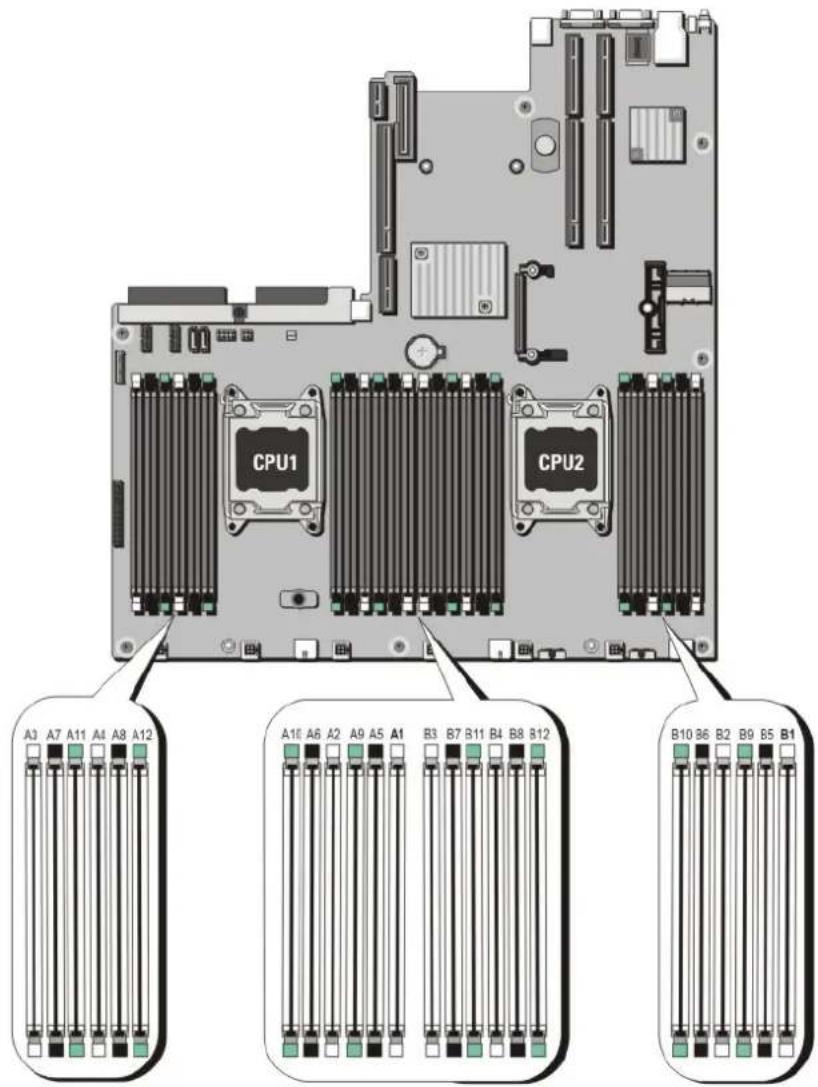
text_image
CPU1 CPU2 A3 A7 A11 A4 A8 A12 A16 A6 A2 A9 A5 A1 B3 B7 B11 B4 B8 B12 B10 B6 B2 B9 B5 B1Figure 17. Memory socket locations
Memory channels are organized as follows:
| Processor 1 | channel 0: slots A1, A5, and A9 |
| channel 1: slots A2, A6, and A10 | |
| channel 2: slots A3, A7, and A11 | |
| channel 3: slots A4, A8, and A12 |
| Processor 2 channel 0: slots B1, B5, and B9 |
| channel 1: slots B2, B6, and B10 |
The following table shows the memory populations and operating frequencies for the supported configurations.
DIMM Type DIMMs Populated/Channel
Operating Frequency (in MT/s) Maximum DIMM Rank/Channel
| 1.5 V 1.35 V | ||||
| UDIMM ECC 1 1600, 1333, 1066, and 800 1600, 1333, 1066 and 800 Dual rank | ||||
| 2 1600, 1333, 1066, and 800 1600, 1333, 1066 and 800 Dual rank | ||||
| RDIMM 1 1866, 1600, 1333, 1066, and 800 1600, 1333, 1066, and 800 Dual rank | ||||
| 800 | ||||
| 1333, 1066 and 800 1066 and 800 Quad rank | ||||
| 2 1866, 1600, 1333, 1066, and 800 1600, 1333, 1066, and 800 Dual rank | ||||
| 800 | ||||
| 1066 and 800 1066 and 800 Quad rank | ||||
| 3 1333, 1066 and 800 1066 and 800 Dual rank | ||||
| LRDIMM | 1 | 1866, 1600, 1333 and 1066 | 1600, 1333 and 1066 | Quad rank |
| 1600, 1333 and 1066 Not applicable | Octal rank | |||
| 2 1600, 1333 and 1066 | 1600, 1333 and 1066 | Quad rank | ||
| 1600, 1333 and 1066 Not applicable | Octal rank | |||
| 3 1333 and 1066 | 1066 | Quad rank | ||
| 1333 and 1066 | Not applicable | Octal rank | ||
General Memory Module Installation Guidelines
This system supports Flexible Memory Configuration, enabling the system to be configured and run in any valid chipset architectural configuration. The following are the recommended guidelines for best performance:
• UDIMMs, RDIMMs, and LRDIMMs must not be mixed.
- x4 and x8 DRAM based DIMMs can be mixed. For more information, see Mode-Specific Guidelines.
• A maximum of two UDIMMs can be populated in a channel.
- Up to two quad-rank RDIMMs and up to three dual- or single-rank RDIMMs can be populated per channel. When a quad-rank RDIMM is populated in the first slot with white release levers, the third DIMM slot in the channel with green release levers cannot be populated.
• Up to three LRDIMMs can be populated regardless of rank count.
- Populate DIMM sockets only if a processor is installed. For single-processor systems, sockets A1 to A12 are available. For dual-processor systems, sockets A1 to A12 and sockets B1 to B12 are available.
- Populate all sockets with white release tabs first, then black, and then green.
- Do not populate the third DIMM socket in a channel with green release tabs, if a quad-rank RDIMM is populated in the first socket with white release tabs.
- Populate the sockets by highest rank count in the following order — first in sockets with white release levers, then black, and then green. For example, if you want to mix quad-rank and dual-rank DIMMs, populate quad-rank DIMMs in the sockets with white release tabs and dual-rank DIMMs in the sockets with black release tabs.
- In a dual-processor configuration, the memory configuration for each processor should be identical. For example, if you populate socket A1 for processor 1, then populate socket B1 for processor 2, and so on.
• Memory modules of different sizes can be mixed provided that other memory population rules are followed (for example, 2 GB and 4 GB memory modules can be mixed).
- Populate four DIMMs per processor (one DIMM per channel) at a time to maximize performance.
- If memory modules with different speeds are installed, they will operate at the speed of the slowest installed memory module(s) or slower depending on system DIMM configuration.
Mode-Specific Guidelines
Four memory channels are allocated to each processor. The allowable configurations depend on the memory mode selected.

NOTE: x4 and x8 DRAM based DIMMs can be mixed, providing support for RAS features. However, all guidelines for specific RAS features must be followed. x4 DRAM based DIMMs retain Single Device Data Correction (SDDC) in memory optimized (independent channel) mode. x8 DRAM based DIMMs require Advanced ECC mode to gain SDDC.
The following sections provide additional slot population guidelines for each mode.
Advanced ECC (Lockstep)
Advanced ECC mode extends SDDC from x4 DRAM based DIMMs to both x4 and x8 DRAMs. This protects against single DRAM chip failures during normal operation.
Memory installation guidelines:
- Memory modules must be identical in size, speed, and technology.
- DIMMs installed in memory sockets with white release tabs must be identical and similar rule applies for sockets with black and green release tabs. This ensures that identical DIMMs are installed in matched pairs - for example, A1 with A2, A3 with A4, A5 with A6, and so on.

NOTE: Advanced ECC with Mirroring is not supported.
Memory Optimized (Independent Channel) Mode
This mode supports SDDC only for memory modules that use x4 device width and does not impose any specific slot population requirements.
Memory Sparing

NOTE: To use memory sparing, this feature must be enabled in the System Setup.
In this mode, one rank per channel is reserved as a spare. If persistent correctable errors are detected on a rank, the data from this rank is copied to the spare rank and the failed rank is disabled.
With memory sparing enabled, the system memory available to the operating system is reduced by one rank per channel. For example, in a dual-processor configuration with sixteen 4 GB dual-rank DIMMs, the available system memory is: 3/4 (ranks/channel) × 16 (DIMMs) × 4 GB = 48 GB, and not 16 (DIMMs) × 4 GB = 64 GB.

NOTE: Memory sparing does not offer protection against a multi-bit uncorrectable error.

NOTE: Both Advanced ECC/Lockstep and Optimizer modes support Memory Sparing.
Memory Mirroring
Memory Mirroring offers the strongest DIMM reliability mode compared to all other modes, providing improved uncorrectable multi-bit failure protection. In a mirrored configuration, the total available system memory is one half of the total installed physical memory. Half of
the installed memory is used to mirror the active DIMMs. In the event of an uncorrectable error, the system will switch over to the mirrored copy. This ensures SDDC and multi-bit protection.
Memory installation guidelines:
- Memory modules must be identical in size, speed, and technology.
- DIMMs installed in memory sockets with white release levers must be identical and similar rule applies for sockets with black and green release tabs. This ensures that identical DIMMs are installed in matched pairs - for example, A1 with A2, A3 with A4, A5 with A6, and so on.
Sample memory configurations
The following tables show sample memory configurations for one and two processor configurations that follow the appropriate memory guidelines stated in this section.
NOTE: 16 GB quad-rank RDIMMs are not supported.
NOTE: 1R, 2R and 4R in the following tables indicate single-, dual-, and quad-rank DIMMs respectively.
Table 1. Memory configurations—single processor
| System Capacity (in GB) | DIMM Size (in GB) | Number of DIMMs | DIMM Rank, Organization, and Frequency | DIMM Slot Population |
| 2 2 1 | 1R, x8, 1333 MT/s, | A1 | ||
| 1R, x8, 1600 MT/s | ||||
| 4 2 2 | 1R, x8, 1333 MT/s, | A1, A3 | ||
| 1R, x8, 1600 MT/s | ||||
| 8 2 4 | 1R, x8, 1333 MT/s, | A1, A2, A3, A4 | ||
| 1R, x8, 1600 MT/s | ||||
| 12 2 6 | 1R, x8, 1333 MT/s, | A1, A2, A3, A4, A5, A6 | ||
| 1R, x8, 1600 MT/s | ||||
| 16 2 8 | 1R, x8, 1333 MT/s A1, A2, A3, A4, A5, A6, A7, A8 | |||
| 4 | 4 | 2R, x8, 1333 MT/s, | A1, A2, A3, A4 | |
| 2R, x8, 1600 MT/s | ||||
| 24 2 12 | 1R, x8, 1333 MT/s A1, A2, A3, A4, A5, A6, A7, A8, A9, A10, A11, A12 | |||
| 4 | 6 | 2R, x8, 1333 MT/s, | A1, A2, A3, A4, A5, A6 | |
| 2R, x8, 1600 MT/s | ||||
| 48 4 12 | 2R, x8, 1333 MT/s A1, A2, A3, A4, A5, A6, A7, A8, A9, A10, A11, A12 | |||
| 8 | 6 | 2R, x4, 1333 MT/s, | A1, A2, A3, A4, A5, A6 | |
| 2R, x4, 1600 MT/s | ||||
| 96 8 12 | 2R, x4, 1333 MT/s A1, A2, A3, A4, A5, A6, A7, A8, A9, A10, A11, A12 | |||
| 16 | 6 | 2R, x4, 1333 MT/s, 2R, x4, 1600 MT/s | A1, A2, A3, A4, A5, A6 | |
| 128 16 8 | 2R, x4, 1333 MT/s, 2R, x4, 1600 MT/s, | A1, A2, A3, A4, A5, A6, A7, A8 | ||
| 144 16 and 8 10 | 2R, x4, 1333 MT/s A1, A2, A3, A4, A5, A6, A7, A8, A9, A11 | |||
| NOTE: 16 GB DIMMs must be installed in slots numbered A1, A2, A3, A4, A5, A6, A7, and A8 and 8 GB DIMMs must be installed in slots A9 and A11. | ||||
| 384 32 12 | LRDIMM, x4, 1333 MT/s A1, A2, A3, A4, A5, A6, A7, A8, A9, A10, A11, A12 | |||
| 768 64 12 | LRDIMM, x4, 1333 MT/s A1, A2, A3, A4, A5, A6, A7, A8, A9, A10, A11, A12 | |||
Table 2. Memory configurations—two processors
| System Capacity (in GB) | DIMM Size (in GB) Number of DIMMs DIMM Rank, Organization, and Frequency | DIMM Slot Population | ||
| 16 2 8 | 1R, x8, 1333 MT/s, | A1, A2, A3, A4 | ||
| 1R, x8, 1600 MT/s | B1, B2, B3, B4 | |||
| 32 | 2 16 | 1R, x8, 1333 MT/s | A1, A2, A3, A4, A5, A6, A7, A8 | |
| B1, B2, B3, B4, B5, B6, B7, B8 | ||||
| 32 | 4 8 | 2R, x8, 1333 MT/s, | A1, A2, A3, A4 | |
| 2R, x8, 1600 MT/s | B1, B2, B3, B4 | |||
| 64 | 4 16 | 2R, x8, 1333 MT/s | A1, A2, A3, A4, A5, A6, A7, A8 | |
| B1, B2, B3, B4, B5, B6, B7, B8 | ||||
| 8 | 8 | 2R, x4, 1333 MT/s, | A1, A2, A3, A4 | |
| 2R, x4, 1600 MT/s | B1, B2, B3, B4 | |||
| 96 | 4 24 | 2R, x8, 1333 MT/s | A1, A2, A3, A4, A5, A6, A7, A8, A9, A10, A11, A12 | |
| B1, B2, B3, B4, B5, B6, B7, B8, B9, B10, B11, B12 | ||||
| 8 | 12 | 2R, x4, 1333 MT/s, | A1, A2, A3, A4, A5, A6 | |
| 2R, x4, 1600 MT/s | B1, B2, B3, B4, B5, B6 | |||
| 128 8 16 | 2R, x4, 1333 MT/s A1, A2, A3, A4, A5, A6, A7, A8 | |||
| B1, B2, B3, B4, B5, B6, B7, B8 | ||||
| 16 | 8 | 2R, x4, 1333 MT/s, | A1, A2, A3, A4, B1, B2, B3, B4 | |
| 2R, x4, 1600 MT/s | ||||
| 160 8 20 | 2R, x4, 1333 MT/s A1, A2, A3, A4, A5, A6, A7, A8, A9, A11 | |||
| B1, B2, B3, B4, B5, B6, B7, B8, B9, B11 | ||||
| 16 and 8 12 | 2R, x4, 1333 MT/s, | A1, A2, A3, A4, A5, A6, | ||
| 2R, x4, 1600 MT/s | B1, B2, B3, B4, B5, B6 | |||
| NOTE: 16 GB DIMMs must be installed in slots numbered A1, A2, A3, A4, B1, B2, B3, and B4 and 8 GB DIMMs must be installed in slots A5, A6, B5, and B6. | ||||
| 192 8 24 | 2R, x4, 1333 MT/s A1, A2, A3, A4, A5, A6, A7, A8, A9, A10, A11, A12 | |||
| B1, B2, B3, B4, B5, B6, B7, B8, B9, B10, B11, B12 | ||||
| 16 12 | 2R, x4, 1333 MT/s, | A1, A2, A3, A4, A5, A6 | ||
| 2R, x4, 1600 MT/s | B1, B2, B3, B4, B5, B6 | |||
| 256 16 16 | 2R, x4, 1333 MT/s, | A1, A2, A3, A4, A5, A6, A7, A8 | ||
| 2R, x4, 1600 MT/s, | B1, B2, B3, B4, B5, B6, B7, B8 | |||
| 384 16 24 | 2R, x4, 1333 MT/s A1, A2, A3, A4, A5, A6, A7, A8, A9, A10, A11, A12 | |||
| B1, B2, B3, B4, B5, B6, B7, B8, B9, B10, B11. B12 | ||||
| 32 12 | 4R, x4, 1333 MT/s A1, A2, A3, A4, A5, A6 | |||
| B1, B2, B3, B4, B5, B6 | ||||
| 512 32 16 | 4R, x4, 1066 MT/s | A1, A2, A3, A4, A5, A6, A7, A8 | ||
| 4R, x4, 1333 MT/s | B1, B2, B3, B4, B5, B6, B7, B8 | |||
| 768 32 24 | LRDIMM, x4, 1333 MT/s A1, A2, A3, A4, A5, A6, A7, A8, A9, A10, A11, A12 | |||
System Capacity (in GB)
DIMM Size (in GB) Number of DIMMs DIMM Rank, Organization, and Frequency
DIMM Slot Population
| B1, B2, B3, B4, B5, B6, B7, B8, B9, B10, B11, B12 |
1536 64 24
LRDIMM, x4, 1333 MT/s A1, A2, A3, A4, A5, A6, A7, A8, A9, A10, A11, A12
B1, B2, B3, B4, B5, B6, B7, B8, B9, B10, B11, B12
Removing Memory Modules

WARNING: The memory modules are hot to the touch for some time after the system has been powered down. Allow time for the memory modules to cool before handling them. Handle the memory modules by the card edges and avoid touching the components or metallic contacts on the memory module.

CAUTION: Many repairs may only be done by a certified service technician. You should only perform troubleshooting and simple repairs as authorized in your product documentation, or as directed by the online or telephone service and support team. Damage due to servicing that is not authorized by Dell is not covered by your warranty. Read and follow the safety instructions that came with the product.

CAUTION: To ensure proper system cooling, memory-module blanks must be installed in any memory socket that is not occupied. Remove memory-module blanks only if you intend to install memory modules in those sockets.
1 Turn off the system, including any attached peripherals, and disconnect the system from the electrical outlet and peripherals.
2 Open the system.
3 Remove the cooling shroud.
4 Locate the appropriate memory-module socket(s).
5 To release the memory-module blank from the socket, simultaneously press the ejectors on both ends of the memory module socket.

CAUTION: Handle each memory module only by the card edges, making sure not to touch the middle of the memory module or metallic contacts. To avoid damaging the memory module, handle only one memory module at a time.
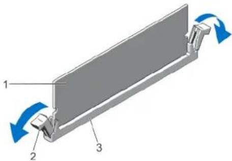
text_image
Diagram of a mechanical component with labeled parts and directional arrows indicating motion or forceFigure 18. Ejecting The Memory Module
1 memory module 2 memory-module socket ejectors (2)
3 memory-module socket
6 If a memory module or a memory-module blank is installed in the socket, remove it.

NOTE: Retain removed memory-module blank(s) for future use.
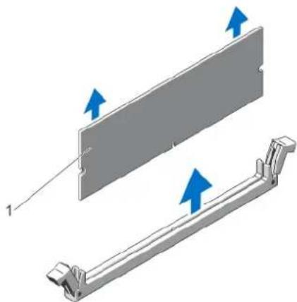
natural_image
Technical illustration of a mechanical assembly with two views, one showing a flat plate and the other a bracket (no text or symbols)Figure 19. Removing The Memory Module
1 memory module/memory-module blank
7 Install the cooling shroud.
8 Close the system.
9 Reconnect the system to its electrical outlet and turn the system on, including any attached peripherals.
Installing Memory Modules
WARNING: The memory modules are hot to the touch for some time after the system has been powered down. Allow time for the memory modules to cool before handling them. Handle the memory modules by the card edges and avoid touching the components or metallic contacts on the memory module.
CAUTION: Many repairs may only be done by a certified service technician. You should only perform troubleshooting and simple repairs as authorized in your product documentation, or as directed by the online or telephone service and support team. Damage due to servicing that is not authorized by Dell is not covered by your warranty. Read and follow the safety instructions that came with the product.
CAUTION: To ensure proper system cooling, memory-module blanks must be installed in any memory socket that is not occupied. Remove memory-module blanks only if you intend to install memory modules in those sockets.
1 Turn off the system, including any attached peripherals, and disconnect the system from the electrical outlet.
2 Open the system.
3 If applicable, remove the cooling shroud.
4 Locate the memory-module sockets.
CAUTION: Handle each memory module only by the card edges, making sure not to touch the middle of the memory module or metallic contacts. To avoid damaging the memory module, handle only one memory module at a time.
5 If a memory module or a memory-module blank is installed in the socket, remove it.
NOTE: Retain removed memory-module blank(s) for future use.
6 Align the memory-module's edge connector with the alignment key of the memory-module socket, and insert the memory module in the socket.
NOTE: The memory-module socket has an alignment key that allows you to install the memory module in the socket in only one orientation.
CAUTION: To prevent damage to the memory-module socket during installation, apply pressure at both ends of the memory module evenly. Do not apply pressure to the center of the memory module.
7 Press down on the memory module with your thumbs until the memory module snaps into place.
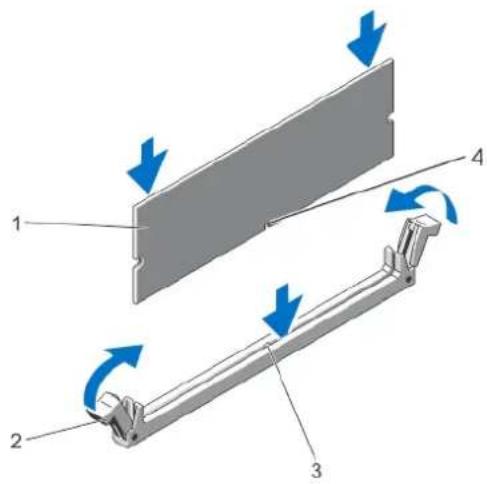
text_image
Diagram illustrating a mechanical assembly with labeled components and directional arrows indicating motion or force.Figure 20. Installing The Memory Module
1 memory module 2 memory-module ejectors
3 memory-module socket alignment key 4 memory-module alignment key
NOTE: When the memory module is properly seated in the socket, the levers on the memory-module socket align with the levers on the other identical sockets that have memory modules installed.
8 Repeat step 4 through step 7 of this procedure to install the remaining memory modules.
9 Replace the cooling shroud.
10 Close the system.
11 Reconnect the system to its electrical outlet and turn on the system, including any attached peripherals.
12 Press
The system should have already changed the value to reflect the newly installed memory.
13 If the value is incorrect, one or more of the memory modules may not be installed properly. Repeat step 4 through step 7 of this procedure, checking to ensure that the memory modules are firmly seated in their sockets.
14 Run the appropriate diagnostic test. For more information, see Using System Diagnostics.
Hard Drives
All hard drives connect to the system board through the hard-drive backplane. Hard drives are supplied in hot-swappable hard-drive carriers that fit in the hard-drive slots.
CAUTION: Before attempting to remove or install a hard drive while the system is running, see the documentation for the storage controller card to ensure that the host adapter is configured correctly to support hot-swap hard drive removal and insertion.
CAUTION: Do not turn off or reboot your system while the hard drive is being formatted. Doing so can cause a hard drive failure.
NOTE: Use only hard drives that have been tested and approved for use with the hard-drive backplane.
When you format a hard drive, allow enough time for the formatting to be completed. Be aware that high-capacity hard drives can take a number of hours to format.
Removing A 2.5 Inch Hard-Drive Blank

CAUTION: To maintain proper system cooling, all empty hard-drive slots must have hard-drive blanks installed.
1 If installed, remove the front bezel.
2 Press the release button and slide the hard-drive blank out until it is free of the hard-drive slot.
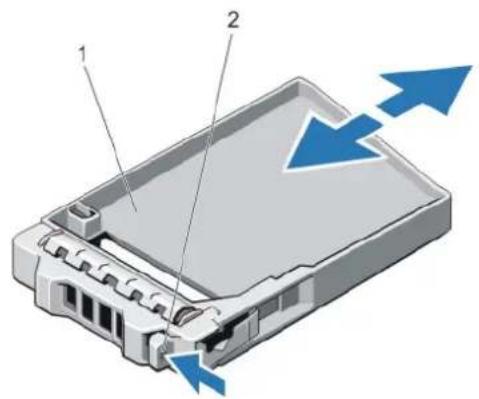
text_image
Diagram of a device showing two labeled components (1 and 2) with blue arrows indicating direction, likely illustrating a process or movement.Figure 21. Removing and Installing a 2.5 Inch Hard-Drive Blank
1 hard-drive blank 2 release button
Installing A 2.5 Inch Hard-Drive Blank
1 If installed, remove the front bezel.
2 Insert the hard-drive blank into the hard-drive slot until the release button clicks into place.
3 If applicable, install the front bezel.
Removing A 2.5 Inch Hard-Drive Blank (Back)

NOTE: This procedure applies only to PowerEdge R720xd.
CAUTION: To maintain proper system cooling, all empty hard-drive slots must have drive blanks installed.
Pull the hard-drive blank out until it is free of the hard-drive slot.
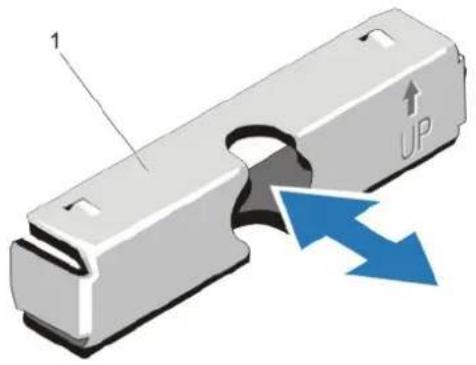
text_image
1 UPFigure 22. Removing and Installing a 2.5 Inch Hard-Drive Blank (Back)
1 hard-drive blank (back)
Installing A 2.5 Inch Hard-Drive Blank (Back)
NOTE: This procedure applies only to PowerEdge R720xd.
Insert the hard-drive blank into the hard-drive slot until it clicks into place.
Removing A 3.5 Inch Hard-Drive Blank
CAUTION: To maintain proper system cooling, all empty hard-drive slots must have drive blanks installed.
1 If installed, remove the front bezel.
2 Grasp the front of the hard-drive blank, press the release button and slide the blank out until it is free of the hard-drive slot.
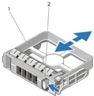
natural_image
3D diagram of a mechanical housing with labeled components and blue directional arrows indicating flow or movement (no text or symbols present)Figure 23. Removing and Installing a 3.5 Inch Hard-Drive Blank
1 hard-drive blank 2 release button
Installing A 3.5 Inch Hard-Drive Blank
1 If installed, remove the front bezel.
2 Insert the hard-drive blank into the hard-drive slot until the release button clicks into place.
3 If applicable, install the front bezel.
Removing A Hot-Swap Hard Drive

CAUTION: To prevent data loss, ensure that your operating system supports hot-swap drive installation. See the documentation supplied with your operating system.
1 From the management software, prepare the hard drive for removal. Wait until the indicators on the hard-drive carrier signal that the hard drive can be removed safely. For more information, see the documentation for the storage controller.
If the hard drive is online, the green activity/fault indicator flashes as the drive is turned off. When the hard-drive indicators are off, the hard drive is ready for removal.
2 Press the release button to open the hard-drive carrier release handle.
3 Slide the hard-drive carrier out until it is free of the hard-drive slot.

CAUTION: To maintain proper system cooling, all empty hard-drive slots must have hard-drive blanks installed.
4 Insert a hard-drive blank in the empty hard-drive slot.
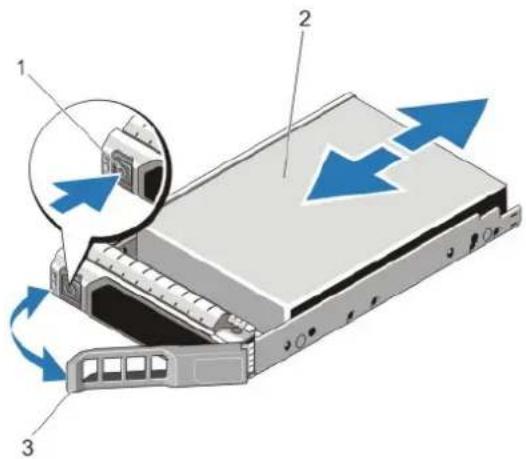
text_image
Diagram of a server rack with labeled components and directional arrows indicating movement or flowFigure 24. Removing and Installing a Hot-Swap Hard Drive
1 release button 2 hard drive
3 hard-drive carrier handle
Installing A Hot-Swap Hard Drive

CAUTION: Many repairs may only be done by a certified service technician. You should only perform troubleshooting and simple repairs as authorized in your product documentation, or as directed by the online or telephone service and support team. Damage due to servicing that is not authorized by Dell is not covered by your warranty. Read and follow the safety instructions that came with the product.

CAUTION: Use only hard drives that have been tested and approved for use with the hard-drive backplane.
△| CAUTION: Combining SAS and SATA hard drives in the same RAID volume is not supported.
CAUTION: When installing a hard drive, ensure that the adjacent drives are fully installed. Inserting a hard-drive carrier and attempting to lock its handle next to a partially installed carrier can damage the partially installed carrier's shield spring and make it unusable.
CAUTION: To prevent data loss, ensure that your operating system supports hot-swap drive installation. See the documentation supplied with your operating system.
CAUTION: When a replacement hot-swappable hard drive is installed and the system is powered on, the hard drive automatically begins to rebuild. Make absolutely sure that the replacement hard drive is blank or contains data that you wish to have overwritten. Any data on the replacement hard drive is immediately lost after the hard drive is installed.
1 If a hard-drive blank is installed in the hard-drive slot, remove it.
2 Install a hard drive in the hard-drive carrier.
3 Press the release button on the front of the hard-drive carrier and open the hard-drive carrier handle.
4 Insert the hard-drive carrier into the hard-drive slot until the carrier connects with the backplane.
5 Close the hard-drive carrier handle to lock the hard drive in place.
Removing A Hard Drive From A Hard-Drive Carrier
1 Remove the screws from the slide rails on the hard-drive carrier.
2 Lift the hard drive out of the hard-drive carrier.
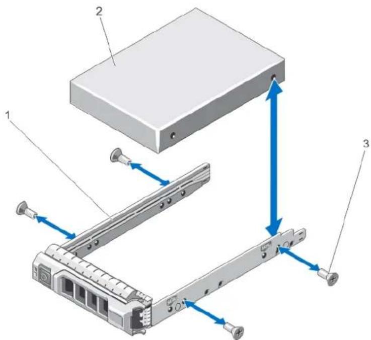
text_image
Diagram of a server rack with labeled components and directional arrows indicating assembly or movement.Figure 25. Removing and Installing a Hard Drive Into a Hard-Drive Carrier
1 hard-drive carrier 2 hard drive
3 screws (4)
Installing A Hard Drive Into A Hard-Drive Carrier

CAUTION: Many repairs may only be done by a certified service technician. You should only perform troubleshooting and simple repairs as authorized in your product documentation, or as directed by the online or telephone service and support team. Damage due to servicing that is not authorized by Dell is not covered by your warranty. Read and follow the safety instructions that came with the product.
1 Insert the hard drive into the hard-drive carrier with the connector end of the hard drive toward the back.
2 Align the screw holes on the hard drive with the set of screw holes on the hard-drive carrier.
When aligned correctly, the back of the hard drive is flush with the back of the hard-drive carrier.
3 Attach the screws to secure the hard drive to the hard-drive carrier.
Optical Drive (Optional)
Removing The Optical Drive

NOTE: This procedure applies only to PowerEdge R720.

CAUTION: Many repairs may only be done by a certified service technician. You should only perform troubleshooting and simple repairs as authorized in your product documentation, or as directed by the online or telephone service and support team. Damage due to servicing that is not authorized by Dell is not covered by your warranty. Read and follow the safety instructions that came with the product.
1 If installed, remove the front bezel.
2 Turn off the system, including any attached peripherals, and disconnect the system from the electrical outlet and peripherals.
3 Open the system.
4 Remove the cooling-fan assembly.
5 Disconnect the power/data cable from the back of the optical drive.
Note the routing of the power/data cable on the side of the system as you remove them from the system board and the optical drive. You must route these cables properly when you replace them to prevent them from being pinched or crimped.
6 To release the optical drive, press and push the release tab toward the front of the system.
7 Slide the optical drive out of the system until it is free of the optical-drive slot.
8 If you are not adding a new optical drive, install the optical-drive blank.
9 Install the cooling-fan assembly.
10 Close the system.
11 Reconnect the system to its electrical outlet and turn the system on, including any attached peripherals.
12 If applicable, install the front bezel.
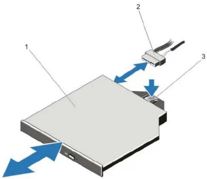
text_image
Diagram showing a device with labeled components and directional arrows indicating data flow or movement.Figure 26. Removing and Installing the Optical Drive
1 optical drive 2 power/data cable 3 release tab
Installing The Optical Drive

NOTE: This procedure applies only to PowerEdge R720.

CAUTION: Many repairs may only be done by a certified service technician. You should only perform troubleshooting and simple repairs as authorized in your product documentation, or as directed by the online or telephone service and support team. Damage due to servicing that is not authorized by Dell is not covered by your warranty. Read and follow the safety instructions that came with the product.
1 If installed, remove the front bezel.
2 Turn off the system, including any attached peripherals, and disconnect the system from its electrical outlet.
3 Open the system.
4 To remove the optical drive blank, press the blue release tab at the back of the blank and push the blank out of the system.
5 Align the optical drive with the optical drive slot on the front of chassis.
6 Slide the optical drive into the slot until the latch snaps into place.
7 Connect the power/data cable to the back of the drive.
8 Route the power/data cable along the inside left wall of the chassis.
9 Connect the power/data cable to the connectors on the system board.
10 Install the cooling-fan assembly.
11 Close the system.
12 If applicable, install the front bezel.
13 Reconnect the system to its electrical outlet and turn the system on, including any attached peripherals.
Cooling Fans
Your system supports hot-swappable cooling fans.
NOTE: In the event of a problem with a particular fan, the fan number is referenced by the system's management software, allowing you to easily identify and replace the proper fan by noting the fan numbers on the cooling fan assembly.
Removing A Cooling Fan
WARNING: Opening or removing the system cover when the system is on may expose you to a risk of electric shock. Exercise utmost care while removing or installing cooling fans.
CAUTION: Many repairs may only be done by a certified service technician. You should only perform troubleshooting and simple repairs as authorized in your product documentation, or as directed by the online or telephone service and support team. Damage due to servicing that is not authorized by Dell is not covered by your warranty. Read and follow the safety instructions that came with the product.
△| CAUTION: The cooling fans are hot-swappable. To maintain proper cooling while the system is on, replace only one fan at a time.
△| CAUTION: Do not operate the system with the cover removed for a duration exceeding five minutes.
NOTE: The procedure for removing each fan is identical.
1 Open the system.
2 Press the fan release tab and lift the cooling fan out of the cooling-fan assembly.
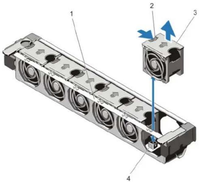
text_image
Technical diagram of a mechanical component with numbered parts and directional arrows indicating motion or assembly.Figure 27. Removing and Installing a Cooling Fan
1 cooling-fan assembly 2 fan release tab
3 cooling fans (6) 4 cooling-fan connectors (6)
Installing A Cooling Fan
CAUTION: The PowerEdge R720 and R720xd cooling fans are not compatible with each other and must not be interchanged.
CAUTION: Many repairs may only be done by a certified service technician. You should only perform troubleshooting and simple repairs as authorized in your product documentation, or as directed by the online or telephone service and support team. Damage due to servicing that is not authorized by Dell is not covered by your warranty. Read and follow the safety instructions that came with the product.
1 Open the system.
2 Align the plug at the base of the cooling fan with the connector on the system board.
3 Slide the cooling fan into the securing slots until the tabs lock into place.
4 Close the system.
Removing The Cooling-Fan Assembly
CAUTION: Many repairs may only be done by a certified service technician. You should only perform troubleshooting and simple repairs as authorized in your product documentation, or as directed by the online or telephone service and support team. Damage due to servicing that is not authorized by Dell is not covered by your warranty. Read and follow the safety instructions that came with the product.
1 Turn off the system, including any attached peripherals, and disconnect the system from the electrical outlet and peripherals.
2 Open the system.
3 Unlock the cooling-fan assembly from the chassis by rotating the blue release lever upward.
4 Lift the cooling-fan assembly out of the chassis.
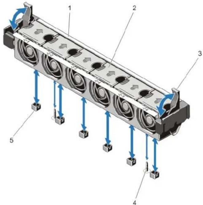
text_image
Technical diagram of a mechanical component with numbered parts and blue directional arrows indicating flow or movement.Figure 28. Removing and Installing the Cooling-Fan Assembly
1 cooling-fan assembly 2 cooling fans (6)
3 blue release levers (2) 4 guide pins (2)
5 cooling-fan connectors (6)
Installing The Cooling-Fan Assembly
CAUTION: Many repairs may only be done by a certified service technician. You should only perform troubleshooting and simple repairs as authorized in your product documentation, or as directed by the online or telephone service and support team. Damage due to servicing that is not authorized by Dell is not covered by your warranty. Read and follow the safety instructions that came with the product.
CAUTION: Ensure that the cables are correctly installed and retained by the cable retention bracket before installing the cooling fan assembly. Incorrectly installed cables may get damaged.
1 Align the cooling-fan assembly slots with the guide pins on the chassis.
2 Slide the cooling-fan assembly into the chassis.
3 Lock the cooling-fan assembly into the chassis by rotating the blue release levers downward until firmly seated.
4 Close the system.
5 Reconnect the system to its electrical outlet and turn the system on, including any attached peripherals.
Internal USB Memory Key (Optional)
An optional USB memory key installed inside your system can be used as a boot device, security key, or mass storage device. The USB connector must be enabled by the Internal USB Port option in the Integrated Devices screen of the System Setup.
To boot from the USB memory key, configure the USB memory key with a boot image and then specify the USB memory key in the boot sequence in the System Setup.
NOTE To locate the internal USB connector (J_USB_INT) on the system board, see System Board Connectors.
Replacing The Internal USB Key
CAUTION: Many repairs may only be done by a certified service technician. You should only perform troubleshooting and simple repairs as authorized in your product documentation, or as directed by the online or telephone service and support team. Damage due to servicing that is not authorized by Dell is not covered by your warranty. Read and follow the safety instructions that came with the product.
1 Turn off the system, including any attached peripherals, and disconnect the system from the electrical outlet and peripherals.
2 Open the system.
3 Locate the USB connector / USB key on the system board.
To locate the USB connector (J_USB_INT), see System Board Connectors.
4 If installed, remove the USB key.
5 Insert the USB key into the USB connector.
6 Close the system.
7 Reconnect the system to its electrical outlet and turn the system on, including any attached peripherals.
8 Enter the System Setup and verify that the USB key is detected by the system.
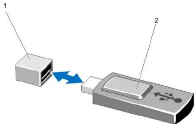
text_image
Diagram showing two connected devices with labeled parts and directional arrows indicating data flow or connection.Figure 29. Replacing the Internal USB Key
1 USB memory key connector 2 USB memory key
PCIe Card Holder
Removing The PCIe Card Holder
CAUTION: Many repairs may only be done by a certified service technician. You should only perform troubleshooting and simple repairs as authorized in your product documentation, or as directed by the online or telephone service and support team. Damage due to servicing that is not authorized by Dell is not covered by your warranty. Read and follow the safety instructions that came with the product.
CAUTION: Do not use your system without the PCIe card holder installed. The PCIe card holder is necessary to ensure proper system cooling.
1 Turn off the system, including any attached peripherals, and disconnect the system from the electrical outlet and peripherals.
2 Open the system.
3 If installed, remove the full-length PCIe card.
4 Press the release tab and the touch-point to release the PCIe card holder from the chassis.
5 Lift the PCIe card holder out of the chassis.
NOTE: To ensure proper system cooling, you must replace the PCIe card holder.

text_image
Technical diagram showing mechanical assembly with labeled components and directional arrows indicating movement or forceFigure 30. Removing and Installing the PCIe Card Holder
1 PCIe card holder 2 release tab
Installing The PCIe Card Holder

CAUTION: Many repairs may only be done by a certified service technician. You should only perform troubleshooting and simple repairs as authorized in your product documentation, or as directed by the online or telephone service and support team. Damage due to servicing that is not authorized by Dell is not covered by your warranty. Read and follow the safety instructions that came with the product.

CAUTION: Do not use your system without the PCIe card holder installed. The PCIe card holder is necessary to ensure proper system cooling.
1 Turn off the system, including any attached peripherals, and disconnect the system from its electrical outlet.
2 Open the system.
3 Align the PCIe card holder with the projection on the chassis and push it down until firmly seated.
4 If applicable, replace the full-length PCIe card.
5 Close the system.
6 Reconnect the system to its electrical outlet and turn the system on, including any attached peripherals.
Opening And Closing The PCIe Card Holder Latch

CAUTION: Many repairs may only be done by a certified service technician. You should only perform troubleshooting and simple repairs as authorized in your product documentation, or as directed by the online or telephone service and support team. Damage due to servicing that is not authorized by Dell is not covered by your warranty. Read and follow the safety instructions that came with the product.
1 Turn off the system, including any attached peripherals, and disconnect the system from the electrical outlet and peripherals.
2 Open the system.
3 To open the PCIe card holder latch, press the tab.
4 To close the PCIe card holder latch, rotate the latch clockwise until it locks.

NOTE: Before installing a full-length PCIe card, the PCIe card holder latch must be closed. When the full-length PCIe card is installed, open the PCIe card holder latch. Before removing the full-length PCIe card, you must close the PCIe card holder latch.
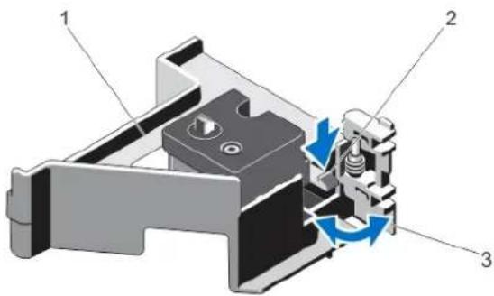
text_image
Technical diagram of a mechanical assembly with labeled components and directional arrows indicating motion or flow.Figure 31. Opening and Closing the PCIe Card Holder Latch
1 PCIe card holder 2 tab
3 PCIe card holder latch
5 Close the system.
6 Reconnect the system to its electrical outlet and turn the system on, including any attached peripherals.
Top Cover Lock Latch
Installing The Top Cover Lock Latch

CAUTION: Many repairs may only be done by a certified service technician. You should only perform troubleshooting and simple repairs as authorized in your product documentation, or as directed by the online or telephone service and support team. Damage due to servicing that is not authorized by Dell is not covered by your warranty. Read and follow the safety instructions that came with the product.
1 Turn off the system, including any attached peripherals, and disconnect the system from its electrical outlet.
2 Open the system.
3 Remove the cover.
4 If applicable, remove the PCIe card holder.
5 Orient the top cover lock latch in a direction such that the screw hole on the top cover lock latch is aligned with the screw hole on the latch.
6 Slide the top cover lock latch until the screw holes are completely aligned.
7 Attach the top cover lock latch to the latch using the Torx screw.
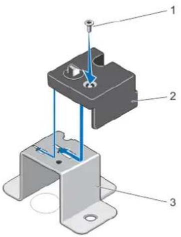
text_image
Technical diagram of a mechanical assembly with labeled parts 1, 2, and 3Figure 32. Installing the Top Cover Lock Latch
1 screw 2 top cover lock latch
3 latch
8 If applicable, install the PCIe card holder.
9 Close the system.
10 Reconnect the system to its electrical outlet and turn the system on, including any attached peripherals.
Cable Retention Bracket
Removing The Cable Retention Bracket

CAUTION: Many repairs may only be done by a certified service technician. You should only perform troubleshooting and simple repairs as authorized in your product documentation, or as directed by the online or telephone service and support team. Damage due to servicing that is not authorized by Dell is not covered by your warranty. Read and follow the safety instructions that came with the product.
1 Turn off the system, including any attached peripherals, and disconnect the system from the electrical outlet and peripherals.
2 Open the system.
3 Remove the cooling shroud.
4 Remove all cables routed through the cable retention bracket.
5 Press the tab and slide the cable retention bracket toward the front of the chassis to release it from the chassis.
6 Lift the cable retention bracket out of the chassis.
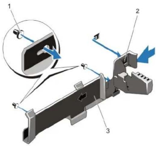
text_image
Technical diagram of a mechanical assembly with labeled parts and directional arrows indicating motion or forceFigure 33. Removing and Installing the Cable Retention Bracket
1 alignment pins (2) 2 tab
3 cable retention bracket
Installing The Cable Retention Bracket

CAUTION: Many repairs may only be done by a certified service technician. You should only perform troubleshooting and simple repairs as authorized in your product documentation, or as directed by the online or telephone service and support team. Damage due to servicing that is not authorized by Dell is not covered by your warranty. Read and follow the safety instructions that came with the product.
1 Turn off the system, including any attached peripherals, and disconnect the system from its electrical outlet.
2 Open the system.
3 Using alignment pins as guide, slide the cable retention bracket along the chassis wall until the tab snaps into place.
4 Place all cables to be routed in the cable retention bracket.
5 Install the cooling shroud.
6 Close the system.
7 Reconnect the system to its electrical outlet and turn the system on, including any attached peripherals.
Expansion Cards And Expansion-Card Risers

NOTE: A missing or an unsupported expansion-card riser logs an SEL event. It does not prevent your system from powering on and no BIOS POST message or F1/F2 pause is displayed.
Expansion Card Installation Guidelines
Depending on your system configuration:
• PowerEdge R720 supports seven expansion cards
• PowerEdge R720xd supports six expansion cards
The following PCI Express Generation 3 expansion cards are supported:
Table 3. Supported Expansion Cards
Riser PCIe Slot Processor Connection Height Length Link Width Slot Width
| 1 1 Processor 2 Low ProfileHalf Length x8 x16 | |||||||
| 1 2 Processor 2 Low ProfileHalf Length x8 x16 | |||||||
| 1 3 Processor 2 Low ProfileHalf Length x8 x16 | |||||||
| 2 4 Processor 2 Standard Height Full Length | x16 | x16 | |||||
| 2 | 5 | Processor 1 | Standard Height | Full Length | x8 | x16 | |
| 3 (default) | 6 | Processor 1 | Standard Height | Full Length | x8 | x16 | |
| 3 (default) | 7 | Processor 1 | Standard Height | Full Length | x8 | x16 | |
| 3 (alternate) | 6 | Processor 1 | Standard Height | Full Length | x16 | x16 | |
NOTE: To use PCIe slots 1 through 4 on the riser, both the processors must be installed.
NOTE: PowerEdge R720xd does not support riser 3 (default).
NOTE: The expansion-card slots are not hot-swappable.
The following table provides guidelines for installing expansion cards to ensure proper cooling and mechanical fit. The expansion cards with the highest priority should be installed first using the slot priority indicated. All other expansion cards should be installed in card priority and slot priority order.
Table 4. Expansion Card Installation Order
| Card Priority | Card Type | Slot Priority—PowerEdge R720 | Slot Priority—PowerEdge R720xd | Max Allowed | |||
| 2-Processor | 1-Processor | 2-Processor | 1-Processor | R720 | R720xd | ||
| 1 | Dell PowerEdge Express Flash (PCIe SSD) Bridge | 4 | Not Supported | Not Supported | Not Supported | 1 | 0 |
| 2 | GPU (double wide) | 6, 4 | Not Supported | Not Supported | Not Supported | 2 | 0 |
| GPU (single wide) | 4, 6, 7, 5 | Not Supported | Not Supported | Not Supported | 4 | 0 | |
| 3 | GPU Host Interface Card (HIC) | 4, 6 | 6 | Not Supported | Not Supported | 2 | 0 |
| 4 | RAID H810 | 7, 6, 4, 5 | 7, 6, 5 | 6, 4, 5 | 6, 5 | 4 | 3 |
| RAID H710P | 2 | Not Supported | Not Supported | Not Supported | 1 | 0 | |
| 5 | FC16 HBA Full Height,FH | 5, 7, 4, 6 | 5, 7, 6 | 4, 6, 5 | 6, 5 | 4 | 3 |
| Low Profile,LP | 2, 3, 1 | Not Supported | 2, 3, 1 | Not Supported | 3 | 3 | |
| 6 | Converged Network Adapters (CNAs)Full Height,FH | 5, 7, 4, 6 | 5, 7, 6 | 4, 6, 5 | 6, 5 | 4 | 3 |
| NOTE: Brocade 1020 CNA adapter must not be installed in Slot 1. | |||||||
| Low Profile,LP | 2, 3, 1 | Not Supported | 2, 3, 1 | Not Supported | 2-3 | 2-3 | |
Card Card Type Slot Priority—PowerEdge R720 Slot Priority—PowerEdge R720xd Max Allowed
| Priority | 2-Processor 1-Processor 2-Processor 1-Processor R720 R720xd | ||||||
| 7 10 Gb NICsFull Height,FH | 5, 7, 4, 6 5, 7, 6 4, 6, 5 6, 5 4 3 | ||||||
| Low Profile,LP | 2, 3, 1 | Not Supported | 2, 3, 1 | Not Supported | 3 | 3 | |
| 8 | FC8/4 HBA | 5, 7, 4, 6 | 5, 7, 6 | 4, 6, 5 | 6, 5 | 4 | 3 |
| NOTE: Brocade FC8 low profile HBA must not be installed in Slot 1. | |||||||
| Low Profile,LP | 2, 3, 1 | Not Supported | 2, 3, 1 | Not Supported | 2-3 | 2-3 | |
| 9 | 1 Gb NICs | 5, 7, 4, 6 5, 7, 6 4, 6, 5 6, 5 4 3 | |||||
| Low Profile,LP | 2, 3, 1 | Not Supported | 2, 3, 1 | Not Supported | 3 | 3 | |
| 10 | Non-RAID | 5, 7, 4, 6 | 5, 7, 6 | 4, 6, 5 | 6, 5 | 4 | 3 |
| Low Profile,LP | 2, 3, 1 | Not Supported | 2, 3, 1 | Not Supported | 3 | 3 | |
| 11 | Dell ioDrive | 5, 7, 4, 6 5, 7, 6 4, 6, 5 6, 5 4 3 | |||||
Removing An Expansion Card From The Expansion-Card Riser 2 Or 3

CAUTION: Many repairs may only be done by a certified service technician. You should only perform troubleshooting and simple repairs as authorized in your product documentation, or as directed by the online or telephone service and support team. Damage due to servicing that is not authorized by Dell is not covered by your warranty. Read and follow the safety instructions that came with the product.
1 Turn off the system, including any attached peripherals, and disconnect the system from the electrical outlet and peripherals.
2 Open the system.
3 Disconnect any cables connected to the expansion card.
4 Lift the expansion-card latch out of the slot.
5 Grasp the expansion card by its edges, and remove it from the expansion-card connector.
6 If you are removing the card permanently, install a metal filler bracket over the empty expansion slot opening and close the expansion-card latch.

NOTE: You must install a filler bracket over an empty expansion slot to maintain Federal Communications Commission (FCC) certification of the system. The brackets also keep dust and dirt out of the system and aid in proper cooling and airflow inside the system.
7 Close the system.
8 Reconnect the system to its electrical outlet and turn the system on, including any attached peripherals.
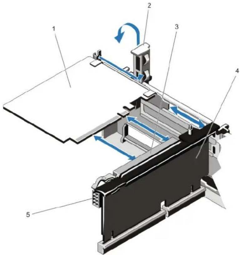
text_image
Technical diagram of a mechanical device with numbered components and directional arrows indicating motion or flow.Figure 34. Removing and Installing the Expansion Card
1 expansion card 2 expansion-card latch
3 expansion-card connector 4 expansion-card riser
5 power connector (for GPU cards)
Installing An Expansion Card Into The Expansion-Card Riser 2 Or 3

CAUTION: Many repairs may only be done by a certified service technician. You should only perform troubleshooting and simple repairs as authorized in your product documentation, or as directed by the online or telephone service and support team. Damage due to servicing that is not authorized by Dell is not covered by your warranty. Read and follow the safety instructions that came with the product.
1 Unpack the expansion card and prepare it for installation.
For instructions, see the documentation accompanying the card.
2 Turn off the system, including any attached peripherals, and disconnect the system from the electrical outlet and peripherals.
3 Open the system.
4 Lift the expansion-card latch and remove the filler bracket.
5 Holding the card by its edges, position the card so that the connector on the expansion card aligns with the expansion-card connector on the riser.
6 Insert the card-edge connector firmly into the expansion-card connector until the card is fully seated.
7 Replace the expansion-card latch.
8 To install a full-length card, use the supports provided on the cooling shroud.
9 If applicable, connect cables to the expansion card.
NOTE: When installing a GPU card on riser 2 or riser 3 (default), connect the GPU card power cable to the power connector on the riser.
10 Close the system.
11 Reconnect the system to its electrical outlet and turn the system on, including any attached peripherals.
12 Install any device drivers required for the card as described in the documentation for the card.
Removing An Expansion Card From The Expansion-Card Riser 1
CAUTION: Many repairs may only be done by a certified service technician. You should only perform troubleshooting and simple repairs as authorized in your product documentation, or as directed by the online or telephone service and support team. Damage due to servicing that is not authorized by Dell is not covered by your warranty. Read and follow the safety instructions that came with the product.
NOTE: The expansion-card riser 1 can be used only when both the processors are installed.
1 Turn off the system, including any attached peripherals, and disconnect the system from the electrical outlet and peripherals.
2 Open the system.
3 Disconnect any cables connected to the expansion card.
4 Remove the expansion-card riser.
5 Press tab A and rotate the latch clockwise.
6 Press tab B and rotate the latch down.
7 Remove the expansion card from the expansion-card riser.
8 If you are removing the card permanently, install a metal filler bracket over the empty expansion slot opening and close the expansion-card latch.
NOTE: You must install a filler bracket over an empty expansion slot to maintain Federal Communications Commission (FCC) certification of the system. The brackets also keep dust and dirt out of the system and aid in proper cooling and airflow inside the system.
9 Reinstall the expansion-card riser.
10 Close the system.
11 Reconnect the system to its electrical outlet and turn the system on, including any attached peripherals.
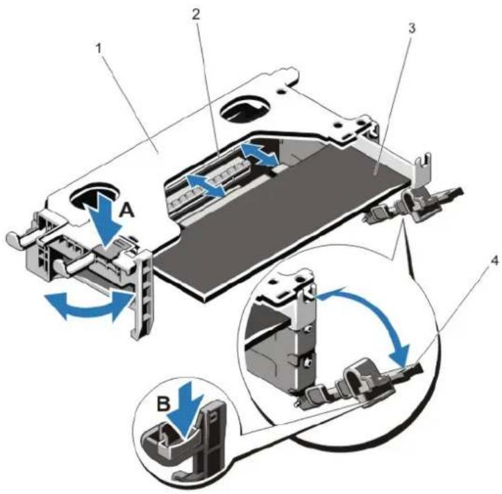
text_image
1 2 3 A 4 BFigure 35. Removing and Installing the Expansion-Card Riser 1
1 expansion-card riser 1 cage 2 expansion-card connector
3 expansion card 4 expansion-card latches (2)
Installing An Expansion Card Into The Expansion-Card Riser 1

CAUTION: Many repairs may only be done by a certified service technician. You should only perform troubleshooting and simple repairs as authorized in your product documentation, or as directed by the online or telephone service and support team. Damage due to servicing that is not authorized by Dell is not covered by your warranty. Read and follow the safety instructions that came with the product.

NOTE: The expansion-card riser 1 can be used only when both the processors are installed.
1 Unpack the expansion card and prepare it for installation.
For instructions, see the documentation accompanying the card.
2 Turn off the system, including any attached peripherals, and disconnect the system from the electrical outlet and peripherals.
3 Open the system.
4 Remove the expansion-card riser.
5 Press tab A and rotate the latch clockwise.
6 Press tab B and rotate the latch down.
7 Holding the card by its edges, position the card so that the card-edge connector aligns with the expansion-card connector.
8 Insert the card-edge connector firmly into the expansion-card connector until the card is fully seated.
9 Close the expansion-card latches.
10 If applicable, connect any cables to the expansion card.
11 Install the expansion-card riser.
12 Close the system.
13 Reconnect the system to its electrical outlet and turn the system on, including any attached peripherals.
Removing Expansion-Card Risers

CAUTION: Many repairs may only be done by a certified service technician. You should only perform troubleshooting and simple repairs as authorized in your product documentation, or as directed by the online or telephone service and support team. Damage due to servicing that is not authorized by Dell is not covered by your warranty. Read and follow the safety instructions that came with the product.

NOTE: The expansion-card riser 1 can be used only when both the processors are installed.
1 Turn off the system, including any attached peripherals, and disconnect the system from the electrical outlet and peripherals.
2 Open the system.
3 Holding the touch points, lift the expansion-card riser from the riser connector on the system board.
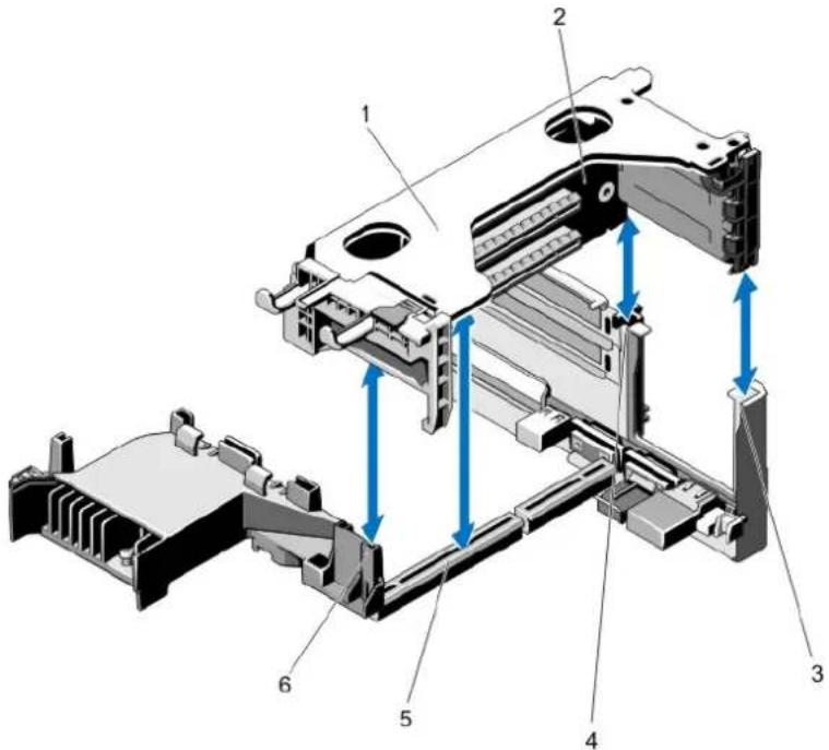
text_image
Technical diagram of a device's internal structure with numbered components and blue directional arrows indicating movement or flow.Figure 36. Removing and Installing the Expansion Card Riser 1
1 expansion-card riser 1 cage 2 expansion-card riser 1
3 riser guide-back (right) 4 riser guide-back (left)
5 expansion-card riser 1 connector 6 riser guide-front
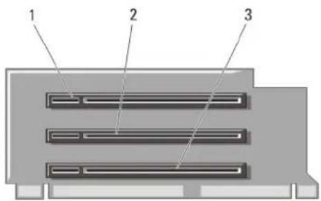
text_image
1 2 3Figure 37. Identifying Connectors on the Expansion Card Riser 1
1 expansion-card slot 1 2 expansion-card slot 2
3 expansion-card slot 3
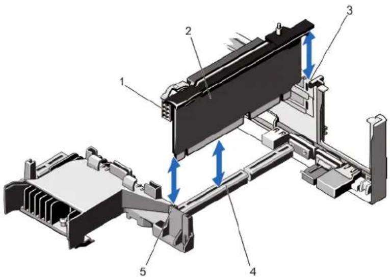
text_image
Technical diagram of a mechanical assembly with numbered components and directional arrows indicating motion or movement.Figure 38. Removing and Installing the Expansion Card Riser 2
1 power connector (for GPU cards) 2 expansion-card riser 2
3 riser guide-back 4 expansion-card riser 2 connector
5 riser guide-front
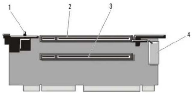
text_image
Technical diagram of a mechanical or electronic component with numbered parts labeled 1 to 4Figure 39. Identifying Connectors on the Expansion Card Riser 2
1 chassis intrusion switch 2 expansion-card slot 4
3 expansion-card slot 5 4 power connector (for GPU cards)
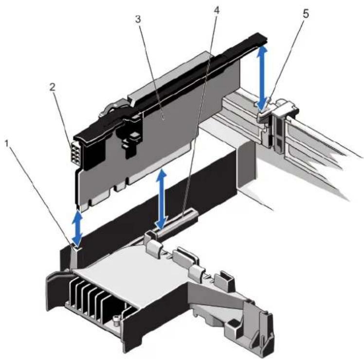
text_image
Technical diagram of a mechanical assembly with numbered components and directional arrows indicating assembly steps.Figure 40. Removing and Installing the Expansion Card Riser 3
1 riser guide-front 2 power connector (for GPU cards)
3 expansion-card riser 3 4 expansion-card riser 3 connector
5 riser guide-back
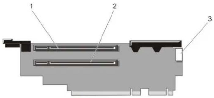
text_image
1 2 3Figure 41. Identifying Connectors on the Expansion Card Riser 3
1 expansion-card slot 6 2 expansion-card slot 7
3 power connector (for GPU cards)
4 If applicable, remove or install an expansion card on the riser.
5 Replace the expansion-card riser.
6 Close the system.
7 Reconnect the system to its electrical outlet and turn the system on, including any attached peripherals.
Installing Expansion-Card Risers

CAUTION: Many repairs may only be done by a certified service technician. You should only perform troubleshooting and simple repairs as authorized in your product documentation, or as directed by the online or telephone service and support team. Damage due to servicing that is not authorized by Dell is not covered by your warranty. Read and follow the safety instructions that came with the product.
1 If applicable, reinstall the expansion card(s) into the expansion card riser.
2 Align the expansion-card riser with the connector and the riser guide pin on the system board.
3 Lower the expansion-card riser into place until the expansion-card riser is fully seated in the connector.
4 Close the system.
5 Reconnect the system to its electrical outlet and turn the system on, including any attached peripherals.
6 Install any device drivers required for the card as described in the documentation for the card.
GPU Card Installation Guidelines

NOTE: Internal GPU cards are supported on the PowerEdge R720 and not on the PowerEdge R720xd.

NOTE: Due to the high power consumption of GPUs, the ambient system inlet temperature is restricted to 30 °C to ensure adequate system cooling when one or more GPU cards are installed in PowerEdge R720. Note that this is less than the standard environmental specification of 35 °C.
- The PowerEdge R720 must be installed with two processors.
- The processor must be of 115 W or less.
- The processor must use a GPU kit low-profile heat sink.
- Ensure the GPU enablement kit is available.
GPU enablement kit includes:
- Low-profile heat sinks
– System board support brackets
- Power cables for the GPU cards
- Filler brackets with closeout EMI shield for unoccupied PCI-e slots
- All GPU cards must be of the same type and model.
- Ensure that your system uses the redundant 1100 W power supplies.
- You can install up to two double-wide GPU cards.
NOTE: Two double-wide GPU cards configuration requires optional riser 3.
- You can install up to four single-wide GPU cards.
Installing A GPU Card

CAUTION: Many repairs may only be done by a certified service technician. You should only perform troubleshooting and simple repairs as authorized in your product documentation, or as directed by the online or telephone service and support team. Damage due to servicing that is not authorized by Dell is not covered by your warranty. Read and follow the safety instructions that came with the product.
1 Turn off the system, including any attached peripherals, and disconnect the system from the electrical outlet and peripherals.
2 Open the system.
3 Unpack the GPU cards and the GPU enablement kit.
4 Attach the system board support bracket for the GPU card to the system chassis using the screw provided in the kit.
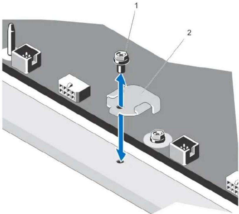
text_image
Technical diagram showing a mechanical assembly with labeled parts and directional arrows indicating movement or force.a screw
b system board support bracket
5 Remove the cooling shroud.
6 Remove the heat sinks.
7 Install the heat sinks from the kit and reinstall the cooling shroud.
8 Connect the GPU power cable/s to the riser card.
9 Unlatch the GPU card lock on the shroud by pushing in the black tab while pulling up the blue card latch.
10 With the blue card latch pulled up, remove the filler brackets for the single- or double-wide GPU cards.
11 Replace the remaining filler brackets with those from the GPU kit.
12 Locate the GPU power connectors on the cable and plug them to the 6-pin and 8-pin connectors on the GPU card.
13 With the GPU card at an angle to the slot on the riser card, insert the connector on the edge of the card into the corresponding connector on the riser slot until the card is fully seated.
NOTE: Ensure the GPU card is installed correctly into the GPU card lock.
14 Press down on the GPU card lock to secure the card in position.
15 Ensure the GPU card is seated into the baffle and press down on the blue dot to close the baffle.
16 Close the system.
Removing A GPU Card
CAUTION: Many repairs may only be done by a certified service technician. You should only perform troubleshooting and simple repairs as authorized in your product documentation, or as directed by the online or telephone service and support team. Damage due to servicing that is not authorized by Dell is not covered by your warranty. Read and follow the safety instructions that came with the product.
1 Turn off the system, including any attached peripherals, and disconnect the system from the electrical outlet and peripherals.
2 Open the system.
3 Lift the GPU-card latch.
4 Open the baffle.
5 Grasp the GPU card by its edges and slide out the GPU card at an angle to release it from the connector on the riser card.
6 Disconnect the cables from the GPU card.
7 If you are removing the card permanently, install a metal filler bracket over the empty slot opening and close the GPU-card latch.
NOTE: You must install a filler bracket over an empty expansion slot to maintain Federal Communications Commission (FCC) certification of the system. The brackets also keep dust and dirt out of the system and aid in proper cooling and airflow inside the system.
8 Close the system.
9 Reconnect the system to its electrical outlet and turn the system on, including any attached peripherals.
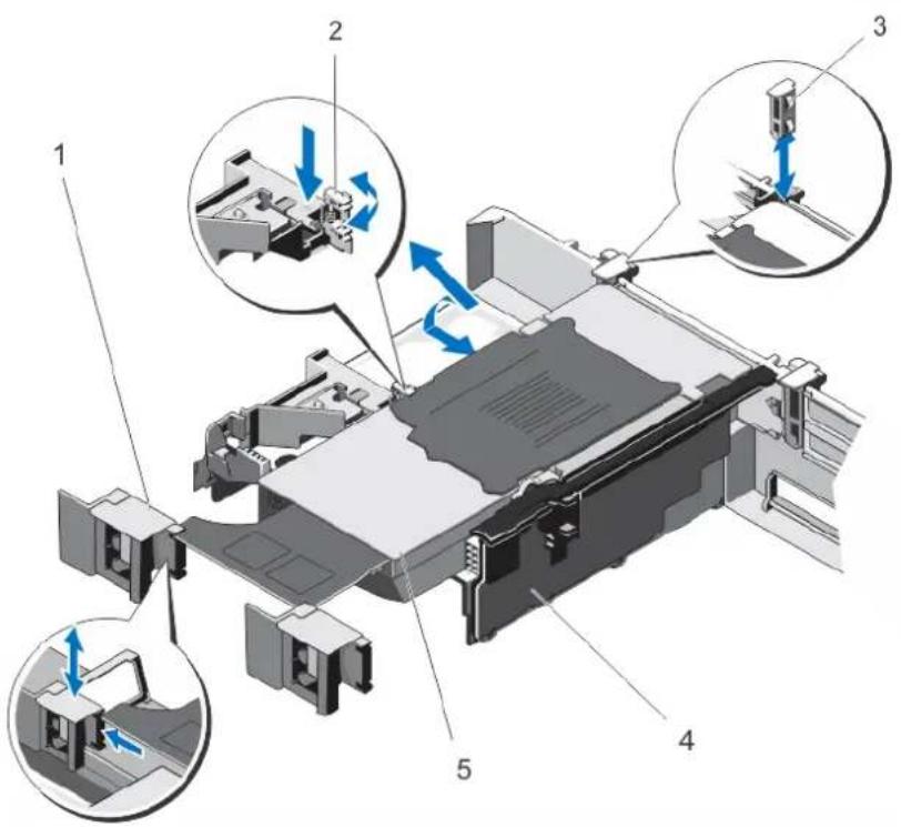
text_image
Technical diagram of a mechanical assembly with numbered components and directional arrows indicating motion or movement.Figure 42. Removing and Installing the GPU Card
1 GPU card latch 2 baffle
3 GPU-card locks 4 expansion-card riser 2
5 GPU card
SD vFlash Card
A vFlash SD card is a Secure Digital (SD) card that plugs into the vFlash SD card slot in the system. It provides persistent on-demand local storage and a custom deployment environment that allows automation of server configuration, scripts, and imaging. It emulates USB device(s). For more information, see the iDRAC7 User's Guide at dell.com/support/manuals.
Replacing An SD vFlash Card
1 Locate the vFlash media slot on the system.
2 To remove the SD vFlash card, push inward on the card to release it, and pull the card from the card slot.
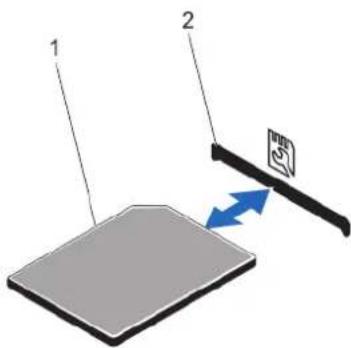
text_image
Diagram showing two labeled components (1 and 2) interacting with a device, with a blue directional arrow indicating flow or movement.Figure 43. Removing and Installing the SD vFlash Card
1 SD vFlash card 2 SD vFlash card slot
3 To install the SD vFlash card, with the label side facing up, insert the contact-pin end of the SD card into the card slot on the module.
NOTE: The slot is keyed to ensure correct insertion of the card.
4 Press inward on the card to lock it into the slot.
Removing The vFlash Media Unit
NOTE: This procedure applies only to PowerEdge R720xd.
CAUTION: Many repairs may only be done by a certified service technician. You should only perform troubleshooting and simple repairs as authorized in your product documentation, or as directed by the online or telephone service and support team. Damage due to servicing that is not authorized by Dell is not covered by your warranty. Read and follow the safety instructions that came with the product.
1 Turn off the system, including any attached peripherals, and disconnect the system from the electrical outlet and peripherals.
2 Open the system.
3 Remove the screw securing the vFlash media unit to the chassis.
4 Remove the cable from the vFlash media unit and the backplane.
5 Slide the vFlash media unit toward front of chassis and lift it out of the system.
6 Close the system.
7 Reconnect the system to its electrical outlet and turn the system on, including any attached peripherals.
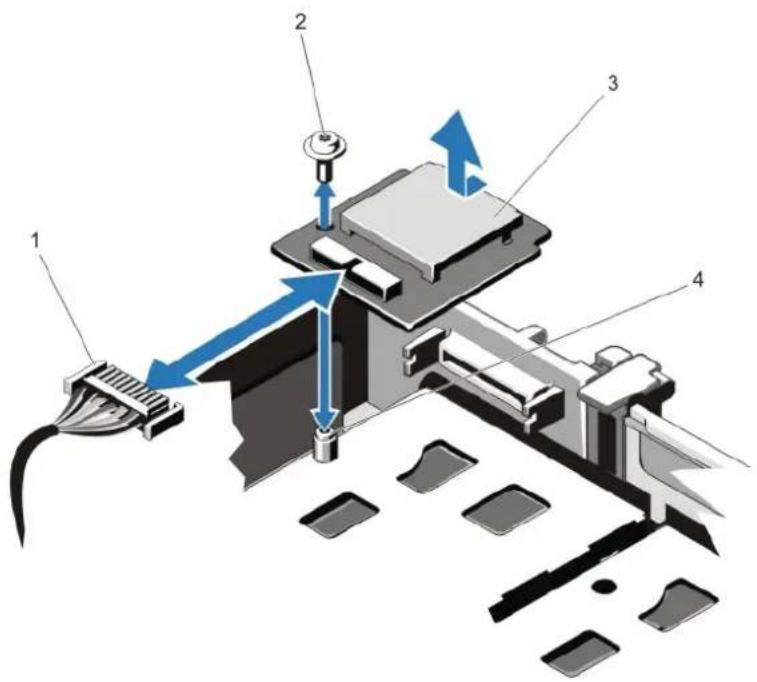
text_image
Technical diagram of a mechanical device with numbered components and directional arrows indicating motion or flow.Figure 44. Removing and Installing the vFlash Media Unit
1 cable 2 screw
3 vFlash media unit 4 standoff
Installing The vFlash Media Unit

NOTE: This procedure applies only to PowerEdge R720xd.

CAUTION: Many repairs may only be done by a certified service technician. You should only perform troubleshooting and simple repairs as authorized in your product documentation, or as directed by the online or telephone service and support team. Damage due to servicing that is not authorized by Dell is not covered by your warranty. Read and follow the safety instructions that came with the product.
1 Turn off the system, including any attached peripherals, and disconnect the system from its electrical outlet.
2 Open the system.
3 Slide in and align the vFlash media unit toward the back of chassis.
4 Connect the cable to the vFlash media unit.
5 Replace the screw securing the vFlash media unit to the chassis.
6 Close the system.
7 Reconnect the system to its electrical outlet and turn the system on, including any attached peripherals.
Internal Dual SD Module

NOTE When the Redundancy option is set to Mirror Mode in the Integrated Devices screen of the System Setup, the information is replicated from one SD card to another.
Removing The Internal Dual SD Module

CAUTION: Many repairs may only be done by a certified service technician. You should only perform troubleshooting and simple repairs as authorized in your product documentation, or as directed by the online or telephone service and support team. Damage due to servicing that is not authorized by Dell is not covered by your warranty. Read and follow the safety instructions that came with the product.
1 Turn off the system, including any attached peripherals, and disconnect the system from the electrical outlet and peripherals.
2 Open the system.
3 Remove the expansion-card riser 3 and any card(s) installed in the riser.
4 Locate the internal dual SD module installed on the J_IDSDM connector on the system board.
5 If applicable, remove the SD card(s).
6 Holding the tab, pull the dual SD module to remove it from the system board.
7 Replace the expansion-card riser 3 and if applicable, replace the card(s) in the riser.
8 Close the system.
9 Reconnect the system to its electrical outlet and turn the system on, including any attached peripherals.
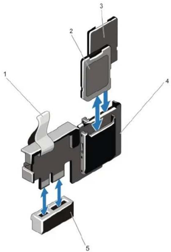
text_image
Technical diagram of a device internal structure with numbered components and blue directional arrows indicating movement or flow.Figure 45. Removing and Installing the Internal Dual SD Module
1 blue pull tab 2 SD card 1
3 SD card 2 4 dual SD module
5 connector on the system board
Installing The Internal Dual SD Module

CAUTION: Many repairs may only be done by a certified service technician. You should only perform troubleshooting and simple repairs as authorized in your product documentation, or as directed by the online or telephone service and support team. Damage due to servicing that is not authorized by Dell is not covered by your warranty. Read and follow the safety instructions that came with the product.
1 Turn off the system, including any attached peripherals, and disconnect the system from the electrical outlet and peripherals.
2 Open the system.
3 Remove the expansion-card riser cage 3 and any card(s) installed in the riser.
4 Locate the J_IDSDM connector on the system board.
5 Align the connectors on the system board and the dual SD module.
6 Holding the tab, push the dual SD module until it is firmly seated on the system board.
7 Replace the expansion-card riser 1 and if applicable, replace the card(s) in the riser.
8 Close the system.
9 Reconnect the system to its electrical outlet and turn the system on, including any attached peripherals.
Internal SD Card
Removing An Internal SD Card

CAUTION: Many repairs may only be done by a certified service technician. You should only perform troubleshooting and simple repairs as authorized in your product documentation, or as directed by the online or telephone service and support team. Damage due to servicing that is not authorized by Dell is not covered by your warranty. Read and follow the safety instructions that came with the product.
1 Turn off the system, including any attached peripherals, and disconnect the system from the electrical outlet and peripherals.
2 Open the system.
3 Remove the expansion-card riser 3 and any card(s) installed in the riser.
4 Locate the SD card slot on the internal dual SD module and press inward on the card to release it from the slot and remove the card.
5 Replace the expansion-card riser 3 and if applicable, replace the card(s) in the riser.
6 Close the system.
7 Reconnect the system to its electrical outlet and turn the system on, including any attached peripherals.
Installing An Internal SD Card

CAUTION: Many repairs may only be done by a certified service technician. You should only perform troubleshooting and simple repairs as authorized in your product documentation, or as directed by the online or telephone service and support team. Damage due to servicing that is not authorized by Dell is not covered by your warranty. Read and follow the safety instructions that came with the product.

NOTE: To use an SD card with your system, ensure that the internal SD card port is enabled in the System Setup.
1 Turn off the system, including any attached peripherals, and disconnect the system from the electrical outlet and peripherals.
2 Open the system.
3 Remove the expansion-card riser 3 and any card(s) installed in the riser.
4 Locate the SD card connector on the internal dual SD module. With the label side facing up, insert the contact-pin end of the card into the slot.
NOTE: The slot is keyed to ensure correct insertion of the card.
5 Press the card into the card slot to lock it into place.
6 Replace the expansion-card riser 3 and if applicable, replace the card(s) in the riser.
7 Close the system.
8 Reconnect the system to its electrical outlet and turn the system on, including any attached peripherals.
Integrated Storage Controller Card
Your system includes a dedicated expansion-card slot on the system board for an integrated controller card that provides the integrated storage subsystem for your system's internal hard drives. The controller supports SAS and SATA hard drives and also enables you to set up the hard drives in RAID configurations as supported by the version of the storage controller included with your system.
Removing The Integrated Storage Controller Card
CAUTION: Many repairs may only be done by a certified service technician. You should only perform troubleshooting and simple repairs as authorized in your product documentation, or as directed by the online or telephone service and support team. Damage due to servicing that is not authorized by Dell is not covered by your warranty. Read and follow the safety instructions that came with the product.
1 Turn off the system, including any attached peripherals, and disconnect the system from the electrical outlet and peripherals.
2 Open the system.
3 Remove the cooling shroud.
4 Remove the expansion-card riser 1.
5 Push down the two release levers at the edge of the card to disengage the card from the connector.
6 Angle the card so that the other end of the card disengages from the storage-controller card holder on the system board.
7 Replace the expansion-card riser 1.
8 Replace the cooling shroud.
9 Close the system.
10 Reconnect the system to its electrical outlet and turn the system on, including any attached peripherals.
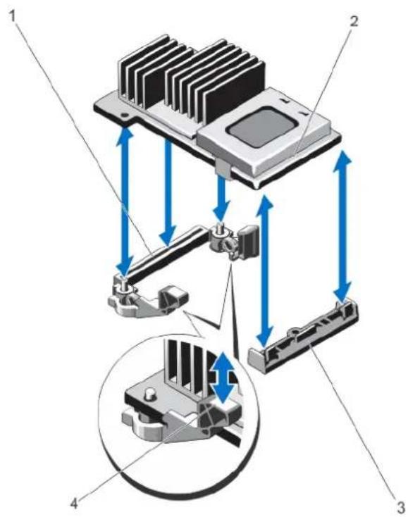
text_image
Technical diagram of a heat sink assembly with labeled components and directional arrows indicating motion or force.Figure 46. Removing and Installing the Integrated Storage Controller Card
1 storage connector on the system board 2 storage controller card
3 storage-controller card holder 4 release levers (2)
Installing The Integrated Storage Controller Card

CAUTION: Many repairs may only be done by a certified service technician. You should only perform troubleshooting and simple repairs as authorized in your product documentation, or as directed by the online or telephone service and support team. Damage due to servicing that is not authorized by Dell is not covered by your warranty. Read and follow the safety instructions that came with the product.
1 Turn off the system, including any attached peripherals, and disconnect the system from the electrical outlet.
2 Open the system.
3 Remove the cooling shroud.
4 Remove the expansion-card riser 1.
5 Align one end of the card with the card holder on the system board.
6 Lower the other end of the card into the storage-controller card holder on the system board.
7 Press the card down until it is fully seated.
When the card is fully seated, the release levers snap over the edge of the card.
8 Replace the expansion-card riser 1.
9 Replace the cooling shroud.
10 Close the system.
11 Reconnect the system to its electrical outlet and turn the system on, including any attached peripherals.
Network Daughter Card
Removing The Network Daughter Card

CAUTION: Many repairs may only be done by a certified service technician. You should only perform troubleshooting and simple repairs as authorized in your product documentation, or as directed by the online or telephone service and support team. Damage due to servicing that is not authorized by Dell is not covered by your warranty. Read and follow the safety instructions that came with the product.
1 Turn off the system, including any attached peripherals, and disconnect the system from the electrical outlet and peripherals.
2 Open the system.
3 If installed, remove expansion card(s) from the expansion-card riser 2.
4 Using a #2 Phillips screwdriver, loosen the two captive screws that secure the network daughter card to the system board.
5 Hold the network daughter card by the edges on either side of the touch point and lift to remove it from the connector on the system board.
6 Slide the network daughter card away from the back of the system until the NIC connectors are clear of the slot in the back panel.
7 Lift the network daughter card out of the chassis.
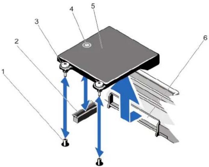
text_image
Technical diagram of a mechanical assembly with numbered components and directional arrows indicating motion or force vectors.Figure 47. Removing and Installing the Network Daughter Card
1 captive screw sockets (2) 2 connector on the system board
3 captive screws (2) 4 touch point
5 network daughter card 6 back panel slot for RJ-45 connectors
Installing The Network Daughter Card

CAUTION: Many repairs may only be done by a certified service technician. You should only perform troubleshooting and simple repairs as authorized in your product documentation, or as directed by the online or telephone service and support team. Damage due to servicing that is not authorized by Dell is not covered by your warranty. Read and follow the safety instructions that came with the product.
1 Angle the card so that the RJ-45 connectors fit through the slot in the back panel.
2 Align the captive screws at back-end of the card with the captive screw sockets on the system board.
3 Press the touch point on the card until the card connector is firmly seated on the system board connector.
4 Using a #2 Phillips screwdriver, tighten the two captive screws to secure the network daughter card to the system board.
5 If applicable, install the expansion card(s) in the expansion-card riser 2.
6 Close the system.
7 Reconnect the system to its electrical outlet and turn the system on, including any attached peripherals.
Processors
Use the following procedure when:
- Installing an additional processor
- Replacing a processor
NOTE: To ensure proper system cooling, you must install a processor blank and a heat-sink blank in any empty processor socket.
Removing A Processor
CAUTION: Many repairs may only be done by a certified service technician. You should only perform troubleshooting and simple repairs as authorized in your product documentation, or as directed by the online or telephone service and support team. Damage due to servicing that is not authorized by Dell is not covered by your warranty. Read and follow the safety instructions that came with the product.
Before upgrading your system, download the latest system BIOS version from support.dell.com and follow the instructions included in the compressed download file to install the update on your system.
NOTE: You can update the system BIOS using the Lifecycle Controller.
2 Turn off the system, including any attached peripherals, and disconnect the system from the electrical outlet. When disconnected from the power source, press and hold the power button for three seconds to fully drain the system of stored power prior to removing the cover.
3 Open the system.
4 Remove the cooling shroud.
WARNING: The heat sink and processor are hot to the touch for some time after the system has been powered down. Allow the heat sink and processor to cool before handling them.
CAUTION: Never remove the heat sink from a processor unless you intend to remove the processor. The heat sink is necessary to maintain proper thermal conditions.
5 Using a #2 Phillips screwdriver, loosen one of the heat-sink retention sockets. Wait 30 seconds for the heat sink to loosen from the processor.
6 Loosen the second heat-sink retention socket.
7 Lift the heat sink away from the processor and set the heat sink aside.
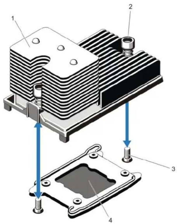
text_image
Technical diagram of a heat exchanger with labeled components and assembly stepsFigure 48. Removing and Installing the Processor Heat Sink
1 heat sink 2 retention sockets (2)
3 retention screws (2) 4 processor
CAUTION: The processor is held in its socket under strong pressure. Be aware that the release lever can spring up suddenly if not firmly grasped.
8 Position your thumb firmly over the processor socket-release lever near the unlock icon and release the lever from the locked position by pushing down and out from under the tab.
9 Similarly, position your thumb firmly over the processor socket-release lever near the lock icon 🔒 and release the lever from the locked position by pushing down and out from under the tab. Rotate the lever 90 degrees upward.

text_image
Technical diagram of a mechanical component with numbered parts and directional arrows indicating movement or assembly.Figure 49. Processor Shield Opening and Closing Lever Sequence
1 close-lock symbol 2 processor socket-release lever
3 processor 4 processor socket-release lever
5 open-lock symbol
10 Rotate the processor shield upward and out of the way.

CAUTION: The socket pins are fragile and can be permanently damaged. Be careful not to bend the pins in the socket when removing the processor out of the socket.
11 Lift the processor out of the socket and leave the release lever up so that the socket is ready for the new processor.

NOTE: If you are permanently removing a processor, you must install a processor/DIMM blank in the vacant socket to ensure proper system cooling. The processor/DIMM blank covers the vacant sockets for the DIMMs and the processor.
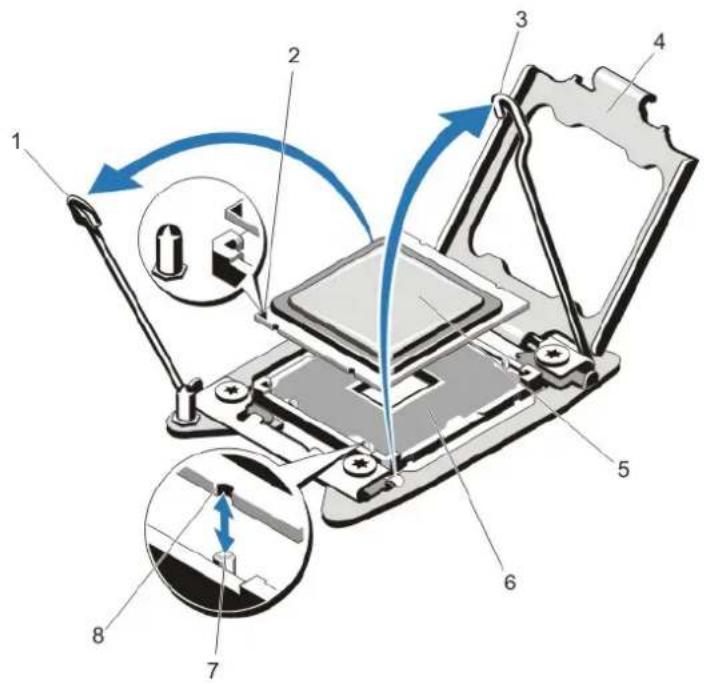
text_image
Technical diagram of a mechanical assembly with numbered components and directional arrows indicating motion or movement.Figure 50. Removing and Installing a Processor
1 processor socket-release lever 2 pin 1 indicator
3 processor socket-release lever 4 processor shield
5 processor 6 ZIF socket
7 socket keys (4) 8 notches in processor (4)
NOTE: After removing the processor, place it in an antistatic container for reuse, return, or temporary storage. Do not touch the bottom of the processor. Touch only the side edges of the processor.
Installing A Processor

CAUTION: Many repairs may only be done by a certified service technician. You should only perform troubleshooting and simple repairs as authorized in your product documentation, or as directed by the online or telephone service and support team. Damage due to servicing that is not authorized by Dell is not covered by your warranty. Read and follow the safety instructions that came with the product.

NOTE: If you are installing a single processor, it must be installed in socket CPU1.
1 Before upgrading your system, download the latest system BIOS version from support.dell.com and follow the instructions included in the compressed download file to install the update on your system.

NOTE: You can update the system BIOS using the Lifecycle Controller.
2 Turn off the system, including any attached peripherals, and disconnect the system from the electrical outlet. When disconnected from the power source, press and hold the power button for three seconds to fully drain the system of stored power prior to removing the cover.
3 Open the system.
4 Remove the cooling shroud.

WARNING: The heat sink and processor are hot to the touch for some time after the system has been powered down. Allow the heat sink and processor to cool before handling them.
CAUTION: Never remove the heat sink from a processor unless you intend to remove the processor. The heat sink is necessary to maintain proper thermal conditions.
5 Remove the heat sink/heat-sink blank and processor/processor blank, as applicable.
NOTE: The procedure to remove the heat-sink blank or processor blank is similar to removing a heat-sink or processor.
6 Unpack the new processor.
7 Align the processor with the socket keys on the ZIF socket.
CAUTION: Positioning the processor incorrectly can permanently damage the system board or the processor. Be careful not to bend the pins in the socket.
CAUTION: Do not use force to seat the processor. When the processor is positioned correctly, it engages easily into the socket.
8 With the release levers on the processor socket in the open position, align pin 1 of the processor, using pin 1 position guide on the socket, as reference and set the processor lightly in the socket.
9 Close the processor shield.
10 Rotate the socket-release lever near the lock icon until it is locked in position.
11 Similarly, rotate the socket-release lever near the unlock icon until it is locked in position.
12 Using a clean lint-free cloth, remove the thermal grease from the heat sink.
CAUTION: Applying too much thermal grease can result in excess grease coming in contact with and contaminating the processor socket.
13 Open the grease applicator included with your processor kit and apply all of the thermal grease in the applicator to the center of the topside of the new processor.
14 Place the heat sink on the processor.
15 Using a #2 Phillips screwdriver, tighten the heat-sink retention sockets.
16 Install the cooling shroud.
17 Close the system.
18 Reconnect your system and peripherals to their electrical outlets, and turn on the system.
19 Press
20 Run the system diagnostics to verify that the new processor operates correctly.
Power Supplies
Your system supports either:
- Two 495 W, 750 W, or 1100 W AC power supply modules or
- Two 750 W or 1100 W DC power supply modules
NOTE: Titanium power supply is nominally rated for 200 VAC to 240 VAC input only.
When two identical power supplies are installed, the power supply configuration is redundant (1 + 1) . In redundant mode, power is supplied to the system equally from both power supplies to maximize efficiency.
When only one power supply is installed, the power supply configuration is non-redundant (1 + 0) . Power is supplied to the system only by the single power supply.
NOTE: If two power supplies are used, they must be of the same type and have the same maximum output power.
Hot Spare Feature
Your system supports the Hot Spare feature that significantly reduces the power overhead associated with power supply redundancy.
When the Hot Spare feature is enabled, a redundant power supply is switched to a sleep state. The active power supply supports 100% of the load, thus operating at higher efficiency. The redundant power supply in the sleep state monitors output voltage of the active power supply. If the output voltage of the active power supply drops, the redundant power supply in the sleep state returns to an active output state.
The active power supply can also activate a sleeping power supply if having both power supplies active is more efficient than having the redundant power supply in a sleep state. The power supply defaults are to wake both power supplies if the load on the active power supply is greater than 50% and to sleep the redundant power supply if the load falls below 20%.
You can configure the Hot Spare feature using the iDRAC settings. For more information on iDRAC settings, see the iDRAC7 User's Guide at dell.com/support/manuals.
Removing An AC Power Supply
CAUTION: Many repairs may only be done by a certified service technician. You should only perform troubleshooting and simple repairs as authorized in your product documentation, or as directed by the online or telephone service and support team. Damage due to servicing that is not authorized by Dell is not covered by your warranty. Read and follow the safety instructions that came with the product.
CAUTION: The system requires one power supply for normal operation. On power-redundant systems, remove and replace only one power supply at a time in a system that is powered on.
NOTE: You may have to unlatch and lift the optional cable management arm if it interferes with power supply removal. For information about the cable management arm, see the system's rack documentation.
1 Disconnect the power cable from the power source and the power supply you intend to remove and remove the cables from the strap.
2 Press the release latch and slide the power supply out of the chassis.
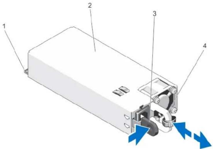
text_image
Diagram of a power supply unit with labeled components and directional arrows indicating flow or movementFigure 51. Removing and Installing an AC Power Supply
1 connector 2 power supply
Installing An AC Power Supply
CAUTION: Many repairs may only be done by a certified service technician. You should only perform troubleshooting and simple repairs as authorized in your product documentation, or as directed by the online or telephone service and support team. Damage due to servicing that is not authorized by Dell is not covered by your warranty. Read and follow the safety instructions that came with the product.
1 Verify that both the power supplies are the same type and have the same maximum output power.
NOTE: The maximum output power (shown in Watts) is listed on the power supply label.
2 If applicable, remove the power supply blank.
3 Slide the new power supply into the chassis until the power supply is fully seated and the release latch snaps into place.
NOTE: If you unlatched the cable management arm, re-latch it. For information about the cable management arm, see the system's rack documentation.
4 Connect the power cable to the power supply and plug the cable into a power outlet.
CAUTION: When connecting the power cable, secure the cable with the strap.
NOTE: When installing, hot-swapping, or hot-adding a new power supply, allow several seconds for the system to recognize the power supply and determine its status. The power-supply status indicator turns green to signify that the power supply is functioning properly.
Wiring Instructions For A DC Power Supply
Your system supports up to two - (48-60) V DC power supplies (when available).
WARNING: For equipment using - (48-60) V DC power supplies, a qualified electrician must perform all connections to DC power and to safety grounds. Do not attempt connecting to DC power or installing grounds yourself. All electrical wiring must comply with applicable local or national codes and practices. Damage due to servicing that is not authorized by Dell is not covered by your warranty. Read and follow all safety instructions that came with the product.
CAUTION: Wire the unit with copper only, unless otherwise specified, use only 10 American Wire Gauge (AWG) wire rated minimum 90 °C for source and return. Protect the - (48–60) V DC (1 wire) with a branch circuit over-current protection rated 50 A for DC with a high interrupt current rating.
CAUTION: Connect the equipment to a -(48 - 60) V DC supply source that is electrically isolated from the AC source (reliably grounded -(48 - 60) V DC SELV source). Ensure that the -(48 - 60) V DC source is efficiently secured to earth (ground).
NOTE: A readily accessible disconnect device that is suitably approved and rated shall be incorporated in the field wiring.
Input Requirements
• Supply voltage: -(48-60) V DC
- Current consumption: 32 A (maximum)
Kit Contents
- Dell part number 6RYJ9 terminal block or equivalent (1)
- #6-32 nut equipped with lock washer (1)
Required Tools
Wire-stripper pliers capable of removing insulation from size 10 AWG solid or stranded, insulated copper wire

NOTE: Use alpha wire part number 3080 or equivalent (65/30 stranding)
Required Wires
• One UL 10 AWG, 2 m maximum (stranded) black wire [-(48-60) V DC]
• One UL 10 AWG, 2 m maximum (stranded) red wire (V DC return)
• One UL 10 AWG, 2 m maximum green/yellow, green with a yellow stripe, stranded wire (safety ground)
Assembling And Connecting The Safety Ground Wire

WARNING: For equipment using - (48-60) V DC power supplies, a qualified electrician must perform all connections to DC power and to safety grounds. Do not attempt connecting to DC power or installing grounds yourself. All electrical wiring must comply with applicable local or national codes and practices. Damage due to servicing that is not authorized by Dell is not covered by your warranty. Read and follow all safety instructions that came with the product.
1 Strip the insulation from the end of the green/yellow wire, exposing approximately 4.5 mm (0.175 inch) of copper wire.
2 Using a hand-crimping tool (Tyco Electronics, 58433-3 or equivalent), crimp the ring-tongue terminal (Jeeson Terminals Inc., R5-4SA or equivalent) to the green/yellow wire (safety ground wire).
3 Connect the safety ground wire to the grounding post on the back of the system using a #6-32 nut equipped with a locking washer.
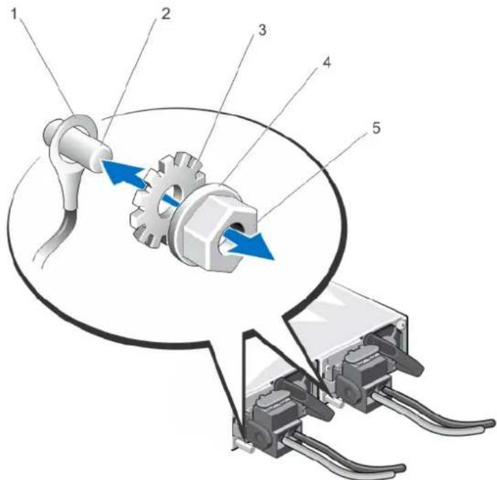
text_image
Technical diagram of a mechanical assembly with numbered components and directional arrows indicating motion or forceFigure 52. Assembling and Connecting the Safety Ground Wire
1 safety ground wire 2 grounding post
3 locking washer 4 spring washer
Assembling The DC Input Power Wires

WARNING: For equipment using - (48-60) V DC power supplies, a qualified electrician must perform all connections to DC power and to safety grounds. Do not attempt connecting to DC power or installing grounds yourself. All electrical wiring must comply with applicable local or national codes and practices. Damage due to servicing that is not authorized by Dell is not covered by your warranty. Read and follow all safety instructions that came with the product.
1 Strip the insulation from the ends of the DC power wires, exposing approximately 13 mm (0.5 inch) of copper wire.
⚠️ WARNING: Reversing polarity when connecting DC power wires can permanently damage the power supply or the system.
2 Insert the copper ends into the mating connectors and tighten the captive screws at the top of the mating connector using a #2 Phillips screwdriver.
WARNING: To protect the power supply from electrostatic discharge, the captive screws must be covered with the rubber cap before inserting the mating connector into the power supply.
3 Rotate the rubber cap clockwise to fix it over the captive screws.
4 Insert the mating connector into the power supply.
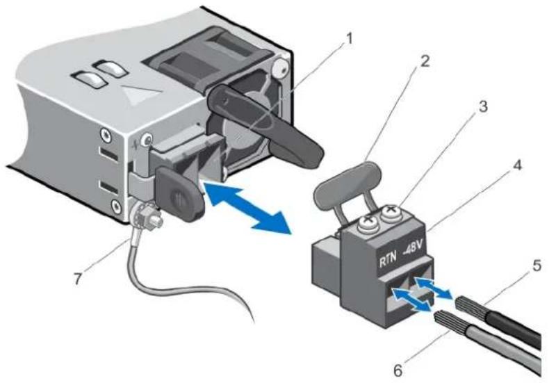
text_image
1 2 3 4 5 6 7 RTN 48VFigure 53. Assembling the DC Input Power Wires
1 DC power socket 2 rubber cap
3 captive screws (2) 4 DC power connector
5 wire -48 V 6 wire RTN
7 grounding wire
Removing A DC Power Supply

WARNING: For equipment using -(48-60) V DC power supplies, a qualified electrician must perform all connections to DC power and to safety grounds. Do not attempt connecting to DC power or installing grounds yourself. All electrical wiring must comply with applicable local or national codes and practices. Damage due to servicing that is not authorized by Dell is not covered by your warranty. Read and follow all safety instructions that came with the product.
CAUTION: The system requires one power supply for normal operation. On power-redundant systems, remove and replace only one power supply at a time in a system that is powered on.
NOTE: You may have to unlatch and lift the optional cable management arm if it interferes with power supply removal. For information about the cable management arm, see the system's rack documentation.
1 Disconnect the power wires from the power source and the connector from the power supply you intend to remove.
2 Disconnect the safety ground wire.
3 Press the release latch and slide the power supply out of the chassis.
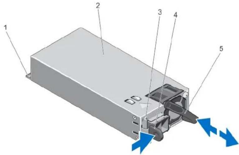
text_image
Diagram of an electronic device showing labeled components and directional arrows indicating flow or movement.Figure 54. Removing and Installing a DC Power Supply
1 connector 2 power supply
3 power supply status indicator 4 release latch
5 power supply handle
Installing A DC Power Supply
WARNING: For equipment using - (48-60) V DC power supplies, a qualified electrician must perform all connections to DC power and to safety grounds. Do not attempt connecting to DC power or installing grounds yourself. All electrical wiring must comply with applicable local or national codes and practices. Damage due to servicing that is not authorized by Dell is not covered by your warranty. Read and follow all safety instructions that came with the product.
1 Verify that both the power supplies are the same type and have the same maximum output power.
NOTE: The maximum output power (shown in Watts) is listed on the power supply label.
2 If applicable, remove the power supply blank.
3 Slide the new power supply into the chassis until the power supply is fully seated and the release latch snaps into place.
NOTE: If you unlatched the cable management arm, re-latch it. For information about the cable management arm, see the system's rack documentation.
4 Connect the safety ground wire.
5 Install the DC power connector in the power supply.
△|CAUTION: When connecting the power wires, secure the wires with the strap to the power supply handle.
6 Connect the wires to a DC power source.
NOTE: When installing, hot-swapping, or hot-adding a new power supply, allow several seconds for the system to recognize the power supply and determine its status. The power-supply status indicator turns green to signify that the power supply is functioning properly.
Removing The Power Supply Blank

CAUTION: To ensure proper system cooling, the power supply blank must be installed in the second power supply bay in a non-redundant configuration. Remove the power supply blank only if you are installing a second power supply.
If you are installing a second power supply, remove the power supply blank in the bay by pulling outward on the blank.
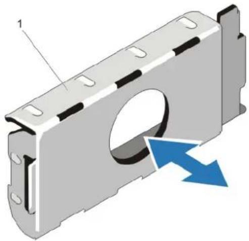
natural_image
3D diagram of a mechanical component with a highlighted cavity and blue directional arrows indicating flow or movement (no text or symbols)Figure 55. Removing and Installing the Power Supply Blank
1 power supply blank
Installing The Power Supply Blank

NOTE: Install the power supply blank only in the second power supply bay.
To install the power supply blank, align the blank with the power supply bay and insert it into the chassis until it clicks into place.
System Battery
Replacing The System Battery

WARNING: There is a danger of a new battery exploding if it is incorrectly installed. Replace the battery only with the same or equivalent type recommended by the manufacturer. See your safety information for additional information.

CAUTION: Many repairs may only be done by a certified service technician. You should only perform troubleshooting and simple repairs as authorized in your product documentation, or as directed by the online or telephone service and support team. Damage due to servicing that is not authorized by Dell is not covered by your warranty. Read and follow the safety instructions that came with the product.
1 Turn off the system, including any attached peripherals, and disconnect the system from the electrical outlet and peripherals.
2 Open the system.
3 Remove the cooling shroud.
4 Locate the battery socket.

CAUTION: To avoid damage to the battery connector, you must firmly support the connector while installing or removing a battery.
5 To remove the battery, support the battery connector by pressing down firmly on the positive side of the connector.
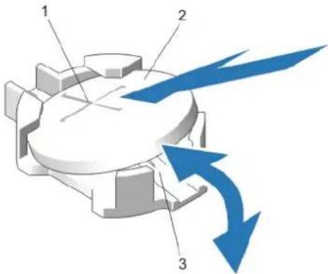
text_image
Diagram of a mechanical component with labeled parts and directional arrows indicating flow or movementFigure 56. Replacing the System Battery
1 positive side of battery connector 2 system battery
3 negative side of battery connector
6 Lift the battery out of the securing tabs at the negative side of the connector.
7 To install a new system battery, support the battery connector by pressing down firmly on the positive side of the connector.
8 Hold the battery with the "+" facing up and slide it under the securing tabs at the positive side of the connector.
9 Press the battery straight down into the connector until it snaps into place.
10 Install the cooling shroud.
11 Close the system.
12 Reconnect the system to the electrical outlet and turn the system on, including any attached peripherals.
13 Enter the System Setup to confirm that the battery is operating properly.
14 Enter the correct time and date in the System Setup Time and Date fields.
15 Exit the System Setup.
Hard-Drive Backplane
Depending on your system configuration:
PowerEdge R720 supports
2.5 inch (x16) SAS/SATA backplane or
dual 2.5 inch (x8) SAS/SATA backplanes or
2.5 inch (x8) SAS/SATA backplane and 2.5 inch (x4) Dell PowerEdge Express Flash (PCIe SSD) backplane or
3.5 inch (x8) SAS/SATA backplane or
no backplane
PowerEdge R720xd supports
2.5 inch (x24) SAS/SATA backplane and optional 2.5 inch (x2) SAS/SSD backplane (back) or
3.5 inch (x12) SAS/SATA backplane and optional 2.5 inch (x2) SAS/SSD backplane (back)
Removing The Hard-Drive Backplane

CAUTION: Many repairs may only be done by a certified service technician. You should only perform troubleshooting and simple repairs as authorized in your product documentation, or as directed by the online or telephone service and support team. Damage due to servicing that is not authorized by Dell is not covered by your warranty. Read and follow the safety instructions that came with the product.
1 If installed, remove the front bezel
2 Turn off the system, including any attached peripherals, and disconnect the system from the electrical outlet.
3 Open the system.

CAUTION: To prevent damage to the drives and backplane, you must remove the hard drives from the system before removing the backplane.

CAUTION: You must note the number of each hard drive and temporarily label them before removal so that you can replace them in the same locations.
4 Remove the cooling shroud.
5 Remove the cooling-fan assembly.
6 Remove all hard drives.
7 Disconnect the SAS/SATA/SSD data, signal, and power cable(s) from the backplane.
8 Press the release tabs and slide the backplane upward.
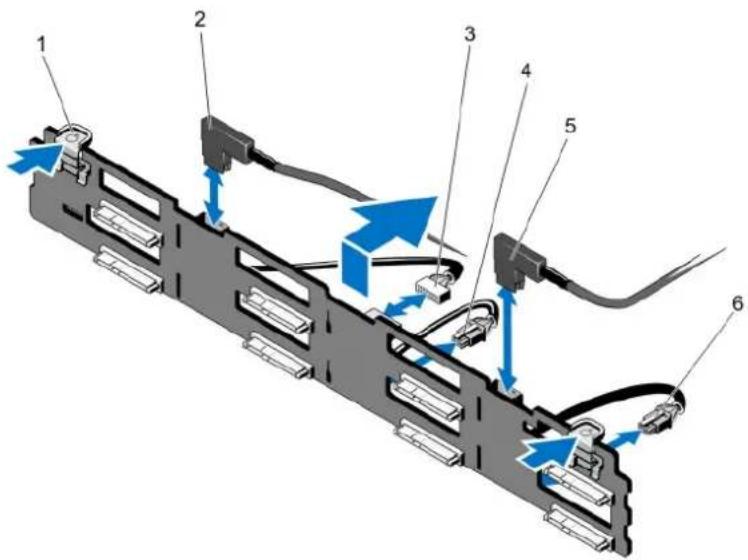
text_image
Diagram of a server rack with labeled components and blue directional arrows indicating cable or connection paths.Figure 57. Removing and Installing the 3.5 Inch (x8) SAS/SATA Backplane—PowerEdge R720
1 release tabs (2) 2 SAS A cable
3 backplane signal cable 4 backplane power cable A
5 SAS B cable 6 backplane power cable B
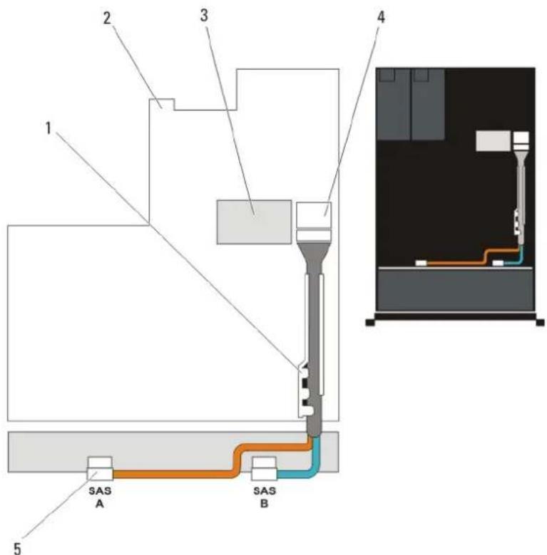
text_image
1 2 3 4 SAS A SAS B 5Figure 58. Cabling Diagram—3.5 Inch (x8) SAS/SATA Backplane—PowerEdge R720
1 cable retention bracket 2 system board
3 integrated storage controller card 4 SAS connector (mini PERC SAS) on the system board
5 SAS connectors on the backplane (2)
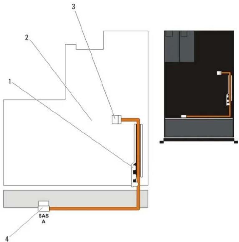
text_image
1 2 3 4 SAS AFigure 59. Cabling Diagram—3.5 Inch (x4) SAS/SATA Backplane—PowerEdge R720
1 cable retention bracket 2 system board
3 SAS connector on the system board 4 SAS connector on the backplane
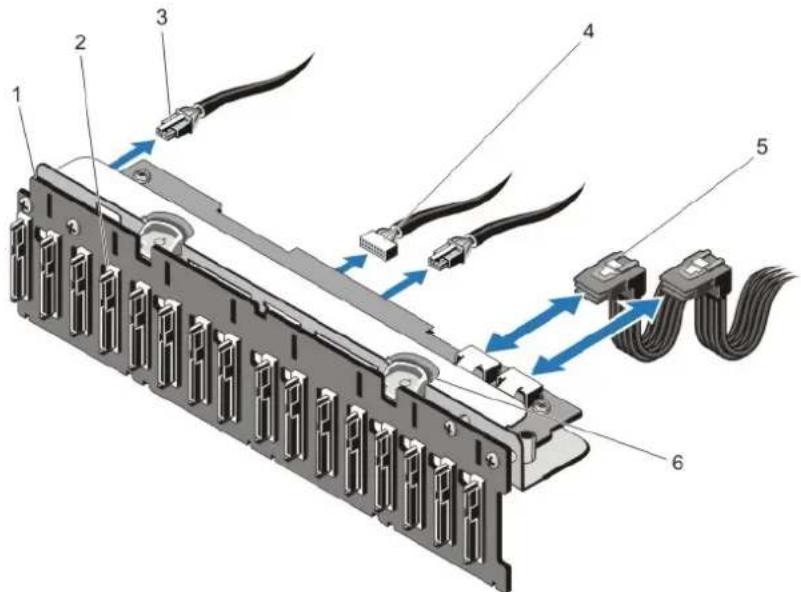
text_image
Diagram of a computer RAM module with labeled components and cable connectionsFigure 60. Removing and Installing the 2.5 Inch (x16) SAS/SATA Backplane—PowerEdge R720
1 x16 hard-drive backplane 2 hard-drive backplane connectors (16)
3 backplane power cables (2) 4 backplane signal cable 5 SAS cables (2) 6 release tabs (2)
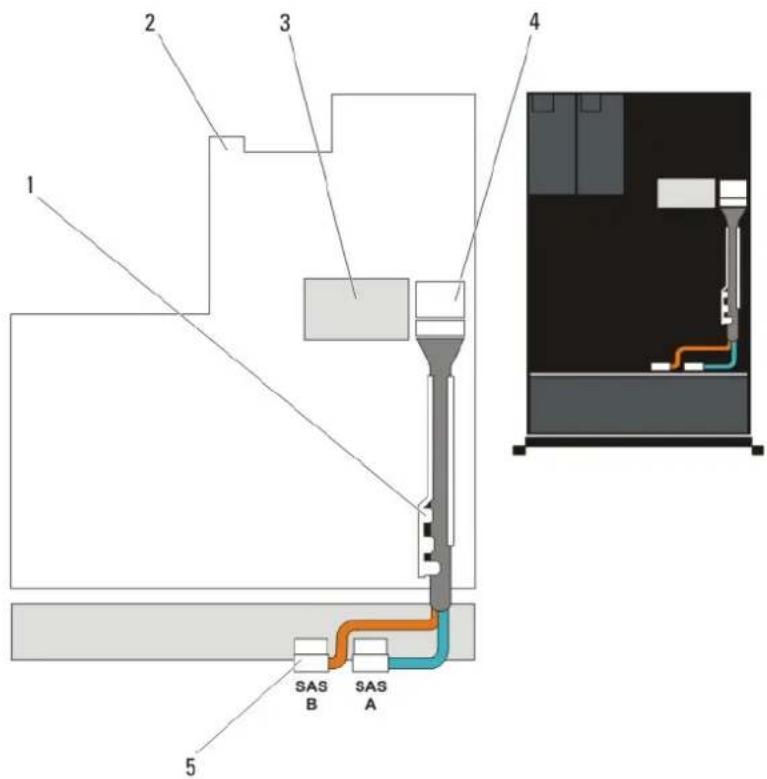
text_image
1 2 3 4 SAS B SAS A 5Figure 61. Cabling Diagram—2.5 Inch (x16) SAS/SATA Backplane—PowerEdge R720
1 cable retention bracket 2 system board
3 integrated storage controller card 4 SAS connector on the system board
5 SAS connectors on the backplane (2)
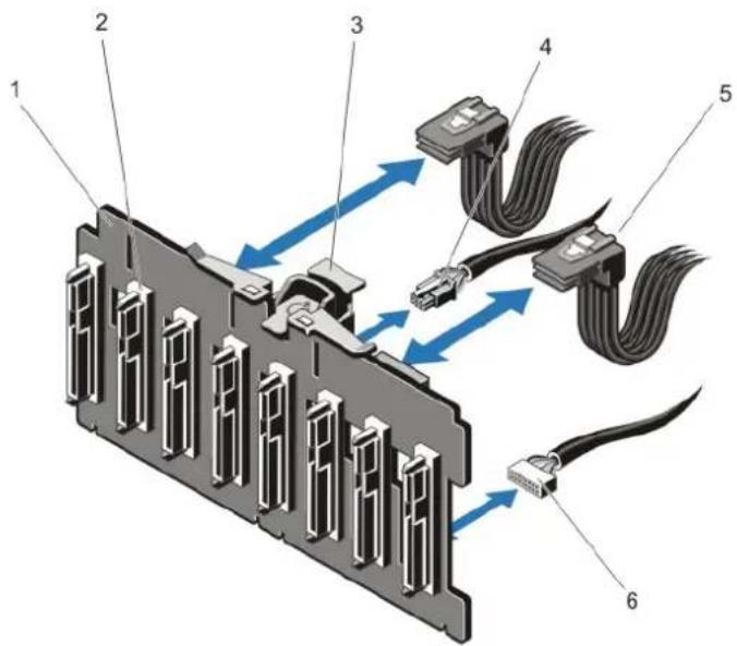
text_image
Diagram of a computer RAM module with labeled components and signal flow arrowsFigure 62. Removing and Installing the 2.5 Inch (x8) SAS/SATA Backplane—PowerEdge R720
1 x8 hard-drive backplane 2 hard-drive backplane connectors (8)
3 release tab 4 backplane power cable
5 SAS cables (2) 6 backplane signal cable
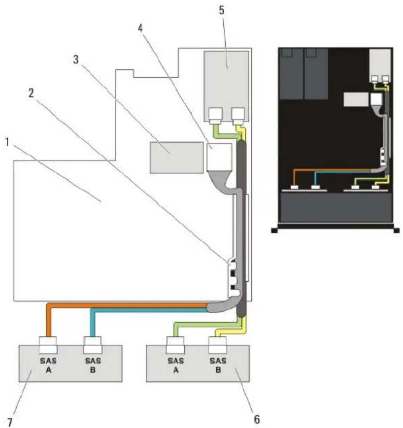
text_image
1 2 3 4 5 6 7 SAS A SAS B SAS A SAS BFigure 63. Cabling Diagram—Dual 2.5 Inch (x8) SAS/SATA Backplane—PowerEdge R720
1 system board 2 cable retention bracket
3 integrated storage controller card 4 SAS connector on the system board
5 SAS controller card 6 SAS backplane
7 SAS backplane
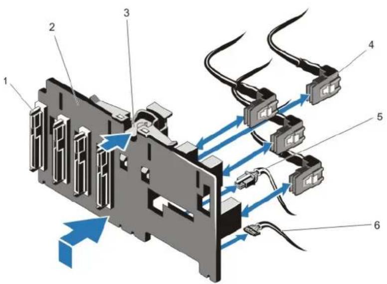
text_image
Diagram of a computer RAM module with labeled components and airflow direction arrowsFigure 64. Removing and Installing the 2.5 Inch (x4) SSD/Dell PowerEdge Express Flash (PCIe SSD) Backplane—PowerEdge R720
1 hard-drive backplane connectors (4) 2 x4 hard-drive backplane
3 release tab 4 SSD/PCIe SSD cables (4)
5 backplane power cable 6 backplane signal cable
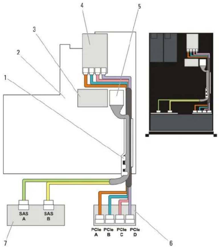
text_image
1 2 3 4 5 6 7 SAS A SAS B PCIe A PCIe B PCIe C PCIe DFigure 65. Cabling Diagram—2.5 Inch (x8) SAS/SATA and (x4) PCIe SSD Backplane—PowerEdge R720
1 cable retention bracket 2 system board
3 integrated storage controller card 4 SSD/PCIe SSD controller card
5 SAS connector on the system board 6 SSD/PCIe SSD backplane
7 SAS backplane
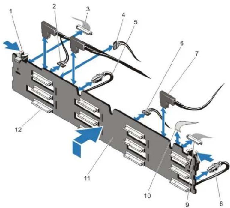
text_image
Technical diagram of a server rack with numbered components and blue directional arrows indicating flow or movement.Figure 66. Removing and Installing the 3.5 Inch (x12) SAS/SATA Backplane—PowerEdge R720xd
1 release tabs (2) 2 pass-through I2C cable
3 left control panel cable 4 I2C cable
5 power cable A 6 USB cable
7 SAS cables (3) 8 power cable B
9 front I/O cable 10 right control panel cable
11 x 12 hard-drive backplane 12 hard-drive backplane connectors (12)
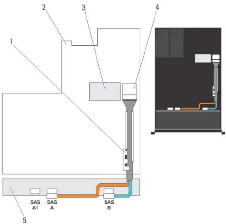
text_image
1 2 3 4 5 SAS A1 SAS A SAS BFigure 67. Cabling Diagram—3.5 linch (x12) SAS/SATA Backplane—PowerEdge R720xd
1 cable retention bracket 2 system board
3 integrated storage controller card 4 SAS connector on the system board
5 SAS backplane
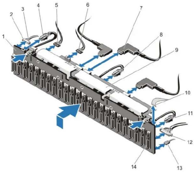
text_image
Technical diagram of a battery internal structure with numbered components and blue directional arrows indicating flow or movement.Figure 68. Removing and Installing the 2.5 Inch (x24) SAS/SATA Backplane—PowerEdge R720xd
1 x24 hard-drive backplane 2 left control panel cable
3 release tabs (2) 4 power cable A
5 sideband cable 6 pass-through I2C cable
7 SAS cables (3) 8 power cable B
9 backplane/expander bracket 10 right control panel cable
11 power cable C 12 front I/O cable
13 USB cable 14 hard-drive backplane connectors (24)
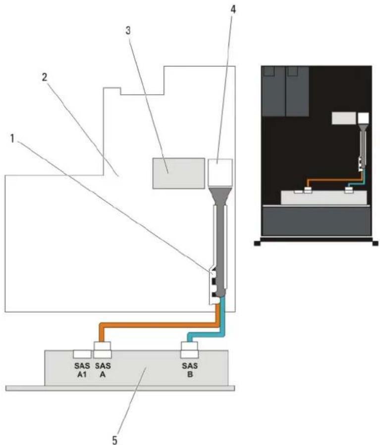
text_image
1 2 3 4 5 SAS A1 SAS A SAS BFigure 69. Cabling Diagram—2.5 Inch (x24) SAS/SATA Backplane—PowerEdge R720xd
1 cable retention bracket 2 system board
3 integrated storage controller card 4 SAS connector on the system board
5 SAS backplane
Installing The Hard-Drive Backplane

CAUTION: Many repairs may only be done by a certified service technician. You should only perform troubleshooting and simple repairs as authorized in your product documentation, or as directed by the online or telephone service and support team. Damage due to servicing that is not authorized by Dell is not covered by your warranty. Read and follow the safety instructions that came with the product.
1 Use the hooks at the base of the chassis as guides to align the hard-drive backplane.
2 Slide down the hard-drive backplane until the release tabs snap into place.
3 Connect the SAS/SATA/SSD data, signal, and power cable(s) to the backplane.
4 Replace the cooling-fan assembly.
5 Replace the cooling shroud.
6 Install the hard drives in their original locations.
7 Close the system.
8 Reconnect the system to its electrical outlet and turn the system on, including any attached peripherals.
9 If applicable, install the front bezel.
Removing The Optional Hard-Drive Backplane (Back)

NOTE: This procedure applies only to PowerEdge R720xd.

CAUTION: Many repairs may only be done by a certified service technician. You should only perform troubleshooting and simple repairs as authorized in your product documentation, or as directed by the online or telephone service and support team. Damage due to servicing that is not authorized by Dell is not covered by your warranty. Read and follow the safety instructions that came with the product.
1 Turn off the system, including any attached peripherals, and disconnect the system from the electrical outlet.
2 Open the system.

CAUTION: To prevent damage to the drives and backplane, you must remove the hard drives from the system before removing the backplane.

CAUTION: You must note the number of each hard drive and temporarily label them before removal so that you can replace them in the same locations.
3 Remove both hard drives.
4 Disconnect all the cables from the backplane.
5 Lift the release pin and slide the backplane away from the chassis.
6 Lift the backplane to remove it from the chassis.
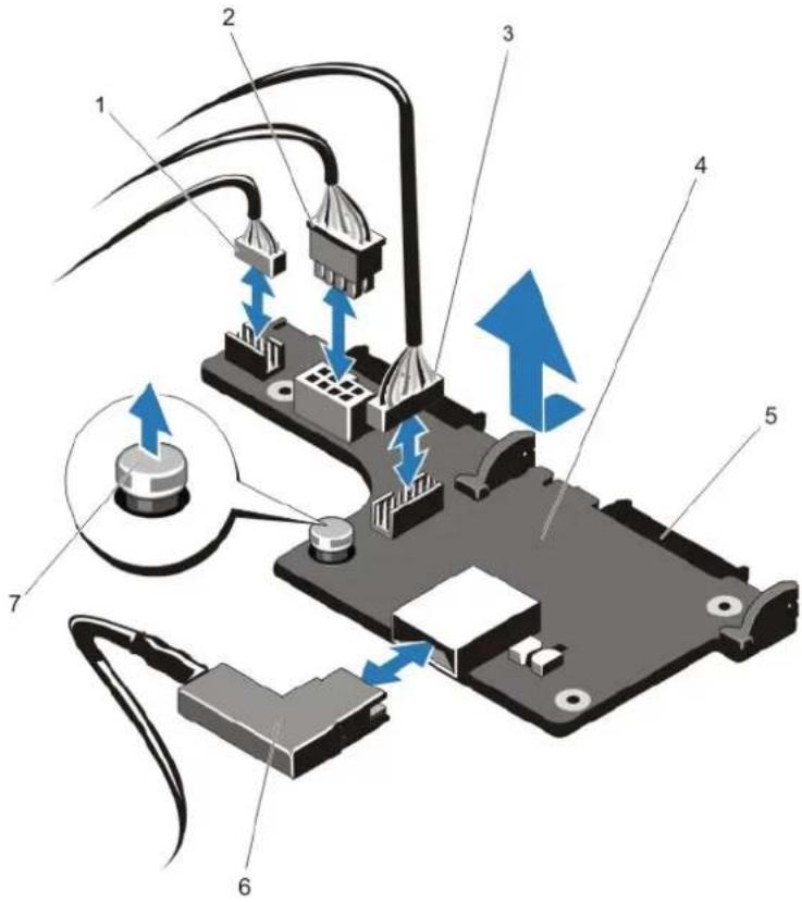
text_image
Diagram of an electronic device with numbered components and blue directional arrows indicating movement or operation.Figure 70. Removing and Installing the Optional 2.5 Inch (x2) Hard-Drive Backplane—PowerEdge R720xd
3 sideband cable 4 hard-drive backplane (back)
5 SAS/SATA connectors (2) 6 SAS cable
7 release pin
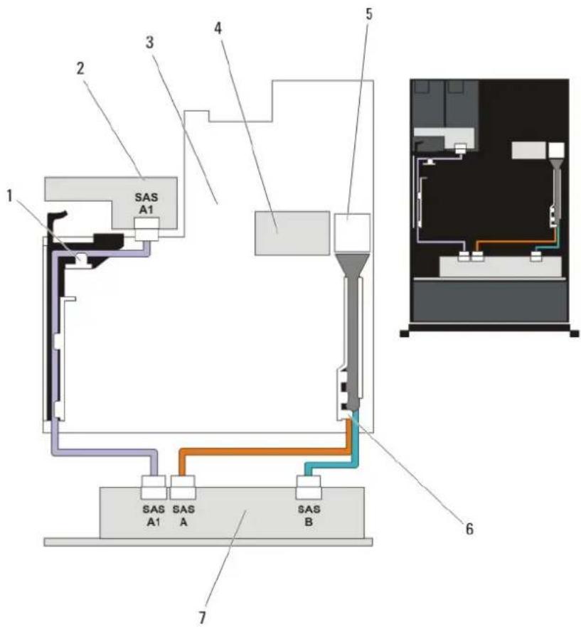
text_image
1 2 3 4 5 SAS A1 SAS A1 SAS A SAS B 6 7Figure 71. Cabling Diagram—Optional 2.5 Inch (x2) Hard-Drive Backplane (back) —PowerEdge R720xd
1 PCIe card holder 2 hard-drive backplane (back)
3 system board 4 integrated storage controller card
5 SAS connector on the system board 6 cable retention bracket
7 x12 or x24 hard-drive backplane
Installing The Optional Hard-Drive Backplane (Back)

NOTE: This procedure applies only to PowerEdge R720xd.

CAUTION: Many repairs may only be done by a certified service technician. You should only perform troubleshooting and simple repairs as authorized in your product documentation, or as directed by the online or telephone service and support team. Damage due to servicing that is not authorized by Dell is not covered by your warranty. Read and follow the safety instructions that came with the product.
1 Turn off the system, including any attached peripherals, and disconnect the system from the electrical outlet.
2 Open the system.
3 Align the notches on the backplane with the notches on the chassis.
4 Lift the release pin and slide the backplane on the chassis until firmly seated.
5 Release the release pin to lock the backplane to the chassis.
6 Reconnect all the cables to the backplane.
7 Install both the hard drives in their original location.
8 Close the system.
9 Reconnect the system to its electrical outlet and turn the system on, including any attached peripherals.
Control Panel Board
Removing The Control Panel (PowerEdge R720)

CAUTION: Many repairs may only be done by a certified service technician. You should only perform troubleshooting and simple repairs as authorized in your product documentation, or as directed by the online or telephone service and support team. Damage due to servicing that is not authorized by Dell is not covered by your warranty. Read and follow the safety instructions that came with the product.
1 If installed, remove the front bezel.
2 Turn off the system, including any attached peripherals, and disconnect the system from the electrical outlet and peripherals.
3 Open the system.
4 Using a #2 Phillips screwdriver, remove the screw(s) securing the control panel to the chassis.

CAUTION: Do not use excessive force when removing the control panel as it can damage the connectors.
5 From inside the system, push the front panel out of the chassis.
6 Remove all the cables connecting the control panel to the chassis.
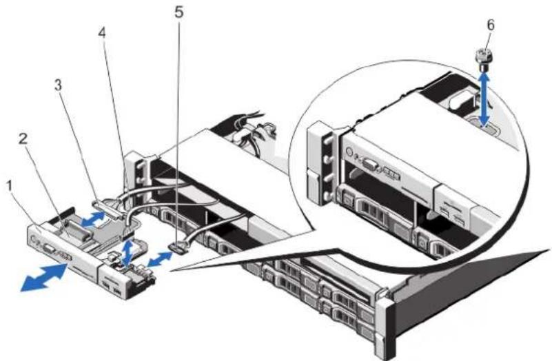
text_image
Diagram of a computer drive system with numbered components and a magnified view showing internal components.Figure 72. Removing and Installing the Control Panel—3.5 inch Hard Drives—PowerEdge R720
1 control panel 2 control-panel board
3 control-panel connector cable 4 USB connector cable
5 vFlash media connector cable 6 screw
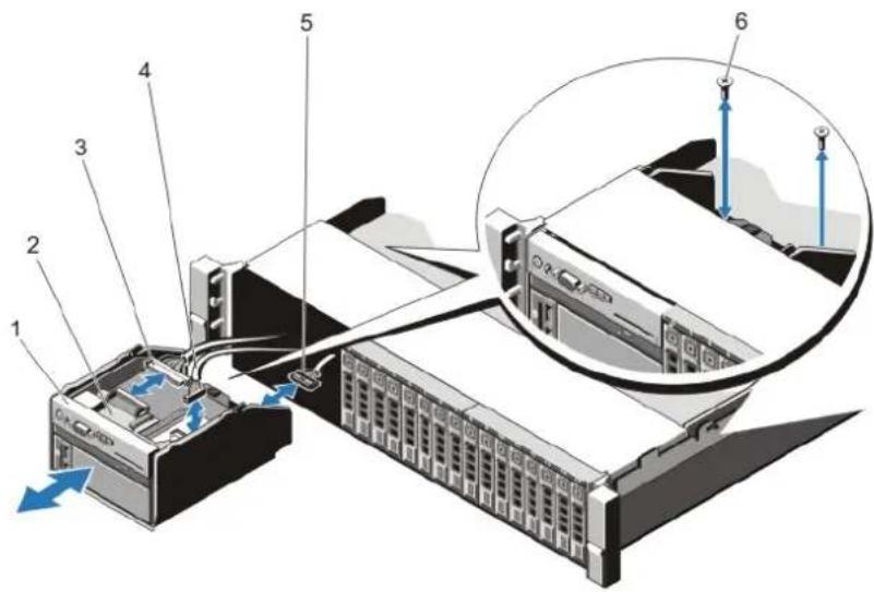
text_image
Diagram of a server rack with numbered components and a magnified inset showing cable routing or connection details.Figure 73. Removing and Installing the Control Panel—2.5 inch Hard Drives—PowerEdge R720
1 control panel 2 control-panel board
3 control-panel connector cable 4 USB connector cable
5 vFlash media connector cable 6 screws (2)
7 Locate and press the tabs on the information tag.
8 Push the information tag out of the slot to remove it from the control panel.
NOTE: Retain the information tag for replacement in the new control panel.
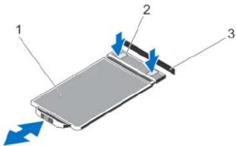
text_image
Diagram of a device with labeled components and directional arrows indicating movement or flowFigure 74. Removing and Installing the Information Tag
1 information tag 2 tabs (2)
3 slot
Installing The Control Panel (PowerEdge R720)
CAUTION: Many repairs may only be done by a certified service technician. You should only perform troubleshooting and simple repairs as authorized in your product documentation, or as directed by the online or telephone service and support team. Damage due to servicing that is not authorized by Dell is not covered by your warranty. Read and follow the safety instructions that came with the product.
1 Replace the blank information tag in the new control panel with the information tag retained from the old control panel.
NOTE: Information tag lists system information such as Service Tag, NIC, MAC address, and so on.
2 To install the information tag, push the information tag into the control-panel slot.
3 Connect all the applicable cables to the control panel.
4 Insert the control panel into the slot in the chassis and secure the module with the screw.
5 Close the system.
6 Reconnect the system and peripherals to their power sources, and turn them on.
7 If applicable, install the front bezel.
Removing The Control Panel (PowerEdge R720xd)

CAUTION: Many repairs may only be done by a certified service technician. You should only perform troubleshooting and simple repairs as authorized in your product documentation, or as directed by the online or telephone service and support team. Damage due to servicing that is not authorized by Dell is not covered by your warranty. Read and follow the safety instructions that came with the product.
1 If installed, remove the front bezel.
2 Turn off the system, including any attached peripherals, and disconnect the system from the electrical outlet and peripherals.
3 Open the system.

CAUTION: Do not use excessive force when removing the control panel cable as it can damage the connectors.
4 Disconnect the control panel cable from the backplane by pulling on the pull tab.
5 Remove the three Torx screws that secure the I/O panel to the chassis.
6 Fold the pull tab close to the connector.
7 Pull out the control panel cable as you guide the connector and the pull tab through the channel on the chassis.
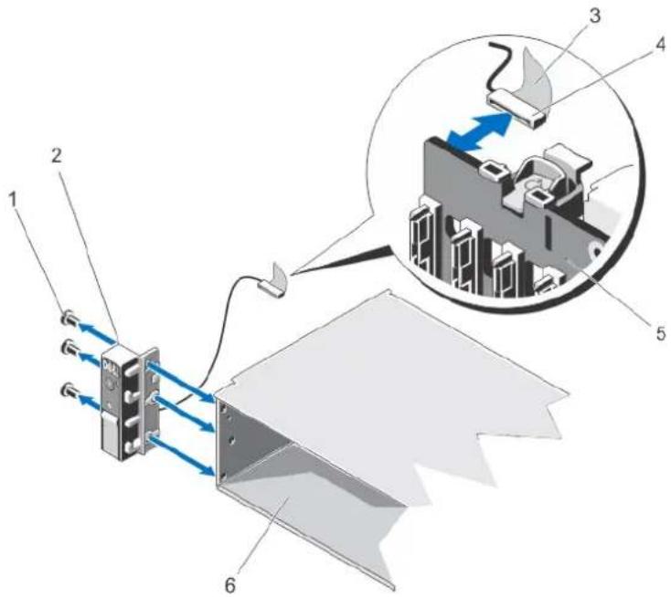
text_image
Diagram of an electrical device with labeled components and a magnified inset showing internal components.Figure 75. Removing and Installing the Control Panel—PowerEdge R720xd
1 Torx screws (3) 2 control panel
3 pull tab 4 connector
5 hard-drive backplane 6 chassis
Installing The Control Panel (PowerEdge R720xd)

CAUTION: Many repairs may only be done by a certified service technician. You should only perform troubleshooting and simple repairs as authorized in your product documentation, or as directed by the online or telephone service and support team. Damage due to servicing that is not authorized by Dell is not covered by your warranty. Read and follow the safety instructions that came with the product.
1 If installed, remove the front bezel.
2 Turn off the system, including any attached peripherals, and disconnect the system from the electrical outlet and peripherals.
3 Open the system.
4 Fold the label around the cable.
5 Fold the pull tab close to the connector and guide the connector and pull tab into the channel.
6 Push the cable until the cable passes completely through the channel.
7 Tighten the three Torx screws to secure the control panel to the chassis.
NOTE: You must route the cable properly to prevent it from being pinched or crimped.
8 Connect the cable connector on the backplane by pushing on the center of the connector.
9 Close the system.
10 Reconnect the system to its electrical outlet and turn the system on, including any attached peripherals.
11 If applicable, install the front bezel.
Removing The I/O Panel (PowerEdge R720xd)

CAUTION: Many repairs may only be done by a certified service technician. You should only perform troubleshooting and simple repairs as authorized in your product documentation, or as directed by the online or telephone service and support team. Damage due to servicing that is not authorized by Dell is not covered by your warranty. Read and follow the safety instructions that came with the product.
1 If installed, remove the front bezel.
2 Turn off the system, including any attached peripherals, and disconnect the system from the electrical outlet and peripherals.
3 Open the system.

CAUTION: To prevent damage to the I/O cable, you must release the locking tab before removing or installing the I/O cable from the connector on the hard-drive backplane.
4 Rotate the locking tab on the I/O cable connector clockwise 90 degrees to release the lock.
5 Disconnect the I/O cable from the backplane.
6 Remove the three Torx screws securing the I/O panel to the chassis.
7 Pull out the I/O panel cable through the channel on the chassis.
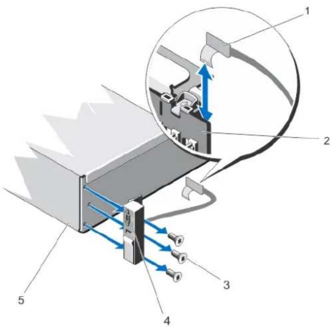
text_image
Technical diagram of a mechanical device with labeled components and directional arrows indicating flow or movement.Figure 76. Removing and Installing the I/O Panel —PowerEdge R720xd
1 I/O panel cable 2 hard-drive backplane
3 Torx screws (3) 4 I/O panel
5 chassis
Installing The I/O Panel (PowerEdge R720xd)

CAUTION: Many repairs may only be done by a certified service technician. You should only perform troubleshooting and simple repairs as authorized in your product documentation, or as directed by the online or telephone service and support team. Damage due to servicing that is not authorized by Dell is not covered by your warranty. Read and follow the safety instructions that came with the product.
1 If installed, remove the front bezel.
2 Turn off the system, including any attached peripherals, and disconnect the system from the electrical outlet and peripherals.
3 Open the system.
4 Fold the label around the cable.
5 Push the cable until the cable passes completely through the channel.

CAUTION: To prevent damage to the I/O cable, you must release the locking tab before removing or installing the I/O cable from the connector on the hard-drive backplane.
6 If locked, rotate the locking tab on the I/O cable connector clockwise 90 degrees to release the lock.
7 Connect the I/O panel cable to the connector on the hard-drive backplane.
8 Rotate the locking tab on the I/O cable connector counter clockwise 90 degrees to secure the lock.
9 Tighten the three Torx screws to secure the control panel to the chassis.

NOTE: You must route the cable properly to prevent it from being pinched or crimped.
10 Close the system.
11 Reconnect the system to its electrical outlet and turn the system on, including any attached peripherals.
12 If applicable, install the front bezel.
System Board
Removing The System Board
CAUTION: Many repairs may only be done by a certified service technician. You should only perform troubleshooting and simple repairs as authorized in your product documentation, or as directed by the online or telephone service and support team. Damage due to servicing that is not authorized by Dell is not covered by your warranty. Read and follow the safety instructions that came with the product.
CAUTION: If you are using the Trusted Program Module (TPM) with an encryption key, you may be prompted to create a recovery key during program or System Setup. Be sure to create and safely store this recovery key. If you replace this system board, you must supply the recovery key when you restart your system or program before you can access the encrypted data on your hard drives.
1 Turn off the system, including any attached peripherals, and disconnect the system from the electrical outlet.
2 If installed, remove the front bezel.
3 Open the system.
4 Remove the following:
a cooling shroud
b cooling-fan assembly
c power supply(s)
d all expansion-card risers
e integrated storage controller card
f internal dual SD module
g internal USB key (if installed)
h PCIe card holder
i cable retention bracket
j if present, support bracket
NOTE: The support bracket is present on certain system configurations for protection during shipping and can be discarded after removal.
CAUTION: To avoid damaging the mini SAS cable and connector, follow the correct procedure when removing the mini SAS cable from the system board.
5 Disconnect the mini SAS cable from the system board:
a Push the mini SAS cable connector to slide it further into the connector (J_SASX8) on the system board.
b Press down and hold the metal tab on the mini SAS cable connector.
c Pull the mini SAS cable out of the connector on the system board.
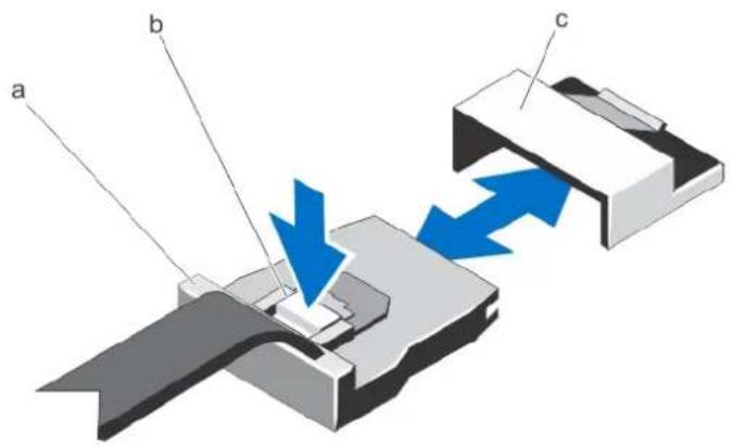
text_image
a b ca mini SAS cable connector b metal tab c connector on the system board
6 Disconnect all cables from the system board.
△| CAUTION: Take care not to damage the system identification button while removing the system board from the chassis.
CAUTION: Do not lift the system board assembly by grasping a memory module, processor, or other components.
7 Grasp the system-board holder, lift the blue release pin and slide the system board toward the front of the system.
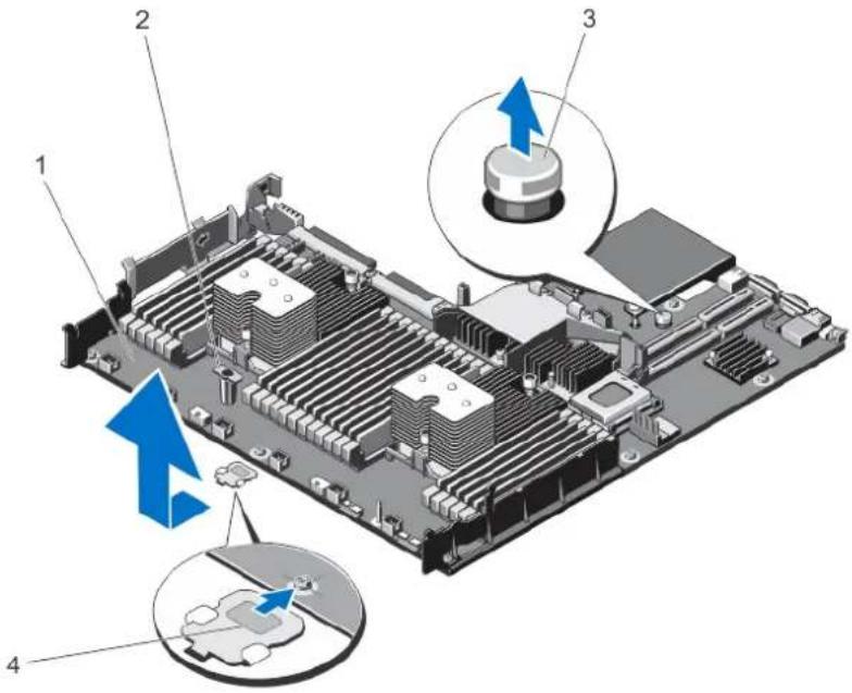
text_image
Diagram of a computer motherboard with numbered components and blue arrows indicating directional changes or features.Figure 77. Removing and Installing the System Board
1 system board 2 system-board holder
3 release pin 4 support bracket (present on certain systems only)
WARNING: The heat sink and processor are hot to the touch for some time after the system has been powered down. Allow the heat sink and processor to cool before handling them.
8 Remove heat sink(s)/heat-sink blank(s) and processors(s)/processor blank(s).
9 Remove memory modules and memory module blanks.
10 Remove network daughter card.
Installing The System Board

CAUTION: Many repairs may only be done by a certified service technician. You should only perform troubleshooting and simple repairs as authorized in your product documentation, or as directed by the online or telephone service and support team. Damage due to servicing that is not authorized by Dell is not covered by your warranty. Read and follow the safety instructions that came with the product.
1 Unpack the new system board assembly.
2 Transfer the following components to the new system board:
a heat sink(s)/heat-sink blank(s) and processors(s)/processor blank(s)
b memory modules and memory module blanks
c network daughter card
CAUTION: Do not lift the system board assembly by grasping a memory module, processor, or other components.
△| CAUTION: Take care not to damage the system identification button while placing the system board into the chassis.
3 Hold the touch points and lower the system board into the chassis.
4 Push the system board toward the back of the chassis until the board clicks into place.
5 Replace the following:
a cable retention bracket
b PCIe card holder
c integrated storage controller card
d internal USB key (if installed)
e internal dual SD module
f all expansion-card risers
g cooling-fan assembly
h cooling shroud
i power supply(s)
6 Reconnect all cables to the system board.
NOTE: Ensure that the cables inside the system are routed along the chassis wall and secured using the cable securing bracket.
7 Close the system.
8 Reconnect the system to its electrical outlet and turn the system on, including any attached peripherals.
9 Import your new or existing iDRAC Enterprise license. For more information, see iDRAC7 User's Guide, at dell.com/support/manuals.
Troubleshooting Your System
Safety First—For You And Your System

CAUTION: Many repairs may only be done by a certified service technician. You should only perform troubleshooting and simple repairs as authorized in your product documentation, or as directed by the online or telephone service and support team. Damage due to servicing that is not authorized by Dell is not covered by your warranty. Read and follow the safety instructions that came with the product.
Topics:
- Troubleshooting System Startup Failure
- Troubleshooting External Connections
- Troubleshooting The Video Subsystem
- Troubleshooting A USB Device
- Troubleshooting A Serial I/O Device
- Troubleshooting A NIC
- Troubleshooting A Wet System
- Troubleshooting A Damaged System
• Troubleshooting The System Battery - Troubleshooting Power Supplies
- Troubleshooting Cooling Problems
- Troubleshooting Cooling Fans
- Troubleshooting System Memory
- Troubleshooting An Internal USB Key
- Troubleshooting An SD Card
• Troubleshooting An Optical Drive - Troubleshooting A Tape Backup Unit
• Troubleshooting A Hard Drive - Troubleshooting A Storage Controller
- Troubleshooting Expansion Cards
- Troubleshooting Processors
Troubleshooting System Startup Failure
If you boot the system to the BIOS boot mode after installing an operating system from the UEFI Boot Manager, the system hangs. The reverse is also true. You must boot to the same boot mode in which you installed the operating system.
For all other startup issues, note the system messages that appear on the screen.
Troubleshooting External Connections
Ensure that all external cables are securely attached to the external connectors on your system before troubleshooting any external devices.
Troubleshooting The Video Subsystem
1 Check the system and power connections to the monitor.
2 Check the video interface cabling from the system to the monitor.
3 Run the appropriate diagnostic test.
If the tests run successfully, the problem is not related to video hardware.
If the tests fail, see Getting Help.
Troubleshooting A USB Device
Use the following steps to troubleshoot a USB keyboard/mouse. For other USB devices, go to step 7.
1 Disconnect the keyboard and mouse cables from the system briefly and reconnect them.
2 Connect the keyboard/mouse to the USB port(s) on the opposite side of the system.
3 If the problem is resolved, restart the system, enter the System Setup, and check if the non-functioning USB ports are enabled.
4 Replace the keyboard/mouse with another working keyboard/mouse.
5 If the problem is resolved, replace the faulty keyboard/mouse.
6 If the problem is not resolved, proceed to the next step to begin troubleshooting the other USB devices attached to the system.
7 Power down all attached USB devices and disconnect them from the system.
8 Reboot the system and, if your keyboard is functioning, enter the System Setup. Verify that all USB ports are enabled on the Integrated Devices screen, in the System Setup options.
If your keyboard is not functioning, you can also use remote access. If the system is not accessible, reset the NVRAM_CLR jumper inside your system and restore the BIOS to the default settings.
9 Reconnect and power on each USB device one at a time.
10 If a device causes the same problem, power down the device, replace the USB cable with a known good cable, and power up the device.
If all troubleshooting fails, see Getting Help.
Troubleshooting A Serial I/O Device
1 Turn off the system and any peripheral devices connected to the serial port.
2 Swap the serial interface cable with a working cable, and turn on the system and the serial device.
If the problem is resolved, replace the interface cable with a known good cable.
3 Turn off the system and the serial device, and swap the device with a comparable device.
4 Turn on the system and the serial device.
If the problem persists, see Getting Help.
Troubleshooting A NIC
1 Run the appropriate diagnostic test. See Using System Diagnostics for available diagnostic tests.
2 Reboot the system and check for any system messages pertaining to the NIC controller.
3 Check the appropriate indicator on the NIC connector:
- If the link indicator does not light, check all cable connections.
- If the activity indicator does not light, the network driver files might be damaged or missing. Remove and reinstall the drivers if applicable. See the NIC's documentation.
- If applicable, change the autonegotiation setting.
- Use another connector on the switch or hub.
4 Ensure that the appropriate drivers are installed and the protocols are bound. See the NIC's documentation.
5 Enter the System Setup and confirm that the NIC ports are enabled on the Integrated Devices screen.
6 Ensure that the NICs, hubs, and switches on the network are all set to the same data transmission speed and duplex. See the documentation for each network device.
7 Ensure that all network cables are of the proper type and do not exceed the maximum length.
If all troubleshooting fails, see Getting Help.
Troubleshooting A Wet System

CAUTION: Many repairs may only be done by a certified service technician. You should only perform troubleshooting and simple repairs as authorized in your product documentation, or as directed by the online or telephone service and support team. Damage due to servicing that is not authorized by Dell is not covered by your warranty. Read and follow the safety instructions that came with the product.
1 Turn off the system and attached peripherals, and disconnect the system from the electrical outlet.
2 Open the system.
3 Disassemble components from the system:
- Hard drives
- Hard-drive backplane
- USB memory key
- Cooling shroud
- Expansion-card risers (if present)
- Expansion cards
• Power supply(s)
• Cooling-fan assembly (if present) - Cooling fans
- Processor(s) and heat sink(s)
- Memory modules
4 Let the system dry thoroughly for at least 24 hours.
5 Reinstall the components you removed in step 3.
6 Close the system.
7 Turn on the system and attached peripherals.
If the system does not start properly, see Getting Help.
8 If the system starts properly, shut down the system and reinstall all of the expansion cards that you removed.
9 Run the appropriate diagnostic test. For more information, see Using System Diagnostics.
If the tests fail, see Getting Help.
Troubleshooting A Damaged System

CAUTION: Many repairs may only be done by a certified service technician. You should only perform troubleshooting and simple repairs as authorized in your product documentation, or as directed by the online or telephone service and support team. Damage due to servicing that is not authorized by Dell is not covered by your warranty. Read and follow the safety instructions that came with the product.
1 Turn off the system and attached peripherals, and disconnect the system from the electrical outlet.
2 Open the system.
3 Ensure that the following components are properly installed:
- Cooling shroud
- Expansion-card risers (if present)
- Expansion cards
- Power supply(s)
• Cooling-fan assembly (if present) - Cooling fans
- Processor(s) and heat sink(s)
- Memory modules
- Hard-drive carriers
- Hard-drive backplane
4 Ensure that all cables are properly connected.
5 Close the system.
6 Run the appropriate diagnostic test. For more information, see System Diagnostics.
If the tests fail, see Getting Help.
Troubleshooting The System Battery

CAUTION: Many repairs may only be done by a certified service technician. You should only perform troubleshooting and simple repairs as authorized in your product documentation, or as directed by the online or telephone service and support team. Damage due to servicing that is not authorized by Dell is not covered by your warranty. Read and follow the safety instructions that came with the product.

NOTE: If the system is turned off for long periods of time (for weeks or months), the NVRAM may lose its system configuration information. This situation is caused by a defective battery.
1 Re-enter the time and date in the System Setup.
2 Turn off the system and disconnect it from the electrical outlet for at least one hour.
3 Reconnect the system to the electrical outlet and turn on the system.
4 Enter the System Setup.
If the date and time are not correct in the System Setup, check the SEL for system battery messages.
If the problem persists, see Getting Help.

NOTE: Some software may cause the system time to speed up or slow down. If the system seems to operate normally except for the time kept in the System Setup, the problem may be caused by software rather than by a defective battery.
Troubleshooting Power Supplies

CAUTION: Many repairs may only be done by a certified service technician. You should only perform troubleshooting and simple repairs as authorized in your product documentation, or as directed by the online or telephone service and support team. Damage due to servicing that is not authorized by Dell is not covered by your warranty. Read and follow the safety instructions that came with the product.
Reseat the power supply by removing and reinstalling it.

NOTE: After installing a power supply, allow several seconds for the system to recognize the power supply and to determine if it is working properly.
If the problem persists, see Getting Help.
Troubleshooting Cooling Problems

CAUTION: Many repairs may only be done by a certified service technician. You should only perform troubleshooting and simple repairs as authorized in your product documentation, or as directed by the online or telephone service and support team. Damage due to servicing that is not authorized by Dell is not covered by your warranty. Read and follow the safety instructions that came with the product.
Ensure that none of the following conditions exist:
• System cover, cooling shroud, EMI filler panel, memory-module blank, or back-filler bracket is removed.
- Ambient temperature is too high.
- External airflow is obstructed.
- A cooling fan is removed or has failed.
- The expansion card installation guidelines have not been followed.
Troubleshooting Cooling Fans

CAUTION: Many repairs may only be done by a certified service technician. You should only perform troubleshooting and simple repairs as authorized in your product documentation, or as directed by the online or telephone service and support team. Damage due to servicing that is not authorized by Dell is not covered by your warranty. Read and follow the safety instructions that came with the product.
1 Open the system.
2 Reseat the fan or the fan's power cable.
3 If the fan functions properly, close the system.
If the problem persists, see Getting Help.
Troubleshooting System Memory

CAUTION: Many repairs may only be done by a certified service technician. You should only perform troubleshooting and simple repairs as authorized in your product documentation, or as directed by the online or telephone service and support team. Damage due to servicing that is not authorized by Dell is not covered by your warranty. Read and follow the safety instructions that came with the product.
1 If the system is operational, run the appropriate diagnostic test. See Using System Diagnostics for available diagnostic tests. If diagnostics indicates a fault, follow the corrective actions provided by the diagnostic program.
2 If the system is not operational, turn off the system and attached peripherals, and unplug the system from the power source. Wait at least 10 seconds and then reconnect the system to power.
3 Turn on the system and attached peripherals and note the messages on the screen.
If an error message is displayed indicating a fault with a specific memory module, go to step 12.
4 Enter the System Setup and check the system memory setting. Make any changes to the memory settings, if needed. If the memory settings match the installed memory but a problem is still indicated, go to step 12.
5 Turn off the system and attached peripherals, and disconnect the system from the electrical outlet.
6 Open the system.
7 Check the memory channels and ensure that they are populated correctly.
8 Reseat the memory modules in their sockets.
9 Close the system.
10 Enter the System Setup and check the system memory setting.
If the problem is not resolved, proceed with the next step.
11 Open the system.
12 If a diagnostic test or error message indicates a specific memory module as faulty, swap or replace the module with a known good memory module.
13 To troubleshoot an unspecified faulty memory module, replace the memory module in the first DIMM socket with a module of the same type and capacity.
If an error message is displayed on the screen, this may indicate a problem with the installed DIMM type(s), incorrect DIMM installation, or defective DIMM(s). Follow the on-screen instructions to resolve the problem. For more information, see General Memory Module Installation Guidelines.
14 Close the system.
15 As the system boots, observe any error message that is displayed and the diagnostic indicators on the front of the system.
16 If the memory problem is still indicated, repeat step 12 through step 15 for each memory module installed.
If the problem persists after all memory modules have been checked, see Getting Help.
Troubleshooting An Internal USB Key

CAUTION: Many repairs may only be done by a certified service technician. You should only perform troubleshooting and simple repairs as authorized in your product documentation, or as directed by the online or telephone service and support team. Damage due to servicing that is not authorized by Dell is not covered by your warranty. Read and follow the safety instructions that came with the product.
1 Enter the System Setup and ensure that the USB key port is enabled on the Integrated Devices screen.
2 Turn off the system and attached peripherals, and disconnect the system from the electrical outlet.
3 Open the system.
4 Locate the USB key and reseat it.
5 Close the system.
6 Turn on the system and attached peripherals and check if the USB key is functioning.
7 If the problem is not resolved, repeat step 2 and step 3.
8 Insert a different USB key that you know works properly.
9 Close the system.
If the problem is not resolved, see Getting Help.
Troubleshooting An SD Card

CAUTION: Many repairs may only be done by a certified service technician. You should only perform troubleshooting and simple repairs as authorized in your product documentation, or as directed by the online or telephone service and support team. Damage due to servicing that is not authorized by Dell is not covered by your warranty. Read and follow the safety instructions that came with the product.

NOTE: Certain SD cards have a physical write-protect switch on the card. If the write-protect switch is turned on then the SD card is not writeable.
1 Enter the System Setup and ensure that the Internal SD Card Port is enabled.
2 Turn off the system, including any attached peripherals, and disconnect the system from the electrical outlet.
3 Open the system.

CAUTION: If the Internal SD Card Redundancy option is set to Mirror Mode in the Integrated Devices screen of the System Setup, you must follow the instructions in step 4 through step 7 to avoid loss of data.
NOTE: When an SD card failure occurs, the internal dual SD module controller notifies the system. On the next reboot, the system displays a message indicating the failure.
4 If the Internal SD Card Redundancy option is set to Disabled, replace the failed SD card with a new SD card.
5 If SD card 1 has failed, remove the card from SD card slot 1. If SD card 2 has failed, install a new SD card in SD card slot 2 and proceed to step 7.
6 Remove the card present in SD card slot 2 and insert it into SD card slot 1.
7 Insert the new SD card into SD card slot 2.
8 Close the system.
9 Reconnect the system to its electrical outlet and turn the system on, including any attached peripherals.
10 Enter the System Setup and ensure that the Internal SD Card Port and Internal SD Card Redundancy mode is enabled.
11 Check if the SD card is functioning properly.
If the problem persists, see Getting Help.
Troubleshooting An Optical Drive
CAUTION: Many repairs may only be done by a certified service technician. You should only perform troubleshooting and simple repairs as authorized in your product documentation, or as directed by the online or telephone service and support team. Damage due to servicing that is not authorized by Dell is not covered by your warranty. Read and follow the safety instructions that came with the product.
1 Try using a different CD or DVD.
2 Enter the System Setup and ensure that the integrated SATA controller and the drive's SATA port are enabled.
3 Run the appropriate diagnostic test.
4 Turn off the system and attached peripherals, and disconnect the system from the electrical outlet.
5 Open the system.
6 Remove the front bezel.
7 Ensure that the interface cable is securely connected to the optical drive and to the controller.
8 Ensure that a power cable is properly connected to the drive.
9 Close the system.
If the problem is not resolved, see Getting Help.
Troubleshooting A Tape Backup Unit
CAUTION: Many repairs may only be done by a certified service technician. You should only perform troubleshooting and simple repairs as authorized in your product documentation, or as directed by the online or telephone service and support team. Damage due to servicing that is not authorized by Dell is not covered by your warranty. Read and follow the safety instructions that came with the product.
1 Try using a different tape cartridge.
2 Ensure that the device drivers for the tape backup unit are installed and are configured correctly. See your tape drive documentation for more information about device drivers.
3 Reinstall the tape-backup software as instructed in the tape-backup software documentation.
4 Ensure that the tape drive's interface cable is fully connected to the external port on the controller card.
5 Check that the controller card is properly installed:
a Turn off the system and attached peripherals, and disconnect the system from the electrical outlet.
b Open the system.
c Reseat the controller card in the expansion card slot.
d Close the system.
e Turn on the system and attached peripherals.
6 Run the appropriate diagnostic test. For more information, see Using System Diagnostics.
If you cannot resolve the problem, see Getting Help.
Troubleshooting A Hard Drive
CAUTION: Many repairs may only be done by a certified service technician. You should only perform troubleshooting and simple repairs as authorized in your product documentation, or as directed by the online or telephone service and support team. Damage due to servicing that is not authorized by Dell is not covered by your warranty. Read and follow the safety instructions that came with the product.
CAUTION: This troubleshooting procedure can erase data stored on the hard drive. Before you proceed, back up all files on the hard drive.
1 Run the appropriate diagnostic test. For more information, see Using System Diagnostics.
Depending on the results of the diagnostics test, proceed as needed through the following steps.
2 If your system has a RAID controller and your hard drives are configured in a RAID array, perform the following steps:
a Reboot the system and press
See the Lifecycle Controller documentation or online help for information on RAID configuration.
b Ensure that the hard drive(s) are configured correctly for the RAID array.
c Take the hard drive offline and reseat the drive.
d Exit the configuration utility and allow the system to boot to the operating system.
b Ensure that the hard drive(s) are configured correctly for the RAID array.
c Take the hard drive offline and reseat the drive.
d Exit the configuration utility and allow the system to boot to the operating system.
3 Ensure that the required device drivers for your controller card are installed and are configured correctly. See the operating system documentation for more information.
4 Reboot the system and enter the System Setup.
5 Verify that the controller is enabled and the drives are displayed in the System Setup.
If the problem persists, try troubleshooting the expansion cards or see Getting Help.
Troubleshooting A Storage Controller
CAUTION: Many repairs may only be done by a certified service technician. You should only perform troubleshooting and simple repairs as authorized in your product documentation, or as directed by the online or telephone service and support team. Damage due to servicing that is not authorized by Dell is not covered by your warranty. Read and follow the safety instructions that came with the product.
NOTE: When troubleshooting a SAS or PERC controller, see the documentation for your operating system and the controller.
1 Run the appropriate diagnostic test. For more information, see Using System Diagnostics.
2 Turn off the system and attached peripherals, and disconnect the system from the electrical outlet.
3 Open the system.
4 Verify that the installed expansion cards are compliant with the expansion card installation guidelines.
5 Ensure that each expansion card is firmly seated in its connector.
6 Close the system
7 Reconnect the system to the electrical outlet, and turn on the system and attached peripherals.
8 If the problem is not resolved, turn off the system and attached peripherals, and disconnect the system from the electrical outlet.
9 Open the system.
10 Remove all expansion cards installed in the system.
11 Close the system.
12 Reconnect the system to the electrical outlet, and turn on the system and attached peripherals.
13 Run the appropriate diagnostic test. For more information, see Using System Diagnostics. If the tests fail, see Getting Help.
14 For each expansion card you removed in step 10, perform the following steps:
a Turn off the system and attached peripherals, and disconnect the system from the electrical outlet.
b Open the system.
c Reinstall one of the expansion cards.
d Close the system.
e Run the appropriate diagnostic test. For more information, see Using System Diagnostics.
If the tests fail, see Getting Help.
Troubleshooting Expansion Cards
CAUTION: Many repairs may only be done by a certified service technician. You should only perform troubleshooting and simple repairs as authorized in your product documentation, or as directed by the online or telephone service and support team. Damage due to servicing that is not authorized by Dell is not covered by your warranty. Read and follow the safety instructions that came with the product.
NOTE: When troubleshooting an expansion card, see the documentation for your operating system and the expansion card.
1 Run the appropriate diagnostic test. For more information, see Using System Diagnostics.
2 Turn off the system and attached peripherals, and disconnect the system from the electrical outlet.
3 Open the system.
4 Ensure that each expansion card is firmly seated in its connector.
5 Close the system.
6 If the problem is not resolved, turn off the system and attached peripherals, and disconnect the system from the electrical outlet.
7 Open the system.
8 Remove all expansion cards installed in the system.
9 Close the system.
10 Run the appropriate diagnostic test. For more information, see Using System Diagnostics.
If the tests fail, see Getting Help.
11 For each expansion card you removed in step 8, perform the following steps:
a Turn off the system and attached peripherals, and disconnect the system from the electrical outlet.
b Open the system.
c Reinstall one of the expansion cards.
d Close the system.
e Run the appropriate diagnostic test. For more information, see Using System Diagnostics.
If the problem persists, see Getting Help.
Troubleshooting Processors
CAUTION: Many repairs may only be done by a certified service technician. You should only perform troubleshooting and simple repairs as authorized in your product documentation, or as directed by the online or telephone service and support team. Damage due to servicing that is not authorized by Dell is not covered by your warranty. Read and follow the safety instructions that came with the product.
1 Run the appropriate diagnostics test. See Using System Diagnostics for available diagnostic tests.
2 Turn off the system and attached peripherals, and disconnect the system from the electrical outlet.
3 Open the system.
4 Ensure that the processor and heat sink are properly installed.
5 Close the system.
6 Run the appropriate diagnostic test. For more information, see Using System Diagnostics.
If the problem persists, see Getting Help.
Using system diagnostics
If you experience a problem with your system, run the system diagnostics before contacting Dell for technical assistance. The purpose of running system diagnostics is to test your system hardware without using additional equipment or risking data loss. If you are unable to fix the problem yourself, service and support personnel can use the diagnostics results to help you solve the problem.

NOTE: For more information about OEM diagnostic event messages, see the Event and Error Message Reference Guide for 13th Generation Dell PowerEdge Servers Version 1.2
Topics:
- Dell Online Diagnostics
• Dell Embedded System Diagnostics
Dell Online Diagnostics
Dell Online Diagnostics, a stand-alone suite of diagnostic programs or test modules, allows you to run diagnostic tests on the systems in a production environment, and helps you ensure maximum uptime of your systems. Online Diagnostics allows you to run diagnostic tests on chassis and storage components such as hard drives, physical memory, and network interface cards (NICs). You can use the graphical user interface (GUI) or the command line interface (CLI) to run diagnostic tests on the hardware that Online Diagnostics discovers on your system. For information about using diagnostics, see the Dell Online PowerEdge Diagnostics User's Guide under Software > Serviceability Tools, at dell.com/support/manuals.
Dell Embedded System Diagnostics

NOTE: Also known as Enhanced Pre-boot System Assessment (ePSA) diagnostics.
The embedded system diagnostics provides a set of options for particular device groups or devices allowing you to:
- Run tests automatically or in an interactive mode
- Repeat tests
• Display or save test results - Run thorough tests to introduce additional test options to provide extra information about the failed device(s)
• View status messages that inform you if tests are completed successfully
• View error messages that inform you of problems encountered during testing
When To Use The Embedded System Diagnostics
If a major component or device in the system does not operate properly, running the embedded system diagnostics may indicate component failure.
Running The Embedded System Diagnostics
The embedded system diagnostics program is run from the Dell Lifecycle Controller.

CAUTION: Use the embedded system diagnostics to test only your system. Using this program with other systems may cause invalid results or error messages.
1 As the system boots, press
2 Use the up and down arrow keys to select System Utilities > Launch Dell Diagnostics.
The ePSA Pre-boot System Assessment window is displayed, listing all devices detected in the system. The diagnostics starts executing the tests on all the detected devices.
System Diagnostic Controls
Menu Description
Configuration
Displays the configuration and status information of all detected devices.
Results Displays the results of all tests that are executed.
System Health Provides the current overview of the system performance.
Event Log
Displays a time-stamped log of the results of all tests run on the system. This is displayed if at least one event description is recorded.
Jumpers And Connectors
Topics:
- System Board Jumper Settings
- System Board Connectors
• Disabling A Forgotten Password
System Board Jumper Settings
For information on resetting the password jumper to disable a password, see Disabling A Forgotten Password.
Table 5. System Board Jumper Settings
Jumper Setting Description
| PWRD_EN | (default) | The password feature is enabled (pins 4-6). |
| The password feature is disabled (pins 2-4). iDRAC local access is unlocked at the next AC power cycle. | ||
| NVRAM_CLR | (default) | The configuration settings are retained at system boot (pins 1-3). |
| The configuration settings are cleared at the next system boot (pins 3-5). |
System Board Connectors
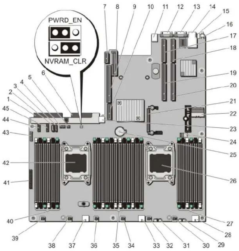
text_image
PWRD_EN NVRAM_CLRFigure 78. System Board Jumpers and Connectors
Item Connector Description
1 J_PS2 PSU 2 power connector
2 J_SATA_CD Optical drive SATA connector
3 J_SATA_TBU Tape backup unit SATA connector
4 J_BPO Optical drive power connector
5 J_TBU Tape backup unit power connector
6 J_PS1 PSU 1 power connector
7 J_IDSDM Internal dual SD module connector
8 J_NDC Network daughter card connector
9 J\_RISER\_3A Riser 3 connector
| 10 | J_RISER_3B | Riser 3 connector |
| 11 | J_USB USB connector | |
| 12 | J_VIDEO_REAR | Video connector |
| 13 | J_COM1 | Serial connector |
Item Connector Description
| 14 J_IDRAC_RJ45 iDRAC7 connector | ||
| 15 J_CYC System identification connector | ||
| 16 CYC_ID System identification button | ||
| 17 J_RISER_2A Riser 2 connector | ||
| 18 J_RISER_1A Riser 1 connector | ||
| 19 J_RISER_2B Riser 2 connector | ||
| 20 J_RISER_1B Riser 1 connector | ||
| 21 J_STORAGE Integrated storage controller card connector | ||
| 22 J_SASX8 | Mini SAS connector | |
| 23 J_USB_INT | Internal USB connector | |
| 24 J_SAS_PCH | SAS connector for software RAID | |
| 25 BAT | Battery connector | |
| 26 CPU2 | Processor socket 2 | |
| 27 | B10, B6, B2, B9, B5, B1 | Memory module sockets |
| 28 J_BP3 | Backplane power connector | |
| 29 J_BP_SIG3 | Backplane signal connector 3 | |
| 30 J_FAN2U_6 | Cooling fan connector | |
| 31 J_BP_SIG2 | Backplane signal connector 2 | |
| 32 J_FAN2U_5 | Cooling fan connector | |
| 33 J_BP2 Backplane power connector | ||
| 34 J_FAN2U_4 | Cooling fan connector | |
| 35 | A10, A6, A2, A9, A5, A1, B3, B7, B11, B4, B8, B12 | Memory module sockets |
| 36 J_FAN2U_3 | Cooling fan connector | |
| 37 | J_BP1 | Backplane power connector |
| 38 J_FAN2U_2 | Cooling fan connector | |
| 39 J_FAN2U_1 | Cooling fan connector | |
| 40 A3, A7, A11, A4, A8, A12 | Memory module sockets | |
| 41 J_CP | Control panel interface connector | |
| 42 CPU1 | Processor socket 1 | |
| 43 J_FP_USB | Front-panel USB connector | |
| 44 J_BP_SIG1 | Backplane signal connector 1 | |
| 45 J_BP_SIG0 | Backplane signal connector 0 | |
Disabling A Forgotten Password
The system's software security features include a system password and a setup password. The password jumper enables these password features or disables them and clears any password(s) currently in use.

CAUTION: Many repairs may only be done by a certified service technician. You should only perform troubleshooting and simple repairs as authorized in your product documentation, or as directed by the online or telephone service and support team. Damage due to servicing that is not authorized by Dell is not covered by your warranty. Read and follow the safety instructions that came with the product.
1 Turn off the system, including any attached peripherals, and disconnect the system from the electrical outlet.
2 Open the system.
3 Move the jumper on the system-board jumper from pins 4 and 6 to pins 2 and 4.
4 Close the system.
The existing passwords are not disabled (erased) until the system boots with the jumper on pins 2 and 4. However, before you assign a new system and/or setup password, you must move the jumper back to pins 4 and 6.

NOTE: If you assign a new system and/or setup password with the jumper on pins 2 and 4, the system disables the new password(s) the next time it boots.
5 Reconnect the system to its electrical outlet and turn the system on, including any attached peripherals.
6 Turn off the system, including any attached peripherals, and disconnect the system from the electrical outlet.
7 Open the system.
8 Move the jumper on the system-board jumper from pins 2 and 4 to pins 4 and 6.
9 Close the system.
10 Reconnect the system to its electrical outlet and turn the system on, including any attached peripherals.
11 Assign a new system and/or setup password.
Technical Specifications
NOTE: The following specifications apply to both PowerEdge R720 and PowerEdge R720xd unless specified otherwise.
Processor
Processor type One or two Intel Xeon processor E5-2600 or E5-2600v2 product family
Expansion Bus
Bus type PCI Express Generation 3
Expansion slots using riser card:
Riser 1 (Slot 1) One half-height, low-profile x8 link
(Slot 2) One half-height, low-profile x8 link
(Slot 3) One half-height, low-profile x8 link
Riser 2 (Slot 4) One full-height, full-length x16 link
NOTE: To use slots 1 through 4, both the processors must be installed.
(Slot 5) One full-height, full-length x8 link
Riser 3 (default) (Slot 6) One full-height, full-length x8 link (PowerEdge R720)
(Slot 7) One full-height, full-length x8 link (PowerEdge R720)
Riser 3 (alternate for GPU) (Slot 6) One full-height, full-length x16 link
Memory
Architecture 800 MT/s, 1066 MT/s, 1333 MT/s or 1600 MT/s, or 1866 MT/s
DDR3 registered, unbuffered or load-reduced Error Correcting Code (ECC) DIMMs
Support for advanced ECC or memory optimized operation
Memory module sockets Twenty-four 240-pin
Memory module capacities
LRDIMMs 32 GB quad-ranked or 64 GB octal-ranked
RDIMMs 2 GB, 4 GB, 8 GB, or 32 GB single-, dual-, or quad-ranked
16 GB single- or dual-ranked
UDIMMs 2 GB or 4 GB
Minimum RAM 2 GB with a single processor
4 GB with two processors
Maximum RAM
Memory
| LRDIMMs Up to 1536 GB (PowerEdge R720xd with 2.5 inch hard-drive configuration) | |
| RDIMMs Up to 512 GB | |
| UDIMMs Up to 64 GB | |
| Drives | |
| Hard drives(PowerEdge R720) | |
| Four-hard-drive systems | Up to four 3.5 inch, internal, hot-swappable SATA hard drives in hard-drive slots 0 through 3 (hard-drive slots 4 through 7 do not support any hard drives and are installed with a hard-drive blank). |
| NOTE: Four-hard-drive systems support software RAID. For more information on software RAID, see the Dell PowerEdge RAID Controller (PERC) documentation at support.dell.com/manuals. | |
| Eight-hard-drive systems Up to eight 3.5 inch or 2.5 inch, internal, hot-swappable SAS, SATA, orNearline SAS hard drives in hard-drive slots 0 through 7. | |
| Sixteen or eight plus eight-hard-drive systems Up to sixteen 2.5 inch, internal, hot-swappable SAS, SATA, SATA SSD,or Nearline SAS hard drives in hard-drive slots 0 through 15 or 0through 7 and 0 through 7. | |
| Twelve-hard-drive systems Up to eight 2.5 inch, internal, hot-swappable SAS, SATA, SATA SSD, orNearline SAS hard drives in hard-drive slots 0 through 7 (hard-drive bay 1) and up to four 2.5 inch Dell PowerEdge Express Flash devices (PCIe SSDs) in hard-drive slots 0 through 3 (hard-drive bay 2). | |
| Hard drives(PowerEdge R720xd) | |
| Twelve plus two-hard-drive systems Up to twelve 3.5 inch, internal, hot-swappable SAS, SATA, SATA SSD,or Nearline SAS drives, and two optional 2.5 inch back-accessible SAS,Nearline SAS, or SSD hard drives in hard-drive slots 0 through 11 and 12 through 13. | |
| Twenty-four plus two-hard-drive systems Up to twenty-four 2.5 inch, internal, hot-swappable SAS, SATA, SATASSD, or Nearline SAS drives in hard-drive slots 0 through 23 and twooptional 2.5 inch back-accessible SAS, Nearline SAS, or SSD harddrives in hard-drive slots 24 and 25. | |
| Optical drive(PowerEdge R720) | One optional SATA DVD-ROM drive or DVD+/-RW drive. |
| NOTE: DVD devices are data only. | |
Connectors
Back
NIC Four 10/100/1000 Mbps or two 10/100/1000 Mbps and two 100
Mbps/1 Gbps/10 Gbps
Serial 9-pin, DTE, 16550-compatible
Connectors
USB Two 4-pin, USB 2.0-compliant
Video 15-pin VGA
External vFlash card
(PowerEdge R720xd)
One flash memory card slot with iDRAC7 Enterprise card
NOTE: The card slot is available for use only if the iDRAC7 Enterprise license is installed on your system.
Front
USB Two 4-pin, USB 2.0-compliant (PowerEdge R720)
One 4-pin, USB 2.0-compliant (PowerEdge R720xd)
Video 15-pin VGA
External vFlash card
(PowerEdge R720)
One flash memory card slot with iDRAC7 Enterprise card
NOTE: The card slot is available for use only if the iDRAC7 Enterprise license is installed on your system.
Internal
USB One 4-pin, USB 2.0-compliant
Internal Dual SD Module Two optional flash memory card slots with the internal SD module
NOTE: One card slot is dedicated for redundancy.
Video
Video type Integrated Matrox G200
Video memory 16 MB shared
Expanded Operating Temperature
NOTE: When operating in the expanded temperature range, system performance may be impacted.
NOTE: When operating in the expanded temperature range, ambient temperature warnings may be reported on the LCD and in the System Event Log.
≤ 10% of annual operating hours 5 °C to 40 °C at 5% to 85% RH with 26 °C dew point.
NOTE: Outside the standard operating temperature (10 °C to 35 °C), the system can operate down to 5 °C or up to 40 °C for a maximum of 10% of its annual operating hours.
For temperatures between 35 °C and 40 °C, de-rate maximum allowable dry bulb temperature by 1 °C per 175 m above 950 m (1 °F per 319 ft).
≤ 1% of annual operating hours -5 °C to 45 °C at 5% to 90% RH with 26 °C dew point.
NOTE: Outside the standard operating temperature (10 °C to 35 °C), the system can operate down to -5 °C or up to 45 °C for a maximum of 1% of its annual operating hours.
Expanded Operating Temperature
| For temperatures between 40 °C and 45 °C, de-rate maximum allowable dry bulb temperature by 1 °C per 125 m above 950 m (1 °F per 228 ft). | |
| Expanded Operating Temperature Restrictions | Do not perform a cold startup below 5 °C.The operating temperature specified is for a maximum altitude of 3050 m (10,000 ft).130 W (4 core) processor is not supported.Redundant power supplies are required.Non Dell qualified peripheral cards and/or peripheral cards greater than 25 W are not supported. |
| NOTE: For PowerEdge R720, maximum 130 W processor is supported in either 8 hard drive or 16 hard drive chassis. | |
| NOTE: The following additional restrictions apply to PowerEdge R720xd.Maximum 95 W processor supported on 3.5 inch hard drive chassis.Maximum 115 W processor supported on 2.5 inch hard drive chassis.Only SSDs are allowed in the hard drive slots at the back of the 3.5 inch hard drive chassis. |
Environmental
NOTE: For additional information about environmental measurements for specific system configurations, see dell.com/environmental_datasheets.
Temperature
Maximum Temperature Gradient (Operating and Storage) 20 °C/h (36 °F/h)
Storage Temperature Limits -40^ to 65^ (-40°F to 149°F)
Temperature (Continuous Operation)
Temperature Ranges (for altitude less than 950 m or 3117 ft)
10 °C to 35 °C (50 °F to 95 °F) with no direct sunlight on the equipment.
NOTE: When using PowerEdge R720 with internal GPU card(s), the continuous operation range is 10 °C to 30 °C at 10% to 80% RH, with 26 °C max dew point.
Humidity Percentage Range 10% to 80% Relative Humidity with 26 °C (78.8 °F) maximum dew point.
Relative Humidity
Storage 5% to 95% RH with 33 °C (91 °F) maximum dew point.
Atmosphere must be non-condensing at all times.
Maximum Vibration
Operating 0.26 G
rms at 5 Hz to 350 Hz (all operation orientations).
Storage 1.87 G
rms at 10 Hz to 500 Hz for 15 min (all six sides tested).
Maximum Shock
Environmental
Operating One shock pulse in the positive z axis of 31 G for 2.6 ms in all
operational orientations.
Storage Six consecutively executed shock pulses in the positive and
negative x, y, and z axes (one pulse on each side of the system) of 71 G for up to 2 ms.
Maximum Altitude
Operating
3048 m (10,000 ft).
Storage 12,000 m (39,370 ft).
Operating Altitude De-rating
Up to 35 °C (95 °F) Maximum temperature is reduced by 1 °C/300 m (1 °F/547 ft)
above 950 m (3,117 ft).
35 °C to 40 °C (95 °F to 104 °F) Maximum temperature is reduced by 1 °C/175 m (1 °F/319 ft)
above 950 m (3,117 ft).
40 °C to 45 °C (104 °F to 113 °F) Maximum temperature is reduced by 1 °C/125 m (1 °F/228 ft)
above 950 m (3,117 ft).
Particulate Contamination
NOTE: This section defines the limits to help avoid IT equipment damage and/or failure from particulates and gaseous contamination. If it is determined that levels of particulates or gaseous pollution are beyond the limits specified below and are the reason for the damage and/or failures to your equipment, it may be necessary for you to re-mediate the environmental conditions that are causing the damage and/or failures. Re-mediation of environmental conditions will be the responsibility of the customer.
Air Filtration
NOTE: Applies to data center environments only. Air filtration requirements do not apply to IT equipment designed to be used outside a data center, in environments such as an office or factory floor.
Data center air filtration as defined by ISO Class 8 per ISO 14644-1 with a 95% upper confidence limit.
NOTE: Air entering the data center must have MERV11 or MERV13 filtration.
Conductive Dust
NOTE: Applies to data center and non-data center environments.
Air must be free of conductive dust, zinc whiskers, or other conductive particles.
Corrosive Dust
NOTE: Applies to data center and non-data center environments.
- Air must be free of corrosive dust.
- Residual dust present in the air must have a deliquescent point less than 60% relative humidity.
Gaseous Contamination
NOTE: Maximum corrosive contaminant levels measured at ≤50% relative humidity.
Copper Coupon Corrosion Rate <300 Å/month per Class G1 as defined by ANSI/ISA71.04-1985.
Silver Coupon Corrosion Rate <200 Å/month as defined by AHSRAE TC9.9.
System Messages
Topics:
- LCD Messages
- System Error Messages
- Warning Messages
- Diagnostic Messages
- Alert Messages
LCD Messages
NOTE: Applicable only if your system has an LCD display.
The LCD messages consist of brief text messages that refer to events recorded in the System Event Log (SEL). For information on the SEL and configuring system management settings, see the systems management software documentation.
NOTE: If your system fails to boot, press the System ID button for at least 5 seconds until an error code is displayed on the LCD. Record the code, then see System Error Messages.
Viewing LCD Messages
If a system error occurs, the LCD screen will turn amber. Press the Select button to view the list of errors or status messages. Use the Left and Right buttons to highlight an error number, and press the Select button to view the error.
Removing LCD Messages
For faults associated with sensors, such as temperature, voltage, fans, and so on, the LCD message is automatically removed when that sensor returns to a normal state. For other faults, you must take action to remove the message from the display:
- Clear the SEL — You can perform this task remotely, but you will lose the event history for the system.
- Power cycle — Turn off the system and disconnect it from the electrical outlet; wait approximately 10 seconds, reconnect the power cable, and restart the system.
System Error Messages
System messages appear on the monitor to notify you of a possible problem with the system. These messages refer to events recorded in the System Event Log (SEL). For information on the SEL and configuring system management settings, see the systems management software documentation.
Some messages are also displayed in an abbreviated form on the system's LCD, if the system includes that feature.
NOTE The LCD error messages listed here are displayed in the simple format. See Setup Menu to select the format in which the messages are displayed.
NOTE: If you receive a system message not listed here, check the documentation of the application that was running when the message was displayed or the operating system's documentation for an explanation of the message and recommended action.
NOTE: In some messages, a particular system component is identified by name (“
Error Code Message Information
| AMP0302 | Message | The system boardcurrent is greater than the upper warning threshold. |
| Details | System boardcurrent is outside of the optimum range. | |
| Action | 1 Review system power policy.2 Check system logs for power related failures.3 Review system configuration changes.4 If the issue persists, see Getting Help. | |
| AMP0303 | Message | The system boardcurrent is greater than the upper critical threshold. |
| LCD Message System boardcurrent is outside of range. | ||
| Details | System boardcurrent is outside of the optimum range. | |
| Action | 1 Review system power policy.2 Check system logs for power related failures.3 Review system configuration changes.4 If the issue persists, see Getting Help. | |
| ASR0000 | Message The watchdog timer expired. | |
| Details | The operating system or an application failed to communicate within the time-out period. | |
| Action Check the operating system, application, hardware, and system event log for exception events. | ||
| ASR0001 | Message The watchdog timer reset the system. | |
| Details The operating system or an application failed to communicate within the time-out period. The system was reset. | ||
| Action Check the operating system, application, hardware, and system event log for exception events. | ||
| ASR0002 | Message The watchdog timer powered off the system. | |
| Details The operating system or an application failed to communicate within the time-out period. The system was shut down. | ||
| Action Check the operating system, application, hardware, and system event log for exception events. | ||
| ASR0003 | Message The watchdog timer power cycled the system. | |
Error Code Message Information
| Details The operating system or an application failed to communicate within the time-out period. The system was power-cycled.Action Check the operating system, application, hardware, and system event log for exception events. | ||
| BAT0002 | Message The system board battery has failed.LCD Message The system board battery has failed. Check battery.Details The system board battery is either missing or bad.Action See Getting Help. | |
| BAT0017 | Message Thebattery has failed.LCD Message Thebattery has failed. Check battery.Details Thebattery is either missing, bad, or unable to charge due to thermal issues.Action Check system fans. If the problem persists, see Getting Help. | |
| CPU0000 | Message CPUhas an internal error (IERR).LCD Message CPUhas an internal error (IERR).Details System Event Log and Operating System Logs may indicate that the exception is external to the processor.Action Review System Event Log and Operating System Logs. If the issue persists, see Getting Help. | |
| CPU0001 | Message CPUhas a thermal trip (over-temperature) event.LCD Message CPUhas a thermal trip. Check CPU heat sink.Details The processor temperature increased beyond the operational range.Action Review the logs for fan failures. If no fan failures are detected, check inlet temperature (if available) and reinstall processor heat sink. If the problem persists, see Getting Help. | |
| CPU0005 | Message CPUconfiguration is unsupported.LCD Message CPUconfiguration is unsupported. Check CPU or BIOS revision.Details System is unable to boot or may run in a degraded state.Action Review the technical specifications for supported processor types. | |
| CPU0010 | Message CPUis throttled.Details The CPU is throttled due to thermal or power conditions.Action Review system logs for power or thermal exceptions. | |
| CPU0023 | Message CPUis absent. | |
Error Code Message Information
LCD Message CPU
Action Verify processor installation. If present, re-seat the processor.
CPU0204
Message CPU
LCD Message CPU
Details Voltages outside the allowable range may damage electrical components or may cause the system to shutdown.
Action
1 Turn off the system and remove input power for one minute.
2 Ensure the processor is seated correctly.
3 Reapply input power and turn on the system.
4 If the issue persists, see Getting Help.
CPU0700
Message CPU
LCD Message CPU
Details System BIOS was unable to initialize the processor.
Action
1 Turn off the system and remove input power for one minute.
2 Ensure the processor is seated correctly.
3 Reapply input power and turn on the system.
4 If the issue persists, see Getting Help.
CPU0701
Message CPU
LCD Message CPU
Details System event log and operating system logs may indicate that the exception is external to the processor.
Action
1 Check system and operating system logs for exceptions. If no exceptions are found, continue.
2 Turn off the system and remove input power for one minute.
3 Ensure the processor is seated correctly.
4 Reapply input power and turn on the system.
5 If the issue persists, see Getting Help.
CPU0702
Message CPU bus parity error detected.
LCD Message CPU bus parity error detected. Power cycle system.
Details System event log and operating system logs may indicate that the exception is external to the processor.
Action
1 Check system and operating system logs for exceptions. If no exceptions are found, continue.
Error Code Message Information
2 Turn off the system and remove input power for one minute.
3 Ensure the processor is seated correctly.
4 Reapply input power and turn on the system.
5 If the issue persists, see Getting Help.
CPU0703
Message CPU bus initialization error detected.
LCD Message CPU bus initialization error detected. Power cycle system.
Details System event log and operating system logs may indicate that the exception is external to the processor.
Action
1 Check system and operating system logs for exceptions. If no exceptions are found, continue.
2 Turn off the system and remove input power for one minute.
3 Ensure the processor is seated correctly.
4 Reapply input power and turn on the system.
5 If the issue persists, see Getting Help.
CPU0704
Message CPU
LCD Message CPU
Details System event log and operating system logs may indicate that the exception is external to the processor.
Action
1 Check system and operating system logs for exceptions. If no exceptions are found, continue.
2 Turn off the system and remove input power for one minute.
3 Ensure the processor is seated correctly.
4 Reapply input power and turn on the system.
5 If the issue persists, see Getting Help.
FAN0000
Message Fan
Details Fan operating speed is out of range.
Action Remove and reinstall the fan. If the issue persists, see Getting Help.
FAN0001
Message Fan
LCD Message Fan
Details Fan operating speed is out of range.
Action Remove and reinstall the fan. If the issue persists, see Getting Help.
FAN1201
Message Fan redundancy is lost.
LCD Message Fan redundancy is lost. Check fans.
Error Code Message Information
| Details Fan has failed.Action Remove and reinstall failed fans or install additional fans. | ||
| HWC1001 | Message Theis absent.LCD Message Theis absent. Check hardware.Details The absent device may be necessary for proper operation. System functionality may be degraded.Action Reinstall or reconnect the hardware. | |
| HWC2003 | MessageThe storagecable is not connected, or is improperly connected.LCD MessageStoragecable or interconnect failure. Check connection.Details The cable may be necessary for proper operation. System functionality may be degraded.Action Check if the cable is present, then reinstall or reconnect. | |
| HWC2005 | MessageThe system boardcable is not connected, or is improperly connected.LCD MessageSystem boardcable connection failure. Check connection.Details The cable may be necessary for proper operation. System functionality may be degraded.Action Check if the cable is present, then reinstall or reconnect. | |
| MEM0000 | Message Persistent correctable memory errors detected on a memory device at location(s).Details This is an early indicator of a possible future uncorrectable error.Action Re-seat the memory modules. If the issue persists, see Getting Help . | |
| MEM0001 | Message Multi-bit memory errors detected on a memory device at location(s).LCD MessageMulti-bit memory error on.Re-seat memory.Details The memory module has encountered an uncorrectable error. System performance may be degraded. The operating system and/or applications may fail as a result.Action Re-seat the memory modules. If the issue persists, see Getting Help. | |
| MEM0007 | Message Unsupported memory configuration; check memory device at location. LCD MessageUnsupported memory configuration. Check memory.Details The memory may not be seated correctly, misconfigured, or has failed. Memory size is reduced.Action Check the memory configuration. Re-seat the memory modules. If the issue persists, see Getting Help. | |
| MEM0701 | Message Correctable memory error rate exceeded for. | |
Error Code Message Information
| Details The memory may not be operational. This an early indicator of a possible futureuncorrectable error. | ||
| Action | Re-seat the memory modules. If the issue persists, see Getting Help. | |
| MEM0702 | Message Correctable memory error rate exceeded for. | |
| LCD Message | Correctable memory error rate exceeded for. Re-seat memory. | |
| Details The memory may not be operational. This an early indicator of a possible futureuncorrectable error. | ||
| Action | Re-seat the memory modules. If the issue persists, see Getting Help. | |
| MEM1205 | Message | Memory mirror redundancy is lost. Check memory device at location(s). |
| LCD Message | Memory mirror lost on. Power cycle system. | |
| Details | The memory may not be seated correctly, misconfigured, or has failed. | |
| Action | Check the memory configuration. Re-seat the memory modules. If the issue persists, seeGetting Help. | |
| MEM1208 | Message | Memory spare redundancy is lost. Check memory device at location. |
| LCD Message Memory spare lost on. Power cycle system. | ||
| Details Memory sparing is no longer available. | ||
| Action | Re-seat the memory modules. If the issue persists, see Getting Help. | |
| MEM8000 | Message | Correctable memory error logging disabled for a memory device at location. |
| LCD Message SBE log disabled on. Re-seat memory. | ||
| Details Errors are being corrected but no longer logged. | ||
| Action | Review system logs for memory exceptions. Reinstall memory at location. | |
| PCI1302 | Message | A bus time-out was detected on a component at busdevicefunction. |
| Details System performance may be degraded. The device has failed to respond to a transaction. | ||
| Action | Cycle input power, update component drivers, if device is removable, reinstall the device. | |
| PCI1304 | Message An I/O channel check error was detected. | |
| LCD Message I/O channel check error detected. Power cycle system. | ||
| Action | Cycle input power, update component drivers, if device is removable, reinstall the device. | |
| PCI1308 | Message | A PCI parity error was detected on a component at busdevicefunction. |
| LCD Message | PCI parity error on busdevicefunction. Power cycle system. | |
Error Code Message Information
| Details System performance may be degraded, PCI device may fail to operate, or system may fail to operate. | ||
| Action | Cycle input power, update component drivers, if device is removable, reinstall the device. | |
| PCI1320 | Message | A bus fatal error was detected on a component at busdevicefunction. |
| LCD Message | Bus fatal error on busdevicefunction.Power cycle system. | |
| Details System performance may be degraded, or system may fail to operate. | ||
| Action | Cycle input power, update component drivers, if device is removable, reinstall the device. | |
| PCI1342 | Message | A bus time-out was detected on a component at slot. |
| Details System performance may be degraded, or system may fail to operate. | ||
| Action | Cycle input power, update component drivers, if device is removable, reinstall the device. | |
| PCI1348 | Message | A PCI parity error was detected on a component at slot. |
| LCD Message PCI parity error on slot.Re-seat PCI card. | ||
| Details System performance may be degraded, or system may fail to operate. | ||
| Action | Cycle input power, update component drivers, if device is removable, reinstall the device. | |
| PCI1360 | Message | A bus fatal error was detected on a component at slot. |
| LCD Message Bus fatal error on slot.Re-seat PCI card. | ||
| Details System performance may be degraded, or system may fail to operate. | ||
| Action | Cycle input power, update component drivers, if device is removable, reinstall the device. | |
| PDR0001 | Message Fault detected on drive. | |
| LCD Message Fault detected on drive. Check drive. | ||
| Details | The controller detected a failure on the disk and has taken the disk offline. | |
| Action | Remove and re-seat the failed disk. If the issue persists, see Getting Help. | |
| PDR1016 | Message | Driveis removed from disk drive bay. |
| LCD Message | Driveremoved from disk drive bay. Check drive. | |
| Details The controller detected that the drive was removed. | ||
| Action | Verify drive installation. Re-seat the failed drive. If the issue persists, see Getting Help. | |
| PST0128 | Message No memory is detected. | |
| LCD Message No memory is detected. Inspect memory devices. | ||
| Details System BIOS was unable to detect memory in the system. | ||
Error Code Message Information
| Action | Re-seat the memory modules. If the issue persists, see Getting Help. | |
| PST0129 | Message Memory is detected, but is not configurable. | |
| LCD Message | Memory is detected, but is not configurable. Check memory devices. | |
| Details | System BIOS detected memory, but was unable to configure the memory for system operation. | |
| Action | Compare system memory installation to supported system memory configurations. | |
| PSU0001 | Message Power supplyfailed. | |
| LCD Message PSUfailed. Check PSU. | ||
| Action | Remove and reinstall the power supply. If the issue persists, see Getting Help. | |
| PSU0002 | Message A predictive failure detected on power supply. | |
| LCD Message Predictive failure on PSU. Check PSU. | ||
| Details System performance and power redundancy may be degraded or lost. | ||
| Action | Remove and reinstall the power supply at the next service window. If the issue persists, see Getting Help. | |
| PSU0003 | Message The power input for power supplyis lost. | |
| LCD Message | Power input for PSUis lost. Check PSU cables. | |
| Details The power supply is installed correctly but an input source is not connected or is not functional. | ||
| Action | Verify the input source is attached to the power supply. Verify the input power is within the operating requirements for the power supply. | |
| PSU0006 | Message Power supplytype mismatch. | |
| LCD Message | Power supplyis incorrectly configured. Check PSU. | |
| Details Power supplies should be of the same input type and power rating. | ||
| Action | Install matched power supplies and review proper configuration in this manual. | |
| PSU0016 | Message Power supplyis absent. | |
| LCD Message PSUis absent. Check PSU. | ||
| Details The power supply has been removed or has failed. | ||
| Action | 1 Remove and reinstall the power supply.2 Check cables and subsystem components in the system for damage.3 If the issue persists, see Getting Help. | |
Error Code Message Information
| PSU0031 | Message Cannot communicate with power supply. | |
| LCD Message Cannot communicate with PSU. Re-seat PSU. | ||
| Details The power supply may operate, however power supply monitoring is degraded. System performance may be degraded. | ||
| Action | Remove and reinstall the power supply. If the issue persists, see Getting Help. | |
| PSU0032 | Message | The temperature for power supplyis in a warning range. |
| Details System performance may be degraded. | ||
| Action | Check the system operating environment, including airflow and inlet temperature. Check system logs for temperature and thermal component failures. | |
| PSU0033 | Message | The temperature for power supplyis outside of the allowable range. |
| LCD Message | PSUtemperature outside of range. Check PSU. | |
| Details System performance may be degraded. | ||
| Action | Check the system operating environment, including airflow and inlet temperature. Check system logs for temperature and thermal component failures. | |
| PSU0034 | Message | An under voltage fault detected on power supply. |
| LCD Message | An under voltage fault detected on PSU. Check power source. | |
| Details | This failure may be the result of an electrical issue with cables or subsystem components in the system. | |
| Action | 1 Remove and reinstall the power supply.2 Check cables and subsystem components in the system for damage.3 If the issue persists, see Getting Help. | |
| PSU0035 | Message An over voltage fault detected on power supply. | |
| LCD Message Over voltage fault on PSU. Check PSU. | ||
| Action | Check input power or reinstall the power supply. If the issue persists, see Getting Help. | |
| PSU0036 | Message An over current fault detected on power supply. | |
| LCD Message | An over current fault detected on PSU. Check PSU. | |
| Details | This failure may be the result of an electrical issue with cables or subsystem components in the system. | |
| Action | 1 Remove and reinstall the power supply.2 Check cables and subsystem components in the system for damage.3 If the issue persists, see Getting Help. | |
Error Code Message Information
| PSU0037 | Message Fan failure detected on power supply. | |
| LCD Message Fan failure detected on PSU. Check PSU. | ||
| Action | Check for fan blockage. If the problem persists, see Getting Help. | |
| PSU0076 | Message | A power supply wattage mismatch is detected; power supplyis rated forwatts. |
| LCD Message | PSU wattage mismatch; PSU=watts | |
| Details Power supplies should be of the same input type and power rating. | ||
| Action | Install matched power supplies and review this manual for proper configuration. | |
| PSU1201 | Message Power supply redundancy is lost. | |
| Details The power supply tries to operate in a degraded state. System Performance and power redundancy may be degraded or lost. | ||
| Action | Check input power. Reinstall the power supply. If the issue persists, see Getting Help. | |
| PSU1204 | Message | The power supplies are not redundant. Insufficient resources to maintain normal operations. |
| LCD Message PSU redundancy degraded. Check PSU cables. | ||
| Details The current power operational mode is non-redundant because of a power supply exception, a power supply inventory change, or a system power inventory change. | ||
| Action | Check the event log for power supply failures. Review system configuration and power consumption. | |
| PWR1004 | Message The system performance degraded because power capacity has changed. | |
| Details The system may power down or operate in a performance degraded state. | ||
| Action | Check the event log for power supply failures. Review system configuration and power consumption and upgrade or install power supplies accordingly. | |
| PWR1005 | Message | The system performance degraded because the user-defined power capacity has changed. |
| Details | The user-defined power settings have affected system operation. | |
| Action | If unintended, review system configuration changes and power policy. | |
| PWR1006 | Message The system halted because system power exceeds capacity. | |
| LCD Message System power demand exceeds capacity. System halted. | ||
| Details The system halted because system power exceeds capacity. | ||
| Action | Review system configuration, upgrade power supplies or reduce system power consumption. | |
Error Code Message Information
| RFM1008 | Message Failure detected on Removable Flash Media. | |
| LCD Message Removable Flash Mediafailed. Check SD Card. | ||
| Details An error was reported during a SD card read or write. | ||
| Action | Reseat the flash media. If the problem persists, see Getting Help. | |
| RFM1014 | Message Removable Flash Mediais write protected. | |
| LCD Message | Removable Flash Mediais write protected. Check SD Card. | |
| Details | The card is write-protected by the physical latch on the SD card. A write-protected card cannot be used. | |
| Action If unintended, remove the media and disable write protection. | ||
| RFM1201 | Message Internal Dual SD Module redundancy is lost. | |
| LCD Message Internal Dual SD Module redundancy is lost. Check SD Card. | ||
| Details Either one or both the SD cards are not functioning properly. | ||
| Action See Getting Help. | ||
| RFM2001 | Message Internal Dual SD Moduleis absent. | |
| LCD Message | Internal Dual SD Moduleis absent. Check SD Card. | |
| Details The SD card module is not detected or not installed. | ||
| Action If unintended, reinstall the SD module. | ||
| RFM2002 | Message | Internal Dual SD Moduleis offline. |
| Details | The SD card module is installed but may be improperly installed or configured incorrectly. | |
| Action Reinstall the SD module. | ||
| RFM2004 | Message Failure detected on Internal Dual SD Module. | |
| LCD Message | Internal Dual SD Modulefailed. Check SD Card. | |
| Details | The SD card module is installed but improperly configured or failed to initialize. | |
| Action Reinstall the SD module and remove and reinstall SD cards. | ||
| RFM2006 | Message Internal Dual SD Moduleis write protected. | |
| Details The module is write-protected. Changes may not be written to the media. | ||
| Action If unintended, remove the media and disable write protection. | ||
| SEC0031 | Message The chassis is open while the power is on. | |
| LCD Message Intrusion detected. Check chassis cover. | ||
Error Code Message Information
Details The chassis is open. System performance may be degraded, and security may be compromised.
Action Close the chassis. Check system logs.
SEC0033
Message The chassis is open while the power is off.
LCD Message Intrusion detected. Check chassis cover.
Details The chassis was opened while the power was off. System security may have been compromised.
Action Close the chassis and verify hardware inventory. Check system logs.
SEL0006
Message All event logging is disabled.
Details This message is displayed when all event logging has been disabled by the user.
Action If unintended, re-enable logging.
SEL0008
Message Log is full.
Details When the event log is full, additional events are not written to the log. Older events may be overwritten and lost. This message may also appear if the user disabled event logging.
Action Backup and clear log.
SEL0012
Message Could not create or initialize the system event log.
Details If the system event log fails to initialize, platform status and failure events are not captured. Some management software do not report platform exceptions.
Action Reboot the management controller or iDRAC. Cycle system input power. If problem persists call support.
SEL1204
Message An unknown system hardware failure detected.
LCD Message Unknown system hardware failure.
Details If the system event log failed to initialize, platform status and failure events are not captured. Some management software do not report platform exceptions.
Action Re-configure system to the minimum supported configuration. If issues persist, contact support.
TMP0118
Message The system inlet temperature is less than the lower warning threshold.
LCD Message System inlet temperature is outside of range.
Details Ambient air temperature is too cool.
Action Check the system operating environment.
TMP0119
Message The system inlet temperature is less than the lower critical threshold.
LCD Message System inlet temperature is outside of range.
Error Code Message Information
Details Ambient air temperature is too cool.
Action Check the system operating environment.
TMP0120
Message The system inlet temperature is greater than the upper warning threshold.
LCD Message System inlet temperature is outside of range.
Details Ambient air temperature is too warm or one or more fans may have failed.
Action Check the system operating environment and review event log for fan failures.
TMP0121
Message The system inlet temperature is greater than the upper critical threshold.
LCD Message System inlet
Details Ambient air temperature is too warm or one or more fans may have failed.
Action Check the system operating environment and review event log for fan failures.
VLT0204
Message The system board
LCD Message System board voltage is outside of range.
Details System hardware detected an over voltage or under voltage condition.
If multiple voltage exceptions occur consecutively the system may power down in fail-safe mode.
Action
1 Review system logs for power supply exceptions.
2 Re-configure the system to minimum configuration, inspect and reinstall system cables.
3 If the issue persists, see Getting Help.
Warning Messages
A warning message alerts you to a possible problem and prompts you to respond before the system continues a task. For example, before you format a hard drive, a message warns you that you may lose all data on the hard drive. Warning messages usually interrupt the task and require you to respond by typing y (yes) or n (no).

NOTE Warning messages are generated by either the application or the operating system. For more information, see the documentation that accompanied the operating system or application.
Diagnostic Messages
The system diagnostic utilities may issue messages if you run diagnostic tests on your system. See the “Using System Diagnostics” chapter for more information about system diagnostics.
Alert Messages
Systems management software generates alert messages for your system. Alert messages include information, status, warning, and failure messages for drive, temperature, fan, and power conditions. For more information, see the systems management software documentation.
Getting Help
Contacting Dell
NOTE: If you do not have an active Internet connection, you can find contact information on your purchase invoice, packing slip, bill, or Dell product catalog.
Dell provides several online and telephone-based support and service options. Availability varies by country and product, and some services may not be available in your area. To contact Dell for sales, technical support, or customer service issues:
1 Visit dell.com/support
2 Select your support category.
3 Verify your country or region in the Choose a Country/Region drop-down menu at the top of page.
4 Select the appropriate service or support link based on your need.