7240XM - Régulateur Aruba - Free user manual and instructions
Find the device manual for free 7240XM Aruba in PDF.


| Product Type | Enterprise Wireless LAN Controller (Regulator) |
| Model | Aruba 7240XM |
| Dimensions (H x W x D) | 1.75 x 17.5 x 17.5 in (4.4 x 44.5 x 44.5 cm) |
| Weight (with one AC PSU) | 16.43 lbs (7.45 kg) |
| Power Supply Options | 350W AC (100-240 VAC, 2.5-5A, 50-60 Hz) or 350W DC (-36 to -72 VDC, 11A) |
| Maximum AP Support | 2048 Access Points |
| Memory | 16 GB SDRAM / 16 GB Flash |
| Minimum ArubaOS Release | 6.4.4 |
| Network Ports | 2 x Dual-Media (1000BASE-X SFP or 10/100/1000BASE-T RJ-45), 4 x 10GBASE-X SFP+ |
| Console Ports | 1 x RJ-45 Serial, 1 x Mini-USB (type B) |
| USB Interface | 1 x USB 2.0 |
| LCD Panel | 2-line, 16-character display with navigation buttons for status and basic operations |
| Fan Tray | Field-replaceable, hot-swappable with 4 fans; front-to-back airflow |
| Power Supply Redundancy | Supports load sharing and redundancy with two hot-swappable PSU slots |
| Mounting Options | Two-point 19-inch rack mount (included) or table/shelf installation |
| Operating Temperature | 0°C to 40°C (32°F to 104°F) |
| Operating Humidity | 5% to 95% non-condensing |
| Safety Compliance | FCC Part 15, CE, Industry Canada, RoHS (EU, India, China) |
| Spare Parts / Repairability | Hot-swappable fan tray and power supplies; field-replaceable SFPs; no user-serviceable internal parts |
| Maintenance | LCD menu for image upgrade, config upload/erase, factory reset, reboot; CLI management via console or SSH |
Frequently Asked Questions - 7240XM Aruba
User questions about 7240XM Aruba
0 question about this device. Answer the ones you know or ask your own.
Ask a new question about this device
Download the instructions for your Régulateur in PDF format for free! Find your manual 7240XM - Aruba and take your electronic device back in hand. On this page are published all the documents necessary for the use of your device. 7240XM by Aruba.
USER MANUAL 7240XM Aruba
Aruba 7200 Series Controller
aruba®
NETWORKS
an HP company
Copyright
© 2015 Aruba Networks, Inc. Aruba Networks trademarks include , Aruba Networks
®, Aruba
Wireless Networks ^® , the registered Aruba the Mobile Edge Company logo, Aruba Mobility Management System ^® , Mobile Edge Architecture ^® , People Move. Networks Must Follow ^® , RFProtect ^® , Green Island ^® . All rights reserved. All other trademarks are the property of their respective owners.
Open Source Code
Certain Aruba products include Open Source software code developed by third parties, including software code subject to the GNU General Public License (GPL), GNU Lesser General Public License (LGPL), or other Open Source Licenses. Includes software from Litech Systems Design. The IF-MAP client library copyright 2011 Infoblox, Inc. All rights reserved. This product includes software developed by Lars Fenneberg et al. The Open Source code used can be found at this site:
http://www.arubanetworks.com/open_source
Legal Notice
The use of Aruba Networks, Inc. switching platforms and software, by all individuals or corporations, to terminate other vendors' VPN client devices constitutes complete acceptance of liability by that individual or corporation for this action and indemnifies, in full, Aruba Networks, Inc. from any and all legal actions that might be taken against it with respect to infringement of copyright on behalf of those vendors.
Warranty
This hardware product is protected by an Aruba warranty. For details, see Aruba Networks standard warranty terms and conditions.

NETWORKS
an HP company
www.arubanetworks.com
1344 Crossman Avenue
Sunnyvale, California 94089
Phone: 408.227.4500
Fax 408.227.4550
Preface 5
Guide Overview....5
Related Documentation....5
Contacting Support 6
Chapter 1 7200 Controller....7
Models 7
Package Checklist 7
Front Panel 8
Dual-Media Ports 9
10/100/1000BASE-T (RJ-45) Ports....9
1000BASE-X (SFP) Ports....10
Dual-Media Port LEDs 10
10GBASE-X (SFP+) Ports 11
10GBASE-X Port LEDs....11
Power, Status, and Peered LEDs 12
LCD Panel....12
Disabling the LCD Screen 15
Mini USB Console Connector 15
Mini USB Driver 15
Console Port 16
Serial Console Port Adaptor 16
USB Interface....16
Expansion Slot....17
Rear Panel 17
Fan Tray....17
Hot Swapping 18
Power Supply 19
Load Sharing 19
Redundancy 19
Hot Swapping 19
Modules 19
AC Power Supply Overview....20
DC Power Supply Overview 21
Chapter 2 Installation 23
Precautions....23
Selecting a Location....24
Two-Point Rack Mounting....24
Required Tools and Equipment 24
Installation Steps 24
Table or Shelf Installation....26
Required Tools and Equipment 26
Installation Steps 26
Connecting the AC Power Cord 26
Installing and Removing a Fan Tray 26
Installing and Removing a Power Supply 28
Installing an AC Power Supply (PSU-350-AC)....28
Removing an AC Power Supply 29
Installing a DC Power Supply (PSU-350-DC) 29
Connecting DC Power to the Device....29
Removing a DC Power Supply 30
Installing an SFP 30
Removing an SFP 31
Connecting an LC Fiber Optic Cable 31
Chapter 3 Specifications, Safety, and Compliance 33
7200 Specifications....33
Physical 33
Power Supply Specifications....33
Operating Specifications 33
Storage Specifications 33
Safety and Regulatory Compliance 33
Regulatory Models....34
FCC 34
Industry Canada....34
Indonesia Compliance....34
EU Regulatory Conformance 34
Battery Statements 35
Proper Disposal of Aruba Equipment 35
Waste of Electrical and Electronic Equipment....35
European Union RoHS....35
India RoHS 35
China RoHS 36
This document describes the hardware features of the Aruba 7200 Series Controller. It provides a detailed overview of the physical and performance characteristics of each controller model and explains how to install the controller and its accessories.
Guide Overview
- Chapter 1, "7200 Controller" on page 7 provides a detailed hardware overview of the 7200 controller and each of its components.
- Chapter 2, "Installation" on page 23 describes how to install the 7200 in a number of ways and how to install each its components.
- Chapter 3, "Specifications, Safety, and Compliance" on page 33 lists the 7200's technical specifications and safety and regulatory compliance information.
Related Documentation
The latest ArubaOS User Guide and ArubaOS CLI Reference Guide are required for the complete management of an Aruba controller. The latest documentation and the translation of this document into other languages can be found at www.arubanetworks.com/documentation.
Contacting Support
Table 1 Contact Information
| Main Sitearubanetworks.com | |
| Support Sitesupport.arubanetworks.com | |
| Airheads Social Forums and KnowledgeBase | community.arubanetworks.com |
| North American Telephone 1-800-943-4526 (Toll Free)1-408-754-1200 | |
| International Telephones | http://www.arubanetworks.com/support-services/contact-support/ |
| Software Licensing Sitelicensing.arubanetworks.com | |
| End of Support information http://www.arubanetworks.com/support-services/end-of-life-products/end-of-life-policy/ | |
| Security Incident Response Team (SIRT) | http://www.arubanetworks.com/support-services/security-bulletins/ |
| Support Email Addresses | |
| Americas, APAC, and EMEAsupport@arubanetworks.com | |
| Security Incident Response Team (SIRT) sirt@arubanetworks.com | |
The Aruba 7200 Series of controllers consists of three enterprise-class, wireless LAN controllers. These controllers connect, control, and intelligently integrate wireless Access Points (APs) and Air Monitors (AMs) into a wired LAN system.
Models
The 7200 series includes three models that provide varying levels of functionality.
Table 2 Aruba 7200 Series Controller Models
| Model PSU | Number of APs Supported | SDRAM/ Flash | Minimum Supported Release | |
| 7210 350W AC 512 8 GB/ 8 GB ArubaOS 6.3 | ||||
| 7210DC 350W DC 512 8 GB/ 8 GB ArubaOS 6.3 | ||||
| 7220 350W AC 1024 8 GB/ 8 GB ArubaOS 6.3 | ||||
| 7220DC 350W DC 1024 8 GB/ 8 GB ArubaOS 6.3 | ||||
| 7240 350W AC 2048 8 GB/ 8 GB ArubaOS 6.3 | ||||
| 7240DC 350W DC 2048 8 GB/ 8 GB ArubaOS 6.3 | ||||
| 7240XM 350W AC 2048 16 GB/ 16GB ArubaOS 6.4.4 | ||||
| 7240XMDC 350W DC 2048 16 GB/ 16 GB ArubaOS 6.4.4 | ||||
Package Checklist
Inform your supplier if there are any incorrect, missing, or damaged parts. If possible, retain the carton, including the original packing materials (see Table 3). Use these materials to repack and return the unit to the supplier if needed.
Table 3 Package Contents
| Item | Quantity |
| Aruba 7200 Series Controller | 1 |
| Power Supply Unit - Installed | 1 |
| Fan Tray - Installed | 1 |
| Expansion Slot Cover - Installed | 1 |
| Blank Panel over unpopulated PSU Intake - Installed | 1 |
| Item Quantity | |
| Rack Mounting Brackets 2 | |
| M6 x 15 mm Rack Mounting Screws 4 | |
| M4 x 8mm Rack Mount Bracket Screws 8 | |
| M6 x 7 mm Grounding Screws 2 | |
| USB Console Cable 1 | |
| Power Cable 1 | |
| Aruba 7200 Series Installation Guide (Printed) (This document) 1 | |
| Quick Start guide (Printed) 1 | |
| End User License Agreement (Printed) 1 |

Optional accessories are available for use with the Aruba 7200 Series and are sold separately. Contact your Aruba sales representative for details and assistance.
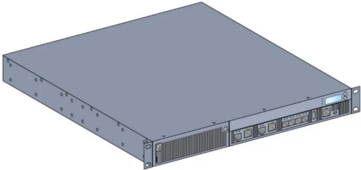
Front Panel
The front panel of the Aruba 7200 mobility controller contains the following components:
• Four 10GBASE-X (SFP+) ports
- Two Dual-Media Ports
• LINK/ACT and Status LEDs
• Power, Status, and Peered LEDs
• LCD Panel and Navigation Buttons
- USB Port
• Console Connections - RJ-45 and Mini-USB
• Expansion Slot (reserved for future use)
Figure 1 Front Panel of the 7200
natural_image
3D rendering of a server rack unit with ports and ventilation slots (no visible text or labels)Dual-Media Ports
The 7200 is equipped with 2 sets of dual-media ports (ports 0 and 1). These ports can utilize either the 1000BASE-X or 10/100/1000BASE-T connections provided. However, the 1000BASE-X fiber connection has priority over the 10/100/1000BASE-T copper connection. If a link is detected on the 1000BASE-X interface, the 10/100/1000BASE-T connection will be disabled.

Aruba tests and supports Aruba optics within their controller systems. Third party optics are not tested or supported; therefore, Aruba does not guarantee proper functionality of third party optics when used in an Aruba system.
10/100/1000BASE-T (RJ-45) Ports
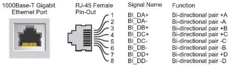
The 7200 controller is equipped with two 10/100/1000BASE-T copper ports as a part of dual media ports. Gigabit Ethernet uses all eight wires and each pair is used in a bi-directional fashion, meaning the same pairs are used for both data transmission and reception. Figure 2 illustrates the CAT-5 pin-out found on an RJ-45 connector. The CAT-5 pin-out pairs the following pins on a 10/100/1000BASE-T Gigabit Ethernet port: 1/2, 3/6, 4/5, and 7/8.
Figure 2 10/100/1000BASE-T Management Port Pin Out
text_image
1000Base-T Gigabit Ethernet Port RJ-45 Female Pin-Out Signal Name Function 1 BI_DA+ 2 BI_DA- 3 BI_DB+ 4 BI_DC+ 5 BI_DC- 6 BI_DB- 7 BI_DD+ 8 BI_DD- Function Bi-directional pair +A Bi-directional pair -A Bi-directional pair +B Bi-directional pair +C Bi-directional pair -C Bi-directional pair -B Bi-directional pair +D Bi-directional pair -D1000BASE-X (SFP) Ports
The 7200 is equipped with two 1000BASE-X combination ports for fiber connectivity only and are intended for use with Aruba SFPs (mini-GBICs).

Aruba tests and supports Aruba optics within their controller systems. Third party optics are not tested or supported; therefore, Aruba does not guarantee proper functionality of third party optics when used in an Aruba system.
Dual-Media Port LEDs
Each pair of Dual-Media ports is equipped two LEDs that allow you to monitor the status of and activity on the port. These LEDs provide basic monitoring of the status, activity, and basic configuration of each port. The STATUS LED behavior can be changed using LCD.
- LINK/ACT: on the left side of the port, displays the link status of the port.
- STATUS: on the right side of the port, displays the status of the port. The information displayed by this LED changes based on LCD's mode.
The LED behavior for each mode is described in Table 4 and Table 5.
Table 4 10/100/1000BASE-T Port LEDs
| LED | Function | LCD Mode | Indicator | Status |
| LINK/ACT Link status N/A Green (Solid) Link has been established | ||||
| Green (Blinking) Port is transmitting or receiving data | ||||
| Off No link | ||||
| STATUS | Port status | Administrative | Green (Solid) | Port Enabled |
| Off Port Administratively Disabled | ||||
| Duplex | Green (Solid) Full-duplex | |||
| Off Half-duplex | ||||
| Speed | Green (Solid) 1000 Mbps | |||
| Off 10/100 Mbps | ||||
Table 5 1000BASE-X Port LEDs
| LED | Function | LCD Mode | Indicator | Status |
| LINK/ACT Link status N/A Green (Solid) Link has been established | ||||
| Green (Blinking) Port is transmitting or receiving data | ||||
| Off No link | ||||
| STATUS | Port status | Administrative | Green (Solid) | Port Enabled |
| Off Port Administratively Disabled | ||||
| Duplex | Green (Solid) Full-duplex | |||
| Off NA | ||||
| Speed | Green (Solid) 1 Gbps | |||
| Off Speed mismatch | ||||
10GBASE-X (SFP+) Ports
The 7200 is equipped with four 10GBASE-X (SFP+) ports. These port are labeled as 2, 3, 4, and 5. These ports are intended for use with Aruba supported SFPs. SFPs are 10Gb hot-swappable, optical transceivers, which convert serial electrical signals to external serial optical or electrical signals. The ports support dual speed (1GbE or 10GbE) operation.

Aruba tests and supports Aruba optics within their controller systems. Third party optics are not tested or supported; therefore, Aruba does not guarantee proper functionality of third party optics when used in an Aruba system.
10GBASE-X Port LEDs
Each 10GBASE-X port is equipped two LEDs that allow you to monitor the status of and activity on the port. These LEDs provide basic monitoring of the status, activity, and basic configuration of each port. The STATUS LED behaviour can be changed using LCD.
- LINK/ACT: on the left side of the port, displays the link status of the port.
- Status: on the right side of the port, displays the status of the port. The information displayed by this LED changes based on LCD's mode. The LED behavior for each mode is described in Table 6.
Table 6 10GBASE-X Port LEDs
| LED | Function | LCD Mode | Indicator | Status |
| LINK/ACT | Link status | N/A | Green (Solid) | Link has been established |
| Green (Blinking) | Port is transmitting or receiving data | |||
| Off | No link | |||
| Status Port status Administrative Green (Solid) Port Enabled | ||||
| Off Port Administratively Disabled | ||||
| Duplex Green (Solid) Full-duplex | ||||
| Off NA | ||||
| Speed Green (Solid) 10 Gbps | ||||
| Off 1 Gbps | ||||
Power, Status, and Peered LEDs
In addition to the LEDs on each individual port, there are three additional LEDs on the front panel that provide overall status of the device. These LEDs provide basic monitoring of the overall status of the 7200 controller.
Table 7 Power, Status, and Peered LEDs
| LED Function Indicator Status | |||
| Power Input power status/system status | Green (Solid) Power On | ||
| Off | Power Off | ||
| Status | Module status | Green (Solid) Operational | |
| Amber (Solid) | Critical Alarm | ||
| Off | No power | ||
| Peered | Reserved for future use | N/A | N/A |
LCD Panel
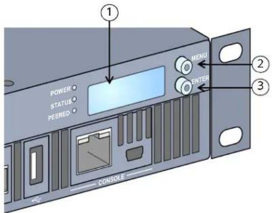
The 7200 is equipped with an LCD panel that displays a variety of information about the controller's status and provides a menu that allows for basic operations such as initial setup and reboot. The LCD panel displays two lines of text with a maximum of 16 characters on each line. When using the LCD panel, the active line is indicated by an arrow next to the first letter.
Figure 3 LCD Panel
text_image
POWER STATUS PEERED MENU ENTER 1 2 3 CONSOLETable 8 LCD Panel Components
| Callout Component Description | |
| 1 LCD Screen Used to configure LED behavior and other basic operations | |
| 2 Menu Button Used to select the LCD screen menu | |
| 3 Enter Button Used to execute actions on the LCD Screen | |
The LCD panel is operated using the two navigation buttons to the left of the screen.
- Menu: Allows you to navigate through the menus of the LCD panel.
- Enter: Confirms and executes the action currently displayed on the LCD panel.
The LCD has four modes:
- Boot: Displays the boot up status.
• LED Mode: Displays the mode that the STATUS LED is in. - Status: Displays the status of different components of the 7200, including Power Supplies and ArubaOS version.
- Maintenance: Allows you to execute some basic operations of the 7200 such as uploading an image or rebooting the system.
Table 9 LCD Panel Mode: Boot
| Function/Menu Options | Displays |
| Displays boot status “Booting ArubaOS... | |
The LED mode menu allows you to choose what information is communicated by the LEDs on each port. Refer to Table 6 on page 11 for descriptions of the LED behavior of each mode.
Table 10 LCD Panel Mode: LED Menu
| Function/Menu Options | Displays |
| Administrative LED MODE: ADM - displays whether the port is administratively enabled or disabled. | |
| Duplex LED MODE: DPX - displays the duplex mode of the port. | |
| Speed LED MODE: SPD - displays the speed of the port. | |
| Exit LED Menu EXIT LED MENU | |
Table 11 LCD Panel Mode: Status
| Function/Menu Options | Displays |
| ArubaOS Version ArubaOS X.X.X.X | |
| PSU Status Displays status of the power supply unit.PSU 0: [OK | FAILED | MISSING]PSU 1: [OK | FAILED | MISSING] | |
| Fan Tray Displays fan tray status.FAN STATUS: [OK | ERROR | MISSING]FAN TEMP: [OK | HIGH | SHUTDOWN] | |
| Exit Status Menu EXIT STATUS | |
Table 12 LCD Panel Mode: Maintenance
| Function/Menu Options | Displays |
| Upgrade Image | Upgrade the software image on the selected partition from a predefined location on the attached USB flash device.Partition [0 | 1] Upgrade Image [no | yes] |
| Upload Config Uploads the controller's current configuration to a predefined location on the attached USB flash device.Upload Config [no | yes] | |
| Erase Config Allows you to erase the current configuration.Erase Config [no | yes] | |
| Factory Default | Allows you to return the controller to the factory default settings.Factory Default [no | yes] |
| Media Eject | Completes the reading or writing of the attached USB device.Media Eject [no | yes] |
Table 12 LCD Panel Mode: Maintenance
| Function/Menu Options | Displays |
| System Reboot Allows you to reboot the controller. Reboot [no | yes] | |
| System Halt Allows you to halt the controller. Halt [no | yes] | |
| Exit Maintenance Menu EXIT MAINTENANCE | |
Disabling the LCD Screen
By default, the LCD screen is enabled. However, if your 7200 is deployed in a location without physical security, the LCD screen can be disabled through the CLI. When disabled, pushing one of the navigation buttons will only illuminate the screen and display the slot, role, device name, and any alarms.
Additionally, it is possible to only disable the maintenance menu. This allows you to change the LED behavior and view the device status but prevents upgrades and configuration changes.
To disable the LCD screen, enter the Enable mode and use the following CLI commands:
(host) #configure terminal
(host) (config) #lcd-menu
(host) (lcd-menu) #disable menu
To disable only the Maintenance menu or one of its sub-menus, enter the Enable mode and use the following CLI commands:
(host) #configure terminal
(host) (config) #lcd
(host) (lcd-menu) #disable menu maintenance ?
factory-default
halt-system
media-eject
reload-system
upgrade-image
upload-config
(host) (lcd-menu) #disable menu maintenance upgrade-image ?
partition0
partition1
Mini USB Console Connector
The 7200 is equipped with one Mini USB (mini type B) connector that provides console access for direct local access. If you are connected using the Mini USB connector and the RJ-45 Console Port, the Mini USB connection will take priority.
Mini USB Driver
To use the Mini USB console port, you must install the Aruba Mini USB driver on the computer that will manage your 7200. To download the driver:
- Go to https://support.arubanetworks.com.
- Click on the Tools & Resources tab.
- Open the USB Console Driver folder.
-
Open the Mobility Controller and Mobility Access Switch folder.
-
Select the file appropriate to your application. The corresponding operating system is in the file name.
Console Port
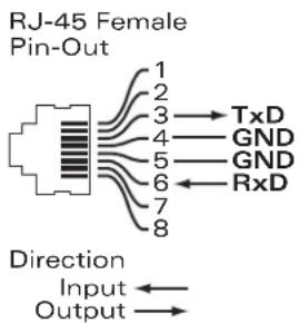
A serial console port is provided for connection to a terminal, allowing for direct local management. The port's RJ-45 female connector accepts an RS-232 serial cable with a male connector.
Figure 4 Serial Console Port Pin-Out
Serial
Console Port

text_image
RJ-45 Female Pin-Out 1 2 3 → TxD 4 — GND 5 — GND 6 ← RxD 7 8 Direction Input ← Output →Communication settings for the serial console port are indicated in Table 13.
Table 13 Console Terminal Settings
| Baud Rate | Data Bits | Parity | Stop Bits | Flow Control |
| 9600 8 None 1 None |

The CONSOLE port is compatible only with RS-232 devices. Non-RS-232 devices, such as APs, are not supported.

Do not connect the Console port to an Ethernet switch or a PoE power source. This may damage the controller.
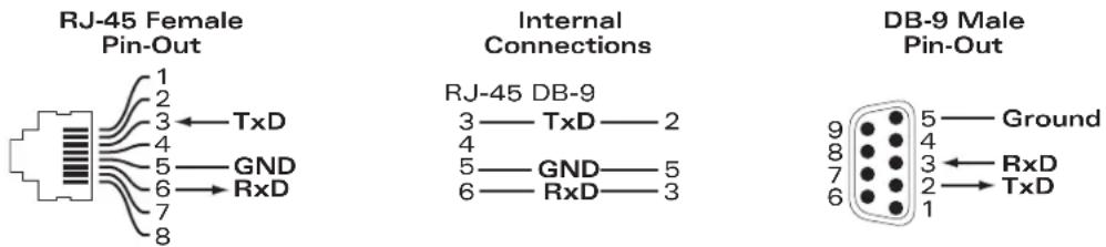
Serial Console Port Adaptor
A modular adaptor can be used to convert the RJ-45 (female) connector to a DB9 (male) connector. Refer to Figure 5 for complete details.
Figure 5 RJ-45 (female) to DB9 (male) Modular Adaptor Conversion
text_image
RJ-45 Female Pin-Out 1 2 3 ← TxD 4 5 — GND 6 → RxD 7 8 Internal Connections RJ-45 DB-9 3 — TxD — 2 4 5 — GND — 5 6 — RxD — 3 DB-9 Male Pin-Out 9 5 — Ground 8 4 7 ← RxD 6 2 → TxDUSB Interface
The 7200 is equipped with one USB 2.0 interface. A USB storage device can be used to save and upload configurations to the controller. USB functions are controlled through the LCD panel on the front of the controller. For more information on the LCD panel and its functions, see "LCD Panel" on page 12.
Expansion Slot
The expansion slot is reserved for future use.
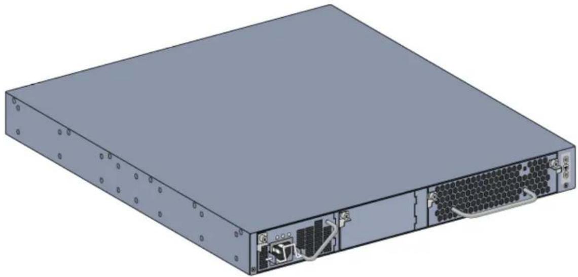
Rear Panel
The rear panel of the Aruba 7200 controller consists of the following components:
• Two power supply slots
• One fan tray slot
- Grounding point
Figure 6 Rear Panel
natural_image
3D rendering of a server rack with ventilation slots and ports (no text or symbols visible)Fan Tray
The 7200 is equipped with a field-replaceable, hot-swappable fan tray. Each fan tray features four individual fans that pull air through the chassis from the front through to the rear. Each fan tray can tolerate the failure of a single fan while maintaining a safe operating temperature for the controller.

The 7200 is not compatible with fan trays from other Aruba hardware platforms.
Hot Swapping
Hot swapping allows you to replace a failed fan tray, making it unnecessary to shut down the 7200 during the replacement procedure.
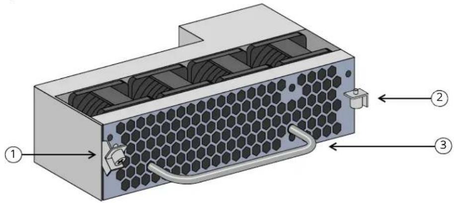
Figure 7 Fan Tray
text_image
Technical diagram of a hexagonal heat exchanger with labeled components and directional arrows indicating flow or movement.Table 14 Fan Tray Components
| Callout Component Description | |
| 1 Left Latch Used to secure the left side of the fan tray to the chassis. | |
| 2 Right Latch Used to secure the right side of the fan tray to the chassis. | |
| 3 Handle Used to insert and remove the fan tray from the chassis. | |
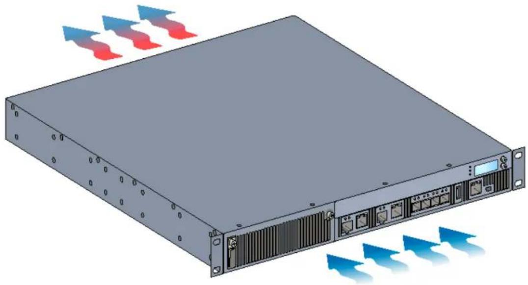
Figure 8 shows the airflow pattern for the 7200. The blue arrows show cool air being pulled into the device and the red arrows show warm air being forced out by the fan tray module. When installing your 7200, ensure that you leave sufficient space around the device for proper airflow.
Figure 8 Air Flow Pattern
natural_image
Illustration of a server rack with multiple ports and heat exchangers, emitting blue arrows (no text or symbols)Power Supply
Never insert or remove a power supply while the power cord is connected. Verify that cord has been disconnected from the power supply before installation or removal.
The Aruba 7200-series Power Supply adapts electrical power for use with the 7200. The chassis has two slots that can hold individual power supplies to support load sharing, redundancy, and fault tolerance. Two power supplies are available for use with 7200:
• 350W AC power supply
• 350W DC power supply
The Aruba 7200 is shipped with one hot-swappable, field-replaceable, AC power supply (DC power supply in 7200DC models) and one blank face plate. The included power supply is installed in the slot PSU 0, while slot PSU 1 has a blank face plate covering the opening. The controller can operate with one or two active power supplies, depending on the demands of your configuration.
Load Sharing
Load sharing occurs when more than one power supply of the same rating is installed in the 7200 and turned on. Load sharing divides the total power load of the controller among all available power supplies. Since the power supplies work together, the effective power capacity of the controller is increased with each additional power supply.
Redundancy
With power redundancy, the 7200 can continue normal operation even when a power supply fails or is turned off. When multiple power supplies are installed, if one becomes unavailable (fails, or is turned off or removed) the remaining power supplies will attempt to provide full power for the device. If the device's total power load does not exceed the combined rated output of the remaining, operational power supplies, the controller will continue to operate.
Hot Swapping
Hot swapping allows you to replace one failed power supply while the others provide full power. This makes it unnecessary to shut down the 7200 during the replacement procedure.
Hot swapping is supported only when power redundancy is in effect. This requires that after the target power supply is removed, the device's total power load does not exceed the combined rated output of the remaining power supplies
Modules
The 350W power supply is an autosensing, load-sharing, redundant power supply module that supports an input voltage of 100 VAC to 240 VAC (for AC) or -36 VDC to -72 VDC (for DC). Each power supply has a country-specific power cord for connection to an AC power outlet.
AC Power Supply Overview
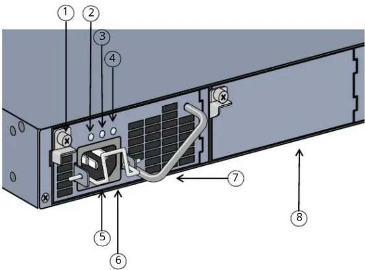
Figure 9 AC Power Supply
text_image
Diagram of a server rack with numbered components and labeled connectorsTable 15 AC Power Supply Components
| Callout Component Description | ||
| 1 Latch Used to secure the power supply to the chassis. | ||
| 2 AC LED AC status LED. | ||
| 3 DC LED DC status LED. | ||
| 4 TEMP LED Power supply temperature LED. | ||
| 5 Retaining Clip Secures the power cord to the power supply. | ||
| 6 AC Power Cable Socket Attach power cord here. | ||
| 7 Handle Used to insert and remove the power supply from the chassis. | ||
| 8 | P ow e Plate | Covers the extra power supply slot. Do not operate your 7200 without this blanking plate or a power supply in either slot. |
Each power supply is equipped with three LEDs to help monitor the power supply module's status.
Table 16 AC Power Supply Module LEDs
| LED | Description | Indicator | Status |
| AC | AC Status | Green (Solid) | Operating Normally. AC voltage is OK. |
| Red (Solid) | Power Supply Failure | ||
| DC | DC Status | Green (Solid) | Operating Normally |
| Red (Solid) | Power Supply Failure | ||
| TEMP Power Supply Temperature Green | (Solid) Operating | Normally | |
| Red (Solid) Temperature Alarm in PSU | |||
DC Power Supply Overview
Figure 10 DC Power Supply

text_image
PSU-350-DC 1 2 3 4 DC N DC OUT TEMP +VE -VE GND 6 5Table 17 DC Power Supply Components
| Callout Component Description | ||
| 1 Latch Used to secure the power supply to the chassis. | ||
| 2 DC IN LED DC input status LED. | ||
| 3 DC OUT LED DC output status LED. | ||
| 4 TEMP LED | Power supply temperature LED. | |
| 5 Handle | Used to insert and remove the power supply from the chassis. | |
| 6 Terminal Block | DC power cable connection points. | |
Each power supply is equipped with three LEDs to help monitor the power supply module's status.
Table 18 DC Power Supply Module LEDs
| LED | Description | Indicator | Status |
| DC IN | DC Input Status | Green (Solid) | Operating Normally |
| Red (Solid) | Power Supply Failure | ||
| LED Description Indicator Status | |||
| DC OUT DC Output Status Green (Solid) Operating Normally | |||
| Red (Solid) Power Supply Failure | |||
| TEMP Power Supply Temperature Green (Solid) Operating Normally | |||
| Red (Solid) Temperature Alarm in PSU | |||

Installation of the device should be performed by a trained installation professional.
This chapter describes how to install an Aruba 7200 controller using the many mounting options available. The 7200 ships with an accessory kit that includes the equipment needed to install the controller in standard, two-point 19-inch telco rack. Additional mounting options are sold separately.
• "Precautions" on page 23
• "Selecting a Location" on page 24
• "Two-Point Rack Mounting" on page 24
• "Table or Shelf Installation" on page 26
• "Connecting the AC Power Cord" on page 26
• "Installing and Removing a Fan Tray" on page 27
• "Installing and Removing a Power Supply" on page 29
Please only use included or Aruba specified cables, power cords, AC power supplies and batteries. The power cord should not be used with other electric equipment than what is specified by Aruba.

- Ensure that the rack is correctly and securely installed to prevent from falling or becoming unstable.
- Dangerous voltage in excess of 240VAC is always present while the Power Supply Module is plugged into an electrical outlet. Remove all rings, jewelry, and other potentially conductive material before working with this product.
- Never insert foreign objects into the chassis, the power supply, or any other component, even when the power supplies have been turned off, unplugged, or removed.
- Main power is fully disconnected from the 7200 by unplugging all installed power supplies' power cords from their outlets. For safety, verify the power outlets and plugs are in easy reach of the operator.
- Do not handle electrical cables which are not insulated. This includes any network cables.
• To minimize electrical hazard, keep water and other fluids away from the product. -
Comply with electrical grounding standards during all phases of installation and operation of the product. Do not allow the 7200 chassis, network ports, power supplies, or mounting brackets to contact any device, cable, object, or person attached to a different electrical ground. Also, never connect the device to external storm grounding sources.
-
Installation or removal of the chassis or any module must be performed in a static-free environment. The proper use of anti-static body straps and mats is strongly recommended.
- Modules must be kept in anti-static packaging when not installed in the chassis.
- Do not ship/store this product near strong electro-magnetic, electrostatic, magnetic or radioactive fields.
- Do not disassemble the chassis or any module.
Selecting a Location
The 7200, like other network and computing devices, requires an “electronics friendly” environment.
- Reliable power. Verify that your electrical outlet is compatible with the 7200 power supplies.
• Cool, non-condensing ventilation
For proper operation, the 7200 requires an environment with an ambient air temperature between 0 and 40 °C (32 to 104 °F). Humidity must be kept at non-condensing levels between 5 and 95%.
Where a large number of electrical devices are working in the same area, additional air conditioning or air circulation equipment may be required.
- Ample space
For proper air circulation, leave at least 10 cm (4 inches) clearance for the vents on the left, right, front, and rear of the chassis.
Leave additional space in front of the chassis to access power cords, network cables, and indicator LEDs.
• Limited electromagnetic interference
For best operation, keep the 7200 and all cords and cables at least 0.7 meters (2 feet) from fluorescent lighting fixtures, and 2 meters (6 feet) from photocopiers, radio transmitters, electric generators, and other sources of strong electromagnetic interference.
Two-Point Rack Mounting
The included two-point rack mounting kit provides the necessary hardware to securely mount an 7200 in standard 19" telco rack.

Each 7200 should have its own mounting equipment. Do not place other networking equipment directly on top a mounted 7200. Failure to do so can result in damage to the device.
Required Tools and Equipment
The following tools and equipment are required for installation of an Aruba 7200 controller:
- Rack mount bracket (2x, not used for tabletop installation)
- M4 x 8mm Phillips flat head screws (8x, included with rack mount brackets)
• M6 x 15mm Phillips pan head screws (4x, 19-inch (48.26 cm) rack system mount screws) - Suitable screwdrivers for both screw types

Some racks require screws that differ from those included with the 7200. Confirm that you have the correct screws before installing your 7200.
Installation Steps
To install an Aruba 7200 controller into a two-point 19-inch (48.26 cm) rack system:
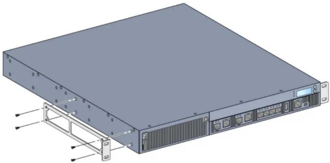
- Place a rack mount bracket over the mounting holes on one side of the controller (see Figure 11).
- Secure the bracket to the controller using four M4 x 8mm phillips flat head screws and a suitable screwdriver.
- Repeat these steps on the opposite side of the controller.
Figure 11 Rack Mount Brackets
natural_image
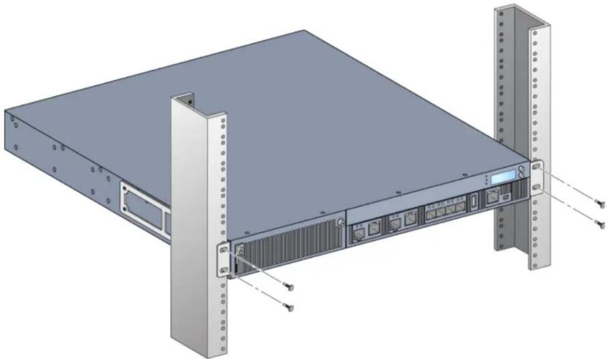
Illustration of a server rack unit with attached hardware components and mounting brackets (no text or symbols visible)- Mount the controller within your organization's rack system using four (two per bracket) M6 x 15mm Phillips pan head screws and suitable screwdriver (see Figure 12).
Figure 12 Rack Mount Installation
natural_image
3D rendering of a server rack unit with attached hardware components and mounting brackets (no text or symbols visible)-
Leave a minimum of four inches (10cm) of space on the left and right side of the unit for proper air flow and ventilation. See Figure 8 on page 18 for more information about the 7200's airflow requirements.
-
Leave additional space in front and back of the unit to access power cords, network cables, the LCD panel, and LED status indicators
Table or Shelf Installation
Required Tools and Equipment
• Rubber Feet (included)
Installation Steps
- Attach the included rubber feet to the bottom of the controller.
- Place your controller in the location you have chosen.
- Connect the AC power cord to the rear of the unit.
- Plug the opposite end of the power cord into an electrical outlet to power the controller.
Connecting the AC Power Cord
Once you have installed the 7200, you are ready to power on the device. The 7200 is not equipped with an On/Off switch. The device will turn on when the AC power cord has been connected to the power supply module and an AC power outlet.
To connect the AC power cord:
- Ensure that the power supply module is correctly installed in the 7200.
- Lift the power cord retaining clip so it is not blocking the AC power connector.
- Insert the coupler end of the AC power cord into the AC power connector on the power supply module.
- Lower the power cord retaining clip over the AC power cord.
The 7200 should now be receiving power. Since the 7200 does not have an On/Off switch, you must use the power cord to turn the device on or off. To turn the device off:
- Lift the power cord retaining clip off the AC power cord.
- Pull the AC power cord from the power supply module.
Installing and Removing a Fan Tray

Use standard ESD precautions when installing or removing a fan tray module.
The fan tray is field-replaceable and hot-swappable. Hot-swapping allows you to replace the fan tray without having to power down the 7200.
- Remove the old fan tray.
a. Using a Phillips Head screwdriver, turn the hinged captive screws counter-clockwise until loose (they cannot be removed completely).
b. Firmly grasp both of the hinged captive screws and pull the spring loaded hinge down until you are sure the hinges are disengaged. Use the fan tray handle to pull the fan out.
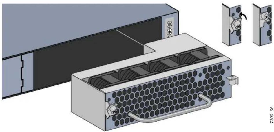
- Align the new fan tray module with opening in the controller, as shown in Figure 13.

Ensure that fan tray module is correctly aligned with the opening on the 7200. Failure to do so can result in damage to the fan tray module.
- Pull down the hinged captive screws on the new fan tray module and align its tabs with the slots on either side of the opening.
- Slide the fan tray module into the controller.
- Lift both the hinged captive screws into the lock position then secure the fan tray module by tightening the captive screws.
Figure 13 Installing a Fan Tray
natural_image
Illustration of a server rack with hexagonal mesh insulation and connected ports (no text or symbols)Installing and Removing a Power Supply

Never insert or remove a power supply while the power cord is connected. Verify that cord has been disconnected from the power supply before installation or removal.

Use standard ESD precautions when installing or removing a power supply module.
The power supply modules are hot-swappable. Hot swapping allows you to replace a failed power supply without powering down the 7200 during the replacement process. This makes it unnecessary to shut down the 7200 during the replacement procedure.
Installing an AC Power Supply (PSU-350-AC)

If you are adding an additional power supply module, removing the pre-installed power supply module blanking plate. If you are replacing a failed power supply, see "Removing an AC Power Supply" on page 30 before you continue.
- With a Phillips Head screwdriver, turn the hinged captive screw counter-clockwise until it is loose (they cannot be completely removed).
- Firmly grasp both of the hinged captive screws and pull the spring loaded hinge down until you are sure the hinges are disengaged.
- Grasp the power supply blanking plate by the hinged captive screw and slide the plate out.
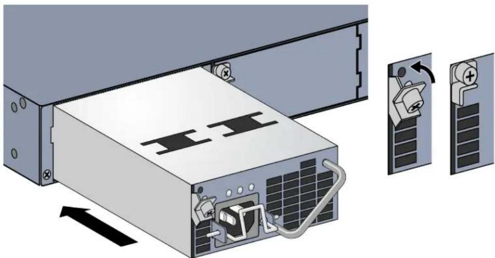
- Align the new power supply module with opening in the controller, as shown in Figure 14.
- Pull down the hinged captive screw on the power supply module and align its tab with the slot on the left side of the opening.
- Slide the power supply module into the controller.
- Lift the hinged captive screw and secure the power supply module by tightening the screw with a Phillips Head screwdriver. Take care not to over-tighten the screw.
Figure 14 Installing a Power Supply
natural_image
Diagram of a server rack with internal components and two labeled panels showing device states (no text or symbols present)- Insert the power cord and secure it by lowering the power cord retaining clip over the power cord.
Removing an AC Power Supply
To remove a power supply from your 7200:
- Lift the power cord retaining clip from the power cord.
- Remove the power cable connected to the power supply module.
-
Using a Phillips head screwdriver, loosen the hinged captive screw on the front of the power supply module.
-
Lower the hinged captive screw as far as it can go.
-
Using the power supply module's handle, pull the module out.
-
If you are not replacing the removed power supply module, install a blanking plate that was include with your 7200 by following the installation procedure under "Installing an AC Power Supply (PSU-350-AC)" on page 29.
Installing a DC Power Supply (PSU-350-DC)
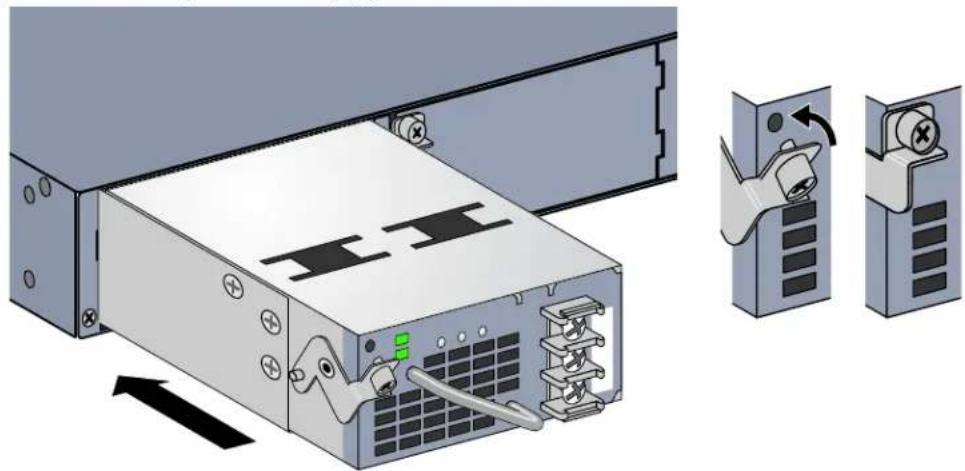
- Slide the power supply module into the controller.
- Lift the hinged captive screw and secure the power supply module by tightening the screw with a Phillips Head screwdriver. Take care not to over-tighten the screw.
Figure 15 Installing a Power Supply
natural_image
Diagram of a server rack with an open rear panel and two inset views showing a device's internal components (no text or symbols present)Connecting DC Power to the Device
To connect power to your PSU-350-DC:
- Ensure that the power supply is fully inserted and secure in the device.
- Ensure that the input circuit breaker is open and the voltage across the power source cables is 0V. This prevents the leads from becoming active while you connect the PSU to power.
- Remove the plastic terminal cover from the terminal.
- Remove the screws from the terminals using a Phillips-head screwdriver and save the screws.
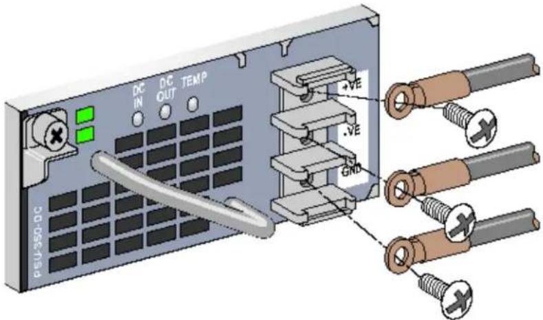
- To connect the power cables to the PSU-350-DC:
a. Secure the ring lug of the ground (GND) DC power source cable to the GND terminal on the PSU-350-DC.
b. Secure the ring lug of the positive (+) DC power source cable to the +VE terminal on the PSU-350-DC.
c. Secure the ring lug of the negative (-) DC power source cable to the -VE terminal on the PSU-350-DC.
d. Tighten each screw on the PSU-350-DC terminals until snug using a Phillips-head screwdriver.
Figure 16 Connecting Power Cables
text_image
DC IN DC OUT TEMP PEU-350-DC +VE -VE GND- Replace the plastic terminal block cover.
- Close the input circuit breaker.
- Verify that the LEDs on the power supply are lit green and steady.
Removing a DC Power Supply
To remove a DC power supply from your 7200:
- Ensure that the input circuit breaker is open and the voltage across the power source cables is 0V. This prevents the leads from becoming active while you connect the PSU to power.
- Remove the plastic terminal cover from the terminal.
- Remove the screws from the terminals using a Phillips-head screwdriver and save the screws.
- Remove the power cables connected to the power supply module.
- Using a Phillips head screwdriver, secure the terminal block screws.
- Reattach the plastic terminal cover.
- Using a Phillips head screwdriver, loosen the hinged captive screw on the front of the power supply module.
- Lower the hinged captive screw as far as it can go.
- Using the power supply module's handle, pull the module out.
- If you are not replacing the removed power supply module, install a blanking plate that was include with your 7200 by following the installation procedure under "Installing an AC Power Supply (PSU-350-AC)" on page 29.
Installing an SFP

Use standard ESD precautions when installing or removing an SFP.
To install an SFP module into the 7200:
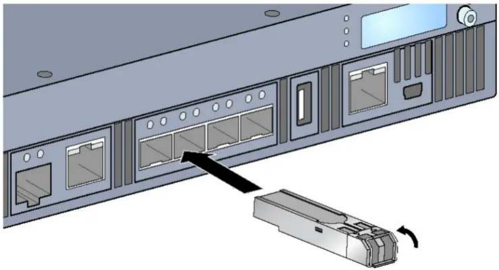
- Slide the SFP module, top side facing upward, into a 1000BASE-X port until a connection is made and an audible click is heard. See Figure 17 for more information.
Figure 17 Installing an SFP
natural_image
Diagram of a server rack with internal ports and a device casing, showing no text or symbolsRemoving an SFP
To remove an SFP module:
- Open and release the latch on the SFP module.
- Pull and remove the module from the port.
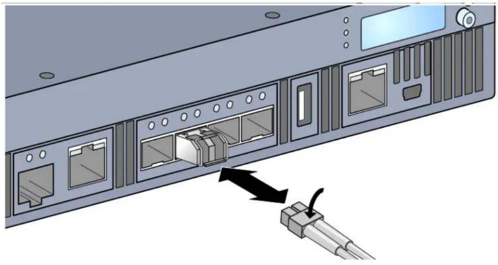
Connecting an LC Fiber Optic Cable
To connect an LC fiber optic cable into an SFP module:
- Clean the fiber optic cable connector before inserting it into the SFP module.
- Insert the fiber optic cable into the SFP module. Ensure that the latch on the cable faces the top of the SFP module.
- Slide the cable into place until a connection is made and an audible click is heard.
To disconnect an LC fiber optic cable from an SFP module:
- Depress the transceiver handle to release the latch on the cable and simultaneously pull the cable out of the port.
Figure 18 Connecting an LC Fiber Optic Cable
natural_image
Illustration of a server rack with internal ports and an attached cable connector (no text or symbols)7200 Specifications
Physical
• Device Dimensions (without mounting brackets) (HxWxD)
All Models: 1.75" x 17.5" x 17.5"
■ All Models: 4.4cm x 44.5cm x 44.5cm
• Device Weight (with one AC power supply installed)
■ All Models: 16.43 lbs (7.45 kg)
Power Supply Specifications
• 350W AC Power Supply
■ AC Input Voltage: 100 VAC to 240 VAC
■ AC Input Current: 2.5A to 5A
■ AC Input Frequency: 50 Hz to 60 Hz
■ Weight: 2.8 lbs (1.3 kg)
• 350W DC Power Supply
■ DC Input Voltage: -36 VDC to -72 VDC
■ DC Input Current: 11A
■ Weight: 3.2 lbs (1.44 kg)
Operating Specifications
- Operating Temperature Range: 0°C to 40°C (32°F to 104°F)
• Operating Humidity Range: 5% to 95% (RH), non-condensing
Storage Specifications
• Storage Temperature Range: 0°C to 50°C (32°F to 122°F)
• Storage Humidity Range: 5% to 95% (RH), non-condensing
Safety and Regulatory Compliance
Aruba Networks, Inc. provides a multi-language document that contains country-specific restrictions and additional safety and regulatory information for all Aruba products. This document can be viewed or downloaded from the following location: www.arubanetworks.com/safety_addendum

Aruba controllers must be installed by a professional installer. The professional installer is responsible for ensuring that grounding is available and it meets applicable local and national electrical codes.
Regulatory Models
This document covers the following models:
Table 19 Regulatory Model Numbers
| Part Number Regulatory Model Number | |
| 7210, 7210-IL, 7210-US, 7210DC, 7210DC-US, and 7210DC-IL ARCN0100 | |
| 7220, 7220-IL, 7220-US, 7220DC, 7220DC-IL, and 7220DC-US ARCN0101 | |
| 7240, 7240-IL, 7240-US, 7240DC, 7240DC-IL, 7240DC-US, 7240XM, 7240XMDC | ARCN0102 |
FCC
This device complies with Part 15 of the FCC Rules. Operation is subject to the following two conditions: (1) this device may not cause harmful interference, and (2) this device must accept any interference received, including interference that may cause undesired operation."
Industry Canada
EU Regulatory Conformance
This product is CE marked according to the provisions of the EMC Directive (2004/108/EC) - CE. Aruba Networks Inc., hereby declares that 7210; 7220 & 7240 device models are in compliance with the essential requirements and other relevant provisions of Directive (2004/108/EC). CE The Declaration of Conformity made under Directive 1999/5/EC is available for viewing at the following location in the EU community.
text_image
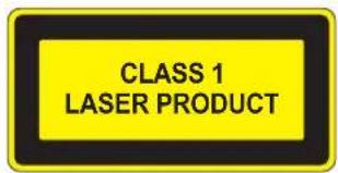
CLASS 1 LASER PRODUCT
Use of controls or adjustments of performance or procedures other than those specified in this manual may result in hazardous radiation exposure.
This product complies with 21 CFR Chapter 1, Subchapter J, Part 1040.10, and IEC 60825-1: 1993, A1: 1997, A2: 2001, IEC 60825-2: 2000.
For continued compliance with the above laser safety standards, only approved Class 1 modules from our approved vendors should be installed in the product.

Although this controller has been tested to up to 1kV per CE immunity requirements, this product requires surge protection to be provided as part of the building installation to protect against unidirectional surges resulting from electrical switching and lightning strikes. For protection against these surges in an outdoor installation, any exposed wiring must be shielded, and the shield for the wiring must be grounded at both ends.
Battery Statements

The battery supplied with this product may contain perchlorate material. Special handling may apply in California and other certain states. See www.dtsc.ca.gov/hazardouswaste/perchlorate for more information.

Risk of explosion if battery is replaced by an incorrect type. Dispose of used batteries according to the instructions.
Proper Disposal of Aruba Equipment
Waste of Electrical and Electronic Equipment

Aruba products at end of life are subject to separate collection and treatment in the EU Member States, Norway, and Switzerland and therefore are marked with the symbol shown at the left (crossed-out wheelie bin). The treatment applied at end of life of these products in these countries shall comply with the applicable national laws of countries implementing Directive 2002/96EC on Waste of Electrical and Electronic Equipment (WEEE).
European Union RoHS
RoHS
Aruba products also comply with the EU Restriction of Hazardous Substances Directive 2002/95/EC (RoHS). EU RoHS restricts the use of specific hazardous materials in the manufacture of electrical and electronic equipment. Specifically,
restricted materials under the RoHS Directive are Lead (including Solder used in printed circuit assemblies), Cadmium, Mercury, Hexavalent Chromium, and Bromine. Some Aruba products are subject to the exemptions listed in RoHS Directive Annex 7 (Lead in solder used in printed circuit assemblies). Products and packaging will be marked with the "RoHS" label shown at the left indicating conformance to this Directive.
India RoHS
This product complies with RoHS requirements as prescribed by E-Waste (Management & Handling) Rules, governed by the Ministry of Environment & Forests, Government of India.
China RoHS

Aruba products also comply with China environmental declaration requirements and are labeled with the "EFUP 50" label shown at the left.
有毒有害物 声明质
Hazardous Materials Declaration
| 部件名称(Parts) | 有毒有害物质或元素(Hazardous Substances) | |||||
| 铅Lead(Pb) | 汞Mercury(Hg) | 镉Cadmium(Cd) | 六价铬Chromium VI Compounds( Cr^6+ ) | 多溴联苯Polybrominated Biphenyls(PBB) | 多溴二苯醚Polybrominated Diphenyl Ether(PBDE) | |
| 电路板PCA Board | X | O | O | O | O | O |
| 机械组件Mechanical Subassembly | X | O | O | O | O | O |
| 电源适配器Power Adaptor | X | O | O | O | O | O |
| O:表示该有毒有害物质在该部件还有均质材料中的含量均在SJ/T11363-2006标准规定的限量要以下。This component does not contain this hazardous substance above the maximum concentration values in homogeneous materials specified in the SJ/T11363-2006 Industry Standard. | ||||||
| X:表示该有毒有害物质至少在该部件的某一均质材料中的含量超出SJ/T11363-2006标准规定的限量要。This component does contain this hazardous substance above the maximum concentration values in homogeneous materials specified in the SJ/T11363-2006 Industry Standard. | ||||||
| 对销售之目的所售产品,本表显示,供应链的电子信息产品可能包含这些物质。This table shows where these substances may be found in the supply chain of electronic information products, as of the date of sale of the enclosed product. | ||||||
| 此标志为针对所涉及产品的环保使用期标志。某些零部件会一个不同的环保使用期(例如,电池单元模块)贴在其产品上。此环使用期限只适用于产品是在产品手册中所规定的条件下工作。The Environment-Friendly Use Period (EFUP) for all enclosed products and their parts are per the symbol shown here. The Environment-Friendly Use Period is valid only when the product is operated under the conditions defined in the product manual. |  | |||||