3400 - Régulateur Aruba - Free user manual and instructions
Find the device manual for free 3400 Aruba in PDF.


User questions about 3400 Aruba
0 question about this device. Answer the ones you know or ask your own.
Ask a new question about this device
Download the instructions for your Régulateur in PDF format for free! Find your manual 3400 - Aruba and take your electronic device back in hand. On this page are published all the documents necessary for the use of your device. 3400 by Aruba.
USER MANUAL 3400 Aruba
natural_image
Illustration of a rectangular electronic device with ports and connectors, enclosed in a circular frame (no text or symbols)Aruba 3000 Multi-Service Mobility Controller Series
ARUBA®
networks
Copyright
© 2012 Aruba Wireless Networks, Inc. All rights reserved.
Trademarks
Aruba Networks® is a registered trademark, and Mobility Management System, RFprotect, and Bluescanner are trademarks of Aruba Networks, Inc.
All other trademarks or registered trademarks are the property of their respective holders.
Specifications are subject to change without notice.
Legal Notice
The use of Aruba Networks, Inc. switching platforms and software, by all individuals or corporations, to terminate other vendors' VPN client devices constitutes complete acceptance of liability by that individual or corporation for this action and indemnifies, in full, Aruba Networks, Inc. from any and all legal actions that might be taken against it with respect to infringement of copyright on behalf of those vendors.
Warranty
This hardware product is protected by the standard Aruba warranty of one year parts/labor. For more information, refer to the ARUBACARE SERVICE AND SUPPORT TERMS AND CONDITIONS.
Altering this device (such as painting it) voids the warranty.
ARUBA®
networks
www.arubanetworks.com
1322 Crossman Avenue
Sunnyvale, California 94089
Phone: 408.227.4500
Fax408.227.4550
Contents
Preface Guide Overview 5
Related Documents 5
Contacting Aruba 6
Chapter 1 Aruba 3000 Series Hardware Overview 7
About the Aruba 3000 Series 7
Minimum Software Requirements 8
Package Checklist 8
Hardware Model Overview 8
Front View 9 1000Base-X (SFP) Ports 9
10/100/1000Base-T Gigabit Ethernet Ports 9
Serial Console Port 10
Rear View 11
AC Power Socket 11
LED Status Indicators 11
Chapter 2 Aruba 3000 Series Installation 13
Installation 13
Pre-Installation Requirements 13
Physical Installation 13
Rack Mounting 13
Tabletop Deployment 15
Initial Setup and Network Connectivity 15
Removal 15
Appendix A Specifications, Safety & Compliance 17
Physical Specifications 17
Power Management Specifications 17
Power Consumption 17
Power Specifications (AC Input Requirements) 17
Operating Specifications 17
Storage Specifications 18
Safety and Regulatory Compliance 18
FCC Class A Device 18
Proper Disposal of Aruba Equipment 18
Waste of Electrical and Electronic Equipment 18
European Union RoHS 19
China RoHS 19
This preface includes the following information:
• An overview of the contents of this manual
• A list of related documentation for further reading
• Aruba support and service information
Guide Overview
- Chapter 1, “Aruba 3000 Series Hardware Overview” on page 7 provides a detailed hardware overview of the three Multi-Service Mobility Controllers within the Aruba 3000 Series: the Aruba 3200, the Aruba 3400, and the Aruba 3600.
- Chapter 2, “Aruba 3000 Series Installation” on page 13 provides rack mounting and installation instructions.
- Appendix A, “Specifications, Safety & Compliance” on page 4 includes product technical specifications and safety and regulatory compliance information.
Related Documents
The following documents are referred to in this guide and are considered components of the complete documentation set needed for successful installation and management of an Aruba Multi-Service Mobility Controller:
• ArubaOS Quick Start Guide
• ArubaOS User Guide
• Aruba Mobility Management System User Guide
Contacting Aruba
Web Site Support
| Main Site http://www.arubanetworks.com | |
| Support Site http://www.arubanetworks.com/support | |
| Software Licensing Site https://licensing.arubanetworks.com | |
| Wireless Security IncidentResponse Team (WSIRT) | http://www.arubanetworks.com/support/wsirt.php |
| Support Email support@arubanetworks.com | |
| WSIRT EmailPlease email details of any security problem found in an Aruba product. | wsirt@arubanetworks.com |
Telephone Support
| Aruba Headquarters +1 (408) 227-4500 | |
| FAX +1 (408) 227-4550 | |
| Customer Support: | |
| United States | 800-WI-FI-LAN (800-943-4526) |
| France | +33 (0) 1 70 72 55 59 |
| United Kingdom | +44 (0) 20 7127 5989 |
| Germany | +49 (0) 69 38 09 77 22 8 |
| All Other Countries | +1 (408) 754-1200 |
About the Aruba 3000 Series
The Aruba 3000 Series of Multi-Service Mobility Controllers consists of three enterprise-class, wireless LAN controllers. These controllers connect, control, and intelligently integrate wireless Access Points (APs) and Air Monitors (AMs) into a wired LAN system.
The Aruba 3000 Series consists of the following models:
• Aruba 3200 Multi-Service Mobility Controller
The Aruba 3200 is capable of supporting up to 32 campus connected APs. The following base models are available and can be upgraded by purchasing optional software licenses:
■ 3200-AOS-STD: no built-in AP support; optional Aruba AP upgrade licenses available.
■ 3200-8-AOS-STD: includes built-in campus connected AP support of up to 8 APs; additional Aruba AP upgrade licenses available.
• Aruba 3400 Multi-Service Mobility Controller
The Aruba 3400 is capable of supporting up to 64 campus connected APs. The following base models are available and can be upgraded by purchasing optional software licenses:
■ 3400-AOS-STD: no built-in AP support; optional Aruba AP upgrade licenses available.
■ 3400-32-AOS-STD: includes built-in campus connected AP support of up to 32 APs; additional Aruba AP upgrade licenses available.
• Aruba 3600 Multi-Service Mobility Controller
The Aruba 3600 is capable of supporting up to 128 campus connected APs. The following base models are available and can be upgraded by purchasing optional software licenses:
■ 3600-AOS-STD: no built-in AP support; optional Aruba AP upgrade licenses available.
■ 3600-64-AOS-STD: includes built-in campus connected AP support of up to 64 APs; additional Aruba AP upgrade licenses available.

Feature related AP licenses are counted independently and in addition to the Aruba AP upgrade licenses. Contact your Aruba sales representative for complete details regarding software licensing options and support capacity.
Minimum Software Requirements
The Aruba 3000 Series of Mobility Controllers requires ArubaOS 3.2.0 or later.
ArubaOS software builds prior to version 3.2.0 do not support the Aruba 3000 Series of Mobility Controllers. If your network currently runs on a software build prior to 3.2.0, you must upgrade the software on your master and local controllers to 3.2.0 or later prior to installing an Aruba 3000 Series Mobility Controller in your existing network.

The master controller, its redundant master controller, and all of its local controllers must run on the same code of ArubaOS. Once you upgrade your network and install an Aruba 3000 Series Mobility Controller into your network, verify that the software version on your controller matches the rest of the network. If the code shipped on the controller is prior to the version that you upgraded your network to, you must upgrade the code on the controller to match the rest of the network.
Package Checklist
• Aruba 3000 Series Multi-Service Mobility Controller
• AC Power Cord (country-specific)
- Rack Mount Brackets with Hardware (for rack mounting)
• Flat Serial Cable (RJ-45)
• Rubber Feet (for table top deployments)
- Serial Console Port Adaptor (RJ-45 to DB9)
• ArubaOS Quick Start Guide
• End User License Agreement (EULA)

Inform your supplier if there are any incorrect, missing, or damaged parts. If possible, retain the carton, including the original packing materials. Use these materials to repack and return the unit to the supplier if needed.

Optional accessories, such as SFP modules, are available for use with the Aruba 3000 Series and are sold separately. Contact your Aruba sales representative for details and assistance.
Hardware Model Overview

The physical hardware overview of the Aruba 3000 Series covers all three models within the series. The difference between the three controller models is dependent on the licensing level purchased, which is covered in About the Aruba 3000 Series on page 7. The controller model depicted in the illustrations throughout this section is the Aruba 3200.
Front View
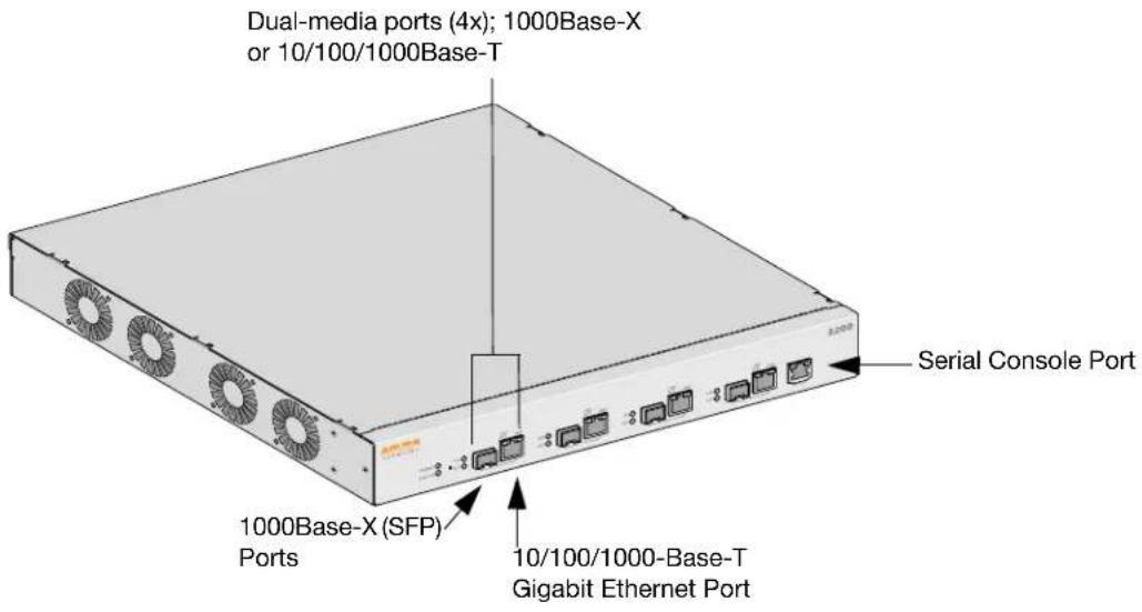
Figure 1 Aruba 3000 Series Front View
text_image
Dual-media ports (4x); 1000Base-X or 10/100/1000Base-T Serial Console Port 1000Base-X (SFP) Ports 10/100/1000-Base-T Gigabit Ethernet Port
Ports zero through three are dual-media ports and can utilize either the 1000Base-X or 10/100/1000Base-T connections provided. However, the 1000Base-X fiber connection has priority over the 10/100/1000Base-T copper connection. If a link is detected for the 1000Base-X interface, the 10/100/1000Base-T connection will be disabled.
1000Base-X (SFP) Ports
There are four 1000Base-X combination ports for fiber connectivity only and are intended for use with Aruba SFPs (mini-GBICs).
To purchase compatible SFP modules, contact your Aruba sales representative for details and assistance.

Aruba tests and supports Aruba optics within their controller systems. Third party optics are not tested or supported; therefore, Aruba does not guarantee proper functionality of third party optics when used in an Aruba system.
10/100/1000Base-T Gigabit Ethernet Ports
There are four 10/100/1000Base-T Gigabit Ethernet (RJ-45) ports. Gigabit Ethernet uses all eight wires and each pair is used in a bi-directional fashion, meaning the same pairs are used for both data transmission and reception. Figure 2 illustrates the CAT-5 pin-out found on an RJ-45 connector. The CAT-5 pin-out pairs the following pins on a 10/100/1000Base-T Gigabit Ethernet port: 1/2, 3/6, 4/5, and 7/8.
Figure 2 Gigabit Ethernet Port Pin-Out
1000Base-T Gigabit Ethernet Port
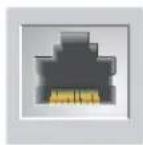
RJ-45 Female Pin-Out
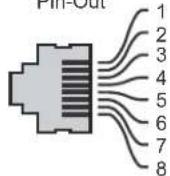
Signal Name
BI DA+ Bi-directional pair +A
BI-DA-Bi-directional pair-A
BI_DB+ Bi-directional pair +B
BI_DC+ Bi-directional pair +C
BI_DC- Bi-directional pair -C
BI_DB- Bi-directional pair -B
BI_DD+ Bi-directional pair +D
BI_DD- Bi-directional pair -D
Serial Console Port
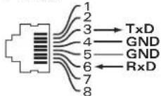
A serial console port is provided for connection to a terminal, allowing for direct local management. The port's RJ-45 female connector accepts an RS-232 serial cable with a male connector.
Figure 3 Serial Console Port Pin-Out
Serial Console Port
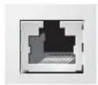
RJ-45 Female Pin-Out
Communication settings for the serial console port are indicated in Table 1.
Table 1 Console Terminal Settings
| Baud Rate | Data Bits | Parity | Stop Bits | Flow Control |
| 9600 8 None 1 None |

Do not connect an Access Point (AP) to the serial console port. The serial console port is compatible with only RS-232 devices. Non-RS-232 devices, such as APs, are not supported.
Serial Console Port Adaptor
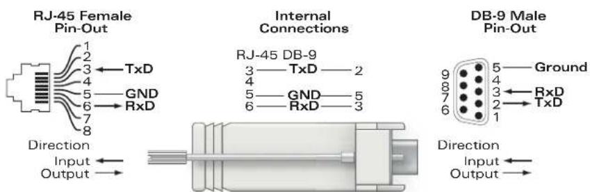
A modular adaptor can be used to convert the RJ-45 (female) connector to a DB9 (male) connector. Refer to Figure 4 for complete details.
Figure 4 RJ-45 (female) to DB9 (male) Modular Adaptor Conversion
text_image
RJ-45 Female Pin-Out 1 2 3 ← TxD 4 5 — GND 6 → RxD 7 8 Direction Input ← Output → Internal Connections RJ-45 DB-9 3 — TxD — 2 4 5 — GND — 5 6 — RxD — 3 DB-9 Male Pin-Out 9 — Ground 8 — RxD 7 — TxD 6 — 1 Direction Input ← Output →Rear View
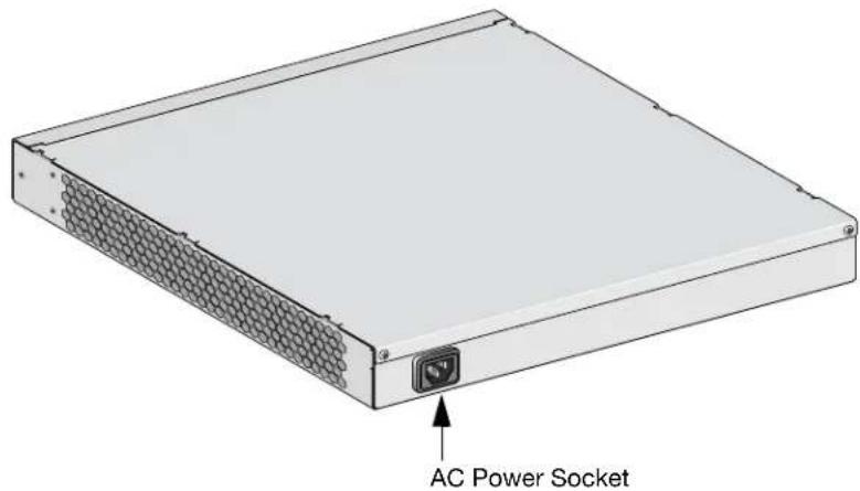
Figure 5 Aruba 3000 Series Rear View
text_image
AC Power SocketAC Power Socket
The Aruba 3000 Series supports integrated AC powering and the AC power socket on the rear of the unit is for use with an AC power cord (country-specific). Refer to Power Management Specifications on page 4 for power specification details.
LED Status Indicators
Table 2 Aruba 3000 Series LED Status Indicators
| LED Function Indicator Status | |||
| POWER Input Power Status | Indicator | On (Solid Green) Power on | |
| Off No power | |||
| STATUS Module Status Indicator On (Solid Green) Device is operational | |||
| On (Solid Red) Device failed | |||
| On (Solid Amber) Device is loading software | |||
| Off No power | |||
| LNK1000Base-X Ports | Link Status Indicator On (Solid Green) Link has been established | ||
| Off No link on port | |||
| ACT1000Base-X ports | Activity Status Indicator On (Blinking Green) Port is transmitting or receiving data | ||
| Off No activity | |||
| LNK/ACT10/100/1000Base-T Ports | Link/Activity Status Indicator | On (Solid Green) Link has been established | |
| On (Blinking Green) | Port is transmitting or receiving data | ||
Table 2 Aruba 3000 Series LED Status Indicators
| LED Function Indicator Status | |||
| Off No link on port | |||
| 100010/100/1000Base-T Ports | Interface SpeedIndicator | On (Solid Green) 1000 | Mbps interfacespeed in use |
| Off 10/100 Mbps | interface speed in use | ||
Installation
Pre-Installation Requirements
The following tools and equipment are required for installation of an Aruba 3000 Series controller:
- Rack Mount Bracket (2x)
- 6-32 x 1/4" Phillips Flat Head Screws (6x, included with rack mount brackets)
- 12-24 x 5/8" Phillips Flat Head Screws (4x, 19-inch (48.26 cm) rack system mount screws)
- Suitable Screwdrivers for both screw types
• AC power cord (country-specific)
Please only use included or Aruba specified cables, power cords, AC power supplies and batteries. The power cord should not be used with other electric equipment than what is specified by Aruba.

Physical Installation
Rack Mounting
To install an Aruba 3000 Series controller into a 19-inch (48.26 cm) rack system:
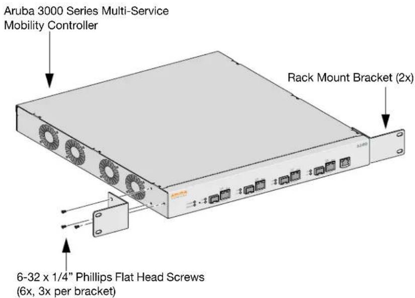
- Place a rack mount bracket over the mounting holes on one side of the controller (see Figure 1).
- Secure the bracket to the controller using three 6-32 x 1/4" phillips flat head screws and a suitable screwdriver (see Figure 1).
- Repeat these steps on the opposite side of the controller.
Figure 1 Rack Mount Brackets
text_image
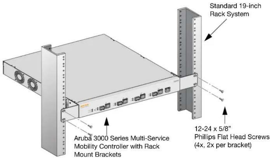
Aruba 3000 Series Multi-Service Mobility Controller Rack Mount Bracket (2x) 6-32 x 1/4" Phillips Flat Head Screws (6x, 3x per bracket)- Mount the controller within your organization's rack system using four 12-24 x 5/8" phillips flat head screws and a suitable screwdriver (see Figure 2).
Figure 2 Rack Mount Installation
text_image
Standard 19-inch Rack System Aruba 3000 Series Multi-Service Mobility Controller with Rack Mount Brackets 12-24 x 5/8" Phillips Flat Head Screws (4x, 2x per bracket)-
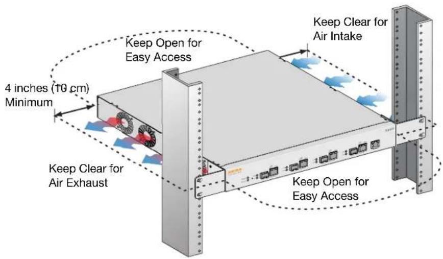
Leave a minimum of four inches (10 cm) of space on the left and right side of the unit for proper air flow and ventilation (see Figure 3).
-
Leave additional space in the front and back of the unit to access power cords, network cables, and LED status indicators (see Figure 3).
Figure 3 Air Flow Requirements
text_image
4 inches (10 cm) Minimum Keep Open for Easy Access Keep Clear for Air Exhaust Keep Clear for Air Intake Keep Open for Easy Access-
Connect the AC power cord (country-specific) to the rear of the unit.
-
Plug the opposite end of the power cord into an electrical outlet to power on the controller.

Aruba 3000 Series controllers do not have a switch for turning power to the unit on or off. Power to the unit is controlled by connecting or disconnecting the plug on the power cord to or from an electrical outlet.
Tabletop Deployment
To deploy an Aruba 3000 Series controller on a flat surface, such as a tabletop:
- Insert the four, rubber mounting feet into the bottom of the unit and place the unit on a flat, hard surface.
Initial Setup and Network Connectivity
Once the physical installation is complete, run the initial setup on the controller to configure the IP address and other basic system information. For complete details and instructions, refer to the ArubaOS Quick Start Guide for the software version installed on your controller.
Removal
To remove an Aruba 3000 Series controller from a 19-inch (48.26 cm) rack system:
- Disconnect power to the controller by unplugging the power cord from the electrical outlet.
- Loosen and remove the four rack system mount screws securing the controller to your organization's rack system.
- Remove the controller from the rack system.
Specifications
Physical Specifications
• Device Dimensions (without rack mount brackets) (HxWxD):
■ All Models: 1.75" x 13.8" x 11.7"
■ All Models: 44 mm x 351 mm x 297 mm
Device Weight (with rack mount brackets):
• Aruba 3200: 7.1 lbs/3.2 kgs
• Aruba 3400/Aruba 3600: 7.4 lbs/3.4 kgs
• Shipping Dimensions (HxWxD):
■ All Models: 6.5" x 18.2" x 16.5"
■ All Models: 165 mm x 462 mm x 419 mm
- Shipping Weight:
■ Aruba 3200: 9.4 lbs/4.3 kgs
■ Aruba 3400/Aruba 3600: 9.7 lbs/4.4 kgs
Power Management Specifications
Power Consumption
• Aruba 3200: 35 W maximum
• Aruba 3400: 45 W maximum
• Aruba 3600: 60 W maximum
Power Specifications (AC Input Requirements)
- Aruba 3200:
■ AC Input Voltage: 90-264 V\~, Universal Input
■ AC Input Current: 1.5 A
■ AC Input Frequency: 47-63 Hz
• Aruba 3400/Aruba 3600:
■ AC Input Voltage: 90-264 V\~, Universal Input
■ AC Input Current: 2.2 A
■ AC Input Frequency: 47-63 Hz
Operating Specifications
- Operating Temperature Range: 0°C to 40°C (32°F to 104°F)
- Operating Humidity Range: 5% to 95% (RH), non-condensing
Storage Specifications
• Storage Temperature Range: 0°C to 50°C (32°F to 122°F)
• Storage Humidity Range: 5% - 95% (RH), non-condensing
Safety and Regulatory Compliance
Aruba provides a multi-language document containing country specific restrictions and additional safety and regulatory information for all Aruba hardware products. The Aruba Safety and Regulatory Addendum can be viewed or downloaded from the following location: www.arubanetworks.com/pdf/0510272-01.pdf.

text_image
CLASS 1 LASER PRODUCT
Use of controls or adjustments of performance or procedures other than those specified in this manual may result in hazardous radiation exposure.
This product complies with 21 CFR Chapter 1, Subchapter J, Part 1040.10, and IEC 60825-1: 1993, A1: 1997, A2: 2001, IEC 60825-2: 2000.
For continued compliance with the above laser safety standards, only approved Class 1 modules from our approved vendors should be installed in Aruba products.
FCC Class A Device
This equipment has been tested and found to comply with the limits for a Class A digital device, pursuant to Part 15 of the FCC Rules. These limits are designed to provide reasonable protection against harmful interference when the equipment is operated in a commercial environment. This equipment generates, uses, and can radiate radio frequency energy and, if not installed and used in accordance with the instruction manual, may cause harmful interference to radio communications. Operation of this equipment in a residential area is likely to cause harmful interference in which case the user will be required to correct the interference at his own expense.
Indonesia Compliance
28975/SDPPI/2013 1912
28970/SDPPI/2013 1912
28974/SDPPI/2013 1912
Proper Disposal of Aruba Equipment
For the most current information on Global Environmental Compliance and Aruba products please see our website at www.arubanetworks.com.
Waste of Electrical and Electronic Equipment
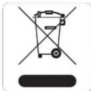
Aruba products at end of life are subject to separate collection and treatment in the EU Member States, Norway, and Switzerland and therefore are marked with the symbol shown at the left (crossed-out wheelie bin). The treatment applied at end of life of these products in these countries shall comply with the applicable national laws of countries implementing Directive 2002/96EC on Waste of Electrical and Electronic Equipment (WEEE).
European Union RoHS
RoHS
Aruba products also comply with the EU Restriction of Hazardous Substances Directive 2002/95/EC (RoHS). EU RoHS restricts the use of specific hazardous materials in the manufacture of electrical and electronic equipment. Specifically, restricted materials under the RoHS Directive are Lead (including Solder used in printed circuit assemblies), Cadmium, Mercury, Hexavalent Chromium, and Bromine. Some Aruba products are subject to the exemptions listed in RoHS Directive Annex 7 (Lead in solder used in printed circuit assemblies). Products and packaging will be marked with the “RoHS” label shown at the left indicating conformance to this Directive.
India RoHS
This product complies with RoHS requirements as prescribed by E-Waste (Management & Handling) Rules, governed by the Ministry of Environment & Forests, Government of India.
China RoHS

Aruba products also comply with China environmental declaration requirements and are labeled with the "EFUP e" label shown at the left.