
XPC XG41 - Compact computer Shuttle - Free user manual and instructions
Find the device manual for free XPC XG41 Shuttle in PDF.


User questions about XPC XG41 Shuttle
0 question about this device. Answer the ones you know or ask your own.
Ask a new question about this device
Download the instructions for your Compact computer in PDF format for free! Find your manual XPC XG41 - Shuttle and take your electronic device back in hand. On this page are published all the documents necessary for the use of your device. XPC XG41 by Shuttle.
USER MANUAL XPC XG41 Shuttle
©2011 by Shuttle® Inc. All Rights Reserved.
No part of this publication may be reproduced, transcribed, stored in a retrieval system, translated into any language, or transmitted in any form or by any means such as electronic, mechanical, magnetic, optical, chemical, photocopy, manual, or otherwise, without prior written permission from Shuttle® Inc.
Other brands and product names used herein are for identification purposes only and may be trademarks of their respective owners.
Disclaimer
Shuttle ^® Inc. shall not be liable for any incidental or consequential damages resulting from the performance or use of this product.
Shuttle ^® Inc. makes no representation or warranty regarding the contents of this manual. Information in this manual had been carefully checked for accuracy; however, no guarantee is given as to the correctness of the contents. For continuing product improvement, Shuttle ^® Inc. reserves the right to revise the manual or make changes to the specifications of this product at any time without notice and obligation to any person or entity regarding such change. The information contained in this manual is provided for general use by customers.
This device complies to Part 15 of the FCC Rules. Operation is subject to the following two conditions:
- This device may not cause harmful interference.
- This device must withstand any background interference including those that may cause undesired operation.
Trademarks
Shuttle is a registered trademark of Shuttle Inc.
Intel and Pentium are registered trademarks of Intel Corporation.
PS/2 is a registered trademark of IBM Corporation.
AWARD is a registered trademark of Award Software Inc.
Microsoft and Windows are registered trademarks of Microsoft Corporation.
General Notice
Other brand and product names used herein are for identification purposes only and may be trademarks of their respective owners.
Safety Information
Read the following precautions before setting up a Shuttle XPC.
CAUTION
Incorrectly replacing the battery may damage this computer. Replace only with the same or equivalent as recommended by Shuttle. Dispose of used batteries according to the manufacturer's instructions.
Laser compliance statement
The optical disc drive in this server is a laser product. The drive's classification label is lacated on the drive.
CLASS 1 LASER PRODUCT
CAUTION : INVISIBLE LASER RADIATION WHEN OPEN. AVOID EXPOSURE TO BEAM.
Installation Notices
Do not place this device underneath heavy loads or in an unstable position.

text_image
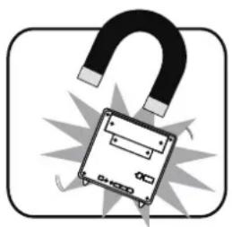
SHOOODo not use or expose this device around magnetic fields as magnetic interference may affect the performance of the device.
Do not expose this device to high levels of direct sunlight, high-humidity or wet conditions.

natural_image
Simple line drawing of a sun shining over a container with a handle, no text or symbols present.Do not block the air vents to this device or impede the airflow in any way.
natural_image
Illustration of a computer monitor with a U-shaped magnet above it, symbolizing data or control (no text or symbols present)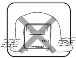
natural_image
Simple line drawing of a device with cross marks and wavy lines, no text or symbols presentTABLE OF CONTENTS
Driver and Software Installation....1
Mainboard Driver CD ....1
User Manuals 2
Appendix....3
Starting BIOS 3
Enter the BIOS ....3
Main Setup 5
Advanced 6
CPU Configuration 7
IDE Configuration....10
USB Configuration ....13
Onboard Device Configuration....15
Power Management Configuration....17
Hardware Health Configuration....19
Frequency Voltage Configuration 20
Boot 23
Boot Settings Configuration ......23
Boot Device Priority....25
Hard Disk Drives 26
Security 27
Exit 29
■ Motherboard Driver CD

The CD contents attached in XG41 Series motherboard are subject to change without notice.
The Motherboard Driver CD contains all the motherboard drivers necessary to optimize the performance of this Shuttle Xvision in a Windows® OS. Install these drivers after installing Microsoft® Windows®.
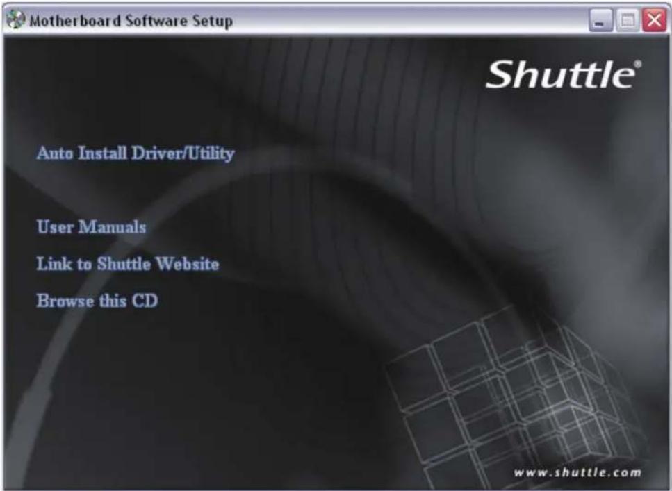
Insert the attached CD into your CD-ROM drive. The CD AutoRun screen should appear. If the AutoRun screen does not appear, double click on Autorun icon in My Computer to bring up Shuttle Mainboard Software Setup screen.
Navigation Bar Description :
Auto Install Driver/ Utility.
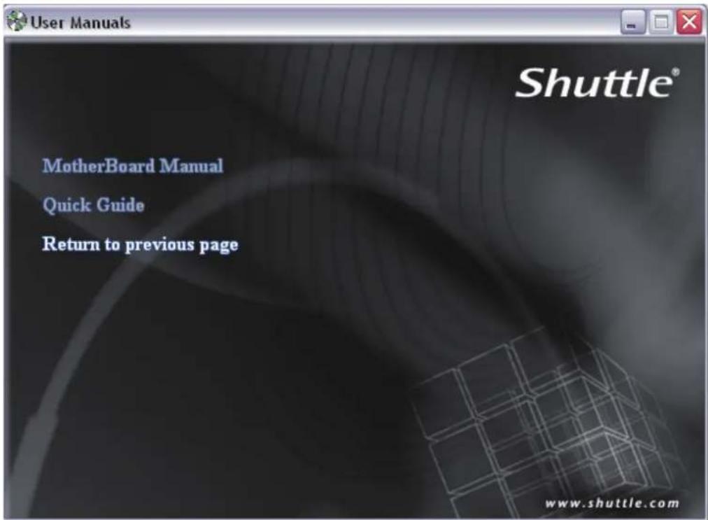
User Manuals - Motherboard Manual, Quick Guide.
Link to Shuttle Website - Link to shuttle website homepage.
Browse this CD - Allows you to see contents of this CD.
text_image
Motherboard Software Setup Shuttle® Auto Install Driver/Utility User Manuals Link to Shuttle Website Browse this CD www.shuttle.com■ User Manuals
Motherboard Manual
Quick Guide
text_image
User Manuals Shuttle® MotherBoard Manual Quick Guide Return to previous page www.shuttle.comStarting BIOS
AMIBIOS has been integrated into many motherboards for over a decade. In the past, people often referred to the AMIBIOS setup menu as BIOS, BIOS setup, or CMOS setup.
American Megatrends refers to this setup as BIOS. Specifically, it is the name of the AMIBIOS8 BIOS setup utility. This chapter describes the basic navigation of the BIOS setup screens.
Enter the BIOS
To enter the BIOS setup screens, follow the steps below:
Step1. Power on the motherboard.
Step2. Press the
Step3. After you press the

This manual describes the standard look of the BIOS setup screen. The motherboard manufacturer has the ability to change any and all of the settings described in this manual. This means that some of the options described in this manual do not exist in your motherboard's AMIBIOS.

In most cases, the
BIOS Setup Menu
The main BIOS setup menu is the first screen that you can navigate. Each main BIOS setup menu option is described in this user's guide.
The Main BIOS setup menu screen has two main frames. The left frame displays all the options that can be configured. "Grayed-out" options cannot be configured. Options is blue can be.
The right frame displays the key legend. Above the key legend is an area reserved for a text message. When an option is selected in the left frame, it is highlighted in white.
Often a text message will accompany it.

AMIBIOS8 has default text messages built into it. The motherboard manufacture retains the option to include, leave out, or change any of these text messages. They can also add their own text messages. Because of this, many screen shots in this manual are different from your BIOS setup screen.
The BIOS setup/utility uses a key-based navigation system called hot keys. Most of the BIOS setup utility hot keys can be used at any time during the setup navigation process. These keys include

There is a hot key legend located in the right frame on most BIOS setup screens.
| Hot Key Description | |
| → Left← Right | The Left and Rightkeys allow you to select a BIOS setup screen. For example: Main screen, Advanced screen, Chipset screen, and so on. |
| ↑ Up↓ Down | The Up and Downkeys allow you to select an BIOS setup item or sub-screen. |
| +- Plus/Minus | The Plus and Minuskeys allow you to change the field value of a particular setup item. For example: Date and Time. |
| Tab Thekey allows you to select BIOS setup fields. | |
| F1 | Thekey allows you to display the General Help screen. Press thekey to open the General Help screen. |
| F10 | Thekey allows you to save any changes you have made and exit BIOS Setup. Press thekey to save your changes. Press thekey to save the configuration and exit. You can also use thekey to select Cancel and then press thekey to abort this function and return to the previous screen. |
| ESC | Thekey allows you to discard any changes you have made and exit the BIOS Setup. Press thekey to exit the BIOS setup without saving your changes. Press thekey to discard changes and exit. You can also use thekey to select Cancel and then press thekey to abort this function and return to the previous screen. |
| Enter | Thekey allows you to display or change the setup option listed for a particular setup item. Thekey can also allow you to display the setup sub-screens. |

The

Main Setup
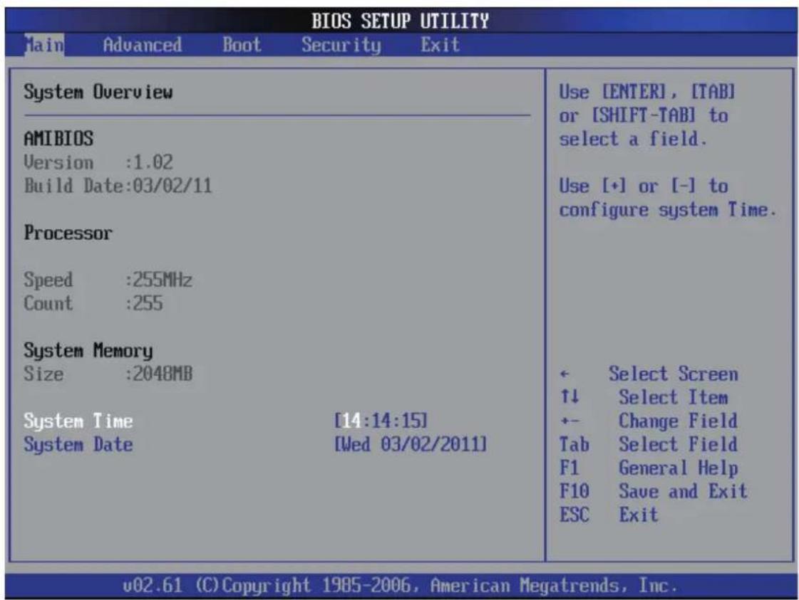
When you first enter the BIOS Setup Utility, you will enter the Main setup screen.
You can always return to the Main setup screen by selecting the Main tab. There are two Main Setup options. They are described in this section. The Main BIOS Setup screen is shown below.
text_image
BIOS SETUP UTILITY Main Advanced Boot Security Exit System Overview AMIBIOS Version :1.02 Build Date:03/02/11 Processor Speed :255MHz Count :255 System Memory Size :2048MB System Time [14:14:15] System Date [Wed 03/02/2011] Use [ENTER], [TAB] or [SHIFT-TAB] to select a field. Use [+] or [-] to configure system Time. ← Select Screen ↑↓ Select Item +- Change Field Tab Select Field F1 General Help F10 Save and Exit ESC Exit v02.61 (C) Copyright 1985-2006, American Megatrends, Inc.System Time/System Date
Use this option to change the system time and date. Highlight System Time or System Date using the

The time is in 24-hour format. For example, 5:30 A.M. appears as 05:30:00, and 5:30 P.M. as 17:30:00.

Advanced
Select the Advanced tab from the BIOS setup screen to enter the Advanced BIOS Setup screen. You can select any of the items in the left frame of the screen, such as CPU Configuration, to go to the sub menu for that item.
You can display an Advanced BIOS Setup option by highlighting it using the
The Advanced BIOS Setup screen is shown below. The sub menus are described on the following pages.
| BIOS SETUP UTILITY | |
| Main Advanced Boot Security Exit | |
| Advanced Settings WARNING: Setting wrong values in below sections may cause system to malfunction. ►CPU Configuration ►IDE Configuration ►USB Configuration ►OnBoard Device Configuration ►Power Management Configuration ►Hardware Health Configuration ►Frequency Voltage Configuration | Configure CPU. ← Select Screen ↑↓ Select Item Enter Go to Sub Screen F1 General Help F10 Save and Exit ESC Exit |
| v02.61 (C) Copyright 1985-2006, American Megatrends, Inc. | |
CPU Configuration
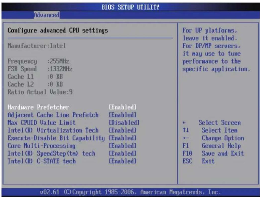
You can use this screen to select options for the CPU Configuration Settings. Use the up and down

The CPU Configuration setup screen varies depending on the installed processor.
text_image
BIOS SETUP UTILITY Advanced Configure advanced CPU settings Manufacturer:Intel Frequency :255MHz FSB Speed :1332MHz Cache L1 :0 KB Cache L2 :0 KB Ratio Actual Value:9 Hardware Prefetcher [Enabled] Adjacent Cache Line Prefetch [Enabled] Max CPUID Value Limit [Disabled] Intel(R) Virtualization Tech [Enabled] Execute-Disable Bit Capability [Enabled] Core Multi-Processing [Enabled] Intel(R) SpeedStep(tm) tech [Enabled] Intel(R) C-STATE tech [Enabled] For UP platforms, leave it enabled. For DP/MP servers, it may use to tune performance to the specific application. + Select Screen ↑↓ Select Item +- Change Option F1 General Help F10 Save and Exit ESC Exit v02.61 (C) Copyright 1985-2006, American Megatrends, Inc.Hardware Prefetcher
When enabled, the processor's hardware prefetcher will be enabled and allowed to automatically prefetch data and code for the processor. When disabled, the processor's hardware prefetcher will be disabled.
The choice: Enabled or Disabled.
Adjacent Cache Line Prefetch
When enabled, the processor will retrieve the currently requested cache line, as well as the subsequent cache line. When disabled, the processor will only retrieve the currently requested cache line.
The choice: Enabled or Disabled.
Max CPUID Value Limit
This item allows you to enable or disable the Max CPUID Value Limit. For Prescott CPU only, some OSes (ex. NT4.0) cannot handle the function with disable. This should be enabled in order to boot legacy OSes that cannot support CPUs with extended CPUID functions.
Set Limit CPUID MaxVal to 3, Should Be "Disabled" for WinXp.
The choice: Enabled or Disabled.

Some older O.S.'s (Win98, WinMe..) cannot handle a CPUID MaxVal greater than 3. Please choose "Enabled" if you use one of those O.S. If your O.S. is WinXP or Win2000, we suggest you "Disabled" the item.
Intel(R) Virtualization Tech
When enabled, a VMM can utilize the additional hardware capabilities provided by Vanderpool Technology.
The choice: Enabled or Disabled.

CPU support, item appear.
Execute-Disable Bit Capability
Execute Disable Bit functionality can help prevent certain classes of malicious buffer overflow attacks when combined with a supporting operating system. When disabled, forces the XD feature flag to always return 0.
The choice: Enabled or Disabled.

CPU support, item appear.
Core Multi-Processing
This item allows you to enable or disable the Core Multi-Processing. When disabled, it disables one execution core.
The choice: Enabled or Disabled.
Intel(R) SpeedStep(tm) tech
This item allows you to enable or disable the Intel(R) SpeedStep(tm) tech. Processor can switch between multiple frequency and voltage points to enable power savings.
The choice: Enabled or Disabled.
Intel (R) C-STATE tech
This item allows you to enable or disable the Intel( R) C-State tech. Processor can set to C2/C3/C4 when it is idle.
The choice: Enabled or Disabled.
IDE Configuration
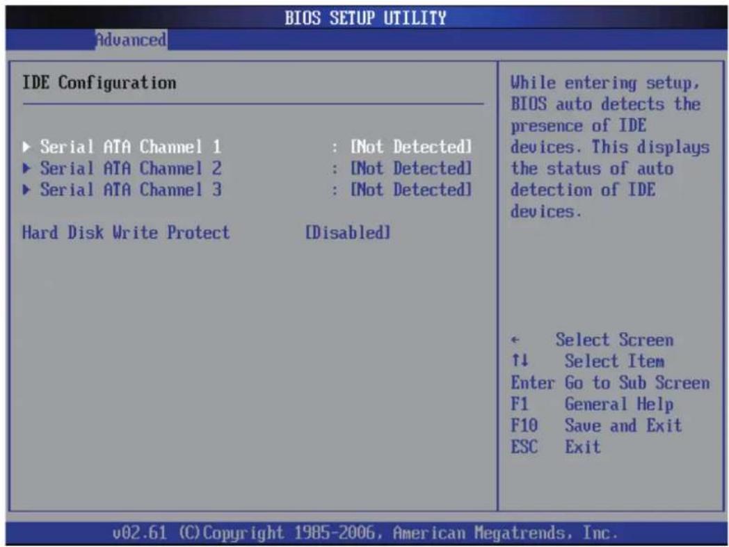
You can use this screen to select options for the IDE Configuration Settings. Use the up and down
text_image
BIOS SETUP UTILITY Advanced IDE Configuration ► Serial ATA Channel 1 : [Not Detected] ► Serial ATA Channel 2 : [Not Detected] ► Serial ATA Channel 3 : [Not Detected] Hard Disk Write Protect [Disabled] While entering setup, BIOS auto detects the presence of IDE devices. This displays the status of auto detection of IDE devices. ← Select Screen ↑↓ Select Item Enter Go to Sub Screen F1 General Help F10 Save and Exit ESC Exit v02.61 (C) Copyright 1985-2006, American Megatrends, Inc.Press
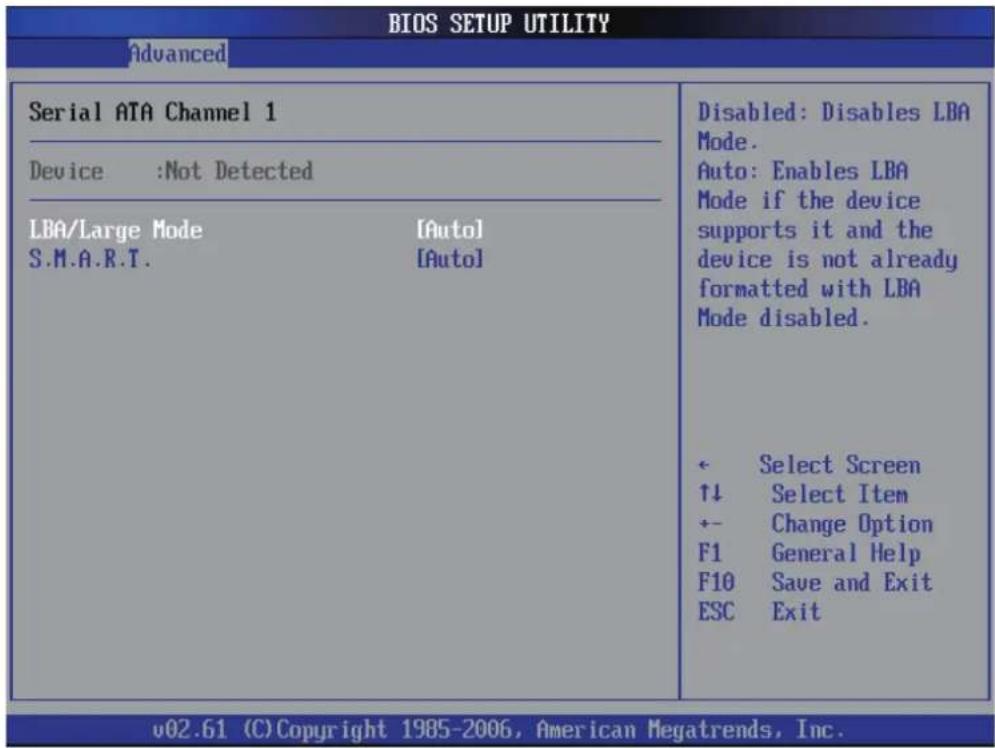
The screen is shown below.
text_image
BIOS SETUP UTILITY Advanced Serial ATA Channel 1 Device :Not Detected LBA/Large Mode [Auto] S.M.A.R.T. [Auto] Disabled: Disables LBA Mode. Auto: Enables LBA Mode if the device supports it and the device is not already formatted with LBA Mode disabled. ← Select Screen ↑↓ Select Item +- Change Option F1 General Help F10 Save and Exit ESC Exit v02.61 (C) Copyright 1985-2006, American Megatrends, Inc.Type
This option sets the type of device that the AMIBIOS attempts to boot from after the Power-On Self-Test (POST) has completed.
The choice: Not Installed, Auto, CD, ARMD.
LBA/Large Mode
LBA (Logical Block Addressing) is a method of addressing data on a disk drive. In LBA mode, the maximum drive capacity is 137 GB.
The choice: Disabled, Auto.

For drive capacities over 137 GB, your AMIBIOS must be equipped with 48-bit LBA mode addressing. If not, contact your motherboard manufacturer or install an ATA/133 IDE controller card that supports 48-bit LBA mode.
S.M.A.R.T.
Self-Monitoring Analysis and Reporting Technology (SMART) feature can help predict impending drive failures.
The choice: Auto, Enabled, Disabled.
Hard Disk Write Protect
Set this option to protect the hard disk drive from being overwritten. The Optimal and Fail-Safe default setting is Disabled.
Disabled:Set this value to allow the hard disk drive to be used normally. Read, write, and erase functions can be performed to the hard disk drive. This is the default setting.
Enabled:Set this value to prevent the hard disk drive from being erased.
The choice: Enabled, Disabled.
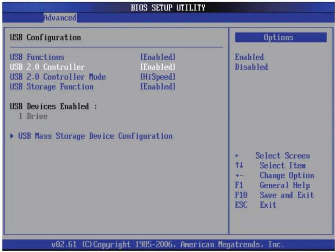
USB Configuration
You can use this screen to select options for the USB Configuration. Use the up and down
The screen is shown below.
text_image
BIOS SETUP UTILITY Advanced USB Configuration USB Functions [Enabled] USB 2.0 Controller [Enabled] USB 2.0 Controller Mode [HiSpeed] USB Storage Function [Enabled] USB Devices Enabled : 1 Drive ► USB Mass Storage Device Configuration Options Enabled Disabled ← Select Screen ↑↓ Select Item +- Change Option F1 General Help F10 Save and Exit ESC Exit v02.61 (C) Copyright 1985-2006, American Megatrends, Inc.USB Function
Set this value to allow the system to enable or disable the onboard USB ports. The Optimal and Fail-Safe default setting is Enabled.
Disabled: This setting makes the onboard USB ports unavailable.
Enabled: This setting allows the use of the USB ports. This is the default setting.
The choice: Enabled, Disabled.
USB 2.0 Controller
This item allows you to enable or disable the USB 2.0 Controller.
The choice: Enabled or Disabled.
USB 2.0 Controller Mode
Configures the USB 2.0 Controller in HiSpeed(480 Mbps) or FullSpeed(12Mbps).
The choice: HiSpeed or FullSpeed.
USB Storage Function
Enables support for legacy USB. AUTO option disables legacy support if no USB devices are connected.
The choice: Disabled, Enabled or Auto.
USB Mass Storage Device Configuration
Option are in its sub-menu.
Press
USB Mass Storage Reset Delay
It enables you to set the number of seconds the POST waits for the USB mass storage device after the start unit command is sent.
The choice: 10 Sec, 20 Sec, 30 Sec, 40 Sec.
Device #1
Read only.
Emulation Type
If Auto, USB devices less than 530 MB will be emulated as Floppy and remaining as hard drive. Forced FDD option can be used to force a HDD formatted drive to boot as FDD (Ex. ZIP drive)..
The choice: Auto, Floppy, Forced, FDD, Hard Disk, CDROM.
Onboard Device Configuration
You can use this screen to select options for the Onboard Device Configuration. Use the up and down
| BIOS SETUP UTILITY Advanced | |
| OnBoard Device Configuration | 0% = OFF, 100% = MAX |
| Panel LED Lightness Set [90%] | |
| Audio Controller [Enabled] | |
| Onboard Lan Device 1 [Enabled] | |
| Onboard Lan Device 2 [Enabled] | |
| LAN Remote Boot [Disabled] | |
| IGD Graphics Mode Select [32MB] | |
| DVMT Mode Select [DVMT Mode] | |
| DVMT/FIXED Memory [256MB] | |
| Serial Port1 IC [RS232] | ← Select Screen ↑↓ Select Item +- Change Option F1 General Help F10 Save and Exit ESC Exit |
| Serial Port1 Address [3F8/IRQ4] | |
| Serial Port2 Address [2F8/IRQ3] | |
| v02.61 (C)Copyright 1985-2006, American Megatrends, Inc. | |
Panel LED Lightness Set
This item allows you to control the brightness of Panel LED.
The choice: 0%, 10%, \~, 100%.
Audio Controller
This item allows you to enable or disable the Audio Controller.
The choice: Enabled, Disabled.
Onboard LAN Device 1
This item allows you to enable or disable the onboard LAN Device 1.
The choice: Enabled, Disabled.
Onboard LAN Device 2
This item allows you to enable or disable the onboard LAN Device 2.
The choice: Enabled, Disabled.
LAN Remote Boot
This item allows you to enable or disable the LAN Remote Boot.
The choice: Enabled, Disabled.
IGD Graphics Mode Select
This item allows you to set the IGD Graphics Mode Select.
The choice: 32MB, 64MB, 128MB.
DVMT Mode Select
This item allows you to set the DVMT Mode.
The choice: DVMT Mode, Fixed Mode.
DVMT/FIXED Memory
This item allows you to set the DVMT/FIXED Memory.
The choice:128MB, 256MB, Maximum DVMT.
Serial Port1 IC
This item allows you to change the mode of COM1.
The choice: RS232, RS422, RS485.
Serial Port1/Port2 Address
These options are used to assign the I/O address and interrupt request (IRQ) for the onboard serial port 1 and port 2.
The choice: Disabled, 3F8/IRQ4, 2F8/IRQ3, 3E8/IRQ4, and 2E8/IRQ3.
Power Management Configuration
You can use this screen to select options for the Power Management Configuration. Use the up and down
| BIOS SETUP UTILITY | |
| Advanced | |
| Power Management Configuration | Select the ACPI state used for System Suspend. |
| ACPI [Enabled] | |
| Suspend mode [S3 (STR)] | |
| Repost Video on S3 Resume [No] | |
| WatchDog Timer (s) [0] | |
| PowerOn Functions [Enabled] | |
| Resume On PCI/PCIEx LAN [Disabled] | |
| Resume On Ring [Disabled] | |
| Resume On RTC Alarm [Disabled] | |
| Restore on AC Power Loss [Power Off] | |
| ← Select Screen ↑↓ Select Item +- Change Option F1 General Help F10 Save and Exit ESC Exit | |
| v02.61 (C) Copyright 1985-2006, American Megatrends, Inc. | |
Suspend mode
Select the ACPI state used for System Suspend.
The choice: S1 (POS), S3 (STR).
Repost Video on S3 Resume
Determines whether to invoke VGA BIOS POST on S3/STR resume.
The choice: Yes, No.
WatchDog Timer (s)
This item allows you to set the time to reboot after POST.
The choice: 0\~255.
PowerOn Functions
This item allows you to enable/disable the PowerOn Functions.
The choice: Enabled, Disabled.
Resume On PCI/PCIEx LAN
This item allows you to enable/disable PCI/PCIEx LAN to generate.
The choice: Enabled, Disabled.
Resume On Ring
This item allows you to set Resume On Ring.
The choice: Enabled, Disabled.
Resume On RTC Alarm
This item allows you to set Resume On RTC Alarm.
The choice: Enabled, Disabled.
Restore on AC Power Loss
This item allows you to set Restore on AC Power Loss.
The choice: Power Off, Power On.
Hardware Health Configuration
You can use this screen to select options for the Hardware Health Configuration. Use the up and down
| Hardware Health Configuration | Fan configuration mode setting | |
| CPU FAN1 Speed Control | [ Smart Fan Model] | |
| System Temperature | :41°C/105°F | |
| CPU Temperature | :47°C/116°F | |
| CPU FAN1 Speed | :1250 RPM | |
| FAN1 Speed | :N/A | |
| +12.0U | :12.280 U | ← Select Screen↑↓ Select Item+- Change OptionF1 General HelpF10 Save and ExitESC Exit |
| +5.00U | :5.105 U | |
| +3.30U | :3.406 U | |
| CPU Core | :1.247 U | |
| UDIMM | :1.478 U | |
CPU Fan1 Speed Control
Here you can set the CPU Fan1 Speed.
The choice: Smart Fan Mode, Ultra-Low Speed, Low Speed, Mid Speed, or Full Speed.
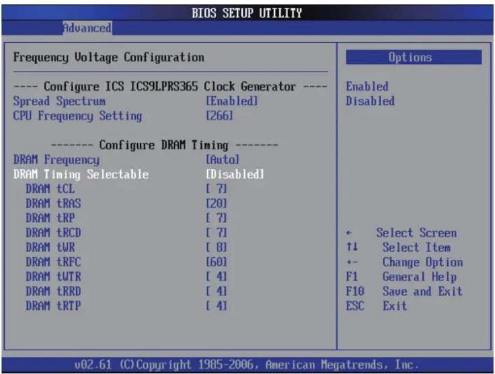
Frequency Voltage Configuration
You can use this screen to select options for the Frequency Voltage Configuration. Use the up and down
text_image
BIOS SETUP UTILITY Advanced Frequency Voltage Configuration ---- Configure ICS ICS9LPRS365 Clock Generator ---- Spread Spectrum [Enabled] CPU Frequency Setting [266] ---- Configure DRAM Timing ---- DRAM Frequency [Auto] DRAM Timing Selectable [Disabled] DRAM tCL [7] DRAM tRAS [20] DRAM tRP [7] DRAM tRCD [7] DRAM tWR [8] DRAM tRFC [60] DRAM tWTR [4] DRAM tRRD [4] DRAM tRTP [4] Options Enabled Disabled ← Select Screen ↑↓ Select Item +- Change Option F1 General Help F10 Save and Exit ESC Exit v02.61 (C) Copyright 1985-2006, American Megatrends, Inc.---- Configure ICS ICS9LPRS365 Clock Generator ----
Spread Spectrum
This item allows to set Clock Spread Spectrum for EMI Control.
The choice: Disabled or Enabled.
CPU Frequency Setting
This item allows to set CPU Host Frequency. BIOS auto detects the present CPU host frequency of this motherboard. The actual CPU host frequency will show in the following item.
Min: 133 Max: 400
➢ Key in a DEC number: (Between Min and Max.)
---- Configure DRAM Timing ----
DRAM Frequency
This item allows to set DRAM Frequency. If [Auto] is selected, the motherboard will detect the memory module(s) inserted and assigns appropriate frequency automatically.
The choice: Auto, 800MHz, 1066MHz.
DRAM Timing Selectable
Select [Enabled] will configure the following items by the contents in the SPD (Serial Presence Detect) device.
The choice: Disabled or Enabled.
DRAM tCL
When synchronous DRAM is installed, the number of clock cycles of CAS latency depends on the DRAM timing
The choice: 3 \~ 10.
DRAM tRAS
The precharge time is the number of cycles it takes for DRAM to accumulate its charge before refresh.
The choice: 9 \~ 24.
DRAM tRP
If an insufficient number of cycles is allowed for the RAS to accumulate its charge before DRAM refresh, the refresh may be-incompleted, and the DRAM may fail to retain data. Fast gives faster performance; and Slow gives more stable performance. This field is applied only when synchronous DRAM is installed in the system.
The choice: 3 \~ 10.
DRAM tRCD
This field lets you insert a timing delay between the CAS and RAS strobe signals, and you can use it when DRAM is written to, read from, or refreshed. Faster performance is gained in high speed, more stable performance, in low speed. This field is applied only when synchronous DRAM is installed in the system.
The choice: 3 \~ 10.
DRAM tWR
This item allows you to set Write Recovery Time.
The choice: 3 \~ 15
DRAM tRFC
This item allows you to set Write Recovery Time.
The choice: 3 \~ 15
DRAM tWTR
This item allows you to set Write to Read Delay.
The choice: 2 \~ 15.
DRAM tRRD
This item allows you to set Row Active Delay.
The choice: 2 \~ 15.
DRAM tRTP
This item allows you to set Read to Precharge Delay.
The choice: 2 \~ 15.

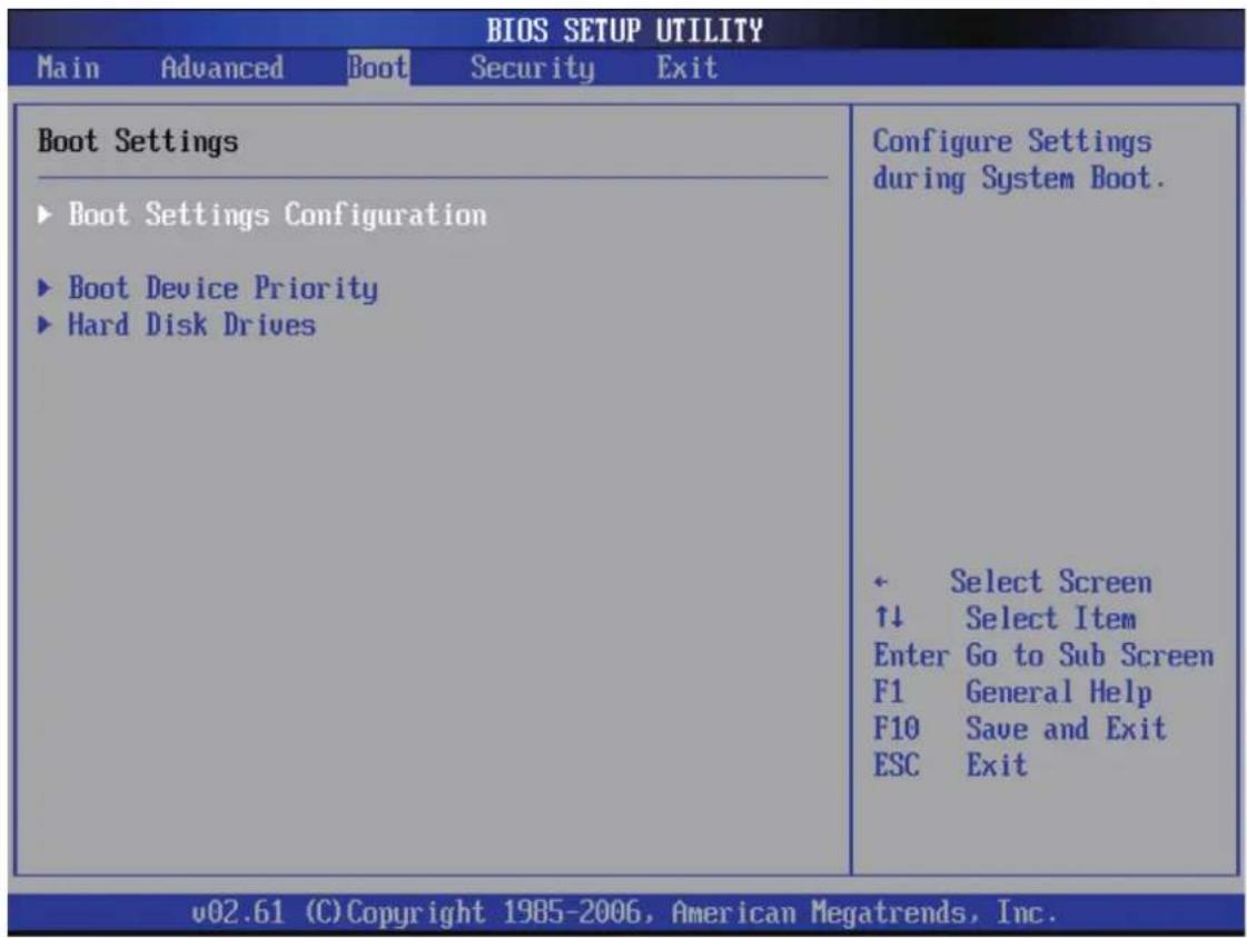
Boot
Select the Boot tab from the BIOS setup screen to enter the Boot BIOS Setup screen. You can select any of the items in the left frame of the screen, such as Boot Settings Configuration, to go to the sub menu for that item.
You can display an Boot BIOS Setup option by highlighting it using the
The Boot BIOS Setup screen is shown below. The sub menus are described on the following pages.
text_image
BIOS SETUP UTILITY Main Advanced Boot Security Exit Boot Settings ► Boot Settings Configuration ► Boot Device Priority ► Hard Disk Drives Configure Settings during System Boot. ← Select Screen ↑↓ Select Item Enter Go to Sub Screen F1 General Help F10 Save and Exit ESC Exit v02.61 (C)Copyright 1985-2006, American Megatrends, Inc.Boot Settings Configuration
You can use this screen to select options for the Boot Settings Configuration. Use the up and down
| BOOT | |
| Boot Settings ConfigurationFull Screen LOGO Show [Enabled]Bootup Num-Lock [Off] | Disabled: Displays normal POST messages. Enabled: Displays Logo instead of POST messages.< Select Screen↑↓ Select Item+- Change OptionF1 General HelpF10 Save and ExitESC Exit |
Full Screen LOGO Show
This item allows you to enable/disable the Full Screen LOGO Show.
Disabled: Displays normal POST messages.
Enabled: Displays Logo instead of POST messages.
The choice: Enabled, Disabled.
Boottup Nnum-Lock
Select Power-on state for Nnumlock.
The choice: On or Off.
Boot Device Priority
Use this screen to specify the order in which the system checks for the device to boot from. To access this screen, select Boot Device Priority on the Boot Setup screen and press

text_image
BIOS SETUP UTILITY Boot Boot Device Priority 1st Boot Device [CD/DVD: ] 2nd Boot Device [SATA: ] Specifies the boot sequence from the available devices. A device enclosed in parenthesis has been disabled in the corresponding type menu. ← Select Screen ↑↓ Select Item +- Change Option F1 General Help F10 Save and Exit ESC Exit v02.61 (C) Copyright 1985-2006, American Megatrends, Inc.To change the boot order, select a boot category type such as Hard disk drives, Removable Drives, or CD Drives from the boot menu.
For example, if the 1st boot device is set to Hard disk drives, then BIOS will try to boot to hard disk drives first.

When you select a boot category from the boot menu, a list of devices in that category appears. For example, if the system has three hard disk drives connected, then the list will show all three hard disk drives attached.
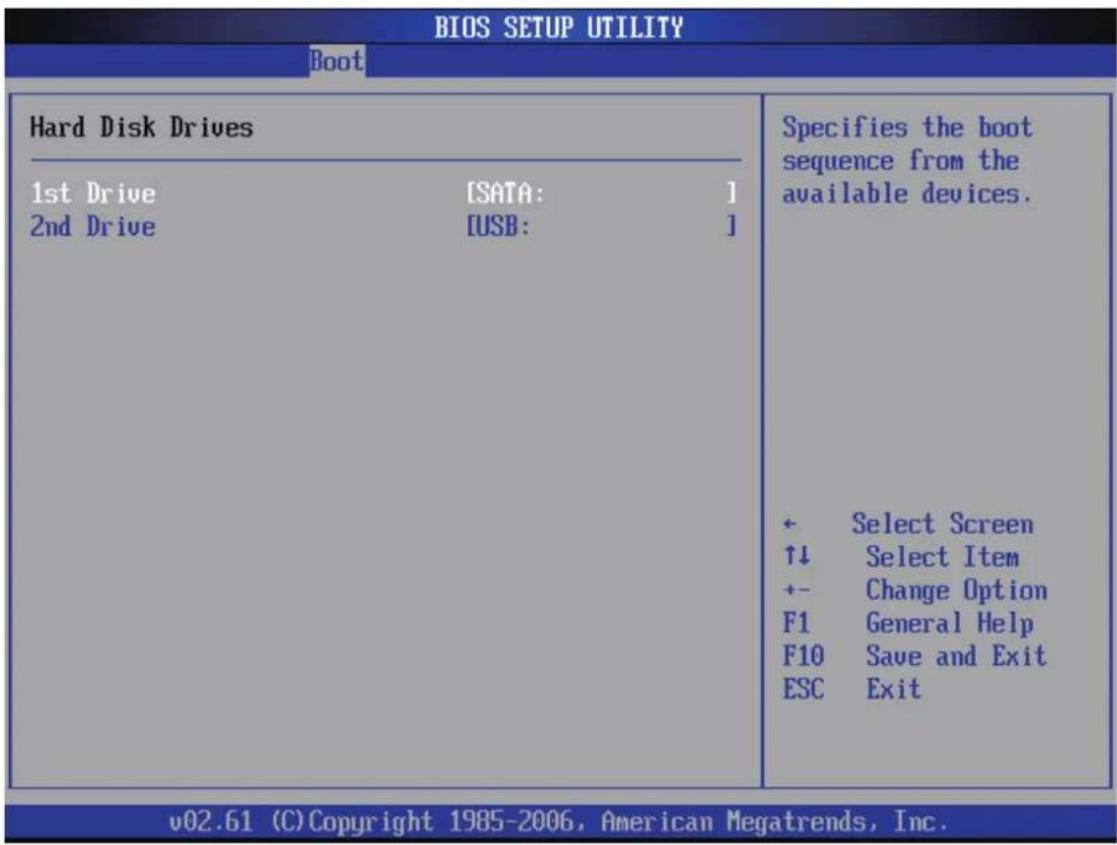
Hard Disk Drives /Removable Drives / CD Drives
Use this screen to view the Hard Disk Drives in the system. To access this screen, select Hard disk drives on the Boot Setup screen and press
text_image
BIOS SETUP UTILITY Boot Hard Disk Drives 1st Drive [SATA: ] 2nd Drive [USB: ] Specifies the boot sequence from the available devices. + Select Screen ↑↓ Select Item +- Change Option F1 General Help F10 Save and Exit ESC Exit v02.61 (C) Copyright 1985-2006, American Megatrends, Inc.Specifies the boot sequence from the available devices.

Security
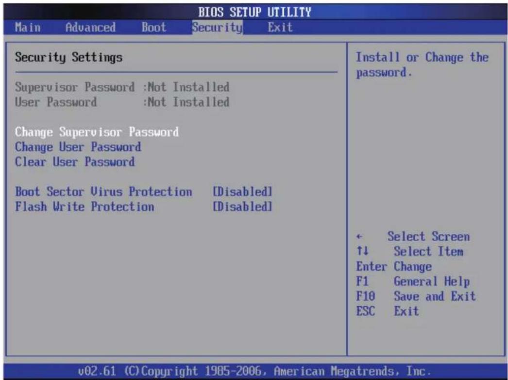
Select the Security tab from the BIOS setup screen to enter the Security BIOS Setup screen. You can display an Security BIOS Setup option by highlighting it using the
The Security Setup screen is shown below. The sub menus are documented on the following pages.
text_image
BIOS SETUP UTILITY Main Advanced Boot Security Exit Security Settings Supervisor Password :Not Installed User Password :Not Installed Change Supervisor Password Change User Password Clear User Password Boot Sector Virus Protection [Disabled] Flash Write Protection [Disabled] Install or Change the password. + Select Screen ↑↓ Select Item Enter Change F1 General Help F10 Save and Exit ESC Exit v02.61 (C) Copyright 1985-2006, American Megatrends, Inc.Supervisor Password
Indicates whether a supervisor password has been set. If the password has been installed, Installed displays. If not, Not Installed displays.
User Password
Indicates whether a user password has been set. If the password has been installed, Installed displays. If not, Not Installed displays.
Change Supervisor Password
Select Change Supervisor Password from the Security Setup menu and press
Enter New Password:
appears. Type the password and press
Change User Password
Select Change User Password from the Security Setup menu and press
Enter New Password:
appears. Type the password and press
Clear User Password
Select Clear User Password from the Security Setup menu and press
Clear New Password
[Ok] [Cancel]
appears. Type the password and press
Boot Sector Virus Protection
This option is near the bottom of the Security Setup screen. The Optimal and Fail-Safe default setting is Disabled.
[Disabled] Set this value to prevent the Boot Sector Virus Protection. This is the default setting.
[Enabled] Select Enabled to enable boot sector protection. Bios displays a warning when any program (or virus) issues a Disk Format command or attempts to write to the boot sector of the hard disk drive. If enabled, the following appears when a write is attempted to the boot sector. You may have to type N several times to prevent the boot sector write.
Boot Sector Write!
Possible VIRUS: Continue (Y/N)? _
The following appears after any attempt to format any cylinder, head, or sector of any hard disk drive via the BIOS INT 13 Hard disk drive Service:
Format!!!
Possible VIRUS: Continue (Y/N)? _
The choice: Enabled or Disabled.
Flash Write Protection
Choose [Enabled] to avoid virus destroy BIOS. If you want to flash BIOS, you must set it [Disabled].
The choice: Enabled or Disabled.
Exit
Select the Exit tab from the BIOS setup screen to enter the Exit BIOS Setup screen.
You can display an Exit BIOS Setup option by highlighting it using the
The Exit BIOS Setup screen is shown below.
| Main Advanced Boot Security Exit | |
| Exit Options Save Changes and Exit Exit Without Saving Changes Load Optimal Defaults | Exit system setup after saving the changes. F10 key can be used for this operation. ← Select Screen ↑↓ Select Item Enter Go to Sub Screen F1 General Help F10 Save and Exit ESC Exit |
| v02.61 (C) Copyright 1985-2006, American Megatrends, Inc. | |
Save Changes and Exit
When you have completed the system configuration changes, select this option to leave BIOS Setup and reboot the computer so the new system configuration parameters can take effect.
Select "Save Changes and Exit" from the Exit menu and press
Save Configuration Changes and Exit Now?
[Ok] [Cancel]
appears in the window. Select Ok to save changes and exit.
Exit without Saving Changes
Select "Exit without Saving Changes" from the Exit menu and press
Load Optimal Defaults
BIOS automatically sets all BIOS Setup options to a complete set of default settings when you Select this option. The Optimal settings are designed for maximum system performance, but may not work best for all computer applications. In particular, do not use the Optimal BIOS Setup options if your computer is experiencing system configuration problems.
Select Load Optimal Defaults from the Exit menu and press
Select Ok to load optimal defaults.