
Cius 7 - Graphic tablet CISCO - Free user manual and instructions
Find the device manual for free Cius 7 CISCO in PDF.


User questions about Cius 7 CISCO
0 question about this device. Answer the ones you know or ask your own.
Ask a new question about this device
Download the instructions for your Graphic tablet in PDF format for free! Find your manual Cius 7 - CISCO and take your electronic device back in hand. On this page are published all the documents necessary for the use of your device. Cius 7 by CISCO.
USER MANUAL Cius 7 CISCO
natural_image
Portrait of a man sitting on a sofa in an office setting (no visible text or symbols)Cisco Cius Administration Guide
Release 9.2(1)
Americas Headquarters
Cisco Systems, Inc.
170 West Tasman Drive
San Jose, CA 95134-1706
USA
http://www.cisco.com
Tel: 408 526-4000
800 553-NETS (6387)
Fax: 408 527-0883
THE SPECIFICATIONS AND INFORMATION REGARDING THE PRODUCTS IN THIS MANUAL ARE SUBJECT TO CHANGE WITHOUT NOTICE. ALL STATEMENTS, INFORMATION, AND RECOMMENDATIONS IN THIS MANUAL ARE BELIEVED TO BE ACCURATE BUT ARE PRESENTED WITHOUT WARRANTY OF ANY KIND, EXPRESS OR IMPLIED. USERS MUST TAKE FULL RESPONSIBILITY FOR THEIR APPLICATION OF ANY PRODUCTS.
THE SOFTWARE LICENSE AND LIMITED WARRANTY FOR THE ACCOMPANYING PRODUCT ARE SET FORTH IN THE INFORMATION PACKET THAT SHIPPED WITH THE PRODUCT AND ARE INCORPORATED HEREIN BY THIS REFERENCE. IF YOU ARE UNABLE TO LOCATE THE SOFTWARE LICENSE OR LIMITED WARRANTY, CONTACT YOUR CISCO REPRESENTATIVE FOR A COPY.
The following information is for FCC compliance of Class A devices: This equipment has been tested and found to comply with the limits for a Class A digital device, pursuant to part 15 of the FCC rules. These limits are designed to provide reasonable protection against harmful interference when the equipment is operated in a commercial environment. This equipment generates, uses, and can radiate radio-frequency energy and, if not installed and used in accordance with the instruction manual, may cause harmful interference to radio communications. Operation of this equipment in a residential area is likely to cause harmful interference, in which case users will be required to correct the interference at their own expense.
The following information is for FCC compliance of Class B devices: This equipment has been tested and found to comply with the limits for a Class B digital device, pursuant to part 15 of the FCC rules. These limits are designed to provide reasonable protection against harmful interference in a residential installation. This equipment generates, uses and can radiate radio frequency energy and, if not installed and used in accordance with the instructions, may cause harmful interference to radio communications. However, there is no guarantee that interference will not occur in a particular installation. If the equipment causes interference to radio or television reception, which can be determined by turning the equipment off and on, users are encouraged to try to correct the interference by using one or more of the following measures:
• Rcorient or relocate the receiving antenna.
- Increase the separation between the equipment and receiver.
- Connect the equipment into an outlet on a circuit different from that to which the receiver is connected.
- Consult the dealer or an experienced radio/TV technician for help.
Modifications to this product not authorized by Cisco could void the FCC approval and negate your authority to operate the product.
The Cisco implementation of TCP header compression is an adaptation of a program developed by the University of California, Berkeley (UCB) as part of UCB's public domain version of the UNIX operating system. All rights reserved. Copyright © 1981, Regents of the University of California.
NOTWITHSTANDING ANY OTHER WARRANTY HEREIN, ALL DOCUMENT FILES AND SOFTWARE OF THESE SUPPLIERS ARE PROVIDED "AS IS" WITH ALL FAULTS. CISCO AND THE ABOVE-NAMED SUPPLIERS DISCLAIM ALL WARRANTIES, EXPRESSED OR IMPLIED, INCLUDING, WITHOUT LIMITATION, THOSE OF MERCHANTABILITY, FITNESS FOR A PARTICULAR PURPOSE AND NONINFRINGEMENT OR ARISING FROM A COURSE OF DEALING, USAGE, OR TRADE PRACTICE.
IN NO EVENT SHALL CISCO OR ITS SUPPLIERS BE LIABLE FOR ANY INDIRECT, SPECIAL, CONSEQUENTIAL, OR INCIDENTAL DAMAGES, INCLUDING, WITHOUT LIMITATION, LOST PROFITS OR LOSS OR DAMAGE TO DATA ARISING OUT OF THE USE OR INABILITY TO USE THIS MANUAL, EVEN IF CISCO OR ITS SUPPLIERS HAVE BEEN ADVISED OF THE POSSIBILITY OF SUCH DAMAGES.
Cisco and the Cisco Logo are trademarks of Cisco Systems, Inc. and/or its affiliates in the U.S. and other countries. A listing of Cisco's trademarks can be found at www.cisco.com/go/trademarks. Third party trademarks mentioned are the property of their respective owners. The use of the word partner does not imply a partnership relationship between Cisco and any other company. (1005R)
Any Internet Protocol (IP) addresses and phone numbers used in this document are not intended to be actual addresses and phone numbers. Any examples, command display output, network topology diagrams, and other figures included in the document are shown for illustrative purposes only. Any use of actual IP addresses or phone numbers in illustrative content is unintentional and coincidental.
Cisco Cius Administration Guide
© 2011 Cisco Systems, Inc. All rights reserved.

natural_image
Portrait of a man sitting on a sofa in an office setting (no visible text or symbols)CONTENTS
Preface ix
Overview ix
Audience ix
Organization ix
Document Conventions x
Related Documentation xi
Obtaining Documentation, Support, and Security Guidelines xii
Cisco Product Security Overview xii
CHAPTER 1
Overview of Cisco Cius 1-1
Understanding Cisco Cius 1-2
Supported Networking Protocols 1-6
Supported Features on Cisco Cius 1-10
Feature Overview 1-10
Configuring Telephony Features 1-10
Configuring Network Parameters Using Cisco Cius 1-11
Providing Users with Feature Information 1-11
Understanding Security Features for Cisco Cius 1-11
Overview of Supported Security Features 1-13
Understanding Security Profiles 1-15
Identifying Secure (Encrypted) Phone Calls 1-16
Establishing and Identifying Secure Calls 1-16
Establishing and Identifying Secure Conference Calls 1-17
Call Security Interactions and Restrictions 1-17
Supporting 802.1X Authentication on Cisco Cius 1-18
Overview 1-18
Required Network Components 1-18
Requirements and Recommendations 1-18
Security Restrictions 1-19
Overview of Configuring and Installing Cisco Cius 1-19
Configuring Cisco Cius in Cisco Unified Communications Manager 1-20
Checklist for Configuring Cisco Cius in Cisco Unified Communications Manager 1-21
Installing Cisco Cius 1-24
Checklist for Installing Cisco Cius 1-24
Cisco Cius Administration Guide
CHAPTER 2
Preparing to Install Cisco Cius on Your Network 2-1
Understanding Interactions with Other Cisco Unified IP Telephony Products 2-1 Understanding How Cisco Cius Interacts with Cisco Unified Communications Manager 2-2 Understanding How Cisco Cius Interacts with the VLAN 2-2
Providing Power to Cisco Cius 2-3 Power Outage 2-3 Reducing Power Consumption on Cisco Cius 2-4 Power Negotiation over CDP or LLDP 2-4 Wi-Fi Power Management 2-4 Obtaining Additional Information About Power 2-4
Understanding the Cisco Cius Configuration Files 2-5 Understanding Cisco Cius Startup Process 2-6 Adding Cisco Cius Tablets to the Cisco Unified Communications Manager Database 2-8 Adding Cisco Cius Tablets with Auto-Registration 2-9 Adding Cisco Cius Tablets with Auto-Registration and TAPS 2-10 Adding Cisco Cius Tablets with Cisco Unified Communications Manager Administration 2-10 Adding Cisco Cius Tablets Using BAT Phone Template 2-11
Determining the MAC Address for Cisco Cius 2-12
CHAPTER 3
Setting Up Cisco Cius 3-1
Before You Begin 3-1 Network Requirements 3-1 Cisco Unified Communications Manager Configuration 3-2
Understanding Cisco Cius Components 3-2 Accessory Support on Cisco Cius 3-3 USB Port and USB Serial Console Data Information 3-3 Headsets 3-6
Audio Quality Subjective to the User 3-7 Wired Headsets 3-7 Bluetooth Wireless Headsets 3-7 Advanced Audio Distribution (A2DP) Profile 3-9 Hands-Free Profile 3-10 Important Note about Headset Types 3-10
Using External Devices 3-10 Video Displays 3-11
Installing Cisco Cius 3-11 Verifying Cisco Cius Startup Process 3-12
Configuring Startup Network Settings 3-12
Configuring Security on Cisco Cius 3-13
CHAPTER 4
Understanding the VoIP Wireless Network 4-1
Understanding the Wireless LAN 4-1
Understanding WLAN Standards and Technologies 4-2
802.11 Standards for WLAN Communications 4-3
World Mode (802.11.d) 4-4
Radio Frequency Ranges 4-5
802.11 Data Rates, Transmit Power, Ranges, and Decibel Tolerances 4-5
Wireless Modulation Technologies 4-5
AP, Channel, and Domain Relationships 4-6
WLANs and Roaming 4-6
Bluetooth Wireless Technology 4-7
Components of the VoIP Wireless Network 4-7
Interacting with Cisco Unified Wireless APs 4-7
Associating to APs 4-8
Voice QoS in a Wireless Network 4-8
Interacting with Cisco Unified Communications Manager 4-10
Security for Voice Communications in WLANs 4-10
Authentication Methods 4-11
Encryption Methods 4-11
Choosing AP Authentication and Encryption Methods 4-12
Configuring VoIP WLAN 4-12
Supported Access Points 4-12
Supported APs and Modes 4-12
Supported Antennas 4-13
Configuring Wireless LAN 4-13
CHAPTER 5
Configuring Features, Templates, Services, and Users 5-1
Telephony Features Available for Cisco Cius 5-2
Configuring Product-Specific Options 5-8
VPN Configuration from Cisco Unified Communications Operating System Administration
Guide 5-15
VPN Configuration Settings 5-16
VPN Authentication 5-16
AnyConnect VPN 5-17
Configuring Video Transmit Resolutions 5-17
Configuring Instant Messaging and Presence 5-18
Configuring Visual Voicemail 5-18
Configuring Web Proxy 5-20
Configuring Screen Lock and Display Idle Time Out 5-20
Configuring Screen Unlock/Password Reset 5-21
Virtual Desktop Infrastructure 5-22
Provisioning Applications 5-22
Modifying Phone Button Templates 5-23
Configuring Feature Control Policies 5-23
Configuring Reset Options/Load Upgrades 5-24
Adding Users to Cisco Unified Communications Manager 5-25
Managing the User Options Web Pages 5-25
Giving Users Access to the User Options Web Pages 5-26
CHAPTER 6
Configuring Settings on Cisco Cius 6-1
Setup Menus on Cisco Cius 6-1
Displaying a Setup Menu 6-2
Wireless & Network Settings Menu 6-2
TFTP Server Settings Menu 6-3
Wi-Fi Settings Menu 6-4
Ethernet Settings Menu 6-5
IP v4 Configuration Menu 6-7
Bluetooth Settings Menu Options 6-8
VPN Settings Menu Options 6-9
Location & Security Setup Menu 6-9
Enterprise Security Settings 6-9
Screen Lock/Unlock PIN/Password Reset 6-10
CHAPTER 7
Viewing Model Information, Status, and Statistics on Cisco Cius 7-1
Model Information 7-1
Status Menu 7-2
Status Messages Screen 7-3
Ethernet Statistics Screen 7-7
WLAN Statistics Screen 7-7
Call Statistics Screen (Audio) 7-8
Current Access Point Screen 7-9
CHAPTER 8
Monitoring Cisco Cius Remotely 8-1
Accessing the Web Page for Cisco Cius 8-2
Enabling and Disabling Web Page Access 8-3
Device Information 8-4
Network Setup 8-4
Network Statistics 8-8
Device Logs 8-11
Streaming Statistics 8-11
CHAPTER 9
Troubleshooting and Maintenance 9-1
General Troubleshooting 9-1
Resolving Startup Problems 9-4 Cisco Cius Does Not Register Properly 9-5
Cisco Cius Loses Connectivity with Cisco Unified Communications Manager 9-5
Verifying the Connection 9-5 Identifying Intermittent Network Outages 9-6
Verifying DHCP Settings 9-6 Checking Static IP Address Settings 9-6 Verifying the Voice VLAN Configuration 9-6 Verifying That Cisco Cius Has Not Been Intentionally Reset 9-6 Eliminating DNS or Other Connectivity Errors 9-7 Checking Power Connection 9-7
Troubleshooting Cisco Cius Security 9-7
Resetting Cisco Cius 9-8
Monitoring the Voice Quality of Calls 9-10 Troubleshooting Tips 9-10
Troubleshooting USB Console 9-11
Troubleshooting Configuration File Upgrades 9-11
Troubleshooting WLAN 9-11
Troubleshooting Instant Messaging and Presence 9-13
Troubleshooting User Experience Widgets 9-13
Where to Go for More Troubleshooting Information 9-13
APPENDIX A
Providing Information to Users Through a Website A-1
How Users Obtain Support for Cisco Cius A-1 Support for Cisco Cius A-1 Application Support A-2
Giving Users Access to the User Options Web Pages A-2
How Users Subscribe to Services and Configure Cisco Cius Features A-2
How Users Access a Voice Messaging System A-3
APPENDIX B
Supporting International Users B-1
Installing the Cisco Unified Communications Manager Locale Installer B-1
Support for International Call Logging B-1
APPENDIX C
Technical Specifications C-1
Physical and Operating Environment Specifications C-1
Cable Specifications C-2
Network and Computer Port Pinouts C-2
Network Port Connector Pinouts C-3
Computer Port Connector Pinouts C-3
Ports Used By Cisco Cius C-4
APPENDIX D
Basic Cisco Cius Administration Steps D-1
Example User Information for These Procedures D-1
Adding a User to Cisco Unified Communications Manager D-2
Adding a User From an External LDAP Directory D-2
Adding a User Directly to Cisco Unified Communications Manager D-2
Configuring Cisco Cius D-3
Performing Final End User Configuration Steps D-6
INDEX

natural_image
Portrait of a man sitting on a sofa in an office setting (no visible text or symbols)Preface
Overview
Cisco Cius Administration Guide provides the information to understand, install, configure, manage, and troubleshoot Cisco Cius on a VoIP network.
Because of the complexity of an IP telephony network, this guide does not provide complete and detailed information for procedures that you must perform in Cisco Unified Communications Manager or other network devices. See the “Related Documentation” section on page xi.
Audience
Network engineers, system administrators, or telecom engineers should review this guide to learn the steps required to properly set up Cisco Cius on the network.
The tasks described are administration-level tasks and are not intended for users of Cisco Cius tablets. Many of the tasks involve configuring network settings and affect the ability of Cisco Cius tablets to function in the network.
Because of the close interaction between Cisco Cius and Cisco Unified Communications Manager, many of the tasks in this manual require familiarity with Cisco Unified Communications Manager.
Organization
This guide comprises the following sections:
| Chapter Description | |
| Chapter 1, “Overview of Cisco Cius” | Provides a conceptual overview and description of Cisco Cius. |
| Chapter 2, “Preparing to Install Cisco Cius on Your Network” | Describes how Cisco Cius interacts with other key IP telephony components, and provides an overview of the tasks required prior to installation. |
| Chapter 3, “Setting Up Cisco Cius” | Describes how to properly and safely install Cisco Cius on your network. Also provides procedures on how to configure and add accessories, such as Bluetooth wireless headsets, to Cisco Cius. |
| Chapter 4, “Understanding the VoIP Wireless Network” | Provides an overview and describes the setup of the wireless local area network (WLAN) that Cisco Cius supports. |
| Chapter 5, “Configuring Features, Templates, Services, and Users” | Provides an overview of procedures for configuring features, setting up services, and adding users to Cisco Unified Communications Manager. |
| Chapter 6, “Configuring Settings on Cisco Cius” | Describes how to configure network settings, verify status, and make global changes to Cisco Cius. |
| Chapter 7, “Viewing Model Information, Status, and Statistics on Cisco Cius” | Explains how to view model information, status messages, network statistics, and firmware information from Cisco Cius. |
| Chapter 8, “Monitoring Cisco Cius Remotely” | Describes the information that you can obtain from the Cisco Cius web page to remotely monitor the operation of the tablet and to assist with troubleshooting. |
| Chapter 9, “Troubleshooting and Maintenance” | Provides tips for troubleshooting Cisco Cius. |
| Appendix A, “Providing Information to Users Through a Website” | Provides suggestions for setting up a website for providing users with important information about their Cisco Cius. |
| Appendix B, “Supporting International Users” | Provides information about setting up Cisco Cius in non-English environments. |
| Appendix C, “Technical Specifications” | Provides technical specifications of Cisco Cius. |
| Appendix D, “Basic Cisco Cius Administration Steps” | Provides procedures for basic administration tasks such as adding a user and Cisco Cius to Cisco Unified Communications Manager and then associating the user to Cisco Cius. |
Document Conventions
This document uses the following conventions:
| Convention Indication | |
| bold font | Commands and keywords and user-entered text appear in bold font. |
| italic font | Document titles, new or emphasized terms, and arguments for which you supply values are in italic font. |
| [ ] Elements in square brackets are optional. | |
| {x | y | z } | Required alternative keywords are grouped in braces and separated by vertical bars. |
| [x | y | z ] | Optional alternative keywords are grouped in brackets and separated by vertical bars. |
| string A nonquoted set of characters. Do not use quotation marks around the string or the string will include the quotation marks. | |
| courier font | Terminal sessions and information the system displays appear in courier font. |
| < > | Nonprinting characters such as passwords are in angle brackets. |
| [ ] | Default responses to system prompts are in square brackets. |
| !, # | An exclamation point (!) or a pound sign (#) at the beginning of a line of code indicates a comment line. |

Note Means reader take note.

Tip
Means the following information will help you solve a problem.

Caution
Means reader be careful. In this situation, you might perform an action that could result in equipment damage or loss of data.

Timesaver
Means the described action saves time. You can save time by performing the action described in the paragraph.

Warning
Means reader be warned. In this situation, you might perform an action that could result in bodily injury.
Related Documentation
For more information about Cisco Cius or Cisco Unified Communications Manager, see the following publications:
Cisco Cius
These publications are available at the following URL:
http://www.cisco.com/en/US/products/ps11156/tsd_products_support_series_home.html
• Cisco Cius Quick Start
• Cisco Cius User Guide
Other Cisco Cius documentation:
• Regulatory Compliance and Safety Information for Cisco Cius
• Cisco Cius Wireless LAN Deployment Guide
Cisco Unified Communications Manager Administration
Related publications are available at the following URL:
http://www.cisco.com/en/US/products/sw/voicesw/ps556/tsd_products_support_series_home.html
Cisco Unified Communications Manager Business Edition 5000
Related publications are available at the following URL:
http://www.cisco.com/en/US/products/ps7273/tsd_products_support_series_home.html
Cisco and the Environment
Related publications are available at the following URL:
http://www.cisco.com/go/ptrdocs
Obtaining Documentation, Support, and Security Guidelines
For obtaining documentation and support, providing documentation feedback, security guidelines, and also recommended aliases and general Cisco documents, see the monthly What's New in Cisco Product Documentation, which also lists all new and revised Cisco technical documentation, at:
http://www.cisco.com/en/US/docs/general/whatsnew/whatsnew.html
Subscribe to the What's New in Cisco Product Documentation as a Really Simple Syndication (RSS) feed and set content to be delivered directly to your desktop using a reader application. The RSS feeds are a free service and Cisco currently supports RSS Version 2.0.
Cisco Product Security Overview
This product contains cryptographic features and is subject to United States and local country laws governing import, export, transfer, and use. Delivery of Cisco cryptographic products does not imply third-party authority to import, export, distribute, or use encryption. Importers, exporters, distributors and users are responsible for compliance with U.S. and local country laws. By using this product you agree to comply with applicable laws and regulations. If you are unable to comply with U.S. and local laws, return this product immediately.
Further information regarding U.S. export regulations may be found at http://www.access.gpo.gov/bis/ear/ear_data.html.

natural_image
Portrait of a man sitting on a sofa in an office setting (no visible text or symbols)CHAPTER
Overview of Cisco Cius
Cisco Cius is a mobile collaboration tablet built for business. It is designed to help organizations capitalize on the value of mobility by enabling anywhere, anytime access to important business applications and features.
Cisco Cius includes the following features:
- Campus mobility with a choice of wired Gigabit Ethernet connectivity through handset media station or IEEE 802.11 a/b/g/n Wi-Fi connectivity
• An Intel Atom 1.6-GHz processor
• 1-GB RAM and 32-GB of eMMC flash memory - Native support for Bluetooth headsets
- Bluetooth profile support, including Hands-Free Profile and Advanced Audio Distribution (A2DP) Profile
• High-definition video through 7-inch (177.8 mm) high-resolution color screen.
• High-definition audio through integrated speakers - Microphone
- Front- and rear-facing cameras
- Detachable and serviceable 8-hour battery
Cisco Cius, like other network devices, must be configured and managed. Cisco Cius tablets encode G.711a-law, G.711 u-law, G.722, G.729a, G.729ab, and iLBC, and decode G.711a-law, G.711u-law, G.722, G.729, G.729a, G.729b, G.729ab, iSAC, iLBC, and H.264.
This chapter comprises the following topics:
• Understanding Cisco Cius, page 1-2
• Supported Networking Protocols, page 1-6
• Supported Features on Cisco Cius, page 1-10
• Understanding Security Features for Cisco Cius, page 1-11
• Overview of Configuring and Installing Cisco Cius, page 1-19

Using a mobile or GSM phone, or two-way radio in close proximity to Cisco Cius might cause interference. For more information, see the manufacturer documentation of the interfering device.
Understanding Cisco Cius
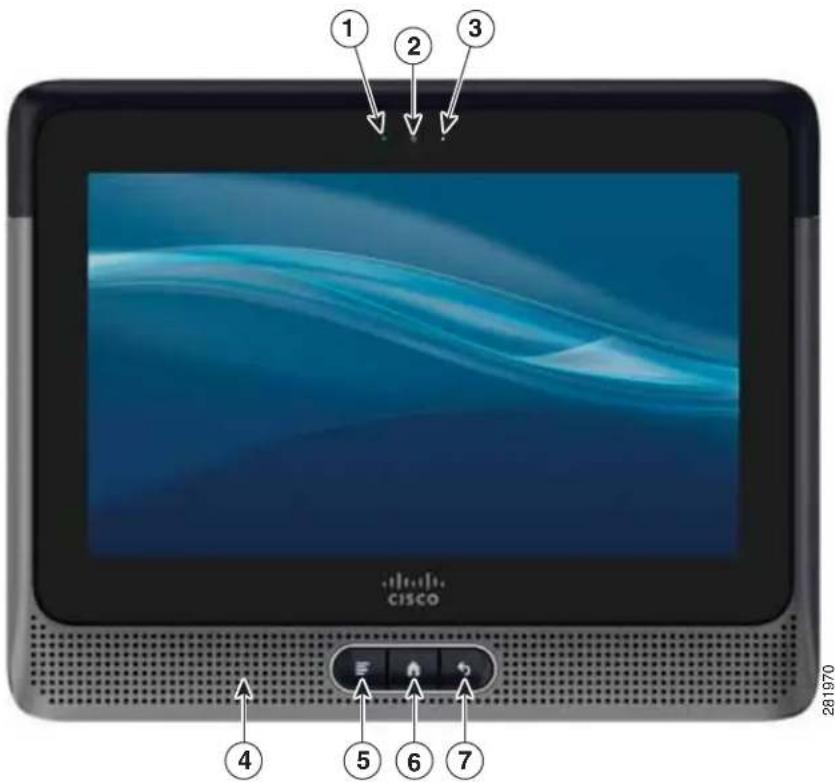
Figure 1-1 shows the front view of Cisco Cius.
Figure 1-1 Cisco Cius—Front View
text_image
1 2 3 CISCO 4 5 6 7 281970Table 1-1 describes the keys and components on the front of Cisco Cius.
Table 1-1 Cisco Cius Keys and Components—Front View
| No. Item | Description | |
| 1 Camera | LED Indicates video status | |
| 2 Front-facing camera | 1-megapixel camera | |
| 3 Light sensor | Ambient light sensor | |
| 4 | Speaker (one of two) | Two speakers (located on each side of keys) |
| 5 Menu key | Displays menu options | |
| 6 | Home key | Returns to the home screen |
| 7 | Back key | Returns to the previous screen |
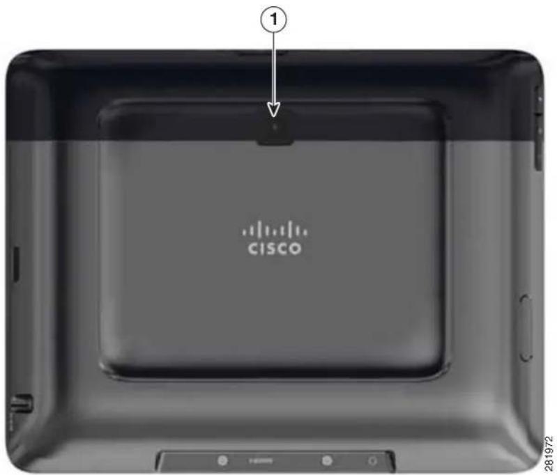
Figure 1-2 shows the back view of Cisco Cius.
Figure 1-2 Cisco Cius—Back View
text_image
CISCO 281972Table 1-2 describes the components on the back of Cisco Cius.
Table 1-2 Cisco Cius Components—Back View
| No. Item | Description | |
| 1 Rear-facing camera 5-megapixel camera | with 8X digital zoom | |
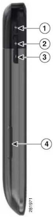
Figure 1-3 shows the left-side view of Cisco Cius.
Figure 1-3 Cisco Cius—Left Side
text_image
1 2 3 4 281971Table 1-3 describes the components on the left side of Cisco Cius.
Table 1-3 Cisco Cius Components—Left Side
| No. Item | Description | |
| 1 | Mute button Mutes speaker | |
| 2 | Volume Up button Turns speaker volume up | |
| 3 | Volume Down button Turns speaker volume down | |
| 4 | SIM slot Location for SIM card. (Future) |
Figure 1-4 shows the right-side view of Cisco Cius.
Figure 1-4 Cisco Cius—Right Side

text_image
① ② 281973Table 1-4 describes the components on the right side of Cisco Cius.
Table 1-4 Cisco Cius Features—Right Side
| No. Item | Description | |
| 1 Battery | release Provides means for removing battery | |
| 2 Power | port Connects to external power supply |
Figure 1-5 shows the top view of Cisco Cius.
Figure 1-5 Cisco Cius—Top View

text_image
1234 281974Table 1-5 describes the components on the top of Cisco Cius.
Table 1-5 Cisco Cius Features—Top View
| No. Item | Description | |
| 1 | Micro-USB port For Android Debug Bridge (ADB) access to get Cisco Cius debug data or to copy files to and from PC. Cannot attach mouse or other accessories | |
| 2 | MicroSD card slot | Location for MicroSD card |
| 3 Microphone — | ||
| 4 | Power button | Turns unit on and off. |
Figure 1-6 shows the bottom view of Cisco Cius.
Figure 1-6 Cisco Cius—Bottom View

text_image
281969 ① ② ③ ②Table 1-6 describes the components on the bottom of Cisco Cius.
Table 1-6 Cisco Cius Features—Bottom View
| No. Item | Description | |
| 1 | Headset port | 3.5 mm single-plug stereo headphone connection |
| 2 | Dock ports | Connects to Cisco Cius media station |
| 3 HDMI | port Type-D mini-HDMI | |
Supported Networking Protocols
Cisco Cius supports several industry-standard and Cisco networking protocols that are required for voice communication. Table 1-7 provides an overview of the networking protocols that Cisco Cius supports.
Table 1-7 Supported Networking Protocols on Cisco Cius
| Networking Protocol Purpose | Usage Notes | |
| Bluetooth Bluetooth is a wireless personal area network (WPAN) protocol that specifies how devices communicate over short distances. | Cisco Cius supports Bluetooth 2.1+EDR.Cisco Cius supports Hands-Free Profile (HFP) and Advanced Audio Distribution (A2DP) Profile. | |
| Bootstrap Protocol (BootP) BootP enables a network device, such as Cisco Cius, to discover certain startup information, such as its IP address. | — | |
| Cisco Discovery Protocol (CDP) | CDP is a device-discovery protocol that runs on all Cisco-manufactured equipment. Using CDP, a device can advertise its existence to other devices and receive information about other devices in the network. | Cisco Cius uses CDP to communicate information such as auxiliary VLAN ID, per port power-management details, and Quality of Service (QoS) configuration information with the Cisco Catalyst switch. |
| Cisco Peer-to-Peer Distribution Protocol (CPPDP) | CPPDP is a Cisco proprietary protocol that is used to form a peer-to-peer hierarchy of devices. This hierarchy distributes firmware files from peer devices to their neighboring devices. | The Peer Firmware Sharing feature uses CPPDP. |
| Dynamic Host Configuration Protocol (DHCP) | DHCP dynamically allocates and assigns an IP address to network devices.DHCP enables you to connect Cisco Cius into the network and have Cisco Cius become operational without your needing to manually assign an IP address or to configure additional network parameters. | DHCP is enabled by default. If DHCP is disabled, you must manually configure the IP address, gateway, netmask, and a TFTP server on Cisco Cius locally.Cisco recommends that you use DHCP custom option 150. With this method, you configure the TFTP server IP address as the option value. For additional supported DHCP configurations, see the following chapters in the Cisco Unified Communications Manager System Guide: · Dynamic Host Configuration Protocol · Cisco TFTPIf you cannot use option 150, try using DHCP option 66. |
| Hypertext Transfer Protocol (HTTP) | HTTP is the standard way of transferring information and moving documents across the Internet and the web. | Cisco Cius uses HTTP for XML services and for troubleshooting purposes. |
| Hypertext Transfer Protocol Secure (HTTPS) | HTTPS is a combination of the Hypertext Transfer Protocol with the SSL/TLS protocol to provide encryption and secure identification of servers and for transferring Cisco Cius firmware images. | Web applications with both HTTP and HTTPS support have two URLs configured. |
| IEEE 802.1X The IEEE 802.1 | X standard defines a client-server-based access control and authentication protocol that restricts unauthorized clients from connecting to a LAN through publicly accessible ports.Until the client is authenticated, 802.1X access control allows only Extensible Authentication Protocol over LAN (EAPOL) traffic through the port to which the client is connected. After authentication is successful, normal traffic can pass through the port. | Cisco Cius implements the IEEE 802.1X standard by providing support for the following authentication methods: EAP-FAST and EAP-TLS, PEAP, and CCKM.After 802.1X authentication is enabled on Cisco Cius, disable the PC port on the media station and voice VLAN. See the “Supporting 802.1X Authentication on Cisco Cius” section on page 1-18 for additional information. |
| IEEE 802.11a/b/g/n The IEEE | 802.11 standard specifies how devices communicate over a wireless local area network (WLAN).802.11a operates at the 5 GHz band and 802.11b and 802.11g operate at the 2.4 GHz band.802.11.n operates in either 2.4 GHz or 5Ghz band. | The 802.11 interface is a deployment option for cases when Ethernet cabling is unavailable or undesirable. |
| Internet Protocol (IP) IP is a messageing protocol that addresses and sends packets across the network. | To communicate using IP, network devices must have an assigned IP address, gateway, and netmask.IP address, gateway, and netmask identifications are automatically assigned if you are using Cisco Cius with DHCP. If you are not using DHCP, you must manually assign these properties to each Cisco Cius locally. | |
| Link Layer Discovery Protocol (LLDP) | LLDP is a standardized network discovery protocol (similar to CDP) that is supported on some Cisco and third-party devices. | — |
| Link Layer Discovery Protocol-Media Endpoint Devices (LLDP-MED) | LLDP-MED is an extension of the LLDP standard developed for voice products. | Cisco Cius supports LLDP-MED on the media station switch port to communicate information such as:Voice VLAN configurationDevice discoveryPower managementInventory managementFor more information about LLDP-MED support, see the LLDP-MED and Cisco Discovery Protocol white paper at this URL:http://www.cisco.com/en/US/technologies/tk652/tk701/technologies_white_paper0900aecd804cd46d.html |
| Real-Time Transport Protocol (RTP) | RTP is a standard protocol for transporting real-time data, such as interactive voice and video, over data networks. | Cisco Cius uses RTP to send and receive real-time voice and video traffic from other devices and gateways. |
| Real-Time Control Protocol (RTCP) | RTCP works in conjunction with RTP to provide QoS data (such as jitter, latency, and round-trip delay) on RTP streams. RTCP is also used to synchronize the audio and video stream in order to provide a better video experience. | RTCP is disabled by default, but you can use Cisco Unified Communications Manager to enable it on a per-tablet basis. |
| Session Description Protocol (SDP) | SDP is the portion of the SIP protocol that determines which parameters are available during a connection between two endpoints. Conferences are established by using only the SDP capabilities that are supported by all endpoints in the conference. | SDP capabilities, such as codec types, DTMF detection, and comfort noise, are normally configured on a global basis by Cisco Unified Communications Manager or Media Gateway in operation. Some SIP endpoints may allow these parameters to be configured on the endpoint itself. |
| Session Initiation Protocol (SIP) | SIP is the IETF standard for multimedia conferencing over IP. SIP is an ASCII-based application-layer control protocol (defined in RFC 3261) that can be used to establish, maintain, and terminate calls between two or more endpoints. | Like other VoIP protocols, SIP is designed to address the functions of signaling and session management within a packet telephony network. Signaling allows call information to be carried across network boundaries. Session management provides the ability to control the attributes of an end-to-end call. |
| Transmission Control Protocol (TCP) | TCP is a connection-oriented transport protocol. | Cisco Cius uses TCP to connect to Cisco Unified Communications Manager and to access XML services. |
| Transport Layer Security TLS | is a standard protocol for securing and authenticating communications. | Cisco Cius uses the TLS protocol after registering with Cisco Unified Communications Manager securely. |
| Trivial File Transfer Protocol (TFTP) | TFTP allows you to transfer files over the network.On Cisco Cius, TFTP enables you to obtain a configuration file specific to Cisco Cius. | TFTP requires a TFTP server in your network, that can be automatically identified from the DHCP server. If you want Cisco Cius to use a TFTP server other than the one specified by the DHCP server, you must use the Network Configuration menu on Cisco Cius to assign the IP address of the TFTP server manually.For more information, see the “Cisco TFTP” chapter in the Cisco Unified Communications Manager System Guide. |
| User Datagram Protocol (UDP) | UDP is a connectionless messaging protocol for delivery of data packets. | Cisco Cius transmits and receives RTP streams, which utilize UDP. |
Related Topics
• Understanding Interactions with Other Cisco Unified IP Telephony Products, page 2-1
• Understanding Cisco Cius Startup Process, page 2-6
• Ethernet Settings Menu, page 6-5
Supported Features on Cisco Cius
Cisco Cius is a business tablet that delivers anytime, anywhere access to Cisco Collaboration applications, including Unified Communications features. Cisco Cius also provides access to other business and Android applications.
This section comprises the following topics:
• Feature Overview, page 1-10
- Configuring Telephony Features, page 1-10
- Configuring Network Parameters Using Cisco Cius, page 1-11
• Providing Users with Feature Information, page 1-11
Feature Overview
Cisco Cius is a mobile collaboration tablet for business. Cisco Cius provides an integrated suite of collaborative applications, including Cisco Quad, Cisco WebEx, Cisco Unified Presence, instant messaging, email, visual voice mail, and Cisco Unified Communications Manager voice and video telephony features. Cisco Cius also provides Virtual Desktop Infrastructure (VDI) and cloud computing and support for a wide range of applications through Cisco AppHQ Developer Network Marketplace. Cisco Cius also supports applications from the Google Android Marketplace. For an overview of the features that Cisco Cius supports and for tips on configuring them, see Chapter 5, “Configuring Features, Templates, Services, and Users.”
As with other network devices, you must configure Cisco Cius to prepare to access Cisco Unified Communications Manager and the rest of the IP network. By using DHCP, you have fewer settings to configure on Cisco Cius, but if your network requires it, you can manually configure an IP address, TFTP server, netmask information, and so on. For instructions on configuring the network settings on Cisco Cius, see the “Setup Menus on Cisco Cius” section on page 6-1.
Finally, because Cisco Cius is a network device, you can obtain detailed status information from it directly. This information can assist you with troubleshooting problems that users might encounter when using their Cisco Cius tablets. See Chapter 7, “Viewing Model Information, Status, and Statistics on Cisco Cius” for more information.
Related Topics
- Configuring Settings on Cisco Cius, page 6-1
- Configuring Features, Templates, Services, and Users, page 5-1
• Troubleshooting and Maintenance, page 9-1
Configuring Telephony Features
You can modify settings for Cisco Cius from Cisco Unified Communications Manager Administration. Use this web-based application to set up Cisco Cius registration criteria and calling search spaces, to configure corporate directories and services, and to modify phone button templates, among other tasks.
For more information, see the “Telephony Features Available for Cisco Cius” section on page 5-2 and the Cisco Unified Communications Manager Administration Guide. You can also use the context-sensitive help available within the application for guidance.
You can access Cisco Unified Communications Manager documentation at this location:
http://www.cisco.com/en/US/products/sw/voicesw/ps556/tsd_products_support_series_home.html
You can access Cisco Unified Communications Manager Business Edition 5000 documentation at this location:
http://www.cisco.com/en/US/products/ps7273/tsd_products_support_series_home.html
Configuring Network Parameters Using Cisco Cius
You can configure parameters, such as DHCP, TFTP, and IP settings, on the Cisco Cius tablet. You can also obtain statistics about a current call or firmware versions on Cisco Cius.
For more information about configuring features and viewing statistics from Cisco Cius, see Chapter 6, "Configuring Settings on Cisco Cius" and Chapter 7, "Viewing Model Information, Status, and Statistics on Cisco Cius."
Providing Users with Feature Information
You are likely the primary source of information for Cisco Cius users in your network or company. To ensure that you distribute the most current feature and procedural information, familiarize yourself with Cisco Cius documentation. Make sure to visit the Cisco Cius website:
http://www.cisco.com/en/US/products/ps11156/tsd_products_support_series_home.html
From this site, you can view the user guide and quick start documentation.

Note
The Cisco Cius User Guide is also available directly through a link on the tablet. Choose Settings > About Cius > Cisco Cius User Guide.
In addition to providing documentation, it is important to inform users about available Cisco Cius features, including those specific to your company or network, and about how to access and customize those features, if appropriate.
For a summary of some of the key information that Cisco Cius users may need, see Appendix A, "Providing Information to Users Through a Website."
Understanding Security Features for Cisco Cius
Implementing security in the Cisco Unified Communications Manager system prevents data tampering, and prevents call-signaling and media-stream tampering of the Cisco Cius and the Cisco Unified Communications Manager server.
To alleviate these threats, the Cisco IP telephony network establishes and maintains secure (encrypted) communication streams between Cisco Cius and the server, digitally signs files before they are transferred to Cisco Cius, and encrypts media streams and call signaling between Cisco Cius tablets.
Cisco Cius uses a security profile that defines whether the device is nonsecure or secure. For information about applying the security profile to the device, see the Cisco Unified Communications Manager Security Guide.
If you configure security-related settings in Cisco Unified Communications Manager Administration, the phone configuration file contains sensitive information. To ensure the privacy of a configuration file, you must configure the file for encryption. For detailed information, see the "Configuring Encrypted Phone Configuration Files" chapter in Cisco Unified Communications Manager Security Guide.
Table 1-8 shows where you can find information about security in this and other documents.
Table 1-8 Cisco Cius and Cisco Unified Communications Manager Security Topics
| Topic Reference | |
| Detailed explanation of security, including setup, configuration, and troubleshooting information for Cisco Unified Communications Manager and Cisco Cius | See the Cisco Unified Communications Manager Security Guide. |
| Security features supported on Cisco Cius | See the “Overview of Supported Security Features” section on page 1-13.See the Cisco Cius Wireless LAN Deployment Guide. |
| Restrictions regarding security features | See the “Security Restrictions” section on page 1-19. |
| Viewing a security profile name | Table 1-9 provides an overview of the security features that Cisco Cius supports. For more information about these features and about Cisco Unified Communications Manager and Cisco Unified IP Phone security, see the Cisco Unified Communications Manager Security Guide. |
| Identifying phone calls for which security is implemented | See the “Identifying Secure (Encrypted) Phone Calls” section on page 1-16. |
| TLS connection | See the “Supported Networking Protocols” section on page 1-6.See the “Adding Cisco Cius Tablets with Cisco Unified Communications Manager Administration” section on page 2-10. |
| Security and Cisco Cius startup process | See the “Understanding Cisco Cius Startup Process” section on page 2-6. |
| Security and Cisco Cius configuration files | See the “Adding Cisco Cius Tablets with Cisco Unified Communications Manager Administration” section on page 2-10. |
| Changing the TFTP Server 1 or TFTP Server 2 option on Cisco Cius after security is implemented | See the “TFTP Server Settings Menu” section on page 6-3. |
| Items on the Security Setup menu that you access from Cisco Cius | See the “Location & Security Setup Menu” section on page 6-9. |
| Disabling access to a tablet web page | See the “Enabling and Disabling Web Page Access” section on page 8-3. |
| Troubleshooting | See the “Troubleshooting Cisco Cius Security” section on page 9-7.See the Cisco Unified Communications Manager Security Guide. |
| Deleting the CTL/ITL file from Cisco Cius | See the“Resetting Cisco Cius” section on page 9-8. |
| Resetting or restoring Cisco Cius | See the “Resetting Cisco Cius” section on page 9-8. |
| 802.1X Authentication for Cisco Cius See these sections:Supporting 802.1X Authentication on Cisco Cius, page 1-18.Enterprise Security Settings, page 6-9.Troubleshooting Cisco Cius Security, page 9-7 | |
Overview of Supported Security Features
Table 1-9 provides an overview of the security features that Cisco Cius supports. For more information about these features and about Cisco Unified Communications Manager and Cisco Cius security, see the Cisco Unified Communications Manager Security Guide and the “Wireless Security” chapter of the Cisco Cius Wireless LAN Deployment Guide.
For information about current security settings on Cisco Cius, press the Menu key and choose Settings > Location and security. For more information, see the “Location & Security Setup Menu” section on page 6-9.
Table 1-9 Overview of Security Features
| Feature Description | |
| Image authentication | Signed binary files (with the extension .sbn) prevent tampering with the firmware image before it is loaded on a Cisco Cius tablet. Tampering with the image causes Cisco Cius to fail the authentication process and reject the new image. |
| Customer-site certificate installation | Each Cisco Cius requires a unique certificate for device authentication. Cisco Cius tablets include a manufacturing installed certificate (MIC), but for additional security, you can specify in Cisco Unified Communications Manager Administration that a certificate be installed by using the Certificate Authority Proxy Function (CAPF). Alternatively, you can install a Locally Significant Certificate (LSC) from the Enterprise security menu on the tablet. See the “Configuring Security on Cisco Cius” section on page 3-13 for more information. |
| Device authentication | Occurs between the Cisco Unified Communications Manager server and Cisco Cius when each entity accepts the certificate of the other entity. Determines whether a secure connection between Cisco Cius and Cisco Unified Communications Manager occurs and, if necessary, creates a secure signaling path between the entities by using TLS protocol. Cisco Unified Communications Manager will not register Cisco Cius tablets unless Cisco Unified Communications Manager can authenticate them. |
| File authentication | Validates digitally signed files that Cisco Cius downloads. Cisco Cius validates the signature to make sure that file tampering did not occur after file creation. Files that fail authentication are not written to Flash memory on Cisco Cius. Cisco Cius rejects such files without further processing. |
| File encryption Encryption prevents sensitive information from being revealed while the file is in transit to Cisco Cius. In addition, Cisco Cius validates the signature to make sure that file tampering did not occur after file creation. Files that fail authentication are not written to Flash memory on the Cius. Cisco Cius rejects such files without further processing. | |
| Signaling Authentication | Uses the TLS protocol to validate that no tampering has occurred to signaling packets during transmission. |
| Manufacturing installed certificate | Each Cisco Cius contains a unique manufacturing-installed certificate (MIC), which is used for device authentication. The MIC provides permanent unique proof of identity for the tablet and allows Cisco Unified Communications Manager to authenticate Cisco Cius. |
| Media encryption | Uses SRTP to ensure that the media streams between supported devices are secure and that only the intended device receives and reads the data. Includes creating a media master key pair for the devices, delivering the keys to the devices, and securing the delivery of the keys. |
| CAPF (Certificate Authority Proxy Function) | Implements parts of the certificate generation procedure that are too processing-intensive for Cisco Cius, and interacts with Cisco Cius for key generation and certificate installation. The CAPF can be configured to request certificates from customer-specified certificate authorities on behalf of Cisco Cius, or it can be configured to generate certificates locally. |
| Security profiles | Defines whether Cisco Cius is nonsecure, authenticated, encrypted, or protected. For more information about these features and about Cisco Unified Communications Manager and Cisco Cius security, see the Cisco Unified Communications Manager Security Guide. |
| Encrypted configuration files | Lets you ensure the privacy of Cisco Cius configuration files. |
| Optional disabling of the web server functionality for Cisco Cius | For security purposes, you can prevent access to a Cisco Cius web page (which indicates a variety of operational statistics for the tablet) and user options pages. For more information, see the “Enabling and Disabling Web Page Access” section on page 8-3. |
| Phone hardening Additional security options, which you control from Cisco Unified Communications Manager Administration:Disabling PC port on the media stationDisabling Gratuitous ARP (GARP)Disabling PC Voice VLAN accessProviding restricted access to the web applicationsDisabling Bluetooth Accessory PortDisabling access to web pagesRequiring a screen lockControlling access to Google Android market.Controlling access to installation of applications from unknown sources | |
| 802.1X Authentication | Cisco Cius can use 802.1X authentication to request and gain access to the network. See the “Supporting 802.1X Authentication on Cisco Cius” section on page 1-18 for more information. |
| Secure SIP Failover for SRST | After you configure an SRST reference for security and then reset the dependent devices in Cisco Unified Communications Manager Administration, the TFTP server adds the SRST certificate to the Cisco Cius cnf.xml file and sends the file to the tablet. A secure tablet then uses a TLS connection to interact with the SRST-enabled router. |
| Signaling encryption | Ensures that all SIP signaling messages that are sent between the device and the Cisco Unified CM server are encrypted. |
Related Topics
• Identifying Secure (Encrypted) Phone Calls, page 1-16
• Security Restrictions, page 1-19
Understanding Security Profiles
All Cisco Cius tablets that support Cisco Unified Communications Manager use a security profile, which defines whether the tablet is nonsecure, authenticated, or encrypted. For information about configuring the security profile and applying the profile to the tablet, see the Cisco Unified Communications Manager Security Guide.
To view the security mode that is set for Cisco Cius, view the Signaling security mode setting in the Enterprise security settings menu.
Related Topics
• Identifying Secure (Encrypted) Phone Calls, page 1-16
• Security Restrictions, page 1-19
Identifying Secure (Encrypted) Phone Calls
Security is implemented for Cisco Cius by enabling the “Protected Device” parameter from the Cisco Unified Communications Manager Administration Phone window. When security is implemented, you can identify secure phone calls by the Secure Call icon on the Cisco Cius screen. In a secure call, all call signaling and media streams are encrypted. A secure call offers a high level of security, providing integrity and privacy to the call. When a call in progress is being encrypted, the Security Mode status on Cisco Cius Enterprise security settings menu indicates “Encrypted.”

Note
If the call is routed through non-IP call legs (for example, PSTN), the call may be nonsecure even though it is encrypted within the IP network and has a lock icon associated with it.
In a secure call, a 2-second tone plays to notify the users when a call is encrypted and both devices are configured as protected devices, and if secure tone features are enabled on Cisco Unified Communications Manager. The tone plays for both parties when the call is answered. The tone does not play unless both devices are protected and the call occurs over encrypted media. If the system determines that the call is not encrypted, Cisco Cius plays a nonsecure indication tone (6 beeps) to alert the user that the call is not protected. For a detailed description of the secure indication tone feature and the configuration requirements, see the Cisco Unified Communications Manager Security Guide.

Note
Video is transmitted as nonsecure. So, even if both Cisco Cius tablets are secure, the “Encrypted” lock icon will not be displayed for video calls.
Related Topics
• Understanding Security Features for Cisco Cius, page 1-11
• Security Restrictions, page 1-19
Establishing and Identifying Secure Calls
A secure call is established when your Cisco Cius and a phone on the other end are configured for secure calling. They can be in the same Cisco IP network, or on a network outside the IP network. A secure conference call is established by using this process:
- A user initiates the call from a secured Cisco Cius (Encrypted security mode).
- Cisco Cius indicates the "Encrypted" status on the Enterprise security menu. This status indicates that Cisco Cius is configured for secure calls, but does not mean that the other connected phone is also secured.
- A security tone plays if the call is connected to another secured device, indicating that both ends of the conversation are encrypted and secured. Otherwise, nonsecure tone will be played.

Note
Secure tone is played only when enabled on Cisco Unified Communications Manager. If disabled on Cisco Unified Communications Manager, no secure tone will be played even the call is secure. For more information, see the “Configuring Secure and Nonsecure Indication Tones” chapter of the Cisco Unified Communications Manager Security Guide.
Establishing and Identifying Secure Conference Calls
You can initiate a secure conference call and monitor the security level of participants. A secure conference call is established by using this process:
- A user initiates the conference from a secure Cisco Cius tablet.
- Cisco Unified Communications Manager assigns a secure conference bridge to the call.
- As participants are added, Cisco Unified Communications Manager verifies the security mode of each device and maintains the secure level for the conference.
- Cisco Cius indicates the security level of the conference call.

Various interactions, restrictions, and limitations affect the security level of the conference call, depending on the security mode of the participant devices and the availability of secure conference bridges. See Table 1-12 and Table 1-13 for information about these interactions. Cisco Cius supports secure audio conference calls only; video will not be secure.
Call Security Interactions and Restrictions
Cisco Unified Communications Manager checks the Cisco Cius security status when conferences are established and changes the security indication for the conference or blocks completion of the call to maintain integrity and also security in the system. Table 1-10 provides information about changes to call security levels when Barge is used.
Table 1-10 Call Security Interactions When Barge Is Used
| Initiator Device Security Level | Feature Used Call Security | Level Results of Action | |
| Nonsecure | Barge | Encrypted call | Call barged and identified as nonsecure call |
| Secure | Barge | Encrypted call | Call barged and identified as secure call |
Table 1-11 provides information about changes to conference security levels depending on the initiator device security level, the security levels of participants, and the availability of secure conference bridges.
Table 1-11 Security Restrictions with Conference Calls
| Initiator Device Security Level | Feature Used | Security Level of Participants | Results of Action |
| Nonsecure | Conference | Secure | Nonsecure conference bridgeNonsecure conference |
| Secure | Conference | At least one member is nonsecure | Secure conference bridgeNonsecure conference |
| Secure | Conference | Secure | Secure conference bridgeSecure encrypted level conference |
Supporting 802.1X Authentication on Cisco Cius
These sections provide information about 802.1X support on Cisco Cius:
• Overview, page 1-18
• Required Network Components, page 1-18
- Requirements and Recommendations, page 1-18
Overview
Cisco Cius and Cisco Catalyst switches traditionally use Cisco Discovery Protocol (CDP) to identify each other and determine parameters such as VLAN allocation and inline power requirements. Cisco Cius also uses CDP; however, CDP does not identify any locally attached PCs; therefore, an EAPOL pass-through mechanism is used, whereby a PC that is attached locally to Cisco Cius may pass EAPOL messages to the 802.1X authenticator in the LAN switch. This mechanism prevents Cisco Cius from having to act as the authenticator, yet allows the LAN switch to authenticate a data endpoint before accessing the network.
In conjunction with the EAPOL pass-through mechanism, Cisco Cius provides a proxy EAPOL-Logoff mechanism. If the locally attached PC disconnects from Cisco Cius, the LAN switch does not detect the physical link fail, because the link between the LAN switch and Cisco Cius is maintained. To avoid compromising network integrity, Cisco Cius sends an EAPOL-Logoff message to the switch on behalf of the downstream PC, and this action triggers the LAN switch to clear the authentication entry for the downstream PC.
Cisco Cius contains an 802.1X supplicant in addition to the EAPOL pass-through mechanism. This supplicant allows network administrators to control the connectivity of Cisco Cius to the LAN switch ports. The current release of the 802.1X supplicant uses the EAP-FAST and EAP-TLS options for network authentication.
Required Network Components
Support for 802.1X authentication on Cisco Cius requires several components, including the following:
- Cisco Cius—Cisco Cius acts as the 802.1X supplicant, which initiates the request to access the network.
- Cisco Catalyst Switch (or other third-party switch)—The switch must support 802.1X, so that it can act as the authenticator and pass the messages between Cisco Cius and the authentication server. When the exchange is completed, the switch grants or denies access to the network to the tablet.
Requirements and Recommendations
The requirements and recommendations for 802.1X authentication on Cisco Cius include the following:
- Enable 802.1X Authentication—If you want to use the 802.1X standard to authenticate Cisco Cius, be sure that you properly configure the other components before enabling 802.1X authentication on the tablet. See the “Enterprise Security Settings” section on page 6-9 for more information.
- Configure PC Port on Media Station—The 802.1X standard does not take into account the use of VLANs and thus recommends that only a single device be authenticated to a specific switch port. However, some switches (including Cisco Catalyst switches) support multidomain authentication. The switch configuration determines whether you can connect a PC to a Cisco Cius media station PC port.
- Enabled—If you are using a switch that supports multidomain authentication, you can enable the media station PC port and connect a PC to it. In this case, Cisco Cius supports proxy EAPOL-Logoff to monitor the authentication exchanges between the switch and the attached PC. For more information about IEEE 802.1X support on the Cisco Catalyst switches, see the Cisco Catalyst switch configuration guides at:
http://www.cisco.com/en/US/products/hw/switches/ps708/tsd_products_support_series_home.html
- Disabled—If the switch does not support multiple 802.1X-compliant devices on the same port, disable the media station PC Port when 802.1X authentication is enabled. See the “Ethernet Settings Menu” section on page 6-5 for more information. If you do not disable this port and subsequently attempt to attach a PC to it, the switch denies network access to both the tablet and the PC.
- Configure Voice VLAN—Because the 802.1X standard does not account for VLANs, configure this setting based on the switch support.
- Enabled—If you are using a switch that supports multidomain authentication, continue to use the voice VLAN.
- Disabled—If the switch does not support multidomain authentication, disable the Voice VLAN and consider assigning the port to the native VLAN. See the “Ethernet Settings Menu” section on page 6-5 for more information.
Security Restrictions
A user cannot barge in to an encrypted call if the Cisco Cius tablet that is used to barge is not configured for encryption. When barge fails in this case, a fast busy tone plays on the Cisco Cius on which the user initiated the barge.
If the initiator Cisco Cius tablet is configured for encryption, the barge initiator can barge in to a nonsecure call from the encrypted Cisco Cius tablet. After the barge occurs, Cisco Unified Communications Manager classifies the call as nonsecure.
If the initiating Cisco Cius is configured for encryption, the barge initiator can barge in to an encrypted call, and Cisco Cius indicates that the call is encrypted.
Overview of Configuring and Installing Cisco Cius
When deploying a new IP telephony system, system administrators and network administrators must complete several initial configuration tasks to prepare the network for IP telephony service. For information and a checklist for setting up and configuring a Cisco IP telephony network, see the “System Configuration Overview” chapter in the Cisco Unified Communications Manager System Guide.
After you set up the IP telephony system and configure system-wide features in Cisco Unified Communications Manager, you can add Cisco Cius to the system.
The following topics provide an overview of procedures for adding Cisco Cius to your network:
- Configuring Cisco Cius in Cisco Unified Communications Manager, page 1-20
• Installing Cisco Cius, page 1-24
Configuring Cisco Cius in Cisco Unified Communications Manager
Use the following methods to add Cisco Cius tablets to the Cisco Unified Communications Manager database:
- Auto-registration
• Cisco Unified Communications Manager Administration
• Bulk Administration Tool (BAT)
• BAT and the Tool for Auto-Registered Phones Support (TAPS)
For more information about these choices, see the “Understanding How Cisco Cius Interacts with Cisco Unified Communications Manager” section on page 2-2.
For general information about configuring Cisco Cius tablets in Cisco Unified Communications Manager, see the following documentation:
• Cisco Unified Communications Manager Administration Guide
• Cisco Unified Communications Manager Bulk Administration Guide
Checklist for Configuring Cisco Cius in Cisco Unified Communications Manager
Table 1-12 provides a checklist of configuration tasks for Cisco Cius in Cisco Unified Communications Manager Administration. The list presents a suggested order to guide you through the Cisco Cius configuration process. Some tasks are optional, depending on your system and user needs. For detailed procedures and information, see the sources in the list.
Table 1-12 Checklist for Configuring Cisco Cius in Cisco Unified Communications Manager
| Task Purpose For More Information | ||
| Gather the following information about Cisco Cius:MAC address (Ethernet MAC address)Note Cisco Cius uses two addresses: Ethernet MAC and Wireless LAN MAC. When adding Cisco Cius to the Cisco Unified Communications Manager, it must be provisioned using the Ethernet MAC address.Physical location of Cisco CiusName or user ID of Cisco Cius userDevice poolPartition, calling search space, and location informationNumber of lines and associated directory numbers (DNs) to assign to Cisco CiusCisco Unified Communications Manager user to associate with Cisco CiusCisco Cius usage information that affects telephony features, or applications | Provides list of configuration requirements for setting up Cisco Cius.Identifies preliminary configuration that you must perform before configuring Cisco Cius. | For more information, go to the “Cisco Unified IP Phones” chapter in the Cisco Unified Communications Manager System Guide.See the “Telephony Features Available for Cisco Cius” section on page 5-2. |
| Verify that you have sufficient unit licenses for your Cisco Cius. | — For more information, go to the | “Licensing” chapter in the Cisco Unified Communications Manager Features and Services Guide. |
| Add and configure Cisco Cius by completing the required fields in the Phone Configuration window of Cisco Unified Communications Manager Administration. Required fields are indicated by an asterisk (*) next to the field name; for example, MAC address and device pool. | Adds the device with its default settings to the Cisco Unified Communications Manager database. | For more information, go to the “Cisco Unified IP Phone Configuration” chapter in the Cisco Unified Communications Manager Administration Guide.For information about Product Specific Configuration fields, use the “?” button in the Phone Configuration window.Note If you want to add both Cisco Cius and user to the Cisco Unified Communications Manager database at the same time, go to the “User/Phone Add Configuration” chapter in the Cisco Unified Communications Manager Administration Guide.For configuring Android APKs:Packagename specified in the manifest should be used as the service name.VersionCode can be used as the version in phone services page.Service vendor field for Android APKs is not important.Service Category should equal “Android APK.” |
| Add and configure directory numbers (lines) on Cisco Cius by completing the required fields in the Phone Configuration window in Cisco Unified Communications Manager Administration. Required fields are indicated by an asterisk (*) next to the field name; for example, directory number and presence group. | Adds primary and secondary directory numbers and features associated with directory numbers to Cisco Cius. | For more information, go to the “Directory Number Configuration” chapter in the Cisco Unified Communications Manager Administration Guide.See the “Telephony Features Available for Cisco Cius” section on page 5-2. |
| Configure speed-dial buttons and assign speed-dial numbers (optional). | Adds speed-dial buttons and numbers.Users can change speed-dial settings on their Cisco Cius by using Cisco Unified Communications Manager User Options. | For more information, go to the “Configuring Speed-Dial Buttons or Abbreviated Dialing” section in the “Cisco Unified IP Phone Configuration” chapter in the Cisco Unified Communications Manager Administration Guide. |
| Configure Cisco Cius services and assign services (optional). | Provides Cisco Cius services.Users can add or change services on their Cisco Cius by using the Cisco Unified Communications Manager User Options.Note Users can subscribe to the IP phone service only if the Enterprise Subscription check box is unchecked when the IP phone service is first configured in Cisco Unified Communications Manager Administration.Note Some Cisco-provided default services are classified as enterprise subscriptions, so the user cannot add them through the user options pages. These services are on Cisco Cius by default, and they can be removed from the device only if you disable them in Cisco Unified Communications Manager Administration. | For more information, go to the “IP Phone Services Configuration” chapter in the Cisco Unified Communications Manager Administration Guide.See the “Configuring Reset Options/Load Upgrades” section on page 5-24. |
| Add user information by configuring required fields. Required fields are indicated by an asterisk (*); for example, User ID and last name.Note Assign a password for User Options web pages. | Adds user information to the global directory for Cisco Unified Communications Manager. | For more information, go to the “End User Configuration” chapter in the Cisco Unified Communications Manager Administration Guide.See the “Configuring Reset Options/Load Upgrades” section on page 5-24.If your company uses a a Lightweight Directory Access Protocol (LDAP) directory to store information about users, you can install and configure Cisco Unified Communications Manager to use your existing LDAP directory.If you want to add both Cisco Cius and user to the Cisco Unified Communications Manager database at the same time, go to the “User/Phone Add Configuration” chapter in the Cisco Unified Communications Manager Administration Guide. |
| Associate a user to a user group. Assigns us | users a common list of roles and permissions that apply to all users in a user group. Administrators can manage user groups, roles, and permissions to control the level of access (and, therefore, the level of security) for system users. For example, you must add users to the standard Cisco CCM End Users group so users can access Cisco Unified Communications Manager User Options. | See the following sections in the Cisco Unified Communications Manager Administration Guide:End User Configuration SettingsAdding Users to a User Group |
| Associate a user with Cisco Cius. | Provides users with control over their Cisco Cius for tasks such as forwarding calls or adding speed-dial numbers or services. | For more information, go to the “Associating Devices to an End User” section in the “End User Configuration” chapter in the Cisco Unified Communications Manager Administration Guide. |
Installing Cisco Cius
After you add Cisco Cius to the Cisco Unified Communications Manager Administration database, you can complete Cisco Cius installation. You (or Cisco Cius users) can install Cisco Cius at the user location. For information about installing Cisco Cius, see the Cisco Cius User Guide, which is located at:
http://www.cisco.com/en/US/products/ps11156/products_user_guide_list.html
The Cisco Cius User Guide provides directions for connecting Cisco Cius media station, cables, and other accessories.
After Cisco Cius connects to the network, the Cisco Cius startup process begins and Cisco Cius registers with Cisco Unified Communications Manager. Cisco Cius will upgrade itself when connecting to Cisco Unified Communications Manager if a newer load is in its config file. To finish installing Cisco Cius, configure the network settings, including whether you enable or disable DHCP service.
If you used auto-registration, you must update the specific configuration information for Cisco Cius, such as associating Cisco Cius with a user, changing the button table, or adding the directory number.
Checklist for Installing Cisco Cius
Table 1-13 provides an overview and checklist of installation tasks for Cisco Cius. The list presents a suggested order to guide you through Cisco Cius installation. Some tasks are optional, depending on your system and user needs. For detailed procedures and information, see the sources in the list.
For more information on installing Cisco Cius, see the “Installing Cisco Cius” section on page 3-11.
Table 1-13 Installation Checklist for Cisco Cius
| Task Purpose For More Information | ||
| Choose the power source for Cisco Cius:• AC Adapter (CP-PWR-CUBE-4)• Power over Ethernet (PoE+ 802.3at) | Determines how Cisco Cius receives power. | See the “Providing Power to Cisco Cius” section on page 2-3. |
| Assemble Cisco Cius and media station, adjust Cisco Cius placement, and connect the network cable.Alternatively, connect Cisco Cius to the wireless network. | Provides wired or wireless connectivity for Cisco Cius to the network. | See the Cisco Cius User Guide. |
| Monitor the Cisco Cius startup process. Adds primary and secondary directory numbers and features associated with directory numbers to Cisco Cius. | See the “Verifying Cisco Cius Startup Process” section on page 3-12. | |
| Configure the Ethernet network settings on Cisco Cius. | — See the “Configuring Startup | Network Settings” section on page 3-12.See the “Ethernet Settings Menu” section on page 6-5. |
| If you choose to deploy Cisco Cius on the wireless network, you must perform the following configuration:• Configure the wireless network.• Enable Wireless LAN for Cisco Cius tablets on Cisco Unified Communications Manager Administration.• Configure a wireless network profile on Cisco Cius.Note Cisco Cius prefers wireless for telephony signaling and wired for telephony media data. | — | See Chapter 4, “Understanding the VoIP Wireless Network.”See the Cisco Cius Wireless LAN Deployment Guide. |
| Make calls using Cisco Cius. Verifies that Cisco | Cius and features work correctly. | See the Cisco Cius User Guide. |
| Provide information to users about how to use their Cisco Cius and how to configure their Cisco Cius options. | Ensures that users have adequate information to use their Cisco Cius successfully. | See Appendix A, “Providing Information to Users Through a Website.”See the Cisco Cius User Guide. |
Overview of Configuring and Installing Cisco Cius

natural_image
Portrait of a man sitting on a sofa in an office setting (no visible text or symbols)CHAPTER 2
Preparing to Install Cisco Cius on Your Network
Cisco Cius allows you to communicate by using voice and video over a data network. To provide this capability, Cisco Cius depends on and interacts with several other key Cisco Unified IP Telephony components, including Cisco Unified Communications Manager.
This chapter focuses on the interactions between Cisco Cius and Cisco Unified Communications Manager, DNS and DHCP servers, TFTP servers, and switches. It also describes options for powering Cisco Cius. This chapter provides an overview of the interaction between Cisco Cius and other key components of the VoIP network. It comprises the following topics:
• Understanding Interactions with Other Cisco Unified IP Telephony Products, page 2-1
• Providing Power to Cisco Cius, page 2-3
• Understanding the Cisco Cius Configuration Files, page 2-5
• Understanding Cisco Cius Startup Process, page 2-6
- Adding Cisco Cius Tablets to the Cisco Unified Communications Manager Database, page 2-8
• Determining the MAC Address for Cisco Cius, page 2-12
For related information about voice and IP communications, see this URL:
http://www.cisco.com/en/US/products/sw/voicesw/index.html
Understanding Interactions with Other Cisco Unified IP Telephony Products
To function in the IP telephony network, Cisco Cius must be connected to a networking device, such as a switch or wireless network. You must also register Cisco Cius with a Cisco Unified Communications Manager system before sending and receiving calls.
This section contains the following topics:
• Understanding How Cisco Cius Interacts with Cisco Unified Communications Manager, page 2-2
• Understanding How Cisco Cius Interacts with the VLAN, page 2-2
Understanding How Cisco Cius Interacts with Cisco Unified Communications Manager
Cisco Unified Communications Manager is an open and industry-standard call processing system. Cisco Unified Communications Manager software sets up and shuts down calls between Cisco Cius tablets or between a Cisco Cius and a phone, including Cisco Cius, integrating traditional PBX functionality with the corporate IP network. Cisco Unified Communications Manager manages the components of the IP telephony system, such as Cisco Cius tablets, access gateways, and the resources necessary for features such as call conferencing and route planning. Cisco Unified Communications Manager also provides the following:
• Firmware for Cisco Cius tablets
- Configuration file, Certificate Trust List (CTL), and Identity Trust List (ITL) files from the TFTP service
• Cisco Cius registration
- Call preservation, so that a media session continues if signaling is lost between the primary Cisco Unified CM and Cisco Cius
For information about configuring Cisco Unified Communications Manager to work with Cisco Cius, go to the “Cisco Unified IP Phone Configuration” chapter in the Cisco Unified Communications Manager Administration Guide.
For an overview of security functionality for Cisco Cius, see the “Understanding Security Features for Cisco Cius” section on page 1-11.

If Cisco Cius does not appear in the Phone Type drop-down list in Cisco Unified Communications Manager Administration, go to the following URL and install the latest support patch (software update or device pack) for your version of Cisco Unified Communications Manager:
http://www.cisco.com/cisco/software/navigator.html
To start, enter Cisco Unified Communications Manager in the search field and click Find.
For more information, see the “Telephony Features Available for Cisco Cius” section on page 5-2.
Understanding How Cisco Cius Interacts with the VLAN
If a computer is connected to Cisco Cius media station, the computer and Cisco Cius share the same physical link to the switch and share the same port on the switch. This shared physical link has the following implications for the VLAN configuration on the network:
- The current VLANs might be configured on an IP subnet basis. However, additional IP addresses might not be available to assign Cisco Cius to the same subnet as other devices that are connected to the same port.
- Data traffic present on the VLANs might reduce the quality of VoIP traffic.
• Network security may indicate a need to isolate the VLAN voice traffic from the VLAN data traffic.
You can resolve these issues by isolating the voice traffic onto a separate VLAN. The switch port that Cisco Cius is connected to is configured for separate VLANs for carrying the following:
- Voice traffic to and from the Cisco Cius tablet (auxiliary VLAN on the Cisco Catalyst 6000 series, for example)
• Data traffic to and from the PC that is connected to the switch through Cisco Cius (native VLAN)
Isolating Cisco Cius on a separate, auxiliary VLAN increases the quality of the voice traffic and allows a large number of Cisco Cius tablets to be added to an existing network on which there are not enough IP addresses for each Cisco Cius.
For more information, see the documentation included with a Cisco switch. You can also access switch information at this URL:
http://www.cisco.com/en/US/products/hw/switches/index.html
Related Topics
• Understanding Cisco Cius Startup Process, page 2-6
- Ethernet Settings Menu, page 6-5
Providing Power to Cisco Cius
Cisco Cius is powered with external power by the supplied direct current (DC) charger, or with Enhanced Power over Ethernet (PoE+ 802.3at) or CP-PWR-CUBE 4 through the media station. Cisco Cius may also be powered by a removable battery.
The following sections provide more information about powering Cisco Cius:
• Power Outage, page 2-3
• Reducing Power Consumption on Cisco Cius, page 2-4
• Power Negotiation over CDP or LLDP, page 2-4
• Wi-Fi Power Management, page 2-4
• Obtaining Additional Information About Power, page 2-4
Power Outage
If external power supply is interrupted, Cisco Cius operates using battery power. For information regarding battery life, see Appendix C, “Technical Specifications.”

Note
Monitor Cisco Cius battery usage by choosing Setting > About Cius > Battery use. View the battery status and level by choosing Setting > About Cius > Status. When Cisco Cius operates on the battery, battery life is optimized when the access point supports the Cisco Client Extensions (CCX) proxy ARP information client. For more information, see the Cisco Cius Wireless LAN Deployment Guide.
Reducing Power Consumption on Cisco Cius
You can reduce the amount of energy that Cisco Cius consumes by scheduling when the unit goes into power-save mode. In power-save mode, the backlight on the screen is not lit when Cisco Cius is not in use. Cisco Cius remains in power-save mode for the scheduled duration or until the user lifts the handset or presses any button. In the Product Specific Configuration Layout window in Cisco Unified Communications Manager Administration, configure the following parameters:
- Days Display Not Active—Specifies the days that the backlight remains inactive
- Display On Time—Schedules the time of day that the backlight automatically activates
- Display On Duration—Indicates the length of time that the backlight is active after the backlight is activated by the programmed schedule
- Display Idle Timeout—Defines the period of user inactivity on the Cisco Cius tablet before the backlight is turned off
Power Negotiation over CDP or LLDP
When Cisco Cius is connected to a switch that supports power negotiation, the tablet and the switch negotiate the power that Cisco Cius consumes. Cisco Cius tablets operate at multiple power settings, which lowers the tablets consumption when less power is available.
After Cisco Cius reboots, the switch locks to one protocol (CDP or LLDP) for power negotiation. It locks to the first protocol (containing a power Threshold Limit Value [TLV]) that Cisco Cius transmits. If the system administrator disables that protocol on the tablet, it cannot power up any accessories because the switch does not respond to power requests in the other protocol.
Cisco recommends that Power Negotiation always be enabled (default) when Cisco Cius connects to a switch that supports power negotiation.
If Power Negotiation is disabled, the switch may disconnect power to the Cisco Cius tablet. If the switch does not support power negotiation, disable the Power Negotiation feature before you power up accessories over PoE+. When the Power Negotiation feature is disabled, the media station can power the accessories up to 12.9 W.
To enable or disable power negotiation, see Table 5-1.
Wi-Fi Power Management
Cisco Cius uses Unscheduled Auto Power Save Delivery (U-APSD) for power management if Wi-Fi MultiMedia (WMM) is enabled and U-APSD is supported. If WMM is disabled, or U-APSD is not available, Cisco Cius uses Power Save Poll (PS-POLL) for power management. For more information, see the Cisco Cius Wireless LAN Deployment Guide.
Obtaining Additional Information About Power
For related information about power, see the documents shown in Table 2-1. These documents provide information about the following topics:
• Cisco switches that work with Cisco Cius
- The Cisco IOS releases that support bidirectional power negotiation
• Other requirements and restrictions regarding power
Table 2-1 Related Documentation for Power
| Document Topics URL | |
| Cisco Catalyst Switches http://cisco.com/en/US/products/hw/switches/index.html | |
| Integrated Service Routers http://www.cisco.com/en/US/products/hw/routers/index.html | |
| Cisco IOS Software http://www.cisco.com/en/US/products/sw/iosswrel/products_ios_cisco_ios_software_category_home.html | |
Understanding the Cisco Cius Configuration Files
Configuration files for Cisco Cius are stored on the TFTP server and define parameters for connecting to Cisco Unified Communications Manager. In general, any time you make a change in Cisco Unified Communications Manager that requires Cisco Cius to be reset, a change is automatically made to the configuration file.
The configuration file upgrade process includes the following steps.
Step 1 The configuration file is parsed and Upgrade Services requests an upgrade from the DOWND process.
Step 2 DOWND forks the image process.
Step 3 Image downloads the specified loads file.

Note
The server is either automatically discovered from DHCP, alternate settings, or loadserver.
Step 4 Image process interfaces with DOWND to obtain files, HTTP first then TFTP as a backup.
Step 5 The loads file is parsed to determine which file(s) to load to complete the upgrade.
Step 6 A package file named pkg.cius
Step 7 Image burns the new image files to the appropriate inactive partitions.
Step 8 Image returns successful LOAD indication.
Step 9 Upgrade Services initiates an UPGRADE operation through DOWND, and image performs the upgrade partition flop.
Configuration files also contain information about which image load Cisco Cius is running. If this image load differs from the one currently loaded on Cisco Cius, Cisco Cius contacts the TFTP server to request the required load files.
Cisco Cius accesses a default configuration file named XmlDefault.cnf.xml from the TFTP server when the following conditions exist:
• Auto-registration is enabled in Cisco Unified Communications Manager.
- Cisco Cius has not been added to the Cisco Unified Communications Manager database.
• Cisco Cius is registering for the first time.
If auto-registration is not enabled and Cisco Cius has not been added to the Cisco Unified Communications Manager database, Cisco Cius registration request will be rejected. Cisco Cius displays either “Telephone service is unavailable” or “Lost connection to the server” on the screen.
Cisco Cius accesses the configuration file named SEPmac_address.cnf.xml, where mac_address is the Ethernet MAC address of Cisco Cius. The description field in the Phone Configuration window of Cisco Unified Communications Manager Administration is pre-populated when the device is first configured. The MAC address uniquely identifies the Cisco Cius tablet.
For information on troubleshooting the configuration file upgrade process, see the “Troubleshooting Configuration File Upgrades” section on page 9-11.
Understanding Cisco Cius Startup Process
When connecting to the VoIP network, Cisco Cius goes through a standard startup process that is described in Table 2-2. Depending on your specific network configuration, not all of these steps may occur on your Cisco Cius.
Table 2-2 Cisco Cius Startup Process
| Task Purpose Related Topics | ||
| Load the stored phone image. Cisco Cius | has nonvolatile Flash memory in which it stores firmware images and user-defined preferences. At startup, Cisco Cius runs a bootstrap loader that loads a phone image stored in Flash memory. Using this image, Cisco Cius initializes its software and hardware. Note Wireless and wired connections are not both required, but can operate at the same time. Cisco Cius prefers the wireless network for connectivity to Cisco Unified Communications Manager for registration and TFTP. | General Troubleshooting, page 9-1 |
| Obtain power from the switch. If Cisco Cius | is not using external power, the switch provides in-line power through the Ethernet cable attached to the Cius. Alternatively, Cisco Cius can be powered using battery power. | Adding Cisco Cius Tablets to the Cisco Unified Communications Manager Database, page 2-8 General Troubleshooting, page 9-1 |
| Scan for an access point. Cisco Cius scans | the Radio Frequency (RF) coverage area. Cisco Cius searches its network profiles and scans for access points with a matching SSID and authentication type. Cisco Cius associates with the access point with the highest RSSI that matches with its network profile. | Interacting with Cisco Unified Wireless APs, page 4-7 Cisco Cius Wireless LAN Deployment Guide |
| Authenticate with the access point. | Cisco Cius begins the authentication process. | Authentication Methods, page 4-11 Cisco Cius Wireless LAN Deployment Guide |
Cisco Cius Administration Guide
Table 2-2 Cisco Cius Startup Process (continued)
| Task Purpose Related Topics | ||
| Configure the VLAN. If Cisco Cius is connected to a Cisco Catalyst switch, the switch next informs Cisco Cius of the voice VLAN defined on the switch. Cisco Cius requires its VLAN membership before it can proceed with the Dynamic Host Configuration Protocol (DHCP) request for an IP address. | Ethernet Settings Menu, page 6-5General Troubleshooting, page 9-1 | |
| Obtain an IP address. If Cisco Cius is using DHCP to obtain an IP address, Cisco Cius queries the DHCP server to obtain one. If you are not using DHCP in your network, you must assign static IP addresses to each Cius locally. | Ethernet Settings Menu, page 6-5General Troubleshooting, page 9-1 | |
| Access a TFTP server. | In addition to assigning an IP address, the DHCP server directs Cisco Cius to a TFTP Server. If Cisco Cius has a statically defined IP address, you must configure the TFTP server locally on Cisco Cius; Cisco Cius then contacts the TFTP server directly.You can also assign an alternative TFTP server to use instead of the one assigned by DHCP. | Ethernet Settings Menu, page 6-5General Troubleshooting, page 9-1 |
| Request the CTL file. The TFTP server stores the CTL file. This file contains the certificates necessary for establishing a secure connection between Cisco Cius and Cisco Unified Communications Manager. | See the Cisco Unified Communications Manager Security Guide, “Configuring the Cisco CTL Client” chapter. | |
| Request the ITL file. Cisco Cius requests the ITL file after it requests the CTL file. The ITL file contains the certificates of the entities that Cisco Cius can trust. The certificates are used for authenticating a secure connection with the servers or authenticating a digital signature signed by the servers. The ITL file is supported on the Cisco Unified Communications Manager 8.5 and later. | See the “Troubleshooting and Maintenance” chapter | |
| Request the configuration file. The TFTP server has configuration files, which define parameters for connecting to Cisco Unified Communications Manager and other information for Cisco Cius. | Adding Cisco Cius Tablets to the Cisco Unified Communications Manager Database, page 2-8General Troubleshooting, page 9-1 | |
| Contact Cisco Unified Communications Manager | The configuration file defines how Cisco Cius communicates with Cisco Unified Communications Manager and provides Cisco Cius with its load ID. After obtaining the file from the TFTP server, Cisco Cius attempts to make a connection to the highest-priority Cisco Unified Communications Manager on the list.If the security profile of Cisco Cius is configured for secure signaling (encrypted or authenticated), and the Cisco Unified Communications Manager is set to secure mode, Cisco Cius makes a TLS connection. Otherwise, it makes a nonsecure TCP connection.If Cisco Cius was manually added to the database, Cisco Unified Communications Manager identifies Cisco Cius. If Cisco Cius was not manually added to the database and auto-registration is enabled in Cisco Unified Communications Manager, Cisco Cius attempts to auto-register in the Cisco Unified Communications Manager database.Note Auto-registration is disabled when Cisco Unified Communications Manager is in Mixed Secure Mode. In this case, Cisco Cius must be manually added to the Cisco Unified CM database. | See the “Troubleshooting and Maintenance” chapter |
Adding Cisco Cius Tablets to the Cisco Unified Communications Manager Database
Before installing Cisco Cius, you must choose a method for adding Cisco Cius tablets to the Cisco Unified Communications Manager database. These sections describe the methods:
- Adding Cisco Cius Tablets with Auto-Registration, page 2-9
- Adding Cisco Cius Tablets with Auto-Registration and TAPS, page 2-10
- Adding Cisco Cius Tablets with Cisco Unified Communications Manager Administration, page 2-10
• Adding Cisco Cius Tablets Using BAT Phone Template, page 2-11
Table 2-3 provides an overview of these methods for adding Cisco Cius to the Cisco Unified Communications Manager database.
Cisco Cius Administration Guide
Table 2-3 Methods for Adding Cisco Cius Tablets to the Cisco Unified Communications Manager Database
| Method | Requires MAC Address? | Notes |
| Auto-registration | No | Results in automatic assignment of directory numbers |
| Auto-registration with TAPS | No Requires | auto-registration and the Bulk Administration Tool (BAT); updates information in Cisco Cius and in Cisco Unified Communications Manager Administration |
| Using Cisco Unified Communications Manager Administration | Yes Requires | Cisco Cius tablets to be added individually |
| Using BAT | Yes | Allows for simultaneous registration of multiple Cisco Cius tablets |
Adding Cisco Cius Tablets with Auto-Registration
By enabling auto-registration before you begin installing Cisco Cius, you can do the following:
- Add Cisco Cius tablets without first gathering MAC addresses from the tablets.
- Automatically add Cisco Cius tablets to the Cisco Unified Communications Manager database when you physically connect Cisco Cius to your IP telephony network. During auto-registration, Cisco Unified Communications Manager assigns the next available sequential directory number to Cisco Cius.
- Quickly enter Cisco Cius tablets in to the Cisco Unified Communications Manager database and modify any settings, such as the directory numbers, from Cisco Unified Communications Manager.
- Move any auto-registered Cisco Cius tablets to new locations and assign them to different device pools without affecting their directory numbers.

Note
Cisco recommends you use auto-registration to add less than 100 Cisco Cius tablets to your network. To add more than 100 Cisco Cius tablets to your network, use the Bulk Administration Tool (BAT). See the "Adding Cisco Cius Tablets Using BAT Phone Template" section on page 2-11.
Auto-registration is disabled by default. In some cases, you might not want to use auto-registration; for example, if you want to assign a specific directory number to Cisco Cius, or use a secure connection with Cisco Unified Communications Manager as described in Cisco Unified Communications Manager Security Guide. For information about enabling auto-registration, see the “Enabling Auto-Registration” section in the Cisco Unified Communications Manager Administration Guide.
Related Topics
- Adding Cisco Cius Tablets with Auto-Registration and TAPS, page 2-10
- Adding Cisco Cius Tablets with Cisco Unified Communications Manager Administration, page 2-10
- Adding Cisco Cius Tablets Using BAT Phone Template, page 2-11
Adding Cisco Cius Tablets with Auto-Registration and TAPS
You can add Cisco Cius tablets with auto-registration and TAPS, the Tool for Auto-Registered Phones Support, without first gathering MAC addresses from the Cisco Cius tablets.
TAPS works with the Bulk Administration Tool (BAT) to update a batch of Cisco Cius tablets that were already added to the Cisco Unified Communications Manager database with dummy MAC addresses. Use TAPS to update MAC addresses and download predefined configurations for Cisco Cius tablets.

Cisco recommends you use auto-registration and TAPS to add less than 100 Cisco Cius tablets to your network. To add more than 100 Cisco Cius tablets to your network, use the BAT. See the “Adding Cisco Cius Tablets Using BAT Phone Template” section on page 2-11.
To implement TAPS, dial a TAPS directory number and follow the voice prompts. Cisco Cius downloads its directory number and other settings and is updated in Cisco Unified Communications Manager Administration with the correct MAC address.
Auto-registration must be enabled in Cisco Unified Communications Manager Administration (System > Cisco Unified CM) for TAPS to function.

When you configure the cluster for mixed mode through the Cisco CTL client, auto-registration is automatically disabled. When you configure the cluster for nonsecure mode through the Cisco CTL client, auto-registration is not enabled automatically.
For more information, see the Cisco Unified Communications Manager Bulk Administration Guide.
Related Topics
- Adding Cisco Cius Tablets with Auto-Registration, page 2-9
- Adding Cisco Cius Tablets with Cisco Unified Communications Manager Administration, page 2-10
- Adding Cisco Cius Tablets Using BAT Phone Template, page 2-11
Adding Cisco Cius Tablets with Cisco Unified Communications Manager Administration
You can add Cisco Cius tablets individually to the Cisco Unified Communications Manager database by using Cisco Unified Communications Manager Administration. To do so, you first must obtain the MAC address for each Cisco Cius. For information about determining a MAC address, see the “Determining the MAC Address for Cisco Cius” section on page 2-12.
To add Cisco Cius to the Cisco Unified Communications Manager, follow these steps:
Procedure
Step 1 After you have collected MAC addresses, in Cisco Unified Communications Manager Administration, choose Device > Phone.
Step 2 Click Add New.
Step 3 Choose Cisco Cius from the Phone Type drop-down menu and click Next.
Cisco Cius Administration Guide
Step 4 Enter the details of Cisco Cius-specific parameters (Device Pool, Phone Button Template, Device Security Profile and so on).
Step 5 Click Save.
For complete instructions and conceptual information about Cisco Unified Communications Manager, go to the “Cisco Unified Communications Manager Overview” chapter in the Cisco Unified Communications Manager System Guide.
Related Topics
- Adding Cisco Cius Tablets with Auto-Registration, page 2-9
- Adding Cisco Cius Tablets with Auto-Registration and TAPS, page 2-10
- Adding Cisco Cius Tablets Using BAT Phone Template, page 2-11
Adding Cisco Cius Tablets Using BAT Phone Template
The Unified Communications Bulk Administration Tool (BAT) allows you to perform batch operations including registration on multiple Cisco Cius tablets.
To add Cisco Cius tablets using BAT only (not in conjunction with TAPS), you must obtain the appropriate MAC address for each Cisco Cius. For information about determining a MAC address, see the “Determining the MAC Address for Cisco Cius” section on page 2-12.
For detailed instructions about adding Cisco Cius tablets using the Bulk Administration menu, see the "Inserting Phones" chapter of the Cisco Unified Communications Manager Bulk Administration Guide.
To add Cisco Cius to the Cisco Unified Communications Manager, follow these steps:
Procedure
Step 1 From Cisco Unified Communications Manager, choose Bulk Administration > Phones > Phone Template.
Step 2 Click Add New.
Step 3 Choose Cisco Cius from the Phone Type drop-down menu and click Next.
Step 4 Enter the details of Cisco Cius-specific parameters (Device Pool, Phone Button Template, Device Security Profile and so on).
Step 5 Click Save.
Step 6 From Cisco Unified Communications Manager, choose Device > Phone > Add New to add a Cisco Cius using an existing BAT phone template.
For more information about using BAT, see the Cisco Unified Communications Manager Bulk Administration Guide. For more information about creating BAT Phone Templates, see the “Phone Template” chapter of the Cisco Unified Communications Manager Bulk Administration Guide.
Related Topics
- Adding Cisco Cius Tablets with Auto-Registration, page 2-9
- Adding Cisco Cius Tablets with Auto-Registration and TAPS, page 2-10
- Adding Cisco Cius Tablets Using BAT Phone Template, page 2-11
Determining the MAC Address for Cisco Cius
Several procedures described in this manual require you to determine the MAC address of a Cisco Cius tablet. You can determine the MAC address for Cisco Cius in these ways:
- From Cisco Cius home screen, tap the Applications Menu button and then choose Settings > About Cius > Status and look at the Ethernet MAC address field.
- Look at the MAC Address entry on the label on the back of your Cisco Cius. The label is located behind the removable battery.
- Display the web page for your Cisco Cius and click the Device Information hyperlink.
For information about accessing the web page, see the “Accessing the Web Page for Cisco Cius” section on page 8-2.

natural_image
Portrait of a man in a beige jacket sitting on a desk, with blurred office background (no visible text or symbols)CHAPTER
3
Setting Up Cisco Cius
This chapter comprises the following topics, which help you install Cisco Cius on an IP telephony network:
• Before You Begin, page 3-1
• Understanding Cisco Cius Components, page 3-2
• Installing Cisco Cius, page 3-11
• Verifying Cisco Cius Startup Process, page 3-12
- Configuring Startup Network Settings, page 3-12
- Configuring Security on Cisco Cius, page 3-13

Note
Before you install Cisco Cius, you must decide how to configure Cisco Cius in your network. Then you can install Cisco Cius and verify its functionality. For more information, see Chapter 2, "Preparing to Install Cisco Cius on Your Network."
Before You Begin
Before installing Cisco Cius, review the requirements in these sections:
• Network Requirements, page 3-1
• Cisco Unified Communications Manager Configuration, page 3-2
Network Requirements
For Cisco Cius to operate successfully as an endpoint in your network, your network must meet the following requirements:
• Working Voice over IP (VoIP) Network:
- VoIP configured on your Cisco routers and gateways
- Cisco Unified Communications Manager installed in your network and configured to handle call processing
- IP network that supports DHCP or manual assignment of IP address, gateway, and netmask

Cisco Cius obtains the date and time from Cisco Unified Communications Manager by default.
• Voice over Wireless LAN
– Cisco Aironet Access Points (APs) configured to support Voice over WLAN (VoWLAN)
- Controllers and switches configured to support VoWLAN
– Security implemented for authenticating wireless voice devices and users
Cisco Unified Communications Manager Configuration
Cisco Cius requires Cisco Unified Communications Manager to handle call processing. See the Cisco Unified Communications Manager Administration Guide or context-sensitive help in the Cisco Unified Communications Manager application to ensure that Cisco Unified Communications Manager is set up properly to manage Cisco Cius and to properly route and process calls.
If you plan to use auto-registration, verify that it is enabled and properly configured in Cisco Unified Communications Manager Administration before connecting any Cisco Cius to the network. For information about enabling and configuring auto-registration, see the Cisco Unified Communications Manager Administration Guide. Also, see the “Adding Cisco Cius Tablets to the Cisco Unified Communications Manager Database” section on page 2-8.
You must use Cisco Unified Communications Manager Administration to configure and assign telephony features to Cisco Cius tablets. See the “Telephony Features Available for Cisco Cius” section on page 5-2.
In Cisco Unified Communications Manager Administration, you can add users to the database and associate them with specific Cisco Cius tablets. In this way, users gain access to their Unified CM User Option page to configure options for their Cisco Cius. See the “Configuring Reset Options/Load Upgrades” section on page 5-24 for details.
Understanding Cisco Cius Components
Cisco Cius includes these components or accessories:
• Accessory Support on Cisco Cius, page 3-3
• USB Port and USB Serial Console Data Information, page 3-3
• Using External Devices, page 3-10
• Video Displays, page 3-11
Accessory Support on Cisco Cius
Table 3-1 indicates the accessories that Cisco Cius supports.
Table 3-1 Accessory Support for Cisco Cius
| Accessory Type | |
| Headsets—See the “Headsets” section on page 3-6. This section includes information about each headset type. | Analog3.5 mm single plug analog wideband with integrated with integrated microphoneNote RJ11 analog headsets are not supportedBluetooth |
| Video Displays—See the “Video Displays” section on page 3-11. | External PC |
USB Port and USB Serial Console Data Information
Cisco Cius includes one micro-USB port at the top of the unit. Additionally, Cisco Cius may be used with a media station, which extends the capabilities of the tablet and includes three standard USB ports, two in the back of the unit and one on the right side. Cisco Cius supports a maximum of 15 devices total connected to the USB ports. Each device that is connected to Cisco Cius is included in the maximum device count. Supported accessories include USB serial cable, USB mouse, USB keyboard, USB-powered hub, and USB memory stick.
You can also use a USB connection for Android Debug Bridge (ADB) access. For more information on using ADB, see http://developer.android.com/index.html.
For information on troubleshooting the USB Console, see the “Troubleshooting USB Console” section on page 9-11.
Figure 3-1 shows the front view of the media station with handset.
Figure 3-1 Media Station with Handset—Front View
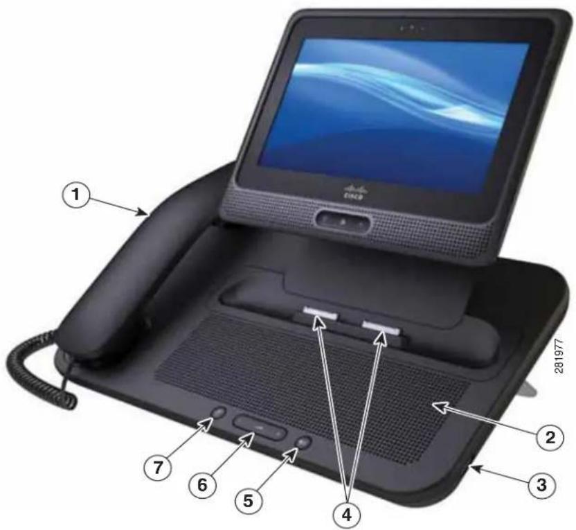
text_image
1 281977 ① ② ③ ④ ⑤ ⑥ ⑦Table 3-2 describes the features on the front of the media station.
Table 3-2 Media Station with Handset Features—Front View
| No. Item No. Item | |||
| 1 Handset 5 Speaker button | |||
| 2 Speaker 6 Volume button | |||
| 3 USB Port 7 Mute button | |||
| 4 Docking ports | |||
Figure 3-2 shows the back view of the media station with handset.
Figure 3-2 Media Station with Handset—Back View
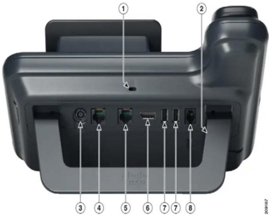
text_image
Diagram of a printer rear panel with numbered ports and connectors, labeled with numbers 1 through 8.Table 3-3 describes the features on the back of the media station.
Table 3-3 Media Station with Handset Features—Back View
| No. Item | No. Item | ||
| 1 Antitheft security lock connector (lock optional) | 5 PC port | ||
| 2 Foot stand 6 DisplayPortTM Connection | |||
| 3 AC power wall plug 7 USB ports | |||
| 4 Network port 8 Handset connection | |||
The USB Serial Console allows a USB port on the media station to be used as a console, eliminating the need for a serial port. Table 3-4 shows the setting for the USB console:
Table 3-4 Terminal Settings for USB Console
| Parameter Setting | |
| Baud rate 115200 | |
| Data 8 bit | |
| Parity | none |
Table 3-4 Terminal Settings for USB Console (continued)
| Parameter Setting | ||
| Stop 1 bit | ||
| Flow control none | ||
| Note | Because Cisco Cius comes preloaded with drivers. Cisco supports only a limited number of cable types. Cisco recommends using IOGEAR USB-serial adapter. | |
| The USB console cable has a USB interface on one end and a serial interface on the other. The USB interface may be plugged in to any of the three USB ports on Cisco Cius. The serial interface connects to the serial port on the PC. | ||
| Tip | If you do not have a serial port on your PC/laptop, two USB console cables can be connected back to back, with a Null modem cable between them. | |
| To use a USB console, use the following procedure. | ||
| Procedure | ||
| Step 1 | In Cisco Unified Communications Manager, set credentials on device page. | |
| Step 2 | Enable “USB debugging” under Product Specific Configuration window. | |
| Step 3 | Connect a USB serial cable to Cisco Cius. Cisco Cius console output appears on your terminal screen. | |
| Step 4 | After output stops, tapto sign in. | |
| Step 5 | Sign in as default using default password. | |
| Step 6 | After $ prompt screen, you can use tools such as debugsh to diagnose Cisco Cius problems. | |
For information on troubleshooting the USCB console, see the "Troubleshooting USB Console" section on page 9-11.
Headsets
Although Cisco performs internal testing of third-party headsets for use with Cisco Cius, Cisco does not certify or support products from headset or handset vendors.
Cisco Cius reduces some background noise that is detected by a headset microphone, but if you want to further reduce the background noise and improve the overall audio quality, use a noise-canceling headset.
Cisco recommends the use of good-quality external devices, for example, headsets that are screened against unwanted radio frequency (RF) and audio frequency (AF) signals. Depending on the quality of headsets and their proximity to other devices such as mobile (cell) phones and two-way radios, some noise or echo may still occur. A hum or buzz may be heard either by the remote party or by both the
remote party and Cisco Cius user. Humming or buzzing sounds can be caused by a range of outside sources; for example, electric lights, electric motors, or large PC monitors. See the “Using External Devices” section on page 3-10, for more information.

In some cases, you can reduce or eliminate hum by using a local power cube or power injector.
These environmental and hardware inconsistencies in the locations where Cisco Cius are deployed means that there is not a single headset solution that is optimal for all environments.
Cisco recommends that customers test headsets in their intended environment to determine performance before making a purchasing decision and deploying them system wide.
Audio Quality Subjective to the User
Beyond the physical, mechanical, and technical performance, the audio portion of a headset must sound good to the user and to the party on the far end. Sound quality is subjective and Cisco cannot guarantee the performance of any headsets. However, a variety of headsets from leading headset manufacturers are reported to perform well with Cisco devices. See manufacturer sites for details.
Wired Headsets
Cisco Cius supports 3.5 mm single plug headsets. To connect a wired headset to Cisco Cius, plug it in to the headset port on the bottom of Cisco Cius to place and answer calls using the headset. Single plug wired headsets may also be plugged into the headset port, located on the left side of the media station.
You can use the wired headset with all of the features on Cisco Cius, including the Volume and Mute buttons. Use these buttons to adjust the earpiece volume and to mute the speech path from the headset microphone.
If the headset is analog, see the for the procedure on configuring the wideband codec.
Bluetooth Wireless Headsets
Cisco Cius supports Bluetooth Version 2.1+EDR technology when the headsets support Bluetooth.
Bluetooth enables low-bandwidth wireless connections within a range of 30 feet (10 meters). The best performance is in the 3- to 6-foot range (1 to 2 meters). You can pair five or more headsets, but only the last one connected is used as the default.
There can be a potential interference issues. Cisco recommends that you reduce the proximity of other 802.11b/g devices, Bluetooth devices, microwave ovens, and large metal objects. If possible, configure other 802.11 devices to use the 802.11a channels.
For a Bluetooth wireless headset to work, it does not need to be within direct line-of-sight of the Cisco Cius tablet, but some barriers, such as walls or doors, and interference from other electronic devices could affect the connection.
Adding a Bluetooth Wireless Headset to Cisco Cius
By default, Bluetooth is enabled for Cisco Cius on the Cisco Unified Communications Manager.

Note
To disable Bluetooth from the Cisco Unified Communications Manager, choose Device > Phone. In the Find and List Phones window, enter the search criteria for the Cisco Cius tablet that you want to modify, and then select Find. On the Product Specific Configuration Layout portion of the Phone Configuration window, scroll down to Bluetooth, click on the Down Arrow and select Disabled.
With Bluetooth enabled on the Cisco Unified Communications Manager, follow these steps to add the headset as an accessory to Cisco Cius:
Procedure
Step 1 Place the headset into discovery/pairing mode.

Note The procedure for placing a headset into discovery/pairing mode is specific to the headset. Please see headset manufacturer's instructions regarding pairing procedure.

Note The headset must be in discovery/pairing mode for Cisco Cius to successfully pair and connect to the device.
Step 2 Enable Bluetooth and Bluetooth settings on Cisco Cius, if they are not already enabled. To verify whether Bluetooth and Bluetooth settings are enabled, from Cisco Cius Main Screen, Press the Menu key and choose Settings > Wireless & networks > Bluetooth settings.

Note You can tell that the Bluetooth wireless headset is enabled if there is a check mark next to "Bluetooth" in the Bluetooth Settings dialog box.

Note If Airplane Mode is enabled, then the Bluetooth and Bluetooth settings are disabled.
Step 3 Select Scan for devices.
After the Bluetooth device is located, its name appears in the window.
Cisco Cius automatically tries to pair with the headset by using a PIN of "0000." If the headset uses a different PIN, enter the correct PIN by referring to the user guide that came with the headset.

Note Cisco recommends that users read the headset user guide for more information about pairing and connecting the headsets.

Note If pairing is unsuccessful, Cisco Cius prompts you to enter the correct PIN.
After Cisco Cius has the correct PIN, it tries to connect to the accessory. Cisco Cius provides feedback to the user while it is trying to connect the accessory. If Cisco Cius cannot connect, it displays an error alert to let the user know the reason for the failure. A timeout of 10 seconds occurs for the Cisco Cius tablet to try to connect the accessory. If the timer expires without a successful connection, an error alert is shown.
Cisco Cius connects with headsets using a shared key authentication and encryption method. Cisco Cius can be connected with five or more headsets at a time. The last one connected is used as the default. Pairing is typically performed once for each headset.
After a device has been paired, its Bluetooth connection is maintained as long as both devices (Cisco Cius and headset) are enabled and within range of each other. The connection typically reestablishes itself automatically if either of the devices powers down and then powers up. However, some headsets require user action to reestablish the connection.
The Bluetooth status indicator indicates whether or not a device is connected.
When headset is out of range from the Cisco Cius, Bluetooth drops the connection after a 15- to 20-second timeout. If the paired headset comes back into range of Cisco Cius (and Cisco Cius is not connected to another Bluetooth headset), the in-range Bluetooth headset automatically reconnects. The user may have to “wake-up” the headset by tapping on its operational button to begin the reconnect process.
If a user is actively on a call using a Bluetooth headset, and the headset is set to off, out-of-range, or is disconnected for any reason, an alert is presented to either continue the call on the speaker/headset or disconnect the call. If no action is taken by the user after 30 seconds, the call is ended.
Removing a Bluetooth Device From the Cisco Cius Tablet
To remove a Bluetooth device from Cisco Cius, follow these steps:
Procedure
Step 1 From the home screen, Press the Menu key and choose Settings > Wireless & networks > Bluetooth settings.
Step 2 Tap Device name.
Step 3 Highlight the device you want to remove and hold that selection until the options appear.
Step 4 Tap Disconnect or Disconnect and Unpair.
Related Documentation About Bluetooth Wireless Headsets
For information about how to use your Bluetooth wireless headset, see:
• Cisco Cius User Guide
- User guide provided with your headset
Advanced Audio Distribution (A2DP) Profile
Cisco Cius supports A2DP streaming audio from a music player to a Bluetooth headset that supports A2DP. A2DP can be disabled by the user. From the Bluetooth devices submenu, select the connected headset and choose Options > Disable A2DP.
Hands-Free Profile
Cisco Cius supports various hands-free profile features that enable you to use hands-free devices (such as Bluetooth wireless headsets) to perform certain tasks without having to handle the Cisco Cius tablet. For example, instead of tapping Redial on Cisco Cius, users can redial a number from their Bluetooth wireless headset according to instructions from the headset manufacturer.
These typical hands-free features apply to Bluetooth wireless headsets that are used with Cisco Cius:
- Ring notification
- Answer a call
- End a call
- Volume control
- Last number redial
- Call waiting notification
- Divert/Reject
• Three-way call handling - Speed dialing
Hands-Free devices may differ in how features are activated. Device manufacturers may also use different terms when referring to the same feature.
For more information, see the manufacturer documentation.
Important Note about Headset Types
Only one headset type works at any given time, so if you have both a Bluetooth headset and an analog headset attached to the Cisco Cius tablet, enabling the Bluetooth headset disables the analog headset. To enable the analog headset, disable the Bluetooth headset.
Using External Devices
Cisco recommends the use of good-quality external devices that are shielded (screened) against unwanted radio frequency (RF) and audio frequency (AF) signals.
Depending on the quality of these devices and their proximity to other devices such as mobile phones or two-way radios, some audio noise may still occur. In these cases, Cisco recommends that you take one or more of the following actions:
- Move the external device away from the source of the RF or AF signals.
- Route the external device cables away from the source of the RF or AF signals.
- Use shielded cables for the external device, or use cables with a better shield and connector.
- Shorten the length of the external device cable.
- Apply ferrites or other such devices on the cables for the external device.
Cisco cannot guarantee the performance of the system because Cisco has no control over the quality of external devices, cables, and connectors. The system performs adequately when suitable devices are attached using good-quality cables and connectors.

In European Union countries, use only external headsets that are fully compliant with EMC Directive 89/336/EC.
Video Displays
Cisco Cius supports external display devices through the micro-HDMI port on the bottom of the tablet. Connect a monitor to the tablet by inserting one end of an HDMI cable into the micro-HDMI port and the other end into a monitor HDMI port.
Installing Cisco Cius
You must connect Cisco Cius to the network and to a power source before using it. Cisco Cius can be powered directly through the AC Adapter on Cisco Cius or through Power over Ethernet (PoE+ 802.3at) through the media station.
Before using external devices, read the “Using External Devices” section on page 3-10 for safety and performance information.

Before you install a Cisco Cius tablet, it must be added to Cisco Unified Communications Manager. For more information, see the “Adding Cisco Cius Tablets to the Cisco Unified Communications Manager Database” section on page 2-8. Make sure you upgrade Cisco Cius to the current firmware image.

Firmware upgrades over the WLAN interface may take longer than upgrading over the wired interface, depending on the quality and bandwidth of the wireless connection. Some upgrades may take more than one hour.
To install Cisco Cius, you must perform the tasks in Table 3-5.
Table 3-5 Installing Cisco Cius
| Task Related Topics | |
| Connect Cisco Cius to external power through the AC adaptor CP-PWR-CUBE 4.(Optional) Connect Cisco Cius to Power over Ethernet (PoE+ 802.3at) through the media station.Note Cisco Cius requires either AC adaptorCP-PWR-CUBE 4 or PoE+ (802.3at) power. With PoE+, media station will be operational.Accessories that are plugged in to the media station, such as mouse or keyboard, will negotiate for power. If not enough power is available for the accessory, an error message will appear on the Cisco Cius screen. | See the Cisco Cius User Guide for information. |
| Charge Cisco Cius. | See the Cisco Cius User Guide for information. |
| Connect a headset to the headset port.(Optional) You can add a headset later if you do not connect one now. | See the Cisco Cius User Guide and the user guide provided with your headset for information. |
| (Optional) Enable Cisco Cius to use the wireless local area network (WLAN). | See the “Configuring Wireless LAN” section on page 4-13 and the “Wireless & Network Settings Menu” section on page 6-2. |
| Configure Network Settings. | See “TFTP Server Settings Menu” section on page 6-3. |
| Configure features. | See the Cisco Cius User Guide for information. |
Related Topics
• Verifying Cisco Cius Startup Process, page 3-12
- Configuring Startup Network Settings, page 3-12
Verifying Cisco Cius Startup Process
After Cisco Cius is charged, press the Power button at the top of the unit to start the tablet. Cisco Cius begins its startup diagnostic process as the tablet checks its hardware. The home screen cycles through two screens, the first displays "Cisco Cius" and the second a flashing blue Cisco logo. The Cisco Cius then boots to the unlock screen with the clock, missed-call calendar and voicemail count icons, and swipe-to-unlock arrow.
If Cisco Cius successfully passes through these stages, it has started up properly. If Cisco Cius does not start up properly, the Cisco Unified Communications Manager will show the tablet as unregistered and and Cisco Cius will display the unregistered icon (red "X") at the top left of the status bar. In addition, when the user opens the phone application, the user will see a message that the tablet is not registered. For information on resolving startup problems, see the "General Troubleshooting" section on page 9-1.
Configuring Startup Network Settings
If you are not using DHCP in your network, you must configure these network settings on Cisco Cius after installing it on the network:
- IP address
- Gateway
- Netmask
- Domain name
• TFTP server IP address
You also may configure the DNS server settings, if necessary.
Collect this information and see the instructions in Chapter 6, "Configuring Settings on Cisco Cius."
Configuring Security on Cisco Cius
The security features protect against several threats, including threats to the identity of Cisco Cius and to data. These features establish and maintain authenticated communication streams between Cisco Cius and the Cisco Unified Communications Manager server, and ensure that Cisco Cius uses only digitally signed files. Data on the Cisco Cius tablet itself is protected by an Encrypted File System.
Cisco Unified Communications Manager (beginning with Release 8.5(1)) includes Security by Default, which provides the following security features for Cisco Cius tablets without running the CTL client:
• Signing of Cisco Cius configuration files
- Cisco Cius configuration file encryption
- HTTPS with Tomcat and other web services

Note
Secure signaling and media features still require you to run the CTL client and use hardware eTokens.
For more information about the security features, see the “Understanding Security Features for Cisco Cius” section on page 1-11. Also, see the Cisco Unified Communications Manager Security Guide.
A Locally Significant Certificate (LSC) is installed on Cisco Cius after you perform the necessary tasks that are associated with the Certificate Authority Proxy Function (CAPF). You can use Cisco Unified Communications Manager Administration to configure an LSC, as described in the Cisco Unified Communications Manager Security Guide.
Alternatively, you can initiate the installation of an LSC from the Enterprise Security Settings menu on Cisco Cius. This menu also lets you update or remove an LSC.
Before You Begin
Make sure that the appropriate Cisco Unified Communications Manager and the CAPF security configurations are complete. See the Cisco Unified Communications Manager Security Guide and the Cisco Cius Wireless LAN Deployment Guide for more information.
To configure an LSC on Cisco Cius, perform these steps:
Procedure
Step 1 Obtain the CAPF authentication code that was set after the CAPF was configured.
Step 2 From the home screen on Cisco Cius, choose Applications Menu > Settings > Location & security > Enterprise security settings.
Step 3 Tap LSC.
Cisco Cius prompts for an authentication string.
Step 4 Enter the authentication string if required by administrator and tap Submit.

Note Cisco Cius restarts after LSC is installed, upgraded, or deleted.
Cisco Cius begins to install, update, or remove the LSC, depending on how the CAPF was configured. During the procedure, a series of messages appears in the LSC option field in the Security Configuration menu, so you can monitor progress. After the procedure is completed successfully, Cisco Cius displays Installed or Not Installed.
The LSC installation, update, or removal process can take a long time to complete. You can stop the process at any time by tapping Cancel.
After the installation procedure is completed successfully, Cisco Cius indicates “Installed.” If Cisco Cius indicates “Not Installed,” the authorization string may be incorrect or Cisco Cius may not be enabled for upgrading. If the CAPF operation deletes the LSC, Cisco Cius indicates “Not Installed” to indicate that the operation was successful. See error messages generated on the CAPF server and take appropriate actions.

natural_image
Portrait of a man sitting on a sofa in an office setting (no visible text or symbols)CHAPTER
4
Understanding the VoIP Wireless Network
This chapter provides an overview of the interaction between Cisco Cius and other key components of a VoIP network in a wireless local area network (WLAN) environment. This chapter contains the following sections:
• Understanding the Wireless LAN, page 4-1
• Understanding WLAN Standards and Technologies, page 4-2
• Bluetooth Wireless Technology, page 4-7
• Components of the VoIP Wireless Network, page 4-7
• Security for Voice Communications in WLANs, page 4-10
- Configuring VoIP WLAN, page 4-12
- Configuring Wireless LAN, page 4-13
Understanding the Wireless LAN
With the introduction of wireless communication, Cisco Cius can provide voice and video communication within the corporate WLAN. Cisco Cius depends on and interacts with wireless access points (APs) and key Cisco IP telephony components, including Cisco Unified Communications Manager, to provide wireless voice communication. Cisco APs can run in standalone or unified mode. Unified mode requires the Cisco Unified Wireless LAN Controller.
Cisco Cius exhibits Wi-Fi capabilities that can use 802.11a, 802.11b, 802.11g, and 802.11n Wi-Fi.
Figure 4-1 shows a typical WLAN topology that enables the wireless transmission of voice for wireless IP telephony.
Figure 4-1 WLAN with Cisco Cius
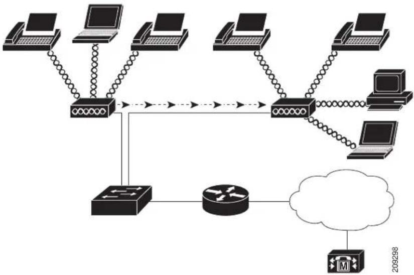
When Cisco Cius powers up, it attempts to associate with remembered networks if it is in range of those networks. If remembered networks are not within range, you can select a broadcasted network or manually add a network. For more information, see Configuring Wireless LAN, page 4-13.
The AP uses its connection to the wired network to transmit data and voice packets to and from the switches and routers. Voice signaling is transmitted to the Cisco Unified Communications Manager server for call processing and routing.
APs are critical components in a WLAN because they provide the wireless links or "hot spots" to the network. Cisco requires that APs supporting voice communications use Cisco IOS Release 12.4(21a)JY. For more information about APs, see the Cisco Cius Wireless LAN Deployment Guide.
Each AP has a wired connection to an Ethernet switch, such as a Cisco 3750 Series, that is configured on a LAN. The switch provides access to gateways and the Cisco Unified Communications Manager server to support wireless IP telephony.
Some networks have wired components that support wireless components. The wired components can comprise switches, routers, and bridges with special modules to enable wireless capability.
For more information about Cisco Unified Wireless Networks, see http://www.cisco.com/en/US/products/hw/wireless/index.html.
Understanding WLAN Standards and Technologies
This section describes the following concepts:
• 802.11 Standards for WLAN Communications, page 4-3
• World Mode (802.11.d), page 4-4
• Radio Frequency Ranges, page 4-5
• 802.11 Data Rates, Transmit Power, Ranges, and Decibel Tolerances, page 4-5
• Wireless Modulation Technologies, page 4-5
• AP, Channel, and Domain Relationships, page 4-6
• WLANs and Roaming, page 4-6
802.11 Standards for WLAN Communications
Wireless LANs must follow the Institute of Electrical and Electronics Engineers (IEEE) 802.11 standards that define the protocols that govern all Ethernet-based wireless traffic. Cisco Cius supports the following standards:
- 802.11a—Uses the 5 GHz band that provides more channels and improved data rates by using Orthogonal Frequency Division Multiplexing (OFDM) technology. Dynamic Frequency Selection (DFS) and Transmit Power Control (TPC) support this standard.
- 802.11b—Specifies the radio frequency (RF) of 2.4 GHz for both transmitting and receiving data at lower data rates (1,2,5.5, 11 Mbps).
- 802.11d—Enables access points to advertise their currently supported radio channels and transmit power levels. The 802.11d-enabled client then uses that information to determine which channels and power levels to use. Cisco Cius requires World Mode (802.11d) to determine which channels are legally allowed for any given country. For supported channels, see Table 4-1. Make sure that 802.11d is properly configured on the Cisco IOS Access Points or Cisco Unified Wireless LAN Controller. For more information, see the “World Mode (802.11.d)” section on page 4-4 and the Cisco Cius Wireless LAN Deployment Guide.
- 802.11e—Defines a set of Quality of Service (QoS) enhancements for Wireless LAN applications.
- 802.11g—Uses the same unlicensed 2.4 GHz band as 802.11b, but extends the data rates to provide greater performance by using OFDM technology. OFDM is a physical-layer encoding technology for transmitting signals by using RF.
- 802.11h—Provides DFS and TPC to the 802.11a Media Access Control (MAC).
- 802.11i—Specifies security mechanisms for wireless networks.
- 802.11n—Uses the radio frequency of 2.4 GHz or 5 GHz for both transmitting and receiving data, and enhances data transfer through the use of multiple input, multiple output (MIMO) technology, channel bonding, and payload optimization.

Note
Cisco Cius has a single antenna and uses the Single Input Single Output (SISO) system, which supports MCS 0 to MCS 7 data rates only (72 Mbps with 20 MHz channels and 150 Mbps 40 MHz channels). MCS 8 to MCS 15 can optionally be enabled if there are 802.11n clients utilizing MIMO technology which can take advantage of those higher data rates.
Table 4-1 lists the supported channels for Cisco Cius.
Table 4-1 Supported Channels for Cisco Cius
| Part Number Band Range | Available Channels | Channel Set |
| — 2.412–2.472 GHz 13 1–13 | ||
| 5.180–5.240 GHz 4 36, 40, 44, 48 | ||
| 5.260–5.320 GHz 4 52, 56, 60, 64 |
Cisco Cius Administration Guide
Table 4-1 Supported Channels for Cisco Cius (continued)
| Part Number Band Range | Available Channels Channel Set |
| 5.500–5.700 GHz 11 100–140 | |
| 5.745–5.825 GHz 5 149, 153, 157, 161, 165 |

Note 802.11j (channels 34, 38, 42, 46) are not supported.
World Mode (802.11.d)
Cisco Cius uses 802.11d to determine which channels and transmit power levels to use and inherits its client configuration from the associated AP. Enable World Mode (802.11d) on the AP to use Cisco Cius in World Mode.
Table 4-2 lists countries and their 802.11d codes that Cisco Cius supports. For more information, see the Cisco Cius Wireless LAN Deployment Guide.
Table 4-2 Countries That Cisco Cius Supports
| Argentina (AR) India (IN) Poland | (PL) | |
| Australia (AU) | Indonesia (ID) | Portugal (PT) |
| Austria (AT) | Ireland (IE) | Puerto Rico (PR) |
| Belgium (BE) | Israel (IL) | Romania (RO) |
| Brazil (BR) | Italy (IT) | Russian Federation (RU) |
| Bulgaria (BG) | Japan (JP) | Saudi Arabia (SA) |
| Canada (CA) | Korea (KR / KP) | Singapore (SG) |
| Chile (CL) | Latvia (LV) | Slovakia (SK) |
| Colombia (CO) | Liechtenstein (LI) | Slovenia (SI) |
| Costa Rica (CR) | Lithuania (LT) | South Africa (ZA) |
| Cyprus (CY) | Luxembourg (LU) | Spain (ES) |
| Czech Republic (CZ) | Malaysia (MY) | Sweden (SE) |
| Denmark (DK) | Malta (MT) | Switzerland (CH) |
| Estonia (EE) | Mexico (MX) | Taiwan (TW) |
| Finland (FI) | Monaco (MC) | Thailand (TH) |
| France (FR) | Netherlands (NL) | Turkey (TR) |
| Germany (DE) | New Zealand (NZ) | Ukraine (UA) |
| Gibraltar (GI) | Norway (NO) | United Arab Emirates (AE) |
| Greece (GR) | Oman (OM) | United Kingdom (GB) |
| Hong Kong (HK) | Panama (PA) | United States (US) |
Table 4-2 Countries That Cisco Cius Supports (continued)
| Hungary (HU) Peru (PE) Venezuela (VE) | |
| Iceland (IS) Philippines (PH) Vietnam (VN) |
For the Cisco Unified Wireless LAN Controller, World Mode is enabled automatically when a country code is entered. See the "802.11d" section in Cisco Cius Wireless LAN Deployment Guide for the proper country code. For Cisco Autonomous Access Points, World Mode must be enabled manually. Use the following commands:
Interface dot11radio X
world-mode dot11d countryUS both

For 2.4 GHz radio, enter 0 for X in the Interface Command field. For 5 GHz radio, enter 1 for X.
For more information, see the “Models and Localization” section in Cisco Cius Wireless LAN Deployment Guide.
Radio Frequency Ranges
WLAN communications use the following radio frequency ranges:
- 2.4 GHz—Many devices that use 2.4 GHz can potentially interfere with the 802.11b/g connection. An interferer can produce a Denial of Service (DoS) scenario, possibly preventing successful 802.11 transmissions.
- 5 GHz—The 5 GHz frequency provides more channels and has less interferers than the 2.4 GHz frequency. It is divided into several sections called Unlicensed National Information Infrastructure (UNII) bands, each with four channels. The channels are spaced at 20 MHz.
802.11 Data Rates, Transmit Power, Ranges, and Decibel Tolerances
See the “Radio Characteristics” section in the Cisco Cius Wireless LAN Deployment Guide for Transmit (Tx) power capacities, data rates, ranges in feet and meters, and decibels tolerated by the receiver by 801.11 standard.
Wireless Modulation Technologies
Wireless communications use the following modulation technologies for signaling:
- Direct-Sequence Spread Spectrum (DSSS)—Prevents interference by spreading the signal over the frequency range or bandwidth. DSSS technology multiplexes chunks of data over several frequencies so that multiple devices can communicate without interference. Each device has a special code that identifies its data packets and all others are ignored. Cisco wireless 802.11b/g products use DSSS technology to support multiple devices on the WLAN.
- Orthogonal Frequency Division Multiplexing (OFDM)—Transmits signals by using RF. OFDM is a physical-layer encoding technology that breaks one high-speed data carrier into several lower-speed carriers to transmit in parallel across the RF spectrum. OFDM, when used with 802.11g and 802.11a, can support data rates as high as 54 Mbps.
Table 4-3 provides a comparison of data rates, number of channels, and modulation technologies by IEEE standard.
Table 4-3 Data Rates, Number of Channels, and Modulation Technologies by IEEE Standard
| Item 802.11b 802.11g 802.11a 802.11n | ||||
| Data Rates 1, 2,5.5,11 Mbps | 6, 9, 12, 18, 24,36, 48,54 Mbps | 6, 9, 12, 18, 24,36, 48,54 Mbps | • 20 MHz Channels:7–72 Mbps• 40 MHz Channels:15–150 Mbps | |
| Channels | 13 | 13 | 24 | 13 or 24 |
| Wireless Modulation | DSSS | OFDM | OFDM | OFDM |
AP, Channel, and Domain Relationships
APs transmit and receive RF signals over channels within the 2.4 GHz or 5 GHz frequency band. To provide a stable wireless environment and reduce channel interference, you must specify nonoverlapping channels for each AP. The recommended channels for 802.11b and 802.11g in North America are 1, 6, and 11.

In a noncontroller-based wireless network, Cisco recommends that you statically configure channels for each AP. Some channels may need to be statically configured if there is an intermittent interferer to avoid disruptions in that area. If your wireless network uses a controller, use the Auto-RF feature with minimal voice disruption.
For more information about APs, see the "Configuring VoIP WLAN" section on page 4-12.
For more information about AP, channel, and domain relationships, see the “Designing the Wireless LAN for Voice” section in the Cisco Cius Wireless LAN Deployment Guide.
WLANs and Roaming
For information about WLANs and roaming for Cisco Cius, see "Cisco Fast Roaming Application Note" at:
http://www.cisco.com/en/US/products/hw/wireless/ps4570/prod_technical_reference09186a00801c5223.html and the "Roaming" section of the Cisco Cius Wireless LAN Deployment Guide.
Related Topics
• Voice QoS in a Wireless Network, page 4-8
- Configuring VoIP WLAN, page 4-12
Bluetooth Wireless Technology
Bluetooth enables low-bandwidth wireless connections within a range of 30 feet (10 meters). The best performance is in the 3-to 6-foot (1- to 2-meter) range. Bluetooth wireless technology operates in the 2.4 GHz band which is the same as the 802.11b/g/n band. There can be a potential interference issues with Bluetooth devices, microwave ovens, cordless phones, and large metal objects; therefore, Cisco recommends that you use 802.11a or 802.11.n that operates in the 5 GHz band.
For more information about configuring Bluetooth on Cisco Cius, see the Bluetooth Settings Menu Options, page 6-8. For more information about using Bluetooth headsets with your Cisco Cius, see Hands-Free Profile, page 3-10 and the “Bluetooth Configuration” section of the Cisco Cius Wireless LAN Deployment Guide.
Components of the VoIP Wireless Network
Cisco Cius must interact with several network components in the WLAN to place and receive calls successfully. The following topics describe network components:
• Interacting with Cisco Unified Wireless APs, page 4-7
• Associating to APs, page 4-8
• Voice QoS in a Wireless Network, page 4-8
• Interacting with Cisco Unified Communications Manager, page 4-10
Interacting with Cisco Unified Wireless APs
Cisco Cius uses the same APs as wireless data devices. However, voice traffic over a WLAN requires different equipment configurations and layouts than a WLAN that is used exclusively for data traffic. Data transmission can tolerate a higher level of RF noise, packet loss, and channel contention than voice transmission. Packet loss during voice transmission can cause choppy or broken audio and make the phone call inaudible. Packet errors can also cause blocky or frozen video.
Because Cisco Cius users move from location to location, RF coverage needs to include stairwells, elevators, quiet corners, outside conference rooms, and passageways. To ensure good voice quality and optimal RF signal coverage, you must perform a site survey. The site survey determines what AP platform, antenna type, AP placement, Tx power levels, channel, and data rates are best for this environment. Ensure that all required areas are surveyed so adequate coverage is provided.
After deploying and using wireless voice, continue to perform postinstallation site surveys. When you add a group of new users, install more equipment, or stack large amounts of inventory, you are changing the wireless environment. A postinstallation survey verifies that the AP coverage is still adequate for optimal voice communications.

Packet loss can occur during roaming; however, the security mode and the presence of fast roaming depicts how much packet loss occurs during transmission. Cisco recommends implementing Cisco Centralized Key Management (CCKM) to enable fast roaming.
For more information about Voice QoS in a wireless network, see the “Voice QoS in a Wireless Network” section on page 4-8 and the “Quality of Service (QoS)” section of Cisco Cius Wireless LAN Deployment Guide.
Associating to APs
At startup, Cisco Cius scans the channels for remembered profiles. Cisco Cius performs active scans (for remembered profiles) and passive scans (for broadcasted WLANs). Cisco Cius uses the Received Signal Strength Indicator (RSSI) variable to determine the best AP. RSSI measures the signal strength of available APs within the RF coverage area. Cisco Cius attempts authentication to a frequency band based on the 802.11 mode configuration for the discovered WLAN:
- Auto—Cisco Cius connects to the AP with the highest RSSI value
• 5 GHz—Cisco Cius associates with 5 GHz channels - 2.4 GHz—Cisco Cius associates with 2.4GHz channels
Cisco Cius associates with the AP with the highest RSSI that has matching SSID and encryption types. To ensure that voice traffic is handled properly, you must configure the correct QoS in the AP.
Related Topics
• Security for Voice Communications in WLANs, page 4-10
- Configuring VoIP WLAN, page 4-12
Voice QoS in a Wireless Network
Voice and video traffic on the Wireless LAN, like data traffic, is susceptible to delay, jitter, and packet loss. These issues do not impact the data user, but have serious implications for a voice call. To ensure that voice traffic receives timely and reliable treatment with low delay and low jitter, you must implement QoS and use separate virtual LANs (VLANs) for voice/video and data. By isolating the voice and video traffic onto a separate VLAN, you can use QoS to provide priority treatment for voice and video packets when they travel across the network. Also, use a separate VLAN for data traffic, not the default native VLAN, which is typically used for all network devices.
Cisco recommends the following VLANs on the network switches and the APs that support voice and video connections on the WLAN:
- Voice/Video VLAN—Voice traffic to and from Cisco Cius
- Data VLAN—Data traffic to and from other wireless devices
- Native VLAN—AP management
Assign separate SSIDs to the voice/video and to the data VLANs. If you configure a separate management VLAN in the WLAN, do not associate an SSID with the management VLAN.
By separating Cisco Cius tablets into a voice VLAN and marking voice packets with higher QoS, you can ensure that voice traffic gets priority treatment over data traffic, resulting in lower packet delay and fewer lost packets.
Unlike wired networks with dedicated bandwidths, traffic direction is important for wireless LANs when implementing QoS. Traffic is classified as upstream or downstream from the AP as shown in Figure 4-2.
Figure 4-2 Voice Traffic in a Wireless Network
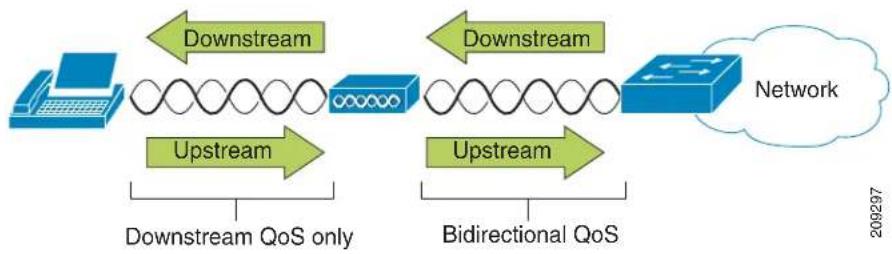
flowchart
graph LR
    A["Laptop"] -->|Downstream| B["Router"]
    B -->|Upstream| C["Network"]
    B -->|Downstream| D["Router"]
    D -->|Upstream| C
    style A fill:#333,stroke:#fff,color:#fff
    style B fill:#333,stroke:#fff,color:#fff
    style C fill:#333,stroke:#fff,color:#fff
    style D fill:#333,stroke:#fff,color:#fff
Beginning with Cisco IOS release 12.2(11)JA, Cisco Aironet APs support the contention-based channel access mechanism called Enhanced Distributed Coordination Function (EDCF). The EDCF type of QoS has up to eight queues for downstream (toward the 802.11b/g clients) QoS. You can allocate the queues based on these options:
• Differentiated Services Code Point (DSCP) settings for the packets
- Layer 2 or Layer 3 access lists
• VLANs for specific traffic
• Dynamic registration of devices
Although you can have up to eight queues on the AP, Cisco recommends that you use only two queues for voice traffic to ensure the best possible voice QoS. Place voice (RTP) and signaling (SIP) traffic in the highest-priority queue, and place data traffic in a best-effort queue. Although 802.11b/g EDCF does not guarantee that voice traffic is protected from data traffic, you get the best statistical results by using this queuing model. The queues are:
- Best Effort (BE)—0, 3
- Background (BK)—1, 2
• Video (VI)—4, 5 - Voice (VO)—6, 7

Call Control (SIP) is sent as UP4 (VI). Video is sent as UP5 (VI) when Admission Control Mandatory (ACM) is disabled for video (Traffic Specification [TSpec] disabled). Voice is sent as UP6 (VO) when ACM is disabled for voice (TSpec disabled).
Table 4-4 provides a QoS profile on the AP giving priority to voice, video, and call control (SIP) traffic.
Table 4-4 QoS Profile and Interface Settings
| Traffic Type | DSCP | 802.1p | WMM UP | Port Range |
| Voice | EF (46) | 5 | 6 | UDP 16384-32677 |
| Interactive Video | AF41 (34) | 4 | 5 | UDP 16384-32677 |
| Call Control | CS3 (24) | 3 | 4 | TCP/UDP 5060-5061 |
To improve reliability of voice transmissions, Cisco Cius supports the IEEE 802.11e industry standard and is Wi-Fi Multimedia (WMM) capable. WMM enables differentiated services for voice, video, best-effort data, and other traffic. However, in order for these differentiated services to provide sufficient
QoS for voice packets, only a certain amount of voice bandwidth can be serviced or admitted on a channel at one time. If the network can handle "N" voice calls with reserved bandwidth, when the amount of voice traffic is increased beyond this limit (to N+1 calls), the quality of all calls suffers.
To help address the problems of VoIP stability and roaming, an initial Call Admission Control (CAC) scheme is required. With SIP CAC enabled on the WLAN, QoS is maintained in a network overload scenario by ensuring that the number of active voice calls does not exceed the configured limits on the AP. During times of network congestion, the system maintains a small bandwidth reserve so wireless phone clients can roam into a neighboring AP, even when the AP is at “full capacity.” After reaching the voice bandwidth limit, the next call is load-balanced to a neighboring AP without affecting the quality of the existing calls on the channel.
Implementing QoS in the connected Ethernet switch is highly desirable to maintain good voice quality. The Class of Service (COS) and DSCP values that Cisco Cius sets do not need to be modified.

The DSCP, COS and WMM UP markings correctly display for the optimum transmission of video frames. Cisco Cius does not support Voice and Video CAC; Cisco recommends that you implement SOP CAC.
Related Topics
• Interacting with Cisco Unified Communications Manager, page 4-10
• Authentication Methods, page 4-11
- Configuring VoIP WLAN, page 4-12
Interacting with Cisco Unified Communications Manager
Cisco Unified Communications Manager is the call control component in the network that handles and routes calls for the wireless IP phones, including Cisco Cius. Cisco Unified Communications Manager manages the components of the IP telephony system—Cisco Cius tablets, access gateways, and the resources—for such features as call conferencing and route planning. When deploying Cisco Cius on a wireless LAN, you must use Cisco Unified Communications Manager Release 8.5 or later and the SIP protocol.
Before Cisco Unified Communications Manager can recognize a Cisco Cius tablet, it must register with Cisco Unified Communications Manager and be configured in the database. For information about setting up Cisco Cius in Cisco Unified Communications Manager, see the “Configuring Cisco Cius in Cisco Unified Communications Manager” section on page 1-20 and the “Configuring Product-Specific Options” section on page 5-8.
You can find more information about configuring Cisco Unified Communications Manager to work with Cisco Cius and IP devices in the Cisco Unified Communications Manager Administration Guide, Cisco Unified Communications Manager System Guide, and Cisco Cius Wireless LAN Deployment Guide.
Security for Voice Communications in WLANs
Because all WLAN devices that are within range can receive all other WLAN traffic, securing voice communications is critical in WLANs. To ensure that voice traffic is not manipulated or intercepted by intruders, Cisco Cius and Cisco Aironet APs are supported in the Cisco SAFE Security architecture. For more information about security in networks, See
http://www.cisco.com/en/US/netsol/ns744/networking_solutions_program_home.html.
This section contains the following items:
• Authentication Methods, page 4-11
• Encryption Methods, page 4-11
- Choosing AP Authentication and Encryption Methods, page 4-12
Authentication Methods
The Cisco Wireless IP telephony solution provides wireless network security that prevents unauthorized sign-in and compromised communications by using the following authentication methods:
• WPA (Wi-Fi Protected Access)
• WPA2 (Wi-Fi Protected Access 2)
• WPA-PSK (Wi-Fi Protected Access-Pre-Shared Key)
• WPA2-PSK (Wi-Fi Protected Access 2-Pre-Shared Key)

Note WPA2-PSK appears as WPA/WPA2-PSK on Cisco Cius.
- EAP-FAST (Extensible Authentication Protocol–Flexible Authentication via Secure Tunneling)
- PEAP (Protected Extensible Authentication Protocol)

Note EAP-FAST and PEAP are the 802.x options when choosing WPA/WPA2 via 802.1x EAP selection.
• CCKM (Cisco Centralized Key Management)

Note CCKM can be optionally used with WPA/WPA2.
• WEP (Wired Equivalent Protocol)
- Open
For more information about authentication methods, see the “Wireless Security” section in the Cisco Cius Wireless LAN Deployment Guide.
Encryption Methods
To ensure that voice traffic is secure, Cisco Cius supports the following encryption methods:
• AES (Advanced Encryption Scheme)
- TKIP/MIC (Temporal Key Integral Protocol/Message Integrity Check)
• WEP (Wired Equivalent Protocol) 40/64 and 104/128 bit
For more information about encryption methods, see the “Wireless Security” section in the Cisco Cius Wireless LAN Deployment Guide.
Choosing AP Authentication and Encryption Methods
See the “Wireless Security” section in the Cisco Cius Wireless LAN Deployment Guide for a list of authentication and encryption schemes that Cisco Cius supports.
Related Topics
• Interacting with Cisco Unified Wireless APs, page 4-7
• Authentication Methods, page 4-11
• Encryption Methods, page 4-11
• Interacting with Cisco Unified Communications Manager, page 4-10
• Components of the VoIP Wireless Network, page 4-7
- Configuring VoIP WLAN, page 4-12
Configuring VoIP WLAN
This section provides configuration guidelines for deploying Cisco Cius in the WLAN and contains these topics:
• Supported Access Points, page 4-12
• Supported APs and Modes, page 4-12
• Supported Antennas, page 4-13
Supported Access Points
Cisco Cius is supported on both the Cisco autonomous and unified solutions. Minimum and recommended versions are:
• Cisco IOS Access Points (Autonomous)
- Minimum = 12.4(21a)JY
- Recommended = 12.4(25d)JA or later
• Cisco Unified Wireless LAN Controller
- Minimum = 6.0.202.0
- Recommended = 7.0.116.0 or later
See the “Wireless Security” section in the Cisco Cius Wireless LAN Deployment Guide for current AP recommendations.
Supported APs and Modes
See the “Wireless Security” section in the Cisco Cius Wireless LAN Deployment Guide for current AP recommendations.

Note
Voice over the Wireless LAN (VoWLAN) via Outdoor MESH technology (Cisco 1500 Series) is not supported.
Cisco Cius Administration Guide
Third-party access points are not fully supported or certified because no testing is performed to guarantee interoperability. However, if the access point is Wi-Fi compliant, basic interoperability should be available. Some features, such as CCX, and other key features, such as WMM, Unscheduled Auto Power Save Delivery (U-APSD), Dynamic Transmit Power Control (DTPC), proxy ARP, 802.11d, 802.11e, 802.11i, 802.11h, and CCKM may not be available.
Supported Antennas
See the “Supported Antennas” section in the Cisco Cius Wireless LAN Deployment Guide for a list of supported antennas.
Configuring Wireless LAN
Ensure that the Wi-Fi coverage in the location where the wireless is deployed is suitable for transmitting video and voice packets. See the Cisco Cius Wireless LAN Deployment Guide, which includes the following configuration sections:
- Configuring Cisco Unified Communications Manager
- Configuring the Cisco Wireless LAN Controller and Access Points
- Configuring Cisco Cius
Before Cisco Cius can connect to the WLAN, you must configure the network profile for Cisco Cius with the appropriate WLAN settings. You can use the Network Setup menu on Cisco Cius to access the WLAN Setup submenu and set up the WLAN configuration. For instructions, see the “Wireless & Network Settings Menu” section on page 6-2.
For information regarding troubleshooting WLAN, see the “Troubleshooting WLAN” section on page 9-11.
Configuring Wireless LAN

natural_image
Portrait of a man sitting on a sofa in an office setting (no visible text or symbols)CHAPTER
Configuring Features, Templates, Services, and Users
After you install Cisco Cius tablets in your network, configure their network settings, and add them to Cisco Unified Communications Manager, you must use Cisco Unified Communications Manager Administration to configure telephony features, optionally modify phone templates, set up services, and assign users.
This chapter provides an overview of these configuration and setup procedures. Cisco Unified Communications Manager Administration documentation provides detailed instructions for these procedures.
For suggestions about how to provide users with information about features and what information to provide, see Appendix A, "Providing Information to Users Through a Website."
For information about setting up Cisco Cius tablets in non-English environments, see Appendix B, "Supporting International Users."
This chapter contains following topics:
• Telephony Features Available for Cisco Cius, page 5-2
- Configuring Product-Specific Options, page 5-8
• Modifying Phone Button Templates, page 5-23
- Configuring Feature Control Policies, page 5-23
- Configuring Reset Options/Load Upgrades, page 5-24
- Adding Users to Cisco Unified Communications Manager, page 5-25
• Managing the User Options Web Pages, page 5-25
Telephony Features Available for Cisco Cius
After you add a Cisco Cius to Cisco Unified Communications Manager, you can add functionality to the Cisco Cius. Table 5-1 includes a list of supported telephony features, many of which you can configure using Cisco Unified Communications Manager Administration. The Reference column lists Cisco Unified Communications Manager and other documentation that contains configuration procedures and related information.
For more information about using these features, see the Cisco Cius User Guide.

Note
Cisco Unified Communications Manager Administration also provides several service parameters that you can use to configure various telephony functions. For more information about accessing and configuring service parameters, see the Cisco Unified Communications Manager Administration Guide. For more information about the functions of a service, click on the name of the parameter or the question mark help button in the Service Parameter Configuration window.
Table 5-1 Telephony Features for Cisco Cius
| Feature Description | Configuration Reference | |
| All Calls Allows a user | to view a list of active and held calls, sorted in chronological order (oldest first), and incoming and completed calls, sorted newest to oldest | ·For more information, see the Cisco Cius User Guide.·Requires no configuration. |
| Auto Dial Allows the | Cisco Cius user to choose from matching numbers in the Recent Call History, which includes placed, received and missed calls. To place the call, the user can choose a number from any of these call lists or continue to enter digits manually. | Requires no configuration. |
| Barge Allows a user to join a nonprivate call on a shared phone line. Barge features adds a user to a call and converts it into a conference, allowing the user and other parties to access conference features.Note Cisco Cius can still use barge after the Built In Bridge Enable service parameter is set to off. To prevent a user from using the Barge feature on Cisco Cius, you must disable Barge in Feature Control Policy for the Cisco Cius tablet. | Note Cisco Cius can still use barge after the Built In Bridge Enable service parameter is set to off. To prevent a user from using the Barge feature on Cisco Cius, you must disable Barge in Feature Control Policy for the Cisco Cius tablet. | For more information, see:·Cisco Unified Communications Manager Administration Guide, “Cisco Unified IP Phone Configuration” chapter.·Cisco Unified Communications Manager System Guide, “Cisco Unified IP Phone” chapter.·Cisco Unified Communications Manager Features and Services Guide, “Barge and Privacy” chapter.·Cisco Unified Communications Manager Administration Guide, “Feature Control Policy Configuration” chapter. |
| Busy Lamp Field (BLF) | Allows a user to monitor the call state of a directory number associated with a speed-dial button, call log, or directory listing on Cisco Cius. | For more information, go to the “Presence” chapter in the Cisco Unified Communications Manager Features and Services Guide. |
| Feature | Description | Configuration |
| Call Forward Allows | users to redirect incoming calls to another number. Call forward options include Call Forward All, Call Forward Busy, Call Forward No Answer, and Call Forward No Coverage.Additional options include allowing calls that are placed from target number to ring through rather than be forwarded and preventing a call-forward loop from exceeding the maximum number of links in a call-forwarding chain.Call forward options can be assigned on a per-line basis. | For more information, see:Cisco Unified Communications Manager Administration Guide, “Directory Number Configuration” chapter.Cisco Unified Communications Manager System Guide, “Cisco Unified IP Phone” chapter.“Managing the User Options Web Pages” section on page 5-25 |
| Calling Line Identification (CLID) | Allows a user to enable the full, external number to be used for calling line identification. | For more information, see the “Cisco Unified IP Phone” chapter in the Cisco Unified Communications Manager System Guide. |
| Calling Line Identification Presentation (CLIP/CLIR) | Allows a user to enable or restrict the originating caller number on a case-by-case basis. | For more information, see the “Cisco Unified IP Phone” chapter in the Cisco Unified Communications Manager System Guide. |
| Conference • Allows | a user to talk simultaneously with multiple parties by calling each participant individually.Allows any participant in a standard (ad hoc) conference to add or remove participants.Allows users to join two or more calls that are on one line to create a conference call and remain on the call. | The service parameter Advance Adhoc Conference (disabled by default in Cisco Unified Communications Manager Administration) allows you to enable these features.For information about conferences, go to the “Conference Bridges” chapter in the Cisco Unified Communications Manager System Guide.For more information, see the “Cisco Unified IP Phone” chapter in the Cisco Unified Communications Manager System Guide.Note Be sure to inform your users whether these features are activated. |
| Divert After Enhanced | Immediate Divert is enabled, it allows users to divert incoming calls directly to their voice messaging system. | For more information about diverting calls to voicemail, go to the “Immediate Divert” chapter in the Cisco Unified Communications Manager Features and Services Guide.For more information about Enhanced Immediate Divert, see the “Cisco Unified IP Phone” chapter in the Cisco Unified Communications Manager System Guide. |
| Dock/Undock Allows | a user to continue a call that was initiated when the Cisco Cius tablet was docked when the user undocks the tablet. | Cisco Cius User Guide |
| Do Not Disturb (DND) | When DND is turned on, either no audible rings occur during the ringing-in state of a call, or no audible or visual notifications of any type occur.Note DND does not affect 911 calls.You can configure Cisco Cius to have a phone-button template with DND as one of the selected features.The following DND-related parameters are configurable in Cisco Unified Communications Manager Administration:Do Not Disturb—This check box allows you to enable DND on a per-tablet basis. Choose Cisco Unified Communications Manager Administration > Device > Phone > Phone Configuration.DND Incoming Call Alert—Choose the type of alert to play, if any, on a Cisco Cius for incoming calls when DND is active. This parameter is located on both the Common Phone Profile window and the Phone configuration window (Phone Configuration window value takes precedence).BLF Status Depicts DND—Enables DND status to override busy/idle state. | For more information, go to the “Do Not Disturb” chapter in the Cisco Unified Communications Manager Features and Services Guide. |
| Hold Status Enables C | Cisco Cius tablets with a shared line to distinguish between the local and remote lines that placed a call on hold. | No configuration is required. |
| Hold/Resume Allows | the user to move a connected call from an active state to a held state.To place a call on hold, tap the Hold button. To resume a call, choose the line with the held call and tap the Hold button. | Requires no configuration, unless you want to use music on hold. See “Music-on-Hold” in this table for information. |
| Ignore Allows a user | to ignore an incoming call from the notification window. | No configuration is required. |
| Message Waiting Indicator | A light on the media station handset that indicates that a user has one or more new voice messages. | For more information see:Cisco Unified Communications Manager Administration Guide, “Message Waiting Configuration” chapter.Cisco Unified Communications Manager System Guide, “Voice Mail Connectivity to Cisco Unified Communications Manager” chapter. |
| Music On Hold | Plays music while callers are on hold. | For more information see the “Music On Hold” chapter in the Cisco Unified Communications Manager Features and Services Guide. |
| Mute Mutes the audio | input for all input devices including, bluetooth and 3.5 mm handsets, media station and tablet speakers, and headset. | Requires no configuration. |
| Plus Dialing Allows the user to dial E.164 numbers prefixed with a “+” sign.To dial the + sign, the user needs to press and hold the “*” key for at least 1 second. This applies to dialing the first digit for an on-hook or off-hook call only. | Requires no configuration. | |
| Protected Calling | Provides a secure (encrypted) connection between two Cisco Cius tablets or a Cisco Cius and IP phone. A security tone is played at the beginning of the call to indicate that both devices are protected. Some features, such as conference calling, shared lines, and Join Across Lines are not available when protected calling is configured. Protected calls are not authenticated. | For more information about security, see the “Overview of Supported Security Features” section on page 1-13.For additional information, see the Cisco Unified Communications Manager Security Guide. |
| Ringtone Setting | Identifies ring type used for a line when Cisco Cius has another active call. | For more information, see the Cisco Unified Communications Manager Administration Guide, “Directory Number Configuration” chapter. |
| Ringtone Users can customize how their Cisco Cius indicates an incoming call and a new voice message. | For more information, see the Cisco Cius User Guide. | |
| Secure and Nonsecure Indication Tone | After a Cisco Cius is configured as secure (encrypted and trusted) in Cisco Unified Communications Manager, it can be given a “protected” status. After that, if desired, the protected device can be configured to play an indication tone at the beginning of a call:• Protected Device—To change the status of a secure Cisco Cius to protected, check the “Protected Device” check box in Cisco Unified Communications Manager Administration > Device > Phone > Phone Configuration.• Play Secure Indication Tone—To enable the protected Cisco Cius to play a secure or nonsecure indication tone, set the “Play Secure Indication Tone” to True. (The default is False.) You set this option in Cisco Unified Communications Manager Administration> System > Service Parameters. Select the server and then the Unified CM service. In the Service Parameter Configuration window, select the option in the Feature - Secure Tone area. (The default is False.)Only protected Cisco Cius tablets hear these secure or nonsecure indication tones. (Nonprotected devices never hear tones.) If the overall call status changes during the call, the indication tone changes accordingly. At that time, the protected device plays the appropriate tone.A protected device plays or does not play a tone under these circumstances:• After the option to play the tone is enabled, Play Secure Indication Tone option is enabled (True):- When end-to-end secure media is established and the call status is secure, Cisco Cius plays the secure indication tone (three long beeps with pauses).- After end-to-end nonsecure media is established and the call status is nonsecure, Cisco Cius plays the nonsecure indication tone (six short beeps with brief pauses).• If the Play Secure Indication Tone option is disabled, no tone is played. | Requires no configuration. |
| Secure Conference | Allows secure Cisco Cius tablets to place conference calls using a secure conference bridge.As new participants are added, the secure call icon is displayed as long as all participants use secure devices.The Conference List indicates the security level of each conference participant. Initiators can remove nonsecure participants from the Conference List. (Any participant can add or remove conference participants if the Advanced Adhoc Conference Enabled parameter is set.) | For more information about security, see the “Overview of Supported Security Features” section on page 1-13.For additional information, see:Cisco Unified Communications Manager System Guide, “Conference Bridges” chapterCisco Unified Communications Manager Administration Guide, “Conference Bridge Configuration” chapterCisco Unified Communications Manager Security Guide. |
| Shared Line Allows a user to have multiple Cisco Cius tablets that share the same phone number or allows a user to share a phone number with a coworker. | For more information, see the “Understanding Directory Numbers” chapter in the Cisco Unified Communications Manager System Guide. | |
| Speed Dial Allows a user to configure speed dial to a specific destination directory number. | — | |
| Transfer Allows users to redirect connected calls from their Cisco Cius tablet to another number.The user can connect two calls to each other. The user can remain on the line or transfer the call without staying on line. | Requires no configuration. | |
| Unified Mobility Allows users to extend call control capabilities of Cisco Unified Communications Manager from the primary workplace desk phone of a mobile worker to any location or device of their choosing. | For more information see the “Cisco Unified Mobility” chapter in the Cisco Unified Communications Manager Features and Services Guide. | |
| Voice Messaging System | Enables callers to leave messages if calls are unanswered. | For more information see:Cisco Unified Communications Manager Administration Guide, “Cisco Voice-Mail Port Configuration” chapter.Cisco Unified Communications Manager System Guide, “Voice Mail Connectivity to Cisco Unified Communications Manager” chapter.“Configuring Visual Voicemail” section on page 5-18. |
Configuring Product-Specific Options
Cisco Unified Communications Manager Administration allows you to set some product-specific configuration parameters for Cisco Cius in any of the following windows:
- Enterprise Phone Configuration window (System > Enterprise Phone Configuration)
- Common Phone Profile window (Device > Device Settings > Common Phone Profile); Product Specific Configuration Layout portion of window
- Device Phone Configuration window (Device > Phone > Add New > Cius); Product Specific Configuration Layout portion of window
Table 5-2 shows the Product Specific Configuration options.
Table 5-2 Cisco Cius Product Specific Configuration Options
| Feature Description Default | ||
| Disable USB Disables the | USB ports on the device and media station. | False. |
| SDIO Indicates whether the | SDIO device on the device is enabled or disabled. | Disabled. |
| Bluetooth | Indicates whether the Bluetooth service on the Cisco Cius tablet can or cannot be enabled. | Enabled. |
| Days Display Not Active | Allows the user to specify the days that the backlight is to remain off by default. | Typically this would be Saturday and Sunday for U.S. corporate customers.Note The list contains all of the days of the week. To turn off backlight on Saturday and Sunday hold down Control and select Saturday and Sunday. |
| Display On Time Indicates | the time of day the display is to automatically turn itself on for days listed in the off schedule. | 07:30.Maximum length: 5.Note Enter value in a 24-hour format, where 0:00 is the beginning of the day and 23:59 is the end of the day. |
| Display On Duration | Indicates the amount of time the display is to be active when it is turned on by the programmed schedule. | 10:30.Maximum length: 5.Note Maximum value is 24 hours. This value is in hours and minutes format. “1:30” would activate the display for 1 hour and 30 minutes. |
| Display Idle Timeout Indicates how long to wait before the display is turned off when it was turned on by user activity. | 01:00Maximum length: 5Note Maximum value is 24 hours. This value is in hours and minutes format. “1:30” would turn off the display after 1 hour and 30 minutes of inactivity.For more information, see the “Configuring Screen Lock and Display Idle Time Out” section on page 5-20. | |
| Display On When Incoming Call | When the device is in screen saver mode, this will turn the display on when a call is ringing. | Enabled. |
| RTCP Maintains statistic for audio.Also used for lip sync in video calls. | Disabled. | |
| Advertise G.722 and iSAC Codecs | Indicates whether the phone application will advertise the wideband codecs to the Cisco Unified Communications Manager.Code negotiation involves two steps:1. The phone application must advertise the supported codecs to the Cisco Unified Communications Manager.2. When the Cisco Unified Communications Manager gets the list of supported codecs from all phones involved in the call attempt, it chooses a commonly supported codec based on various factors, including the region pair setting. | Use System DefaultValid values:System Default—Phone application will defer to the setting specified in the enterprise parameter, Advertise G.722 and iSAC Codecs Cooperative—Phone application will not advertise the wideband codecs to the Cisco Unified Communications Manager.Enabled—Phone application will advertise the wideband codecs to the Cisco Unified Communications Manager. |
| Video Calling When enabled | indicates that the device will participate in video calls. | Enabled. |
| Wifi Indicates whether the | Wi-Fi on the device is enabled or disabled. | Enabled.Note For the Enterprise and Common settings, the Wifi parameter is set at the default value (enabled) and the “Override Common Settings” check box is checked.Note For the Device setting, the Wifi parameter is left at the default value (enabled) but without the “Override Common Settings” check box checked. |
| Tip Cisco recommends that a new common profile be created for Cisco Cius devices with “Wifi” parameter set to enabled if the deployment environment default setting at the enterprise and common level is disabled, unless it is the company’s policy to set the Wifi default to disabled for all devices. | ||
| PC Port | Indicates whether the PC port on the media station is enabled or disabled.Note The port labeled “COMPUTER” on the back of the media station connects a PC or workstation to the media station so they can share a single network connection. | Enabled. |
| Span to PC Port | Indicates whether the device will forward packets transmitted and received on the media station network port to the PC port.Note Select “Enabled” if an application is being run on the PC port that requires monitoring of the device traffic, such as monitoring and recording applications or network packet-capture tools used for diagnostic purposes. To use this feature PC Voice VLAN access must be enabled. | Disabled. |
| PC Voice VLAN Access | Indicates whether a device attached to the PC port on the media station is allowed access to the Voice VLAN.Note Disabling Voice VLAN Access prevents the attached PC from sending and receiving data on the Voice VLAN. It also prevents the PC from receiving data sent and received by the device. | Enabled. |
| PC Port Remote Configuration | Allows remote configuration of the PC port speed and duplex of the device when docked. | Disabled. |
| Switch Port Remote Configuration | Allows remote configuration of the switch port speed and duplex of the device when docked. This overrides any manual configuration on the device.⚠Caution Be aware that configuring this port may cause the device to lose network connectivity when it is on the media station. | Disabled. |
| Gratuitous ARP | Indicates whether the device will learn MAC addresses from Gratuitous ARP responses.Note Disabling the device ability to accept Gratuitous ARP will prevent applications that use this mechanism for monitoring and recording of voice streams from working. | Disabled. |
| Cisco Discovery Protocol (CDP): Switch Port | Allows administrator to enable or disable CDP on the media station switch port.⚠Warning Disable CDP on the Network port only if the media station is connected to a non-Cisco switch. For further details, consult the Cisco Unified Communications Manager Administration Guide. | Enabled. |
| Cisco Discovery Protocol (CDP): PC Port | Indicates whether CDP is supported on the PC port. Enabled. | |
| Link Layer Discovery Protocol - Media Endpoint Discover (LLDP-MED): Switch Port | Allows administrator to enable or disable Link Layer Discovery Protocol (LLDP-MED) on the media station switch port. | Enabled. |
| Link Layer Discovery Protocol (LLDP): PC Port | Allows administrator to enable or disable Link Layer Discovery Protocol (LLDP) on the media station PC port. | Enabled. |
| LLDP Asset ID Allows administrator to set Asset ID for Link Layer Discovery Protocol. | Maximum length: 32. | |
| LLDP Power Priority Allows administrator to set Power Priority for Link Layer Discovery Protocol. | Unknown. | |
| Power Negotiation Allows administrator to enable or disable Power Negotiation.Note Enable the Power Negotiation feature when the media station is connected to a switch that supports power negotiation. However, if a switch does not support power negotiation, disable the Power Negotiation feature before you power up accessories over PoE+. | Enabled. | |
| 802.1x Authentication Specifies the 802.1x authentication feature status. Options:Enabled—Cisco Cius uses 802.1X authentication to request network access_DISABLED—Default setting in which the Cisco Cius uses CDP to acquire VLAN and network access. | User Controlled. | |
| Always On VPN Indicates whether the device will always start the VPN AnyConnect client and establish a connection with the configured VPN profile from Cisco Unified Communications Manager. | False. For more information about configuring VPN from Cisco Unified Communications Manager, see the “VPN Configuration from Cisco Unified Communications Operating System Administration Guide” section on page 5-15. | |
| Allow User-Defined VPN Profiles | Controls whether the user can use the AnyConnect VPN client to create VPN profiles. If disabled, the user cannot create VPN profiles. | True. For more information about configuring VPNs on Cisco Cius, see the “VPN Settings Menu Options” section on page 6-9. |
| Require Screen Lock | Indicates whether screen lock is required on the device. Options:User controlled.PIN— A numeric password that is at least four digits long.Password—An alphanumeric password, consisting of at least four alphanumeric characters, one of which must be a non-numeric character, and one must be a capital letter. | PIN.For more information, see the “Configuring Screen Lock and Display Idle Time Out” section on page 5-20. |
| Screen Lock Timeout | Indicates maximum idle time in seconds before the device automatically locks the screen. After the screen is locked, the user password is required to unlock it | Default: 600.Minimum: 15.Maximum: 1800.For more information, see the “Configuring Screen Lock and Display Idle Time Out” section on page 5-20. |
| Lock Device Allows the administrator to lock the device to prevent unauthorized user access. | Disabled. | |
| Wipe Device | Allows the administrator to erase the user data and configuration on the device. | Disabled. |
| Secure Shell (SSH) Access | Determines whether the device will accept SSH connections. Disabling the SSH server functionality of the device will block access to the device.• Enabled.• Disabled. | Disabled. |
| Load Server Indicates that the device will use an alternative server to obtain firmware loads and upgrades, rather than the defined TFTP server. | Hostname or the IP address of local server.Maximum length: 256. | |
| Peer Firmware Sharing Enables or disables Peer to Peer image distribution in order to allow a single device in a subnet to retrieve an image firmware file and then distribute it to its peers. | Enabled. | |
| Log Server | Specifies an IP address and port of a remote system to which log messages are sent. | IP address of remote system.Maximum length: 32. |
| Web Access | Indicates whether the device will accept connections from a web browser or other HTTP client. | Disabled. |
| Android Debug Bridge (ADB) | Enables or disables the ADB on the device.Can be set to Enabled, Disabled, or User Controlled. | Disabled. |
| Allow Applications from Unknown Sources | Controls whether the user can install Android applications on the device from a URL or from Android packages (APK) that are received through email, through instant message (IM), or from a Secure Digital (SD) card.Can be set to Enabled, Disabled, or User Controlled. | Disabled. |
| Allow Applications from Android Market | Controls whether the user can install Android applications from the Android Marketplace. | False. |
| Allow Applications from Cisco AppHQ | Controls whether the user can install Android applications from Cisco AppHQ. | False. |
| AppHQ Domain The fully- | qualified domain name to use when users log into AppHQ. If empty, the user will specify their own domain name along with their username.The AppHQ domain is used to associate the user to a given Custom AppHQ store, if it exists. Example: cisco.com. | Empty field.Maximum length: 256. |
| Enable Cisco UCM App Client | Controls whether the Application Client runs on the device. When the Application Client is enabled, users can select the applications they want to install from the Cisco Unified Communications Manager. | False. |
| Company Photo Directory | Specifies the URL that the device can query for a user and get the image associated with that user. | Photo directory URL.Maximum length: 256. |
| Voicemail Server (Primary) | Hostname or IP address of the primary visual voicemail server. | IP address of primary visual voicemail server.Maximum length: 256. |
| Voicemail Server (Backup) | Hostname or IP address of the backup visual voicemail server. | IP address of backup visual voicemail server.Maximum length: 256. |
| Presence and Chat Server (Primary) | Hostname or IP address of the primary presence server. | IP address of primary presence server.Maximum length: 256. |
| Presence and Chat Server Type | Specifies the type of secondary presence and IM server for the device to use.Can be set to Cisco Unified Presence or Cisco WebEx Connect. | Cisco WebEx Connect. |
| Presence and Chat Single Sign-On (SSO) Domain | The enterprise domain used by Cisco WebEx Connect Cloud to perform Single-Sign-On (SSO) authentication against an enterprise. | Empty field.Maximum length: 256. |

Note
For additional configuration information, see the Cisco Cius Wireless LAN Deployment Guide.
Override Common Settings Check Box
After you set the parameters, check the Override Common Settings check box for each setting you wish to update. If you do not check this check box, the corresponding parameter setting does not take effect. If you set the parameters at the three configuration windows, the setting takes precedence in the following order:
• Phone Configuration window
• Common Phone Profile window
- Enterprise Phone Configuration window
Cisco Cius Administration Guide
VPN Configuration from Cisco Unified Communications Operating System Administration Guide
The VPN Settings menu allows you to enable the VPN Client connection using the Secure Sockets Layer (SSL). Use the VPN connection when Cisco Cius is located outside a trusted network or when network traffic between Cisco Cius and Cisco Unified Communications Manager must cross untrusted networks.
Follow these steps from to configure VPN profiles. For more information, see the Cisco Unified Communications Manager Security Guide and the Cisco Unified Communications Operating System Administration Guide.
Procedure
Step 1 Set up VPN Concentrators for each VPN Gateway.
Step 2 Upload VPN certificates to a new Phone-VPN-Trust.
Step 3 Configure VPN Gateways. Choose Advanced Features >VPN >VPN Gateway.
Step 4 Enter Gateway Name, Description, and URL.

Note
Up to 10 certificates can be assigned to a VPN Gateway. Assign at least one certificate to each gateway. Only certificates associated with the VPN role display in the available VPN certificates list.

Note The VPN Gateway URL is for the main concentrator in the gateway.
Step 5 Configure VPN Group. Choose Advanced Features > VPN > VPN Group.

Note
Up to three VPN Gateways can be added to a VPN Group. The total number of certificates in the VPN Group cannot exceed 10.
Step 6 Configure VPN Profile. Choose Advanced Features > VPN > VPN Profile.

Note
If Enable Auto-Detect Network Connection is enabled, the VPN client runs only if it detects that it is out of the corporate network.

Note
If Host ID Check is enabled, the VPN Gateway certificate Common Name must match the URL to which the VPN client is connected.

Note
If Enable Password Persistence is enabled, user password will be saved in Cisco Cius until a sign-in failure occurs.
Step 7 Configure VPN Feature. Choose Advanced Features > VPN > VPN Feature Configuration.
Step 8 Assign a Common Phone Profile. Choose Device > Device Settings > Common Phone Profile.
VPN Configuration Settings
Table 5-3 describes the VPN configuration options for Cisco Cius on Cisco Unified Communications Manager.
Table 5-3 VPN Configuration Options for Cisco Cius
| Option Description To Change | ||
| Administrator Provisioned VPN Gateway | VPN enabled with VPN Group Configuration. | Display Only—Cannot change. |
| User Defined VPN Profiles | Shows if option is enabled or disabled. | ChooseDevice > Device Settings > Product Specific Configuration.Set Allow User Defined Profiles to On or Off.Note Available for multilevel configurations.Administrator may change at device, common, or enterprise levels.Note If the feature is disabled on the Cisco Unified Communications Manager, user-defined VPN profiles are removed from the list on Cisco Cius and “Add New VPN Connection” is disabled. |
| Always Require VPN | Shows if option is enabled or disabled. | ChooseDevice > Device Settings > Product Specific Configuration.Set Always Require VPN to On or Off.Note Always Require VPN setting overwrites enable and autoNetworkDetect values to True. |

Note
Network configuration changes can potentially affect an active VPN connection.

Note If VPN is enabled, no proxy will be configured or used for VPN.
VPN Authentication
Cisco Cius supports the following VPN authentication methods:
- Username and password
- Certificate only
- Password only
Cisco Cius Administration Guide

Note
For Password Only authentication, the deviceID is prefilled as the username; Adaptive Security Appliance (ASA) configures the username.

Note
The authentication specified on Cisco Unified Communications Manager must match authentication set on the ASA. If the authentication specified on Cisco Unified Communications Manager does not match that on the ASA, the user VPN is still allowed, but password persistence and autoConnect features are not applicable.
For more information on configuring VPNs on Cisco Cius, see the “VPN Settings Menu Options” section on page 6-9.
AnyConnect VPN
AnyConnect is a VPN client that provides remote users with secure VPN connections to the Cisco 5500 Series ASA running ASA Version 8.0, and later (with AnyConnect Mobile License) or Adaptive Security Device Manager (ASDM) 6.0 and later.
For more information on ASA, see http://www.cisco.com/en/US/products/ps6120/products_installation_and_configuration_guides_list.html.
Configuring Video Transmit Resolutions
Cisco Cius supports video calling via a 7-inch (177.8 mm), high-resolution multitouch color LCD and integrated camera. For Cisco Cius to send and receive video, that capability must be enabled in Cisco Unified Communications Manager. For more information, see the “Configuring Product-Specific Options” section on page 5-8.
To enable Cisco Cius to start streaming video immediately at the beginning of the call, enable “Video Calls” on the Call Settings menu (Settings > Call settings). Table 5-4 describes the optional values for the parameter.
Table 5-4 Video Call Settings
| Option Description | |
| Off Off | |
| On - Good On and set to experience a good video quality | |
| On - Better (Recommended) On and set to experience a better video quality | |
| On - Best On and set to experience the best video quality | |

Note
When the “Video Calls” option is set to “Off,” the “Auto Transmit Video” setting will be grayed out. All video settings under the Call settings menu will be grayed out if Video Calling is disabled in the Product Specific Configuration Layout Window.
Table 5-5 summarizes the video resolutions and capabilities that Cisco Cius supports.
Table 5-5 Cisco Cius Video Transmit Resolutions and Capabilities
| Resolution | Display Parameters | Frame Rate | Minimum Bandwidth |
| QCIF 176 x 144 | 15 fps 16 kbps | ||
| QCIF 176 x 144 | 30 fps 64 kbps | ||
| CIF | 352 x 288 15 fps 250 kbps | ||
| CIF | 352 x 288 30 fps 250 kbps | ||
| w360p | 640 x 360 15 fps 400 kbps | ||
| w360p | 640 x 360 30 fps 400 kbps | ||
| VGA | 640 x 480 15 fps 500 kbps | ||
| VGA | 640 x 480 30 fps 500 kbps | ||
| 720p | 1280 x 720 | 30 fps 1000 kbps |

Cisco Cius prefers w360p resolution over VGA; for bandwidths ranging from 400 kbps to 999 kbps, Cisco Cius will send w360p.
Configuring Instant Messaging and Presence
Instant Messaging and Presence (IM&P) allows users to communicate any time, any place, and with any device. Cisco Cius supports Jabber IM with either CUP or WebEx backend server. For security reasons, all cloud-based IM&P traffic is routed via proxy. See the “Configuring Web Proxy” section on page 5-20 for more information on configuring proxy.
Instant Messaging and Presence is configured at the device, group, or enterprise levels in the Product Specific Configuration window of Cisco Cius. See the "Configuring Product-Specific Options" section on page 5-8 for appropriate navigation in Cisco Unified Communications Manager Administration. Enter the Host name or IP address for the Presence and IM Server (Primary) and Presence and IM Server (Backup), and indicate the Presence and IM Server type. See Table 5-2 for more information.
Configuring Visual Voicemail
Visual Voicemail is configured for all Cius devices or to an individual user or group of users from Cisco Unified Communications Manager Administration. Use the following procedure to configure Visual Voicemail for all Cius devices:
Procedure
Step 1 In Cisco Unified Communications Manager Administration choose Device > Device Settings > Common Phone Profile.
Step 2 Select "Find" and choose "Standard Common Phone Profile."
Cisco Cius Administration Guide
Step 3 In the Product Specific Configuration Layout window, enter the following information in the Voicemail Server (Primary) field:
- If configuring for Cisco Unity Connection standalone configuration, enter the full qualified domain name of the Cisco Unity Connection system.
- If configuring for Cisco Unity Connection failover configuration, enter the DNS alias of the Cisco Unity Connection system.

Note
Only Cisco Unity Connection is supported. Cisco Cius Visual Voicemail is not supported with Cisco Unity.
Step 4 Save changes and click Apply Config.
Use the following procedure to configure Visual Voicemail for a specific user or group of users:
Step 1 In Cisco Unified Communications Manager Administration choose Device > Device Phone.
Step 2 Select the device associated to the user you are searching for.
Step 3 In the Product Specific Configuration Layout window, enter the following information in the Voicemail Server (Primary) field:
- If configuring for Cisco Unity Connection standalone configuration, enter the full qualified domain name of the Cisco Unity Connection system.
- If configuring for Cisco Unity Connection failover configuration, enter the DNS alias of the Cisco Unity Connection system.

Note
Only Cisco Unity Connection is supported. Cisco Cius Visual Voicemail is not supported with Cisco Unity.
Step 4 Save changes and click Apply Config.
Step 5 Select "Reset" and "Restart" to deliver the new settings to the device.
Step 6 To allow secure messages on Cisco Cius, from Cisco Unity Connection Administration, choose System Settings > Advanced API Configuration and enable both “Allow Access to Secure Message Recordings through CUMI” and “Allow Message Attachments through CUMI.”

Note
To configure Cisco Unified Communications Manager so that directory photos are configured in Cisco Cius Visual Voice Mail, choose Device > Device Settings > Common Phone Profile, select a Common Phone Profile, and enter the url for your organization's photo directory in the “Company Photo Directory Field.”
For more information on configuring and synchronizing Visual Voicemail, see the “Voice-Mail Profile Configuration” chapter of the Cisco Unified Communications Manager Administration Guide. For information on setting up a voicemail account, see the Cisco Cius User Guide.
Configuring Web Proxy
This feature allows the user to enable and configure Web Proxy. Web Proxy can be enabled or disabled on Cisco Cius and configured either manually or by specifying proxy auto-configuration (PAC) files. Using existing wired (Ethernet) and wireless (Wi-Fi) interfaces, you can add new proxy configuration and view, modify, or delete existing proxy configurations.
Use this procedure to add Web Proxy on Cisco Cius.
Procedure
Step 1 From the home screen choose Settings > Wireless & network settings > Proxy settings.
Step 2 Tap Add Proxy.
Step 3 Enter Type of proxy from drop-down menu—Direct, Manual, or Auto.
- For Direct proxy, choose Wireless from Network type and tap Save.
- For Manual proxy without authentication, choose Manual from Network type and enter Host name and Port. (Do not tap Authentication.) Tap Save.
- For Manual proxy with authentication, choose Manual from Network type and enter Host name and Port. Tap Authentication and then enter User name and Password. Tap Save.
To enable an existing proxy, choose Settings > Wireless & network settings > Proxy settings and tap Proxy.

Note If VPN is enabled, no proxy will be configured or used for VPN.
Configuring Screen Lock and Display Idle Time Out
The Screen Lock Timeout value controls the normal Android idle timeout when the screen turns off and the screen lock is activated. The variable is configurable within a range of 1 to 60 minutes.
The Display Idle Time Out value controls how long the display will stay on before dimming or going off while the device is docked. If Cisco Cius is in the Always On Mode, the device will dim. If Cisco Cius is in the Nightlight Mode, it will turn off completely. The Display Idle Time Out value is configurable up to a maximum value of 24 hours.
When Cisco Cius is docked, the Screen Lock Timeout and Display Idle Time Out timers operate in parallel. Cisco Cius will not dim or turn off until the Display Idle Time Out value is reached. Table 5-6 shows the relationship of the Screen Lock Timeout value and Display Idle Time Out value.
Table 5-6 Screen Lock and Display Idle Time Out Value Relationship
| Condition Outcome | |
| Screen Lock Timeout value less than Display Idle Time Out value | When the Screen Lock Timeout value is reached, screen stays at full brightness; locked screen displays. |
| Display Idle Time Out value less than Screen Lock Timeout value | When the Display Idle Time Out value is reached, two outcomes are possible:If Cisco Cius is in Always On mode, the device will dim when the Display Idle Time Out value is reached. When the Screen Lock Timeout value is reached, the device will lock and remain dimmed.If Cisco Cius is in Nightlight mode, the device will lock and turn off when the Display Idle Time Out value is reached. When the Screen Lock Timeout value is reached, no additional changes occur. |
| Screen Lock Timeout value the same as the Display Idle Time Out value | When the value is reached, screen stays at full brightness; locked screen displays. |
Configuring Screen Unlock/Password Reset
This feature allows the user to reset the PIN/password that is used for unlocking the screen. The user can reset the PIN/password by using Cisco Unified Communications Manager, Cisco AppHQ, or configured Google Account credentials. Use the following procedure to reset the PIN/password using Cisco Unified Communications Manager.
Procedure
Step 1 From Cisco Unified Communications Manager Administration, choose User Management > End User.
Step 2 Click Add New.
Step 3 Enter required User Information.
Step 4 In the Device Information window, select the device that you want to associate the user with.
Step 5 Click Save.
Step 6 In the Permissions Information window, assign the user Cisco Unified Communications Manager Administration permissions.
Step 7 In the Permissions Information window, select "Standard CCM End Users."
Step 8 Click Save and Apply Config. After the device re-registers, the user is configured to the device.
For information on resetting the PIN/password on Cisco Cius, see the following:
• Screen Lock/Unlock PIN/Password Reset, page 6-10
• Cisco Cius User Guide
Virtual Desktop Infrastructure
Virtual Desktop Infrastructure (VDI) allows users to access applications/software in hosted virtual desktop. Cisco Cius supports third-party virtual desktop clients from leading third party vendors—Citrix Receiver, Wyse PocketCloud Pro, and Vmware View Client.
Citrix Receiver uses XenServer with Independent Computing Architecture (ICA) protocol. Table 5-7 indicates the ports used by the application.
Table 5-7 Ports Used by Citrix Receiver
| Condition Port Used | |
| Basic ICA connection 1494 | |
| Session reliability 2598 | |
| SSL 443 |
Wyse PocketCloud uses VMware View desktop virtualization and management with Remote Desktop Protocol (RDP). Table 5-8 indicates the ports used by the application.
Table 5-8 Ports Used by Wyse PocketCloud
| Condition Port Used | |
| RDP 3389 | |
| VNC 5900 |

For additional information on Citrix Receiver, Wyse PocketCloud Pro, and VMware View Client, see the product description for each application in AppHQ.
For additional information on ports used by Cisco Cius, see the “Ports Used By Cisco Cius” section on page C-4.
Provisioning Applications
Cisco Cius users can download applications to customize and extend the capabilities of the device. Applications are available from the Cisco AppHQ and the Android marketplace. Cisco Unified Communications Manager Administration provides access to applications through configuration of the following parameters (in the Product Specific Configuration window):
- Allow Applications from Unknown Sources—Controls the ability of user to install applications from sources other than AppHQ or Android marketplace.
- Allow Applications from Android Market—Controls the ability of user to install applications from Android marketplace.
- Allow Applications from Cisco AppHQ—Controls the ability of Admin to push applications from AppHQ.
- Enable Cisco Unified CM Application Client—Controls the ability of Admin to push applications from Cisco Unified Communications Manager.
For best performance and deployment of applications provisioned through Cisco Unified Communications Manager, Cisco recommends specifying the versionCode when creating service. If versionCode is not specified, the device will search for an updated Android Package (APK) file on site each time. Blank versionCode is useful during development of application. The versionCode is an integer and is different than the territory that users can view from the Settings application. If users are obtaining applications through AppHQ, no versionCode information is required to be set by administrators.

For upgrading system applications, including those bundled with the firmware, the versionCode of the Cisco Unified Communications Manager Administration-provisioned application must be greater than the versionCode of the system application.

The desktop virtualization applications in AppHQ have been optimized to run on Cisco Cius. Do not download generic versions from other application repositories.
Modifying Phone Button Templates
Phone button templates let you assign speed-dial and call-handling features to programmable buttons. Call-handling features that can be assigned to buttons include "All Calls," "Do Not Disturb," "Privacy," "Speed Dial," and "Mobility."
Ideally, you modify templates before registering Cisco Cius tablets on the network. In this way, you can access customized phone button template options from Cisco Unified Communications Manager during registration.
To modify a phone button template, choose Device > Device Settings > Phone Button Template in Cisco Unified Communications Manager Administration. To assign a phone button template to a Cisco Cius, use the Phone Button Template field in the Cisco Unified Communications Manager Administration Phone Configuration window. See the Cisco Unified Communications Manager Administration Guide and Cisco Unified Communications Manager System Guide for more information.
Configuring Feature Control Policies
You can limit the appearance of some telephony features on Cisco Cius by enabling or disabling these features in the feature control policy configuration. If you disable a feature in the feature control policy configuration for Cisco Cius, you restrict user access to the feature.
Use the following steps to create a Feature Control Policy.
Procedure
Step 1 From Cisco Unified Communications Manager Administration, choose Device > Device Settings > Feature Control Policy.
The Find and List Feature Control Policy window appears.
Step 2 Click Add New to define a set of policies.
Step 3 Enter the following settings:
• Name—Enter a name for a new Feature Control Policy.
• Description—(Optional) Enter a description.
- Feature Control Section—Check the check box for the features for which you want to change the default setting. Table 5-9 shows the list of features that can be configured and the default value.
Step 4 Click Save.
Step 5 Apply the policy to Cisco Cius by including it in the following settings:
- Enterprise Parameters Configuration—Applies to all Cisco Cius tablets in the system
• Common Phone Profile Configuration—Applies to all Cisco Cius tablets in a group
• Phone Configuration—Applies to an individual Cisco Cius tablets
Table 5-9 Feature Control Policy Default Values
| Feature Default Value | |
| Barge Enabled | |
| Call Back Enabled | |
| Conference List Enabled | |
| Divert (Alerting) Disabled | |
| Divert (Connected) Disabled | |
| Forward All Enabled | |
| Mobility | Disabled |
| Park | Disabled |
| Redial | Enabled |
| Report Caller | Disabled |
| Report Quality | Disabled |
| Speed Dial | Enabled |
For more information, see the "Feature Control Policy Configuration" chapter in the Cisco Unified Communications Manager Administration Guide.
Configuring Reset Options/Load Upgrades
Cisco Cius receives configuration changes and load upgrades from Cisco Unified Communications Manager. Cisco Cius handles request changes by the following:
- Reset will wait for active call to end.
- If the device screen is on, user receives a popup dialog notifying the user about the changes and the need for restart. The dialog provides the following options:
- Restart—Dismisses the popup and restarts the device (default action).
- Snooze—Dismisses the popup for an hour. User can snooze for a maximum of 24 hours, after which is the device will restart.

Note
The popup has a countdown timer of 60 seconds. The default action will begin if the user does not act.

Note
Once snoozed, the user has the option to manually reset the device at any time from the notifications list.
- If the device screen is off, active audio or music keeps the request waiting.
Adding Users to Cisco Unified Communications Manager
Adding users to Cisco Unified Communications Manager allows you to display and maintain information about users and allows each user to perform these tasks:
- Set up speed-dial and call-forwarding numbers
- Subscribe to services that are accessible from Cisco Cius
You can add users to Cisco Unified Communications Manager individually or in batches. To add users individually, follow these steps:
Procedure
Step 1 From Cisco Unified Communications Manager Administration, choose User Management > End User.
Step 2 Click Add New.
Step 3 In the User Information window, enter required information.
Step 4 In the Device Information window, select the device that you want to associate the user with.
Step 5 Assign the user Cisco Unified Communications Manager Administration End User Permissions.
Step 6 Click Save and Apply Config.
For more information, go to the “End User Configuration” chapter in the Cisco Unified Communications Manager Administration Guide.
To add users in batches, use the Bulk Administration Tool. This method also allows you to set an identical default password for all users.
For more information, go to the “Bulk Administration” chapter in the Cisco Unified Communications Manager Administration Guide.
Managing the User Options Web Pages
From the User Options web page, users can customize and control several Cisco Cius features and settings. For detailed information about the User Options web pages, see the “User Group Configuration” chapter of the Cisco Unified Communications Manager Administration Guide.
Cisco Cius Administration Guide
Giving Users Access to the User Options Web Pages
Before a user can access the User Options web pages, you must add the user to the standard Cisco Unified Communications Manager end user group and associate the appropriate Cisco Cius with the user.
To add the user to the standard Cisco Unified Communications Manager user group, follow these steps:
Procedure
Step 1 From Cisco Unified Communications Manager Administration, choose User Management > User Group.
The Find and List Users window appears.
Step 2 Enter the appropriate search criteria and click Find.
Step 3 Click on the Standard CCM End Users link. The User Group Configuration window for the Standard CCM End Users appears.
Step 4 Click Add End Users to Group. The Find and List Users window appears.
Step 5 Use the Find User drop-down list boxes to find the users that you want to add, and click Find.
Step 6 A list of users that match your search criteria appears.
Step 7 In the list of records that is displayed, click the check box next to the users that you want to add to this user group. If the list comprises multiple pages, use the links at the bottom to see more results.

Note The list of search results does not display users that already belong to the user group.
Step 8 Click Add Selected.
To associate Cisco Cius with a user, follow these steps:
Procedure
Step 1 From Cisco Unified Communications Manager Administration, choose User Management > End User.
The Find and List Users window appears.
Step 2 Enter the appropriate search criteria and click Find.
Step 3 In the list of records that is displayed, click the link for the user.
Step 4 Click Device Association.
The User Device Association window appears.
Step 5 Enter the appropriate search criteria and click Find.
Step 6 Choose the device that you want to associate with the user by checking the check box to the left of the device.
Step 7 Click Save Selected/Changes to associate the device with the user.
Make sure to provide users with the following information about the User Options web pages:
• The URL required to access the application. This URL is:
http://
- A user ID and default password are needed to access the application.
These settings correspond to the values you entered after you added the user to Cisco Unified Communications Manager (see the “Configuring Reset Options/Load Upgrades” section on page 5-24).
For additional information, see:
- "User Group Configuration," Cisco Unified Communications Manager Administration Guide
- “End User Configuration,” Cisco Unified Communications Manager Administration Guide
- “Role Configuration,” Cisco Unified Communications Manager Administration Guide
Managing the User Options Web Pages

natural_image
Portrait of a man sitting on a sofa in an office setting (no visible text or symbols)CHAPTER
Configuring Settings on Cisco Cius
Cisco Cius includes many configurable network settings that you may need to modify before Cisco Cius is functional for its users. These settings are accessed through menus on Cisco Cius. Settings that are display-only on Cisco Cius are configured in Cisco Unified Communications Manager Administration.
This chapter contains the following topics:
• Setup Menus on Cisco Cius, page 6-1
- Displaying a Setup Menu, page 6-2
• Wireless & Network Settings Menu, page 6-2
- TFTP Server Settings Menu, page 6-3
- Wi-Fi Settings Menu, page 6-4
- Ethernet Settings Menu, page 6-5
- Bluetooth Settings Menu Options, page 6-8
- VPN Settings Menu Options, page 6-9
• Location & Security Setup Menu, page 6-9
- Enterprise Security Settings, page 6-9
- Screen Lock/Unlock PIN/Password Reset, page 6-10
For additional information on setup menus, see the Cisco Cius User Guide.
Setup Menus on Cisco Cius
Cisco Cius includes the following configuration menus:
- Wireless & networks—Provides configuration options to configure Cisco Cius with the wireless local area.
- TFTP settings—Sets up and manages TFTP server information. For more information, see the TFTP Server Settings Menu, page 6-3.
- Ethernet settings—Provides configuration options to configure Cisco Cius over an Ethernet network. For more information, see the “Ethernet Settings Menu” section on page 6-5.
- Wi-Fi settings—Provides configuration options to configure Cisco Cius with the wireless local area network (WLAN). For more information, see the Wi-Fi Settings Menu, page 6-4.
- Bluetooth settings—Provides configuration options to configure Cisco Cius with Bluetooth devices. For more information, see the Bluetooth Settings Menu Options, page 6-8.
- VPN settings—Provides configuration settings for setting up and managing Virtual Private Networks (VPNs). For more information, see the VPN Settings Menu Options, page 6-9.
- Location & security—Provides options for viewing and configuring a variety of security settings. For more information, see the “Location & Security Setup Menu” section on page 6-9.
- Enterprise security settings—Provides configuration options to configure security options for Cisco Cius.
- Credential storage—Provides configuration options to configure Cisco Cius with the wireless local area network (WLAN).
- Application settings—Provides configurations settings to manage and control applications and services.
Displaying a Setup Menu
Use these steps to display a configuration menu:
Procedure
Step 1 Press the Home key.
Step 2 Press and hold the Menu key.
Step 3 Tap Settings.

Note Access the Settings menu by tapping the Applications Menu button on the Quick Launch Bar and selecting Settings.
Step 4 Select appropriate menu.

Note For information about the Status menu, see Chapter 7, “Viewing Model Information, Status, and Statistics on Cisco Cius.” For information about the Reset Settings menu, see Chapter 9, “Troubleshooting and Maintenance.”
Related Topics
• Wireless & Network Settings Menu, page 6-2
• Location & Security Setup Menu, page 6-9
Wireless & Network Settings Menu
The Wireless & network settings menu provides options for viewing and making changes to a variety of network settings. Table 6-1 describes these options and, where applicable, explains how to change them.
Cisco Cius Administration Guide

Note
Use the touch screen to configure the WLAN settings on Cisco Cius. WLAN can be active even after there is an Ethernet connection.
For information about how to access the Wireless & network settings menu, see the “Displaying a Setup Menu” section on page 6-2.
Table 6-1 Wireless & Network Settings Menu
| Option Description To | Select or Change | |
| Airplane mode Enables | or disables all wireless connections. | Tap to enable or disable. |
| TFTP server settings | Sets up and manages TFTP server information. | See the TFTP Server Settings Menu, page 6-3 |
| Wi-Fi | Enables or disables Wi-Fi. | Tap to enable or disable Wi-Fi connection. |
| Wi-Fi settings Sets up | and manages wireless access points. | See the Wi-Fi Settings Menu, page 6-4 |
| Ethernet settings | Sets up and manages wired access. | See the Ethernet Settings Menu, page 6-5 |
| Bluetooth | Enables or disables Bluetooth. | Tap to enable or disable. |
| Bluetooth settings | Sets up and manages Bluetooth connections, device names, and discoverability. | See the Bluetooth Settings Menu Options, page 6-8 |
| VPN settings | Sets up and manages Virtual Private Networks (VPNs). | See the VPN Settings Menu Options, page 6-9 |
TFTP Server Settings Menu
The TFTP Server Settings menu allow you to set up and manage TFTP server information. Table 6-2 describes these options and, where applicable, explains how to change them.
Table 6-2 TFTP Server Settings Menu
| Option | Description | To Select or Change |
| TFTP server settings | ||
| Use alternate TFTP server | Indicates whether Cisco Cius is using an alternative TFTP server. | Tap Use Alternate TFTP Server to enable or disable. |
| Option Description To Select or Change | ||
| TFTP server 1 Primary TFTP server used by Cisco Cius. If you are not using DHCP in your network and you want to change this server, you must use the TFTP server 1 option.If you enable the Alternate TFTP option, you must enter a non-zero value for the TFTP server 1 option. | 1. Tap to enable Use alternate TFTP server.2. Select TFTP server 1.3. Enter a new TFTP server IP address.4. Tap OK. | |
| TFTP server 2 Optional backup TFTP server that Cisco Cius uses if the primary TFTP server is unavailable. | 1. Tap to enable Use alternate TFTP server.2. Select TFTP server 2.3. Enter a new TFTP server IP address.4. Tap OK. | |

Note
After the correct TFTP server is set, check the check box for the Alternate TFTP server check box. This prevents the Cisco Cius tablet from discovering another TFTP server if it connects to another network outside the corporate campus.
If neither the primary TFTP server nor the backup TFTP server is listed in the CTL or ITL file on the Cisco Cius tablet, you must erase the file before you can save changes to the TFTP Server 1 (Server 2) option. In this case, Cisco Cius deletes the file after you save changes to the TFTP Server 1 (Server 2) option. A new CTL or ITL file downloads from the new TFTP Server 1 (Server 2) address.
After Cisco Cius looks for its TFTP server, it gives precedence to manually assigned TFTP servers, regardless of the protocol. If your configuration includes both IPv6 and IPv4 TFTP servers, Cisco Cius prioritizes the order that it looks for its TFTP server by giving priority to manually assigned IPv6 TFTP servers and IPv4 TFTP servers. Cisco Cius looks for its TFTP server in this order:
- Any manually assigned IPv6 TFTP servers
- Any manually assigned IPv4 TFTP servers

Note
For information about the CTL or ITL file, see the Cisco Unified Communications Manager Security Guide.
Wi-Fi Settings Menu
Table 6-3 describes the Wi-Fi settings and, where applicable, explains how to change them.
Table 6-3 Wi-Fi Settings Menu
| Option Description To Select or Change | ||
| Wi-Fi settings | ||
| Wi-Fi | Enables or disables Wi-Fi. | Tap to enable or disable Wi-Fi connection. |
| Network Identification | Notifies the user when an open network is available. | Tap to enable or disable notification. |
Cisco Cius Administration Guide
Table 6-3 Wi-Fi Settings Menu (continued)
| Option | Description | To Select or Change |
| Neighbor List | Displays current Wi-Fi connection. | Tap to display current Wi-Fi connection. |
| Wi-Fi networks | ||
| List of WI-Fi networks | Displays Wi-Fi networks. | Tap network to access. |
| Add Wi-Fi network | Adds Wi-Fi network. | To add a network, select from broadcasted/available WLANs or select Add Wi-Fi network to manually add network.Note For broadcasted/available networks, enter Password, if applicable, and select Frequency band. For new networks, enter Network SSID, Security, and Frequency band. |
| Network SSID Specifies | the Service Set Identifier (SSID), a unique identifier for accessing wireless access points. | 1. Tap and hold Wi-Fi network to change.2. Select Modify network.3. Enter SSID.4. Tap Save. |
| Security The type of authentication that Cisco Cius uses to access the WLAN. Valid values:OpenWEPWPA/WPA2 PSK802.1x EAPNote Supported 802.1x EAP methods are PEAP and EAP-FAST. Server validation for PEAP is not supported. For a detailed explanation of wireless security, see the Cisco Cius Wireless LAN Deployment Guide. | 1. Choose Wi-Fi settings > Add Wi-Fi Network.2. Select Security.3. Select Security option.4. Tap Save. | |
The Wifi parameter is left at the default value (enabled) but without the "Override Common Settings" check box checked.
Ethernet Settings Menu
The Ethernet settings menu provides options for viewing and making a variety of network settings. Table 6-4 describes these options and, where applicable, explains how to change them.
For information about how to access the Ethernet settings menu, see the "Displaying a Setup Menu" section on page 6-2.

Note Ethernet data fields are overwritten after a VPN connection is established.
Table 6-4 Ethernet Settings Menu Options
| Option Description To Change | ||
| Ethernet settings | ||
| IPv4 Configuration In the IPv4 Setup configuration submenu, you can do the following:Enable or disable Cisco Cius to use the IP address that is assign by the DHCP server.Manually set the IP Address, Gateway, Netmask, Domain name, and DNS Servers. | For more information about the IPv4 address fields, see Table 6-5. | |
| MAC Address Unique Media Access Control (MAC) address of Cisco Cius. | Display only—Cannot configure. | |
| OP VLAN ID Auxiliary Virtual Local Area Network (VLAN) configured on a Cisco Catalyst switch in which Cisco Cius is a member.If Cisco Cius has not received an auxiliary VLAN, this option indicates the Administrative VLAN.If neither the auxiliary VLAN nor the Administrative VLAN are configured, this option is blank. | Display only—Cannot configure.Cisco Cius obtains its Operational VLAN ID via Cisco Discovery Protocol (CDP) or Link Level Discovery Protocol Media Endpoint Discovery (LLDP-MED). This information comes from the switch to which Cisco Cius is attached. To assign a VLAN ID manually, use the Admin VLAN ID option. | |
| Admin VLAN ID Auxiliary VLAN in which Cisco Cius is a member.Used only if Cisco Cius does not receive an auxiliary VLAN from the switch; otherwise it is ignored. | Select Admin VLAN ID. | |
| PC VLAN | Allows Cisco Cius to interoperate with third-party switches that do not support a voice VLAN. The Admin VLAN ID option must be set before you can change this option. | Display only—Cannot configure. |
| SW port speed | Speed and duplex of the Network port. Valid values:Auto Negotiate10 Half—10-BaseT/half duplex10 Full—10-BaseT/full duplex100 Half—100-BaseT/half duplex100 Full—100-BaseT/full duplex1000 Full—1000-BaseT/full duplexIf Cisco Cius is connected to a switch, configure the port on the switch to the same speed/duplex as Cisco Cius, or configure both to auto-negotiate.If you change the setting of this option, you must change the PC Port Configuration option to the same setting. | Select SW port speed to display options.Select the setting that you want.Tap the selection. |
Table 6-4 Ethernet Settings Menu Options (continued)
| Option Description To Change | |
| PC port speed Speed and duplex of the Computer (access) port. Valid values:Auto Negotiate10 Half—10-BaseT/half duplex10 Full—10-BaseT/full duplex100 Half—100-BaseT/half duplex100 Full—100-BaseT/full duplex1000 Full—1000-BaseT/full duplexIf Cisco Cius is connected to a switch, configure the port on the switch to the same speed/duplex as the Cisco Cius, table or configure both to auto-negotiate.If you change the setting of this option, you must change the SW Port Configuration option to the same setting. | 1. Select PC port speed to display options.2. Select the setting that you want.3. Tap the selection.To configure the setting on multiple Cisco Cius tablets simultaneously, enable the Remote Port Configuration in the Enterprise Phone Configuration (System > Enterprise Phone Configuration).Note If the ports are configured for Remote Port Configuration in Unified CM, the data cannot be changed on the Cisco Cius tablet. |
IP v4 Configuration Menu
The IPv4 Setup menu is a submenu of the Ethernet Settings menu. To access the IPv4 menu, select IPv4 configuration on the Ethernet Settings menu. Table 6-5 describes the IPv4 Setup menu options and, where applicable, explains how to change them.
Table 6-5 IP V4 Configuration Menu
| Option Description To Change | ||
| Use Static IP | Allows you to manually set IP address if DHCP is not used. | Tap to enable or disable option. |
| IP Address | Internet Protocol (IP) address of Cisco Cius. | 1. Tap Use static IP to enable.2. Select IP address.3. Enter IP Address.4. Tap OK. |
| Gateway | Gateway used by Cisco Cius. | 1. Tap Use static IP to enable.2. Select Gateway.3. Enter Gateway name.4. Tap OK. |
| Netmask | Netmask used by Cisco Cius. | 1. Tap Use static IP to enable.2. Select Netmask then enter Netmask name.3. Tap OK. |
| Domain name Name of | the Domain Name System (DNS) in which Cisco Cius resides. | 1. Tap Use static IP to enable.2. Select Domain name.3. Enter Domain Name.4. Tap OK. |
| DNS 1DNS 2 | Primary Domain Name System (DNS) server (DNS Server 1) and optional backup DNS server (DNS Server 2) used by Cisco Cius. | 1. Tap Use static IP to enable.2. Select DNS 1 and then enter a new DNS server IP address.3. Tap OK.4. Repeat Steps 2 and 3 as needed to assign backup DNS server. |
| Release IP Address | Releases the IP address assigned by DHCP. | Tap to enable or disable option. |
Bluetooth Settings Menu Options
Use this procedure to configure Bluetooth settings on Cisco Cius.
Procedure
Step 1 Access the Bluetooth Settings menu by choosing Settings > Wireless & network settings > Bluetooth settings.
Step 2 Ensure that Bluetooth is enabled.
Step 3 Select Scan for devices.
Step 4 Select Bluetooth device after it is displayed on the list.
Step 5 Configure device as necessary.

Note
Cisco Cius can also be discovered by Bluetooth devices by placing a check mark next to Discoverable. Tap to enable discoverability. Cisco Cius will then attempt to pair with the device using the PIN "0000." If the pairing is unsuccessful, manually enter the PIN when prompted. After Cisco Cius and the Bluetooth device are paired, Cisco Cius will attempt to connect to the Bluetooth device.

Tip
When exchanging files between Cisco Cius and another Android device via Bluetooth, it may be helpful to personalize your Bluetooth device name. You can do this at Settings > Wireless > Bluetooth settings > Device name.
VPN Settings Menu Options
Use this procedure to configure VPN on Cisco Cius.

Note
For information on VPN configuration from Cisco Unified Communications Manager, see the VPN Configuration from Cisco Unified Communications Operating System Administration Guide, page 5-15.
Procedure
Step 1 Access the VPN Settings menu from the home screen by choosing Settings > Wireless & network settings > VPN settings.
Step 2 Tap Add New VPN Connection.
Step 3 Enter Description and Server Address.
Step 4 Select Save.
Cisco Cius user interface indicates the state of the VPN connection: whether VPN tunnel is being established, has failed to connect, or is connected to one of the provisioned VPN concentrators.
For more information on configuring VPN on Cisco Unified Communications Manager, see “VPN Configuration Settings” section on page 5-16.
Location & Security Setup Menu
Use the Location & security setup menu to enable use of wireless networks, GPS satellites, screen lock, Enterprise security settings, device administration, and credential storage.
For more information, see the Cisco Cius User Guide.
Enterprise Security Settings
The Enterprise security settings menu is a submenu of the Location & security setup menu. From the home Screen choose Settings > Location & security > Enterprise security settings to access the Enterprise security menu. The Enterprise Security menu provides information about various security settings. It also provides access to the Trust List menu and indicates if the CTL or ITL file is installed on Cisco Cius.
For information about how to access the Enterprise Security menu and its submenus, see the “Displaying a Setup Menu” section on page 6-2.
Table 6-6 describes the options in the Enterprise Security menu and, where applicable, explains how to change them.
Table 6-6 Enterprise Security Menu Settings
| Option Description To Change | ||
| Enterprise security | ||
| Signaling security mode | Provides security status indication. Display only—Cannot change. | |
Cisco Cius Administration Guide
Table 6-6 Enterprise Security Menu Settings (continued)
| Option | Description | To Change |
| LSC Indicates whether a locally significant certificate (used for the security features) is installed on Cisco Cius (Yes) or is not installed (No). | For information about how to manage the LSC for your Cisco Cius, see the “Using the Certificate Authority Proxy Function” chapter in Cisco Unified Communications Manager Security Guide. | |
| Trust list | ||
| CTL file | Indicates the contents of the CTL file | Display only—Cannot change. |
| ITL file | Indicates contents of the ITL file. | Display only—Cannot change. |
| Configuration file Indicates any SRST certificates embedded in the configuration file provided by Cisco Unified Communications Manager. If no SRST certificate is configured, this item will be grayed out. | Display only—Cannot change. | |
| Clear trust list | Clears all items from the Trust List. | Select Clear trust list and select Yes. |
| 802.1X Authentication | ||
| Device authentication | Allows you to enable 802.1X authentication for Cisco Cius tablet and view transaction status. | Tap Device authentication to enable or disable authentication. |
Screen Lock/Unlock PIN/Password Reset
Use the following procedure to reset the PIN/password on Cisco Cius:
Procedure
Step 1 From the lock screen, tap the arrow at the bottom right corner and slide it to the left.
Step 2 Select Forgot pin?
Step 3 Select an account type.

Note
To use the Cisco account, the user must be on the corporate network. To use the Cisco AppHQ or Google account type, the accounts must be present on the device.
Step 4 Enter credentials for account to sign in.
Step 5 Enter new PIN/password.
Step 6 Tap OK.

natural_image
Portrait of a man sitting on a sofa in an office setting (no visible text or symbols)CHAPTER

Viewing Model Information, Status, and Statistics on Cisco Cius
This chapter describes how to use the following menus on Cisco Cius to view model information, status messages, and network statistics for Cisco Cius:
- Model Information screen—Provides hardware and software information about Cisco Cius. For more information, see the “Model Information” section on page 7-1.
- Status menu—Provides access to screens that display the status messages, network statistics, and statistics for the current call. For more information, see the “Status Menu” section on page 7-2.
You can use the information about these screens to monitor the operation of Cisco Cius and to assist with troubleshooting.
You can also obtain much of this information, and obtain other related information, remotely through Cisco Cius web page. For more information, see Chapter 8, "Monitoring Cisco Cius Remotely."
For more information about troubleshooting Cisco Cius, see Chapter 9, "Troubleshooting and Maintenance."
This chapter contains these topics:
• Model Information, page 7-1
- Status Menu, page 7-2
Model Information
To display Model Information, choose Settings > About Cius. The Model Information screen includes the options described in Table 7-1.
Table 7-1 Model Information Settings for Cisco Cius
| Item Description | |
| Status Submenu that provides additional information about Cisco Cius. See Status Menu, page 7-2 for additional information. | |
| Battery use Describes battery use. | |
| Cisco user guide Provides link to documentation. | |
| Legal information Includes open-source licenses | |
| Model number Model number of Cisco Cius. | |
| Item | Description |
| Android version Indicates version of | Android OS on Cisco Cius. |
| Baseband version Baseband version number. | |
| Kernel version Linux kernel number. | |
| Build number Current software build. | |
| Cisco Load Information | |
| Active load Version of firmware currently installed on Cisco Cius. | |
| Last upgrade Date of the most recent | firmware upgrade. |
| Note An “Upgrade Progress” menu item appears under “Cisco load information” group if Cisco Cius is upgrading. This item does not appear in normal operation, when Cisco Cius is not upgrading. | |
| Cisco Unified Communications Manager | |
| Active server DNS or IP address of the server to which Cisco Cius is registered. | |
| Stand-by Server DNS or IP address of the standby server. | |
| Cius Problem Report Tool | |
| Cius Problem Report Tool Submenu that provides a means for reporting problems. Tap to select and enter date, time, problem description, and customer support email address. Tap Create email report in submenu to gather log information and send to support. For more information, see the “Support for Cisco Cius” section on page A-1. | |
If the user is connected to a secure or authenticated server, a corresponding icon (lock or certificate) is displayed on the home screen to the right of the server option. If the user is not connected to a secure or authenticated server, no icon appears.
Status Menu
To display the Status menu, choose Settings > About Cius > Status.
Table 7-2 provides information about Cisco Cius Status menu.
Table 7-2 Cisco Cius Status Menu
| Item | Description |
| Status Messages | Provides the Status Messages screen, which shows a log of important system messages. For more information, see the “Status Messages Screen” section on page 7-3. |
| Battery Status | Indicates whether the battery is charging or discharging, or full. |
| Battery Level | Provides the battery charge level, in percent of full charge. |
| Phone Number | Indicates device phone number. |
| Wi-Fi Mac Address | Provides the IP address of the current Wi-Fi connection. |
| Item Description | |
| DHCP Information | Provides the dynamically provided IP address of the current Wi-Fi connection. |
| Ethernet Mac Address | Provides the IP address of the current Ethernet connection. |
| Bluetooth Address | Provides the IP address of the Bluetooth information. |
| Up Time Run time for Cisco Cius. | |
| Current Access Point Provides the Current Access Point screen, if applicable. For more information, see the “Current Access Point Screen” section on page 7-9. | |
| Ethernet Statistics | Provides the Ethernet Statistics screen, which shows Ethernet traffic statistics. For more information, see the “Ethernet Statistics Screen” section on page 7-7. |
| WLAN Statistics Provides the WLAN Statistics screen if applicable. For more information, see the “WLAN Statistics Screen” section on page 7-7. | |
| Call Statistics (Audio) | Provides counters and statistics for the audio portion of the current call. For more information, see the “Call Statistics Screen (Audio)” section on page 7-8. |
Status Messages Screen
The Status Messages screen lists the 50 most recent status messages that Cisco Cius has generated. Table 7-3 describes the status messages that might appear. This table also includes actions you can take to address errors.
To display the Status Messages screen, tap Status messages.
To remove current status messages, tap Clear.
To exit the Status Messages screen, tap OK.
Table 7-3 Status Messages on Cisco Cius
| Message | Description | Possible Explanation and Action |
| CFG TFTP Size Error | The configuration file is too large for file system on Cisco Cius. | Power cycle Cisco Cius. |
| Checksum Error | Downloaded software file is corrupted. | Obtain a new copy of Cisco Cius firmware and place it in the TFTPPath directory. Copy files into this directory only when the TFTP server software is shut down, otherwise the files may be corrupted. |
| Message Description | Possible Explanation and Action | |
| DHCP timeout DHCP server | did not respond. | · Network is busy—The errors should resolve themselves when the network load reduces.· No network connectivity between the DHCP server and Cisco Cius—Verify the network connections.· DHCP server is down—Check configuration of DHCP server.· Errors persist—Consider assigning a static IP address. See the “Ethernet Settings Menu” section on page 6-5 for details about assigning a static IP address. |
| DNS timeout | DNS server did not respond. | · Network is busy—The errors should resolve themselves when the network load reduces.· No network connectivity between the DNS server and Cisco Cius—Verify the network connections.· DNS server is down—Check configuration of DNS server. |
| DNS unknown host DNS could not resolve the name of the TFTP server or Cisco Unified Communications Manager. | · Verify that the hostnames of the TFTP server or Cisco Unified Communications Manager are configured properly in DNS.· Consider using IP addresses rather than hostnames. | |
| Duplicate IP Another device is using the IP address assigned to Cisco Cius. | · If Cisco Cius has a static IP address, verify that you have not assigned a duplicate IP address. See the “Ethernet Settings Menu” section on page 6-5 section for details.· If you are using DHCP, check the DHCP server configuration. | |
| Error update locale One or more localization files could not be found in the TFTPPath directory or were not valid. The locale was not changed.Message Description Possible Explanation and Action | From Cisco Unified Communications Manager Administration, check that the following files are located within subdirectories in the TFTP File Management:· Located in subdirectory with same name network locale: - tones.xml· Located in subdirectory with same name user locale: - glyphs.xml- dictionary.xml- kate.xml | |
| File not foundThe name-based and default configuration file was not found on the TFTP Server. | The configuration file for Cisco Cius is created when Cisco Cius is added to the Cisco Unified Communications Manager database. If Cisco Cius has not been added to the Cisco Unified Communications Manager database, the TFTP server generates a CFG File Not Found response.Cisco Cius is not registered with Cisco Unified Communications Manager.You must manually add Cisco Cius to Cisco Unified Communications Manager if you are not allowing Cisco Cius tablets to auto-register. See the “Adding Cisco Cius Tablets with Cisco Unified Communications Manager Administration” section on page 2-10 for details.If you are using DHCP, verify that the DHCP server is pointing to the correct TFTP server.If you are using static IP addresses, check configuration of the TFTP server. See the “Ethernet Settings Menu” section on page 6-5 for details about assigning a TFTP server. | |
| IP address released Cisco Cius is configured to release its IP address. | Cisco Cius remains idle until it is power cycled or you reset the DHCP address. See the “Ethernet Settings Menu” section on page 6-5 for details. | |
| Load rejected HC The application that was downloaded is not compatible with Cisco Cius hardware. | Occurs if you were attempting to install a version of software on this Cisco Cius that did not support hardware changes on this device.Check the load ID assigned to Cisco Cius (from Cisco Unified Communications Manager, chooseDevice > Phone). Reenter the load displayed on Cisco Cius. | |
| No default router DHCP or static configuration did not specify a default router. | If Cisco Cius has a static IP address, verify that the default router has been configured. See the “Ethernet Settings Menu” section on page 6-5 section for details.If you are using DHCP, the DHCP server has not provided a default router. Check the DHCP server configuration. | |
| No DNS server IP A name was specified but DHCP or static IP configuration did not specify a DNS server address. | If Cisco Cius has a static IP address, verify that the DNS server has been configured. See the “Ethernet Settings Menu” section on page 6-5 for details.If you are using DHCP, the DHCP server has not provided a DNS server. Check the DHCP server configuration. | |
| No Trust List installed The CTL file or the ITL file is not installed on Cisco Cius. | The Trust List is not configured on the Cisco Unified Communications Manager, which does not support security by default.For more information about the Trust List, see the Cisco Unified Communications Manager Security Guide. | |
| Message Description | Possible Explanation and Action | |
| Restart requested by Cisco Unified Communications Manager | Cisco Cius is restarting based on a request from Cisco Unified Communications Manager. | Configuration changes have likely been made to Cisco Cius in Cisco Unified Communications Manager, andApplyhas been pressed so that the changes take effect. |
| TFTP access error TFTP server | ver is pointing to a directory that does not exist. | ·If you are using DHCP, verify that the DHCP server is pointing to the correct TFTP server.·If you are using static IP addresses, check configuration of TFTP server. See the “Ethernet Settings Menu” section on page 6-5 for details about assigning a TFTP server. |
| TFTP error Cisco Cius does not recognize an error code provided by the TFTP server. | Contact Cisco Technical Assistance Center (TAC). | |
| TFTP timeout | TFTP server did not respond. | ·Network is busy—The errors should resolve themselves when the network load reduces.·No network connectivity between the TFTP server and Cisco Cius—Verify the network connections.·TFTP server is down—Check configuration of TFTP server. |
| Timed Out Supplicant attempted | 802.1X transaction but timed out due the absence of an authenticator. | Authentication typically times out if 802.1X is not configured on the switch. |
| Trust List update failed, verification failure | Updating CTL and ITL files failed. | Message displayed in case of error. |
| Version error The name of Cisco | Cius load file is incorrect. | Make sure that Cisco Cius load file has the correct name. |
| XmlDefault.cnf.xml, or .cnf.xml corresponding to Cisco Cius device name | Name of the configuration file. | None. This configuration file provides an informational message indicating the name of the configuration file for Cisco Cius. |
Ethernet Statistics Screen
The Ethernet Statistics screen provides information about Cisco Cius and network performance. Table 7-4 describes the information that appears in this screen.
To display the Ethernet Statistics screen, choose About Cius > Status > Ethernet statistics.
To reset the Rx Frames, Tx Frames, and Rx Broadcasts statistics to 0, tap Clear.
To exit the Ethernet Statistics screen, tap OK.
Table 7-4 Ethernet Statistics Message Information for Cisco Cius
| Item Description | |
| Rx Frames Number of packets | received by Cisco Cius |
| Tx Frames Number of packets | sent by Cisco Cius |
| Rx Broadcasts Number of broadcast packets received by Cisco Cius | |
| Port 1 Speed and duplex for Switch Port | |
| Port 2 Speed and duplex for PC Port | |
| CDP INIT Initiation file for | |
WLAN Statistics Screen
The WLAN Statistics screen provides statistics about the wireless Cisco Cius. Table 7-5 describes the information that appears in this screen.
To display the WLAN Statistics screen, choose About Cius > Status >WLAN Statistics.
To exit the WLAN Statistics screen, tap OK.
Table 7-5 WLAN Statistics on Cisco Cius
| Item Description | |
| Tx Bytes Number of bytes transmitted | |
| Rx Bytes Number of bytes received | |
| Tx Packets | Number of data packets transmitted |
| Rx Packets | Number of data packets received |
| Tx Packets Dropped | Number of transmitted data packets dropped |
| Rx Packets Dropped | Number of received data packets dropped |
| Tx Packet Errors | Number of transmitted data packet errors |
| Rx Packet Errors | Number of received data packet errors |
| Tx Frames Number of frames | transmitted |
| Tx Multicast Frames | Number of frames transmitted as broadcast or multicast |
| Tx Retry | Number of messages retransmitted a single time being acknowledged by the receiving device |
| Tx Multi Retry | Number of transmit retries prior to success |
| Tx Failure | Number of frames that failed to be transmitted |
| RTS Success A corresponding | CTS was received |
| ACK Failure AP did not acknowledge a transmission | |
| Rx Multicast Frames Number of multicast packets transmitted | |
| Rx Duplicate Frames | Number of duplicate multicast packets transmitted |
| Rx Fragmented Packets | Number of fragmented packets received |
| FCS Error Number of Frame Checksum (FCS) errors | |
| Roaming Count (Current Session/Total) | Number of times roamed from current access point (AP) |
Call Statistics Screen (Audio)
You can access the Call Statistics screen (see Table 7-6) on Cisco Cius to display counters, statistics, and voice-quality metrics of the most recent call.

Note
You can also remotely view the call statistics information by using a web browser to access the Streaming Statistics web page. This web page contains additional RTCP statistics not available on Cisco Cius. For more information about remote monitoring, see Chapter 8, "Monitoring Cisco Cius Remotely."
A single call can have multiple voice streams, but data is captured for only the last voice stream. A voice stream is a packet stream between two endpoints. If one endpoint is put on hold, the voice stream stops even though the call is still connected. When the call resumes, a new voice packet stream begins, and the new call data overwrites the former call data.
To display the Call Statistics screen for information about the latest voice stream, choose Settings > About Cius > Status > Call statistics (audio).
Table 7-6 lists and describes the items that the Call Statistics screen provides.
Table 7-6 Call Statistics Items for Cisco Cius
| Item | Description |
| Rcvr Codec | Type of voice stream received (RTP streaming audio from codec): G.729, G.722, G.711 u-law, G.711 A-law, and iLBC. |
| Sender Codec | Type of voice stream transmitted (RTP streaming audio from codec): G.729, G.722, G.711 u-law, G.711 A-law, and iLBC. |
| Rcvr Size | Size of voice packets, in milliseconds, in the receiving voice stream (RTP streaming audio). |
| Sender Size | Size of voice packets, in milliseconds, in the transmitting voice stream. |
| Rcvr Packets | Number of RTP voice packets received since voice stream was opened.Note This number is not necessarily identical to the number of RTP voice packets received since the call began because the call might have been placed on hold. |
| Item Description | |
| Sender Packets | Number of RTP voice packets transmitted since voice stream was opened. Note This number is not necessarily identical to the number of RTP voice packets transmitted since the call began because the call might have been placed on hold. |
| Avg Jitter | Estimated average RTP packet jitter (dynamic delay that a packet encounters when going through the network), in milliseconds, observed since the receiving voice stream was opened. |
| Max Jitter Maximum jitter | in milliseconds, observed since the receiving voice stream was opened. |
| Rcvr Discarded | Number of RTP packets in the receiving voice stream that have been discarded (bad packets, too late, and so on). Note Cisco Cius discards payload type 19 comfort noise packets generated by Cisco Gateways, which increments this counter. |
| Rcvr Lost Packets Missing | RTP packets (lost in transit). |
| Latency Estimate of the network latency, expressed in milliseconds. Represents a running average of the round-trip delay, measured when RTCP receiver report blocks are received. | |
Current Access Point Screen
The Current Access Point screen provides statistics about the current access point on the wireless Cisco Cius. Table 7-7 describes the information that appears on this screen.
To display the Current Access Point screen, tap Current Access Point on the Status menu.
To exit the Current Access Point screen, tap OK.
Table 7-7 Current Access Point on Cisco Cius
| Item Description | |
| AP Name | Name of the AP if it is Cisco Compatible eXtensions (CCX) compliant; otherwise the MAC address is displayed here. |
| SSID | Service Set Identifier, a 32-character unique identifier attached to the header of packets sent over a WLAN. |
| BSSID | Basic SSID, uniquely identifies each basic service set. |
| Channel | The latest channel where this AP was observed. |
| RSSI | Received Signal Strength Indication, from the AP |
| Noise | Interference: should not exceed -92 dBm, which allows for a signal-to-noise ratio (SNR) of 25 dBm where a -67 dBm signal is maintained. |
| Channel Utilization | The percentage of time, normalized to 255, in which the AP sensed the medium was busy, indicated by the physical or virtual carrier sense (CS) mechanism. |
| Country | A two-digit country code. Country information might not be displayed if the country information element (IE) is not present in the beacon. |
| Beacon Interval | Number of time units between beacons. A time unit is 1.024 ms. |
| Capabilities This field | contains a number of subfields used to indicate requested or advertised optional capabilities. |
| Security Authentication | and encryption provided by the AP. |

natural_image
Portrait of a man sitting on a sofa in an office setting (no visible text or symbols)CHAPTER

Monitoring Cisco Cius Remotely
From the Cisco Cius web page you can view a variety of information about the device, including:
• Device information
• Network setup information
- Ethernet statistics
- WLAN setup
- Device logs
- Streaming statistics
This chapter describes the information that you can obtain from Cisco Cius web page. You can use this information to remotely monitor the operation of Cisco Cius and to assist with troubleshooting.
You can also obtain much of this information directly from Cisco Cius. For more information, see Chapter 7, "Viewing Model Information, Status, and Statistics on Cisco Cius."
For more information about troubleshooting Cisco Cius, Chapter 9, "Troubleshooting and Maintenance."
This chapter contains these topics:
• Accessing the Web Page for Cisco Cius, page 8-2
• Enabling and Disabling Web Page Access, page 8-3
• Device Information, page 8-4
• Network Setup, page 8-4
• Network Statistics, page 8-8
• Device Logs, page 8-11
• Streaming Statistics, page 8-11
Accessing the Web Page for Cisco Cius
To access the web page for Cisco Cius, perform these steps.

Note
If you cannot access the web page, it may be disabled (the page is disabled by default). See the “Enabling and Disabling Web Page Access” section on page 8-3 for more information.
Procedure
Step 1 Obtain the IP address of Cisco Cius using one of these methods:
- Search for the Cius in Cisco Unified Communications Manager Administration by choosing Device > Phone. Cisco Cius tablets registered with Cisco Unified Communications Manager display the IP address on the Find and List Phones window and at the top of the Phone Configuration window.
- On Cisco Cius, choose Settings > About Cius > Status > DHCP Information and get the IP address for either Wi-Fi or Ethernet.
Step 2 Open a web browser and enter the following URL, where IP\_address is the IP address of Cisco Cius: http:// or https:// (depending on the protocol supported by Cisco Cius)
The web page for Cisco Cius includes these topics:
- Device Information—Provides device settings and related information for Cisco Cius. For more information, see the “Device Information” section on page 8-4.
- Network Setup—Provides network setup information and information about other Cisco Cius settings. For more information, see the “Network Setup” section on page 8-4.
- Ethernet Statistics—Includes the following hyperlinks, which provide information about network traffic:
- Ethernet Information—Provides information about Ethernet traffic. For more information, see the “Network Statistics” section on page 8-8.
- Access—Provides information about network traffic to and from Cisco Cius. For more information, see the “Network Statistics” section on page 8-8.
-
Network—Provides information about network traffic to and from Cisco Cius. For more information, see the “Network Statistics” section on page 8-8.
-
WLAN Setup
- Device Logs—Includes the following hyperlinks, which provide information that you can use for troubleshooting:
- Console Logs—Includes hyperlinks to individual log files. For more information, see the “Device Logs” section on page 8-11.
- Core Dumps—Includes hyperlinks to individual dump files. For more information, see the “Device Logs” section on page 8-11.
- Status Messages—Provides up to the 10 most recent status messages that Cisco Cius has generated since it was last powered up. For more information, see the “Device Logs” section on page 8-11.
- Debug Display—Provides debug messages that might be useful to Cisco Technical Assistance Center (TAC) if you require assistance with troubleshooting. For more information, see the “Device Logs” section on page 8-11.
- Streaming Statistics—Includes the Audio and Video statistics, Stream 1, Stream 2, Stream 3, Stream 4, Stream 5 and Stream 6 hyperlinks, which display a variety of streaming statistics. For more information, see the “Streaming Statistics” section on page 8-11.
Enabling and Disabling Web Page Access
For security purposes, access to the web pages for Cisco Cius is disabled by default. This prevents access to the web pages described in this chapter and to the Cisco Unified Communications Manager User Options web pages.
To enable access to the web pages for Cisco Cius, follow these steps from Cisco Unified Communications Manager Administration.
Procedure
Step 1 Choose Device > Phone.
Step 2 Specify the criteria to find Cisco Cius and click Find, or click Find to display a list of all phones.
Step 3 Click the device name to open the Phone Configuration window for the device.
Step 4 Scroll down to the Product Specific Configuration section. From the Web Access drop-down list, choose Enabled.
Step 5 Click Save.

Note
Some features, such as Cisco Quality Report Tool, do not function properly without access to Cisco Cius web pages. Disabling web access also affects any serviceability application that relies on web access, such as CiscoWorks.
To disable a previously enabled web page, see the preceding steps about enabling access. Follow the same steps, but choose Disabled in Step 4 to disable the web page.
Device Information
The Device Information area on Cisco Cius web page includes device settings and related information for Cisco Cius. Table 8-1 describes these items.
To display the Device Information area, access the web page for Cisco Cius as described in the "Accessing the Web Page for Cisco Cius" section on page 8-2, and then click the Device Information hyperlink.
Table 8-1 Device Information Area Items
| Item Description | |
| MAC Address Ethernet MAC Address of Cisco Cius | |
| WLAN MAC Address IP | Address for Wi-Fi connection |
| Host Name Unique, fixed | name that is automatically assigned to Cisco Cius based on its MAC address |
| Phone DN Directory number | ber assigned to Cisco Cius |
| Version Identifier of the firmware running on Cisco Cius | |
| Dock Firmware | Identifier of the firmware running on the attached media station |
| Hardware Revision | Revision value of Cisco Cius hardware |
| Serial Number | Unique serial number of Cisco Cius |
| Model Number | Model number of Cisco Cius |
| Message Waiting | Indicates if there is a voice message waiting on the primary line for Cisco Cius. |
| UDI | Provides the following Cisco Unique Device Identifier (UDI) information about Cisco Cius:Device Type—Indicates hardware typeDevice Description—Provides the name of Cisco Cius associated with the indicated model typeSerial Number—Specifies the unique serial number of Cisco Cius. |
| Time | Time obtained from the Date/Time Group in Cisco Unified Communications Manager to which Cisco Cius belongs |
| Time Zone | Time zone obtained from the Date/Time Group in Cisco Unified Communications Manager to which Cisco Cius belongs |
| Date | Date obtained from the Date/Time Group in Cisco Unified Communications Manager to which Cisco Cius belongs |
Network Setup
The Network Setup area on Cisco Cius web page provides network setup information and information about other Cisco Cius settings. Table 8-2 describes these items.
You can view and set many of these items from the Network Setup menu on the Cisco Cius. For more information, see Chapter 6, "Configuring Settings on Cisco Cius."
To display the Network Setup area, access the web page for Cisco Cius as described in the “Accessing the Web Page for Cisco Cius” section on page 8-2, and then click the Network Setup hyperlink.
Table 8-2 Network Setup Items
| Item Description | |
| DHCP Server IP address of the Dynamic Host Configuration Protocol (DHCP) server from which Cisco Cius obtains its IP address. | |
| MAC Address (Ethernet MAC Address) | Media Access Control (MAC) address of Cisco Cius. |
| Host Name Host name that the DHCP server assigned to Cisco Cius. | |
| Domain Name Name of the Domain Name System (DNS) domain in which Cisco Cius resides. | |
| IP Address Internet Protocol | (IP) address of Cisco Cius. |
| Subnet Mask Subnet Mask used by Cisco Cius. | |
| Subnet Mask Subnet Mask used by Cisco Cius. | |
| DNS Server 1-3 Primary Domain Name System (DNS) server (DNS Server 1) and optional backup DNS servers (DNS Server 2-3) used by Cisco Cius. | |
| Operational VLAN ID Auxiliary Virtual Local Area Network (VLAN) configured on a Cisco Catalyst switch in which Cisco Cius is a member. | |
| Admin. VLAN ID Auxiliary | VLAN in which Cisco Cius is a member. |
| SW Port Speed Speed and duplex of the switch port, where: A—Auto Negotiate 10H—10-BaseT/half duplex 10F—10-BaseT/full duplex 100H—100-BaseT/half duplex 100F—100-BaseT/full duplex 1000F—1000-BaseT/full duplex No Link—No connection to the switch port | |
| PC Port Speed Speed and duplex of the switch port, where: A—Auto Negotiate 10H—10-BaseT/half duplex 10F—10-BaseT/full duplex 100H—100-BaseT/half duplex 100F—100-BaseT/full duplex 1000F—1000-BaseT/full duplex No Link—No connection to the PC port | |
| PC VLAN | VLAN used to identify and remove 802.1P/Q tags from packets sent to the PC. |
| Item | Description |
| CUCM Server 1-5 Host nam | es or IP addresses, in prioritized order, of the Cisco Unified Communications Manager servers with which Cisco Cius can register.An item can also show the IP address of an SRST router that is capable of providing limited Cisco Unified Communications Manager functionality, if such a router is available.For an available server, an item shows the Cisco Unified Communications Manager server IP address and one of the following states:Active—Cisco Unified Communications Manager server from which Cisco Cius is currently receiving call-processing services.Standby—Cisco Unified Communications Manager server to which Cisco Cius switches if the current server becomes unavailable.Blank—No current connection to this Cisco Unified Communications Manager server.An item may also include the Survivable Remote Site Telephony (SRST) designation, which identifies an SRST router capable of providing Cisco Unified Communications Manager functionality with a limited feature set. This router assumes control of call processing if all other Cisco Unified Communications Manager servers become unreachable. The SRST CCisco Unified Communications Manager always appears last in the list of servers, even if it is active. You configure the SRST router address in the Device Pool section in Cisco Unified Communications Manager Configuration window. |
| Information URL URL of the | help text that appears on Cisco Cius. |
| Directories URL URL of the | server from which Cisco Cius obtains directory information. |
| Messages URL | URL of the server from which Cisco Cius obtains message services. |
| Services URL URL of the ser | ver from which Cisco Cius obtains services. |
| Forwarding Delay The time | that is spent in the listening and learning state. |
| DHCP Enabled Indicates wh | ether DHCP is being used by Cisco Cius. |
| DHCP Address Released | Indicates the setting of the DHCP Address Released option on Cisco Cius Network Configuration menu. |
| TFTP Server 1 Primary Triv | al File Transfer Protocol (TFTP) server used by Cisco Cius. |
| TFTP Server 2 Backup Triv | al File Transfer Protocol (TFTP) server used by Cisco Cius. |
| Alternate TFTP | Indicates whether Cisco Cius is using an alternative TFTP server. |
| Idle URL | URL that Cisco Cius displays when Cisco Cius has not been used for the time specified by Idle URL Time, and no menu is open. |
| Idle URL Time | Number of seconds that Cisco Cius has not been used and no menu is open before the XML service specified by Idle URL is activated. |
| Proxy Server URL URL of p | proxy server, which makes HTTP requests to non-local host addresses on behalf of Cisco Cius HTTP client and provides responses from the non-local host to Cisco Cius HTTP client. |
| Authentication URL URL that | Cisco Cius uses to validate requests made to Cisco Cius web server. |
| User Locale | User locale associated with Cisco Cius user. Identifies a set of detailed information to support users, including language, font, date, and time formatting, and alphanumeric keyboard text information. |
| Network Locale | Network locale associated with Cisco Cius user. Identifies a set of detailed information to support Cisco Cius in a specific location, including definitions of the tones and cadences used by Cisco Cius. |
| User Locale Version Version | of the user locale loaded on Cisco Cius. |
| Network Locale Version Version | sion of the network locale loaded on Cisco Cius. |
| PC Port Disabled Indicates | whether the PC port on Cisco Cius media station is enabled or disabled. |
| GARP Enabled Indicates | whether Cisco Cius learns MAC addresses from Gratuitous ARP responses. |
| Voice VLAN Enabled | Indicates whether Cisco Cius allows a device attached to the PC port to access the Voice VLAN. |
| DSCP for Call Control DSCP | IP classification for call control signaling. |
| DSCP for Configuration DSCP | IP classification for Cisco Cius configuration transfer. |
| DSCP for Services | DSCP IP classification for Cisco Cius-based services. |
| Security Mode The security | mode set for Cisco Cius. |
| Web Access Enabled | Indicates whether web access is enabled (Yes) or disabled (No) for Cisco Cius. |
| Span to PC Port | Indicates whether Cisco Cius will forward packets transmitted and received on the network port to the access port. |
| CDP on PC Port | Indicates whether CDP is supported on the PC port (default is enabled).When CDP is disabled in Cisco Unified Communications Manager, a warning is displayed, indicating that disabling CDP on the PC port prevents CVTA from working.The current PC and switch port CDP values are shown on the Settings menu. |
| CDP on SW Port | Indicates whether CDP is supported on the switch port (default is enabled).Enable CDP on the switch port for VLAN assignment for Cisco Cius, power negotiation, QoS management, and 802.1x security.Enable CDP on the switch port when Cisco Cius is connected to a Cisco switch.When CDP is disabled in Cisco Unified Communications Manager, a warning is presented, indicating that CDP disabled on the switch port only if Cisco Cius is connected to a non-Cisco switch.The current PC and switch port CDP values are shown on the Settings menu. |
| Item Description | |
| LLDP-MED: SW Port Indicates whether Link Layer Discovery Protocol Media Endpoint Discovery (LLDP-MED) is enabled on the switch port. | |
| LLDP: PC Port Indicates whether Link Layer Discovery Protocol (LLDP) is enabled on the PC port. | |
| LLDP Power Priority | Advertises Cisco Cius power priority to the switch, enabling the switch to appropriately provide power to Cisco Cius. Settings include:Unknown—DefaultLowHighCritical |
| LLDP Asset ID | Identifies the asset ID assigned to Cisco Cius for inventory management. |
| Switch Port Remote Configuration | Allows the administrator to configure the speed and function of the Cisco Cius table port remotely by using Cisco Unified Communications Manager Administration. |
| PC Port Remote Configuration | Allows the administrator to configure the speed and function of the Cisco Cius table port remotely by using Cisco Unified Communications Manager Administration. |
Network Statistics
The following network statistics hyperlinks on Cisco Cius web page provide information about network traffic on Cisco Cius. To display a network statistics area, access the web page for Cisco Cius as described in the “Accessing the Web Page for Cisco Cius” section on page 8-2.
- Ethernet Information—Provides information about Ethernet traffic. Table 8-3 describes the items in this area.
- Access area—Provides information about network traffic to and from Cisco Cius. Table 8-4 describes the items in this area.
- Network area—Provides information about network traffic to and from Cisco Cius. Table 8-4 describes the items in this area.
To display a network statistics area, access the web page for Cisco Cius as described in the “Accessing the Web Page for Cisco Cius” section on page 8-2, and then click the Ethernet Information, the Access, or the Network hyperlink.
Table 8-3 Ethernet Information Items
| Item | Description |
| Tx Frames | Total number of packets transmitted by Cisco Cius |
| Tx broadcast | Total number of broadcast packets transmitted by Cisco Cius |
| Tx multicast | Total number of multicast packets transmitted by Cisco Cius |
| Tx unicast | Total number of unicast packets transmitted by Cisco Cius |
| Rx Frames | Total number of packets received by Cisco Cius |
| Rx broadcast Total | number of broadcast packets received by Cisco Cius |
| Rx multicast Total | number of multicast packets received by Cisco Cius |
| Rx unicast Total number | number of unicast packets received by Cisco Cius |
| Rx PacketNoDes Total | number of shed packets caused by no Direct Memory Access (DMA) descriptor |
Table 8-4 Access Area and Network Area Items
| Item Description | |
| Rx totalPkt Total number of packets received by Cisco Cius | |
| Rx crcErr Total number of packets received with CRC failed | |
| Rx alignErr Total number of packets received between 64 and 1522 bytes in length with a bad Frame Check Sequence (FCS) | |
| Rx multicast Total number of multicast packets received by Cisco Cius | |
| Rx broadcast Total number of broadcast packets received by Cisco Cius | |
| Rx unicast Total number of unicast packets received by Cisco Cius | |
| Rx shortErr | Total number of FCS error packets or Align error packets received that are less than 64 bytes in size |
| Rx shortGood | Total number of good packets received that are less than 64 bytes size |
| Rx longGood | Total number of good packets received that are greater than 1522 bytes in size |
| Rx longErr | Total number of FCS error packets or Align error packets received that are greater than 1522 bytes in size |
| Rx size64 | Total number of packets received, including bad packets, that are between 0 and 64 bytes in size |
| Rx size65to127 | Total number of packets received, including bad packets, that are between 65 and 127 bytes in size |
| Rx size128to255 | Total number of packets received, including bad packets, that are between 128 and 255 bytes in size |
| Rx size256to511 | Total number of packets received, including bad packets, that are between 256 and 511 bytes in size |
| Rx size512to1023 | Total number of packets received, including bad packets, that are between 512 and 1023 bytes in size |
| Rx size1024to1518 | Total number of packets received, including bad packets, that are between 1024 and 1518 bytes in size |
| Rx tokenDrop | Total number of packets dropped due to lack of resources (for example, FIFO overflow) |
| Tx excessDefer | Total number of packets delayed from transmitting due to medium being busy |
| Item | Description |
| Tx lateCollision | Number of times that collisions occurred later than 512 bit times after the start of packet transmission |
| Tx totalGoodPkt Total num | ber of good packets (multicast, broadcast, and unicast) received by Cisco Cius |
| Tx Collisions | Total number of collisions that occurred while a packet was being transmitted |
| Tx excessLength Total num | ber of packets not transmitted because the packet experienced 16 transmission attempts |
| Tx broadcast Total number | of broadcast packets transmitted by Cisco Cius |
| Tx multicast Total number | of multicast packets transmitted by Cisco Cius |
| LLDP FramesOutTotal Total | number of LLDP frames sent out from Cisco Cius |
| LLDP AgeoutsTotal Total | number of LLDP frames that have been timed out in cache |
| LLDP FramesDiscardedTotal | Total number of LLDP frames that are discarded when any of the mandatory TLVs is missing or out of order or contains out-of-range string length |
| LLDP FramesInErrorsTotal | Total number of LLDP frames received with one or more detectable errors |
| LLDP FramesInTotal Total | number of LLDP frames received on Cisco Cius |
| LLDP TLVDiscardedTotal | Total number of LLDP TLVs that are discarded |
| LLDP TLVUnrecognizedTotal | Total number of LLDP TLVs that are not recognized on Cisco Cius |
| CDP Neighbor Device ID | Identifier of a device connected to this port discovered by CDP protocol |
| CDP Neighbor IP Address | IP address of the neighbor device discovered by CDP protocol |
| CDP Neighbor Port Neighbor device port to which Cisco Cius is connected discovered by CDP protocol | |
| LLDP Neighbor Device ID | Identifier of a device connected to this port discovered by LLDP protocol |
| LLDP Neighbor IP Address | IP address of the neighbor device discovered by LLDP protocol |
| LLDP Neighbor Port Neighbor device port to which Cisco Cius is connected discovered by LLDP protocol | |
| Port Information Speed and duplex information | |
Device Logs
The following device logs hyperlinks on Cisco Cius web page provide information you can use to help monitor and troubleshoot Cisco Cius. To access a device log area, access the web page for Cisco Cius as described in the “Accessing the Web Page for Cisco Cius” section on page 8-2.
- Console Logs—Includes hyperlinks to individual log files. The console log files include the current syslog, archived logs from the inactive load, logs from the last reboot, archived logs for the current load, and compressed collections of logs generated by the Problem Report Tool.
- Core Dumps—Includes hyperlinks to individual dump files. The core dumps (tombstone_xx) include data from application crashes. The ANR file (traces.txt) includes data for applications the Cius OS determines to be not responding and the user chooses to terminate the application.
- Status Messages—Includes up to the 50 most recent status messages that Cisco Cius has generated since it was last powered up. You can also see this information from the Status Messages screen on the tablet. Table 7-3 describes the status messages that can appear.
- Debug Display—Includes debug messages that might be useful to Cisco TAC if you require assistance with troubleshooting.
Streaming Statistics
Cisco Cius streams information when it is on a call or running a service that sends or receives audio or data.
The streaming statistics areas on Cisco Cius web page provide information about the streams.
To display a Streaming Statistics area, access the web page for Cisco Cius as described in the “Accessing the Web Page for Cisco Cius” section on page 8-2, and then click a Stream hyperlink.
Table 8-5 describes the items in the Streaming Statistics areas.
Table 8-5 Streaming Statistics Area Items
| Item Description | |
| Remote Address IP address and UDP port of the destination of the stream. | |
| Local Address IP address and UDP port of Cisco Cius. | |
| Start Time Internal time stamp indicating when Cisco Unified Communications Manager requested that Cisco Cius start transmitting packets. | |
| Stream Status Indication of whether streaming is active or not. | |
| Host Name Unique, fixed name that is automatically assigned to Cisco Cius based on its MAC address. | |
| Sender Packets Total number of RTP data packets transmitted by Cisco Cius since starting this connection. The value is 0 if the connection is set to Receive Only. | |
| Sender Octets | Total number of payload octets transmitted in RTP data packets by Cisco Cius since starting this connection. The value is 0 if the connection is set to Receive Only. |
| Sender Codec | Type of audio encoding used for the transmitted stream. |
| Sender Reports Sent ^1 | Number of times the RTCP Sender Report has been sent. |
| Sender Report Time Sent ^1 | Internal time stamp indication when the last RTCP Sender Report was sent. |
| Rcvr Lost Packets | Total number of RTP data packets that have been lost since starting receiving data on this connection. Defined as the number of expected packets less the number of packets received, where the number of received packets includes any that are late or duplicate. The value displays as 0 if the connection was set to Send Only. |
| Avg Jitter Estimate of mean deviation of the RTP data packet inter-arrival time, measured in milliseconds. The value displays as 0 if the connection was set to Send Only. | |
| Rcvr Codec Type of audio encoding used for the received stream. | |
| Rcvr Reports Sent ^1 | Number of times the RTCP Receiver Reports have been sent. |
| Rcvr Report Time Sent ^1 | Internal time stamp indication when a RTCP Receiver Report was sent. |
| Rcvr Packets Total number of RTP data packets received by Cisco Cius since starting receiving data on this connection. Includes packets received from different sources if this is a multicast call. The value displays as 0 if the connection was set to Send Only. | |
| Rcvr Octets Total number of payload octets received in RTP data packets by the device since starting reception on the connection. Includes packets received from different sources if this is a multicast call. The value displays as 0 if the connection was set to Send Only. | |
| Cumulative Conceal Ratio Total number of concealment frames divided by total number of speech frames received from start of the voice stream. | |
| Interval Conceal Ratio | Ratio of concealment frames to speech frames in preceding 3-second interval of active speech. If using voice activity detection (VAD), a longer interval might be required to accumulate 3 seconds of active speech. |
| Max Conceal Ratio | Highest interval concealment ratio from start of the voice stream. |
| Conceal Secs | Number of seconds that have concealment events (lost frames) from the start of the voice stream (includes severely concealed seconds). |
| Severely Conceal Secs Number of seconds that have more than five percent concealment events (lost frames) from the start of the voice stream. | |
| Latency ^1 | Estimate of the network latency, expressed in milliseconds. Represents a running average of the round-trip delay, measured when RTCP receiver report blocks are received. |
| Max Jitter Maximum value of instantaneous jitter, in milliseconds. | |
| Sender Size RTP packet size, in milliseconds, for the transmitted stream. | |
| Sender Reports Received ^1 | Number of times RTCP Sender Reports have been received. |
| Sender Report Time Received ^1 | Last time at which an RTCP Sender Report was received. |
| Rcvr Size RTP packet size, in milliseconds, for the received stream. | |
| Rcvr Discarded RTP packets received from network but discarded from jitter buffers. | |
| Rcvr Reports Received^1 | Number of times RTCP Receiver Reports have been received. |
| Rcvr Report Time Received^1 | Last time at which an RTCP Receiver Report was received. |
| Voice-Quality Metrics | |
| Cumulative Conceal Ratio Total number of concealment frames divided by total number of speech frames received from start of the voice stream. | |
| Interval Conceal Ratio | Ratio of concealment frames to speech frames in preceding three-second interval of active speech. If using voice activity detection (VAD), a longer interval might be required to accumulate 3 seconds of active speech. |
| Max Conceal Ratio | Highest interval concealment ratio from start of the voice stream. |
| Conceal Secs Number of seconds that have concealment events (lost frames) from the start of the voice stream (includes severely concealed seconds). | |
| Severely Conceal Secs Number of seconds that have more than 5 percent concealment events (lost frames) from the start of the voice stream. | |
- When the RTP Control Protocol is disabled, no data generates for this field and therefore it displays as 0.
For more information, see Chapter 6, "Configuring Settings on Cisco Cius."
Streaming Statistics

natural_image
Portrait of a man sitting on a sofa in an office setting (no visible text or symbols)CHAPTER

Troubleshooting and Maintenance
This chapter provides information that can assist you in troubleshooting your Cisco Cius or your IP telephony network. The chapter also explains how to clean and maintain your Cisco Cius.
If you need additional assistance to resolve an issue, see the “Obtaining Documentation, Support, and Security Guidelines” section on page xii.
This chapter includes these topics:
• General Troubleshooting, page 9-1
• Resolving Startup Problems, page 9-4
• Cisco Cius Loses Connectivity with Cisco Unified Communications Manager, page 9-5
• Troubleshooting Cisco Cius Security, page 9-7
• Resetting Cisco Cius, page 9-8
• Monitoring the Voice Quality of Calls, page 9-10
• Troubleshooting USB Console, page 9-11
- Troubleshooting Configuration File Upgrades, page 9-11
• Troubleshooting WLAN, page 9-11
- Troubleshooting Instant Messaging and Presence, page 9-13
• Troubleshooting User Experience Widgets, page 9-13
• Where to Go for More Troubleshooting Information, page 9-13
General Troubleshooting
To report an issue, provide the following information:
• A brief description of the issue and when it occurred; include setup and steps performed
• Cisco Cius firmware version
• Cisco Unified Communications Manager version
- Console logs from Cisco Cius, which are accessed by:
- Web page if Cisco Cius has network connectivity
- "Logcat" if logged in to SSH
- Output of sh tech command from Cisco Cius debug shell.
- Core file, if any, from /data/tombstones directory on Cisco Cius
- Application Not Responding (ANR) traces from data/anr/traces.txt
- System Diagnostic Interface/ Signal Distribution Layer (SDI/SDL) traces from Cisco Unified Communications Manager
- Screen shot

Note
To capture a screen shot on Cisco Cius, enter the following URL using your browser: http://
Cisco Cius provides additional troubleshooting and serviceability features, including:
• Network capture through CLI
- Log collection application
• Performance logging
• Voice and video quality degradation warnings
Cisco Cius includes a Problem Report Tool to provide support for device-related issues For more information, see the "Support for Cisco Cius" section on page A-1.
Table 9-1 provides general troubleshooting information for Cisco Cius.
Table 9-1 Cisco Cius General Troubleshooting
| Summary Explanation | |
| Connecting Cisco Cius to another Cisco Unified IP Phone | Cisco does not support connecting an IP phone to another IP phone through the PC port. Each device should directly connect to a switch port. If devices are connected together in a line (by using the PC port), the devices will not work. |
| Poor quality with tandem audio encoding | Tandem encoding can occur when making calls between Cisco Cius and a digital cellular phone, when using a conference bridge, or in situations where IP-to-IP calls are partially routed across the PSTN. In these cases, use of voice codecs such as G.729 and iLBC may result in poor voice quality. Use these codecs only when absolutely necessary. |
| Prolonged broadcast storms cause Cisco Cius tablets to reset, or be unable to make or answer a call | A prolonged Layer 2 broadcast storm (lasting several minutes) on the voice VLAN may cause Cisco Cius tablets to reset, lose an active call, or be unable to initiate or answer a call. Cisco Cius may not come up until a broadcast storm ends. |
| Moving a network connection from the Cisco Cius tablet to a workstation | If you are powering your Cisco Cius through the network connection, you must be careful if you decide to unplug the tablet network connection and plug the cable into a desktop computer. ⚠Caution The computer network card cannot receive power through the network connection; if power comes through the connection, the network card can be destroyed. To protect a network card, wait 10 seconds or longer after unplugging the cable from the tablet before plugging it into a computer. This delay gives the switch enough time to recognize that there is no longer a Cisco Cius tablet on the line and to stop providing power to the cable. |
| Cisco Cius resetting Cisco Cius resets when it loses contact with the Cisco Unified Communications Manager software. This lost connection can be due to any network connectivity disruption, including cable breaks, switch outages, and switch reboots. | |
| Dual-Tone Multifrequency (DTMF) delay | When you are on a call that requires keypad input, if you press the keys too quickly, some of them might not be recognized. |
| Codec mismatch between Cisco Cius and another device | The RxType and the TxType statistics show the codec used for a conversation between this Cisco Cius and the other device. The values of these statistics should match. If they do not, verify that the other device can handle the codec conversation, or that a transcoder is in place to handle the service.See the “Call Statistics Screen (Audio)” section on page 7-8 for information about displaying these statistics. |
| Sound sample mismatch between Cisco Cius and another device | The RxSize and the TxSize statistics show the size of the voice packets used in a conversation between this Cisco Cius and the other device. The values of these statistics should match.See the “Call Statistics Screen (Audio)” section on page 7-8 for information about displaying these statistics. |
| Gaps or delays in voice calls Check the AvgJtr and the MaxJtr statistics. A large variance between these statistics might indicate a problem with jitter on the network or periodic high rates of network activity.See the “Call Statistics Screen (Audio)” section on page 7-8 for information about displaying these statistics. | |
| Loopback condition A loopback condition | can occur when the following conditions are met:The SW Port Configuration option in the Network Configuration menu on Cisco Cius is set to10 Half(10-BaseT / half duplex)Cisco Cius receives power from an external power supplyCisco Cius is powered down (the power supply is disconnected)In this case, the switch port on Cisco Cius can become disabled and the following message will appear in the switch console log:HALF_DUX_COLLISION_EXCEED_THRESHOLDTo resolve this problem, reenable the port from the switch. |
| One-way audio When at least one person in a call does not receive audio,IP connectivity between Cisco Cius tablets is not established. Check the configurations in routers and switches to ensure that IP connectivity is properly configured. | |
| Cisco Cius call cannot be established | Cisco Cius does not have a DHCP IP address, is unable to register to Cisco Unified Communications Manager, and shows a Configuring IP or Registering message. Verify the following:The Ethernet cable is attached.The Cisco CallManager service is running on the Cisco Unified Communications Manager server.Both devices are registered to the same Cisco Unified Communications Manager.Audio server debug and capture logs are enabled for both devices. If needed, enable Java debug. |
Resolving Startup Problems
After installing Cisco Cius into your network and adding it to Cisco Unified Communications Manager, the tablet starts up as described in the Chapter 3, "Setting Up Cisco Cius." If Cisco Cius does not register properly, a red "X" appears next to the phone icon on the status menu.
Cisco Cius Does Not Register Properly
Follow these steps to debug registration issues.
Step 1 Check for network connectivity.
a. Browse to a website.
b. Access console and run netcfg.
c. If you have logs, check the last Connectivity event generated.
Step 2 Verify TFTP server is configured properly. On Cisco Cius, choose Settings > Wireless & networks > TFTP server settings.
Step 3 Verify that Config file was successfully downloaded.
Step 4 Verify SIP stack gets the new config and then registers Cisco Cius with Cisco Unified Communications Manager.
Step 5 Verify registration state, either on console or debugsh.
Cisco Cius Loses Connectivity with Cisco Unified Communications Manager
If users report that their Cisco Cius tablets are resetting during calls or while idle on their desk, investigate the cause. If the network connection and Cisco Unified Communications Manager connection are stable, Cisco Cius should not reset on its own, unless a request is made.
Typically, Cisco Cius resets if it has problems connecting to the Ethernet network or to Cisco Unified Communications Manager. These sections can help you identify the cause of a Cisco Cius tablet resetting in your network:
• Verifying the Connection, page 9-5
• Identifying Intermittent Network Outages, page 9-6
• Verifying DHCP Settings, page 9-6
- Checking Static IP Address Settings, page 9-6
• Verifying the Voice VLAN Configuration, page 9-6
• Verifying That Cisco Cius Has Not Been Intentionally Reset, page 9-6
- Eliminating DNS or Other Connectivity Errors, page 9-7
- Checking Power Connection, page 9-7
Verifying the Connection
If Cisco Cius is using a wired connection, verify that the Ethernet connection to which Cisco Cius is connected is up. For example, check whether the particular port or switch to which the Cisco Cius media station is connected is down and that the switch is not rebooting. Also, make sure that there are no cable breaks.
If Cisco Cius is using a wireless connection, verify that wireless connectivity exists.
Identifying Intermittent Network Outages
Intermittent network outages affect data and voice traffic differently. Your network might have been experiencing intermittent outages without detection. If so, data traffic can resend lost packets and verify that packets are received and transmitted. However, voice traffic cannot recapture lost packets. Rather than retransmitting a lost network connection, Cisco Cius resets and attempts to reconnect its network connection.
If you are experiencing problems with the voice network, investigate whether an existing problem is simply being exposed.
Verifying DHCP Settings
The following suggestions can help you determine if Cisco Cius has been properly configured to use DHCP:
- Verify that you have properly configured Cisco Cius to use DHCP. See the "Ethernet Settings Menu" section on page 6-5 for more information.
- Verify that the DHCP server is set up properly.
- Verify the DHCP lease duration. Cisco recommends that you set it to 8 days.
Checking Static IP Address Settings
If a Cisco Cius tablet has been assigned a static IP address, verify that you have entered the correct settings. See the “Ethernet Settings Menu” section on page 6-5 for more information.
Verifying the Voice VLAN Configuration
If Cisco Cius appears to reset during heavy network usage, it is likely that you do not have a voice VLAN configured.
Isolating Cisco Cius tablets on a separate auxiliary VLAN increases the quality of the voice traffic. See the “Understanding How Cisco Cius Interacts with the VLAN” section on page 2-2 for details.
Verifying That Cisco Cius Has Not Been Intentionally Reset
If you are not the only administrator with access to Cisco Unified Communications Manager, verify that no one else has intentionally reset the tablets.
Users can tell whether Cisco Cius has been reset by Admin by checking the Status Messages log (Settings > About Cius > Status > Status messages). Additional information may be found from analysis of the last reboot logs.txt file available in Console Logs download on the web page.
Eliminating DNS or Other Connectivity Errors
If Cisco Cius continues to reset, follow these steps to eliminate DNS or other connectivity errors:
Procedure
Step 1 Use the Reset Settings menu to reset Cisco Cius settings to their default values. See the “Resetting Cisco Cius” section on page 9-8 for details.
Step 2 Modify DHCP and IP settings:
a. Disable DHCP. See the "Ethernet Settings Menu" section on page 6-5 for instructions.
b. Assign static IP values to Cisco Cius. See the “Ethernet Settings Menu” section on page 6-5 for instructions. Use the same default router setting used for other functioning Cisco Cius tablets.
c. Assign a TFTP server. See the "Ethernet Settings Menu" section on page 6-5 for instructions. Use the same TFTP server used for other functioning Cisco Cius tablets.
Step 3 On the Cisco Unified Communications Manager server, verify that the local host files have the correct Cisco Unified Communications Manager server name mapped to the correct IP address.
Step 4 From Cisco Unified Communications Manager, choose System > Server and verify that the server is referred to by its IP address and not by its DNS name.
Step 5 From Cisco Unified Communications Manager, choose Device > Phone > Find and verify that you have assigned the correct MAC address to this Cisco Cius tablet. For information about determining a MAC address, see the “Determining the MAC Address for Cisco Cius” section on page 2-12.
Step 6 Power cycle Cisco Cius.
Checking Power Connection
In most cases, a Cisco Cius will restart if it powers up by using external power but loses that connection and switches to PoE+. Similarly, it may restart if it powers up by using PoE+ and then gets connected to an external power supply.
When operating on the battery, verify that the battery level can be checked by choosing Settings > About Cius > Status > Battery level.
Troubleshooting Cisco Cius Security
Table 9-2 provides troubleshooting information for the security features on Cisco Cius. For information relating to the solutions for any of these issues, and for additional troubleshooting information about security, see the Cisco Unified Communications Manager Security Guide.
Table 9-2 Cisco Cius Security Troubleshooting
| Problem Possible Cause | |
| CTL File Problems | |
| Device authentication error. | CTL file does not have a Cisco Unified Communications Manager certificate or has an incorrect certificate. |
Cisco Cius Administration Guide
Table 9-2 Cisco Cius Security Troubleshooting (continued)
| Problem Possible Cause | |
| Cisco Cius cannot authenticate CTL file. | The security token that signed the updated CTL file does not exist in the CTL file on Cisco Cius. |
| Cisco Cius cannot authenticate any of the configuration files other than the CTL file | There is a bad TFTP record.The configuration file may not be signed by the corresponding certificate in the Cisco Cius table Trust List. |
| Cisco Cius cannot authenticate any of the configuration files other than ITL file | The configuration file may not be signed by the corresponding certificate in the Cisco Cius tablet Trust List. |
| Cisco Cius does not register with Cisco Unified Communications Manager | The CTL file does not contain the correct information for the Cisco Unified Communications Manager server. |
| Cisco Cius does not request signed configuration files | The CTL file does not contain any TFTP entries with certificates. |
| 802.1X Enabled on Cisco Cius but Not Authenticating | |
| Cisco Cius cannot obtain a DHCP-assigned IP address | These errors typically indicate that 802.1X authentication is enabled on Cisco Cius, but Cisco Cius is unable to authenticate.1. Verify that you have properly configured the required components (see the “Supporting 802.1X Authentication on Cisco Cius” section on page 1-18 for more information). |
| Cisco Cius does not register with Cisco Unified Communications Manager | |
| Cisco Cius status displays as “Configuring IP” or “Registering” | |
| 802.1X Authentication Status displays as “Held”. | |
| Status menu displays 802.1X status as “Not Authenticated” | |
| 802.1X Not Enabled | |
| Cisco Cius cannot obtain a DHCP-assigned IP address | These errors typically indicate that 802.1X authentication is not enabled on Cisco Cius. |
| Cisco Cius does not register with Cisco Unified Communications Manager | |
| Cisco Cius status display as “Configuring IP” or “Registering” | |
| 802.1X Authentication Status displays as “Not Authenticated” | |
| Status menu displays DHCP status as timing out | |
Resetting Cisco Cius
Performing a reset of Cisco Cius provides a way to recover if Cisco Cius experiences an error and provides a way to reset or restore various configuration and security settings.
Table 9-3 describes the types of resets you can perform. You can reset Cisco Cius with any of these operations. Choose the operation that is appropriate for your situation.
Table 9-3 Basic Reset Methods
| Operation Performing | Explanation | |
| Reset on boot up Fo | low these steps to reset Cisco Ciuson boot up:1. Turn the device off by pressing and holding thePowerbutton.2. Press and hold theBackandMenukeys and tap thePowerbutton to turn the device on (keep holding theBackandMenukeys)3. When the red LED next to the front camera begins to flash press theVolume UpandVolume Downkeys 3 times (Press: volume up, down, up, down, up, down). | Resets all data.If successful, the LED will remain lit red for approximately 30-45 seconds indicating that user data is being cleared. The device will then continue the normal boot process.If unsuccessful, the normal boot sequence proceeds and the LED stops blinking.NoteLEDwill go off following the reset and normal boot. |
| Reset Settings From | the home screen, tap theApplication button and chooseSettings>Privacy>Factory data reset. | Erases all data on the device.The following occurs on Cisco Cius when you perform a reset:User configuration settings—Resets to default values.Network configuration settings—Resets to default values.Call histories—Gets erased.Locale information—Resets to default values.Security settings—Resets to default values; this includes deleting the CTL file and changing the 802.1x Device Authentication parameter to “Disabled.”NoteDo not power down Cisco Cius until it completes the factory reset process and the home screen appears. |
| From the Product Specific Configuration Layout window, enableWipe Device. | Allows Administrator to erase user data and configuration on the device. | |
| Reset Internal Storage | From the home screen, tap the Application button and chooseSettings>SD card & phone storage>Format internal storage. | Erases all data on the internal storage. |
| Reset MicroSD Card | From the home screen, tap the Application button and chooseSettings>SD card & phone storage>Format SD card. | Erases all data on the MicroSD card. |
Monitoring the Voice Quality of Calls
To measure the voice quality of calls that are sent and received within the network, Cisco Cius uses these statistical metrics that are based on concealment events. The DSP plays concealment frames to mask frame loss in the voice packet stream.
- Concealment Ratio metrics—Show the ratio of concealment frames over total speech frames. An interval conceal ratio is calculated every 3 seconds.
- Concealed Second metrics—Show the number of seconds in which the DSP plays concealment frames due to lost frames. A severely “concealed second” is a second in which the DSP plays more than 5 percent concealment frames.

Concealment ratio and concealment seconds are primary measurements based on frame loss. A Conceal Ratio of zero indicates that the IP network is delivering frames and packets on time with no loss.
You can access voice quality metrics from the Cisco Unified IP Phone by using the Call Statistics screen (see the “Call Statistics Screen (Audio)” section on page 7-8) or remotely by using Streaming Statistics (see Chapter 8, “Monitoring Cisco Cius Remotely.”)
Troubleshooting Tips
When you observe significant and persistent changes to metrics, use Table 9-4 for general troubleshooting information:
Table 9-4 Changes to Voice Quality Metrics
| Metric Change Condition | |
| Conceal Ratio and Conceal Seconds increase significantly | Network impairment from packet loss or high jitter. |
| Conceal Ratio is near or at zero, but the voice quality is poor. | Noise or distortion in the audio channel such as echo or audio levels.Tandem calls that undergo multiple encode/decode such as calls to a cellular network or calling card network.Acoustic problems coming from a speakerphone, hands-free cellular phone or wireless headset.Check packet transmit (TxCnt) and packet receive (RxCnt) counters to verify that voice packets are flowing. |

Voice quality metrics do not account for noise or distortion, only frame loss.
Troubleshooting USB Console
Cisco Cius can accept and initialize a USB console cable connected to it at any phase (during boot, after tablet is registered, etc.), but for the most output, connect USB Console before reboot. The debug console can be removed at any point without impact on the tablet behavior.
For best results, do not type “Exit” on serial console terminal. Typing “Exit” can cause a tablet to freeze. If the tablet freezes, reboot it.
Troubleshooting Configuration File Upgrades
When image runs, it always gives a clear success or fail statement in the syslogs/logcat logs and runs the getver command. Follow these steps to navigate to the getver command:
Step 1 Turn on full debugs using settmask commands at the console or debugsh interface.
Step 2 Look for the getver notice in the logs to see the image success or fail message.
Troubleshooting WLAN
WLANs are evaluated using Device Logs obtained from the Problem Report Tool, through debugging using CLI, and from the device's web page. For more information about the Problem Report Tool, see the "How Users Obtain Support for Cisco Cius" section on page A-1. Viewing the Cisco Cius web page is discussed in Chapter 8, "Monitoring Cisco Cius Remotely."
Device debugging is enabled on Cisco Cius using the Secure Shell (SSH) or Android Debug Bridge (ADB).

Note
If using ADB, ensure that ADB is enabled in the Cisco Unified Communications Manager Product Configuration Window. For more information, see the “Configuring Product-Specific Options” section on page 5-8.

Note
If using SSH, ensure that SSH is enabled in the Cisco Unified Communications Manager Product Configuration Window. For more information, see the “Configuring Product-Specific Options” section on page 5-8.
Device CLI commands include DEBUGSH and WlanCLI commands. DEBUGSH commands are summarized in Table 9-5. WlanCLI commands are summarized in Table 9-6.
Table 9-5 DEBUGSH Commands
| Command Description | |
| show phone information Displays | IP address, active load, and active and standby server. |
| show version | Displays firmware, load, and other version information |
| show config network Displays IP | address, Subnet Mask, Default Router, DNS Server, TFTP Server, WLAN, URL, locale, and product specific information. |
| show dhcp | Displays IP address, Subnet Mask, Default Gateway, DNS Server, Domain Name, TFTP Server, and lease time. |
| show register Displays registration | state, host, and port. |
| show statistics wlan | Displays transmit and receive byte, packet, dropped, and error counters. |
| show stream active all Displays in | formation about current and previous audio and video streams.• Audio stream is G.722, G711, G729, etc.• Video stream is H.264. |
| show driver Identifies WLAN driver | |
| settmask Sets log levels for different processes. | |

Note The "debug wlanmgr" is not supported.
Table 9-6 WlanCLI Commands
| Command Description | |
| show ap-info | Displays Access Point (AP) name, channel, current RSSI, noise, country code, beacon interval, and capability information about any access point that has been discovered. |
| show config-params | Displays wakeup period when idle, roaming status, and Cisco Compatible Extension (CCX) status. |
| show neighbor-list | Displays AP channel, name, Basic Service Set Identification (BSSID), Received Signal Strength Identification (RSSI), Channel Utilization (CU), and status information. |
| show profile (0-3) | Displays Service Set Identification (SSID), priority, frequency band, key management, and Extensible Authentication Protocol (EAP). |
| show profiles | Displays how many profile slots are currently configured. |
| show scan-results | Displays AP, BSSID, SSID, and security mode information. |
| show statistics | Displays transmit and received byte, packet, dropped, and error counters information as well as information regarding retries and roaming. |
| show supplicant | Displays current state, including which cipher and key-management is being used. |
| show wlan-status | Displays information on WLAN interface MAC and IP address as well as current profile and AP information. |
Use the following commands to capture WLAN Manager debug:
- To enable debug logging fro WLAN Manager, enter the following command from the Cisco Cius tablet CLI:
settmask -p wlanmgr -b,X

Note "X" is the trance level
• To view the debug in real time, enter the following command from the Cisco Cius tablet CLI:
logcat -v time -s wlanmgr&
• To clear the log, enter the following command from the Cisco Cius tablet CLI:
logcat -c
• To capture the debug to a file on the local machine using ADB shell, enter the following command:
adb logcat -v time -s wlanmgr& > log.txt
Troubleshooting Instant Messaging and Presence
Instant messaging and presence is evaluated using console logs. While capturing logs for Cisco Cius, enable the following debugs:
- On debugsh, enter: DEBUG > debug apps IMPService debug
• To revert back to normal level, on debugsh prompt, enter DEBUG > debug apps IMPService info
Troubleshooting User Experience Widgets
When problems occur with User Experience widgets, take a screen capture, collect run time logs, and send the information to support for analysis. In the debugsh command, the tag for UE widgets is "UnifiedInbox."
After producing the logs, set the logging level to default or previous state.
Where to Go for More Troubleshooting Information
If you have additional questions about troubleshooting Cisco Cius, go to the following Cisco website and then navigate to Cisco Cius:
http://www.cisco.com/cisco/web/psa/troubleshoot.html
Where to Go for More Troubleshooting Information

natural_image
Portrait of a man sitting on a sofa in an office setting (no visible text or symbols)APPENDIX

Providing Information to Users Through a Website
As system administrator, you are likely the primary source of information for Cisco Cius users in your network or company. It is important to provide current and thorough information to users.
Cisco recommends that you create a web page on your internal support site that provides users with important information about their Cisco Cius tablet.
Consider including the following types of information on this site:
• How Users Obtain Support for Cisco Cius, page A-1
• Giving Users Access to the User Options Web Pages, page A-2
• How Users Subscribe to Services and Configure Cisco Cius Features, page A-2
• How Users Access a Voice Messaging System, page A-3
How Users Obtain Support for Cisco Cius
To successfully use some of the features on Cisco Cius, users must receive information from you or from your network team or be able to contact you for assistance. Make sure to provide end users with the names of people to contact for assistance and with instructions for contacting those people.
Support for Cisco Cius
Cisco Cius includes an integrated reporting tool, Cius Problem Report Tool, to provide support for device-related issues. To access the tool, choose Settings > About Cius > Cisco Problem Report Tool.
Cisco Cius users can issue a notification on device by accessing the Problem Report Tool and providing the following information:
- Select date that problem was observed
- Select time that problem was observed
-
Problem description
-
Customer support contact information (provided by administrator)
- Create email report

Customer support email address is device administrator's email address.
Application Support
Evaluate if the issue is a device issue or a problem with the application. If it is application related issue, contact application support center directly.

Applications downloaded through Cisco AppHQ account include support information in the application description.
Giving Users Access to the User Options Web Pages
Before a user can access the User Options web pages, you must use Cisco Unified Communications Manager Administration to add the user to a standard Cisco Unified Communications Manager end user group: choose User Management > User Group. For additional information, refer to:
- "User Group Configuration," Cisco Unified Communications Manager Administration Guide
- “Roles and User Groups,” Cisco Unified Communications Manager System Guide
How Users Subscribe to Services and Configure Cisco Cius Features
End users can perform a variety of activities by using the Cisco Unified Communications Manager User Options web pages. These activities include subscribing to services and downloading applications. Keep in mind that configuring settings on Cisco Cius by using a website might be new for your end users. You must provide as much information as possible to ensure that they can successfully access and use the User Options web pages.
Make sure to provide end users with the following information about the User Options web pages:
- The URL required to access the application. This URL is:
http://
- A user ID and default password are needed to access the application.
These settings correspond to the values you entered when you added the user to Cisco Unified Communications Manager (see the “Configuring Reset Options/Load Upgrades” section on page 5-24).
- A brief description of what a web-based, graphical user interface application is, and how to access it with a web browser.
- An overview of the tasks that users can accomplish by using the web page.
How Users Access a Voice Messaging System
Cisco Unified Communications Manager lets you integrate with many different voice messaging systems, including the Cisco Unity voice messaging system. Because you can integrate with a variety of systems, you must provide users with information about how to use your specific system.
Provide this information to each user:
- How to access the voice messaging system account.

Note
Make sure that you have used Cisco Unified Communications Manager to configure the Primary and Backup Voice Mail Server.
- Initial password for accessing the voice messaging system.
Make sure that you have configured a default voice messaging system password for all users.
- How Cisco Cius indicates that voice messages are waiting.
- Make sure that you have used Cisco Unified Communications Manager to set up a message waiting indicator (MWI) method.
How Users Access a Voice Messaging System

natural_image
Portrait of a man sitting on a sofa in an office setting (no visible text or symbols)APPENDIX

Supporting International Users
Translated and localized versions of Cisco Cius tablets are available in several languages. If you are supporting Cisco Cius in a non-English environment, refer to the following sections to ensure that the Cisco Cius tablets are set up properly for your users:
• Installing the Cisco Unified Communications Manager Locale Installer, page B-1
• Support for International Call Logging, page B-1
Installing the Cisco Unified Communications Manager Locale Installer
If you are using Cisco Cius in a locale other than English (United States), you must install the locale-specific version of the Cisco Unified Communications ManagerLocale Installer on every Cisco Unified Communications Manager server in the cluster. Installing the locale installer ensures that you have the latest translated text, user and network locales, and country-specific phone tones available for Cisco Cius. You can find locale-specific versions of the Cisco Unified Communications Manager Locale Installer at http://www.cisco.com/kobayashi/sw-center/telephony/callmgr/locale-installer.shtml.
For more information, refer to the "Locale Installation" section in the Cisco Unified Communications Operating System Administration Guide.

Note
All languages may not be immediately available, so continue to check the website for updates.
Support for International Call Logging
If your phone system is configured for international call logging (calling party normalization), the call logs, redial, or call directory entries may display a “+” symbol to represent the international escape code for your location. Depending on the configuration for your phone system, the “+” may be replaced with the correct international dialing code, or you may need to edit the number before dialing to manually replace the “+” with the international escape code for your location. In addition, while the call log or directory entry may display the full international number for the received call, the phone display may show the shortened local version of the number, without international or country codes.
Support for International Call Logging

natural_image
Portrait of a man sitting on a sofa in an office setting (no visible text or symbols)APPENDIX

Technical Specifications
The following sections describe the technical specifications for Cisco Cius:
• Physical and Operating Environment Specifications, page C-1
• Cable Specifications, page C-2
• Network and Computer Port Pinouts, page C-2
Physical and Operating Environment Specifications
Table C-1 shows the physical and operating environment specifications for Cisco Cius.
Table C-1 Physical and Operating Specifications
| Specification Value or Range | |
| Height 8.85 in. (225 mm) | |
| Width 5.5 in. (140 mm) | |
| Depth 0.59 in. (15 mm) | |
| Weight 1.15 lb. (0.52 kg) | |
| Display Thin-film transistor (TFT) liquid crystal display with backlight system | |
| Display area 7-in. diagonal (153.6 mm H x 90.0 mm V) | |
| Display resolution 1024 H x 600 V WSVGA | |
| Front camera • Autofocus with 2X digital zoom• LED indicator to show video status | |
| Rear camera | 5 megapixels with 8X digital zoom |
| Processor | Intel Atom 1.6 GHz |
| Ports and slots, Cisco Cius | • Micro SD slot• Micro USB• HDMI• 3.5-mm single plug stereo headphone jack |
| Connectivity | IEEE 802.11 a/b/g/n Wi-Fi |
| Memory | 1 GB RAM and 32 GB eMMC flash memory |
| Specification | Value or Range |
| Sensors • 3-axis accelerometer | • Ambient light sensor |
| Microphone Dual-array microphone system | |
| Speakers 2 speakers | |
| Battery • Removable 4860 mAh battery | • Battery estimated use times will be provided at a later date (battery is expected to last up to 8 hours for typical business use). Estimated charging time 5 hours. |
| Power Support for IEEE 802.3 at PoE+, class 4 | |
| Protocols • SIP for signaling | • H.264/AVC |
| Audio codecs AAC-LD, AAC-LC, HE-AAC, MP3, WAV, G.711, G.722, G.729,iSAC, and iLBC | |
| Operating system Android 2.2 (Froyo) | |
| Options Two SKU options that support Wi-Fi only and 3G and 4G to allowalways-on connectivity | |
| Language support | • Bulgarian, Catalan, Chinese (People's Republic of China, Hong Kong, and Taiwan), Croatian, Czech, Danish, Dutch, English,Estonian, Finnish, French, German, Greek, Hungarian, Italian,Japanese, Korean, Latvian, Lithuanian, Norwegian, Polish,Portuguese (Portugal and Brazil), Romanian, Russian, Serbian(Republic of Serbia and Republic of Montenegro), Slovak,Slovenian, Spanish (Spain), and Swedish• Right-to-left languages available when supported in Android OS |
Cable Specifications
An HD media station extends the capabilities of Cisco Cius, and includes the following:
• RJ-9 jack (4-conductor) for media station handset connection
- RJ-45 jack for the LAN 10/100/1000BaseT connection
- RJ-45 jack for a second 10/100/1000BaseT compliant connection
- AC power wall plug
Network and Computer Port Pinouts
The media station includes network and computer (access) ports, which are used for network connectivity. They serve different purposes and have different port pinouts.
• The Network port is the 10/100/1000 SW port.
• The Computer (access) port is the 10/100/1000 PC port.
Network Port Connector Pinouts
Table C-2 describes the Network port connector pinouts.
Table C-2 Network Port Connector Pinouts
| Pin Number Function | |
| 1 BI_DA+ | |
| 2 BI_DA- | |
| 3 BI_DB+ | |
| 4 BI_DC+ | |
| 5 BI_DC- | |
| 6 BI_DB- | |
| 7 BI_DD+ | |
| 8 BI_DD- |
“BI” stands for bi-directional, while DA, DB, DC and DD stand for “Data A”, “Data B”, “Data C” and “Data D”, respectively.
Computer Port Connector Pinouts
Table C-3 describes the Computer port connector pinouts.
Table C-3 Computer (Access) Port Connector Pinouts
| Pin Number Function | |
| 1 BI_DB+ | |
| 2 BI_DB- | |
| 3 BI_DA+ | |
| 4 BI_DD+ | |
| 5 BI_DD- | |
| 6 BI_DA- | |
| 7 BI_DC+ | |
| 8 BI_DC- |
Note “BI” stands for bi-directional, while DA, DB, DC and DD stand for “Data A”, “Data B”, “Data C” and “Data D”, respectively.
Ports Used By Cisco Cius
Table C-4 describes the ports used by Cisco Cius. For additional information, see Cisco Unified Communications Manager 8.6(1) TCP and UDP Port Usage.
Table C-4 Ports Used by Cisco Cius
| Cisco Cius Source Port | Remote Device Port | Underlying Protocol | Protocol/Service Notes | |
| 68 | 67 | — | DHCP client | DHCP support to obtain dynamic IP addresses |
| 49152-53248 | 53 | UDP | DNS client | DNS support for name resolution |
| 49152-53248 | 69 | UDP | TFTP client | FTFTP support is required to obtain various configuration and image files from a central server |
| 49152-53248 | 80 | TCP/UDP | HTTP client | |
| 80 Server configured | TCP/UDP HTTP server | |||
| 123 | 123 | UDP | NTP client | Network time protocol to obtain time-of-day |
| 49152-53248 Server configured | TCP | HTTP client | ||
| 49152-53248 | 6970 | TCP | HTTP download | File transport support is required to obtain various configuration and image files from a central server |
| 49152-53248 | 5060 | UDP | SIP/UDP | Default is 5060, can be changed by admin |
| 49152-53248 | 5060 | TCP | SIP/TCP | Default is 5060, can be changed by admin |
| 49152-53248 | 5061 | TCP | SIP/TLS | Default is 5061, can be changed by admin |
| 16384-32766 Receiver Range | UDP | RTP | Port range is configurable by admin | |
| 16384-32766 Receiver Range | UDP RTCP | RTCP port | is RTP +1 | |
| 4224 PC Dynamic Range | TCP | |||
| 22 Server configured | TCP | Secure shell | ||
| 23 Server configured | TCP | Telnet | ||
| 4051 | TCP | Load upgrades | ||
| 4052 | RDP | Load upgrades | ||
| 4061 Special debugs | ||||
| 8443 Contacts search | ||||
Network and Computer Port Pinouts

natural_image
Portrait of a man sitting on a sofa in an office setting (no visible text or symbols)APPENDIX

Basic Cisco Cius Administration Steps
This appendix provides minimum basic configuration steps for you to do the following:
- Add a new user to Cisco Unified Communications Manager Administration
- Configure a new Cisco Cius for that user
- Associate that user to that Cisco Cius
- Complete other basic user configuration tasks
The procedures provide one method for performing these tasks and are not the only way to perform these tasks. They are a streamlined approach to get a new user and corresponding Cisco Cius running on the system.
These procedures are designed to be used on a mature Cisco Unified Communications Manager system where calling search spaces, partitions, and other complicated configuration have already been done and are in place for existing users.
This section contains these topics:
• Example User Information for These Procedures, page D-1
- Adding a User to Cisco Unified Communications Manager, page D-2
- Configuring Cisco Cius, page D-3
• Performing Final End User Configuration Steps, page D-6
Example User Information for These Procedures
In the procedures that follow, examples are given when possible to illustrate some of the steps. Sample user and Cisco Cius information used throughout these procedures includes the following:
- User's Name: John Doe
- User ID: johndoe
• Phone model: Cisco Cius - Protocol: SIP
- Ethernet MAC address listed on Cisco Cius: 00127F576611
- Five-digit internal telephone number: 26640
Adding a User to Cisco Unified Communications Manager
This section describes steps for adding a user to Cisco Unified Communications Manager. Follow one of the procedures in this section, depending on your operating system and the manner in which you are adding the user:
- Adding a User From an External LDAP Directory, page D-2
- Adding a User Directly to Cisco Unified Communications Manager, page D-2
Adding a User From an External LDAP Directory
If you added a user to an LDAP Directory (a non-Cisco Unified Communications Server directory), you can immediately synchronize that directory to the Cisco Unified Communications Manager on which you are adding this same user and Cisco Cius by following these steps:
Procedure
Step 1 Log onto Cisco Unified Communications Manager Administration.
Step 2 Choose System > LDAP > LDAP Directory.
Step 3 Use the Find button to locate your LDAP directory.
Step 4 Click on the LDAP directory name.
Step 5 Click Perform Full Sync Now.

Note
If you do not need to immediately synchronize the LDAP Directory to the Cisco Unified Communications Manager, the LDAP Directory Synchronization Schedule on the LDAP Directory window determines when the next auto-synchronization is scheduled. However, the synchronization must occur before you can associate a new user to a device.
Step 6 Proceed to Configuring Cisco Cius, page D-3.
Adding a User Directly to Cisco Unified Communications Manager
If you are not using an LDAP directory, you can add a user directly to Cisco Unified Communications Manager Administration by following these steps:

Note
If LDAP is synchronized, you cannot add a user to the Cisco Unified Communications Manager Administration.
Procedure
Step 1 Choose User Management > End User, then click Add New. The End User Configuration window appears.
Step 2 In the User Information pane of this window, enter the following:
- User ID—Enter the end user identification name. Cisco Unified Communications Manager does not permit modifying the user ID after it is created. You may use the following special characters: =, +, <, >, #, :, \, , “”, and blank spaces.
Example: johndoe
- Password and Confirm Password—Enter five or more alphanumeric or special characters for the end user password. You may use the following special characters: =, +, <, >, #, :, \, , “”, and blank spaces.
- Last Name—Enter the end user last name. You may use the following special characters: =, +, <, >, #, :, \, , “”, and blank spaces.
Example: doe
- Telephone Number—Enter the primary directory number for the end user. End users can have multiple lines on their Cisco Cius tablets.
Example: 26640 (John Doe's internal company telephone number)
Step 3 Click Save.
Step 4 Proceed to the section Configuring Cisco Cius, page D-3.
Configuring Cisco Cius
To identify the user's Cisco Cius model and protocol, follow these steps:
Procedure
Step 1 From Cisco Unified Communications Manager Administration, choose Device > Phone.
Step 2 Click Add New.
Step 3 Select Cisco Cius from the Phone Type drop-down list, then click Next. The Phone Configuration window appears.
On the Phone Configuration window, you can use the default values for most of the fields.
To configure the required fields and some key additional fields, follow these steps:
Procedure
Step 1 For the required fields, possible values, some of which are based on the example of user johndoe, can be configured as follows:
a. In the Device Information pane of this window:
- MAC Address—Enter the MAC address of the Cisco Cius tablet. Make sure that the value comprises 12 hexadecimal characters.
Example: 00127F576611 (MAC address on john doe's tablet)

Note
Cisco Cius has two MAC Addresses: Wi-Fi and Ethernet. The Ethernet MAC Address must be used. It is found on Cisco Cius by choosing Settings > About Cius > Status.
- Description—This is an optional field in which you can enter a useful description, such as john doe's Cius. This will help you if you must search on information about this user.
- Device Pool—Choose the device pool to which you want this Cisco Cius assigned. The device pool defines sets of common characteristics for devices, such as region, date/time group, and MLPP information.

Note
Device Pools are defined on the Device Pool Configuration window of Cisco Unified Communications Manager Administration (System > Device Pool).
- Phone Button Template—Choose the Standard Cius SIP template from the drop-down list. The template determines the configuration of buttons on Cisco Cius and identifies which feature (line, speed dial, and so on) is used for each button.

Note
Phone button templates are defined on the Phone Button Template Configuration window of Cisco Unified Communications Manager Administration (Device > Device Settings > Phone Button Template). You can use the search field(s) in conjunction with the Find button to find all configured phone button templates and their current settings.
- Common Phone Profile—From the drop-down list box, choose a common phone profile from the list of available common phone profiles.

Note Common Phone Profiles are defined on the Common Phone Profile Configuration window of Cisco Unified Communications Manager Administration (Device > Device Settings > Common Phone Profile). You can use the search field(s) in conjunction with the Find button to find all configured common phone profiles and their current settings.
- Calling Search Space—From the drop-down list box, choose the appropriate calling search space (CSS). A calling search space comprises a collection of partitions (analogous to a collection of available phone books) that are searched to determine how a dialed number is routed. The calling search space for the device and the calling search space for the directory number get used together. The directory number CSS takes precedence over the device CSS.

Note
Calling Search Spaces are defined on the Calling Search Space Configuration window of Cisco Unified Communications Manager Administration (Call Routing > Class of Control> Calling Search Space). You can use the search field(s) in conjunction with the Find button to find all configured Calling Search Spaces and their current settings.
- Location—Choose the appropriate location for this Cisco Cius.
- Owner User ID—From the drop-down menu, choose the user ID of the assigned Cisco Cius user.
b. In the Protocol Specific Information pane of this window, choose a Device Security Profile from the drop-down list. To enable security features for Cisco Cius, you must configure a new security profile for the device type and protocol and apply it to Cisco Cius.
To identify the settings that are contained in the profile, choose System > Security > Phone Security Profile.

Note Base the security profile on the overall security strategy of the company.
c. Click Save.
Step 2 Configure line settings:
a. On the Phone Configuration window, click Line 1 on the left pane of the window. The Directory Number Configuration window appears.
b. In the Directory Number field, enter a valid number that can be dialed.

Note
Enter the same number that appears in the Telephone Number field on the User Configuration window.
Example: 26640 is the directory number of user John Doe in the example above.
c. From the Route Partition drop-down list, choose the partition to which the directory number belongs. If you do not want to restrict access to the directory number, choose
d. From the Calling Search Space drop-down list (Directory Number Settings pane of the Directory Number Configuration window), choose the appropriate calling search space. A calling search space comprises a collection of partitions that are searched for numbers that are called from this directory number. The value that you choose applies to all devices that are using this directory number.
e. In the Call Forward Settings pane of the Directory Number Configuration window, choose the items (i.e. Forward All, Forward Busy Internal) and corresponding destinations to which calls should be sent.
Example: If you want incoming internal and external calls that receive a busy signal to be forwarded to the voice mail for this line, check the Voice Mail box next to the “Forward Busy Internal” and “Forward Busy External” items in the left column of the Call Forward Settings pane.
f. In the "Line 1 on Device..." pane of the Directory Number Configuration window, configure the following:
- Display (Internal Caller ID field)—You can enter the first name and last name of the user of this device so that this name will be displayed for all internal calls. You can also leave this field blank to have the system display the phone extension.
- External Phone Number Mask—Indicate phone number (or mask) that is used to send Caller ID information when a call is placed from this line.
You can enter a maximum of 24 number and "X" characters. The Xs represent the directory number and must appear at the end of the pattern.
Example: Using the john doe extension in the example above, if you specify a mask of 408902XXXX, an external call from extension 6640 displays a caller ID number of 4089026640.

Note
This setting applies only to the current device unless you check the check box at right (Update Shared Device Settings) and click the Propagate Selected button. (The check box at right displays only if other devices share this directory number.)
g. Click Save.
h. Click Associate End Users at the bottom of the window to associate a user to the line being configured. Use the Find button in conjunction with the Search fields to locate the user, then check the box next to the user's name, then click Add Selected. The user's name and user ID appear in the "Users Associated With Line" pane of the Directory Number Configuration window.
i. Click Save. The user is now associated with Line 1 on Cisco Cius.
j. If your Cisco Cius has a second line, configure Line 2.
k. Associate the user with the device:
- Choose User Management > End User.
- Use the search boxes and the Find button to locate the user you have added (i.e. doe for the last name).
- Click on the user ID (i.e. johndoe). The End User Configuration window appears.
- Click Device Associations.
- Use the Search fields and the Find button to locate the device with which you want to associate to the user. Select the device, then click Save Selected/Changes. The user is now associated with the device.
- Click the Go button next to the "Back to User" Related link in the upper-right corner of the screen.
I. Proceed to Performing Final End User Configuration Steps, page D-6.
Performing Final End User Configuration Steps
If you are not already on the End User Configuration page, choose User Management > End User to perform some final configuration tasks. Use the Search fields and the Find button to locate the user (i.e. John Doe), then click on the user ID to get to the End User Configuration window for the user.
In the End User configuration window, do the following:
Procedure
Step 1 In the Directory Number Associations pane of the screen, set the primary extension from the drop-down list.
Step 2 In the Permissions Information pane, use the User Group buttons to add this user to any user groups. For example, you may want to add the user to a group that has been defined as a “Standard CCM End User Group.”
To view all configured user groups, choose User Management > User Group.
Step 3 Click Save.
Performing Final End User Configuration Steps

natural_image
Portrait of a man sitting on a sofa in an office setting (no visible text or symbols)INDEX
Numerics
802.11a standard 4-3
802.11b standard 4-3
802.11d standard 4-3
802.11e standard 4-3
802.11g standard 4-3
802.11i standard 4-3
802.1X
Troubleshooting 9-8
802.1X Authentication 6-10
A
Access Information web page 8-2, 8-8
access port
configuring 6-7
forwarding packets to 8-7
adding
Cisco Unified IP Phones manually 2-10
Cisco Unified IP Phones using auto-registration 2-9
users to Cisco Unified Communications
Manager 5-25
Admin. VLAN ID 6-6
AdvanceAdhocConference service parameter 5-3
Alternate TFTP 6-3
AP
associating 4-8
Cisco Aironet Access Point 4-7
description 4-7
authentication 1-11
auto dial 5-2
auto-registration
using 2-9
auxiliary VLAN 2-3
B
barge 5-2
call security restrictions 1-17
BootP 1-7
Bootstrap Protocol (BootP) 1-7
C
call forward 5-3
call forward all 5-3
call forward busy 5-3
call forward no answer 5-3
call forward no coverage 5-3
call security restrictions using Barge 1-17
call statistics 7-8
CAPF (Certificate Authority Proxy Function) 1-14
Cisco Cius
web page 8-1
Cisco Unified Communications Manager
interacting with 4-10
interactions with 2-2
Cisco Unified Communications Manager Administration
adding telephony features using 5-2
Cisco Unified IP Phone
adding manually to Cisco Unified Communications
Manager 2-10
modifying phone button templates 5-23
power 2-3,3-11
registering with Cisco Unified Communications
Manager 2-9
resetting 9-8
technical specifications C-1
codecs
decoded
G.711 a-law 1-1
G.711 u-law 1-1
G.722 1-1
G.729 1-1
G729a 1-1
G729ab 1-1
G729b 1-1
iLBC 1-1
encoded
G.711 a-law 1-1
G.711 u-law 1-1
G.722 1-1
G.729a 1-1
G.729ab 1-1
iLBC 1-1
conference 5-3
configuration file
encrypted 1-14
overview 2-5
XmlDefault.cnf.xml 2-5
configuring
phone button templates 5-23
user features 5-25
connecting IP phones to other IP phones (daisy
chaining) 9-2
Current Access Point screen 7-9
D
data VLAN 2-3
Debug Display web page 8-3, 8-11
Device Configuration menu
displaying 6-2
Device Information web page 8-2, 8-4
DHCP
description 1-7
troubleshooting 9-6
DHCP IP address 9-4
directory numbers, assigning manually 2-10
direct-sequence spread spectrum (DSSS) 4-5
distinctive ring 5-5
DNS server
troubleshooting 9-7
DNS Server 1-5 6-8
Domain Name System (DNS) server 6-8
E
encrypted configuration files 1-14
encryption 1-11
signaling 1-15
Ethernet Information web page 8-2, 8-8
Ethernet Setup menu
about 6-5
Ethernet statistics 7-7
Ethernet Statistics screen 7-7
F
features
configuring with Cisco Unified Communications
Manager, overview 1-10
informing users about 1-11
H
hold 5-4
HTTP, description 1-7
Hypertext Transfer Protocol
See HTTP
|
Internet Protocol (IP) 1-8
IP Address 6-7
IPv4 Setup 6-6
M
MAC address 2-12
message waiting 5-4
Model Information screen 7-1
music-on-hold 5-5
mute 5-5
N
native VLAN 2-3
Network Configuration web page 8-2
networking protocol
802.1X 1-8
BootP 1-7
CDP 1-7
DHCP 1-7
HTTP 1-7
IP 1-8
RTCP 1-9
RTP 1-9
TCP 1-9
TFTP 1-9
network outages, identifying 9-6
network parameters
configuring on Cisco Cius 1-11
network port
configuring 6-6
Network Setup configuration menu
displaying 6-2
IPv4 menu options
Alternate TFTP 6-3
DNS Server 1-5 6-8
IP Address 6-7
Subnet Mask 6-7
TFTP Server 1 6-4
TFTP Server 2 6-4
options
Admin. VLAN ID 6-6
Operational VLAN ID 6-6
PC Port Configuration 6-7
PC VLAN 6-6
SW Port Configuration 6-6
Network Setup menu
options
CDP on PC port 8-7
CDP on switch port 8-7
Network Setup web page 8-4
network statistics 8-8
Network web page 8-2, 8-8
0
ode 6-9
Operational VLAN ID 6-6
orthogonal frequency division multiplexing (OFDM) 4-5
P
PC Port Configuration 6-7
PC VLAN 6-6
phone button templates 5-23
phone hardening 1-15
physical connection, verifying 9-5
plus dialing 5-5
power
for the phone 2-3, 3-11
power negotiation over LLDP 2-4
power source
causing phone to reset 9-7
protected calling
description 5-5
Q
Quality of Service (QoS) 4-8
R
received signal strength indicator, See RSSI
reset settings on phone 9-9
resetting
Cisco Unified IP phone 9-8
intentionally 9-6
ring setting 5-5
RSSI, description 4-8
S
secure and nonsecure indication tone 5-6
secure conference 5-7
security restrictions 1-17
Secure SRST 1-15
security
CAPF (Certificate Authority Proxy Function) 1-14
encrypted configuration file 1-14
phone hardening 1-15
security profiles 1-14
signaling encryption 1-15
Security Configuration menu (on Settings menu)
options
LSC 6-10
security profiles 1-14
Security Setup configuration menu
802.1X Authentication 6-10
overview 6-2
shared line 5-7
signaling encryption 1-15
SRST 8-6
secure reference 1-15
standard (ad hoc) conference 5-3
startup problems 9-4
startup process
configuring VLAN 2-7
loading stored phone image 2-6
obtaining IP address 2-7
obtaining power 2-6
requesting configuration file 2-7
statistics
call 7-8
network 8-8
streaming 8-11
Status menu 7-1, 7-2
Status Messages screen 7-3
Status Messages web page 8-2, 8-11
Stream 1 web page 8-3
streaming statistics 8-11
Subnet Mask 6-7
SW Port Configuration 6-6
T
TCP 1-9
technical specifications, for Cisco Unified IP Phone C-1
telephony features
auto dial 5-2
barge 5-2
call forward 5-3
conference 5-3
distinctive ring 5-5
do not disturb (DND) 5-4
hold 5-4
message waiting 5-4
music-on-hold 5-5
mute 5-5
plus dialing 5-5
ring setting 5-5
secure and nonsecure indication tone 5-6
secure conference 5-7
shared line 5-7
transfer 5-7
voice messaging system 5-7
TFTP
description 1-9
TFTP Server 1 6-4
TFTP Server 2 6-4
transfer 5-7
troubleshooting
DHCP 9-6
DNS 9-7
network outages 9-6
phones resetting 9-6
physical connection 9-5
VLAN configuration 9-6
U
User Options web page
description 5-25
giving users access to 5-26, A-2
users
accessing voice messaging system A-3
adding to Cisco Unified Communications
Manager 5-25
providing support to A-1
required information A-1
subscribing to services A-2
V
VLAN
assigning separate SSIDs 4-8
auxiliary, for voice traffic 2-3
configuring 6-6
configuring for voice networks 2-2
interaction with 2-2
native, for data traffic 2-3
separate voice for QoS 4-8
verifying 9-6
voice messaging system 5-7
voice messaging system, accessing A-3
voice VLAN 2-3
W
web page
about 8-1
Access Information 8-2, 8-8
accessing 8-2
Debug Display 8-3, 8-11
Device Information 8-2, 8-4
disabling access to 8-3
Ethernet Information 8-2, 8-8
Network 8-2, 8-8
Network Configuration web page 8-2
Network Setup 8-4
preventing access to 8-3
Status Messages 8-2, 8-11
Stream 1 8-3
wireless local area network, See WLAN
WLAN
components 4-7
voice quality 4-8
WLAN Setup menu
about 6-2
WLAN statistics 7-7
WLAN Statistics screen 7-7
X
XmlDefault.cnf.xml 2-5