IOLAN STS24 - Server Perle - Free user manual and instructions
Find the device manual for free IOLAN STS24 Perle in PDF.


User questions about IOLAN STS24 Perle
0 question about this device. Answer the ones you know or ask your own.
Ask a new question about this device
Download the instructions for your Server in PDF format for free! Find your manual IOLAN STS24 - Perle and take your electronic device back in hand. On this page are published all the documents necessary for the use of your device. IOLAN STS24 by Perle.
USER MANUAL IOLAN STS24 Perle
SDS/SCS/STS/MDC User's Guide
Version 4.8
Part #5500161-47 (Rev F)
June 2016
Copyright Statement
This document must not be reproduced in any way whatsoever, either printed or electronically, without the consent of:
Perle Systems Limited,
60 Renfrew Drive
Markham, ON
Canada
L3R 0E1
Perle reserves the right to make changes without further notice, to any products to improve reliability, function, or design.
Perle, the Perle logo, and IOLAN are trademarks of Perle Systems Limited.
Microsoft, Windows NT ^® /Windows 2000 ^® /Windows Vista ^® /Windows Server 2003 ^® /Windows 2003 R2 ^® /Windows 2008 ^® /Windows 2008 R2 ^® /Windows XP ^® /Windows 7 ^® /Windows 8 ^® /Windows 8.1 ^® /Windows Server 2012 ^® /Windows Server 2012 R2 ^® and Internet Explorer ^® are trademarks of Microsoft Corporation.
Netscape is a trademark of Netscape Communications Corporation.
Mozilla Firefox is a trademark of the Mozilla Foundation.
Solaris is a registered trademark of Sun Microsystems, Inc. in the USA and other countries.
Perle Systems Limited, 2005-2016.
FCC Note
The IOLAN Device Server has been found to comply with the limits for a Class A digital device, pursuant to Part 15 of the FCC rules. These limits are designed to provide reasonable protection against harmful interference when the equipment is operated in a commercial environment. This equipment generates, uses, and can radiate radio frequency energy and, if not installed and used in accordance with the instructions in this Guide, may cause harmful interference to radio communications. Operation of this equipment in a residential area is likely to cause harmful interference, in which case the user will be required to correct the interference at his/her own expense.
EN 55022: 1998, Class A, Note
WARNING This is a Class A product. In a domestic environment this product may cause radio interference in which case the user may be required to take adequate measures.
Caution: the IOLAN Device Server is approved for commercial use only.
ATEX Directive Information: (ONLY APPLIES TO THE IOLAN SDS4 HL MODEL!)
In order to comply with the ATEX directive, the IOLAN SDS4 HL must be installed in an ATEX certified IP54 min. enclosure and the IOLAN SDS4 HL must be installed so that the unit's labelling is visible after installation.
ATEX labelling;

II 3G
Ex nA nL IIC T5
ETL09ATEX41125X
Perle Systems Limited
60 Renfrew Drive,
Markham, Ontario.
L3R 0E1
Canada
2009
WARNING The IOLAN Device Server SDS T models operate in an ambient air temperature above 70 °C. However, at 70 °C and above, a burn hazard exists if the metal case is touched without proper hand protection.

perle
IOLAN SDS4 W
Conforms to ANSI/UL 60950-1
Certified to CAN/CSA STD.C22.2 No 60950-1
This equipment complies with the requirements in Part 15
of the FCC Rules and EN55022 for a Class B computing device

FCC ID: Z64-WL18DBMOD



Serial Number:93-031815M10001
ETHERNET Address: 00:80:D4:1C:00:0E
WLAN Address: 00:80:D4:2C:00:0E
Wireless Password : 32216004
9-30VDC
- - ⊙ +
Max. Current input:
0.56A
Made in Canada

perle
IOLAN SDS1 W
Conforms to ANSI/UL 60950-1
Certified to CAN/CSA STD.C22.2 No 60950-1
This equipment complies with the requirements in Part 15
of the FCC Rules and EN55022 for a Class B computing device.

FCC ID: Z64-WL18DBMOD



Serial Number: 93-011815M10001
ETHERNET Address: 00:80:D4:1C:00:0C
WLAN Address: 00:80:D4:2C:00:0C
9-30VDC
- - (● - +
Max. Current Input:
0.45A
Wireless Password:10094882
Made in Canada

perle
IOLAN SDS2 W
Conforms to ANSI/UL 60950-1
Certified to CAN/CSA STD.C22.2 No 60950-1
This equipment complies with the requirements in Part 15
of the FCC Rules and EN55022 for a Class B computing device

ETHERNET Address:00:80:D4:1C:00:0D
WLAN Address:00:80:D4:2C:00:0D
9-30VDC
- - ⊙ +
Max. Current input:
0.50A
Wireless Password:21105993
Made in Canada
Table 0-1
| Product | Power | EMI/Immunity | Safety | Wireless LAN |
| IOLAN SDS1 W | Nominal 0.3A@12V, Max 0.5A, Max 4.5W | FCC 47 Part 15 Class B CISPR 22:2008/EN55022 (Class B) CISPR 24:2010/EN 55024 | UL60950-1 IEC 60950 | FCC Part 15.247 Subpart C (2.4 Ghz) FCC Part 15.407 Subpart E (5 Ghz) RSS-210 (Canada), RSS-Gen issue 2 (Canada), ICES-003 Issue 4 ETSI EN 301 489-1 ETSI EN 301 489-17 ETSI EN 300 328 ETSI EN 301 893 |
| IOLAN SDS2 W | Nominal 0.33A@12V, Max 0.5A, Max 5.1W | FCC 47 Part 15 Class B CISPR 22:2008/EN55022 (Class B) CISPR 24:2010/EN 55024 | UL60950-1 IEC 60950-1 | FCC Part 15.247 Subpart C (2.4 Ghz) FCC Part 15.407 Subpart E (5 Ghz) RSS-210 (Canada), RSS-Gen issue 2 (Canada), ICES-003 Issue 4 ETSI EN 301 489-1 ETSI EN 301 489-17 ETSI EN 328 ETSI EN 301 893 |
| IOLAN SDS4 W | Nominal 0.39A@12V, Max 0.66A, Max 6.4W | FCC 47 Part 15 Class B CISPR 22:2008/EN55022 (Class B) CISPR 24:2010/EN 55024 | UL60950-1 IEC 60950-1 | FCC Part 15.247 Subpart C (2.4 Ghz) FCC Part 15.417 Subpart E (5 Ghz) RSS-210 (Canada), RSS-Gen issue 2 (Canada), ICES-003 Issue 4 ETSI EN 301 489-1 ETSI EN 301 489-17 ETSI EN 300 328 ETSI EN 301 893 |

natural_image
Abstract yellow circular logo with interlocking curved lines (no text or symbols)Table of Contents
Preface ....25
About This Book 25
Intended Audience.... 25
Documentation 25
Typeface Conventions.... 26
Online Help 26
Chapter 1 Hardware and Connectivity .....27
Introduction...... 27
IOLAN Components....27
What's Included 27
What You Need to Supply....27
Available Accessories....28
Power Supply Specifications.... 28
Desktop Models (DS and SDS).... 28
Power Over Ethernet (PoE) Models 28
I/O Models 29
Rack Mount Models (except Electric Utility models) 29
DC Power Requirements 29
AC Power Requirements.... 29
Medical Unit Models....29
Electric Utility Models 29
Power Options.... 29
DC Power Requirements 30
AC Power Requirements.... 30
TELCO-NEBS Models....30
Getting to Know Your IOLAN 31
Overview....31
1-Port 33
2-Port 34
4-Port and 8-Port desktop models....35
I/O....36
Top View 36
End View of IOLAN I/O 36
1-port, 2-port and 4-Port Wireless desktop models .... 37
Top View (1 or 2 Port).... 37
Top View (4 port RJ-45) 38
End Views of IOLAN Wireless.... 38
Rack Mount 39
Console Port/LED View 39
Serial/Ethernet View.... 39
Medical Unit 40
Top View 40
Serial View 40
Power/Ethernet View 40
Electric Utility models....41
Front (LED/Console port)View 41
Back (Serial/Ethernet/power) View 41
Console/Serial Switch 42
Console Mode 42
Serial Mode 42
Dedicated Console Port 43
Connecting your IOLAN to the Network 43
Connecting the IOLAN to the Wi-Fi Network.... 43
Initial Setup - Soft-AP Method 43
Powering up your IOLAN 44
Desktop/Rack Mount Models (excluding Electric Utility models)..... 44
Medical Unit Models 44
Terminal Block Models 45
DC Power Models (excluding Electric Utility models) 46
Disconnecting 48V Power Supplies from the IOLAN 47
Electric Utility Models 47
Wiring 47
Wiring up an HV unit 48
Install Locations for LDC Models 51
Wiring up a the Fail-Safe Relay 51
About the IOLAN 53
IOLAN Family Models 53
Chapter 2 Introduction....53
IOLAN Features.... 54
Hardware 54
Software 56
Accessing the IOLAN 56
General Features 56
Advanced Features 56
Security 57
Chapter 3 Configuration Methods ....58
Introduction 58
Configuration Methods Overview.... 59
Configures an IP Address....59
Requires a Configured IP Address 59
Easy Config Wizard 60
DeviceManager....61
Overview....61
Access Platforms 61
Features....61
Connecting to the IOLAN Using DeviceManager 61
Using DeviceManager 63
Navigating the Options.... 63
Downloading the Configuration 64
WebManager.... 64
Overview....64
Access Platforms 64
Features......64
Connecting to the IOLAN Using WebManager 65
Using WebManager 66
Command Line Interface 67
Overview....67
Access Platforms 67
Features......67
Connecting to the IOLAN Using the CLI....67
Through the Network.... 67
Through the Serial Port 68
Using the CLI 68
Menu....68
Overview....68
Access Platforms 68
Features......68
Connecting to the IOLAN Using the Menu....68
Using the Menu....69
DHCP/BOOTP 70
Overview....70
Features....70
Connecting to the IOLAN Using DHCP/BOOTP....70
Using DHCP/BOOTP....70
DHCP/BOOTP Parameters....71
SNMP 72
Overview....72
Access Platforms 72
Features....72
Connecting to the IOLAN Using SNMP 72
Using the SNMP MIB 73
IOLAN+ Interface....74
Overview....74
Access Platforms 74
Connecting to the IOLAN to Use the IOLAN+ Interface 74
Using the IOLAN+ Interface....74
Changes to the IOLAN+ Interface 75
Chapter 4 Getting Started....79
Introduction 79
Easy Configuration Wizard 80
Setting Up the Network 81
Using DeviceManager 81
Using WebManager 82
Using a Direct Serial Connection to Specify an IP Address.... 82
Using a Direct Serial Connection to Enable BOOTP/DHCP 83
Using ARP-Ping 84
For an IPv6 Network 84
Setting Up the Serial Port(s) 85
Setting Up Users 87
Chapter 5 Using DeviceManager and WebManager......88
Introduction 88
Navigating DeviceManager/WebManager.... 89
DeviceManager 89
WebManager 90
EasyPort Web 90
Using DeviceManager to Connect to the IOLAN.... 91
Starting a New Session....91
Assigning a Temporary IP Address to a New IOLAN....92
Adding/Deleting IOLANs Manually 93
Logging in to the IOLAN 93
Using WebManager to Connect to the IOLAN.... 94
Logging into the IOLAN 94
Configuration Files 95
Creating a New IOLAN Configuration in DeviceManager 95
Importing an Existing Configuration File 95
Managing the IOLAN....95
Chapter 6 Network Settings .....96
Introduction....96
IPv4 Settings....96
Overview 96
Field Descriptions.... 96
IPv6 Settings....98
Overview 98
Field Descriptions.... 98
Adding/Editing a Custom IPv6 Address 99
Advanced 100
Overview 100
Field Descriptions.... 100
WLAN 103
Overview 103
Client Mode 103
Soft-AP Mode 103
Back to Back IOLANs....104
WLAN Global Settings 104
WLAN Profiles....106
Overview 106
Add/Edit/Delete 107
Security/ Encryption....108
Soft-AP Mode 109
Overview 109
Advanced.... 111
Host Table 111
Overview 111
Functionality.... 111
Field Descriptions.... 111
Adding/Editing a Host....111
IP Filtering....112
Overview 112
Functionality 112
Field Descriptions.... 112
Route List....113
Overview 113
Functionality 113
Field Descriptions.... 113
Adding/Editing Routes.... 114
DNS/WINS.... 115
Overview 115
Functionality 115
Field Descriptions.... 115
Editing/Adding DNS/WINS Servers.... 116
RIP....116
Overview 116
Functionality 116
Field Descriptions.... 117
Dynamic DNS 118
Overview 118
Functionality 118
Field Descriptions.... 118
Account Settings 119
Cipher Suite Field Descriptions.... 120
Adding/Editing a Cipher Suite 121
Validation Criteria Field Descriptions 122
IPv6 Tunnels 123
Overview 123
Field Descriptions.... 123
Adding/Editing an IPv6 Tunnel 125
Chapter 7 Configuring Users ....126
Introduction 126
User Settings.... 127
Overview....127
Functionality 127
Adding/Editing Users 128
General Tab.... 128
Overview 128
Functionality 128
Field Descriptions.... 128
Services Tab 130
Overview 130
Functionality 130
Field Descriptions.... 130
Advanced Tab 132
Overview 132
Field Descriptions.... 132
Sessions Tab 134
Overview 134
Functionality 134
Field Descriptions.... 134
Serial Port Access Tab.... 136
Overview 136
Field Descriptions.... 136
Introduction 137
Authentication.... 137
Chapter 8 Configuring Security ....137
Authentication 138
Local 139
Overview 139
Field Descriptions.... 139
RADIUS....140
Overview 140
General Field Descriptions.... 140
Attributes Field Descriptions 141
Kerberos.... 142
Field Descriptions.... 142
LDAP/Microsoft Active Directory 143
Overview 143
Field Descriptions.... 143
TACACS+ 145
Overview 145
Field Descriptions.... 145
SecurlD....146
Overview 146
Field Descriptions.... 146
NIS....147
Field Descriptions.... 147
SSH....148
Overview.... 148
Functionality 148
Users Logging into the IOLAN Using SSH 148
Users Passing Through the IOLAN Using SSH (Dir/Sil) 149
Field Descriptions 150
SSL/TLS 151
Overview....151
Functionality 151
Field Descriptions 152
Cipher Suite Field Descriptions.... 153
Adding/Editing a Cipher 154
Validation Criteria Field Descriptions 155
VPN....156
Overview....156
Functionality 157
IKE Phase 1 Proposals 157
ESP Phase 2 Proposals.... 157
IPsec 157
Field Descriptions.... 157
Adding/Editing the IPsec Tunnel 159
Shared Secret Field Description 161
Remote Validation Criteria Field Descriptions.... 162
L2TP/IPsec 163
Field Descriptions.... 163
Exceptions 164
Field Descriptions.... 165
Adding/Editing a VPN Exception 165
Advanced 166
Field Description 166
HTTP Tunneling 167
Functionality 167
Adding/Editing the HTTP Tunnel 167
Field Descriptions.... 167
Configuring HTTP Tunnel 168
Field Descriptions.... 168
Configuring HTTP Tunnel Proxy 169
Field Descriptions.... 169
Configuring HTTP Tunnel Proxy Advanced.... 170
Field Descriptions.... 170
Configuring HTTP Tunnel Destination 170
Field Descriptions.... 171
Services 173
Overview....173
Functionality 173
Field Descriptions 173
Keys and Certificates 175
Chapter 9 Configuring I/O Interfaces....177
Introduction.... 177
Technical Specifications 177
Settings.... 178
Overview....178
I/O Access Functionality....178
Field Descriptions.... 178
Advanced Slave Modbus Settings 179
Failsafe Timer Functionality....181
Overview 181
Field Descriptions.... 181
UDP Functionality....182
Overview 182
Field Descriptions.... 182
I/O UDP Settings.... 183
Temperature Functionality 184
Overview 184
Field Descriptions.... 184
Channels.... 185
Analog 185
Overview 185
Field Descriptions.... 186
Digital Input....187
Overview 187
Functionality.... 187
Field Descriptions.... 188
Digital Output....190
Overview 190
Functionality.... 190
Field Descriptions.... 191
Relay 193
Overview 193
Field Descriptions.... 194
Digital I/O Extension....195
Overview 195
Functionality 196
Field Descriptions.... 197
Adding/Editing Additional Hosts 199
Adding/Editing a Multihost Entry 199
Temperature....201
Field Descriptions.... 202
Alarm Settings 203
Basic Analog Alarm Settings.... 203
Advanced Analog Alarm Settings.... 204
I/O UDP 206
UDP Unicast Format....206
UDP Broadcast Packet 206
Analog Section.... 207
Digital/Relay Section.... 208
Serial Pin Signal Section 208
UDP Unicast Example 209
I/O Modbus Slave 209
Modbus Serial Application Connected to the Serial Port...... 209
Modbus Serial Application Connected to the Network.... 209
Modbus TCP Application 210
Modbus I/O Access 210
Function Codes 210
I/O Coil/Register Descriptions....211
Serial Port Coil/Register Descriptions.... 212
A4/T4 Registers 212
A4D2/A4R2 Registers.... 213
D4/D2R2 Registers 214
Serial Pin Signals 214
TruePort I/O 215
TruePort/Modbus Combination.... 215
API Over TruePort Only 216
Accessing I/O Data Via TruePort 217
Introduction......217
Setup....217
Format of API Commands 218
Get Commands 218
Command Format 218
Response Format.... 218
Set Commands 219
Command Format 219
Successful Response Format 220
Unsuccessful Response Format 220
Error Codes....221
I/O SNMP Traps 221
Chapter 10 Configuring the Option Card ......222
Introduction 222
Option Card Settings 222
Overview....222
Functionality 222
Configuring the IOLAN Modem Card 222
Configuring a Wireless (PCMCIA) WAN Card 223
Overview....223
Field Descriptions ...... 223
Configuring a USB Modem 225
Overview....225
Field Descriptions 225
Configuring a Fiber Optic Card 227
Overview....227
Field Descriptions ...... 227
Chapter 11 Configuring Clustering....228
Introduction 228
Clustering Slave List 228
Overview....228
Adding Clustering Slaves 229
Overview 229
Field Descriptions.... 229
Advanced Clustering Slave Options.... 230
Overview 230
Editing Clustering Slave Settings 230
Chapter 12 Configuring the System ......232
Introduction 232
Alerts 232
Email Alerts....232
Overview 232
Functionality 232
Field Descriptions.... 233
Syslog....235
Overview 235
Field Descriptions.... 235
Management 236
SNMP 236
Overview 236
SNMP Tab Field Descriptions 236
SNMP Traps Tab Field Descriptions.... 238
Time 240
Overview 240
Functionality 240
Network Time Tab Field Descriptions 240
Time Zone/Summer Time Tab Field Descriptions 242
Custom App/Plugin 243
Overview 243
Field Description 243
Advanced 244
Overview 244
Advanced Tab Field Descriptions 244
Bootup Files Tab Field Descriptions 245
Message of the Day (MOTD) Tab Field Descriptions 246
TFTP Tab Field Descriptions 247
SFTP Tab Field Descriptions 248
Console Port Tab Field Descriptions.... 249
Chapter 13 Control RPS, I/O Channels, IPsec, WLANs250
Introduction 250
RPS Control.... 250
Overview....250
Field Descriptions 250
Plug Control....251
Overview 251
Field Descriptions.... 251
Serial Port Power Control 253
Overview....253
Field Descriptions 253
Power Plug Status.... 253
I/O Channels 254
Overview....254
IPsec Tunnel Control 255
WLAN Control 256
Scan 256
Overview 256
Start WPS 257
Restart 257
Chapter 15 System Administration....258
Introduction 258
Managing Configuration Files 258
Saving Configuration Files 258
Downloading Configuration Files 259
Downloading Configuration Files to Multiple IOLANs.... 260
Uploading Configuration Files 261
Specifying a Custom Factory Default Configuration 261
Resetting the IOLAN to the Default Configuration 262
Downloading IOLAN Firmware 262
Calibrating I/O 262
Calibrating Analog Input....262
Calibrating Voltage 263
Calibrating Current 263
Calibrating Temperature Input 263
Calibrating Thermocouple 263
Calibrating RTD 263
Calibrating Analog Channels 264
Resetting Calibration Data....264
Setting the IOLAN's Date and Time.... 265
Rebooting the IOLAN 265
Resetting Serial Port Statistics.... 265
Resetting the IOLAN to Factory Defaults 265
Resetting the SecurID Node Secret.... 266
Language Support 266
Loading a Supplied Language 266
Translation Guidance....267
Software Upgrades and Language Files 267
Downloading Terminal Definitions.... 268
Creating Terminal Definition Files 268
Resetting Configuration Parameters 269
Lost admin Password.... 270
Chapter 16 Applications ......271
Introduction 271
Configuring Modbus 271
Overview....271
Configuring a Master Gateway.... 271
Configuring a Slave Gateway.... 271
Modbus Gateway Settings.... 272
Modbus Master Gateway 272
Modbus Slave Gateway 272
Modbus Serial Port Settings.... 273
Modbus Master Settings 273
Modbus Slave Settings 274
Configuring PPP Dial On Demand.... 275
Setting Up Printers 276
Remote Printing Using LPD....276
Remote Printing Using RCP 277
Remote Printing Using Host-Based Print Handling Software ...... 277
Configuring a Virtual Private Network 278
IOLAN-to-Host/Network 278
Network-to-Network 281
Host-to-Host....282
VPN Client-to-Network 284
Configuring HTTP Tunnels 285
Serial-to Serial 285
Serial-to Host 287
Host-to Host 289
Tunnel Relay 292
Appendix A RADIUS and TACACS+ ......296
Introduction 296
RADIUS 296
Supported RADIUS Parameters 296
Accounting Message.... 300
Mapped RADIUS Parameters to IOLAN Parameters 301
Perle RADIUS Dictionary Example.... 303
TACACS+ 305
Accessing the IOLAN Through a Serial Port Users 305
Accessing the IOLAN Through a Serial Port User Example Settings307
Accessing the IOLAN from the Network Users 308
Accessing the IOLAN from the Network User Example Settings .... 309
Appendix B SSL/TLS Ciphers ....310
Introduction 310
Valid SSL/TLS Ciphers 310
Appendix C Virtual Modem AT Commands ....313
Virtual Modem Initialization Commands.... 313
Appendix D Pinouts and Cabling Diagrams ......315
Serial Pinouts 315
DB25 Male 315
DB25 Female 316
RJ45....317
RJ45 (for desktop and rack mount models) 318
RJ45 (for SCS48C/SCS32C/SCS16C/SCS8C models).... 319
RJ45 (for SDS32C/SDS16C/SDS8C) 320
RJ45 (for medical unit models) 321
DB9 Male (Serial Only) 321
DB9 Male I/O....322
Power Over Ethernet Pinouts 322
EIA-232 Cabling Diagrams 323
Terminal DB25 Connector 323
DB25 Male 323
DB25 Female 323
RJ45.... 324
DB9 Male 325
Modem DB25 Connector.... 326
DB25 Male 326
RJ45 326
DB9 Male 327
Chapter E Configuring Serial Ports ....328
Introduction 328
Serial Ports 328
Overview.... 328
Functionality 328
Editing a Serial Port 329
Copying a Serial Port 330
Resetting a Serial Port 331
Serial Port Profiles.... 331
Common Tabs.... 331
Overview 331
Hardware Tab Field Descriptions.... 332
Email Alert Tab Field Descriptions 334
Packet Forwarding Tab Field Descriptions 335
SSL/TLS Settings Tab Field Descriptions 338
Cipher Suite Field Descriptions.... 339
Adding/Editing a Cipher Suite 340
Validation Criteria Field Descriptions 341
Console Management Profile 343
Overview 343
Functionality 343
General Tab Field Descriptions.... 343
Advanced Tab Field Descriptions 344
TruePort Profile 347
Overview 347
Functionality 347
General Tab Field Descriptions.... 347
Adding/Editing Additional TruePort Hosts 349
Adding/Editing a Multihost Entry 350
Advanced Tab Field Descriptions 350
TCP Sockets Profile 354
Overview 354
Functionality 354
General Tab Field Descriptions.... 354
Adding/Editing Additional Hosts 356
Adding/Editing a Multihost Entry 356
Advanced Tab Field Descriptions 357
UDP Sockets Profile 360
Overview 360
Functionality 360
General Tab Field Descriptions.... 363
Advanced Tab Field Descriptions 364
Terminal Profile 365
Overview 365
Functionality 365
General Tab Field Descriptions.... 365
Advanced Tab Field Descriptions 367
User Service Settings.... 369
Login Settings 369
Telnet Settings 369
Rlogin Settings 370
SSH Settings.... 371
SLIP Settings 373
PPP Settings 374
Printer Profile 380
Overview 380
General Tab Field Descriptions 380
Advanced Tab Field Descriptions 381
Serial Tunneling Profile 382
Overview 382
Functionality 382
General Tab Field Descriptions.... 383
Advanced Tab Field Descriptions 384
Virtual Modem Profile.... 385
Overview 385
Functionality 385
General Tab Field Descriptions.... 385
Advanced Tab Field Descriptions 387
Phone Number to Host Mapping 389
VModem Phone Number Entry 389
Control Signal I/O Profile 390
Overview 390
Functionality 390
General Tab Field Descriptions.... 390
Input Signal Field Descriptions.... 391
Output Signal Field Descriptions.... 392
Modbus Gateway Profile.... 393
Overview 393
Functionality 393
General Tab Field Descriptions.... 393
Advanced Field Descriptions.... 394
Modbus Slave IP Settings Field Descriptions 395
Adding/Editing Modbus Slave IP Settings.... 397
Modbus Slave Advanced Settings Field Descriptions.... 398
Power Management Profile.... 400
Overview 400
Functionality 400
General Tab Field Descriptions 400
Advanced Tab Field Descriptions 400
Editing Power Management Plug Settings Field Descriptions ..... 401
Monitoring Tab Field Descriptions.... 402
Remote Access (PPP) Profile 404
Overview 404
Functionality 404
General Tab Field Descriptions.... 405
Dynamic DNS Field Descriptions 406
Authentication Tab Field Descriptions.... 407
Advanced Tab Field Descriptions 410
Remote Access (SLIP) Profile 414
Overview 414
General Tab Field Descriptions 414
Advanced Tab Field Descriptions 415
Custom Application Profile 417
Overview 417
Functionality 417
General Tab Field Description 417
Advanced Tab Field Description 417
Port Buffering 419
Overview....419
Functionality 419
Local Port Buffering.... 419
Remote Port Buffers.... 420
Field Definitions.... 420
Advanced 422
Advanced Serial Settings Tab 422
Overview 422
Field Descriptions.... 422
Modems Tab....424
Overview 424
Functionality 424
Adding/Editing a Modem 424
TruePort Baud Rate Tab 425
Overview 425
Functionality 425
Field Definitions.... 425
Appendix F Setting Jumpers....426
Introduction 426
1-Port IOLAN DB25 Male/Female 426
1-Port IOLAN RJ45 427
1-Port IOLAN RJ45 P (Power Over Ethernet) 427
1-Port IOLAN DB9....428
2-Port IOLAN SDS1M (Modem)...... 428
2-Port IOLAN 429
2-Port IOLAN RJ45 P (Power Over Ethernet) 429
4-Port Desktop IOLAN 430
Digital I/O Module 431
Analog Input Module 431
Appendix G I/O Wiring Diagrams......433
Wiring I/O Diagrams...... 433
Digital I/O 433
Digital Input Wet Contact 433
Digital Input Dry Contact 433
Digital Output Sink 434
Digital Output Source 434
Analog Input 435
Current 435
Voltage 435
Temperature Input 436
Thermocouple 436
RTD 2-Wire 436
RTD 3-Wire 436
RTD 4-Wire 437
Relay Output 437
Normally Open Contact 437
Normally Closed Contact 437
Appendix H Utilities 438
Introduction 438
TruePort 438
API I/O Access Over TruePort 439
API Request Format 439
API Response Format 439
Error Codes 440
Decoder...... 440
Appendix I Accessories....441
Introduction 441
Installing a Perle PCI Card 441
Starter Kit (Adapters/Cable) 444
RJ45F to DB25M DTE Crossover Adapter.... 444
RJ45F to DB25M DCE Modem Adapter 445
RJ45F to DB25F DTE Crossover Adapter 446
RJ45F to DB9M DTE Crossover Adapter.... 447
RJ45F to DB9F DTE Crossover Adapter 448
Sun/Cisco RJ45M Connector Cable for Rack Mount Models 448
SCS48C/SCS32C/SCS16C/SCS8C Starter Kit.... 449
RJ45F to DB25M DTE Crossover Adapter.... 449
RJ45F to DB25M DCE Modem Adapter 450
RJ45F to DB25F DTE Crossover Adapter 451
RJ45F to DB9M DTE Crossover Adapter.... 452
RJ45F to DB9F DTE Crossover Adapter 453
Sun/Cisco Roll-Over Adapter for Rack Mount Models...... 453
Appendix J Troubleshooting....454
Introduction 454
Hardware Troubleshooting 454
Communication Issues...... 455
DeviceManager Problems 455
Host Problems.... 456
RADIUS Authentication Problems.... 456
Login Problems 457
Problems with Terminals 457
Unknown IP Address 458
DHCP/BOOTP Problems.... 458
Callback Problems 458
Language Problems.... 458
Modem Problems 459
PPP Problems 459
Printing Problems 459
Long Reboot Cycle 459
SSL/TLS 460
I/O Models 460
IPv6 Issues 461
Contacting Technical Support 462
Making a Technical Support Query 462
Who To Contact 462
Have Your Product Information Ready 462
Making a support query via the Perle web page 462
Repair Procedure....463
Feedback on this Manual....463
Appendix K Data Logging 464
Introduction 464
Trueport Profile 464
TCP Socket Profile 464
Appendix L Modbus Remapping ....465
Configuring the Modbus UID Translation Feature 465
Appendix M Symmetric Key File......467
Symmetric Key File.... 467
Appendix N Troubleshooting the USB Modem .....468
Modem not connecting to the network. 468
USB Modem Support and Custom Options...... 471
Downloading Custom USB Modem Configuration Files...... 471
Glossary 473
Index 475

natural_image
Abstract yellow circular logo with interlocking curved lines (no text or symbols)Preface
About This Book
This guide provides the information you need to:
- configure the IOLAN
• incorporate the IOLAN into your production environment
Intended Audience
This guide is for administrators who will be configuring the IOLAN.
Some prerequisite knowledge is needed to understand the concepts and examples in this guide:
- If you are using an external authentication application(s), working knowledge of the authentication application(s).
• Knowledge of SFTP/TFTP, the transfer protocol the IOLAN uses.
Documentation
The following documentation is included on the IOLAN installation CD:
• IOLAN 1-Port Quick Start Guide
• IOLAN 2-4-Port Quick Start Guide
• IOLAN 1-2-4 Port SDS W Quick Start Guide
• IOLAN Rack Mount Quick Start Guide
• IOLAN I/O Quick Start Guide
• IOLAN Electric Utility Terminal Server Quick Start Guide
• IOLAN SDS/SCS/STS/MDC User's Guide
• IOLAN SDS/SCS/STS/MDC Command Line Reference Guide
• IOLAN MDC Hardware Installation Guide
• TruePort User's Guide
TruePort Installation and Configuration Guide for Windows NT®
- Link to knowledge base
• Online Help in the DeviceManager (automatically installed with the DeviceManager application)
Typeface Conventions
Most text is presented in the typeface used in this paragraph. Other typefaces are used to help you identify certain types of information. The other typefaces are:
| Typeface Example Usage | |
| At the C: prompt, type:add host | This typeface is used for code examples and system-generated output. It can represent a line you type in, or a piece of your code, or an example of output. |
| Set the value to TRUE. | The typeface used for TRUE is also used when referring to an actual value or identifier that you should use or that is used in a code example. |
| subscribe project subjectrun yourcode.exec | The italicized portion of these examples shows the typeface used for variables that are placeholders for values you specify. This is found in regular text and in code examples as shown. Instead of entering project, you enter your own value, such as stock_trader, and for yourcode, enter the name of your program. |
| File, Save | This typeface and comma indicates a path you should follow through the menus. In this example, you select Save from the File menu. |
| IOLAN User's Guide This typeface indicates a book or document title. | |
| See About the IOLAN for more information. | This indicates a cross-reference to another chapter or section that you can click on to jump to that section. |
Online Help
Online help is provided in the DeviceManager. You can click on the What's This button (✗ or ?) and then click on a field to get field-level help. Or, you can press the F1 key to get window-level help. You can also get the User's Guide online by selecting Help, Help Topics.

natural_image
Yellow circular logo with a black number '1' surrounded by abstract star-like shapes (no text or symbols)Hardware and Connectivity
Introduction
This chapter describes how to physically set up your IOLAN unit. It includes an overview of the IOLAN hardware components and how to power up the IOLAN to make sure it works correctly.
IOLAN Components
What's Included
The following components are included with your product:
- IOLAN unit
• External power supply (desktop models only)
SDS P (Power Over Ethernet) models, I/O models, HL model and terminal block models do not have an external power supply.
- Quick Start Guide (all IOLAN models except medical unit models). Soft copy exists on the CDROM.
A CD-ROM containing documentation, firmware, configuration software, TruePort, etc. - All IOLAN models (except medical unit models) that have an RJ45 serial connector(s) come with an RJ45→DB9F adapter
Added components for rack mount models:
• 3' CAT5 RJ45 Administration cable
- Rack mounting kit
- (SCS models only) IOLAN Cable Starter Kit (see Appendix I, Accessories for pinout diagrams).
Added components for medical unit models:
- multi-function wall plate and associated mounting kit
- IOLAN MDC Hardware Installation Guide (a soft copy also exists on the CDROM)
• IOLAN MDC & Philips DeviceLink II System Integration Guide
Added components for wireless models:
• 1/2 x RP-SMA Antennas
• Power cord strain relief strap
• Wall Mount brackets
Rubber feet
What You Need to Supply
Before you can begin, you need to have the following:
• A serial cable(s) to connect serial devices to your IOLAN unit
An Ethernet CAT5 10/100/1000BASE-T cable to connect the IOLAN unit to the network
- Connection to power (Only applies to DC, I/O, Terminal Block and Electric Utility models)
Available Accessories
The following accessories are available for purchase for the various IOLAN models (except medical unit models):
• DIN Rail Mounting Kit for the desktop models and Electric Utility models.
- IOLAN modem card for SCS rack mount models
- PCI adapter card for SCS rack mount models (for wireless WAN cards, modem cards and fiber LAN cards)
• 3 meter RJ45M-RJ45M 8-wire Sun/Cisco modular cable
• RJ45 to DB25 DTE Male adapter
• RJ45 to DB25 DCE Male adapter
• RJ45 to DB25 DTE Female adapter
• RJ45 to DB9 Male DTE adapter
• RJ45 to DB9 Female DTE adapter
Contact your distributor for details.
Power Supply Specifications
Desktop Models (DS and SDS)
If you are providing a power supply for a desktop IOLAN model, your power supply must meet the following requirements:
- DC barrel connector: The cable attached to the power supply should be about 20AWG. The barrel dimensions of the cable-plug are OD=5.5, ID=2.1, and length=9.5mm, with a straight barrel, and positive polarity on the inside and negative polarity on the outside. The voltage output should be between 9-30VDC and a minimum of 700 mA.
- Terminal Block connector: The cable attached to the power supply should be about 20AWG. See the Quick Start Guide for your model to determine the power requirements
Power can also be provided by:
- Serial Port 1, pin 1 on the DS/SDS1 models Serial Port 2, pin 1 on the SDS2 model
- Serial Port 4, pin 1 on the SDS4/SCS4 /SCS4 HL models
- Ethernet on the P series models (Power over Ethernet)
Note: Power over serial is not a feature on the SDS W models.
Explosion WARNING
SDS4 HL model ONLY.
Do not disconnect while circuit is live unless area is known to be non-hazardous.
Power Over Ethernet (PoE) Models
The 1-port/4-port SDS P models can be powered by either the external DC power supply (not included) or PoE or both. The 2-port SDS P does not accommodate an external power supply and can be powered only through PoE.
The IOLAN SDS P model is considered a Powered Device (PD) and can only accept power from an IEEE 802.3AF compliant Power Source Equipment (PSE) device. The IOLAN PoE can receive up to 13W of power using one of the following methods to connect to a PSE:
• Using the two unused twisted pair wires (10/100Mb only).
- Using the two data pairs or “phantom power” method (100Mb).
I/O Models
The power supply for a desktop IOLAN I/O model must meet the following requirement:
• Output between 9-30VDC and a minimum of 600mA current.
- 20 AWG wire.
The maximum load for the Relay channel is 1A @ 30VDC or 0.5A @ 120 VAC.
Rack Mount Models (except Electric Utility models)
DC Power Requirements
The IOLAN DC is supplied with an integral Terminal Connections block to facilitate connection to a DC source(s). The DC supply(s) should have adequate over-current protection within the closed rack system and comply with local or national standards applicable to the installation territory. You need wire gauge 20 to 22 AWG to connect the IOLAN rack mount unit to the power source.
Note: The equipment must be grounded for safety and to ensure ESD protection for correct operation and protection of the internal circuitry.
Note: WARNING Before servicing this product ensure the power source has been disconnected. For dual input or dual power supply models, ensure both sources have been disconnected.
AC Power Requirements
AC power rack mount units come with standard power cords, specific to your country, that should be used to power the IOLAN unit.
Note: WARNING Before servicing this product ensure the power source has been disconnected. For dual input or dual power supply models, ensure both sources have been disconnected.
Medical Unit Models
The MDC model comes with standard power cords, specific to your country, that should be used to power the IOLAN unit.
Electric Utility Models
Power Options
The Electrical Utility series of IOLAN units can be purchased with three different power source options;
HV - Single High Voltage power input with nominal AC range of 100V-240V (50-60Hz) or nominal DC range of 125V-250V.
DHV - Dual redundant High Voltage power inputs with nominal AC range of 100V-240V (50-60Hz) or nominal DC range of 125V-250V. Either power source can be used to supply
power to the unit. When both power inputs are live, the unit operates in a load sharing fashion. Note that the power input pairs are electrically isolated from each other. This means that when using both power inputs either input can be in either the AC or DC range.
LDC - Dual, low voltage DC power inputs with nominal range of 24V-60V. The power supply can be fed by either source1 or source 2 or both. When both power inputs are live, the unit selects the input with the highest voltage. The other input is not used unless it becomes the highest voltage at some point, in which case the unit will switch to it. No power loss will occur during a switch over.
DC Power Requirements
HV and DHV models:
The IOLAN can be powered via a DC source. The following are the ranges for the DC voltage supported by the unit;
Minimum: 88 VDC Nominal: 125-250 VDC Maximum: 300 VDC
The DC supply(s) should have adequate over-current protection within the closed rack system and comply with local or national standards applicable to the installation territory.
You need wire gauge 14 to 18AWG to connect the IOLAN rack mount unit to the power source.
LDC models:
The IOLAN can be powered via a DC source. The following are the ranges for the DC voltage supported by the unit;
Minimum: 18 VDC Nominal: 24-60 VDC Maximum: 72 VDC
You need wire gauge 12 to 18AWG to connect the IOLAN rack mount unit to the power source.
The equipment must be grounded for safety and to ensure ESD protection for correct operation and protection of the internal circuitry.
AC Power Requirements
HV and DHV models;
The IOLAN can be powered via an AC source. The following are the ranges for the AC voltage supported by the unit.
Minimum: 85 VAC Nominal: 100-240 VAC Maximum: 265 VAC
You need wire gauge 14 to 18AWG to connect the IOLAN rack mount unit to the power source.
TELCO-NEBS Models
LDC models:
The IOLAN can be powered via a DC source. The following are the ranges for the DC voltage supported by the unit;
Minimum: 18 VDC Nominal: 24-60 VDC Maximum: 72 VDC
The Battery Return input terminals of the IOLAN can support either Isolated DC return (DC-I) or Common DC return (DC-C).
You need wire gauge 12 to 18AWG to connect the IOLAN rack mount unit to the power source.
Note: The equipment must be grounded for safety and to ensure ESD protection for correct operation and protection of the internal circuitry.
Getting to Know Your IOLAN
This section describes the hardware components found on your IOLAN unit.
Overview
All IOLANs have the same basic hardware components to allow you to connect to serial devices, connect to the network, monitor LAN and serial activity, and manage the unit. Below is a list of these components:
- Serial Port(s)—Connector(s) that will be used to connect to a serial device.
- Activity—This LED blinks to indicate LAN activity. (For medical unit models, the LED is indicated by the ➕ symbol.)
- Link10/100—This LED indicates the Ethernet connection speed for desktop models only:
- Green—10 Mbits
- A m b e r —100 Mbits
- O f f —no LAN connection
(Rack Models) Link10/100/1000—This LED indicates the Ethernet connection speed for rack mount
- Green—10/100 Mbits
- A m b e r —1000 Mbits
- O f f —no LAN connection
- (W Models) Link10/100/1000—This LED indicates the Ethernet connection speed for wireless models
- Green—1000 Mbits
- Green/Amber—100 Mbits
- A m b e r —10 Mbits
- O f f —no LAN connection
- Power/Ready —This LED can cycle through several colors (amber, green, red) during a boot process, but should complete with a solid green light. The label of the LED, and whether or not the LED blinks green after power depends on the IOLAN, as shown in the table below. You can learn more about the Power/Ready LED in Hardware Troubleshooting.
| IOLAN Model | LED Label Green light Red light | |
| Desktop (DS/SDS) | Power/Ready Solid — Indicates the IOLAN has completed the power up cycle.Blinking during power up is normal.Blinking — After power up, a steady blinking green light indicates that the console switch is in the on position. | Solid — Indicates the IOLAN has a fatal error.Blinking — After power up, a blinking red means the IOLAN has a critical error.See Hardware Troubleshooting for possible causes. |
IOLAN Model LED Label Green light Red light
| Rack mount System Ready Solid — Indicates the IOLAN has completed the power up cycle. | Solid — Indicates the IOLAN has a fatal error.Blinking — After power up, a blinking red means the IOLAN has encountered a critical error.SeeHardwareTroubleshootingfor possible causes. |
| Medical unit Solid — Indicates the IOLAN has completed the power up cycle. | Solid — Indicates the IOLAN has a fatal error.Blinking — After power up, a blinking red light means the IOLAN has encountered a critical error.SeeHardwareTroubleshootingfor possible causes. |
- External Power Supply—For all IOLAN models, this can be an external AC power supply, DC terminal, or power cord, depending on the model.
- Console/Serial Switch—Found on desktop models only (rack mount models have a dedicated console port), this switch determines whether port 1 functions as a serial port or a console port. If you have an extended temperature or I/O model, you will see two console switches. Console/Serial Switch 1 is used to determine the console/serial setting for Port 1 and the Console/Serial Switch 2 is not used.
- Reset—The inset RESET button will reboot all IOLAN desktop and rack mount models if pushed in and released quickly. It will reset the IOLAN to factory defaults if pushed in and held for more than three seconds. (The RESET button is not available on medical unit models.) You can learn more about the Reset button in Resetting the IOLAN to the Default Configuration.
- WPS (Wi-Fi Protected Setup)—The inset WPS button will enable WPS mode if pushed in and held for less than 3 seconds. WPS mode will be active for 120 seconds, if an association is established, WPS mode will be turned off. The inset WPS button will enable WPS mode with Soft-AP (Access Point) mode enabled if pushed in and held for more than 4 seconds.
WLAN— A wireless connection has been established.
- Signal— Wireless signal strength from (left) amber LEDS to (right) green LEDs with green being the strongest signal strength. The LEDs are progressive. (example if LED 3 is On, then LEDs 1 and 2 will also be On. See chart below.
| LEDS RSSI | Percentage of Signal Strength | Blinking Steady | ||
| Off <100 dbM 0-23 none none | ||||
| 1 Amber | -100 <--->89 | 24-49 | WPS mode enabled | Client mode enabled, no WLAN connection |
| 2 Amber | -88 <--->76 | 50-75 | none | none |
| 3 Green | -75 <--->-63 50-75 | 5 AP mode, all other | LEDS are off | none |
| 4 Green | -62 <--->51 | 76-99 | none | none |
| 5 Green | >=-50 | 100 | none | none |
- Serial Activity—All IOLAN models (except medical unit models) have an LED that blinks for serial activity.
Tx—Blinks with transmit serial activity. There is a Tx LED for each serial port.
Rx—Blinks with receive serial activity. There is an Rx LED for each serial port.
- Ethernet—The Ethernet connector. SCS and SDS8/16/32C models have dual Ethernet.
1-Port
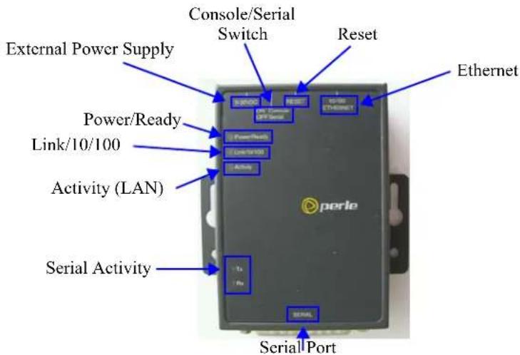
This section describes the components found on the IOLAN 1-port models.
text_image
External Power Supply Power/Ready Link/10/100 Activity (LAN) Serial Activity Console/Serial Switch Reset Ethernet Perle Serial PortThe 1-port IOLAN has one serial connection that is one of the following connectors: DB25 male, DB25 female, RJ45, or DB9 male.
2-Port
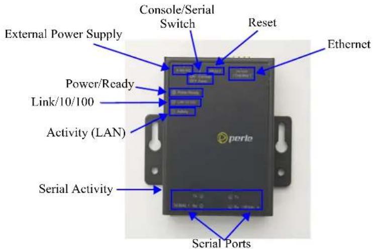
This section describes the components found on the IOLAN 2-port models.
text_image
External Power Supply Power/Ready Link/10/100 Activity (LAN) Serial Activity Console/Serial Switch Reset Ethernet Perle Serial PortsThe 2-port IOLAN has two RJ45 serial connections. The 2-port IOLAN can support an 8-pin connector if there is no requirement for power in (pin 1) or power out (pin 10) pins. The 2-Port P model (Power over Ethernet) does not come with an external power supply connector.
4-Port and 8-Port desktop models
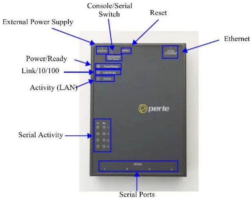
This section describes the components found on the IOLAN 4-port models.
text_image
External Power Supply Power/Ready Link/10/100 Activity (LAN) Serial Activity Console/Serial Switch Reset Ethernet Perle Serial PortsThe 4-port IOLAN model has four RJ45 serial connections. The STS8-D IOLAN model has eight RJ45 serial connections.
I/O
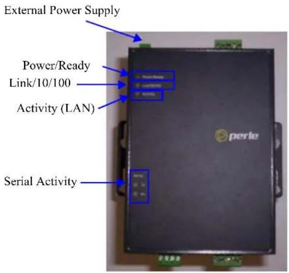
This sections describes the basic components found on the IOLAN I/O models.
Top View
The following image shows a typical IOLAN I/O model. Your I/O model may have I/O connectors in slightly different positions.
text_image
External Power Supply Power/Ready Link/10/100 Activity (LAN) Serial ActivityEnd View of IOLAN I/O
The IOLAN I/O model shown is an A4D2. Different IOLAN I/O models have different I/O connector configurations.
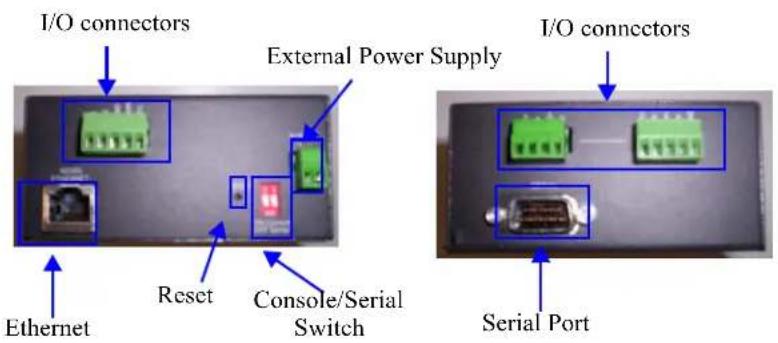
text_image
I/O connectors External Power Supply Ethernet Reset Console/Serial Switch I/O connectors Serial Port1-port, 2-port and 4-Port Wireless desktop models
This sections describes the components found on the IOLAN wireless models.
Top View (1 or 2 Port)
The following image shows an IOLAN one or two port wireless model.
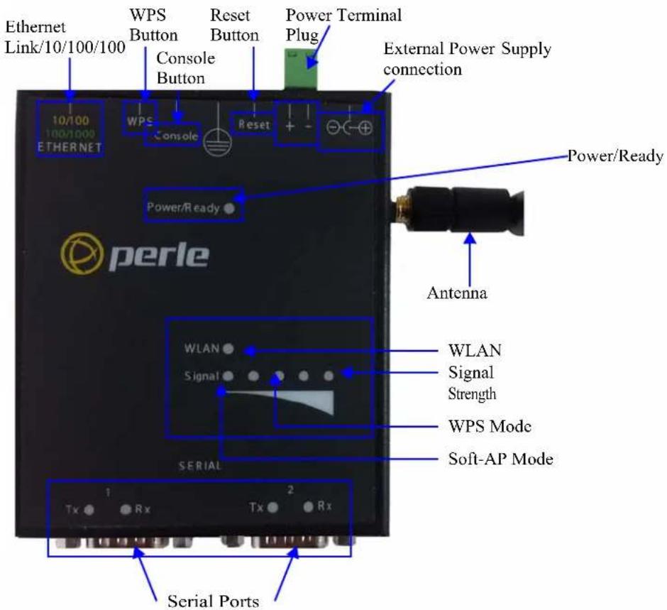
text_image
Ethernet Link/10/100/100 WPS Button Console Button Reset Button Power Terminal Plug External Power Supply connection 10/100 100/1000 ETHERNET WPS Console Reset + - Power/Ready Power/Ready perle Antenna WLAN Signal Strength WPS Mode Soft-AP Mode SERIAL Serial Ports Tx Rx Tx Rx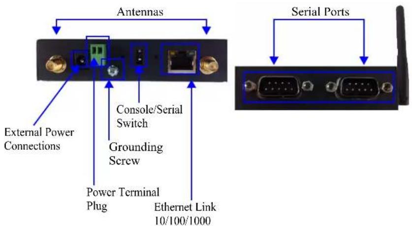
text_image
Antennas External Power Connections Console/Serial Switch Grounding Screw Power Terminal Plug Ethernet Link 10/100/1000 Serial PortsTop View (4 port RJ-45)
The following image shows an IOLAN Wireless model.
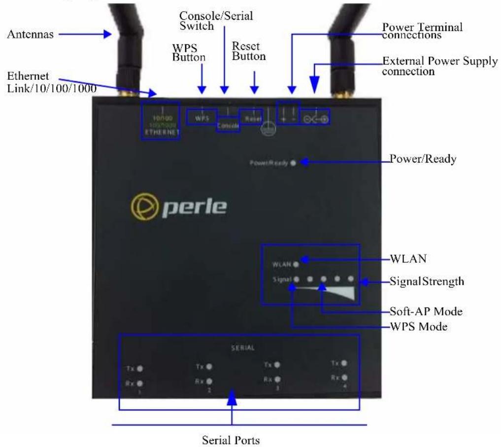
text_image
Antennas Ethernet Link/10/100/1000 Console/Serial Switch WPS Button Reset Button Power Terminal connections External Power Supply connection 100/00 100/00/00 WPS Console Reset + - Power/Ready Power/Ready perle WLAN SignalStrength WLAN Signal Soft-AP Mode WPS Mode SERIAL Tx Rx Tx Rx Tx Rx 3 2 3 4 Serial PortsEnd Views of IOLAN Wireless
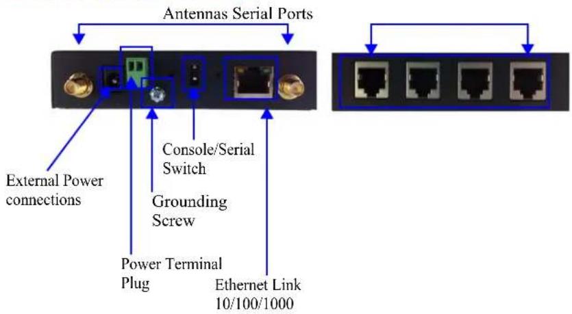
text_image
Antennas Serial Ports External Power connections Console/Serial Switch Grounding Screw Power Terminal Plug Ethernet Link 10/100/1000The 4-port IOLAN wireless has four RJ-45 serial connections. The 1-port and 2-port wireless IOLAN have either one or two DB9M connectors depending on the model.
Rack Mount
This section describes the basic components of all rack mount IOLAN models. This example uses the IOLAN SCS with dual Ethernet and dual AC power.
Console Port/LED View
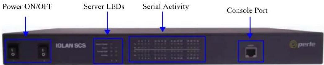
text_image
Power ON/OFF Server LEDs Serial Activity Console Port IOLAN SCS perleSerial/Ethernet View
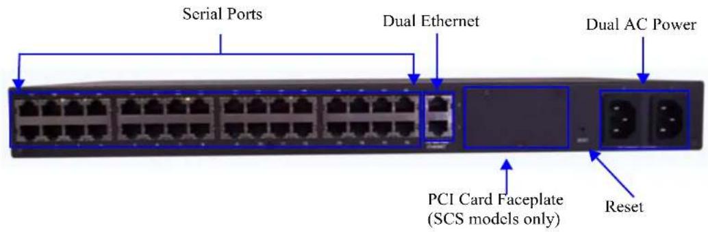
text_image
Serial Ports Dual Ethernet Dual AC Power PCI Card Faceplate (SCS models only) ResetMedical Unit
This section describes the basic components found on the IOLAN medical unit models.
Top View
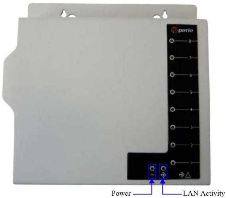
text_image
perle 8 7 6 5 4 3 2 1 Power LAN ActivitySerial View
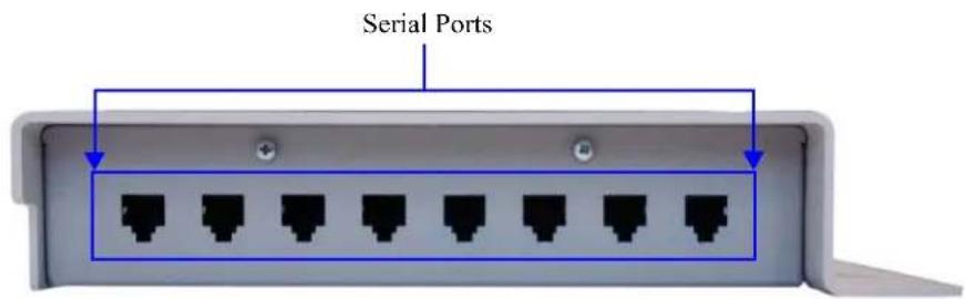
text_image
Serial PortsPower/Ethernet View
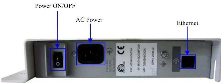
text_image
Power ON/OFF AC Power EthernetElectric Utility models
This section describes the basic components of the Electric Utility models. This example uses the SDS32C DHV model.
Front (LED/Console port)View
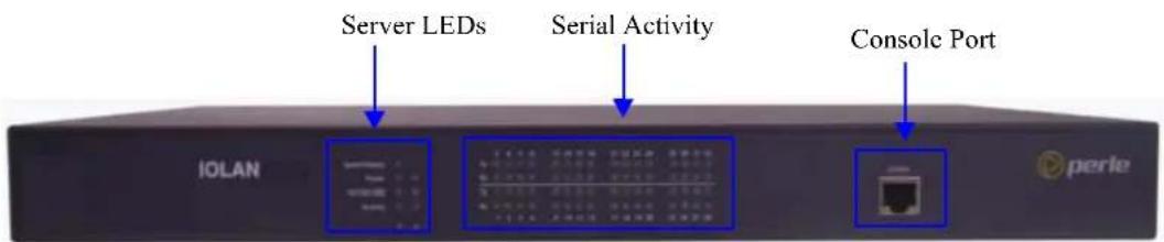
text_image
Server LEDs Serial Activity Console Port IOLAN perleBack (Serial/Ethernet/power) View

text_image
Serial ports Ethernet ports Reset switch Power/relay 125-2000C 380-3400C ~ 8000AConsole/Serial Switch
Located at the back of the desktop IOLAN models is a switch that controls whether serial port 1 is in Console or Serial mode.
The SDS T (Extended Temperature) models have two switches, Switch 1 is used for Console/Serial mode and Switch 2 is unused.
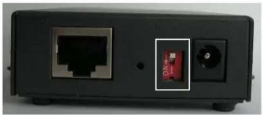
natural_image
Back view of a black electronic device showing port, socket, and internal component (no visible text or symbols)Look at your model to verify the direction of the ON switch position. ON indicates that serial port 1 is in Console mode; otherwise serial port 1 is in Serial mode.
Console Mode
Console mode is used when you have a direct connection between a serial device (like a terminal or a PC) and the IOLAN, accessed by the admin user to configure/manage the IOLAN. Console mode automatically sets serial port settings as:
- Serial Interface to EIA-232
- Speed to 9600
• Flow Control to No - Bits to 8
- Stop Bits to 1
Parity to None
Console mode also displays extra system messages.
Serial port 1 will ignore any Serial Port settings when in Console mode, so you need to turn Console mode off to use serial port 1 in your network.
When the console switch is in the on position, the Power/Ready LED will blink green.
Serial Mode
Serial mode is used when the IOLAN acts as a communications server, or anytime you are not connecting directly to the IOLAN to configure it. You can connect directly to the IOLAN in Serial mode, but the IOLAN will not display all the messages/information you will get in Console mode.
Dedicated Console Port
The rack mount IOLAN models have a dedicated Console port, located on the LED side of the IOLAN. You can use the supplied Administration cable (with the supplied RJ45→DB9F adapter if needed) to connect a terminal to the Console/Admin port to view diagnostic information and/or configure the IOLAN using the Menu or Command Line Interface (CLI). You can configure the baud rate and flow control of the dedicated Console port.
Connecting your IOLAN to the Network
To connect the IOLAN to the network, use a straight-through two-pair Category 5 unshielded twisted-pair (UTP) cable, or four-pair for Gigabit connections. Connect the RJ-45 Ethernet port on the IOLAN to a switch, hub, repeater, server or other network device.
To comply with the Telcordia GR-1089 NEBS standard, connect Ethernet interfaces only to intra-building or unexposed wiring or cabling. The intra-building cable must be shielded and the shield must be grounded at both ends.
Alternatively, if shielded cabling is not used, the Ethernet wiring (cabling) must directly connect to equipment within the same frame, cabinet or line-up and the equipment must be separated by a distance of 6 meters or less.
WARNING
The intra-building port(s) of the equipment or subassembly is suitable for connection to intra-building or unexposed wiring or cabling only. The intra-building port(s) of the equipment or subassembly MUST NOT be metallically connected to interfaces that connect to the OSP or its wiring. These interfaces are designed for use as intra-building interfaces only (Type 2 or Type 4 ports as described in GR-1089-CORE, Issue 4) and require isolation from the exposed OSP cabling. The addition of Primary Protectors is not sufficient protection in order to connect these interfaces metallically to OSP wiring.
Connecting the IOLAN to the Wi-Fi Network
The following steps allow for each connection to the IOLAN for initial configuration.
Initial Setup - Soft-AP Method
-
The IOLAN must be powered up.
-
Press the inset WPS button (using a paper clip) for 4 seconds to enable Soft-AP mode. The Signal strength LED display should show a pulsing green LED on the third light from the left to right to confirm you are in Soft-AP mode (See IOLAN Top Views).
-
The IOLAN is listed on your network connections on your PC or wireless client. It will appear as SSID: IOLAN-xxxxxx (the last 6 digits of the IOLAN wireless MAC address - found on the product label).
-
If using the password entry method: Select the wireless network on the PC, when a password is requested enter the password printed on the product label
-
If using the WPS method: press and release the WPS button on the IOLAN select the wireless network on the PC select the WPS option on the PC's password dialog box
-
Should a dialog box appear on your PC's screen to connect to the network, press the continue/Ok button to complete the connection to the IOLAN.
- Use a Web browser to connect to the default address of the IOLAN at (192.168.0.1).
The default userid is admin and the default password is superuser (case sensitive).
You can now configure and manage your IOLAN using the IOLAN WebManager application.
Note: You should change the admin password to restrict unauthorized access to your IOLAN.
For additional methods of configuring your IOLAN (i.e., HTTP, Telnet, SNMP), please refer to the IOLAN User's Guide.
Powering up your IOLAN
Desktop/Rack Mount Models (excluding Electric Utility models)
To power up the desktop or rack mount IOLAN, perform the following steps:
- Rack mount models only: Using the rack mount brackets included with your IOLAN, you can rack mount the IOLAN from the front or the back of the chassis, depending on your environment. Make sure you don't block the IOLAN's side air vents. Each IOLAN is 1U in height, and does not require any extra space between units; therefore, you can rack mount up to five IOLANs in a 5U rack.
- Plug the external power supply into the IOLAN and then into the electrical outlet. Connect it to the PSE if you have a P series (Power over Ethernet) model.
- Rack mount models only: Power on the IOLAN unit using the Power ON/OFF switch.
- You will see the LEDs blink for several seconds and then remain a solid green, indicating that it is ready to configure/use.
Before you start to configure the IOLAN, you should set the desktop IOLAN jumpers if you want to terminate the line or use the power in pin feature (instead of an external power supply, if your desktop IOLAN model supports it).
In some circumstances, the setting of jumpers may be required:
- IOLAN DS and SDS models where EIA-422/485 line termination is required.
- IOLAN I/O models with Digital I/O for setting the channels as input or output.
- IOLAN I/O models with Analog I/O for setting Voltage/Current.
See Appendix F, Setting Jumpers to see how to set the jumpers for your IOLAN desktop model.
Medical Unit Models
To power up the medical unit IOLAN, perform the following steps:
- You can attach the multi-function wall plate included with your medical unit IOLAN to the wall, then mount the IOLAN on the wall plate. Alternatively, you can mount the IOLAN on a tabletop or any suitable horizontal surface. See the IOLAN MDC Hardware Installation Guide for more information on how to mount the medical unit IOLAN.
- Plug a power cable into the left side (power/Ethernet panel) of the IOLAN unit and then into the electrical outlet.
- Power on the IOLAN unit using the Power ON/OFF switch.
- You will see the LEDs blink for several seconds and then remain a solid green, indicating that it is ready to configure/use.
Terminal Block Models
Perform the following steps to power up the unit:
-
Ensure power is NOT applied to the wires prior to connection.
-
On each end wire, remove the insulation from the copper wire 5 mm (3/16 of an inch).
For I/O models the Terminal Block is pluggable.
- Loosen the left screw on the top of the terminal connector block, then insert your positive (+) wire into the left terminal and screw it down tight. Loosen the right screw on the top of the terminal connector block, then insert your negative (-) wire into the right terminal and screw it down tight.
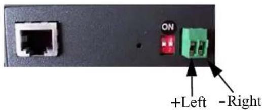
text_image
+Left -Right-
Plug the power supply into the electrical outlet.
-
A solid green LED indicates the unit is powered up.
For I/O models, you should set the IOLAN jumpers for Digital I/O (see Digital I/O Module) or Analog Input (Analog Input Module) channels.
DC Power Models (excluding Electric Utility models)
To power up the IOLAN with DC power requirements, perform the following steps:
-
Verify that the power switch on the IOLAN unit and the power source is in the Off position.
-
Connect the primary and secondary DC input using the following specifications:
a. Use wire gauge 12 to 22 AWG.
b. Strip insulation 7mm from wire ends. (If using stranded wire, twist all strands together to ensure all wire strands are used for the connection.)
c. Connect supply with reference to the terminal block diagram and electrical specifications:
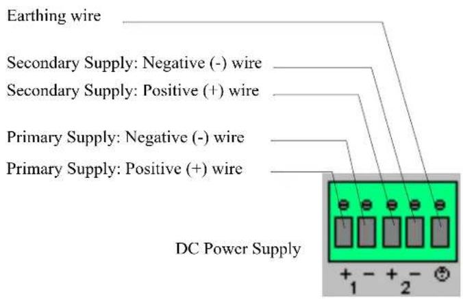
text_image
Earthing wire Secondary Supply: Negative (-) wire Secondary Supply: Positive (+) wire Primary Supply: Negative (-) wire Primary Supply: Positive (+) wire DC Power Supply + - + - + 1 2When connecting only a single power supply source, ensure the connection is the primary supply and the secondary terminals are left unconnected.
Primary Supply:
Positive (+) wire to Circuit 1, terminal marked +
Negative (-) wire to Circuit 1, terminal marked -
Secondary (back-up) Supply:
Positive (+) wire to Circuit 2, terminal marked +
Negative (-) wire to Circuit 2, terminal marked -
Note: When connecting dual power supply sources, the IOLAN supports a common positive (+) circuit arrangement ONLY.
Earthing Wire:
Ground wire to terminal marked with circular earthing symbol.
Screws:
Tighten terminal connector block screws to 4.5 lbs-inches (0.51Nm) torque.
-
Switch On the power supplies.
-
Switch On the IOLAN. (The power LEDS 1 and 2 will indicate the status of the power source at the respective input. If both the primary and secondary power source are available, both LED 1 and LED 2 will be luminated indicated power detected from each input.)
Disconnecting 48V Power Supplies from the IOLAN
To disconnect the power supply(s) from the IOLAN, do the following:
- Switch off the IOLAN.
- Switch off the power source(s).
- Disconnect all DC power input cables from the IOLAN terminal connector block.
- Remove any attached devices to the serial or Ethernet port(s).
Your IOLAN is ready to be moved.
Electric Utility Models
To power up the IOLAN, Electric Utility models, perform the following steps:
- Ensure that the power supply side of the connection is been powered down before attempting to connect the wires on the IOLAN side.
- Connect the power as outlined in the "wiring" section below which matches your model.
- Enable power to unit. Unit should now power up. Selecting Install Locations for LDC Models
Wiring
Safety warnings for ALL Electric Utility models
The Electric Utility series of IOLAN units do not have a power switch, and an appropriately rated circuit breaker must be installed externally to the unit. If two power sources are used, each source must have a circuit breaker. As a safety precaution you should not rely upon the unit's front panel LEDs as a power indicator.
Safety warnings for HV and DHV models.
Note:
WARNING
This unit should be installed in a restricted access location where access can only be gained by service personnel or users who have been instructed about the reasons for the restrictions applied to the location and about any precautions that shall be taken; and access is through the use of a tool or lock and key, or other means of security, and is controlled by the authority responsible for the location.
All equipment must be installed according to the applicable country wiring codes.
Grounding of HV and DHV models
The Electric Utility series of IOLAN units have a chassis ground screw. This connection must be connected to "Equipment Ground" for DC installations or "Safety Ground" for AC installations. A second "earth ground" connection is provided for secondary grounding. This should only be used in conjunction with the grounding screw provided on the terminal connector.
Note:
For your safety, before attempting to connect or modify any of the electrical connections to the unit, please be sure all wiring is disconnected from any live power source. Power should only be applied when you are sure that the wiring is correct and any safety covers are properly installed.
Wiring up an HV unit
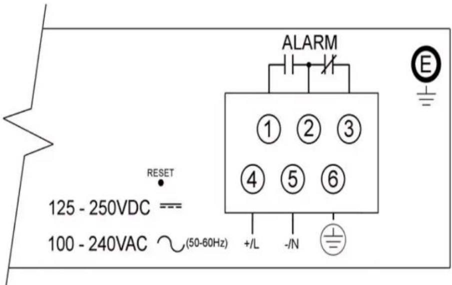
text_image
ALARM ① ② ③ ④ ⑤ ⑥ E RESET 125 - 250VDC === 100 - 240VAC ∼(50-60Hz) +/- L - / N +/-| Terminal # | Description Usage | |
| 1 | Normally Open | Normally Open is a fail-safe relay connection. Use this with the Common terminal to act as switch contacts that remain open when the unit is powered off or in a failure state. |
| 2 | Common | Common is a fail-safe relay connection. Use this terminal in conjunction with the Normally Open or Normally Closed terminals. |
| 3 Normally Closed | Normally Closed is a fail-safe relay connection. Use this with the Common terminal to act as switch contacts that remain closed when the unit is powered off or in a failure state. | |
| 4 | +/L | +/L is connected to the positive (+) input for DC sources or to the Live input for AC sources. Use with partner terminal -/N. |
| 5 | -/N | -/N is connected to the negative (-) input for DC sources or to the Neutral input for AC sources. Use with partner terminal +/L. |
| 6 | Chassis Ground | Chassis Ground must be connected to "Equipment Ground" for DC installations or "Safety Ground" for AC installations. |
| E | Earth Ground | Earth Ground is a connection to the chassis that can be used for earth bonding. |
NOTES:
- For terminal# 1 through 6, the use of ring terminals size #6 (M3.5) is recommended using stranded wire size AWG 18-14. Tighten all screws to a torque of 12 Lb-in (1.36 Nm).
- For terminal# E, the use of ring terminal size #8 (M4) is recommended using stranded wire size AWG 18-14. Tighten screw to a torque of 12 Lb-in (1.36 Nm).
- Use the "Chassis Ground" terminal connection for grounding the unit. "Earth Ground" should be used as secondary grounding source only.
- Be sure to replace the clear plastic electrical safety shield before applying power to the unit.
| Terminal # | Description Usage | |
| 1 | Normally Open | Normally Open is a fail-safe relay connection. Use this with the Common terminal to act as switch contacts that remain open when the unit is powered off or in a failure state. |
| 2 | Common | Common is a fail-safe relay connection. Use this terminal in conjunction with the Normally Open or Normally Closed terminals. |
| 3 Normally Closed | Normally Closed is a fail-safe relay connection. Use this with the Common terminal to act as switch contacts that remain closed when the unit is powered off or in a failure state. | |
| 4 | Chassis Ground | Chassis Ground must be connected to "Equipment Ground" for DC installations or "Safety Ground" for AC installations. |
| 5 | +/L (source 1) | +/L (Source 1) is connected to the positive (+) input for DC sources or to the Live input for AC sources. Use with partner terminal -/N(Source 1). |
| 6 | -/N(source 1) | -/N (Source 1) is connected to the negative (-) input for DC sources or to the Neutral input for AC sources. Use with partner terminal +/L(Source 1). |
| 7 | +/L (source 2) | +/L (Source 2) is connected to the positive (+) input for DC sources or to the Live input for AC sources. Use with partner terminal -/N(Source 2). |
| 8 | -/N(source 2) | -/N (Source 2) is connected to the negative (-) input for DC sources or to the Neutral input for AC sources. Use with partner terminal +/L(Source 2). |
| E | Earth Ground | Earth Ground is a connection to the chassis that can be used for earth bonding. |
NOTES:
- For terminal# 1 through 8, the use of ring terminals size #6 (M3.5) is recommended using stranded wire size AWG 18-14. Tighten all screws to a torque of 12 Lb-in (1.36 Nm).
- For terminal# E, the use of ring terminal size #8 (M4) is recommended using stranded wire size AWG 18-14. Tighten screw to a torque of 12 Lb-in (1.36 Nm).
- Use the "Chassis Ground" terminal connection for grounding the unit. "Earth Ground" should be used as secondary grounding source only.
- Be sure to replace the clear plastic electrical safety shield before applying power to the unit.
Wiring up a LDC unit
- Ensure that the power supply side of the connection is been powered down before attempting to connect the wires on the IOLAN side.
- Connect the power as outlined in the "wiring" section below.
- Enable power to unit. Unit should now power up.
CAUTION
ESD sensitivity: This product contains Electrostatic Sensitive Devices. Follow ESD mitigative procedures during installation and maintenance.
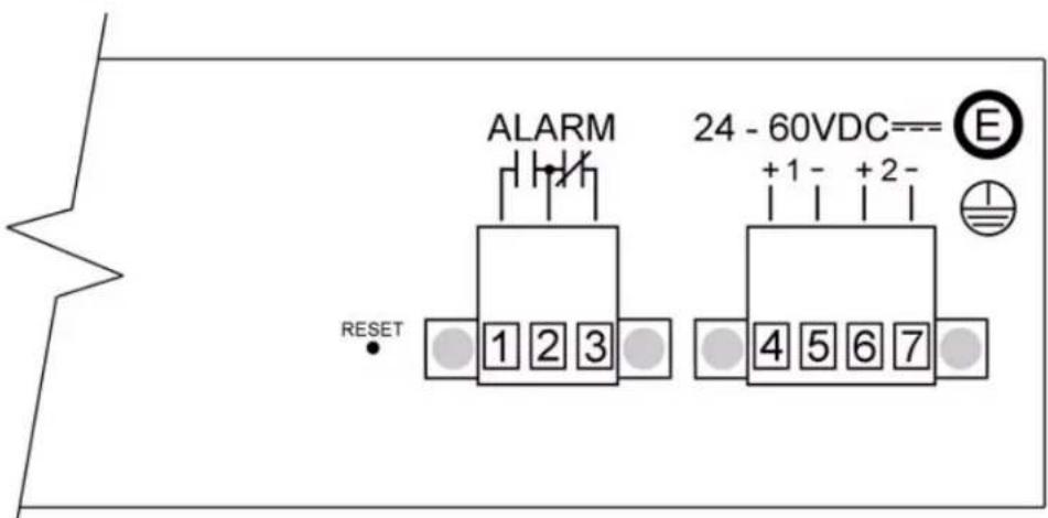
text_image
ALARM 24 - 60VDC--- E 1 2 3 +1 - +2 - 4 5 6 7 RESET| Terminal # | Description Usage | |
| 1 | Normally Open | Normally Open is a fail-safe relay connection. Use this with the Common terminal to act as switch contacts that remain open when the unit is powered off or in a failure state. |
| 2 | Common | Common is a fail-safe relay connection. Use this terminal in conjunction with the Normally Open or Normally Closed terminals. |
| 3 Normally Closed | Normally Closed is a fail-safe relay connection. Use this with the Common terminal to act as switch contacts that remain closed when the unit is powered off or in a failure state. | |
| 4 | Input 1+ | Input 1+ is connected to the positive (+) input or the DC sources. Use with partner terminal Input 1-. |
| 5 | Input 1- | Input 1- is connected to the negative (-) input or the DC sources. Use with partner terminal Input 1+. |
| 6 | Input 2+ | Input 2+ is connected to the positive (+) input or the DC sources. Use with partner terminal Input 2-. |
| 7 | Input 2- | Input 2- is connected to the negative (-) input or the DC sources. Use with partner terminal Input 2+. |
| E | Chassis Ground | Chassis Ground is a connection to the chassis that can be used for earth bonding. |
NOTES:
- For terminal# 1 through 7, strip insulation from wire 9/32-5/16 (7 -8mm) using stranded wire size 18-12 AWG. Tighten screw to a torque of 4.5 Lb-in (0.51Nm).
- For terminal# E (Chassis ground), the use of ring terminal size #8 (M4) is recommended using stranded wire size AWG 18-14. Tighten screw to a torque of 12 Lb-in (1.36 Nm).
- When power is applied, if both sources are available, both power LED 1 and LED 2 (on front of unit) will be luminated indicating power detected from both sources.
- Unit is suitable for installation as part of the Common Bond Network (CBN). The LDC's power supply input terminals are isolated from the equipment frame ground.
TELCO - NEBS Models
The Perle IOLAN LDC TELCO-NEBS models have been certified to be NEBS compliant.
To ensure compliance, power up the IOLAN LDC model and perform the following steps:
- Ensure that the power supply side of the connection is been powered down before attempting to connect the wires on the IOLAN side.
- Connect the power as outlined in the "wiring" section below.
- Enable power to unit. Unit should now power up.
Safety warnings for TELCO - NEBS models.
The TELCO - NEBS series of IOLAN units do not have a power switch, and an appropriately rated circuit breaker must be installed externally to the unit. If two power sources are used, each source must have a circuit breaker. As a safety precaution you should not rely upon the unit's front panel LEDs as a power indicator.
Install Locations for LDC Models
The unit may be installed in one of the following locations.
• Network Telecommunications Facilities. (such as a central office).
- Locations where the NEC (National Electric Company) guidelines apply such as customer premises, general business offices, residential and retail.
- OSP (Outside Plant) such as outside cabinets and environmental locations.
Wiring up a the Fail-Safe Relay
The LDC series of IOLAN units are also fashioned with a Fail-Safe Relay. The relay is engaged after the unit is powered up and the software has loaded properly. Should a failure occur, the relay will be disengaged until the unit returns to a normal state of operation. A failure is defined as a condition which causes the unit to stop running.
A SPDT set of contacts are provided to the user. These three contact connections are known as "Common", "Normally Open" and "Normally Closed", and are electrically isolated to the relay. The contacts are rated for voltages up to 30VDC /AC with a maximum current of 3A.

natural_image
Yellow circular logo with the number '2' in black, surrounded by abstract star-like patterns (no text or symbols)Introduction
About the IOLAN
The IOLAN is an Ethernet communications/terminal server that allows serial devices to be connected directly to LANs. The IOLAN can connect to a wide range of devices including:
• Terminals for multi-user UNIX systems
• Data acquisition equipment (manufacturing, laboratory, scanners, etc.)
● Retail point-of-sale equipment (bar coding, registers, etc.)
• PCs using terminal emulation or SLIP/PPP
• Modems for remote access and Internet access
• ISDN adapters for branch remote access and Internet access
• All types of serial printers
The performance and flexibility of the IOLAN allows you to use a wide range of high speed devices in complex application environments. The IOLAN products will work in any server environment running TCP/UDP/IP.
IOLAN Family Models
The IOLAN comes in several different models to meet your network needs:
- DS—Offered as a 1-port unit (DB25M, DB25F, RJ45, and DB9M interfaces available), this model provides general IOLAN functionality and supports software configurable serial interface protocols EIA-232/422/485.
- TS—This model is available with two serial ports (RJ45 only) and supports EIA-232 only. The TS model is similar to the DS model supporting only general IOLAN functionality.
- SDS—This model is available in both desktop and rack mount configurations. Both models support software configurable serial interface protocols EIA-232/422/485. The SDS model has the advanced secure IOLAN feature set in addition to the general IOLAN functionality. The SDS models also include the “Electric Utility” variants which include both HV (High Voltage AC and DC) and LDC (Low Voltage DC) models as well as the TELCO-NEBS LDC model. The Iolan SDS M model supports 1 or 3 serial ports with an integrated V.92 modem. The SDS P is 802.3af Power over Ethernet complaint. Ethernet interface speeds of 10/100 Mbps.
STS—This model comes in two desktop models and several rack mount configurations. All models support EIA-232 only except for the STS P which utilizes Power over Ethernet technology. The STS model has the advanced secure IOLAN feature set in addition to the general IOLAN functionality. - SCS—This model comes in several rack mount configurations. All models support EIA-232 only and have an internal PCI card interface. The internal PCI card interface can be used either for installation of a V.92 modem card or optionally a wireless fiber card. The SCS model has the advanced secure IOLAN feature set in addition to the general IOLAN functionality.
- MDC—Offered as a 4-port and 8-port unit (RJ45 only), this model is a medical unit compliant with IEC 60601-1 and has galvanically isolated EIA-232 serial ports. The MDC model has the advanced secure IOLAN feature set in addition to the general IOLAN functionality.
- HL— Offered as a 4-port unit (RJ45 only), this model is a Hazard Location model. The SDS HL model is suitable for use in Class I, Division 2 groups A, B, C, D or unclassified locations.
NOTE: In order to comply with the ATEX directive, the IOLAN SDS4 HL must be installed in an ATEX certified IP54 min. enclosure and the IOLAN SDS4 HL must be installed so that the unit's labelling is visible.
- W—Offered as a 1-port and 2-port unit with DB9M connectors and as a 4-port RJ45 model with RJ-45 connectors. All models provide Serial to Wi-Fi, Serial to Ethernet and Ethernet to Wi-Fi connectivity. Industry standard wireless networking using 802.11 a/b/g/n and robust configurable wireless security methods WEP, WPA-PSK & Enterprise (EAP, PEAP, LEAP), 802.11i.
- See Hardware for information about the hardware specifications for your IOLAN model.
• See Software for a list of the basic and advanced software features.
IOLAN Features
The IOLAN is a communications server used for making serial network connections. It attaches to your TCP/IP network and allows serial devices such as modems, terminals, or printers to access the WLAN/LAN. It also allows WLAN/LAN devices to access devices or equipment attached to IOLAN serial ports.
This section highlights the hardware and software components you can expect to find in your IOLAN model.
Hardware
| Hardware Features IOLAN Models | ||||||||||||||
| Desktop Rack Mount Medical | ||||||||||||||
| DS1 | DS1 I/O | TS2 | SDS1/3 | SDS1/2/4 P | SDS1 I/O | SDS2/4I/L | STS4 P | STS48D | SDS 1/2/4 W | SDS | SCS | STS | ||
| Serial Connectors | DB25F | ● | ● | |||||||||||
| DB25M | ● | ● | ||||||||||||
| RJ45 | ● | ● ● | ● | ● ● | ● | ●3 | ● | ● | ● | |||||
| DB9M | ● | ● | ● | ● | ● | |||||||||
| Galvanically Isolated Serial Ports | RJ45 | |||||||||||||
| Serial Interface | EIA-232 | ● | ● | ● | ● | ● | ● | ● | ● | ● | ● | ● | ● | ● |
| EIA-422 | ● | ● | ● | ● | ● | ● | ● | ● | ||||||
| EIA-485 | ● | ● | ● | ● | ● | ● | ● | ● | ||||||
| Hardware Features | IOLAN Models | ||||||||||||||
| Desktop Rack Mount Medical | unit | ||||||||||||||
| DS1 | DS1 I/O | TS2 | SDS1/3 | SDS1/2/4 P | SDS1 I/O | SDS2/4HL | STS4 P | STS4/8D | SDS 1/2/4 W | SDS | SCS | STS | MDC | ||
| Serial Power In Pin | DB25F | ● | ● | ||||||||||||
| DB25M | ● | ● | |||||||||||||
| RJ45 | ● | ● | ● | ● | ● | ●1 | |||||||||
| Serial Power Out Pin | DB25F | ● | |||||||||||||
| DB25M | ● | ||||||||||||||
| RJ45 | ● | ● | ● | ● | ●1 | ||||||||||
| Auto Sensing Ethernet Interface | 10/100 | ● | ● | ● | ● | ● | ● | ● | ● | ● | ● | ||||
| 10/100/1000 | ● | ● | ● | ● | |||||||||||
| Wireless Technology | ● | ||||||||||||||
| PCI Interface | ● | ||||||||||||||
| I/O Interface | ● | ● | |||||||||||||
| Optional V.92 Modem | ● | ● | |||||||||||||
| Power Supply | Power over Ethernet | ● | ● | ||||||||||||
| External AC | ● | ● | ● | ●2 | ● | ●2 | ● | ● | |||||||
| Internal AC | ● | ● | ● | ● | |||||||||||
| DC | ● | ● | ● | ● | ● | ||||||||||
| Dedicated Console Port | ● | ● | ● | ||||||||||||
Note 1: Not supported on STS8-D.
Note 2: Optional power supply.
Note 3: RJ45 connectors only available on 4-port model.
Software
This section describes the supported software features available.
Accessing the IOLAN
All IOLAN models can be accessed through any of the following methods:
- Easy Config Wizard, an easy configuration wizard that allows you to quickly setup the IOLAN in a Windows ^ environment
- DeviceManager, a fully functional Microsoft, Windows NT ^ /Windows 2000 ^ /Windows Vista ^ /Windows Server 2003 ^ /Windows 2003 R2 ^ /Windows 2008 ^ /Windows 2008 R2 ^ /Windows XP ^ /Windows 7 ^ /Windows 8 ^ /Windows 8.1 ^ /Windows Server 2012 ^ and Server 2012 R2 ^ configuration/management tool.
WebManager, a web browser (HTTP/HTTPS) option for configuring/managing the IOLAN - Menu, a window-oriented menu interface for configuration and user access
- CLI, a Command Line Interface option for configuration/management and user access
• SNMP, allowing remote configuration via SNMP as well as statistics gathering - DHCP/BOOTP, a method of automatically updating the IOLAN
- IOLAN+ interface, for IOLAN+ users, IOLAN models with 16 ports or fewer can be configured using the IOLAN+ menu
General Features
Basic IOLAN software features are available on all IOLAN models.
- IPv6 support.
- Support for TCP/IP and UDP protocols including telnet and raw connections.
• Printer support via LPD and RCP.
• Virtual modem emulation. - ‘Fixed tty’ support for several operating systems using Perle’s TruePort utility.
- DHCP/BOOTP for automated network-based setup.
• Dynamic statistics and line status information for fast problem diagnosis. - Multisession support when accessing the IOLAN from either the serial port or the network.
- Modbus master/slave/gateway support.
- An SDK for custom programs and plugin support.
- I/O interface on the IOLAN I/O models (Analog, Temperature, Digital, and Relay).
- Ability to disable services (for example, Telnet, TruePort, Syslog, SNMP, Modbus, HTTP) for additional security.
- Ability to enable Ping responses.
Advanced Features
Advanced IOLAN software features can be found on all IOLAN models except DS and TS models.
- External authentication using any of the following systems:
-RADIUS
- Kerberos
-TACACS+
-NIS
- SecurID
- LDAP/Microsoft Active Directory
• Support for TCP/IP and UDP protocols.
• Dynamic DNS with DYNDNS.org.
• Domain Name Server (DNS) support.
- WINS support for Windows ^ environments.
- Remote access support including PPP, SLIP, and SLIP with VJ Compression.
- Ability to remotely manage the Perle Remote Power Switch (RPS).
- Ability to cluster several IOLANs.
- Email alert notification.
- PPP authentication via PAP /CHAP/ MSCHAP.
- CHAP(MD5) authentication support to TACACS+ servers.
- SSH connections (supported ciphers are Blowfish, 3DES, AES-CBC, AES-CTR, AES-GMC, CAST, and ChaCha20-Poly1305).
- SSL/TLS connections.
- Logging via Syslog.
- RIP authentication (via password or MD5).
• SNTP (versions 1, 2, 3, and 4 are supported).
Security
The IOLAN security features can include (depending on your IOLAN model):
• Supervisory and serial port password protection.
- Ability to set serial port access rights.
- Ability to assign users access level rights to control their access.
- Trusted host filtering (IP filtering), allowing only those hosts that have been configured in the IOLAN access to the IOLAN.
- Idle port timers, which close a connection that has not been active for a specified period of time.
- Ability to individually disable network services that won't be used by the IOLAN.
- SSH client/server connections (SSH 1 and SSH 2).
- SSL/TLS client/server data encryption (TLSv1/1.1/1.2 and SSLv2).
- Ability to setup Virtual Private Networks.
- Access to firewalled/Nated devices via HTTP tunnels.
- Wireless Security; WEP, WPA2-PSK & Enterprise (EAP, PEAP, LEAP), 802.11i.

text_image
3Configuration Methods
Introduction
This chapter provides information about the different methods you can use to configure the IOLAN. Before you can configure the IOLAN, you must assign an IP address to the IOLAN. See the Chapter 4, Getting Started to find out how to assign an IP address to the IOLAN.
Once an IP address is assigned to the IOLAN, you can use any of the configuration methods to:
- Configure users.
- Configure IOLAN server parameters.
- Configure serial port parameters.
- Configure network parameters.
- Configure time parameters.
- Reboot the IOLAN.
- Manage the Perle Remote Power Switch (when applicable).
- Manage I/O channels (when applicable).
• View statistics while connected to the IOLAN.
Configuration Methods Overview
Some of the IOLAN configuration methods have the capability of configuring an IP address, which is the first required configuration step for a new IOLAN. Once the IOLAN has been assigned an IP address, any of the configuration methods can be used to configure the IOLAN.
Configures an IP Address
Following is a list of methods for setting the IOLAN IP address and a short explanation of when you would want to use that method:
- Easy Config Wizard—The Easy Config Wizard is available from the CD ROM included with your IOLAN. You can use the Easy Config Wizard to set the IOLAN's IP address and configure serial ports. This configuration method would typically be used when:
- All ports are to have the same configuration.
- Only the most commonly used profiles are required.
- Straightforward application with no advanced functionality required.
- Easy Config is installed on a Windows ^ -based PC with local network access to the IOLAN.
- DeviceManager—Use this method when you can connect the IOLAN to the network and access the IOLAN from a Windows® PC. The DeviceManager is a Windows®-based application that can be used for IOLAN configuration and management. The DeviceManager can be used to assign an IP address and perform the complete configuration and management of the IOLAN.
- Direct Connection—Use this method when you can connect to the IOLAN from a serial terminal or from a computer running terminal emulation software over a serial port. Using this method, you will need to configure and/or manage the IOLAN using either the Menu or CLI.
- DHCP/BOOTP—Use this method when you have a BOOTP or DHCP server running and you can connect the IOLAN to your network. The IOLAN will automatically obtain an IP address from a local network DHCP/BOOTP server when this service is enabled (it is disabled by default). You can also configure certain IOLAN parameters that will be passed from the DHCP/BOOTP server to the IOLAN when it boots up. Other configurators such as DeviceManager, CLI, or Menu can be used to set this option, and obtain the initial IP address.
- ARP-Ping—Use this method when you can connect the IOLAN to the network and want to assign a temporary IP address to the IOLAN by adding an ARP entry to your PC and then pinging it.
- IPv6 Network—When the IOLAN is connected to an IPv6 network, its local link address is determined using stateless auto configuration.
Once an IP address has been assigned to the IOLAN, in most cases, you can continue to use the same method if it is a configurator or you can switch to any other configuration method.
Requires a Configured IP Address
The following configuration methods require that an IP address already be assigned to the IOLAN.
- WebManager—WebManager is a fully functional, browser-based configuration method.
- IOLAN+ Interface—The IOLAN+ interface is available on IOLAN models that are 1-16 ports (this is not supported on DS1, TS2, and medical unit models) and uses the interface that is available on the IOLAN+ product line.
Easy Config Wizard
The Easy Config Wizard is a configuration wizard that will configure all the serial ports on your IOLAN to one of the following:
- Console Management
• TruePort (Virtual COM Port) - TCP Sockets (Raw TCP)
- Terminal
• Printer (not supported on DS1/TS2 models) - Serial Tunneling
You can launch the Easy Config Wizard from the Perle website or from the installation CD-ROM.
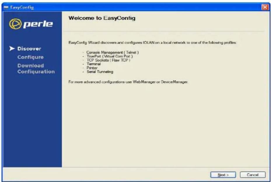
text_image
EasyConfig Welcome to EasyConfig EasyConfig Wizard discovers and configures IOLAN on a local network to one of the following profiles: - Console Management ( Telnet ) - TruePort ( Virtual Com Port ) - TCP Sockets ( Raw TCP ) - Terminal - Printer - Serial Tunneling For more advanced configurations use WebManager or DeviceManager. Next > CancelThe Easy Config Wizard has been designed to walk you through the configuration process for any of the available configuration options shown on the Welcome window.
DeviceManager
Overview
The DeviceManager is a Windows ^® -based application that can be used to connect to the IOLAN to actively manage and configure it or can create new IOLAN configurations offline. See Chapter 5, Using DeviceManager and WebManager for information on configuring/managing the IOLAN with DeviceManager.
Access Platforms
The DeviceManager can be run from Microsoft, Windows NT ^® /Windows 2000 ^® /Windows Vista ^® /Windows Server 2003 ^® /Windows 2003 R2 ^® /Windows 2008 ^® /Windows 2008 R2 ^® /Windows XP ^® /Windows 7 ^® /Windows 8 ^® /and Windows Server 2012 ^® .
DeviceManager can be installed from the product CD-ROM or downloaded from the Perle website. Unless the IOLAN has already been configured with a Gateway, DeviceManager can only access IOLANs in the local subnet. The DeviceManager can be accessed by only the admin user.
Features
DeviceManager supports the following features:
- The ability to download the same configuration file to several IOLANs in one operation.
- The ability to save a configuration file locally in text format, in addition to the binary format.
- The ability to create a configuration file without being connected to the IOLAN.
- The ability to open a session to the IOLAN and download a (saved) configuration file to it.
- The ability to download/upload keys/certificates to/from the IOLAN.
- The ability to download custom files, such as new terminal definitions and a custom language files to the IOLAN.
Connecting to the IOLAN Using DeviceManager
Before you can use DeviceManager, you need to install it on your Windows operating system from the IOLAN CD-ROM or you can download it from the Perle website. After the DeviceManager application is installed, click Start, All Programs, Perle, DeviceManager, DeviceManager to start the application. When you launch the DeviceManager, it will scan the network for IOLANs:
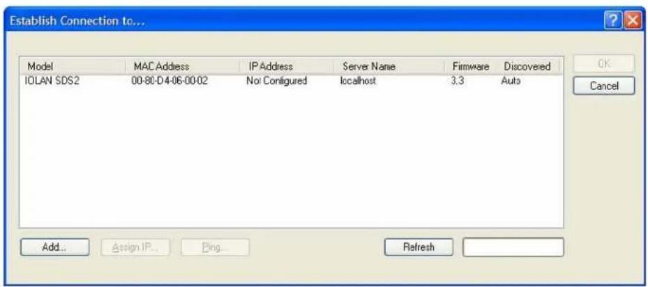
text_image
Establish Connection to... Model MAC Address IP Address Server Name Firmware Discovered IOLAN SDS2 00-80-D4-06-00-02 No! Configured localhost 3.3 Auto Add... Assign IP... Bing... Refresh OK CancelAll discovered IOLANs will be displayed on the list along with their name and IP address. When a new IOLAN is discovered on the network, that has not yet been assigned an IP address, it will be displayed with an IP Address of Not Configured. To configure the IP address, click on the IOLAN and then click the Assign IP button.
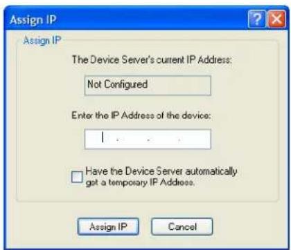
text_image
Assign IP Assign IP The Device Server's current IP Address: Not Configured Enter the IP Address of the device: I ..... Have the Device Server automatically got a temporary IP Address. Assign IP CancelChoose the method you want to use to assign an IP address to the IOLAN:
- Type in the IP address that you want to assign to this IOLAN.
- Enable the Have the IOLAN automatically get a temporary IP Address option. This will turn on DHCP/BOOTP, so the IOLAN will attempt to get its IP address from your DHCP/BOOTP server. If you don't have a DHCP/BOOTP server, DeviceManager will temporarily assign an IP address in the range of 169.254.0.1-169.254.255.255 that will be used only for the duration of the DeviceManager/IOLAN communication.
After you configure the IP address, click the Assign IP button.
The refreshed list will now display the assigned IP address for the new IOLAN. To connect to the IOLAN, click the IOLAN entry and click OK. You will be asked to supply the admin password (the factory default password is superuser).
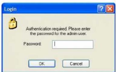
text_image
Login Authentication required. Please enter the password for the admin user. Password: 1 OK CancelIf you have a successful connection, the DeviceManager will retrieve the configuration and then display the IOLAN's System Information and you can begin configuring the IOLAN.
The DeviceManager does not automatically update the IOLAN's configuration. You must download the configuration changes to the IOLAN and then reboot the IOLAN to make the configuration changes take effect.
Using DeviceManager
After you have successfully connected to the IOLAN, DeviceManager displays the following window:
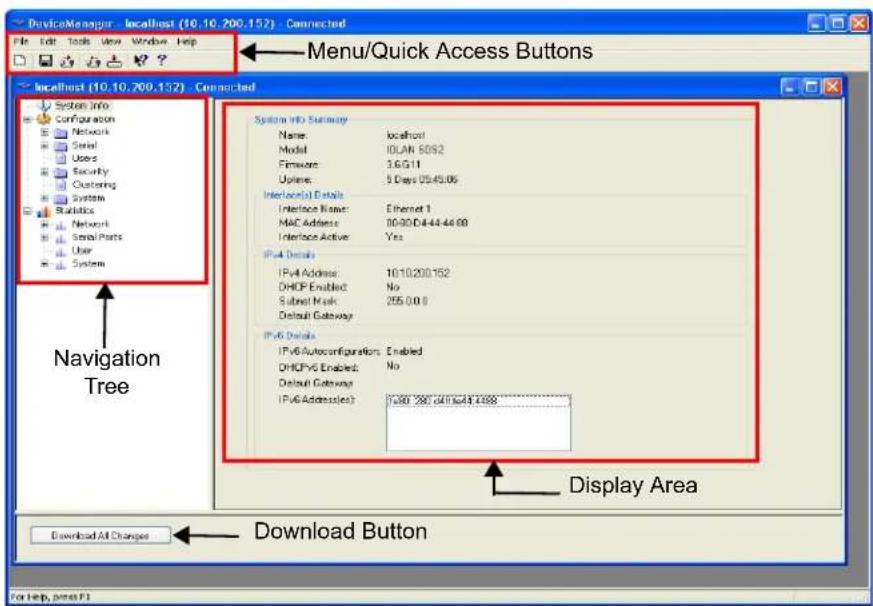
text_image
Device/Manager - localhost (10.10.200.152) - Connected File Edit Tools View Window Help Menu/Quick Access Buttons localhost (10.10.700.152) - Connected System Info Configuration Network Serial Users Security Clustering System Statistics Network Serial Parts User System System Info Summary Name localhost Model 10LAN 8092 Firmware 3.GG11 Updates 5 Days 05:45:06 Interpersonal Details Interface Name Ethernet 1 MAC Address 00-90-D4-44-44-99 Interface Active Yes IPv4 Details IPv4 Address: 1010.200.152 DHCP Enabled: No Submit Mask: 255.0.0.0 Default Gateway IPv6 Details IPv6 Autoconfigurations Enabled DHCPY6 Enabled: No Default Gateway IPv6 Address(es): 1000 200 6410x44 4499 Display Area Download All Changes Download Button For help, press F1Navigating the Options
The left-hand navigation tree allows you to quickly and easily navigate the various Configuration and Statistics pages of DeviceManager. Further navigation is available in the form of buttons and tabs in the display area of DeviceManager, depending on where you are in the navigation tree, as shown in the below.
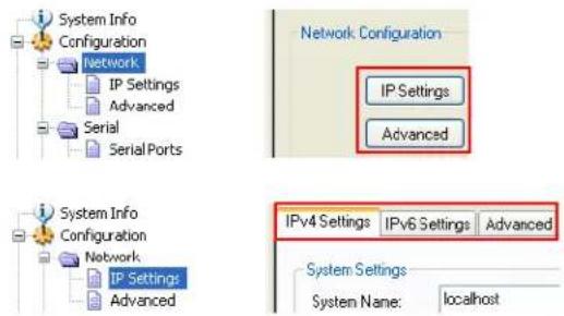
text_image
System Info Configuration Network IP Settings Advanced Serial Serial Ports Network Configuration IP Settings Advanced System Info Configuration Network IP Settings Advanced IPv4 Settings | IPv6 Settings | Advanced System Settings System Name: localhostNotice that when you expand a parent node in the tree (e.g., Serial), the tree displays the same options that appear as buttons in the display area, as shown below. This gives you the choice of using the navigation tree or buttons to navigate the options.
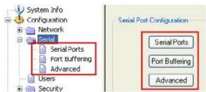
text_image
System Info Configuration Network Serial Serial Ports Port Buffering Advanced Users Security Serial Port Configuration Serial Ports Port Buffering AdvancedDownloading the Configuration
When you have completed all your configuration changes, click the Download All Changes button to download the configuration to the IOLAN. You must reboot the IOLAN for your configuration changes to take effect.
WebManager
Overview
The WebManager is a web browser-based method of configuring/managing the IOLAN. It follows the same design as the DeviceManager, so it is easy to switch between the WebManager and DeviceManager when configuring your IOLAN. See Chapter 5, Using DeviceManager and WebManager for information on configuring/managing the IOLAN with DeviceManager.
Access Platforms
You can access the IOLAN through WebManager from any system that can run a web browser. WebManager can be accessed by the admin user or any user who has Admin Level privileges.
Features
WebManager supports the following features:
- The ability to open a session to the IOLAN and download a (saved) configuration file to it.
- The ability to save a configuration file locally in text format, in addition to the binary format.
- The ability to download/upload keys/certificates to/from the IOLAN.
- The ability to download custom files, such as new terminal definitions and a custom language files to the IOLAN.
- From WebManager, you can launch EasyPort Web, which can be used to:
- access clustered IOLANs
- access ports configured with the Console Management profile and launch an SSH or Telnet session to those console ports
• exercise power management capability (when using the Perle Remote Power Switch)
Connecting to the IOLAN Using WebManager
Before you can connect to the IOLAN using WebManager, the IOLAN must already be configured with a known IP address; see Setting Up the Network to configure an IP address on your IOLAN.
To connect to the IOLAN through the WebManager:
-
Open your web browser and type in the IP address of the IOLAN that you want to manage/configure and press Enter; for example: http://123.123.123.123.
-
If you successfully connect to the IOLAN, a login screen will appear.
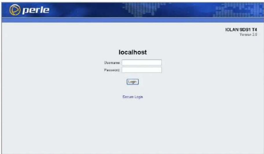
text_image
IOLAN SDS1 T4 Version 3.6 localhost Username: Password: Login Secure Login- If you are accessing the IOLAN in non-secure HTTP, just type in the username "admin" and the associated password (the factory default password is superuser) If the IOLAN has already been configured for secure access mode (HTTPS), select the Secure Login link and then type in the username "admin" and the associated password.
The secure HTTP (HTTPS) mode requires that the SSL Passphrase is already defined in the IOLAN configuration and the SSL/TLS certificate/private key and CA list must have already been downloaded to the IOLAN; see Keys and Certificates for more information.
Using WebManager
After you have successfully logged into WebManager, you will see the following:
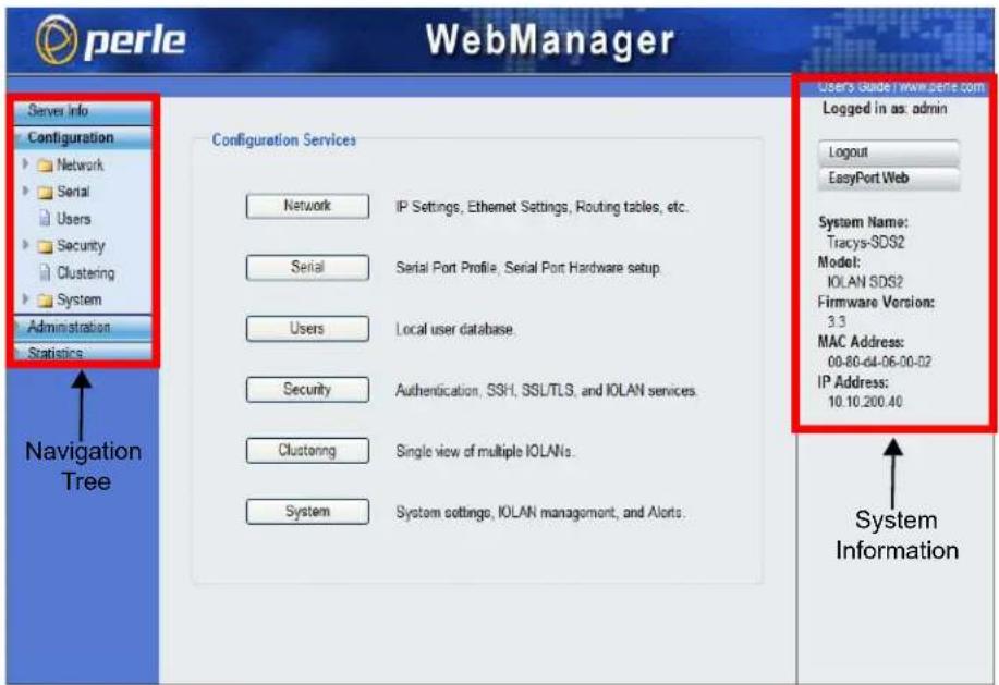
text_image
Perle WebManager Servers Info Configuration Network Serial Users Security Clustering System Administration Statistics Navigation Tree Configuration Services Network IP Settings, Ethernet Settings, Routing tables, etc. Serial Serial Port Profile, Serial Port Hardware setup. Users Local user database. Security-Augustentication, SSH, SSL/TLS, and IOLAN services. Clustering Single view of multiple IOLANs. System System settings, IOLAN management, and Alerts. Users Guide: www.sene.com Logged in as: admin Logout EasyPort Web System Name: Tracys-SDS2 Model: IOLAN SDS2 Firmware Version: 3.3 MAC Address: 00-80-d4-06-00-02 IP Address: 10.10.200.40 System InformationYou navigate through the different configuration windows by selecting an option in the left-hand navigation tree. When you click on an option that is under a folder, more navigation options are displayed:

text_image
Server Info Configuration Network IP Address Advanced IP Settings Advanced Navigation Tabs IP Settings System Name: localhostThe Network folder contains two configuration options, IP Address and Advanced. Notice that when the IP Address option is selected, there are more navigation options in the form of the tabs, IP Settings and Advanced.
Remember that in the WebManager, it is necessary to press the Apply button to save your changes.
Command Line Interface
Overview
The Command Line Interface (CLI) is a command line option for IOLAN configuration/management. See the Command Line Interface Reference Guide for a full breakdown of all the CLI commands and their functionality.
Access Platforms
The CLI is accessed by any application that supports a Telnet or SSH session to the IOLAN's IP address, such as Putty, SecureCRT, or from a command prompt. You can also access the CLI from a dumb terminal or PC connected to a serial port.
Features
The CLI supports the following features:
- You can access the IOLAN from any application that supports Telnet or SSH.
- The ability to clear the ARP table (cache).
- The ability to save a configuration file locally in text format, in addition to the binary format.
- For existing IOLAN+ customers, the native IOLAN+ CLI to be used by entering the iolan+ command. See your IOLAN User's Guide for information on using the IOLAN+ CLI.
The IOLAN+ CLI is not supported on IOLAN models with more than 16 ports or the DS1/TS2 and medical unit models.
Connecting to the IOLAN Using the CLI
There are two ways you can access the IOLAN, through the network (Ethernet connection) or through the serial connection. If you are accessing the IOLAN through the network, the IOLAN must already have a known IP address configured; see Using a Direct Serial Connection to Specify an IP Address for information on configuring an IP address.
Through the Network
To connect to the IOLAN through the network to configure/manage it using the CLI, do the following:
- Start a Telnet or SSH session to the IOLAN's IP address; for example:
telnet 10.10.201.100 - You will get a Login: prompt. You can login as the admin user or as a user with Admin Level rights. If the login is successful, you will get a prompt that displays the IOLAN model and number of ports:
Login: admin Password:
SDS2#
You will see a prompt that displays the model and number of the IOLAN. You are now ready to start configuring/managing your IOLAN using the CLI.
Through the Serial Port
To connect to the IOLAN through the serial port to configure/manage it using the CLI (or Menu), see Using a Direct Serial Connection to Specify an IP Address.
After you have established a connection to the IOLAN, you will get a Login: prompt. You can login as the admin user or as a user with Admin Level rights. If the login is successful, you will get a prompt that displays the IOLAN model and number of ports:
Login: admin
Password:
SDS2#
You will see a prompt that displays the model and number of the IOLAN. You are now ready to start configuring/managing your IOLAN using the CLI
Using the CLI
After you have successfully logged in, you can start configuring/managing the IOLAN by typing in commands at the prompt. If you are not sure what commands are available, you can type a ? (question mark) at any time during a command to see your options.
See the Command Line Interface Reference Guide for more information about the CLI.
Menu
Overview
The Menu is a graphical representation of the CLI. You can look up Menu parameter explanations in the Command Line Interface Reference Guide. The only operations that the Menu does not support are the downloading and uploading of files to/from the IOLAN.
Access Platforms
The Menu is accessed by any application that supports a Telnet or SSH session to the IOLAN's IP address, such as Putty, SecureCRT, or from a command prompt. You can also access the Menu from a dumb terminal or PC connected to a serial port.
Features
The Menu supports the following features:
- You can access the IOLAN from any application that supports Telnet or SSH.
- For existing IOLAN+ customers, the native IOLAN+ menu interface can be used by entering the iolan+ command to display and use the native IOLAN+ menu interface. See your IOLAN User's Guide for information on using the IOLAN+ interface. See IOLAN+ Interface for more information about IOLAN+ interface.
Connecting to the IOLAN Using the Menu
To connect the IOLAN using the Menu, follow the directions for Connecting to the IOLAN Using the CLI.
Using the Menu
After you have successfully logged in, type screen at the prompt and press Enter. You will be asked to enter a terminal type, and then you will see the following Menu:
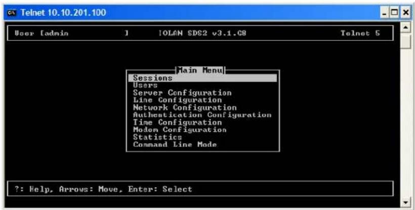
text_image
Telnet 10.10.201.100 User [admin] 1 IOLAN SDC2 v3.1.C8 Telnet 5 Main Menu Sessions Users Server Configuration Line Configuration Network Configuration Authentication Configuration Time Configuration Modem Configuration Statistics Command Line Mode ?: Help, Arrows: Move, Enter: SelectTo navigate through the Menu options, do the following:
-
Highlight a Menu option by using the keyboard up and down arrows to navigate the list.
-
When the Menu item you want to access is highlighted, press the Enter key to either get to the next list of options or to get the configuration screen, depending on what you select.
-
When you are done configuring parameters in a screen, press the Enter key and then the Enter key again to Accept and exit the form.
-
If you want to discard your changes, press the Esc key to exit a screen, at which point you will be prompted with Changes will be lost, proceed? (y/n), type y to discard your changes or n to return to the screen so you can press Enter to submit your changes.
-
If there are a number of predefined options available for a field, you can scroll through those items by pressing the Space Bar or you can type 1 (lowercase L) to get a list of options, use the up/down arrows to highlight the option you want, and then press Enter to select it.
DHCP/BOOTP
Overview
Several IOLAN parameters can be configured through a DHCP/BOOTP server during the IOLAN bootup. This is particularly useful for configuring multiple IOLANs.
Not all configuration parameters are supported in the DHCP/BOOTP configuration (see DHCP/BOOTP Parameters for supported configuration parameters), so you will need to use another configuration method, such as DeviceManager, WebManager or CLI, to complete the configuration.
Features
DHCP/BOOTP supports the following features:
- DHCP/BOOTP can supply the IOLAN's IP address.
- The DHCP/BOOTP server can configure certain server and user configuration parameters when the IOLAN is booted.
- The DHCP/BOOTP server can auto-configure the IOLAN with basic setup information (IP address, subnet/prefix bits, etc.).
- The DHCP/BOOTP server can download a new version of firmware when the IOLAN is rebooted.
- The DHCP/BOOTP server can download a full configuration file when the IOLAN is rebooted.
Connecting to the IOLAN Using DHCP/BOOTP
The IOLAN will automatically request an IP address from the DCHP/BOOTP server when the Obtain IP address automatically using DHCP/BOOTP parameter is enabled. To enable the Obtain IP address automatically using DHCP/BOOTP parameter, follow the directions in Using a Direct Serial Connection to Enable BOOTP/DHCP.
Using DHCP/BOOTP
To use DHCP/BOOTP, edit the bootp file with IOLAN configuration parameters. You can use DHCP/BOOTP to perform the following actions on a single or multiple IOLANs on bootup:
- auto-configure with minimal information; for example, only an IP address
- auto-configure with basic setup information (IP address, subnet/prefix bits, etc.)
- download a new version of firmware
- download a full configuration file
DHCP/BOOTP is particularly useful for multiple installations: you can do all the IOLANs' configuration in one DHCP/BOOTP file, rather than configure each IOLAN manually. Another advantage of DHCP/BOOTP is that you can connect the IOLAN to the network, turn on its power and let autoconfiguration take place. All the configuration is carried out for you during the DHCP/BOOTP process.
DHCP/BOOTP Parameters
The following parameters can be set in the DHCP/BOOTP bootp file:
- SW_FILE—The full path, pre-fixed by hostname/IP address (IPv4 or IPv6), and file name of the firmware update.
- CONFIG_FILE—The full path, pre-fixed by hostname/IP address (IPv4 or IPv6), and file name of the configuration file.
- GUI_ACCESS—Access to the IOLAN from the HTTP or HTTPS WebManager. Values are on or off.
- AUTH_TYPE—The authentication method(s) employed by the IOLAN for all users. You can specify the primary and secondary authentication servers, separated by a comma. This uses the following numeric values for the authentication methods.
- 0 —None (only valid for secondary authentication)
- 1 —Local
- 2 —RADIUS
- 3 —Kerberos
- 4 —LDAP/Microsoft Active Directory
- 5 —TACACS+
- 6 —SECURID
- 7 —NIS
- SECURITY—Restricts IOLAN access to devices listed in the IOLAN's host table. Values are yes or no.
- TFTP_RETRY—The number of TFTP retries before aborting. This is a numeric value, for example, 5.
- TFTP_TMOUT—The time, in seconds, before retrying a TFTP download/upload. This is a numeric value, for example, 3.
- CUSTOM_LANG—The full path, pre-fixed by a hostname/IP address (IPv4 or IPv6), and file name of a translated language file. For example, 192.101.34.211 /accounting/Iolan_ds_german.txt.
- EXTRA_TERM1—(EXTRA_TERM2, EXTRA_TERM3) The full path, pre-fixed by a hostname/IP address (IPv4 or IPv6), and file name of a termcap file for a specific terminal type.
SNMP
Overview
The IOLAN supports configuration and management through SNMP. SNMP Management tools (SNMP client/MIB browser software) can be used to set IOLAN configuration parameters and/or view IOLAN statistics.
Before you can configure/manage the IOLAN using SNMP, you need to set the IOLAN IP address and configure a read-write user for SNMP version 3 or a community for SNMP version 1 or 2. You can use DeviceManager, CLI, or the Menu to set the IP address and user/community (don't forget to reboot the IOLAN before connecting with the SNMP manager to make your changes take effect).
Access Platforms
You can access the IOLAN SNMP MIB from any system that runs your SNMP client/MIB browser software.
Features
SNMP supports the following features:
- You can configure SNMP traps.
- Since not all versions of SNMP support secure communication, password parameters must be set using another configuration method.
Connecting to the IOLAN Using SNMP
Before you can connect to the IOLAN through an SNMP Management tool or MIB browser, you need to set the following components through another configuration method.
- Configure a known IP address on the IOLAN.
- Configure a read-write user for SNMP version 3 or a community for SNMP version 1 or 2 on the IOLAN.
- Reboot the IOLAN to make sure the changes take effect.
To connect to the IOLAN through an SNMP Management tool or MIB browser, do the following:
- Load the perle-sds.MIB file from the IOLAN CD-ROM or Perle website into your SNMP manager (this MIB works for all SDS, SCS, STS, and MDC models).
You need to have the following MIBs installed in your SNMP manager (these are usually part of the standard SNMP client/MIB browser):
SNMPv2-SMI
SNMPv2-TC
• IPV6-TC
- Verify that the read-write user for SNMP version 3 or a community for SNMP version 1 or 2 match the configuration on the IOLAN.
- Type in the IOLAN's IP address and connect to the IOLAN.
You are now ready to start configuring the IOLAN using SNMP.
Using the SNMP MIB
After you have successfully connected to the IOLAN through your SNMP Management tool or MIB browser, expand the PERLE-IOLAN-SDS-MIB folder to see the IOLAN's parameter folders. Below is an example of the configurable parameters under the ServicesInfo folder.
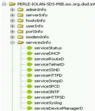
text_image
PERLE-IOLAN-SDS-MIB.iso.org.dod.int adminInfo serverInfo hostsInfo userInfo portInfo modemInfo servicesInfo serviceStatus serviceDHCP serviceRouteD serviceTelnetD serviceSSHD serviceHTTPD serviceSnmpD serviceSPCD serviceSNTP serviceHTTPSDD serviceSyslog serviceDeviceManagerDThe first variable in each folder is the Status variable, for example, serviceStatus. When you perform a GET on this variable, one of the following values will be returned:
• 1—Indicates that the container folder is active with no changes.
• 2—Indicates that the container folder is active with change(s).
Once you have completed setting the variables in a folder, you will want to submit your changes to the IOLAN. To do this, set the Status variable to 4. If you want to discard the changes, set the Status variable to 6.
4—Indicates that the changes in the container folder are to be submitted to the IOLAN.
6—Indicates that the changes in the container folder are to be discarded.
If you want to save all the changes that have been submitted to the IOLAN, you need to expand the adminInfo container folder and SET the adminFunction to 1 to write to FLASH. To make the configuration changes take effect, SET the adminFunction to 3 to reboot the IOLAN.
IOLAN+ Interface
Overview
For environments that have both IOLAN and IOLAN+ models or for users who prefer to configure using the IOLAN+ Menu or CLI, the IOLAN+ user interface is available. The IOLAN+ interface is supported on all IOLAN SDS, SCS, and STS models up to and including 16 serial ports.
Access Platforms
The Menu is accessed by any application that supports a Telnet or SSH session to the IOLAN's IP address, such as Putty, SecureCRT, or from a command prompt. You can also access the Menu from a dumb terminal or PC connected to a serial port.
Connecting to the IOLAN to Use the IOLAN+ Interface
To connect the IOLAN to using the IOLAN+ interface, follow the directions for Connecting to the IOLAN Using the CLI.
Using the IOLAN+ Interface
After you have successfully logged in to the IOLAN, you can type iolan+ at the CLI command prompt to access the IOLAN+ configuration menu (you must have User Level Normal or Admin).
The IOLAN and the IOLAN+ admin user share the same password. The default admin password is superuser (not iolan).
If you choose to use the IOLAN+ configuration interface, you should always configure the IOLAN using the IOLAN+ interface. The IOLAN/IOLAN+ fields do not map directly between the two interfaces. If you configure a field in the IOLAN configuration interface to a value that is invalid in the IOLAN+ interface and then attempt to use the IOLAN+ interface, the invalid field value will show up as ***** (all asterisks), although the IOLAN will interpret the value as valid.
Changes to the IOLAN+ Interface
You should be aware that the following IOLAN+ configuration fields are no longer supported:
- You no longer have the option of selecting access, Authentication/Logging. Also, kill, reboot, and stats are not available.
- When you select port, the following fields are not available on the Port Setup Menu:
| ** Administrator ** Hardware | PORT SETUP MENU Flow ctrl | Keys | REMOTE-ADMIN | ||||
| Speed | [9600] | Flow ctrl | [None] | Hot | [^A] | Intr | [^C] |
| Parity | [None] | Input Flow | [Enabled] | Quit | [^]] | Kill | [^\] |
| Bit | [8] | Output Flow | [Enabled] | Del | [^H] | Sess | N/A |
| Stop | [1] | Echo | [^E] | ||||
| Break | [Disabled] | IP Addresses | |||||
| Monitor DSR | [No] | Src | [ ] | Mask | [ | ] | |
| Monitor DCD Interface | [No][EIA-232] | Dst | [ ] | ||||
| User | Options | Access | [Local] | ||||
| Name [abcd] | Keepalive | [No] | UDP Retries | N/A | |||
| Terminal type [dumb] | Rlogin/Telnet | N/A | Retry Interval | N/A | |||
| TERM [ | Debug options | N/A | Authentication | N/A | |||
| Video pages [5] | Map CR to CR LF | [No] | Mode | [Raw] | |||
| CLI/Menu [CLI] | Hex data | N/A | Connection | [None] | |||
| Reset Term [No] | Secure | N/A | Host | ] | |||
| MOTD | [Yes] | Remote Port | [0] | ||||
| Local Port | [10001] | ||||||
- User, Name—only when using LPD/LPR, Name no longer is used as the queue name
- Options, Rlogin/Telnet
- Options, Debug options
- Options, Hex data
- Options, Secure
- Keys, Sess
- Access, UDP Retries
- Access, Retry Interval
- Access, Authentication
- When you select line, Access, the following fields are not available on the Access Menu:
| ** Administrator ** TTY Name Access Authentication Mode UDP Retries Interval | |||||||
| 1 | [abcd] | [Local] | N/A | [Raw] | N/A | N/A | |
| 2 | [abcdef] | [Local] | N/A | [Raw] | N/A | N/A | |
- Authentication
- UDP Retries
- Interval
- When you select line, Options, the following fields are not available on the Options Menu:
| ** Administrator ** | OPTIONS MENU | REMOTE-ADMIN | ||||
| TTY | Opt | CR | HEX | Rlogin/Telnet | Keepalive | |
| 1 | N/A | [No] | N/A | N/A | [No] | |
| 2 | N/A | [No] | N/A | N/A | [No] | |
Opt
HEX
• Rlogin/Telnet
- When you select access, Remote access sites., the following fields are not available on the Remote Access Systems Screen:
** Administrator ** REMOTE ACCESS SYSTEMS SCREEN REMOTE-ADMIN
Sitename [ ]
User name [ ]
Password [ ]
Device type ( )
Service type N/A
Inactivity N/A
Phone number [ ]
Login-script N/A
• Service type
- Inactivity
- Login-script
- When you select access, Remote site devices., the following fields are not available on the Remote Site Device Screen:
** Administrator ** REMOTE SITE DEVICES SCREEN REMOTE-ADMIN
Type [ ]
IP Addresses
Src Addr N/A
Dst Addr N/A
Modem
Config [ ]
Dial Comm N/A
Hang Up N/A
PPP Configuration Dialer Configuration
Restart timer [3] Dial Timeout [45]
Max Retries [10] Dial Retries [2]
Inactivity [0 ]
• IP Address, Src Address
• IP Address, Dst Address
• Modem, Dial Comm
- Modem, Hang Up
When you select server, the following fields are not available on the Server Configuration menu:
| ** Administrator ** | SERVER CONFIGURATION | REMOTE-ADMIN | ||
| Name | [wchiewsds2] | Debug mode | N/A | |
| IP address | [172.16.22.7] | |||
| Subnet mask | [255.255.0.0] | |||
| Ethernet address | (00:80:d4:88:88:88) | Ethernet speed [AUTO] | ||
| Language | [English] | |||
| Identification | [ | ] | ||
| Lock | [Disabled] | |||
| Password limit | [3] | |||
| CR to initiate | N/A | |||
| SNAP encoding | N/A | |||
| Boot host | [ | ] Boot diagnostics | N/A | |
| Boot file | [ | |||
| Init file | [ | |||
| MOTD file | [ | |||
| Domain name | [ | ] | ||
| Name server | [ ] | NS Port | N/A | |
| WINS server | [ ] | |||
- Debug mode
- CR to initiate
- SNAP encoding
- Boot diagnostics
NS Port
A new parameter was added, Interface, to the to Port Setup Menu, to specify whether you are setting up the serial line as a EIA-232 or EIA-422 line.

text_image
4Getting Started
Introduction
There are several different configuration methods available to configure the IOLAN (see Chapter 3, Configuration Methods for more information). This chapter describes the three main minimal configuration requirements for the IOLAN through either Easy Config Wizard (cannot configure users using this method), DeviceManager, or WebManager:
If you are setting up the IOLAN medical unit (MDC) model, you must first install the latest firmware to take advantage of the full feature set available with the MDC model. The latest firmware can be found either on the CD-ROM that came with the IOLAN or on the Perle website, www.perle.com/downloads (when you access the webpage, select your specific IOLAN model). See Downloading IOLAN Firmware for information on how to download the latest IOLAN firmware.
- Setting up the network—This minimally consists of configuring an IP address or enabling DHCP/BOOTP. Once the IOLAN has an IP address, you can use any configuration method.
- Setting up the serial ports—You will want to select the serial port profile that matches the serial port requirement/scenario for your serial device.
- Setting up users—This is an optional step, which is only required when your implementation requires users to access the IOLAN and you are not using external authentication.
Easy Configuration Wizard
The Easy Config Wizard quickly sets up the IOLAN's network configuration and all serial ports to one of the following:
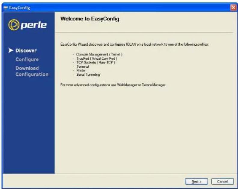
text_image
EasyConfig Welcome to EasyConfig EasyConfig Wizard discovers and configures IOLAN on a local network to one of the following profiles: - Console Management ( Telnet ) - TruePort ( Virtual Com Port ) - TCP Sockets ( Raw TCP ) - Terminal - Printer - Serial Tunneling For more advanced configurations use WebManager or DeviceManager. Next > Cancel- Console Management—Allows users on the network to connect to a serial device that is connected to a serial port on the IOLAN.
- TruePort (Virtual COM Port)—Allows a networked system to communicate with your serial device through a virtual COM or TTY port, using the Perle TruePort software.
- TCP Sockets (Raw TCP)—Allows hosts on the network to communicate with a serial device that requires raw data throughput (such as a printer or card reader) connected to the IOLAN serial port.
- Terminal—Allows a terminal device to connect to a specified host on the network through a serial port on the IOLAN.
- Printer—Allows hosts on the network to talk to a printer using LPD connected to the IOLAN.
- Serial Tunneling—Allows IOLANs on the network to establish a virtual link between their serial ports. Typically, one IOLAN's serial port is configured as a Tunnel Server and the other IOLAN's serial port is configured as a Tunnel Client.
Setting Up the Network
The most important part of setting up the network is assigning an IP address to the IOLAN, whether this is a static IP address or enabling a DHCP/BOOTP-assigned IP address. You should also assign a name to the IOLAN, to make it easier to recognize. This section deals primarily with setting the IP address.
Using DeviceManager
To use the DeviceManager, you must first install it on a Windows ^® operating system. The DeviceManager is able to automatically discover all IOLANs on your local network, even if they have not yet been assigned an IP address. If routers on the network have been setup to propagate multicasts, DeviceManager will also be able to discover IOLANs in other networks. The DeviceManager installation wizard can be found on the CD-ROM included in the IOLAN package.
- Connect the IOLAN to the network.
- Power on the IOLAN.
- From the CD-ROM that was included in the IOLAN packaging, select the DeviceManager link.
- Click on the link under Location and click Open to automatically start the DeviceManager installation.
- Install the DeviceManager by following the installation wizard. On the last window, check the Yes, I want to launch DeviceManager now. box and click the Finish button.
- When you launch the DeviceManager, it will automatically scan the local network and display any IOLANs that it can find.
- Any IOLAN that does not have an IP address will be displayed as Not Configured, with the Model and MAC Address to identify the IOLAN. Highlight the IOLAN that you want to assign an IP address to and click the Assign IP button.
-
Choose the method you want to use to assign an IP address to the IOLAN:
-
Type in the IP address that you want to assign to this IOLAN.
- Enable the Have the IOLAN automatically get a temporary IP address option. This will turn on DHCP/BOOTP, so the IOLAN will attempt to get its IP address from your DHCP/BOOTP server. If you don't have a DHCP/BOOTP server, DeviceManager will temporarily assign an IP address in the range of 169.254.0.1-169.254.255.255 that will be used only for the duration of the DeviceManager/IOLAN communication.
Click the Assign IP button.
- You are now ready to configure the IOLAN. Double-click the IOLAN you just configured IP address for to open a configuration session. Type superuser (the factory default admin user password) in the Login window and click OK.
- Expand the Server Configuration folder and select Server. Verify the IP address configuration. You should also enter a name in the Server Name field to make the IOLAN easily identifiable.
- To make your edits take effect, you need to download the new configuration file and then reboot the IOLAN. Download the configuration file to the IOLAN by selecting Tools, Download Configuration to Unit or click the Download All Changes button.
- Reboot the IOLAN by selecting Tools, Reboot Server or click the Reboot IOLAN button.
For more information on configuring the IOLAN using DeviceManager, see Chapter 5, Using DeviceManager and WebManager.
Using WebManager
To use the WebManager as your configurator, you must first assign an IP address to the IOLAN. You can use the Easy Config Wizard to assign an IP address to the IOLAN or any of the other methods described in this section. Once the IP address is assigned to the IOLAN, simply type the IP address into the Address field of your web browser and press the Enter key.
Using a Direct Serial Connection to Specify an IP Address
You can connect to the IOLAN's serial console port using a PC with a terminal emulation package, such as HyperTerminal or a terminal.
This procedure does not apply to IOLAN medical unit models.
- Connect the IOLAN to your PC or dumb terminal. Make sure the DIP switch is in Console mode (for desktop models, this sets the IOLAN serial port 1 to EIA-232) or that you are connected to the dedicated Console port (for rack mount models). When connecting a terminal or PC directly (without modems), the EIA-232 signals need to be crossed over ('null modem' cable). See Appendix D, EIA-232 Cabling Diagrams for cabling diagrams.
- Using a PC emulation application, such as HyperTerminal, or from a dumb terminal, set the Port settings to 9600 Baud, 8 Data bits, No Parity, 1 Stop Bits, and No Hardware Flow control to connect to the IOLAN. You can change these settings for future connections on the rack mount models (the IOLAN must be rebooted for these changes to take place).
- When prompted, type admin for the User and superuser for the Password. You should now see the a prompt that displays the model type and port number; for example, SCS16#.
- You are now logged into the IOLAN and can set the IP address by typing from the command line using the Command Line Interface (CLI).
For single Ethernet connection models, type:
set server internet
For dual Ethernet connection (SCS) models, type:
set server internet eth1
For wireless connection (W) models, type:
set server internet wan0
Where ipv4address is the IP Address being assigned to the IOLAN.
- Type the following command:
save
-
If you are going to use another configuration method, such as WebManager or DeviceManager, unplug a desktop IOLAN or turn Off a rack mount IOLAN. On a desktop IOLAN, change the DIP switch to Off Serial (DIP switch in the up position) and connect it to your serial device. Plug the IOLAN back in, automatically rebooting the IOLAN in the process.
-
If you want to complete the configuration using a direct connection, see Command Line Interface and/or Menu. After you complete configuring the IOLAN, unplug the IOLAN. If this is a desktop model, change the IOLAN DIP switch to Off Serial (DIP switch in the up position) and connect it to your serial device. Plug the IOLAN back in, automatically rebooting the IOLAN in the process.
Using a Direct Serial Connection to Enable BOOTP/DHCP
If you are using BOOTP, you need to add an entry in the BOOTP server for the IOLAN that associates the MAC address (found on the back of the IOLAN) and the IP address that you want to assign to the IOLAN. After you have made the MAC address/IP address association for BOOTP, use the following directions for BOOTP or DHCP.
You can connect to the IOLAN using a PC with a terminal emulation package, such as HyperTerminal or a dumb terminal.
This procedure does not apply to IOLAN medical unit models.
- Connect the IOLAN to your PC or dumb terminal. Make sure the DIP switch is in Console mode (for desktop models, this sets the IOLAN serial port to EIA-232) or that you are connected to the dedicated Console port (for rack mount models). When connecting a terminal or PC directly (without modems), the EIA-232 signals need to be crossed over ('null modem' cable). See Appendix D, EIA-232 Cabling Diagrams for cabling diagrams.
- Using a PC emulation application, such as HyperTerminal, or from a dumb terminal, set the Port settings to 9600 Baud, 8 Data bits, No Parity, 1 Stop Bits, and No Hardware Flow control to connect to the IOLAN. You can change these settings for future connections on the rack mount models (the IOLAN must be rebooted for these changes to take place).
- When prompted, type admin for the User and superuser for the Password. You should now see the a prompt that displays the model type and port number; for example, SCS16#.
-
You are now logged into the IOLAN and can set the IP address by typing from the command line using the Command Line Interface (CLI). Type the following command:
set server internet dhcp/bootp on -
Type the following command:
save
- Type the following command:
reboot
-
When the IOLAN reboots, it will automatically poll for an IP address from the DHCP/BOOTP server. If the IOLAN has dual Ethernet, each Ethernet connection will automatically be assigned an IP address, you can access the IOLAN through either IP address.
-
To view the DHCP/BOOTP assigned IP address, type the following command:
show interface ethernet
If for some reason it cannot obtain an IP address from your DHCP/BOOTP server, you will have to either reconnect to the IOLAN on the console port and reboot it or push the RESET button to access the IOLAN.
You are now ready to configure the IOLAN. See Chapter 3, Configuration Methods for information on the different IOLAN configuration methods.
Using ARP-Ping
You can use the ARP-Ping (Address Resolution Protocol) method to temporarily assign an IP address and connect to your IOLAN to assign a permanent IP address. To use ARP-Ping to temporarily assign an IP address:
- From a local UNIX/Linux host, type the following at the system command shell prompt:
arp -s a.b.c.d aa:bb:cc:dd:ee:ff
On a Windows ^® 2000 or newer system, type the following at the command prompt:
arp -s a.b.c.d aa-bb-cc-dd-ee-ff
(where a.b.c.d is the IPv4 address you want to temporarily assign to the IOLAN, and
aa:bb:cc:dd:ee:ff is the Ethernet (MAC) address of IOLAN (found on the back of the unit).
- Whether you use UNIX or Windows ^ , you are now ready to ping to the IOLAN. Here is a UNIX example of the sequence to use:
arp -s 192.168.209.8 00:80:d4:00:33:4e
ping 192.168.209.8
From the ping command issued in step 2, the IOLAN will pickup and use the IP address entered into the ARP table in step 1. You are now ready to configure the IOLAN. See Chapter 3, Configuration Methods for information on the different IOLAN configuration methods.
For an IPv6 Network
The IOLAN has a factory default link local IPv6 address based upon its MAC Address. For example, the link local address is:
IOLAN MAC Address: 00-80-D4-AB-CD-EF
Link Local Address: fe80::0280:D4ff:feAB:CDEF
By default, the IOLAN will listen for IPV6 router advertisements to obtain additional IPV6 addresses. No configuration is required, however, you can manually configure IPV6 addresses and network settings; see Chapter 6, Network Settings for more information on IPv6 configuration options.
You are now ready to configure the IOLAN. See Chapter 3, Configuration Methods for information on the different IOLAN configuration methods.
Setting Up the Serial Port(s)
The DeviceManager and WebManager have the following serial port profiles that will simplify serial port setup:
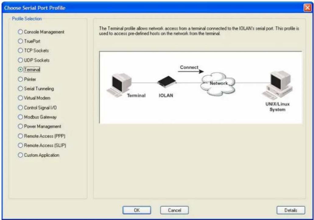
text_image
Choose Serial Port Profile Profile Selection Console Management TruePort TCP Sockets UDP Sockets Terminal Printer Serial Tunneling Virtual Modem Control Signal I/O Modbus Gateway Power Management Remote Access (PPP) Remote Access (SLIP) Custom Application The Terminal profile allows network access from a terminal connected to the IOLAN's serial port. This profile is used to access pre-defined hosts on the network from the terminal. Terminal IOLAN Connect Network UNIX/Linux System OK Cancel Details- Console Management—The Console Management profile configures a serial port to provide network access to a console or administrative port. This profile sets up a serial port to support a TCP socket that listens for a Telnet or SSH connection from the network.
- TruePort—The TruePort profile configures a serial port to connect network servers or workstations running the TruePort software to a serial device as a virtual COM port. This profile is ideal for connecting multiple serial ports to a network system or server.
- TCP Sockets—The TCP Sockets profile configures a serial port to allow a serial device to communicate over a TCP network. The TCP connection can be configured to be initiated from the network, a serial device connected to the serial port, or both. This is sometimes referred to as a raw connection or a TCP raw connection.
- UDP Sockets—The UDP Sockets profile configures a serial port to allow communication between the network and serial devices connected to the IOLAN using the UDP protocol.
- Terminal—The Terminal profile configures a serial port to allow network access from a terminal connected to the IOLAN's serial port. This profile is used to access predefined hosts on the network from the terminal.
- Printer—The Printer profile configures a serial port to support a serial printer that can be accessed by the network.
-
Serial Tunneling—The Serial Tunneling profile configures a serial port to establish a virtual link over the network to a serial port on another IOLAN. Both IOLAN serial ports must be configured for Serial Tunneling (typically one serial port is configured as a Tunnel Server and the other serial port as a Tunnel Client).
-
Virtual Modem—The Virtual Modem (Vmodem) profile configures a serial port to simulate a modem. When the serial device connected to the IOLAN initiates a modem connection, the IOLAN starts up a TCP connection to another IOLAN configured with a Virtual Modem serial port or to a host running a TCP application.
- Control Signal I/O—The Control Signal I/O profile enables the use of the EIA-232 serial port signal pins to be used as assigned Digital Inputs or Digital Outputs.
- Modbus Gateway—The Modbus Gateway profile configures a serial port to act as a Modbus Master Gateway or a Modbus Slave Gateway.
- Power Management—The Power Management profile configures a serial port to communicate with a Remote Power Switch's (RPS) administration port. This allows network access to the RPS and permits access to statistics and control of the RPS's power plugs.
- Remote Access (PPP)—The Remote Access (PPP) profile configures a serial port to allow a remote user to establish a PPP connection to the IOLAN's serial port. This is typically used with a modem for dial-in or dial-out access to the network.
- Remote Access (SLIP)—The Remote Access (SLIP) profile configures a serial port to allow a remote user to establish a SLIP connection to the IOLAN's serial port. This is typically used with a modem for dial-in or dial-out access to the network.
- Custom Application/Plugin—The Custom Application/Plugin profile configures a serial port to run a custom application or IOLAN plugin. After you download the custom application files and specify the application name and any parameters you want to pass to it, the IOLAN will execute the application when the serial port is started.
Each serial port profile contains all the parameters that are required to completely configure the serial port scenario represented by the profile.
To select a serial port profile in the DeviceManager, connect through the DeviceManager to the IOLAN you are configuring and select Serial, Serial Ports in the navigation pane. Highlight the serial port you want to configure and then click Edit.
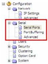
text_image
Configuration Network IP Settings Advanced Serial Serial Ports Port Buffering Advanced Users Security Clustering Option Cord System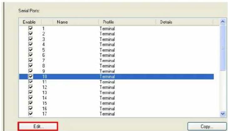
text_image
Serial Ports: Enable Name Profile Details ✓ 1 Terminal ✓ 2 Terminal ✓ 3 Terminal ✓ 4 Terminal ✓ 5 Terminal ✓ 6 Terminal ✓ 7 Terminal ✓ 8 Terminal ✓ 9 Terminal ✓ 10 Terminal ✓ 11 Terminal ✓ 12 Terminal ✓ 13 Terminal ✓ 14 Terminal ✓ 15 Terminal ✓ 16 Terminal ✓ 17 Terminal Edit... Copy...When the default serial port profile Terminal displays, click the Change Profile button and select the appropriate profile for the serial port. See Chapter E, Configuring Serial Ports for more information on the serial port profiles and their configuration parameters.
Setting Up Users
When you have a user who is accessing a device connected to a serial port from the network or who is accessing the network from a device connected to a serial port through the IOLAN, you can create a user account and configure the user's access privileges. Notice that there is a Default user; the Default user's parameters are inherited by users logging into the IOLAN who are being authenticated by an external authentication method (see Authentication for more information) or are accessing the IOLAN as a Guest (see Local for more information).
To add a user account, click on the Users page in the navigation pane.
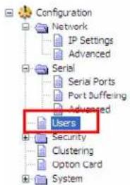
text_image
Configuration Network IP Settings Advanced Serial Serial Ports Port Buffering Advanced Users Security Clustering Option Card System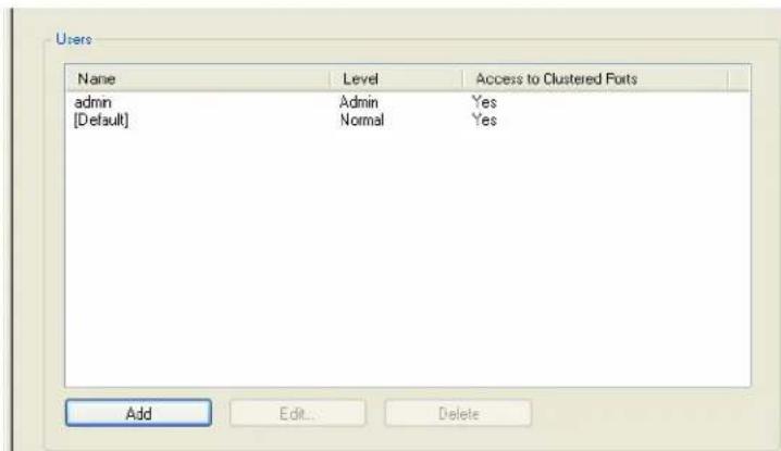
text_image
Users Name Level Access to Clustered Ports admin Admin Yes [Default] Normal Yes Add Edit... DeleteClick the Add button to create a user account.
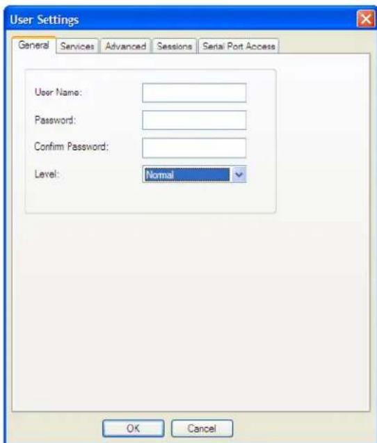
text_image
User Settings General Services Advanced Sessions Serial Port Access User Name: Password: Confirm Password: Level: Normal OK CancelTo quickly add a user, fill out the field in the General tab and click OK.
See Chapter 7, Configuring Users for more information about the other user parameters you can configure.

text_image
5Using DeviceManager and WebManager
Introduction
The DeviceManager and WebManager IOLAN managers have been designed to be very similar to use. DeviceManager is a Windows ^® -based application and WebManager is a browser-based application. Both options use the IOLAN's IP address to access the IOLAN; the DeviceManager can be used to assign an IP address to a new IOLAN and the WebManager requires that the IOLAN already have an IP address before it can be used to configure the IOLAN.
When using WebManager, you are required to click the Apply button each time you make a change to a configuration window/tab. In DeviceManager, you must download your configuration changes to the IOLAN either periodically or after you are done with the configuration changes. From both managers you must reboot the IOLAN in order for you configuration changes to take effect.
Navigating DeviceManager/WebManager
The DeviceManager and WebManager have very similar navigation methods. The left-hand side of the manager is the navigation tree and the center is the configuration area. The DeviceManager has menu and quick access buttons, whereas the WebManager has system information and some navigation options on the far right-hand side.
DeviceManager
The DeviceManager has a navigation tree that you can use to access the available Configuration and Statistics pages in the display area. When you select an option in the navigation tree, you can often navigate the tabs or buttons in the display area to access the various configuration and statistics options. See Using DeviceManager for more information on how to navigate the pages of DeviceManager.
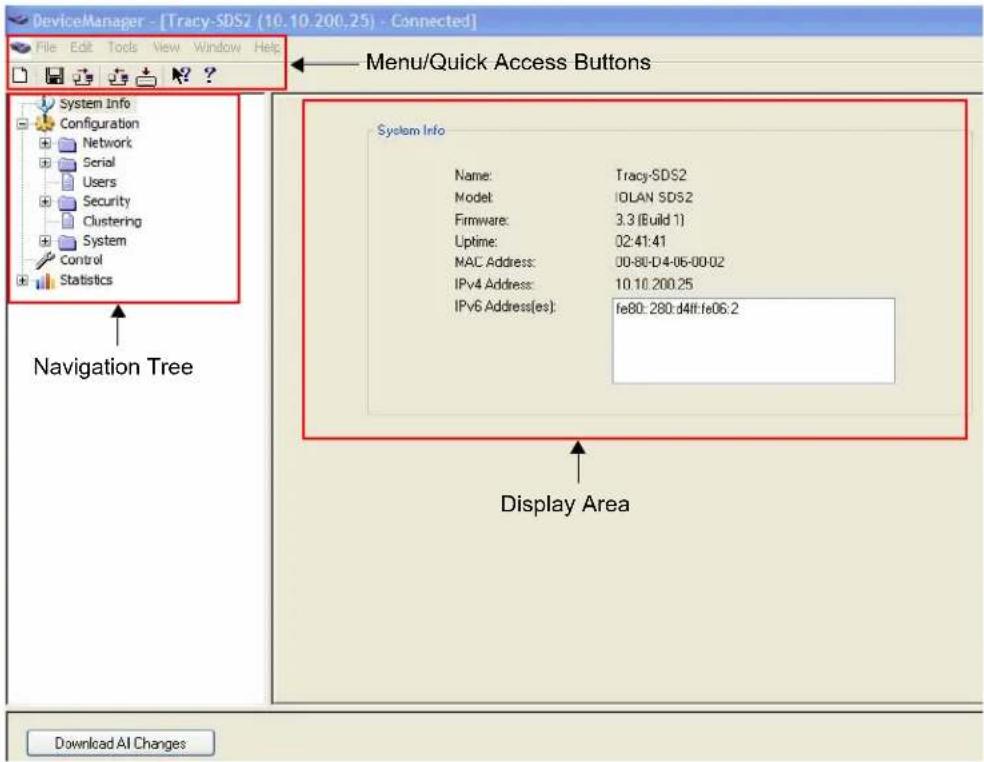
text_image
DeviceManager - [Tracy-SDS2 (10.10.200.25) - Connected] File Edit Tools View Window Help Menu/Quick Access Buttons System Info Configuration Network Serial Users Security Clustering System Control Statistics Navigation Tree System Info Name: Tracy-SDS2 Model: IOLAN SDS2 Firmware: 3.3 (Build 1) Uptime: 02:41:41 MAC Address: 00-80-D4-06-00-02 IPv4 Address: 10.10.200.25 IPv6 Address(es): fe80: 280:d4ff:fe06:2 Display Area Download All ChangesWebManager
The WebManager uses a expandable/collapsible buttons with folders and pages for the navigation tree. You can expand the buttons to view the folders and pages to see the available configuration options. When you access a configuration page, you can often navigate the tabs in the configuration area to access all of the configuration options.
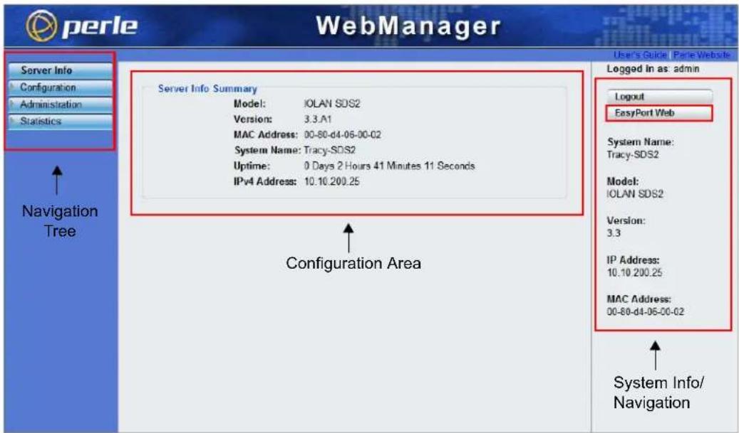
text_image
Perle WebManager Server Info Configuration Administration Statistics Server Info Summary Model: IOLAN SDS2 Version: 3.3.A1 MAC Address: 00-80-d4-06-00-02 System Name: Tracy-SDS2 Uptime: 0 Days 2 Hours 41 Minutes 11 Seconds IPv4 Address: 10.10.200.25 Configuration Area Loginout EasyPort Web System Name: Tracy-SDS2 Model: IOLAN SDS2 Version: 3.3 IP Address: 10.10.200.25 MAC Address: 00-80-d4-06-00-02 System Info/ NavigationEasyPort Web
WebManager also launches EasyPort Web, which is a browser-based management tool that can be used to manage clustered IOLANs, Remote Power Switches (RPSs), power plugs, and I/O channels (available only when an I/O model is accessed). EasyPort Web can also be launched by any user who can connect to the IOLAN through a web browser.
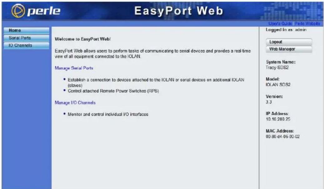
text_image
perle EasyPort Web Home Serial Ports IO Channels Welcome to EasyPort Web! EasyPort Web allows users to perform tasks of communicating to serial devices and provides a real-time view of all equipment connected to the IOLAN. Manage Serial Ports • Establish a connection to devices attached to the IOLAN or serial devices on additional IOLAN (claves) • Control attached Remote Power Switches (RPS) Manage I/O Channels • Monitor and control individual I/O interfaces User's Guide: Perle Website Logged in as admin Logout Web Manager System Name: Tracy SDS2 Model: IOLAN SDS2 Version: 3.3 IP Address: 10.10.200.25 MAC Address: 00-80-d4-06-00-02Using DeviceManager to Connect to the IOLAN
DeviceManager can connect to existing IOLANs or assign an IP address to a new IOLAN. Whenever you connect to the IOLAN through the DeviceManager, you connect as the admin user and must supply the password for the admin user.
Starting a New Session
To start a new session and connect to the IOLAN using the DeviceManager:
-
Start the DeviceManager by selecting Start, All Programs, Perle, DeviceManager, DeviceManager.
-
When the DeviceManager starts, it searches the network for IOLANs.
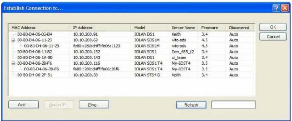
text_image
Establish Connection to... MAC Address IP Address.Model Server Name Firmware Discovered 00-80-D4-06-02-B4 10.10.200.91 IOLAN DS1 Keith 3.4 Auto 00-80-D4-06-11-23 10.10.200.69 IOLAN SDS1M vito-sds 4.5 Auto 00-80-D4-06-11-23 fe80::280:d4ff:fe06:1123 IOLAN SDS1M vito-sds 4.5 Auto 00-80-D4-06-11-87 10.10.200.152 IOLAN SDS1 Den_485_t2 3.4 Auto 00-80-D4-06-1A-90 10.10.200.143 IOLAN DS1 u_team 3.4 Auto 00-80-D4-06-28-F6 10.10.200.116 IOLAN SDS1T4.My-SDST4 3.5 Auto 00-80-D4-06-28-F6 fe80::280:d4ff:fe06:28f6 IOLAN SDS1T4.My-SDST4 3.5 Auto 00-80-D4-06-2F-51 10.10.200.33 IOLAN ST54-D Keith 3.4 Auto Add... Bsign P... Fing... RelshIf you are not seeing IPv6 addresses in the list (you must expand the entry), see IPv6 Issues to find out how to install IPv6 support.
If your IOLAN is not in the local network and you do not have a multicast enabled router in your network and therefore is not displayed in the selectable list, but can be pinged from your PC, you can add it to the selectable list by clicking the Add button.
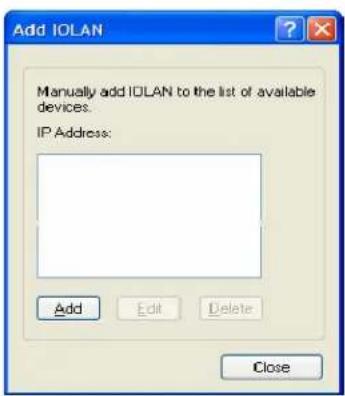
text_image
Add IOLAN Manually add IOLAN to the list of available devices. IP Address: Add Edit Delete CloseClick the Add button and type in the IOLAN's IP address; this field supports IPv4 and IPv6 addresses. Click the Close button when you have completed adding all the manual entries. Select the manually added server to connect to it.
Assigning a Temporary IP Address to a New IOLAN
You can temporarily assign an IP address to the IOLAN that is connected to your local network segment, for the purpose of connecting to it and downloading a configuration file (containing a permanent IP address). To temporarily assign an IP address to the IOLAN, do the following:
-
Click the Refresh button. The IOLAN will be displayed in the IP Address column as Not Configured.
-
Select the new IOLAN and click the Assign IP button. The following window is displayed:
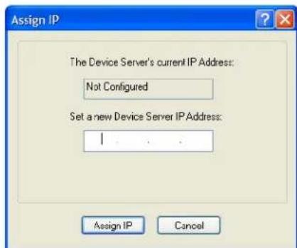
text_image
Assign IP The Device Server's current IP Address: Not Configured Set a new Device Server IP Address: I .... . . Assign IP CancelVersion 3.1 or lower
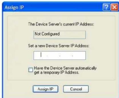
text_image
Assign IP The Device Server's current IP Address: Not Configured Set a new Device Server IP Address: I . . . Have the Device Server automatically get a temporary IP Address. Assign IP CancelVersion 3.2 or higher
-
Type a valid temporary IP address into the address field or, in version 3.2 or higher, enable the Have the IOLAN automatically get a temporary IP address. If you enable the temporary IP address, the IOLAN will enable DHCP/BOOTP on your IOLAN and attempt to get an IP address from the DHCP/BOOTP server (this will permanently enable DHCP/BOOTP in your IOLAN's configuration, until you change it). If your network does not have a DHCP/BOOTP server, the IOLAN will temporarily assign an IP address in the range of 169.254.0.1-169.254.255.255 (this IP address is only assigned for the duration of the DeviceManager/IOLAN connection).
-
Click the Assign IP button.
-
Double-click the IOLAN in the IOLAN List. If this is the first time you are accessing the IOLAN, type in the factory default admin password, superuser, and click OK. The DeviceManager will display a window indicating that it is trying to authenticate and connect you on the IOLAN.
-
If the authentication and connection are successful, the Server Info window is displayed. You are now ready to configure the IOLAN. If authentication was unsuccessful, try to connect to the IOLAN again; you probably mistyped the password for the admin user.
For more information about managing the IOLAN, see Configuration Files.
Adding/Deleting IOLANs Manually
To permanently add/delete the IOLAN to/from the IOLAN List, click the Add button. The following window is displayed:
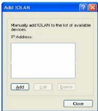
text_image
Add IOLAN Manually add IOLAN to the list of available devices. IP Address: Add Edit Delete CloseTo permanently add the IOLAN to the IOLAN list, click the Add button and type in the IPv4 or IPv6 address of the IOLAN. To permanently delete the IOLAN from the IOLAN list, select the IOLAN's IP address and click the Delete button.
Logging in to the IOLAN
To log in to the IOLAN, double-click on the IOLAN in the Device Server List. You will be prompted for the admin Password (the default is superuser).
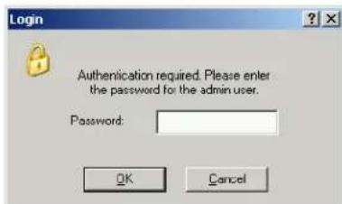
text_image
Login Authentication required. Please enter the password for the admin user. Password: OK CancelIf the authentication and connection are successful, the IOLAN's Server Info window is displayed. If you cannot connect to the IOLAN, you can highlight the IOLAN and click the Ping button to verify that the DeviceManager can communicate with the IOLAN's IP Address. If the ping times out, then you might need to set up a Gateway in your IOLAN or verify that your network is communicating correctly.
Using WebManager to Connect to the IOLAN
WebManager can connect to IOLANs that already have an assigned IP address or wirelessly to an IOLAN SDS W. See the WLAN section in this guide for configuration options for Client or Soft AP mode.
To connect to the IOLAN, type the IP address of the IOLAN into the Address field as such: http://10.10.234.34.
You will see the login screen.

text_image
perle Tracys-SDS2 Username: admin Password: Login Secure Login IOLAN SDS2 Version 3.3Logging into the IOLAN
Type in the admin password in the Password field and click the Login button. A user who does not have admin privileges can access EasyPort Web to access clustered serial ports, Perle Remote Power Switches (RPS), and/or RPS plugs (must already be configured on this IOLAN) by typing their user name and password on the login screen.
Configuration Files
Creating a New IOLAN Configuration in DeviceManager
In DeviceManager, when you select File, New, the New Configuration window is displayed.
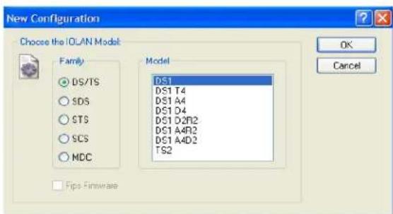
Select the IOLAN model for which you want to create a new configuration file. Any configuration file created in this manner can only be save locally. To download a created configuration file, you must first connect to the IOLAN, import the created configuration file into DeviceManager (this is not available in WebManager), and then download the configuration file to the IOLAN and reboot it. Opening an Existing Configuration File
If you select the File, Open, a browse window is opened so you can select the configuration file you want to edit. IOLAN configuration files saved in the DeviceManager can be in the IOLAN-native binary format (.dme) or as a text file (.txt), which can be edited with a text editor. Either configuration version can be imported into the DeviceManager. IOLAN configuration files saved from WebManager can also be opened into DeviceManager.
Importing an Existing Configuration File
If you have a local, saved configuration file that you want to download to the IOLAN, you must first connect to the IOLAN that you want to download the configuration file to. Once you have successfully logged into the IOLAN, in DeviceManager select Tools, Import Configuration from a File and in WebManager select Administration, Restore/Backup. You need to download the file in DeviceManager and in both managers you need to reboot the IOLAN.
Managing the IOLAN
Most of the management tasks, such as setting the time/date, downloading keys/certificates, downloading firmware, downloading custom files, resetting serial ports, etc., are found under the Tools menu option in the DeviceManager and under Administration in WebManager.

text_image
6Network Settings
Introduction
The Network section is used to configure the parameters that identify the IOLAN within the network and how the IOLAN accesses hosts on the network. The following configuration windows are available:
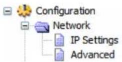
- IP Settings—This window configures the IOLAN's name, IP address, and Ethernet information. See Introduction for more information.
- Advanced—This window configures hosts that the IOLAN will be communicating with, routes, DNS/WINS servers, RIP, Dynamic DNS, and IPv6 Tunnels. IP Settings
IPv4 Settings
Overview
The parameters in IPv4 settings are used to access the IOLAN and how the IOLAN accesses the network.
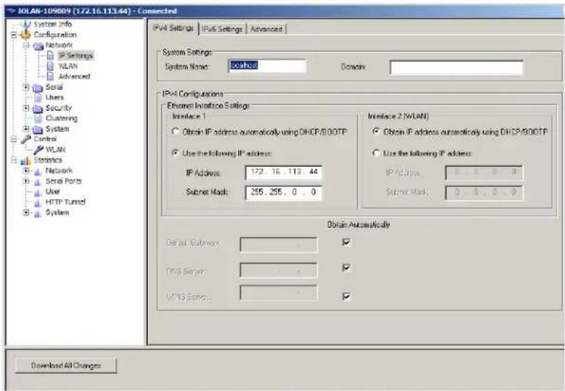
text_image
IOLAN-109809 (172.16.113.44) - Connected System Info Configuration Network IP Settings WLAN Advanced Serial Users Security Clustering System Control WLAN Statistics Network Serial Ports User HTTP Tunnel System IPv4 Settings | IPv6 Settings | Advanced | System Settings System Name: Local Domainy: IPv4 Configurations Ethernet Inversion Settings Interface 1 Obtain IP address automatically using DHCP/800TP Use the following IP address: IP Address: 172, 16, 113, 44 Submit Mask: 255, 255, 0, 0 Interface 2 (WLAN) Obtain IP address automatically using DHCP/800TP Use the following IP address: IP Address: 0, 0, 0, 0 Submit Mask: 0, 0, 0, 0 Obtain Automatically Default Gateway: DNS Server: WINS Server: Download All ChangesField Descriptions
Configure the following parameters:
| System Name | The System Name is used for informational purposes by such tools as the DeviceManager and is also used in conjunction with the Domain field to construct a fully qualified domain name (FQDN).Default: Terminal Server-xxxxxx (where xxxxxx is the last 6 digits of the Terminal Server's MAC address) |
| Domain | This field is combined with the System Name to construct the fully qualified domain name (FQDN). For example, if the domain is mycompany.com and the Server Name is set to accounting, the FQDN would be accounting.mycompany.com. |
| Obtain IP Address automatically using DHCP/BOOTP | When enabled, the IOLAN will request an IP address from the DHCP/BOOTP server. By default, when this option is enabled, the IOLAN will also attempt to retrieve the DNS server, WINS server, and default gateway from the DHCP/BOOTP server.Default: Disabled |
| Use the following IP Address | Assign a specific IP address to the IOLAN.Field Format: IPv4 address |
| IP Address | The IOLAN's unique IPv4 network Interface 1 IP address.Field Format: IPv4 address |
| Subnet Mask | The network subnet mask. For example, 255.255.0.0. |
| IP Address | The IOLAN's unique IPv4 network Interface 2 (WLAN) addressField Format: IPv4 address |
| Subnet Mask | The network subnet mask. For example, 255.255.0.0. |
| Default Gateway | Specify the gateway IP address that will provide general access beyond the local network.Field Format: IPv4 address |
| Default Gateway Obtain Automatically | When DHCP/BOOTP is enabled, you can enable this option to have the IOLAN receive the Default Gateway IP address from the DHCP/BOOTP server.Default: Enabled |
| DNS Server | Specify the IP address of a DNS host in your network for host name resolution.Field Format: IPv4 or IPv6 address |
| DNS Server Obtain Automatically | When DHCP/BOOTP is enabled, you can enable this option to have the IOLAN receive the DNS IP address from the DHCP/BOOTP server.Default: Enabled |
| WINS Server | Specify the IP address of a WINS (Windows Internet Naming Service) host in your network for host resolution.Field Format: IPv4 address |
| WINS Server Obtain Automatically | When DHCP/BOOTP is enabled, you can enable this option to have the IOLAN receive the WINS IP address from the DHCP/BOOTP server.Default: Enabled |
IPv6 Settings
Overview
Configure IPv6 settings when the IOLAN resides in an IPv6 network.
Field Descriptions
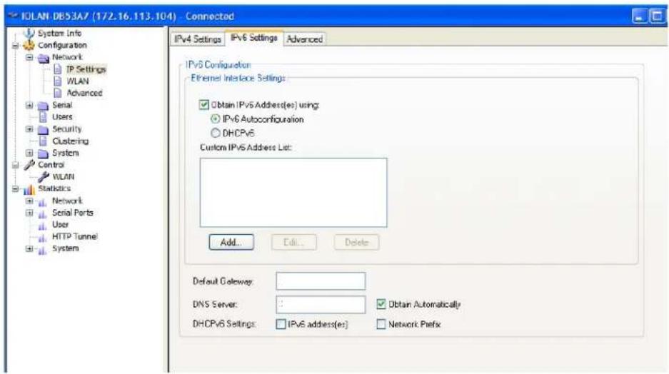
text_image
IOLAN DB53A7 (172.16.113.104) - Connected System Info Configuration Network IP Settings WLAN Advanced Serial Users Security Clustering System Control WLAN Statistics Network Serial Ports User HTTP Tunnel System IPv4 Settings IPv6 Settings Advanced IPv6 Configuration Ethernet Interface Settings: Obtain IPv6 Address(es) using: IPv6 Autoconfiguration DHCPv6 Custom IPv6 Address List: Add... Edit... Delete Default Gateway: DNS Server: : Obtain Automatically DHCPv6 Settings: IPv6 address(es) Network PrefixConfigure the appropriate parameters:
Obtain IPv6 When enabled, you can configure the IOLAN to obtain the IPv6 address(es) Address(es) using using IPv6 Autoconfiguration or a DHCPv6 server.
Default: Enabled
IPv6 Autoconfiguration When enabled, the IOLAN will send out a Router Solicitation message. If a Router Advertisement message is received, the IOLAN will configure the IPv6 address(es) and configuration parameters based on the information contained in the advertisement. If no Router Advertisement message is received, the IOLAN will attempt to connect to a DHCPv6 server to obtain IPv6 addresses and other configuration parameters.
Default: Enabled
DHCPv6 When enabled, requests IPv6 address(es) and configuration information from the DHCPv6 server.
Default: Disabled
Custom IPv6 Displays the list of custom configured IPv6 addresses.
Address List
Add Button Adds a custom IPv6 address.
Edit Button Edits an existing IPv6 address.
Delete Button Deletes an IPv6 address from the Custom IPv6 address list.
Default Gateway Specify the gateway IP address that will provide general access beyond the local network.
Field Format: IPv6 address
| DNS Server | Specify the IPv6 address of a DNS host in your network for host name resolution.Field Format:IPv6 address |
| DNS Server Obtain Automatically | When DHCPv6 is enabled, you can enable this option to have the IOLAN receive the DNS IP address from the DHCPv6 server.Default:Enabled |
| DHCPv6 Settings IPv6 Address(es) | When enabled, the IOLAN will accept IPv6 address(es) from the DHCPv6 server.Default:Disabled |
| DHCPv6 Settings Network Prefix | When enabled, the IOLAN will accept the network prefix from the DHCPv6 server.Default:Disabled |
Adding/Editing a Custom IPv6 Address
You can manually add one of the following:
- The IPv6 network prefix (and the IOLAN will determine an IPv6 address based on the network prefix and the IOLAN MAC address).
• The complete IPv6 address.
Configure the following parameters:
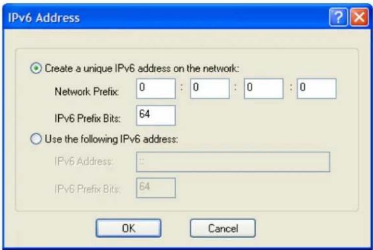
text_image
IPv6 Address Create a unique IPv6 address on the network: Network Prefix: 0 : 0 : 0 : 0 IPv6 Prefix Bits: 64 Use the following IPv6 address: IPv6 Address: : IPv6 Prefix Bits: 64 OK CancelCreate a unique When enabled, the IOLAN will derive an IPv6 address from the entered IPv6 address on the network prefix and the IOLAN's MAC address. network Default: Enabled
Network Prefix Specify the IPv6 network prefix. The IOLAN will derive the complete IPv6 address from the entered network prefix and the IOLAN's MAC address. Default: Enabled
Network Prefix Specify the network prefix bits for the IPv6 address. IPv6 Prefix Bits Range: 0-64 Default: 64
Use the following IPv6 address Enable this option when you want to enter a specific IPv6 address. Default: Disabled
IPv6 Address Specify the complete IPv6 address. Field Format: IPv6 address
IPv6 Address IPv6 Specify the network prefix bits for the IPv6 address. Prefix Bits Range: 0-128 Default: 64
Advanced
Overview
The Advanced tab configures DNS update, MTU size, IPv6 Advertising Router settings, and the Ethernet interface parameters.
Configure the parameters in the Advanced tab only if:
- you have already set up Dynamic DNS with DynDNS.com
- you want to specify the line speed and duplex for your Ethernet interface
- if you want the IOLAN to act as an IPv6 Advertising Router
Field Descriptions
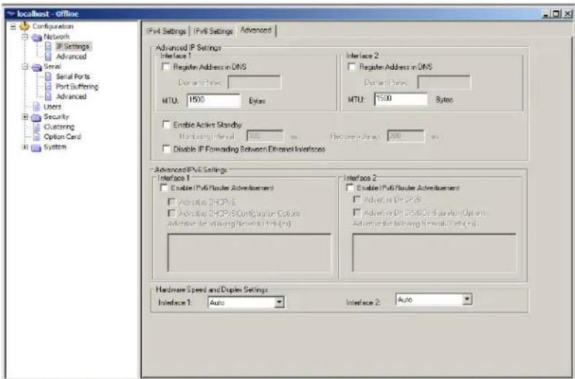
text_image
localHost - Offline Configuration Network IP Settings Advanced Serial Serial Ports Port Buffering Advanced Users Security Clustering Option Card System IPv4 Settings | IPv6 Settings | Advanced Advanced IP Settings Interface 1 Register Address in DNS Domain: Topic MTU: 1500 Bytes Interface 2 Register Address in DNS Domain: Topic MTU: 1500 Bytes Enable Active Standby Routing Interval: 1000 ms Figure: Page: 200 ms Disable IP Forwarding Between Ethernet Interfaces Advanced IPv6 Settings Interface 1 Enable IPv6 Router Advertisement Adaptive DHCP/E Adaptive DHCP/Configuration Options Adaptive DR Ordering (Reversal) (PSR ES) Interface 2 Enable IPv6 Router Advertisement Adaptive DR DP/SPS Adaptive DR DP/SPC Configuration Options Adaptive DR Ordering Interface (Reserved) Hardware Speed and Duplex Settings: Interface 1: Auto Interface 2: AutoConfigure the appropriate parameters:
Register Address in DNS When this parameter is set, the Terminal Server will provide the DHCP/DHCPv6 server with a fully qualified domain name (FQDN), so that the DHCP/DHCPv6 server can update the network's DNS server with the newly assigned IP address. Default: Disabled
| Maximum Transmission Unit (MTU) | The Maximum Transmission Unit (MTU) size of an IP frame that will be sent over the network. If your IOLAN has more then one interface each interface can be set separately, however only one MTU size can be set for both IPV4 or IPV6 frames.MTU IPV4: 68-1500 bytesMTU IPV6: 68-1500 bytes |
| Domain Prefix | (Dual Interface models only) A domain prefix to uniquely identify the interface to the DNS when the IOLAN has two Ethernet interfaces. The FQDN that is sent to the DNS will be one of the following formats, depending on what is configured in the System Settings section on the IPv4 Settings tab:. |
| Field Format: Maximum 8 alphanumeric characters | |
| Enable Active Standby | (SCS and SDS8/16/32C models with two Ethernet interfaces)Active Standby permits the grouping of Ethernet LAN connections to provide for link failover. Both Ethernet connections will have the same Ethernet MAC address. Active standby refers to the process by which a failure of one interface can be automatically overcome by having its traffic routed to the other interface.Default: Disabled |
| Disable IP Forwarding between Ethernet Interfaces | (SCS and SDS8/16/32C models with two Ethernet interfaces)When enabled, no IP traffic will be forwarded between Ethernet interfaces.Default: Disabled |
| Monitoring Interval | (SCS and SDS8/16/32C models with two Ethernet interfaces)The interval in which the active interface is checked to see if it is still communicating.Default: 100 ms |
| Recovery Delay (SCS and SDS8/16/32C models with two Ethernet interfaces)The time that the IOLAN will wait to make the secondary interface (Ethernet 2) active after it has been detected as up.Default: 200 ms | |
| Enable IPv6 Router Advertisement | When enabled, the IOLAN will periodically send IPV6 Router Advertisement messages and respond to Router Solicitation messages. The Router Advertisement message can be configured to contain any of the following information:DHICPv6—Use the DHCPv6 server to obtain additional IPV6 address(cs) and configuration parameters.DHICPv6 Configuration Options—Use DHCPv6 server to obtain additional configuration parameters.Network Prefixes—Advertise the selected custom configured network prefixes.Default: Disabled |
| Advertise DHCPv6 | When enabled, the Router Advertisement message indicates to use the DHCPv6 server for obtaining additional IPv6 addresses and configuration parameters.Default: Disabled |
| Advertise DHCPv6 Configuration Options | When enabled, the Router Advertisement message indicates to use the DHCPv6 server to obtain additional configuration parameters.Default: Disabled |
| Advertise the following Network Prefix(es) | The network prefix of the IPV6 addresses created in theIPv6 Settingstab in theCustom IPv6 Address Listare included in the Router Advertisement message. You can choose to enabled or disable specific network prefixes from being advertised to hosts.Default: Enabled |
| Interface 1 Hardware Speed and Duplex | Define the Ethernet connection speed (desktop models can support up to 100 Mbps and rack mount and medical unit models can support up to 1000 Mbps).Data Options:Auto—automatically detects the Ethernet interface speed and duplex10 Mbps Half Duplex10 Mbps Full Duplex100 Mbps Half Duplex100 Mbps Full Duplex1000 Mbps Full DuplexDefault: Auto |
| Interface 2 Hardware Speed and Duplex | Define the Ethernet connection speed (available on dual Ethernet models only).Data Options:Auto—automatically detects the Ethernet interface speed and duplex10 Mbps Half Duplex10 Mbps Full Duplex100 Mbps Half Duplex100 Mbps Full Duplex1000 Mbps Full DuplexDefault: Auto |
WLAN
Overview
The IOLAN can operate in two wireless modes.
- Client Mode
Soft-AP Mode
Client Mode
In Client mode the IOLAN can connect wirelessly to an Access Point (AP) wireless network. The IOLAN is preconfigure to run in Client mode. The IOLAN supports up to 8 client profiles for connecting to different Access Points (AP's).
IOLAN in Client Mode
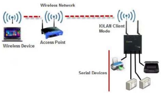
flowchart
graph TD
    A["Wireless Device"] --> B["Access Point"]
    B --> C["IOLAN Client Mode"]
    C --> D["Serial Devices"]
    D --> E["Server"]
    C --> F["Server"]
    style A fill:#f9f,stroke:#333
    style B fill:#bbf,stroke:#333
    style C fill:#dfd,stroke:#333
    style D fill:#dfd,stroke:#333
    style E fill:#dfd,stroke:#333
    style F fill:#dfd,stroke:#333
Soft-AP Mode
In Soft-AP Mode, the IOLAN acts as an Access Point for wireless clients. Up to 6 wireless clients can connect to the IOLAN.
IOLAN in Soft-AP Mode
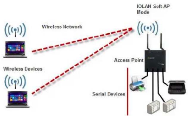
flowchart
graph TD
    A["Wireless Devices"] --> B["Wireless Network"]
    C["Wireless Devices"] --> B
    D["Serial Devices"] --> E["Access Point"]
    F["IOLAN Soft-AP Mode"] --> E
    E --> G["Server"]
    E --> H["Printer"]
    style A fill:#f9f,stroke:#333
    style C fill:#f9f,stroke:#333
    style D fill:#f9f,stroke:#333
    style F fill:#f9f,stroke:#333
    style E fill:#ccf,stroke:#333
Back to Back IOLANs
In Back to Back Mode, one IOLAN is configured in Soft-AP Mode (AP) and the second IOLAN is configured in Client Mode.
Back to Back IOLANs (one in Soft-AP Mode and the other in Client Mode)
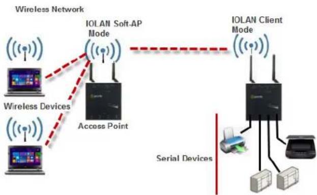
flowchart
graph TD
    A["Wireless Devices"] --> B["Access Point"]
    C["Wireless Network"] --> D["IOLAN Soft-AP Mode"]
    D --> E["Serial Devices"]
    E --> F["IOLAN Client Mode"]
    F --> G["Server"]
    F --> H["Printer"]
    style A fill:#f9f,stroke:#333
    style C fill:#f9f,stroke:#333
    style D fill:#ccf,stroke:#333
    style E fill:#cfc,stroke:#333
    style F fill:#fcc,stroke:#333
    style G fill:#cff,stroke:#333
    style H fill:#ffc,stroke:#333
Note: The WLAN network can be disabled
WLAN Global Settings
Selecting the WLAN tab will allow you to:
• set the WLAN parameters
- add/edit and delete profiles
- configure Soft-AP mode
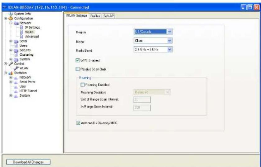
text_image
IOLAN-0853A7 (172.16.113.104) - Connected System Info Configuration Network IP Settings WLAN Advanced Serial Users Security Clustering System Control WLAN Statistics Networks Serial Ports User HTTP Tunnel System WLAN Settings Profiles Soft-AP Region US/Canada Mode Class Radio Band 2.4 GHz + 5 GHz wPS Enabled Passive Scan Only Roaming Roaming Enabled Roaming Decision Balanced Out of Range Scan Interval: 30 In Range Scan Interval: 300 Antenna Fix Diversity/MRC Download All ChangesRegion Select your wireless region.
Values: eu, japan, us-canada
Default: us-canada
Mode Specify the mode of operation for the IOLAN's WLAN operation.
Client: The IOLAN's wireless interface is used to connect to an AP (Access Point).
Soft-AP: The IOLAN's wireless interface acts as an AP (Access Point) allowing wireless clients to connect.
Disabled: The IOLAN's wireless capabilities are disabled. When disabled, the external WPS button will have no effect on the mode of the IOLAN.
Default: Client
Radio Band The IOLAN can operate over 2.4GHz or 5GHz. To support connections to one or the other bands use 2.4+5.
Values: 2.4, 5, 2.4+5
Default: 2.4+5 (dual-band)
WPS Enabled (in client mode) By default WPS (Wireless Protected Setup) mode is enabled to allow the IOLAN to easily connect to any routers/Access Points that are in supported WPS mode. In WPS mode, the IOLAN will scan (120 seconds) all networks to find the closest AP that is currently in WPS mode. The IOLAN will exchange credentials with that AP and then create an internal wireless profile (association) and will then exit WPS mode.
Values: on or off
Default: on
WPS Enabled (in Soft-AP mode) The WPS button can be used in Soft-AP mode to facilitate the connection of wireless clients.
Passive Scan Only In passive scan mode the IOLAN will scan all channels and listen for beacons being sent by the AP's on these channels. In active scan mode, the IOLAN actively seeks out AP's by sending out probes on these channels to accelerate their discovery. Active scan mode can be disabled by setting the Passive Scanning Only Mode to On.
Values: on or off
Default: off
Roaming Enabled This setting allows you to roam (reconnect) to a different wireless router/AP (with the same SSID) if there is a significant difference in the signal strength.
Values: on or off
Default: on
Roaming Decision When roaming, the IOLAN will be constantly scanning in the background to determine if there is a better AP to connect to within the ESSID network. Since this background scanning can have an effect on performance, it will normally do slow scans when the signal is strong and faster scans when the signal is weaker.
Values: Balanced, Optimize Bandwidth, Optimize Distance
Default: Balanced
Out of Range Scan Specify the out of range scan interval for fast roaming scans.
Values: 0-65535 seconds
Default: 30 seconds
In Range Scan Specify the in range scan interval for slow roaming scans.
Values: 0-65535 seconds
Default: 300 seconds
Antenna Rx Diversity/MRC
The IOLAN uses these techniques to optimize receive signals on it's wireless antennas. (4 port units only)
2.4-GHz supports MRC (Maximal-Ratio Combining)
5-GHz supports Diversity Capable
Default: on
WLAN Profiles
Overview
A WLAN profile defines all the settings necessary to establish a wireless connection with an Access Point. You can defined up to 8 client profiles on the IOALN. Associations with AP's in WPS mode will be automatically added by the IOLAN as a profile (priority 1).
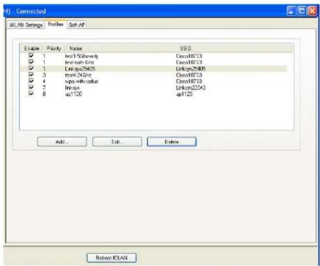
text_image
4) - Connected WLAN Settings Profes Soft AF Enable Priority Name SSID ✓ 1 test-15Gh-only Cisco18733 ✓ 1 test-bath GHz Cisco18733 ✓ 1 Linksys25405 Linksys25405 ✓ 3 test-424Ghz Cisco18733 ✓ 4 vsps with-tadius Cisco18733 ✓ 7 Linksys Linksys22043 ✓ 8 ap1120 ap1120 Add... Edit... Delete Reboot IOLANEnabled
Only enabled profiles will be considered for association with AP's
Values: off or on
Default: on
Add/Edit/Delete
Select button to add/delete or edit profiles.
Add/Edit/Delete
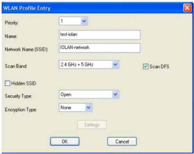
text_image
WLAN Profile Entry Priority: 1 Name: test-iolan Network Name (SSID): IOLAN-network Scan Band: 2.4 GHz + 5 GHz Scan DFS Hidden SSID Security Type: Open Encryption Type: None Settings OK Cancel| Priority | The connect priority order (1 being the highest) in which the IOLAN will attempt an association with AP's that match the SSID in the profile. If there are duplicate priority entries in the table, the IOLAN will connect to the duplicate entry with the most optimal AP based on signal strength and security type.Values: 1-8Default: 1 |
| Name | Enter the name for this profileValues: 1-32 characters, no spaces allowed |
| Network Name (SSID) | Specify an SSID (network name).Values: max of 32 characters (no spaces allow)Default: none or auto-created SSID |
| Radio Band | The IOLAN can operate over 2.4GHz or 5GHz. To support connections to one or the other bands use 2.4+5.Values: 2.4, 5, 2.4+5Default: 2.4+5 (dual-band) |
| Scan DFS Channel | The IOLAN supports DFS. When connected to an AP that is using Dynamic Frequency Selection, it will respond to the specific protocol requests. When scanning channels for AP's the IOLAN provides the option of skipping the DFS protected channels.Values: off or onDefault: on (applies to 5GHz mode only) |
| Hidden SSID | If this profile is defined to connect to an AP that has a hidden SSID then this option must be enabled. This will force the IOLAN to send a directed probe to this AP with the specified SSID in order to discover it and determine the channel that it is using.Values: off or onDefault: off |
Security/ Encryption
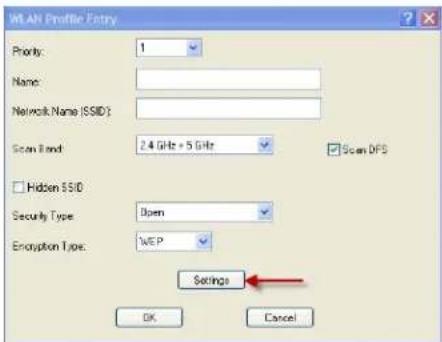
text_image
WLAN Profile Entry Priority: 1 Name: Network Name (SSID): Scan Band: 2.4 GHz + 5 GHz Scan DFS Hidden SSID Security Type: Open Encryption Type: WEP Settings OK Cancel| Authentication Protocol | CHAP | ● | ● | ● | ||||
| MSCHAP2 | ● | ● | ● | |||||
| EAP-MSCHAPV2 | ● | ● | ● | |||||
| MSCHAP2 | ● | ● | ● | |||||
| EAP-MSCHAPV2 | ● | ● | ● | |||||
| EAP-MD5 | ● | ● | ● | |||||
| EAP-GTC | ● | ● | ● | |||||
| EAP-MD5 | ● | ● | ● | |||||
| EAP-MD5 | ● | ● | ● | |||||
| Validate Sever Certificate | ● | ● | ● | |||||
| Roaming Identify | ● | ● | ● | |||||
| Security Type | Open | Shared | WPA-Personal | WPA2-Personal | WPA2-Enterprise | WPA-Enterprise | 802.1 | |
| Encryption Type | WEP | ● | ● | ● | ||||
| NONE | ● | |||||||
| AES | ● | ● | ● | ● | ||||
| TKIP | ● | ● | ● | ● | ||||
| Security Keys | ● | ● | ● | ● | ||||
| Authentication Method | EAP-TLS | ● | ● | ● | ||||
| PEAP | ● | ● | ● | |||||
| LEAP | ● | ● | ● | |||||
| EAP-TTLS | ● | ● | ● | |||||
| Username | ● | ● | ● | |||||
| Password | ● | ● | ● |
| Wepkey1 | Enter a wep key.Values: (5 or 13 characters) or (10 or 26 hexadecimal digits) |
| Wepkey2 | Enter a wep key.Values: (5 or 13 characters) or (10 or 26 hexadecimal digits) |
| Wepkey3 | Enter a wep key.Values: (5 or 13 characters) or (10 or 26 hexadecimal digits) |
| Wepkey4 | Enter a wep key.Values: (5 or 13 characters) or (10 or 26 hexadecimal digits) |
| Tx-key index | Select the TX key index to use. Values: 1-4 |
| Username | Specify a username to identify the IOLAN to the Radius server.Values: max of 254 charactersDefault: none |
| Password | Specify a password to identify the IOLAN to the Radius server.Values: max of 128 charactersDefault: none |
| Validate server certificate | Enable this option if you want the Radius server to validate that the IOLAN’s server’s certificate has been signed by a SSL/TLS certificate authority (CA). If you enable this option, you need to download an SSL/TLS certificate authority (CA) list file to the IOLAN.Values: yes or noDefault: no |
Soft-AP Mode
Overview
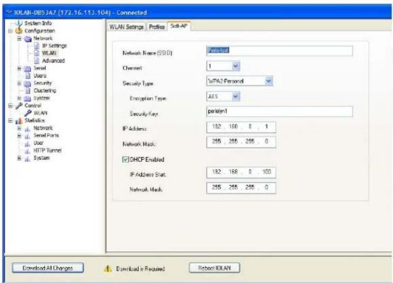
text_image
IOLAN-DB53A7 (172.16.113:104) - Connected System Info Configuration Network IP Settings WLAN Advanced Serial Users Security Clustering System Control WLAN Statistics Network Serial Ports User HTTP Tunnel System WLAN Settings Profiles Soft-AP Network Name (SSID) Channel 1 Security Type: WPA2 Personal Encryption Type: A65 Security Key: perkyn1 IP Address: 192 168 0 1 Network Mask: 255 255 255 0 DHCP Enabled IP Address Stat: 192 168 0 100 Network Mask: 255 255 255 0 Download All Changes Download is Required Reboot IOLANConfigure the appropriate parameters:
| SSID (network address) | Specify an SSID (network name).Values: max of 32 characters (no spaces allow)Default: none or auto-created SSID |
| Channel | Enter the channel number the IOLAN will use to connect to the AP.Values: (1-11) 2.4GHz (36,40,44,48) 5GHzDefault: Selecting a channel number between 1-11 will use 2.4GHz band and selecting channels 38, 40, 44 and 48 will use 5GHz band. |
| Security type | In Soft-AP Mode, the IOLAN supports wpa-personal and wpa2-personal encryption.wpa-personal: tkip, aesDefault: aeswpa2-personal: tkip, aesDefault: aes |
| Security Key | Specify a security key for this connection.Value: 64 hexadecimal digits or as a passphrase of 8-63 printable ascii characters |
| IP address | Enter an IPV4 address for the IOLAN on this WLAN.Default: 192.168.0.1 |
| Network mask | Enter the IOLAN’s subnet mask. For example 255.255.0.0 |
| Enable DHCP Server | This DHCP server can be used to give IP addresses to clients connecting on this wireless network.Value: off or onDefault: on |
| DHCP IP address | Enter the start IPV4 address of the DHCP pool.Value: IP addressDefault: 192.168.0.100 |
| DHCP subnet mask | Enter the IOLAN’s subnet mask. For example 255.255.0.0 |
Advanced
Host Table
Overview
The Host table contains the list of hosts that will be accessed by an IP address or Fully Qualified Domain Name (FQDN) from the IOLAN. This table will contain a symbolic name for the host as well as its IP address or FQDN. When a host entry is required elsewhere in the configuration, the symbolic name will be used.
Functionality
You can configure up to 50 hosts using IPv4 or IPv6 internet addresses on desktop IOLAN models; you can configure up to 100 hosts on rack mount and medical unit IOLAN models.
Field Descriptions
Configure the appropriate parameters:
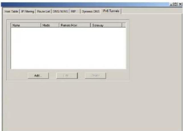
text_image
Host Table | IP Filtering | Route List | DNS/WINS | RIP | Dynamic DNS | IPv6 Tunnels | Name Mode Remo Host Gateway Add... Edit DenayAdd Button
Adds a host to the host table.
Edit Button
Changes a host that already exists in the host table.
Delete Button
Deletes a host from the host table
Adding/Editing a Host
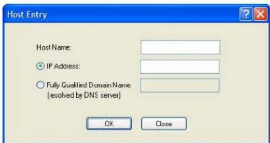
text_image
Host Entry Host Name: IP Address: Fully Qualified Domain Name: (resolved by DNS server) OK CloseConfigure the appropriate parameters:
Host Name The name of the host. This is used only for the IOLAN configuration.
Field Format: Up to 14 characters, no spaces.
IP Address The host's IP address.
Field Format: IPv4 or IPv6 address
Fully Qualified Domain Name When you have DNS defined in the IOLAN, you can enter a DNS resolvable fully qualified domain name (note: FQDN's are excluded as accessible hosts when IP Filtering is enabled).
Field Format: Maximum 254 alphanumeric characters
IP Filtering
Overview
The IP Filtering Host table allows you to configure:
• any host to connect to the IOLAN
• only hosts as defined in the Host Table and/or
• specify up to 6 IP address ranges
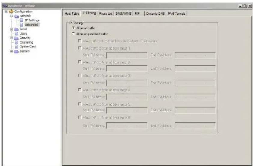
text_image
localhost - Offline Configuration Network IP Settings Advanced Serial Users Security Clustering Option Card System Host Table | IP Filtering | Route List | DNS/WINS | RIP | Dynamic DNS | IPv6 Tunnels | IP Filtering Allow all tables Allow only defined tables Allow effective port to port host defined with IP address: Allow traffic from address range 1. Start IP Address: End IP Address Allow traffic from address range 2. Start IP Address: End IP Address Allow traffic from address range 3. Start IP Address: End IP Address Allow traffic from address range 4. Start IP Address: End IP Address Allow traffic from address range 5. Start IP Address: End IP Address Allow traffic from address range 6. Start IP Address: End IP AddressFunctionality
You can specify up to 6 IP traffic to/from address ranges.
Field Descriptions
Configure the appropriate parameters
IP Filtering Data Options:
Allow all traffic - Allows any host to connect to the IOLAN.
Default: Allow all ranges
IP Filtering on Host Data Options:
Table
Allow only defined traffic to/from hosts defined with IP addresses - a security feature that when enabled, the IOLAN will only accept data from or send data to hosts configured in the IOLAN's Host Table.
IP Filtering on
Data Options:
Address Ranges
Allow traffic to/from address range - a security feature that when enabled, the IOLAN will only accept data from or send data to hosts configured within these IPv4 address ranges.
Route List
Overview
Entering routes in the routing list enables the identification of gateways to be used for accessing specific hosts or external networks from the IOLAN's local network.
Functionality
There are three types of routes:
- Default—A route that provides general access beyond your local network.
- Host—A route defined for accessing a specific host external to your local network.
• Network—A route defined for accessing a specific network external to your local network.
You can specify up to 20 routes on desktop IOLAN models; you can specify up to 49 routes on rack mount and medical unit IOLAN models.
Two types or gateways (method of accessing specific hosts or external networks) can be configured:
- Host—Specify a specify host that will provide access to the route destination.
- Interface—Specify the IPv6 tunnel, Remote Access (PPP)-defined serial port, or Remote Access (SLIP)-defined serial port that will provide access to the route destination.
Field Descriptions
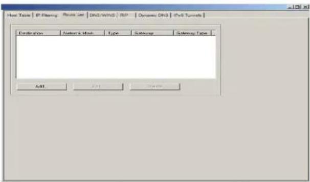
text_image
Host Table | IP Mapping | Tools List | DNS/WNSD | ISP | Dynamic DNS | IPv6 Tuning Origination Network Mask Type Sequence Sequence Type Add Add CancelThe following buttons are available on this window:
Add Button
Adds a route to the Route List.
Edit Button
Changes an existing route in the Route List.
Delete Button
Deletes a route from the Route List.
Adding/Editing Routes
From the Route List tab, if you click the Add or Edit button, you will be able to add a new or edit an existing route.
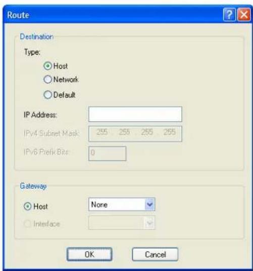
text_image
Route Destination Type: Host Network Default IP Address: IPv4 Subnet Mask 255 255 255 255 IPv6 Prefix Bits: 0 Gateway Host None Interface OK CancelConfigure the appropriate parameters:
Type Specify the type of route you want to configure.
Data Options:
- Host—A route defined for accessing a specific host external to your local network.
- Network—A route defined for accessing a specific network external to your local network.
- Default—A route which provides general access beyond your local network.
Default: Default
IP Address
When the route Type is defined as Host, this field will contain the IP address of the host. If the route Type is defined as Network, the network portion of the IP address must be specified and the Host port of the address will be set to 0. Example: to access network 10.10.20, the address 10.10.20.0 would be specified in this field.
Format: IPv4 or IPv6 address
IPv4 Subnet Mask
When the route is a Network route, you must specify the network's subnet mask.
IPv6 Prefix Bits
If the IP address is IPv6, then you must specify the network's prefix bits.
Range: 0-128
Host Select this option when a host is being used at the route gateway.
Default: Enabled, None
Interface
The Interface list is comprised of configured IPv6 tunnels and serial ports defined for Remote Access (PPP) and Remote Access (SLIP) profiles. Select this option when you want to use the specified interface as the gateway to the destination.
Field Option(s): IPv6 tunnels, Remote Access (PPP) and Remote Access (SLIP) serial ports
Default: Disabled
DNS/WINS
Overview
You can configure WINS servers for PPP-client name resolution and DNS servers for PPP-client name resolution and IOLAN host name resolution (for example, when specifying Bootup file).
Functionality
You can configure up to four DNS and four WINS servers. If you specified a DNS and/or WINS server on the Network, IP Settings tabs (either IPv4 or IPv6), it will be automatically entered into the appropriate list. If the DNS and/or WINS server is provided by a DHCP server, these will NOT be viewable in the list, however, you can add DNS and/or WINS servers to supplement the DHCP supplied server.
Field Descriptions
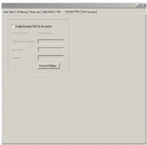
text_image
Host Table | IP Filling | Room List | DNS/WNT | RSP | Dynamic DNS | IP-S Tunnals | Enable Dynamic DNS for the system. Structure Provider: OPIONA-IP Registration Name: User Name: Password: Account SettingsThe following buttons are available on this window:
Add DNS Button Adds a DNS server.
Edit DNS Button Edits an existing DNS server.
Delete DNS Button Deletes a DNS server.
Add WINS Button Adds a WINS server.
Edit WINS Button Edits an existing WINS server.
Delete WINS Deletes a WINS server. Button
Editing/Adding DNS/WINS Servers
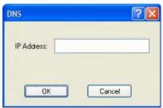
text_image
DNS IP Address: OK Cancel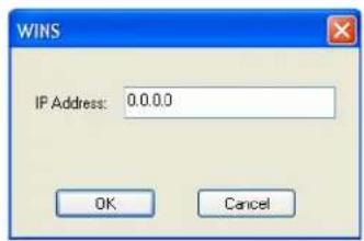
text_image
WINS IP Address: 0.0.0.0 OK CancelConfigure the parameter:
DNS IP Address
You can configure up to four DNS servers.
Field Format: IPv4 or IPv6 address
WINS IP Address
You can configure up to four WINS servers.
Field Format: IPv4 address
RIP
Overview
The Routing Information Protocol (RIP) is a routing protocol used with almost every TCP/IP implementation. Its function is to pass routing information from a router or gateway to a neighboring router(s) or gateway(s). RIP messages contain information about destinations which can be reached and the number of hops which are required. The hop-count is the basic metric of RIP and so RIP is referred to as a “distance vector protocol”. RIP messages are carried in UDP datagrams.
Functionality
You can configure RIP to selectively advertise networks remotely connected via a SLIP/PPP link on the Ethernet connection, and pass RIP routing information to remotely connected clients. As this can be undesirable in some environments, this behavior can be configured and is defaulted to the non-routing behavior.
Transmission and reception of Routing Information Protocol (RIP) packets over PPP and SLIP connections can be configured on a per user basis or on a per serial port basis.
The Routing parameter can be configured:
- On the Advanced tab for Remote Access (PPP) and Remote Access (SLIP) profiles configured for a serial port to determine the exchange of RIP packets between the IOLAN and remotely connected users connected from the serial side.
- On the Services tab for each local user to determine the exchange of RIP packets between the IOLAN and remotely connected users connected from the serial side.
- By the RADIUS server for users authenticated by RADIUS, the RADIUS-defined Framed-Routing parameter determines the exchange of RIP packets.
There are four options for setting the Routing parameters:
- None—Routing information is not exchanged across the link. This is the default setting for a line and a locally defined user.
- Send—Routing information is only transmitted to the remote user.
- Listen—Routing information is only received from the remote user.
- Send and Listen—Routing information is transmitted to and received from the remote user.
The local User Routing parameter or RADIUS Framed-Routing parameter, if set, override the serial port Routing parameter for a connection.
Field Descriptions
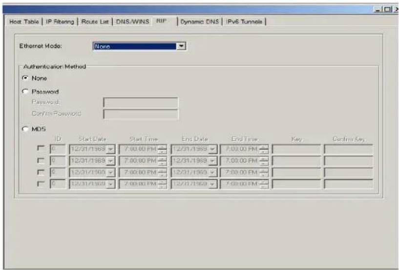
text_image
Host Table | IP Filtering | Route List | DNS/WINS | RIP | Dynamic DNS | IPv6 Tunnels | Ethernet Mode: None Authentication Method None Password Password: Confirm Password MDS ID Start Date Start Time End Date End Time_Key Cancel Key 0 12/31/1969 7:00:00 PM 12/31/1969 7:00:00 PM 0 12/31/1969 7:00:00 PM 12/31/1969 7:00:00 PM 0 12/31/1969 7:00:00 PM 12/31/1969 7:00:00 PM 0 12/31/1969 7:30:00 PM 12/31/1969 7:30:00 PM 0 12/31/1969 7:30:00 PM 12/31/1969 7:30:00 PMConfigure the appropriate parameters:
Ethernet Mode Enable/disable RIP (Routing Information Protocol) mode for the Ethernet interface.
Data Options:
• None—Disables RIP over the Ethernet interface.
- Send—Sends RIP over the Ethernet interface.
- Listen—Listens for RIP over the Ethernet interface.
- Send and Listen—Sends RIP and listens for RIP over the Ethernet interface.
Default: None
Authentication Specify the type of RIP authentication.
Method
Data Options:
• None—No authentication for RIP.
- Password—Simple RIP password authentication.
• MD5—Use MD5 RIP authentication.
Default: None
Password Specify the password that allows the router tables to be updated.
Confirm Password Retype in the password to verify that you typed in it correctly.
ID
The MD5 identification key.
Start Date The start date that the MD5 key becomes valid. The date format is dependent on your system's settings.
Start Time The time that the MD5 key becomes valid. The time format is dependent on your system's settings.
End Date
The last day that the MD5 key is valid. The date format is dependent on your system's settings.
End Time The time that the MD5 key becomes invalid. The time format is dependent on your system's settings.
Key The MD5 key that is being used by your routers.
Confirm Key
Retype the MD5 key that is being used by your routers to verify that it was typed correctly.
Dynamic DNS
Overview
Dynamic DNS Service providers enable users to access a server connected to the internet that has been assigned a dynamic IP address. The IOLAN product line has built-in support for the DynDNS.com service provider. Refer to www.DynDNS.com for information on setting up an account.
Functionality
When the IOLAN is assigned a dynamic IP address, it will inform the DynDNS.com service provider of its new IP address. Users can then use DynDNS.com as a DNS service to get the IP address of the IOLAN. In order to take advantage of this service, the following steps need to be taken.
- Create an account with DynDNS.com and configure the name your IOLAN will be known by on the internet (the Host name). For example, create a host name such as yourcompanySCS.DynDNS.org.
- Enable the Network Dynamic DNS feature and configure the IOLAN's dynamic DNS parameters to match the Host's configuration on the DynDNS.com server. Every time the IOLAN gets assigned a new IP address, it will update DynDNS.com with the new IP address.
- Users accessing the IOLAN via the internet can now access it via its fully qualified host name. For example, telnet yourcompanySCS.DynDNS.org.
Field Descriptions
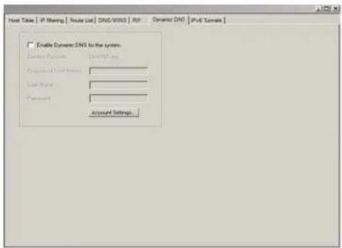
text_image
Enable Dynamic DOS to the system Drive Options: 10000000000000000000000000000000000000000000000000000000000000000000000000000000000000000000000000000 Load Method: Password: Account Settings...Configure the appropriate parameters:
Enable Dynamic DNS for the system
Enables/disables the dynamic DNS feature. When Dynamic DNS is enabled, the IOLAN will automatically update its IP address with DynDNS.org if it changes.
Default: Disabled
Host
Specify the registered hostname with DynDNS.org that will be updated with the IOLAN's IP address should it change. Put in the full name; for example, mydeviceserver.dyndns.org.
User Name Specify the user name used to access the account set up on the DynDNS.org server.
Password Specify the password used to access the account set up on the DynDNS.org server.
Account Settings Button Click this button to configure the Dynamic DNS DynDNS.org account information.
Account Settings
Enter the information about your DynDNS.com account so the IOLAN can communicate IP address updates. These settings are global and apply to all Dynamic DNS settings.
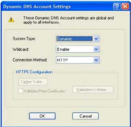
text_image
Dynamic DNS Account Settings System Type: Dynamic Wildcard: Enable Connection Method: HTTP HTTPS Configuration Cipher Suite Validate Peer Certificate Validation Criteria... OK CancelConfigure the appropriate parameters:
System Type Specify how your account IP address schema was set up with DynDNS.org. Refer to www.DynDNS.org for information about this parameter.
Data Options: Dynamic, Static, Custom
Default: Dynamic
Wildcard Adds an alias to *.yourcompanySCS.dyndns.org pointing to the same IP address as entered for yourcompanySCS.dyndns.org.
Connection Method Specify how the IOLAN is going to connect to the DynDNS.org server.
Data Options:
- HTTP
- HTTP through Port 8245
- HTTPS—for a secure connection to the DynDNS server
Default: Disabled
Cipher Suite Button Launches the cipher information window so you can specify the type of encryption that will be used for data that is transferred between the DynDNS.org server and the IOLAN.
See Cipher Suite Field Descriptions for more information.
Validate Peer Certificate
Enables/disables peer validation between the DynDNS.org server and the IOLAN. This may be desirable, since the DynDNS user name and password are sent from the Terminal Server to the DynDNS server when the IP address needs to be updated and when an account refresh is performed. Account refreshes are done periodically to ensure that DynDNS accounts do not auto-delete should the IP address change infrequently. This parameter will only take effect if HTTPS is selected as the connection method.
Default: Disabled
Validation Criteria Button
Launches the peer validation criteria window so you can specify the information used to validate the connection between the DynDNS.org server and the IOLAN.
See Validation Criteria Field Descriptions for more information.
Cipher Suite Field Descriptions
Some combinations of cipher groups may not be available on some firmware versions.
The SSL/TLS cipher suite is used to encrypt data between the IOLAN and the client. You can specify up to five cipher groups.
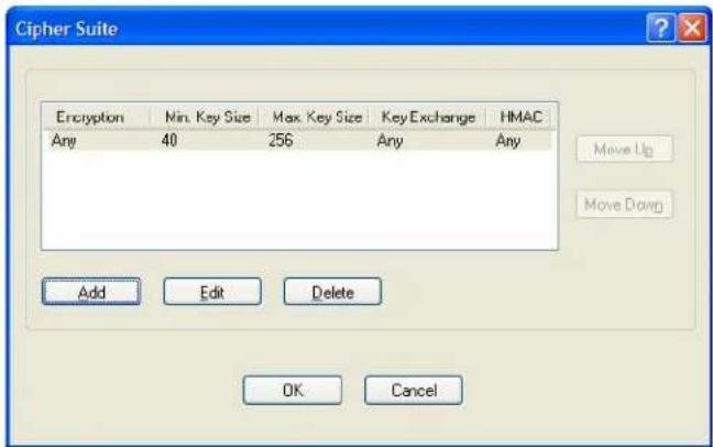
text_image
Cipher Suite Encryption Min. Key Size Max. Key Size Key Exchange HMAC Any 40 256 Any Any Move Up Move Down Add Edit Delete OK CancelThe following buttons are available:
Add Button Adds a cipher to the cipher list.
Edit Button Edits a cipher in the cipher list.
Delete Button Deletes a cipher from the cipher list.
Move Up Button Moves a cipher up in preference in the cipher list.
Move Down Button Moves a cipher down in preference in the cipher list.
Adding/Editing a Cipher Suite
To see a list of valid cipher suite combinations, see Appendix B, SSL/TLS Ciphers.
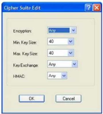
text_image
Cipher Suite Edit Encryption: Any Min. Key Size: 40 Max. Key Size: 40 Key Exchange: Any HMAC: Any OK CancelConfigure the following parameters:
| Encryption | Select the type of encryption that will be used for the SSL connection. Data Options: Any—Will use the first encryption format that can be negotiated. AES 3DES DES ARCFOUR ARCTWO AES-GCM Default:Any |
| Min Key Size | The minimum key size value that will be used for the specified encryption type. Data Options:40,56,64,128,168,256 Default:40 |
| Max Key Size | The maximum key size value that will be used for the specified encryption type. Data Options:40,56,64,128,168,256 Default:256 |
Key Exchange
The type of key to exchange for the encryption format.
Data Options:
- Any—Any key exchange that is valid is used (this does not, however, include ADH keys).
• RSA—This is an RSA key exchange using an RSA key and certificate. - EDH-RSA—This is an EDH key exchange using an RSA key and certificate.
- EDH-DSS—This is an EDH key exchange using a DSA key and certificate.
- ADH—This is an anonymous key exchange which does not require a private key or certificate. Choose this key if you do not want to authenticate the peer device, but you want the data encrypted on the SSL/TLS connection.
- ECDH-ECDSA—This is an ECDH key exchange using a ECDSA key and certificate.
Default: Any
HMAC
Select the key-hashing for message authentication method for your encryption type.
Data Options:
Any
MD5
SHA1
SHA256
SHA384
Default: Any
Validation Criteria Field Descriptions
If you choose to configure validation criteria, the information in the peer SSL/TLS certificate must match exactly the information configured in this window in order to pass peer authentication and create a valid SSL/TLS connection.

text_image
SSL Validation Criteria □ Country: □ State/Province: □ Locality: □ Organization: □ Organization Unit: □ Common Name: □ Email: OK CancelConfigure the following parameters:
Country
A country code; for example, US. This field is case sensitive in order to successfully match the information in the peer SSL/TLS certificate.
Data Options: Two characters
| State/Province | An entry for the state/province; for example, IL. This field is case sensitive in order to successfully match the information in the peer SSL/TLS certificate. Data Options: Maximum 128 characters |
| Locality | An entry for the location; for example, Chicago. This field is case sensitive in order to successfully match the information in the peer SSL/TLS certificate. Data Options: Maximum 128 characters |
| Organization | An entry for the organization; for example, Accounting. This field is case sensitive in order to successfully match the information in the peer SSL/TLS certificate. Data Options: Maximum 64 characters |
| Organization Unit | An entry for the unit in the organization; for example, Payroll. This field is case sensitive in order to successfully match the information in the peer SSL/TLS certificate. Data Options: Maximum 64 characters |
| Common Name An entry for common name; for example, the host name or fully qualified domain name. This field is case sensitive in order to successfully match the information in the peer SSL/TLS certificate. Data Options: Maximum 64 characters | |
| An entry for an email address; for example, acct@anycompany.com. This field is case sensitive in order to successfully match the information in the peer SSL/TLS certificate. Data Options: Maximum 64 characters |
IPv6 Tunnels
Overview
IPv6 tunnels transport IPv6 data packets from one IPv6 network to another IPv6 network over an IPv4 network. In addition to creating the IPv6 tunnel, you must also create the route that will transport the data packets through the IPv4 network in the Route List (see Route List for more information).
Field Descriptions
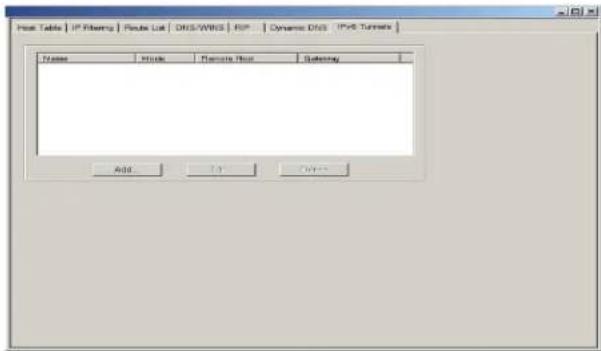
text_image
Host Table | IP Filtering | Route List | DNS/WBGS | RSP | Dynamic DNS | IPv6 Turrns Name Music Remote Floor Satency Add 12 FinishThe following buttons are available:
Add Button Adds an IPv6 tunnel.
Edit Button Edits an existing IPv6 tunnel.
Delete Button
Deletes an IPv6 tunnel. If a tunnel is associated with a route, it cannot be deleted until the route is either changed or deleted.
Adding/Editing an IPv6 Tunnel
When you add/edit an IPv6 tunnel, you are determining how an IPv6 message will reach an IPv6 device through an IPv4 network.
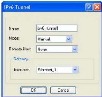
text_image
IPv6 Tunnel Name: pv6_tunnel1 Node: Manual Remote Host: None Gateway Interface: Ethernet_1 OK CancelConfigure the following parameters:
Name
The name of the IPv6 tunnel.
Field Format: Maximum 16 alphanumeric characters
Default: ipv6_tunnel1
Mode
The method or protocol that is used to create the IPv6 tunnel.
- Manual—When enabled, the IOLAN will manually create the IPv6 tunnel to the specified Remote Host through the specified Interface.
- 6to4—When enabled, the IOLAN will broadcast to the multicast address 192.88.99.1 through the specified Interface. When the closest 6to4 router responds, it will create the IPv6 tunnel, encapsulating and decapsulating IPv6 traffic sent to and from the IOLAN.
- Teredo—When enabled, the Teredo protocol encapsulates the IPv6 packet as an IPv4 UDP message, allowing it to pass through most network address translator (NAT) boxes and create an IPv6 tunnel to the specified Remote Host (a Teredo server) through the specified Interface.
Default: Manual
Remote Host
The IPv4 host that can access the IPv6 network when the Mode is Manual.
The Teredo server when the Mode is Teredo.
Default: None
Interface
The interface that the IOLAN is going to use to access the Remote Host. The list is comprised of the Ethernet interface(s) and serial ports configured for the Remote Access (PPP) or Remote Access (SLIP) profiles.
Default: Ethernet 1

natural_image
Yellow circular logo with a black number 7 and abstract star-like patterns inside (no text or symbols)Configuring Users
Introduction
You can configure up to four users in the IOLAN's local user database for all DS, SDS, and STS 1-port to 4-port desktop models, in addition to the admin user. You can configure up to 48 users in the IOLAN's local user database for all STS, SCS, and SDS rack mount models and all MDC medical unit models, in addition to the admin user. A user can even represent a device, like a barcode reader or a card swipe device, that you want to be authenticated.
When users are connecting to the IOLAN via serial ports, the user database can be used to:
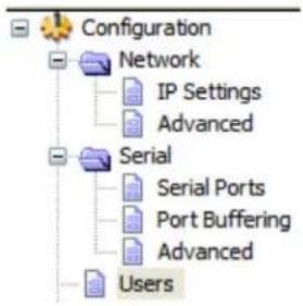
text_image
Configuration Network IP Settings Advanced Serial Serial Ports Port Buffering Advanced Users- Have the user authenticated prior to establishing a connection to a network host.
- Establish a different connection type to the host specific to each user.
• Create a profile different from the Default user profile.
When users are connecting to the IOLAN from a network connection, the user database can be used to:
- Provide authentication on the IOLAN prior to establishing a serial connection via PPP or SLIP.
- Authenticate users prior to providing access to a serially attached console port (such as a Unix server or router).
You do not need user accounts for users who are externally authenticated.
User Settings
Overview
The Users window allows you to add, edit, and delete users from the IOLAN.
Functionality
The Users window displays the users who have been configured. You can add users, edit existing users, or delete users from this window. You cannot delete the pre configured admin user. See Adding/Editing Users for information on the parameters available when adding or editing a user.
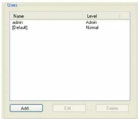
text_image
Users Name Level admin Admin [Default] Normal Add Edit DeleteAdding/Editing Users
General Tab
Overview
The General tab configures the basic user information.
Functionality
You must, minimally, provide a User Name and Level for a user.
Field Descriptions
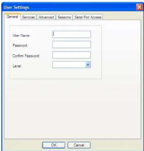
text_image
User Settings General Services Advanced Sessons Serial Port Access User Name: Password: Confirm Password: Level: OK CancelConfigure the following parameters:
User Name The name of the user.
Restrictions: Do not use spaces.
Password The password the user will need to enter to login to the IOLAN.
Confirm Password Enter the user's password again to verify it is entered correctly.
Level
The access that a user is allowed.
Data Options:
- Admin—The admin level user has total access to the IOLAN. You can create more than one admin user account but we recommend that you only have one. They can monitor and configure the IOLAN. Users configured with this level can access the unit either via serial Terminal Profile connection or via a network originated Telnet or SSH connection to the IOLAN.
- Normal—The Normal level user has limited access to the IOLAN. Limited CLI commands and Menu access are available with the ability to configure the user's own configuration settings. Users configured with this level can access the unit either via serial Terminal Profile connection or via a network originated Telnet or SSH connection to the IOLAN.
- Restricted—The Restricted level user can only access predefined sessions or access the Easy Port Access menu. Users configured with this level will be restricted to pre-defined sessions or limited CLI commands when connecting through the serial port via the Terminal Profile. The CLI commands are limited to those used for initiating a session. If connection to the IOLAN is done with Telnet or SSH from the network, the user will be presented with the Easy Port Access menu.
- Menu—The menu level user will only be able to access predefined session when connecting through a serial port with the Terminal profile or will be limited to the Easy Port Access menu when connecting from the network. The Easy Port Access allows the user to connect to the accessible line without disconnecting their initial connection to the IOLAN. Does not have any access to CLI commands.
When the admin user logs into the IOLAN, the prompt ends with a #, whereas all other users' prompts ends with a \$ or £, depending on the character set.
Default: Normal
A technique for giving a serially attach user (dial-in or terminal attached), the same menus as one that is network connected is to do the following:
- Define the serial port with a Terminal Profile using telnet protocol with a direct connection to Host IP address 127.0.0.0 (local loop back).
- When the user connects to that serial port a Telnet session will be established to the IOLAN and the user will appear to have connected from the network.
Services Tab
Overview
The Services tab configures the connection parameters for a user. Any connection parameters configured in this window will override the serial port connection parameters.
Functionality
When a Terminal profile is set for the serial port and Require Login has been selected, user's accessing the IOLAN through the serial port will be authenticated. Once authentication is successful, the Service specified here is started. For example, if the Service Telnet is specified, the IOLAN will start a Telnet connection to the specified Host IP/TCP Port after the user is successfully authenticated (logs in successfully).
Within the Terminal profile, there are a number of settings that apply to possible Services. Once it is known which user is connected, and which service is to be used, then the settings from both the Terminal profile and the user are used. User parameters take precedence over serial port parameters.
Field Descriptions
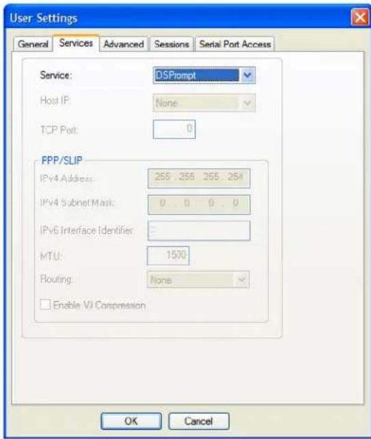
text_image
User Settings General Services Advanced Sessions Serial Port Access Service: DSPrompt Host IP: None TCP Port: 0 PPP/SLIP IPv4 Address: 255..255 255..254 IPv4 Subnet Mask: 0..0 0..0 IPv6 Interface Identifier: MTU: 1500 Routing: None Enable VJ Compression OK CancelConfigure the following parameters:
Service
Used in conjunction with the Terminal Profile. After the user has successfully been authenticated, the specified service is started.
Data Options: DSPrompt, Telnet, SSH, RLogin, SLIP, PPP, TCP Raw, SSL Raw
Default: DSPrompt
Host IP
When the User Service is set to Telnet or TCP Clear, the target host IP address. If no IP address is specified, the Host IP value in the Default User configuration will be used.
Default: None
TCP Port
When the User Service is Telnet, this is the target port number. The default value will change based on the type of Service selected; the most common known port numbers are used as the default values.
IPv4 Address
Used for User Service PPP or SLIP, sets the IP address of the remote user. Enter the address in dot decimal notation as follows:
- n.n.n.n—(where n is a number) Enter the IP address of your choice. This IP address will then be used in preference to the Remote IP Address set for a line.
The following IP addresses have a special meaning: - 255.255.255.254—The IOLAN will use the Remote IP Address set in the PPP settings for the serial port that this user is connecting to.
- 255.255.255.255—When the User Service is PPP, the IOLAN will allow the remote machine to specify its IP address (overriding the IP address negotiation value configured in the PPP settings).
- 255.255.255.255—When the User Service is SLIP, the IOLAN will use the Remote IP Address set for the line (no negotiation).
Default: 255.255.255.254
IPv4 Subnet Mask
If the remote user is on a subnet, enter the network's subnet mask. For example, a subnet mask of 255.255.0.0.
IPv6 Interface Indentifier
Used for User Service PPP, sets the IPv6 address of the remote user. Enter the address in IPv6 format.
Field Format: The first 64 bits of the Interface Identifier must be zero, therefore, ::abcd:abcd:abcd:abcd is the expected format.
MTU
Used for User Service PPP or SLIP, specifies the maximum size of packets, in bytes, being transferred across the link. On noisy links it might be preferable to fragment large packets being transferred over the link, since there will a be quicker recovery from errors.
Data Options:
- PPP—MTU will be the maximum size of packets that the IOLAN will negotiate for this port. This value is negotiated between the two ends of the link.
- SLIP—MTU will be the maximum size of packets being sent by the IOLAN.
The User MTU value will override the MTU/MRU values set for a Serial Port.
Range: PPP: 64-1500 bytes, SLIP: 256-1006 bytes
Default: PPP is 1500 bytes, SLIP is 256 bytes
Routing
Determines the routing mode used for RIP packets on the PPP and SLIP interfaces. Values are:
- None—RIP packets are neither received nor sent by the IOLAN.
- Send—RIP packets can only be sent by the IOLAN.
- Listen—RIP packets can only be received by the IOLAN.
- Send and Listen—RIP packets are sent and received by the IOLAN.
Default: None
Enable VJ Compression
Used for User Service PPP or SLIP, determines whether Van Jacobsen Compression is used on the link. VJ compression is a means of reducing the standard TCP/IP header from 40 octets to approximately 5 octets. This gives a significant performance improvement, particularly when interactive applications are being used. For example, when the user is typing, a single character can be transmitted and thus have the overhead of the full TCP/IP header. VJ Compression has minimal effect on other types of links, such as ftp, where the packets are much larger. The User VJ Compression option will override the VJ Compression value set for a Serial Port.
Default: Disabled
Advanced Tab
Overview
The Advanced tab is used to configure those parameters that control the user session; this includes session length, language, the hotkey used for switching between sessions, access to clustered ports, etc.
Field Descriptions
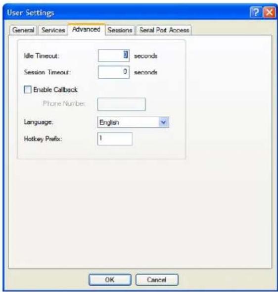
text_image
User Settings General Services Advanced Sessions Serial Port Access Idle Timeout: 0 seconds Session Timeout: 0 seconds Enable Callback Phone Number: Language: English Hotkey Prefix: 1 OK CancelConfigure the following parameters:
Idle Timeout
The amount of time, in seconds, before the IOLAN closes a connection due to inactivity. The default value is 0 (zero), meaning that the Idle Timer will not expire (the connection is open permanently). The User Idle Timeout will override all other Serial Port Idle Timeout parameters.
Range: 0-4294967
Default: 0
| Session Timeout | The amount of time, in seconds, before the IOLAN forcibly closes a user's session (connection). The default value is 0 (zero), meaning that the session timer will not expire (the session is open permanently, or until the user logs out). The User Session Timeout will override all other Serial Port Session Timeout parameters. Range: 0-4294967 Default: 0 |
| Enable Callback | When enabled, enter a phone number for the IOLAN to call the user back (the Enable Callback parameter is unrelated to the Serial Port Remote Access (PPP) profile Dial parameter). Note: the IOLAN will allow callback only when a user is authenticated. If the protocol over the link does not provide authentication, there will be no callback. Therefore, when the Serial Port profile is set to Remote Access (PPP), you must use either PAP or CHAP, because these protocols provide authentication. The IOLAN supports another type of callback, Roaming Callback, which is configurable when the Serial Port profile is set to Remote Access (PPP). Default: Disabled |
| Phone Number | The phone number the IOLAN will dial to callback the user (you must have se Enable Callback enabled). Restrictions: Enter the number without spaces. |
| Language | You can specify whether a user will use English or Custom Language as the language that appears in the Menu or CLI. The IOLAN supports one custom language that must be downloaded to the IOLAN. Default: English See Language Support for more information about Custom Languages. |
| Hotkey Prefix | The prefix that a user types to control the current session. Data Options: ^a number-To switch from one session to another, press ^a (Ctrl-a) and then the required session number. For example, ^a 2 would switch you to session 2. Pressing ^a 0 will return you to the IOLAN Menu. ^a n-Display the next session. The current session will remain active. The lowest numbered active session will be displayed. ^a p-Display the previous session. The current session will remain active. The highest numbered active session will be displayed. ^a m-To exit a session and return to the IOLAN. You will be returned to the menu. The session will be left running. ^a l-(Lowercase L) Locks the serial port until the user unlocks it. The user is prompted for a password (any password, excluding spaces) and the serial port is locked. The user must retype the password to unlock the serial port. ^r-When you switch from a session back to the Menu, the screen may not be redrawn correctly. If this happens, use this command to redraw it properly. This is always Ctrl R, regardless of the Hotkey Prefix. The User Hotkey Prefix value overrides the Serial Port Hotkey Prefix value. You can use the Hotkey Prefix keys to lock a serial port only when the serial port's Allow Port Locking parameter is enabled. Default: Hex 01 (Ctrl-a or ^a) |
Sessions Tab
Overview
The Sessions tab is used to configure specific connections for users who are accessing the network through the IOLAN's serial port.
Functionality
Users who have successfully logged into the IOLAN (User Service set to DSprompt) can start up to four login sessions on network hosts. These users start sessions through the EasyPort Menu option Sessions.
Multiple sessions can be run simultaneously to the same host or to different hosts. Users can switch between different sessions and also between sessions and the IOLAN using Hotkey commands (see Hotkey Prefix for a list of commands).
Users with Admin or Normal privileges can define new sessions and use them to connect to Network hosts; they can even configure them to start automatically on login to the IOLAN. Restricted and Menu users can only start sessions predefined for them in their user configuration.
Field Descriptions
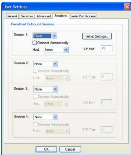
text_image
User Settings General Services Advanced Sessions Serial Port Access Predefined Outbound Sessions Session 1: Telnet Connect Automatically Host: None Telnet Settings... TCP Port: 23 Session 2: None Connect Automatically Host: None TCP Port: 0 Session 3: None Connect Automatically Host: None TCP Port: 0 Session 4: None Connect Automatically Host: None TCP Port: 0 OK CancelConfigure the following parameters:
| Session 1, 2, 3, 4 | You can configure up to four (4) sessions that the user can select from to connect to a specific host after that user has successfully logged into the IOLAN (used only on serial ports configured for theTerminalprofile).Data Options:None—No connection is configured for this session.Telnet—For information on the Telnet connection window, seeTelnet Settings.SSH—For information on the SSH connection window, seeSSH Settings.RLogin—For information on the RLogin connection window, seeRlogin Settings.Default: None |
| Settings Button | Click this button to configure the connection parameters for this session. |
| Connect Automatically | Specify whether or not the session(s) will start automatically when the user logs into the IOLAN.Default: Disabled |
| Host | The host that the user will connect to in this predefined session.Default: None |
| TCP Port | The TCP port that the IOLAN will use to connect to the host in this predefined session.Default: Telnet-23, SSH-22, Rlogin-513 |
Serial Port Access Tab
Overview
The Serial Port Access tab controls the user's read/write access on any given IOLAN serial port. This pertains to users that are connecting from the network to a serial over a Console Management type session.
This can be useful when you have multiple users connecting to the same serial device and you wish to control the viewing and/or the write to and from the device. See the Multisessions and User Authentication parameters in the Console Management Profile for the serial port settings.
Field Descriptions
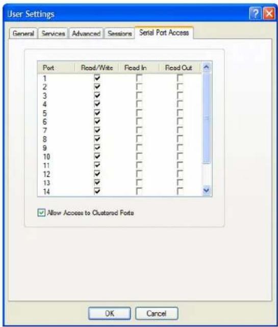
text_image
User Settings General Services Advanced Sessions Serial Port Access Port Read/Write Fixed In Fixed Out 1 ✓ □ □ □ 2 ✓ □ □ □ 3 ✓ □ □ □ 4 ✓ □ □ □ 5 ✓ □ □ □ 6 ✓ □ □ □ 7 ✓ □ □ □ 8 ✓ □ □ □ 9 ✓ □ □ □ 10 ✓ □ □ □ 11 ✓ □ □ □ 12 ✓ □ □ □ 13 ✓ □ □ □ 14 ✓ □ □ □ Allow Access to Clustered Ports OK CancelConfigure the following parameters:
Serial Port Access
Specifies the user access rights to each IOLAN serial port device. There can be multiple users connected to a particular serial device and these settings determine the rights of this user for any of the listed serial ports.
Data Options:
- Read/Write—The user has read and write access to the serial port.
- Read In—The User will see data going to the serial port, from all network-connected users that have write privileges to this serial port.
- Read Out—The user will have access to all data originating from the serial device.
Users can read data going in both directions by selecting both the Read In and Read Out options.
Default: Read/Write
Allow Access to Clustered Ports
When enabled, allows the user access to IOLANs that have been configured in the clustering group.
Default: Enabled

text_image
8Configuring Security
Introduction
The Security group includes the following configuration options:
- Authentication—When a serial port is configured for the Console Management or TCP Sockets profile, the user can be authenticated either locally in the IOLAN user profile or externally. This option configures the external authentication server. See Authentication for more information.
- SSH—This configuration window configures the SSH server in the IOLAN. See SSH for more information.
- SSL/TLS—This configuration window configures global SSL/TLS settings, which can be overridden on the serial port level. See SSL/TLS for more information.
- VPN—This configuration window configures the Virtual Personal Network (VPN) IPsec and L2TP/IPsec tunnel parameters. See VPN for more information.
- HTTP Tunnel—This configuration window configures the Http Tunneling parameters. See HTTP Tunneling for more information.
- Services—This configuration window is used to enable/disabled client and daemon services that run in the IOLAN. See Services for more information.
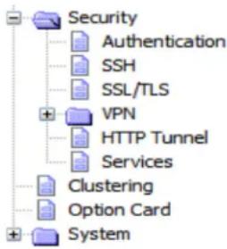
text_image
Security Authentication SSH SSL/TLS VPN HTTP Tunnel Services Clustering Option Card SystemAuthentication
Authentication can be handled by the IOLAN or through an external authentication server.
Authentication is different from authorization, which can restrict a user's access to the network (although this can be done through the concept of creating sessions for a user, see Sessions Tab for more information). Authentication ensures that the user is defined within the authentication database—with the exception of using the Guest authentication option under Local Authentication, which can accept any user ID as long as the user knows the configured password.
For external authentication, the IOLAN supports RADIUS, Kerberos, LDAP/Microsoft Active Directory, TACACS+, SecurID, and NIS. You can specify a primary authentication method and a secondary authentication method. If the primary authentication method fails (cannot connect to the server or authentication fails), the secondary authentication method is tried (unless you enable the Only Use as backup option, in which case the secondary authentication method will be tried only when the IOLAN cannot communicate with the primary authentication host). This allows you to specify two different authentication methods. If you do specify two different authentication methods, the user will be prompted for his/her username once, but will be prompted for a password for each authentication method tried. For example, user Alfred's user ID is maintained in the secondary authentication database, therefore, he will be prompted for his password twice, because he is not in the primary authentication database. Unlike the other external authentication methods, RADIUS and TACACS+ can also send back Serial Port and User parameters that are used for the duration of the
connection. Therefore, any parameters configured by RADIUS or TACACS+ will override the same parameters configured in the IOLAN. See Appendix A, RADIUS and TACACS+ for more information.
Authentication
In the Authentication window, you can select up to two methods of authentication made up of external authentication options and/or the local user database.
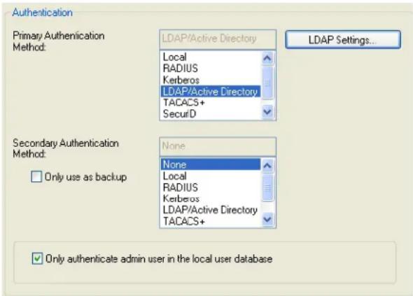
text_image
Authentication Primary Authentication Method: LDAP/Active Directory Local RADIUS Kerberos LDAP/Active Directory TACACS+ SecurD LDAP Settings... Secondary Authentication Method: None None Local RADIUS Kerberos LDAP/Active Directory TACACS+ Only use as backup Only authenticate admin user in the local user databaseConfigure the following parameters:
| Primary Authentication Method | The first authentication method that the IOLAN attempts. Data Options: Local, RADIUS, Kerberos, LDAP/Microsoft Active directory, TACACS+, SecurID, NIS Default: Local |
| Secondary Authentication Method | If the Primary Authentication Method fails, the next authentication method that the IOLAN attempts. You can choose to use authentication methods in combination. For example, you can specify the Primary Authentication Method as Local and the Secondary Authentication Method as RADIUS. Therefore, some users can be defined in the IOLAN (Local) others in RADIUS. Data Options: None, Local, RADIUS, Kerberos, LDAP/Microsoft Active Directory, TACACS+, SecurID, NIS Default: None |
| Settings Button | Click this button to configure the authentication method. |
| Only use as backup | The secondary authentication method will be tried only when the IOLAN cannot communicate with the primary authentication host. Default: Disabled |
| Only authenticate admin user in the local database | When enabled, the IOLAN will only authenticate the admin user in the local user database, regardless of any external authentication methods configured. When disabled, a user called admin must exist when only external authentication methods are configured, or you will not be able to access the IOLAN as the admin user, except through the console port. Default: Enabled |
Local
Overview
When Local authentication is selected, the user must either be configured in the IOLAN's User List or you must enable Guest users.
Field Descriptions
Configure the following parameters:
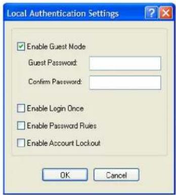
text_image
Local Authentication Settings Enable Guest Node Guest Password: Confirm Password: Enable Login Once Enable Password Rules Enable Account Lockout OK CancelEnable Guest Mode Allow users who are not defined in the Users database to log into the IOLAN with any user ID and the specified password. Guest users inherit their settings from the Default User's configuration.
Default: Disabled
Guest Password The password that Guest users must use to log into the IOLAN.
Confirm Password Type the Guest Password in again to verify that it is correct.
Enable Login Once When this option is selected, only one user with the same username can be signed in at one time. Should the same user with the same username attempt to sign in again, their first session will be terminated and they will gain entry to their new session.
Enable Password Rules When this option is selected, the following password rules will apply. The password must be 8 characters long and contain at least one number.
Enable Account Lockout When this option is selected, the IOLAN's internal local user database will provide a 10 second delay after each invalid attempt. If 5 invalid attempts are made within 1 minute the user will be locked out from further attempts for 5 minutes.
RADIUS
Overview
RADIUS is an authentication method that the IOLAN supports that can send back User information; see RADIUS for more information on the User parameters that can be sent back by RADIUS.
General Field Descriptions
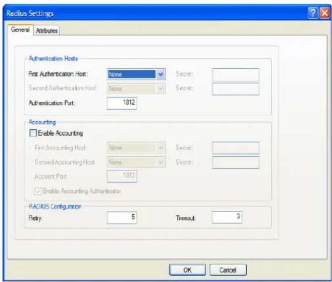
text_image
Radius Settings General Attributes Authentication Hosts First Authentication Host: None Secret: Second Authentication Host: None Secret: Authentication Port: 1812 Accounting Enable Accounting First Accounting Host: None Secret: Second Accounting Host: None Secret: Account Port: 1813 Enable Accounting Authenticator RADIUS Configuration Fltery: 5 Timeout: 3 OK CancelConfigure the following parameters:
First Authentication Name of the primary RADIUS authentication host. Host Default: None
Second Name of the secondary RADIUS authentication host, should the first RADIUS Authentication Host host fail to respond. Default: None
Secret The secret (password) shared between the IOLAN and the RADIUS authentication host.
Authentication Port The port that the RADIUS host listens to for authentication requests. Default: 1812
Enable Accounting Enables/disables RADIUS accounting. Default: Disabled
First Accounting Host Name of the primary RADIUS accounting host. Default: None
Second Accounting Name of the secondary RADIUS accounting host. Host Default: None
Secret The secret (password) shared between the IOLAN and the RADIUS accounting host.
Account Port The port that the RADIUS host listens to for accounting requests.
Default: 1813
Enable Accounting Authenticator Enables/disables whether or not the IOLAN validates the RADIUS accounting response.
Default: Enabled
Retry The number of times the IOLAN tries to connect to the RADIUS server before erroring out.
Range: 0-255
Default: 5
Timeout The time, in seconds, that the IOLAN waits to receive a reply after sending out a request to a RADIUS accounting or authentication host. If no reply is received before the timeout period expires, the IOLAN will retry the same host up to and including the number of retry attempts.
Range: 1-255
Default: 3 seconds
Attributes Field Descriptions
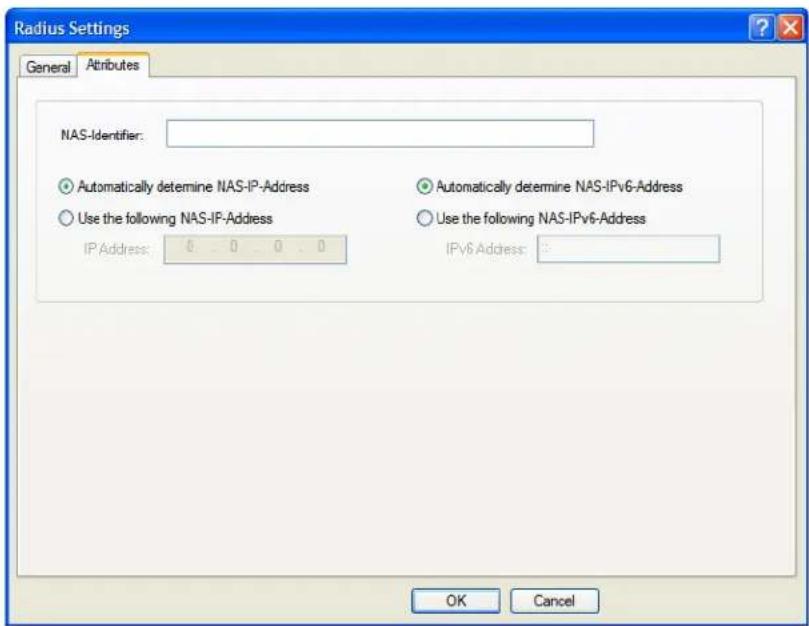
text_image
Radius Settings General Attributes NAS-Identifier: Automatically determine NAS-IP-Address Use the following NAS-IP-Address IP.Address: 0 0 0 0 Automatically determine NAS-IPv6-Address Use the following NAS-IPv6-Address IPv6 Address: 0 OK CancelConfigure the following parameters:
NAS-Identifier This is the string that identifies the Network Address Server (NAS) that is originating the Access-Request to authenticate a user.
Field Format: Maximum 31 characters, including spaces
Automatically determine NAS-IP-When enabled, the IOLAN will send the IOLAN's Ethernet 1 IPv4 address to the RADIUS server.
Address Default: Enabled
| Use the following NAS-IP-Address | When enabled, the IOLAN will send the specified IPv4 address to the RADIUS server.Default: Disabled |
| IP Address | The IPv4 address that the IOLAN will send to the RADIUS server.Default: 0.0.0.0 |
| Automatically determine NAS-IPv6-Address | When enabled, the IOLAN will send the IOLAN’s IPv6 address to the RADIUS server.Default: Enabled |
| Use the following NAS-IPv6-Address | When enabled, the IOLAN will send the specified IPv6 address to the RADIUS server.Default: Disabled |
| IPv6 Address | The IPv6 address that the IOLAN will send to the RADIUS server.Field Format: IPv6 address |
Kerberos
Field Descriptions
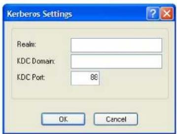
text_image
Kerberos Settings Realm: KDC Domain: KDC Port: 88 OK CancelConfigure the following parameters:
Realm The Kerberos realm is the Kerberos host domain name, in upper-case letters.
KDC Domain The name of a host running the KDC (Key Distribution Center) for the specified realm. The host name that you specify must either be defined in the IOLAN's Host Table before the last reboot or be resolved by DNS.
KDC Port The port that the Kerberos server listens to for authentication requests.
Default: 88
LDAP/Microsoft Active Directory
Overview
LDAP (Lightweight Directory Access Protocol) is an application protocol for querying and modifying directory services running over TCP/IP. It is also used as a method of authenticating users. Microsoft Active Directory is an LDAP like directory service. It can be used for authenticating users in a similar fashion to LDAP. In this manual, the use of LDAP is synonymous with Microsoft Active Directory.
The following parameter need to be configured to use this feature.
Field Descriptions
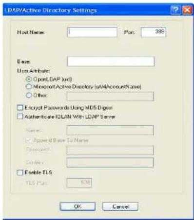
text_image
LDAP/Active Directory Settings Host Name: 1 Port: 388 Eases: User Attribute: ○ OpenLDAP (uc) ○ Microsoft Active Directory (SAMAccountName) ○ Other: □ Encrypt Passwords Using MDS Digest □ Authenticate IQLIN With LDAP Server Name: □ Append Base To Name Password: Binary: □ Enable TLS TLS Plus: 638 OK CancelHost Name The name or IP address of the LDAP/Microsoft Active Directory host. If you use a host name, that host must either have been defined in the IOLAN's Host Table before the last reboot or be resolved by DNS. If you are using TLS, you must enter the same string you used to create the LDAP certificate that resides on your LDAP/Microsoft Active Directory server.
Port The port that the LDAP/Microsoft Active Directory host listens to for authentication requests.
Default: 389
Base The domain component (dc) that is the starting point for the search for user authentication. You can enter up to 128 characters for the base.
User Attribute
This defines the name of the attribute used to communicate the user name to the server.
Options:
- OpenLDAP(uid)—Chose this option if you are using an OpenLDAP server. The user attribute on this server is “uid”.
- Microsoft Active Directory(sAMAccountName)—Chose this option if your LDAP server is a Microsoft Active Directory server. The user attribute on this server is “sAMAccountName”.
- Other—If you are running something other than a OpenLDAP or Microsoft Active Directory server, you will have to find out from your system administrator what the user attribute is and enter it in this field.
Default: OpenLDAP(uid)
Encrypt Passwords Using MD5 digest
Checking this parameter will cause the IOLAN to encrypt the password using MD5 digest before sending it to server. If this option is not checked, the password is sent to the server in the clear.
Default: Disabled
Authenticate IOLAN with LDAP server
This option will cause the Terminal Server to authenticate with the LDAP server before the user authentication takes place. The user name/password to use for this authentication is configured below.
Default: Disabled
Name The user name associated with the IOLAN
Append Base to Name
When checked, this causes the domain component configured in the “base” parameter to be appended to the user name. This allows for a fully qualified name to be used when authenticating the IOLAN.
Default: Enabled but if the base parameter is not configured, it does not modify the name.
Confirm
You must enter the exact same value as the password field. Since the password is not echoed, this ensures that the field was entered correctly.
Default: Blank
Enable TLS
Enables/disables the Transport Layer Security (TLS) with the LDAP/Microsoft Active Directory host.
Default: Disabled.
TLS Port
Specify the port number that LDAP/Microsoft Active Directory will use for TLS.
Default: 636
If you are using LDAP or Microsoft Active Directory with TLS, you need to download a CA list to the IOLAN that includes the certificate authority (CA) that signed the LDAP certificate on the LDAP host by selecting Tools, Advanced, Keys and Certificates. See Keys and Certificates for more information on the LDAP certificate.
TACACS+
Overview
TACACS+ is an authentication method that the IOLAN supports that can send back User information; see Appendix A, RADIUS and TACACS+ for more information on the User parameters that can be sent back by TACACS+.
Field Descriptions
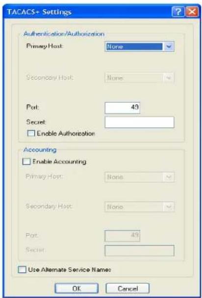
text_image
TACACS+ Settings Authentication/Authorization Primary Host: None Secondary Host: None Port: 49 Secret: Enable Authorization Accounting Enable Accounting Primary Host: None Secondary Host: None Port: 49 Secret: Use Alternate Service Names: OK CancelConfigure the following parameters:
| Authentication/ Authorization Primary Host | The primary TACACS+ host that is used for authentication. Default: None |
| Authentication/ Authorization Secondary Host | The secondary TACACS+ host that is used for authentication, should the primary TACACS+ host fail to respond. Default: None |
| Authentication/ Authorization Port | The port number that TACACS+ listens to for authentication requests. Default: 49 |
| Authentication/ Authorization Secret | The TACACS+ shared secret is used to encrypt/decrypt TACACS+ packets in communications between two devices. The shared secret may be any alphanumeric string. Each shared secret must be configured on both client and server sides. |
| Enable Authorization | Enables authorization on the TACACS+ host, meaning that IOLAN-specific parameters set in the TACACS+ configuration file can be passed to the IOLAN after authentication. Default: Disabled |
Enable Accounting Enables/disables TACACS+ accounting.
Default: Disabled
| Accounting Primary Host | The primary TACACS+ host that is used for accounting.Default: None |
| Accounting Secondary Host | The secondary TACACS+ host that is used for accounting, should the primary accounting TACACS+ host fail to respond.Default: None |
| Accounting Port | The port number that TACACS+ listens to for accounting requests.Default: 49 |
| Accounting Secret | The TACACS+ shared secret is used to encrypt/decrypt TACACS+ packets in communications between two devices. The shared secret may be any alphanumeric string. Each shared secret must be configured on both client and server sides. |
| Use Alternate Service Names | The TACACS+ service name for Telnet or SSH is normally “raccess”. The service name for Web Manager or Device Manager is “EXEC”. In some cases, these service names conflicted with services used by Cisco devices. If this is the case, checking this field will cause the service name for Telnet or SSH to be “perlecli” and the service name for Web Manager or Device Manager to be “perleweb”. |
SecurlD
Overview
If you need to reset the SecurID secret, select Tools, Reset, Reset SecurID Node Secret.
Field Descriptions
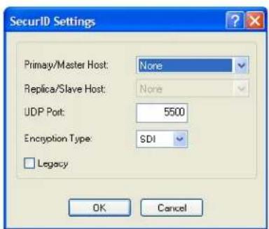
text_image
SecurlID Settings Primay/Master Host: None Replica/Slave Host: None UDP Port: 5500 Encryption Type: SDI Legacy OK CancelConfigure the following parameters:
Primary/Master Host The first SecurID server that is tried for user authentication. Default: None
Replica/Slave Host If the first SecurID server does not respond to an authentication request, this is the next SecurID server that is tried for user authentication. Default: None
UDP Port The port number that SecurID listens to for authentication requests. Default: 5500
Encryption Type The type of encryption that will be used for SecurID server communication.
Data Options: DES, SDI
Default: SDI
Legacy If you are running SecurID 3.x or 4.x, you need to run in Legacy Mode. If you are running SecurID 5.x or above, do not select Legacy Mode.
Default: Disabled
NIS
Field Descriptions
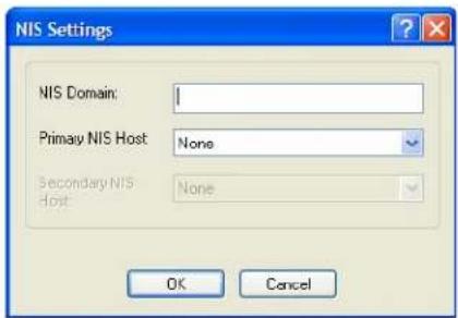
text_image
NIS Settings NIS Domain: Primary NIS Host None Secondary NIS host None OK CancelConfigure the following parameters:
NIS Domain The NIS domain name.
Primary NIS Host The primary NIS host that is used for authentication.
Default: None
Secondary NIS Host The secondary NIS host that is used for authentication, should the primary NIS host fail to respond.
Default: None
SSH
Overview
The IOLAN contains SSH Server software that you need to configure if the IOLAN is going to be accessed via SSH. If you specify more than one Authentication method and/or Cipher, the IOLAN will negotiate with the client and use the first authentication method and cipher that is compatible with both systems.
Functionality
When you are using the SSH connection protocol, keys need to be distributed to all users and the IOLAN. Below are a couple of example scenarios for key/certificate distribution.
Users Logging into the IOLAN Using SSH
This scenario applies to serial ports configured for Console Management using the SSH protocol. In the following example, users are connecting to the IOLAN via SSH from the LAN. Therefore, the following keys need to be exchanged:
- Upload the IOLAN SSH Public Key to each user's host machine who is connecting and logging into the IOLAN using SSH.
- Download the SSH Public Key from each user's host machine who is connecting and logging into the IOLAN using SSH.
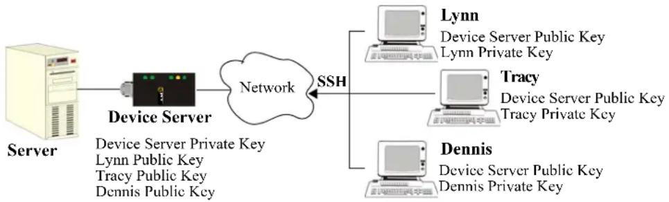
flowchart
graph LR
    Server --> DeviceServer["Device Server"]
    DeviceServer --> Network["Network"]
    Network --> SSH["SSH"]
    subgraph Cloud
        Cloud1["Lynn\nDevice Server Public Key\nLynn Private Key"]
        Cloud2["Tracy\nDevice Server Public Key\nTracy Private Key"]
        Cloud3["Dennis\nDevice Server Public Key\nDennis Private Key"]
    end
Users Passing Through the IOLAN Using SSH (Dir/Sil)
This scenario applies to serial ports configured for the Terminal profile and are required to login to the IOLAN. The user's service is set to the SSH protocol, therefore, users first log into the IOLAN and then are connected to a specified host (configured for the user when User Service SSH is selected) through an SSH connection. Lynn and Tracy automatically connect to the HR Server and Dennis automatically connects to the Development Server via SSH through the IOLAN. All the SSH negotiation is being done between the IOLAN and the target servers, therefore, the following keys need to be exchanged:
- Download the SSH Host Public Key to the IOLAN for each of the hosts that the IOLAN is connecting to.
- Download the SSH User Private Key for each user whose User Service is set to SSH.
- Copy the SSH User Public Key to the host that the user is connecting to (this is done outside the scope of the IOLAN).
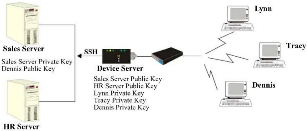
flowchart
graph LR
    A["HR Server"] -->|SSH| B["Device Server"]
    B --> C["Lynn"]
    B --> D["Tracy"]
    B --> E["Dennis"]
    A --> F["Sales Server\nSales Server Private Key\nDennis Public Key"]
    B --> G["Sales Server Public Key\nHR Server Public Key\nLynn Private Key\nTracy Private Key\nDennis Private Key"]
HR Server Private Key Lynn Public Key Tracy Public Key
Field Descriptions
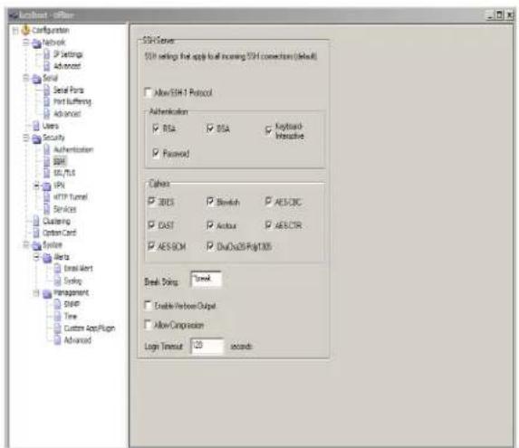
text_image
Configuration Network IP Settings Advanced Serial Serial Ports Print suffering Advanced Users Security Authentication SSH SSL/SSL IPs HTTP Tunnel Services Clustering Option Card System Beta Stream Alert Smiling Management Speed Time Custom App/Plug Advanced SSH Server SSH settings that apply to all increasing SSH connection (default) Allow SSH 1 Protocol Authentication BSA BSA Keyboard-Intercept Password Colors BRES Bootstrap AES-CRC CAST Android AES-CIR AES-ROM Data-DWG-Pig1005 Break Pins: Break Enable/Verber/Output Allow Composition Logx Timeout 120 secondsConfigure the following parameters:
Some combinations of cipher groups are not available on FIPS firmware versions. SSH-1 protocol is not available on FIPS firmware versions.
| Allow SSH-1Protocol | Allows the user's client to negotiate an SSH-1 connection, in addition to SSH-2.Default: Disabled |
| RSA | When a client SSH session requests RSA authentication, the IOLAN's SSH server will authenticate the user via RSA.Default: Enabled |
| DSA | When a client SSH session requests DSA authentication, the IOLAN's SSH server will authenticate the user via DSA.Default: Enabled |
| Keyboard-Interactive | The user types in a password for authentication.Default: Enabled |
| Password The user types in a password for authentication.Default: Enabled | |
| 3DES | The IOLAN SSH server's 3DES encryption is enabled/disabled.Default: Enabled |
| CAST | The IOLAN SSH server's CAST encryption is enabled/disabled.Default: Enabled |
| Blowfish | The IOLAN SSH server's Blowfish encryption is enabled/disabled.Default: Enabled |
| Arcfour The IOLAN SSH server's Arcfour encryption is enabled/disabled.Default: Enabled | |
| AES-CBC | The IOLAN SSH server's AES-CBC encryption is enabled/disabled.Default: Enabled |
| AES-CTR | The IOLAN SSH server's AES-CTR encryption is enabled/disabled.Default: Enabled |
| AES-GCM | The IOLAN SSH server's AES-GCM encryption is enabled/disabled.Default: Enabled |
| ChaCha20-Poly1305 | The IOLAN SSH server's ChaCha20-Poly1305 encryption is enabled/disabled.Default: Enabled |
| Break String | The break string used for inband SSH break signal processing. A break signal is generated on a specific serial port only when the server's break option is enabled and the user currently connected using reverse SSH has typed the break string exactly.Field Format: maximum 8 charactersDefault: ~break, where ~ is tilde |
| Enable Verbose Output | Displays debug messages on the terminal.Default: Disabled |
| Allow Compression | Requests compression of all data. Compression is desirable on modem lines and other slow connections, but will only degrade data transmission speeds on faster networks.Default: Disabled |
| Login Timeout | Set the time to wait for the SSH client to complete the login. If the timer expires before the login is completed, the session is terminated.Default: 120 secondsValues: 1-600 seconds |
SSL/TLS
Overview
When SSL/TLS is configured, data is encrypted between the IOLAN and the host/device (which must also support SSL/TLS). When you configure the SSL/TLS settings in the System section, you are configuring the default global SSL/TLS settings; you are not configuring an SSL/TLS server.
Functionality
You can create an encrypted connection using SSL/TLS for the following profiles: TruePort, TCP Sockets, Terminal (the user's Service must be set to SSL_Raw), Serial Tunneling, Virtual Modem, and Modbus.
When configuring SSL/TLS, the following configuration options are available:
- You can set up the IOLAN to act as an SSL/TLS client or server.
- There is an extensive selection of SSL/TLS ciphers that you can configure for your SSL/TLS connection; Appendix B, SSL/TLS Ciphers for a list of SSL/TLS ciphers.
Some combinations of cipher groups are not available on FIPS firmware versions.
- You can enable peer certificate validation, for which you must supply the validation criteria that was used when creating the peer certificate (this is case sensitive).
See Keys and Certificates for information about SSL/TLS support documents.
Field Descriptions
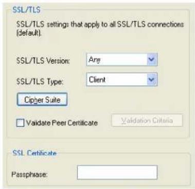
text_image
SSL/TLS SSL/TLS settings that apply to all SSL/TLS connections (default). SSL/TLS Version: Any SSL/TLS Type: Client Cipher Suite Validate Peer Certificate Validation Criteria SSL Certificate Passphrase:Configure the following parameters:
SSL/TLS Version
Specify whether you want to use:
- Any—The IOLAN will try a TLSv1 connection first. If that fails, it will try an SSLv3 connection. If that fails, it will try an SSLv2 connection.
- SSLv3—The connection will use only SSLv3.
- TLSv1—The connection will use only TLSv1.
- TLSv1.1—The connection will use only TLSv1.1.
• TLSv1.2—The connection will use only TLSv1.2.
Default: Any
SSL/TLS Type
Specify whether the IOLAN serial port will act as an SSL/TLS client or server.
Default: Client
Cipher Suite Button Click this button to specify SSL/TLS connection ciphers.
Validate Peer Certificate
Enable this option when you want the Validation Criteria to match the Peer Certificate for authentication to pass. If you enable this option, you need to download an SSL/TLS certificate authority (CA) list file to the IOLAN.
Default: Disabled
Validation Criteria Button
Click this button to create peer certificate validation criteria that must be met for a valid SSL/TLS connection.
SSL Certificate Passphrase
This is the SSL/TLS passphrase used to generate an encrypted RSA/DSA private key. This private key and passphrase are required for both HTTPS and SSL/TLS connections, unless an unencrypted private key was generated, then the SSL passphrase is not required. Make sure that you download the SSL private key and certificate if you are using the secure HTTP option (HTTPS) or SSL/TLS. If both RSA and DSA private keys are downloaded to the IOLAN, they need to be generated using the same SSL passphrase for both to work.
Cipher Suite Field Descriptions
Some combinations of cipher groups may not be available on some firmware versions.
The SSL/TLS cipher suite is used to encrypt data between the IOLAN and the client. You can specify up to five cipher groups.
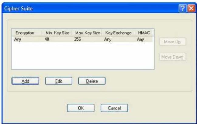
text_image
Cipher Suite Encryption Min. Key Size Max. Key Size Key Exchange HMAC Any 40 256 Any Any Move Up Move Down Add Edit Delete OK CancelThe following buttons are available on the Cipher Suite window:
Add Button Adds a cipher to the cipher list.
Edit Button Edits a cipher in the cipher list.
Delete Button Deletes a cipher from the cipher list.
Move Up Button Moves a cipher up in preference in the cipher list.
Move Down Button Moves a cipher down in preference in the cipher list.
Adding/Editing a Cipher
See Appendix B, SSL/TLS Ciphers for a list of valid SSL/TLS ciphers.
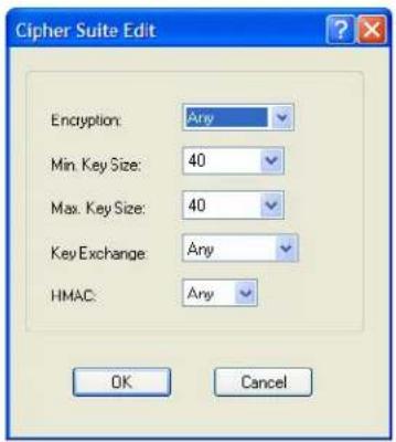
text_image
Cipher Suite Edit Encryption: Any Min. Key Size: 40 Max. Key Size: 40 Key Exchange: Any HMAC: Any OK CancelConfigure the following parameters:
| Encryption | Select the type of encryption that will be used for the SSL connection. Data Options: Any—Will use the first encryption format that can be negotiated. AES 3DES DES ARCFOUR ARCTWO AES-GCM Default:Any |
| Min Key Size | The minimum key size value that will be used for the specified encryption type. Data Options:40,56,64,128,168,256 Default:40 |
| Max Key Size | The maximum key size value that will be used for the specified encryption type. Data Options:40,56,64,128,168,256 Default:256 |
Key Exchange
The type of key to exchange for the encryption format.
Data Options:
- Any—Any key exchange that is valid is used (this does not, however, include ADH keys).
• RSA—This is an RSA key exchange using an RSA key and certificate. - EDH-RSA—This is an EDH key exchange using an RSA key and certificate.
- EDH-DSS—This is an EDH key exchange using a DSA key and certificate.
- ADH—This is an anonymous key exchange which does not require a private key or certificate. Choose this key if you do not want to authenticate the peer device, but you want the data encrypted on the SSL/TLS connection.
- ECDH-ECDSA—This is an ECDH key exchange using a ECDSA key and certificate.
Default: Any
HMAC
Select the key-hashing for message authentication method for your encryption type.
Data Options:
Any
MD5
SHA1
SHA256
SHA384
Default: Any
Validation Criteria Field Descriptions
If you choose to configure validation criteria, then the information in the peer SSL/TLS certificate must match exactly the information configured in this window in order to pass peer authentication and create a valid SSL/TLS connection.
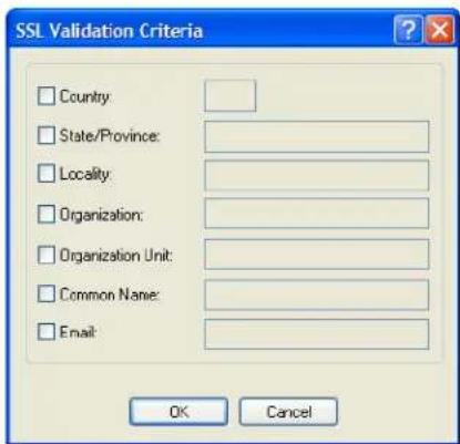
text_image
SSL Validation Criteria □ Country: □ State/Province: □ Locality: □ Organization: □ Organization Unit: □ Common Name: □ Email: OK CancelConfigure the following parameters:
Country
A country code; for example, US. This field is case sensitive in order to successfully match the information in the peer SSL/TLS certificate.
Data Options: Two characters
| State/Province | An entry for the state/province; for example, IL. This field is case sensitive in order to successfully match the information in the peer SSL/TLS certificate.Data Options: Maximum 128 characters |
| Locality | An entry for the location; for example, Chicago. This field is case sensitive in order to successfully match the information in the peer SSL/TLS certificate.Data Options: Maximum 128 characters |
| Organization | An entry for the organization; for example, Accounting. This field is case sensitive in order to successfully match the information in the peer SSL/TLS certificate.Data Options: Maximum 64 characters |
| Organization Unit | An entry for the unit in the organization; for example, Payroll. This field is case sensitive in order to successfully match the information in the peer SSL/TLS certificate.Data Options: Maximum 64 characters |
| Common Name An entry for common name; for example, the host name or fully qualified domain name. This field is case sensitive in order to successfully match the information in the peer SSL/TLS certificate.Data Options: Maximum 64 characters | |
| An entry for an email address; for example, acct@anycompany.com. This field is case sensitive in order to successfully match the information in the peer SSL/TLS certificate.Data Options: Maximum 64 characters |
VPN
Overview
A Virtual Private Network (VPN) creates a secure, dedicated communications network tunnelled through another network.
You can configure the IOLAN for:
- a host-to-host Virtual Private Network (VPN) connection
- a host-to-network VPN connection
• a network-to-network VPN connection - or host/network-to-IOLAN VPN connection (allowing serial devices connected to the IOLAN to communicate data to a host/network).
In addition to being able to configure up to 64 IPsec tunnels, you can configure an L2TP/IPsec tunnel that will allow hosts to create a VPN tunnel to the IOLAN. The L2TP/IPsec VPN protocol is required by the Windows XP ^® operating system. Later versions of Windows ^® may support both VPN protocols, however check with the Windows ^® documentation that came with your Windows ^® pc.
Before you enable/configure any VPN tunnels, you should configure any exceptions or you might not be able to access the IOLAN except through a VPN tunnel or the console port. See Exceptions for more information about exceptions.
Note: If you are configuring IPsec and/or L2TP/IPsec, you must also enable the IPsec service found in Security, Services navigation tree.
Functionality
The information in this section applies only to setting up IPsec VPN tunnels, not L2TP/IPsec VPN tunnels.
The IOLAN can be configured as a VPN gateway using the IPsec protocol. You can configure the VPN connection using two IOLANs as the local and remote VPN gateways or the IOLAN as the local VPN gateway and a host/server running the VPN software as the remote VPN gateway.
If the VPN tunnel is being configured for an IPv6 network that is going through a router(s), the router(s) must have manual IPv6 address entry capability, similar to what Windows Vista ^® provides.
VPN servers/clients can support various VPN parameters. However, the following parameters are REQUIRED to be set to the following values to support a VPN tunnel between the IOLAN and a VPN server/client:
perfect forward secrecy: no
protocol: ESP
mode: tunnel (not transport)
opportunistic encryption: no
aggressive mode: no
IKE Phase 1 Proposals
The following IKE Phase 1 proposals are supported by the IOLAN VPN gateway:
• Ciphers—3DES, AES
- Hashes—MD5, SHA1
- Diffie-Hellman Groups—2 (MODP1024), 5 (MODP1536), 14 (MODP2048), 15 (MODP3072), 16 (MODP4096), 17 (MODP6144), 18 (MODP8192)
ESP Phase 2 Proposals
The following ESP Phase 2 proposals are supported by the IOLAN VPN gateway:
• Ciphers—3DES, AES
• Authentication Algorithms—MD5, SHA1, SHA2
IPsec
When an IPsec tunnel becomes active, you are requiring that all access to the IOLAN go through the configured IPsec tunnel(s), so you must configure any exceptions first see (Exceptions). for more information on exceptions) or you will not be able to access the IOLAN through the network unless you are configured to go through the IPsec tunnel (you can still access the IOLAN through the Console port).
Field Descriptions
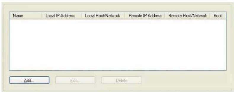
text_image
Name Local IP Address Local Host/Network Remote IP Address Remote Host/Network Boot Add... Edit... DeleteThe following buttons are available:
Add Button Click this button to add a new IPsec VPN tunnel.
Edit Button Select an existing IPsec VPN tunnel to edit the tunnel's parameters.
Delete Button Select an existing IPsec VPN tunnel to remove the tunnel.
Adding/Editing the IPsec Tunnel
When you click the Add button or select an IPsec tunnel and click the Edit button, the following window is displayed:
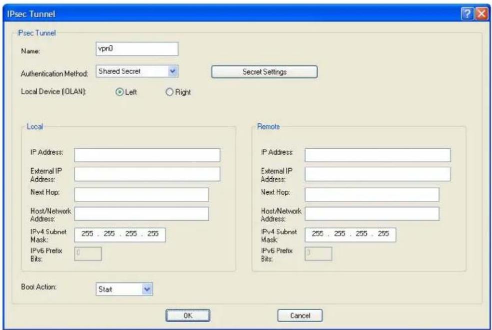
text_image
IPsec Tunnel IPsec Tunnel Name: vpn0 Authentication Method: Shared Secret Secret Settings Local Device (OLAN): Left Right Local IP Address: External IP Address: Next Hop: Host/Network Address: IPv4 Subnet Mask: 255 , 255 , 255 , 255 IPv6 Prefix Bits: 0 Remote IP Address: External IP Address: Next Hop: Host/Network Address: IPv4 Subnet Mask: 255 , 255 , 255 , 255 IPv6 Prefix Bits: 1 Boot Action: Start OK CancelConfigure the following parameters:
Name
Provide a name for the IPsec VPN tunnel to make it easy to identify.
Text Characteristics: Maximum of 16 characters, spaces not allowed
Authentication Method
Specify the authentication method that will be used between VPN peers to authenticate the VPN tunnel.
Data Options:
- Shared Secret—A text-based secret that is used to authenticate the IPsec tunnel (case sensitive). This applies to all VPN tunnels (IPsec and L2TP/IPsec).
- RSA Signature—RSA signatures are used to authenticate the IPsec tunnel. When using this authentication method, you must download the IPsec RSA public key to the IOLAN and upload the IPsec RSA public key from the IOLAN to the VPN gateway.
- X.509 Certificate—X.509 certificates are used to authenticate the IPsec tunnel. When using this authentication method, you must include the signing authority's certificate information in the SSL/TLS CA list and download it to the IOLAN.
Default: Shared Secret
| Secret/Remote Validation Criteria Button | Depending on the Authentication Method:Shared Secret—Specify the text-based secret that is used to authenticate the IPsec tunnel (case sensitive). This applies to all VPN tunnels (IPsec and L2TP/IPsec).X.509 Certificate—Specify the remote X.509 certificate validation criteria that must match for successful authentication (case sensitive). Note that all validation criteria must be configured to match the X.509 certificate. If using an asterisk (*) for wildcard matching, the Boot Action must be set to Add(Listen).See Shared Secret Field Description for more information.See Remote Validation Criteria Field Descriptions or more information on the X.509 certificate validation criteria. |
| Local Device | When the VPN tunnel is established, one side of the tunnel is designated as Right and the other as Left. You are configuring the IOLAN-side of the VPN tunnel.Data Options: Left, RightDefault: Left |
| Local IP Address | The IP address of the IOLAN. You can specify %defaultroute when the IP address of the IOLAN is not always known (for example, when it gets its IP address from DHCP). When %defaultroute is used, a default gateway must be configured in the route table (Network, Advanced, Route List tab).Field Format: IPv4 address, IPv6 address, FQDN, %defaultroute |
| Local External IP Address | When NAT Traversal (NAT_T) is enabled, this is IOLAN's external IP address or FQDN. When the IOLAN is behind a NAT router, this will be its public IP address.Field Format: IPv4 address, IPv6 address, FQDN |
| Local Next Hop | The IP address of the router/gateway that will forward data packets to the remote VPN (if required). The router/gateway must reside on the same subnet at the IOLAN. Leave this parameter blank if you want to use the Default Gateway configured in the IOLAN.Field Format: IPv4 or IPv6 address |
| Local Host/Network Address | The IP address of a specific host, or the network address that the IOLAN will provide a VPN connection to.Field Format: IPv4 or IPv6 address |
| Local IPv4 Subnet Mask | The subnet mask of the local IPv4 network. Keep the default value when you are configuring a host-to-host VPN connection.Default: 255.255.255.255 |
| Local IPv6 Prefix Bits | The prefix bits of the local IPv6 network. Keep the default value when you are configuring a host-to-host VPN connection.Default: 0 |
| Remote IP Address | The IP address or FQDN of the remote VPN peer. If you want to accept a VPN connection from any VPN peer, you can enter %any in this field.Field Format: IPv4 address, IPv6 address, FQDN, %any |
| Remote External IP Address | When NAT Traversal (NAT_T) is enabled, the remote VPN's public external IP address or FQDN.Field Format: IPv4 address, IPv6 address, FQDN |
| Remote Next Hop | The IP address of the router/gateway that will forward data packets to the IOLAN (if required). The router/gateway must reside on the same subnet at the remote VPN.Field Format: IPv4 or IPv6 address |
| Remote Host/Network Address | The IP address of a specific host or the network address that the IOLAN will provide a VPN connection to. If the IPsec tunnel is listening for connections (Boot Action set to Add), and the field value is left at 0.0.0.0, any VPN peer with a private remote network/host that conforms to RFC 1918 (10.0.0.0/8, 172.16.0.0./12, 192.168.0.0/16) will be allowed to use this tunnel if it successfully authenticates.Field Format: IPv4 or IPv6 address |
| Remote IPv4 Subnet Mask | The subnet mask of the remote IPv4 network. Keep the default value when you are configuring a host-to-host VPN connection.Default: 255.255.255.255 |
| Remote IPv6 Prefix Bits | The prefix bits of the remote IPv6 network. Keep the default value when you are configuring a host-to-host VPN connection.Default: 0 |
| Boot Action | Determines the state of the VPN network when the IOLAN is booted.Data Options:Start—Starts the VPN network, initiating communication to the remote VPN.Add—Adds the VPN network, but doesn’t initiate a connection to the remote VPN.Ignore—Maintains the VPN network configuration, but the VPN network is not started and cannot be started through the IPsec command option.When defining peer VPN gateways, one side should be defined as Start (initiate) and the other as Add (listen). It is invalid to define both gateways as Add. VPN connection time can take longer when both gateways are set to Start, as both sides will attempt to initiate the same VPN connection.Default: Start |
Shared Secret Field Description
When the Authentication Method is set to Shared Secret, you can enter a secret that applies to all VPN tunnels (both the IPsec and L2TP/IPsec protocols) to successfully authenticate and create a valid connection.
text_image
VPN Shared Secret This secret is global and applies to all VPN connections. Secret: OK CancelConfigure the following parameter:
Secret
When the Authentication Method is set to Shared Secret, enter the case-sensitive secret word. This applies to all VPN tunnels (IPsec and L2TP/IPsec).
Field Format: Maximum of 16 characters, spaces not allowed
Remote Validation Criteria Field Descriptions
When the Authentication Method is set to X.509 Certificate, you can configure the remote validation criteria. The information in the remote X.509 certificate must match exactly the information configured in this window in order to successfully authenticate and create a valid connection. If using an asterisk(*) for wildcard matching the Boot Action must be set to Add (Listen).
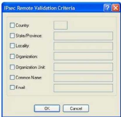
text_image
IPsec Remote Validation Criteria Country: State/Province: Locality: Organization: Organization Unit: Common Name: Email: OK CancelConfigure the following parameters:
| Country | A country code; for example, US. This field is case sensitive in order to successfully match the information in the remote X.509 certificate. |
| Data Options: Two characters, If using an asterisk (*) for wildcard matching, the Boot Action must be set to Add (Listen). | |
| State/Province | An entry for the state/province; for example, IL. This field is case sensitive in order to successfully match the information in the remote X.509 certificate. |
| Data Options: Maximum 128 characters, If using an asterisk (*) for wildcard matching, the Boot Action must be set to Add (Listen). | |
| Locality | An entry for the location; for example, Chicago. This field is case sensitive in order to successfully match the information in the remote X.509 certificate. |
| Data Options: Maximum 128 characters, If using an asterisk(*) for wildcard matching, the Boot Action must be set to Add (Listen). | |
| Organization | An entry for the organization; for example, Accounting. This field is case sensitive in order to successfully match the information in the remote X.509 certificate. |
| Data Options: Maximum 64 characters, If using an asterisk(*) for wildcard matching the Boot Action must be set to Add (Listen). | |
| Organization Unit | An entry for the unit in the organization; for example, Payroll. This field is case sensitive in order to successfully match the information in the remote X.509 certificate. |
| Data Options: Maximum 64 characters, If using an asterisk (*) for wildcard matching, the Boot Action must be set to Add (Listen). | |
| Common Name An entry for common name; for example, the host name or fully qualified domain name. This field is case sensitive in order to successfully match the information in the remote X.509 certificate. | |
An entry for an email address; for example, acct@anycompany.com. This field is case sensitive in order to successfully match the information in the remote X.509 certificate.
Data Options: Maximum 64 characters, If using an asterisk (*) for wildcard matching, the Boot Action must be set to Add (Listen).
L2TP/IPsec
In order to create a VPN tunnel on Windows XP ^® , you must use the L2TP/IPsec protocol. When L2TP/IPsec is enabled, the IOLAN will listen for L2TP/IPsec VPN tunnel requests.
When you enable L2TP/IPsec, you are requiring that all access to the IOLAN go through the L2TP/IPsec tunnel, so you must configure any exceptions first see (Exceptions) for more information on exceptions) or you will not be able to access the IOLAN through the network unless you are configured to go through the L2TP/IPsec tunnel (you can still access the IOLAN through the Console port).
Field Descriptions
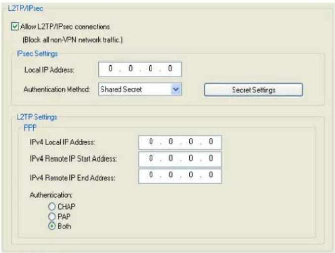
text_image
L2TP/IPsec Allow L2TP/IPsec connections (Block all non-VPN network traffic.) IPsec Settings Local IP Address: 0 . 0 . 0 . 0 Authentication Method: Shared Secret Secret Settings L2TP Settings PPP IPv4 Local IP Address: 0 . 0 . 0 . 0 IPv4 Remote IP Start Address: 0 . 0 . 0 . 0 IPv4 Remote IP End Address: 0 . 0 . 0 . 0 Authentication: ○ CHAP ○ PAP ○ BothConfigure the following parameters:
Allow L2TP/IPsec connections
When enabled, the IOLAN listens for L2TP/IPsec VPN tunnel connections. Note: to allow non-VPN tunnel connections to the IOLAN, you must create entries in the VPN Exceptions list.
Default: Disabled
Local IP Address
If the IPsec local address is set to 0.0.0.0, the IOLAN will listen for L2TP/IPsec connections on (the IP address of) the network interface associated with (ie: on the same network as) the IOLAN's default gateway. If no default gateway exists, the IOLAN will not listen for L2TP/IPsec connections.
Default: 0.0.0.0
| Authentication Method | Specify the authentication method that will be used between VPN peers to authenticate the VPN tunnel. Data Options: Shared Secret—A text-based secret that is used to authenticate the IPsec tunnel (case sensitive). X.509 Certificate—X.509 certificates are used to authenticate the IPsec tunnel. When using this authentication method, you must include the signing authority's certificate information in the SSL/TLS CA list and download it to the IOLAN. Default: Shared Secret |
| Remote Validation Criteria | Depending on the Authentication Method: Shared Secret—Specify the text-based secret that is used to authenticate the IPsec tunnel (case sensitive). This applies to all VPN tunnels (IPsec and L2TP/IPsec). X.509 Certificate—Specify the remote X.509 certificate validation criteria that must match for successful authentication (case sensitive). Note that all validation criteria must be configured to match the X.509 certificate. If using an asterisk (*) for wildcard matching, the Boot Action must be set to Add (Listen). See Shared Secret Field Description for more information. See Remote Validation Criteria Field Descriptions or more information on the X.509 certificate validation criteria. |
| IPv4 Local IP Address | Specify the unique IPv4 address that hosts accessing the IOLAN through the L2TP tunnel will use. Field Format: IPv4 address |
| IPv4 Remote IP Start Address | Specify the first IPv4 address that can be assigned to incoming hosts through the L2TP tunnel. Field Format: IPv4 address |
| IPv4 Remote IP End Address | Specify the end range of the IPv4 addresses that can be assigned to incoming hosts through the L2TP tunnel. Field Format: IPv4 address |
| Authentication | Specify the authentication method that will be used for the L2TP tunnel. Data Options: CHAP, PAP, Both Default: Both |
Exceptions
Exceptions allow specific hosts or any host in a network to access the IOLAN outside of a VPN tunnel. This is especially useful when allowing local network hosts access to the IOLAN when VPN tunnels have been configured for remote user security.
Field Descriptions
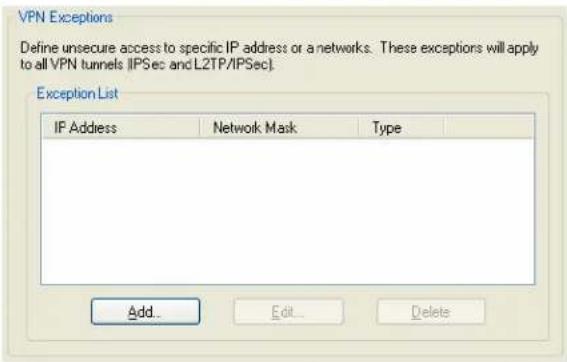
text_image
VPN Exceptions Define unsecure access to specific IP address or a networks. These exceptions will apply to all VPN tunnels [IPSec and L2TP/IPSec]. Exception List IP Address Network Mask Type Add Edit DeleteThe following buttons are available:
Add Button Click the Add button to add a VPN exception to the Exception List.
Edit Button Highlight an Exception List entry and click the Edit button to change the entry.
Delete Button Highlight an Exception List entry and click the Delete button to remove the entry from the list.
Adding/Editing a VPN Exception
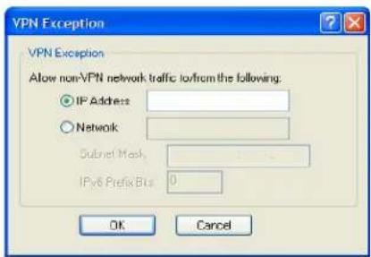
text_image
VPN Exception Allow non-VPN network traffic to/from the following: IP Address Network Subnet Mask IPv6 Prefix Bus 0 OK CancelThe following parameters are available:
IP Address The IP address of the host that will communicate with the IOLAN outside of the VPN tunnel.
Field Format: IPv4 or IPv6 address
Network The network address that will communicate with the IOLAN outside of the VPN tunnel.
Field Format: IPv4 or IPv6 address
IPv4 Subnet Mask The IPv4 subnet mask for the IPv4 network.
Default: 0.0.0.0
IPv6 Prefix Bits The IPv6 prefix bits for the IPv6 network.
Range: 0-128
Default: 0
Advanced
Field Description
IPsec Settings
These settings are global and apply to all VPN connections.
Use NAT Traversal (NAT_T)
Configure the following parameter:
Use NAT Traversal (NAT_T)
NAT Traversal should be enabled when the IOLAN is communicating through a router/gateway to a remote VPN that also has NAT Traversal enabled.
Default: Enabled
HTTP Tunneling
Overview
A HTTP tunnel is a firewall-safe communication channel between two IOLAN's. HTTP tunnels can transport arbitrary TCP/IP or UDP/IP data for applications such as Telnet/SSH or any other TCP application and most UDP applications.
You can configure the IOLAN for:
- a serial-to-serial HTTP tunnel connection
- a serial-to-host HTTP tunnel connection
- a host-to-host HTTP tunnel connection
- Tunnel Relay connection
See Configuring HTTP Tunnels for more information on setup requirements for these scenarios.
Functionality
The information in this section applies only to setting up HTTP tunnels.
A minimum of two IOLAN's must be configured to create a communication channel. One IOLAN must be configured as the listener and the other IOLAN must be configured as the connecting IOLAN.
Adding/Editing the HTTP Tunnel
Field Descriptions
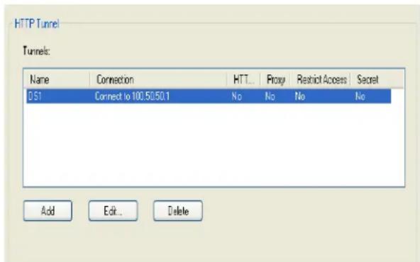
text_image
HTTP Tunnel Tunnels: Name Connection HTT... Proxy Restrict Access Secret DS1 Connect to 100.50.50.1 No No No No Add Edit... DeleteThe following buttons are available:
Add Button Click the Add button to add an HTTP Tunnel entry to the list.
Edit Button Highlight an HTTP Tunnel entry and click the Edit button to change the entry.
Delete Button Highlight an HTTP Tunnel entry and click the Delete button to remove the entry from the list.
Configuring HTTP Tunnel
Field Descriptions
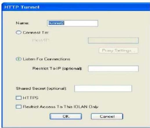
text_image
HTTP Tunnel Name: tunnel2 Connect To: Host/IP Proxy Settings... Listen For Connections Restrict To IP (optional): Shared Secret (optional): HTTPS Restrict Access To This IOLAN Only OK CancelThe following parameters are available for configuring a HTTP Tunnel.
| Name | Provide a name for this tunnel. This name must match the tunnel name on the tunnel peer IOLAN DS. |
| Connect to | Provide the Host name or IP address of the listening IOLAN DS. |
| Proxy Settings | If a proxy server is being used, allows for the configuration of proxy specific parameters. |
| Listen for Connections | Listen for connection requests generated from the connecting IOLAN DS |
| Restrict to IP | Only accept connection requests from this IP address |
| Shared Secret | If a secret is defined, then both sides of the tunnel must set the same secret. A secret is used to ensure that the Tunnel is being established with the correct peer. |
| HTTPS | When enabled, secure access mode (HTTPS) will be used to establish the tunnel. |
| Restrict Access to this IOLAN only | If enabled, tunnel connections will only be allowed to access local devices (serial ports) on this IOLAN. Connection requests going to external IP hosts on the local LAN will be not allowed. |
HTTPS mode requires that the SSL Passphrase is already defined in the IOLAN configuration and the SSL/TLS certificate/private key and CA list must have already been downloaded to the IOLAN; see Keys and Certificates for more information.
Configuring HTTP Tunnel Proxy
Proxy servers are used in larger companies and organizations. Ask your network administrator if you need to configure a Proxy server.
Field Descriptions
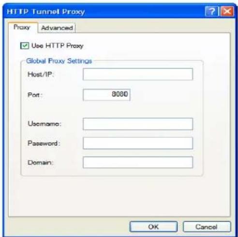
text_image
HTTP Tunnel Proxy Proxy Advanced Use HTTP Proxy Global Proxy Settings Host/IP: Port: 8000 Username: Password: Domain: OK CancelThe following parameters are available for configuring the Proxy specific parameters.
Use HTTP Proxy Enables the Proxy parameters.
Host/IP The Host name or IP address of the Proxy server.
Port The HTTP/HTTPS port number of the Proxy server. Default: 8080.
Username The "username" which will be used by the Terminal Server to authenticate with the proxy server (if authentication is required by the proxy server).
Password The "password" which will be used by the Terminal Server to authenticate with the proxy server (if authentication is required by the proxy server).
Domain This field is only used if authentication is needed with the proxy server. If the proxy server does not expect this field, it can be left blank.
We support the following types of authentication; Local Windows account authentication (clear text, SPA) and Digest authentication (MD5).
Ensure that your Proxy Server does not restrict HTTP-CONNECT messages to port 443 and allows HTTP-CONNECT messages on Port 80
Configuring HTTP Tunnel Proxy Advanced
Field Descriptions
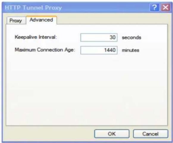
text_image
HTTP Tunnel Proxy Proxy Advanced Keepalive Interval: 30 seconds Maximum Connection Age: 1440 minutes OK CancelKeepalive Interval
The number of seconds between sending keepalives for HTTP connections. Keepalives are used to prevent idle connections from closing. In most cases this value does not need to be changed.
Default: 30 seconds
Maximum
Connection Age
The maximum amount of time an HTTP connection will stay open in minutes. In most cases this value does not need to be changed.
Default: 1440 mins. (1 day).
Configuring HTTP Tunnel Destination
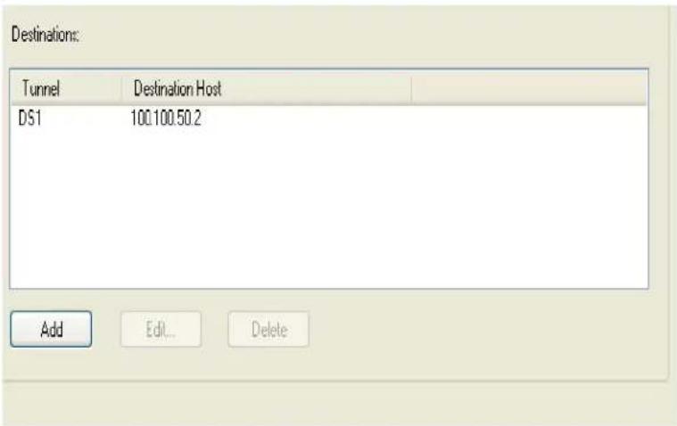
text_image
Destination: Tunnel Destination Host DS1 100.100.50.2 Add Edit... DeleteThe following buttons are available.
Add Button
Click the Add button to add an HTTP Tunnel Destination entry to the list.
Edit Button
Highlight an HTTP Tunnel Destination entry and click the Edit button to change the entry.
Delete Button
Highlight an HTTP Tunnel Destination entry and click the Delete button to remove the entry from the list.
Field Descriptions
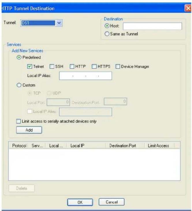
text_image
HTTP Tunnel Destination Tunnel: DS1 Destination Host: Same as Tunnel Services Add New Services Piedefined Telnet SSH HTTP HTTPS Device Manager Local IP Alias: Custom TCP UDP Local Port: 0 Destination Port: 0 Local IP Alias: Limit access to serially attached devices only Add Protocol Serv... Local... Local IP Destination Port Limit Access Delete OK CancelConfigure the following parameters if host access via a tunnel is needed. Each entry in the list box defines the application and port numbers an external client will use to access the destination host or application.
Tunnel
Select the HTTP tunnel to use for this connection
Destination
The address of an external host on the peer IOLAN's LAN. If the destination is a serial port on the Peer IOLAN or the peer IOLAN itself, select "Same as Tunnel".
Add new Services
Select either predefined services or custom services.
Predefined Services
Select the service or services required. For predefined services, you must specify an alias local IP address which will be used by the external host to access the service.
Custom Services
Selecting custom services allows you to enter in a custom application configuration. Select either TCP or UDP.
Local Port
The listening TCP/IP or UPD/IP port. This is the port the local host will be using.
| Destination Port | The port number used by the destination host or destination application. |
| Local IP Alias | Users can access the HTTP tunnel through this IP address. Typically this field is only needed if the IOLAN has a listener on the same local TCP port. If not entered, the IP address of the IOLAN is used. |
| Limited access to attached serial devices only | Allow only attached serial devices to connect to this destination. |
| Add button | Acts like an "apply" button. |
| Delete button | Highlight an HTTP Tunnel Destination entry and click the Delete button to remove the entry from the list. |
When HTTP tunneling is used TCP and UDP ports 50,000 and above are reserved and should not be configured by the user.
Services
Overview
Services are either daemon or client processes that run on the IOLAN. You can disable any of the services for security reasons.
Functionality
If you disable any of the daemons, it can affect how the IOLAN can be used or accessed. For example, if you disable WebManager (HTTPS and HTTP) services, you will not be able to access the IOLAN with the WebManager. If you disable the DeviceManager service, the DeviceManager will not be able to connect to the IOLAN. If you do not want to allow users to Telnet to the IOLAN, you can disable the Telnet Server service; therefore, disabling daemons can also be used as an added security method for accessing the IOLAN.
By default, all daemon and client applications are enabled, except IPsec, and running on the IOLAN.
Field Descriptions
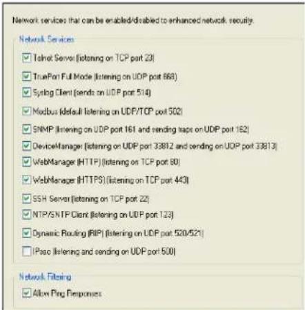
text_image
Network services that can be enabled/disabled to enhanced network security. Network Services ✓ Telnet Server (listening on TCP port 23) ✓ TruePort Full Mode (listening on UDP port 668) ✓ Syslog Client (sends on UDP port 514) ✓ Modbus (default listening on UDP/TCP port 502) ✓ SNMP (listening on UDP port 161 and sending traps on UDP port 162) ✓ DeviceManager (listening on UDP port 33812 and sending on UDP port 33813) ✓ WebManager (HTTP) (listening on TCP port 80) ✓ WebManager (HTTPS) (listening on TCP port 440) ✓ SSH Server (listening on TCP port 22) ✓ NTP/SNTP Client (listening on UDP port 123) ✓ Dynamic Routing (RIP) (listening on UDP port 520/521) ✓ IPsec (listening and sending on UDP port 500) Network Filming ✓ Allow Ping ResponsesEnable/disable the following options:
Telnet Server Telnet daemon process in the IOLAN listening on TCP port 23.
Default: Enabled
TruePort Full Mode
The TruePort daemon process in the IOLAN that supports TruePort Full Mode on UDP port 668. You can still communicate with the IOLAN in Lite Mode when this service is disabled.
Default: Enabled
Syslog Client Syslog client process in the IOLAN.
Default: Enabled
Modbus Modbus daemon process in the IOLAN listening on port 502.
Default: Enabled
SNMP SNMP daemon process in the IOLAN listening on UDP port 161 and sending traps on UDP port 162.
Default: Enabled
| DeviceManager | DeviceManager daemon process in the IOLAN. If you disable this service, you will not be able to connect to the IOLAN with the DeviceManager application. The DeviceManager listens on port 33812 and sends on port 33813.Default: Enabled |
| WebManager (HTTP) | WebManager daemon process in the IOLAN listening on port 80.Default: Enabled |
| WebManager (HTTPS) | Secure WebManager daemon process in the IOLAN listening on port 443.Default: EnabledIf you are using the WebManager in secure mode (HTTPS), you need to download the SSL/TLS private key and certificate to the IOLAN. You also need to set theSSL Passphraseparameter with the same password that was used to generate the key. SeeKeys and Certificatesfor more information. |
| SSH Server SSH daemon process in the IOLAN listening on TCP port 22.Default: Enabled | |
| NTP/SNTP Client | Simple Network Time Protocol client process in the IOLAN. NTP/SNTP client listens on UDP port 123.Default: Enabled |
| Dynamic Routing (RIP) | Dynamic Routing daemon process in the IOLAN listening on port 520/521.Default: Enabled |
| IPsec IPsec daemon process in the IOLAN listening and sending on UDP port 500.Default: Disabled | |
| Allow Ping Responses | The IOLAN will respond to incoming pings.Default: Enabled |
TCP ports 2601, 2602 and 2603 are used internally by the IOLAN.
Keys and Certificates
When you are using SSH, SSL/TLS, LDAP/Microsoft Active Directory, or HTTPS, you will need to install keys and/or certificates or get server keys in order to make those options work properly. All certificates need to be created and all keys need to be generated outside of the IOLAN, with the exception of the IOLAN SSH Public keys, which already exist in the IOLAN. SSH keys must be generated using the OpenSSH format.
Certificate Authorities (CAs) such as Verisign, COST, GTE CyberTrust, etc. can issue certificates. Or, you can create a RSA or DSA self-signed certificate using a utility such as OpenSSL.
To download or keys, a certificate, or a CA list or to upload the IOLAN public SSH key, select Tools, Advanced, Keys and Certificates.
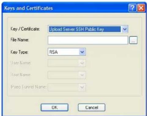
text_image
Keys and Certificates Key / Certificate: Upload Server SSH Public Key File Name: Key Type: RSA User Name: Host Name: Pseq / tunnel Name: OK CancelThe following fields are available:
Key / Certificate
Select the key or certificate that you want to download to the IOLAN or upload the Management Module's SSH Public Key.
Data Options:
- Upload Server SSH Public Key, used for SSH management access
• Download SSH User Public Key, used for SSH management access - Download SSL/TLS Private Key, required if using HTTPS and/or SSL/TLS
• Download SSH Host Public Key, required if using SSH
• Download SSL/TLS Private Key, required if using SSL/TLS - Download SSL/TLS Certificate, required if using HTTPS and/or SSL/TLS
- Upload IPsec RSA Public Key, required if using X.509 certification authentication for an IPsec tunnel
- Download IPsec RSA Public Key, required if using X.509 certification authentication for an IPsec tunnel
- Download SSL/TLS CA, required if using LDAP/Microsoft Active Directory with TLS, SSL/TLS, and/or X.509 certificate authentication for an IPsec tunnel
- Download NTP/SNTP Keys File, required if using NTP/SNTP server authentication
File Name The file that you are going to download/upload to/from the IOLAN via TFTP.
Key Type Specify the type of authentication that will be used for the SSH session. The following list details the keys that support each key type.
Data Options:
- RSA—Server SSH Public Key, SSH User Public Key, SSH User Private Key, SSH Host Public Key
- DSA—Server SSH Public Key, SSH User Public Key, SSH User Private Key, SSH Host Public Key
User Name The name of the user for whom you are downloading the SSH User Public or Private Key to the IOLAN.
Host Name The name of the host for which you are downloading the SSH Host Public or Private Key to the IOLAN.
IPsec Tunnel Name Select the IPsec tunnel that the RSA public key is being used to authenticate.

text_image
9Configuring I/O Interfaces
Introduction
There is a line of IOLANs that can control/monitor the following types of I/O:
- Analog Input
Digital Input/Output - Relay Output
• Temperature Input
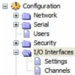
text_image
Configuration + Network + Serial + Users + Security - I/O Interfaces Settings ChannelsSome of the models are I/O combinations and some of the models support one I/O type, although all of the SDS I/O models are extensions of the feature rich SDS IOLAN.
Technical Specifications
Digital I/O
• 2 or 4 channels depending on model
- software selectable as inputs or outputs
• optical isolation of 2000V rms
Digital Input
- Dry Contact: Logic 0 = open. Logic 1 = close to GND
- Wet Contact: Logic 0 = 0-3VDC. Logic 1 = 10V-30VDC
Digital Output
- Open collector to 30VDC (source, sink or both)
- 200mA max load
• Digital out (DO) or pulse mode
Relay
- Form C type SPDT
- Contact rating: 1A@30VDC, 0.5A@AC: 120VAC
• Breakdown voltage: 500 VAC (50/60 Hz) - Relay on time: 7 msec. Relay off time 3 msec
• Total switching time: 10 msec
• Insulation resistance: 1000 MW minimum at 500 VDC
Settings
Overview
The I/O Interfaces Settings window configures the parameters that are global to all I/O channels.
I/O Access Functionality
Field Descriptions
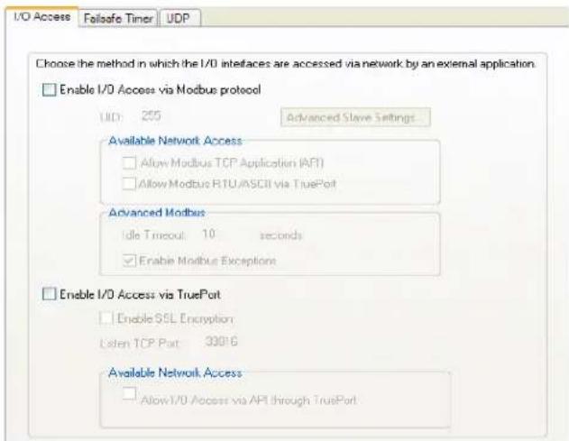
text_image
I/O Access Folisafe Timer UDP Choose the method in which the I/O interfaces are accessed via network by an external application. Enable I/O Access via Modbus protocol IID: 255 Advanced Slave Settings Available Network Access Allow Modbus TCP Application (API) Allow Modbus RTU/ASCII via TruePort Advanced Modbus Idle Timeout: 10 seconds Enable Modbus Exceptions Enable I/O Access via TruePort Enable SSL Encryption Listen TCP Port: 33916 Available Network Access Allow I/O Access via API through TruePortConfigure the following parameters:
Enable I/O Access Enables/disables Modbus as the communication protocol for all the I/O to Modbus protocol channels.
Default: Disabled
UID This is the UID you are assigning to the IOLAN, which is acting as a Modbus slave.
Default: 255
Advanced Modbus Click this button to configure global Modbus Slave settings.
Settings Button
See Advanced Slave Modbus Settings on page 179 for field descriptions.
Allow Modbus TCP Allows a host running a Modbus/TCP application to communicate to the I/O Application (API) channels using the standard Modbus API.
Default: Permanently enabled when Enable I/O Access via Modbus protocol is enabled
See Modbus I/O Access on page 210 for function codes and I/O coil/registration descriptions.
Allow Modbus RTU/ASCII via Enables/disables serial Modbus application access to the I/O over the network using the TruePort COM redirector feature.
TruePort
Default: Disabled
See Modbus I/O Access on page 210 for function codes and I/O coil/registration descriptions and Accessing I/O Data Via TruePort on page 217 for the Perle API.
| Enable I/O Access via TruePort | Enables/disables serial application access to the I/O over the network using the TruePort COM redirector feature.Default: Disabled |
| Enable SSL Encryption | Enables/disables SSL encryption for the I/O data between the IOLAN and the TruePort host.Default: Disabled |
| Listen TCP Port | The TCP port that the IOLAN will listen to for I/O channel data requests from TruePort.Default: 33816 |
| Allow I/O Access via API through TruePort | Allows serial application access to the I/O over the network using the TruePort COM redirector feature via a custom application using the Perle API.Default: Permanently enabled when Enable I/O Access via TruePort is enabledSee Modbus I/O Access on page 210 for function codes and I/O coil/registration descriptions and Accessing I/O Data Via TruePort on page 217 for the Perle API. |
Advanced Slave Modbus Settings
The parameters in this window configure global Modbus gateway settings that apply to all serial ports configured first as the Modbus Gateway profile and then as a Modbus Slave.
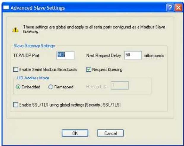
text_image
Advanced Slave Settings These settings are global and apply to all serial ports configured as a Modbus Slave Gateway. Slave Gateway Settings TCP/UDP Port: 500 Next Request Delay: 50 milliseconds Enable Serial Modbus Broadcasts Request Queuing UID Address Mode Embedded Remapped Recap UID: 1 Enable SSL/TLS using global settings (Security-)SSL/TLS) OK CancelConfigure the following parameters:
TCP/UDP Port The network port number that the Slave Gateway will listen on for both TCP and UDP messages.
Default: 502
Next Request Delay A delay, in milliseconds, to allow serial slave(s) to re-enable receivers before issuing next Modbus Master request.
Range: 0-1000
Default: 50 ms
Enable Serial When enabled, a UID of 0 (zero) indicates that the message will be broadcast to Modbus Broadcasts all Modbus Slaves.
Default: Disabled
Request Queuing When enabled, allows multiple, simultaneous messages to be queued and processed in order of reception.
Default: Enabled
Embedded When this option is selected, the address of the slave Modbus device is embedded in the message header.
Default: Enabled
Remapped Used for single device/port operation. Older Modbus devices may not include a UID in their transmission header. When this option is selected, you can specify the UID that will be inserted into the message header for the Modbus slave device. This feature supersedes the Broadcast feature.
Default: Disabled
Remap UID Specify the UID that will be inserted into the message header for the Slave Modbus serial device.
Range: 1-247
Default: 1
Enable SSL/TLS When enabled, Modbus Slave Gateway messages to remote TCP Modbus using global settings Masters are encrypted via SSL/TLS.
Default: Disabled
Failsafe Timer Functionality
Overview
The Failsafe Timer tab configures the I/O failsafe timer. The Failsafe Timer is enabled on a global basis and provides a trigger mechanism that can be configured for each channel when no I/O traffic/management has occurred for the specified amount of time. A Failsafe Action can be configured for each Digital Output channel, each Serial Signal Output pin (DTR and RTS), and each Relay channel to either Activate or Deactivate the output.
The Failsafe Timer has a different function when I/O Extension is enabled for Digital Output channels, Relay channels, or the Serial Signal Output pins (DTR and RTS). For I/O Extension, the Failsafe Timer provides a per channel or per serial signal output pin trigger mechanism that is activated when there are no TCP sessions for the specified amount of time.
Field Descriptions
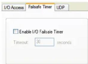
text_image
I/O Access Failsafe Timer UDP Enable I/O Failsafe Timer Timeout: 30 secondsConfigure the following parameters:
Enable I/O Failsafe Timer Enables/disables the Failsafe Timer. This is the global setting that must be enabled to set the Failsafe Action on the channel for digital output and relay channels or output signal pins. When this timer expires because of no I/O activity within the specified time interval, the Failsafe Action set for the channel determines the action on the output. When the channel or serial signal pin is configured for I/O extension, the timer expires there are no TCP sessions for the specified time interval.
Default: Disabled
Timeout The number of seconds that must elapse before the channel/serial signal pin Failsafe Action is triggered.
Range: 1-9999
Default: 30 seconds
UDP Functionality
Overview
The UDP tab configures the I/O UDP broadcast settings. The I/O UDP broadcast feature periodically broadcasts the I/O channel status in a UDP message.
You can configure up to four sets of IP address entries (each entry consisting of a start and end IP address range) to broadcast I/O status data. The broadcast frequency of the UDP packets to the configured UDP IP addresses can be defined to accommodate network traffic and monitoring PC application requirements. For details of the UDP I/O datagram see I/O UDP on page 206.
Field Descriptions
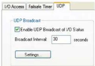
text_image
I/O Access Failsafe Timer UDP UDP Broadcast Enable UDP Broadcast of I/O Status Broadcast Interval: 30 seconds Settings...Configure the following parameters:
Enable UDP Enables/disables UDP broadcast of I/O channel status (data).
Broadcast of I/O Default: Disabled Status
Broadcast Interval Enter the interval, in seconds, for UDP broadcasts of I/O channel status (data).
Range: 1-9999
Default: 30 seconds
Settings Button Click this button to configure the UDP IP addresses that will receive the I/O status information.
See I/O UDP Settings on page 183 for field descriptions for the I/O UDP Settings window.
I/O UDP Settings
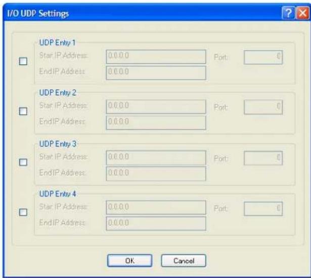
text_image
I/O UDP Settings UDP Entry 1 Start IP Address: 0.0.0 Port: 0 EndIP Address: 0.0.0 UDP Entry 2 Start IP Address: 0.0.0 Port: 0 EndIP Address: 0.0.0 UDP Entry 3 Start IP Address: 0.0.0 Port: 0 EndIP Address: 0.0.0 UDP Entry 4 Start IP Address: 0.0.0 Port: 0 EndIP Address: 0.0.0 OK CancelConfigure the following parameters:
UDP Entry When enabled, broadcasts I/O status (data) to the specified range of IP addresses.
Default: Disabled
Start IP Address The first host IP address in the range of IP addresses (for IPV4 or IPV6) that the IOLAN will listen for messages from and/or send messages to.
Field Format: IPv4 or IPv6 address
End IP Address The last host IP address in the range of IP addresses (for IPV4, not required for IPV6) that the IOLAN will listen for messages from and/or send messages to.
Field Format: IPv4 address
Port The UDP port that the IOLAN will use to relay messages to servers/hosts.
Default: 0 (zero)
Temperature Functionality
Overview
The Temperature tab configures the temperature scale settings for T4 models.
Field Descriptions
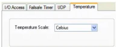
text_image
I/O Access Failsafe Timer UDP Temperature Temperature Scale: CelsiusConfigure the following parameter:
Temperature Scale Select the temperature scale that will be used to display temperature data.
Data Options: Fahrenheit or Celsius
Default: Celsius
Channels
The Channels section displays the I/O Channels window, through which you can enable/disable the I/O channels.
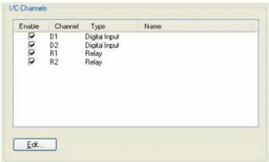
text_image
I/O Channels Enable Channel Type Name ✓ D1 Digital Input ✓ D2 Digital Input ✓ R1 Relay ✓ R2 Relay Edit...Highlight a channel and then click the Edit button to configure the parameters for that channel.
Analog
Overview
Analog channels monitor current/voltage input. Note that the internal jumpers must match the software setting (by default, they are set to Current); see Analog Input Module on page 431 to find out how to set the internal jumpers.
For example, in an industrial freezer warehouse, the IOLAN A4R2 is used to monitor humidity transducers, which are in place to help prevent freezer burn. If the humidity reaches a certain percentage (monitored by an Analog channel) a syslog message is sent to the Monitoring Application. The Monitoring Application then sends a command to the IOLAN via the Perle API that causes the Relay channel to activate an internal freezer dehumidifier. The relay is turned off when the Analog channel sends a clear syslog message to the Monitoring Application and the Relay channel is deactivated.
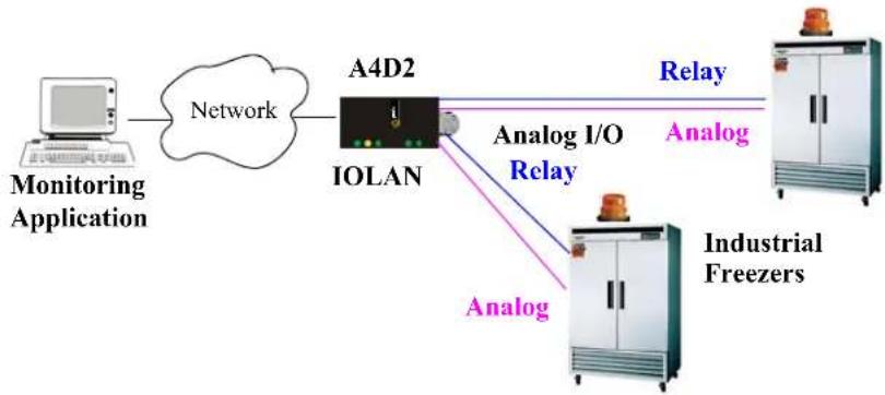
flowchart
graph LR
    A["Monitoring Application"] --> B["Network"]
    B --> C["A4D2 IOLAN"]
    C --> D["Relay"]
    C --> E["Analog I/O Relay"]
    E --> F["Industrial Freezers"]
    C --> G["Analog"]
Field Descriptions
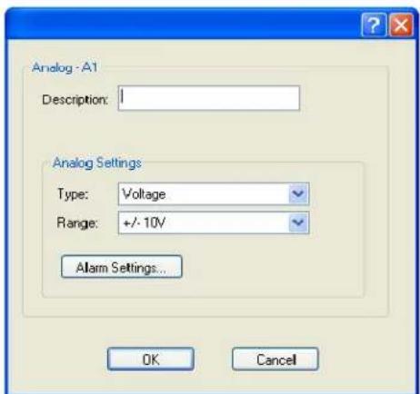
text_image
Analog - A1 Description: 1 Analog Settings Type: Voltage Range: +/- 10V Alarm Settings... OK CancelConfigure the following parameters:
Description Provide a description of the channel, making it easier to identify.
Data Options: Maximum 20 characters, including spaces
Type Select the type of input being measured.
Data Options: Current or Voltage
Default: Current
Range Select the range for the measurement type.
Data Options:
• Current—0-20 mA, 4-20 mA
Voltage—+/- 10V, +/- 5V, +/- 1V, +/- 500mV, +/- 150mV
Default: Current is 0-20 mA. Voltage is +/- 10V.
Alarm Settings Button Click the Alarm Settings button to specify the trigger and clear levels for the alarms. Notice that the Analog Alarm Settings window has two alarm configuration views, a basic alarm view and an advanced alarm view.
See Alarm Settings on page 203 for field descriptions.
Digital Input
Overview
When the channel is set for digital input, it monitors voltage or current. Note that the internal jumpers must match the software setting and must be set to Input, which is the default; see Digital I/O Module on page 431 to find out how to set the internal jumpers.
Functionality
The Digital input channels allow you to configure the following options:
- You can choose to remember the last state change, or latch, that occurred. Your options are to latch (remember) when the state changes from inactive to active or active to inactive.
- You can choose to invert the signal, which is useful if your sensor is wired in such a way that closed is actually inactive, whereas closed is normally considered active.
- You can also configure an alarm trigger and clear mode based on whether the Digital input is active or inactive, sending an email, syslog message, and/or SNMP trap when the alarm is triggered or cleared.
In an industrial freezer warehouse example, a D4 is used to monitor the open door sensor, so that every time a freezer door is opened, an alarm is triggered and a syslog message is sent to a syslog server, where the monitoring application notes the time.
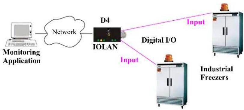
flowchart
graph LR
    A["Monitoring Application"] --> B["Network"]
    B --> C["IOLAN"]
    C --> D["Digital I/O"]
    D --> E["Industrial Freezers"]
    C --> F["Input"]
    D --> G["Input"]
Field Descriptions
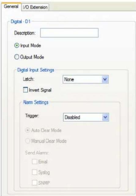
text_image
General I/O Extension Digital - D1 Description: Input Mode Output Mode Digital Input Settings Latch: None Invert Signal Alarm Settings Trigger: Disabled Auto Clear Mode Manual Clear Mode Send Alarms: Email Syslog SNMPConfigure the following parameters:
Description Provide a description of the channel, making it easier to identify.
Data Options: Maximum 20 characters, including spaces
Input Mode When selected, the channel will be reading the status of the line (input). The internal jumpers must match the software configuration; the internal jumpers are factory configured for Input Mode.
Default: Input Mode
Latch Latches (remembers) the activity transition (active to inactive or inactive to active).
Data Options: None, Inactive-to-Active, Active-to-Inactive
Default: None
Invert Signal When enabled, inverts the actual condition of the I/O signal in the status; therefore, an inactive status will be displayed as active.
Default: Disabled
Trigger When the trigger condition is met, triggers the specified alarm action.
Data Options:
- Disabled—No alarm settings. This is the default.
- Inactive—When the expected Digital input is active, going inactive will trigger an alarm.
• Active—When the expected Digital input is inactive, going active will trigger an alarm.
Default: Disabled
| Auto Clear Mode | When enabled, automatically clears the alarm when the trigger condition changes; for example, if the Trigger is Inactive and the alarm is triggered, once the input becomes active again, the alarm will automatically be clearedDefault: Enabled |
| Manual Clear Mode | When enabled, a triggered alarm must be manually cleared.Default: Disabled |
| When enabled, sends an email alert to an email account(s) set up in the System settings when an alarm is triggered or cleared. The email alert data includes the severity level and the value that caused the alarm to trigger or clear. The Email Alert is associated with Level Critical.Default: Disabled | |
| Syslog | When enabled, sends a message to syslog when an alarm is triggered or cleared. The syslog entry includes the severity level and the value that caused the alarm to trigger or clear. The syslog message is associated with Level Critical.Default: Disabled |
| SNMP | When enabled, sends an SNMP trap when an alarm is triggered or cleared. The trap consists of the severity level and whether the alarm was triggered or cleared.Default: Disabled |
Digital Output
Overview
When the channel is set for digital output, either voltage is applied to the channel or the channel is grounded. Note that the internal jumpers must match the software setting and must be set to Output (by default, they are set to Input); see Digital I/O Module on page 431 to find out how to set the internal jumpers.
Functionality
The Digital output channels support three types of Digital output: sink (voltage), source (ground), and sink and source (apply voltage or ground). For the output type, you can configure the following options:
- You can choose to manually activate/deactivate the Digital output.
- You can choose to manually activate/deactivate the Digital output and then specify that the Digital output will either pulse (you get to specify the active and inactive pulse times) continuously or for a specified number of pulse counts.
- You can choose to manually activate/deactivate the Digital output and then specify a delay before the output goes from inactive to active or active to inactive.
- You can also specify a failsafe action that can either activate or inactivate the Digital output when the failsafe timer is triggered (see Failsafe Timer Functionality on page 181 for more information).
In an industrial freezer warehouse, the IOLAN D4 is used to monitor the freezer doors. When one of the industrial freezer doors are left open for more than five minutes, the Monitoring Application (using the Perle API) starts the Digital output sink, causing the strobe light on top of the offending freezer to activate.

flowchart
graph LR
    A["Monitoring Application"] --> B["Network"]
    B --> C["IOLAN"]
    C --> D["Output"]
    C --> E["Input"]
    C --> F["Digital I/O"]
    F --> G["Industrial Freezers"]
Field Descriptions
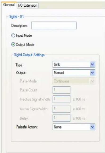
text_image
General I/O Extension Digital - D1 Description: Input Mode Output Mode Digital Output Settings Type: Sink Output: Manual Pulse Mode: Continuous Pulse Count: 1 Inactive Signal Width: 1 x 100 ms Active Signal Width: 1 x 100 ms Delay: 1 x 100 ms Failsafe Action: NoneConfigure the following parameters:
Description Provide a description of the channel, making it easier to identify.
Data Options: Maximum 20 characters, including spaces
Output Mode
When selected, the channel will drive the line (output). The internal jumpers must match the software configuration, so if you change this setting to Output Mode, you will have to also change the internal hardware jumpers.
Default: Disabled
Type Specify the type of digital output.
Data Options:
- Sink—Specifies that the channel will be grounded when active.
- Source—Specifies that the channel will provide voltage when active.
- Sink and Source—Specifies that channel will be grounded when it is inactive and will provide voltage when it is active.
Default: Sink
Output Specify how the channel output will be handled.
Data Options:
- Manual—You must manually manipulate the channel output.
- Pulse—Activates and deactivates the channel output activity in intervals after it is manually activated.
- Inactive-to-Active Delay—The channel output will remain inactive for the specified time interval after it is manually started.
- Active-to-Inactive Delay—The channel output will go inactive after the specified time interval after it is manually started.
Default: Manual
| Pulse Mode | When Output is set to Pulse, you can specify the manner of the pulse. Data Options:Continuous—Continuously pulses active and inactive.Count—Pulses an active/inactive sequence for the specified number of times.Default: Continuous |
| Pulse Count | The channel output will pulse for the specified number of times; each count consists of an active/inactive sequence.Default: 1 |
| Inactive Signal Width | How long the channel will remain inactive during pulse mode.Range: 1-9999 x 100 msDefault: 1 (100 ms) |
| Active Signal Width | How long the channel will be active during the pulse mode.Range: 1-9999 x 100 msDefault: 1 (100 ms) |
| Delay | When a deactivate command is issued, a delay is implemented before the command is executed.Range: 1-9999 x 100 msDefault: 1 (100 ms) |
| Failsafe Action | When there has been no I/O activity within the specified time (set in the I/O Interfaces, Settings on the Failsafe Timer tab) and the Failsafe Timer is triggered.Data Options:None—The state of the Digital/Relay output remains the same, no change.Activate Output—Activates the channel.Deactivate Output—Deactivates the channel.Default: None |
Relay
Overview
Relay channels can open or close a contact for a higher voltage circuit using a lower level control voltage. The Relay output channels work as a physical on/off switch, and are used to drive higher voltage devices with a lower controlling voltage.
You can configure the following Relay output channel options:
- You can choose to manually activate/deactivate the Relay output.
- You can choose to manually activate/deactivate the Relay output and then specify that the Relay output will either pulse (you get to specify the active and inactive pulse times) continuously or for a specified number of pulse counts.
- You can choose to manually activate/deactivate the Relay output and then specify a delay before the output goes from inactive to active or active to inactive.
- You can also specify a failsafe action that can either active or inactivate the Relay output when the failsafe timer is triggered (see Failsafe Timer Functionality on page 181 for more information).
In an industrial freezer warehouse, the IOLAN A4R2 is used to monitor humidity transducers, which are used to help prevent freezer burn. If the humidity reaches a certain percentage (monitored by an Analog channel) a syslog message is sent to the Monitoring Application, causing the Relay channel to activate an internal freezer dehumidifier. The Relay channel is deactivated when the Analog channel sends a clear syslog message to the Monitoring Application and the Relay channel is deactivated.
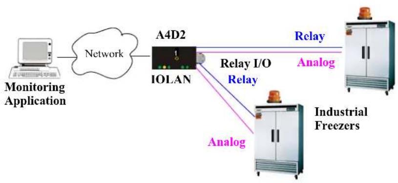
flowchart
graph LR
    A["Monitoring Application"] --> B["Network"]
    B --> C["A4D2 IOLAN"]
    C --> D["Relay I/O Relay"]
    D --> E["Relay"]
    E --> F["Industrial Freezers"]
    C --> G["Analog"]
    D --> H["Analog"]
Field Descriptions
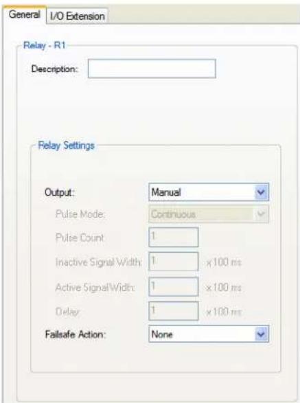
text_image
General I/O Extension Relay - R1 Description: Relay Settings Output: Manual Pulse Mode: Continuous Pulse Count 1 Inactive Signal Width: 1 x 100 ms Active Signal Width: 1 x 100 ms Delay 1 x 100 ms Fallsafe Action: NoneConfigure the following parameters:
Description Provide a description of the channel, making it easier to identify.
Data Options: Maximum 20 characters, including spaces
Output Specify how the channel output will be handled.
Data Options:
• Manual—You must manually manipulate the channel output.
- Pulse—Activates and deactivates the channel output activity in intervals after it is manually activated.
- Inactive-to-Active Delay—The channel output will remain inactive for the specified time interval after it is manually started.
• Active-to-Inactive Delay—The channel output will go inactive after the specified time interval after it is manually started.
Default: Manual
Pulse Mode When Output is set to Pulse, you can specify the manner of the pulse.
Data Options:
• Continuous—Continuously pulses active and inactive.
- Count—Pulses an active/inactive sequence for the specified number of times.
Default: Continuous
Pulse Count The channel output will pulse for the specified number of times; each count consists of an active/inactive sequence.
Default: 1
Inactive Signal How long the channel will remain inactive during pulse mode.
Range: 1-9999 x 100 ms
Default: 1 (100 ms)
| Active Signal Width | How long the channel will be active during the pulse mode. Range: 1-9999 x 100 ms Default: 1 (100 ms) |
| Delay | When a deactivate command is issued, a delay is implemented before the command is executed. Range: 1-9999 x 100 ms Default: 1 (100 ms) |
| Failsafe Action | When there has been no I/O activity within the specified time (set in the I/O Interfaces, Settings on the Failsafe Timer tab) and the Failsafe Timer is triggered. Data Options: None—The state of the Digital/Relay output remains the same, no change. Activate Output—Activates the channel. Deactivate Output—Dactivates the channel. Default: None |
Digital I/O Extension
Overview
The Digital I/O extension feature connects a digital input signal to digital output(s)/relay(s) and/or a TCP/IP application over an IP network. Therefore, when the state of the digital input changes, you can also change the state of the digital output or relay channel or output serial signal pin on a local I/O channel(s), other IOLAN I/O channels, other IOLAN serial signal pins, or the data can be sent to an application(s).
For example, when the door opens (I/O digital input sensor) in a factory, a light goes on in the reception office (remote IOLAN relay channel), and the door open/close is logged by an application on a remote host.
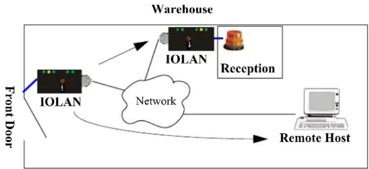
flowchart
graph TD
    A["IOLAN"] --> B["Network"]
    B --> C["Reception"]
    C --> D["Remote Host"]
    E["Front Door"] --> A
    F["Warehouse"] --> C
Functionality
The Digital I/O extension feature requires the digital input to be connected to one or more digital outputs/relays (local or on another IOLAN model), output serial signal pins, and/or TCP/IP applications. In order to create a successful connection between the input and output or application, one side must be must be set to Listen for connection and the other side must be set to Connect to. When the state of an input channel changes, a message is sent to all sessions currently associated with that channel.
When the IOLAN is communicating to an application, there is no need for the output channel or application to respond to messages from the input channel. Each input channel is reported individually, so the receiving application gets the status only at the point at which the channel state has changed.
The message format (from input channel to output channel/application) consists of 20 bytes per status; 10 bytes are currently used and 10 are being reserved for future use.
| Message Type(1 Byte) | Input Number(1 Byte) | IOLAN MACAddress (6 Bytes) | Current AlarmState (1 Byte) | Current Statusof Input (1 Byte) | Reserved(10 Bytes) |
- Message type: (1 Byte)
- 0 = Digital input status
- 1 = Serial I/O status
• Input number: (1 Byte)
- Digital input will be 1, 2, 3, or 4 to represent the channel number
- Serial I/O will be 5 = DSR, 6 = DCD, or 7 = CTS
• MAC Address of the IOLAN sending the input information. (6 Bytes)
• Current Alarm State: (1 Byte)
- 0 = Not in alarm
- 1 = In Alarm
• Current Status of Input: (1 Byte)
- 0 = Inactive for digital input.
• 1 = Active for digital input.
- Reserved for future use. Reserved bytes will have the value 0x00. (10 Bytes)
Applications should be written in such a way so that they look at the Message type byte to determine the format of the message. If the application encounters a Message type it does not recognize, it should discard the message and read the next 20 byte block.
Field Descriptions
The Local connection option is different depending on whether you are configuring a Digital Input or a Digital Output/Relay channel. The Local connection option for Digital Input lists all the local Digital Output channels or output serial signal pins that it is associated with. Digital Input can be connected to multiple local Digital Output or Relay channels or output serial signal pins. However, a Digital Output can only be associated with one Digital Input channel or input serial signal pin. The Local connection option for Digital Output configures the specific local Digital Input channel or input serial signal pin on the same IOLAN that it is to be connected to.
For a description of the SSL/TLS parameters (not available when Local connection is configured), see SSL/TLS Settings Tab Field Descriptions on page 338.
Digital Input/DSR/DCD/CTS Digital Output/Relay/DTR/RTS
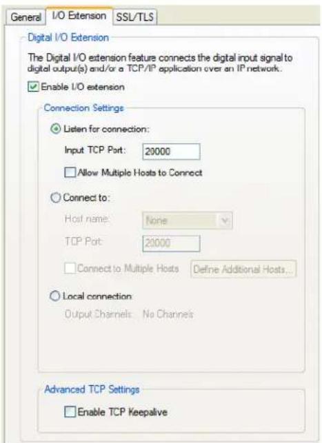
text_image
General I/O Extension SSL/TLS Digital I/O Extension The Digital I/O extension feature connects the digital input signal to digital output(s) and/or a TCP/IP application over an IP network. Enable I/O extension Connection Settings Listen for connection: Input TCP Port: 20000 Allow Multiple Hosts to Connect Connect to: Host name: None TCP Port: 20000 Connect to Multiple Hosts Define Additional Hosts... Local connection Output Channels: No Channels Advanced TCP Settings Enable TCP Keepalive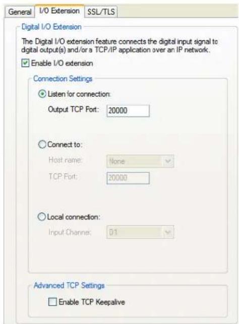
text_image
General I/O Extension SSL/TLS Digital I/O Extension The Digital I/O extension feature connects the digital input signal to digital output(s) and/or a TCP/IP application over an IP network. Enable I/O extension Connection Settings Listen for connection: Output TCP Port: 20000 Connect to: Host name: None TCP Port: 20000 Local connection: Input Channel: 01 Advanced TCP Settings Enable TCP KeepaliveConfigure the following parameters:
Enable I/O extension
When enabled, the digital channel can be connected to:
- A Digital output or relay (if the I/O model supports relay) channel on the same IOLAN
• Output Serial Signal Pins (DTR/RTS) - A Digital output channel on another IOLAN(s) or output serial signal pins (DTR/RTS) on another IOLAN(s)
• A TCP/IP application(s) running on a host on the network
Default: Disabled
Listen for connection
When enabled, the channel/serial signal pin will wait for connections to be initiated by another I/O channel or a TCP/IP application.
Default: Enabled
Input TCP Port
The TCP port that the channel/serial signal pin will use to listen for incoming connections.
Default: 2000 for channel 1, then increments by one for each channel
| Allow Multiple Hosts to Connect | When this option is enabled, multiple I/O channels and/or TCP/IP applications can connect to this channel/serial signal pin.Default: Disabled |
| Connect to | When enabled, the channel/serial signal pin initiates communication to another I/O channel or a TCP/IP application.Default: Enabled |
| Host Name | The configured host or another IOLAN that the I/O channel will connect to.Default: None |
| TCP Port | The TCP Port that the channel/serial signal pin will use to communicate to another IOLAN or a TCP/IP application.Default: 2000 for channel 1, then increments by one for each channel |
| Connect to Multiple Hosts | When enabled, input channel or serial signal pin can communicate to multiple hosts running a TCP/IP application or I/O channels.Default: Disabled |
| Define Additional Hosts Button | Click this button to define the hosts/IOLANs that this channel or serial signal pin will connect to. This button is also used to define the Primary/Backup host functionality. |
| Local connection | When this option is enabled, the input or output, depending on how the channel or serial signal pin is configured, will be associated with another local IOLAN I/O channel or serial signal pin.When the channel is configured as digital input or when configuring an input serial signal pin, the Output Channels parameter displays all the local digital output signals or relays that it is associated with.When the channel is configured as digital output, you must select a local digital input channel or input serial signal pin on the IOLAN.Note that the Failsafe Action is not compatible this option.Default: Disabled |
| Enable TCP Keepalive | Enables a per-connection TCP keepalive feature. After the configured number of seconds, the connection will send a gratuitous ACK to the network peer, thus either ensuring the connection stays active OR causing a dropped connection condition to be recognized.This parameter needs to be used in conjunction with Monitor Connection Status Interval parameter found in the Serial, Advanced, Advanced Settings tab. The interval specifies the inactivity period before "testing" the connection.Default: Disabled |
Adding/Editing Additional Hosts
You can define a list of hosts that the I/O channel will communicate to or a primary/backup host.
Configure the following parameters:
| Define additional hosts to connect to | When this option is enabled, you can define up to 49 hosts/IOLANs that the I/O channel or serial signal pin will attempt communicate to. With this mode of operation, the I/O channel will connect to multiple hosts/IOLANs simultaneously.Default: Enabled |
| Add Button | Click the Add button to add a host to the list of hosts that will be receiving communication from the I/O channel or serial signal pin. |
| Edit Button | Highlight an existing host and click the Edit button to edit a host in the list of hosts that will be receiving communication from the I/O channel. |
| Delete Button | Click the Delete button to delete a host to the list of hosts that will be receiving communication from the I/O channel or serial signal pin. |
| Define a primary host and backup... | When this option is enabled, you need to define a primary host that the I/O channel will communicate to and a backup host, in the event that the I/O channel loses communication to the primary host. The I/O channel will first establish a connection to the primary host. Should the connection to the primary host be lost (or never established), the I/O channel will establish a connection the backup host. Once connected to the backup, the I/O channel will attempt to re-establish a connection to the Primary host, once this is successfully done, it gracefully shuts down the backup connection.Default: Disabled |
| Primary Host | Specify a preconfigured host that the I/O channel or serial signal pin will communicate to.Default: None |
| TCP Port | Specify the TCP port that the I/O channel or serial signal pin will use to communicate to the Primary Host.Default: 2000 for channel 1, then increments by one for each channel |
| Backup Host | Specify a preconfigured host that the I/O channel or serial signal pin will communicate to if the I/O channel cannot communicate with the Primary Host.Default: None |
| TCP Port | Specify the TCP port that the channel or serial signal pin will use to communicate to the Backup Host.Default: 0 |
Adding/Editing a Multihost Entry
When you click the Add or Edit button, the Host Entry window appears. The hosts in the multihost list must already be defined (see Host Table on page 111 to learn how to create a host). If you add a host that was defined with its fully qualified domain name (FQDN), it must be resolvable by your configured DNS server.
Configure the following parameters:
Host Name Specify the preconfigured host that will be in the multihost list.
Default: None
TCP Port
Specify the TCP port that the I/O channel or serial signal pin will use to communicate to the Host.
Default: 0
Temperature
Temperature input channels monitor RTD or thermocouple temperature sensors inputs for the most common ranges. You can also configure severity alarms that can send an email, a syslog message, and/or an SNMP trap when an alarm is triggered or cleared; See Alarm Settings on page 203 for more information about the alarms.
RTD ranges are:
| Pt100 a=385 -50 to 150C | Pt100 a=392 -50 to 150C | Pt1000 a=385 -40 to 160C |
| Pt100 a=385 0 to 100C | Pt100 a=392 0 to 100C | NiFe604 a=518 -80 to 100C |
| Pt100 a=385 0 to 200C | Pt100 a=392 0 to 200C | NiFc604 a=518 0 to 100C |
| Pt100 a=385 0 to 400C | Pt100 a=392 0 to 400C | |
| Pt100 a=385 -200 to 200C | Pt100 a=392 -200 to 200C |
IEC RTD 100 ohms.=0.00385
JIS RTD 100 ohms.=0.00392
Thermocouple ranges are:
| B 500 to 1800C | K 0 to 1370C | T -100 to 400C |
| E 0 to 1000C | R 500 to 1750C | |
| J 0 to 760C | S 500 to 1750C |
In the following example, a Temperature I/O IOLAN is used to monitor industrial freezer temperature sensors, with an alarm set to send a syslog message if the temperature rises above 31^ C.
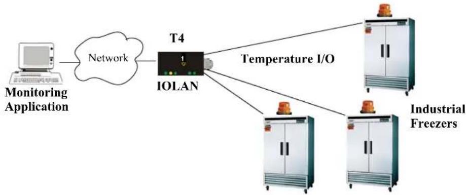
flowchart
graph TD
    A["Monitoring Application"] -->|Network| B["IOLAN"]
    B --> C["Temperature I/O"]
    B --> D["Industrial Freezers"]
    B --> E["Industrial Freezers"]
Field Descriptions
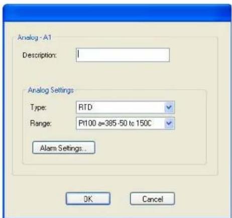
text_image
Analog -A1 Description: Analog Settings Type: RTD Range: Pt100 e=385-50 to 150C Alarm Settings... OK CancelConfigure the following parameters:
Description Provide a description of the channel, making it easier to identify.
Data Options: Maximum 20 characters, including spaces
Type Specify the type of sensor you are using to measure temperature.
Data Options: RTD, Thermocouple
Default: RTD
Range Specify the temperature range that you want to measure.
Data Options:
- RTD—Pt100 a=385 -50 to 150C, Pt100 a=385 0 to 100C, Pt100 a=385 0 to 200C, Pt100 a=385 0 to 400C, Pt100 a=385 -200 to 200C, Pt100 a=392 -50 to 150C, Pt100 a=392 0 to 100C, Pt100 a=392 0 to 200C, Pt100 a=392 0 to 400C, Pt100 a=392 -200 to 200C, Pt1000 a=385 -40 to 160C, NiFe604 a=518 -80 to 100C, NiFe604 a=518 0 to 100C
- Thermocouple—B 500 to 1800C, E 0 to 1000C, J 0 to 760C, K 0 to 1370C, R 500 to 1750C, S 500 to 1750C, T -100 to 400C
Default: RTD is Pt100 a=385 -50 to 150C. Thermocouple is J 0 to 760C.
Alarm Settings Button Click the Alarm Settings button to specify the trigger and clear levels for the alarms. Notice that the Analog Alarm Settings window has two alarm configuration views, a basic alarm view and an advanced alarm view.
See Alarm Settings on page 203 for field descriptions.
Alarm Settings
Analog and Temperature input models support an Alarm mechanism in which you can specify up to five severity levels of alarm triggers and clear levels; the alarm triggers/clear levels can activate in either increasing or decreasing severity levels.
Each time an alarm is triggered or cleared, you can specify any combination of the following to be initiated:
- An SNMP trap
• An email message
• A message to syslog
Basic Analog Alarm Settings
The basic Analog Alarm Settings window allows you to configure one severity alarm, whereas the advanced window allows you to configure up to five severity alarm levels.
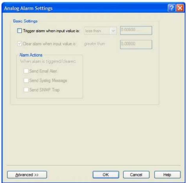
text_image
Analog Alarm Settings Basic Settings Trigger alarm when input value is: less than 0.00000 Clear alarm when input value is: greater than 0.00000 Alarm Actions When alarm is triggered/cleaned: Send Email Alert Send Syralg Message Send SNMP Trap Advanced >> OK Cancel HelpConfigure the following parameters:
Trigger alarm when specify the value that will trigger an alarm, the measurement is based on the input value is Type and Range that you specify. This value must not fall within the scope of the value used to clear an alarm.
Clear alarm when input value is Specify that value that will clear an alarm, the measurement is based on the Type and Range that you specify. This value must not fall within the scope of the value used to trigger an alarm.
Send Email Alert When enabled, sends an email alert to an email account(s) set up in the System settings when an alarm is triggered or cleared. The email alert data includes the severity level and the value that caused the alarm to trigger or clear. The Email Alert is associated with Level Critical.
Default: Disabled
Send Syslog Alert
When enabled, sends a message to syslog when an alarm is triggered or cleared. The syslog entry includes the severity level and the value that caused the alarm to trigger or clear. The syslog message is associated with Level Critical.
Default: Disabled
Send SNMP Alert
When enabled, sends an SNMP trap when an alarm is triggered or cleared. The trap consists of the severity level and whether the alarm was triggered or cleared.
Default: Disabled
Advanced Analog Alarm Settings
The advanced Analog Alarm Settings window expands the basic alarm settings options to up to five severity levels.
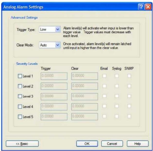
text_image
Analog Alarm Settings Advanced Settings Trigger Type: Low Clear Mode: Auto Alarm level(s) will activate when input is lower than trigger value. Trigger values must decrease with each level. Once activated, alarm level(s) will remain latched until input is higher than the clear value. Severity Levels Trigger Clear Email SyslogSNMP Level 1 0.00000 0.00000 Level 2 0.00000 0.00000 Level 3 0.00000 0.00000 Level 4 0.00000 0.00000 Level 5 0.00000 0.00000 << Basic OK Cancel HelpConfigure the following parameters:
Trigger Type
If the Trigger Type is Low, an alarm is triggered when the input drops below the specified Trigger value; other severity level trigger values must decrease in value with each subsequent level. If the Trigger Type is High, an alarm is triggered when the input is higher than the specified Trigger value; other severity level trigger values must increase in value with each subsequent level.
Clear Mode
To clear an alarm, the input must drop below the specified value when Trigger Type is High or go above the specified value when Trigger Type is Low.
Level 1-5
Defines the Level severity settings for up to five levels. If the Trigger Type is Low, an alarm is triggered when the input drops below the specified Trigger value; other severity level trigger values must decrease in value with each subsequent level. If the Trigger Type is High, an alarm is triggered when the input is higher than the specified Trigger value; other severity level trigger values must increase in value with each subsequent level.
| Trigger | If the Trigger Type is Low, an alarm is triggered when the input drops below the specified Trigger value; other severity level trigger values must decrease in value with each subsequent level. If the Trigger Type is High, an alarm is triggered when the input is higher than the specified Trigger value; other severity level trigger values must increase in value with each subsequent level. |
| Clear | To clear an alarm, the input must drop below the specified value when Trigger Type is High or go above the specified value when Trigger Type is Low. |
| When enabled, sends an email alert to an email account(s) set up in the System settings when an alarm is triggered or cleared. The email alert data includes the severity level and the value that caused the alarm to trigger or clear. The Email Alert is associated with Level Critical.Default: Disabled | |
| Syslog | When enabled, sends a message to syslog when an alarm is triggered or cleared. The syslog entry includes the severity level and the value that caused the alarm to trigger or clear. The syslog message is associated with Level Critical.Default: Disabled |
| SNMP | When enabled, sends an SNMP trap when an alarm is triggered or cleared. The trap consists of the severity level and whether the alarm was triggered or cleared.Default: Disabled |
I/O UDP
Industrial applications often monitor the status of I/O devices such as sensors, alarms, relays, etc. by polling for I/O data. The IOLAN's I/O UDP feature can help to minimize network traffic by broadcasting I/O status to industrial applications on specified intervals, providing I/O status in a timely manner.
The IOLAN's I/O UDP broadcast feature sends the status of attached I/O devices to defined hosts on the network. Depending upon the IOLAN model and the configuration of the I/O channels, the UDP packet contains the current status and/or data of each enabled I/O channel or serial pin signal.
UDP Unicast Format
PC applications must be able to interpret the UDP packet to obtain I/O channel status and data. This section provides the detailed structure of the UDP datagram and its data format.
UDP Broadcast Packet
| Version(1 Byte) | Total Packet Length(2 Bytes) | Analog Section | Digital/Relay Section | Serial Pin Signal Section |
Each section, with the exceptions of the Version and Total Packet Length sections, is comprised of its own subset of bytes.
Note: All 2 byte values are in big Endian (network) order. All 4 byte values are IEEE 754 single precision floating point numbers in big Endian (network) order.
- Version—The current version of the format of I/O UDP broadcast packet.
• Total Packet Length—The total length of the UDP packet. - Analog Section—The Analog Section of the UDP packet, which contains data/status of the Analog I/O channels. The Analog Channel Data subsection (within the Analog Section) will only exist if the channel(s) is enabled.
- Digital/Relay Section—The Digital/Relay Section of the UDP packet, which contains status of Digital and Relay I/O channels. The Channel Data subsection within the Digital/Relay Section will always be present.
- Serial Pin Signal Section—The Serial Pin Signal Section of the UDP packet, which contains the status of the IOLAN's serial port's control signal pins. The Serial Pin Signal Data subsection within the Serial Signal Pins Section will always be present.
Analog Section
The Analog Section of the UDP packet is comprised of I/O data for each enabled Analog channel.
If the IOLAN I/O model does not support Analog channels, the Analog Channel Data subsection of the Analog Section will NOT be present in the UDP packet.
| Section Length | Channel Enabled | Analog Channel Data (for each enabled channel) | |||||
| 2 Bytes | Byte curRaw | Value2 Bytes | minRawValue2 Bytes | maxRawValue2 Bytes | curEngValue4 Bytes | minEngValue4 Bytes | maxEngValue4 Bytes |
- Section Length—The total length of the Analog section (this value will vary, the field length is 2 Bytes). This value will vary because it will contain one Analog Channel Data subsection (18 bytes) for each Analog channel that is enabled.
- Channel Enabled—The Channel Enabled field is 1 byte in least significant bit order, for each channel. If the channel is enabled, the bit is set to 1. If the channel is disabled, the bit is set to 0 (zero).
| Channel Enabled (1 Byte, one bit for each channel) | |||||||
| Channel 4 | Channel 3 | Channel 2 C | Channel 1 | ||||
- Analog Channel Data—Consists of Analog Channel Data for each enabled Analog channel on the IOLAN. If an Analog channel is disabled, there is no data for that channel. Therefore, the Analog Section will contain the Section Length value, the Channel Enabled value, and 18 bytes of I/O data for each enabled Analog channel. For example, an IOLAN I/O model with four Analog channels that has only three of those Analog channels enabled will contain 54 bytes of Analog Channel Data (18 bytes * 3 Analog channels).
The following values make up the Analog Channel Data for each enabled Analog channel:
- curRawValue—The current raw value received by the channel.
- minRawValue—The minimum raw value received by the channel until it is cleared.
- maxRawValue—The maximum raw value received from the channel until it is cleared.
- curEngValue—The current raw value that has been converted to voltage/current for Analog or Celsius/Fahrenheit for Temperature.
- minEngValue—The minimum raw value that has been converted to voltage/current for Analog or Celsius/Fahrenheit for Temperature until it is cleared.
- maxEngValue—The maximum raw value that has been converted to voltage/current for Analog or Celsius/Fahrenheit for Temperature until it is cleared.
Digital/Relay Section
The Digital/Relay Section of the UDP packet provides the status of Digital and Relay channels. The data for the status of each channel is represented by 1 byte, with each bit representing a channel (least significant bit format).
The Digital/Relay Channel Data subsection is present in the UDP packet regardless of whether or not the IOLAN model supports Digital/Relay channels.
| Length | Channel Enabled | Digital/Relay Channel Data (1 Byte, one bit for each channel) | |||||||
| 2 Bytes 1 | Byte Channel | 4 Channel | 3 Channel | 2 Channel | 1 | ||||
- Length—The length of Digital/Relay Section within the UDP packet (this value will always be 2 Bytes).
- Channel Enabled—This is based on the configuration of the Digital/Relay channels. The Channel Enabled field is 1 byte in least significant bit order, for each channel. If the channel is enabled, the bit is set to 1. If the channel is disabled, the bit is set to 0 (zero).
| Channel Enabled (1 Byte, one bit for each channel) | ||||||
| Channel 4 | Channel 3 | Channel 2 C channel 1 | ||||
- Digital/Relay Channel Data—Each bit represents a channel status, 1 for on or 0 for off (unless the channel has been configured to be inverted, in which case 0 is on and 1 if off).
Serial Pin Signal Section
The Serial Pin Signal Section of the UDP packet provides the status of the serial pin signals from the IOLAN's serial port. Each serial pin signal (DSR, DTR, CTS, etc.) is mapped to a bit in the 1-byte data section.
The Serial Pin Signal Data subsection is present in the UDP packet regardless of whether or not the serial port is configured for the Control I/O profile or the serial pin signals are enabled.
| Length | Pin Enabled | Serial Pin Signal Data (1 Byte, one bit for each signal) | |||||||
| 2 Bytes 1 | Byte RTS DTR CTS DCD DSR | ||||||||
- Length—The total length of the Serial Pin Signal Data (this value will always be 2 Bytes).
- Pin Enabled—This based upon the configuration of the signal pins on the serial port. When the serial port profile is set to Control I/O and a serial pin signal(s) is enabled, the bit is set to 1. For any serial pin signals that are disabled, the bit is set to 0 (zero) and any data associated with those serial pin signals should be ignored.
| Pin Enabled (1 Byte, one bit for each serial pin signal) | |||||||
| RTS | DTR | CTS DCD | DSR | ||||
- Serial Pin Signal Data—1 byte with each bit being set to high (1) or low (0) for the appropriate serial pin signals.
UDP Unicast Example
For an example of the I/O UDP unicast, see the sample program, ioudpbcast.c, found on your CD-ROM.
I/O Modbus Slave
If you have a Modbus serial or TCP application, it can access I/O connected to the IOLAN when the I/O Global Modbus Slave is enabled. You must supply a unique UID for the IOLAN, as it will act as a Modbus Slave.
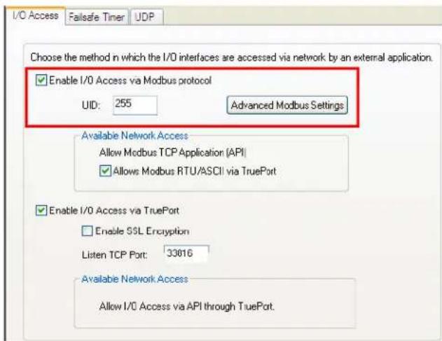
text_image
I/O Access Failsafe Timer UDP Choose the method in which the I/O interfaces are accessed via network by an external application. Enable I/O Access via Modbus protocol UID: 255 Advanced Modbus Settings Available Network Access Allow Modbus TCP Application [API] Allows Modbus RTU/ASCII via TruePort Enable I/O Access via TruePort Enable SSL Encryption Listen TCP Port: 33016 Available Network Access Allow I/O Access via API through TruePort.There are three ways your Modbus Application can connect to the IOLAN to access I/O.
Modbus Serial Application Connected to the Serial Port
Your Modbus serial application can be connected right to the IOLAN serial port to access I/O.
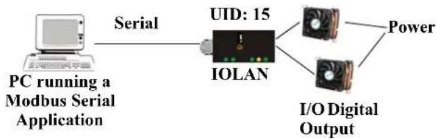
flowchart
graph LR
    A["PC running a Modbus Serial Application"] -->|Serial| B["IOLAN"]
    B --> C["Power"]
    B --> D["I/O Digital Output"]
    B --> E["UD: 15"]
Modbus Serial Application Connected to the Network
If you want to access the I/O from a LAN connection, you can install TruePort on the PC running the Modbus serial application as described in TruePort I/O on page 215 and connect to the IOLAN over the network.
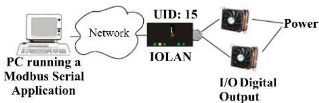
flowchart
graph LR
    A["PC running a Modbus Serial Application"] --> B["Network"]
    B --> C["IOLAN"]
    C --> D["I/O Digital Output"]
    C --> E["Power"]
    C --> F["15"]
Modbus TCP Application
If you have a Modbus RTU or Modbus ASCII program, you can access the I/O by connecting to the IOLAN over the network.
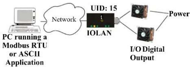
The section defines the function codes and registers you will need to access the I/O through Modbus TCP, Modbus serial, or Modbus serial/TruePort.
Function Codes
The following function codes are supported by the IOLAN:
- 01 read coils
• 03 read multiple holding registers
• 04 read input registers - 05 write coil
• 06 write single register
• 08 diagnostics (echo the request)
• 15 force multiple coils
• 16 write multiple registers
There are four Modbus data models:
| Discrete Input Not used | |
| Coils Digital Input (DI), Alarm state for DI, Digital Output (DO). All coils are Boolean values and are 1 byte. | |
| Input Registers (IR) | Analog Input (AI), Alarm state for AI. All Input Registers are 2 bytes long. |
| Holding Registers Status (R), Control value (R/W or W). Holding Registers with _ENG registers are 4 bytes long, all other Holding Registers are 2 bytes long. | |
All coil/register values are in decimal.
I/O Coil/Register Descriptions
This section contains descriptions of I/O coils:
- MB_REG_DI_SENSOR—Status of Digital input. 1 is Active, 0 is Inactive. If Invert Signal is configured on, 0 is Active, 1 is Inactive. If input is Latched, returns latched status.
- MB_REG_DI_SENSOR_ALARM_STATE—Indication if input is in alarm state. 1 is In Alarm state, 0 is Not in Alarm state. A write of any value clears the alarm state.
- MB_REG_DO_SENSOR—Status of Digital output. 1 is Active, 0 is Inactive. If Invert Signal is configured on, 0 is Active, 1 is Inactive.
This section contains descriptions of I/O holding registers:
- MB_REG_HR_DI_SENSOR_LATCH—The latch status of the Digital input. 1 is Latched, 0 is Not latched. A write of any value will clear the latch.
- MB_REG_HR_DO_SENSOR_PULSE_ISW—Inactive Signal Width. This is how long the channel will remain inactive during pulse mode in increments of 100ms. Valid values are 1-9999. The default is 1 (100 ms).
- MB_REG_HR_DO_SENSOR_PULSE_ASW—Active Signal Width. This is how long the channel will be active during the pulse mode in increments of 100ms. Valid values are 1-9999. The default is 1 (100 ms).
- MB_REG_HR_DO_SENSOR_PULSE_COUNT—The number of times the channel output will pulse. Each count consists of an active/inactive sequence. The default is 1 cycle.
- MB_REG_HR_AI_CLEAR_ALARM_LATCH—Used to reset a latched alarm state. A write of any value will clear the alarm latch for the specific Analog input.
- MB_REG_HR_AI_CLEAR_MAX—Used to reset the Analog input maximum value reached. A write of any value will reset the maximum.
- MB_REG_HR_AI_CLEAR_MIN—Used to reset the Analog input minimum value reached. A write of any value will reset the minimum.
This section contains descriptions of I/O input registers:
- MB_REG_IR_CURR_ENG—The current value of an Analog or Temperature input converted to appropriate units. For Analog, this will be in voltage or current, depending on the configuration. For the Temperature, this value will be in Celsius or Fahrenheit, depending on configuration.
- MB_REG_IR_MIN_ENG—The minimum converted value ever reached on this input since the IOLAN was re-started or a manual clear was issued.
- MB_REG_IR_MAX_ENG—The maximum converted value ever reached on this input since the IOLAN was re-started or a manual clear was issued.
- MB_REG_IR_CURR_RAW—The current raw value received from the Analog to Digital converter. This is a hexadecimal value in the range of 0 -0xFFFF.
- MB_REG_IR_MIN_RAW—The minimum raw value ever reached on this input since the IOLAN was re-started or a manual clear was issued.
- MB_REG_IR_MAX_RAW—The maximum converted value ever reached on this input since the IOLAN was re-started or a manual clear was issued.
- MB_REG_IR_ALARM_LEVEL—This gives the current alarm severity level for the corresponding Analog input. Severity levels range from 0 (not in alarm) to 5 (highest alarm severity).
Serial Port Coil/Register Descriptions
This section contains descriptions of serial port coils:
- MB_REG_DI_DSR—The status of the DSR input signal. 1 is Active, 0 is Inactive. If Invert Signal is configured on, 0 is Active, 1 is Inactive. If input is Latched, returns latched status.
- MB_REG_DI_DSR_ALARM_STATE—The alarm state of DSR input signal. 1 is In Alarm state, 0 is Not in Alarm state. A write of any value clears the alarm state.
- MB_REG_DI_DCD—The status of DCD line. 1 is Active, 0 is Inactive. If Invert Signal is configured on, 0 is Active, 1 is Inactive.
- MB_REG_DI_DCD_ALARM_STATE—The alarm state of DCD input signal. 1 is in Alarm state, 0 is Not in Alarm state. A write of any value clears the alarm state.
- MB_REG_DI_CTS—The status of CTS input signal. 1 is Active, 0 is Inactive. If Invert Signal is configured on, 0 is Active, 1 is Inactive.
- MB_REG_DI_CTS_ALARM_STATE—The alarm state of CTS input signal. 1 is Alarm, 0 is Not in Alarm. A write of any value clears the alarm state.
- MB_REG_DO_DTR—The status of DTR output signal. 1 is Active, 0 is Inactive.
- MB_REG_DO_RTS—The status of RTS output signal. 1 is Active, 0 is Inactive.
This section contains descriptions of serial port holding registers:
- MB_REG_HR_DI_DSR_LATCH—The latched status for the DSR signal. 1 is Latched, 0 is Not Latched. A write any value will clear the latch.
- MB_REG_HR_DI_DCD_LATCH—The latched status for the DCD signal. 1 is Latched, 0 is Not Latched. A write any value will clear the latch.
- MB_REG_HR_DI_CTS_LATCH—The latched status for the CTS signal. 1 is Latched, 0 is Not Latched. A write any value will clear the latch.
A4/T4 Registers
The following registers are supported by the IOLAN A4 and T4 Input models:
| Data Model A1/T1 A2/T2 A3/T3 A4/T4 R/W | ||||||
| Holding Registers: | ||||||
| MB_REG_HR_AI_CLEAR_ALARM_LATCH 20 | 049 2050 20 | 051 2052 W | ||||
| MB_REG_HR_AI_CLEAR_MAX 2113 2114 21 | 5 2116 W | |||||
| MB_REG_HR_AI_CLEAR_MIN | 2177 2178 | 2179 2180 | W | |||
| Input Registers: | ||||||
| MB_REG_IR_CURR_ENG | 2080 2112 | 2144 2176 | R | |||
| MB_REG_IR_MIN_ENG | 2082 2114 | 2146 2178 | R | |||
| MB_REG_IR_MAX_ENG | 2084 2116 | 2148 2180 | R | |||
| MB_REG_IR_CURR_RAW | 2086 2118 | 2150 2182 | R | |||
| MB_REG_IR_MIN_RAW | 2087 2119 | 2151 2183 | R | |||
| MB_REG_IR_MAX_RAW | 2088 2120 | 2152 2184 | R | |||
| MB_REG_IR_ALARM_LEVEL | 2089 2121 | 2153 2185 | R | |||
A4D2/A4R2 Registers
The following coils and registers are supported by the IOLAN A4D2 and A4R2 I/O models:
| Data Model | A1 | A2 | A3 | A4 | D1/R1 | D2/R2 | R/W | |
| Coils: | ||||||||
| MB_REG_DI_SENSOR ---- ---- ---- 6149 | 6150 R | |||||||
| * | MB_REG_DI_SENSOR_ALARM_STATE ---- | ---- ---- | ---- 62 | 13 621 | 4 R/W | |||
| MB_REG_DO_SENSOR ---- ---- ---- 6661 | 6662 R/W | |||||||
| Holding Registers: | ||||||||
| MB_REG_HR_DI_SENSOR_LATCH | ---- ---- | ---- ---- | ---- 61 | 49 6150 | R/W | |||
| MB_REG_HR_DO_SENSOR_PULSE_ISW | ---- ---- | ---- ---- | ---- 62 | 13 6214 | R/W | |||
| MB_REG_HR_DO_SENSOR_PULSE_ASW | ---- ---- | ---- ---- | ---- 627 | 7 6278 | R/W | |||
| MB_REG_HR_DO_SENSOR_PULSE_COUNT | ---- ---- | ---- ---- | ---- 634 | 1 6342 | R/W | |||
| MB_REG_HR_AI_CLEAR_ALARM_LATCH | 2049 | 2050 | 2051 | 2052 | ---- | ---- | W | |
| MB_REG_HR_AI_CLEAR_MAX | 2113 | 2114 | 2115 | 2116 | ---- | ---- | W | |
| MB_REG_HR_AI_CLEAR_MIN | 2177 | 2178 | 2179 | 2180 | ---- | ---- | W | |
| Input Registers: | ||||||||
| MB_REG_IR_CURR_ENG | 2080 | 2112 | 2144 | 2176 | ---- | ---- | R | |
| MB_REG_IR_MIN_ENG | 2082 | 2114 | 2146 | 2178 | ---- | ---- | R | |
| MB_REG_IR_MAX_ENG | 2084 | 2116 | 2148 | 2180 | ---- | ---- | R | |
| MB_REG_IR_CURR_RAW | 2086 | 2118 | 2150 | 2182 | ---- | ---- | R | |
| MB_REG_IR_MIN_RAW | 2087 | 2119 | 2151 | 2183 | ---- | ---- | R | |
| MB_REG_IR_MAX_RAW | 2088 | 2120 | 2152 | 2184 | ---- | ---- | R | |
| MB_REG_IR_ALARM_LEVEL | 2089 | 2121 | 2153 | 2185 | ---- | ---- | R | |
*For DI alarm state, read will get state, write will clear alarm.
D4/D2R2 Registers
The following coils and registers are supported by the IOLAN D4 and D2R2 I/O models:
| Data Model | D1 | D2 | D3/R1 | D4/R2 | R/W | |
| Coils: | ||||||
| MB_REG_DI_SENSOR 6145 6146 6147 6148 R | ||||||
| * | MB_REG_DI_SENSOR_ALARM_STATE 6209 | 6210 6211 | 6212 R/W | |||
| MB_REG_DO_SENSOR | 6657 6658 | 6659 6660 R/W | ||||
| Holding Registers: | ||||||
| MB_REG_HR_DI_SENSOR_LATCH | 6145 6146 | 6147 6148 R/W | ||||
| MB_REG_HR_DO_SENSOR_PULSE_ISW | 6209 6210 | 6211 6212 R/W | ||||
| MB_REG_HR_DO_SENSOR_PULSE_ASW | 6273 6274 | 6275 6276 R/W | ||||
| MB_REG_HR_DO_SENSOR_PULSE_COUNT | 6337 6338 | 6339 6340 R/W | ||||
*For DI alarm state, read will get state, write will clear alarm.
Serial Pin Signals
The following coils and registers are supported by the IOLAN I/O models:
| Data Model Pin R/W | |||
| Coils: | |||
| MB_REG_DI_DSR | 4225 | R | |
| MB_REG_DI_DSR_ALARM_STATE | 4289 | R/W | |
| MB_REG_DI_DCD | 4353 | R | |
| MB_REG_DI_DCD_ALARM_STATE | 4417 | R/W | |
| MB_REG_DI_CTS | 4481 | R | |
| MB_REG_DI_CTS_ALARM_STATE | 4545 | R/W | |
| MB_REG_DO_DTR | 4673 | R/W | |
| MB_REG_DO_RTS | 4737 | R/W | |
| Holding Registers: | |||
| MB_REG_HR_DI_DSR_LATCH | 4097 | R/W | |
| MB_REG_HR_DI_DCD_LATCH | 4609 | R/W | |
| MB_REG_HR_DI_CTS_LATCH | 5121 | R/W | |
TruePort I/O
You can see a sample API I/O over TruePort program called ioapiotp.c on the CD-ROM.
TruePort/Modbus Combination
If you have a Modbus serial application running on a PC that is connected to a network, you can use TruePort as a virtual serial connection to communicate with the IOLAN over the network to access I/O data. You also have the option of enabling SSL as a security option to encrypt the data that is communicated between the IOLAN and the host machine (SSL/TLS must be configured in the Server settings and on the TruePort host).
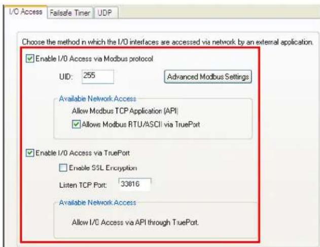
text_image
I/O Access Failsafe Timer UDP Choose the method in which the I/O interfaces are accessed via network by an external application. Enable I/O Access via Modbus protocol UID: 255 Advanced Modbus Settings Available Network Access Allow Modbus TCP Application (API) Allows Modbus RTU/ASCII via TruePort Enable I/O Access via TruePort Enable SSL Encryption Listen TCP Port: 33016 Available Network Access Allow I/O Access via API through TruePort.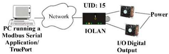
flowchart
graph LR
    A["PC running a Modbus Serial Application/TruePort"] --> B["Network"]
    B --> C["IOLAN"]
    C --> D["I/O Digital Output"]
    C --> E["Power"]
    C --> F["UID: 15"]
The host running TruePort must be in Modbus/ASCII or Modbus/RTU mode.
API Over TruePort Only
If you have a custom application that talks to a serial port, you can use TruePort as a virtual serial port to communicate with the IOLAN over the network to access I/O data using the Perle API. You also have the option of enabling SSL as a security option to encrypt the data that is communicated between the IOLAN and the host machine (SSL/TLS must be configured in the Server settings and on the TruePort host). See Accessing I/O Data Via TruePort on page 217 for more information on the API.)
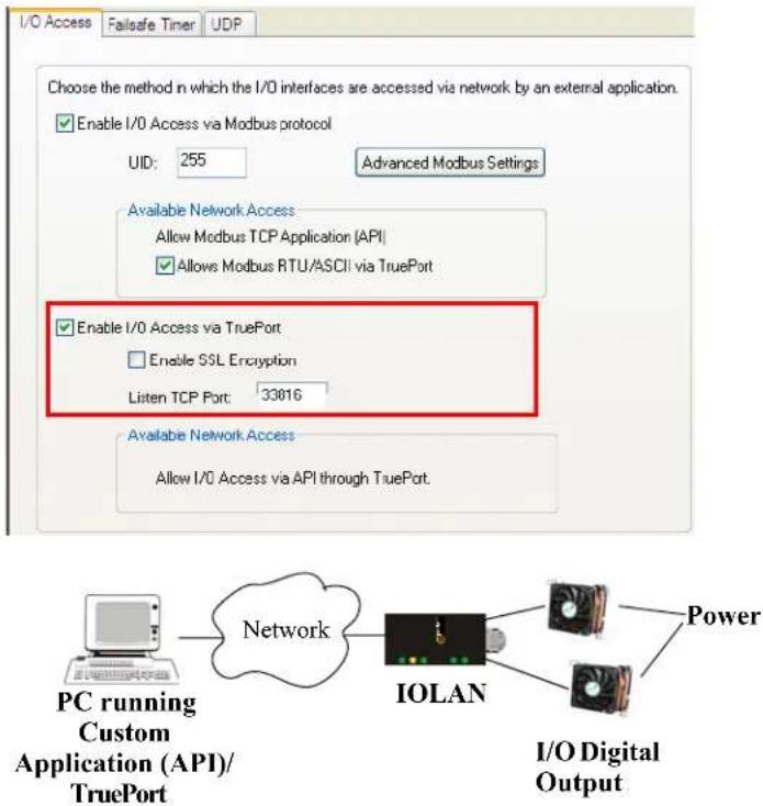
text_image
I/O Access Failsafe Timer UDP Choose the method in which the I/O interfaces are accessed via network by an external application. Enable I/O Access via Modbus protocol UID: 255 Advanced Modbus Settings Available Network Access Allow Modbus TCP Application (API) Allows Modbus RTU/ASCII via TruePort Enable I/O Access via TruePort Enable SSL Encryption Listen TCP Port: 33816 Available Network Access Allow I/O Access via API through TruePort. PC running Custom Application (API)/TruePort Network IOLAN Power I/O Digital OutputThe host running TruePort must be in I/O API mode.
Accessing I/O Data Via TruePort
Introduction
Analog and Digital I/O data, as well as output control, can be accessed in several ways. To have access from an application running on a workstation or server, the I/O Applications Program Interface (API) provided within Trueport can be used. This API uses a command/response format to get or set data on each individual I/O channel register. A sample program (ioapiotp.c) demonstrating typical usage can be found on the IOLAN product CD-ROM.
Setup
After TruePort has been properly installed and configured on the workstation or server and initiated from the application, it will setup a connection to the appropriate IOLAN. It will then be available to relay commands to the IOLAN and communicate responses back the application. TruePort will create a COM port to which the application can write commands to and read responses from. Since all communications are done via this COM port, the application need only use standard serial communication interface calls.
The following steps should be taken:
-
Install the Trueport software on the server or workstation on which the application will be running.
-
Configure the virtual communication port (COM) (see Trueport User Guide for details).
-
Run the application. Typically the application will:
a. Open the COM port.
b. Send Commands to the COM port using standard write commands.
c. Read Responses from the COM port using standard read commands.
All commands are forwarded to the IOLAN over the network where the specific I/O channel registers are modified or read, and then responses are sent back to TruePort where they will be made available to be read from the COM port.
d. Once the desired operations are completed, the COM port can be closed.
Format of API Commands
There are two groups of commands:
- Get Commands—Retrieve values of the I/O channel registers
- Set Commands—Set values on the I/O channel registers.
All commands need to be written to the COM port as a single write.
I/O Channel registers are all assigned unique addresses, which need to be referenced in all of the commands. Please refer to the documentation specific you the applicable mode, for the list and addresses of all the registers.
| Model Go to... | |
| A4 A4/T4 Registers on page 212 | |
| T4 A4/T4 Registers on page 212 | |
| A4D2 A4D2/A4R2 Registers on page 213 | |
| A4R2 A4D2/A4R2 Registers on page 213 | |
| D4 D4/D2R2 Registers on page 214 | |
| D2/R2 D4/D2R2 Registers on page 214 | |
Get Commands
The following tables show the general structure to be used for Get commands.
Note: Numeric values provided in the API documentation are in Hexadecimal (Hex) format.
Command Format
| 1 1 Command Code: | ||
| 0x01 – Get “coils” (Boolean register)0x03 – Get “holding registers” (R/W registers)0x04 – Get “input registers” (R only register) | ||
| 2-3 | 2 | Starting register number (seeA4/T4 Registerson page 212,A4D2/A4R2 Registerson page 213, orD4/D2R2 Registerson page 214 for this value). |
| 4-5 | 2 | Number of registers to read. If this value is greater than 1, the response will contain the values of multiple consecutive registers. |
Response Format
| 1 | 1 | Command that this is a response to. If an error has been detected, the command value will have the high bit set (OR with 0x80). For example: The command is 0x04, so the command field in the response would be 0x84. |
| 2 | 1 | Length of data (in bytes) starting in next byte. |
| 3-n | n | Requested register values. |
Example 1: Read the status of the first digital input (DI1) on a D2R2 unit.
DI1 sensor is a coil register with the decimal value of 6145 (hex 0x1801).
Request: 0x01 0x18 0x01 0x00 0x01
Response: 0x01 0x01 0x01 (Digital input 1 is active)
Example 2: Read the values for the Inactive Signal Width, Active Signal Width, and Pulse count for the second digital output (DO2) on a D4 unit.
DO2, Inactive Signal Width is a holding register with the decimal value of 6210 (hex 0x1842).
Request: 0x03 0x18 0x42 0x00 0x03
Response: 0x03 0x06 0x00 0x0A 0x00 0x11 0x00 0x0F
(Inactive = 10*100ms, Active = 17*100ms, and Pulse count = 15)
Example 3: Read the raw current, minimum and maximum values of the third Analog input (A3) on an A4D2 unit.
A3 current raw value is an input register with the decimal value of 2150 (hex 0x0866).
Request: 0x04 0x08 0x86 0x00 0x03
Response: 0x04 0x06 0x10 0x03 0x0F 0x30 0x10 0x20
(Current = 0x1003, Minimum = 0x0F30, and Maximum = 0x1020)
Set Commands
The following tables show the general structure to be used for set commands.
Numeric values provided in the API documentation are in Hexadecimal (Hex) format.
Command Format
| 1 1 Command Code (in hex): | ||
| 0x0F – Set “Boolean registers” (R/W coils)0x10 – Set “holding registers” (read/write registers) | ||
| 2-3 | 2 | Starting register number (seeA4/T4 Registerson page 212,A4D2/A4R2 Registerson page 213, orD4/D2R2 Registerson page 214 for this value). |
| 4-5 | 2 | Number of registers to set. If this value is greater than 1, the response will contain the values of multiple consecutive registers. |
| 6 1 The length of the data (in bytes) to be written to the registers. | ||
| 7-n n Data to be written to the registers. | ||
| If accessing registers which are 2 or 4 bytes, the data is in Network order (Big endian) format (that is, MSB, LSB).For Boolean registers, the value field will be a bit field with the LSBit corresponding to the IO channel referenced by the starting register. | ||
Successful Response Format
| 1 1 Command code (from request). | |
| 2 | Starting register number (see A4/T4 Registers on page 212,A4D2/A4R2 Registers on page 213, or D4/D2R2 Registers on page 214for this value) from request. |
4 2 Number of registers written.
Unsuccessful Response Format
| 1 | 1 | Command that this is a response to. If an error has been detected, the command value will have the high bit set (OR with 0x80). For example: The Command is 0x10, so the command field in the response would be 0x90. |
| 1 | 1 | Error code, see Error Codes on page 221. |
Example 1: Turn on the first relay on a D2R2 unit.
The first relay (R1) is a digital out coil register with a decimal value of 6659 (hex 0x1A03).
Request: 0x0F 0x1A 0x03 0x00 0x01 0x01 0x01
Response: 0x0F 0x1A 0x03 0x00 0x01
Example 2: Turn on the first and second relay on a D2R2 unit.
The first relay (R1) is a digital out coil register with a decimal value of 6659 (hex 0x1A03).
Request: 0x0F 0x1A 0x03 0x00 0x02 0x01 0x03 (03 = "00000011" which sets R1 and R2 to 1)
Response: 0x0F 0x1A 0x03 0x00 0x02
Note: When reading or writing consecutive “Boolean” (coils) registers, the values of the registers are combined into a single byte as shown by the example above. Two registers (coils) are being written but the length of the data is 1 byte. The one byte contains the value for both registers as follows:
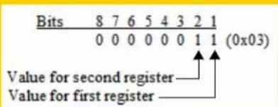
text_image
Bits 8 7 6 5 4 3 2 1 0 0 0 0 0 0 1 1 (0x03) Value for second register Value for first registerError Codes
| Code Name Description | ||
| 01 | Illegal Function | The function code received in the query is not an allowable action for the server (or slave). |
| 02 | Illegal Data Address | The data address received in the query is not an allowable address for the server (or slave). |
| 03 | Illegal Data Value | A value contained in the query data field is not an allowable value for server (or slave). |
| 04 | Slave Device Failure | An unrecoverable error occurred while the server (or slave) was attempting to perform the requested action. |
I/O SNMP Traps
When you enable SNMP traps for Digital and Analog inputs, a value is returned when an alarm triggers or clears. This section decodes the SNMP specific trap numbers. The value returned from the trap will be the I/O channel number that is generating the trap.
| Specific Trap # | Alarm Description | |
| 1 IO_DI_ALARM_SENSOR Trap for the Digital input Trigger. | ||
| 2 | IO_DI_ALARM_SERIAL_DSR | Trap for the Digital input DSR serial pin Trigger. |
| 3 | IO_DI_ALARM_SERIAL_DCD | Trap for the Digital input DCD serial pin Trigger. |
| 4 | IO_DI_ALARM_SERIAL_CTS | Trap for the Digital input CTS serial pin Trigger. |
| 5 | IO_AI_ALARM_LEVEL1 | Trap for Analog input Alarm Level 1. |
| 6 | IO_AI_ALARM_LEVEL2 | Trap for Analog input Alarm Level 2. |
| 7 | IO_AI_ALARM_LEVEL3 | Trap for Analog input Alarm Level 3. |
| 8 | IO_AI_ALARM_LEVEL4 | Trap for Analog input Alarm Level 4. |
| 9 | IO_AI_ALARM_LEVEL5 | Trap for Analog input Alarm Level 5. |
| 10 | IO_DI_ALARM_SENSOR_CLEAR | Trap for Digital input trigger Clear Mode. |
| 11 | IO_DI_ALARM_SERIAL_DSR_CLEAR | Trap for Digital input DSR serial pin trigger Clear Mode. |
| 12 | IO_DI_ALARM_SERIAL_DCD_CLEAR | Trap for Digital input DCD serial pin trigger Clear Mode. |
| 13 | IO_DI_ALARM_SERIAL_CTS_CLEAR | Trap for Digital input CTS serial pin trigger Clear Mode. |
| 14 | IO_AI_ALARM_LEVEL1_CLEAR | Trap for the Analog input Alarm Level 1 Clear. |
| 15 | IO_AI_ALARM_LEVEL2_CLEAR | Trap for the Analog input Alarm Level 2 Clear. |
| 16 | IO_AI_ALARM_LEVEL3_CLEAR | Trap for the Analog input Alarm Level 3 Clear. |
| 17 | IO_AI_ALARM_LEVEL4_CLEAR | Trap for the Analog input Alarm Level 4 Clear. |
| 18 | IO_AI_ALARM_LEVEL5_CLEAR | Trap for the Analog input Alarm Level 5 Clear. |

text_image
10Configuring the Option Card
Introduction
SCS models have a built-in option card slot that supports one of the following options cards (purchased separately):
Perle IOLAN modem card
PCMCIA Wireless Wan card
USB modem card
Fiber optic card offered in Fast Ethernet or Gigabit speeds.
Perle PCI Adapter card for use with a user supplied USB modem card.
Perle PCI Adapter card for use with a user supplied wireless WAN card.
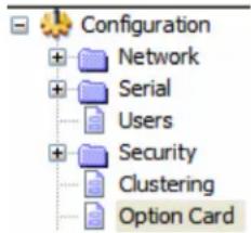
text_image
Configuration + Network + Serial Users + Security Clustering Option CardOption Card Settings
Overview
The Option Card settings allow you to configure the option card slot for the specific card being installed in the unit.IOLAN.
Functionality
In order to activate the “option card” you must install the card into the PCI slot of the IOLAN and configure the operating parameters.
To install the option card, please follow the instruction IOLAN described in Installing a Perle PCI Card.
Configuring the IOLAN Modem Card
The IOLAN Modem card Configure button automatically takes you to the Terminal serial port profile, although you can set and configure any serial port profile appropriate for modem use. See the Chapter E, Configuring Serial Ports for information on the configuration options for the serial port profile that fits your modem usage.
Configuring a Wireless (PCMCIA) WAN Card
Overview
SCS IOLAN models support a wireless WAN card that can be installed to permit access to the IOLAN via the internet or other WAN network. If you are using a USB modem, please see Configuring a USB Modem . When the PCI card type has been configured to be a Wireless WAN card, the serial port associated with the wireless WAN card is automatically set to PPP. No other PPP configuration is typically required. The wireless WAN card will establish a GPRS data connection over the service provider's GSM network. The service provider will assign an IP address to your wireless connection. This address may be public or private and it may be dynamically or statically assigned, depending on the type of account established with the service provider. If a static, public IP address has been assigned, the IOLAN will be directly accessible via that IP address. If a dynamic, public IP address has been assigned, you may access your IOLAN with the assistance of a dynamic DNS service provider. These service providers provide a method of accessing your device server using a standard URL (for example, yourcompany.dyndns.org), when the IP address assigned by the Wireless provider is dynamic. The IOLAN SCS supports dynamic DNS updates to DynDNS.com (see www.DynDNS.com for more information).
Field Descriptions
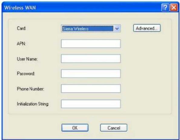
text_image
Wireless WAN Card: Sierra Wireless Advanced... APN: User Name: Password: Phone Number: Initialization String OK CancelConfigure the following parameters:
Card Specify the wireless WAN card you are using.
Data Options:
- Sierra Wireless AirCard 881—You are using a Sierra Wireless AirCard 881 WAN card.
- Sony Ericsson PC300—You are using a Sony Ericsson PC300 wireless WAN card.
- Sierra Wireless—You are using a Sierra wireless WAN card.
- Sony Ericsson—You are using a Sony Ericsson wireless WAN card.
- Use Standard Driver—If the wireless WAN card you are using is not listed, try the standard driver.
- Use Custom Driver—A custom driver downloaded from the Perle website.
Default: Sierra Wireless AirCard 881
APN Specify the APN required by your internet provider to access their network. See the internet provider documentation for more information.
User Name Specify the name required by your internet provider to access their network.
Password Specify the password required by your internet provider to access their network.
Phone Number Specify the phone number provided by your service provider to access their wireless network.
Field Format: Probably similar to *99***1#
Initialization String Specify the initialization string required by your internet service provider for your wireless modem.
When you click the Advanced button, the Remote Access (PPP) profile is displayed. The wireless WAN card uses PPP to communicate with its wireless provider. See Remote Access (PPP) Profile for information on how to configure PPP.
Configuring a USB Modem
Overview
SCS IOLAN models support a USB Wireless Modem that can be installed to permit access to the IOLAN via the internet or other WAN network. If you are using a PCMCIA Wireless Card, See Configuring a Wireless (PCMCIA) WAN Card. When the PCI card type has been configured to be USB, the serial port associated with the USB Modem is automatically set to PPP. No other PPP configuration is typically required. The USB Modem will establish a GPRS data connection over the service provider's GSM network. The service provider will assign an IP address to your wireless connection. This address may be public or private and it may be dynamically or statically assigned, depending on the type of account established with the service provider. If a static, public IP address has been assigned, the IOLAN will be directly accessible via that IP address. If a dynamic, public IP address has been assigned, you may access your IOLAN with the assistance of a dynamic DNS service provider. These service providers provide a method of accessing your device server using a standard URL (for example, yourcompany.dyndns.org), when the IP address assigned by the Wireless provider is dynamic. The IOLAN SCS supports dynamic DNS updates to DynDNS.com (see www.DynDNS.com for more information).
Field Descriptions
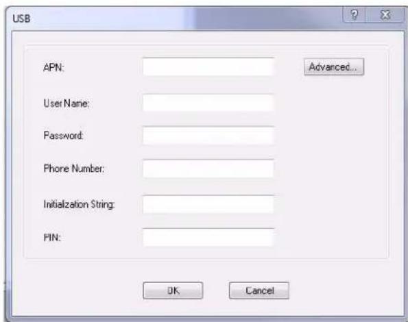
text_image
USB APN: User Name: Password: Phone Number: Initialization String: PIN: Advanced... OK CancelConfigure the following parameters:
APN Specify the APN required by your internet provider to access their network. See the internet provider documentation for more information.
User Name Specify the name required by your internet provider to access their network.
Password Specify the password required by your internet provider to access their network.
Phone Number Specify the phone number provided by your service provider to access their wireless network.
Field Format: Probably similar to *99***1#
Initialization String Specify the initialization string required by your internet service provider for your wireless modem.
PIN If you have locked your SIM using a PIN, you must enter this PIN here in order to allow the IOLAN to access it. If you have never locked your SIM card, leave this field blank. You can enter up to 8 digits for the PIN.
When you click the Advanced button, the Remote Access (PPP) profile is displayed. The USB modem uses PPP to communicate with its wireless provider. See Remote Access (PPP) Profile for information on how to configure PPP.
Configuring a Fiber Optic Card
Overview
SCS IOLAN models support the ability to replace the second Ethernet interface with a fiber optic connection.
Field Descriptions
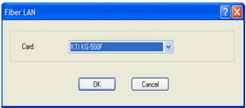
text_image
Fiber LAN Card: KTI KG-500F OK CancelConfigure the following parameters:
Card
Specify the type of fiber card you will be using.
• KTI KG-500F—Gigabit fiber card.
• Transition Networks N-FX-SC5-02—100MB card.
The type selected must match the card installed in the PCI slot.
No additional configuration is required for the fiber card.
The fiber card will now replace the second Ethernet interface on the unit. All configuration parameters related to "Interface 2" will now apply to the fiber card. If the options card configuration is changed to "None" or the card is removed from the PCI slot, the second Ethernet interface will be come active again using the configuration parameters for "Interface 2".

text_image
11Configuring Clustering
Introduction
Clustering is a way to provide access to the serial ports of many IOLANs through a single IP address.
Clustering Slave List
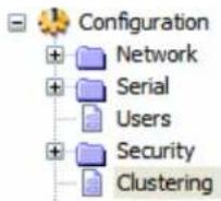
Overview
The IP address that will be used to access all clustered serial ports will be that of the Master IOLAN in the cluster. All other IOLANs in the cluster will be referred to as Slave IOLANs. Users can also access slave serial ports using EasyPort Web; EasyPort Web is automatically launched when a user types in the IP address of the Master IOLAN in a web browser. If the user has Admin privileges, the WebManager will first be displayed with an option to proceed to EasyPort Web.
The Clustering Slave List window displays the slave IOLAN entries and the number of ports on those slave IOLANs.
No special configuration is required on the Slave IOLANs to enable this functionality.
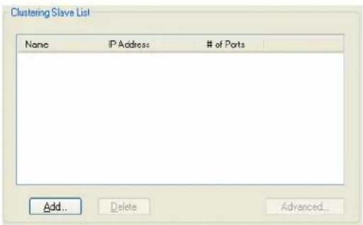
text_image
Clustering Slave List Name IP Address # of Ports Add... Delete Advanced...The following buttons are available:
| Add Button | Click this button to display a window to configure and add a new Slave IOLAN’s configuration to the clustering group.SeeAdding Clustering Slaveson page 229for more information. |
| Delete Button | Select a Slave IOLAN and click this button to delete it from the clustering group. |
| Advanced Button | Select a Slave IOLAN and click this button to configure the individual Slave IOLAN’s serial ports.SeeAdvanced Clustering Slave Optionson page 230for more information. |
Adding Clustering Slaves
Overview
When you add a clustering slave IOLAN entry, you are adding the IOLAN that users will access through this master IOLAN.
Field Descriptions
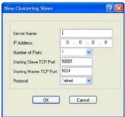
text_image
New Clustering Slave Server Name: 1 IP Address: 0 . 0 . 0 . 0 Number of Potts: 1 Starting Slave TCP Port: 10001 Starting Master TCP Port: 1024 Protocol: Telnet OK CancelConfigure the following parameters:
| Server Name | Specify a name for the slave IOLAN in the clustering group. This name does not have to correspond to the proper host name, as it is just used within the IOLAN.Field Format: Maximum 15 alphanumeric characters, including spaces |
| IP Address | Specify the IP address of the slave IOLAN in the clustering group.Field Format: IPv4 |
| Number of Ports | Specify the number of ports in the Slave IOLAN that you are adding to the clustering group.Data Options: 1, 2, 4, 8, 18, 24, 36, 48Default: 1 |
| Starting Slave TCP Port | Specify the first TCP Port number (as specified in the slave IOLAN’s serial port configuration) on the slave host.Default: 10001, and increments by one for each serial port |
| Starting Master TCP Port | Specify the TCP port number you want to map the first slave IOLAN DS Port number to. This number should not be a port number that is already in use by the master IOLAN.Default: 1024, and then increments by one for each new slave entry |
| Protocol | Specify the protocol that will be used to access the slave IOLAN port.Data Options: SSH, TelnetField Format: Telnet |
Advanced Clustering Slave Options
Overview
The Advanced button provides a means of configuring each individual serial port's name, connection protocol, and port association in the clustered IOLAN slave. The Clustering Slave Settings window displays each clustered serial port slave entry, you need to click the Edit button to configure the individual serial port settings.
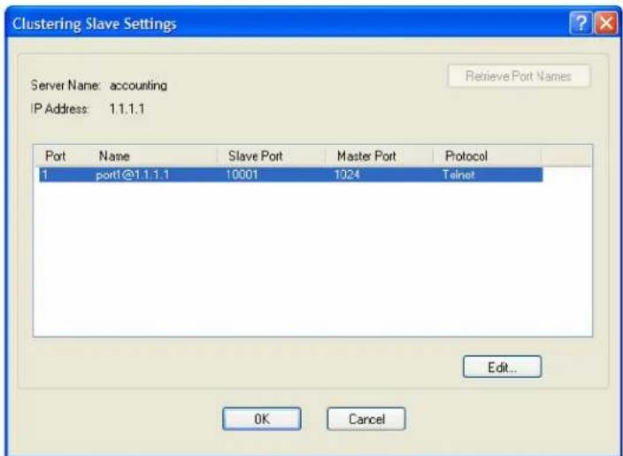
text_image
Clustering Slave Settings Server Name: accounting IP Address: 1.1.1.1 Retrieve Port Names Port Name Slave Port Master Port Protocol 1 port@1.1.1.1 10001 1024 Telnet Edit... OK CancelIf you click the Retrieve Port Names button, the DeviceManager will connect to the clustering slave IOLAN and download all the serial port names--you can change the names and other settings when you click the Edit button.
Editing Clustering Slave Settings
Change the individual serial port settings Slave Port Settings window.
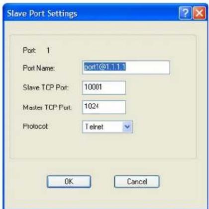
text_image
Slave Port Settings Port 1 Port Name: port1@1.1.1 Slave TCP Port: 10001 Master TCP Port: 1024 Protocol: Telnet OK CancelConfigure the following parameters:
Port Name Specify a name for the port.
Default: A combination of the port number, the @ symbol, and the IP address; for example, port1@172.22.23.101.
Slave TCP Port Specify the TCP Port number configured on the Slave IOLAN that is associated to the port number you are configuring.
Range: 1-99999
Master TCP Port Specify the TCP port number you want to map to the Slave IOLAN TCP Port. User's will use this TCP port number to access the Slave IOLAN's port.
Default: 1024, and then increments by one for each new slave entry
Protocol Specify the protocol that will be used to access the port.
Data Options: SSH, Telnet
Default: Telnet

text_image
12Configuring the System
Introduction
This chapter describes the alerts (email and syslog) that can be configured for the IOLAN and the advanced options (SNMP, time, custom applications/plugins, and other miscellaneous configuration options) that you will want to look at to see if they are required for your implementation.
Alerts
Email Alerts
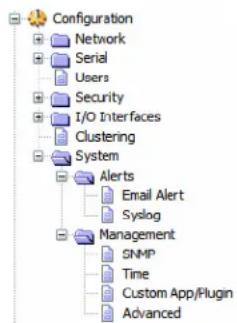
text_image
Configuration Network Serial Users Security I/O Interfaces Clustering System Alerts Email Alert Syslog Management SNMP Time Custom App/Plugin AdvancedOverview
Email notification can be set at the Server and/or Line levels. You can set email notification at these levels because it is possible that the person who administers the IOLAN might not be the same person who administers the serial device(s) attached to the IOLAN port. Therefore, email notification can be sent to the proper person(s) responsible for the hardware.
Functionality
Email notification requires an SMTP host that is accessible by the IOLAN to process the email messages sent by the IOLAN. When you enable email notification at the Server level, you can also use those settings at the serial port level, or you can configure email notification specifically for each serial port. When you choose an event Level, you are selecting the lowest notification level; for example, if you select Level Error, you will get notifications for all events that trigger Error, Critical, Alert, and Emergency messages. The level order, from most inclusive to least inclusive, is as follows: Debug, Info, Notice, Warning, Error, Critical, Alert, Emergency.
The following events trigger an email notification on the System for the specified Level:
- Reboot, Alert Level
• IOLAN System Failure, Error Level
• Authentication Failure, Notice Level - Successful Login, Downloads (all), Configuration Save Commands, Info Level
Field Descriptions
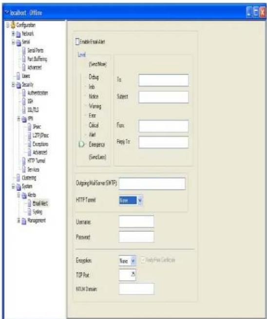
text_image
localhost - Offline Configuration Network Serial Serial Ports Part Duffering Advanced Users Security Authentication ISP SQL/TLS IPPI Psec LFTP/Proc Exceptions Advanced HTTP Tunnel Services Clustering System Airbus Email Net Systing Management Enable Email Alert Level (Send Note) Debug Info Notice Warning Error Citicul Alert Emergency (Send Line) To: Subject: Func: Reply To: Outgoing MailServer (SMTP): HTTP Tunnel: None Username: Password: Encryption: None TCP Port: MYLN Domain:Configure the following parameters:
Enable Email Alert Enables/disables a global email alerts setting. Even if this option is disabled, you can still configure individual serial port email alerts. When this option is enabled, individual serial ports can inherit these email alerts settings.
Default: Disabled
Level Choose the event level that triggers an email notification.
Data Options: Emergency, Alert, Critical, Error, Warning, Notice, Info, Debug Default: Emergency
To An email address or list of email addresses that will receive the email notification.
Subject A text string, which can contain spaces, that will display in the Subject field of the email notification.
From This field can contain an email address that might identify the IOLAN name or some other value.
Reply To The email address to whom all replies to the email notification should go.
Outgoing Mail Server The SMTP host (email server) that will process the email notification request. This can be either a host name defined in the IOLAN host table or the SMTP host IP address.
HTTP Tunnel Specify the HTTP tunnel to be used for this connection.
Username If your mail server requires you to authenticate with it before it will accept email messages, use this field to configure the authorized user name. Maximum size of user name is 64 characters.
Password Enter the password associated with the user configured in "Username". Maximum size of password is 64 characters.
Encryption Choose the type of encryption desired. Valid options are;
None - All information is sent in the clear.
SSL - Select this if your email server requires SSL.
TLS - Select this if your email server requires TLS
Verify Peer Certificate When checked this will enable the validation of the certificate presented by the email server. To validate the certificate, you will need to download the
When checked this will enable the validation of the certificate presented by the email server. To validate the certificate, you will need to download the appropriate CA list into the IOLAN. If the certificate is not found to be valid, the communication with the email server will be terminated. No authentication will take place and the email message will not be forwarded to the email server. If this option is not checked, the certificate validation will still be attempted but if it fails, a syslog message will be generated but the authentication and forwarding of the email will still take place.
Default: Enabled if SSL or TLS encryption is selected. Disabled if no encryption is selected.
TCP Port This is the TCP port used to communicate with the email server.
Default: 25 for non-SSL, 465 if SSL/TLS is used
NTLM Domain This field is only used if SPA authentication is performed with the email server. It may or may not be required. If the email server does not expect this field, it can be left blank.
Syslog
Overview
The IOLAN can be configured to send system log messages to a syslog daemon running on a remote host if the Syslog service is activated. You can configure a primary and secondary host for the syslog information and specify the level for which you want syslog information sent.
You must ensure that the Syslog Client service in the Security, Services window is enabled (by default it is enabled) for these settings to work.
Field Descriptions
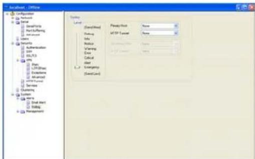
text_image
Network - Default Configuration Network Name Defaulting Part/Burkering Advanced Users Security Authentication SaaS USB/33 GPS Photo L2P/33/33 Electronic Advanced v100/100/100 Services Outperform System Home Small Array Timing Management Location [Standard] Address Address Address Card Priority/Host None Mid IP Layout None Address Address CardConfigure the following parameters:
| Primary Host | The first preconfigured host that the IOLAN will attempt to send system log messages to; messages will be displayed on the host’s monitor.Default: None |
| Secondary Host | If configured, the IOLAN will attempt to send system log messages to this syslog host as well as the primary syslog host defined. Messages will be displayed on the host’s monitor.Default: None |
| HTTP Tunnel | Specify the HTTP tunnel to be used for this connection. |
| Level | Choose the event level that triggers a syslog entry.Data Options: Emergency, Alert, Critical, Error, Warning, Notice, Info, DebugDefault: Emergency |
Management
SNMP
Overview
If you are using SNMP to manage/configure the IOLAN, or to view statistics or traps, you must set up a User in SNMP version 3 or a Community in SNMP version 1.2 to allow your SNMP manager to connect to the IOLAN; this can be done in the DeviceManager, WebManager, CLI, or Menu. You must then load the perle-sds.MIB (found on the CD-ROM packaged with the IOLAN) file into your SNMP manager before you connect to the IOLAN.
Ensure that the SNMP service found in the Security, Services page is enabled (by default it is enabled).
SNMP Tab Field Descriptions
Configure the following parameters:
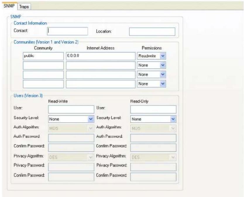
text_image
SNMP Traps SNMP Contact Information Contact: 1 Location: Communities (Version 1 and Version 2) Community Internet Address Permissions public 0.0.0.0 Readwrite None None None Users (Version 3) User: Read-Write User: Read-Only Security Level: None Security Level: None Auth Algorithm: MUS Auth Algorithm: MUS Auth Password: Auth Password: Confirm Password: Confirm Password: Privacy Algorithm: DES Privacy Algorithm: DES Privacy Password: Privacy Password: Confirm Password: Confirm Password:Contact The name and contact information of the person who manages this SMNP node.
Location The physical location of the SNMP node.
Community The name of the group that devices and management stations running SNMP belong to. Community only applies to SNMP v1 and v2c
| Internet Address | The IP address of the SNMP manager that will send requests to the IOLAN. If the address is 0.0.0.0, any SNMP manager with the Community name can access the IOLAN. If you specify a network address, for example 172.16.0.0, any SNMP manager within the local network with the Community name can access the IOLAN.Field Format: IPv4 or IPv6 address |
Permissions Permits the IOLAN to respond to SNMP requests.
Data Options:
- None—There is no response to requests from SNMP.
- Readonly—Responds only to Read requests from SNMP.
- Readwrite—Responds to both Read and Write requests from SNMP.
Default: None
V3 Read-write User This user can view and edit SNMP variables.
| V3 Read-Write Security Level | Select the security level for the Read-Writer user. This must match the configuration set up in the SNMP manager. |
| Data Options:None—No security is used.Auth—User authentication is used.Auth/Priv—User authentication and privacy (encryption) settings are used.Default: None |
| V3 Read-Write Auth Algorithm | Specify the authentication algorithm that will be used for the read-write user. |
| Data Options: MD5, SHA | |
| Default: MD5 |
| V3 Read-Write Auth Password | Type in the read-write user’s authentication password. |
| V3 Read-Write Auth Password | Retype the user’s authentication password. |
| V3 Read-Write | Specify the read-write user's privacy algorithm (encryption). |
| Privacy Algorithm | Data Options: DES, AESDefault: DES |
| V3 Read-Write Privacy Password | Type in the read-write user's privacy password. |
| V3 Read-Write | Retype the privacy password. |
V3 Read-Only User This user can only read SNMP variables.
V3 Read-Only Security Level Select the security level for the Read-Only user. This must match the configuration set up in the SNMP manager.
Data Options:
- None—No security is used.
- Auth—User authentication is used.
- Auth/Priv—User authentication and privacy (encryption) settings are used.
Default: None
V3 Read-Only Auth Specify the authentication algorithm that will be used for the read-only user.
Algorithm
Data Options: MD5, SHA
Default: MD5
V3 Read-Only Auth Type in the read-only user's authentication password.
Password
V3 Read-Only Retype the user's authentication password.
Confirm Password
V3 Read-Only Specify the read-only user's privacy algorithm (encryption).
Privacy Algorithm Data Options: DES, AES
Default: DES
V3 Read-Only Type in the read-only user's privacy password.
Privacy Password
V3 Read-Only Retype the privacy password.
Confirm Password
SNMP Traps Tab Field Descriptions
Configure the following parameters:
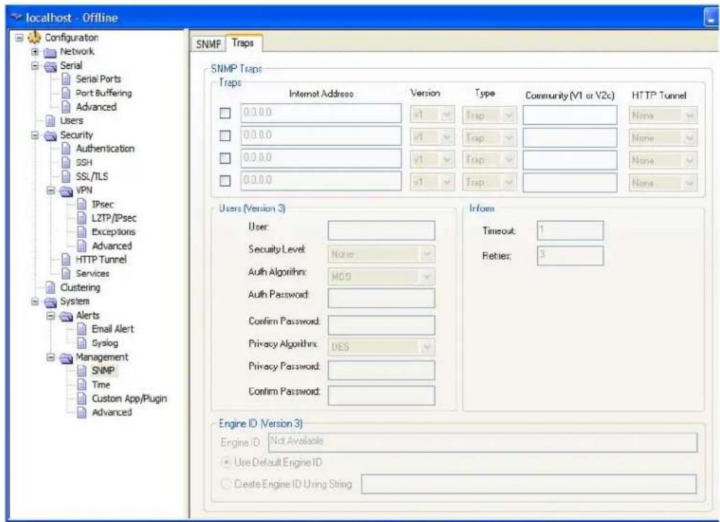
text_image
localhost - Offline Configuration Network Serial Serial Ports Port Buffering Advanced Users Security Authentication SSH SSL/TLS VPN IPsec LZTP/IPsec Exceptions Advanced HTTP Tunnel Services Clustering System Alerts Email Alert Syslog Management SNMP Time Custom App/Plugin Advanced SNMP Traps Traps Internet Address Version Type Community (V1 or V2c) HTTP Tunnel 0.0.0.0 V1 Trap None 0.0.0.0 V1 Trap None 0.0.0.0 V1 Trap None 0.0.0.0 V1 Trap None Users (Version 3) User: Security Level: None Auth Algorithm: MDS Auth Password: Confirm Password: Privacy Algorithm: DES Privacy Password: Confirm Password: Inform Timeout: 1 Reties: 3 Engine ID (Version 3) Engine ID: Not Available Use Default Engine ID Create Engine ID Using StringTrap checkbox
Check this box to enable the entry of the trap information.
Internet Address The IP address of the SNMP manager(s) that will receive messages from the IOLAN.
Field Format: IPv4 or IPv6 address
| Version | Select the version of trap you want the IOLAN to send. Valid options are v1, v2c or v3.Default: v1 |
| Type | Select between Trap and Inform. Inform requires the host receiving the trap to acknowledge the receipt of the trap. |
| Community The name of the group that devices and management stations running SNMP belong to. Community only applies to SNMP v1 and v2c |
| HTTP Tunnel Specify the HTTP tunnel to be used for this connection. |
| Timeout | This is only used for Inform traps. Select the number of seconds to wait for the acknowledgement of the trap. |
| Default: 1 second |
| Retries | This is only used for Inform traps. Select the number of times the trap will be sent if no acknowledgement is received. |
| Default: 3 |
| V3 Trap User | This field identifies the system sending the traps to the host receiving the traps. Same user name is used for all traps sent by this system. |
| V3 Trap Security Level | Select the security level for the V3 traps. This must match the configuration set up in the SNMP manager. |
Data Options:
• None—No security is used.
- Auth—Trap authentication is used.
- Auth/Priv—Trap authentication and privacy (encryption) settings are used.
| Default: None |
| V3 Trap Auth Algorithm | Specify the authentication algorithm that will be used for the read-only user. |
| Data Options: MD5, SHA |
| Default: MD5 |
| V3 Trap AuthPassword | Type in the password associated with traps sent from this host. |
| V3 Trap Confirm Password | Re-enter the password associated with traps sent from this host. |
| V3 Trap Privacy | Specify the privacy algorithm (encryption) which will be used with traps. |
| Data Options: DES, AES |
| Default: DES |
| V3 Trap Privacy Password | Type in the password associated with the encryption method being used for traps. |
| V3 Trap Confirm Password | Re-type the password associated with the encryption method being used for traps. |
| V3 EngineID | This is the current engine ID. The Engine ID is a string which uniquely identifies this SNMP agent. |
| V3 Use Default EngineID | When this field is selected, the firmware will use the default Engine ID. The default Engine ID is the MAC address of the Ethernet interface to ensure that the Engine ID is unique to this agent. |
| V3 Create EngineID Using String | The string entered in this field will be combined with the defined string in hex of 800007AE04 to form the Engine ID. Ensure each string is unique for each IOLAN on your network. |
Time
Overview
You can set standard and summer time (daylight savings time) in the IOLAN. You can specify the summer time settings as absolute, on a fixed date and time, or relative, on something like the third day of the third week at this time in June.
Functionality
The IOLAN has a real-time internal clock, allowing the date and time to be set and viewed. It will maintain the time over a short power outage and after reboots of the IOLAN. If you do not set the time, it will start the clock at the factory set time.
When you set the IOLAN's time, the connection method and time zone settings can affect the actual internal clock time that is being set. For example, if you are connecting to the IOLAN through the DeviceManager and your PC's time zone is set to Pacific Standard Time (GMT -8:00) and the IOLAN's time zone is set to Eastern Standard Time (GMT -5:00), the IOLAN's time is actually three hours ahead of your PC's time. Therefore, if you set the IOLAN's time to 2:30 pm in the DeviceManager, the IOLAN's actual internal clock time is 5:30 pm. This is the only configuration method that interprets the time and converts it between time zones, as necessary.
Network Time Tab Field Descriptions
You can configure your NTP/SNTP client in the IOLAN to automatically synchronize the IOLAN's time.
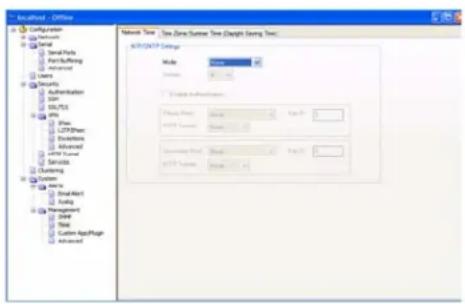
text_image
Configuration Configuration Serial Parts Part+Suffing Advanced Users Security Authentication SNP SULTS IPM LTP/SPN Settings Advanced SPN Server Service Customing System Email SmallMap1 Folding Management Order State Custom AppPage Advanced Network Type: Type Zone Custom Type (Length Saving Type) Network Settings Node: Newer Connect Subnets: Name: Newer Size: 0.0000000000000000000000000000000000000000000000000000000000000000000000000000000000000000000000000000 WNT-OPCP Settings WNT-OPCP Mode: Newer Size: 1.56725 WNT-OPCP Server: Newer: 1.56725 WNT-OPCP User: Newer: 1.56725 WNT-OPCP Account: Newer: 1.56725Configure the following parameters:
NTP/SNTP Mode The NTP/SNTP mode.
Data Options:
• None—NTP/SNTP is turned off.
- Unicast—Sends a request packet periodically to the Primary host. If communication with the Primary host fails, the request will be sent to the Secondary host.
- Broadcast/Multicast—Listen for any broadcasts from an NTP/SNTP server and then synchronizes its internal clock to the message.
- Manycast/Anycast—Sends a request packet as a broadcast on the LAN to get a response from any NTP/SNTP server. The first response that is received is used to synchronize its internal clock and then operates in Unicast mode with that NTP/SNTP server.
Default: None
NTP/SNTP Version Version of NTP/SNTP.
Range: 1-4
Default: 4
Enable Sets NTP/SNTP server authentication on or off.
Authentication Default: Off
Key ID Specify the key id associated with this host. This key must exist in the ntp/sntp (symmetric key) file that was downloaded to the IOLAN.
Valid key ID's: 1-65534
(Note: the structure for the ntp/sntp (symmetric key) file can be found in your IOLAN User's Guide - Appendix L)
Primary Host The name of the primary NTP/SNTP server from the IOLAN host table. Valid with Unicast and Multicast modes, although in Multicast mode, the IOLAN will only accept broadcasts from the specified host NTP/SNTP server.
Secondary Host The name of the secondary NTP/SNTP server from the IOLAN host table. Valid with Unicast and Multicast modes, although in Multicast mode, the IOLAN will only accept broadcasts from the specified host NTP/SNTP server.
HTTP Tunnel Specify the HTTP tunnel to be used for this connection.
Time Zone/Summer Time Tab Field Descriptions
You can configure an automatic summer time (daylight savings time) time change.
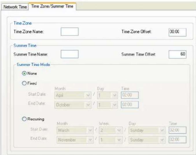
text_image
Network Time Time Zone/Summer Time Time Zone Time Zone Name: Time Zone Offset: 00:00 Summer Time Summer Time Name: Summer Time Offset: 60 Summer Time Mode None Fixed Start Date: April Day 1 Time 02:00 End Date: October 1 02:00 Recurring Start Date: March Week 2 Day Sunday 32:00 End Date: November 1 Sunday 02:00Configure the following parameters:
Time Zone Name The name of the time zone to be displayed during standard time.
Field Format: Maximum 4 characters and minimum 3 characters (do not use angled brackets < >)
Time Zone Offset The offset from UTC for your local time zone.
Field Format: Hours hh (valid -12 to +14) and minutes mm (valid 0 to 59 minutes)
Summer Time Name The name of the configured summer time zone; this will be displayed during the summer time setting. If this parameter is not set, then the summertime feature will not work.
Field Format: Maximum 4 characters and minimum 3 characters (do not use angled brackets < >)
Summer Time The offset from standard time in minutes. Valid values are 0 to 180.
Range: 0-180
Default: 60
Summer Time You can configure the summer time to take effect:
• None—No summer time change.
- Fixed—The summer time change goes into effect at the specified time every year. For example, April 15 at 1:00 pm.
- Recurring—The summer time changes goes into effect every year at same relative time. For example, on the third week in April on a Tuesday at 1:00 pm.
Default: None
Fixed Start Date Sets the exact date and time in which the IOLAN's clock will change to summer time (daylight saving time) hours.
Fixed End Date Sets the exact date and time in which the IOLAN's clock will end summer time hours and change to standard time.
Recurring Start Date
Sets the relative date and time in which the IOLAN's clock will change to summer time (daylight saving time) hours. Sunday is considered the first day of the week.
Recurring End Date Sets the relative date and time in which the IOLAN's clock will end summer time hours and change to standard time. Sunday is considered the first day of the week.
Custom App/Plugin
Overview
You can create custom applications for the IOLAN by using the Perle SDK. See the SDK Programmer's Guide (the SDK and guide are accessible via a request form located on the Perle website at www.perle.com/supportfiles/SDK_Request.shtml) for information about the functions that are supported. You must download the program and any ancillary files to the IOLAN and set the Serial Port Profile to Custom App/Plugin to run a custom application. You must also specify the program executable in the Command Line parameter.
A custom application or plugin can be run on the serial port. In this situation, the application will start once the serial port is activated and operate solely on the context of that serial port and any network communications related to that serial port. You could run a different custom application on each serial port. The serial port custom application or plugin is configured by specifying the Custom App/Plugin profile for the serial port.
The system level custom application or plugin will begin execution immediately following the system startup. It runs on the context of the whole system and can access network communications as well as any or all serial ports.
Field Description
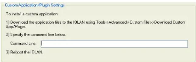
text_image
Custom Application/Plugin Settings: To install a custom application: 1) Download the application files to the IOLAN using Tools->Advanced->Custom Files->Download Custom App/Plugin. 2) Specify the command line below. Command Line: 3) Reboot the IOLAN.Configure the following parameter:
Command Line
The name of the application that has been already been downloaded to the IOLAN, plus any parameters you want to pass to the program. For example, using sample outraw program (this is sample program supplied with the SDK), you would type:
outraw -s 0 192.168.2.1:10001 Acct:10001
if you were starting the application on the Server (notice the -s 0 parameter specifies serial port 1 to this particular application).
Field Format: Maximum of 80 characters
Advanced
Overview
Review the configuration options in the Advanced page to determine if any of them apply to your implementation.
Advanced Tab Field Descriptions
Configure the following parameters:
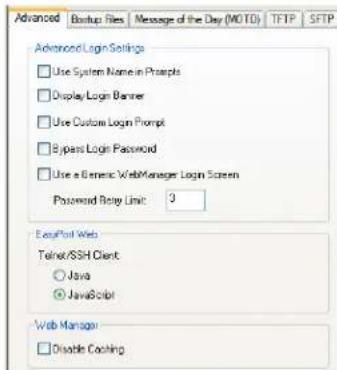
text_image
Advanced Backup Files Message of the Day (MOTO) TFTP SFTP Advanced Login Settings Use System Name in Prapls Display Login Banner Use Custom Login Prompt Bypass Login Password Use a Generic Web Manager Login Screen Password Relay Link: 3 EasyPort Web Telnet/SSH Client Java JavaScript Web Manager Disable Caching| Use System Name in Prompts | Displays the System Name field value instead of default product name. When enabled, the Server Name is displayed in the IOLAN login prompt, CLI prompt, WebManager login screen, and the heading of the Menu.Default: Disabled |
| Display Login Banner | This parameter concerns the banner information (product name/software version). This banner information is presented to a user with a login prompt. For security reasons, you can turn off the display of this information.Default: Disabled |
| Use Custom Login Prompt | When set, and a custom language file is in use, the login prompt and password prompt will use the string defined in the language file as the login prompt and password prompt instead of the default prompt,login:password:Default: Disabled |
| Bypass Login Password | When set, authorized users who do not have a password set, with the exception of the admin user, WILL NOT be prompted for a password at login with Local Authentication.Default: Disabled |
| Use a Generic WebManager Login Screen | When set, and the user connects to the IOLAN using WebManager, the WebManager login screen that is displayed is generic — the Perle banner, IOLAN model name, and firmware version are not displayed to the user.Default: Disabled |
| Password Retry Limit | The number of attempts a user is allowed to enter a password for a serial port connection from the network, before the connection is terminated and the user has to attempt to login again. For users logging into the serial port, if this limit is exceeded, the serial port is disabled for 5 minutes. A user with Admin level rights can restart the serial port, bypassing the timeout, by issuing a kill on the disabled serial port.Default: 3 |
| EasyPort Web | Select Java if communication is via port 23(Telnet) or port 22(SSH) and the IOLAN is not restricted by a firewall.Select Javascript if you need to communicate through a firewall on port 8080 using EasyPort Web.To end and close a Telnet session, type CTRL] then type quitTo end and close a SSH session, on a new line type ~ . (period). |
| Disable Caching | When this option is selected, the Web Manager will no longer cache web pages |
Bootup Files Tab Field Descriptions
You must have a SFTP/TFTP server running on any host that you are uploading or downloading files to/from. When you specify the file path, the path must be relative to the default path set in your SFTP/TFTP server software.
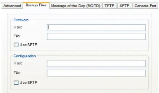
text_image
Advanced Backup Files Message of the Day (MOTD) TFTP SFTP Console Port Firmware Host: File: Use SFTP Configuration Host: File: Use SFTPConfigure the following parameters:
| Firmware Host | The host name or IP address of the server that contains the firmware file. If you use a host name, it must exist in the IOLAN’s host table or be resolved by DNS.Field Format: Resolvable host name, IPv4 address, IPv6 address |
| Firmware File | The path and file name, relative to the default path of your TFTP server software, of the update software for the IOLAN that will be loaded when the IOLAN is rebooted. |
| Firmware, Use SFTP | *Check this box if you wish to use SFTP (Secure File Transfer Protocol) instead of TFTP (Trivial File Transfer Protocol). The IOLAN will use the SFTP server information entered under the SFTP tab. |
| Configuration Host | The host name or IP address of the server that contains the configuration file. If you use a host name, it must exist in the IOLAN’s host table or be resolved by DNS.Field Format: Resolvable host name, IPv4 address, IPv6 address |
Configuration File
The path and file name, relative to the default path of your TFTP server software, of the configuration file for the IOLAN that will be loaded when the IOLAN is rebooted.
Configuration, Use SFTP
Check this box if you wish to use SFTP (Secure File Transfer Protocol) instead of TFTP (Trivial File Transfer Protocol). The IOLAN will use the SFTP server information entered under the SFTP tab.
Message of the Day (MOTD) Tab Field Descriptions
The message of the day is displayed when users log into the IOLAN through a telnet or SSH session or through WebManager or EasyPort Web.
There are two ways to retrieve the message of the day to be displayed to users when they log into the IOLAN:
- The message of the day file is retrieved from a SFTP/TFTP server every time a user logs into the IOLAN. You must have a SFTP/TFTP server running on any host that you are uploading or downloading files to/from when using SFTP/TFTP. When you specify the file path, the path must be relative to the default path set in your SFTP/TFTP server software.
- The message of the day file is downloaded to the IOLAN and retrieved locally every time a user logs into the IOLAN. You can download an MOTD file to the IOLAN in the DeviceManager by selecting Tools, Advanced, Custom Files and then selecting the Download Other File option and browse to the MOTD file. In WebManager, select Administration, Custom Files and select the Other File option and browse to the MOTD file. After the MOTD is downloaded to the IOLAN, you must specify the MOTD file name in the Filename field to access it as the message of the day (no SFTP/FTP Host parameter is required when the file is internal).
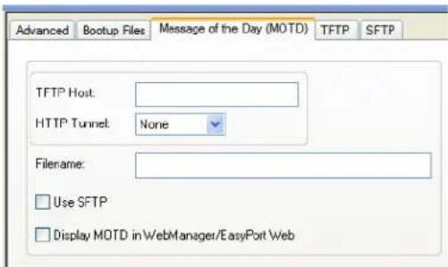
text_image
Advanced Bootup Files Message of the Day (MOTD) TFTP SFTP TFTP Host: HTTP Tunnel: None Filename: Use SFTP Display MOTD inWebManager/EasyPort WebConfigure the following parameters:
TFTP Host The host that the IOLAN will be getting the Message of the Day file from.
Field Format: Resolvable host name, IPv4 address, IPv6 address
Filename
The path and file name, relative to the default path of your TFTP server software, of the file that contains a string that is displayed when a user connects to the IOLAN. The IOLAN will look for the file internally (it must already be downloaded), if only the file is specified (no TFPT host) or the file cannot be found on the specified TFPT host.
HTTP Tunnel Specify the HTTP tunnel to be used for this connection.
Use SFTP
Check this box if you wish to use SFTP (Secure File Transfer Protocol) instead of TFTP (Trivial File Transfer Protocol). The IOLAN will use the SFTP server information entered under the SFTP tab.
Display MOTD in WebManager/EasyPort Web
When enabled, displays the Message of the Day to users who are logging into WebManager or EasyPort Web.
Default: Disabled
TFTP Tab Field Descriptions
You must have a TFTP server running on any host that you are uploading or downloading files to/from.
TFTP file transfers send via UDP packets. When the packet delivery is interrupted for any reason and a timeout occurs, that packet is resent if the retry count allows it. Therefore, if a very large file is being transferred and is interrupted, the entire file is not resent, just the part of the file that was not received.
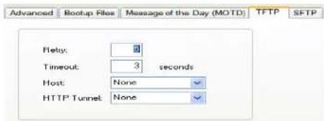
text_image
Advanced Backup Files Message of the Day (MOTD TFTP SFTP Flaky: 0 Timeout: 3 seconds Host: None HTTP Tunnel: NoneConfigure the following parameters:
| Retry | The number of times the IOLAN will retry to transmit a TPFT packet to/from a host when no response is received. A value of 0 (zero) means that the IOLAN will not attempt a retry should TFTP fail.Range: 0-5Default: 5 |
| Timeout | The time, in seconds, that the IOLAN will wait for a successful transmit or receipt of TFTP packets before retrying a TFTP transfer.Range: 3-10Default: 3 seconds |
| Host | Select the host entry from the IOLANs host table which corresponds to the FTP server. |
| HTTP Tunnel | Specify the HTTP tunnel to be used for this connection. |
SFTP Tab Field Descriptions
You must have a SFTP server running on any host that you are uploading or downloading files to/from.
These are global SFTP settings. They are used whenever the user specifies "SFTP" as the protocol to be used for the file transfer.
Some combinations of cipher groups are not available on FIPS firmware versions.
SSH-1 protocol is not available on FIPS firmware versions.
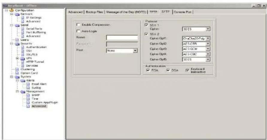
text_image
Specialist - Office Configuration Network IP Settings Advanced Send Serial Ports Port Buffering Advanced Users Security Authentication SSH SSL/FLS VPN HTTP Tunnel Services Clustering Option Card System Agents Email Alert Syslog Management SNMP Time Custom AppFllgn Advanced Advanced | Backup Files | Message of the Day (NOTD) | TFTP | SFTP | Console Put | Enable Compression Auto Login Name: Password: Host: None Protocol SSH 1 Cipher: 30 ES SSH 2 Cipher Opt1: CheChe20-Poly Cipher Opt2: AES-CTR Cipher Opt3: AES-GCM Cipher Opt4: AES-CBC Cipher Opt5: 30 ES Authentication RSA DSA Keyboard InteractiveConfigure the following parameters:
Enable Compression Enables compression of all data. Compression of data is desirable on slow connections, however on faster networks, compression will degrade overall data transmission rates.
Default: Disabled
Auto Logon When checked, the IOLAN will automatically log into the SFTP server using the Name field. If Keyboard Interactive is checked the IOLAN will also send the configured Password field.
Default: Disabled
Name Enter the user name that will be used to automatically log into the SFTP server.
Password Enter the password that will be used to automatically log in the SFTP server.
Host Select the host entry from the IOLANs host table which corresponds to the SFTP server.
HTTP Tunnel Specify the HTTP tunnel to be used for this connection.
SSH 1 enable Enable to negotiation of the SSH1 protocol.
SSH1 Cipher Select the encryption cipher to be used if the SSH1 protocol is used. Valid options are "3DES" or "Blowfish".
SSH 2 enable Enable to negotiation of the SSH2 protocol.
SSH2 Cipher Select the encryption cipher(s) to be used if the SSH2 protocol is used. You can provide up to five values in order of preference. Valid options are "3DES", "Blowfish", "AES-CBC", "CAST", "AES-CTR", "AES-GCM", ChaCha20-Poly1305 and "Arcfour".
Authentication RSA Allow RSA to be used as the method of authenticating the IOLAN.
Authentication DSA Allow DSA to be used as the method of authenticating the IOLAN.
Authentication Keyboard Interactive
Allow "Keyboard Interactive" to be used as the method of authenticating the IOLAN.
Console Port Tab Field Descriptions
This tab is found on rack mount models and is used to configure the Admin/Console port.
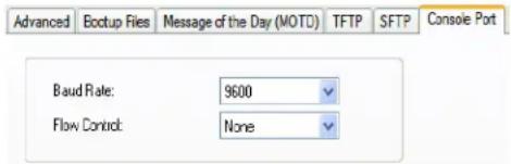
text_image
Advanced Baud Rate: 9600 Flow Control: NoneConfigure the following parameters:
Baud Rate Specifies the baud rate of the line connected to the dedicated console port.
Data Options: 9600, 19200, 38400, 57600, 115200
Default: 9600
Flow Control For IOLAN models that have a dedicated console port, defines how the data flow is handled.
Data Options:
- Soft—Data flow control is handled by the software.
- Hard—Data flow control is handled by the hardware.
- None—There is no data flow control.
Default: None

text_image
13Control RPS, I/O Channels, IPsec, WLANs
Introduction
The Control section appears when the IOLAN is connected to a Remote Power Switch and/or an I/O model, an IPsec tunnel is configured or you have configured a WLAN interface.
RPS Control
Overview
When a Remote Power Switch's (RPS) console port is attached to the IOLAN's serial port and the serial port is configured for the Power Management profile, you will be able to control the RPS's power plugs either universally or individually (power on/off the whole RPS or individual plugs).
Field Descriptions
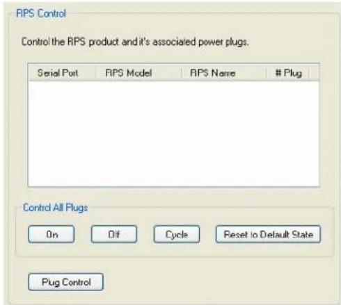
text_image
RPS Control Control the RPS product and it's associated power plugs. Serial Port RIPS Model RIPS Name # Plug Control All Plugs On Dif Cycle Reset to Default State Plug ControlThe following buttons are available:
On Button Turns all the RPS plugs on.
Off Button Turns all the RPS plugs off.
Cycle Button Turns all the RPS plugs off and then on.
Reset to Default State Button Resets all the RPS plugs to the default state as configured in the Power Management profile settings.
Plug Control Button Displays a window that allows you to manage the individual plugs on the RPS.
Plug Control
Overview
When you click the Plug Control button, you can power on/off individual plugs.
Field Descriptions
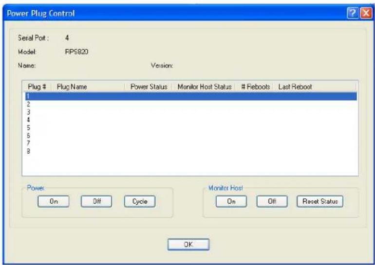
text_image
Power Plug Control Serial Pot: 4 Model: FPS820 Name: Version: Plug # Plug Name Power Status Monitor Host Status # Feboots Last Reboot 1 2 3 4 5 6 7 8 Power On Off Cycle Monitor Host On Off Retset Status OKThe "Power Status" field above can contain the following values;
- On - Power is currently being applied to the plug.
- Off - Power is currently not being applied to the plug.
The "Monitor Host Status" field above can contain the following values;
- Disabled - Feature is currently disabled.
- Discovering- Host has never responded to a PING. After a PING response is received once, the status will not return to “discovering until a reboot is performed or a “kill line” is issued on this port.
- Waiting reboot- Monitored host has not responded to all PING retries. It is now marked as needing a reboot and is executing the “delay before reboot” (if configured).
- Rebooting- The monitor host has determined that the host is not responding and has initiated a "power cycle" on the plug in order to re-boot the host.
• Monitoring- The host is being monitored and is responding to PING requests.
The “# Reboots” field above can contain the number of times that this power plug has been cycled due to a failure to respond to the PINGs.
The "Last Reboot" field above can contain the date and time of the last reboot to take place due to a failure to respond to the PINGs.
The following buttons are available:
Power
Controls the power state of the plug as follows;
On Button - Turns the selected plug on.
Off Button - Turns the selected plug off.
Cycle Button - Turns the selected plug off and then on.
Monitor Host
If host monitoring has been enabled on this plug, these buttons control the state of the feature as follows;
On Button - Enables the host monitor function.
Off Button - Disables the host monitor function.
Reset Statistics Button - Resets the “# reboots” and “Last Reboot” fields
OK Button
Closes the window.
Serial Port Power Control
Overview
The Serial Port Power Control window allows you to manage the power plugs that have been associated with the serial devices connected to the IOLAN.
Field Descriptions
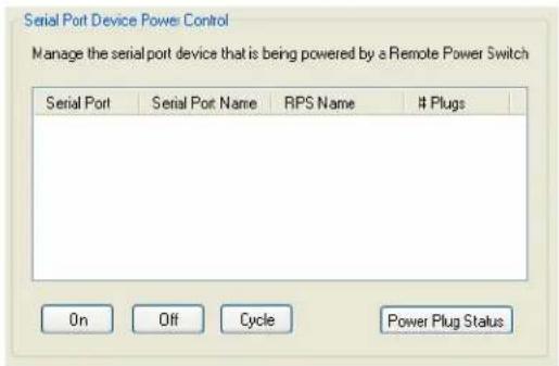
text_image
Serial Port Device Power Control Manage the serial port device that is being powered by a Remote Power Switch Serial Port Serial Port Name RPS Name # Plugs On Off Cycle Power Plug StatusThe following buttons are available:
On Button Turns the selected plug on.
Off Button Turns the selected plug off.
Cycle Button Turns the selected plug off and then on.
Power Plug Status Button Displays a window that provides the plug status for every plug associated with the serial port.
Power Plug Status
This Power Plug Status window displays the status of all the plugs associated with a serial port.
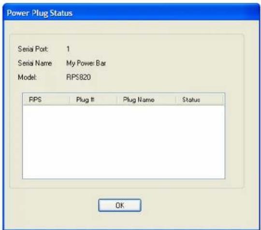
text_image
Power Plug Status Serial Port: 1 Serial Name My Power Bar Model: RPS820 FPS Plug # Plug Name Status OKClick OK to close this window.
I/O Channels
Overview
When the DeviceManager is connected to an I/O model IOLAN, the I/O Status/Control option is available. You can view the I/O status and manually control such options as clearing alarms, clearing minimum/maximum values, resetting the channel(s), and activating/deactivating output.
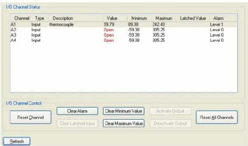
text_image
I/O Channel Status Channel Type Description Value Minimum Maximum Latched Value Alarm A1 Input thermocouple 99.79 89.38 242.43 Level 1 A2 Input Open -59.38 305.25 Level 0 A3 Input Open -59.38 305.25 Level 0 A4 Input Open -59.38 305.25 Level 0 I/O Channel Control Reset Channel Clear Alarm Clear Minimum Value Activate Output Reset All Channels Clear Latched Input Clear Maximum Value Deactivate Output RefreshThe following buttons are available:
Reset Channel Button Resets the highlighted channel (click on a channel to highlight it).
Clear Alarm Button Clears the alarm. Note that if the condition that tripped the alarm still exists, the alarm will not look like it's cleared, but will reflect the appropriate alarm level severity. Alarm Level 0 means that the alarm has not been triggered.
Clear Latched Clears the latched value. Input Button
Clear Minimum Value Button Clears the minimum value.
Clear Maximum Clears the maximum value. Value Button
Activate Output Button Manually activates the channel output.
Deactivate Output Manually deactivates the channel output. Button
Reset All Channels Resets all the channels. Button
Refresh Button Resets the highlighted channel (click on a channel to highlight it).
IPsec Tunnel Control
You can start, stop, and restart all the IPsec tunnels. When you start the IPsec tunnels, the Boot Action configured for each IPsec tunnel is what determines its state.
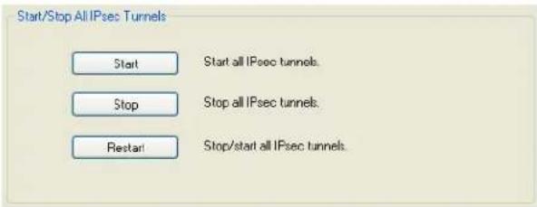
text_image
Start/Stop All IPsec Tunnels Start Start all IPsec tunnels. Stop Stop all IPsec tunnels. Restart Stop/start all IPsec tunnels.The following buttons are available:
Start Button Starts all IPsec VPN tunnels.
Stop Button Stops all IPsec VPN tunnels.
Restart Button Stops and then starts all IPsec VPN tunnels.
WLAN Control
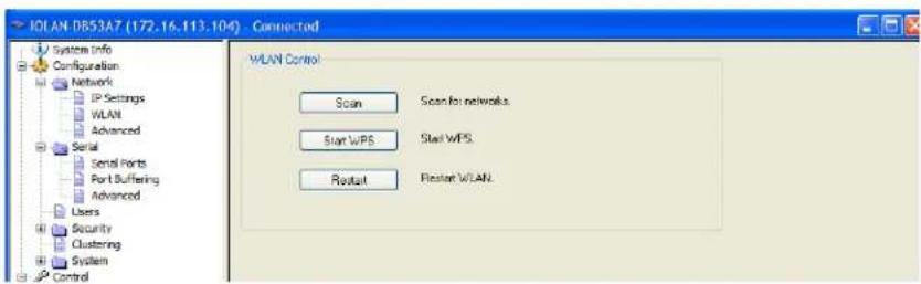
text_image
IOLAN DB53A7 (172.16.113.104) - Connected System Info Configuration Network IP Settings WLAN Advanced Serial Send Ports Port Buffering Advanced Users Security Clustering System Control WLAN Control Scan Scan for networks Start WPS Start WPS. Restart Restart WLAN.Scan
Overview
Scan
The IOLAN will scan the network for any broadcasting AP with the same SSID and security type.
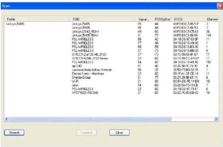
text_image
Scan Profile SSID Signal... RSSF(dB) BSSID Channel Linksyn25405 Linksyn25405 85 -44 48FB-B3C6-06-53* 3 Linksyn25405 Linksyn25405 85 -44 48FB-B3C6-06-53 3 Linksyn22040_5GHz Linksyn22040_5GHz 49 -65 48FB-B3C6-05-01 36 Linksyn25405 5GHz Linksyn25405 5GHz 31 -77 48FB-B3C6-06-54 143 PSLWIRELESS 88 -42 0A-18 D6 97 63-9F 11 PSLWIRELESS 77 -48 0A-18 D6 18 A9-30 1 PSLWIRELESS 60 -59 0A-18 D6 18 B3-40 1 PSLWIRELESS 37 -73 0A-18 D6 18 B8-01 6 DIRECT-ZNF50-ML-2160 37 -73 02-15-99A8-EF-DT 11 DIRECT-VAML-2160 Series 22 -82 02-15-99C47-A7 11 PSLWIRELESS 14 -97 0A-18 D6 19 A9-10 157 rpl242 81 -45 00:25-99C74-30 4 Lontrona Initial Adhoc Network 96 -37 36:5D-FB0 92:39 1 Electro Sonic - Markham 22 -83 88:1F-A1 2E-CE-18 11 SheldonGroup 31 -77 00:21:29 E8-65-14 6 WiFi 21 -83 80 FAEB FE 14 E8 10 dion 84 -83 00:25:AF5-15-CB 7 PSLWIRELESS 22 -82 0A-18 D6 97 73-17 6 HPCY1025-78E5AD 21 -83 02:2C-7C-B3-E8-82 10Profile The configured Profile names (upto 8 profiles). Profiles will be matched to a broadcasting AP with the same SSID and security type. Matching Profiles will be displayed at the top of the list and when highlighted will have the Connect Button highlighted in order to connect. Profiles without a matching AP and disabled profiles will not be on this list.
Note: Open-WEP, Shared-WEP or 802.1x-WEP security will be matched as equivalent.
SSID The configured network name or the network name assigned to the IOLAN when in Soft-AP mode.
Signal Displays the wireless signal strength.
RSSI
A measurement of the power level of the received radio signal (in dBm) of the currently associated AP averaged over time. Values = < then 95 dBm have no signal strength. Values >= -35 are at 100 strength.
BSSID
Shows whether the IOLAN is connected to this BSSID (Access Point's MAC Address).
Channel Displays the channel number that the IOLAN is using to connect to the AP. Value: (1-11 channels use 2.4GHz) and (36, 40, 44, 48 channels use 5GHz).
Type The network type displayed will be Infrastructure or Ad Hoc. The IOLAN cannot connect to Ad Hoc networks.
Security Displays the security type used for this connection between the IOLAN and the AP.
Start WPS
Start WPS The IOLAN will scan (120 seconds) all networks to find the closest AP that is currently in WPS mode. The IOLAN will exchange credentials with that AP and then create an internal wireless profile (association) and will then exit WPS mode.
Restart
Restart All WLANs will be stopped and any new configured WLAN parameters will be applied before the WLANs are restarted.

text_image
15System Administration
Introduction
This chapter addresses the functions that the admin user or a user with Admin Level privileges might do. This chapter uses the DeviceManager as the configuration method described in most administrative functions. As a general rule, administrative functions are accessed from the menu bar in the DeviceManager and under the Administration option in the WebManager's navigation tree.
Managing Configuration Files
Saving Configuration Files
When you connect to the IOLAN using either DeviceManager or WebManager, the IOLAN's active configuration file is loaded into the configurator. To save a backup of the configuration file locally, do the following:
• In DeviceManager:
-
From the menu bar, select File, Save As.
-
In the Save As dialog box, specify a name and format for the file. Notice that you can save the file as either a .dme or a .txt file. Either file format can be imported into the DeviceManager and downloaded to the IOLAN in the future. The .dme is a binary file and the .txt file is a text file that can be viewed in any text editor.
-
Click Save.
- In WebManager:
-
In the navigation tree, select the Administration option.
-
In the configuration area, click the Backup/Restore button.
-
Select the tab corresponding to the transfer method you wish to use. The options are;
• Web - Uses HTTP to transfer the data
TFTP - Uses Trivial File Transfer Protocol to transfer the data
- SFTP - Uses Secure File Transfer Protocol to transfer the data.
Note: For both TFTP or SFTP, you must have a host on your network which will act as the TFTP or SFTP server. HTTP does not require any other host.
-
In the Backup group box, select the format (Binary or Text) in which you want to save the file. Either file format can be imported into the DeviceManager and downloaded to the IOLAN in the future.
-
Click the Backup Configuration button.
Downloading Configuration Files
You can download a configuration file to the IOLAN by doing the following:
- In DeviceManager:
- Connect to the IOLAN to retrieve the current configuration file.
- Open the configuration file you want to download to the IOLAN by selecting File, Import Configuration from a File and then browsing to the configuration file. This will replace the retrieved configuration file.
- Select Tools, Download Configuration to IOLAN or click the Download All Changes button.
- Reboot the IOLAN.
- In WebManager:
- In the navigation tree, select the Administration option.
- In the configuration area, click the Backup/Restore button.
- Select the tab corresponding to the transfer method you wish to use. The options are;
- Web - Uses HTTP to transfer the data
TFTP - Uses Trivial File Transfer Protocol to transfer the data - SFTP - Uses Secure File Transfer Protocol to transfer the data.
Note: For both TFTP or SFTP, you must have a host on your network which will act as the TFTP or SFTP server. HTTP does not require any other host.
-
In the Restore group box, browse to the configuration file that you want to download to the IOLAN.
-
Click the Restore Configuration button.
-
Reboot the IOLAN.
Downloading Configuration Files to Multiple IOLANs
You can download a configuration file to multiple IOLANs at the same time by doing the following in DeviceManager (DeviceManager is the only configurator that does this function):
-
Select Tools, Download Configuration to Multiple IOLANs.
-
Specify the IOLANs that you want to download the configuration to:
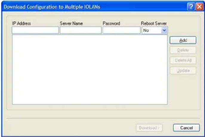
text_image
Download Configuration to Multiple IOLANs IP Address Server Name Password Reboot Server Add Delete Delete All Update Download > CancelEnter the following information for each IOLAN that you want to configure with the same configuration file:
| IP Address | Enter the IP address of the IOLAN that you want to download the configuration to.Field Format: IPv4 or IPv6 address |
| Server Name | The name of the IOLAN. The IOLAN name that you put in this field is passed into the configuration before it is downloaded to the IOLAN and cannot be left blank. |
| Password | Enter the admin user password for the IOLAN. |
| Reboot Server | Determines whether or not the IOLAN is rebooted after it has received the new configuration. The new configuration definitions will not go into effect until the IOLAN is rebooted. |
-
Click Add to add the IOLAN to the download list. You can also click on the IOLAN entry and edit any information and then click Update to make the edits permanent.
-
Click the Download> button to start the download process. A status window will display with the configuration download status.
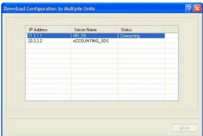
text_image
Download Configuration to Multiple Units IP Address Server Name Status 11.1.1.1 HR_DS Connecting... 22.2.2.2 ACCOUNTING_SDS CloseUploading Configuration Files
When you upload a configuration to the DeviceManager, you are uploading the IOLAN's working configuration file. In most other configurators (the exception being SNMP), you are always seeing the working configuration file.
In DeviceManager, select Tools, Upload Configuration from IOLAN. The working configuration file will automatically be loaded into the DeviceManager.
Specifying a Custom Factory Default Configuration
When you receive the IOLAN, it comes with a factory default configuration that the IOLAN can be reset to at any time. Administrators might find it useful to customize the factory default configuration file, so that if the IOLAN gets reset to its factory defaults, it will be reset to defaults that the Administrator specified.
There are two ways you can set the custom factory default configuration:
- Download a file to the IOLAN—You can download a custom factory default file to the IOLAN using any of the configuration methods. In DeviceManager, you must connect to the IOLAN and then select Tools, Advanced, Custom Files, Custom Factory Default Configuration and then specify the file. In WebManager, you must connect to the IOLAN and then select Administration, Reset, Factory Defaults, Set Current Configuration as Factory Default.
- Download the current configuration to the IOLAN—You can specify the configuration that you are working with/on as the custom factory default configuration using any of the configuration methods (you must be connected to the IOLAN). In DeviceManager, select Tools, Advanced, Set Factory Default to IOLAN. In WebManager, select Administration, Reset, Factory Defaults, Get and Set Factory Default Configuration File.
Resetting the IOLAN to the Default Configuration
The RESET button is available on all IOLAN models (except medical unit models). The button allows you to reset the IOLAN to its Perle or custom factory default configuration. The Power/Ready LED color and the resetting of the IOLAN default configuration vary depending on how long you press and hold the RESET button, as shown in the table below.
| When you press and hold the RESET button for... | LED color IOLAN system status | |
| Less than 3 seconds Blinking amber Reboots | ||
| Between 3 and 10 seconds | Blinking amber, then turns solid amber when you release the RESET button | Reboots and resets the configuration to the factory default (either the Perle or custom default configuration) |
| Over 10 seconds Blinking amber, then turns solid amber when you release the RESET button | Reboots and resets the configuration to the Perle factory default configuration | |
Downloading IOLAN Firmware
To upgrade the IOLAN firmware (software):
- In DeviceManager, select Tools, Advanced, Download Firmware to IOLAN. You can browse to the firmware location. Once the firmware download is complete, you will be prompted to reboot the IOLAN. You can choose to reboot the IOLAN at another time by selecting Tools, Reset, Reboot IOLAN.
- In WebManager, under the Administration option, select Update Firmware. Either browse to the firmware file and then click the Upload button or configure the TFTP or SFTP server and click the Upload button. Note: If you use the TFTP or SFTP option, the specified TFTP or SFTP server must be on the same subnet as the IOLAN.
Upgrading the firmware does not affect the IOLAN's configuration file or downloaded custom files.
Calibrating I/O
All I/O channels are factory calibrated and should not need recalibration during initial use. However should calibration be required, you can recalibrate in DeviceManager or WebManager. In DeviceManager, you calibrate the I/O channel(s) by selecting Tools, I/O Channels, Calibrate. In WebManager, you calibrate the I/O channel(s) by selecting I/O Channels, Calibrate.
Calibrating Analog Input
To calibrate an Analog input channel, read the section that applies to the type of input you are calibrating. Note that calibration will be done for the active channel configuration; for example, if Channel A1 is set to voltage, you cannot calibrate it for current. The voltage range configured for this channel will also dictate what is being calibrated. For example, if this channel is configured for a range of +/-10V, calibrating this channel will calibrate all channels which are configured for +/-10V. During the calibration process, you will be asked to apply the minimum and maximum configured range value to the channel; for example, to calibrate for voltage +/- 10V, you will be prompted to first apply -10V and then +10V to the channel.
Also, you cannot actively calibrate disabled channels (although, for Voltage, if you enable the channel and then set it for a range that has already been calibrated for another channel, it will also be calibrated).
Calibrating Voltage
When calibrating the IOLAN Analog input for voltage, you will need a calibration meter that is better than .1% volts precision. When you calibrate one channel, all voltage channels are automatically calibrated for that range; if another channel is set for a different range, you will need to calibrate that channel separately, but all channels that use that range are also automatically calibrated.
Calibrating Current
When calibrating the IOLAN Analog input for current, you will need a calibration meter that is better than .1% current precision. Each channel needs to be calibrated individually.
Calibrating Temperature Input
To calibrate an Analog (Temperature) input channel, read the section that applies to the type of input you are calibrating. Note that calibration will be done for the active channel configuration; for example, if Channel A1 is set to thermocouple, you cannot calibrate it for RTD. During the calibration process, you will be asked to apply the minimum and maximum range value to the channel in either mV or Ohms; for example, to calibrate for thermocouple J 0 to 760C, you will be prompted to first apply -80mV and then +80mV to the channel.
Also, you cannot actively calibrate disabled channels (although if you enable the channel and then set it for the type of thermocouple or RTD that has already been calibrated on another channel, it will also be calibrated).
Calibrating Thermocouple
When calibrating the IOLAN Analog input for thermocouple, you will need a calibration meter that is better than .15% accuracy. When you calibrate one channel, all thermocouple channels are automatically calibrated for that range; if another channel is set for a different range, you will need to calibrate that channel separately, but all channels that use that range are automatically calibrated.
Calibrating RTD
When calibrating the IOLAN Analog input for RTD, you will need a resistor that is better than .05% Ohms accuracy. When you calibrate one channel, all RTD channels are automatically calibrated for that range; if another channel is set for a different range, you will need to calibrate that channel separately, but all channels that use that range are automatically calibrated.
Calibrating Analog Channels
Analog Input can be calibrated for Analog and Temperature IOLAN models.
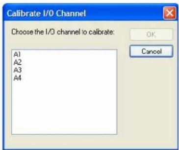
text_image
Calibrate I/O Channel Choose the I/O channel to calibrate: A1 A2 A3 A4 OK CancelSelect the channel you want to calibrate. This example uses an A4 model that has channel A1 set to Current with a Range of 0 to 20mA.
If you have not disabled confirmation messages (Tools, Options in DeviceManager only), you will get prompted to verify channel calibration.
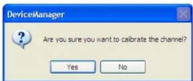
text_image
DeviceManager Are you sure you want to calibrate the channel? Yes NoClick Yes to proceed with calibration. You are now prompted to apply 0 mA to the positive (+) and negative (-) terminals. Once that is done, click Yes to proceed.
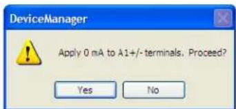
text_image
DeviceManager Apply 0 mA to A1+/- terminals. Proceed? Yes NoYou are now prompted to apply 20 mA to the positive (+) and negative (-) terminals. Once that is done, click Yes to proceed.
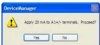
text_image
DeviceManager Apply 20 mA to A1+/- terminals. Proceed? Yes NoOnce calibration is successfully completed, click OK to finish the process.
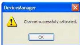
text_image
DeviceManager Channel successfully calibrated. OKResetting Calibration Data
You can reset the I/O channels calibrations to the factory calibrations in DeviceManager by selecting Tools, I/O Channels, Reset Calibrate Data or in WebManager by selecting Administration, Reset, I/O Calibration.
Setting the IOLAN's Date and Time
When you set the IOLAN's time, the connection method and time zone settings can affect the actual internal clock time that is being set. For example, if you are connecting to the IOLAN through the DeviceManager and your PC's time zone is set to Pacific Standard Time (GMT -8:00) and the IOLAN's time zone is set to Eastern Standard Time (GMT -5:00), the IOLAN's time is actually three hours ahead of your PC's time. Therefore, if you set the IOLAN's time to 2:30 pm in the DeviceManager, the IOLAN's actual internal clock time is 5:30 pm. This is the only configuration method that interprets the time and converts it between time zones, as necessary.
All other configuration methods set the IOLAN's internal clock time to the time specified, with no interpretation.
To set the IOLAN's system clock in DeviceManager, select Tools, Advanced, Set Unit Time/Date and in WebManager select Administration, Date/Time. The Set Date/Time window is displayed.
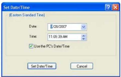
text_image
Set Date/Time (Eastern Standard Time) Date: 20/2007 Time: 11:09:39 AM Use the PC's Date/Time Set Date/Time CancelConfigure the following parameters:
| Date | The IOLAN’s date. The format of the IOLAN’s date is dependent on the Windows operating system and regional settings. |
| Time | The IOLAN’s internal clock time, based on your PC’s time zone. For example, if your PC’s time zone is set to Pacific Standard Time (GMT -8:00) and the IOLAN’s time zone is set to Eastern Standard Time (GMT -5:00), the IOLAN’s time is three hours ahead of your PC’s time. If you set the IOLAN’s time to 2:30 pm, the IOLAN’s actual internal clock time is 5:30 pm. |
| Use the PCs Date/Time | When enabled, sets the IOLAN’s time to the PCs time.Default: EnabledThis option is unique to the DeviceManager. |
Rebooting the IOLAN
When you download any file (configuration, keys, certificates, firmware, etc.) to the IOLAN, you must reboot the IOLAN for it to take effect by selecting Tools, Reset, Reboot Server in DeviceManager and Administration, Reboot Unit in WebManager.
Resetting Serial Port Statistics
You can reset the IOLAN's serial port/s statistics back to zero.
Resetting the IOLAN to Factory Defaults
You can reset the IOLAN to its factory default configuration by selecting Tools, Reset, Reset to Factory Default in DeviceManager and Administration, Reset, Factory Defaults in WebManager.
The IOLAN will automatically reboot itself with the Perle factory default or custom factory default configuration.
Resetting the SecurlD Node Secret
If you are using SecurID external authentication, you can select Tools, Reset, Reset SecurID Node Secret in DeviceManager and Administration, Reset, SecurID Secret in WebManager to reset the node secret. You do not need to reboot the IOLAN for this to take effect, it works instantly.
Language Support
Two language files, in addition to English, are supplied on the supplemental CD, French and German. You can use any of these language files to create a translation into a language of your choice. You can download the language file (whether the language is supplied or translated) into the IOLAN and select the Language option of Custom Language or Customlang (custom language), making the Menu and CLI field labels display in the desired language.
You can view Menu or CLI in one other language only (as well as English). If you download another language file, this new language will replace the first language you downloaded.
You can revert to English at any time; the English language is stored permanently in the IOLAN and is not overwritten by your new language. Each user logged into the IOLAN can operate in either English or the downloaded language.
Loading a Supplied Language
This section describes how to download a language file using the CLI, since it is the least intuitive method. French and German language files are provided on the supplemental CD.
To load one of the supplied languages into the IOLAN, so the Menu or CLI fields appear in another language, do the following:
-
Open the supplemental CD and identify the language file, either Iolan_ds_French.txt or Iolan_ds_German.txt, or supply one of your own translated files.
-
Copy the language file to a host machine on the network; place it in the main file system or on the main hard drive.
-
Either use the TFTP/SFTP defaults in the IOLAN or, configure as necessary, TFTP/SFTP in the IOLAN.
-
In the CLI of the IOLAN, enter the host IP address and file name; for example, netload customlang 172.16.4.1 /temp/Iolan_ds_French.txt snetload customlang 172.16.4.1 /temp/Iolan_ds_French.txt
The IOLAN will download the language file via TFTP or SFTP.
In DeviceManager select Tools, Advanced, Custom Files and then select Download Custom Language File and browse to the language file. In WebManager select Administration, Custom Files and then specify the Custom Language File option and browse to the language file.
-
To set an individual user to the new language, go to the Users menu and, in the Language field select Customlang. In the CLI (only) you can set individual users or all users to the new language; see the set user * command.
-
The user will see the change of language when he/she logs out (Main Menu, Sessions Menu, Logout) and logs back into the IOLAN. If, as Admin user, you change your language setting to Customlang, you will see the text menus display in the new language when you save and exit the Change User form. Users with Level Normal can also change their display language.
If you download a new software version, you can continue to use your language unchanged; however, we recommend translating the new strings, which will be added to the end of the language file. A Reset to Factory Defaults will reload the Customlang as English.
On successful download, the Customlang in the IOLAN will be overwritten by the new language.
Translation Guidance
To help you with your translation, of supplied ASCII text language files we offer the following guidance:
- The IOLAN will support languages other than English (and the supplied German and French languages). The English language file, english.txt, displays the character length of each line at the beginning of the line. If a translated line goes over that character length, it will be displayed truncated in the Menu or CLI.
- Translate line for line, do not omit lines if you do not know the translation; leave the original untranslated text in place. Also, you must maintain the same sequential order of lines. It is a good practice to translate the file using a text editor that displays line numbers, so you can periodically verify that the line sequence has not changed from the original file (by comparing it to the original file).
- Keep all translations in quotes, otherwise the line will not display properly.
• Each line must end with a carriage return. - If a line contains only numbers, for example 38400, leave that line in place, unchanged (unless you are using a different alphabet).
Software Upgrades and Language Files
If you receive a software upgrade for the IOLAN, the language files supplied on the supplemental diskette/CD might also have been updated. We will endeavour to provide a list of those changes in another text file on the same supplemental CD.
Note: The upgrade of your software (firmware) will not change the display of the language in the Menu or CLI.
If you are already using one of the supplied languages, French or German, you probably want to update the language file in the IOLAN. Until you update the IOLAN with the new language file, new text strings will appear in English.
If you are already using a language translated from an earlier version, you probably want to amend your translation. When a language file is updated, we will try to maintain the following convention:
- New text strings will be added to the bottom of the file (not inserted into the body of the existing file).
- Existing text strings, if altered, will be altered in sequence; that is, in their current position in the file.
- The existing sequence of lines will be unchanged.
- Until you have the changes translated, new text strings will appear in the Menu or CLI in English.
Downloading Terminal Definitions
All terminal types can be used on the IOLAN. Some terminal types which are not already defined in the IOLAN, however, are unable to use Full Screen mode (menus) and may not be able to page through sessions properly. When installed, the IOLAN has several defined terminal types—Dumb, WYSE60, VT100, ANSI, TV1925, IBM3151, VT320-7, and HP700/44.
If you are not using, or cannot emulate, any of these terminal types, you can add up to three additional terminal definitions to the IOLAN. The terminal definitions can be downloaded from a TCP/IP host.
To download terminal definitions, follow these steps:
- Decide which TCP/IP host you are going to use. It must be a machine with enabled.
- Configure SFTP/TFTP in the IOLAN as necessary.
- Select Tools, Advanced, Custom Files from the menu bar in DeviceManager and Administration, Custom Files in WebManager.
- From the File Type drop-down, select Download Terminal Definition. Select the terminal definition option 1, 2, or 3 and then browse to the terminal definition file that is being downloaded to the IOLAN.
- In the Terminal profile, select the Terminal Type Termx that you custom defined.
Creating Terminal Definition Files
To create new terminal definition files, you need to copy and edit the information from the termininfo database.
- On a UNIX host, change directory to /usr/lib/terminfo/x (where x is the first letter of the required terminal type). For a Wyse60, for example, you would enter the command cd /usr/lib/terminfo/w.
- The termcap files are compiled, so use the command infocmp termfile to read the required file (for example: infocmp wy60).
- Check the file for the attribute xmc#n (where n is greater than or equal to 1). This attribute will corrupt menu and form displays making the terminal type unsuitable for using Menu mode.
- If the terminal definition is suitable, change to a directory of your choice.
- Rename and copy the file to the directory specified at step 4. using the command infocmp termfile > termn where n is greater than or equal to 1; (for example, infocmp wy50 > term1). Make sure the file has global read and execute permission for its entire path.
- Edit the file to include the following capabilities in this format:
term=
acsc=
bold=
civis=
clear=
cnorm=
cup=
rev=
rmacs=
rmso=
smacs=
smso=
page=
circ=
For example:
term=AT386 | at386| 386AT |386at |at/386 console
acsc=jYk?1Zm@qDtCu4x3
bold=\E[1m
civis=
clear=\E[2J\E[H
cnorm=
cup=\E[%i%p1%02d;%p2%02dH
rev=\E4A
rmacs=\E[10m
rmso=\E[m
smacs=\E[12m
smso=\E[7m
page=
circ=n
As you can see from the example, capabilities which are not defined in the termininfo file must still be included (albeit with no value). Each entry has an 80 character limit.
On some versions of UNIX, some of the capabilities are appended with a millisecond delay (of the form
The ‘acsc’ capability, if defined, contains a list of character pairs. These pairs map the characters used by the terminal for graphics characters to those of the standard (VT100) character set.
Include only the following character pairs:
jx, kx, lx, mx, qx, tx, ux and xx
(where x must be substituted by the character used by the terminal). These are the box-drawing characters used to display the forms and menus of Menu mode. They must be entered in this order.
The last two capabilities will not be found in the termininfo file. In the page field you must enter the escape sequence used by the terminal to change screens. The circ field defines whether the terminal can use previous page and next page control sequences. It must be set to y or n. These capabilities can be found in the documentation supplied with the terminal.
Resetting Configuration Parameters
You can reset the IOLAN to its factory default settings (this will reset it to the Perle factory default or custom factory default settings, depending on what has been configured) through any of the following methods:
- You can push in the recessed button at the back of the IOLAN hardware for three to ten seconds (pushing it in and then quickly releasing will just reboot the IOLAN)
● DeviceManager, select Tools, Reset, Reset to Factory Defaults - CLI, at the command line type, reset factory
WebManager, select Administration, Reset, Factory Default, and then click the Reset to Factory Defaults button - Menu, select Network Configuration, Reset to Factory Defaults
SNMP, in the adminInfo folder, Set the adminFunction variable to 2
Lost admin Password
If the admin user password is lost, there are only two possible ways to recover it:
- reset the IOLAN to the factory defaults
- have another user that has Admin level rights, if one is already configured, reset the admin password

text_image
16Applications
Introduction
This chapter provides examples of how to integrate the IOLAN within different network environments or applications. Each scenario provides an example of a typical setup and describes the configuration steps to achieve the IOLAN functionality feature.
Configuring Modbus
This sections provides a brief overview of the steps required to configure the IOLAN for your Modbus environment. You can read the Modbus Gateway Settings and Modbus Serial Port Settings sections for more specific information about the Modbus settings.
Overview
This section describes the high-level steps required to configure the IOLAN as a Modbus Master or Slave Gateway.
Configuring a Master Gateway
To configure a Master Gateway (Modbus Master connected to the serial side of the IOLAN), do the following:
- Set the serial port that is connected to the serial Modbus Master to the Modbus Gateway profile.
- In the Modbus Gateway profile on the General tab, set the Mode to Modbus Master.
- Still on the General tab, click the Destination Slave IP Mappings button to map the Modbus Slave's IP addresses and their UIDs that the serial Modbus Master will attempt to communicate with.
- For specialized configuration options, select the Advanced tab and configure as required.
Configuring a Slave Gateway
To configure a Slave Gateway (Modbus Master resides on the TCP/Ethernet network), do the following:
- Set the serial port that is connected to the serial Modbus Slave(s) to the Modbus Gateway profile.
- In the Modbus Gateway profile on the General tab, set the Mode to Modbus Slave.
- Still on the General tab, specify the Modbus Slave UIDs that the TCP Modbus Master will attempt to communicate with.
- Still on the General tab, click the Advanced Slave Settings button to configure global Slave Gateway settings.
- For specialized configuration options, select the Advanced tab and configure as required.
Modbus Gateway Settings
The scenarios in this section are used to illustrate how the IOLAN's Modbus Gateway settings are incorporated into a Modbus device environment. Depending on how your Modbus Master or Slave devices are distributed, the IOLAN can act as both a Slave and Master Gateway(s) on a multiport IOLAN or as either a Slave or Master Gateway on a single port IOLAN.
Modbus Master Gateway
The IOLAN acts as a Master Gateway when the Modbus Master is connected to a serial port on the IOLAN. Each Modbus Master can communicate to UIDs 1-247.
Modbus Slave

flowchart
graph LR
    A["Modbus Slave"] -->|TCP| B["Network"]
    C["Modbus Master"] --> D["Modbus Slave"]
    B --> E["Master Gateway"]
    D --> F["Modbus Master"]
    E --> G["IOLAN"]
    F --> H["EIA-422/485"]
    G --> I["Serial EIA-232"]
    H --> I
    I --> J["Modbus Master"]
Modbus Slave Gateway
The IOLAN acts as a Slave Gateway when the Modbus Master resides on the TCP/Ethernet network and the Modbus Slaves are connected to the serial ports on the IOLAN. Note: The IOLAN provides a single gateway to the network-attached Modbus Masters. This means that all Modbus Slaves attached to the IOLAN's serial ports must have a unique UID. Multiple Masters on the network can communicate with these Modbus Slaves. Note: If a transaction is in progress to a Modbus Slave, other requests to that same device will be queued until that transaction is complete.
Modbus Master
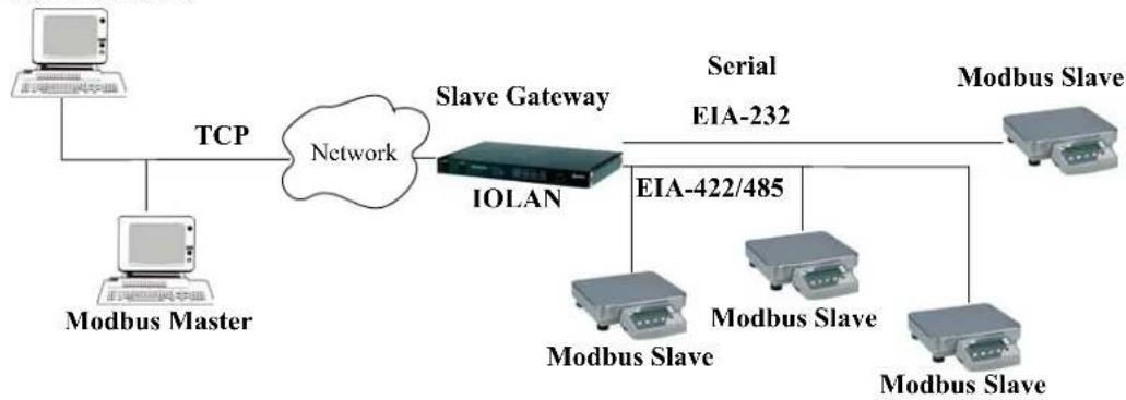
flowchart
graph LR
    A["Modbus Master"] -->|TCP| B["Network"]
    C["Modbus Master"] -->|TCP| B
    B --> D["Slave Gateway IOLAN"]
    D --> E["Serial EIA-232"]
    E --> F["Modbus Slave"]
    E --> G["Modbus Slave"]
    E --> H["Modbus Slave"]
    D --> I["EIA-422/485"]
Modbus Serial Port Settings
Modbus Master Settings
When the Modbus Masters is attached to the IOLAN's serial port, configure that serial port to the Modbus Gateway profile acting as a Modbus Master. You must configure the Modbus TCP Slaves on the TCP/Ethernet side so the IOLAN can properly route messages, using the Modbus Slave's UIDs, to the appropriate TCP-attached devices.
Modbus Slave
IP: 10.10.10.12
UID: 23
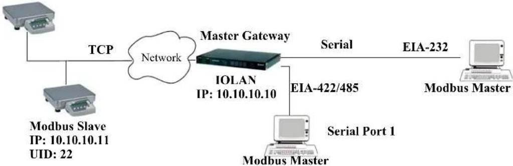
flowchart
graph LR
    A["Modbus Slave<br>IP: 10.10.10.11<br>UID: 22"] -->|TCP| B["Network"]
    C["Modbus Master"] -->|Serial Port 1| D["IOLAN<br>IP: 10.10.10.10"]
    D -->|EIA-422/485| E["Modbus Master"]
    D -->|Serial| F["EIA-232"]
    B --> G["Master Gateway"]
To configure the Modbus Master on serial port 1, do the following:
-
Select the Modbus Gateway profile for serial port 1.
-
On the General tab, enable the Modbus Master parameter.
-
Click the Destination Slave IP Mappings button and click the Add button in the Destination Slave IP Mappings window.
-
Configure the Destination Slave IP Mappings window as follows:
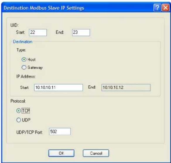
text_image
Destination Modbus Slave IP Settings UID: Start: 22 End: 23 Destination Type: Host Gateway IP Address: Start: 10.10.10.11 End: 10.10.10.12 Protocol: TCP UDP UDP/TCP Port: 502 OK CancelThe IOLAN will send a request and expect a response from the Modbus Slave with an IP Address of 10.10.10.11 on Port 502 with UID 22 and from the Modbus Slave with and IP Address of 10.10.10.12 on Port 502 with UID 23 (remember when Type is set to Host, the IOLAN increments the last octet of the IP address for each UID specified in the range).
Modbus Slave Settings
When you have Modbus Slaves on the serial side of the IOLAN, configure the serial port to the Modbus Gateway profile acting as a Modbus Slave. There is only one Slave Gateway in the IOLAN, so all Modbus serial Slaves must be configured uniquely for that one Slave Gateway; all serial Modbus Slaves must have unique UIDs, even if they reside on different serial ports, because they all must be configured to communicate through the one Slave Gateway.
Modbus Master
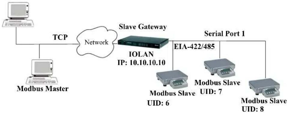
flowchart
graph TD
    A["Modbus Master"] -->|TCP| B["IOLAN IP: 10.10.10.10"]
    C["Modbus Master"] --> D["Modbus Slave"]
    D --> E["EIA-422/485"]
    B --> F["Serial Port 1"]
    B --> G["Serial Port 1"]
    B --> H["Serial Port 1"]
    B --> I["Serial Port 1"]
    B --> J["Serial Port 1"]
    B --> K["Serial Port 1"]
    B --> L["Serial Port 1"]
To configure the Modbus Gateway on serial port 1, do the following:
- Select the Modbus Gateway profile for serial port 1.
- On the General tab, enable the Modbus Slave parameter.
- Still on the General tab, specify the UID Range as 6-8 as shown below:
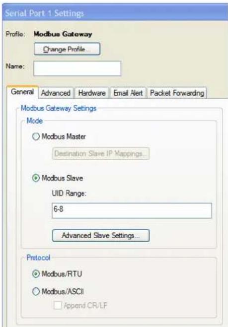
text_image
Serial Part 1 Settings Profile: Modbus Gateway Change Profile... Name: General Advanced Hardware Email Alert Packet Forwarding Modbus Gateway Settings Mode Modbus Master Destination Slave IP Mappings... Modbus Slave UID Range: 6-8 Advanced Slave Settings... Protocol Modbus/RTU Modbus/ASCII Append CR/LF- Click the Advanced Slave Settings button to verify that the default settings are acceptable.
Configuring PPP Dial On Demand
The IOLAN can be configured to access remote networks via modems connected to the serial interface of the IOLAN. By configuring the IOLAN for the Remote Access (PPP) profile, data that is destined for the remote network will initiate a modem connection to the remote network to route the data to its appropriate destination.
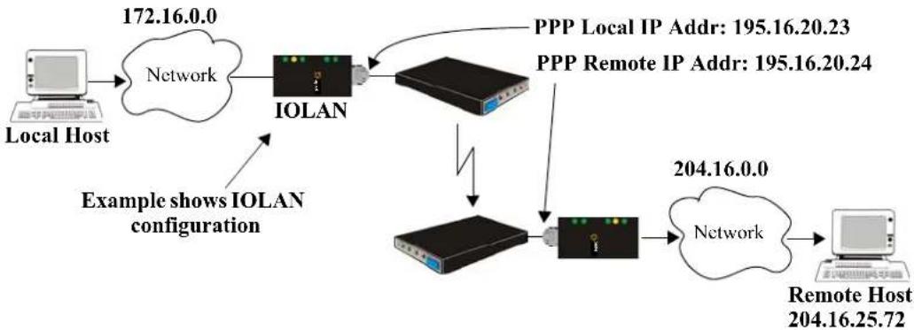
flowchart
graph TD
    A["Local Host"] --> B["Network 172.16.0.0"]
    B --> C["IOLAN"]
    C --> D["PPP Local IP Addr: 195.16.20.23"]
    C --> E["PPP Remote IP Addr: 195.16.20.24"]
    C --> F["Network 204.16.0.0"]
    F --> G["Remote Host 204.16.25.72"]
    H["Example shows IOLAN configuration"] --> C
If you want to configure a serial port to use PPP dial on demand, do the following:
- Create an entry for the modem and its initialization string (Serial, Advanced, Modems tab).
- Set the serial port to Remote Access (PPP).
- In Remote Access (PPP), select the Advanced tab. Enable the Connect option and select Dial Out. Set the Modem parameter to the modem you just added. Enter the Phone number that the modem will be calling.
- Still on the Advanced tab, set the Idle Timeout parameter to a value that is not zero (setting this value to zero creates a permanent connection).
- On the General tab, enter one of the following:
• A Local and/or Remote IPv4 Address
• A Local and/or Remote IPv6 Interface Identifier
Note that this IP address or interface identifier should be on its own unique network; that is, not part of the local or remote networks.
In this example, the local network has an IPv4 address of 172.16.0.0/16 and the remote network has an IPv4 address of 204.16.0.0/16, so we arbitrarily assigned the PPP IPv4 Local IP Address as 195.16.20.23 and the PPP IPv4 Remote IP Address as 195.16.20.24.
| IPv4 Local IP Address: | 195 . 16 . 20 . 23 |
| IPv4 Remote IP Address. | 195 . 16 . 20 . 24 |
| IPv4 Subnet Mask: | 255 . 255 . 255 . 0 |
- Next you need to create a gateway and destination route entry. Select Network, Advanced, and the Route List tab.
For the destination, if you want the connection to be able to reach any host in the remote network, set the Type to Network and specify the network IP address and subnet/prefix bits; if you want the connection to go directly to a specific remote host, set the Type to Host and specify the host's IP address.
We want a specific host to the be destination, so we configured the Type as Host:
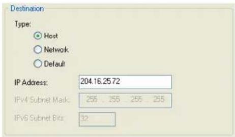
text_image
Destination Type: Host Network Default IP Address: 204.16.25.72 IPv4 Subnet Mask: 255 255 255 255 IPv6 Subnet Bits: 32We also need to create a Gateway entry using the same PPP IPv4 local IP address. Any traffic that goes through the gateway will automatically cause PPP to dial out:
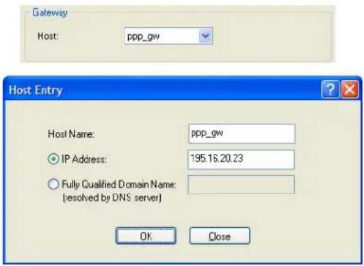
text_image
Gateway Host: ppp_gw Host Entry Host Name: ppp_gw IP Address: 195.16.20.23 Fully Qualified Domain Name: (resolved by DNS server) OK CloseSetting Up Printers
The IOLAN can communicate with printers on its serial ports using LPD and RCP protocols, as well as print handling software using TCP/IP.
Remote Printing Using LPD
When setting up a serial line that access a printer using LPD, do the following:
-
Set the serial port to Printer and configure the Speed, Flow Control, Stop Bits, Parity, and Bits parameters so that they match the printer's port settings.
-
Save your settings and restart the serial port.
-
Verify that LPD has been configured on the network host. To configure LPD on the network host, you need to know the name or IP address of the IOLAN and the print queue, either raw_p
for an ASCII character connection. If you want to direct output to a hunt group, omit the port number(s). For example: raw_p or ascii_p. You can optionally append_d or_f to the queue name to add a or -
To execute a print job on a UNIX Linux system, use the following syntax:
lp -d raw_p
Remote Printing Using RCP
When setting up a serial port that accesses a printer using RCP, do the following:
- Set the serial port to Printer and configure the Speed, Flow Control, Stop Bits, Parity, and Bits parameters so that they match the printer's port settings.
- Save your settings and restart the serial port.
- To execute a print job, use either of the following syntaxes:
rcp <filename> <ip_address>:<line_name>
or
rcp <filename> <IOLAN_Name><line_name>
where <#> is the IOLAN serial port number.
Remote Printing Using Host-Based Print Handling Software
Printers connected to the IOLAN can be accessed by TCP/IP hosts using print handling software.
- Set the serial port to TCP Sockets. Enable the Listen for connection option. On the Hardware tab, configure the Speed, Flow Control, Stop Bits, Parity, and Bits parameters so that they match the printer's port settings.
- Save your settings and restart the serial port.
- The print handling software needs to know the Name of the IOLAN and the TCP Port number assigned to the printer serial port.
Configuring a Virtual Private Network
You can configure the IOLAN to act as a Virtual Private Network (VPN) gateway using the IPsec protocol. Any of the following scenarios can be configured using one IOLAN and a host/server running IPsec software or two IOLANs, each acting as the VPN gateway. All the examples have NAT Traversal (NAT_T) enabled, since both VPN gateways are running through routers.
IOLAN-to-Host/Network
The following example shows how to configure an IPsec tunnel between serial devices connected to the IOLAN and a host/network. NAT Traversal (NAT_T) is enabled in this example (on both sides) because the VPN tunnel is going private network to public network to private network. This example uses an RSA signature for the authentication method, so the steps required to configure the authentication are in this example.
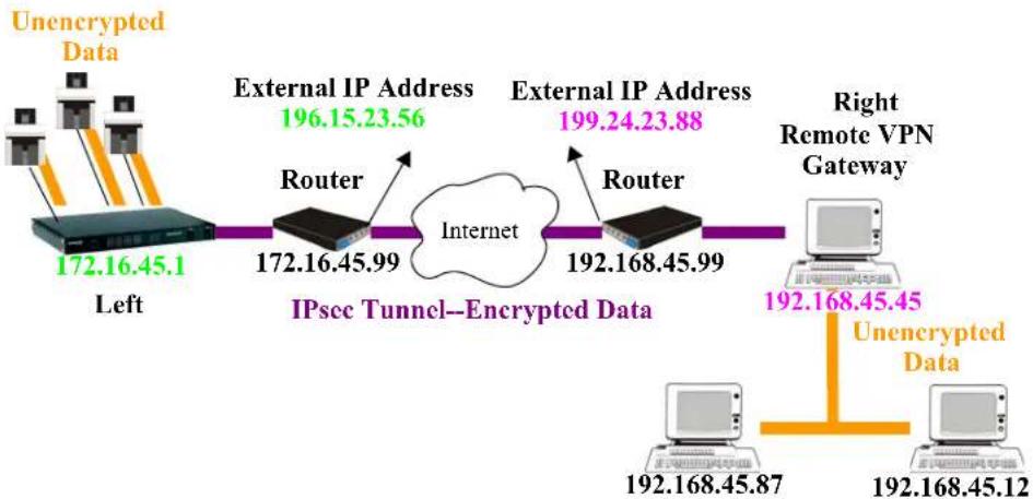
flowchart
graph LR
    A["Unencrypted Data"] --> B["172.16.45.1 Left"]
    B --> C["Router 172.16.45.99"]
    C --> D["IPsec Tunnel—Encrypted Data"]
    D --> E["Router 192.168.45.99"]
    E --> F["Right Remote VPN Gateway"]
    F --> G["192.168.45.45 Unencrypted Data"]
    G --> H["192.168.45.87"]
    G --> I["192.168.45.12"]
    style A fill:#f9f,stroke:#333
    style B fill:#ccf,stroke:#333
    style C fill:#cfc,stroke:#333
    style D fill:#fcc,stroke:#333
    style E fill:#cff,stroke:#333
    style F fill:#ffc,stroke:#333
    style G fill:#f9f,stroke:#333
    style H fill:#ccf,stroke:#333
    style I fill:#cfc,stroke:#333
- Configure the IPsec tunnel in the IOLAN:
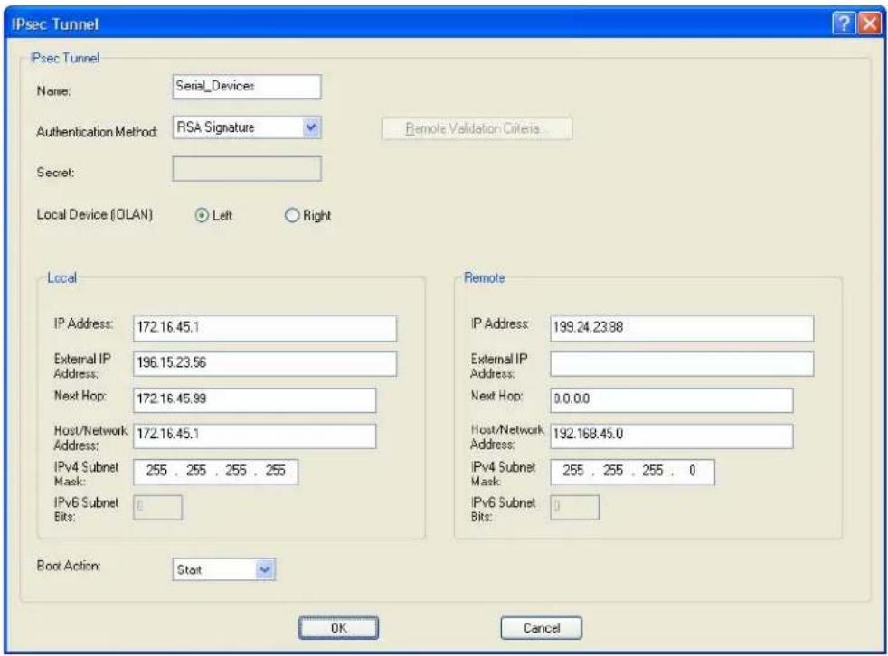
text_image
IPsec Tunnel IPsec Tunnel Name: Serial_Devices Authentication Method: RSA Signature Secret: Local Device (OLAN) Left Right Local IP Address: 172.16.45.1 External IP Address: 196.15.23.56 Next Hop: 172.16.45.99 Host/Network Address: 172.16.45.1 IPv4 Subnet Mask: 255 . 255 . 255 . 255 IPv6 Subnet Bits: 0 Boot Action: Start Remote IP Address: 199.24.23.88 External IP Address: Next Hop: 0.0.0.0 Host/Network Address: 192.168.45.0 IPv4 Subnet Mask: 255 . 255 . 255 . 0 IPv6 Subnet Bits: 0 OK Cancel- Use a utility (for example, Openswan's newhostkey/showhostkey utilities) to generate the RSA signature public key for the Remote VPN gateway. Copy the public key portion to a file using the following format:
<description>=<keydata>
or just
<keydata>
For example:
<h1 id="rsa-1024-bits-scs48_vpn-tue-jan-3-152933-2006">RSA 1024 bits scs48_vpn Tue Jan 3 15:29:33 2006</h1>
leftrsasigkey=0sAQOEmzSTdNv1ZUJW9UmPtUY84gM5AGEAOq9gUwFqnOUsESfnuXlxPe+Mc+uf
XYvg1vxYZ0XhdIh1FwFeeIQLyRvD447mjriMFjJfheMUtHqOZhvWSE18ZfGEXNOo7yagZqLzjxu9
XJIA2SAGV+/LL3epPqW2fV5ORxVrf7uWn7I5FQ==
Note that the pound sign (#) indicates a comment line and all characters in that line are ignored. The key value itself should not have an carriage returns.
- In the DeviceManager, select Tools, Advanced, Keys and Certificates. In the WebManager, select Tools, Administration, Keys/Certificates. Download the RSA signature public file (for the Remote VPN Gateway) to the DeviceManager, specifying the IPsec tunnel it's for:
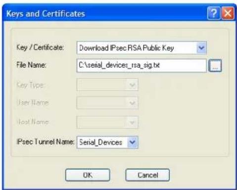
text_image
Keys and Certificates Key / Certificate: Download IPsec RSA Public Key File Name: C:\serial_devices_rsa_sig.txt Key Type: User Name: Host Name: IPsec Tunnel Name: Serial_Devices OK Cancel- In the same Keys and Certificates window, upload the IOLAN's RSA signature public key:
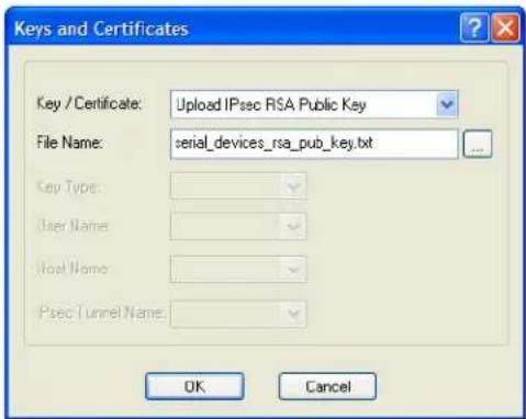
text_image
Keys and Certificates Key / Certificate: Upload IPsec RSA Public Key File Name: serial_devices_rsa_pub_key.txt Key Type: User Name: Host Name: Psec Tunnel Name: OK CancelInstall the IOLAN's public key in the remote VPN gateway for the Serial_Devices IPsec tunnel.
- Enable the IPsec service found in Security, Services.
Network-to-Network
The following examples shows how to configure a network-to-network IPsec tunnel. This example uses the X.509 Certificate authentication method, so it includes the configuration requirements for the X.509 certificate. NAT Traversal (NAT_T) is enabled in this example (on both sides) because the VPN tunnel is going private network to public network to private network. Notice also that the serial devices connected to the IOLAN can be accessed by the VPN tunnel, since they are included in the network configuration as part of the 172.16.45.0 subnetwork.
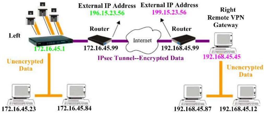
flowchart
graph LR
    A["Left"] --> B["172.16.45.1"]
    B --> C["Router 172.16.45.99"]
    C --> D["IPsec Tunnel--Encrypted Data"]
    D --> E["Router 192.168.45.99"]
    E --> F["Right Remote VPN Gateway"]
    G["Unencrypted Data"] --> H["172.16.45.23"]
    I["Unencrypted Data"] --> J["172.16.45.84"]
    K["External IP Address 196.15.23.56"] --> C
    L["External IP Address 199.15.23.56"] --> E
    M["Internet"] --> D
    N["192.168.45.87"] --> F
    O["192.168.45.12"] --> J
- Configure the IPsec tunnel in the IOLAN:
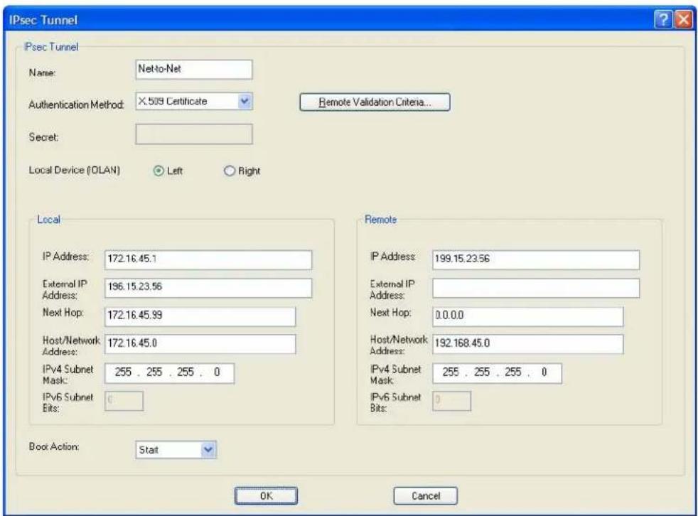
text_image
IPsec Tunnel Psec Tunnel Name: Netto-Net Authentication Method: X.509 Certificate Secret: Local Device (OLAN) Left Right Local IP Address: 172.16.45.1 External IP Address: 196.15.23.56 Next Hop: 172.16.45.99 Host/Network Address: 172.16.45.0 IPv4 Subnet Mask: 255 . 255 . 255 . 0 IPv6 Subnet Bits: 0 Boot Action: Start Remote IP Address: 199.15.23.56 External IP Address: Next Hop: 0.0.0.0 Host/Network Address: 192.168.45.0 IPv4 Subnet Mask: 255 . 255 . 255 . 0 IPv6 Subnet Bits: 0 OK Cancel-
Click the Remote Validation Criteria button and enable and populate the fields that are required for the remote X.509 certificate validation. If you just want to validate the X.509 certificate signer, you do not need to enable any of the remote validation criteria fields.
-
If the signer of the remote X.509 certificate has not already been included in the CA list file that has already been downloaded to the IOLAN, you need to add (append) the signer of the X.509 certificate to the CA list file and then download the file to the IOLAN by selecting Tools, Advanced, Keys and Certificates. In the Keys and Certificates window, select Download SSL/TLS CA and the file name and click OK. Note that this file must be a concatenation of all certificate signers required for any SSL/TLS, LDAP, SSH, and/or IPsec connections.
-
Enable the IPsec service found in Security, Services.
Host-to-Host
The following example shows how to configure two IOLANs to work as VPN gateways for a host-to-host IPsec tunnel. NAT Traversal (NAT_T) is enabled in this example (on both sides) because the VPN tunnel is going private network to public network to private network. In this example, both of the IOLAN VPN gateways have a DHCP assigned IP address.
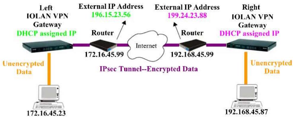
flowchart
graph LR
    A["Left IOLAN VPN Gateway DHCP assigned IP"] --> B["Router"]
    B --> C["IPsec Tunnel--Encrypted Data"]
    C --> D["Router"]
    D --> E["Right IOLAN VPN Gateway DHCP assigned IP"]
    F["Unencrypted Data"] --> G["172.16.45.23"]
    H["External IP Address 196.15.23.56"] --> B
    I["External IP Address 199.24.23.88"] --> D
    J["Unencrypted Data"] --> K["192.168.45.87"]
- The following window configures the Left IOLAN VPN Gateway:
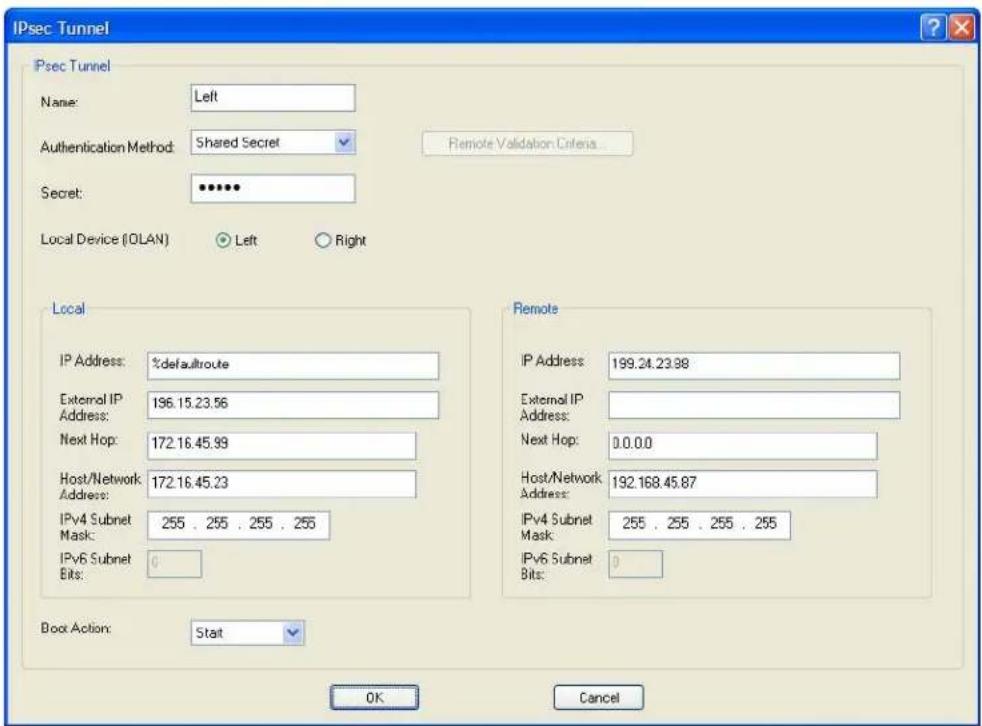
text_image
IPsec Tunnel Psec Tunnel Name: Left Authentication Method: Shared Secret Secret: •••••• Local Device (OLAN) Left Right Local IP Address: %defaultroute External IP Address: 196.15.23.56 Next Hop: 172.16.45.99 Host/Network Address: 172.16.45.23 IPv4 Subnet Mask: 255 . 255 . 255 . 255 IPv6 Subnet Bits: Boot Action: Start Remote IP Address: 199.24.23.88 External IP Address: Next Hop: 0.0.00 Host/Network Address: 192.168.45.87 IPv4 Subnet Mask: 255 . 255 . 255 . 255 IPv6 Subnet Bits: OK Cancel%defaultroute is entered for the Local IP Address because the IP address is DHCP assigned and is therefore subject to change.
- The following window configures the Right IOLAN VPN Gateway:
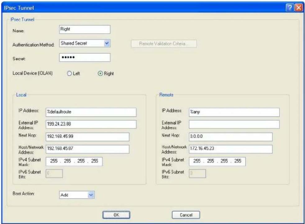
text_image
IPsec Tunnel IPsec Tunnel Name: Right Authentication Method: Shared Secret Secret: •••••• Local Device (OLAN) Left Right Local IP Address: %defaultroute External IP Address: 199.24.23.88 Next Hop: 192.168.45.99 Host/Network Address: 192.168.45.87 IPv4 Subnet Mask: 255 . 255 . 255 . 255 IPv6 Subnet Bits: 0 Boot Action: Add Remote IP Address: %any External IP Address: Next Hop: 0.0.0.0 Host/Network Address: 172.16.45.23 IPv4 Subnet Mask: 255 . 255 . 255 . 255 IPv6 Subnet Bits: 0 OK Cancel%defaultroute is entered for the Local IP Address because the IP address is DHCP assigned and is therefore subject to change.
%any is entered for the Remote IP Address to indicate that it will accept a VPN connection from any host/network; this is necessary because the Left IOLAN VPN gateway is DHCP assigned and cannot be known.
Also note that Boot Action on the Left IOLAN VPN gateway is set to Start, meaning that it will try to initiate the VPN connection, while the Boot Action on the Right IOLAN VPN gateway is set to Add, which will listen for a VPN connection request.
- Enable the IPsec service found in Security, Services.
VPN Client-to-Network
The following example shows how to configure a VPN client-to-network IPsec tunnel. In this example, the IOLAN will accept VPN connections from multiple VPN clients on private networks that want to access the public 199.24.0.0 subnetwork through the VPN gateway. NAT Traversal (NAT_T) is disabled in this example (on both sides) because the VPN tunnel is going private network to public network.
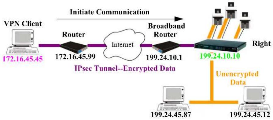
flowchart
graph LR
    A["VPN Client 172.16.45.45"] --> B["Router 172.16.45.99"]
    B --> C["Internet"]
    C --> D["Broadband Router 199.24.10.1"]
    D --> E["IPsec Tunnel--Encrypted Data"]
    E --> F["Unencrypted Data"]
    F --> G["Right 199.24.10.10"]
    G --> H["Computer 199.24.45.87"]
    G --> I["Computer 199.24.45.12"]
    style A fill:#f9f,stroke:#333
    style B fill:#ccf,stroke:#333
    style C fill:#cfc,stroke:#333
    style D fill:#fcc,stroke:#333
    style E fill:#ffc,stroke:#333
    style F fill:#cff,stroke:#333
    style G fill:#ffc,stroke:#333
    style H fill:#cfc,stroke:#333
    style I fill:#cfc,stroke:#333
Configure the IPsec tunnel in the IOLAN:
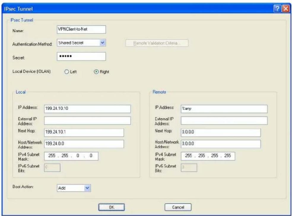
text_image
IPsec Tunnel IPsec Tunnel Name: VPNClient-to-Net Authentication Method: Shared Secret Secret: •••••• Local Device (OLAN) Left Right Local IP Address: 199.24.10.10 External IP Address: Next Hop: 199.24.10.1 Host/Network Address: 199.24.0.0 IPv4 Subnet Mask: 255 . 255 . 0 . 0 IPv6 Subnet Bits: 0 Boot Action: Add Remote IP Address: %any External IP Address: Next Hop: 0.0.0.0 Host/Network Address: 0.0.0.0 IPv4 Subnet Mask: 255 . 255 . 255 . 255 IPv6 Subnet Bits: 0 OK CancelThe Remote IP Address field is set to any to allow any VPN client to communicate in the IPsec tunnel that can validate the Secret. Also, the Remote Host/Network field is configured for 0.0.0.0 to allow any remote peer private IP address (RFC 1918—10.0.0.0/8, 172.16.0.0./12, 192.168.0.0/16) access to the IPsec tunnel. Lastly, the Boot Action is set to Add to listen for an IPsec tunnel connection.
Configuring HTTP Tunnels
When HTTP tunneling is used TCP and UDP ports 50000 and above are reserved and should not be configured by the user.
Serial-to Serial
The following example will demonstrate how to set up a serial device (VT100 Terminal) to serial device (Linux host, console port) connection via an HTTPS tunnel. HTTPS will be used because data security is required. Because IOLAN 1 is behind the firewall, it will need to initiate the HTTP tunnel connection.
For more HTTP tunneling configuration parameters see HTTP Tunneling
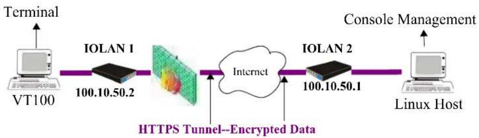
flowchart
graph LR
    A["Terminal"] --> B["VT100"]
    B --> C["IOLAN 1 100.10.50.2"]
    C --> D["HTTPS Tunnel--Encrypted Data"]
    D --> E["Internet"]
    E --> F["IOLAN 2 100.10.50.1"]
    F --> G["Console Management"]
    G --> H["Linux Host"]
Configure a "connect to" HTTP tunnel on IOLAN 1
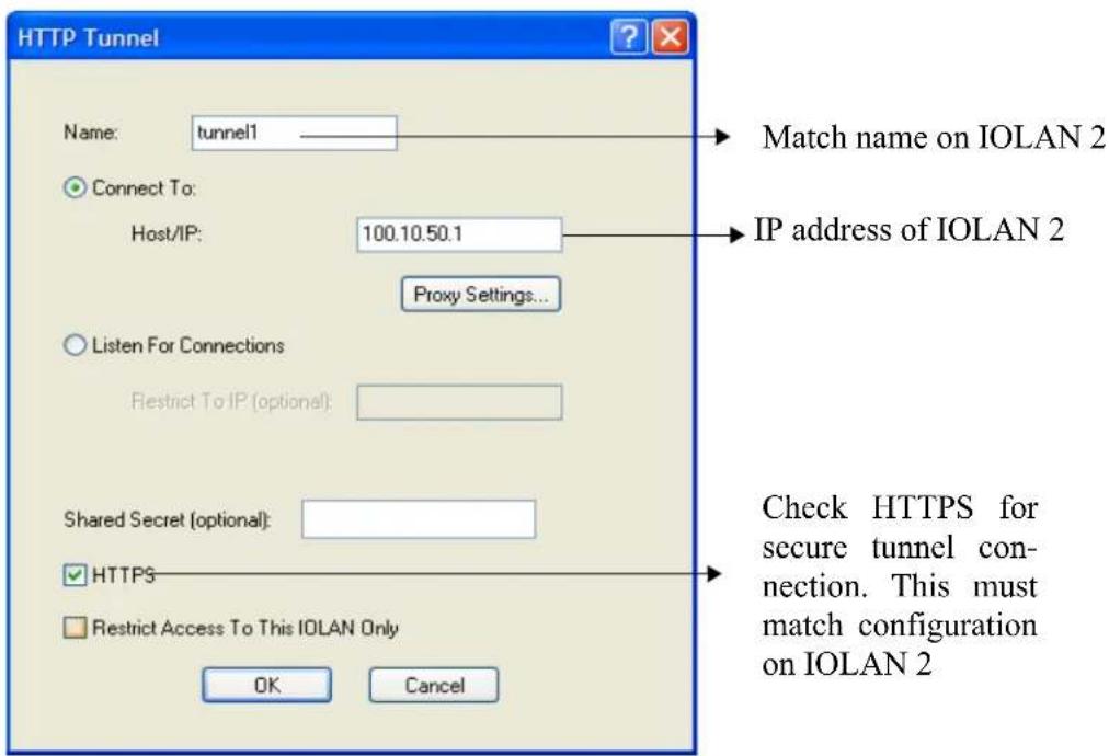
text_image
HTTP Tunnel Name: tunnel1 Connect To: Host/IP: 100.10.50.1 Proxy Settings... Listen For Connections Restrict To IP (optional): Shared Secret (optional): HTTPS Restrict Access To This IOLAN Only OK Cancel Match name on IOLAN 2 IP address of IOLAN 2 Check HTTPS for secure tunnel connection. This must match configuration on IOLAN 2Configure a "Listen for connection" HTTP tunnel on IOLAN 2
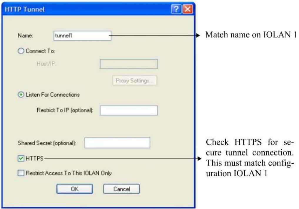
text_image
HTTP Tunnel Name: tunnel1 Connect To: Host/IP: Proxy Settings... Listen For Connections Restrict To IP (optional): Shared Secret (optional): HTTPS Restrict Access To This IOLAN Only OK Cancel Match name on IOLAN 1 Check HTTPS for secure tunnel connection. This must match configuration IOLAN 1On IOLAN 1, under Serial port configuration, select serial ports and configure for Terminal profile.
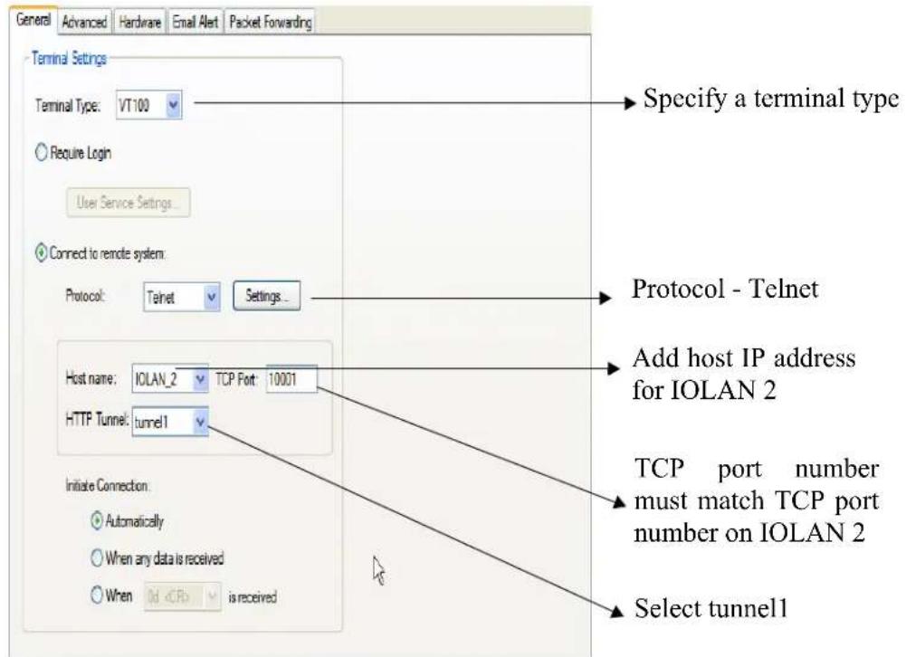
text_image
General Advanced Hardware Email Alert Packet Forwarding Terminal Settings Terminal Type: VT100 Require Login User Service Settings... Connect to remote system: Protocol: Telnet Settings... Host name: IOLAN_2 TCP Port: 10001 HTTP Tunnel: tunnel1 Initiate Connection: Automatically When any data is received WhenOn IOLAN 2, under serial port configuration, select serial port and configure for Console Management profile..
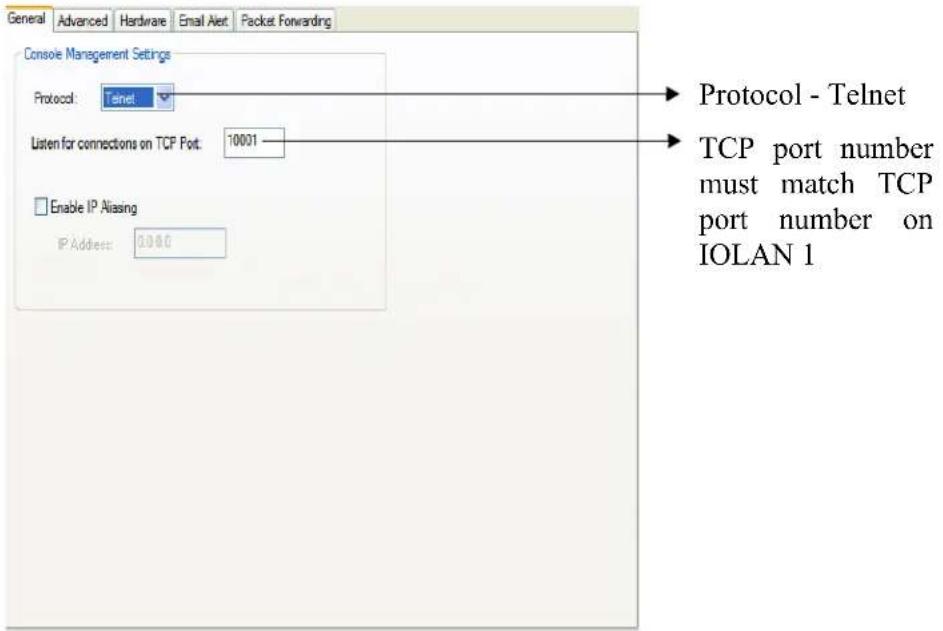
text_image
General Advanced Hardware Email Alert Packet Forwarding Console Management Settings Protocol: Telnet Listen for connections on TCP Port: 10001 Enable IP Aliasing IP Address: 0.000 Protocol - Telnet TCP port number must match TCP port number on IOLAN 1The setup for HTTP Tunnel serial-to-serial is now complete.
Serial-to Host
The following example will demonstrate how to setup a serial device (Point of Sale terminal) to an IP host (100.10.60.3) connection via an HTTP tunnel. Because IOLAN 1 is behind the firewall, it will need to initiate the tunnel connection to IOLAN 2. At the application level, the serial device will initiate the connection with the IP host.
For more HTTP tunneling configuration parameters see HTTP Tunneling
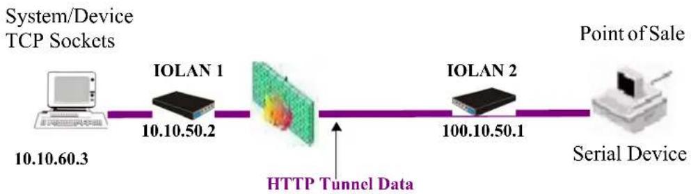
flowchart
graph LR
    A["System/Device TCP Sockets"] --> B["IOLAN 1"]
    B --> C["HTTP Tunnel Data"]
    C --> D["IOLAN 2"]
    D --> E["Serial Device"]
    style A fill:#f9f,stroke:#333
    style B fill:#ccf,stroke:#333
    style C fill:#cfc,stroke:#333
    style D fill:#fcc,stroke:#333
    style E fill:#cff,stroke:#333
Configure a "connect to" HTTP tunnel on IOLAN 1
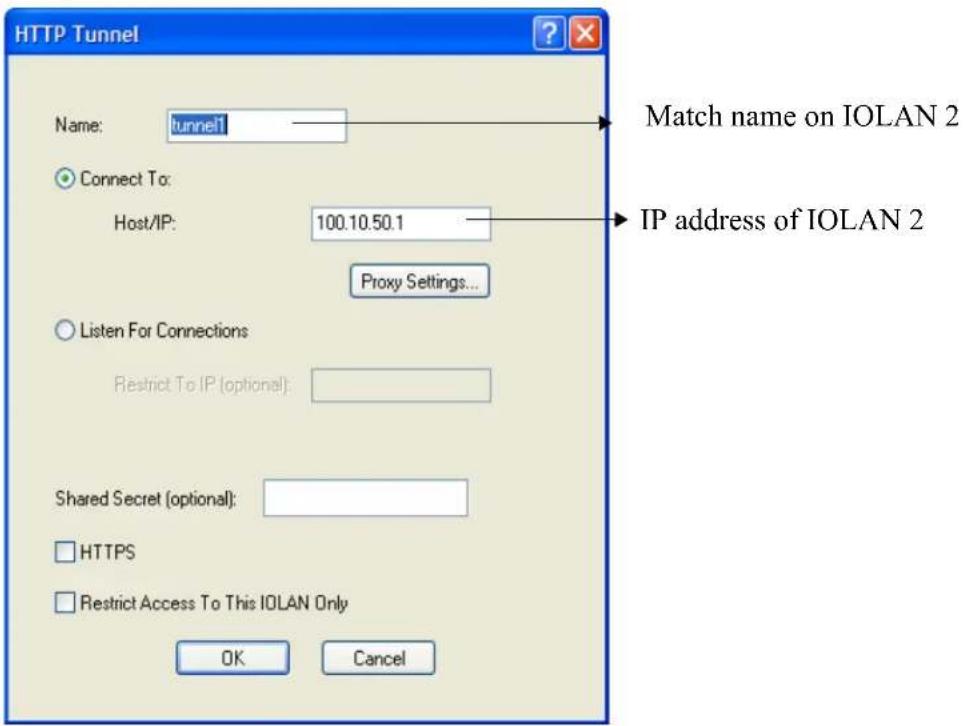
text_image
HTTP Tunnel Name: tunnel1 Connect To: Host/IP: 100.10.50.1 Proxy Settings... Listen For Connections Restrict To IP (optional): Shared Secret (optional): HTTPS Restrict Access To This IOLAN Only Match name on IOLAN 2 IP address of IOLAN 2 OK CancelConfigure a "Listen for connection" HTTP tunnel on IOLAN 2
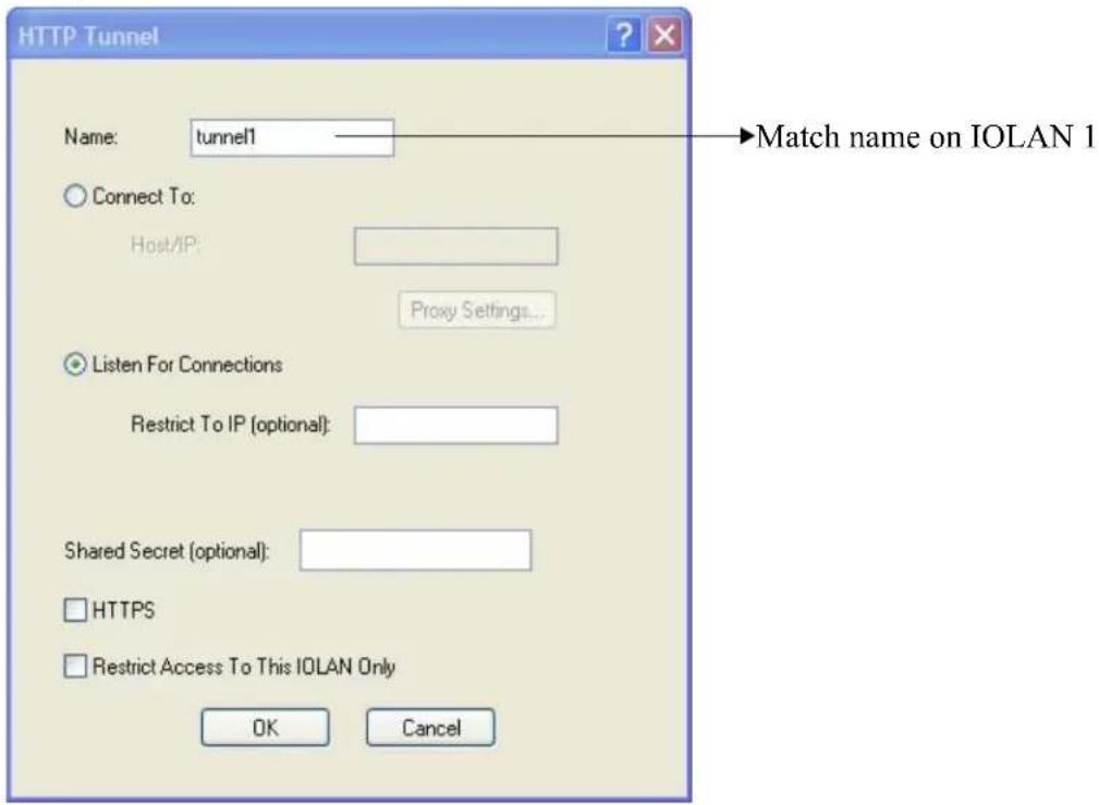
text_image
HTTP Tunnel Name: tunnel1 Connect To: Host/IP: Proxy Settings... Listen For Connections Restrict To IP (optional): Shared Secret (optional): HTTPS Restrict Access To This IOLAN Only OK Cancel Match name on IOLAN 1Add The IP host to the host table on IOLAN 2.
Configure the serial port on IOLAN 2, as follows;
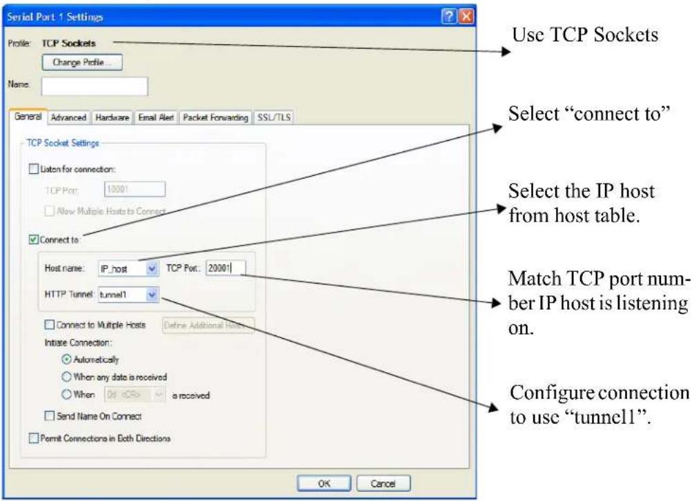
text_image
Serial Port 1 Settings Profile: TCP Sockets Change Profile... Name: General Advanced Hardware Email Alert Packet Forwarding SSL/TLS TCP Socket Settings Listen for connection: TCP Port: 10001 Allow Multiple Hosts to Connect Connect to: Host name: IP_host TCP Port: 20001 HTTP Tunnel tunnel1 Connect to Multiple Hosts Define Additional Hosts Initiate Connection: Automatically When any data is received When a received Send Name On Connect Permit Connections in Both Directions Use TCP Sockets Select "connect to" Select the IP host from host table. Match TCP port number IP host is listening on. Configure connection to use "tunnel1". OK CancelWhen IOLAN 1 boots, it will establish an HTTP tunnel to IOLAN 2.
IOLAN 2 will initiate a connection between the serial device and the IP host. The connection will use the destination TCP port 20001.
The setup for HTTP Tunnel Host-to-Serial is now complete.
Host-to Host
The following example will demonstrate how to setup an IP Host (10.10.100.2) to an IP Host (100.10.50.60) connection via an HTTP tunnel. In this example, the hosts are doing a TFTP transfer which uses the UDP protocol.
Because IOLAN 1 is behind the firewall, it will need to initiate the tunnel connection to IOLAN 2.
For more HTTP tunneling configuration parameters see HTTP Tunneling
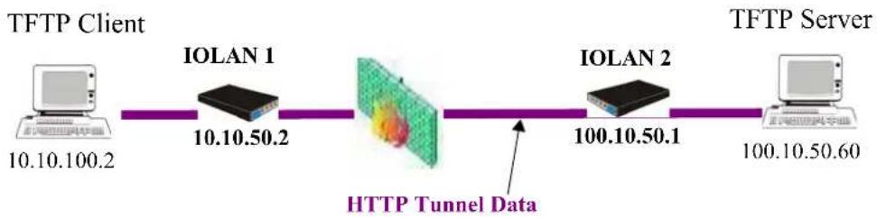
flowchart
graph LR
    A["TFTP Client\n10.10.100.2"] --> B["IOLAN 1\n10.10.50.2"]
    B --> C["HTTP Tunnel Data\n100.10.50.1"]
    C --> D["IOLAN 2\n100.10.50.1"]
    D --> E["TFTP Server\n100.10.50.60"]
Configure a "connect to" HTTP tunnel on IOLAN 1

text_image
HTTP Tunnel Name: tunnel1 Connect To: Host/IP: 100.10.50.1 Proxy Settings... Listen For Connections Restrict To IP (optional): Shared Secret (optional): HTTPS Restrict Access To This IOLAN Only Match name on IOLAN 2 IP address of IOLAN 2 OK CancelConfigure a "Listen for connection" HTTP tunnel.
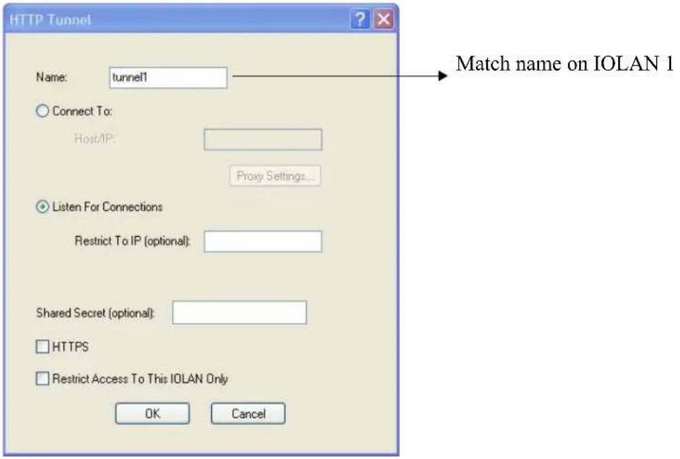
text_image
HTTP Tunnel Name: tunnel1 Connect To: Host/IP: Proxy Settings... Listen For Connections Restrict To IP (optional): Shared Secret (optional): HTTPS Restrict Access To This IOLAN Only OK Cancel Match name on IOLAN 1On IOLAN 1, under HTTP Tunnel, add a Tunnel destination.
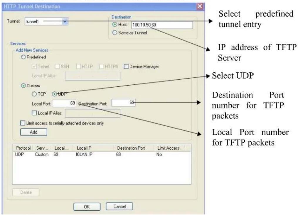
text_image
HTTP Tunnel Destination Tunnel: tunnel1 Destination Host: 100.10.50.60 Same as Tunnel Select predefined tunnel entry IP address of TFTP Server Select UDP Add New Services Predefined Telnet SSH HTTP HTTPS Device Manager Local IP Alias: Custom TCP UDP Local Port: 69 Destination Port: 69 Local IP Alias: Limit access to serially attached devices only Add Protocol Serv... Local... Local IP Destination Port Limit Access UDP Custom 69 IOLAN IP 69 No Delete OK CancelThe setup for HTTP Tunnel Host-to-Host is now complete.
Tunnel Relay
The following example will demonstrate how to setup an IP host (10.10.10.10) to an IP Host (10.10.11.11) connection using HTTP tunnels when both hosts are sitting behind a firewall. To do this, a third IOLAN which is not behind a firewall is required.
Because IOLAN 1 and IOLAN 3 are both behind a firewall, each will need to initiate a connection to IOLAN2 who is in the open.
For more HTTP tunneling configuration parameters see HTTP Tunneling
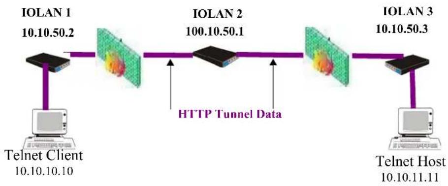
flowchart
graph LR
    A["Telnet Client 10.10.10.10"] --> B["IOLAN 1 10.10.50.2"]
    B --> C["IOLAN 2 100.10.50.1"]
    C --> D["IOLAN 3 10.10.50.3"]
    D --> E["Telnet Host 10.10.11.11"]
    C -->|HTTP Tunnel Data| C
Configure a "connect to" HTTP tunnel on IOLAN 1

text_image
HTTP Tunnel Name: tunnel Connect To: Host/IP: 100.10.50.1 Proxy Settings... Listen For Connections Restrict To IP (optional): Shared Secret (optional): HTTPS Restrict Access To This IOLAN Only Match name on IOLAN 2 IP address of IOLAN 2 OK CancelConfigure a "Listen for connection" HTTP tunnel on IOLAN 2

text_image
HTTP Tunnel Name: tunnel1 Connect To: Host/IP: Proxy Settings... Listen For Connections Restrict To IP (optional): Shared Secret (optional): HTTPS Restrict Access To This IOLAN Only OK Cancel Match name on IOLAN 1Configure a second "Listen for connection to IOLAN
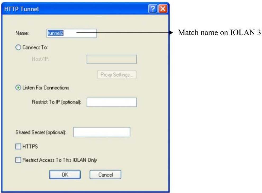
text_image
HTTP Tunnel Name: tunnel2 Connect To: Host/IP: Proxy Settings... Listen For Connections Restrict To IP (optional): Shared Secret (optional): HTTPS Restrict Access To This IOLAN Only OK Cancel Match name on IOLAN 3Configure a "connect to" HTTP tunnel on IOLAN 3
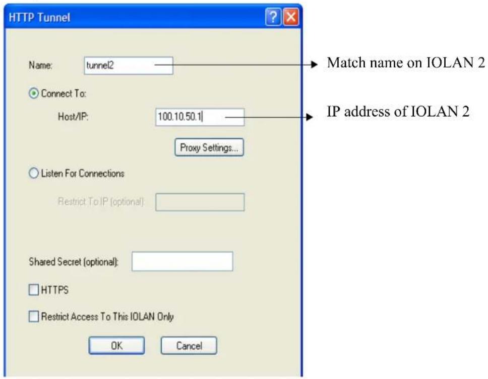
text_image
HTTP Tunnel Name: tunnel2 Connect To: Host/IP: 100.10.50.1 Proxy Settings... Listen For Connections Restrict To IP (optional): Shared Secret (optional): HTTPS Restrict Access To This IOLAN Only Match name on IOLAN 2 IP address of IOLAN 2 OK CancelOn IOLAN 1, under HTTP Tunnel, add a Tunnel destination
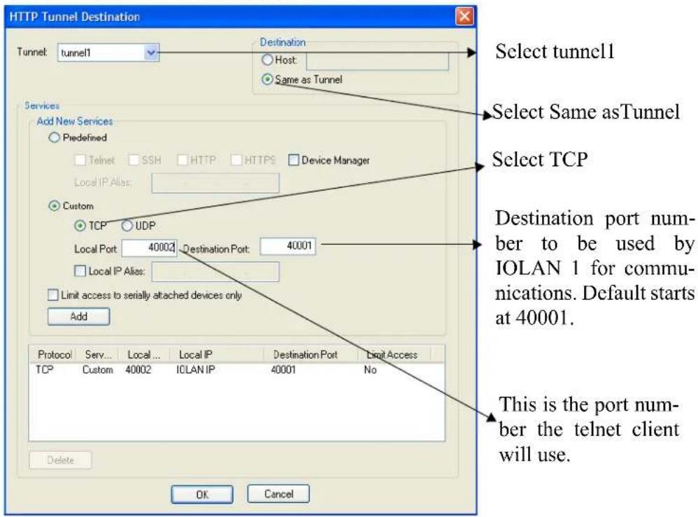
text_image
HTTP Tunnel Destination Tunnel: tunnel1 Destination Host: Same as Tunnel Select tunnel1 Select Same as Tunnel Select TCP Add New Services Predefined Telnet SSH HTTP HTTPS Device Manager Local IP Alias: Custom TCP UDP Local Port 40002 Destination Port: 40001 Local IP Alias: Limit access to serially attached devices only Add Protocol Serv... Local... Local IP Destination Port Dnuit Access TCP Custom 40002 IOLAN IP 40001 No This is the port number the telnet client will use. Delete OK CancelOn IOLAN 2, under HTTP Tunnel, add a Tunnel destination.
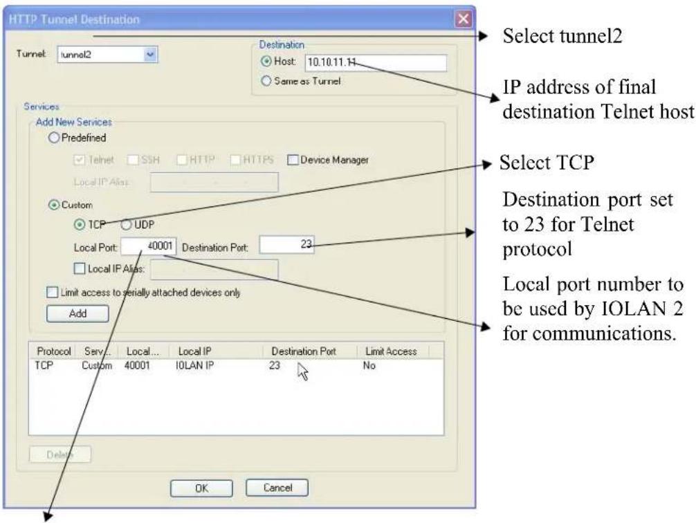
text_image
HTTP Tunnel Destination Tunnel: tunnel2 Destination Host: 10.10.11.14 Same as Tunnel Select tunnel2 IP address of final destination Telnet host Services Add New Services Predefined Telnet SSH HTTP HTTPS Device Manager Local IP Alias: Custom TCP UDP Local Port: 40001 Destination Port: 23 Local IP Alias: Limit access to serially attached devices only Add Protocol Serv... Local... Local IP Destination Port Limit Access TCP Custom 40001 IOLAN IP 23 No Delete OK Cancel Select TCP Destination port set to 23 for Telnet protocol Local port number to be used by IOLAN 2 for communications.Note: This value must match destination port number on IOLAN 1
The setup for HTTP Tunnel Relay is now complete.

natural_image
Abstract logo with a black letter 'A' inside a yellow circular frame with star-like patterns (no text or symbols)RADIUS and TACACS+
Introduction
This chapter describes the parameters that can be passed to the IOLAN when a user logs into the IOLAN (serial port set to profile Terminal) from external authentication RADIUS and TACACS+ servers.
RADIUS
Although RADIUS can be used strictly for external authentication, it can also be used to configure line and user parameters. Therefore, when a user is being authenticated using RADIUS, it is possible that the user's configuration is a compilation of the parameters passed back from RADIUS, the IOLAN parameters if the user has also been set up as a local user in the IOLAN, and the Default User's parameters for any parameters that have not been set by either RADIUS or the user's local configuration.
Supported RADIUS Parameters
This section describes the attributes which will be accepted by the IOLAN from a RADIUS server in response to an successful authentication request.
| Type Name Description | |||
| 1 | User-Name | Request | The name of the user to be authenticated. |
| 2 | User-Password | Request | The password of the user to be authenticated. |
| 4 | NAS-IP-Address | Response | The IOLAN’s IPV4 address. |
| 5 | NAS-Port | Response | If the user is connected to a physical port then the port number of the port is sent. If the user is connected to the IOLAN itself then a port number of 0 is sent. |
| Type | Name | Description | |
| 6 | Service-Type | Response | Indicates the service to use to connect the user to the IOLAN. A value of 6 indicates administrative access to the IOLAN. Supported values are:1—Login3—Callback-LoginEquivalent to the IOLAN User Service set by Type 15, Login-Service.2—Framed4—Callback-FramedEquivalent to the IOLAN User Service set by Type 7, Framed-Protocol.7—NAS prompt9—Callback NAS-promptEquivalent to IOLAN User Service DSLogin.6—Administrative User11—Callback Administrative UserEquivalent to IOLAN User Service DSLogin and the User gets Admin privileges. |
| 7 | Framed-Protocol | Response | The link layer protocol to be used by this user. Determines the User Service when Service-Type is set to Framed or Callback-Framed. Supported values are:1—PPP2—SLIP |
| 8 | Framed-IP-Address | Response | The IP Address to be assigned to this user for PPP or SLIP. |
| 9 | Framed-IP-Netmask | Response | The subnet to be assigned to this user for PPP or SLIP. |
| 12 | Framed-MTU | Response | Attribute indicates the Maximum Transmission Unit (MTU) to be configured for the user, when it is not negotiated by some other means such as PPP. |
| 13 | Framed-Compression | Response | Indicates a compression protocol to be used for the PPP or SLIP link. Supported value is:1—Van Jacobson TCP/IP compression. |
| 14 | Login-Host | Response | Indicates the host with which the user can connect to when the Service-Type is set to 1 (Login) or 3 (Callback-Login). |
| 15 | Login-Service | Response | Indicates the IOLAN User Service to use to connect the user a host. Supported values are:0—Telnet1—Rlogin2—TCP Clear5—SSH6—SSL Raw |
| 16 | Login-TCP-Port | Response | Indicates the TCP port with which the user is to be connected when the Service-Type is set to 1 (Login) or 3 (Callback-Login). |
| 19 | Callback-Number | Response | Specifies the callback phone number. This is the same implementation as 20 (Callback-ID), but takes precedence if 20 is set. |
| 20 | Callback-ID | Response | Specifies the callback phone number. This is the same implementation as 19 (Callback-Number), but 19 takes precedence if both are set. |
| 22 | Framed-Route | Response | When the PPP IPv4 interface comes up, the IOLAN will add routes to the user's PPP interface in the same order they were received |
| 25 | Class | Response | Received attributes are send in the Accounting Reply messages. |
| 26 | Vendor-Specific | Response | Perle's defined attributes for line access rights and user level. See Perle RADIUS Dictionary Example on page 303 for an example of this file.Line Access Rights for port n (where n is the line number):Name: Perle-Linc-Access-Port-nType: 100 + nData Type: IntegerValue: Disabled (0), ReadWrite(1), ReadInput(2), ReadInputWrite (3), ReadOutput (4), ReadOutputWrite (5), ReadOutputInput (6), ReadOutputInputWrite (7)Name: Perle-User-LevelType: 100Data Type: IntegerValue: Admin(1), Normal(2), Restricted(3), Menu(4)Name: Perle-Clustered-Port-AccessType: 99Data Type: IntegerValue: Disabled(0), Enabled(1) |
| 27 | Session-Timeout | Response | Maximum number of seconds the user will be allowed to stay logged on. |
| 28 | Idle-Timeout | Response | Use this timer to close a connection because of inactivity. When the Idle-Timeout expires, the IOLAN will end the connection. The maximum value is 4294967 seconds (about 49 days). A value of 0 (zero) means the Idle-Timeout will not expire, so the connection is permanently open. |
| 31 | Calling-Station-Id | Response | For reverse telnet and reverse ssh the IP address of the client will be sent. All other server type do not send this field. |
| 32 | NAS-Identifier | Response | If the identifier is configured then this field will be sent. |
| Type Name Description | |||
| 61 | NAS-Port-Type | Response | For reverse telnet and reverse ssh connections, a type of Virtual (5) will be sent. For a PPP connection type a type of Async (0) will be sent.For all direct connect service types a type of Async (0) will be sent. |
| 87 | NAS-Port-Id | Response | For sessions originating from the serial port:or “SERIAL:xx”, where xx starts at serial port 1.For reverse Telnet and SSH Ethernet sessions:“ETH:REVSESS:xx”, where xx is the serial port being accesses, otherwise 00 for a ILOAN management session.For Device manager sessions:“DEVMGR”For HTTP sessions:“HTTP” |
| 95 | NAS-IPv6-Address | Response | The IPv6 address of the IOLAN. |
| 96 | Framed-Interface-Id | Response | The remote IPv6 interface identifier for the remote end of the PPP link. |
| 98 | Login-IPv6-Host | Response8 | For LOGIN and CALLBACK service types, the IPv4 address of the login host is sent to the radius accounting host. |
| 99 | Framed-IPv6-Route | Response | When the PPP IPv6 interface comes up, the IOLAN will add routes to the user's PPP interface in the same order they were received. |
Accounting Message
This section describes the attributes which will be included by the IOLAN when sending an accounting message to the RADIUS server.
Type Name Description
| 1 User-Name The name of the user to be authenticated. | ||
| 4 NAS-IP-Address IP Address of IOLAN LAN interface. | ||
| 5 | NAS-Port | If the user is connected to a physical port then the port number of the port is sent. If the user is connected to the IOLAN itself then a port number of 0 is sent. |
| 6 | Service-Type | Indicates the service to use to connect the user to the IOLAN. A value of 6 indicates administrative access to the IOLAN. Supported values are:1—Login3—Callback-LoginEquivalent to the IOLANUser Serviceset by Type 15, Login-Service.2—Framed4—Callback-FramedEquivalent to the IOLANUser Serviceset by Type 7, Framed-Protocol.7—NAS prompt9—Callback NAS-promptEquivalent to IOLANUser Service DSPrompt.6—Administrative User11—Callback Administrative UserEquivalent to IOLANUser Service DSPromptand the User gets Admin privileges. |
| 14 Login-IP-Host For LOGIN and CALLBACK service types, the IPv4 address of the login host is sent to the radius accounting host. | ||
| 31 | Calling-Station-Id | For reverse telnet and reverse ssh the IP address of the client will be sent. All other server type do not send this field. |
| 32 | NAS-Identifier | If the identifier is configured then this field will be sent. |
| 40 | Acct-Status-Type | Indicates if this is the beginning or end of a session.Supported values are: 1 = Start 2 =Stop. |
| 42 | Acct-Input-Octets | Number of bytes which were received from the user during this session. |
| 43 | Acct-Output-Octets | Number of bytes where were transmitted to the user during this session. |
| 44 | Acct-Session-ID | A string which identifies the session. The same string must be used in the start and stop messages. |
| 45 | Acct-Authentic | Indicates how the user was authenticated. Supported values are: 1 = Local 2 = RADIUS. |
| Type | Name | Description |
| 46 | Acct-Session-Time | Number of seconds for which the user has been connected to a specific session. |
| 47 | Acct-Input-Packets | Number of packets which were received from the user during this session. |
| 48 | Acct-Output-Packets | Number of packets which were transmitted to the user during this session. |
| 49 | Acct-Terminate-Cause | Indicates how the session was terminated: Supported values include: 1 = User Request 2= Lost Carrier 3=Lost Service 4= Idle Timeout 5= Session Timeout 14 = Port Suspended 16 = Callback. |
| 61 | NAS-Port-Type | For reverse telnet and reverse ssh connections, a type of Virtual (5) will be sent. For a PPP connection type a type of Async (0) will be sent. For all direct connect service types a type of Async (0) will be sent. |
| 77 | Connect-Info | .For reverse telnet, reverse ssh and direct serial connections the serial port baud rate is send to the radius accounting server. |
| 87 NAS-Port-Id For sessions originating from the serial port:or “SERIAL:xx”, where xx starts at serial port 1.For reverse Telnet and SSH Ethernet sessions:“ETH:REVSESS:xx”, where xx is the serial port being accesses, otherwise 00 for a ILOAN management session.For Device manager sessions:“DEVMGR”For HTTP sessions:“HTTP” | ||
| 95 NAS-IPv6-Address The IPv6 address of the IOLAN | ||
| 98 | Login-IPv6-Host | For LOGIN and CALLBACK service types, the IPv4 address of the login host is sent to the radius accounting host. |
Mapped RADIUS Parameters to IOLAN Parameters
When authentication is being done by RADIUS, there are several Serial Port and User parameters that can be set by the RADIUS server. Any parameters sent by that RADIUS server that are not supported by the IOLAN are discarded. Below is a list of the RADIUS parameters and their IOLAN parameters:
RADIUS Parameter IOLAN Parameter
Service-Type This has no IOLAN field, although it needs
to be set to Framed-User in the RADIUS
server if the port is set for PPP or SLIP. For
a Console Management profile set the
RADIUS Service-Type to NAS prompt.
Framed-Protocol
Set to SLIP or PPP service.
Framed-Address Remote IP Address field under either SLIP or PPP.
Caution: the exception to the above rule is a Framed-Address value of 255.255.255.254. When this value is specified in the RADIUS file, the unit will use the Remote IP address configured for a PPP line in the IOLAN.
Framed-Netmask
IPv4 Subnet Mask field under either SLIP or PPP.
Framed-Compression
VJ Compression field under either SLIP or PPP.
Framed-MTU
MTU field under SLIP.
MRU field under PPP.
Idle-Timeout
Idle Timeout under the serial port Advanced settings.
Login-Service Corresponds to one
of the following User Service parameters: Telnet, Rlogin, TCP Clear, SSH, or SSL Raw.
Session-Timeout
Session Timeout under the serial port Advanced settings.
Callback-Number
Combination of the Enable Callback and Phone Number fields under User, Advanced settings.
Callback-ID
Combination of the Enable Callback and Phone Number fields under User, Advanced settings.
Perle RADIUS Dictionary Example
The IOLAN has defined Vendor Specific RADIUS attributes in order for the RADIUS server to be configured to support the IOLAN features of Line Access Rights and User Level. These attributes have been defined in Supported RADIUS Parameters on page 296 to allow the RADIUS server to be configured for RADIUS users to have this level of configuration.
See below for an example of the Perle defined attributes for the RADIUS server for a 4-port IOLAN (although the dictionary can contain 48 ports, even if they are not all defined):
<h1 id="perle-dictionary">Perle dictionary.</h1>
#
<h1 id="perle-systems-ltd">Perle Systems Ltd.</h1>
<h1 id="httpwwwperlecom">http://www.perle.com/</h1>
#
<h1 id="enable-by-putting-the-line-include-dictionaryperle-into">Enable by putting the line "$INCLUDE dictionary.perle" into</h1>
<h1 id="the-main-dictionary-file">the main dictionary file.</h1>
#
<h1 id="version-130-21-may-2008-add-attribute-for-clustered-port-access">Version: 1.30 21-May-2008 Add attribute for clustered port access</h1>
<h1 id="version-120-30-nov-2005-add-new-line-access-right-values-for-ports-up-to-49">Version: 1.20 30-Nov-2005 Add new line access right values for ports up to 49.</h1>
#
<h1 id="version-110-11-nov-2003-add-new-line-access-right-values">Version: 1.10 11-Nov-2003 Add new line access right values</h1>
<h1 id="version-100-17-jul-2003-original-release-for-vendor-specific-field-support">Version: 1.00 17-Jul-2003 original release for vendor specific field support</h1>
#
VENDOR Perle 1966
# Perle Extensions
ATTRIBUTE Perle-Clustered-Port-Access 99 integer Perle
ATTRIBUTE Perle-User-Level 100 integer Perle
ATTRIBUTE Perle-Line-Access-Port-1 101 integer Perle
ATTRIBUTE Perle-Line-Access-Port-2 102 integer Perle
ATTRIBUTE Perle-Line-Access-Port-3 103 integer Perle
ATTRIBUTE Perle-Line-Access-Port-4 104 integer Perle
ATTRIBUTE Perle-Line-Access-Port-5 105 integer Perle
ATTRIBUTE Perle-Line-Access-Port-6 106 integer Perle
ATTRIBUTE Perle-Line-Access-Port-7 107 integer Perle
ATTRIBUTE Perle-Line-Access-Port-8 108 integer Perle
ATTRIBUTE Perle-Line-Access-Port-9 109 integer Perle
ATTRIBUTE Perle-Line-Access-Port-10 110 integer Perle
ATTRIBUTE Perle-Line-Access-Port-11 111 integer Perle
ATTRIBUTE Perle-Line-Access-Port-12 112 integer Perle
ATTRIBUTE Perle-Line-Access-Port-13 113 integer Perle
ATTRIBUTE Perle-Line-Access-Port-14 114 integer Perle
ATTRIBUTE Perle-Line-Access-Port-15 115 integer Perle
ATTRIBUTE Perle-Line-Access-Port-16 116 integer Perle
ATTRIBUTE Perle-Line-Access-Port-17 117 integer Perle
ATTRIBUTE Perle-Line-Access-Port-18 118 integer Perle
ATTRIBUTE Perle-Line-Access-Port-19 119 integer Perle
ATTRIBUTE Perle-Line-Access-Port-20 120 integer Perle
ATTRIBUTE Perle-Line-Access-Port-21 121 integer Perle
ATTRIBUTE Perle-Line-Access-Port-22 122 integer Perle
ATTRIBUTE Perle-Line-Access-Port-23 123 integer Perle
ATTRIBUTE Perle-Line-Access-Port-24 124 integer Perle
ATTRIBUTE Perle-Line-Access-Port-25 125 integer Perle
ATTRIBUTE Perle-Line-Access-Port-26 126 integer Perle
ATTRIBUTE Perle-Line-Access-Port-27 127 integer Perle
ATTRIBUTE Perle-Line-Access-Port-28 128 integer Perle
ATTRIBUTE Perle-Line-Access-Port-29 129 integer Perle
| ATTRIBUTE | Perle-Line-Access-Port-30 | 130 integer | Perle |
| ATTRIBUTE | Perle-Line-Access-Port-31 | 131 integer | Perle |
| ATTRIBUTE | Perle-Line-Access-Port-32 | 132 integer | Perle |
| ATTRIBUTE | Perle-Line-Access-Port-33 | 133 integer | Perle |
| ATTRIBUTE | Perle-Line-Access-Port-34 | 134 integer | Perle |
| ATTRIBUTE | Perle-Line-Access-Port-35 | 135 integer | Perle |
| ATTRIBUTE | Perle-Line-Access-Port-36 | 136 integer | Perle |
| ATTRIBUTE | Perle-Line-Access-Port-37 | 137 integer | Perle |
| ATTRIBUTE | Perle-Line-Access-Port-38 | 138 integer | Perle |
| ATTRIBUTE | Perle-Line-Access-Port-39 | 139 integer | Perle |
| ATTRIBUTE | Perle-Line-Access-Port-40 | 140 integer | Perle |
| ATTRIBUTE | Perle-Line-Access-Port-41 | 141 integer | Perle |
| ATTRIBUTE | Perle-Line-Access-Port-42 | 142 integer | Perle |
| ATTRIBUTE | Perle-Line-Access-Port-43 | 143 integer | Perle |
| ATTRIBUTE | Perle-Line-Access-Port-44 | 144 integer | Perle |
| ATTRIBUTE | Perle-Line-Access-Port-45 | 145 integer | Perle |
| ATTRIBUTE | Perle-Line-Access-Port-46 | 146 integer | Perle |
| ATTRIBUTE | Perle-Line-Access-Port-47 | 147 integer | Perle |
| ATTRIBUTE | Perle-Line-Access-Port-48 | 148 integer | Perle |
| ATTRIBUTE | Perle-Line-Access-Port-49 | 149 integer | Perle |
Perle Clustered Port Access Values
| VALUE | Perle-Clustered-Port-Access | Disabled | 0 |
| VALUE | Perle-Clustered-Port-Access | Enabled | 1 |
Perle User Level Values
| VALUE | Perle-User-Level | Admin | 1 |
| VALUE | Perle-User-Level | Normal | 2 |
| VALUE | Perle-User-Level | Restricted | 3 |
| VALUE | Perle-User-Level | Menu | 4 |
Perle Line Access Right Values
| VALUE | Perle-Line-Access-Port-1 | Disabled | 0 |
| VALUE | Perle-Line-Access-Port-1 | Read-Write | 1 |
| VALUE | Perle-Line-Access-Port-1 | Read-Input | 2 |
| VALUE | Perle-Line-Access-Port-1 | Read-Input-Write | 3 |
| VALUE | Perle-Line-Access-Port-1 | Read-Output | 4 |
| VALUE | Perle-Line-Access-Port-1 | Read-Output-Write | 5 |
| VALUE | Perle-Line-Access-Port-1 | Read-Output-Input | 6 |
| VALUE | Perle-Line-Access-Port-1 | Read-Output-Input-Write | 7 |
| VALUE | Perle-Line-Access-Port-2 | Disabled | 0 |
| VALUE | Perle-Line-Access-Port-2 | Read-Write | 1 |
| VALUE | Perle-Line-Access-Port-2 | Read-Input | 2 |
| VALUE | Perle-Line-Access-Port-2 | Read-Input-Write | 3 |
| VALUE | Perle-Line-Access-Port-2 | Read-Output | 4 |
| VALUE | Perle-Line-Access-Port-2 | Read-Output-Write | 5 |
| VALUE | Perle-Line-Access-Port-2 | Read-Output-Input | 6 |
| VALUE | Perle-Line-Access-Port-2 | Read-Output-Input-Write | 7 |
| VALUE | Perle-Line-Access-Port-3 | Disabled | 0 |
| VALUE | Perle-Line-Access-Port-3 | Read-Write | 1 |
| VALUE | Perle-Line-Access-Port-3 | Read-Input | 2 |
| VALUE | Perle-Line-Access-Port-3 | Read-Input-Write | 3 |
| VALUE | Perle-Line-Access-Port-3 | Read-Output | 4 |
| VALUE | Perle-Line-Access-Port-3 | Read-Output-Write | 5 |
| VALUE | Perle-Line-Access-Port-3 | Read-Output-Input | 6 |
| VALUE | Perle-Line-Access-Port-3 | Read-Output-Input-Write | 7 |
| VALUE | Perle-Line-Access-Port-4 | Disabled | 0 |
| VALUE | Perle-Line-Access-Port-4 | Read-Write | 1 |
| VALUE | Perle-Line-Access-Port-4 | Read-Input | 2 |
| VALUE | Perle-Line-Access-Port-4 | Read-Input-Write | 3 |
| VALUE | Perle-Line-Access-Port-4 | Read-Output | 4 |
| VALUE | Perle-Line-Access-Port-4 | Read-Output-Write | 5 |
| VALUE | Perle-Line-Access-Port-4 | Read-Output-Input | 6 |
| VALUE | Perle-Line-Access-Port-4 | Read-Output-Input-Write | 7 |
...
TACACS+
Although TACACS+ can be used strictly for external authentication, it can also be used to configure Serial Port and User parameters. Therefore, when a user is being authenticated using TACACS+, it is possible that the user's configuration is a compilation of the parameters passed back from the TACACS+ authentication server, the User's IOLAN parameters if the user has also been set up as a local user in the IOLAN, and the Default User's parameters for any parameters that have not been set by either TACACS+ or the User's local configuration.
User and Serial Port parameters can be passed to the IOLAN after authentication for users accessing the IOLAN from the serial side and users accessing the IOLAN from the Ethernet side connections.
Accessing the IOLAN Through a Serial Port Users
This section describes the attributes which will be accepted by the IOLAN from a TACACS+ server in response to an authentication request for Direct Users.
| Name Value(s) Description | ||
| priv-lvl 12-15 (Admin) | The IOLAN privilege level. | |
| 8-11 (Normal) | ||
| 4-7 (Restricted) | ||
| 0-3 (Menu) | ||
| Perle_User_Service 0 (Telnet) | Corresponds to the User Service setting in the IOLAN. | |
| 1 (Rlogin) | ||
| 2 (TCP_Clear) | If no value is specified, DSPrompt is the default User Service. | |
| 3 (SLIP) | ||
| 4 (PPP) | ||
| 5 (SSH) | ||
| 6 (SSL_Raw) | ||
| service = telnet | Settings when Perle_User_Service is set to 0. | |
| { | ||
| addr = | IPv4 or IPv6 address | |
| port = | TCP port number | |
| } | ||
| service = rlogin | Settings when Perle_User_Service is set to 1. | |
| { | ||
| addr = | IPv4 or IPv6 address | |
| } | ||
Name Value(s) Description
service = tcp_clear
{
    addr = IPv4 or IPv6 address
    port = TCP port number
}

service = slip
{
    routing = true (Send and Listen)
    false (None)
    addr = IPv4 or IPv6 address
}

service = ppp
{
    routing = true (Send and Listen)
    false (None)
    addr = IPv4 or IPv6 address
    port = TCP port number
    ppp-vj-slot-compression
    callback-dialstring
    } true or false
    phone number, no punctuation

service = ssh
{
    addr = IPv4 or IPv6 address
    port = TCP port number
}

service = ssl_raw
{
    addr = IPv4 or IPv6 address
    port = TCP port number
}
Accessing the IOLAN Through a Serial Port User Example Settings
The following example shows the parameters that can be set for users who are accessing the IOLAN from the serial side. These settings should be included in the TACACS+ user configuration file.
Service = EXEC
{
    priv-lvl = x    # x = 12-15 (Admin)
    # x = 8-11 (Normal)
    # x = 4-7 (Restricted)
    # x = 0-3 (Menu)

    timeout=x    # x = session timeout in seconds

    idletime=x    # x = Idle timeout in seconds

    Perle_User_Service = x    # x = 0 Telnet
    # x = 1 Rlogin
    # x = 2 TCP_Clear
    # x = 3 SLIP
    # x = 4 PPP
    # x = 5 SSH
    # x = 6 SSL_RAW
    # If not specified, command prompt
}

<h1 id="depending-on-what-perle_user_service-is-set-to">Depending on what Perle_User_Service is set to</h1>

service = telnet
{
    addr = x.x.x.x    # ipv4 or ipv6 addr
    port = x    # tcp_port #
}

service = rlogin
{
    addr = x.x.x.x    # ipv4 or ipv6 addr
}

service = tcp_clear
{
    addr = x.x.x.x    # ipv4 or ipv6 addr
    port = x    # tcp_port #
}

service = slip
{
    routing=x    # x = true (Send and Listen)
    # x = false (None)
    addr = x.x.x.x    # ipv4 addr
}
service = ppp
{
    routing=x    # x = true (Send and Listen)
    # x = false (None)
    addr = x.x.x.x    # ipv4 or ipv6 addr
    ppp-vj-slot-compression = x  # x = true or false
    callback-dialstring = x  # x = number to callback on
}

service = ssh
{
    addr = x.x.x.x    # ipv4 or ipv6 addr
    port = x    # tcp_port #
}

service = ssl_raw
{
    addr = x.x.x.x    # ipv4 or ipv6 addr
    port = x    # tcp_port #
}
Accessing the IOLAN from the Network Users
This section describes the attributes which will be accepted by the IOLAN from a TACACS+ server in response to an authentication request for Reverse Users. The TACACS+ service needs to be set to EXEC/raccess or just raccess on the well known port.
| Name Value(s) Description | |
| priv-lvl 12-15 (Admin) | The IOLAN privilege level. |
| 8-11 (Normal) | |
| 4-7 (Restricted) | |
| 0-3 (Menu) | |
| Perle_Line_Access_# # = port number | For the specified line, provides the User's Line Access rights. |
| 0 (Disabled) | |
| 1 (ReadWrite) | |
| 2 (ReadInput) | |
| 3 (ReadInputWrite) | |
| 4 (ReadOuptut) | |
| 5 (ReadOutputWrite) | |
| 6 (ReadOutputInput) | |
| 7 (ReadOuputWrite) | |
| timeout 0-4294967 Session timeout in seconds. | |
| idletime 0-4294967 Idle timeout in seconds. | |
| Perle_Clustered_Port_Access 0 (Disabled) | Control access to clustered ports. |
| 1 (Enabled) | |
Accessing the IOLAN from the Network User Example Settings
The following example shows the parameters that can be set for users who are accessing the IOLAN from the Ethernet side. These settings should be included in the TACACS+ user configuration file.
<h1 id="settings-for-telnetssh-access">Settings for telnet/SSH access</h1>
service = raccess
{
    priv-lvl = x    # x = 12-15 (Admin)
    # x = 8-11 (Normal)
    # x = 4-7 (Restricted)
    # x = 0-3 (Menu)

    Perle_Line_Access_i=x    # i = port number
    # x = 0 (Disabled)
    # x = 1 (Read/Write)
    # x = 2 (Read Input)
    # x = 3 (Read Input/Write)
    # x = 4 (Read Output)
    # x = 5 (Read Output/Write)
    # x = 6 (Read Output/Input)
    # x = 7 (Read Output/Write)

    timeout=x    # x = session timeout in seconds

    idletime=x    # x = Idle timeout in seconds

    Perle_Clustered_Port_Access=x    # x = 0 (Disabled)
    # x = 1 (Enabled)
}
Users who are accessing the IOLAN through WebManager or DeviceManager and are being authenticated by TACACS+ must have the Admin privilege level and the TACACS+ service level must be set to EXEC.
<h1 id="settings-for-webmanager-and-devicemanager-access">Settings for WebManager and DeviceManager access</h1>
service=EXEC
{
priv-lvl = 12    # x = 12-15 (Admin)

Perle_Line_Access_i=x    # i = port number
    # x = 0 (Disabled)
    # x = 1 (Read/Write)
    # x = 2 (Read Input)
    # x = 3 (Read Input/Write)
    # x = 4 (Read Output)
    # x = 5 (Read Output/Write)
    # x = 6 (Read Output/Input)
    # x = 7 (Read Output/Write)

Perle_Clustered_Port_Access = 1 # enable clustered port access
}

natural_image
Abstract logo design featuring a black letter 'B' inside a yellow circular frame with star-like patterns (no text or symbols)SSL/TLS Ciphers
Introduction
This appendix contains a table that shows valid SSL/TLS cipher combinations.
Some combinations of cipher groups are not available on FIPS firmware versions.
Valid SSL/TLS Ciphers
This chart displays all of the valid SSL/TLS combinations.
| Full Name | Key-Exchange | Authentication | Encryption | Key-Size | HMAC |
| EDCHE-ECDSA-AES256-GCM-SHA384 | Kx=ECDH | Au=ECDSA | Enc=AES-GCM | 256 | Mac=SHA384 |
| ECDHE-ECDSA-AES256-SHA384 | Kx=ECDH | Au=ECDSA | Enc=AES | 256 | Mac=SHA384 |
| ECDHE-ECDSA-AES256-SHA | Kx=ECDH | Au=ECDSA | Enc=AES | 256 | Mac=SHA1 |
| DHE-DSS-AES256-GCM-SHA384 | Kx=DH | Au=DSS | Enc=AES-GCM | 256 | Mac=SHA384 |
| DHE-RSA-AES256-GCM-SHA384 | Kx=DH | RSA | Enc=AES-GCM | 256 | Mac=SHA384 |
| DHE-RSA-AES256-SHA256 | Kx=DH | RSA | Enc=AES | 256 | Mac=SHA256 |
| AES256-GCM-SHA384 | Kx=RSA | RSA | Enc=AES-GCM | 256 | Mac=SHA384 |
| AES256-SHA256 | Kx=RSA | RSA | Enc=AES | 256 | Mac=SHA256 |
| DHE-DSS-AES256-SHA256 | Kx=DH | DSS | Enc=AES | 256 | Mac=SHA256 |
| DHE-RSA-AES256-SHA | Kx=DH | RSA | Enc=AES | 256 | Mac=SHA1 |
| DHE-DSS-AES256-SHA | Kx=DH | DSS | Enc=AES | 256 | Mac=SHA1 |
| ADH-AES256-GCM-SHA384 | Kx=DH | None | Enc=AES-GCM | 256 | Mac=SHA384 |
| ADH-AES256-SHA256 | Kx=DH | None | Enc=AES | 256 | Mac=SHA256 |
| ADH-AES256-SHA | Kx=DH | None | Enc=AES | 256 | SHA1 |
| AES256-SHA | Kx=RSA | Au=RSA | Enc=AES | 256 | Mac=SHA1 |
| ECDHE-RSA-AES128-GCM-SH256 | Kx=ECDH | Au-RSA | Enc=AES-GCM | 128 | Mac=SHA256 |
| ECDHE-ECDSA-AES128-GCM-SHA256 | Kx=ECDH | Au=ECDSA | Enc=AES-GCM | 128 | SHA256 |
| ECDHE-ECDSA-AES128-SHA256 | Kx=ECDH Au=ECDSA Enc=AES 128 SHA256 | ||||
| ECDHE-ECDSA-AES128-SHA | Kx=ECDH | Au=ECDSA | Enc=AES | 128 | SHA1 |
| DHE-DSS-AES128-GCM-SH256 | Kx=DH | Au=DSS | Enc=AES-GCM | 128 | SHA256 |
| DHE-RSA-AES128-GCM-SHA256 | Kx=DH Au=RSA Enc=AES-GCM 128 SHA256 | ||||
| DHE-RSA-AES128-SHA256 | Kx=DH | Au=RSA | Enc=AES | 128 | SHA256 |
| DHE-DSS-AES128-SHA256 | Kx=DH | Au=DSS | Enc=AES | 128 | SHA256 |
| DHE-RSA-AES128-SHA | Kx=DH | Au=RSA | Enc=AES | 128 | SHA1 |
| DHE-DSS-AES128-SHA | Kx=DH | Au=DSS | Enc=AES | 128 | SHA1 |
| ADH-AES128-SHA256 | Kx=DH | Au=None | Enc=AES | 128 | SHA256 |
| ADH-AES128-SHA | Kx=DH | Au=None | Enc=AES | 128 | SHA1 |
| AES128-GCM-SHA256 | Kx=RSA | Au=RSA | Enc=AES-GCM | 128 | SHA256 |
| AES128-SHA256 | Kx=RSA | Au=RSA | Enc=AES | 128 | SHA256 |
| AES128-SHA | Kx=RSA | Au=RSA | Enc=AES | 128 | SHA1 |
| RC2-CBC-MD5 | Kx=RSA | Au=RSA | Enc=RC2 | 128 | MD5 |
| ADH-RC4-MD5 | Kx=DH | Au=None | Enc=RC4 | 128 | MD5 |
| RC4-SHA | Kx=RSA | AU=RSA | Enc=RC4 | 128 | SHA1 |
| RC54-MD5 | Kx=RSA | Au=RSA | Enc=RC4 | 128 | MD5 |
| ECDHE-ECDSA-DES-CBC3-SHA | Kx=ECDH | Au=ECDSA | Enc=3DES | 168 | SHA1 |
| EDH-RSA-DES-CBC3-SHA | Kx=DH | Au=RSA | Enc=3DES | 168 | SHA1 |
| EDH-DSS-DES-CBC3-SHA | Kx=DH | Au=DSS | Enc=3DES | 168 | SHA1 |
| ADH-DES-CBC3-SHA | Kx=DH | Au=None | Enc=3DES | 168 | SHA1 |
| DES-CBC3-SHA | Kx=RSA | Au=RSA | Enc=3DES | 168 | SHA1 |
| DES-CBC3-MD5 | Kx=RSA | Au=RSA | Enc=3DES | 168 | MD5 |
| EDH-RSA-DES-CBC-SHA | Kx=DH | Au=RSA | Enc=DES | 56 | SHA1 |
| EDH-DSS-DES-CBC-SHA | Kx=DH | Au=DSS | Enc=DES | 56 | SHA1 |
| ADH-DES-CBC-SHA | Kx=DH | Au=None | Enc=DES | 56 | SHA1 |
| DES-CBC-SHA | Kx=RSA | Au=RSA | Enc=DES | 56 | SHA1 |
| EXP-EDH-RSA-DES-CBC-SHA | Kx=DH-512 | Au=RSA | Enc=DES | 40 | SHA1 |
| EXP-EDH-DSS-DES-CBC-SHA | Kx=DH-512 | Au=DSS | Enc=DES | 40 | SHA1 |
| EXP-DES-CBC-SHA | Kx=RSA-512 | Au=RSA | Enc=DES | 40 | SHA1 |
| EXP-RC2-CBC-MD5 | Kx=RSA-512 | Au=RSA | Enc=RC2 | 40 | MD5 |
| EXP-ADH-DES-CBC-SHA | Kx=DH-512 | Au-none | Enc=DES | 40 | SHA1 |
| EXP-ADH-RC4-MD5 | Kx=DH-512 | Au=none | Enc=RC4 | 40 | MD5 |
| EXP-RC4-MD5 | Kx=RSA-512 | Au=RSA | Enc=RC4 | 40 | MD5 |
Virtual Modem Initialization Commands
Virtual Modem initialization commands are only supported on IOLAN firmware and configurators version 3.2 or higher.
You can initialize the modem connection using any of the following commands:
| Command | Description Options | |
| ATQn Quiet mode. Determines if result codes will be sent to the connected terminal. Basic results codes are OK, CONNECT, RING, NO CARRIER, and ERROR.Setting quiet mode also suppresses the “RING” message for incoming calls. | n=0, result codes will be sent.(default)n=1, no result codes will be sent. | |
| ATVn Verbose mode. Determines if result codes are displayed as text or numeric values. | n=0, display as numeric values.n=1, display as text. (default) | |
| ATEn Echo mode. Determines whether characters sent from the serial device will be echoed back by the IOLAN when VModem is in “command” mode. Any AT commands not supported will return an “ok” if n=1. | n=0, disable echo.n=1, enable echo. (default) | |
| +++ATH Hang up. This command instructs the IOLAN to terminate the current session and go into “command” mode. | ||
| ATA Answer call. Instructs the VModem to accept connection requests. VModem will give the terminal up to 3 minutes to answer the call. If the ATA is not received within 3 minutes, all pending sync messages will be discarded. | ||
| ATI0 Return the modem manufacturer name. | ||
| ATI3 Return the modem model name. | ||
| ATS0 Sets the value of the S0 register. The S0 register controls the “auto answer” behavior.In “manual” mode, the IOLAN will not accept incoming sessions until an ATA is issued by the serial device. In “auto answer” mode, the IOLAN will automatically accept an incoming connection request. | Register=0, sets “manual answer” modeRegister=1-255, “auto answer” mode (default) | |
| Command | Description | Options |
| AT&Z1 Set com | command allows the user to store an IP address and port number or phone number to use when making a connection. The user will issue an ATDS1 to cause the IOLAN to initiate the connection. | |
| AT&Sn Sets the | behavior of IOLAN's DTR signal. (DSR from a DCE perspective) | n=0, DTR signal always high. (default)n=2, DTR signal acts as DCD.n=3, DTR signal acts as RI. |
| AT&Rn Sets the | behavior of IOLAN's RTS signal. (CTS from a DCE perspective)If line is configured for hardware flow control, the RTS is used for this purpose and the setting of this command is ignored. | n=0, RTS always high. (default).n=3, RTS signal acts as DCD.n=4, RTS signal acts as RI. |
| AT&Cn | Sets the behaviour of the DCD signal. | n=0, DCD always on.n=1, DCD follows state of connection (off when no connection, on when TCP connection exists). (dcftault) |
| AT&F Sets the | modes back to the factory defaults. This is a hard-coded default configuration which does not look at any user configuration. | |
| ATS2 Sets the | value of the S2 register. The S2 register controls which character is used to enter "command" mode. (this is the potential replacement for the +++ (default) in front of the ATH command).This register will hold the hexadecimal value of the "escape" character. Any value > 27 will disable the ability to escape into "command" mode. | |
| ATS12 Sets the | value of the S12 register. The S12 register controls the minimum length of idle time which must elapse between the receipt of the escape character and the A (first character of the ATH sequence). Units are 1/50th of a second. The default is 50 = 1 second. | |
| ATO (ATD with no phone number) Establishes a connection using the IP and port specified in the telephone number field. | ||
| ATDS1 Establishes a connection using the IP and port (or phone number) specified in the Phone Number field (stored by the AT&Z1 command). | ||

natural_image
Abstract logo design featuring a black letter 'D' inside a yellow circular frame with star-like elements (no text or symbols)Pinouts and Cabling Diagrams
Serial Pinouts
DB25 Male
This section defines the pinouts for the DB25 male connection used on the 1-port IOLAN. The power out pin (Pin 9) is available in the SDS model only.
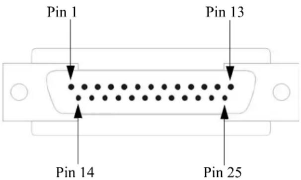
text_image
Pin 1 Pin 13 Pin 14 Pin 25The following table provides pinout information:
| Pinout | EIA-232 | EIA-422 | EIA-485Full Duplex | EIA-485Half Duplex |
| 1 | Shield | Shield | Shield | Shield |
| 2 (out) TxD | ||||
| 3 (in) RxD | ||||
| 4 (out) RTS | ||||
| 5 (in) CTS | ||||
| 6 (in) DSR | ||||
| 7 GND GND GND GND | ||||
| 8 (in) DCD | ||||
| 9 | Power out | Power out | Power out | Power out |
| 12 | Power in | Power in | Power in | Power in |
| 13 | CTS- | |||
| 14 | TxD+ | TxD+ | DATA+ | |
| 1518 RTS+ | TxD- | TxD- | DATA- | |
| 19 RTS- | ||||
| 20 (out) DTR | ||||
| 21 RxD+ RxD+ | ||||
| 22 RxD- RxD- | ||||
| 25 CTS+ | ||||
The power in pin (pin 12) can be 9-30VDC.
DB25 Female
This section defines the pinouts for the DB25 female connection used on the 1-port IOLAN. The power out pin (Pin 9) is available in the SDS model only.
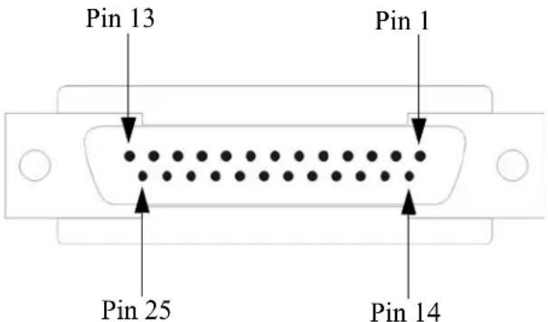
text_image
Pin 13 Pin 1 Pin 25 Pin 14The following table provides pinout information:
| Pinout | EIA-232 | EIA-422 | EIA-485Full Duplex | EIA-485Half Duplex |
| 1 | Shield | Shield | Shield | Shield |
| 2 (in) RxD | ||||
| 3 (out) TxD | ||||
| 4 (in) CTS | ||||
| 5 (out) RTS | ||||
| 6 (out) DTR | ||||
| 7 | GND | GND | GND | GND |
| 8 (in) DCD | ||||
| 9 | Power out | Power out | Power out | Power out |
| 12 | Power in | Power in | Power in | Power in |
| 13 RTS- | ||||
| 14 RxD+ RxD+ | ||||
| 15 RxD- | RxD- | |||
| 18 CTS+ | ||||
| 19 CTS- | ||||
| 20 (in) DSR | ||||
| 21 TxD+ | TxD+ DATA+ | |||
| 22 TxD- | TxD- DATA- | |||
| 25 RTS+ | ||||
The power in pin (pin 12) can be 9-30VDC.
RJ45
The RJ45 serial connector is available on IOLAN rack mount, desktop, Sun/Cisco, and medical unit models. The RJ45 pinouts vary depending on the IOLAN model. See the appropriate section for the RJ45 pinout information specific to your IOLAN model.
| IOLAN model | Number of Pins See... |
| desktop (1-port, 2-port, 4-port and 8-port) | 10 RJ45 (for desktop and rack mount models) |
| rack mount 8 RJ45 (for desktop and rack mount models) | |
| SCS48C/SCS32C/SCS16C/SCS8C (Sun/Cisco) | 8 RJ45 (for SCS48C/SCS32C/SCS16C/SCS8C models) |
| SDS8C/SDS16C/SDS32C (Dual Ethernet and Electric Utility models) | 8 RJ45 (for SDS32C/SDS16C/SDS8C) |
| medical unit models 10 RJ45 (for medical unit models) | |
RJ45 (for desktop and rack mount models)
This section defines the pinouts for the RJ45 connection. 1-port, 2-port, and 4-port desktop IOLAN models have a 10-pin RJ45 connector, however they can support an 8-pin connector if there is no requirement for power in (pin 1) or power out (pin 10). The STS8-D and all rack mount IOLAN models have an 8-pin RJ45 connector.
Pin 1 Pin 10
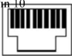
The following table provides pinout information:
| Pinout10-pin | Pinout8-pin | EIA-232 | EIA-422 | EIA-485Full Duplex | EIA-485Half Duplex |
| 1 | Power In | Power In | Power In | Power In | |
| 2 (in) 1 DCD | |||||
| 3 (out) | 2 | RTS | TxD+ | TxD+ | DATA+ |
| 4 (in) 3 DSR | |||||
| 5 (out) | 4 | TxD | TxD- | TxD- | DATA- |
| 6 (in) | 5 | RxD | RxD+ | RxD+ | |
| 7 | 6 | GND | GND | GND | GND |
| 8 (in) | 7 | CTS | RxD- | RxD- | |
| 9 (out) 8 DTR | |||||
| 10 | Power out | Power out | Power out | Power out | |
The power in pin (Pin 1) can be 9-30VDC. The 2-port IOLAN has power in on Port 2 only. The 4-port IOLAN has power in on Port 4 only.
RJ45 (for SCS48C/SCS32C/SCS16C/SCS8C models)
This section defines the pinouts for the RJ45 connection for the SCS48C/SCS32C/SCS16C/SCS8C (Sun/Cisco) models only.
Pin 1
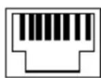
Pin 8
The following table provides pinout information, including the different pinouts for the Admin port and serial ports:
| Pinout8-pin | EIA-232Admin Port | EIA-232Serial Ports |
| 1 DCD (in) RTS (out) | ||
| 2 RTS (out) DTR (out) | ||
| 3 DSR (in) TxD (out) | ||
| 4 TxD (out) GND | ||
| 5 RxD (in) GND | ||
| 6 GND RxD (in) | ||
| 7 CTS (in) DSR/DCD (in) | ||
| 8 DTR (out) CTS (in) | ||
RJ45 (for SDS32C/SDS16C/SDS8C)
Dual Ethernet and Electric Utility models
This section defines the pinouts for the RJ45 connection for the Dual Ethernet (SDSxxC models) and Electric Utility models. The serial ports can be set to operate in EIA-232, EIA-422 or EIA-485 mode. The table provides the pinout for each of the modes of operation. The console port is an EIA-232 dedicated port. It's pinout is detailed in a separate table below.
Pin 1
Pin 8
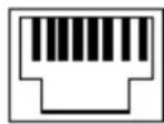
The following table provides pinout information for the serial ports:
| Pin# | EIA-232 | EIA-422 | EIA-485 Full Duplex | EIA-485 Half Duplex |
| 1 | RTS (out) | TxD+ | TxD+ | DATA+ |
| 2 | DTR(out) | |||
| 3 | TxD (out) | TxD- | TxD- | DATA- |
| 4 | GND GND GND GND | |||
| 5 | GND GND GND GND | |||
| 6 | RxD (in) RxD+ RxD+ | |||
| 7 | DSR (in) | |||
| 8 | CTS (in) | RxD- | RxD- |
The following table provides pinout information for the Admin port. For some models Perle supply's a RJ45 Admin cable (part# 1107015-10) that should be used to connect from the Admin port on the IOLAN to the (some models) Perle supplied RJ45 to serial adapter.
| Pinout 8-pin | EIA-232 Admin Port |
| 1 DCD (in) | |
| 2 RTS (out) | |
| 3 DSR (in) | |
| 4 TxD (out) | |
| 5 RxD (in) | |
| 6 GND | |
| 7 CTS (in) | |
| 8 DTR (out) | |
RJ45 (for medical unit models)
This section defines the pinouts for the RJ45 connection for the medical unit models.
Pin 1
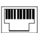
Pin 10
The following table provides pinout information:
Pinout
10-pin EIA-232
| 1 DTR (out) |
| 2 TxD (out) |
| 3 RxD (in) |
| 4 DCD (in) |
| 5 RTS (out) |
| 6 CTS (in) |
| 7 low current output (-12V) (out) |
| 8 low current output (+12V) (out) |
| 9 GND |
| 10 Shield |
DB9 Male (Serial Only)
This section defines the pinouts for the DB9 male connection used on the 1-port IOLAN that is serial only (not I/O).
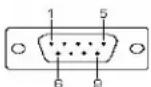
The following table provides pinout information:
| Pinout9-pin | EIA-232 | EIA-422/485Full Duplex | EIA-485Half Duplex |
| 1 (in) DCD | |||
| 2 (in) RxD RxD+ | |||
| 3 (out) TxD TxD+ TxD+/RxD+ | |||
| 4 (out) DTR | |||
| 5 GND GND GND | |||
| 6 (in) DSR RxD- | |||
| 7 RTS | |||
| 8 (in) CTS | |||
| 9 TxD- TxD-/RxD- | |||
DB9 Male I/O
This section defines the pinouts for the DB9 male connection used on the 1-port IOLAN I/O models.
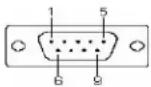
The following table provides pinout information:
| Pinout9-pin | EIA-232 | EIA-422/485Full Duplex | EIA-485Half Duplex |
| 1(in) DCD | |||
| 2 (in) RxD RxD+ | |||
| 3 (out) TxD TxD- TxD-/RxD- | |||
| 4 (out) DTR | |||
| 5 GND GND GND | |||
| 6 (in) DSR RxD- | |||
| 7 RTS TxD+ TxD+/RxD+ | |||
| 8 (in) CTS | |||
| 9 | |||
Power Over Ethernet Pinouts
This section defines the pinouts for the RJ45 Ethernet connection used on the IOLAN SDS P or IOLAN SCS P models.
Pin 1 Pin 8
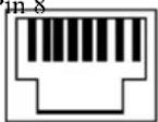
The following table provides pinout information:
| Pinout | Standard | 802.3AF Unit-4 Wire | 802.3AF Unit-8 Wire |
| 1 | Tx+ | Tx+/+Voltage | Tx+ |
| 2 | Tx- | Tx-/+Voltage | Tx- |
| 3 | Rx+ | Rx+/-Voltage | Rx+ |
| 4 | N/C | +Voltage | |
| 5 | N/C | +Voltage | |
| 6 | Rx- | Rx-/-Voltage | Rx- |
| 7 | N/C | -Voltage | |
| 8 | N/C | -Voltage |
EIA-232 Cabling Diagrams
This section shows how to create EIA-232 cables that are compatible with the Device Server.
Terminal DB25 Connector
The following diagrams show how the null modem cable should be configured when connecting to a terminal DB25.
DB25 Male
| IOLAN DS1DB25 (DTE) | Terminal DB25(DTE) |
| 2 (TxD) 3 (RxD) | |
| 3 (RxD) 2 (TxD) | |
| 4 (RTS) 5 (CTS) | |
| 5 (CTS) 4 (RTS) | |
| 6 (DSR) 20 (DTR) | |
| 7 (GND) 7 (GND) | |
| 20 (DTR) 6 (DSR) |
DB25 Female
| IOLAN DS1DB25 (DCE) | Terminal DB25(DTE) |
| 3 (TxD) 3 (RxD) | |
| 2 (RxD) 2 (TxD) | |
| 5 (RTS) 5 (CTS) | |
| 4 (CTS) 4 (RTS) | |
| 20 (DSR) 20 (DTR) | |
| 7 (GND) 7 (GND) | |
| 6 (DTR) 6 (DSR) |
RJ45
This cabling table does NOT apply to SCS48C/SCS32C/SCS16C/SCS8C (Sun/Cisco), SDS32C/SDS16C/SDS8C (Electrical Utility) or medical unit models.
| IOLAN RJ45 | Terminal DB25(DTE) |
| 10-pin 8-pin | |
| 4 (DSR) 3 20 (DTR) | |
| 3 (RTS) 2 5 (CTS) | |
| 5 (TxD) 4 3 (RxD) | |
| 6 (RxD) 5 2 (TxD) | |
| 7 (GND) 6 7 (GND) | |
| 8 (CTS) 7 4 (RTS) | |
| 9 (DTR) 8 6 (DSR) |
Cabling for SCS48C/SCS32C/SCS16C/SCS8C (Sun/Cisco) and SDS32C/SDS16C/SDS8C (Electrical Utility).
| IOLAN RJ45 | Terminal DB25 (DTE) |
7 (DSR) 20(DTR)
1 (RTS) 5 (CTS)
3 (TxD) 3 (RxD)
6 (RxD) 2 (TxD)
4 (GND) 7 (GND)
8 (CTS) 4 (RTS)
2 (DTR) 6 (DSR)
DB9 Male
| IOLAN DS1DB9 Male | Terminal DB25(DTE) |
| 3 (TxD) 3 (RxD) | |
| 2 (RxD) 2 (TxD) | |
| 7 (RTS) 5 (CTS) | |
| 8 (CTS) 4 (RTS) | |
| 6 (DSR) 20 (DTR) | |
| 5 (GND) 7 (GND) | |
| 4 (DTR) 6 (DSR) |
Modem DB25 Connector
The following diagrams show how a standard straight through cable should be configured when connecting to a DB25 modem.
DB25 Male
| IOLAN DS1DB25 (DTE) | Modem DB25(DCE) |
| 2 (TxD) 2 (RxD) | |
| 3 (RxD) 3 (TxD) | |
| 4 (RTS) 4 (CTS) | |
| 5 (CTS) 5 (RTS) | |
| 6 (DSR) 6 (DSR) | |
| 7 (GND) 7 (GND) | |
| 8 (DCD) 8 (DCD) | |
| 20 (DTR) 20 (DTR) |
RJ45
This cabling table does NOT apply to SCS48C/SCS32C/SCS16C/SCS8C (Sun/Cisco), SDS32C/SDS16C/SDS8C (Electrical Utility) or medical unit models.
| IOLAN RJ45 | Modem DB25(DCE) |
| 10-pin 8-pin | |
| 2 (DCD) 1 8 (DCD) | |
| 3 (RTS) 2 4 (CTS) | |
| 4 (DSR) 3 6 (DSR) | |
| 5 (TxD) 4 2 (RxD) | |
| 6 (RxD) 5 3 (TxD) | |
| 7 (GND) 6 7 (GND) | |
| 8 (CTS) 7 5 (RTS) | |
| 9 (DTR) 8 20 (DTR) |
DB9 Male
| IOLAN DS1DB9 Male | Modem DB25(DCE) |
| 1 (DCD) 8 (DCD) | |
| 2 (RxD) 3 (TxD) | |
| 3 (TxD) 2 (RxD) | |
| 4 (DTR) 20 (DTR) | |
| 5 (GND) 7 (GND) | |
| 6 (DSR) 6 (DSR) | |
| 7 (RTS) 4 (CTS) | |
| 8 (CTS) 5 (RTS) |

natural_image
Abstract logo design featuring a stylized letter 'E' within a yellow circular frame with star-like elements (no text or symbols)Configuring Serial Ports
Introduction
The Serial section is used to configure the serial ports on your IOLAN. The following configuration windows are available:
- Serial Ports—Configures the type of connection that the serial port is being used for. This is accomplished by selecting a connection profile and then configuring the applicable parameters for that profile. See Serial Ports for more information.
- Port Buffering—Configures serial port data buffering preferences. See Port Buffering for more information.
- Advanced—Configures those parameters that are applicable to specific environments. You will find modem and TruePort configuration options, in addition to others, here. See Advanced for more information.
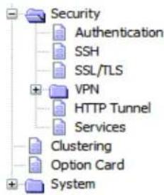
text_image
Security Authentication SSH SSL/TLS VPN HTTP Tunnel Services Clustering Option Card SystemSerial Ports
Overview
Each IOLAN serial port can be connected to serial device. Each serial port can then be configured according to a serial port profile that coincides with the serial device attached to that serial port and how the serial device is accessed/used.
Functionality
When you select the Serial Ports navigation option, you will see a list with the number of serial ports on your IOLAN. As you configure the serial ports, the information for each serial port is displayed.
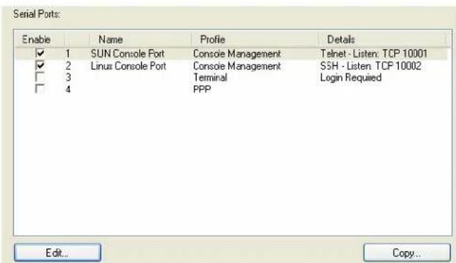
text_image
Serial Ports: Enable Name Profile Details ✓ 1 SUN Console Port Console Management Telnet - Listen: TCP 10001 ✓ 2 Linux Console Port Console Management SSH - Listen TCP 10002 □ 3 Terminal Login Required □ 4 PPP Edit... Copy...To configure/change a serial port, click the Edit button.
Editing a Serial Port
In the Serial Port Settings window, click on a serial port and then click the Edit button, the following window is displayed:
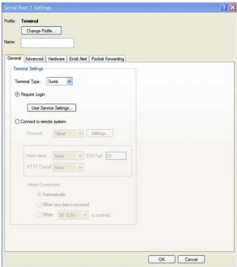
text_image
Serial Port 1 Settings Profile: Terminal Change Profile... Name: General Advanced Hardware Email Alert Packet Forwarding Terminal Settings Terminal Type: Dumb Require Login User Service Settings... Connect to remote system: Protocol Telnet Settings... Host name: None TCP Port 23 HTTP Tunnel None Initiate Connection: Automatically When any data is received WhenClick the Change Profile button to select a different serial port profile if you don't want the displayed profile:
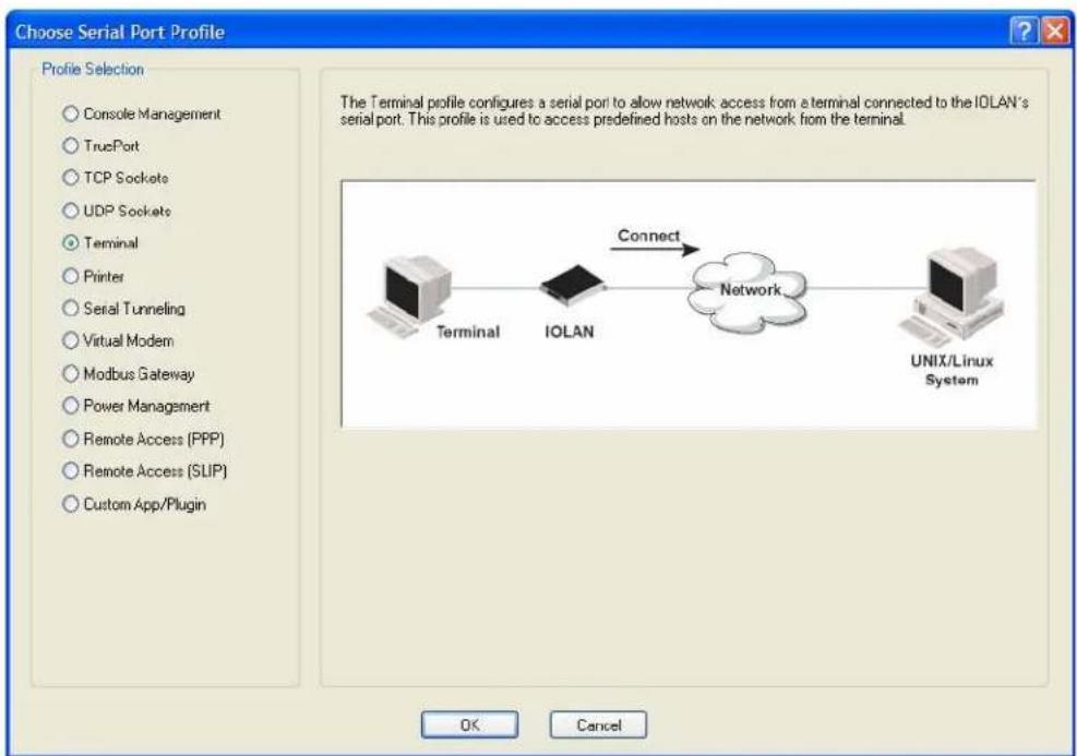
text_image
Choose Serial Port Profile Profile Selection Console Management TruePort TCP Sockets UDP Sockets Terminal Printer Serial Tunneling Virtual Modem Modbus Gateway Power Management Remote Access (PPP) Remote Access (SLIP) Custom App/Plugin The Terminal profile configures a serial port to allow network access from a terminal connected to the IOLAN's serial port. This profile is used to access predefined hosts on the network from the terminal. Terminal IOLAN Connect Network UNIX/Linux System OK CancelAs you select the different serial port profiles, a short description and a picture representing a typical application of the profile is displayed. When you have selected the appropriate profile for the serial port, click OK and those serial port profile configuration options will be displayed.
Copying a Serial Port
Once you configure a serial port, you can copy the serial port settings to other serial ports by selecting a serial port and then clicking the Copy button on the Serial Ports Settings window.
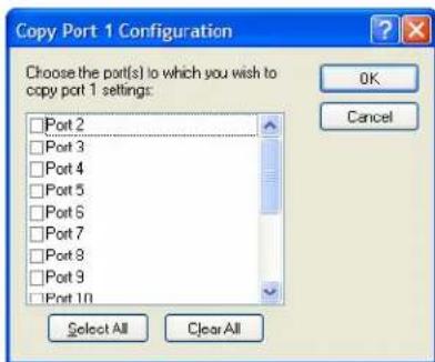
text_image
Copy Port 1 Configuration Choose the port(s) to which you wish to copy port 1 settings: Port 2 Port 3 Port 4 Port 5 Port 6 Port 7 Port 8 Port 9 Port 10 OK Cancel Select All Clear AllResetting a Serial Port
When you change a serial port's configuration, you can download the configuration file to the IOLAN and then reset a specific serial port(s) to see how you change affects the serial port's behavior. To reset a serial port, select Tools, Reset, Serial Port(s).
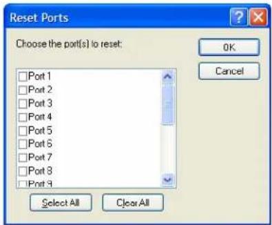
text_image
Reset Ports Choose the port(s) to reset: Port 1 Port 2 Port 3 Port 4 Port 5 Port 6 Port 7 Port 8 Port 9 OK Cancel Select All Clear AllSerial Port Profiles
Common Tabs
Overview
There are several functions that are common to more than one profile. These functions are:
- Hardware—Configure the physical serial line parameters. See Hardware Tab Field Descriptions
- Email Alert—Configure email alerts for the serial line (these can also be configured globally for all lines under the System settings). See Email Alert Tab Field Descriptions.
- Packet Forwarding—Configure data packet parameters. See Packet Forwarding Tab Field Descriptions.
- SSL/TLS—Configure SSL/TLS encryption options for the serial port. See SSL/TLS Settings Tab Field Descriptions.
Hardware Tab Field Descriptions
The Hardware tab configures all the serial port hardware connection information. The window below shows an SDS1 model; your Hardware tab might display a subset of the parameters described, depending on the IOLAN model and supported hardware.
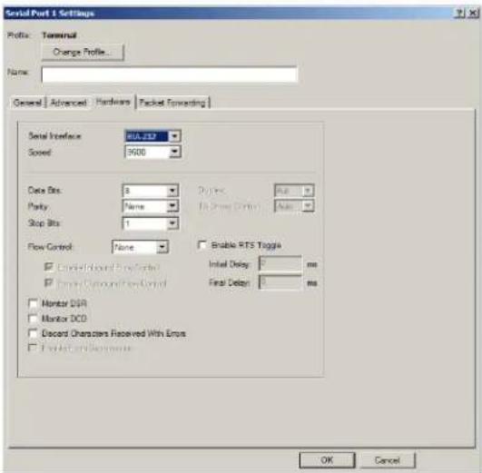
text_image
Serial Port 1 Settings Profile: Terminal Change Profile... Name: General Advanced Hardware Packet Forwarding Serial Interface BIA.332 Speed: 9000 Data Bits: 8 Parity: Name Stop Bits: 1 Flow Control: None □ Continued Round Flow Control □ Continued Around Flow Control □ Monitor DDR □ Monitor DCO □ Discard Characters Received With Errors □ Forward Connection Data Bus (Driver) Auto Enable RTS Toggle Initial Delay: 0 ms Final Delay: 0 ms OK CancelConfigure the following parameters:
Serial Interface Specifies the type of serial line that is being used with the IOLAN.
Data Options: EIA-232, EIA-422, or EIA-485.
SCS/STS/MDC models support only EIA-232.
Default: EIA-232
Speed Specifies the baud rate of the serial line; keep in mind that speed is affected by the length of the cable. You can also specify a custom baud rate. When you enter a custom baud rate, the IOLAN will calculate the closest baud rate available to the hardware. The exact baud rate calculated can be viewed in the Serial Ports statistics.
Range: 50-230400, custom supports 50-1843200 (Note: IOLAN W models support baud rates 300-1843200
Default: 9600
Data Bits Specifies the number of bits in a transmitted character.
Default: 8
Parity Specifies the type of parity being used for the data communication on the serial port. If you want to force a parity type, you can specify Mark for 1or Space for 0.
Data Options: Even, Odd, Mark, Space, None
Default: None
Stop Bits Specifies the number of stop bits that follow a byte.
Data Options: 1,1.5, 2.1.5 is only available on the 1-port and 2-port models, but not on the modem line (Serial Port 2) of the SDS1M model.
Default: 1
| Duplex | Used with a EIA-485 serial interface, specify whether the serial port is Full Duplex (communication both ways at the same time) or Half Duplex (communication in one direction at a time).Default: Full |
| TX Driver Control | Used with a EIA-485 serial interface, if your application supports RTS (Request To Send), select this option. Otherwise, select Auto.Default: Auto |
| Flow Control | Defines whether the data flow is handled by the software (Soft), hardware (Hard), Both, or None. If you are using SLIP, set to Hard only. If you are using PPP, set to either Soft or Hard (Hard is recommended). If you select Soft with PPP, you must set the ACCM parameter when you configure PPP for the Serial Port.Data Options: Soft, Hard, Both, NoneDefault: None |
| Enable RTS Toggle | Configure the Toggle RTS Feature if your application needs for RTS to be raised during character transmission.Initial delay: configure the time (in ms) between the time the RTS signal is raised and the start of character transmission. This delay only applies if this port is not running hardware flow control. If hardware flow control is used, the transmission will occur as soon as CTS is raised by the modem.Final delay: configure the time (in ms) between the time of character transmission and when RTS is dropped.Initial delay range: 0-1000 msFinal delay range: 0-1000 msDefault: Off |
| Enable Inbound Flow Control | Determines if input flow control is to be used.Default: Enabled |
| Enable Outbound Flow Control | Determines if output flow control is to be used.Default: Enabled |
| Monitor DSR Specifies whether the EIA-232 signal DSR (Data Set Ready) should be monitored. This is used with modems or any device that sends a DSR signal. When it is monitored and the IOLAN detects a DSR signal, the serial port profile is started. The Monitor DSR parameter is not available for medical unit models. If both Monitor DCD and Monitor DSR are enabled, both signals must be detected before the serial port profile is started.Default: Disabled | |
| Monitor DCD | Specifies whether the EIA-232 signal DCD (Data Carrier Detect) should be monitored. This is used with modems or any other device that sends a DCD signal. When it is monitored and the IOLAN detects a DCD signal, the serial port profile is started. If both Monitor DCD and Monitor DSR are enabled, both signals must be detected before the serial port profile is started.Default: Disabled |
| Discard Characters Received with Errors | When enabled, the IOLAN will discard characters received with a parity or framing error.Default: Disabled |
Enable Echo Suppression
This parameter applies only to EIA-485 Half Duplex mode. All characters will be echoed to the user and transmitted across the serial ports. Some EIA-485 applications require local echo to be enabled in order to monitor the loopback data to determine that line contention has occurred. If your application cannot handle loopback data, echo suppression should be enabled.
Default: Disabled
Enable Line Termination
Used with EIA-422 and EIA-485 on SDS 8-port, 16-port and 32 port rack mount IOLAN models, specifies whether or not the line is terminated; use this option when the serial port is connected to a device at the end of the serial network.
Default: Disabled
Email Alert Tab Field Descriptions
Email notification can be set at the Server and/or serial port levels. You can set unique email notifications for each serial port because the person who administers the IOLAN might not be the same person who administers the serial device(s) attached to the IOLAN port. Therefore, email notification can be sent to the proper person(s) responsible for the hardware.
The following event triggers an email notification on the Serial Port for the specified Level:
• DSR signal loss, Warning Level
• I/O alerts, Critical Level
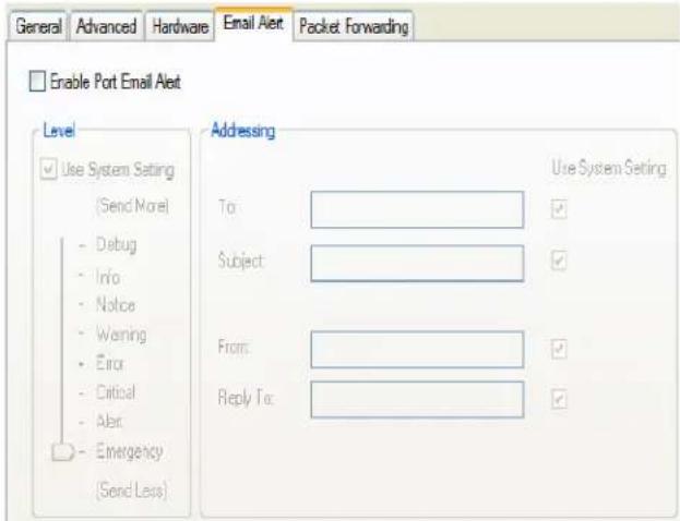
text_image
General Advanced Hardware Email Alert Packet Forwarding Enable Port Email Alert Level Use System Setting (Send Note) Debug Info Notice Warning Error Critical Alert Emergency (Send Less) Addressing To: Subject: From: Reply To: Use System Setting Use System SettingConfigure the following parameters:
Enable Port Email Alert
Enable/disable email alert settings for this serial port.
Default: Disabled
Use System Email Alert Settings
Determines whether you want the Serial Port to inherit the Email Alert settings from the System Email Alert configuration. If this is enabled, System and Serial Port notification events will have the same Email Alert setting.
Default: Enabled
Level
Choose the event level that triggers an email notification.
Data Options: Emergency, Alert, Critical, Error, Warning, Notice, Info, Debug Default: Emergency
Use System Setting By default, the fields are populated with the "global email" parameters. If you wish to override a field you must uncheck this field.
To An email address or list of email addresses that will receive the email notification.
Subject A text string, which can contain spaces, that will display in the Subject field of the email notification.
From This field can contain an email address that might identify the IOLAN name or some other value.
Reply To The email address to whom all replies to the email notification should go.
Packet Forwarding Tab Field Descriptions
The Packet Forwarding tab can be used to control/define how and when serial port data packets are sent from the IOLAN to the network.
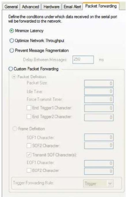
text_image
Define the conditions under which data received on the serial port will be forwarded to the network: Minimize Latency Optimize Network Throughput Prevent Message Fragmentation Delay Between Messages: 250 ms Custom Packet Forwarding Packet Definition Packet Size: 0 Idle Time: 0 Force Transmit Timer: 0 End Trigger1 Character: 0 End Trigger2 Character: 0 Frame Definition SOF1 Character: 0 SOF2 Character: 0 Transmit SOF Character(s): EOF1 Character: 0 EOF2 Character: 0 Trigger Forwarding Rule: TriggerConfigure the following parameters:
Minimize Latency This option ensures that all application data is immediately forwarded to the serial device and that every character received from the device is immediately sent on the network. Select this option for timing-sensitive applications.
Default: Enabled
Optimize Network Throughput This option provides optimal network usage while ensuring that the application performance is not compromised. Select this option when you want to minimize overall packet count, such as when the connection is over a WAN.
Default: Disabled
| Prevent Message Fragmentation | This option detects the message, packet, or data blocking characteristics of the serial data and preserves it throughout the communication. Select this option for message-based applications or serial devices that are sensitive to inter-character delays within these messages.Default: Disabled |
| Delay Between Messages | The minimum time, in milliseconds, between messages that must pass before the data is forwarded by the IOLAN.Range: 0-65535Default: 250 ms |
| Custom Packet Forwarding | This option allows you to define the packet forwarding rules based on the packet definition or the frame definition.Default: Disabled |
| Packet Definition | When enabled, this group of parameters allows you to set a variety of packet definition options. The first criteria that is met causes the packet to be transmitted. For example, if you set aForce Transmit Timerof 1000ms and a Packet Sizeof 100bytes, whichever criteria is met first is what will cause the packet to be transmitted.Default: Enabled |
| Packet Size | The number of bytes that must be received from the serial port before the packet is transmitted to the network. A value of zero (0) ignores this parameter.Range: 0-1024 bytesDefault: 0 |
| Idle Time The amount of time, in milliseconds, that must elapse between characters before the packet is transmitted to the network. A value of zero (0) ignores this parameter.Range: 0-65535 msDefault: 0 | |
| Enable Trigger1 Character | When enabled, specifies the character that when received will define when the packet is ready for transmission. The actual transmission of the packet is based on the Trigger Forwarding Rule.Range: hexadecimal 0-FFDefault: 0 |
| Enable Trigger2 Character | When enabled, creates a sequence of characters that must be received to specify when the packet is ready for transmission (if the End Trigger1 character is not immediately followed by the End Trigger2 character, the IOLAN waits for another End Trigger1 character to start the End Trigger1/End Trigger2 character sequence). The actual transmission of the packet is based on the Trigger Forwarding Rule.Range: hexadecimal 0-FFDefault: 0 |
| Frame Definition | When enabled, this group of parameters allows you to control the frame that is transmitted by defining the start and end of frame character(s). If the internal buffer (1024 bytes) is full before the EOF character(s) are received, the packet will be transmitted and the EOF character(s) search will continue.Default: Disabled |
| SOF1 Character | When enabled, the Start of Frame character defines the first character of the frame, any character(s) received before the Start of Frame character is ignored. Range: hexadecimal 0-FF Default: 0 |
| SOF2 Character | When enabled, creates a sequence of characters that must be received to create the start of the frame (if the SOF1 character is not immediately followed by the SOF2 character, the IOLAN waits for another SOF1 character to start the SOF1/SOF2 character sequence). Range: hexadecimal 0-FF Default: 0 |
| Transmit SOF Character(s) | When enabled, the SOF1 or SOF1/SOF2 characters will be transmitted with the frame. If not enabled, the SOF1 or SOF1/SOF2 characters will be stripped from the transmission. Default: Disabled |
| EOF1 Character | Specifies the End of Frame character, which defines when the frame is ready to be transmitted. The actual transmission of the frame is based on the Trigger Forwarding Rule. Range: hexadecimal 0-FF Default: 0 |
| EOF2 Character | When enabled, creates a sequence of characters that must be received to define the end of the frame (if the EOF1 character is not immediately followed by the EOF2 character, the IOLAN waits for another EOF1 character to start the EOF1/EOF2 character sequence), which defines when the frame is ready to be transmitted. The actual transmission of the frame is based on the Trigger Forwarding Rule. Range: hexadecimal 0-FF Default: 0 |
| Trigger Forwarding Rule | Determines what is included in the Frame (based on the EOF1 or EOF1/EOF2) or Packet (based on Trigger1 or Trigger1/Trigger2). Choose one of the following options: Strip-Trigger—Strips out the EOF1, EOF1/EOF2, Trigger1, or Trigger1/Trigger2, depending on your settings. Trigger—Includes the EOF1, EOF1/EOF2, Trigger1, or Trigger1/Trigger2, depending on your settings. Trigger+1—Includes the EOF1, EOF1/EOF2, Trigger1, or Trigger1/Trigger2, depending on your settings, plus the first byte that follows the trigger. Trigger+2—Includes the EOF1, EOF1/EOF2, Trigger1, or Trigger1/Trigger2, depending on your settings, plus the next two bytes received after the trigger. Default: Trigger |
SSL/TLS Settings Tab Field Descriptions
You can create an encrypted connection using SSL/TLS for the following profiles: TruePort, TCP Sockets, Terminal (the user's Service must be set to SSL_Raw), Serial Tunneling, Virtual Modem, and Modbus. When you enable this feature, it will automatically use the global SSL/TLS settings (configured on Security, SSL/TLS), although you can configure unique SSL/TLS settings for the serial port.
When configuring SSL/TLS, the following configuration options are available:
- You can set up the IOLAN to act as an SSL/TLS client or server.
- There is an extensive selection of SSL/TLS ciphers that you can configure for your SSL/TLS connection; see Appendix B, SSL/TLS Ciphers on page 310 for a list of SSL/TLS ciphers.
Some combinations of cipher groups are not available on FIPS firmware versions.
- You can enable peer certificate validation, for which you must supply the validation criteria that was used when creating the peer certificate (this is case sensitive, so keep that in mind when enabling and configuring this option).
Note: See Keys and Certificates for information about SSL/TLS support documents.
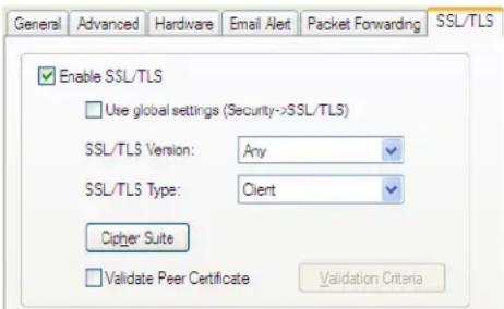
text_image
General Advanced Hardware Email Alert Packet Forwarding SSL/TLS Enable SSL/TLS Use global settings (Security->SSL/TLS) SSL/TLS Version: Any SSL/TLS Type: Client Cipher Suite Validate Peer Certificate Validation CriteriaConfigure the following parameters:
Enable SSL/TLS Activates the SSL/TLS settings for the serial port.
Default: Disabled
Use global settings Uses the SSL/TLS settings configured in the Security section for the serial port.
Default: Enabled
SSL/TLS Version Specify whether you want to use:
- Any—The IOLAN will try a TLSv1 connection first. If that fails, it will try an SSLv3 connection. If that fails, it will try an SSLv2 connection.
- SSLv3—The connection will use only SSLv3.
- TLSv1—The connection will use only TLSv1.
- TLSv1.1—The connection will use only TLSv1.1.
- TLSv1.2—The connection will use only TLSv1.2.
Default: Any
SSL/TLS Type Specify whether the IOLAN serial port will act as an SSL/TLS client or server.
Default: Client
Cipher Suite Button Click this button to specify SSL/TLS connection ciphers.
See Cipher Suite Field Descriptions for more information.
Validate Peer Certificate
Enable this option when you want the Validation Criteria to match the Peer Certificate for authentication to pass. If you enable this option, you need to download an SSL/TLS certificate authority (CA) list file to the IOLAN.
Default: Disabled
Validation Criteria Button
Click this button to create peer certificate validation criteria that must be met for a valid SSL/TLS connection.
See Validation Criteria Field Descriptions for more information.
Cipher Suite Field Descriptions
The SSL/TLS cipher suite is used to encrypt data between the IOLAN and the client. You can specify up to five cipher groups.
Some combinations of cipher groups may not be available on some firmware versions.
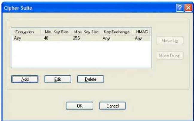
text_image
Cipher Suite Encryption Min. Key Size Max. Key Size Key Exchange HMAC Any 40 256 Any Any Move Up Move Down Add Edit Delete OK CancelThe following buttons are available on this window:
Add Button
Adds a cipher to the cipher list.
Edit Button
Edits a cipher in the cipher list.
Delete Button
Deletes a cipher from the cipher list.
Move Up Button
Moves a cipher up in preference in the cipher list.
Move Down Button
Moves a cipher down in preference in the cipher list.
Adding/Editing a Cipher Suite
To see a list of valid cipher suite combinations, see Appendix B, SSL/TLS Ciphers on page 310.
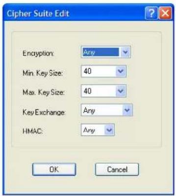
text_image
Cipher Suite Edit Encryption: Any Min. Key Size: 40 Max. Key Size: 40 Key Exchange: Any HMAC: Any OK CancelConfigure the following parameters:
| Encryption | Select the type of encryption that will be used for the SSL connection. Data Options: Any—Will use the first encryption format that can be negotiated. AES 3DES DES ARCFOUR ARCTWO AES-GCM Default:Any |
| Min Key Size | The minimum key size value that will be used for the specified encryption type. Data Options:40,56,64,128,168,256 Default:40 |
| Max Key Size | The maximum key size value that will be used for the specified encryption type. Data Options:40,56,64,128,168,256 Default:256 |
Key Exchange
The type of key to exchange for the encryption format.
Data Options:
- Any—Any key exchange that is valid is used (this does not, however, include ADH keys).
• RSA—This is an RSA key exchange using an RSA key and certificate. - EDH-RSA—This is an EDH key exchange using an RSA key and certificate.
- EDH-DSS—This is an EDH key exchange using a DSA key and certificate.
- ADH—This is an anonymous key exchange which does not require a private key or certificate. Choose this key if you do not want to authenticate the peer device, but you want the data encrypted on the SSL/TLS connection.
- ECDH-ECDSA—This is an ECDH key exchange using a ECDSA key and certificate.
Default: Any
HMAC
Select the key-hashing for message authentication method for your encryption type.
Data Options:
Any
MD5
SHA1
SHA256
SHA384
Default: Any
Validation Criteria Field Descriptions
If you choose to configure validation criteria, the information in the peer SSL/TLS certificate must match exactly the information configured in this window in order to pass peer authentication and create a valid SSL/TLS connection.
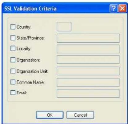
text_image
SSL Validation Criteria □ Country: □ State/Province: □ Locality: □ Organization: □ Organization Unit: □ Common Name: □ Email: OK CancelConfigure the following parameters:
Country
A country code; for example, US. This field is case sensitive in order to successfully match the information in the peer SSL/TLS certificate.
Data Options: Two characters
| State/Province | An entry for the state/province; for example, IL. This field is case sensitive in order to successfully match the information in the peer SSL/TLS certificate. Data Options: Maximum 128 characters |
| Locality | An entry for the location; for example, Chicago. This field is case sensitive in order to successfully match the information in the peer SSL/TLS certificate. Data Options: Maximum 128 characters |
| Organization | An entry for the organization; for example, Accounting. This field is case sensitive in order to successfully match the information in the peer SSL/TLS certificate. Data Options: Maximum 64 characters |
| Organization Unit | An entry for the unit in the organization; for example, Payroll. This field is case sensitive in order to successfully match the information in the peer SSL/TLS certificate. Data Options: Maximum 64 characters |
| Common Name An entry for common name; for example, the host name or fully qualified domain name. This field is case sensitive in order to successfully match the information in the peer SSL/TLS certificate. Data Options: Maximum 64 characters | |
| An entry for an email address; for example, acct@anycompany.com. This field is case sensitive in order to successfully match the information in the peer SSL/TLS certificate. Data Options: Maximum 64 characters |
Console Management Profile
Overview
The Console Management profile provides access through the network to a console or administrative port of a server or router attached to the IOLAN's serial port. This profile configures the IOLAN's serial port to set up a TCP socket that will listen for a Telnet or SSH connection from the network.
Functionality
Use the Console Management profile when you are configuring users who need to access a serial console port from the network.
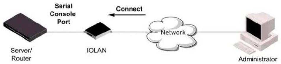
flowchart
graph LR
    A["Server/Router"] --> B["Serial Console Port"]
    B --> C["IOLAN"]
    C --> D["Network"]
    D --> E["Administrator"]
    style A fill:#000,stroke:#fff,color:#fff
    style E fill:#000,stroke:#fff,color:#fff
    linkStyle 0 stroke:#000,stroke-width:2px
    linkStyle 1 stroke:#000,stroke-width:2px
    linkStyle 2 stroke:#000,stroke-width:2px
    linkStyle 3 stroke:#000,stroke-width:2px
    linkStyle 4 stroke:#000,stroke-width:2px
    linkStyle 5 stroke:#000,stroke-width:2px
    linkStyle 6 stroke:#000,stroke-width:2px
    linkStyle 7 stroke:#000,stroke-width:2px
    linkStyle 8 stroke:#000,stroke-width:2px
    linkStyle 9 stroke:#000,stroke-width:2px
    linkStyle 10 stroke:#000,stroke-width:2px
    linkStyle 11 stroke:#000,stroke-width:2px
    linkStyle 12 stroke:#000,stroke-width:2px
    linkStyle 13 stroke:#000,stroke-width:2px
    linkStyle 14 stroke:#000,stroke-width:2px
    linkStyle 15 stroke:#000,stroke-width:2px
    linkStyle 16 stroke:#000,stroke-width:2px
    linkStyle 17 stroke:#000,stroke-width:2px
    linkStyle 18 stroke:#000,stroke-width:2px
    linkStyle 19 stroke:#000,stroke-width:2px
    linkStyle 20 stroke:#000,stroke-width:2px
General Tab Field Descriptions
The Console Management General tab configures how the serial port will be accessed by the user through the network.
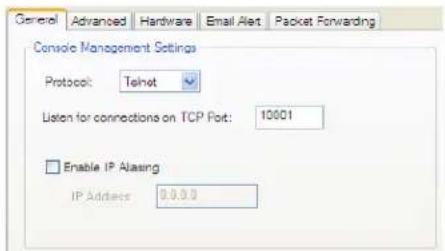
text_image
General Advanced Hardware Email Alert Packet Forwarding Console Management Settings Protocol: Telnet Listen for connections on TCP Port: 10001 Enable IP Alasing IP Address: 0.0.0.0Configure the following parameters:
Protocol Specify the connection method that users will use to communicate with a serial device connected to the IOLAN through the network.
Data Options: Telnet, SSH
Default: Telnet
Listen for The port number that the IOLAN will listen on for incoming TCP connections.
Connections on TCP Port Default: 10001, depending on the serial port number
Enable IP Aliasing Enables/disables the ability to access a serial device connected to the serial port by an IP address (or host name that can be resolved to the Internet Address in a DNS network) instead of the IOLAN's IP address and port number.
Default: Disabled
IP Address
Users can access serial devices connected to the IOLAN through the network by the specified Internet Address (or host name that can be resolved to the Internet Address in a DNS network).
Field Format: IPv4 or IPv6 Address
Advanced Tab Field Descriptions
The Console Management Advanced tab configures serial port options that may be required by certain applications.
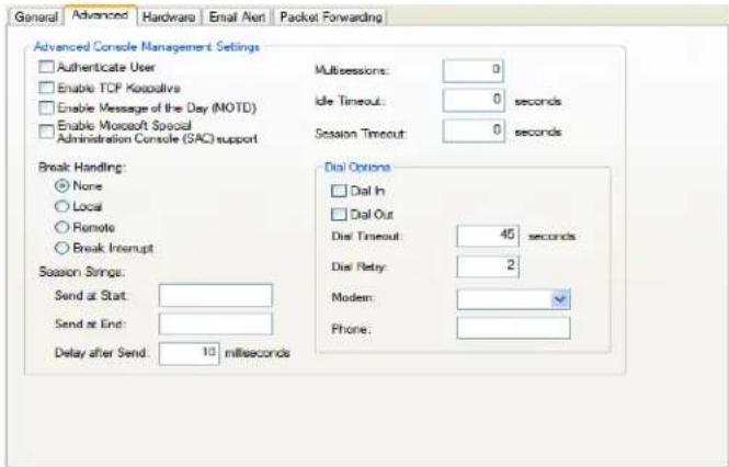
text_image
General Advanced Hardware Email Net Packet Forwarding Advanced Console Management Settings Authenticate User Enable TCP Kosovo Enable Message of the Day (MOTD) Enable Microsoft Social Administration Console (SAC) support Break Handling: None Local Remote Break Interrupt Session Strings: Send at Start: Send at End: Delay after Send: 10 milliseconds Multisections: 0 Idle Timeout: 0 seconds Session Timeout: 0 seconds Dial Options Dial In Dial Out Dial Timeout: 45 seconds Dial Retay: 2 Modem: Phone:Configure the following parameters:
Authenticate User Enables/disables login/password authentication for users connecting from the network.
Default: Disabled
Enable TCP Keepalive Enables a per-connection TCP keepalive feature. After the configured number of seconds, the connection will send a gratuitous ACK to the network peer, thus either ensuring the connection stays active OR causing a dropped connection condition to be recognized.
This parameter needs to be used in conjunction with Monitor Connection Status Interval parameter found in the Serial, Advanced, Advanced Settings tab. The interval specifies the inactivity period before "testing" the connection.
Default: Disabled
Enable Message of the Day (MOTD) Enables/disables the display of the message of the day. Default: Disabled
Enable Microsoft Special Administrator Console (SAC) When enabled, a user can access SAC (the interface of the Microsoft Emergency Management Systems utility) through EasyPort Web when the IOLAN's serial port is connected to a Microsoft Server 2003 or Microsoft Server 2008 host.
support Default: Disabled
Multisessions
The number of extra network connections available on a serial port, in addition to the single session that is always available. Enabling multisessions will permit multiple users to monitor the same console port. Each user monitoring the port can be assigned different privileges to this port.
Range: Dependent on model:
1-port: 0
• 2-port: (4 x #-of-ports) -1
STS/SDS 4+ ports: (2 x #-of-ports) -1
• SCS 4+ ports: (2 x (#-of-ports + 1)) -1
Default: 0
Idle Timeout
Use this timer to close a connection because of inactivity. When the Idle Timeout expires, the IOLAN will end the connection.
Range: 0-4294967 seconds (about 49 days)
Default: 0 seconds so the port will never timeout
Session Timeout
Use this timer to forcibly close the session/connection when the Session Timeout expires.
Default: 0 seconds so the port will never timeout
Range: 0-4294967 seconds (about 49 days)
Break Handling Specifies how a break is interpreted.
Data Range:
- None—The IOLAN ignores the break key completely and it is not passed through to the host.
- Local—The IOLAN deals with the break locally. If the user is in a session, the break key has the same effect as a hot key.
- Remote—When the break key is pressed, the IOLAN translates this into a telnet break signal which it sends to the host machine.
- Break Interrupt—On some systems such as SunOS, XENIX, and AIX, a break received from the peripheral is not passed to the client properly. If the client wishes to make the break act like an interrupt key (for example, when the stty options -ignbrk and brkintr are set).
Default: None
Session Strings
Controls the sending of ASCII strings to serial devices at session start and session termination as follows;
- Send at Start - If configured, this string will be sent to the serial device on power-up of the IOLAN, or when a kill line command is issued on this serial port. If the "monitor DSR" or "monitor DCD" options are set, the string will also be sent when the monitored signal is raised.
Range: 0-127 alpha-numeric characters. Non printable ascii characters must be entered in this format <027>. The decimal numbers within the brackets must be 3 digits long (example 003 not 3).
- Send at End - If configured, this string will be sent to the serial device when the TCP session on the LAN is terminated. If multihost is configured, this string will only be send in listen mode to the serial device when all multihost connections are terminated.
Range: 0-127 alpha-numeric characters. Non printable ascii characters must be entered in this format <027>. The decimal numbers within the brackets must be 3 digits long (example 003 not 3).
- Delay after Send—If configured, a delay time is sent to the device. This delay can be used to provide the serial device with time to process the string before the session is initiated.
Range: 0-65535 ms
Default: 10 ms
Dial In If the console port is remote and will be dialing in via modem or ISDN TA, enable this parameter.
Default: Disabled
Dial Out
If you want the modem to dial a number when the serial port is started, enable this parameter.
Default: Disabled
Dial Timeout
The number of seconds the IOLAN will wait to establish a connection to a remote modem.
Range: 1-99
Default: 45 seconds
Dial Retry
The number of times the IOLAN will attempt to re-establish a connection with a remote modem.
Range: 0-99
Default: 2
Modem The name of the predefined modem that is used on this line.
Phone
The phone number to use when Dial Out is enabled.
TruePort Profile
Overview
TruePort is especially useful when you want to improve data security, as you can enable an SSL/TLS connection between the TruePort host port and the IOLAN. TruePort is COM Port redirector that is supplied with the IOLAN. TruePort can be installed as a client on a Workstation or Server and supports a variety of operating systems. It, in conjunction with the IOLAN, emulates a local serial port (COM port), to the application, to provide connectivity to a remote serial device over the network. The TruePort profile operates in conjunction with the TruePort software.
Functionality
TruePort is a COM port redirector utility for the IOLAN. It can be run in two modes (these modes will be set on the client software when it is configured):
- TruePort Full mode—This mode allows complete device control and operates as if the device was directly connected to the Workstation/Server's local serial port. It provides a complete COM port interface between the attached serial device and the network. All serial controls, baud rate control, etc., are sent to the IOLAN and replicated on its associated serial port.
- TruePort Lite mode—This mode provides a simple raw data interface between the application and the remote serial port. Although the port will still operate as a COM port, control signals are ignored. In this mode, the serial communications parameters must be configured on the IOLAN.
See the TruePort User's Guide for more details about the TruePort client software.
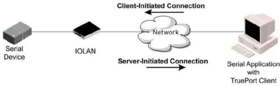
flowchart
graph LR
    A["Serial Device"] --> B["IOLAN"]
    B --> C["Server-Initiated Connection"]
    C --> D["Client-Initiated Connection"]
    D --> E["Network"]
    E --> F["Serial Application with TruePort Client"]
General Tab Field Descriptions
The TruePort General tab determines how the TruePort connection is initiated and then sets up the appropriate connection parameters.
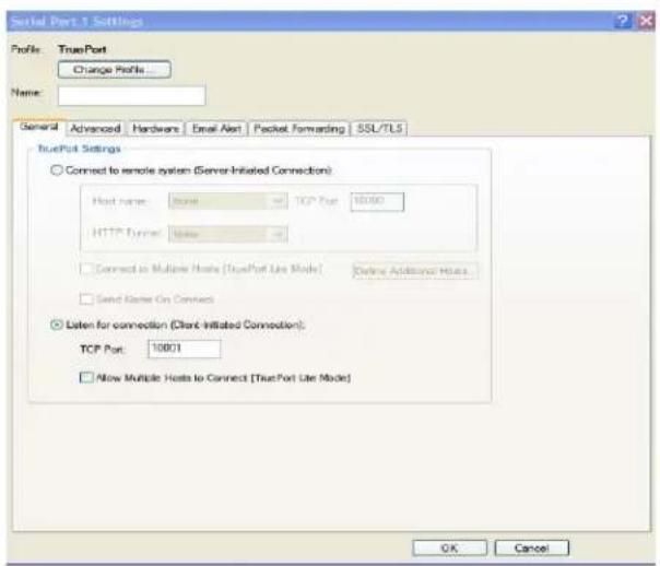
text_image
Serial Port 1 Settings Profile: TruePort Change Profile... Name: General Advanced Hardware Email Alert Packet Forwarding SSL/TLS TruePort Settings Connect to remote system (Server-Initiated Connection) Host name: None TCP Port: 10000 HTTP Tunnel: None Connect to Multiple Hosts (TruePort Use Mode) Online Additional Hosts Send Home On Connects Listen for connection (Client-Initiated Connection): TCP Port: 10001 Allow Multiple Hosts to Connect (TruePort Lite Mode) OK CancelConfigure the following parameters:
Connect to remote system When enabled, the IOLAN initiates communication to the TruePort client. Default: Enabled
Host Name The configured host that the IOLAN will connect to (must be running TruePort). Default: None
TCP Port The TCP Port that the IOLAN will use to communicate through to the TruePort client. Default: 10001 for serial port 1, then increments by one for each serial port
HTTP Tunnel Specify the HTTP tunnel to be used for this connection.
Connect to Multiple Hosts When enabled, the IOLAN will establish a connection to multiple clients (Hosts). When using the multiple hosts feature, all TruePort clients must be running in Lite mode. Default: Disabled
Send Name on Connect When enabled, the port name will be sent to the host upon session initiation. This will be done before any other data is sent or received to/from the host. Default: Disabled
Define Additional Hosts Button Click this button to define the hosts that this serial port will connect to. This button is also used to define the Primary/Backup host functionality. See Adding/Editing Additional TruePort Hosts for more information.
Listen for Connection When enabled, the IOLAN will wait for connections to be initiated by the TruePort Client. Default: Disabled
TCP Port The TCP Port that the IOLAN will use to communicate through to the TruePort client. Default: 10001 for serial port 1, then increments by one for each serial port
Allow Multiple Hosts to Connect
When this option is enabled, multiple hosts can connect to a serial device that is connected to this serial port. Note: These multiple clients (Hosts) need to be running TruePort in Lite mode.
Default: Disabled
Adding/Editing Additional TruePort Hosts
You can define a list of hosts that the serial device will communicate to through TruePort Lite or a primary/backup host.
Configure the following parameters:
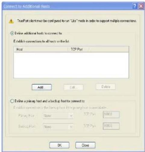
text_image
Connect to Additional Hosts TruePort client must be configured to run "Libs" mode in order to support multiple connections. Define additional hosts to connect to: Establish connections to all hosts on the list. Host TOP Port Add Cell Delete Define a primary host and a backup host to connect to: Establish connections to the backup host if the primary host is metable. Primary Port None TCP (PU) 10000 Backup Port None TCP (PU) 10000 OK CloseDefine additional hosts to connect to
When this option is enabled, you can define up to 49 hosts that the serial device connected to this serial port will attempt communicate to. With this mode of operation, the IOLAN will connect to multiple hosts simultaneously.
Default: Enabled
Add Button
Click the Add button to add a host to the list of hosts that will be receiving communication from the serial device connected to the IOLAN.
See Adding/Editing a Multihost Entry for more information.
Edit Button
Highlight an existing host and click the Edit button to edit a host in the list of hosts that will be receiving communication from the serial device connected to the IOLAN.
Delete Button
Highlight an existing host and click the Edit button to edit a host in the list of hosts that will be receiving communication from the serial device connected to the IOLAN.
Define a primary host and backup...
When this option is enabled, you need to define a primary host that the serial device connected to this serial port will communicate to and a backup host, in the event that the IOLAN loses communication to the primary host. The IOLAN will first establish a connection to the primary host. Should the connection to the primary host be lost (or never established), the IOLAN will establish a connection the backup host. Once connected to the backup, the IOLAN will attempt to re-establish a connection to the Primary host, once this is successfully done, it gracefully shuts down the backup connection.
Default: Disabled
| Primary Host | Specify a preconfigured host that the serial device will communicate to through the IOLAN.Default: None |
| TCP Port | Specify the TCP port that the IOLAN will use to communicate to the Primary HostDefault: 0 |
| Backup Host | Specify a preconfigured host that the serial device will communicate to through the IOLAN if the IOLAN cannot communicate with the Primary Host.Default: None |
| TCP Port | Specify the TCP port that the IOLAN will use to communicate to the Backup HostDefault: 10000 |
Adding/Editing a Multihost Entry
When you click the Add or Edit button, the Host Entry window appears. The hosts in the multihost list must already be defined. If you add a host that was defined with its fully qualified domain name (FQDN), it must be resolvable by your configured DNS server.
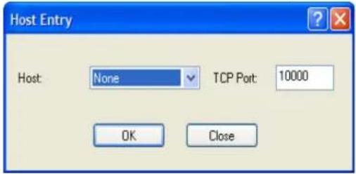
text_image
Host Entry Host: None TCP Port: 10000 OK CloseHost Name Specify the preconfigured host that will be in the multihost list. Default: None
TCP Port Specify the TCP port that the IOLAN will use to communicate to the Primary Host Default: 10000 + serial port number - 1 (so serial port 47 defaults to 10046)
Advanced Tab Field Descriptions
The TruePort Advanced tab determines how the TruePort connection is initiated and then sets up the appropriate connection parameters.
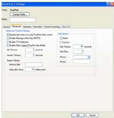
text_image
Serial Port 1 Settings Profile: TruePort Change Profile Name: Genera Advanced Hardware Email Alert Packet Forwarding SSL/TLS Advanced TruePort Settings Signals high when not under TruePort client control Enable Message of the Day (MOTO) Enable TCP Keepalive Enable Data Logging (TruePort Lite Mode) Life Timeout: 0 seconds Session Timeout: 0 seconds Session Strings: Send at Start: Delay after Send: 10 milliseconds Dial Options Dial In Dial Out Dial Timeout: 45 seconds Dial Retry: 2 Modem: Phone: OK CancelConfigure the following parameters:
Signals high when...
This option has the following impact based on the state of the TruePort connection:
- TruePort Lite Mode—When enabled, the EIA-232 signals remain active before, during, and after the TruePort connection is established. When disabled, the EIA-232 signals remain inactive during and after the Trueport connection is established.
- TruePort Full Mode—When enabled, the EIA-232 signals remain active before and after the TruePort connection and the TruePort client will control the state of the signals during the established TruePort connection. When disabled, the EIA-232 signals remain inactive before and after the TruePort connection and the TruePort client will control the state of the signals during the established TruePort connection.
Default: Enabled
Enable Message of the Day (MOTD)
Enables/disables the display of the message of the day.
Default: Disabled
Enable TCP Keepalive
Enables a per-connection TCP keepalive feature. After the configured number of seconds, the connection will send a gratuitous ACK to the network peer, thus either ensuring the connection stays active OR causing a dropped connection condition to be recognized.
This parameter needs to be used in conjunction with Monitor Connection Status Interval parameter found in the Serial, Advanced, Advanced Settings tab. The interval specifies the inactivity period before "testing" the connection.
Default: Disabled
| Enable Data Logging | When enabled, serial data will be buffered if the TCP connection is lost. When the TCP connection is re-established, the buffered serial data will be sent to its destination. If using the Trueport profile, data logging is only supported in Lite Mode.The minimum data buffer size for all models is 1 KB. The maximum data buffer size is 2000 KB for DS1/TS2/STS8D, all other models are 4000 KB. If the data buffer is filled, incoming serial data will overwrite the oldest data.Values: 1-2000 KB (DS1/TS1/STS8D) - Default 4 KBValues: 1-4000 KB (all other models) - Default 256 KBDefault: DisabledNote: A kill line or a reboot of the IOLAN causes all buffered data to be lost.Some profile features are not compatible with the data logging feature. See Appendix K, Data Logging on page 464.To change the default data logging buffer size see Advanced Serial Settings Tab. |
| Idle Timeout | Use this timer to close a connection because of inactivity. When the Idle Timeout expires, the IOLAN will end the connection.Range: 0-4294967 seconds (about 49 days)Default: 0 seconds so the port will never timeout |
| Session Timeout | Use this timer to forcibly close the session/connection when the Session Timeout expires.Default: 0 seconds so the port will never timeoutRange: 0-4294967 seconds (about 49 days) |
| Session Strings | Controls the sending of ASCII strings to serial device at session start as follows;Send at Start—If configured, this string will be sent to the serial device on power-up of the IOLAN, or when a kill line command is issued on this serial port. If the "monitor DSR" or "monitor DCD" options are set, the string will also be sent when the monitored signal is raised.Range: 0-127 alpha-numeric charactersRange: hexadecimal 0-FFDelay after Send - If configured, will inset a delay after the string is sent to the device. This delay can be used to provide the serial device with time to process the string before the session is initiated.Default: 10 ms |
| Dial In If the device is remote and will be dialing in via modem or ISDN TA, enable this parameter.Default: Disabled | |
| Dial Out | If you want the modem to dial a number when the serial port is started, enable this parameter.Default: Disabled |
| Dial Timeout | The number of seconds the IOLAN will wait to establish a connection to a remote modem.Range: 1-99Default: 45 seconds |
Dial Retry The number of times the IOLAN will attempt to re-establish a connection with a remote modem.
Range: 0-99
Default: 2
Modem The name of the predefined modem that is used on this line.
Phone The phone number to use when Dial Out is enabled.
TCP Sockets Profile
Overview
The TCP Socket profile allows for a serial device to communicate over a TCP network. The TCP connection can be initiated from a host on the network and/or a serial device. This is typically used with an application on a Workstation or Server that communicates to a device using a specific TCP socket. This is often referred to as a RAW connection.
Functionality
The TCP Sockets profile permits a raw connection to be established in either direction, meaning that the connection can be initiated by either the Workstation/Server or the IOLAN.
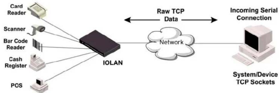
flowchart
graph LR
    A["Card Reader"] --> B["IOLAN"]
    C["Scanner"] --> B
    D["Bar Code Reader"] --> B
    E["Cash Register"] --> B
    F["POS"] --> B
    B --> G["Raw TCP Data"]
    G --> H["Incoming Serial Connection"]
    H --> I["System/Device TCP Sockets"]
    B --> J["Network"]
General Tab Field Descriptions
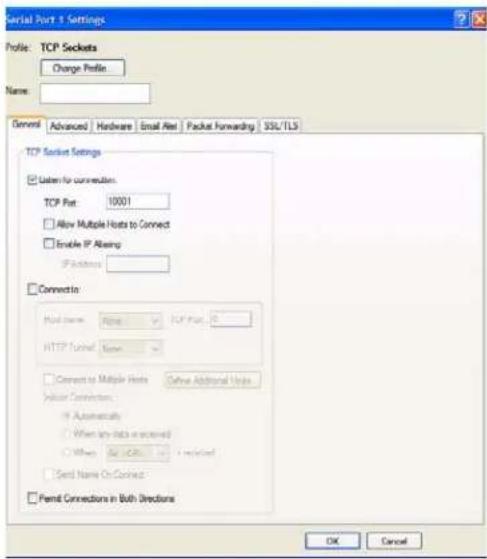
text_image
Serial Port 1 Settings Profile: TCP Sockets Change Profile Name: General Advanced Hardware Email Fax Packet Forwarding SSL/TLS TCP Socket Settings □ Listen for connection: TCP Port: 10001 □ Allow Multiple Hosts to Connect □ Enable IP Abserg IP Address □ Connects: Host name: Altire TCP Port, R HTTP Control Name □ Connect to Multiple Hosts Online Additional Hosts Vertical Connections: ○ Automatics ○ When any data is scanned ○ When OSOS - Connected □ Send Name On Connection □ Permit Connections in Both Directions OK CancelConfigure the following parameters:
Listen for
Connection
When enabled, the IOLAN listens for a connection to be established by the Workstation/Server on the network.
Default: Enabled
TCP Port The TCP port that the IOLAN will use to listen for incoming connections.
Default: 10000 plus the serial port number, so serial port 5 would have a default of 10005
HTTP Tunnel Specify the HTTP tunnel to be used for this connection.
Allow Multiple Hosts to Connect When this option is enabled, multiple hosts can connect to the serial device that is connected to this serial port.
Default: Disabled
Enable IP Aliasing Enables/disables the ability to access a serial device connected to the serial port by an IP address (or host name that can be resolved to the Internet Address in a DNS network) instead of the IOLAN's IP address and port number.
Default: Disabled
IP Address Users can access serial devices connected to the IOLAN through the network by the specified Internet Address (or host name that can be resolved to the Internet Address in a DNS network).
Field Format: IPv4 or IPv6 Address
Connect To When enabled, the IOLAN initiates communication to the Workstation/Server.
Default: Disabled
Host Name The name (resolvable via DNS) or IP address of the configured host the IOLAN will connect to.
TCP Port The TCP Port that the IOLAN will use to communicate to the client.
Default: 0
Connect to Multiple Hosts When enabled, allows a serial device connected to this serial port to communicate to multiple hosts.
Default: Disabled
Define Additional Hosts Button Click this button to define the hosts that this serial port will connect to. This button is also used to define the Primary/Backup host functionality.
Initiate Connection If the serial port hardware parameters have been setup to monitor DSR or Automatically DCD, the host session will be started once the signals are detected. If no hardware signals are being monitored, the IOLAN will initiate the session immediately after being powered up.
Default: Enabled
Initiate Connection Initiates a connection to the specified host when any data is received on the serial port. When any data is
Default: Disabled
Initiate Connection Initiates a connection to the specified host only when the specified character is received on the serial port.
Send name on Connect When enabled, the port name will be sent to the host upon session initiation. This will be done before any other data is sent or received to/from the host
Default: Disabled
| Permit | When this option is enabled, the connection can be initiated by either the |
| Connections in Both Directions | IOLAN or a host. |
| Default: Disabled |
Adding/Editing Additional Hosts
You can define a list of hosts that the serial device will communicate to or a primary/backup host.
Configure the following parameters:
| Define additional hosts to connect to | When this option is enabled, you can define up to 49 hosts that the serial device connected to this serial port will attempt communicate to. With this mode of operation, the IOLAN will connect to multiple hosts simultaneously.Default: Enabled |
| Add Button | Click the Add button to add a host to the list of hosts that will be receiving communication from the serial device connected to the IOLAN. |
| Edit Button | Highlight an existing host and click the Edit button to edit a host in the list of hosts that will be receiving communication from the serial device connected to the IOLAN. |
| Delete Button | Click the Delete button to delete a host to the list of hosts that will be receiving communication from the serial device connected to the IOLAN. |
| Define a primary host and backup... | When this option is enabled, you need to define a primary host that the serial device connected to this serial port will communicate to and a backup host, in the event that the IOLAN loses communication to the primary host. The IOLAN will first establish a connection to the primary host. Should the connection to the primary host be lost (or never established), the IOLAN will establish a connection the backup host. Once connected to the backup, the IOLAN will attempt to re-establish a connection to the Primary host, once this is successfully done, it gracefully shuts down the backup connection.Default: Disabled |
| Primary Host | Specify a preconfigured host that the serial device will communicate to through the IOLAN.Default: None |
| TCP Port | Specify the TCP port that the IOLAN will use to communicate to the Primary HostDefault: 0 |
| Backup Host | Specify a preconfigured host that the serial device will communicate to through the IOLAN if the IOLAN cannot communicate with the Primary Host.Default: None |
| TCP Port | Specify the TCP port that the IOLAN will use to communicate to the Backup Host.Default: 10000 |
Adding/Editing a Multihost Entry
When you click the Add or Edit button, the Host Entry window appears. The hosts in the multihost list must already be defined (see Host Table to learn how to create a host). If you add a host that was defined with its fully qualified domain name (FQDN), it must be resolvable by your configured DNS server.
Configure the following parameters:
Host Name
Specify the preconfigured host that will be in the multihost list.
Default: None
TCP Port
Specify the TCP port that the IOLAN will use to communicate to the Host.
Default: 0
Advanced Tab Field Descriptions
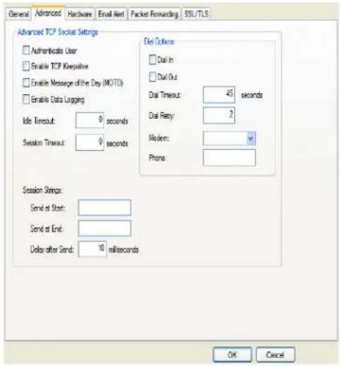
text_image
General Advanced Hardware Email Alert Packet Forwarding SSL/TLS Advanced TCP Socket Settings □ Authentbrates User □ Enable TCP Kmpulative □ Enable Message of the Day (MOTD) □ Enable Data Logging Idle Timeout: 0 seconds Session Timeout: 0 seconds Session Strings: Send at Start: Send at End: Delay after Send: 10 milliseconds Dial Options □ Dial In □ Dial Out Dial Timeout: 45 seconds Dial Retay: 2 Modern: Phone: OK CancelConfigure the following parameters:
Authenticate User
Enables/disables login/password authentication for users connecting from the network.
Default: Disabled
Enable TCP Keepalive
Enables a per-connection TCP keepalive feature. After the configured number of seconds, the connection will send a gratuitous ACK to the network peer, thus either ensuring the connection stays active OR causing a dropped connection condition to be recognized.
This parameter needs to be used in conjunction with Monitor Connection Status Interval parameter found in the Serial, Advanced, Advanced Settings tab. The interval specifies the inactivity period before "testing" the connection.
Default: Disabled
Enable Message of the Day (MOTD)
Enables/disables the display of the message of the day. Default: Disabled
Enable Data Logging
When enabled, serial data will be buffered if the TCP connection is lost. When the TCP connection is re-established, the buffered serial data will be sent to its destination. If using the Trueport profile, data logging is only supported in Lite Mode.
The minimum data buffer size for all models is 1 KB. The maximum data buffer size is 2000 KB for DS1/TS2/STS8D, all other models are 4000 KB. If the data buffer is filled, incoming serial data will overwrite the oldest data.
Values: 1-2000 KB (DS1/TS1/STS8D) - Default 4 KB
Values: 1-4000 KB (all other models) - Default 256 KB
Default: Disabled
Note: A kill line or a reboot of the IOLAN causes all buffered data to be lost.
Some profile features are not compatible with the data logging feature. See Appendix K, Data Logging on page 464.
To change the default data logging buffer size see Advanced Serial Settings Tab.
Idle Timeout
Use this timer to close a connection because of inactivity. When the Idle Timeout expires, the IOLAN will end the connection.
Range: 0-4294967 seconds (about 49 days)
Default: 0 seconds so the port will never timeout
Session Timeout
Use this timer to forcibly close the session/connection when the Session Timeout expires.
Default: 0 seconds so the port will never timeout
Range: 0-4294967 seconds (about 49 days)
Session Strings
Controls the sending of ASCII strings to serial devices at session start and session termination as follows;
- Send at Start - If configured, this string will be sent to the serial device on power-up of the IOLAN, or when a kill line command is issued on this serial port. If the "monitor DSR" or "monitor DCD" options are set, the string will also be sent when the monitored signal is raised.
Range: 0-127 alpha-numeric characters. Non printable ascii characters must be entered in this format <027>. The decimal numbers within the brackets must be 3 digits long (example 003 not 3).
- Send at End - If configured, this string will be sent to the serial device when the TCP session on the LAN is terminated. If multihost is configured, this string will only be send in listen mode to the serial device when all multihost connections are terminated.
Range: 0-127 alpha-numeric characters. Non printable ascii characters must be entered in this format <027>. The decimal numbers within the brackets must be 3 digits long (example 003 not 3).
- Delay after Send—If configured, a delay time is sent to the device. This delay can be used to provide the serial device with time to process the string before the session is initiated.
Range: 0-65535 ms
Default: 10 ms
Dial In If the device is remote and will be dialing in via modem or ISDN TA, enable this parameter.
Default: Disabled
Dial Out If you want the modem to dial a number when the serial port is started, enable this parameter.
Default: Disabled
Dial Timeout The number of seconds the IOLAN will wait to establish a connection to a remote modem.
Range: 1-99
Default: 45 seconds
Dial Retry The number of times the IOLAN will attempt to re-establish a connection with a remote modem.
Range: 0-99
Default: 2
Modem The name of the predefined modem that is used on this line.
Phone The phone number to use when Dial Out is enabled.
UDP Sockets Profile
Overview
The UDP profile configures a serial port to send or receive data to/from the LAN using the UDP protocol.
Functionality
You can use UDP profile in the following two basic modes. The first is to send data coming from the serial device to one or more UDP listeners on the LAN. The second is to accept UDP datagrams coming from one or more UDP senders on the LAN and forward this data to the serial device. You can also configure a combination of both which will allow you to send and receive UDP data to/from the LAN.
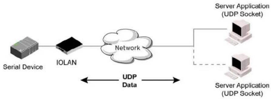
flowchart
graph LR
    A["Serial Device"] --> B["IOLAN"]
    B --> C["Network"]
    C --> D["Server Application (UDP Socket)"]
    C --> E["Server Application (UDP Socket)"]
    style A fill:#f9f,stroke:#333
    style B fill:#ccf,stroke:#333
    style C fill:#cfc,stroke:#333
    style D fill:#fcc,stroke:#333
    style E fill:#cff,stroke:#333
Sample UDP Sockets configuration screen.
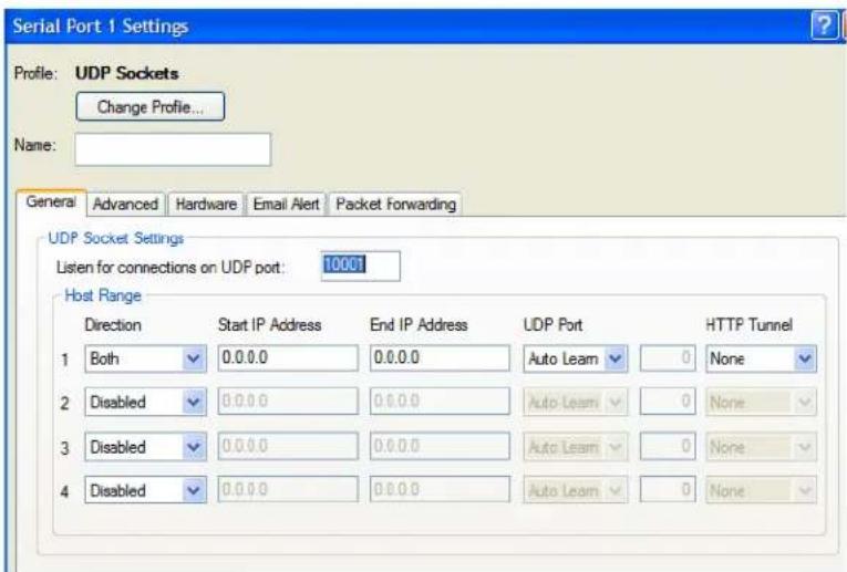
text_image
Serial Port 1 Settings Profile: UDP Sockets Change Profile... Name: General Advanced Hardware Email Alert Packet Forwarding UDP Socket Settings Listen for connections on UDP port: 10001 Host Range Direction Start IP Address End IP Address UDP Port HTTP Tunnel 1 Both 0.0.0.0 0.0.0.0 Auto Learn 0 None 2 Disabled 0.0.0.0 0.0.0.0 Auto Learn 0 None 3 Disabled 0.0.0.0 0.0.0.0 Auto Learn 0 None 4 Disabled 0.0.0.0 0.0.0.0 Auto Learn 0 NoneFour individual entries are provided to allow you greater flexibility to specify how data will be forwarded to/from the serial device. All four entries support the same configuration parameters. You can configure one or more of the entries as needed.
The first thing you need to configure for an entry is the "Direction" of the data flow. The following options are available;
• Disabled - UDP service not enabled.
- LAN to Serial - This setting will allow UDP data to be received from one or more hosts on the LAN and forwarded to the serial device attached to this serial port.
- Serial to LAN - This setting will allow data originating from the serial device attached to this serial port to be sent to one or more hosts on the LAN using UDP datagrams.
- Both - Allows for data to flow from the serial device to the LAN and from the LAN to the serial device.
The role of each of the configurable parameters in an entry depends on the “Direction” selected.
When the direction is "LAN to Serial" the role of the additional parameters is as follow;
- Start IP Address - This is the IP address of the host from which the UDP data will originate. If the data will originate from a number of hosts, this becomes the starting IP address of a range.
- End IP Address - If you wish to receive data only from the single host defined by "Start IP address", leave this entry as is (0.0.0.0). If you wish to accept data from a number of hosts, this address will represent the upper end of a range starting from "Start IP Address". Only data originating from this range will be forwarded to the serial port.
- UDP port - This is the UPD port from which the data will originate. There are three options for this parameter.
●Auto Learn - The first UDP message received will be used to define which UDP port we are going to accept UDP data from. Once learned, only data from this UDP port will be accepted. The data must also originate from a host which is in the IP range defined for this entry. - Any Port - Any UDP port will be accepted as long as the data originates from a host in the IP range defined for this entry.
- Port - Only data originating from the UDP port configured here as well as originating from a host in the IP range defined for this entry will be accepted.
When the direction is "Serial to LAN" the role of the additional parameters is as follow;
- Start IP Address - This is the IP address of the host to which the serial data will be sent using UDP datagrams. If the serial data is to be sent to more than one host, this becomes the starting IP address of a range.
- End IP Address - If you wish to send serial data to a single host, leave this entry as is (0.0.0.0). If you wish to send the serial data to a number of hosts, this address will represent the upper end of a range starting from "Start IP Address".
- UDP port - This is the UPD port to which the serial data will be forwarded. For a direction of "Serial to LAN", you must specify the port to be used.
When the direction is "Both" the role of the additional parameters is as follow;
- Start IP Address - This is the IP address of the host to which the serial data will be sent using UDP datagrams. It is also the IP address of the host from which UDP data coming from the LAN will be accepted from. If the data is to be sent to or received from more than one host, this becomes the starting IP address of a range.
- End IP Address - If you wish to send serial data to a single host and only receive data from the single UDP host, leave this entry as is (0.0.0.0). If the data is to be sent to or received from more than one host, this address will represent the upper end of a range starting from "Start IP Address". Only data originating from this range will be forwarded to the serial port.
- UDP Port - This is the UPD port to which the serial data will be forwarded as well as the UPD port from which data originating on the LAN will be accepted from. For a direction of "Both", there are two valid option for the UDP Port as follows;
●Auto Learn - The first UDP message received will be used to define which port we are going to accept UDP data from. Once learned, only data from this UDP port will be accepted and serial data being forwarded to the LAN will be sent to this UDP port. Until the port is learned, data from the serial port intended to be sent to the LAN will be discarded.
- Port - Serial data being forwarded to the LAN from the serial device will sent to this UDP port. Only data originating from the UDP port configured here (as well as originating from a host in the IP range defined for this entry) will be forwarded to the serial device.
Special values for "Start IP address"
- 0.0.0.0 - This is the "auto learn IP address" value which is valid only in conjunction with the "LAN to Serial" setting. The first UDP packet received for this serial port will set the IP address from which we will accept future UDP packets to be forwarded to the serial port. For this setting, leave the "End IP Address" as 0.0.0.0.
- 255.255.255.255 - This selection is only valid in conjunction with the "LAN to Serial" setting. It will accept all UDP packets received for this serial port regardless of the originating IP address. For this setting, leave the "End IP Address" as 0.0.0.0.
- Subnet directed broadcast - You can use the "Start IP Address" field to enter a subnet directed broadcast address. This is done by specifying the subnet address with the host portion filled with 1s. For example, if you are on the subnet 172.16.x.x with a subnet mask of 255.255.254.0 than you would specify an IP address of 172.16.1.255 (all ones for host portion). For this setting, leave the "End IP Address" as 0.0.0.0. For any "LAN to Serial" ranges you have defined for this serial port, you must ensure that IP address of this IOLAN is not included in the range. If your IP address is within the range, you will receive the data you send via the subnet directed broadcasts as data coming in from the LAN.
An example UDP configuration is described based on the following window.
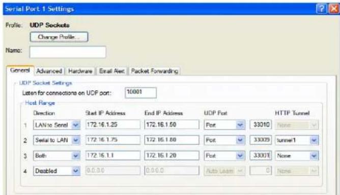
text_image
Serial Port 1 Settings Profile: UDP Sockets Change Profile Name: General Advanced Hardware Email Alert Packet Forwarding UDP Socket Settings Listen for connections on UDP port: 10001 Host Range Direction Start IP Address End IP Address UDP Port HTTP Tunnel 1 LAN to Senel 172.16.1.25 172.16.1.50 Port 33010 None 2 Serial to LAN 172.16.1.75 172.16.1.80 Port 33009 tunnel1 3 Both 172.16.1.1 172.16.1.20 Port 33001 None 4 Disabled 0.0.00 0.0.00 Auto Loan NoneThe UDP configuration window, taken from the DeviceManager, is configured to:
- UDP Entry 1
All UDP data received from hosts that have an IP address that falls within the range of 172.16.1.25 to 172.16.1.50 and source UDP Port of 33010 will be sent to the serial device. The IOLAN will not send any data received on its serial port to the host range defined by this entry.
- UDP Entry 2
All hosts that have an IP Address that falls within the range of 172.16.1.75 to 172.16.1.80 and who listen to UDP Port 33009 will receive UDP data from the serial device. No UDP data originating from the hosts defined by this entry will be forwarded to the serial device.
- UDP Entry 3
All hosts that have an IP address that falls within the range of 172.16.1.1 to 172.16.1.20 and listen to Port 33001 will be sent the data from the serial device in UDP format. The serial device will only receive UDP data from the hosts in that range with a source UDP Port of 33001. The IOLAN will listen for data on the port value configured in the Listen for connections on UDP port parameter. (10001 in above example)
- UDP Entry 4
This entry is disabled since Direction is set to Disabled.
General Tab Field Descriptions
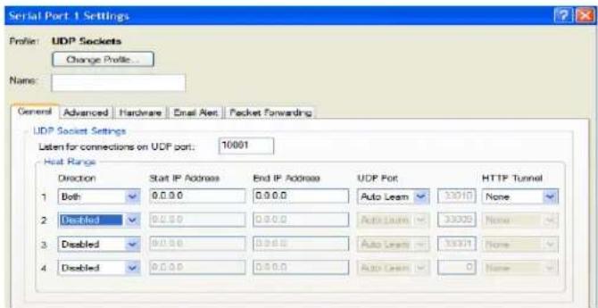
text_image
Serial Port 1 Settings Profile: UDP Sockets Change Profile... Name: General Advanced Hardware Email Alert Packet Forwarding UDP Socket Settings Listen for connections on UDP port: 10001 Hot Range Direction Start IP Address End IP Address UDP Port HTTP Tunnel 1 Both 0.0.0 0.0.0 Auto Learn 33010 None 2 Disabled 0.0.0 0.0.0 Auto Learn 33025 None 3 Disabled 0.0.0 0.0.0 Auto Learn 33071 None 4 Disabled 0.0.0 0.0.0 Auto Learn 0 NoneConfigure the following parameters:
Listen for connections on UDP port The IOLAN will listen for UDP packets on the specified port. Default: 1000+
Direction The direction in which information is received or relayed:
• Disabled—UDP service not enabled.
- LAN to Serial—This setting will allow UDP data to be received from one or more hosts on the LAN and forwarded to the serial device attached to this serial port.
- Serial to LAN—This setting will allow data originating from the serial device attached to this serial port to be sent to one or more hosts on the LAN using UDP datagrams.
- Both—Allows for data to flow from the serial device to the LAN and from the LAN to the serial device.
Default: Both for UDP 1 and Disabled for all other UDP ranges
Start IP Address The first host IP address in the range of IP addresses (for IPv4 or IPv6) that the IOLAN will listen for messages from and/or send messages to.
Field Format: IPv4 or IPv6 address
End IP Address The last host IP address in the range of IP addresses (for IPv4, not supported for IPv6) that the IOLAN will listen for messages from and/or send messages to.
Field Format: IPv4 address
UDP Port
Determines how the IOLAN's UDP port that will send/receive UDP messages is defined:
- Auto Learn—The IOLAN will only listen to the first port that it receives a UDP packet from. Applicable when Direction is set to LAN to Serial or Both.
- Any Port—The IOLAN will receive messages from any port sending UDP packets. Applicable when Direction is set to LAN to Serial.
- Port—The port that the IOLAN will use to relay messages to servers/hosts. This option works with any Direction except Disabled. The IOLAN will listen for UDP packets on the port configured by the Listen for connections on UDP port parameter.
Default: Auto Learn
Port The UDP port to use.
Default: 0 (zero)
HTTP Tunnel Specify the HTTP tunnel to be used for this connection.
Advanced Tab Field Descriptions
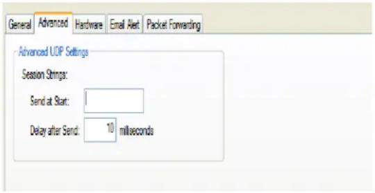
text_image
General Advanced Hardware Email Alert Packet Forwarding Advanced UOP Settings Session Strings: Send at Start: 1 Delay after Send: 10 millisecondsConfigure the following parameters:
Session Strings
Controls the sending of ASCII strings to serial devices at session start as follows;
- Send at Start—If configured, this string will be sent to the serial device on power-up of the IOLAN or when a kill line command is issued on this serial port. If the "monitor DSR" or "monitor DCD" options are set, the string will also be sent when the monitored signal is raised.
Range: 0-127 alpha-numeric characters
Range: hex 0-FF
- Delay after Send—If configured, will inset a delay after the string is sent to the device. This delay can be used to provide the serial device with time to process the string before the session is initiated or terminated.
Default: 10 ms
Terminal Profile
Overview
The Terminal profile allows network access from a terminal connected to the IOLAN's serial port. This profile is used to access pre-defined hosts on the network from the terminal.
Functionality
This profile can be configured for users:
- who must be authenticated by the IOLAN first and then a connection to a host can be established.
• who are connecting through the serial port directly to a host.
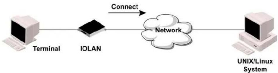
flowchart
graph LR
    A["Terminal"] -->|Connect| B["IOLAN"]
    B --> C["Network"]
    C --> D["UNIX/Linux System"]
General Tab Field Descriptions
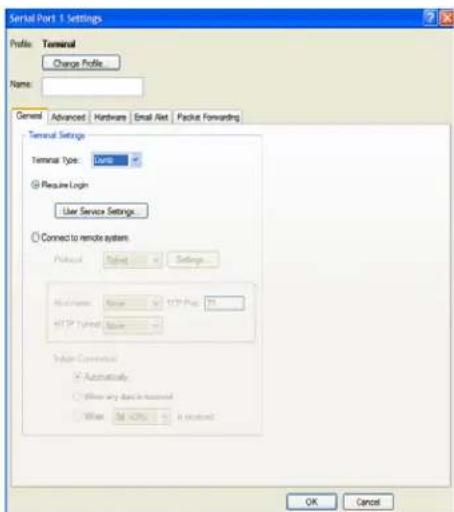
text_image
Serial Port 1 Settings Profile: Terminal Change Profile Name: General Advanced Hardware Email Alert Packus Forwarding Terminal Settings Terminal Type: Type Require Login User Service Settings Connect to remote system Protocol Name Settings Maximum Name TCP Port 75 HTTP Options Name Option Connection Automatically Allow any data to terminal Allow TCP port is installed OK CancelConfigure the following parameters:
Terminal Type Specifies the type of terminal connected to the line.
Data Options:
Dumb
WYSE60
VT100
• ANSI
TVI925
IBM3151TE
• VT320 (specifically supporting VT320-7)
• HP700 (specifically supporting HP700/44)
• Term1, Term2, Term3 (user-defined terminals)
Default: Dumb
Require Login When users access the IOLAN through the serial port, they must be authenticated, using either the local user database or an external authentication server.
Default: Enabled
User Service Settings Button After a user has been successfully authenticated, the IOLAN will connect to the specified host using the specified protocol according to:
• the User Service parameter for locally configured users
- the Default User Service parameter for users who are externally authenticated
- TACACS+/RADIUS for externally authenticated users where the target host is passed to the IOLAN
See User Service Settings for field descriptions of the various User Service Settings.
Connect to Remote System When the serial port is started, the IOLAN will initiate a connection to the specified host using the specified protocol. With this option, user authentication will not be performed by the IOLAN.
Default: Disabled
Protocol Specify the protocol that will be used to connect to the specified host.
Data Options: Telnet, SSH, Rlogin
Default: Telnet
Settings Button Click this button to define the settings for the protocol that will be used to connect the user to the specified host.
Host Name The name (resolvable via DNS) or IP address of the configured host the IOLAN will connect to.
TCP Port The TCP Port that the IOLAN will use to connect to the host.
Default: Telnet-23, SSH-22, Rlogin-513
Automatically If the serial port hardware parameters have been setup to monitor DSR or DCD, the host session will be started once the signals are detected. If no hardware signals are being monitored, the IOLAN will initiate the session immediately after being powered up.
Default: Enabled
When any data is received Initiates a connection to the specified host when any data is received on the serial port.
Default: Disabled
When <hexadecimal Initiates a connection to the specified host only when the specified character is received on the serial port.
value> is received Default: Disabled
Advanced Tab Field Descriptions
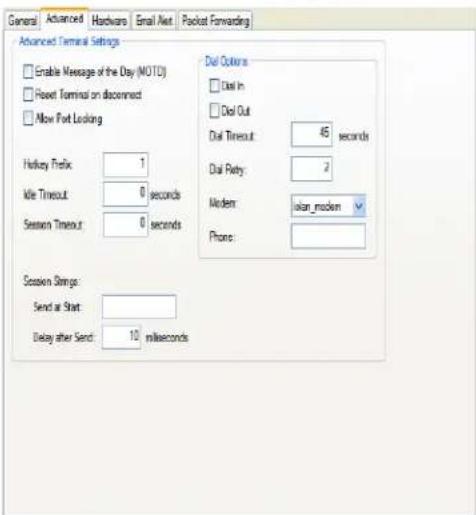
text_image
General Advanced Hardware Email Alert Pocket Forwarding Advanced Terminal Settings Enable Message of the Day (MOTC) Reset Terminal on disconnect Allow Port Looking Hockey Prefix: 1 Mid Timeout: 0 seconds Session Timeout: 0 seconds Session Strings: Send at Start: Delay after Send: 10 milliseconds Dial Colors Dial In Dial Out Dial Timeout: 45 seconds Dial Retry: 2 Modern: islan_modem Phone:Configure the following parameters:
Enable Message of Enables/disables the display of the message of the day.
the Day (MOTD) Default: Disabled
Reset Terminal on disconnect When enabled, resets the terminal definition connected to the serial port when a user logs out.
Default: Disabled
Allow Port Locking When enabled, the user can lock his terminal with a password using the Hotkey Prefix (default Ctrl-a) ^a I (lowercase L). The IOLAN prompts the user for a password and a confirmation.
Default: Disabled
Hotkey Prefix
The prefix that a user types to lock a serial port or redraw the Menu.
Data Range:
- ^a I—(Lowercase L) Locks the serial port until the user unlocks it. The user is prompted for a password (any password, excluding spaces) and locks the serial port. Next, the user must retype the password to unlock the serial port.
- ^r—When you switch from a session back to the Menu, the screen may not be redrawn correctly. If this happens, use this command to redraw it properly. This is always Ctrl R, regardless of the Hotkey Prefix.
You can use the Hotkey Prefix key to lock a serial port only when the Allow Port Locking parameter is enabled.
Default: hexadecimal 01 (Ctrl-a, ^a)
Idle Timeout
Use this timer to close a connection because of inactivity. When the Idle Timeout expires, the IOLAN will end the connection.
Range: 0-4294967 seconds (about 49 days)
Default: 0 seconds so the port will never timeout
Session Timeout
Use this timer to forcibly close the session/connection when the Session Timeout expires.
Default: 0 seconds so the port will never timeout
Range: 0-4294967 seconds (about 49 days)
Session Strings
Controls the sending of ASCII strings to serial device at session start as follows;
- Send at Start—If configured, this string will be sent to the serial device on power-up of the IOLAN, or when a kill line command is issued on this serial port. If the "monitor DSR" or "monitor DCD" options are set, the string will also be sent when the monitored signal is raised.
Range: 0-127 alpha-numeric characters
Range: hexadecimal 0-FF
- Delay after Send - If configured, will inset a delay after the string is sent to the device. This delay can be used to provide the serial device with time to process the string before the session is initiated.
Default: 10 ms
Dial Timeout
The number of seconds the IOLAN will wait to establish a connection to a remote modem.
Range: 1-99
Default: 45 seconds
Dial Retry
The number of times the IOLAN will attempt to re-establish a connection with a remote modem.
Range: 0-99
Default: 2
Dial In If the device is remote and will be dialing in via modem or ISDN TA, enable this parameter.
Default: Disabled
Dial Out
If you want the modem to dial a number when the serial port is started, enable this parameter.
Default: Disabled
User Service Settings
Login Settings
These settings apply to users who are accessing the network from a terminal connected to the IOLAN's serial port. The Telnet, Rlogin, SSH, SLIP, PPP settings take effect when the connection method is defined in the user's profile (or are passed to the IOLAN by a RADIUS or TACACS+ server when those authentication methods are being used).
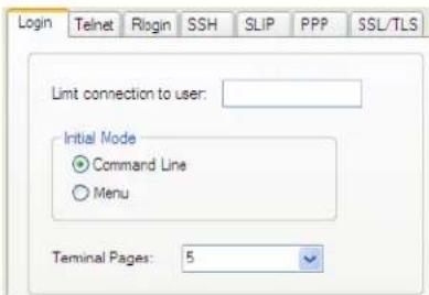
text_image
Login Telnet Rlogin SSH SLIP PPP SSL/TLS Limit connection to user: Initial Mode ● Command Line ○ Menu Terminal Pages: 5Configure the following parameters:
Limit Connection to User Makes the serial port dedicated to the specified user. The user won't need to enter their login name - just their password.
Initial Mode Specifies the initial interface a user navigates when logging into the serial port. Data Options: Menu, Command Line Default: Command Line
Terminal Pages The number of video pages the terminal supports. Range: 1-7 Default: 5 pages
Telnet Settings
The Telnet settings apply when the User Service is set to Telnet or the Terminal profile specifies a Telnet connection to a host.
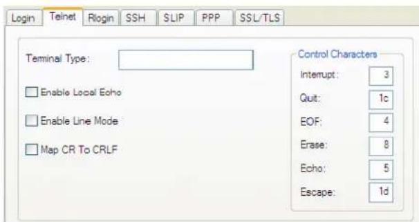
text_image
Login Telnet Rlogin SSH SLIP PPP SSL/TLS Terminal Type: Enable Local Echo Enable Line Mode Map CR To CRLF Control Characters Interrupt: 3 Quit: 1c EOF: 4 Erase: 8 Echo: 5 Escape: 1dConfigure the following parameters:
Terminal Type Type of terminal attached to this serial port; for example, ANSI or WYSE60.
| Enable Local Echo | Toggles between local echo of entered characters and suppressing local echo. Local echo is used for normal processing, while suppressing the echo is convenient for entering text that should not be displayed on the screen, such as passwords. This parameter can be used only when Enable Line Mode is enabled.Default: Disabled |
| Enable Line Mode | When enabled, keyboard input is not sent to the remote host until Enter is pressed, otherwise input is sent every time a key is pressed.Default: Disabled |
| Map CR to CRLF | When enabled, maps carriage returns (CR) to carriage return line feed (CRLF).Default: Disabled |
| Interrupt | Defines the interrupt character. Typing the interrupt character interrupts the current process. This value is in hexadecimal.Default: 3 (ASCII value ^C) |
| Quit | Defines the quit character. Typing the quit character closes and exits the current telnet session. This value is in hexadecimal.Default: 1c (ASCII value FS) |
| EOF | Defines the end-of-file character. When Enable Line Mode is enabled, entering the EOF character as the first character on a line sends the character to the remote host. This value is in hexadecimal.Default: 4 (ASCII value ^D) |
| Erase | Defines the erase character. When Line Mode is Off, typing the erase character erases one character. This value is in hexadecimal.Default: 8 (ASCII value ^H) |
| Echo | Defines the echo character. When Line Mode is On, typing the echo character echoes the text locally and sends only completed lines to the host. This value is in hexadecimal.Default: 5 (ASCII value ^E) |
| Escape | Defines the escape character. Returns you to the command line mode. This value is in hexadecimal.Default: 1d (ASCII value GS) |
Rlogin Settings
The Rlogin settings apply when the User Service is set to Rlogin or the Terminal profile has Require Login selected and specifies an Rlogin connection to a host.
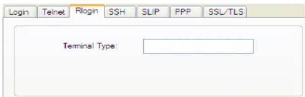
text_image
Login Telnet Rlogin SSH SLIP PPP SSL/TLS Terminal Type:Configure the following parameter:
Terminal Type
Type of terminal attached to this serial port; for example, ANSI or WYSE60.
When Connect to remote system is selected, the Rlogin window requires the name of the user who is connecting to the host.
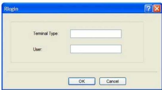
text_image
Rlogin Terminal Type: User: OK CancelConfigure the following parameters:
Terminal Type Type of terminal attached to this serial port; for example, ANSI or WYSE60.
User This name is passed on to the specified host for the Rlogin session, so that the user is only prompted for a password.
SSH Settings
The SSH settings apply when the User Service is set to SSH or the Terminal profile specifies an SSH connection to a host.
Some combinations of cipher groups are not available on FIPS firmware versions. SSH-1 protocol is not available on FIPS firmware versions.
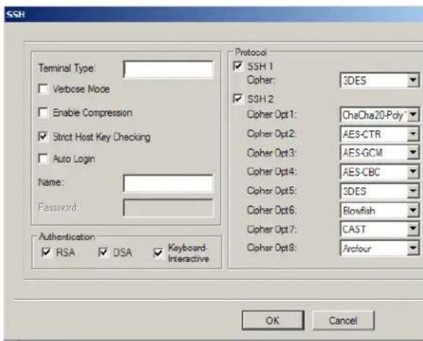
text_image
SSH Terminal Type: Verbose Mode Enable Compression Strict Host Key Checking Auto Login Name: Password: Authentication RSA DSA Keyboard-Interactive Protocol SSH 1 Cipher: 3DES SSH 2 Cipher Opt1: CheCha20-Poly Cipher Opt2: AES-CTR Cipher Opt3: AES-GCM Cipher Opt4: AES-CBC Cipher Opt5: 3DES Cipher Opt6: Blowfish Cipher Opt7: CAST Cipher Opt8: Arcfour OK CancelConfigure the following parameters:
Terminal Type Type of terminal attached to this serial port; for example, ANSI or WYSE60.
Verbose Mode When enabled, displays debug messages on the terminal.
Default: Disabled
Enable Compression When enabled, requests compression of all data. Compression is desirable on modem lines and other slow connections, but will only slow down things on fast networks.
Default: Disabled
Strict Host Key Checking When enabled, a host public key (for each host you wish to ssh to) must be downloaded into the IOLAN.
Default: Enabled
Auto Login When enabled, creates an automatic SSH login, using the Name and Password values.
Default: Disabled
Name The name of the user logging into the SSH session.
Field Format: Up to 20 alphanumeric characters, excluding spaces
Password The user's password when Auto Login is enabled.
Field Format: Up to 20 alphanumeric characters, excluding spaces
SSH1 When enabled, selects an SSH version 1 connection.
Default: Enabled
SSH1 Cipher Select the encryption method (cipher) that you want to use for your SSH version 1 connection:
Data Options:
3DES
- Blowfish
Default: 3DES
SSH2 When enabled, selects an SSH version 2 connection. If both SSH 1 and SSH 2 are selected, the IOLAN will attempt to make an SSH 2 connection first. If that connection fails, it will attempt to connect to the specified host using SSH 1.
Default: Enabled
SSH2 Ciphers Select the order of negotiation for the encryption method (ciphers) that the Opt1-8 IOLAN will use for the SSH version 2 connection:
Data Options:
- ChaCha20-Poly1305
AES-CTR
AES-GCM
AES-CBC
3DES
- Blowfish
CAST
Arcfour
RSA When enabled, an authentication method used by SSH version 1 and 2. Use RSA authentication for the SSH session.
Default: Enabled
DSA When enabled, an authentication method used by SSH version 2. Use DSA authentication for the SSH session.
Default: Enabled
Keyboard When enabled, the user types in a password for authentication.
Authentication Default: Enabled
SLIP Settings
The SLIP settings apply when the User Service is set to SLIP.

text_image
Login Telnet Rlogin SSH SLIP PPP SSL/TLS Local IP Address: 0 . 0 . 0 . 0 Remote IP Address: 0 . 0 . 0 . 0 Subnet Mask: 0 . 0 . 0 . 0 MTU: 256 Routing: None VJ CompressionConfigure the following parameters:
Local IP Address
The IPv4 address of the IOLAN end of the SLIP link. For routing to work you must enter an IP address in this field. Choose an address that is part of the same network or subnetwork as the remote end; for example, if the remote end is address 192.101.34.146, your local IP address can be 192.101.34.145. Do not use the IOLAN's (main) IP address in this field; if you do so, routing will not take place correctly.
Remote IP Address
The IPv4 address of the remote end of the SLIP link. Choose an address that is part of the same network or subnetwork as the IOLAN. If your user is authenticated by the IOLAN, this remote IP address will be overridden if you have set a Framed IP Address for the user. If your user is authenticated by RADIUS and the RADIUS parameter Framed-Address is set in the RADIUS file, the IOLAN will use the value in the RADIUS file in preference to the value configured here.
Subnet Mask The network subnet mask. For example, 255.255.0.0. If your user is authenticated by RADIUS and the RADIUS parameter Framed-Netmask is set in the RADIUS file, the IOLAN will use the value in the RADIUS file in preference to the value configured here.
MTU The Maximum Transmission Unit (MTU) parameter restricts the size of individual SLIP packets being sent by the IOLAN. Enter a value between 256 and 1006 bytes; for example, 512. The default value is 256. If your user is authenticated by the IOLAN, this MTU value will be overridden when you have set a Framed MTU value for the user. If your user is authenticated by RADIUS and the RADIUS parameter Framed-MTU is set in the RADIUS file, the IOLAN will use the value in the RADIUS file in preference to the value configured here.
Default: 256
Routing Determines the routing mode (RIP, Routing Information Protocol) used on the SLIP interface as one of the following options:
• None—Disables RIP over the SLIP interface.
- Send—Sends RIP over the SLIP interface.
- Listen—Listens for RIP over the SLIP interface.
- Send and Listen—Sends RIP and listens for RIP over the SLIP interface.
This is the same function as the Framed-Routing attribute for RADIUS authenticated users.
Default: None
VJ Compression
When enabled, Van Jacobson compression is used on this link. When enabled, C-SLIP, or compressed SLIP, is used. When disabled, plain SLIP is used. C-SLIP greatly improves the performance of interactive traffic, such as Telnet or Rlogin.
If your user is authenticated by the IOLAN, this VJ compression value will be overridden if you have set a Framed Compression value for a user. If your user is authenticated by RADIUS and the RADIUS parameter Framed-Compression is set in the RADIUS file, the IOLAN will use the value in the RADIUS file in preference to the value configured here.
Default: Enabled
PPP Settings
The PPP settings apply when the User Service is set to PPP.
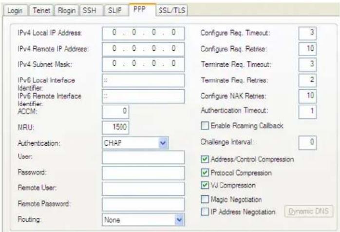
text_image
Login Teinet Rlogin SSH SLIP PPP SSL/TLS IPv4 Local IP Address: 0 . 0 . 0 . 0 IPv4 Remote IP Address: 0 . 0 . 0 . 0 IPv4 Subnet Mask: 0 . 0 . 0 . 0 IPv6 Local Interface Identifier: : : IPv6 Remote Interface Identifier: : : ACCM: 0 MRU: 1500 Authentication: CHAP User: Password: Remote User: Remote Password: Routing: None Configure Req. Timeout: 3 Configure Req. Retries: 10 Terminate Req. Timeout: 3 Terminate Req. Retries: 2 Configure NAK Retries: 10 Authentication Timeout: 1 Enable Roaming Callback Challenge Interval: 0 Address/Control Compression Protocol Compression VJ Compression Magic Negotiation IP Address Negotiation Dynamic DNSConfigure the following parameters:
IPv4 Local IP Address
The IPV4 IP address of the IOLAN end of the PPP link. For routing to work, you must enter a local IP address. Choose an address that is part of the same network or subnetwork as the remote end; for example, if the remote end is address 192.101.34.146, your local IP address can be 192.101.34.145. Do not use the IOLAN's (main) IP address in this field; if you do so, routing will not take place correctly.
IPv4 Remote IP Address
The IPV4 IP address of the remote end of the PPP link. Choose an address that is part of the same network or subnetwork as the IOLAN. If you set the PPP parameter IP Address Negotiation to On, the IOLAN will ignore the remote IP address value you enter here and will allow the remote end to specify its IP address. If your user is authenticated by RADIUS and the RADIUS parameter Framed-Address is set in the RADIUS file, the IOLAN will use the value in the RADIUS file in preference to the value configured here. The exception to this rule is a Framed-Address value in the RADIUS file of 255.255.255.254; this value allows the IOLAN to use the remote IP address value configured here.
IPv4 Subnet Mask The network subnet mask. For example, 255.255.0.0. If your user is authenticated by RADIUS and the RADIUS parameter Framed-Netmask is set in the RADIUS file, the IOLAN will use the value in the RADIUS file in preference to the value configured here.
IPv6 Local Interface Identifier
The local IPv6 interface identifier of the IOLAN end of the PPP link. For routing to work, you must enter a local IP address. Choose an address that is part of the same network or subnetwork as the remote end. Do not use the IOLAN's (main) IP address in this field; if you do so, routing will not take place correctly.
Field Format: The first 64 bits of the Interface Identifier must be zero, therefore, ::abcd:abcd:abcd:abcd is the expected format.
IPv6 Remote Interface Identifier
The remote IPv6 interface identifier of the remote end of the PPP link. Choose an address that is part of the same network or subnetwork as the IOLAN. If you enable Negotiate IP Address Automatically, the IOLAN will ignore the remote IP address value you enter here and will allow the remote end to specify its IP address. If your user is authenticated by RADIUS and the RADIUS parameter Framed-Interface-ID is set in the RADIUS file, the IOLAN will use the value in the RADIUS file in preference to the value configured here.
Field Format: The first 64 bits of the Interface Identifier must be zero, therefore, ::abcd:abcd:abcd:abcd is the expected format.
ACCM
Specifies the ACCM (Asynchronous Control Character Map) characters that should be escaped from the data stream.
Field Format: This is entered as a 32-bit hexadecimal number with each bit specifying whether or not the corresponding character should be escaped. The bits are specified as the most significant bit first and are numbered 31-0. Thus if bit 17 is set, the 17th character should be escaped, that is, 0x11 (XON). The value 000a0000 will cause the control characters 0x11 (XON) and 0x13 (XOFF) to be escaped on the link, thus allowing the use of XON/XOFF (software) flow control. If you have selected Soft Flow Control on the Serial Port, you must enter a value of at least 000a0000 for the ACCM.
Default: 00000000, which means no characters will be escaped
MRU
The Maximum Receive Unit (MRU) parameter specifies the maximum size of PPP packets that the IOLAN's port will accept. If your user is authenticated by the IOLAN, the MRU value will be overridden if you have set a MTU value for the user. If your user is authenticated by RADIUS and the RADIUS parameter Framed-MTU is set in the RADIUS file, the IOLAN will use the value in the RADIUS file in preference to the value configured here.
Range: 64-1500 bytes
Default: 1500
Authentication
The type of authentication that will be done on the link. You can use PAP or CHAP (MD5-CHAP, MS-CHAPv1 and MS-CHAPv2) to authenticate a user or client on the IOLAN. When setting either PAP and CHAP, make sure the IOLAN and the PPP peer, have the same setting. For example, if the IOLAN is set to PAP, but the remote end is set to CHAP, the connection will be refused.
Data Options:
None - no authentication will be performed.
PAP—is a one time challenge of a client/device requiring that it respond with a valid username and password. A timer operates during which successful authentication must take place. If the timer expires before the remote end has been authenticated successfully, the link will be terminated.
CHAP—challenges a client/device at regular intervals to validate itself with a username and a response, based on a hash of the secret (password). A timer operates during which successful authentication must take place. If the timer expires before the remote end has been authenticated successfully, the link will be terminated. MD5-CHAP and Microsoft MS-CHAPv1/MS-CHAPv2 are supported. The IOLAN will attempt MS-CHAPv2 with MPPC compression, but will negotiate to the variation of CHAP, compression and encryption that the remote peer wants to use.
Default: CHAP
User
Complete this field only if you have specified PAP or CHAP (security protocols) in the Authentication field, and
- you wish to dedicate this line to a single remote user, who will be authenticated by the IOLAN, or
- you are using the IOLAN as a router (back-to-back with another IOLAN).
When Connect is set to Dial Out or both Dial In/Dial Out are enabled, the User is the name the remote device will use to authenticate a port on this IOLAN.
The remote device will only authenticate your IOLAN's port when PAP or CHAP are operating. You can enter a maximum of sixteen alphanumeric characters; for example, tracy201. When connecting together two networks, enter a dummy user name; for example, DS_HQ.
Note If you want a reasonable level of security, the user name and password should not be similar to a user name or password used regularly to login to the IOLAN. External authentication can not be used for this user.
Field Format: You can enter a maximum of 254 alphanumeric characters.
Password
Complete this field only if you have specified PAP or CHAP (security protocols) in the Security field and:
- you wish to dedicate this serial port to a single remote user, who will be authenticated by the IOLAN, or
- you are using the IOLAN as a router (back-to-back with another IOLAN) Password means the following:
- When PAP is specified, this is the password the remote device will use to authenticate the port on this IOLAN.
- When CHAP is specified, this is the secret (password) known to both ends of the link upon which responses to challenges shall be based.
Field Format: You can enter a maximum of 16 alphanumeric characters.
Remote User
Complete this field only if you have specified PAP or CHAP (security protocols) in the Security field, and
- you wish to dedicate this line to a single remote user, who will be authenticated by the IOLAN, or
- you are using the IOLAN as a router (back-to-back with another IOLAN)
When Dial In or Dial In/Dial Out is enabled, the Remote User is the name the IOLAN will use to authenticate the port on the remote device. Your IOLAN will only authenticate the port on the remote device when PAP or CHAP are operating. When connecting together two networks, enter a dummy user name; for example, DS_SALES.
Note If you want a reasonable level of security, the user name and password should not be similar to a user name or password used regularly to login to the IOLAN. This option does not work with external authentication.
Field Format: You can enter a maximum of 254 alphanumeric characters.
Remote Password
Complete this field only if you have specified PAP or CHAP (security protocols) in the Security field, and
- you wish to dedicate this serial port to a single remote user, and this user will be authenticated by the IOLAN, or
- you are using the IOLAN as a router (back-to-back with another IOLAN) Remote password means the following:
- When PAP is specified, this is the password the IOLAN will use to authenticate the remote device.
- When CHAP is specified, this is the secret (password) known to both ends of the link upon which responses to challenges will be based.
Remote Password is the opposite of the parameter Password. Your IOLAN will only authenticate the remote device when PAP or CHAP is operating.
Field Format: You can enter a maximum of 16 alphanumeric characters.
Routing Determines
the routing mode (RIP, Routing Information Protocol) used on the PPP interface. This is the same function as the Framed-Routing attribute for RADIUS authenticated users.
Data Options
• None—Disables RIP over the PPP interface.
- Send—Sends RIP over the PPP interface.
- Listen—Listens for RIP over the PPP interface.
- Send and Listen—Sends RIP and listens for RIP over the PPP interface.
Default: None
Configure Req. Timeout
The maximum time, in seconds, that LCP (Link Control Protocol) will wait before it considers a configure request packet to have been lost.
Range: 1-255
Default: 3 seconds
Configure Req. Retries
The maximum number of times a configure request packet will be re-sent before the link is terminated.
Range: 0-255
Default: 10 seconds
| Terminate Req. Timeout | The maximum time, in seconds, that LCP (Link Control Protocol) will wait before it considers a terminate request packet to have been lost.Range: 1-255Default: 3 seconds |
| Terminate Req. Retries | The maximum number of times a terminate request packet will be re-sent before the link is terminated.Range: 0-255Default: 2 seconds |
| Configure NAK Retries | The maximum number of times a configure NAK packet will be re-sent before the link is terminated.Range: 0-255Default: 10 seconds |
| Authentication Timeout | The timeout, in minutes, during which successful PAP or CHAP authentication must take place (when PAP or CHAP are specified). If the timer expires before the remote end has been authenticated successfully, the link will be terminated.Range: 1-255Default: 1 minute |
| Roaming Callback | A user can enter a telephone number that the IOLAN will use to callback him/her. This feature is particularly useful for a mobile user. Roaming callback can only work when the User Enable Callback parameter is enabled. Enable Roaming Callback therefore overrides (fixed) User Enable Callback. To use Enable Roaming Callback, the remote end must be a Microsoft Windows OS that supports Microsoft's Callback Control Protocol (CBCP). The user is allowed 30 seconds to enter a telephone number after which the IOLAN ends the call.Default: Disabled |
| Challenge Interval | The interval, in minutes, for which the IOLAN will issue a CHAP re-challenge to the remote end. During CHAP authentication, an initial CHAP challenge takes place, and is unrelated to CHAP re-challenges. The initial challenge takes place even if re-challenges are disabled. Some PPP client software does not work with CHAP re-challenges, so you might want to leave the parameter disabled in the IOLAN.Range: 0-255Default: 0 (zero), meaning CHAP re-challenge is disabled |
| Address/Control Compression | This determines whether compression of the PPP Address and Control fields take place on the link. For most applications this should be enabled.Default: Enabled |
| Protocol Compression | This determines whether compression of the PPP Protocol field takes place on this link.Default: Enabled |
| VJ Compression | When enabled, Van Jacobson Compression is used on this link. If your user is authenticated by the IOLAN, this VJ compression value will be overridden if you have enabled the User, Enable VJ Compression parameter. If the user is authenticated by RADIUS and the RADIUS parameter Framed-Compression is set in the RADIUS file, the IOLAN will use the value in the RADIUS file in preference to the value configured here.Default: Enabled |
| Magic Negotiation | Determines if a line is looping back. If enabled (On), random numbers are sent on the link. The random numbers should be different, unless the link loops back.Default: Disabled |
| IP Address Negotiation | Specifies whether or not IP address negotiation will take place. IP address negotiation is where the IOLAN allows the remote end to specify its IP address. When On, the IP address specified by the remote end will be used in preference to the Remote IP Address set for a Serial Port. When Off, the Remote IP Address set for the Serial Port will be used.Default: Disabled |
| Dynamic DNS Button | Launches the Dynamic DNS window when IP Address Negotiation is enabled, which can then update the DNS server with the IP address that is negotiated and accepted for the PPP session. |
Printer Profile
Overview
The Printer profile allows for the serial port to be configured to support a serial printer device that can be access by the network.
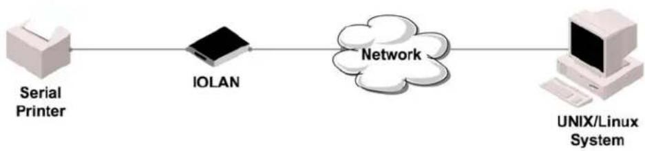
flowchart
graph LR
    A["Serial Printer"] --> B["IOLAN"]
    B --> C["Network"]
    C --> D["UNIX/Linux System"]
General Tab Field Descriptions
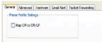
text_image
General Advanced Hardware Email Alert Packet Forwarding Printer Profile Settings □ Map CR to CR/LFConfigure the following parameter:
Map CR to CR/LF Defines the default end-of-line terminator as CR/LF (ASCII carriage-return line-feed) when enabled.
Default: Disabled
Advanced Tab Field Descriptions
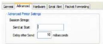
text_image
General Advanced Hardware Email Not Packet Forwarding Advanced Printer Settings Season Strings: Send at Start: 1 Delay after Send: 10 millisecondsConfigure the following parameter:
Session Strings
Controls the sending of ASCII strings to serial device at session start as follows;
- Send at Start—If configured, this string will be sent to the serial device on power-up of the IOLAN, or when a kill line command is issued on this serial port. If the "monitor DSR" or "monitor DCD" options are set, the string will also be sent when the monitored signal is raised.
Range: 0-127 alpha-numeric characters
Range: hexadecimal 0-FF
- Delay after Send - If configured, will inset a delay after the string is sent to the device. This delay can be used to provide the serial device with time to process the string before the session is initiated.
Default: 10 ms
Serial Tunneling Profile
Overview
The Serial Tunneling profile allows two IOLANs to be connected back-to-back over the network to establish a virtual link between two serial ports based on RFC 2217.
Functionality
The serial device that initiates the connection is the Tunnel Client and the destination is the Tunnel Server, although once the serial communication tunnel has been successfully established, communication can go both ways.

flowchart
graph LR
    A["Serial Device"] --> B["IOLAN"]
    B --> C["Network"]
    C --> D["IOLAN"]
    D --> E["Serial Device"]
A more detailed implementation of the Serial Tunneling profile is as follows:

flowchart
graph LR
    A["Server"] -->|Serial| B["IOLAN"]
    B --> C["Network"]
    C --> D["IOLAN"]
    D --> E["Serial Client Tunnel"]
    E --> F["Server"]
The Server Tunnel will also support Telnet Com Port Control protocol as detailed in RFC 2217.
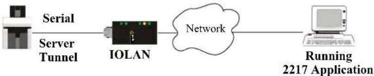
flowchart
graph LR
    A["Server Tunnel"] --> B["IOLAN"]
    B --> C["Network"]
    C --> D["Running 2217 Application"]
The IOLAN serial port signals will also follow the signals on the other serial port. If one serial port receives DSR then it will raise DTR on the other serial port. If one serial port receives CTS then it will raise RTS on the other serial port. The CD signal is ignored.
General Tab Field Descriptions
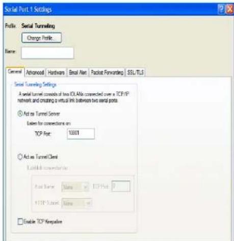
text_image
Serial Port 1 Settings Profile: Serial Tunneling Change Profile. Name: General Advanced Hardware Email Alert Packout Forwarding SSL/TLS Serial Tunneling Settings A serial tunnel consists of two IOLANs connected over a TCP/IP network and creating a virtual link between two serial ports. Act as Tunnel Server Letters for connections on TCP Port: 10001 Act as Tunnel Client Network Connection to Host Name Name TCP Port 0 TCP Port Name Enable TCPKeppakeConfigure the following parameters:
| Act As Tunnel Server | The IOLAN will listen for an incoming connection request on the specified Internet Address on the specified TCP Port.Default: Enabled |
| TCP Port | The TCP port that the IOLAN will listen for incoming connection on.Default: 10000+serial port number; so serial port 5 is 10005. |
| Act as Tunnel Client | The IOLAN will initiate the connection the Tunnel Server.Default: Disabled |
| Host Name | A preconfigured host name that is associated with the IP address of the Tunnel Server. |
| TCP Port | The TCP port that the IOLAN will use to connect to the Tunnel Server.Default: 10000+serial port number; so serial port 5 is 10005. |
| HTTP Tunnel | Specify the HTTP tunnel to be used for this connection. |
| Enable TCP Keepalive | Enables a per-connection TCP keepalive feature. After the configured number of seconds, the connection will send a gratuitous ACK to the network peer, thus either ensuring the connection stays active OR causing a dropped connection condition to be recognized.This parameter needs to be used in conjunction with Monitor Connection Status Interval parameter found in the Serial, Advanced, Advanced Settings tab. The interval specifies the inactivity period before "testing" the connection.Default: Disabled |
Advanced Tab Field Descriptions
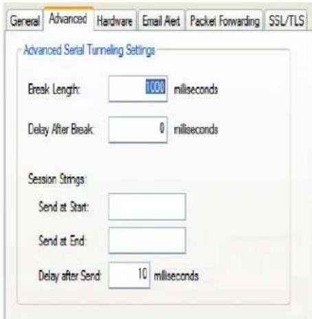
text_image
General Advanced Hardware Email Alert Packet Forwarding SSL/TLS Advanced Serial Tunneling Settings Break Length: 1000 milliseconds Delay After Break: 0 milliseconds Session Strings: Send at Start: Send at End: Delay after Send: 10 millisecondsConfigure the following parameters:
Break Length
When the IOLAN receives a command from its peer to issue a break signal, this parameters defines the length of time the break condition will be asserted on the serial port
Default: 1000ms (1 second)
Delay After Break
This parameter defines the delay between the termination of a break condition and the time data will be sent out the serial port.
Default: 0ms (no delay).
Session Strings
Controls the sending of ASCII strings to serial devices at session start and session termination as follows;
- Send at Start—If configured, this string will be sent to the serial device on power-up of the IOLAN or when a kill line command is issued on this serial port. If the "monitor DSR" or "monitor DCD" options are set, the string will also be sent when the monitored signal is raised.
Range: 0-127 alpha-numeric characters
Range: hexadecimal 0-FF
- Send at End—If configured, this string will be sent to the serial device when the TCP session on the LAN is terminated. If multihost is configured, this string will only be send in listen mode to the serial device when all multihost connections are terminated.
• Range: 0-127 alpha-numeric characters
Range: hexadecimal 0-FF
- Delay after Send—If configured, will inset a delay after the string is sent to the device. This delay can be used to provide the serial device with time to process the string before the session is initiated or terminated.
Default: 10 ms
Virtual Modem Profile
Overview
Virtual Modem (Vmodem) is a feature of the IOLAN that provides a modem interface to a serial device. It will respond to AT commands and provide signals in the same way that a serially attached modem would. This feature is typically used when you are replacing dial-up modems with the IOLAN in order to provide Ethernet network connectivity.
Functionality
The serial port will behave in exactly the same fashion as it would if it were connected to a modem. Using AT commands, it can configure the modem and the issue a dial-out request (ATTD). The IOLAN will then translate the dial request into a TCP connection and data will be begin to flow in both directions. The connection can be terminated by “hanging” up the phone line.
You can also manually start a connection by typing ATD
ATD12303402304310001, without any punctuation (although you do need to add zeros where there are not three digits presents, so that the IP address is 12 digits long).
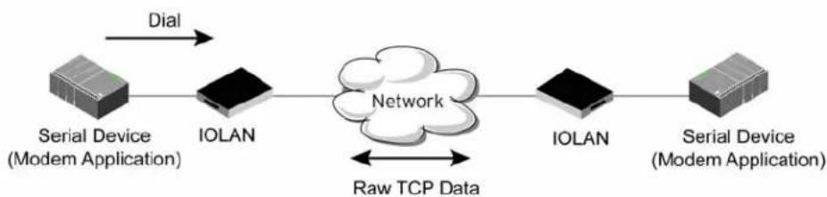
flowchart
graph LR
    A["Serial Device (Modem Application)"] -->|Dial| B["IOLAN"]
    B --> C["Network"]
    C -->|Raw TCP Data| D["IOLAN"]
    D --> E["Serial Device (Modem Application)"]
General Tab Field Descriptions
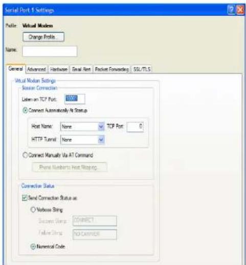
text_image
Serial Port 1 Settings Profile: Virtual Modem Change Profile Name: General Advanced Hardware Email Rent Packet Forwarding SSL/TLS Virtual Motion Settings Session Connection Listen on TCP Port: 1000 Connect Automatically At Setup Host Name: None TCP Port: 0 HTTP Tunnel: None Connect Manually Via AT Command Panel Numbers Host Mapping Connection Status Send Connection Status as: Verbose Sting Success Sting CONNECT False Sting NO CARRIER Numerical CodeConfigure the following parameters:
Listen on TCP Port The IOLAN TCP port that the IOLAN will listen on.
Default: 10000 + serial port number (for example, serial port 12 defaults to 10012)
Connect When enabled, automatically establishes the virtual modem connection when Automatically At the serial port becomes active.
Startup Default: Enabled
Host Name The preconfigured target host name.
TCP Port The port number the target host is listening on for messages.
Default: 0 (zero)
HTTP Tunnel Specify the HTTP tunnel to be used for this connection.
Connect Manually Via AT Command When enabled, the virtual modem requires an AT command before it establishes a connection. Specify this option when your modem application sends a phone number or other AT command to a modem. The serial device can supply an IP address directly or it can provide a phone number that will be translated into an IP address by the IOLAN using the mapping table.
Default: Disabled
Phone Number to Host Mapping When your modem application provides a phone number in an AT command string, you can map that phone number to the destination host.
Button See Phone Number to Host Mapping for information about the window that appears when you click this button.
Send Connection Status As When enabled, the connection success/failure indication strings are sent to the connected device, otherwise these indications are suppressed. This option also determines the format of the connection status results that are generated by the virtual modem.
Default: Enabled
Verbose String When enabled, the connection status is sent by text strings to the connected device.
Default: Disabled
Success String String that is sent to the serial device when a connection succeeds.
Default: CONNECT
Failure String String that is sent to the serial device when a connection fails.
Default: NO CARRIER
Numeric Codes When enabled, the connection status is sent to the connected device using the following numeric codes:
• 0 OK
• 1 CONNECTED
2 RING
• 3 NO CARRIER
4 ERROR
- 6 INTERFACE DOWN
• 7 CONNECTION REFUSED
• 8 NO LISTENER
Default: Enabled
Advanced Tab Field Descriptions
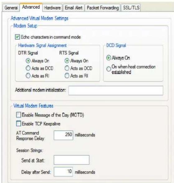
text_image
General Advanced Hardware Email Alert Packet Forwarding SSL/TLS Advanced Virtual Modem Settings Modem Setup Echo characters in command mode Hardware Signal Assignment DTR Signal RTS Signal Always On Always On Acts as DCD Acts as DCD Acts as RI Acts as RI DCD Signal Always On On when host connection established Additional modem initialization: Virtual Modem Features Enable Message of the Day (MOTD) Enable TCP Keepalive AT Command 250 milliseconds Response Delay: millseconds Session Strings: Send at Start: Delay after Send: 10 millisecondsConfigure the following parameters:
Echo characters in command mode When enabled, echoes back characters that are typed in (equivalent to ATE0/ATE1 commands).
Default: Disabled
DTR Signal Always Specify this option to make the DTR signal always act as a DTR signal. On Default: Enabled
DTR Signal Acts as Specify this option to make the DTR signal always act as a DCD signal. DCD Default: Disabled
DTR Signal Acts as Specify this option to make the DTR signal always act as a RI signal. RI Default: Disabled
RTS Signal Always Specify this option to make the RTS signal always act as a RTS signal. On Default: Enabled
RTS Signal Acts as Specify this option to make the RTS signal always act as a DCD signal. DCD Default: Disabled
RTS Signal Acts as Specify this option to make the RTS signal always act as a RI signal. RI Default: Disabled
DCD Signal Always When you configure the DTR or RTS signal pin to act as a DCD signal, enable On this option to make the DCD signal always stay on.
Default: Enabled
DCD Signal On when host connection established When you configure the DTR or RTS signal pin to act as a DCD signal, enable this option to make the DCD signal active only during active communication. Default: Disabled
| Additional modem initialization | You can specify additional virtual modem commands that will affect how virtual modem starts. The following commands are supported: ATQn, ATVn, ATEn, +++ATH, ATA, ATI0, ATI3, ATS0, AT&Z1, AT&Sn, AT&Rn, AT&Cn, AT&F, ATS2, ATS12, ATO (ATD with no phone number), and ATDS1.SeeAppendix C, Virtual Modem AT Commands on page 313for a more detailed explanation of the support initialization commands. |
| Enable Message of the Day (MOTD) | When enabled, displays the Message of the Day (MOTD) when a successful virtual modem connection is made.Default: Disabled |
| Enable TCP Keepalive | Enables a per-connection TCP keepalive feature. After the configured number of seconds, the connection will send a gratuitous ACK to the network peer, thus either ensuring the connection stays active OR causing a dropped connection condition to be recognized.This parameter needs to be used in conjunction withMonitor Connection Status Intervalparameter found in theSerial, Advanced, Advanced Settings tab. The interval specifies the inactivity period before "testing" the connection.Default: Disabled |
| AT Command Response Delay | The amount of time, in milliseconds, before an AT response is sent to the requesting device.Default: 250 ms |
| Session Strings | Controls the sending of ASCII strings to serial devices at session start as follows;Send at Start—If configured, this string will be sent to the serial device on power-up of the IOLAN or when a kill line command is issued on this serial port. If the "monitor DSR" or "monitor DCD" options are set, the string will also be sent when the monitored signal is raised.Range: 0-127 alpha-numeric charactersRange: hex 0-FFDelay after Send—If configured, will inset a delay after the string is sent to the device. This delay can be used to provide the serial device with time to process the string before the session is initiated or terminated.Default: 10 ms |
Phone Number to Host Mapping
If your modem application dials using a phone number, you can add an entry in the Phone Number to Host Mapping window that can be accessed by all serial ports configured as Virtual Modem. You need to enter the phone number sent by your modem application and the IOLAN IP address and TCP Port that will be receiving the “call”. 1-port models support up to 4 entries, all other desktop models support up to 8 entries, and rack mount and medical unit models support up to 48 entries.
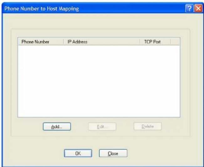
text_image
Phone Number to Host Mapping Phone Number IP Address TCP Fort Add... Ctrl... Delete OK CloseThe following buttons are available:
Add Button
Click the Add button to display a window that allows you to configure the phone number or AT command your modem application sends and the IOLAN's IP address and TCP port number that is receiving the call.
Edit Button
Click on a phone number entry and click the Edit button to change any values configured for the phone number.
Delete Button
Click on a phone number entry and click the Delete button to remove it from the phone number list.
VModem Phone Number Entry
Create an entry in the Phone Number to Host Mapping window.
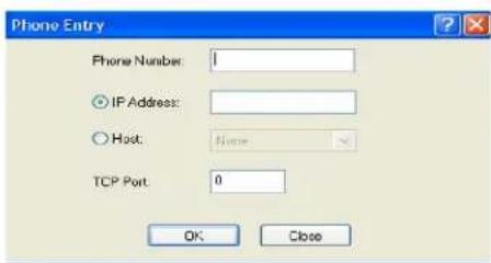
text_image
Phone Entry Phone Number: 0 IP Address: Host: None TCP Port: 0 OK CloseConfigure the following parameters:
Phone Number
Specify the phone number your modem application sends to the modem. Note: The IOLAN does not validate the phone number, so it must be entered in the exact way the application will send it. For example, if you enter 555-1212 in this table and the application sends 5551212, the IOLAN will not match the two numbers. Spaces will be ignored.
| Host IP Address | Specify the IP address of the IOLAN that is receiving the virtual modem connection. |
| Field Format: IPv4 or IPv6 address | |
| Host | Specify the host name (from the host table) of the IOLAN that is receiving the virtual modem connection. |
| TCP Port | Specify the TCP Port on the IOLAN that is set to receive the virtual modem connection. |
| Default: 0 |
Control Signal I/O Profile
Overview
The Control Signal I/O profile is only available on IOLAN I/O models. When you configure a serial port for Control Signal I/O, you are using the DSR, DCD, CTS, DTR, and RTS serial pins for I/O channel Digital Input (DSR, DCD, and CTS) or Digital Output (DTR and RTS).
Functionality
The Control Signal I/O profile enables the use of the EIA-232 serial port pins to be used as assigned Digital Inputs or Digital Outputs.

flowchart
graph TD
    A["IOLAN I/O"] --> B["DB9 Male Connector"]
    B --> C["Ground"]
    B --> D["CTS"]
    B --> E["RTS"]
    B --> F["DCD"]
    B --> G["Digital Input"]
    B --> H["Digital Output"]
    B --> I["DSR"]
    I --> J["Network"]
    J --> K["Monitoring Application"]
General Tab Field Descriptions
The General tab displays the signal pins. This window is also used to enable/disable the signal pins.
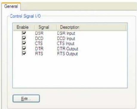
text_image
General Control Signal I/O Enable Signal Description ✓ DSLR DSR Input ✓ DCD DCD Input ✓ CTS CTS Input ✓ DTR DTR Output ✓ RTS RTS Output Edit...Highlight a signal and then click the Edit button to configure the signal pin's parameters.
Input Signal Field Descriptions
See Digital I/O Extension for information about the I/O Extension tab.
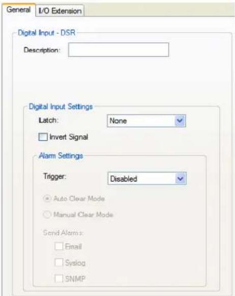
text_image
General I/O Extension Digital Input - DSR Description: Digital Input Settings Latch: None Invert Signal Alarm Settings Trigger: Disabled Auto Clear Mode Manual Clear Mode Send Alarm x Email Syslog SNMPConfigure the following parameters:
Description Provide a description of the channel, making it easier to identify.
Data Options: Maximum 20 characters, including spaces
Latch Latches (remembers) the activity transition (active to inactive or inactive to active).
Data Options: None, Inactive-to-Active, Active-to-Inactive
Default: None
Invert Signal When enabled, inverts the actual condition of the I/O signal in the status; therefore, an inactive status will be displayed as active.
Default: Disabled
Trigger When the trigger condition is met, triggers the specified alarm action.
Data Options:
- Disabled—No alarm settings. This is the default.
- Inactive—When the expected Digital input is active, going inactive will trigger an alarm.
- Active—When the expected Digital input is inactive, going active will trigger an alarm.
Default: Disabled
Auto Clear Mode When enabled, automatically clears the alarm when the trigger condition changes; for example, if the Trigger is Inactive and the alarm is triggered, once the input becomes active again, the alarm will automatically be cleared
Default: Enabled
Manual Clear When enabled, a triggered alarm must be manually cleared.
Mode Default: Disabled
When enabled, sends an email alert to an email account(s) set up in the System settings when an alarm is triggered or cleared. The email alert data includes the severity level and the value that caused the alarm to trigger or clear. The Email Alert is associated with Level Critical.
Default: Disabled
Syslog
When enabled, sends a message to syslog when an alarm is triggered or cleared. The syslog entry includes the severity level and the value that caused the alarm to trigger or clear. The syslog message is associated with Level Critical.
Default: Disabled
SNMP
When enabled, sends an SNMP trap when an alarm is triggered or cleared. The trap consists of the severity level and whether the alarm was triggered or cleared.
Default: Disabled
Output Signal Field Descriptions
See Digital I/O Extension for information about the I/O Extension tab.
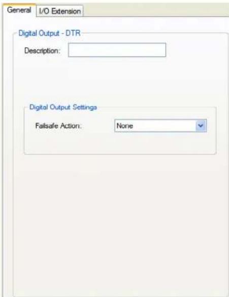
text_image
General I/O Extension Digital Output - DTR Description: Digital Output Settings Fallsafe Action: NoneConfigure the following parameters:
Description
Provide a description of the channel, making it easier to identify.
Data Options: Maximum 20 characters, including spaces
Failsafe Action
When there has been no I/O activity within the specified time (set in the I/O Interfaces, Settings on the Failsafe Timer tab) and the Failsafe Timer is triggered.
Data Options:
- None—The state of the Digital/Relay output remains the same, no change.
• Activate Output—Activates the channel. - Deactivate Output—Deactivates the channel.
Default: None
Modbus Gateway Profile
Overview
Each serial port can be configured as either a Modbus Master gateway or a Modbus Slave gateway, depending on your configuration and requirements. If your model supports I/O, see Modbus I/O Access for more information on using the Modbus protocol to access I/O data.
Functionality
The Modbus Gateway profile configures a serial port to act as a Modbus Master Gateway or a Modbus Slave Gateway.
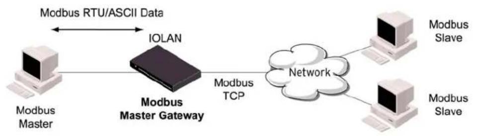
flowchart
graph LR
    A["Modbus Master"] --> B["IOLAN"]
    B --> C["Modbus TCP"]
    C --> D["Network"]
    D --> E["Modbus Slave"]
    D --> F["Modbus Slave"]
    G["Modbus RTU/ASCII Data"] <--> B
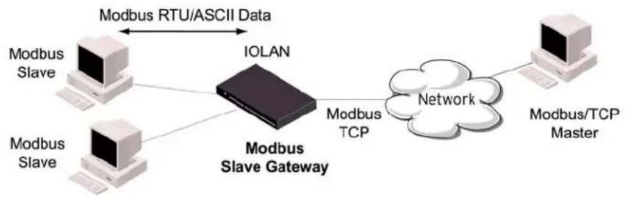
flowchart
graph LR
    A["Modbus Slave"] --> B["Modbus Slave Gateway"]
    C["Modbus Slave"] --> B
    D["Modbus RTU/ASCII Data"] <--> E["IOLAN"]
    B --> F["Modbus TCP"]
    F --> G["Network"]
    G --> H["Modbus/TCP Master"]
General Tab Field Descriptions
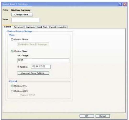
text_image
Serial Port.1 Settings Profile: Modbus Gateway Change Profile Name: General Advanced Hardware Great Net Packet Forwarding Modbus Gateway Settings Profile Modbus Master Destination Since IP Messages Modbus Save UID Range 12:15 IP Address: 172.16.110.22 Advanced Save Settings... Protocol Modbus/RTU Modbus/ASCII Append CIV.12 OK CancelConfigure the following parameters:
| Mode | Specify how the Modbus Gateway is defined on the serial port. Data Options:Modbus Master—Typically, the Modbus Master is connected to the Serial Port and is communicating to Modbus Slaves on the network.Modbus Slave—Typically, the Modbus Master is accessing the IOLAN through the network to communicated to Modbus Slaves connected to the IOLAN’s Serial Ports.Default: Modbus Master Gateway |
| Destination Slave IP Mappings Button | Click this button to launch the Destination Slave IP Settings window, where you can configure the TCP/Ethernet Modbus Slaves that the Modbus Master on the Serial Port will communicate with. |
| Advanced Slave Settings Button | Click this button to configure global Modbus Slave settings. |
| UID Range | You can specify a range of UIDs (1-247), in addition to individual UIDs.Field Format: Comma delimited; for example, 2-35, 50, 100-103 |
| IP Address | Set the IP address to be used for this serial port when using the IP Aliasing feature.See Enable IP Aliasingfor details about how to enable this feature. |
| Modbus/RTU | Select this option when the Modbus/RTU protocol is being used for communication between the Modbus Master and Slave.Default: Enabled |
| Modbus/ASCII | Select this option when Modbus/ASCII protocol is being used for communication between the Modbus Master and Slave.Default: Disabled |
| Append CR/LF | When Modbus/ASCIIis selected, adds a CR/LF to the end of the transmission; most Modbus devices require this option.Default: Enabled |
Advanced Field Descriptions
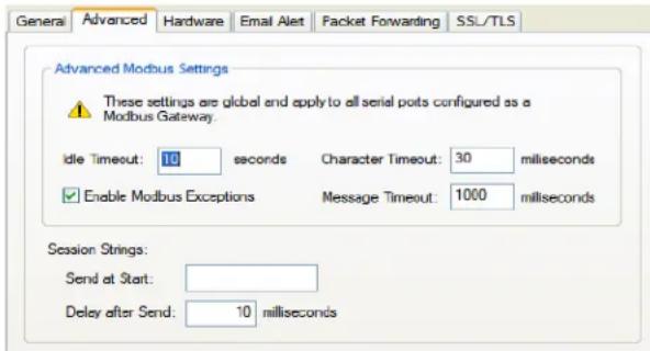
text_image
General Advanced Hardware Email Alert Packet Forwarding SSL/TLS Advanced Modbus Settings These settings are global and apply to all serial ports configured as a Modbus Gateway. Idle Timeout: 10 seconds Character Timeout: 30 milliseconds Enable Modbus Exceptions Message Timeout: 1000 milliseconds Session Strings: Send at Start: Delay after Send: 10 millisecondsConfigure the following parameters:
| Idle Timeout | Use this timer to close a connection because of inactivity. When the IdleTimeout expires, the IOLAN will end the connection.Range: 0-4294967 seconds (about 49 days)Default: 0 (zero), which does not timeout, so the connection is permanently open. |
| Enable Modbus Exceptions | When enabled, an exception message is generated and sent to the initiating Modbus device when any of the following conditions are encountered: there is an invalid UID, the UID is not configured in the Gateway, there is no free network connection, there is an invalid message, or the target device is not answering the connection attempt.Default: Enabled |
| Character Timeout | Used in conjunction with the Modbus RTU protocol, specifies how long to wait, in milliseconds, after a character to determine the end of frame.Range: 10-10000Default: 30 ms |
| Message Timeout | Time to wait, in milliseconds, for a response message from a Modbus TCP or serial slave (depending if the Modbus Gateway is a Master Gateway or Slave Gateway, respectively) before sending a Modbus exception.Range: 10-10000Default: 1000 ms |
| Session Strings | Controls the sending of ASCII strings to serial devices at session start as follows;Send at Start—If configured, this string will be sent to the serial device on power-up of the IOLAN or when a kill line command is issued on this serial port. If the "monitor DSR" or "monitor DCD" options are set, the string will also be sent when the monitored signal is raised.Range: 0-127 alpha-numeric charactersRange: hex 0-FFDelay after Send—If configured, will inset a delay after the string is sent to the device. This delay can be used to provide the serial device with time to process the string before the session is initiated or terminated.Default: 10 ms |
Modbus Slave IP Settings Field Descriptions
This window is used to configure the Modbus Slaves.
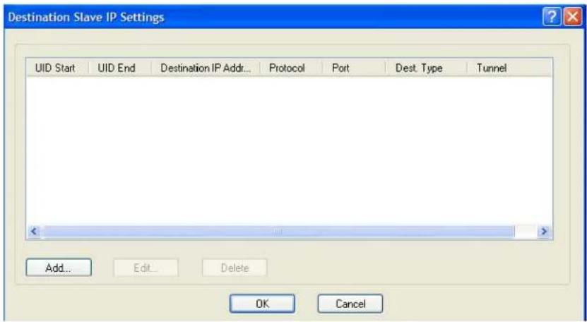
text_image
Destination Slave IP Settings UID Start UID End Destination IP Addr... Protocol Port Dest. Type Tunnel Add... Edit... Delete OK CancelThe following buttons are available:
Add Button Adds an entry into the Modbus Destination Slave IP Settings table.
Edit Button Edits an entry in the Modbus Destination Slave IP Settings table.
Delete Button Deletes an entry from the Modbus Destination Slave IP Settings table.
Adding/Editing Modbus Slave IP Settings
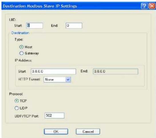
text_image
Destination Modbus Slave IP Settings LID: Start: 0 End: 0 Destination Type: Host Gateway IP Address: Start 0.0.0 End 0.0.0 HTTP Tunnel None Protocol: TCP UDP UDP/TCP Port: 502 OK CancelConfigure the following parameters:
UID Start
When Destination is set to Host and you have sequential Modbus Slave IP addresses (for example, 10.10.10.1, 10.10.10.2, 10.10.10.3, etc.), you can specify a UID range (not supported with IPv6 addresses) and the IOLAN will automatically increment the last digit of the configured IP address. Therefore, you can specify a UID range of 1-100, and the IOLAN will route Master Modbus messages to all Modbus Slaves with IP addresses of 10.10.10.1 - 10.10.10.100.
Range: 1-247
Default: 0 (zero)
UID End
When Destination is set to Host and you have sequential Modbus Slave IP addresses (for example, 10.10.10.1, 10.10.10.2, 10.10.10.3, etc.), you can specify a UID range (not supported with IPv6 addresses) and the IOLAN will automatically increment the last digit of the configured IP address. Therefore, you can specify a UID range of 1-100, and the IOLAN will route Master Modbus messages to all Modbus Slaves with IP addresses of 10.10.10.1 - 10.10.10.100.
Range: 1-247
Default: 0 (zero)
Type
Specify the configuration of the Modbus Slaves on the network.
Data Options:
- Host—The IP address is used for the first UID specified in the range. The last octet in the IPv4 address is then incremented for subsequent UID's in that range.
- Gateway—The Modbus Master Gateway will use the same IP address when connecting to all the remote Modbus slaves in the specified UID range.
Default: Host
Start IP Address
The IP address of the TCP/Ethernet Modbus Slave.
Field Format: IPv4 or IPv6 address
End IP Address
Displays the ending IP address of the TCP/Ethernet Modbus Slaves, based on the Start IP address and the UID range (not supported for IPv6 addresses).
Field Format: IPv4 address
HTTP Tunnel Specify the HTTP tunnel to be used for this connection.
Protocol Specify the protocol that is used between the Modbus Master and Modbus Slave(s).
Data Options: TCP or UDP
Default: TCP
UDP/TCP Port The destination port of the remote Modbus TCP Slave that the IOLAN will connect to.
Range: 0-65535
Default: 502
Modbus Slave Advanced Settings Field Descriptions
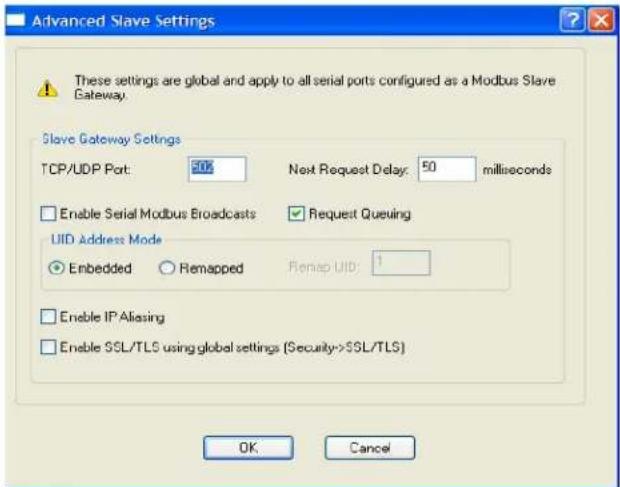
text_image
Advanced Slave Settings These settings are global and apply to all serial ports configured as a Modbus Slave Gateway. Slave Gateway Settings TCP/UDP Port: 20% Next Request Delay: 50 milliseconds Enable Serial Modbus Broadcasts Request Queuing UUID Address Mode Embedded Remapped Remap UID: 1 Enable IP Aliasing Enable SSL/TLS using global settings (Security->SSL/TLS) OK CancelConfigure the following parameters:
TCP/UDP Port
The network port number that the Slave Gateway will listen on for both TCP and UDP messages.
Default: 502
Next Request Delay A delay, in milliseconds, to allow serial slave(s) to re-enable receivers before issuing next Modbus Master request.
Range: 0-1000
Default: 50 ms
Enable Serial When enabled, a UID of 0 (zero) indicates that the message will be broadcast to Modbus Broadcasts all Modbus Slaves.
Default: Disabled
Request Queuing
When enabled, allows multiple, simultaneous messages to be queued and processed in order of reception.
Default: Enabled
Embedded When this option is selected, the address of the slave Modbus device is embedded in the message header.
Default: Enabled
Remapped Used for single device/port operation. Older Modbus devices may not include a UID in their transmission header. When this option is selected, you can specify the UID that will be inserted into the message header for the Modbus slave device. This feature supersedes the Broadcast feature.
Default: Disabled
Remap UID Specify the UID that will be inserted into the message header for the Slave Modbus serial device.
Range: 1-247
Default: 1
Enable IP Aliasing When enabled, allows for multiple requests to serial slaves (from an Ethernet Master/s) to be processed simultaneously.
Default: Off
See IP Address for details about setting the IP address to be used with this serial port.
Enable SSL/TLS When enabled, Modbus Slave Gateway messages to remote TCP Modbus using global Masters are encrypted via SSL/TLS.
settings
Default: Disabled
Power Management Profile
Overview
The Power Management profile applies when there is a Perle Remote Power Switch (RPS) connected to the serial port. This profile is used to configure the RPS. See RPS Control for information on how to actively management the RPS.
Functionality
The Power Management profile configures a serial port to communicate with a Remote Power Switch's (RPS) administration port. This allows network access to the RPS and permits access to statistics and control of the RPS's power plugs.
General Tab Field Descriptions
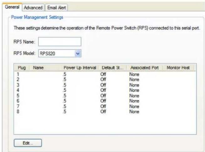
text_image
General Advanced Email Alert Power Management Settings These settings determine the operation of the Remote Power Switch (RPS) connected to this serial port. RPS Name: RPS Model: RPS820 Plug Name Power Up Interval Default St... Associated Port Monitor Host 1 .5 Off None 2 .5 Off None 3 .5 Off None 4 .5 Off None 5 .5 Off None 6 .5 Off None 7 .5 Off None 8 .5 Off None Edit ..Configure the following parameters:
RPS Name Specify a name for the RPS.
RPS Model Specify the RPS model.
Data Options: RSP820, RPS830, RPS1620, RPS1630
Default: RSP820
Edit Button Highlight a plug and then click the Edit button to configure the plug.
Advanced Tab Field Descriptions
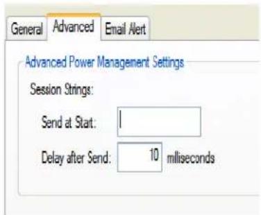
text_image
General Advanced Email Alert Advanced Power Management Settings Session Strings: Send at Start: 1 Delay after Send: 10 millisecondsConfigure the following parameters:
Session Strings
Controls the sending of ASCII strings to serial devices at session start as follows;
- Send at Start—If configured, this string will be sent to the serial device on power-up of the IOLAN or when a kill line command is issued on this serial port. If the "monitor DSR" or "monitor DCD" options are set, the string will also be sent when the monitored signal is raised.
Range: 0-127 alpha-numeric characters
Range: hex 0-FF
- Delay after Send—If configured, will inset a delay after the string is sent to the device. This delay can be used to provide the serial device with time to process the string before the session is initiated or terminated.
Default: 10 ms
Editing Power Management Plug Settings Field Descriptions
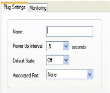
text_image
Plug Settings Monitoring Name: 1 Power Up Interval: .5 seconds Default State: Off Associated Port: NoneConfigure the following parameters:
Name Specify a name for the plug to make it easier to recognize and manage.
Power Up Interval Specify the amount of time, in seconds, that the RPS will wait before powering up a plug. This can be useful if you have peripherals that need to be started in a specific order.
Data Options: .5, 1, 2, 5, 15, 30, 60, 120, 180, 300
Default: .5 seconds
Default State Sets the default state of the plug.
Data Options: On, Off
Default: Off
Associated Port When a server or router has its console port connected to one of the serial ports on this IOLAN and that server/router is also powered by this RPS, the server/router serial port number should be entered here. This will give you direct access to some RPS commands when managing that server or router (using Telnet or SSH).
Monitoring Tab Field Descriptions
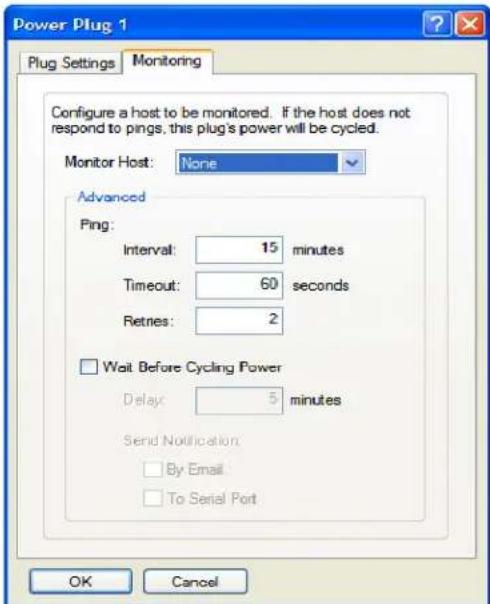
text_image
Power Plug 1 Plug Settings Monitoring Configure a host to be monitored. If the host does not respond to pings, this plug's power will be cycled. Monitor Host: None Advanced Ping: Interval: 15 minutes Timeout: 60 seconds Retnes: 2 Wait Before Cycling Power Delay: 5 minutes Send Notification: By Email To Serial Port OK CancelConfigure the following parameters:
Monitor Host
This is the host which is to be monitored via PINGs. If the host stops responding to the PINGs, the power on this plug will be cycled in an attempt to recover the host.
Default: None
Ping
- Interval -Specify the frequency ( in minutes ) at which the configured host will be PING'ed.
Default - 15 minutes
- Timeout - Specify the length of time (in seconds) to wait for a reply
Default - 60 seconds
- Retries - Specify the number of times to re-try the PING when the host does not reply. This is in addition to the orginal PING request.
Default - 2
Wait Before Cycling Power
Enables a delay before cycling the power on the plug. This delay allows for the sending of notification(s) of the impending power cycle. Notifications can be sent to a user on the console port of the host being monitored and/or via email. This gives system administrators the time to take appropriate action.
Default: Disabled
- Delay—Specify a delay (in minutes) before cycling the power on the plug. Default - 5 Minutes
Send Notification—Specify the desired notification to be sent advising of the impending power cycle.
- By Email—Send an email. Details configured in “Email Alert” tab.
- To Serial Port—Send a message to the serial port associated with this power plug. This is usually the console port on the host being monitored.
Remote Access (PPP) Profile
Overview
The Remote Access (PPP) profile configures a serial port to allow a remote user to establish a PPP connection to the IOLAN's serial port. This is typically used with a modem for dial-in or dial-out access to the network or a wireless WAN card.
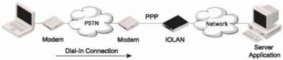
flowchart
graph LR
    A["Laptop"] --> B["Modem"]
    B --> C["PSTN"]
    C --> D["Modem"]
    D --> E["IOLAN"]
    E --> F["Network"]
    F --> G["Server Application"]
    H["Dial-In Connection"] --> E
Functionality
There are two options for PPP user authentication:
- You can configure a specific user/password and a specific remote user/password per a serial port.
- You can create a secrets file with multiple users and their passwords that will globally authenticate users on all serial ports.
You can use configure PPP authentication in the configuration or in the secrets file, but not both.
If you want to use a secrets file, you must download the secrets file to the IOLAN for CHAP or PAP authentication; the files must be downloaded to the IOLAN using the names chap-secrets and pap-secrets, respectively. The file can be downloaded to the IOLAN under the Custom Files option by selecting the Download Other File parameter.
In the Remote Access (PPP) profile, you must also specify the Authentication option as PAP or CHAP on the Authentication tab, but must leave the User, Password, Remote User, and Remote Password fields blank.
An example of the CHAP secrets file follows:
| # Secrets for authentication using CHAP | |||
| # client | server | secret | acceptable local IP addresses |
| barney | fred | flintstone1234567890 | 192.168.43.1 |
| fred | barney | wilma | 192.168.43.2 |
An example of the PAP secret file follows:
| Secrets for authentication using PAP | |||
| client | server | secret | acceptable local IP addresses |
| barney | * | flintstone1234567890 | |
| fred | * | wilma | |
General Tab Field Descriptions
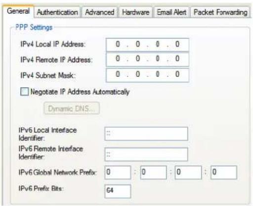
text_image
General Authentication Advanced Hardware Email Alert Packet Forwarding PPP Settings IPv4 Local IP Address: 0 . 0 . 0 . 0 IPv4 Remote IP Address: 0 . 0 . 0 . 0 IPv4 Subnet Mask: 0 . 0 . 0 . 0 □ Negotiate IP Address Automatically Dynamic DNS... IPv6 Local Interface Identifier: : : IPv6 Remote Interface Identifier: : : IPv6 Global Network Prefix: 0 : 0 : 0 : 0 IPv6 Prefix Bits: 64Configure the following parameters:
| IPv4 Local IP Address | The IPV4 IP address of the IOLAN end of the PPP link. For routing to work, you must enter a local IP address. Choose an address that is part of the same network or subnetwork as the remote end; for example, if the remote end is address 192.101.34.146, your local IP address can be 192.101.34.145. Do not use the IOLAN's (main) IP address in this field; if you do so, routing will not take place correctly. |
| IPv4 Remote IP Address | The IPV4 IP address of the remote end of the PPP link. Choose an address that is part of the same network or subnetwork as the IOLAN. If you set the PPP parameter IP Address Negotiation to On, the IOLAN will ignore the remote IP address value you enter here and will allow the remote end to specify its IP address. If your user is authenticated by RADIUS and the RADIUS parameter Framed-Addressis set in the RADIUS file, the IOLAN will use the value in the RADIUS file in preference to the value configured here. The exception to this rule is a Framed-Addressvalue in the RADIUS file of 255.255.255.254; this value allows the IOLAN to use the remote IP address value configured here. |
| IPv4 Subnet Mask | The network subnet mask. For example, 255.255.0.0. If your user is authenticated by RADIUS and the RADIUS parameter Framed-Netmaskis set in the RADIUS file, the IOLAN will use the value in the RADIUS file in preference to the value configured here. |
| Negotiate IP Address Automatically | Specifies whether or not IP address negotiation will take place. IP address negotiation is where the IOLAN allows the remote end to specify its IP address. When On, the IP address specified by the remote end will be used in preference to the Remote IP Addressset for a Serial Port. When Off, the Remote IP Addressset for the Serial Portwill be used.Default: Disabled |
| Dynamic DNS Button | Launches the Dynamic DNS window when IP Address Negotiation is enabled, which can then update the DNS server with the IP address that is negotiated and accepted for the PPP session. |
IPv6 Local Interface Identifier
The local IPv6 interface identifier of the IOLAN end of the PPP link. For routing to work, you must enter a local IP address. Choose an address that is part of the same network or subnetwork as the remote end. Do not use the IOLAN's (main) IP address in this field; if you do so, routing will not take place correctly.
Field Format: The first 64 bits of the Interface Identifier must be zero, therefore, ::abcd:abcd:abcd:abcd is the expected format.
IPv6 Remote Interface Identifier
The remote IPv6 interface identifier of the remote end of the PPP link. Choose an address that is part of the same network or subnetwork as the IOLAN. If you enable Negotiate IP Address Automatically, the IOLAN will ignore the remote IP address value you enter here and will allow the remote end to specify its IP address. If your user is authenticated by RADIUS and the RADIUS parameter Framed-Interface-ID is set in the RADIUS file, the IOLAN will use the value in the RADIUS file in preference to the value configured here.
Field Format: The first 64 bits of the Interface Identifier must be zero, therefore, ::abcd:abcd:abcd:abcd is the expected format.
IPv6 Global Network Prefix
You can optionally specify an IPv6 global network prefix that the IOLAN will advertise to the device at the other end of the PPP link.
Default: 0:0:0:0
IPv6 Prefix Bits Specify the prefix bits for the IPv6 global network prefix.
Default: 64
Dynamic DNS Field Descriptions
Dynamic DNS can be enabled and configured on a serial port level. If you enable Dynamic DNS and leave the parameters blank, the Dynamic DNS system parameters will be used (Network, Advanced, Dynamic DNS tab).
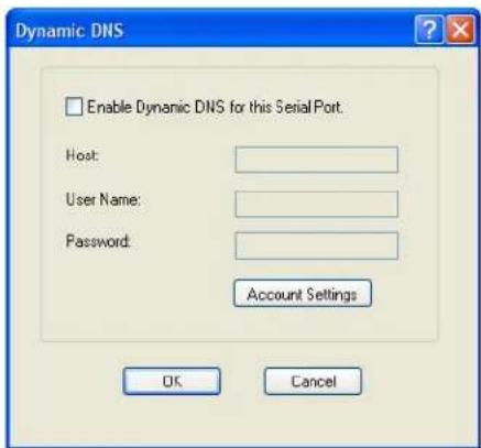
text_image
Dynamic DNS Enable Dynamic DNS for this Serial Port. Host: User Name: Password: Account Settings OK CancelConfigure the following parameters:
Enable Dynamic DNS for this Serial Port
Enables/disables the ability to register a new IP address with the DNS server. Default: Disabled
Host Specify the host name that will be updated with the PPP session's IP address on the DNS server.
User Name Specify the user name used to access the DNS server.
Password Specify the password used to access the DNS server.
Account Settings Button
Click this button to configure the Dynamic DNS DynDNS.org account information.
See Account Settings for information on how to configure the Account Settings window.
Authentication Tab Field Descriptions
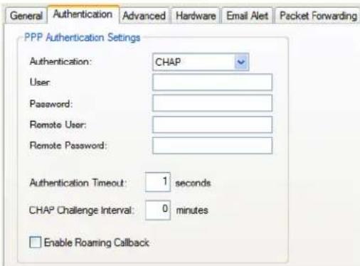
text_image
General Authentication Advanced Hardware Email Alert Packet Forwarding PPP Authentication Settings Authentication: CHAP User: Password: Remote User: Remote Password: Authentication Timeout: 1 seconds CHAP Challenge Interval: 0 minutes Enable Roaming CallbackConfigure the following parameters:
Authentication
The type of authentication that will be done on the link. You can use PAP or CHAP (MD5-CHAP, MS-CHAPv1 and MS-CHAPv2) to authenticate a user or client on the IOLAN. When setting either PAP and CHAP, make sure the IOLAN and the PPP peer, have the same setting. For example, if the IOLAN is set to PAP, but the remote end is set to CHAP, the connection will be refused.
Data Options:
None - no authentication will be performed.
PAP—is a one time challenge of a client/device requiring that it respond with a valid username and password. A timer operates during which successful authentication must take place. If the timer expires before the remote end has been authenticated successfully, the link will be terminated.
CHAP—challenges a client/device at regular intervals to validate itself with a username and a response, based on a hash of the secret (password). A timer operates during which successful authentication must take place. If the timer expires before the remote end has been authenticated successfully, the link will be terminated. MD5-CHAP and Microsoft MS-CHAPv1/MS-CHAPv2 are supported. The IOLAN will attempt MS-CHAPv2 with MPPC compression, but will negotiate to the variation of CHAP, compression and encryption that the remote peer wants to use.
Default: CHAP
User
Complete this field only if you have specified PAP or CHAP (security protocols) in the Authentication field, and
- you wish to dedicate this line to a single remote user, who will be authenticated by the IOLAN, or
- you are using the IOLAN as a router (back-to-back with another IOLAN).
When Connect is set to Dial Out or both Dial In/Dial Out are enabled, the User is the name the remote device will use to authenticate a port on this IOLAN. The remote device will only authenticate your IOLAN's port when PAP or CHAP are operating. You can enter a maximum of sixteen alphanumeric characters; for example, tracy201. When connecting together two networks, enter a dummy user name; for example, DS_HQ.
Note If you want a reasonable level of security, the user name and password should not be similar to a user name or password used regularly to login to the IOLAN. External authentication can not be used for this user.
Field Format: You can enter a maximum of 254 alphanumeric characters.
Password
Complete this field only if you have specified PAP or CHAP (security protocols) in the Security field and:
- you wish to dedicate this serial port to a single remote user, who will be authenticated by the IOLAN, or
- you are using the IOLAN as a router (back-to-back with another IOLAN)
Password means the following: - When PAP is specified, this is the password the remote device will use to authenticate the port on this IOLAN.
- When CHAP is specified, this is the secret (password) known to both ends of the link upon which responses to challenges shall be based.
Field Format: You can enter a maximum of 16 alphanumeric characters.
Remote User
Complete this field only if you have specified PAP or CHAP (security protocols) in the Security field, and
- you wish to dedicate this line to a single remote user, who will be authenticated by the IOLAN, or
- you are using the IOLAN as a router (back-to-back with another IOLAN)
When Dial In or Dial In/Dial Out is enabled, the Remote User is the name the IOLAN will use to authenticate the port on the remote device. Your IOLAN will only authenticate the port on the remote device when PAP or CHAP are operating. When connecting together two networks, enter a dummy user name; for example, DS_SALES.
Note If you want a reasonable level of security, the user name and password should not be similar to a user name or password used regularly to login to the IOLAN. This option does not work with external authentication.
Field Format: You can enter a maximum of 254 alphanumeric characters.
| Remote Password | Complete this field only if you have specified PAP or CHAP (security protocols) in the Security field, andyou wish to dedicate this serial port to a single remote user, and this user will be authenticated by the IOLAN, oryou are using the IOLAN as a router (back-to-back with another IOLAN)Remote password means the following:When PAP is specified, this is the password the IOLAN will use to authenticate the remote device.When CHAP is specified, this is the secret (password) known to both ends of the link upon which responses to challenges will be based.Remote Password is the opposite of the parameter Password. Your IOLAN will only authenticate the remote device when PAP or CHAP is operating.Field Format: You can enter a maximum of 16 alphanumeric characters. |
| Authentication Timeout | The timeout, in minutes, during which successful PAP or CHAP authentication must take place (when PAP or CHAP are specified). If the timer expires before the remote end has been authenticated successfully, the link will be terminated.Range: 1-255Default: 1 minute |
| CHAP Challenge Interval | The interval, in minutes, for which the IOLAN will issue a CHAP re-challenge to the remote end. During CHAP authentication, an initial CHAP challenge takes place, and is unrelated to CHAP re-challenges. The initial challenge takes place even if re-challenges are disabled. Some PPP client software does not work with CHAP re-challenges, so you might want to leave the parameter disabled in the IOLAN.Range: 0-255Default: 0 (zero), meaning CHAP re-challenge is disabled |
| Enable Roaming Callback | A user can enter a telephone number that the IOLAN will use to callback him/her. This feature is particularly useful for a mobile user. Roaming callback can only work when the User Enable Callback parameter is enabled. Enable Roaming Callback therefore overrides (fixed) User Enable Callback. To use Enable Roaming Callback, the remote end must be a Microsoft Windows OS that supports Microsoft’s Callback Control Protocol (CBCP). The user is allowed 30 seconds to enter a telephone number after which the IOLAN ends the call.Default: Disabled |
Advanced Tab Field Descriptions
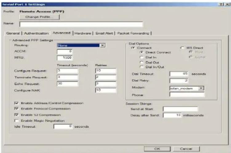
text_image
Serial Part 1 Settings Profile: Remote Access (PPP) Change Profile: Name: General Authentication Advanced Hardware Email Alert Packet Forwarding Advanced PPP Settings Reading: None ACCM: 0 MRU: 1500 Configure Request: 3 Retrie Terminate Request: 2 Echo Request: 3 Configure NAK: 10 Enable Address/Control Compression Enable Protocol Compression Enable VJ Compression Enable Magic Negotiation Idle Timeout: 0 seconds Dial Options Connect MS Direct Direct Connect Host Dial In Dial Out Dial In/Out Dial Timeout: 45 seconds Dial Retry: 2 Modem: iolar_modem Phone: Session Strings: Send at Start: Delay after Send: 10 milliseconds OK CancelConfigure the following parameters:
Routing Determines the routing mode (RIP, Routing Information Protocol) used on the
PPP interface. This is the same function as the Framed-Routing attribute for RADIUS authenticated users.
Data Options
• None—Disables RIP over the PPP interface.
- Send—Sends RIP over the PPP interface.
- Listen—Listens for RIP over the PPP interface.
- Send and Listen—Sends RIP and listens for RIP over the PPP interface.
Default: None
ACCM
Specifies the ACCM (Asynchronous Control Character Map) characters that should be escaped from the data stream.
Field Format: This is entered as a 32-bit hexadecimal number with each bit specifying whether or not the corresponding character should be escaped. The bits are specified as the most significant bit first and are numbered 31-0. Thus if bit 17 is set, the 17th character should be escaped, that is, 0x11 (XON). The value 000a0000 will cause the control characters 0x11 (XON) and 0x13 (XOFF) to be escaped on the link, thus allowing the use of XON/XOFF (software) flow control. If you have selected Soft Flow Control on the Serial Port, you must enter a value of at least 000a0000 for the ACCM.
Default: 00000000, which means no characters will be escaped
MRU
The Maximum Receive Unit (MRU) parameter specifies the maximum size of PPP packets that the IOLAN's port will accept. If your user is authenticated by the IOLAN, the MRU value will be overridden if you have set a MTU value for the user. If your user is authenticated by RADIUS and the RADIUS parameter Framed-MTU is set in the RADIUS file, the IOLAN will use the value in the RADIUS file in preference to the value configured here.
Range: 64-1500 bytes
Default: 1500
| Configure RequestTimeout | The maximum time, in seconds, that LCP (Link Control Protocol) will wait before it considers aconfigure requestpacket to have been lost.Range: 1-255Default: 3 seconds |
| Configure RequestRetries | The maximum number of times aconfigure requestpacket will be re-sent before the link is terminated.Range: 0-255Default: 10 seconds |
| Terminate RequestTimeout | The maximum time, in seconds, that LCP (Link Control Protocol) will wait before it considers aterminate requestpacket to have been lost.Range: 1-255Default: 3 seconds |
| Terminate RequestRetries | The maximum number of times aterminate requestpacket will be re-sent before the link is terminated.Range: 0-255Default: 2 seconds |
| Echo RequestTimeout | The maximum time, in seconds, between sending anechorequest packet if no response is received from the remote host.Range: 0-255Default: 30 seconds |
| Echo RequestRetries | The maximum number of times anechorequest packet will be re-sent before the link is terminated.Range: 0-255Default: 3 |
| Configure NAKRetries | The maximum number of times aconfigure NAKpacket will be re-sent before the link is terminated.Range: 0-255Default: 10 seconds |
| EnableAddress/ControlCompression | This determines whether compression of thePPP AddressandControlfields take place on the link. For most applications this should be enabled.Default: Enabled |
| Enable ProtocolCompression | This determines whether compression of the PPP Protocol field takes place on this link.Default: Enabled |
| Enable VJCompression | When enabled, Van Jacobson Compression is used on this link. If your user is authenticated by the IOLAN, this VJ compression value will be overridden if you have enabled theUser, Enable VJ Compressionparameter. If the user is authenticated by RADIUS andthe RADIUS parameterFramed-Compressionis set in the RADIUS file, the IOLAN will use the value in the RADIUS file in preference to the value configured here.Default: Enabled |
| Enable Magic Negotiation | Determines if a line is looping back. If enabled (On), random numbers are sent on the link. The random numbers should be different, unless the link loops back.Default: Disabled |
| Idle Timeout | Use this timer to close a connection because of inactivity. When the IdleTimeout expires, the IOLAN will end the connection.Range: 0-4294967 seconds (about 49 days)Default: 0 (zero), which does not timeout, so the connection is permanently open. |
| Direct Connect | Specify this option when a modem is not connected to this serial port.Default: Enabled |
| Dial In If the device is remote and will be dialing in via modem or ISDN TA, enable this parameter.Default: Disabled | |
| Dial Out | If you want the modem to dial a number when the serial port is started, enable this parameter.Default: Disabled |
| Dial In/Out | Enable this option when you want the serial port to do either of the following:accept a call from a modem or ISDN TAdial a number when the serial port is startedDefault: Disabled |
| MS Direct Host | Specify this option when the serial port is connected to a Microsoft Guest device.Default: Enabled |
| MS Direct Guest | Enable this option when the serial port is connected to a Microsoft Host device.Default: Disabled |
| Dial Timeout | The number of seconds the IOLAN will wait to establish a connection to a remote modem.Range: 1-99Default: 45 seconds |
| Dial Retry | The number of times the IOLAN will attempt to re-establish a connection with a remote modem.Range: 0-99Default: 2 |
| Modem The name of the predefined modem that is used on this line. | |
| Phone | The phone number to use when Dial Out is enabled. |
Session Strings
Controls the sending of ASCII strings to serial device at session start as follows;
- Send at Start—If configured, this string will be sent to the serial device on power-up of the IOLAN, or when a kill line command is issued on this serial port. If the "monitor DSR" or "monitor DCD" options are set, the string will also be sent when the monitored signal is raised.
Range: 0-127 alpha-numeric characters
Range: hexadecimal 0-FF
- Delay after Send - If configured, will inset a delay after the string is sent to the device. This delay can be used to provide the serial device with time to process the string before the session is initiated.
Default: 10 ms
Remote Access (SLIP) Profile
Overview
The Remote Access (SLIP) profile configures a serial port to allow a remote user to establish a SLIP connection to the IOLAN's serial port. This is typically used with a modem for dial-in or dial-out access to the network.
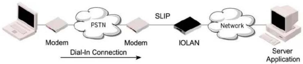
flowchart
graph LR
    A["Laptop"] --> B["Modem"]
    B --> C["PSTN"]
    C --> D["Modem"]
    D --> E["SLIP"]
    E --> F["IOLAN"]
    F --> G["Network"]
    G --> H["Server Application"]
    I["Dial-In Connection"] --> B
General Tab Field Descriptions
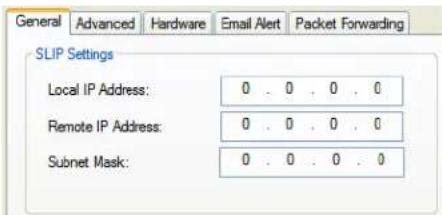
text_image
General Advanced Hardware Email Alert Packet Forwarding SLIP Settings Local IP Address: 0 . 0 . 0 . 0 Remote IP Address: 0 . 0 . 0 . 0 Subnet Mask: 0 . 0 . 0 . 0Configure the following parameters:
Local IP Address
The IPv4 address of the IOLAN end of the SLIP link. For routing to work you must enter an IP address in this field. Choose an address that is part of the same network or subnetwork as the remote end; for example, if the remote end is address 192.101.34.146, your local IP address can be 192.101.34.145. Do not use the IOLAN's (main) IP address in this field; if you do so, routing will not take place correctly.
Remote IP Address
The IPv4 address of the remote end of the SLIP link. Choose an address that is part of the same network or subnetwork as the IOLAN. If your user is authenticated by the IOLAN, this remote IP address will be overridden if you have set a Framed IP Address for the user. If your user is authenticated by RADIUS and the RADIUS parameter Framed-Address is set in the RADIUS file, the IOLAN will use the value in the RADIUS file in preference to the value configured here.
Subnet Mask
The network subnet mask. For example, 255.255.0.0. If your user is authenticated by RADIUS and the RADIUS parameter Framed-Netmask is set in the RADIUS file, the IOLAN will use the value in the RADIUS file in preference to the value configured here.
Advanced Tab Field Descriptions
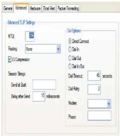
text_image
General Advanced Hardware Email Alert Packet Forwarding Advanced SLIP Settings MTU: Routing: None VJ Compression Session Strings: Send at Start: Delay after Send: 10 milliseconds Dial Options Direct Connect Dial In Dial Out Dial In/Out Dial Timeout: 45 seconds Dial Retry: 2 Modern: Phone:Configure the following parameters:
MTU The Maximum Transmission Unit (MTU) parameter restricts the size of individual SLIP packets being sent by the IOLAN. Enter a value between 256 and 1006 bytes; for example, 512. The default value is 256. If your user is authenticated by the IOLAN, this MTU value will be overridden when you have set a Framed MTU value for the user. If your user is authenticated by RADIUS and the RADIUS parameter Framed-MTU is set in the RADIUS file, the IOLAN will use the value in the RADIUS file in preference to the value configured here.
Default: 256
Routing Determines the routing mode (RIP, Routing Information Protocol) used on the SLIP interface as one of the following options:
• None—Disables RIP over the SLIP interface.
- Send—Sends RIP over the SLIP interface.
- Listen—Listens for RIP over the SLIP interface.
- Send and Listen—Sends RIP and listens for RIP over the SLIP interface.
This is the same function as the Framed-Routing attribute for RADIUS authenticated users.
Default: None
VJ Compression When enabled, Van Jacobson compression is used on this link. When enabled, C-SLIP, or compressed SLIP, is used. When disabled, plain SLIP is used. C-SLIP greatly improves the performance of interactive traffic, such as Telnet or Rlogin.
If your user is authenticated by the IOLAN, this VJ compression value will be overridden if you have set a Framed Compression value for a user. If your user is authenticated by RADIUS and the RADIUS parameter Framed-
Compression is set in the RADIUS file, the IOLAN will use the value in the RADIUS file in preference to the value configured here.
Default: Enabled
| Session Strings | Controls the sending of ASCII strings to serial device at session start as follows;Send at Start-If configured, this string will be sent to the serial device on power-up of the IOLAN, or when a kill line command is issued on this serial port. If the "monitor DSR" or "monitor DCD" options are set, the string will also be sent when the monitored signal is raised.Range: 0-127 alpha-numeric charactersRange: hexadecimal 0-FFDelay after Send - If configured, will inset a delay after the string is sent to the device. This delay can be used to provide the serial device with time to process the string before the session is initiated.Default: 10 ms |
| Direct Connect | If the device is remote and will be dialing in via modem or ISDN TA, enable this parameter.Default: Disabled |
| Dial In If the device is remote and will be dialing in via modem or ISDN TA, enable this parameter.Default: Disabled | |
| Dial Out | If you want the modem to dial a number when the serial port is started, enable this parameter.Default: Disabled |
| Dial In/Out | Enable this option when you want the serial port to do either of the following:accept a call from a modem or ISDN TAdial a number when the serial port is startedDefault: Disabled |
| Dial Timeout | The number of seconds the IOLAN will wait to establish a connection to a remote modem.Range: 1-99Default: 45 seconds |
| Dial Retry | The number of times the IOLAN will attempt to re-establish a connection with a remote modem.Range: 0-99Default: 2 |
| Modcm The name of the predefined modem that is used on this line. | |
| Phone | The phone number to use when Dial Out is enabled. |
Custom Application Profile
Overview
The Custom App/Plugin profile is used in conjunction with custom applications created for the IOLAN by using the Perle SDK. See the SDK Programmer's Guide (the SDK and guide are accessible via a request form located on the Perle website at
www.perle.com/supportfiles/SDK_Request.shtml) for information about the functions that are supported.
Functionality
You must download the program and any ancillary files to the IOLAN and set the serial port to the Custom App/Plugin profile to actually run a custom application. You must also specify the program executable and any parameters you want to pass to the program in the Command Line field. The custom application is automatically run when the serial port is started.
General Tab Field Description
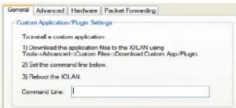
text_image
General Advanced Hardware Packet Forwarding Custom Application/Plugin Settings To install a custom application: 1) Download the application file to the IOLAN using Tools->Advanced->Custom Files->Download Custom App./Plugin. 2) Set the command line below. 3) Reboot the IOLAN. Command Line: 1Configure the following parameter:
Command Line
The name of the SDK program executable that has been already been downloaded to the IOLAN, plus any parameters you want to pass to the program. Use the shell CLI command as described in the SDK Programmer's Guide to manage the files that you have downloaded to the IOLAN. For example, using sample outraw program, you would type:
outraw 192.168.2.1:10001 Acct:10001
if you were starting the application on a serial port.
Field Format: Maximum of 80 characters
Advanced Tab Field Description
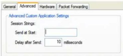
text_image
General Advanced Hardware Packet Forwarding Advanced Custom Application Settings Session Strings: Send at Start: 1 Delay after Send: 10 millisecondsConfigure the following parameter:
Session Strings
Controls the sending of ASCII strings to serial device at session start as follows;
- Send at Start—If configured, this string will be sent to the serial device on power-up of the IOLAN, or when a kill line command is issued on this serial port. If the "monitor DSR" or "monitor DCD" options are set, the string will also be sent when the monitored signal is raised.
Range: 0-127 alpha-numeric characters
Range: hexadecimal 0-FF
- Delay after Send - If configured, will inset a delay after the string is sent to the device. This delay can be used to provide the serial device with time to process the string before the session is initiated.
Default: 10 ms
Port Buffering
Overview
The Port Buffering feature allows data activity on the IOLAN's serial ports to be held in memory for viewing at a later stage without affecting the normal operation of the serial ports.
Port Buffering is only supported on serial port(s) configured for the Console Management profile.
Functionality
Port Buffering is required by system administrators to capture important information from devices attached to the IOLAN. If a device (such as a Router) has a problem and sends a warning message out of its console port while no one is connected, the warning can be lost. With Port Buffering enabled, the messages will be captured in memory or in a file and can be viewed later to aid administrators in diagnosing and fixing problems.
Local Port Buffering
Port buffer information for the serial port can be viewed after successful connection to a device on a serial port. The user can toggle between communicating to the device on the serial port and viewing the port buffer data for that device by entering a the View Buffer String (default \~view). Local port buffering is limited to 256Kb and will be flushed after the IOLAN reboots.
To view the local port buffer for a particular serial port, you must:
- Connect to the device on that serial port by Telnet or SSH (the serial port(s) must be set to the Console Management profile to support this type of connection).
- Once you have established a connection to a device, you can enter the View Buffer String at any time to switch the display to the content of the port buffer for that particular serial port.
- To return to communicating to the device, press the ESC key and the communication session will continue from where you left off.
To navigate through the port buffer data, the following chart illustrates the keyboard keys or “hot keys” that can be used to view the port buffer data. Press the ESC key and to continue to communicate with the device on that particular serial port.
| Keyboard Buttons Hot Keys Direction | |
| Page UpB Up | |
| Page DownF Down | |
| HomeT Top of the buffer data (oldest data) | |
| EndE Bottom of the buffer (latest data) | |
| ESC Exit viewing port buffer data. |
Remote Port Buffers
The Remote Port Buffering feature allows data received from serial ports on the IOLAN to be sent to a remote server on the LAN. The remote server, supporting Network File System (NFS), allows administrators to capture and analyze data and messages from the serial device connected to the IOLAN serial port.
Remote Port Buffering data can be encrypted or raw and/or time stamped. The data is transmitted to an NFS server where a unique remote file is created for each serial port using the configured serial port Name for the file name. If the serial port Name parameter is left blank, the IOLAN will create unique files using the IOLAN's Ethernet MAC address and serial port number. It is recommended that a unique NFS directory and serial port Name be configured if multiple IOLANs use the same NFS host for Remote Port Buffering.
The filenames will be created on the NFS host with a .ENC extension to indicate data encrypted files or .DAT for unencrypted files. If the data is encrypted, the Decoder utility application must be run on the NFS server to convert the encrypted data to a readable file for administrators to analyze. The Decoder Utility can be found on your installation CDROM or on the Perle website (www.perle.com).
The data that is sent to the remote buffer file is appended to the end of the file (even through IOLAN reboots), so you will want to create a size limit on the file on your remote NFS host, to keep the buffer file size from becoming too large for your system.
Field Definitions
Port buffering displays or logs data received on the IOLAN serial port.
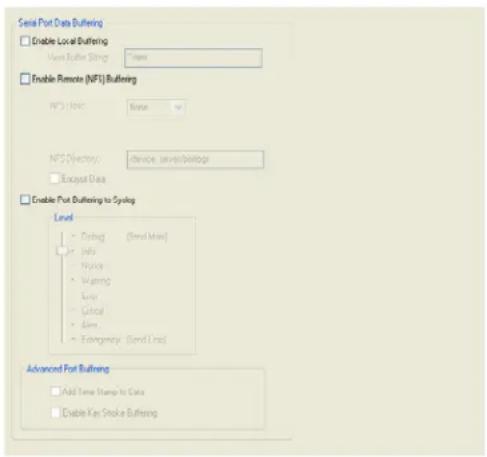
text_image
Serial Port Data Buffering Enable Local Buffering Main Buffer String: None Enable Remote (NFS) Buffering NFS Level: None NFS Directory: Device, server/brdots Excerpt Data Enable Port Buffering to Syslog Level • Debug (Send Max) • Info • Nfix • Wearing • Loss • Control • Alert • Exstringency (Send Line) Advanced Port Buffering • Add Time Stamp to Data • Enable Key Stroke BufferingConfigure the following parameters:
Enable Local Buffering
Enables/disables local port buffering on the IOLAN.
Default: Disabled
View Port Buffering The string used by a session connected to a serial port to display the port String buffer for that particular serial port.
Data Options: Up to an 8 character string. You can specify control (unprintable) codes by putting the decimal value in angle brackets <> (for example, Escape b is <027>b).
Default: \~view
| Enable Remote(NFS) Buffering | Enables/disables port buffering on a remote system. When you enable this option, you have the ability to save the buffered data to a file(s) (one file is created for each serial port) and/or send it to the Syslog host for viewing on the Syslog host's monitor.Default: Disabled |
| NFS Host | The NFS host that the IOLAN will send data to for itsRemote Port Bufferingfeature. The IOLAN will open a file on the NFS host for each serial port configured forConsole Management, and will send serial port data to be written to that file(s).Default: None |
| NFS Directory | The directory and/or subdirectories where theRemote Port Bufferingfileswill be created. For multiple IOLANs using the same NFS host, it is recommended that each IOLAN have its own unique directory to house the remote port log files.Default:/device_server/portlogs |
| Encrypt Data | Determines if the data sent to the NFS host is sent encrypted or in the clear across the LAN.NOTE: When NFS encryption is enabled, the Decoder utility software is required to be installed on the NFS host for decrypting the data to a readable format. The Decoder utility software can be found on the installation CD-ROM and on thewww.perle.comwebsite.Default: Disabled |
| Enable PortBuffering to Syslog | When enabled, buffered data is sent to the syslog host to be viewed on the host's monitor. Choose the event level that will be associated with the "port buffer data" in the syslog.Data Options: Emergency, Alert, Critical, Error, Warning, Notice, Info, Debug.Default Level: InfoDefault: Disabled |
| Add Time Stamp to Data | Enable/disable time stamping of the serial port buffer data.Default: Disabled |
| Enable Key Stroke Buffering | When enabled, key strokes that are sent from the network host to the serial device on the IOLAN's serial port are buffered.Default: Disabled |
Advanced
Advanced Serial Settings Tab
Overview
Advanced serial port settings apply to all serial ports.
Field Descriptions
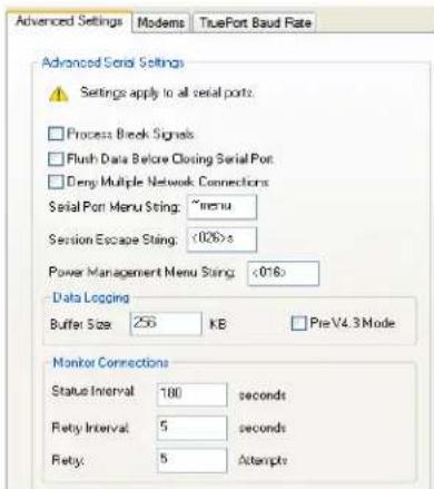
text_image
Advanced Settings Modems TruePort Baud Rate Advanced Serial Settings Settings apply to all serial ports: Process Break Signals Flush Data Before Closing Serial Port Deny Multiple Network Connections Serial Port Menu String: ~menu Session Escape String: <026> Power Management Menu String: <016> Data Logging Buffer Size 256 KB Pre V4.3 Mode Monitor Connections Status Interval: 180 seconds Fatty Interval: 5 seconds Fatty: 5 attemptsConfigure the following parameters:
Process Break Signals
Enables/disables proprietary inband SSH break signal processing, the Telnet break signal, and the out-of-band break signals for TruePort.
Default: Disabled
Flush Data Before Closing Serial Port
When enabled, deletes any pending outbound data when a port is closed. Default: Disabled
Deny Multiple Network Connections
Allows only one network connection at a time per a serial port. Application accessing a serial port device across a network with get a connection (socket) refused until:
- All data from previous connections on that serial port has drained
• There are no other connections - Up to a 1 second interconnection poll timer has expired
Enabling this feature automatically enables a TCP keepalive mechanism which is used to detect when a session has abnormally terminated. The keepalive is sent after 3 minutes of network connection idle time.
Applications using this feature need to be aware that there can be some considerable delay between a network disconnection and the port being available for the next connection attempt, allowing any data sent on prior connections to be transmitted out of the serial port. Application network retry logic needs to accommodate this feature.
Default: Disabled
| Data Logging Buffer Size | The minimum data buffer size for all models is 1 KB. The maximum data buffer size is 2000 KB for DS1/TS2/STS8D, all other models are 4000 KB. If the data buffer is filled, incoming serial data will overwrite the oldest data.Values: 1-2000 KB (DS1/TS1/STS8D) - Default 4 KBValues: 1-4000 KB (all other models) - Default 256 KBThe Data Logging buffer size is a valid option for the TruePort Profile and TCP Sockets Profile.Default: Disabled |
| Pre V4.3G Data Logging Mode | Enable the data logging feature previous to v4.3G firmware.Default: Disabled |
| Serial Port Menu String | When a user connects to the IOLAN through the network, the string used to access the Easy Port Access menu without disconnecting the network connection.Data Options: You can specify control (unprintable) codes by putting the decimal value in angle brackets <> (for example, ESC-b is <027>b).Default: ~menu |
| Session Escape String | When a user connects to the IOLAN through the network, the string is used to access the Reverse Session Menu.Data Options: You can specify control (unprintable) codes by putting the decimal value in angle brackets <> (for example, ESC-b is <027>b).Default: <026>s (Ctrl-z s) |
| Power Management Menu String | Users accessing the IOLAN through the network can enter the string to bring up the Power Bar Management menu.Data Options: You can specify control (unprintable) codes by putting the decimal value in angle brackets <> (for example, ESC-b is <027>b).Default: <016> (Ctrl-p) |
| Monitor Connection Interval Status | Specify how often, in seconds, the IOLAN will send a TCP Keepalive to services that support TCP Keepalive.Default: 180 seconds |
| Retry Interval | Sets the maximum time to wait for a response asfter sending a TCP keep alive message.Options: 1-32767Default: 5 seconds |
| Retry Attempts | The number of TCP keepalive retires before the connection is closed.Values: 1-32767Default: 5 |
Modems Tab
Overview
You need to configure a modem if there is a modem connected to the IOLAN. If your IOLAN model contains an internal modem or a PCI slot (SCS models) for a modem card, a permanent modem string called internal_modem or IOLAN modem, respectively, exists permanently in your configuration.
Functionality
Modems are usually configured for PPP/SLIP dial in/out connections, although some modems do support raw data communication. When you click on the Modems tab, you will see the following:
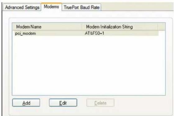
text_image
Advanced Settings Modems TruePort Baud Rate Modem Name Modem Initialization String pci_modem AT&FS0-1 Add Edit DeleteIf any modems have been configured, they will be displayed.
Adding/Editing a Modem
You can add new modems or edit existing modems through the following window:
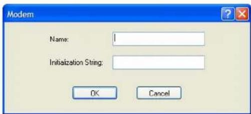
text_image
Modem Name: Initialization String: OK CancelConfigure the following parameters:
Name
The name of the modem.
Restrictions: Do not use spaces.
Initialization String The initialization string of the modem; see your modem's documentation.
TruePort Baud Rate Tab
Overview
The TruePort utility acts as a COM port redirector that allows applications to talk to serial devices across a network as though the serial devices were directly attached to the server. For IOLAN I/O models, you can also monitor and control I/O through the TruePort client.
Functionality
Since some older applications may not support the higher baud rates that the IOLAN is capable of achieving, the baud rate can be mapped to a different value on the IOLAN. Through TruePort, you can map the baud rate of the host COM port to a higher baud rate for the serial line that connects the serial device and the IOLAN. See TruePort for more information about the TruePort utility.
Field Definitions
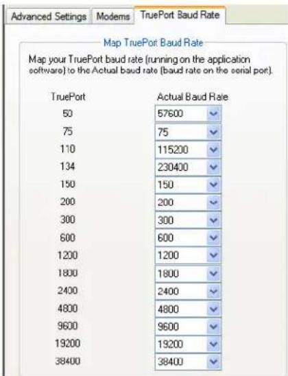
text_image
Advanced Settings Modems TruePort Baud Rate Map TruePort Baud Rate Map your TruePort baud rate (running on the application software) to the Actual baud rate (baud rate on the serial port). TruePort Actual Baud Rate 50 57600 75 75 110 115200 134 230400 150 150 200 200 300 300 600 600 1200 1200 1800 1800 2400 2400 4800 4800 9600 9600 19200 19200 38400 38400Configure the following parameter:
Actual Baud Rate The actual baud rate that runs between the IOLAN and the connected serial device.
Range: 50-230400, you can also specify a custom baud rate

natural_image
Abstract logo design with a stylized letter F inside a yellow circular frame (no text or symbols)Setting Jumpers
Introduction
The IOLAN contains jumpers that you might need to set before you configure it and put it into production. You can set the power out pin, pin 9, to a fixed 5V DC output or to the external adapter output; this can range from 9-30V DC (if an external adapter is shipped with the IOLAN, it has a 12V DC output); maximum output power is 1 (one) watt per a serial port. By default, the power out pin is set to no power. You can set the IOLAN line termination to on or off (this is off by default) if you are using EIA-422/485 (not applicable for I/O models).
1-Port IOLAN DB25 Male/Female
To change the settings, do the following:
- Unplug the IOLAN from the electrical outlet and disconnect everything from the box.
- Open the case by unscrewing the two side screws, one on each side, and lifting off the top of the case. You should see the following:
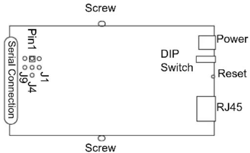
text_image
Screw Pin1 J1 J9 J4 Serial Connection DIP Switch Power Reset RJ45 Screw- To change the power pin out, locate J4. For the fixed 5V DC output, jumper pins 1 and 2. For the output to equal the external adapter input, jumper pins 2 and 3.
- To turn line termination on, locate and jumper J1 for Full Duplex Rx (422) or locate and jumper J9 for Half Duplex Rx/Tx (485).
- Close the IOLAN case by replacing the case lid and the two screws. You can now power it on with the new settings.
1-Port IOLAN RJ45
To change the settings, do the following:
-
Unplug the IOLAN from the electrical outlet and disconnect everything from the box.
-
Open the case by unscrewing the two side screws, one on each side, and lifting off the top of the case. You should see the following:
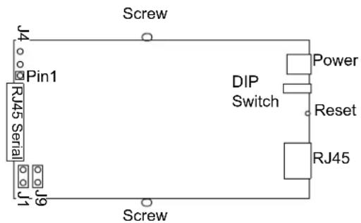
text_image
J4 Pin1 RJ45 Serial J9 Screw Screw DIP Switch Power Reset RJ45-
To change the power pin out, locate J4. For the fixed 5V DC output, jumper pins 1 and 2. For the output to equal the external adapter input, jumper pins 2 and 3.
-
To turn line termination on, locate and jumper J1 for Full Duplex Rx (422) or J9 for Half Duplex Rx/Tx (485).
-
Close the IOLAN case by replacing the case lid and the two screws. You can now power it on with the new settings.
1-Port IOLAN RJ45 P (Power Over Ethernet)
To change the settings, do the following:
-
Unplug the IOLAN from the electrical outlet and disconnect everything from the box.
-
Open the case by unscrewing the two side screws, one on each side, and lifting off the top of the case. You should see the following:
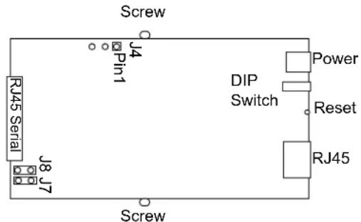
text_image
Screw J4 Pin1 RJ45 Serial J8 J7 Screw DIP Switch Power Reset RJ45-
To change the power pin out, locate J4. For the fixed 5V DC output, jumper pins 1 and 2. For the output to equal the external adapter input, jumper pins 2 and 3.
-
To turn line termination on, locate and jumper J7 for Full Duplex Rx or locate and jumper J8 for Half Duplex Rx/Tx.
-
Close the IOLAN case by replacing the case lid and the two screws. You can now power it on with the new settings.
1-Port IOLAN DB9
To change the settings, do the following:
-
Unplug the IOLAN from the electrical outlet and disconnect everything from the box.
-
Open the case by unscrewing the two side screws, one on each side, and lifting off the top of the case. You should see the following:
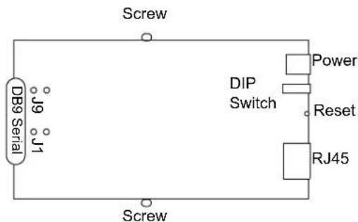
text_image
Screw DB9 Serial J9 J1 DIP Switch Power Reset RJ45 Screw-
To turn line termination on, locate and jumper J1 for Full Duplex Rx (422) or J9 for Half Duplex Rx/Tx (485).
-
Close the IOLAN case by replacing the case lid and the two screws. You can now power it on with the new settings.
2-Port IOLAN SDS1M (Modem)
To change the settings, do the following:
-
Unplug the IOLAN from the electrical outlet and disconnect everything from the box.
-
Open the case by unscrewing the two side screws, one on each side, and lifting off the top of the case. You should see the following:
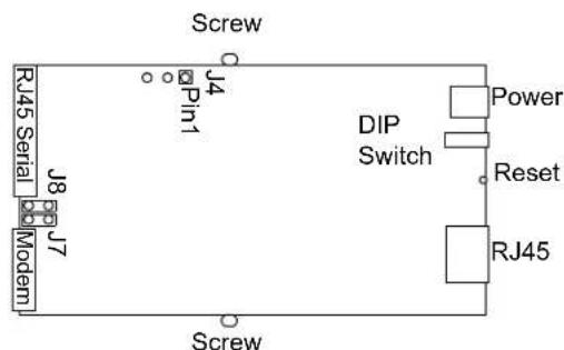
text_image
Screw RJ45 Serial J8 Pin1 J7 Modem1 DIP Switch Power Reset RJ45 Screw-
To change the power pin out, locate J4. For the fixed 5V DC output, jumper pins 1 and 2. For the output to equal the external adapter input, jumper pins 2 and 3.
-
To turn line termination on, locate and jumper J7 for Full Duplex Rx or locate and jumper J8 for Half Duplex Rx/Tx.
-
Close the IOLAN case by replacing the case lid and the two screws. You can now power it on with the new settings.
2-Port IOLAN
To change the settings, do the following:
- Unplug the IOLAN from the electrical outlet and disconnect everything from the box.
- Open the case by unscrewing the two side screws, one on each side, and lifting off the top of the case. You should see the following:
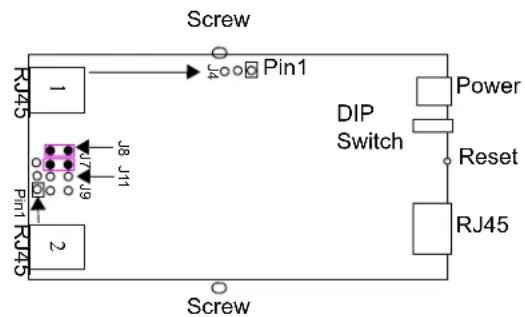
text_image
Screw Pin1 RJ45 1 J8 J11 Pin1 2 DIP Switch Power Reset RJ45 Screw- To change the power pin out, locate the set of three pins associated with the line you want to set (Line 1 is J4; Line 2 is the set the three pins just to the left of port 2). For the fixed 5V DC output, jumper pins 1 and 2. For the output to equal the external adapter input, jumper pins 2 and 3.
- To turn line termination on for Line 1, locate and jumper J7 for Full Duplex Rx or locate and jumper J8 for Half Duplex Rx/Tx. To turn line termination on for Line 2, locate and jumper J9 for Full Duplex Rx and locate and jumper J11 for Half Duplex Rx/Tx.
- Close the IOLAN case by replacing the case lid and the two screws. You can now power it on with the new settings.
2-Port IOLAN RJ45 P (Power Over Ethernet)
To change the settings, do the following:
- Unplug the IOLAN from the electrical outlet and disconnect everything from the box.
- Open the case by unscrewing the two side screws, one on each side, and lifting off the top of the case. You should see the following:
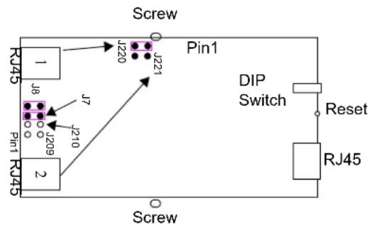
text_image
Screw Pin1 RJ45 1 J8 J7 J209 J220 J221 DIP Switch Reset RJ45 Pin1 RJ45 2 J710 Screw- For the fixed 5V DC output, locate and jumper J220 for Line 1 (as shown in the diagram) and/or jumper J221 for Line 2.
-
To turn line termination on for Line 1, locate and jumper J7 for Full Duplex Rx or locate and Jumper J8 for Half Duplex Rx/Tx. To turn line termination on for Line 2, locate and jumper J209 for Full Duplex Rx or locate and Jumper J210 for Half Duplex Rx/Tx.
-
Close the IOLAN case by replacing the case lid and the two screws. You can now power it on with the new settings.
Serial power in is not supported in the SDS2 PoE model.
4-Port Desktop IOLAN
To change the settings, do the following:
-
Unplug the IOLAN from the electrical outlet and disconnect everything from the box.
-
Open the case by unscrewing the two side screws, one on each side, and lifting off the top of the case. You should see the following:

text_image
Screw 1 J8 J4 J7 J11 J9 J5 2 J24 J22 J10 3 J25 J23 J6 DIP Switch The pin with the square represents Pin 1 ---> Power Reset RJ45 Screw- The following table describes how to jumper the pins for line termination, fixed 5V output, and for output equal to the external adapter input:
| Port # Line Termination 5V Output Input Volt Output | |
| 1 Jumper J7 for Full Duplex | J4, jumper pins 1 & 2 J4, jumper pins 2 & 3 |
| Jumper J8 for Half Duplex Rx/Tx | |
| 2 Jumper J9 for Full Duplex Rx | J5, jumper pins 1 & 2 J5, jumper pins 2 & 3 |
| Jumper J11 for Half Duplex Rx/Tx | |
| 3 Jumper J22 for Full Duplex Rx | J10, jumper pins 1 & 2 J10, jumper pins 2 & 3 |
| Jumper J24 for Half Duplex Rx/Tx | |
| 4 Jumper J23 for Full Duplex Rx | J6, jumper pins 1 & 2 J6, jumper pins 2 & 3 |
| Jumper J25 for Half Duplex Rx/Tx | |
- Close the IOLAN case by replacing the case lid and the two screws. You can now power it on with the new settings.
Digital I/O Module
IOLANs that have Digital I/O have an input/output jumper that must be set for each channel and must match the software configuration for each channel. Depending on the model, the placement of the digital I/O board can change, so the diagram below shows how to set jumper for any digital board. To change the settings, do the following:
- Detach the IOLAN from the electrical power source and disconnect everything from the box.
- Open the case by unscrewing the five side screws, two on each side plus the grounding screw, and lifting off the top of the case. You should see the following configuration for the digital I/O board:
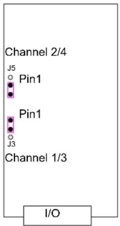
text_image
Channel 2/4 J5 Pin1 Pin1 J3 Channel 1/3 I/OJumper pins 1 and 2 for Input. Jumper pins 2 and 3 for Output.
- To turn line termination on, locate and jumper J8 for Half Duplex Rx/Tx.
- To configure either Channel 1 or Channel 3 (depending on how many Digital channels your I/O supports and following the mylar channel definitions) for Input, jumper J3 pin 1 and 2 (as shown); this is the default setting. To configure either Channel 2 or Channel 4 (depending on how many Digital channels your I/O supports and following the mylar channel definitions) for Output, jumper J5 pin 2 and 3 (as shown).
- Close the IOLAN case by replacing the case lid and the five screws. You can now power it on with the new settings.
Analog Input Module
IOLANs that have Analog Input have a voltage/current jumper that must be set for each channel and must match the software configuration for each channel. To change the settings, do the following:
-
Detach the IOLAN from the electrical power source and disconnect everything from the box.
-
Open the case by unscrewing the five side screws, two on each side plus the grounding screw, and lifting off the top of the case. You should see the following configuration for the analog input board:
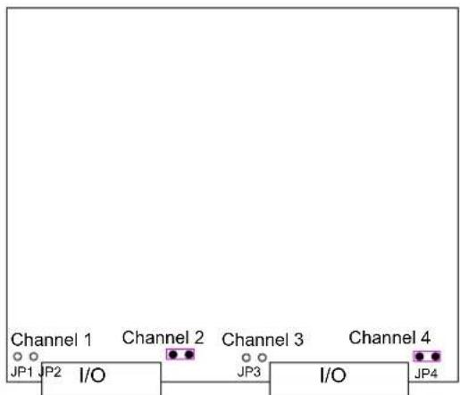
flowchart
graph LR
    JP1["JP1"] --> I0["I/O"]
    JP2["JP2"] --> I0
    I0 --> JP3["JP3"]
    JP3 --> I0
    JP4["JP4"] --> I0
    I0 --> JP4
    I0 --> J0["Channel 1"]
    I0 --> J1["Channel 2"]
    I0 --> J2["Channel 3"]
    I0 --> J3["Channel 4"]
-
To configure Channel 1 for Voltage, no jumper should be set (as shown); this is the default setting. To configure Channel 2 for Current, jumper both J2 pins (as shown).
-
Close the IOLAN case by replacing the case lid and the five screws. You can now power it on with the new settings.

natural_image
Abstract logo design featuring a stylized letter 'G' inside a yellow circular frame with star-like elements (no text or symbols)I/O Wiring Diagrams
Wiring I/O Diagrams
This section describes how to wire the various IOLAN I/O models.
Digital I/O
Make sure the Digital I/O jumpers support the software setting; see Digital I/O Module for jumper settings.
Digital Input Wet Contact
If you are using a wet contact for your Digital input, for channel D1 connect one wire to D1 and the other wire to GND. The power source is supplied by external sources.

text_image
D1 D2 GND COM VCC Power SourceDigital Input Dry Contact
If you are using a dry contact for your Digital input, for channel D1 connect one wire to D1 and the other wire to COM. The power source is supplied by the COM (common) connector.
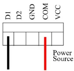
text_image
D1 D2 GND COM VCC Power SourceDigital Output Sink
For a Digital output sink (ground) configuration for channel D1, follow the diagram below.
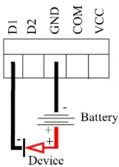
text_image
D1 D2 GND COM VCC Battery DeviceDigital Output Source
For a Digital output source (voltage) configuration for channel D1, follow the diagram below.
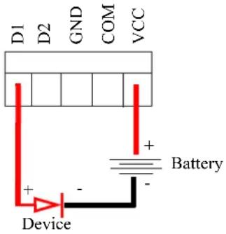
text_image
D1 D2 GND COM VCC + - Device BatteryAnalog Input
Make sure the Analog jumpers support the software setting; see Analog Input Module for jumper settings.
Current
To connect channel A1 with a 2-wire shielded cable, connect the positive wire to A1+, the negative wire to A1-, and optionally the shield to GND.

text_image
A1+ A1- A2+ A2- + -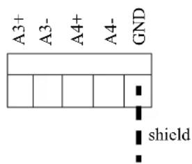
text_image
A3+ A3- A4+ A4- GND shieldIf you have the positive/negative wires reversed, the output will always read 0 (zero).
Voltage
To connect to Channel A1 with a 2-wire shielded cable, connect the positive wire to A1+, the negative wire to A1-, and optionally the shield to GND.

text_image
A1+ A1- A2+ A2- + -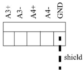
text_image
A3+ A3- A4+ A4- GND shieldIf you have the positive/negative wires reversed, the polarity of the voltage will be reversed.
Temperature Input
If you are using RTD sensors, a short detected status will be displayed if the wires are connected improperly. RTD or thermocouple sensors will display an open detection status when the circuit is broken.
Thermocouple
To connect to Channel A1 with a 2-wire cable, connect the positive wire to A1+ and the negative wire to A1-; you will not be using the A1s connection.
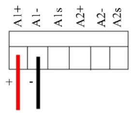
text_image
A1+ A1- A1s A2+ A2- A2s + -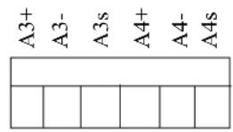
RTD 2-Wire
In a 2-wire RTD configuration, connect the excite wire to A1-, the return wire to A1+, and jumper the sense wire from A1s with a insulated wire going to A1+.
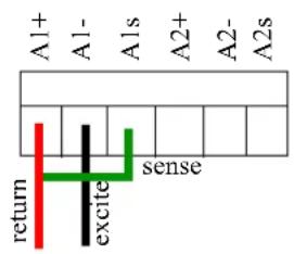
text_image
A1+ A1- A1s A2+ A2- A2s return excite sense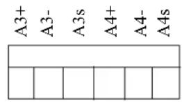
RTD 3-Wire
In a 3-wire RTD configuration, connect the return wire to A1+, the excite wire to A1-, and the sense wire to A1s.
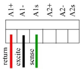
bar
| Category | Value | |---|---| | return | 0 | | excite | 0 | | sense | 0 | | A1+ | 0 | | A1- | 0 | | A1s | 0 | | A2+ | 0 | | A2- | 0 | | A2s | 0 |
RTD 4-Wire
In a 4-wire RTD configuration, connect the return wire to A1+, the excite wire to A1-, the sense wire to A1s, and leave the fourth wire disconnected.
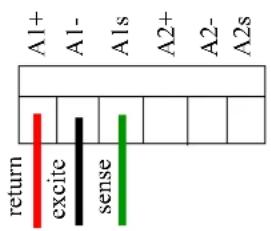
text_image
A1+ A1- A1s A2+ A2- A2s return excite sense
Relay Output
Normally Open Contact
To connect Relay channel RI for a circuit that is normally inactive, connect one wire to the COM (common) connector and one wire to the NO (normally open) connector.
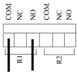
text_image
COM NC NO COM NC NO R1 R2Normally Closed Contact
To connect relay channel R1 for a circuit that is normally active, connect one wire to the COM (common) connector and one wire to the NC (normally closed) connector.
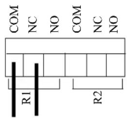
text_image
COM NC NO COM NC NO R1 R2
natural_image
Abstract logo with a black letter 'H' inside a yellow circular frame with star-like patterns (no text or symbols)Utilities
Introduction
This chapter provides information on the TruePort and Decoder utilities.
TruePort
TruePort is a com port redirector utility for the IOLAN. It can be run in two modes:
- TruePort Full mode—This mode allows complete device control and operates exactly like a directly connected serial port. It provides a complete COM port interface between the attached serial device and the network.
- TruePort Lite mode—This mode provides a simple raw data interface between the device and the network. Although the port will still operate as a COM port, control signals are ignored. In this mode, the serial communications parameters must be configured on the IOLAN.
You use TruePort when you want to connect extra terminals to a server using the IOLAN rather than a multi-port serial card. TruePort is especially useful when you want to improve data security, as you can enable an SSL/TLS connection between the TruePort host port and the IOLAN. When run on UNIX, TruePort allows you to print directly from a terminal to an attached printer (transparent printing). You can also remap the slow baud rate of your UNIX server to a faster baud rate, as shown below.
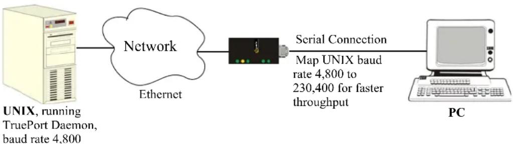
flowchart
graph LR
    A["UNIX, running TruePort Daemon, baud rate 4,800"] --> B["Network"]
    B --> C["Ethernet"]
    C --> D["PCI"]
    D --> E["Serial Connection Map UNIX baud rate 4,800 to 230,400 for faster throughput"]
Currently, TruePort is supported on Linux, Windows ^® , SCO ^® , Solaris ^® , and others. For a complete list of the supported operating systems, see the Perle website.
For more information, see the TruePort User Guide or the TruePort Installation and Configuration Guide for Windows ^® NT on the CD-ROM.
API I/O Access Over TruePort
You can access IOLAN I/O data through TruePort using the Perle API. The API uses the command/response format. See the ioapiotp.c sample program, found on the product CD-ROM, for an example implementation.
API Request Format
All data in the Request must be sent as a single write to the COM port. The API command takes the following format:
| Number of Bytes Value | |
| 1 Function Code (in hexadecimal): | |
| 01—Get read/write boolean register | |
| 03—Get read/write register | |
| 04—Get read only register | |
| 15—Set read/write boolean register (0x0F) | |
| 16—Set read/write register (0x10) | |
| 2 | Starting register number (seeA4/T4 Registers , A4D2/A4R2 Registers , orD4/D2R2 Registersfor this value). |
| 2 Number of registers to act on starting from the register defined in byte 2 above. | |
| n | Data for write. Some values must be read/written as a unit consisting of 2 consecutive registers. If the request is to write, the data to write follows the number of registers. If accessing registers consisting of 2 bytes or 4 bytes, the data is in big endian (network order) format. |
API Response Format
The API command takes the following response format:
| Number of Bytes Value | |
| 1 Function code of request if no error. Most significant bit will be set if an error occurred. | |
| 1 | Length of data in response if no error occurred. If an error occurred, the byte will contain the error code (see the Error Codes table below). |
| n Data response for request (the number of bytes is dependent on the number and type of registers requested). If the request returns 2 or 4 byte values, it will be in big endian (network order) format. If the request returns boolean values, the least significant bit (bit 0) represents the first value requested and bits 1 to 7 represents subsequent boolean values. If more than 8 boolean registers are requested, they are returned in successive bytes. | |
Error Codes
| Code Name Description | ||
| 01 | Illegal Function | The function code received in the query is not an allowable action for the server (or slave). |
| 02 | Illegal Data Address | The data address received in the query is not an allowable address for the server (or slave). |
| 03 | Illegal Data Value | A value contained in the query data field is not an allowable value for server (or slave). |
| 04 | Slave Device Failure | An unrecoverable error occurred while the server (or slave) was attempting to perform the requested action. |
Decoder
If you are using Port Buffering NFS Encryption, you need to run the Decoder utility to view the port buffering logs. See the Readme file to install the Decoder utility on any of the following operating systems:
- Windows ^® 2000 and greater platform
Note: The Windows/DOS platform restricts the converted readable file to an 8.3 filename limitation.
• DOS
- Solaris x86
• Solaris Spare 32-bit/64-bit
Linux x86 v2.4.x

natural_image
Abstract logo with a black vertical bar inside a yellow circular frame, surrounded by intersecting curved lines (no text or symbols)Accessories
Introduction
This chapter provides information about peripheral IOLAN options that can be ordered separately from the product. Contact your sales representative to find out how to order the products listed in this appendix.
Installing a Perle PCI Card
This sections describes how to install the Perle IOLAN modem card and the Perle PCI adapter card, used with a wireless WAN card, in your SCS rack mount model.
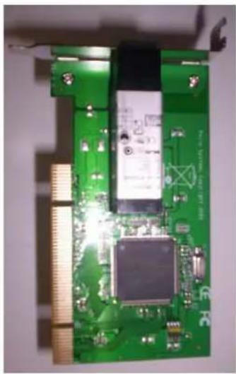
natural_image
Close-up of a green printed circuit board with visible components and connectors (no readable text or symbols)IOLAN Modem Card
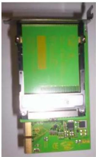
natural_image
Close-up of a green printed circuit board with visible traces and components (no text or symbols)PCI Adapter Card
The location and brackets are slightly different for the 32-port and 48-port SCS rack mount models, but the basic installation concept is the same. The PCI adapter card bracket is found on the serial side of the 8-port/16-port/32-port models and the LED side of the 48-port model.
Do not touch any of the components within the SCS IOLAN while performing the PCI adapter card installation.
- Unscrew the six screws on the top of the SCS IOLAN.

natural_image
Front view of a black network switch device with multiple Ethernet ports and indicator lights (no visible text or labels)- Unscrew the four screws along the bottom of the serial side of the SCS IOLAN. On the SCS 8-port/16-port/32-port models, this includes the screw that is at the bottom of the PCI face plate.

natural_image
Front view of a network switch device with multiple Ethernet ports and indicator lights (no visible text or labels)-
Slide the top of the IOLAN off of the chassis.
-
Carefully holding the bracket just behind the face plate, unscrew the two screws at the top of the 8-port/16-port/32-port removable face plate or the two side screws of the 48-port removable face plate of the piece you just took off.
32-port model

natural_image
Dark rectangular object with two small white circular spots on top (no text or symbols visible)48-port model

natural_image
Dark background with two small white dots at top corners (no text or symbols)The 8-port/16-port/32-port models are displayed below with the face plate and bracket taken apart.
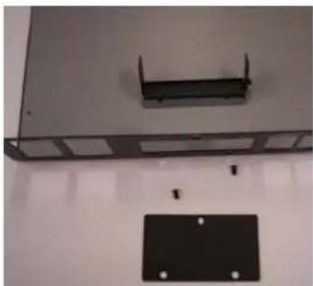
natural_image
Two electronic device components: a metal enclosure and a black rectangular base with mounting holes (no visible text or symbols)- Unscrew the screw in the bracket. The 8-port/16-port/32-port bracket is shown below.

natural_image
Black rectangular object with a small circular mark and handle, no visible text or symbols- Slide the PCI adapter card into the bracket.
32-port model
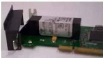
natural_image
Close-up of a green printed circuit board with a black plastic cover and a yellow tag, no visible text or symbols.48-port model
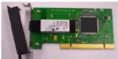
natural_image
Green PCI card with visible internal components and a black connector (no text or symbols)- The black bracket should then fit on the inside of the PCI adapter card bracket. Align the adapter card bracket and then insert the screw and tighten it to keep it firmly in place.
32-port model
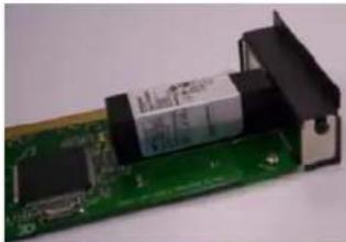
natural_image
Close-up of a green printed circuit board with a black plastic clip attached (no visible text or symbols)48-port model

natural_image
Close-up of a green printed circuit board with a black plastic component and a white battery, no visible text or symbols.You must attach the bracket to the PCI adapter card before you slide it into the PCI slot.
- If you are installing the PCI Adapter card, slide the wireless WAN card into the adapter card.
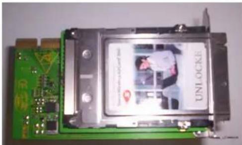
natural_image
Green printed circuit board with a black plastic cover and a 'UNLOCKE' label, no readable text or symbols on the main components.- Slide the PCI adapter card into the PCI slot.
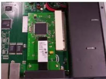
natural_image
Close-up of a green printed circuit board with visible components and connectors (no readable text or symbols)- You can now replace the top of the IOLAN chassis by aligning it and sliding it into the base. You can throw away the face plate, as you will not be needing it.
32-port model

natural_image
Close-up of a black electronic device casing with ports and indicator lights (no readable text or symbols)48-port model
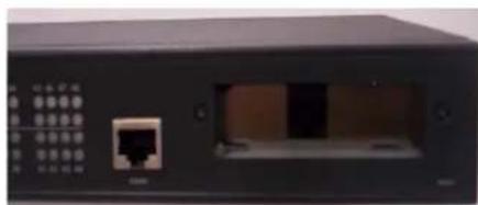
natural_image
Front view of a black network switch device with ports and indicator lights (no visible text or labels)- Replace all the screws on the top and the serial side of the IOLAN. If you installed a wireless WAN card, you can now attach the external antenna to the card.
Starter Kit (Adapters/Cable)
The IOLAN Starter Kit includes the following for all IOLAN models (except the medical unit models):
• RJ45F to DB25M DTE Crossover Adapter
• RJ45F to DB25M DCE Modem Adapter
• RJ45F to DB25F DTE Crossover Adapter
• RJ45F to DB9M DTE Crossover Adapter
• RJ45F to DB9F DTE Crossover Adapter
• Sun/Cisco RJ45M Connector Cable for Rack Mount Models
The adapters/cable can be purchased as a kit or individually.
RJ45F to DB25M DTE Crossover Adapter
The following diagram shows the IOLAN RJ45F-->DB25M DTE crossover adapter pinouts. This is model number DBA0011.
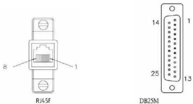
RJ45F DB25M DTE
(TxD) 43 (RxD)
(RxD) 52 (TxD)
(GND) 67 (GND)
(DTR) 8 6 (DSR) 8 (DCD)
(DSR) 3 20 (DTR)
(RTS) 25 (CTS)
(CTS) 74(RTS)
RJ45F to DB25M DCE Modem Adapter
The following diagram shows the IOLAN RJ45F→DB25M DCE modem adapter pinouts. This is model number DBA0013.
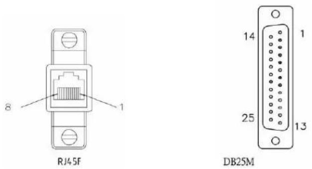
RJ45F DB25M
(TxD) 42 (RxD)
(RxD) 53 (TxD)
(GND) 67 (GND)
(DTR) 8 20 (DTR)
(DSR) 3 6 (DSR)
(DCD) 18 (DCD)
(RTS) 24 (RTS)
(CTS) 75 (CTS)
RJ45F to DB25F DTE Crossover Adapter
The following diagram shows the IOLAN RJ45→DB25F DTE crossover adapter pinouts. This is model number DBA0010.
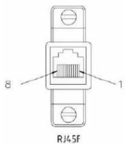
text_image
8 RJ45F 1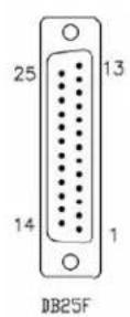
RJ45F DB25F
(TxD) 43(RxD)
(RxD) 52 (TxD)
(GND) 67 (GND)
(DTR) 86(DSR)
8 (DCD)
(DSR) 3 20 (DTR)
(RTS) 25 (CTS)
(CTS) 74(RTS)
RJ45F to DB9M DTE Crossover Adapter
The following diagram shows the IOLAN RJ45→DB9M crossover adapter pinouts. This is model number DBA0021.
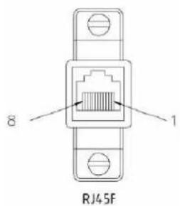
text_image
8 RJ45F 1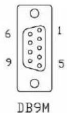
RJ45F DB9M
(TxD) 42 (RxD)
(RxD) 53 (TxD)
(GND) 65 (GND)
(DTR) 81(DCD) 6 (DSR)
(DSR) 34 (DTR)
(RTS) 28 (CTS)
(CTS) 7 7 (RTS)
RJ45F to DB9F DTE Crossover Adapter
The following diagram shows the IOLAN RJ45F→DB9F crossover adapter pinouts. This is model number DBA0020.
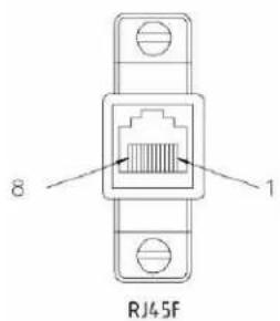
text_image
8 RJ45F 1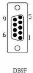
RJ45F DB9F
(TxD) 42(RxD)
(RxD) 53 (TxD)
(GND) 65 (GND)
(DTR) 81(DCD) 6 (DSR)
(DSR) 34 (DTR)
(RTS) 28 (CTS)
(CTS) 7 7 (RTS)
Sun/Cisco RJ45M Connector Cable for Rack Mount Models
This is a 3 meter RJ45M→RJ45M 8-wire Sun/Cisco modular cable. The following diagram shows how the IOLAN RJ45M cable is configured when connecting to the supplied Sun/Cisco RJ45 cable. This model number is CAB0030.
| IOLAN RJ45M | Sun/Cisco RJ45M |
| (RTS) 2 8 (CTS) | |
| (DSR) 3 2 (DTR) | |
| (TxD) 4 6 (RxD) | |
| (RxD) 5 3 (TxD) | |
| (GND) 6 4 (GND) | |
| (CTS) 7 1 (RTS) | |
| (DTR) 8 7 (DSR) |
SCS48C/SCS32C/SCS16C/SCS8C Starter Kit (Adapters/Cable)
The IOLAN Starter Kit includes the following for the SCS48C/SCS32C/SCS16C/SCS8C (Sun/Cisco) models:
• RJ45F to DB25M DTE Crossover Adapter
• RJ45F to DB25M DCE Modem Adapter
• RJ45F to DB25F DTE Crossover Adapter
• RJ45F to DB9M DTE Crossover Adapter
• RJ45F to DB9F DTE Crossover Adapter
• Sun/Cisco Roll-Over Adapter for Rack Mount Models
The adapters/cable can be purchased as a kit or individually.
RJ45F to DB25M DTE Crossover Adapter
The following diagram shows the IOLAN RJ45F→DB25M DTE crossover adapter pinouts. This is model number DBA0011C.
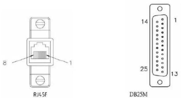
RJ45F DB25M DTE
(TxD) 3 3 (RxD)
(RxD) 62 (TxD)
(GND) 4 —— 7 (GND)
(GND) 5
(DTR) 26 (DSR) 8 (DCD)
(DSR) 7 20 (DTR)
(RTS) 15 (CTS)
(CTS) 84(RTS)
RJ45F to DB25M DCE Modem Adapter
The following diagram shows the IOLAN RJ45F→DB25M DCE modem adapter pinouts. This is model number DBA0013C.
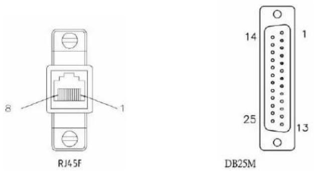
RJ45F DB25M
(TxD) 32 (TxD)
(RxD) 63 (RxD)
RJ45F to DB25F DTE Crossover Adapter
The following diagram shows the IOLAN RJ45→DB25F DTE crossover adapter pinouts. This is model number DBA0010C.
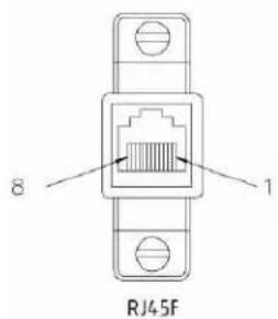
text_image
8 RJ45F 1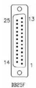
RJ45F DB25F
(TxD) 3 3 (RxD)
(RxD) 62 (TxD)
(GND) 4 —— 7 (GND)
(GND) 5
(DTR) 2 6 (DSR) 8 (DCD)
(DSR) 7 20 (DTR)
(RTS) 15 (CTS)
(CTS) 84 (RTS)
RJ45F to DB9M DTE Crossover Adapter
The following diagram shows the IOLAN RJ45→DB9M crossover adapter pinouts. This is model number DBA0021C.
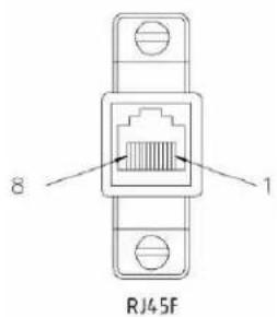
text_image
8 RJ45F 1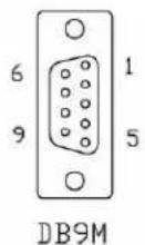
RJ45F DB9M
(TxD) 32 (RxD)
(RxD) 63 (TxD)
(GND) 4 —— 5 (GND)
(GND) 5
(DTR) 21 (DCD) 6 (DSR)
(DSR) 74 (DTR)
(RTS) 18 (CTS)
(CTS) 87 (RTS)
RJ45F to DB9F DTE Crossover Adapter
The following diagram shows the IOLAN RJ45F→DB9F crossover adapter pinouts. This is model number DBA0020C.
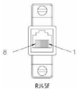
text_image
8 RJ45F 1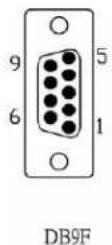
RJ45F DB9F
(TxD) 32(RxD)
(RxD) 63 (TxD)
(GND) 4 —— 5 (GND)
(GND) 5
(DTR) 21(DCD) 6 (DSR)
(DSR) 74(DTR)
(RTS) 18 (CTS)
(CTS) 87 (RTS)
Sun/Cisco Roll-Over Adapter for Rack Mount Models
This is a RJ45M→RJ45F Sun/Cisco adapter. This model number is DBA0031C.
| IOLAN RJ45F | Sun/Cisco RJ45M* |
| 1 | 8 |
| 2 | 7 |
| 3 | 6 |
| 4 | 5 |
| 5 | 4 |
| 6 | 3 |
| 7 | 2 |
| 8 | 1 |
*The Sun/Cisco RJ45M connector attaches to the Sun/Cisco Console port.
Introduction
This chapter provides information that can help resolve problems with the IOLAN.
Hardware Troubleshooting
The Power/Ready LED stays red after a boot (See Getting to Know Your IOLAN for the LED label on your IOLAN unit.):
If the IOLAN Power/Ready LED is red and stays red for over 10 seconds, you have a hardware problem that might require factory service. First, try the following:
- If the IOLAN is not in Console mode, do the following:
a. Set up a direct connection to the IOLAN; see Console/Serial Switch for information on this type of connection.
b. Power the IOLAN off.
c. Switch the Console dip switch to On.
d. Power the IOLAN on.
e. Read the messages on the console to determine if the problem can be fixed.
If there is a problem with the IOLAN firmware, you will need to reload the firmware, which can be found either on the CD-ROM that came with the IOLAN or on the Perle website, www.perle.com/downloads (when you access the webpage, select your specific IOLAN model).
- If the IOLAN is already in Console mode and the Power LED stays red, you need to make arrangements to return the IOLAN.
- In Console mode for desktop models or viewing the Console port in rack mount models, see if you need to reload the firmware, which can be found either on the CD-ROM that came with the IOLAN or on the Perle website, www.perle.com/downloads (when you access the webpage, select your specific IOLAN model).
- If the bootloader option does not appear when you reboot the IOLAN (to load new firmware), you need to make arrangements to return the IOLAN.
If you purchased the IOLAN less than 30 days before this problem appears, contact your distributor; otherwise, see the Perle web site (www.Perle.com) for factory service information.
No factory service can be performed on IOLANs that have not been registered.
The Power/Ready LED blinks red (See Communication Issues for the LED label on your IOLAN unit.):
- Good Boot: When the IOLAN cycles through a good boot, the LED blinks for several seconds and then stays a solid green.
- Non-critical Error Boot: When the IOLAN cycles through a boot and a non-critical error occurs, such as a bad port, the LED will blink red briefly before displaying a solid green. You should reboot the IOLAN while monitoring the Console port to view the error information.
- Critical Error Boot: When the IOLAN cycles through a boot and a critical error occurs, such as corrupted firmware, the LED continues to blink red. View the diagnostic information displayed on the terminal connected to the Console port for information on how to correct the problem.
- Fatal Error Boot: When the IOLAN cycles through a boot and a fatal error occurs, the LED stays a solid red).
Communication Issues
General communication checks and practices are as follows:
- Are your cables connected and correctly configured? If you are using EIA-232, see EIA-232 Cabling Diagrams to verify that your cables are correctly configured.
- Can you ping your host? If you can ping but packet loss is reported, ping another host/device on the same network. This will tell you whether the problem is specific to the host/device or general to the network.
- After entering or changing IP information for your IOLAN, reboot the IOLAN (does not apply when using BOOTP or DHCP). Once the IOLAN has rebooted, other network devices should be able to communicate with it (ping, telnet, etc.). Also, protocols such as ARP and proxy-ARP will work properly.
- Use the show routes command (command line only) or view the Routes statistics. Is there a route to the host?
- If the WebManager or DeviceManager cannot communicate with the IOLAN, verify that the Server Services HTTP and/or HTTPS are enabled for WebManager and DeviceManagerD is enabled for DeviceManager. If you are using only HTTPS, the connection URL must start with https://.
DeviceManager Problems
Error Message: 16 bit Windows Subsystem - C:\WINDOWS\SYSTEM32\AUTOEXEC.NT. The system file is not suitable for running MS-DOS and Microsoft Windows applications. Choose 'Close' to terminate the application.
The error message can be misleading, because it is displayed even if the AUTOEXEC .NT file is actually missing.
To verify whether you have the file, type %windir%/system32/ in the address bar of an Explorer window. If there is no AUTOEXEC.NT file proceed as follows:
- Browse to %windir%/repair/ (usually C:\WINDOWS\repair).
- Right-click and Copy the AUTOEXEC .NT file.
- Browse to %windir%/system32/ (usually C:\WINDOWS\System32).
- Right-click inside the window and Paste the file.
The error condition described here may also be the result of corruption of the AUTOEXEC . NT file, in which case the above procedure may be helpful to restore a valid file.
If the above procedure does not fix the DeviceManager installation problem, see http://support.microsoft.com/?kbid=324767 for the official Microsoft explanation.
Host Problems
Cannot access a host by name:
- If using DNS or if DNS is required, ensure a nameserver is configured on your IOLAN and is accessible (ping it).
- If not using DNS, verify that the host is configured in the Host Table. Check access to the host by pinging it using the host's IP address.
Cannot access a host on a local network, verify:
• The network address is correct.
- The subnet mask is set correctly and reflects the network configuration.
- The broadcast address is set correctly and reflects the network configuration.
Cannot access a host on a remote network:
- Use the show route command to verify that there is a route to the remote host. If no gateway is specified, verify that a default gateway is specified. Ping the default gateway to check if it is working.
- Consider the situation beyond the gateway; for example, are intermediate gateways and the remote host available? Also, check the messages returned by the ping command; for example, that a particular host or gateway is unreachable.
Gateways added into the gateway table are ignored by the IOLAN:
- Have you used BOOTP and entered a single static gateway in the bootptab file entry? If yes, the other gateways will be ignored.
Access to host lost after a few minutes.
- If the route to this host goes through routers, make sure those routers are all sending RIP packets across the networks.
RADIUS Authentication Problems
User is waiting up to 60 seconds before login is accepted or denied and Authentication is set to RADIUS. User has entered User Name and Password, and has pressed Enter.
- Check RADIUS configuration of primary and secondary authentication/accounting hosts specified, if you have retry and timeout values greater than the default, the IOLAN will be spending time trying each of these hosts and keeping the user waiting.
- Adjust RADIUS configuration: specify just one host, reduce Timeout and Retry values to the default or less than default.
You cannot progress beyond the login and password prompts when authentication is set to RADIUS:
- On the RADIUS host, check the secret (password), you should see it displayed in clear text in the RADIUS clients file. If you are unsure whether it is the same secret which you entered in the IOLAN, go to the IOLAN and re-enter a new secret.
- On the RADIUS host, verify that there is only one entry for a particular user; do not have multiple entries of the same user name (even if the passwords are different).
Login Problems
You cannot obtain a login on any of the serial ports
- Connect via the Admin port and check the settings of the front-mounted ports; they have probably been set to a profile that does support serial connections, such as the Console Management profile (in CLI or Menu, 'direct' or 'silent' telnet/rlogin). Try setting the serial port(s) to the Terminal profile (DSlogin in CLI or Menu).
You have lost or don't know your password (as Admin user).
- You must reset the IOLAN to its factory default settings using the Reset switch on the rear panel. There is no procedure to access the IOLAN without a password.
Problems with Terminals
The following section concerns problems with the appearance of data on your terminal screen.
The IOLAN logs me out after a few minutes:
- Check the Idle Timer value set for the user. The default setting for the Idle Timer for all users is 0 seconds (does not timeout).
Corrupt data.
- Check your line settings (baud rate, stop bits, etc.)
Missing data.
- Verify that the same type of flow control is set in both your terminal and on the IOLAN's port.
Error message not permitted on a dumb terminal after typing the CLI command screen.
- Set your Line to Termtype VT100, ANSI or WYSE60 (or other form of terminal emulation, if you have downloaded one). The default line type in the IOLAN is Dumb, which does not support the graphics characters necessary to view the text-based menus.
Screen corruption when using the text-based menu system.
- Verify that the terminal setup in the IOLAN matches your terminal.
- Verify that entries in the term file match your terminal setup.
- If using a PC/computer, verify that the type of terminal emulation selected in your application matches those supported by the IOLAN.
When using the function keys on your keyboard, nothing happens or your sessions keep swapping.
- Change your Hotkey Prefix character. The function keys on the keyboards of some terminals (like WYSE60) send character sequences which begin with ^a; unfortunately, ^a is also the default Hotkey Prefix, which you use to switch between sessions. A valid alternative would be ^b (hexadecimal=02). If you are the system administrator, you can change any user's Hotkey Prefix character.
When using a downloaded terminal definition, you are having problems using arrow keys.
- Use Ctrl-K, Ctrl-J, Ctrl-H and Ctrl-L for up, down, left and right respectively.
When switching from a session back to the text menus, both screen images are superimposed.
- Press ^r to redraw the screen.
INIT: Error in terminal file
- This error indicates that you have exceeded the 80 character limit for one or more of the terminal capabilities defined in the reported file.
INIT: Error on line n in terminal file
- You have omitted the = sign from the reported line.
Unknown IP Address
You have already configured the IOLAN and you do know your password, and have lost, misconfigured, or don't know the IP address of the IOLAN, so you cannot obtain a successful login.
- If the IOLAN resides within the local network segment, you can use DeviceManager to find the IOLAN.
- You can connect directly to the serial port of the IOLAN, as explained in Using a Direct Serial Connection to Specify an IP Address.
DHCP/BOOTP Problems
Messages: host name too long or filename too long.
- The IOLAN can only accept host names of 14 characters or file names of 64 characters, so verify that you are not attempting to pass a string that is longer than those maximums.
DHCP or BOOTP have been set up to configure my IOLAN, but does not seem to have done anything.
- Check that the server DHCP/BOOTP service is set to on, if not set it to on and reboot.
- Check that your BOOTP server is configured for your IOLAN or that your DHCP server has an active lease pool (scope) with at least 1 free IP address.
You observe TFTP errors when the IOLAN boots, for example:
TFTP: File not found : filename
TFTP: Timed out
This has a number of causes, including:
- The file names you specified to DHCP/BOOTP do not exist or are in the wrong place.
- The server for any of the downloadable files in your bootfile has no TFTP server running.
- Verify that lease data in your DHCP server manager is correct.
- Reset or restart the DHCP server.
Callback Problems
User Callback is On, and a number is configured for the line, but the IOLAN is not calling the user back:
- Verify that the phone number is entered under the user (not the line).
- Verify that the callback Phone Number is valid.
- Verify that the modem at the user's end is set to 'auto-answer'.
Language Problems
In a customized language, the text strings appear in the wrong place in the Menu, CLI, or WebManager.
- Check the original ASCII text file you used to translate to your customised language. The sequence of the line much match exactly (be aware that comments don't affect line sequence, but can affect the actual line that the strings appear on). So, if you strip out all comments, if the original file says line 1000 should be string none, then line 1000 (stripped of comments) should be the translated version of none.
Modem Problems
The IOLAN is not initializing the modem.
- Check your Line Service is set to SLIP or PPP. If your line service is set to any other type, the IOLAN will not initialize a modem. You will need to configure the modem manually.
PPP Problems
The link fails on start-up when there are remote IP addresses set for both a user (Framed IP value) and a line (Remote IP address).
- Check the IP address set for the user; this is used in preference to the IP address set for a line. If there is a problem with the user's IP address, negotiation will fail; the IOLAN will not use the line's IP address as an alternative.
The link fails on start-up and security (either PAP or CHAP) is enabled on the line.
- Check the remote client/device has the same setting; that is, PAP if the IOLAN is using PAP. The IOLAN does not perform negotiation with the remote end over PAP or CHAP.
At the remote end, the client software locks up when security (CHAP) is enabled on the line.
- Disable CHAP re-challenge parameter (challenge_interval) in the IOLAN. Some PPP client software does not work when receiving CHAP re-challenges.
PPP is not running successfully over your 485 half-duplex environment.
- PPP is incompatible with half-duplex; it must be run over a full-duplex environment.
PPP will not authenticate with CHAP and TACACS+.
- Disable MS_CHAP on the client side.
Printing Problems
The print job fails to print on the device attached to the serial port.
- On the line where the printer is attached, set Line Service to Printer. Print jobs will not print when the line service is set incorrectly.
When using RCP, the network host receives a rejection message from the IOLAN. The result is that the print job does not take place.
- Print using LPD
or
- Modify the printer interface scripts on the network host to overcome this weakness of RCP. The modification will force the network host to continue trying to send the print job when the IOLAN's printer port is busy.
Long Reboot Cycle
Rebooting the IOLAN takes a long time.
If you are not using DHCP/BOOTP, disable this within the Server Services; otherwise, the IOLAN waits to timeout for a request to DHCP/BOOTP.
SSL/TLS
If you are experiencing problems obtaining a successful SSL/TLS connection, you can set your Syslog Level to Notice and view the syslog for the following messages:
Line not SSL enabled. Abort connection when a user who is configured for Service SSL_RAW tries to login on the serial port.
The user has been configured for an SSL_RAW connection, but the line has not been configured to enable SSL. To resolve this, either enable the line for SSL or change the user's Service to TCP_CLEAR if SSL is not wanted.
Could not obtain peer's certificate.
- User has selected a cipher key exchange of ADH (anonymous Diffie-Hellman) and enabled Peer verification. ADH does not use certificates so they will not be sent in an SSL/TLS handshake. Disable Peer Verification or change to a cipher suite that uses certificates.
- User has selected Peer Verification on the configured SSL/TLS server and has not configured a certificate for the client. Either disable peer verification on the SSL/TLS server or configure a certificate for the SSL/TLS client.
SSL\_accept failed on the SSL/TLS server device.
- The device has failed to accept an SSL/TLS connection on top of a TCP connection that has just been established. This could indicate that the peer from which TruePort is trying to accept a connection from is not configured for SSL/TLS. Verify that the peer has been configured for an SSL/TLS client connection.
Certificate did not match configuration
- The message is displayed when Validate Peer Certificate has been enabled, but the configured Validation Criteria does not match the corresponding data in the certificate received from the peer. The data configured must match exactly to the data in the certificate. The data is also case sensitive.
unknown protocol message when trying to make an SSL/TLS connection
- This will be displayed when both sides of the TCP connection are configured as SSL/TLS clients. Change one of the end points to act as an SSL/TLS server.
- One of the endpoints is not configured for SSL/TLS. Make sure both endpoints are configured for SSL/TLS, verify that one is a client and the other is a server.
tlsv1 alert handshake failure or sslv3 alert handshake failure
- The remote site has an SSL/TLS error and is sending this message with an alert message. Look at the error messages on the remote end and fix the problem indicated.
I/O Models
An I/O Digital or Relay controlled motor is starting/stopping
- Digital and Relay channels have automatically resetting fuses, meaning that if the circuit gets overloaded and the fuse blows, it will automatically reset when the circuit cools down.
An A4R2 model is starting/stopping
- The A4R2 model can run at 55 degrees Celsius ambient temperature when the input voltage is 22VDC or below. If the input voltage exceeds 22VDC, the maximum ambient temperature will drop into the range of 45-50 degrees Celsius to run successfully.
IPv6 Issues
You are not seeing the IPv6 address value when you attempt to connect to the IOLAN.
Many Windows ^® based systems have IPv6 support already enabled, however, if you need to install IPv6 then follow the procedure below.
To install IPv6 support do the following:
- In Control Panel, double-click the Network Connections icon.
- Double-click the Local Area Connection entry.
- In the Local Area Connection Status window, click the Properties button on the General tab.
- In the Local Area Connections window, click the Install button on the General tab.
- In the Select Network Component Type window, select Protocol and click the Add button.
- In the Select Network Protocol window, select Microsoft TCP/IP version 6 and click the OK button.
Contacting Technical Support
Making a Technical Support Query
Who To Contact
Note: Perle offers free technical support to Perle Authorized Distributors and Registered Perle Resellers.
If you bought your product from a registered Perle supplier, you must contact their Technical Support department; they are qualified to deal with your problem.
Have Your Product Information Ready
When you make a technical support enquiry please have the following information ready:
| Item Write Details Here | |
| Product Name | |
| Problem Description | |
| Your Name | |
| Company Name and Address | |
| Country | |
| Phone Number | |
| Fax Number | |
| Email Address | |
Making a support query via the Perle web page
If you have an internet connection, please send details of your problem to Technical Support using the email links provided on the Perle web site in the Support/Services area.
Click here to access our website at the following URL:
http://www.perlc.com
Repair Procedure
Before sending the IOLAN for repair, you must contact your Perle supplier. If, however, you bought your product directly from Perle you can contact directly.
Customers who are in Europe, Africa or Middle East can submit repair details via a website form.
This form is on the Perle website, www.perle.com, in the Support/Services area.
Click here to access our web site at the following URL:
http://www.perle.com/support_services/rma_form.asp
Feedback on this Manual
If you have any comments or suggestions for improving this manual please email Perle using the following address:
Email: ptac@perle.com
Please include the title, part number and date of the manual (you can find these on the title page at the front of this manual).

natural_image
Abstract logo design featuring a stylized letter 'K' inside a yellow circular frame with abstract star-like patterns (no text or symbols)Data Logging
Introduction
This appendix provides additional information about the Data Logging Feature
Trueport Profile
The following features are not compatible when using the Data Logging feature.
- Allow Multiple Hosts to connect
- Connect to Multiple Hosts
• Monitor DSR or DCD
• Signals high when not under Trueport client control - Message of the day
- Session timeout
TCP Socket Profile
The following features are not compatible when using the Data Logging feature.
- Allow Multiple Hosts to connect
- Connect to Multiple Hosts
• Monitor DSR or DCD - Permit connections in both directions
- Authenticate user
- Message of the day
- Session timeout
Introduction
This appendix provides additional information about the Modbus Remapping feature.
Modbus Remapping Feature
The Modbus remapping feature allows a TCP Modbus Master to poll a Modbus slave device and have the IOLAN translate the UID to a different UID for the slave device. The Master UID has to be unique on the IOLAN. The Slave UID must be unique on each serial port. The translate rules are controlled by a file downloaded to the IOLAN.
The following procedure will allow you to use the Modbus remapping feature:
Create a configuration file
- The file must be called "modbus_remap"
• One translate rule per line - The fields on a line are separated by a comma
Line format for one UID is:
port, master_uid, slave_uid
- port: is the IOLAN port number that the slave is connected to
- master_uid: is the UID that the TCP Modbus Master uses
- slave_uid: is the UID that the Modbus slave uses
Line format for UID ranges is:
port, master_start-master_end, slave_start-slave_end
- port: is the IOLAN port number that the slave is connected to
- master_start: is the first master UID in the range
- master_end: is the last master UID in the range
- slave_start: is the first slave UID in the range
- slave_end: is the last slave UID in the range
Configuring the Modbus UID Translation Feature
-
On the serial port Modbus Gateway, configure Modbus slave. Configuration parameters such as "UID range" and UID Address Mode will be ignored in this mode of operation
-
Down load the "modbus_remap" file that you created to the IOLAN using:
● Device Manager: use "tools-advanced-custom files" dialog "download other file"
Web Manager: use "administration-custom files" page "other file"
- CLI: use the command "netload customapp-file" command

natural_image
Abstract logo with a black letter 'M' inside a yellow circular frame with star-like patterns (no text or symbols)Symmetric Key File
Symmetric Key File
This section defines the layout of the NTP/SNTP Symmetric Key file that must be downloaded to the IOLAN in order to use NTP/SNTP server authentication feature. Each line of the NTP/SNTP symmetric key file consists of three fields: a key ID in the range 1 to 65,534, inclusive, a key type and a message digest key consisting of a printable ASCII string equal to or less than 20 characters or a 40 character hex digit string.
| key ID key type | message digest key | ||
| 1 | MD5 | CeR {+’9LRTY:a0=P?GOA | ascii string |
| 2 | MD5 | POE) + ’9KRMY:P0-PZOQ | ascii string |
| 3 | MD5 | E) + ’9KRRTS {+’9LRTpp | ascii string |
| 4 MD5 ECcE) + ’9KRDSRuurQPiw ascii string | |||
| 5 | SHA1 | 0e9e44502940294fa788aafaac34ccb126347d34 | hex digit string |
| 6 | SHA1 | f4c9c4454c9c4450294faccb126309ff4ccb1200 | hex digit string |
| 7 | SHA1 | c9c44502949c4450294ccb12634c9c447d3489 | hex digit string |
| 8 | SHA1 | 40294fa7894faccb126502944fac4e9e788aafaa | hex digit string |
Note: Note:1-10 key ID entries are allowed in this NTP/SNTP key file. Both MD5 and SHA1 are supported. Key ID 0 is excluded.

natural_image
Abstract logo design with a large black letter 'N' inside a yellow circular frame with star-like patterns (no text or symbols)Troubleshooting the USB Modem
Modem not connecting to the network.
This appendix provides some helpful troubleshooting tips for getting your USB modem to connect to your wireless network.
In most cases, the IOLAN will be able to detect, initialize and operate the USB modem automatically. The pre-requisites for successfully connecting your USB modem to your service provider's network are an installed Perle USB option card that is configured with the service provider's APN, phone number (normally *99#), optional username, password and PIN#/SIM lock code. Refer to Configuring a USB Modem.
After configuring the USB option card and USB modem settings, you must save the configuration and either reboot the IOLAN or kill the PCI line service (the last serial line service) for the settings to take effect. Successful connection to the wireless network can take up to 2 minutes. Most USB modems have LEDs indicating the connection status. A solid green or blue LED on your USB modem usually indicate a successful wireless connection. If the connection is not established after this time, please try the following:
1) Connect a terminal to the IOLAN using the console port and cable.
2) Login as admin
3) Issue the CLI command "usb show modem"
Depending on the various stages of trying to connect to the wireless network, you may see the following responses on your terminal. While the responses are mostly self-explanatory, the instructions below will suggest an action to take.
Output:
"USB modem feature is not supported on this hardware."
Action:
This feature is only valid on the IOLAN SCS models. Acquire IOLAN with option card slot and Perle USB option card.
Output:
"USB option card was not configured. Please select, configure and save the configuration for the USB option card and retry this command."
Action:
The usb option card and modem has not been configured. See Configuring a USB Modem
Output:
"No USB modem device detected. Please connect a USB modem to one
of the USB ports."
Action:
The software is not detecting a USB modem in the USB port. If one is inserted, please make sure that it is properly seated in the USB connector.
Output:
Manufacturer: manufacturer name
Product: product name
Vendor id: id
Stor. Prod Id: id
"USB modem detected and appears to be in storage mode."
Action:
None. This is displayed prior to initializing the USB modem. Wait a couple of seconds and issue this command again.
Output:
Manufacturer: manufacturer name
Product: product name
Vendor id: id
Stor. Prod Id: id
"Attempting to flip USB modem into modem mode."
Action:
None. The IOLAN is attempting to initialize the USB modem. Wait a minute and issue this command again.
Output:
Manufacturer: manufacturer name
Product: product name
Vendor id: id
Stor. Prod Id: id
In database?: Yes
"Attempting to flip USB modem into modem mode using USB mode switch configuration"
Action:
None. The IOLAN is attempting to initialize the USB modem. Wait a minute and issue this command again.
Output:
Manufacturer: manufacturer name
Product: product name
Vendor id: id
Stor. Prod Id: id
In database?: Yes
"Failed to initialize USB modem. Please try another USB modem device or contact Perle customer support with the device information above."
Action:
Try a different USB modem or search the internet linux community for possible updates to the usb_modeswitch configuration file for that vendor and product id. The USB modem may also be defective. Contact Perle support if there is no information on the internet pertaining to your USB modem. When searching the internet look for "usb_modeswitch vvvv:pppp" (vvvv is the vendor Id and pppp is the product Id from output above).
Output:
Manufacturer: manufacturer name
Product: product name
Vendor id: id
Stor. Prod Id: id
In database?: No
"Failed to initialize USB modem. Device configuration not found in our list of supported USB modems. Please try another USB modem device or contact Perle customer support with the device information above.
Action:
The information for this USB modem is not in our database. This could be due to the fact that this is a new model introduced after this version of software was issued. Try a different USB modem or search the internet linux community for a usb_modeswitch configuration file for that vendor and product id. Contact Perle support if there is no information on the internet pertaining to your USB modem. When searching the internet look for "usb_modeswitch vvvv:pppp" (vvvv is the vendor Id and pppp is the product Id from output above).
Output:
Manufacturer: manufacturer name
Product: product name
Vendor id: id
Modem Prod Id: id
"USB modem appears to be functioning normally. If connection problems persist, please review your USB modem configuration (APN, PIN #, PHONE #)."
Action:
As far as the driver can tell, the USB modem is functioning correctly. At this point, if you are not able to establish a connection with the network, the source of the problem could be the usb modem configuration. Check your configuration parameters and ensure it matches the information given to you by the network provider. See Configuring a USB Modem
Output:
Manufacturer: manufacturer name
Product: product name
Vendor id: id
Modem Prod Id: id
"USB modem appears to be functioning normally. If connection problems persist, please review your USB modem configuration (APN, PIN #, PHONE #)."
Action:
As far as the driver can tell, the USB modem is functioning correctly. If there is no wireless network connectivity, verify the APN, phone number and optional PIN#, user and password settings. Each service provider's network will have different requirements. See Configuring a USB Modem.
If this does not resolve the problem, use the Vendor id and product id to search the linux community for any problems with this particular device. If the recommendation is to use a device name override, use the "usb create modem-file devname ttyUSBn" (n = 1 to 4) to create the override option. Please remember to save your changes and either reset the PCI option line service or reboot the IOLAN, in order for the changes to take effect.
USB Modem Support and Custom Options
While we strive to include support for as wide a range of USB modems as possible, our support for USB modems is currently limited to the Communication Device Class Abstract Control Model interface (dev/ttyACMx device node), and the USB Serial Converter support for generic GSM and CDMA modems interface (dev/ttyUSBx device node). The IOLAN attempts to initialize the USB modem assuming the CDC-ACM type device, and after 30 seconds and multiple retries, it will try to initialize using the USB serial converter generic GSM/CDMA method. This latter method, requires a USB communication utility called "usb_modeswitch" that has a database of USB modems of this class. Should you have a USB modem that is not in our database, but is available by way of the linux internet community, please follow instruction below on how to download the file to the IOLAN. or contact Perle support for assistance.
There are also USB modems that require that a different device node be used other than the default /dev/ttyUSB0 device nodes. If after validating your USB modem configuration, you still do not have wireless connectivity, you may need to search through the Linux community using your USB modem's vendor id and product id, to determine if an override for the device node is required. The "usb modem status" command will output the information you need to do the search for connectivity issues in the linux community. To override the default device name, please use the following command:
usb create modem-file devname ttyUSBn (where n is an interface number between 1 - 4)
Should you find it necessary to remove the devname override, please use the "usb delete modem-file" command. This command will also remove any custom, downloaded usb_modem and modeswitch files (see next section).
Downloading Custom USB Modem Configuration Files
If you have a usb_modeswitch file which you have found for your USB modem and this modem is not currently in the IOLAN database, you can download the file as follows;
1) Connect a terminal to the IOLAN using the console port and cable.
2) Login as admin
3) Issue the following CLI command;
netload customapp-file <ip_address> <filename>
    ip_address is the address of your tftp server
    filename is the usb_modeswitch file full path and name
This will transfer the usb_modeswitch file from your TFTP server to the IOLAN. The file name is in the format "vvvv:pppp" where;
vvvv = Vendor ID
pppp = Storage Product ID
At this point, you can either re-boot the IOLAN or kill the PCI port to re-try the USB modem.

natural_image
Abstract yellow circular logo with interlocking curved lines (no text or symbols)Glossary
| This chapter provides definitions for Device Server terms. | |
| BOOTP (BOOTstrap Protocol) | An Internet protocol that enables a diskless workstation to discover its own IP address, the IP address of a BOOTP server on the network, and a file to be loaded into memory to boot the machine. This enables the workstation to boot without requiring a hard or floppy disk drive. |
| Callback | A security feature where the Device Server calls back the User at a predetermined number defined in the User's account. |
| CHAP (Challenge Handshake Authentication Protocol) | Standard authentication protocol for PPP connections. It provides a higher level of security than PAP and should be used whenever possible. see PAP |
| Community (SNMP) | An SNMP community is the group that devices and management stations running SNMP belong to. It helps define where information is sent. |
| DHCP (Dynamic Host Configuration Protocol) | A TCP/IP protocol that provides static and dynamic address allocation and management. |
| Direct Connection | Connections that bypass the Device Server enabling the user to log straight into a specific host. A direct connection is recommended where a user logging in to the Device Server is not required. |
| Ethernet | A high-speed (10Mbps,100Mbps) cable technology that connects devices to a LAN, using one or more sets of communication protocols. |
| Fixed Callback | A method where there is a specific number defined to callback a user. |
| Local Authentication | Uses the user ID and password stored within the Device Server User database. |
| LPD | Line Printer Daemon. A printer protocol that uses TCP/IP to establish connections between printers and workstations on a network. The technology was developed originally for BSD UNIX and has since become the de facto cross-platform printing protocol. |
| Modem Initialization String | A series of commands sent to the modem by a communications program at start up. These commands tell a modem how to set itself up in order to communicate easily with another modem. |
| MOTD | Message of the day. This is defined by a file whose contents display when users log into the Device Server. |
| Multicast | The broadcasting of messages to a specified group of workstations on a LAN, WAN, or internet. |
| NAK (Negative Acknowledgment) | A communication control character sent by the receiving destination indicating that the last message was not received correctly. |
| PAP (Password Authentication Protocol) | Standard authentication protocol for PPP connections. see CHAP |
| RADIUS (Remote Authentication Dial In Users Services) | An open standard network security server that communicates with the PAP protocol. |
| Reverse Connection | Connections that originate from a host that go directly to a serial device through the Device Server. |
| RIP (Routing Information Protocol) | A protocol that allows gateways and hosts to exchange information about various routes to different networks. |
| Roaming Callback | A method where the client supplies the number for callback when they dial in. |
| RPC | Remote Procedure Call. A type of protocol that allows a program on one computer to execute a program on a server computer. |
| Silent Connection | Silent connections are the same as direct connections except that they are permanently established. The host login prompt is displayed on the screen. Logging out redisplays this prompt. Silent connections, unlike direct connections, however, make permanent use of pseudo tty resources and therefore consume host resources even when not in use. |
| SNMP (Simple Network Management Protocol) | A protocol for managing network devices. |
| Subnet/Prefix Bits | Identifies the device's IP address, which portion constitutes the network address and which portion constitutes the host address. |

natural_image
Abstract yellow circular logo with interlocking curved lines (no text or symbols)Index
A
admin
default password 81
lost password 270
analog
calibrating 262
API
I/O commands 217,439
TruePort 216
ARP-Ping, setting an IP address 84
authentication, general 137
B
binary configuration file 95
BOOTP
parameters 71
setting an IP address 83
C
cabling, EIA-232 323
calibrating
analog 262
temperature 263
certificates
LDAP CA list 175
SSH, OpenSSH 175
SSL 175
CLI
IOLAN+ interface 67
configuration files
formats 95
connecting to the Device Server
console mode 42
serial mode 42
setting IP address 59
console mode 42
custom factory default configuration 261
D
DB25
pinouts
female 316
male 315
power in pin
female 317
male 316
DB9 male pinouts 321, 322
DC power requirements 29
Decoder utility 440
default admin password 81
definitions 473
Device Server models 53
DeviceManager
overview 61
setting an IP address 81
DHCP
parameters 71
setting an IP address 83
direct connect
setting an IP address 82
E
EasyPort Web 90
email notification events 232, 334
F
factory default configuration
custom 261
original 262
factory defaults, resetting to 269
H
Host 289
host-based printing 277
Host-to Host 289
HTTP Tunnels 285
|
installing
IOLAN modem card 441
rack mount 44
interface, IOLAN+ 74
I/O
Modbus 210
UDP 206
I/O SNMP traps 221
IOLAN+ interface 74
CLI 67
Menu 68
IOLAN+, supported models 74
IPsec 157
IPv6, setting an IP address 84
J
jumpers
line termination 426
power out 426
setting 426
K
keys
HTTPS 175
SSH 175
L
L2TP/IPsec 163
language
translating 267
upgrading firmware 267
LDAP
parameters 143
line termination, setting jumper 426
LPD printing 276
M
medical unit
description 40, 54
installing firmware 79
power supply 29
powering up 44
Menu
conventions 69
IOLAN+ 74
Menu IOLAN+ interface 68
MIB 72
Modbus
configuration overview 271
gateway settings 272
I/O access 210
line settings 273
TruePort 215
mode
console 42
serial 42
models, Device Server 53
modem card 441
modem parameters 424
N
NFS
Decoder utility 440
port buffering 419
NIS parameters 147
0
online help, using 26
OpenSSH 175
P
parameters
BOOTP/DHCP 71
LDAP 143
modems 424
NIS 147
port buffering 420
RADIUS 140
SecurID 146
SSH server 148
TACACS+ 145
password
admin default 81
IOLAN+ admin 74
lost 270
PCI slot 441
pin, power in
DB25 female 317
DB25 male 316
serial RJ45 318
pinouts
DB25 female 316
DB25 male 315
DB9 male 321, 322
RJ45 ethernet 322
RJ45 MDC serial 321
RJ45 SCS48C serial 319
RJ45 serial 318, 320, 467
port buffering 419
Decoder utility
Decoder utility 420
local 419
parameters 420
remote 420
power in pin
DB25 female 317
DB25 male 316
serial RJ45 318
power out, setting jumper 426
printers 276
printing
host-based 277
LPD 276
RCP 277
product repair 463
R
rack mount
description 39, 41
installing 44
RADIUS
parameters 140
supported RADIUS parameters 301
RCP printing 277
resetting to factory defaults 269
RIP
overview 116
RJ45
ethernet pinouts 322
MDC serial pinouts 321
SCS48C serial pinouts 319
serial pinouts 318, 320, 467
RJ45 serial power in pin 318
S
SecurID parameters 146
Serial 285
serial mode 42
Serial-to Host 287, 289, 292
Serial-to Serial 285
services
line
printer 276
signal I/O 390
UDP 360
vmodem 385
sessions 134
setting an IP address
ARP-Ping 84
BOOTP/DHCP 83
DeviceManager 81
direct connect 82
IPv6 84
signal I/O
general 390
SNMP
I/O traps 221
support MIBs 72
using 72
SSH server parameters 148
SSL certificate 175
supported models
IOLAN+ 74
T
TACACS+ parameters 145
technical support
contacting 462
online 462
product information 462
product repair 463
via the internet 462
temperature
calibrating 263
terminal definitions
creating 268
downloading 268
text configuration file 95
TruePort
API 216
Modbus 215
TruePort utility 347, 438
Tunnel Relay 292
U
UDP
configuring 360
UDP, I/O 206
user sessions 134
utility
Decoder 440
TruePort 347, 438
V
virtual modem 385
vmodem
overview 385
VNP
IPsec 157
VPN
exceptions 164
L2TP/IPsec 163
W
WebManager
overview 64