
UTC-520 - Screen Advantech - Free user manual and instructions
Find the device manual for free UTC-520 Advantech in PDF.


| Product Type | Industrial Touchscreen Monitor/Panel PC |
| Brand | Advantech |
| Model | UTC-520 |
| Display Size | 21.5 inches |
| Display Type | TFT LCD with LED Backlight |
| Resolution | 1920 x 1080 (Full HD) |
| Brightness | 300 cd/m² |
| Touchscreen | Projected Capacitive (PCT), Multi-touch |
| Dimensions (W x H x D) | 531 x 334 x 60 mm (20.9 x 13.15 x 2.36 in) |
| Weight | 7.5 kg (16.53 lbs) |
| Power Supply | 24V DC Input |
| Protection Rating | IP65 (Front Panel) |
| Operating Temperature | 0°C to 50°C (32°F to 122°F) |
| Mounting | VESA 100 x 100 mm, Panel Mount |
| Front Panel Material | Aluminum Alloy with Glass |
| Maintenance | Clean with soft damp cloth; avoid abrasives or solvents |
| Safety | Designed to meet CE, FCC, and UL standards |
| Spare Parts | Power supply, touch screen digitizer, interface cables |
| Reparability | Modular design; replaceable components |
| General Information | Fanless, rugged industrial display for HMI applications |
Frequently Asked Questions - UTC-520 Advantech
User questions about UTC-520 Advantech
0 question about this device. Answer the ones you know or ask your own.
Ask a new question about this device
Download the instructions for your Screen in PDF format for free! Find your manual UTC-520 - Advantech and take your electronic device back in hand. On this page are published all the documents necessary for the use of your device. UTC-520 by Advantech.
USER MANUAL UTC-520 Advantech
natural_image
Illustration of various electronic circuit boards on orange background (no text or symbols)UTC-510/515/520/532/542
10.1"/15.6"/21.5"/32"/42.5" Ubiquitous Touch Computer
Copyright
The documentation and the software included with this product are copyrighted 2020 by Advantech Co., Ltd. All rights are reserved. Advantech Co., Ltd. reserves the right to improve the products described in this manual at any time without notice. No part of this manual may be reproduced, copied, translated, or transmitted in any form or by any means without the prior written permission of Advantech Co., Ltd. The information provided in this manual is intended to be accurate and reliable. However, Advantech Co., Ltd. assumes no responsibility for its use, nor for any infringements of the rights of third parties that may result from its use.
Acknowledgements
Award is a trademark of Award Software International, Inc.
AMD is a trademark of Advanced Micro Devices.
Corning Gorilla is a trademark of Corning Inc.
Intel, Atom, Celeron, and Core are trademarks of Intel Corp.
IBM, PC/AT, PS/2 and VGA are trademarks of International Business Machines Corporation.
Microsoft Windows is a registered trademark of Microsoft Corp.
RTL is a trademark of Realtek Semiconductor Co., Ltd.
All other product names or trademarks are properties of their respective owners.
For more information about this or other Advantech products, please visit our website at http://www.advantech.com
For technical support and service, please visit our support website at
http://support.advantech.com
This manual is applicable for UTC-510/515/520/532/542.
Part No. 2008050014 Edition 5
Printed in Taiwan April 2020
Declaration of Conformity
FCC Class A
Note! This equipment has been tested and found to comply with the limits for a

Class A digital device, pursuant to Part 15 of the FCC Rules. These limits are designed to provide reasonable protection against harmful interference when the equipment is operated in a commercial environment. This equipment generates, uses, and can radiate radio frequency energy and, if not installed and used in accordance with the instruction manual, may cause harmful interference to radio communications. Operation of this equipment in a residential area is likely to cause harmful interference, in such cases users will be required to correct the interference at their own expense.
Warning!
Any modifications to this device that are not approved by the relevant standards authority may void the authority granted to the user by the FCC to operate this equipment.

Packing List
Before installing the UTC system, check that the following materials have been included in the shipment:
UTC-510/515/520/532/542 unit
■ Accessories for UTC-510/515/520
- DC 12V/5A 60W adaptor (UTC-515, UTC-520 A, B SKU)
- DC 12V/3A 36W adaptor (UTC-510)
- DC 12V/7A 84W adaptor (UTC-520 C/D/E SKU)
– SATA cable (not applicable for UTC-510)
– Packet of screws (not applicable for UTC-510)
■ Accessories for UTC-532
- SATA cable
- Packet of screws
- Antenna
If any of these items are missing or damaged, contact your distributor or sales representative immediately.
Technical Support and Assistance
- Visit the Advantech website at http://support.advantech.com to obtain the latest product information.
- Contact your distributor, sales representative, or Advantech's customer service center for technical support if you need additional assistance. Please have the following information ready before calling:
– Product name and serial number
– Description of your peripheral attachments
– Description of your software (operating system, version, application software, etc.)
– A complete description of the problem
– The exact wording of any error messages
Warnings
Warning!
Batteries are at risk of exploding if incorrectly installed. Replace only with the same or equivalent type recommended by the manufacturer. Dispose of used batteries according to the manufacturer's instructions.

Warning!

■ Input voltage rated 12V/3A (UTC-510)
■ Input voltage rated 12V/5A (UTC-515/520A/B/D)
■ Input voltage rated 12V/7A (UTC-520 C/D/E SKU)
Input voltage rated 100 \~ 240 VAC 50/60 Hz for UTC-532/542
■ Use a 3V/195mA lithium battery
- Packing: The unit should be carried with both hands and handled with care.
- Maintenance: Use only approved products or a dry applicator to clean and maintain the surfaces.
- CompactFlash: Turn off the system power before inserting or removing the CompactFlash storage card.
Contact information
Manufacturer
Advantech Co., Ltd.
No.1, Alley 20, Lane 26, Rueiguang Road Neihu District, Taipei, Taiwan 114, R.O.C.
TEL: (02) 2792-7818
EU Distributor
Advantech Europe GmbH Kolberger Straße 7 D-40599 Düsseldorf, Germany
Tel: 49-211-97477350
Fax: 49-211-97477300
Safety Instructions
- Read these safety instructions carefully.
- Retain this user manual for future reference.
- Disconnect the equipment from all AC outlets before cleaning. Use only a damp cloth for cleaning. Do not use liquid or spray detergents.
- For pluggable equipment, the power outlet socket must be located near the equipment and easily accessible.
- Protect the equipment from humidity.
- Place the equipment on a reliable surface during installation. Dropping or letting the equipment fall may cause damage.
- The openings of the enclosure are for air convection. Protect the equipment from overheating. Do not cover the openings.
- Ensure that the voltage is correct before connecting the equipment to a power outlet.
- Position the power cord away from high-traffic areas. Do not place anything over the power cord.
- All cautions and warnings on the equipment should be noted.
- If unused for a long time, disconnect the equipment from the power source to avoid damage from transient overvoltage.
- Never pour liquid into an opening. This may cause fire or electrical shock.
- Never open the equipment. For safety reasons, the equipment should be opened only by qualified service personnel.
- If one of the following occurs, have the equipment checked by authorized service personnel:
■ The power cord or plug is damaged.
- Liquid has penetrated the equipment.
■ The equipment has been exposed to moisture.
The equipment is malfunctioning or does not operate according to the user manual.
■ The equipment has been dropped and damaged.
■ The equipment shows obvious signs of breakage.
-
Do not store the equipment in an environment with a room temperature of below -20 °C (-4 °F) or above 60 °C (140 °F) as this may cause damage. The equipment should be stored in a controlled environment.
-
Batteries are at risk of exploding if incorrectly installed. Replace only with the same or equivalent type as recommended by the manufacturer. Discard used batteries according to the manufacturer's instructions.
-
Use only the recommended mounting apparatus to avoid damage caused by falling.
-
In accordance with the IEC 704-1:1982 specifications, the sound pressure level at the operator position does not exceed 70 dB (A).
DISCLAIMER: These instructions are provided according to IEC 704-1 standards. Advantech disclaims all responsibility for the accuracy of any statements contained herein.
Warning! Because of the risk of electric shock, do not remove the equipment
cover during operation or when connected to a power outlet.

Caution! To avoid short circuits and otherwise damaging the device, do not allow fluids to come in contact with the device. If fluids are accidentally spilled on the equipment, remove the affected unit from service as soon as possible and contact service personnel to verify that personal safety is not compromised. If the computer clock is unable to maintain accurate time or the BIOS configuration resets to default settings, check the battery.

Caution! Do not replace the battery yourself. Contact a qualified technician or your retailer. The computer is equipped with a battery-powered real-time clock circuit. There is a danger of explosion if the battery is incorrectly replaced. Replace only with same or equivalent type as recommended by the manufacturer. Discard used batteries according to the manufacturer's instructions.

Contents
Chapter 1 General Information ....1
1.1 Introduction 2
1.2 Specifications 2
1.2.1 UTC-510 2
1.2.2 UTC-510(PoE)....4
1.2.3 UTC-515 A/B/C 5
1.2.4 UTC-515D/E/F 6
1.2.5 UTC-515G....8
1.2.6 UTC-520A/B/C 9
1.2.7 UTC-520D/E/F 10
1.2.8 UTC-520G.... 12
1.2.9 UTC-532A/C 13
1.2.10 UTC-532E/F/G 14
1.2.11 UTC-542D/F/G 16
1.3 Dimensions 17
1.3.1 UTC-510 17
1.3.2 UTC-515 18
1.3.3 UTC-520 19
1.3.4 UTC-532 20
1.3.5 UTC-542 21
Chapter 2 System Setup....23
2.1 Quick Tour....24
2.1.1 Front View 24
2.1.2 Rear View 25
2.1.3 Side View 25
2.2 I/O Ports 26
2.2.1 UTC-510 26
2.2.2 UTC-510(PoE) 26
2.2.3 UTC-515 27
2.2.4 UTC-520 27
2.2.5 UTC-532 28
2.2.6 UTC-542 28
2.3 Setup Procedures 29
2.3.1 System Power On 29
2.3.2 BIOS Setup 29
2.3.3 System Software Installation.... 29
2.3.4 Driver Installation 29
Chapter 3 Upgrades and Installation....31
3.1 Introduction 32
3.2 Installing a 2.5" SATA HDD....32
3.3 Installing a CFAST Card (A/B Models Only) 33
3.4 Installing a Memory Module 33
3.5 Installing a Wireless LAN Card (Optional).... 34
3.6 Installing Peripherals (Optional) 35
3.6.1 UTC-510/510(PoE) 35
3.6.2 UTC-515/520/532 36
3.7 Panel Mount Installation for UTC-510 36
3.8 Installing a DRAM Module for UTC-510.... 37
3.8.1 UTC-510 37
3.8.2 UTC-510(PoE) 37
3.9 Installing an SSD Module for UTC-510.... 38
3.9.1 UTC-510 38
3.9.2 UTC-510(PoE) 38
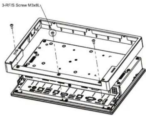
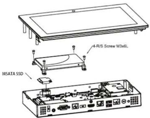
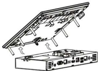
3.10 Installing an mSATA SSD Module for UTC-510 39
3.10.1 UTC-510 39
3.10.2 UTC-510(PoE) 39
3.11 Installing a Wi-Fi Module for UTC-510 40
3.11.1 UTC-510 40
3.11.2 UTC-510(PoE) 40
Appendix A Installation Accessories...... 41
A.1 Introduction 42
A.2 Wall Mount 43
A.3 Floor Stand 45
Appendix B UTC Peripherals 47
B.1 UTC-P01 (Camera Module) 48
B.1.1 Specifications.... 48
B.1.2 Packing List 48
B.1.3 Ordering Information 48
B.2 UTC-P02 (MSR) 49
B.2.1 Specifications.... 49
B.2.2 Packing List 49
B.2.3 Ordering Information.... 49
B.3 UTC-P03 (RFID Reader) 50
B.3.1 Specifications.... 50
B.3.2 Packing List 50
B.3.3 Ordering Information....51
B.4 UTC-P06 (Smart Card Reader) 52
B.4.1 Specifications.... 52
B.4.2 Packing List 52
B.4.3 Ordering Information....52
B.5 UTC-P07 (Barcode Reader) 53
B.5.1 Specifications.... 53
B.5.2 Packing List 54
B.5.3 Ordering Information.... 54
B.6 UTC-P21 (4-in-1 Module) 55
B.6.1 Specifications.... 55
B.6.2 Packing List 55
B.6.3 Ordering Information 55
B.7 UTC-510P-R01E 56
B.7.1 Packing List 56
B.7.2 Ordering Information.... 57
B.8 UTC-510P-S01E 58
B.8.1 Packing List 58
B.8.2 Ordering Information.... 58
B.9 UTC-510P-B 59
B.9.1 Packing List 60
B.9.2 Ordering Information....60
B.10 UTC-510P-M01E 61
B.10.1 Packing List 61
B.10.2 Ordering Information....61
Appendix C Touchscreen Options 63
C.1 Touchscreen Options....64
Chapter 1
General Information
1.1 Introduction
Advantech's UTC-500 series products are 10.1", 15.6", 21.5", 32", and 42.5" fanless, low-power, all-in-one touch panel computers suitable for use as control room computing devices, production line industrial digital signage, showroom interactive signage, self-service kiosks, and public service terminals that support diverse digital retail, hospitality, healthcare, education, entertainment, and information processing applications. Featuring a protective enclosure, advanced touchscreen technology, wireless capabilities, and multiple I/O, the high-performance UTC-500 series devices can also be integrated with a wide range of optional peripherals and accessories according to specific application requirements.
1.2 Specifications
1.2.1 UTC-510
| System | CPU | Intel® AtomTM E3825 (UTC-510D) | Intel® Celeron® J1900 (UTC-510D) | Intel® Celeron® N3350 (UTC-510G) | Intel® Pentium® N4200 (UTC-510G) |
| Base Frequency | 1.33 GHz (dual-core) | 2 GHz (quad-core) | 1.10 GHz (dual-core) | 1.10 GHz (dual-core) | |
| Cache L2 cache | 1 MB L2 cache 2 | MB L2 cache 2 MB | B L2 cache 2 MB | ||
| Memory | 1 x 204-pin SODIMM DDR3L 1066 MHz, up to 8 GB | 1 x 204-pin SODIMM DDR3L 1333 MHz, up to 8 GB | 1 x 204-pin SODIMM DDR3L 1866 MHz, up to 8 GB | ||
| HDD 1 x 2.5 internal SATA HDD bay | |||||
| Network (LAN) | 1 x Gigabit Ethernet port (with Wake-on-LAN support) | ||||
| I/O | 2 x RS-232 COM (COM1 RS-422/485 supported)1 x USB 2.0/1 x USB 3.0/2 x USB 2.0 (optional)1 x Gigabit Ethernet (RJ-45)1 x VGA1 x Audio Line-Out, 1 x Mic-In | 2 x RS-232 COM (COM1 RS-422/485 supported)2 x USB 3.0/2 x USB 2.0 (optional)1 x Gigabit Ethernet (RJ-45)1 x VGA1 x Audio Line-Out, 1 x Mic-In | |||
| Stereo Speaker | 1 x 2W | ||||
| Bus Expansion | 1 x Half-size mini PCIe1 x Half-size mSATA | 1 x Full-size mini PCIe1 x Half-size mSATA | |||
| Mount Options | VESA 75 x 75 mm | ||||
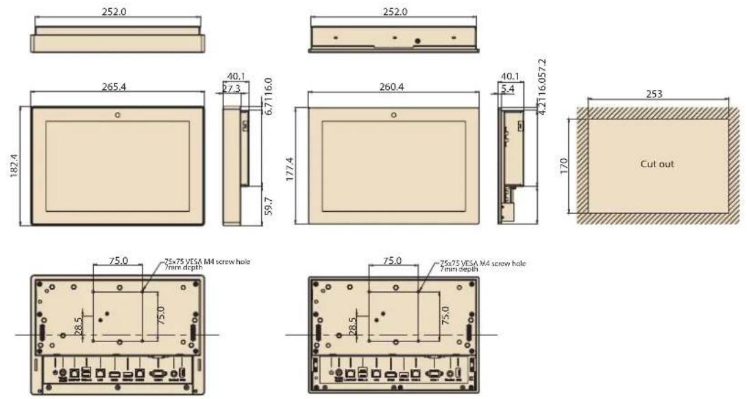
| Dimensions (W x H x D) | 265.4 x 182.4 x 39.55 mm (10.44 x 7.18 x 1.55 in) | ||||
| Weight 1.80 kg | (3.97 lb) | ||||
| OS Support | WES7P 32/64bitWES7E 32 bitWindows Pro Embedded 7 Pro 32/64 bitWE8S 32 bitWindows Embedded 8.1 Industry Pro 64 bitWindows 10 IoT Enterprise 64 bitLinux Ubuntu 16.04Android 4.4 | Windows 10 IoT Enterprise Linux Ubuntu 16.04Android 6.0 | |||
| Environmental | Front Panel Protection | IP65 compliant | ||
| Operating Temperature | 0 ~ 40 °C (32 ~ 104 °F) | 0 ~ 35 °C (32 ~ 95 °F) | 0 ~ 45°C (32 ~ 113°F) | |
| Relative Humidity | 10 ~ 95% @ 40 °C non-condensing | |||
| Vibration 1 Grms | ||||
| Shock 5G peak | acceleration (11 msec. duration) | |||
| Certification CE, FCC, CB, UL, CCC, BSMI | ||||
| Power Supply | Input Rating 12 | V/3 A (36W ITE adapter) | ||
| Power Consumption | Typical 10W Max. 20W | |||
| LCD Panel | Size/Type 10.1" TFT LCD with LED backlight | |||
| Max. Resolution | 1280 x 800 | |||
| Max. Color 16.7M | ||||
| Pixel Pitch 169 | 5 x 169.5 um | |||
| Brightness | 350 cd/m2 | |||
| Viewing Angle | 170°/170° | |||
| Camera 5 megapixel (optional) | ||||
| Touch-screen (PE/GE) | Type Glass panel with projected capacitive touch | |||
| Light Transmission | 80% ± 5% / 90% | |||
| Controller | USB interface | |||
1.2.2 UTC-510(PoE)
| System | CPU | Intel® Celeron® N2807 (UTC-510D) | Intel® Celeron® J1900 (UTC-510D) |
| Base Frequency 1 | 58 GHz (dual-core) | 2 GHz (quad-core) | |
| Cache L2 cache 1 | MB | L2 cache 2 MB | |
| Memory | 1 x SODIMM DDR3L 1333 MHz, up to 8 GB | 1 x SODIMM DDR3L 1333 MHz, up to 8 GB | |
| HDD 1 x 2.5 internal SATA HDD bay | |||
| Network (LAN) 2 x Gigabit Ethernet ports (with Wake-on-LAN support) | |||
| I/O | 2 x RS-232 COM (COM2 support for RS-422/485 optional)3 x USB 2.0/1 x USB 3.0/1 x USB 2.0 (optional)2 x Gigabit Ethernet ports (1 with PoE)1 x Headphone with mic | ||
| Stereo Speaker 2 x 2W | |||
| Bus Expansion | 1 Full-size mini PCIe/mSATA1 Half-size mini PCIe | ||
| Mount Options VESA 75 x 75 mm | |||
| Dimensions (W x H x D) | 265.4 x 182.4 x 39.55 mm (10.44 x 7.18 x 1.55 in) | ||
| Weight 1.80 kg (3.97 lb) | |||
| OS Support | Windows Embedded 7/8, Windows 10 IoT Enterprise, Linux Ubuntu 14.04, Android 4.4.2 | ||
| Environmental | Operating Temperature | 0 ~ 45 °C (32 ~ 113 °F) 0 ~ 40 °C (32 ~ 104 °F) | |
| Relative Humidity | 10 ~ 95% @ 40 °C non-condensing | ||
| Vibration 1 Grms | |||
| Shock 5G peak acceleration (11 msec. duration) | |||
| Certification | CE, FCC, CB, UL, CCC, BSMI | ||
| Front Panel Protection | IP65 compliant | ||
| Power Supply | Power over Ethernet | IEEE 802.3at/30W | |
| Input Rating | 12 V/3 A ~ 24 V/1.5 A, 36W ITE adapter (optional) | ||
| Power Consumption | Typical 10WMax. 20W | ||
| LCD Panel | Size/Type | 10.1" TFT LCD with LED backlight | |
| Max. Resolution | 1280 x 800 | ||
| Max. Color | 16.7M | ||
| Pixel Pitch | 169.5 x 169.5 um | ||
| Brightness | 350 cd/m2 | ||
| Viewing Angle | 170°/170° | ||
| Camera | 5 megapixel (optional) | ||
| Touchscreen (PE/GE) | Type Glass panel with projected capacitive touch | ||
| Light Transmission | 80% ± 5% / 90% | ||
| Controller | USB interface | ||
1.2.3 UTC-515 A/B/C
| System | CPU | AMD® G-Series T40E dual-core 1.0 GHZ (UTC-515A) | Intel® AtomTM D2550 dual-core 1.8 GHz (UTC-515B) | Intel® CoreTM i3-3217UE 1.6 GHz (UTC-515C) Can be equipped with Intel® CoreTM i7-3517UE 1.7 GHz upon request |
| Chipset T40E + | A50M | Intel ® AtomTM D2550 + Intel ® NM10 | Intel® QM77 | |
| Cache L2 cache | 512 KB L2 cache 1 MB | L2 cache 1 MB (L3 cache 3 MB) | ||
| Memory | 1 x SODIMM DDR3 1066 MHz, up to 4 GB | 1 x SODIMM DDR3 1066 MHz, up to 4 GB | 1 x SODIMM DDR3/ DDR3L 1333/1600 MHz, up to 8 GB | |
| HDD 1 x 2.5 internal SATA HDD bay | ||||
| Network (LAN) | 2 x Gigabit Ethernet ports (with Wake-on-LAN support) | |||
| I/O | 3 x RS-232 COM (RS-422/485 optional)4 x USB 2.02 x Gigabit Ethernet (RJ-45)1 x VGA/HDMI1 x Audio Line-Out1 x Mic-In | 3 x RS-232 COM (RS-422/485 optional)4 x USB 2.02 x Gigabit Ethernet (RJ-45)1 x VGA/HDMI1 x Audio Line-Out1 x Mic-In | 2 x RS-232 COM (RS-422/485 optional)2 x USB 2.0, 2 x USB 3.02 x Gigabit Ethernet (RJ-45)1 x VGA/HDMI1 x Audio Line-Out1 x Mic-In | |
| Stereo Speaker | 2 x 1W | |||
| Bus Expansion | 1 x Full-size mini PCIe/mSATA | |||
| Mount Options | VESA 100 x 100 mm | |||
| Dimensions (W x H x D) | 389.81 x 240.12 x 45.20 mm (15.34 x 9.45 x 1.77 in) | |||
| Weight 4.85 kg | (10.67 lb) | |||
| OS Support | Windows XP/XPE, Windows Embedded 7/8 | Windows Embed- ded 7 (32 bit) | Windows Embedded 7/8, Windows 10 IoT Enterprise | |
| Environmental | Operating Temperature | 0 ~ 40 °C (32 ~ 104 °F) | ||
| Relative Humidity | 10 ~ 95% @ 40 °C non-condensing | |||
| Vibration 0.5 Grms | ||||
| Shock | 5G peak acceleration (11 msec. duration) | |||
| EMC/Safety | CE, FCC, CB, UL, CCC, BSMI | |||
| Front Panel Protection | IP65/NEMA4 compliant | |||
| Power Supply | Input Rating | 12 V/5 A (60W ITE adapter) | 12 V/5 A (60W ITE adapter) | |
| Power Consumption | Typical 32W Max. 40W | Typical 40W Max. 50W | ||
| LCD Panel | Size/Type 15.6" TFT LCD with LED backlight | |
| Max.Resolution | 1366 x 768 (FHD 1920 x 1080 optional) | |
| Max. Color 16.7M | ||
| Pixel Pitch 252 | x 252 um | |
| Brightness | 400 cd/m2 | |
| Viewing Angle | 170°/160° | |
| Touchscreen(PE/RE/GE) | Type Glass panel with projected capacitive/5-wire analog resistive touch | |
| LightTransmission | 90% ± 2% / 80% ± 5% / 90% | |
| Controller USB | interface | |
1.2.4 UTC-515D/E/F
| System | CPU | Intel® Celeron® J1900 (UTC-515D) | Intel® CoreTM i5-4300U (UTC-515E) Can be equipped with Intel® CoreTM i3-4010U/Celeron® 2980U upon request | Intel® CoreTM i3-6100U (UTC-515F) |
| Base Frequency | 2 GHz (quad-core) 1.9 | GHz (dual-core) 2.3 GHz (dual-core) | ||
| Cache L2 cache | 2 MB L3 cache 3 MB | L3 cache 3 MB | ||
| Memory | 1 x SODIMM DDR3L 1333 MHz, up to 8 GB | 1 x SODIMM DDR3L 1333/1600 MHz, up to 8 GB | 1 x SODIMM DDR3L 1333 MHz, up to 16 GB | |
| HDD | 1 x 2.5 internal SATA HDD bay | |||
| Network (LAN) | 2 x Gigabit Ethernet ports (with Wake-on-LAN support) | |||
| I/O | 2 x RS-232 COM (RS-422/485 optional) 3 x USB 2.0/1 x USB 3.0 2 x Gigabit Ethernet (RJ-45) 1 x VGA/HDMI 1 x Audio Line-Out 1 x Mic-In | 2 x RS-232 COM (RS-422/485 optional) 2 x USB 2.0/2 x USB 3.0 2 x Gigabit Ethernet (RJ-45) 1 x VGA/HDMI 1 x Audio Line-Out 1 x Mic-In | 2 x RS-232 COM (RS-422/485 optional) 2 x USB 2.0/2 x USB 3.0 2 x Gigabit Ethernet (RJ-45) 1 x VGA/HDMI 1 x Audio Line-Out 1 x Mic-In | |
| Stereo Speaker | 2 x 1W | |||
| Bus Expansion | 1 x Full-size mini PCIe/mSATA | |||
| Mount Options | VESA 100 x 100 mm | |||
| Dimensions (W x H x D) | 389.81 x 240.12 x 45.20 mm (15.34 x 9.45 x 1.77 in) | |||
| Weight | 4.85 kg (10.67 lb) | |||
| OS Support | Windows Embedded 7/8, Windows 10 IoT Enterprise, Linux Ubuntu 14.04, Android 4.4.2 | Windows Embedded 7/8, Windows 10 IoT Enterprise | ||
| Environmental | Operating Temperature | 0 ~ 40 °C (32 ~ 104 °F) | ||
| Relative Humidity | 10 ~ 95% @ 40 °C non-condensing | |||
| Vibration 0.5 Grms | ||||
| Shock 5G peak | acceleration (11 msec. duration) | |||
| Certification CE, FCC, CB, UL, CCC, BSMI | ||||
| Front Panel Protection | IP65/NEMA4 compliant | |||
| Power Supply | Input Rating | 12 V/5 A (60W ITE adapter) | 12 V/5 A (60W ITE adapter) | 12 V/5 A (60W ITE adapter) |
| Power Consumption | Typical 35W Max. 40W | Typical 40W Max. 50W | Typical 35W Max. 40W | |
| LCD Panel | Size/Type 15.6" TFT LCD with LED backlight | |||
| Max. Resolution | 1366 x 768 (FHD 1920 x 1080 optional) | |||
| Max. Color 16.7M | ||||
| Pixel Pitch 252 x 252 um | ||||
| Brightness | 400 cd/m2 | |||
| Viewing Angle | 170°/160° | |||
| Touchscreen (PE/RE/GE) | Type Glass panel with projected capacitive/5-wire analog resistive touch | |||
| Light Transmission | 90% ± 2% / 80% ± 5% / 90% | |||
| Controller USB interface | ||||
1.2.5 UTC-515G
| System | CPU | Intel® Pentium® N4200 (UTC-515G) Intel® Atom® E3950 (available upon request) |
| Base Frequency | 1.1 GHz (N4200/quad-core) 1.6 GHz (E3950/quad-core) | |
| Cache L2 cache 2 | MB | |
| Memory | 1 x 204 pin SODIMM DDR3L 1867 MHz, up to 8 GB | |
| HDD 1 x 2.5 internal SATA HDD bay | ||
| Network (LAN) 2 x Gigabit Ethernet ports (with Wake-on-LAN support) | ||
| I/O | 2 x RS-232 COM (RS-422/485)* 2 x USB 2.0 / 2 x USB 3.0 2 x Gigabit Ethernet (RJ-45) 1 x VGA 1 x HDMI 1 x Audio Line-Out 1 x Mic-In | |
| Stereo Speaker 2 x 1W | ||
| Bus Expansion 1 x Full-size mini PCIe/M.2 | ||
| Mount Options VESA 100 x 100 mm | ||
| Dimensions (W x H x D) | 389.81 x 240.12 x 45.20 mm (15.34 x 9.45 x 1.77 in) | |
| Weight 4.85 kg (10.67 lb) | ||
| OS Support | Windows 10 IoT Enterprise Android 6.0 Linux Ubuntu 17.04 | |
| Environmental | Operating Temperature | 0 ~ 40 °C (32 ~ 104 °F) |
| Relative Humidity | 10 ~ 95% @ 40 °C non-condensing | |
| Vibration 0.5G | ||
| Shock 5G peak acceleration (11 msec. duration) | ||
| Certification CE, FCC, CB, UL, CCC, BSMI | ||
| Front Panel Protection | IP65/NEMA4 Compliant | |
| Power Supply | Input Rating | 12 V/5 A (60 W ITE adapter) |
| Power Consumption | Typical 35W Max. 40W | |
| LCD Panel | Size/Type | 15.6" TFT LCD with LED backlight |
| Max. Resolution | 1366 x 768 (FHD 1920 x 1080 optional) | |
| Max. Color | 16.7M | |
| Pixel Pitch | 252 x 252 um | |
| Brightness | 400 cd/m2 | |
| Viewing Angle | 170°/160° | |
| Camera | 5 megapixel (optional) | |
| Touchscreen (PE/RE/GE) | Type | Glass panel with projected capacitive/5-wire analog resistive touch |
| Light Transmission | 90% ± 2%/80% ± 5%/90% | |
| Controller | USB interface | |
1.2.6 UTC-520A/B/C
| System | CPU | AMD® G-Series T40E dual-core 1.0 GHz (UTC-520A) | Intel® AtomTM D2550 dual-core 1.8 GHz (UTC-520B) | Intel® CoreTM i7 3517UE 1.7 GHz (UTC-520C) |
| Chipset T40E + | A50M | Intel® AtomTM D2550 + Intel® NM10 | Intel® QM77 | |
| Cache L2 cache | 512 KB L2 cache 1 MB | L2 cache 1 MB (L3 cache 4 MB) | ||
| Memory | 1 x SODIMM DDR3 1066 MHz, up to 4 GB | 1 x SODIMM DDR3 1066 MHz, up to 4 GB | 1 x SODIMM DDR3/ DDR3L 1333/1600 MHz, up to 8 GB | |
| SSD 1 x CFast | ||||
| HDD 1 x 2.5 internal SATA HDD bay | ||||
| Network (LAN) | 2 x Gigabit Ethernet ports | |||
| I/O | 3 x RS-232 COM (RS- 422/485 optional) 4 x USB 2.0 2 x Gigabit Ethernet (RJ-45) 1 x VGA/HDMI 1 x Audio Line-Out 1 x Mic-In | 3 x RS-232 COM (RS- 422/485 optional) 4 x USB 2.0 2 x Gigabit Ethernet (RJ-45) 1 x VGA/HDMI 1 x Audio Line-Out 1 x Mic-In | 2 x RS-232 COM (RS-422/485 optional) 2 x USB 2.0, 2 x USB 3.0 2 x Gigabit Ethernet (RJ-45) 1 x VGA/HDMI 1 x Audio Line-Out 1 x Mic-In | |
| Stereo Speaker | 2 x 3W | |||
| Bus Expansion | 1 x Full-size mini PCIe/mSATA | |||
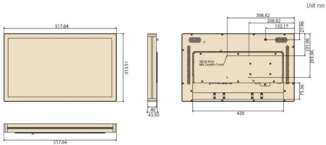
| Dimensions (W x H x D) | 517.64 x 313.51 x 43.50 mm (20.38 x 12.34 x 1.71 in) | |||
| Weight 8 kg (17.6 lb) | ||||
| OS Support | Windows XP/ XPE/ Windows Embedded 7/8 | Windows Embedded 7 (32 bit) | Windows Embed- ded 7/8, Windows 10 IoT Enterprise | |
| Environmental | Operating Temperature | 0 ~ 40 °C (32 ~ 104 °F) | ||
| Relative Humidity | 10 ~ 95% @ 40 °C non-condensing | |||
| Vibration | 0.5 Grms | |||
| Shock | 5 G peak acceleration (11 msec. duration) | |||
| EMC | CE, FCC, UL, CB, CCC, BSMI | |||
| Front Panel Protection | IP65/NEMA4 compliant | |||
| Power | Input Rating | 12 V/5 A (60W ITE adapter) | 12 V/7 A (84W ITE adapter) | |
| Power Consumption | Typical 32W Max. 40W | Typical 45W Max. 65W | ||
| LCD Panel | Size/Type 21.5” TFT LCD with LED backlight | |
| Max.Resolution | 1920 x 1080 | |
| Max. Color 16.7 M | ||
| Pixel Pitch 248 | 25 x 248.25 um | |
| Brightness | 250 cd/m2 (400 cd/m2 optional) | |
| Viewing Angle 1 | 78°/178° | |
| Touchscreen(PE/RE/GE) | Type Glass panel with projected capacitive/5-wire analog resistive touch | |
| LightTransmission | 90% ± 2% / 80%± 5% / 90% | |
| Controller USB | interface | |
1.2.7 UTC-520D/E/F
| System | CPU | Intel® Celeron® J1900 (UTC-520D) | Intel® CoreTM i5-4300U (UTC-520E) Can be equipped with Intel® CoreTM i3-4010U/Celeron® 2980U upon request | Intel® CoreTM i5-6300U (UTC-520F) |
| Base Frequency | 2 GHz (quad-core) 1 | 9 GHz (dual-core) 2.6GHz | Hz (dual-core) | |
| Cache L2 cache | 2 MB L3 cache 3 MB | B L3 cache 4 MB | ||
| Memory | 1 x SODIMM DDR3L 1333 MHz, up to 8 GB | 1 x SODIMM DDR3L 1333/1600 MHz, up to 8 GB | 2 x SODIMM DDR3L 1600 MHz, up to 16 GB | |
| HDD | 1 x 2.5 internal SATA HDD bay | 1 x 2.5 internal SATA HDD bay | 1 x 2.5 internal SATA HDD bay | |
| Network (LAN) | 2 x Gigabit Ethernet ports (with Wake-on-LAN support) | 2 x Gigabit Ethernet ports (with Wake-on-LAN support) | ||
| I/O | 2 x RS-232 COM (RS-422/485 optional) 3 x USB 2.0/1 x USB 3.0 2 x Gigabit Ethernet (RJ-45) 1 x VGA/HDMI 1 x Audio Line-Out 1 x Mic-In | 2 x RS-232 COM (RS-422/485 optional) 2 x USB 2.0/USB 3.0 2 x Gigabit Ethernet (RJ-45) 1 x VGA/HDMI 1 x Audio Line-Out 1 x Mic-In | 2 x RS-232 COM (RS-422/485 optional) 3 x USB 2.0/2 x USB 3.0 2 x Gigabit Ethernet (RJ-45) 1 x VGA/HDMI 1 x Audio Line-Out 1 x Mic-In | |
| Stereo Speaker | 2 x 3W | |||
| Bus Expansion | 1 x Full-size mini PCIe/mSATA | |||
| Mount Options | VESA 100 x 100 mm | |||
| Dimensions (W x H x D) | 517.64 x 313.51 x 43.50 mm (20.37 x 12.34 x 1.71 in) | |||
| Weight | 8 kg (17.6 lb) | |||
| OS Support | Windows Embedded 7/8, Windows 10 IoT Enterprise, Linux Ubuntu 14.04, Android 4.4.2 | Windows Embedded 7/8, Windows 10 IoT Enterprise | - | |
| Environmental | Operating Temperature | 0 ~ 40 °C (32 ~ 104 °F) | ||
| Relative Humidity | 10 ~ 95% @ 40 °C non-condensing | |||
| Vibration 0.5 Grms | ||||
| Shock 5 G peak acceleration (11 msec. duration) | ||||
| EMC/Safety CE, FCC, UL, CCC CB, BSMI | ||||
| Front Panel Protection | IP65/NEMA4 compliant | |||
| Power Supply | Input Rating | 12 V/5 A (60W ITE adapter) | 12 V/7 A (84W ITE adapter) | |
| Power Consumption | Typical 40W Max. 50W | Typical 45W Max. 65W | Typical 40W Max. 50W | |
| LCD Panel | Size/Type 21.5" TFT LCD with LED backlight | |||
| Max. Resolution | 1920 x 1080 | |||
| Max. Color 16.7M | ||||
| Pixel Pitch (H x V) | 248.25 x 248.25 um | |||
| Brightness | 250 cd/m2 (400 cd/m2 optional) | |||
| Viewing Angle | 178°/178° | |||
| Touchscreen (PE/RE/GE) | Type Glass panel with projected capacitive/5-wire analog resistive touch | |||
| Light Transmission | 90% ± 2% / 80% ± 5% / 90% | |||
| Controller USB interface | ||||
1.2.8 UTC-520G
| System | CPU | Intel® Pentium® N4200 (UTC-520G) Intel® Atom® E3950 (available upon request) |
| Base Frequency | 1.1 GHz (N4200/quad-core) 1.6 GHz (E3950/quad-core) | |
| Cache L2 cache 2 | MB | |
| Memory | 1 x 204-pin SODIMM DDR3L | |
| HDD 1 x 2.5 internal SATA HDD bay | ||
| Network (LAN) 2 x | Gigabit Ethernet ports (with Wake-on-LAN support) | |
| I/O | 2 x RS-232 COM (RS-422/485)* 2 x USB2.0/ 2 x USB3.0 2 x Gigabit Ethernet (RJ-45) 1 x VGA 1 x HDMI 1 x Audio Line-Out 1 x Mic-In | |
| Stereo Speaker 2 x | 3W | |
| Bus Expansion 1 x | Full-size mini PCIe / M.2 | |
| Mount Options VESA | 100 x 100 mm | |
| Dimensions (W x H x D) | 517.64 x 313.51 x 43.50 mm (20.37 x 12.34 x 1.71 in) | |
| Weight 8 kg (17.6 lb) | ||
| OS Support | Windows 10 IoT Enterprise Android 6.0 Linux Ubuntu 17.04 | |
| Environmental | Operating Temperature | 0 ~ 40 °C (32 ~ 104 °F) |
| Relative Humidity | 10 ~ 95% @ 40 °C non-condensing | |
| Vibration 0.5G | ||
| Shock 5G peak acceleration (11 msec. duration) | ||
| Certification CE, FCC, CB, UL, CCC, BSMI | ||
| Front Panel Protection | IP65/ NEMA4 compliant | |
| Power Supply | Input Rating | 12 V/5 A (60 W ITE adapter) |
| Power Consumption | Typical 40W Max. 60W | |
| LCD Panel | Size/Type | 21.5" TFT LCD with LED backlight |
| Max. Resolution | 1920 x 1080 | |
| Max. Color | 16.7M | |
| Pixel Pitch | 248.25 (H) x 248.25 (V) | |
| Brightness | 250 cd/m2 (400 cd/m2 optional) | |
| Viewing Angle | 178°/178° | |
| Touchscreen (PE/RE/GE) | Type | Glass panel with projected capacitive/5-wire analog resistive touch |
| Light Transmission | 90% ± 2%/80% ± 5%/ 90% | |
| Controller | USB interface | |
1.2.9 UTC-532A/C
| System | CPU | AMD® G-Series T40E dual-core 1.0 GHz (UTC-532A) | Intel® CoreTM i7 3517UE 1.7 GHz (UTC-532C) |
| Chipset T40E + A | 50M Intel® QM77 | ||
| Cache L2 cache | 512 KB | L2 cache 1 MB(L3 cache 4 MB) | |
| Memory | 1 x SODIMM DDR3 1066 MHz, up to 4 GB | 1 x SODIMM DDR3/DDR3L1333/1600 MHz, up to 8 GB | |
| HDD 1 x 2.5 internal SATA HDD bay | |||
| Network (LAN) 2 | x Gigabit Ethernet ports | ||
| I/O | 3 x RS-232 COM(RS-422/485 optional)4 x USB 2.02 x Gigabit Ethernet (RJ-45)1 x VGA/HDMI1 x Audio Line-Out1 x Mic-In | 2 x RS-232 COM(RS-422/485 optional)2 x USB 2.0, 2 x USB 3.02 x Gigabit Ethernet (RJ-45)1 x VGA/HDMI1 x Audio Line-Out1 x Mic-In | |
| Stereo Speaker 2 | x 3W | ||
| Bus Expansion | 1 x Full-size mini PCIe/mSATA | ||
| Dimensions(W x H x D) | 785.64 x 480.24 x 62.50 mm (30.93 x 18.9 x 2.46 in) | ||
| Weight 1 18 kg (39.6 lb) | |||
| OS Support | Windows XP/XPE, Windows Embedded 7/8 | Windows Embedded 7/8, Windows 10 IoT Enterprise | |
| Environmental | Operating Temperature | 0 ~ 40 °C (32 ~ 104 °F) | |
| Relative Humidity | 10 ~ 95% @ 40 °C non-condensing | ||
| Vibration 0.5 Grms | |||
| Shock | 5 G peak acceleration (11 msec. duration) | ||
| EMC | CE, FCC, UL, CB, CCC, BSMI | ||
| Front Panel Protection | IP65/NEMA4 compliant | ||
| Power Supply | Input Rating | 100 ~ 240 V_AC 50/60 Hz 2.5A | |
| Power Consumption | Typical 95WMax. 105W | ||
| LCD Panel | Size/Type | 32" TFT LCD with LED backlight | |
| Max. Resolution | 1920 x 1080 | ||
| Max. Color | 16.7M | ||
| Pixel Pitch | 0.36375 x 0.36375 mm | ||
| Brightness | 300 cd/ m^2 | ||
| Viewing Angle | 178°/178° | ||
| Touchscreen (PE/GE) | Type | Glass panel with projected capacitive touch (no touch function optional) | |
| Light Transmission | 90% ± 2% / 90% | ||
| Controller | USB interface | ||
1.2.10 UTC-532E/F/G
| System | CPU | Intel® Pentium®N4200 (UTC-532G)Intel® Atom® E3950(available upon request) | Intel® CoreTM i5-6300U (UTC-532F) | Intel® CoreTM i5-4300U (UTC-532E)Intel® CoreTM i3-4010U(available upon request)Intel® Celeron® 2980U(available upon request) |
| BaseFrequency | 1.1 GHz (N4200/ quad-core)1.6 GHz (E3950/ quad-core) | 2.4GHz (dual-core) 1.9 | 9 GHz (dual-core) | |
| Cache L2 cache | 2 MB L3 cache 3 MB | L3 cache 3 MB | ||
| Memory | 1 x 204-pin SODIMM DDR3L 1867 MHz, up to 8 GB | 2 x 204-pin SODIMM DDR3L 1600 MHz, up to 16 GB | 1 x 204-pin SODIMM DDR3L 1333/1600 MHz, up to 8 GB | |
| HDD 1 x 2.5 internal SATA HDD bay | 1 x 2.5 internal SATA HDD bay | |||
| Network (LAN) | 2 x Gigabit Ethernet ports (with Wake-on-LAN support) | |||
| I/O | 2 x RS-232 COM (RS-422/485)*2 x USB2.0/ 2 x USB3.02 x Gigabit Ethernet (RJ-45)1 x VGA1 x HDMI1 x Audio Line-Out1 x Mic-In | 2 x RS-232 COM (RS-422/485)*2 x USB 2.0 / 2 x USB 3.02 x Gigabit Ethernet (RJ-45)1 x VGA & 1 x HDMI1 x Audio Line-Out1 x Mic-In | ||
| StereoSpeaker | 3 W x 2 | |||
| BusExpansion | 1 x Full-size mini PCIe/M.2 | 1 x Full-size mini PCIe/mSATA | ||
| Dimensions(W x H x D) | 764.5 x 459 x 62.5 mm (30 x 18 x 2.46 in) | |||
| Weight 18 kg (39.6 lb) | ||||
| OS Support | Windows 10 IoT EnterpriseAndroid 6.0Linux Ubuntu 17.04 | WES 7P 32 bitWES 7E 32 bitWindows Pro Embedded 7 SP1 64 bitWES 8 64 bitWindows Embedded 8.1 Industry Pro 64 bitWindows 10 IoT EnterpriseLinux Ubuntu 16.04 | WES 7P 32 bitWES 7E 32 bitWindows Pro Embedded 7 SP1 64 bitWES 8 64 bitWindows Embedded 8.1 Industry Pro 64 bitWindows 10 IoT EnterpriseLinux Ubuntu 16.04 | |
| Environmental | Operating Temperature | 0 ~ 40°C (32 ~ 104°F) |
| Relative Humidity | 10 ~ 95% @ 40°C non-condensing | |
| Vibration 0.5G | ||
| Shock 5 G peak acceleration (11 msec. duration) | ||
| EMC CE, FCC, UL, CB, CCC, BSMI | ||
| Front Panel Protection | IP65/ NEMA4 compliant | |
| Power Supply | Input Rating 100 ~ 240 V AC ~ 50/60 Hz 2.5A | |
| Power Consumption | Typical 95W Max. 105W | |
| LCD Panel | Size/Type 31.5" TFT LCD with LED backlight | |
| Max. Resolution | 1920 x 1080 | |
| Max. Color 16.7 M | ||
| Pixel Pitch 0.36375 x 0.36375 mm | ||
| Brightness | 300 cd/m2 | |
| Viewing Angle | 178°/178° | |
| Touchscreen (PE/GE) | Type | Glass panel with projected capacitive touch/glass panel with no touch function |
| Light Transmission | 90% ± 2%/90% | |
| Controller USB | interface | |
1.2.11 UTC-542D/F/G
| System | CPU | Intel® Celeron® J1900 (UTC-542D) | Intel® CoreTM i5-6300U (UTC-542F) Intel® CoreTM i7-6600U (available upon request) Intel® CoreTM i3-6100U (available upon request) | Intel® Pentium® N4200 (UTC-542G) Intel® Atom® E3950 (available upon request) |
| Base Frequency | 2 GHz (quad-core) 2.4 | GHz (dual-core) | 1.1 GHz (N4200/quad-core) 1.6 GHz (E3950/quad-core) | |
| Cache 2 MB | 3 MB L2 cache 2 MB | |||
| Memory | 1 x 204-pin SODIMM DDR3L 1333 MHz | 2 x 204-pin SODIMM DDR3L 1600Mhz | 1 x 204-pin SODIMM DDR3L 1867 MHz | |
| HDD/SSD Dual hot-swappable HDD/SSD slots with RAID 0,1 support | ||||
| Network (LAN) | 2 x Gigabit Ethernet ports | |||
| I/O | 2 x RS-232 COM (RS-422/485)* 4 x USB 2.0 / 1 x USB 3.0 2 x Gigabit Ethernet (RJ-45) 1 x VGA 1 x HDMI | 2 x RS-232 COM (RS-422/485)* 3 x USB 2.0 / 2 x USB 3.0 2 x Gigabit Ethernet (RJ-45) 1 x VGA 1 x HDMI | ||
| Stereo Speaker | 2 x 10W | |||
| Bus Expansion | 1 x Full-size mini PCIe/mSATA | |||
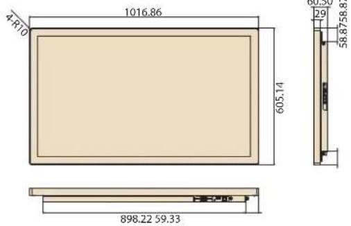
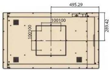
| Dimensions (W x H x D) | 990.6 x 578.8 x 60.2 mm (Mirror Glass) 1016.9 x 605.2 x 60.5mm (Pcap / Mirror Pcap*) | |||
| Weight 24.6 kg | ||||
| OS Support | WES 7P 32 bit WES 7E 32 bit Windows Pro Embedded 7 SP1 64 bit WES 8 64 bit Windows Embedded 8.1 Industry Pro 64 bit Windows 10 IoT Enterprise Linux Ubuntu 16.04 Android 4.4.2** | WES 7P 32 bit WES 7E 32 bit Windows Pro Embedded 7 SP1 64 bit WES 8 64 bit Windows Embedded 8.1 Industry Pro 64bit Windows 10 IoT Enterprise Linux Ubuntu 16.04 | Windows 10 IoT Enterprise Android 6.0** Linux Ubuntu 17.04 | |
| Environmental | Operating Temperature | 0 ~ 40 °C (32 ~ 104 °F) | ||
| Relative Humidity | 10 ~ 95% @ 40 °C non-condensing | |||
| Vibration 0.5G | ||||
| Shock 5 G peak acceleration (11 msec. duration) | ||||
| Front Panel Protection | IP65/NEMA4 compliant | |||
| Power | Input Rating | 100 ~ 240VAC ~ 50/60 Hz 3.7A | ||
| LCD Panel | Size/Type 42 | .5" TFT LCD with LED backlight | ||
| Max. Resolution | 1920 x 1080 | |||
| Pixel Pitch 0.49 x 0.49 | ||||
| Brightness | 450 cd/m2 | |||
| Viewing Angle | 178°/178° | |||
| Touchscreen (PE/GE) | Type | Glass panel with projected capacitive touch/mirrored glass panel with no touch function/mirrored glass panel with projected capacitive touch* | ||
| Light Transmission | >90% (pure glass); >25% (mirror coated) | |||
| Controller USB interface | ||||
* Mirrored PCAP touchscreen available upon request.
** Only UTC-542D and UTC-542G models support Android OS.
1.3 Dimensions
1.3.1 UTC-510
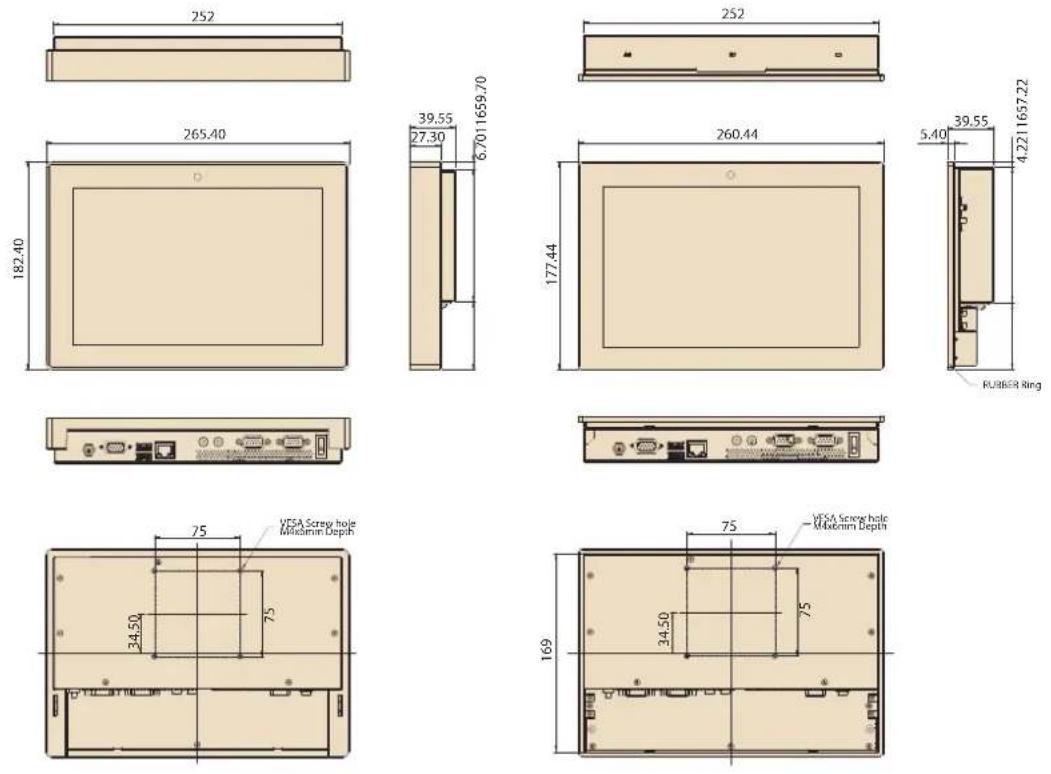
Unit: mm
1.3.2 UTC-515
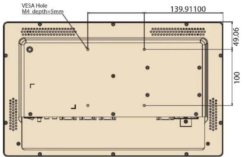
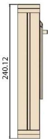
Dimensions: 390 x 240 x 45 mm (15.35 x 9.44 x 1.77 in)
natural_image
Technical drawing of a vertical wooden cabinet or enclosure with a dimension label (240.12) and internal structure (no text or symbols beyond the measurement)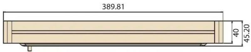
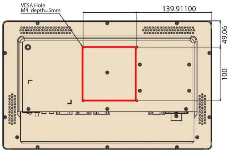
VESA Mount: 100 x 100 mm (3.93 x 3.93 in)
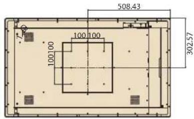
1.3.3 UTC-520
1.3.4 UTC-532
Dimensions: 786 x 480 x 63 mm (30.9 x 18.89 x 2.48 in)
Applies to the following models:
UTC-532F-PE
UTC-532E-PE
UTC-532D-PE
UTC-532C-PE
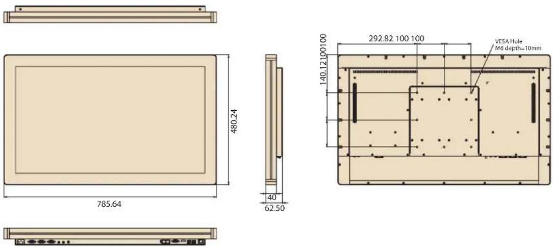
VESA Mounting: 200 x 200 mm (7.87 x 7.87 in)
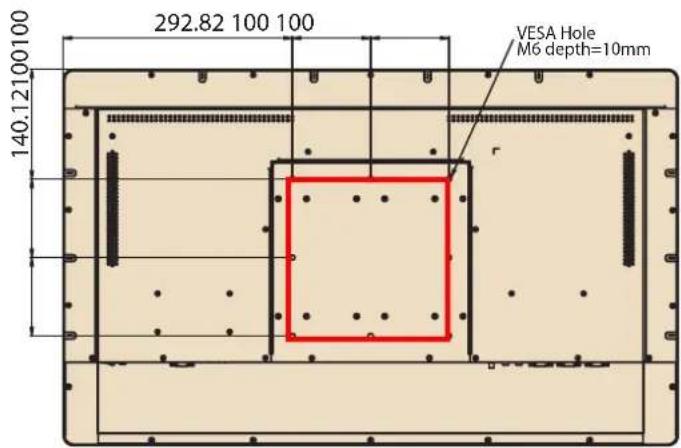
Dimensions: 765 x 459 x 63 mm (30.11 x 18.07 x 2.48 in)
Applies to the following models:
UTC-532GP-ATB0E
UTC-532FP-ATB0E
UTC-532EP-ATB0E
1.3.5 UTC-542
MirrorPcap
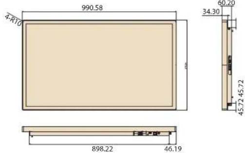
Unit: mm
Chapter 2
System Setup
2.1 Quick Tour
Before setting up the system, take a moment to become familiar with the connector locations and functions, as shown in the images below.
2.1.1 Front View
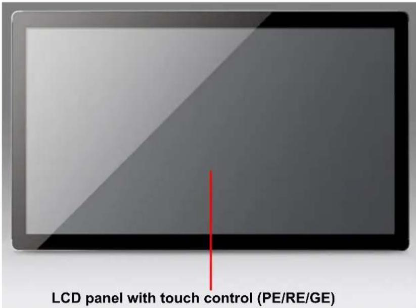
Note! The UTC-515 and UTC-520 PE models feature an anti-microbial Corning® Gorilla® Glass panel with projected capacitive touch control. See Appendix C for additional details. Resistive touch control is not available for the UTC-510/532/542 devices.
2.1.2 Rear View
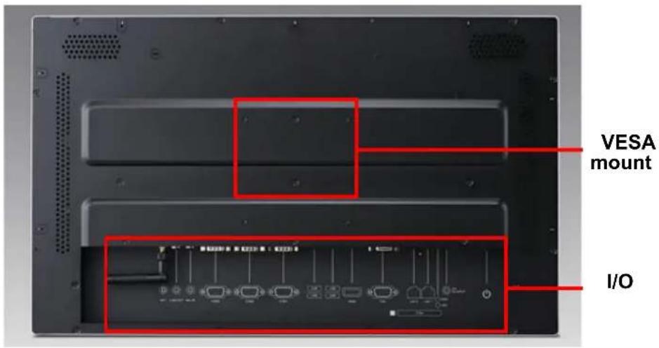
Note! Use only VESA-compatible floor, stand, and wall mount kits. See Appendix A for additional details. Refer to Section 2.2 for information regarding the system I/O, according to the specific UTC model.
2.1.3 Side View
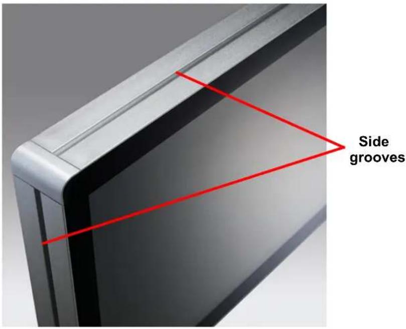
Note! The UTC-500 series devices (excluding the UTC-510/542 models) feature unique side grooves for easy integration of peripherals using two screws. Refer to Section 3.6 for installation information.

2.2 I/O Ports
2.2.1 UTC-510
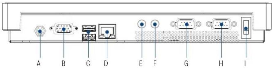
A. DC power jack F. Line-out
B. VGA G. COM 2
C. 1 x USB 3.0, 1 x USB 2.0 H. COM 1
D. LAN I. Power switch
E. Mic-In
2.2.2 UTC-510(PoE)
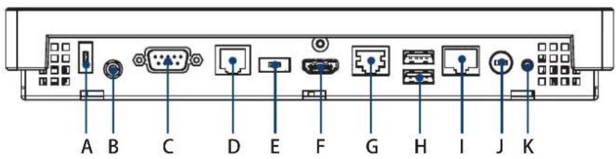
A. USB 2.0 (DC version only) G. LAN
B. Headset H. 2 x USB 2.0
C. COM1 I. LAN/PoE
D. COM2 J. DC power jack (DC version only)
E. USB 3.0 (DC version only) K. Power switch
F. HDMI
With the standard UTC-510 PoE model, users are recommended to avoid using the USB 2.0 (A) and USB 3.0 (E) ports. To change the configuration, the total power input must be under 25.5 W.
Caution!

The UTC-510 (PoE) model is a PoE-powered device that consumes energy. Always use power sourcing equipment (PSE) that complies with the IEEE 802.3at PoE standard, also known as "PoE+" or "PoE plus", and provides up to 30W of DC power output because only 25.5W is guaranteed to be available because of in-cable power dissipation.
2.2.3 UTC-515
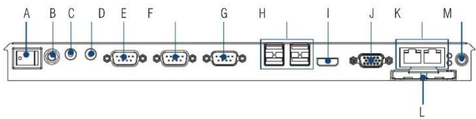
A. Power switch H. 4 × USB 2.0
B. Antenna connector (2 x USB 3.0 for UTC-515C/E/F)
C. Line-Out I. HDMI
D. Mic-In J. VGA
E. COM3 (UTC-515A/B only) K. 2 x LAN
F. COM2 L. CFast (UTC-515A/B only)
G. COM1 M. DC input
2.2.4 UTC-520
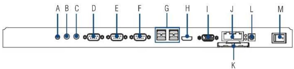
A. Antenna connector H. HDMI
B. Line-Out I. VGA
C. Mic-In J. 2 x LAN
D. COM3 (UTC-520A/B only) K. CFast (UTC-520A/B only)
E. COM2 L. DC input
F. COM1 M. Power switch
G. 4 x USB 2.0 (1 x USB 3.0 for UTC-520D; 2 x USB 3.0 for UTC-520C/E)
2.2.5 UTC-532

A. Power switch F. Antenna connector
B. 4 × USB 2.0 G. Line-Out
(1 x USB 3.0 for UTC-532D; H. Mic-In
2 x USB 3.0 for UTC-532C/E) I. COM3 (UTC-532A only)
C. HDMI J. COM2
D. VGA K.COM1
E. 2 × LAN L. AC input
2.2.6 UTC-542

A. Antenna connector G. HDMI
B. Power switch H. 1 x USB 3.0, 3 x USB 2.0 (UTC-542D)
C. 2 x COM USB 3.0 x 2, USB 2.0 x 2 (UTC-542F)
D. Mic-In/Line-Out I. AC power
E. 2 x LAN J. Antenna connector
F. VGA
2.3 Setup Procedures
2.3.1 System Power On
- For the UTC-510 model, connect the system to a power adaptor with 12V/3A input voltage. For the UTC-515 and UTC-520A/B/C/D/E models, a 12V/5A power adaptor. For the UTC-520C/E models, a 12V/7A power adaptor. For the UTC-532/542 models, connect the system to an AC power cable.
- Hold power cords by the plugs ends only. Refer to Section 2.2 for the location of the DC/AC power input and power switch.
- Press the power switch to activate the system. The PWR LED should emit a green light.
2.3.2 BIOS Setup
For most UTC series, the system setup and configuration will be completed by the dealer or system integrator prior to delivery. However, users may still need to access the BIOS setup program to adjust the system configuration, such as the date/ time or hard drive type. The setup program is stored in read-only memory (ROM) and can be accessed following system reset or by pressing the "Del" key after powering on the computer. The settings selected in the setup program are recorded in CMOS RAM memory, which is backed up by a battery to ensure the settings are retained after the system is powered off. When booting up, the system compares the settings stored in CMOS RAM with the POST self test results. If a discrepancy is found, an error message is displayed on screen and users are prompted to run the setup program.
2.3.3 System Software Installation
Recent releases of operating systems from major vendors include setup programs that load automatically and guide users through hard disk preparation and operating system installation. Some distributors and system integrators may have already installed software prior to shipping the product.
Note! Before software or driver installation, the system must be equipped with additional storage that users must purchase separately.

2.3.4 Driver Installation
After installing the system software, users can set up the Ethernet, XGA, audio, and touchscreen functions.
Note! The relevant drivers and utilities are subject to change without notice.

Download the latest drivers for UTC series products from the Advantech website at http://support.advantech.com or contact our application engineers for further assistance.
Chapter 3
Upgrades and Installation
3.1 Introduction
Advantech's UTC series systems are PC-based computers housed in an aluminum enclosure. To perform system maintenance or hardware upgrades, such as installing an HDD, DRAM, or CompactFlash (A/B models only), simply remove the unit's rear cover.
Warning! Do not remove the rear cover until you have verified that power is not flowing within the device. The system power should be switched off and the power cord unplugged before opening the device enclosure.

3.2 Installing a 2.5" SATA HDD
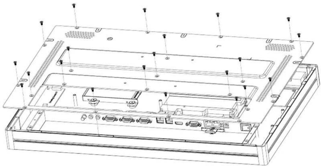
UTC systems feature a 2.5" SATA HDD bay reserved for customizable storage. To install a 2.5" SATA HDD, follow the steps below.
- Loosen the affixing screws and remove the rear cover.
- Insert the SATA HDD into the metal bracket and fasten in place with screws.
- Use a power cable to connect the SATA HDD to the power supply unit.
- Use a SATA data cable to connect the SATA HDD to the motherboard.
- Replace the rear cover and tighten the screws.
natural_image
Technical line drawing of an internal server rack with multiple ports and mounting holes (no text or symbols)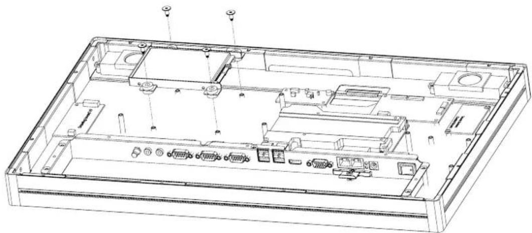
natural_image
Technical line drawing of an open computer chassis showing internal components and connectors (no text or labels)3.3 Installing a CFAST Card (A/B Models Only)
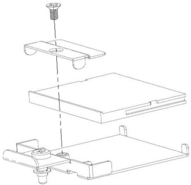
The image below illustrates the process for installing a CFAST card. (Note the direction of the CFAST card during assembly).
natural_image
Technical line drawing of a mechanical assembly with three stacked components and a screw head (no text or symbols)3.4 Installing a Memory Module
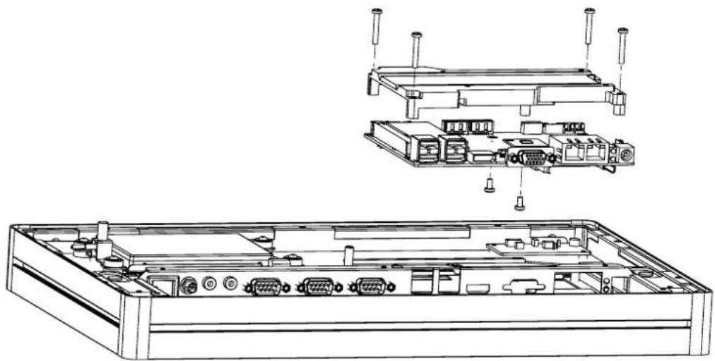
- Loosen the affixing screws and remove the rear cover.
- Remove the 4 screws from the DRAM memory module heatsink.
- Turn the memory module over and remove the 2 screws on the underside.
- Install the DRAM module into the SODIMM socket.
natural_image
Technical line drawing of an electronic device chassis showing internal components and external casing (no text or labels)3.5 Installing a Wireless LAN Card (Optional)
- Loosen the affixing screws and remove the rear cover.
- Remove the four screws holding the heatsink in place.
- Insert the WLAN card into the mini PCIe slot located on the underside of the motherboard.
- Connect a coaxial cable to ANT1 and ANT2 ports on the WLAN card.
- Install the antenna brackets, washers, and nuts inside chassis.
- Reassemble the back cover.
- Install the antenna on SMA connector on chassis exterior.
Note! If the motherboard is removed from the chassis and the cables detached

and reattached, Pin 1 of the header can be located by aligning the red side of the ribbon cable to the edge indicated by a small triangle marking on the PCB.
3.6 Installing Peripherals (Optional)
3.6.1 UTC-510/510(PoE)
Installing Optional Modules
- Attach the peripheral module to the bottom of the UTC system.
- Affix the module in place using the screws removed from the frame.
- Connect a cable to the peripheral module and to an I/O port (USB).
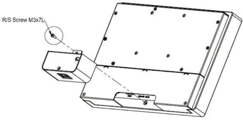
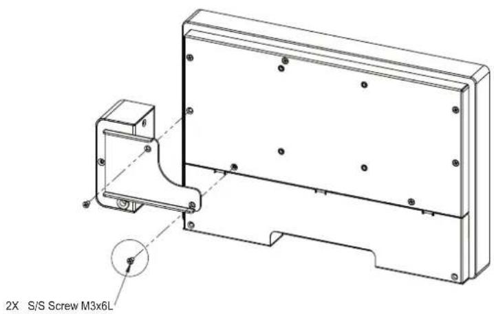
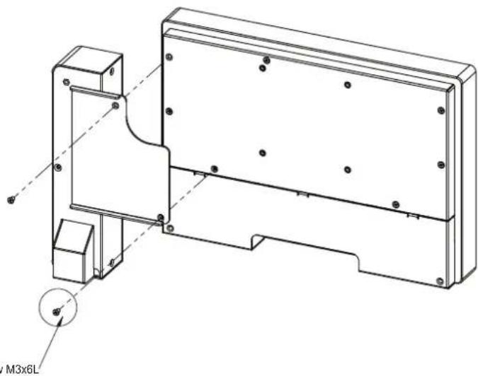
natural_image
Technical line drawing of a mechanical assembly with mounting brackets and a circular detail labeled M3x6L (no text or symbols beyond label)2X S/S Screw M3x6L
3.6.2 UTC-515/520/532
-
Affix the peripheral module to the computing device via the side grooves.
-
Use two screws to fasten the module in place.
-
Connect a cable to the peripheral module and to an I/O port (USB).
-
Place the cable clamp in a secure location and attach the cable to it for simple cable routing.
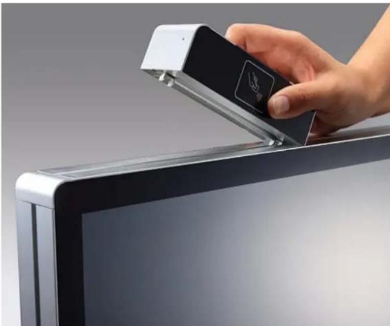
natural_image
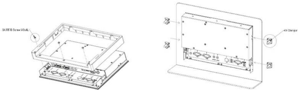
Hand inserting a black USB into a flat-screen monitor (no text or symbols visible)3.7 Panel Mount Installation for UTC-510
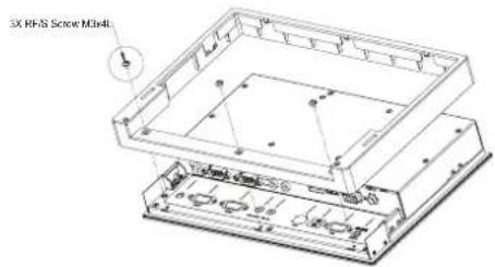
3.8 Installing a DRAM Module for UTC-510
3.8.1 UTC-510
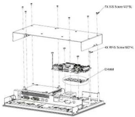
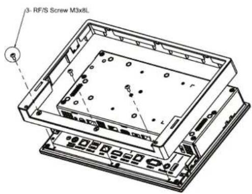
3.8.2 UTC-510(PoE)

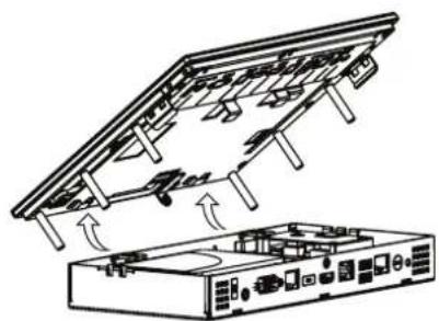
natural_image
Technical line drawing of a server rack with cooling fans and ventilation slots (no text or symbols)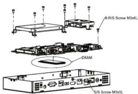
3.9 Installing an SSD Module for UTC-510
3.9.1 UTC-510
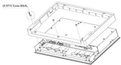
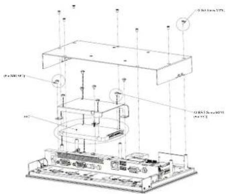
3.9.2 UTC-510(PoE)
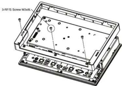
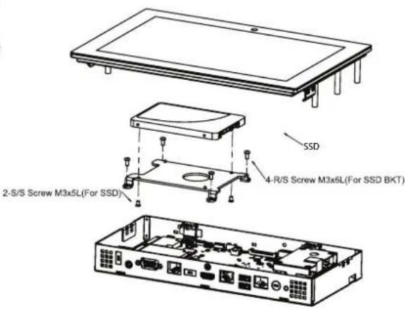
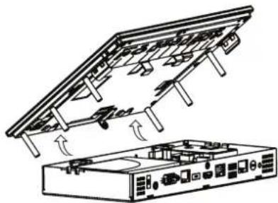
natural_image
Technical line drawing of a device with an open rear panel and internal components (no text or symbols)3.10 Installing an mSATA SSD Module for UTC-510
3.10.1 UTC-510
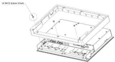
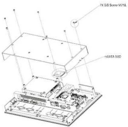
3.10.2 UTC-510(PoE)
natural_image
Technical line drawing of a device chassis with internal components and directional arrows indicating assembly (no text or symbols)3.11 Installing a Wi-Fi Module for UTC-510
3.11.1 UTC-510
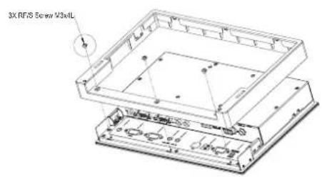
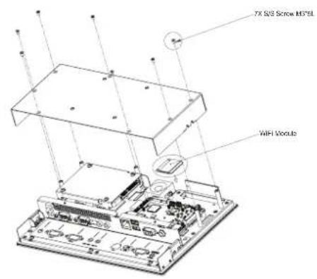
3.11.2 UTC-510(PoE)
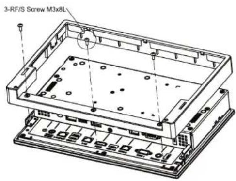
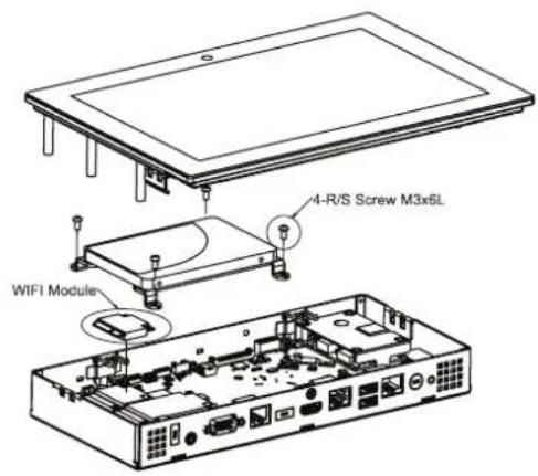
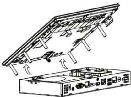
natural_image
Diagram of a device with an open panel and internal components, showing airflow direction (no text or symbols)Appendix A
Installation Accessories
A.1 Introduction
The floor stand and wall mount accessories provided for Advantech's UTC series systems combine simplicity with style, making them easy to install without additional cost or space requirements. Additionally, because the UTC series are aimed at supporting applications in diverse usage scenarios, such as self-service kiosks in hospitality reception areas, the units are slim and compact, and feature an attractive elegant appearance that ensures integration in a variety of environments.
A.2 Wall Mount
| Part Number | UTC-WALLMOUNT1E UTC-WALLMOUNT2E UTC-WALLMOUNT3E | ||
| Description | VESA mount 75/100 mm | VESA mount 100/200 mm | VESA mount 75/100 mm |
| VESA Mount Pattern | 75 x 75 mm100 x 100 mm | 200 x 200 mm | 75 x 75 mm100 x 100 mm |
| Weight Capacity | 14 kg (30.86 lb) 35 kg (77.16 lb) 20 kg (44.09 lb) | ||
UTC-WALL-MOUNT1E
VESA 75/100 mm
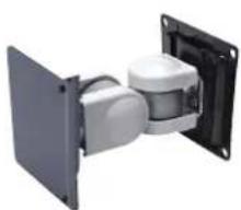
natural_image
3D rendering of a mechanical assembly with two white components mounted on a dark panel (no text or symbols visible)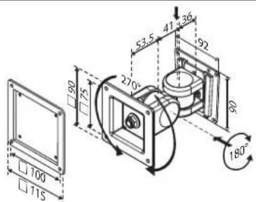
■ Can be firmly fixed to a wall
■ Weight capacity: Up to 14 kg (30.86 lb)
Material: Steel
■ Tilt range: 180° up and down
■ Rotation: 270° for portrait or landscape orientation
■ Lift: 130.5 mm (5.13 in)
For UTC-515/520
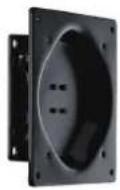
UTC-WALL-MOUNT2E
VESA 100/200 mm
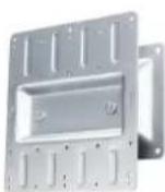
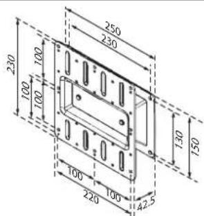
■ Flush fit without movement
■ Weight capacity: Up to 35 kg (77.16 lb)
Material: Steel
■ Sits: 42.5 mm (1.67 in) from the wall
■ for UTC-532 only
UTC-WALL-MOUNT3E
VESA 75/100 mm
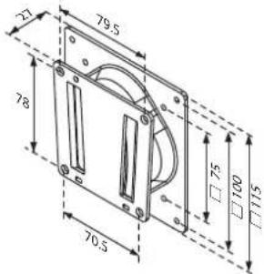
■ Can be firmly fixed to a wall
■ Weight capacity: Up to 20 kg (44.09 lb)
Material: Steel
■ Sits: 27 mm (1.06 in) from the wall
For UTC-515/520
A.3 Floor Stand
Part Number UTC-T01-STANDE UTC-H01-STANDE
Description Triangular floor stand H-shape floor stand
VESA Mount Pattern 75 x 75 mm; 100 x 100 mm 75 x 75 mm; 100 x 100 mm
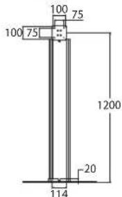
Height 120 cm (47.2 in) 120 cm (47.2 in)
Dimensions ∅660 mm (25.98 in) 58 x 510 mm (2.28 x 20.07 in)
Weight 10 kg (22.04 lb) 10 kg (22.04 lb)
UTC-T01-STANDE
Triangular Floor Stand
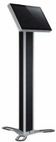
natural_image
Modern black and silver stand with a flat top and metal legs (no text or symbols visible)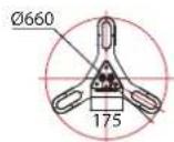
Organized cable management
■ VESA 75/100 mm
Height: 120 cm (47.2 in)
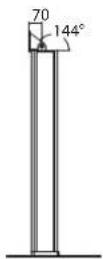
■ Easy tilt for optimum viewing comfort
■ Dimensions: ∅660 mm (25.98 in)
■ Weight: 10 kg (22.04 lb)
UTC-H01-STANDE
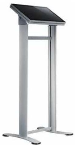
H-Shape Floor Stand
natural_image
Modern vertical stand with a black screen and metallic legs (no text or symbols visible)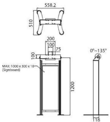
■ Organized cable management
■ VESA 75/100 mm
■ Height: 120 cm (47.2 in)
■ Easy tilt for optimum viewing comfort
■ Dimensions: ∅660 mm (25.98 in)
■ Weight: 10 kg (22.04 lb)
■ Acrylic signboard not included
Appendix B
UTC Peripherals
B.1 UTC-P01 (Camera Module)
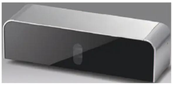
natural_image
3D rendering of a rectangular electronic device with a glossy surface and a small circular cutout on the side (no text or symbols visible)B.1.1 Specifications
| Interface USB (cable length: 50 cm/19.68 in) | |
| Image Resolution 2592 (H) x 1944 (V) | |
| Focusing Range 10 cm ~∞; supports auto focus | |
| Frame Rate | 640 x 480 @ 30 fps max. |
| 1280 x 1024 @ 30 fps max. | |
| 1600 x 1200 @ 15 fps max. | |
| 2592 x 1944 @ 15 fps max. | |
| Video Format MJPG | |
| OS Support Windows XP/7/8 | |
| Dimensions 130 x 35 x 40 mm/5.11 x 1.37 x 1.57 in | |
| Operating Temperature 0 ~ 40 °C/32 ~ 104 °F | |
B.1.2 Packing List
| Description Quantity |
| Cable clamp 2 |
| Camera module 1 |
B.1.3 Ordering Information
| Part Number | Description |
| UTC-P01-A1E | 5 megapixel camera module for UTC-500 series |
B.2 UTC-P02 (MSR)
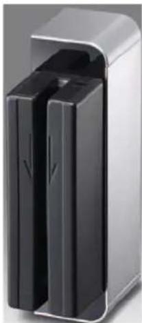
natural_image
Exterior view of a modern office building (no signage)B.2.1 Specifications
| Interface USB (cable length: 50 cm/19.68 in) | |
| Track Configuration | TRACK 1/IATA/210 bpi/79 alphanumeric characters |
| TRACK 2/ABA/75 bpi/40 numeric characters | |
| TRACK 3/thrift/210 bpi/107 numeric characters | |
| Card Standard ANSI, ISO, ABA | |
| Read Speed 3 ~ 60 ips (7 ~ 152 cm/s) | |
| Magnetic Head Life 1,000,000 times (ISO test standard) | |
| OS Support Windows 98/ME/2000/XP/7 | |
| Dimensions 130 x 35 x 40 mm/5.11 x 1.37 x 1.57 in | |
| Operating Temperature | 0 ~ 40 °C/32 ~ 104 °F |
B.2.2 Packing List
| Description Quantity | |
| Cable clamp 2 | |
| Magnetic strip reader module | 1 |
B.2.3 Ordering Information
| Part Number Description | |
| UTC-P02-A0E | Magnetic strip reader for UTC-500 series |
B.3 UTC-P03 (RFID Reader)
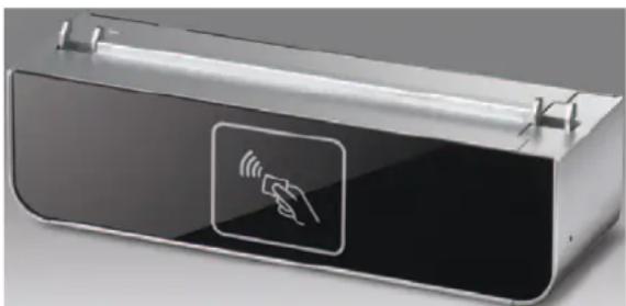
natural_image
Exterior view of a modern office building (no signage)B.3.1 Specifications
| Interface USB (cable length: 50 cm/19.68 in) |
| Frequency 13.56 MHz |
| Read Mode ISO 15693, ISO 14443A, ISO 14443B, ISO 18000- 3 Mode 1, FeliCa |
| Card Mode Simulates ISO14443A mode |
| P2P Mode NFCIP-1, NFCIP-2, ISO 18092, 848 ~ 106 kps |
| Support Tag Specifications | ||||
| Standard Tag Model UID | Read/Write Data | Applications | ||
| ISO 15693 | NXP I-Code 2(SLI) | Yes Yes | ||
| Texas Instruments Tag-it | Yes | Yes | ||
| MStar MSR3200 | Yes | Yes | Library, medical, supply chains | |
| Other ISO15693 compatible tag | OK | Yes | ||
| ISO 14443A | NXP MIFARE® Ultralight | Yes | Yes | Transportation |
| NXP MIFARE® | Yes | Access control | ||
| ISO 14443B | ST | Yes | Yes | |
| ATMEL | Yes | Yes | ||
| ISO 14443A | SONY-FeliCa (Suica/Edy card) | Yes | Japanese railways | |
| Reading Range | 3 cm ± 1 cm | |||
| OS Support | Windows XP/7 | |||
| Dimensions | 130 x 35 x 40 mm/5.11 x 1.37 x 1.57 in | |||
| Operating Temperature | 0 ~ 40 °C/32 ~ 104 °F | |||
B.3.2 Packing List
| Description | Quantity |
| Cable clamp | 2 |
| RFID reader module | 1 |
B.3.3 Ordering Information
Part Number Description
UTC-P03-A0E RFID reader for UTC-500 series
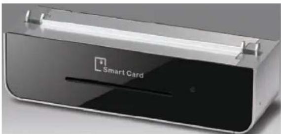
B.4 UTC-P06 (Smart Card Reader)
natural_image
Exterior view of a Smart Card device with visible logo and circuit lines (no text or symbols beyond branding)B.4.1 Specifications
| Interface USB (cable length: 50 cm/19.68 in) | |
| Card Acceptor/Reliability | User card friction type (ID-1), 200,000 cycles |
| Card Reader | CPU card, compliant with ISO7816-1,2,3,T=1 and T=0 protocols |
| Memory card, synchronous 2-line, 3-line, and I2C interface | |
| LED | Dual-color LED indicators |
| Compliant with PC/SC, Version 1.0, standards | |
| OS Support Windows XP/ 7 | |
| Dimensions 130 x 35 x 40 mm/5.11 x 1.37 x 1.57 in | |
| Operating Temperature 0 ~ 40 °C/32 ~ 104 °F | |
B.4.2 Packing List
| Description Quantity | |
| Cable clamp 2 | |
| Smart card reader module | 1 |
B.4.3 Ordering Information
| Part Number | Description |
| UTC-P06-A0E | Smart card reader for UTC-500 series |
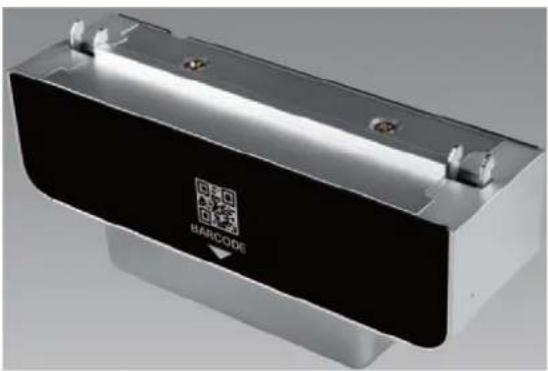
B.5 UTC-P07 (Barcode Reader)
natural_image
Exterior view of a modern office building (no signage)B.5.1 Specifications
| Interface USB (cable length: 50 cm/19.68 in) | |
| Scanning Performance | Scan rate: 2D mode; 53 images/s |
| Scan angle: 40°/26° | |
| Optical resolution: 752 (H) x 480 (V) pixels, 256 gray levels | |
| Typical Reading Distances | Symbology Density Min. Distance Max. Distance |
| Code 39 0.125 mm/5 mils 4.7 cm/1.8 in 17.7 cm/7.0 in | |
| UPC/EAN 0.33 mm/13 mils 2.5 cm /1.0 in 41.9 cm/16.5 in | |
| Data Matrix 0.254 mm/10 mils 2.7 cm /1.0 in 17.1 cm/6.7 in | |
| PDF 417 0.254 mm/10 mils 2.2 cm /0.9 in 2.2 cm /9.4 in | |
| * Minimum distance depends on symbology length and scan angle | |
| Symbologies | 1D/Linear Symbologies: Automatically discriminates all standard 1D codes including GS1DataBarTM linear codes |
| 2D Symbologies: Aztec code, China Han Xin code, DataMatrix, MaxiCode, Micro QR code, and QR code | |
| Postal Codes: Australian Post, British Post, China Post, IMB, Japanese Post, KIX Post, Korea Post, Planet Code, Postnet, Royal Mail Code (RM4SCC) | |
| Stacked Codes: EAN/JAN composites, GS1 DataBar composites, GS1 DataBar expanded stacked, GS1 DataBar stacked, GS1 DataBar | |
| Stacked omnidirectional, MacroPDF, MicroPDF417, PDF417, UPC A/E composites | |
| OS Support Windows 7/8 | |
| Dimensions | 130 x 52 x 40 mm/5.11 x 2.04 x 1.57 in |
| Operating Temperature | 0 ~ 40 °C/32 ~ 104 °F |
B.5.2 Packing List
Description Quantity
Cable clamp 2
Barcode reader module 1
B.5.3 Ordering Information
Part Number Description
UTC-P07-A1E 2D barcode reader for UTC-500 series
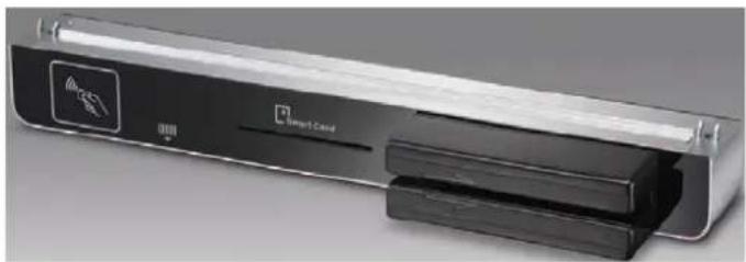
B.6 UTC-P21 (4-in-1 Module)
natural_image
Exterior view of a Smart Care device with visible logo and internal components (no text or symbols on main body)B.6.1 Specifications
| RFID | 13.56 MHz frequency |
| Read mode: ISO 15693/14443A/B/18000-3/FeliCa | |
| Reading range: 3 +/- 1cm | |
| 2D Barcode Reader | 2D mode scan rate: 56 images |
| Linear emulation scan rate: 200 images/sec | |
| Optical resolution: 752 x 480 pixels, 256 gray levels | |
| Smart Card Reader | User card friction type (ID-1), 200,000 cycles |
| SAM card: 5000 insertion | |
| Compliant with CPU and memory cards | |
| Magnetic Strip Reader | Card standards: ANSI, ISO, ABA |
| Read speed: 3 ~ 60 ips (7 ~ 152 cm/s) | |
| Magnetic head life: 1,000,000 times (ISO test standard) | |
| OS Support Windows XP/7 | |
| Dimensions 300 x 35 x 40 mm/11.81 x 1.37 x 1.57 in | |
| Operating Temperature | 0 ~ 40 °C/32 ~ 104 °F |
B.6.2 Packing List
| Description Quantity |
| Cable clamp 2 |
| 4-in-1 module 1 |
B.6.3 Ordering Information
| Part Number | Description |
| UTC-P21-A0E | 4-in-1 module for UTC-500 series |
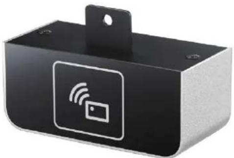
B.7 UTC-510P-R01E
natural_image
Black rectangular electronic device with white wireless signal icon and card symbol (no text or labels)| Interface USB | |||
| Frequency 13.56 MHz | |||
| NFC R/W Mode NFC Type V/2/3/4 | |||
| HF RFID R/W ISO 15693, ISO14443A, ISO14443B | |||
| Support Tag Specification | |||
| Standard Tag Model UID R/W Applications | |||
| NFC Type 2 | NXP NTAG 213/215/216 OK OK Brand protection | ||
| NXP MIFARE® S50/S70 | OK OK Electronic wallet | ||
| NFC Type 3 | Sony FeliCa RCS 919/965/966 | OK OK e-Tickets | |
| NFC Type 4 | NXP MIFARE® DesFire EV1 4K | OK | Personal identification |
| Panasonic MN63Y1213 | OK OK BT and Wi-Fi pairing | ||
| ISO 15693 (NFC Type V) | TI Tag-it Standard/Pro/Plus | OK OK Libraries | |
| ST LRI2K | OK OK Access control | ||
| NXP ICODE SLIX/SLI/SLI-L | OK OK Patrol | ||
| Infineon my-d SRF55V02P | OK OK | Mass transit and event ticketing | |
| Fujitsu/MM89R118/119 | OK | Medical equipment | |
| ST M24LR04/16/64 | OK OK Electronic shelf labelling | ||
| ISO 14443A | NXP MIFARE® Ultralight/Plus X/Plus S | OK | Asset tracking |
| ISO 14443B ST SRIX4K | OK OK e-Purses | ||
| Reading Range | 2 cm ± 1 cm | ||
| OS Support | Windows XP/7/8/Windows 10 IoT Enterprise, Android, Linux | ||
| Dimensions | 90 x 35 x 38 mm/3.57 x 1.37 x 1.49 in | ||
| Operating Temperature | 0 ~ 40 °C/32 ~ 104 °F | ||
B.7.1 Packing List
| Description | Quantity |
| RFID reader module | 1 |
B.7.2 Ordering Information
Part Number Description
UTC-510P-R01E RFID reader for UTC-510 series (USB connection)
B.8 UTC-510P-S01E
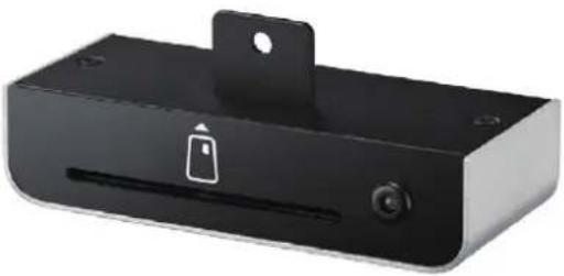
natural_image
Black rectangular electronic device with a lock icon and mounting bracket (no text or symbols visible)| Interface USB (cable length: 50 cm/19.68 in) | |
| Card Acceptor/Reliability | User card friction type (ID-1), 200,000 cycles |
| Card Reader | CPU card, compliant with ISO7816-1,2,3,T=1 and T=0 protocolsMemory card, synchronous 2-line, 3-line and I2C interface |
| LED | Dual-color LED indicatorsCompliant with PC/SC, version 1.0, standards |
| OS Support Windows XP/7/Windows 10 IoT Enterprise | |
| Dimensions 94 x 38 x 22 mm/3.7 x 1.49 x 0.86 in | |
| Operating Temperature | 0 ~ 40 °C/32 ~ 104 °F |
B.8.1 Packing List
| Description Quantity | |
| Smart card reader module | 1 |
B.8.2 Ordering Information
Part Number Description
UTC-510P-S01 Smart card reader for UTC-510 series (USB connection)
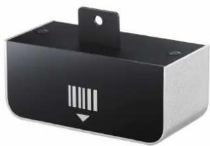
natural_image
Black rectangular electronic device with a barcode symbol on its side (no text or labels visible)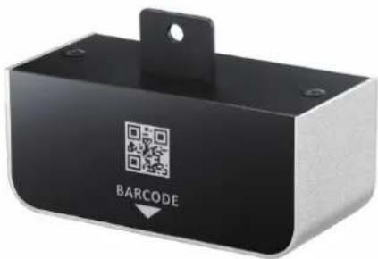
UTC-510P-B01E UTC-510P-B02E
Data Type 1D linear 1D/2D
| Interface USB | ||||
| Performance | Optical System | High-performance linear imaging engine | Image Sensor 752 x 480 CMOS | |
| Print Contrast | 20% minimum reflective difference | Processor | 2D barcode decoder chip 72 MHz | |
| Minimum Resolution | Typical 3 mil (code 39, PCS 0.9) | Illumination | Red LED 625 ± 10 nm | |
| Working Distance *1 | Up to 24" on 100% UPC/EAN symbolsUp to 31.5" on 20 mil code 39 | Reading Precision | ≥ 5 mil | |
| Light Source | 630 nm visible red LED | UPC-A 55 ~ 305 mm (13 mil) | ||
| Scan Rate | Dynamic scanning rate up to 500 scans per second | Depth of Field | 65 ~ 175 mm (6.67 mil);50 ~ 215 mm (10 mil) | |
| Reading Direction | Bi-directional (forwards and backwards) | Data Matrix 50 ~ 220 mm (15 mil) | ||
| QR Code 65 ~ 235 mm (15 mil) | ||||
| Symbol Contrast | ≥ 25% | |||
| Symbologies | Code 39, Code 39 Full ASCII, Code 32, Code 39 Trioptic Code 128,UCC/EAN-128, Codabar, Code 11,Code 93 Standard and Industrial 2 of 5, Interleaved & Matrix 2 of 5 GermanPostal Code, China Postal Code,IATA UPC/EAN/JAN, UPC/EAN/JAN with Addendum Telepen, MSI/Plessey and UK/PlesseyGS1 DataBar (formerly RSS) Linear,Stacked Linear | 2D: PDF417, Data Matrix(ECC200,ECC000,050,080,100,140), QRCode, etc.1D: Code128, EAN-13, EAN-8,Code39, UPC-A, UPC-E, Codabar,Interleaved 2 of 5, ITF-6, ITF-14,ISBN, Code 93, UCC/EAN-128,GS1Databar, Matrix 2 of 5, Code 11,Industrial 2 of 5, Standard 2 of 5,Plessey, MSI-Plessey, etc. | ||
| OS Support Windows 7/8, Windows 10 IoT Enterprise | ||||
| Dimensions 80 x 35 x 38 mm/3.14 x 1.37 x 1.49 in | ||||
| Operating Temperature | 0 ~ 40 °C/32 ~ 104 °F | |||
B.9.1 Packing List
Description Quantity
| Barcode scanner module | 1 |
B.9.2 Ordering Information
Part Number Description
| UTC-510P-B01E 1D barcode scanner for UTC-510 series (USB connection) |
| UTC-510P-B02E 1D/2D barcode scanner for UTC-510 series (USB connection) |
B.10 UTC-510P-M01E
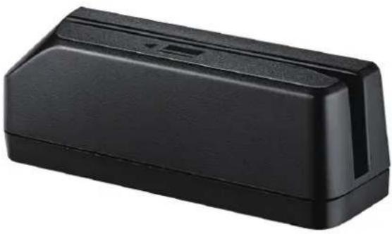
natural_image
Black rectangular electronic component with a small port and slot, no visible text or symbols| Interface USB (cable length: 50 cm/19.68 in) | |
| Track Configuration | TRACK 1/IATA/210 bpi/79 alphanumeric charactersTRACK 2/ABA/75 bpi/40 numeric charactersTRACK 3/thrift/210 bpi/107 numeric characters |
| Card Standard ANSI, ISO, ABA | |
| Read Speed 3 ~ 60 ips (7 ~ 152 cm/s) | |
| Magnetic Head Life | 1,000,000 times (ISO test standard) |
| OS Support Android, Windows 7/XP, Windows 10 IoT Enterprise | |
| Dimensions 94 x 38 x 22 (3.7 x 1.49 x 0.86 in | |
| Operating Temperature | 0 ~ 40 °C/32 ~ 104 °F |
B.10.1 Packing List
| Description Quantity | |
| Magnetic strip reader module | 1 |
B.10.2 Ordering Information
| Part Number Description | |
| UTC-510P-M01E | Magnet strip reader for UTC-510 series (USB connection) |
Appendix C
Touchscreen Options
C.1 Touchscreen Options
| Touchscreen Type | 5-wire analog resistive touch | Projected capacitive touch | Corning® Gorilla® panel with projected capacitive touch |
| Mineral Hardness | 3H 7H 9H | ||
| Impact Test | 510 g steel ball dropped from 50 cm - Pass | 130 g iron ball dropped from 130 cm - Pass | 530 g iron ball dropped from 130 cm - Pass |
| Touch Points Single touch Multi touch Multi touch | |||
| Anti-Microbial No No Yes | |||
| Visible Light Transmission | 80 ±5% 90 ± 2% 90 ± 2% | ||
ADVANTECH
Enabling an Intelligent Planet
www.advantech.com
Please verify specifications before quoting. This guide is intended for reference purposes only.
All product specifications are subject to change without notice.
No part of this publication may be reproduced in any form or by any means, such as electronically, by photocopying, recording, or otherwise, without prior written permission from the publisher.
All brand and product names are trademarks or registered trademarks of their respective companies.
© Advantech Co., Ltd. 2020
- UTC-510/515/520/532/542
- Copyright
- Acknowledgements
- Declaration of Conformity
- FCC Class A
- Warning!
- Packing List
- Technical Support and Assistance
- Warnings
- Contact information
- Manufacturer
- EU Distributor
- Safety Instructions
- Contents
- Chapter 1 General Information ....1
- Chapter 2 System Setup....23
- Chapter 3 Upgrades and Installation....31
- Appendix A Installation Accessories...... 41
- Appendix B UTC Peripherals 47
- Appendix C Touchscreen Options 63
- Chapter 1
- Introduction
- Specifications
- UTC-510
- UTC-510(PoE)
- UTC-515 A/B/C
- UTC-515D/E/F
- UTC-515G
- UTC-520A/B/C
- UTC-520D/E/F
- UTC-520G
- UTC-532A/C
- UTC-532E/F/G
- UTC-542D/F/G
- Dimensions
- UTC-510
- UTC-515
- UTC-520
- UTC-532
- UTC-542
- Chapter 2
- Quick Tour
- Front View
- Rear View
- Side View
- I/O Ports
- UTC-510
- UTC-510(PoE)
- Caution!
- UTC-515
- UTC-520
- UTC-532
- UTC-542
- Setup Procedures
- System Power On
- BIOS Setup
- System Software Installation
- Driver Installation
- Chapter 3
- Introduction
- Installing a 2.5" SATA HDD
- Installing a CFAST Card (A/B Models Only)
- Installing a Memory Module
- Installing a Wireless LAN Card (Optional)
- Installing Peripherals (Optional)
- UTC-510/510(PoE)
- Installing Optional Modules
- UTC-515/520/532
- Panel Mount Installation for UTC-510
- Installing a DRAM Module for UTC-510
- UTC-510
- UTC-510(PoE)
- Installing an SSD Module for UTC-510
- UTC-510
- UTC-510(PoE)
- Installing an mSATA SSD Module for UTC-510
- UTC-510
- UTC-510(PoE)
- Installing a Wi-Fi Module for UTC-510
- UTC-510
- UTC-510(PoE)
- Appendix A
- A.1 Introduction
- A.2 Wall Mount
- UTC-WALL-MOUNT1E
- UTC-WALL-MOUNT2E
- UTC-WALL-MOUNT3E
- VESA 75/100 mm
- A.3 Floor Stand
- UTC-T01-STANDE
- Triangular Floor Stand
- UTC-H01-STANDE
- H-Shape Floor Stand
- Appendix B
- B.1 UTC-P01 (Camera Module)
- B.1.1 Specifications
- B.1.2 Packing List
- B.1.3 Ordering Information
- B.2 UTC-P02 (MSR)
- B.2.1 Specifications
- B.2.2 Packing List
- B.2.3 Ordering Information
- B.3 UTC-P03 (RFID Reader)
- B.3.1 Specifications
- B.3.2 Packing List
- B.3.3 Ordering Information
- B.4 UTC-P06 (Smart Card Reader)
- B.4.1 Specifications
- B.4.2 Packing List
- B.4.3 Ordering Information
- B.5 UTC-P07 (Barcode Reader)
- B.5.1 Specifications
- B.5.2 Packing List
- B.5.3 Ordering Information
- B.6 UTC-P21 (4-in-1 Module)
- B.6.1 Specifications
- B.6.2 Packing List
- B.6.3 Ordering Information
- B.7 UTC-510P-R01E
- B.7.1 Packing List
- B.7.2 Ordering Information
- B.8 UTC-510P-S01E
- B.8.1 Packing List
- B.8.2 Ordering Information
- B.9.1 Packing List
- B.9.2 Ordering Information
- B.10 UTC-510P-M01E
- B.10.1 Packing List
- B.10.2 Ordering Information
- Appendix C
- C.1 Touchscreen Options
- ADVANTECH
- www.advantech.com
Brand : Advantech
Model : UTC-520
Category : Screen