
FPM-3171G - Screen Advantech - Free user manual and instructions
Find the device manual for free FPM-3171G Advantech in PDF.


| Product Type | Industrial LCD Monitor |
| Model | FPM-3171G |
| Display Size | 17" diagonal |
| Display Type | SXGA TFT LCD |
| Max Resolution | 1280 x 1024 |
| Brightness | 350 cd/m² |
| Contrast Ratio | 1000:1 |
| Viewing Angle | 170° (H) / 160° (V) |
| Touchscreen (Optional) | 5-wire analog resistive, RS-232 or USB interface |
| Inputs | VGA (DB-15), DVI-D |
| Power Supply | 100~240 VAC input, +12V / 24V DC output |
| Power Consumption | 35 W max |
| Dimensions (W x H x D) | 482 x 354.8 x 63.9 mm (18.98" x 13.97" x 2.54") |
| Weight | 9.25 kg (20.39 lbs) |
| Enclosure | Stainless steel chassis, aluminum front panel |
| Protection Rating | Front panel NEMA4 / IP65 compliant |
| Mounting Options | Panel, wall, desktop, VESA (75/100 mm), rack (with kit) |
| Operating Temperature | -20°C to 60°C (-4°F to 140°F) |
| Storage Temperature | -30°C to 80°C (-22°F to 176°F) |
| Backlight Lifetime | 50,000 hours |
| Approvals | BSMI, CE, FCC, CCC, UL |
| Warranty | 2 years |
Frequently Asked Questions - FPM-3171G Advantech
User questions about FPM-3171G Advantech
0 question about this device. Answer the ones you know or ask your own.
Ask a new question about this device
Download the instructions for your Screen in PDF format for free! Find your manual FPM-3171G - Advantech and take your electronic device back in hand. On this page are published all the documents necessary for the use of your device. FPM-3171G by Advantech.
USER MANUAL FPM-3171G Advantech
17" SXGA Industrial Monitor with Resistive Touchscreen, Direct-VGA and DVI Ports
User Manual
Copyright
This document is copyrighted by Advantech Co., Ltd. 2005. All rights are reserved. Advantech Co., Ltd. reserves the right to make improvements to the products described in this manual at any time. Specifications are thus subject to change without notice.
No part of this manual may be reproduced, copied, translated, or transmitted in any form or by any means without the prior written permission of Advantech Co., Ltd. Information provided in this manual is intended to be accurate and reliable. However, Advantech Co., Ltd., assumes no responsibility for its use, nor for any infringements upon the rights of third parties which may result from its use.
All brand and product names mentioned herein are trademarks or registered trademarks of their respective holders.
This Manual Covers the Following Models:
FPM-3171G-X0AE 17" SXGA WT Ind. Monitor with VGA, DVI
FPM-3171G-R3AE 17"SVGA WT Ind. Monitor w/Resistive TS (Combo)
Part No. 4th Edition
Printed in Taiwan August 2012
Product Warranty (2 years)
Advantech warrants to you, the original purchaser, that each of its products will be free from defects in materials and workmanship for two years from the date of purchase.
This warranty does not apply to any products which have been repaired or altered by persons other than repair personnel authorized by Advantech, or which have been subject to misuse, abuse, accident or improper installation. Advantech assumes no liability under the terms of this warranty as a consequence of such events.
Because of Advantech's high quality-control standards and rigorous testing, most of our customers never need to use our repair service. If an Advantech product is defective, it will be repaired or replaced at no charge during the warranty period. For out-of-warranty repairs, you will be billed according to the cost of replacement materials, service time and freight. Please consult your dealer for more details.
If you think you have a defective product, follow these steps:
- Collect all the information about the problem encountered. (For example, CPU speed, Advantech products used, other hardware and software used, etc.) Note anything abnormal and list any onscreen messages you get when the problem occurs.
- Call your dealer and describe the problem. Please have your manual, product, and any helpful information readily available.
- If your product is diagnosed as defective, obtain an RMA (return merchandise authorization) number from your dealer. This allows us to process your return more quickly.
- Carefully pack the defective product, a fully-completed Repair and Replacement Order Card and a photocopy proof of purchase date (such as your sales receipt) in a shippable container. A product returned without proof of the purchase date is not eligible for warranty service.
- Write the RMA number visibly on the outside of the package and ship it prepaid to your dealer.
FCC Class A
This equipment has been tested and found to comply with the limits for a Class A digital device, pursuant to Part 15 of the FCC Rules. These limits are designed to provide reasonable protection against harmful interference when the equipment is operated in a residential environment. This equipment generates, uses and can radiate radio frequency energy. If not installed and used in accordance with this user's manual, it may cause harmful interference to radio communications. Note that even when this equipment is installed and used in accordance with this user's manual, there is still no guarantee that interference will not occur. If this equipment is believed to be causing harmful interference to radio or television reception, this can be determined by turning the equipment on and off. If the interference is occurring, the user is encouraged to try to correct the interference by one or more of the following measures:
• Reorient or relocate the receiving antenna
- Increase the separation between the equipment and the receiver
- Connect the equipment to a power outlet on a circuit different from that to which the receiver is connected
- Consult the dealer or an experienced radio/TV technician for help
Additional Information and Assistance
- Visit the Advantech web site at www.advantech.com where you can find the latest information about the product.
- Contact your distributor, sales representative, or Advantech's customer service center for technical support if you need additional assistance. Please have the following information ready before you call:
• Product name and serial number
• Description of your peripheral attachments
- Description of your software (operating system, version, application software, etc.)
• A complete description of the problem
• The exact wording of any error messages
Safety Instructions
- Read these safety instructions carefully.
- Keep this User's Manual for later reference.
- Disconnect this equipment from any AC outlet before cleaning. Use a damp cloth. Do not use liquid or spray detergents for cleaning.
-
For plug-in equipment, the power outlet socket must be located near the equipment and must be easily accessible.
-
Keep this equipment away from humidity.
-
Put this equipment on a reliable surface during installation. Dropping it or letting it fall may cause damage.
-
The openings on the enclosure are for air convection. Protect the equipment from overheating. DO NOT COVER THE OPENINGS.
-
Make sure the voltage of the power source is correct before connecting the equipment to the power outlet.
-
Position the power cord so that people cannot step on it. Do not place anything over the power cord.
-
All cautions and warnings on the equipment should be noted.
-
If the equipment is not used for a long time, disconnect it from the power source to avoid damage by transient overvoltage.
-
Never pour any liquid into an opening. This may cause fire or electrical shock.
-
Never open the equipment. For safety reasons, the equipment should be opened only by qualified service personnel.
-
If one of the following situations arises, get the equipment checked by service personnel:
a. The power cord or plug is damaged.
b. Liquid has penetrated into the equipment.
c. The equipment has been exposed to moisture.
d. The equipment does not work well, or you cannot get it to work according to the user's manual.
e. The equipment has been dropped and damaged.
f. The equipment has obvious signs of breakage.
- DO NOT LEAVE THIS EQUIPMENT IN AN UNCONTROLLED ENVIRONMENT WHERE THE STORAGE TEMPERATURE IS BELOW -30 \~ 80°C (-22 \~ 176°F). THIS MAY DAMAGE THE EQUIPMENT.
The sound pressure level at the operator's position according to IEC 704-1:1982 is no more than 70dB(A).
DISCLAIMER: This set of instructions is given according to IEC 704-1. Advantech disclaims all responsibility for the accuracy of any statements contained herein.
Contents
Chapter 1 Introduction ......2
1.1 Introduction....2
1.2 Specifications .... 3
1.3 LCD Specifications 4
1.4 Power Consumption 4
1.5 Connectors.... 5
1.6 Dimensions.... 6
Figure 1.1:FPM-3171G Dimensions....6
Chapter 2 Mounting......8
2.1 Mounting the Monitor 8
2.1.1 Wall Mounting....8
Figure 2.1: Wall Mounting .... 8
2.1.2 Panel Mounting....9
Figure 2.2:Panel Mounting 9
2.1.3 Rack Mounting 10
Figure 2.3: Rack Mounting.... 10
2.2 Desktop, Swing-ARM Mounting 11
2.2.1 Desktop Stand 11
Figure 2.4: Desktop Stand for the FPM-3171.... 11
2.2.2 Swing-ARM.... 12
Figure 2.5: Swing-ARM for the FPM-3171 ...... 12
Appendix A Touchscreen Installation ....14
A.1 Introduction ...... 14
A.1.1 Resistive Type.... 14
A.2 Resistive Touchscreen Driver Installation 15
A.2.1 Hardware.... 15
A.2.2 Software 16
Appendix B Setting Serial Data for Expansion .....26
B.1 Supported Input Timing Modes 26
Table B.1: Supported Input Formats ...... 26
Appendix C OSD Operation Keypad....28
C.1 OSD Board Overview 28
C.1.1 OSD Button Description.... 28
C.1.2 LED Function 28
C.2 OSD Key Functions 29
C.2.1 Menu Start.... 29
C.2.2 Picture 30
C.2.3 Geometry 31
C.2.4 Color 32
C.2.5 OSD Manager 33
C.2.6 Input Select 34
Appendix D FPM-3171S Dimensions....38
Introduction
Chapter 1 Introduction
1.1 Introduction
Advantech's FPM-3171 Series is a 17" color TFT LCD flat panel monitor built specifically for industrial applications. With the optional touch-screen, the FPM-3171 Series is an excellent and user-friendly system control interface.
In addition to its usual application as an LCD panel monitor, FPM-3171 comes standard with direct VGA and DVI control signal inputs, making it compatible with Industrial PCs and Workstations. Its OSD (Onscreen Display) function allows you to adjust the display factors and turn the backlight on and off for the front view, functions which become critical as more and more industrial HMI users become aware of the benefits of flat panel monitors. FPM-3171G models are equipped with Stainless Steel chassis and NEMA4/IP65 compliant Aluminum front panel. Therefore, FPM-3171S is made of Stainless Steel chassis and NEMA4X/IP65 compliant 316L Stainless Steel front panel.
The FPM-3171 Series has an optional resistive touchscreen. With a resistive touchscreen, the monitor can be immediately transformed into a remote control system.
General
- Construction: Heavy-duty Aluminum and Stainless Steel
- Front panel: Aluminum, NEMA4/IP65 Compliant
• Control: OSD (On Screen Display) control pad on front side - Mounting: Panel, wall, desktop, VESA or rack (with kit)
- Dimensions (W x H x D): 482mm x 354.8mm x 63.9mm (18.98" x 13.97" x 2.54")
• Weight: 9.25 kg (20.39 lbs)
Touchscreen (Optional)
- Type: 5 wire, analog resistive
- Resolution: 4096 x 4096 for resistive model.
• Light transmission: 80% ±5 - Operating Pressure: 30\~45 gram for stylus, contact bounce < 10 ms
- Controller: RS-232 and USB
• Power Consumption: +5 V @ 100 mA - OS Support: Windows XP, Vista, 7, XPe, CE and Linux
- Life Span: Resistive: 35 million activations (typical) at single point with a 5/8" diameter silicone finger at 350g load at 2 touches per sec. Capacitive: 225 million activations (typical) at a single point with a 5/8" diameter silicone finger at 350g load at 2 touches per sec.
1.3 LCD Specifications
- Display type: SXGA TFT LCD
- Display size: 17"
• Max colors: Full color (16.2 million)
• Max resolution: 1280 x 1024 - Dot pitch: 0.264 × 0.264 ~mm
• Viewing Angle: 170^ (H), 160^ (V)
• Luminance: 350 cd/m ^2 - Storage Temperature: -30 80^ C (-22 \~ 176°F)
- Operating Temperature: -20 60^ C ( -4 140^ F )
- Backlight Lifetime: 50,000 hrs
- Contrast Ratio: 1000:1
1.4 Power Consumption
• Max. Output Power: 35W +20%
• AC Input Voltage: 100\~240VAC
• Output Voltage: +12V 4.7A
• Safety Standards: BSMI, CE, FCC, CCC, UL
The following connectors are situated on the left hand side of the FPM-3171 Series:
VGA Port (DB-15)
This DB-15 connector can be connected to the system via the external 15-pin DB-15 connector thru the I/O from this unit.
DVI Port (DVI-D)
Connected with a standard DVI connector thru I/O port of this unit. Only supports digital signals
Touchscreen Connector (DB-9)
This connector will be present only if a touchscreen is installed. It must be connected to the RS-232 port of the PC. The touchscreen cable is included with all orders which include the RS-232 touchscreen option.
Touchscreen Connector (USB)
This connector will be present only if a touchscreen is installed. It must be connected to the USB port of the PC. The touchscreen cable is included with all orders which include the USB touchscreen option.
Note: RS-232 & USB touchscreen interface does not allow connection into the system at the same time, but it can be changed via switch
DC 12V or DC 24V Power In
This connector connects to the DC 12V / 24V Switching Power Supply.
![CUTOIT [IYEN3DN447.5X329.510 387,20 [1,286]](/content/2026/05/818839/images/3e52e9a7159a3c3a9cc5536621ba318cdc545b4d6e087497e3cafaac786e6495.jpg)
Figure 1.1: FPM-3171G Dimensions
Mounting
Chapter 2 Mounting
2.1 Mounting the Monitor
The FPM-3171 Series can be placed as you require. The versatility of the FPM-3171 mounts enable it to be mounted on your desk or anywhere else.
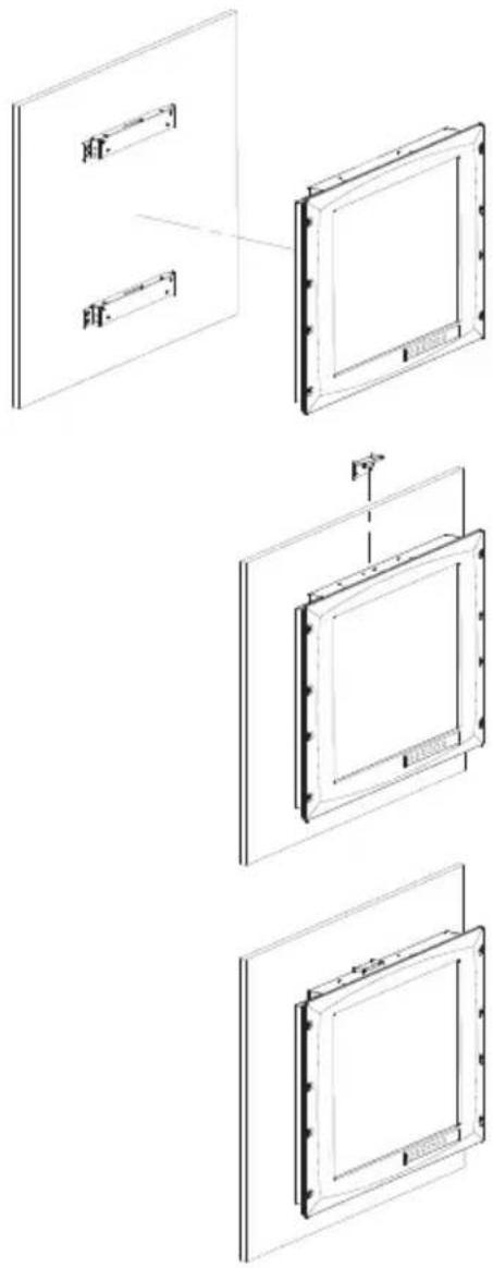
2.1.1 Wall Mounting
With wall brackets, the FPM-3171 can be mounted directly to a wall.
If you need to install the FPM-3171 in different ways, release the mounting brackets by detaching the four screws on the rear side.
natural_image
Technical line drawings of a rectangular panel assembly with mounting holes and mounting brackets (no text or symbols)Figure 2.1: Wall Mounting
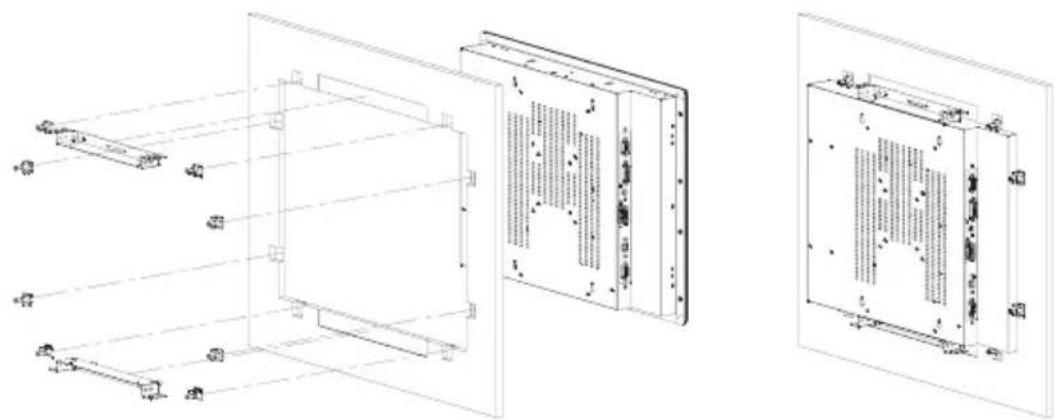
2.1.2 Panel Mounting
If you need to install the FPM-3171 series on a panel mount, please release the mounting brackets by detaching four screws on rear side and fix them on up and bottom side by screws.
natural_image
Technical line drawings of a server rack unit with internal components and mounting brackets (no text or symbols)Figure 2.2: Panel Mounting (Cutout Dimensions: 447.5x329.5)
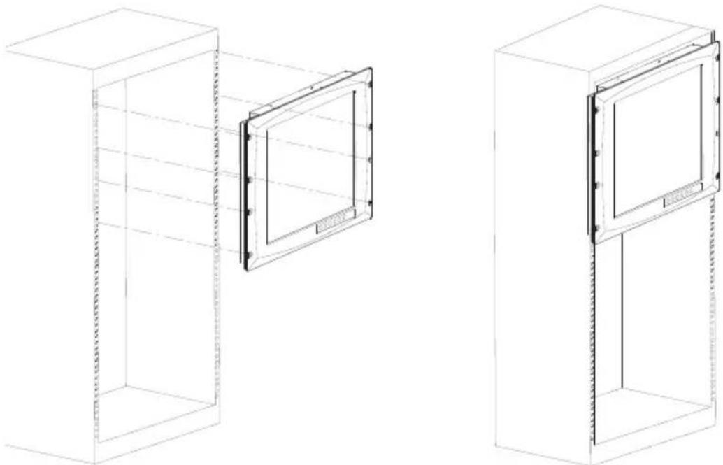
2.1.3 Rack Mounting
FPM-3171G series products could be directly mount to the industrial standard 19" rack. There are four screw holes on each side of the panel.
natural_image
Technical line drawing of two 3D cabinet or enclosure structures with internal grilles and mounting brackets (no text or symbols)Figure 2.3: Rack Mounting
2.2 Desktop, Swing-ARM Mounting
The FPM-3171 Series can be mounted in other ways. You can place the desktop stand for desktop use or attach it on a swing-arm bracket.
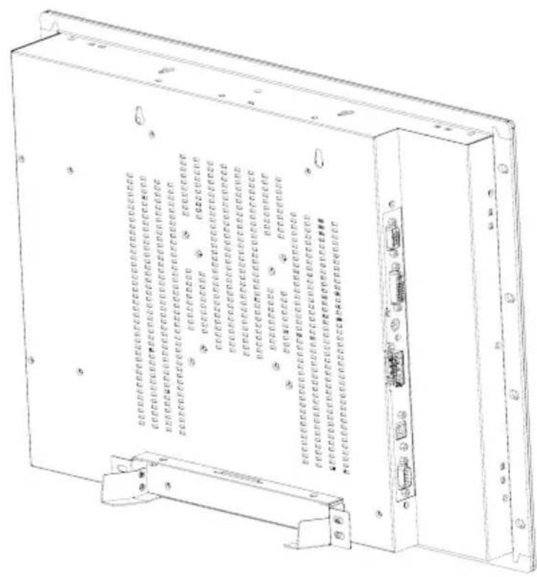
2.2.1 Desktop Stand
The desktop stand brackets are attached to the rear of FPM-3171.
natural_image
Technical line drawing of a rectangular electronic device with ports and connectors (no text or symbols)Figure 2.4: Desktop Stand for the FPM-3171
2.2.2 Swing-ARM
Detach the mounting brackets on the rear side, then attach the FPM-3171 series onto the Swing-ARM mount (75mm or 100mm square bracket).
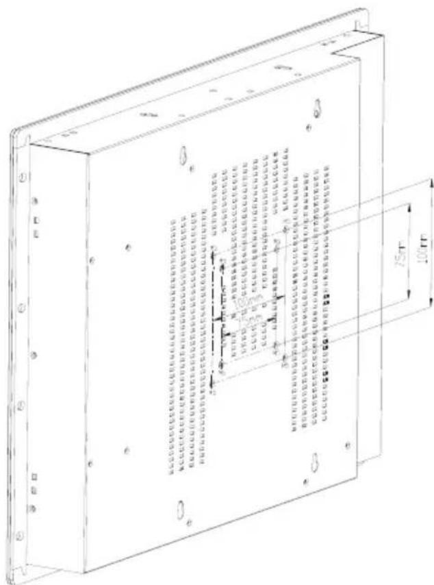
Figure 2.5: Swing-ARM for the FPM-3171
Touchscreen Driver Installation
Appendix A Touchscreen Installation
A.1 Introduction
The FPM-3171 Series' optional touchscreens uses 5-wire resistive technology. They provide more accurate sensing capacity than other technologies. The touchscreen is specially designed for tough industrial environments, and has been approved to FCC Class A.
Note: RS-232 & USB touchscreen interface does not allow connection to the system at the same time. It can be changed by switch.
A.1.1 Resistive Type
Supply Voltage and Current
- +5Vdc , nominal (+4.50VDC to +5.25VDC) Self powered only.
- 50 mA standby, typical at +5 Vdc; during touch 160 mA average, 240 mA peak
• Average power dissipation is 0.5 W, typical. - Supply must be capable of sourcing 400 mA, minimum.
- Total noise and ripple requirement must be less than 100 mV (p-p) for frequencies below 1 MHz, and less than 50 mV (p-p) for frequencies above 1 MHz.
Serial Interface
- EIA 232E (Serial RS-232), DCE configuration. 8 Data Bits, 1 Stop Bit, No Parity, Full Duplex.
- Hardware handshaking: RTS/CTS.
- DSR is pulled HIGH (> + 3V) by the touch screen control board when connected and powered. DTR can be asserted by the host to interrupt the flow of data from the controller. Note that if the application does not monitor CTS, then an interval of approximately 5 seconds should be inserted between the issuance of a reset command and any other command.
Communication Parameters
• Baud Rate 9600 (default), and 17200 bps
- 8 Data bits, 1 stop bit, no parity only.
Interface - USB
Conforms to USB Revision 1.1. If the USB is connected to the controller, the controller will communicate over the USB, and will not communicate over the serial port. The touch screen control board is never powered from the USB – it is self-powered only.
Operating Modes
Full AccuTouch SmartSet protocol. Emulation of E281A-4002 protocol can be selected by SmartSet command.
Initial/ Stream/ Untouch/ Z-axis Enable Modes.
Touch Resolu tion: 4096x4096, size independent.
Conversion Time: Approximately 10 ms per coordinate set.
A.2 Resistive Touchscreen Driver Installation
A.2.1 Hardware
Touchscreen controllers must be configured for the driver prior to installation. Elo typically ships controllers in a default setup that is compatible with this driver. Controller requirements are:
Serial
Serial controllers must conform to these minimum requirements:
• Baud rate-9600 baud.
• Data format-SMARTSET
- It is desirable for a full handshaking connection to be established between the touchscreen controller and the computer, but it is not required. The controller will function with this driver in a "two-wire", Receive Data and Ground (RxD and Gnd) configuration. The consequences of a two-wire connection are:
+ Automatic detection of the controllers on serial ports during setup is not possible
+ Controller information will not be registered in the Property Page of the Control Panel
USB
* USB controllers require no configuration prior to installation.
* Elo's USB controllers are Human Interface Device (HID) compliant. The Windows XP operating systems have native HID drivers that provide low-level support for Elo touchscreen controllers. An Elo touch-monitor with a USB touchscreen controller installed will provide the following limited operation with these native HID drivers. Operation of the controller will be limited without the installation of the software discussed in the next section:
- The mouse cursor will move on the display in response to touch
- The direction of motion on the display will depend on the orientation of the touchscreen and the defaults programmed into the controller and the driver
- No "beep" will be heard when the screen is touched
- No Control Panel application is available to configure the operation of the driver.
A.2.2 Software
There are many options to consider when installing the driver files. This section will explain the most common ways that the driver is installed. Consult Elo Applications Engineering for situations not covered in this section.
Setup from Windows Desktop
For WinXP OS please execute:
CDROM: TouchScreen-DRV\ELO Touch Driver\Windows Drivers\Windows XP-7-Vista SW601379_TETouch_5.2.0.exe
Single monitor, serial controller
-
Run the self-extracting zip file to unzip the files, using the Run EloSetup option
-
EloSetup will launch. Check the "Install Serial Touchscreen Drivers" box.
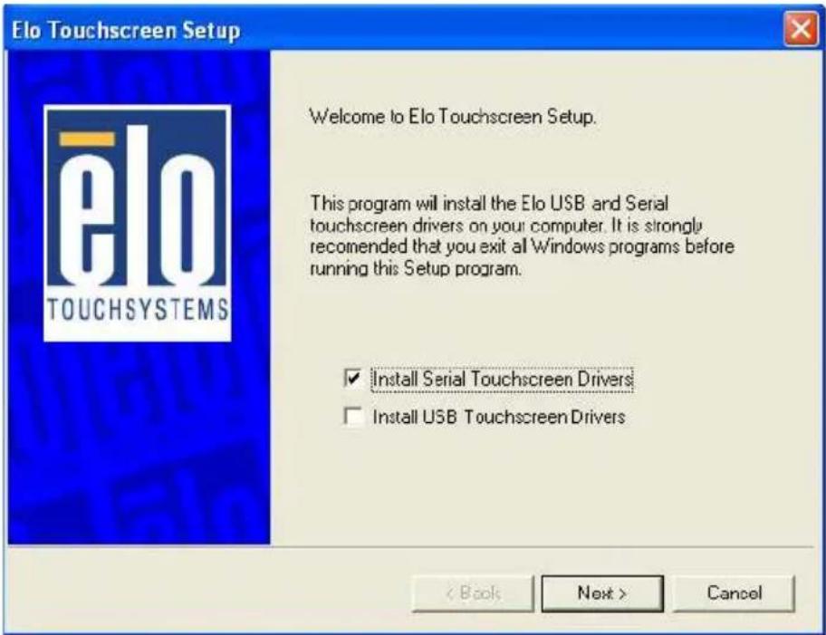
- Review and accept the License Agreement
- Check “Auto-detect Elo devices” if your touchmonitor serial cable is connected to the computer and the serial cable supports hardware handshaking. If you connect the serial cable later, do not check the “auto-detect” box. Go to the next screen.
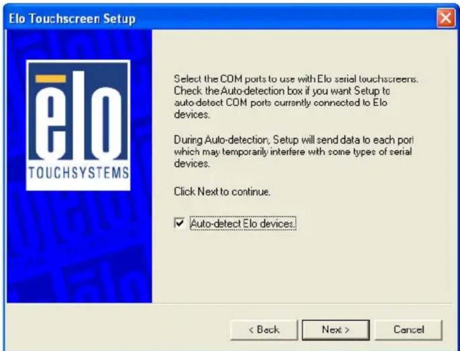
17 Appendix A
-
A list of all the serial ports that the system detected is shown. If you checked the auto-detect box in the previous screen, and your touch-monitor serial cable is attached to the computer, the COM port that you selected should be checked in the list. If you agree with the selection, click Next and proceed to the next screen.
-
The COM port you selected will be shown in the window of this screen. This is your last opportunity to change your COM port selection before the driver files are installed. Use the Back button(s) to change any of the selections you previously made. Click "Next" to complete the installation of the driver files.
-
Depending on the revision of the driver you are installing, Windows may advise you that the “software you are installing has not passed Windows logo testing...”. Select “Continue Anyway” to proceed with the installation. This message can be suppressed in future installations by changing the selection in “Driver Signing Options” at Control Panel>System>Hardware>Device Manager>Driver Signing.
-
When the “Setup Complete” screen appears, you may choose to run calibration the (Elo Video Alignment program, EloVA) immediately or wait until later. If you choose not to run this program now, you can run it from the Elo Control Panel application.
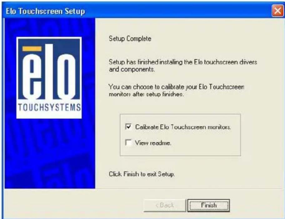
Single monitor, USB controller
- Run the self-extracting zip file to unzip the files, using the Run EloSetup option.
- EloSetup will launch. Check the “Install USB Touchscreen Drivers” box.
- Review and accept the License Agreement.
- The driver files will install. When the “Setup Complete” screen appears, you may choose to run calibration (the Elo Video Alignment program, EloVA) immediately or wait until later. If you choose not to run this program now, you can run it from the Elo Control Panel application.
Multiple monitors, serial controllers
- Follow the general procedure for Single monitor, serial controller installation above, auto detecting or selecting all the serial ports that you will use.
- The driver files will install. When the “Setup Complete” screen appears, you may choose to run calibration (the Elo Video Alignment program, EloVA) immediately or wait until later. If you choose not to run this program now, you can run it from the Elo Control Panel application. When EloVA runs for the first time, it will attempt to calibrate all controllers and/or serial ports that were installed. Press the Esc key on the keyboard to terminate or skip calibration for any monitor, or allow the program to time out (as indicated by the progress bar reaching maximum).
Multiple monitors, USB controllers
- Follow the procedure for Single monitor, USB controller installation above.
- The driver files will install. When the “Setup Complete” screen appears, you may choose to run calibration (the Elo Video Alignment program, EloVA) immediately or wait until later. If you choose not to run this program now, you can run it from the Elo Control Panel application. When EloVA runs for the first time, it will attempt to calibrate all controllers and/or serial ports that were installed. Press the Esc key on the keyboard to terminate or skip calibration for any monitor, or allow the program to time out (as indicated by the progress bar reaching maximum). The program will continue until all controllers and/or ports have been calibrated.
Multiple monitors, serial and USB controllers
-
Run the self-extracting zip file to unzip the files, using the Run EloSetup option
-
EloSetup will launch. Check both the “Install Serial Touchscreen Drivers” and “Install USB Touchscreen Drivers” boxes.
-
Review and accept the License Agreement
-
The program will appear to proceed as a single/multiple serial controller installation but USB files will also install.
-
The driver files will install. When the “Setup Complete” screen appears, you may choose to run calibration (the Elo Video Alignment program, EloVA) immediately or wait until later. If you choose not to run this program now, you can run it from the Elo Control Panel application. When EloVA runs for the first time, it will attempt to calibrate all controllers and/or serial ports that were installed. Press the Esc key on the keyboard to terminate or skip calibration for any monitor, or allow the program to time out (as indicated by the progress bar reaching maximum). The program will continue until all controllers and/or ports have been calibrated.
Silent Install
The EloSetup program for this driver may also be run as an attended or unattended program from a command line, batch file, etc. Example usage:
To Silent install for USB controllers use
EloSetup /iu /s
To Silent install for a Serial controller on COM1 use
EloSetup /is /P:1 /s
To view all the options available for this installation method, run EloSetup as EloSetup /h.
![EloSetup Parameters ELOSETUP [/S] [/U] [/Iu] [/Is] [/P:,...] [/A]] [/C[]] [/H | ?] /S Silent Install /U Uninstall /Iu Install USB drivers /Is Install Serial drivers /P Install for specified Serial Com Ports Port number(s) of Elo Serial devices e.g: ELOSETUP /Is /P:1,2 where 1 is COM1 and 2 is COM2 /A Perform auto-detection of serial com ports /C Run either EloCust.exe or optional provided after installation /H Display options /? Display options OK](/content/2026/05/818839/images/034a3d0e7104d93fae23f598ce8f5d7c12a06a2bf2ade553a865e40fc0c2aa4b.jpg)
- Adding Additional Serial Controllers
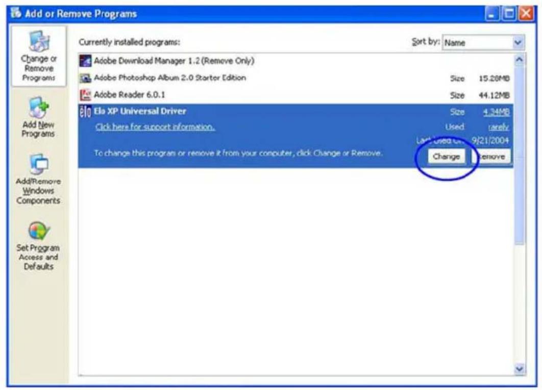
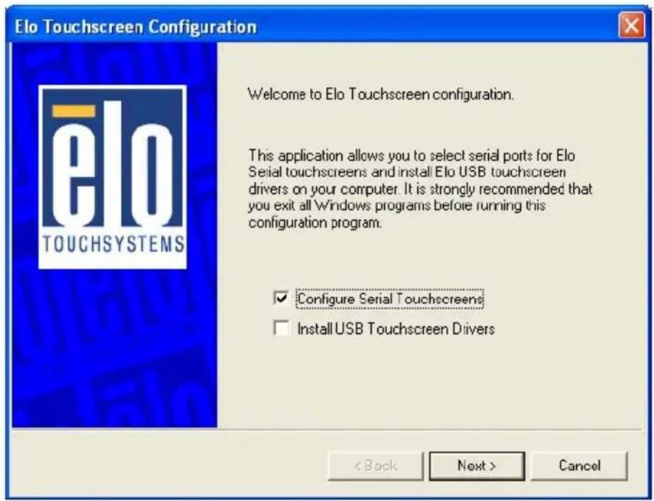
Click on the Change option from the Add/Remove programs in the Control Panel, Elo entry.
- Change Serial Port
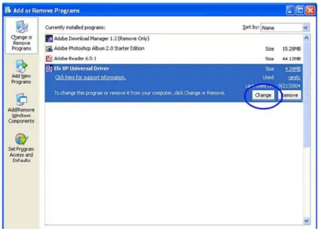
To change Serial port click on the Change option from the Add/Remove programs in the Control Panel, Elo entry.
- Adding Additional USB Controllers
If there are Elo USB devices already installed, plug the USB cable from the touchmonitor into the computer and run EloVA to calibrate the touch-monitors.
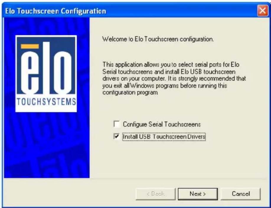
If there are no Elo USB devices attached to the system, click on the Change option from the Add/Remove programs in the Control Panel, Elo entry.
Setting Serial Data for Expansion
Appendix B Setting Serial Data for Expansion
B.1 Supported Input Timing Modes
The different frequencies below are already programmed in this module, and the synchronous signal inputs are automatically recognized.
| Table B.1: Supported Input Formats | |||||
| Vertical Frequencies | |||||
| Resolution | 56 Hz 60 Hz | 70 Hz 72 Hz | 75 Hz | ||
| 640 x 480 Yes | Yes Yes Yes | ||||
| 720 x 400 Yes | |||||
| 800 x 600 Yes | Yes Yes Yes | Yes | |||
| 1024 x 768 Yes | Yes Yes Yes | ||||
| 1280*1024 Yes | Yes Yes Yes | ||||
Note 1: Even if the preset timing is entered, some adjustment of functions such as Horizontal period, CLK-delay and display position, are required. The adjusted values are memorized in every preset number.
Note 2: This module recognizes the synchronous signals with near preset timing of the frequency of the HS and Vsync, even in the case that the signals other than the preset timing that were entered.
Note 3: Because adjustments may not fit, such as differing magnifying ratios or, in the case that you use it except for the display timing that was preset.
OSD Operation Keypad
Appendix C OSD Operation Keypad
C.1 OSD Board Overview

C.1.1 OSD Button Description
| Buttons Descriptions | |
| Source Changes input video source | |
| Menu/Sel Activate the OSD menu | |
| Enter /confirm the selected option | |
| Left/ | Activate volume control. |
| Decrease | Move the selector to the previous option |
| Arrow | Decrease the gauge value of the selected option |
| Brightness can be decreased by left button. | |
| Right/ | Activate the volume control. |
| Increase | Move the selector to the next option |
| Arrow | Increase the gauge value of selected option. |
| Brightness can be increased using the right button. | |
| Auto/Exit Automatically adjust the closck, phase, H-position and V-position. | |
| Exit menu | |
| Power Turn the monitor ON and OFF | |
C.1.2 LED Function
| On | Green |
| StandBy/Off | Green Blinking |
| No Signals | Orange |
C.2 OSD Key Functions
Each selected value is stored into LCD memory after SEL signal input or time out. The stored values are not affected if the power is turned off. But the selected value is not available in case a selected mode is changed before time out or power is turned off before time out. TIME OUT 5-6 seconds (Can be set in OSD Manager) The default definition of input keys is shown as following:
C.2.1 Menu Start
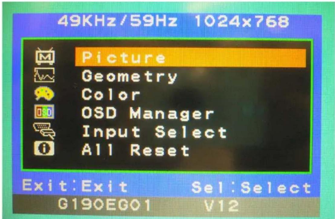
Generate Main Menu
Press MENU Button in OSD function key
- Main Menu
• Available Key Functions
 | N/A |  | N/A |
 | Select to exit menu or wait for time out |  | N/A |
 | N/A |  | N/A |
C.2.2 Picture
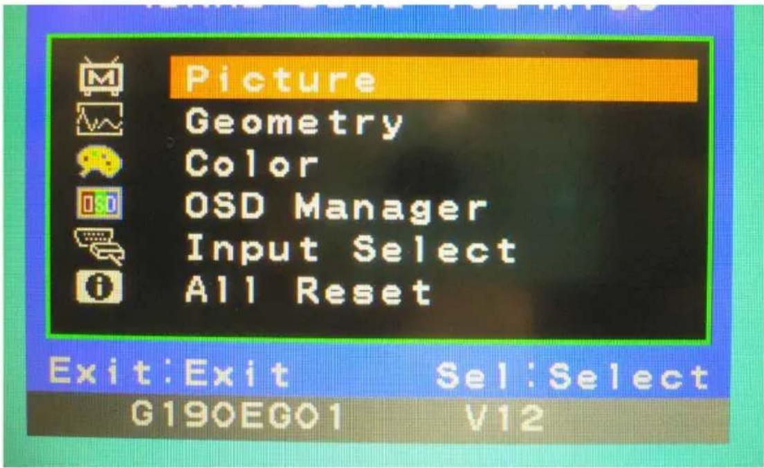
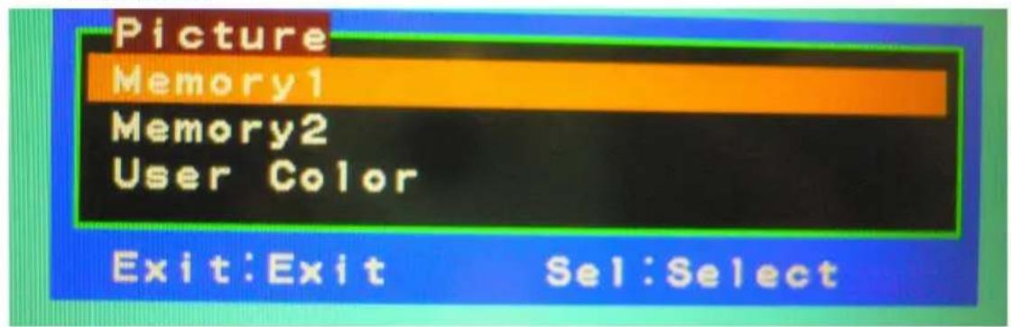
Select by Left and Right Button, press Menu Button for selection Confirmation
- Main Menu
- Sub-Menu
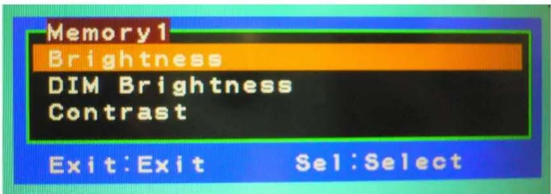
• Available Key Functions

Power off the LCD monitor

Decrease the gauge value of the selected option
Return to last menu Selected to confirm

Increase the gauge value of the selected option

N/A
C.2.3 Geometry
- Main Menu
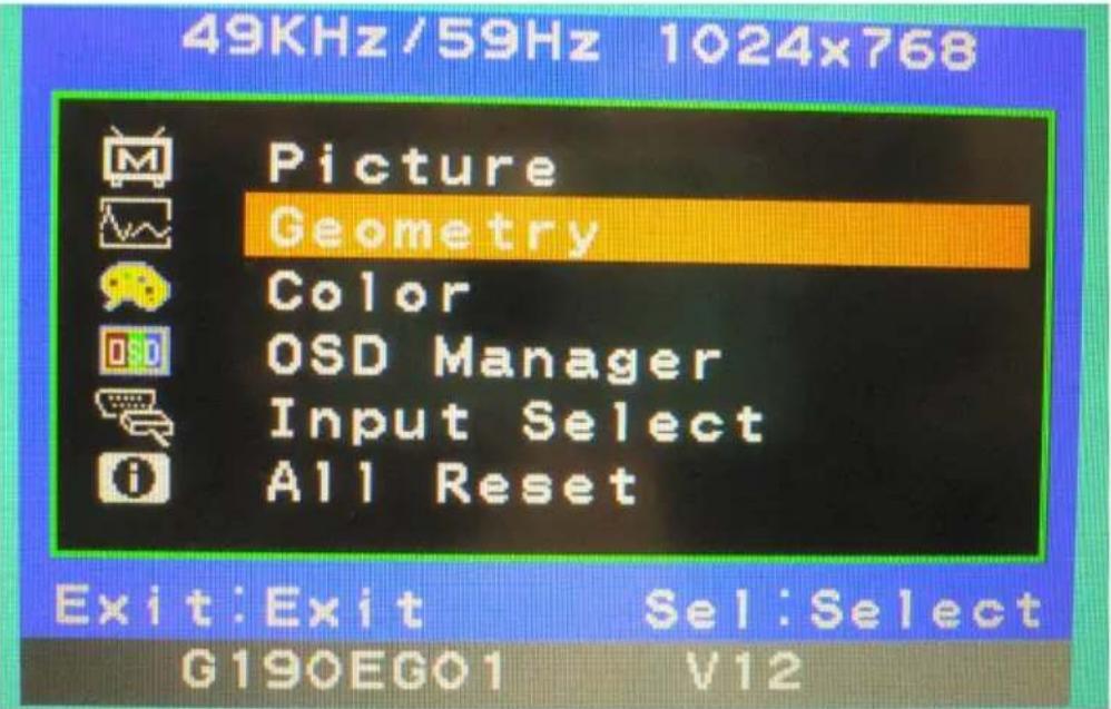
- Sub-Menu
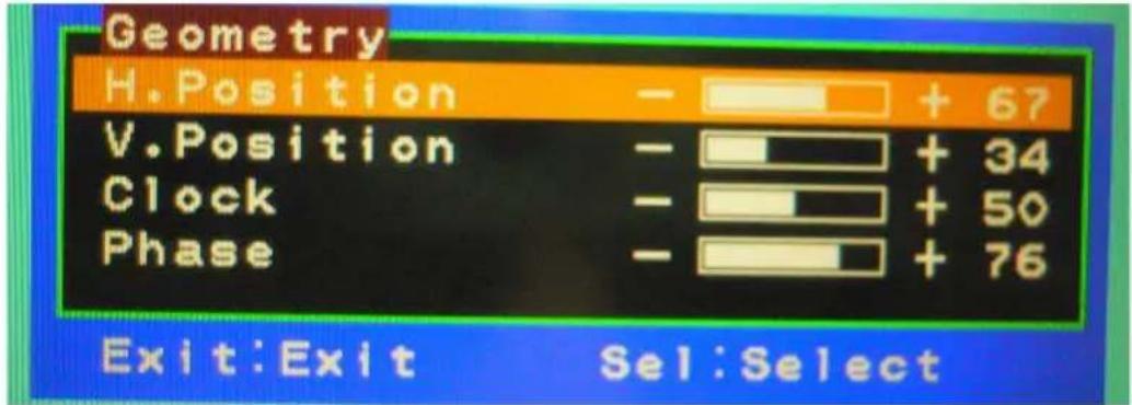
• Available Key Functions
Power off the LCD monitor

Decrease the gauge value of the selected option
Return to last menu Selected to confirm

Increase the gauge value of the selected option

N/A
C.2.4 Color
- Main Menu
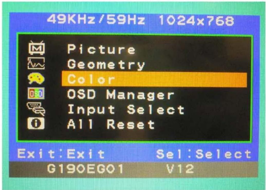
- Sub-Menu
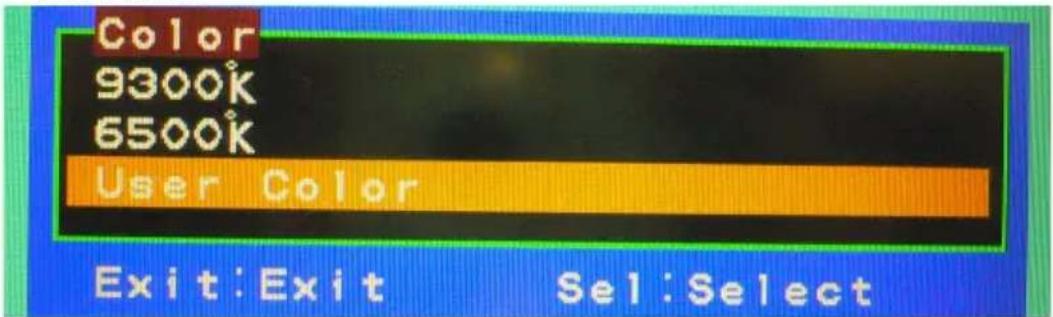
• Available Key Functions

Power off the LCD monitor

Decrease the gauge value of the selected option
Return to last menu Selected to confirm

Increase the gauge value of the selected option

N/A
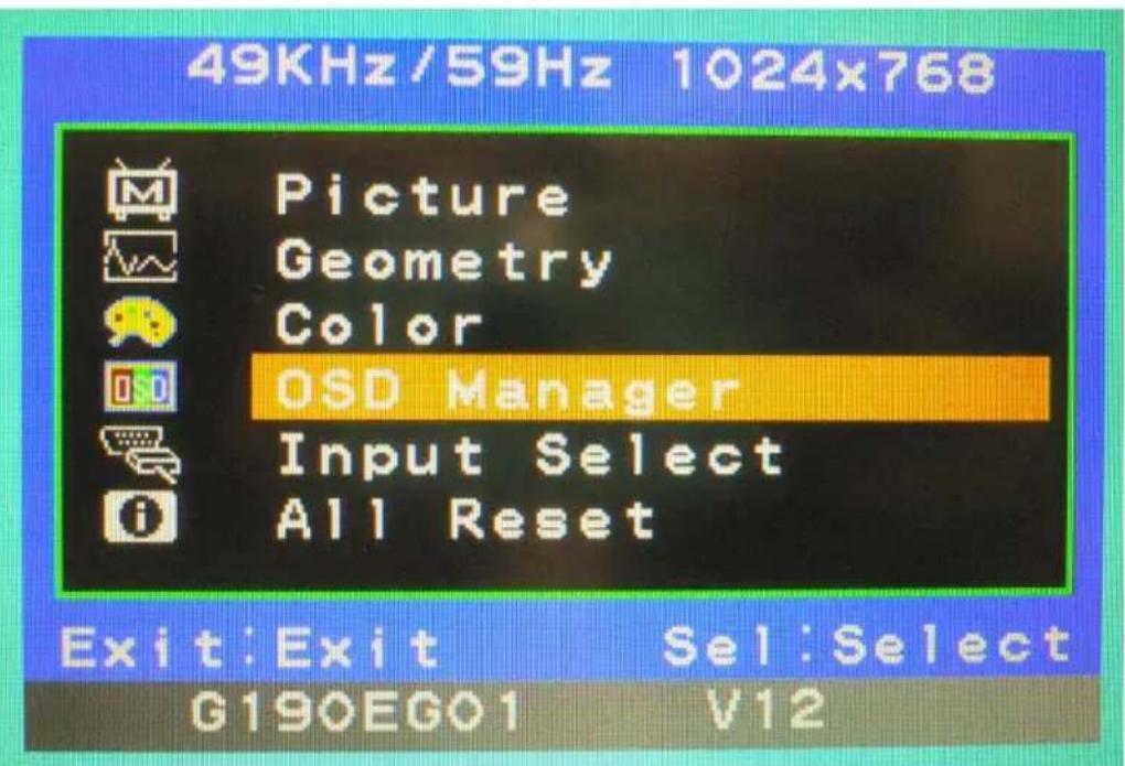
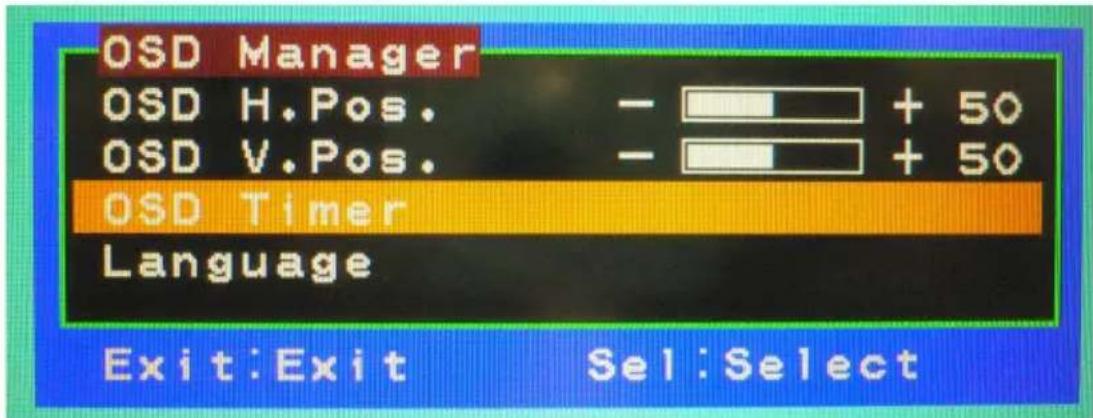
C.2.5 OSD Manager
- Main Menu
- Sub-Menu
• Available Key Functions

Power off the LCD monitor

Decrease the gauge value of the selected option

Return to last menu Selected to confirm

Increase the gauge value of the selected option

N/A
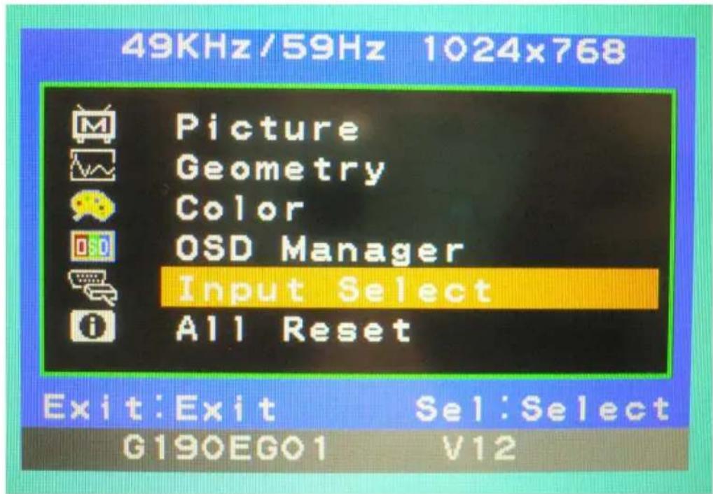
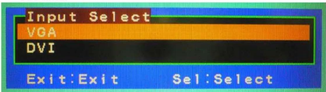
C.2.6 Input Select
- Main Menu
- Sub-Menu
• Available Key Functions

Power off the LCD monitor

Decrease the gauge value of the selected option

Return to last menu Selected to confirm

Increase the gauge value of the selected option

N/A
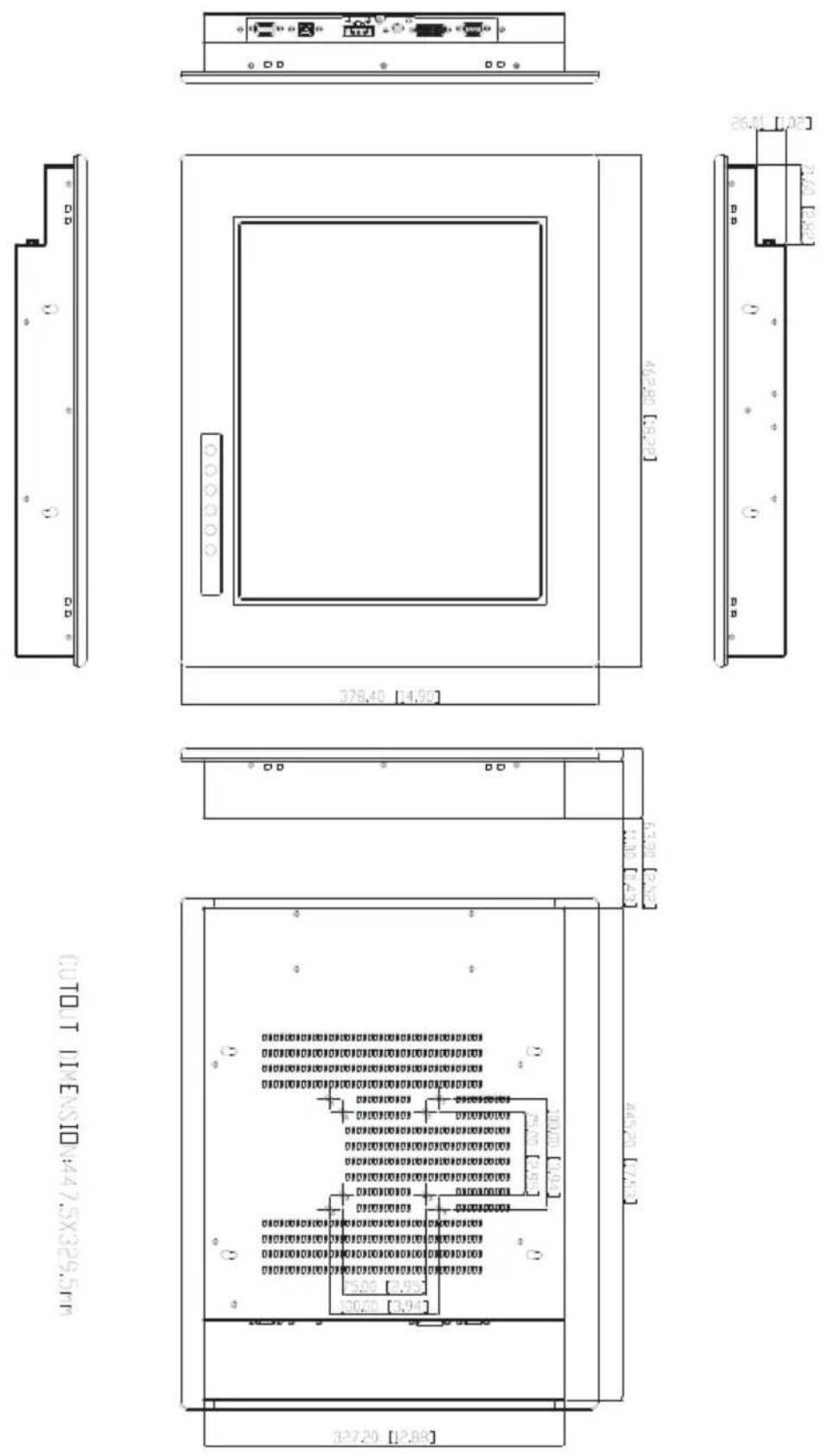
FPM-3171S Dimensions
Appendix D FPM-3171S Dimensions
- User Manual
- Copyright
- Product Warranty (2 years)
- FCC Class A
- Additional Information and Assistance
- Safety Instructions
- Contents
- Chapter 1 Introduction ......2
- Chapter 2 Mounting......8
- Appendix A Touchscreen Installation ....14
- Appendix B Setting Serial Data for Expansion .....26
- Appendix C OSD Operation Keypad....28
- Appendix D FPM-3171S Dimensions....38
- Introduction
- Chapter 1 Introduction
- Introduction
- General
- Touchscreen (Optional)
- LCD Specifications
- Power Consumption
- VGA Port (DB-15)
- DVI Port (DVI-D)
- Touchscreen Connector (DB-9)
- Touchscreen Connector (USB)
- DC 12V or DC 24V Power In
- Mounting
- Chapter 2 Mounting
- Mounting the Monitor
- Wall Mounting
- Panel Mounting
- Rack Mounting
- Desktop, Swing-ARM Mounting
- Desktop Stand
- Swing-ARM
- Touchscreen Driver Installation
- Appendix A Touchscreen Installation
- A.1 Introduction
- A.1.1 Resistive Type
- Supply Voltage and Current
- Serial Interface
- Communication Parameters
- Interface - USB
- Operating Modes
- A.2 Resistive Touchscreen Driver Installation
- A.2.1 Hardware
- Serial
- USB
- A.2.2 Software
- Setup from Windows Desktop
- Multiple monitors, USB controllers
- Multiple monitors, serial and USB controllers
- Silent Install
- Setting Serial Data for Expansion
- Appendix B Setting Serial Data for Expansion
- B.1 Supported Input Timing Modes
- OSD Operation Keypad
- Appendix C OSD Operation Keypad
- C.1 OSD Board Overview
- C.1.1 OSD Button Description
- C.1.2 LED Function
- C.2 OSD Key Functions
- C.2.1 Menu Start
- C.2.2 Picture
- C.2.3 Geometry
- C.2.4 Color
- C.2.5 OSD Manager
- C.2.6 Input Select
- FPM-3171S Dimensions
- Appendix D FPM-3171S Dimensions
Brand : Advantech
Model : FPM-3171G
Category : Screen