
DS-980GL - Media player Advantech - Free user manual and instructions
Find the device manual for free DS-980GL Advantech in PDF.


| Product Type | Video Wall Signage Player |
| Brand | Advantech |
| Model | DS-980GL |
| CPU | Intel Core i7-6700TE / i5-6500TE / i3-6100TE / Celeron G3900TE (LGA 1151, TDP up to 35W) |
| Chipset | Intel Q170 |
| Graphics | Intel HD Graphics 530 |
| Memory | 2 x DDR4 2133MHz SO-DIMM, max 32GB (16GB per DIMM) |
| Storage | 2 x 2.5" SATA III (RAID 0/1); optional mSATA via mini-PCIe |
| Display Outputs | 3 x HDMI (1 x HDMI2.0, 2 x HDMI1.4); max resolution 4096x2160 @60Hz |
| Expansion Slot | 1 x PCI Express x16 (supports optional graphics card for up to 6 outputs) |
| Audio | S/PDIF, Line-Out, Mic-In |
| LAN | 2 x Gigabit Ethernet (Intel I219 & I211) |
| USB | 4 x USB 3.0, 2 x USB 2.0 |
| COM | 1 x RS-232 / 2 x RS-485/422 (with extension cable) |
| Dimensions (Light) | 250 x 190 x 53 mm |
| Weight (Light) | 3.1 kg |
| Power Input | 12V DC-in, 150W adapter included |
| Operating Temperature | 0°C to 45°C |
| Storage Temperature | -40°C to 85°C |
| Operating System | Windows 7 (64/32bit), 8.1 (64bit), 10 (64bit) |
| Certifications | UL, CB, BSMI, CCC, CE, FCC Class B |
| Warranty | 2 years |
| Maintenance | Disconnect from AC before cleaning. Use damp cloth only. Do not use liquid detergents. |
| Safety | Keep away from humidity. Do not cover openings. Use correct voltage. Do not open equipment. Storage -20°C to 60°C. |
Frequently Asked Questions - DS-980GL Advantech
User questions about DS-980GL Advantech
0 question about this device. Answer the ones you know or ask your own.
Ask a new question about this device
Download the instructions for your Media player in PDF format for free! Find your manual DS-980GL - Advantech and take your electronic device back in hand. On this page are published all the documents necessary for the use of your device. DS-980GL by Advantech.
USER MANUAL DS-980GL Advantech
natural_image
Illustration of four electronic circuit boards with white outlines on a purple background (no text or symbols)DS-980/DS-980GL
Video Wall Signage Player by Expandable PCI Express x16
Copyright
The documentation and the software included with this product are copyrighted 2016 by Advantech Co., Ltd. All rights are reserved. Advantech Co., Ltd. reserves the right to make improvements in the products described in this manual at any time without notice. No part of this manual may be reproduced, copied, translated or transmitted in any form or by any means without the prior written permission of Advantech Co., Ltd. Information provided in this manual is intended to be accurate and reliable. However, Advantech Co., Ltd. assumes no responsibility for its use, nor for any infringements of the rights of third parties, which may result from its use.
Acknowledgements
Award is a trademark of Award Software International, Inc.
IBM, PC/AT, PS/2 and VGA are trademarks of International Business Machines Corporation.
Intel® and Celeron® are trademarks of Intel Corporation.
Microsoft Windows® is a registered trademark of Microsoft Corp.
AMI is a registered trademark of American Megatrends Inc.
ESS is a trademark of ESS Technology, Inc.
UMC is a trademark of United Microelectronics Corporation.
SMI is a trademark of Silicon Motion, Inc.
Creative is a trademark of Creative Technology LTD.
CHRONTEL is a trademark of Chrontel Inc.
All other product names or trademarks are properties of their respective owners.
For more information about this and other Advantech products, please visit our website
at: http://www.advantech.com/
For technical support and service, please visit our support website at:
http://support.advantech.com.tw/support/
Part No. 2006098010 Edition 1
Printed in Taiwan September 2016
Product Warranty (2 years)
Advantech warrants to you, the original purchaser, that each of its products will be free from defects in materials and workmanship for two years from the date of purchase.
This warranty does not apply to any products which have been repaired or altered by persons other than repair personnel authorized by Advantech, or which have been subject to misuse, abuse, accident or improper installation. Advantech assumes no liability under the terms of this warranty as a consequence of such events.
Because of Advantech's high quality-control standards and rigorous testing, most of our customers never need to use our repair service. If an Advantech product is defective, it will be repaired or replaced at no charge during the warranty period. For out-of-warranty repairs, you will be billed according to the cost of replacement materials, service time and freight. Please consult your dealer for more details.
If you think you have a defective product, follow these steps:
- Collect all the information about the problem encountered. (For example, CPU speed, Advantech products used, other hardware and software used, etc.) Note anything abnormal and list any onscreen messages you get when the problem occurs.
- Call your dealer and describe the problem. Please have your manual, product, and any helpful information readily available.
- If your product is diagnosed as defective, obtain an RMA (return merchandise authorization) number from your dealer. This allows us to process your return more quickly.
- Carefully pack the defective product, a fully-completed Repair and Replacement Order Card and a photocopy proof of purchase date (such as your sales receipt) in a shippable container. A product returned without proof of the purchase date is not eligible for warranty service.
- Write the RMA number visibly on the outside of the package and ship it prepaid to your dealer.
Technical Support and Assistance
- Visit the Advantech website at http://support.advantech.com where you can find the latest information about the product.
- Contact your distributor, sales representative, or Advantech's customer service center for technical support if you need additional assistance. Please have the following information ready before you call:
– Product name and serial number
– Description of your peripheral attachments
– Description of your software (operating system, version, application software, etc.)
– A complete description of the problem
– The exact wording of any error messages
Warnings, Cautions and Notes
Warning! Warnings indicate conditions, which if not observed, can cause personal injury!

Caution! Cautions are included to help you avoid damaging hardware or losing data. e.g.

There is a danger of a new battery exploding if it is incorrectly installed. Do not attempt to recharge, force open, or heat the battery. Replace the battery only with the same or equivalent type recommended by the manufacturer. Discard used batteries according to the manufacturer's instructions.
Note! Notes provide optional additional information.

Battery Information
Batteries, battery packs, and accumulators should not be disposed of as unsorted household waste. Please use the public collection system to return, recycle, or treat them in compliance with the local regulations.
Caution! Batteries are at risk of exploding if incorrectly installed. Replace only with the same or equivalent type recommended by the manufacturer. Discard used batteries according to the manufacturer's instructions.

Packing List
Before installation, please ensure the following items have been shipped:
■ 1 x DS-980/DS-980GL system
■ 1 x 12V DC-in 150W power adaptor
■ 1 x accessory box containing the items listed below
- 1 x Signage Software (WISE-PaaS/RMM & WebAccess/IMM) CD package
- 1 x China RoHS declaration
- 1 x Traditional & Simplified Chinese User Manual
- 2 x mounting brackets with 4 screws
- 4 x stand rubber with 4 screws
- 1 x 2nd Storage module including 1 x bracket, 4 x damper, 4 x screws for installing on a bottom layer, 4 x step screws for installing storage on a bracket, 1 x SATA cable (option)
- 1 x warranty card
Optional Recommended Parts
Power Cord
| Part Number Description |
| 1702002600 3-pin power cord with UL (US) |
| 1700024848-01 3-pin power cord with BSMI (TW) |
| 1700018705 3-pin power cord (EU) |
| 1702031801 3-pin power cord (UK) |
| 1700000237 3-pin power cord with PSE (JPN) |
| 1700000596-11 3-pin power cord with CCC (CN) |
Kits for Video Wall up to 6 outputs
| Part Number Description |
| 96PSA-A84W12W6-1 ADP A/D 100-240V 84W 12V C14 LOCKABLE D |
| AEGX-N0A4-V5LMS1 GT730 1G PCI-E VHDCI + HDMI*4 Cable LP(G) |
WIFI & 3G module by mini-PCIe interface
| Part Number Description |
| AMO-WIFI06E Realtek/wifi 802.11bgn/ mini PCIe, cable, antenna |
| AMO-WIFI07E DHXA/wifi802.11abgn+BT4.0/miniPCIe,cable,antenna |
| AMO-HSDPA02E U-blox/HSDPA 6band/miniPCIe,cable,antenna |
WIFI module by M.2 E key interface
| Part Number Description |
| EWM-W160M201E 802.11 b/g/n,RTL8188EE,1T1R,2-antenna,M.2 2230 |
| 1750007965-01 M.2 cable, 30cm |
| 1750000318 M.2 antenna |
Safety Instructions
- Read these safety instructions carefully.
- Keep this User Manual for later reference.
- Disconnect this equipment from any AC outlet before cleaning. Use a damp cloth. Do not use liquid or spray detergents for cleaning.
-
For plug-in equipment, the power outlet socket must be located near the equipment and must be easily accessible.
-
Keep this equipment away from humidity.
-
Put this equipment on a reliable surface during installation. Dropping it or letting it fall may cause damage.
-
The openings on the enclosure are for air convection. Protect the equipment from overheating. DO NOT COVER THE OPENINGS.
-
Make sure the voltage of the power source is correct before connecting the equipment to the power outlet.
-
Position the power cord so that people cannot step on it. Do not place anything over the power cord.
-
All cautions and warnings on the equipment should be noted.
-
If the equipment is not used for a long time, disconnect it from the power source to avoid damage by transient overvoltage.
-
Never pour any liquid into an opening. This may cause fire or electrical shock.
-
Never open the equipment. For safety reasons, the equipment should be opened only by qualified service personnel.
-
If one of the following situations arises, get the equipment checked by service personnel:
■ The power cord or plug is damaged.
- Liquid has penetrated into the equipment.
■ The equipment has been exposed to moisture.
The equipment does not work well, or you cannot get it to work according to the user's manual.
■ The equipment has been dropped and damaged.
■ The equipment has obvious signs of breakage.
- DO NOT LEAVE THIS EQUIPMENT IN AN ENVIRONMENT WHERE THE STORAGE TEMPERATURE MAY GO BELOW -20°C (-4°F) OR ABOVE 60°C (140°F). THIS COULD DAMAGE THE EQUIPMENT. THE EQUIPMENT SHOULD BE IN A CONTROLLED ENVIRONMENT.
The sound pressure level at the operator's position according to IEC 704-1:1982 is no more than 70 dB (A).
DISCLAIMER: This set of instructions is given according to IEC 704-1. Advantech disclaims all responsibility for the accuracy of any statements contained herein.
Contents
Chapter 1 General Introduction ......1
1.1 Introduction 2
1.2 Product Features.... 2
1.2.1 General 2
1.2.2 Display 2
1.2.3 Power Consumption.... 2
1.3 Hardware Specifications 3
1.4 Mechanical Specifications.... 4
1.4.1 Dimensions 4
Figure 1.1 DS-980 (Expansion) mechanical dimensions......4
Figure 1.2 DS-980GL (Light) mechanical dimensions.... 5
1.4.2 Weight....5
1.5 Power Requirements.... 5
1.5.1 System Power.... 5
1.5.2 RTC Battery 5
1.6 Environment Specification.... 6
Chapter 2 External I/O introduction......7
2.1 DS-980/DS-980GL Front and Rear views.... 8
Figure 2.1 DS-980 (Expansion) front view.... 8
Figure 2.2 DS-980 (Expansion) rear view.... 8
Figure 2.3 DS-980GL (Light) front view.... 9
Figure 2.4 DS-980GL (Light) rear view....9
2.2 DS-980/DS-980GL Front External I/O Connectors 10
2.2.1 Power ON/OFF Button.... 10
Figure 2.5 Power button 10
2.2.2 Ethernet Connector (GLAN).... 10
Figure 2.6 GLAN connector.... 10
Table 2.1: GLAN Connector Pin Assignments 10
2.2.3 USB2.0 Connector.... 11
Figure 2.7 USB2.0 connector 11
Table 2.2: USB Port Pin Assignments.... 11
2.2.4 Mic-in Connector.... 11
Figure 2.8 Audio connector.... 11
2.2.5 SPDIF/ Line-Out Connector.... 11
Figure 2.9 SPDIF/ Line-out connector 11
2.3 DS-980/DS-980GL Rear External I/O Connectors.... 12
2.3.1 COM Connector.... 12
Figure 2.10COM connector 12
Table 2.3: COM Port Pin Assignments.... 12
2.3.2 USB3.0 Connector.... 12
Figure 2.11USB3.0 connector 12
Table 2.4: USB 3.0 Connector Pin Assignments.... 12
2.3.3 HDMI Connector 13
Figure 2.12HDMI connector.... 13
Table 2.5: HDMI Connector Pin Assignments.... 13
2.3.4 Power Input Connector 14
Figure 2.13DC input connector at main layer 14
Figure 2.14DC input connector at bottom layer.... 14
Chapter 3 Hardware Installation ....15
3.1 Before you begin.... 16
3.2 Socket Type CPU & Thermal Module Installation.... 17
Figure 3.1 Socket type CPU & Thermal module installation..... 17
3.3 DDR4 SO-DIMM Memory Installation.... 18
Figure 3.2 DDR4 SO-DIMM memory installation.... 18
3.4 2.5-inch SATA Storage Installation (Main Layer)....19
Figure 3.3 2.5-inch SATA storage installation (main layer) ..... 19
3.5 2.5-inch SATA SSD Installation (Bottom Layer) 20
Figure 3.4 2.5-inch SATA SSD installation (bottom layer).... 20
3.6 Graphic Card & Fan Duct Installation (option) 21
Figure 3.5 Graphic card installation.... 21
Figure 3.6 Fan duct location (1).... 22
Figure 3.7 Fan duct location (2).... 22
3.7 Mini-PCIe Card/ SIM Card/ M.2 WIFI Module Installation (Options)..... 23
Figure 3.8 Mini-PCIe card/ SIM card/ M.2 WIFI module installation 23
3.8 Antenna Installation (Options).... 24
Figure 3.9 Antenna installation.... 24
3.9 Mounting Brackets Installation 25
Figure 3.10Mounting brackets installation....25
3.10 Stand Rubbers Installation.... 26
Figure 3.11 Stand rubbers installation.... 26
3.11 VESA Brackets Installation 27
Figure 3.12 VESA brackets installation 27
3.12 How to Select Suitable Graphic Cards.... 28
Figure 3.13 Maximum board dimension (Unit: mm) 28
Figure 3.14 Maximum a graphic card dimension (Unit: mm)...... 29
Figure 3.15Air inlet location....29
Chapter 4 BIOS Settings....31
4.1 BIOS Introduction.... 32
4.2 Entering Setup 33
4.2.1 Main Setup.... 33
Figure 4.1 Main setup.... 33
4.2.2 Advanced Features Setup 34
Figure 4.2 Advanced features setting.... 34
Figure 4.3 ACPI Setup Screen 35
Figure 4.4 AMT Configuration 37
Figure 4.5 PCH-FW Configuration.... 37
Figure 4.6 ME FW image.... 38
Figure 4.7 ITE8528E Super IO Configuration.... 39
Figure 4.8 ITE8528E HW monitor 41
Figure 4.9 WatchDog Timer setting.... 41
Figure 4.10S5 RTC wake setting.... 42
Figure 4.11S5 RTC wake setting.... 42
Figure 4.12 Serial port console redirection.... 43
Figure 4.13COM1 - Console redirection setting .... 44
Figure 4.14 Legacy console redirection setting.... 45
Figure 4.15 Serial Port-console redirection setting.... 45
Figure 4.16CPU Configuration (1).... 46
Figure 4.17CPU Configuration (2).... 47
Figure 4.18 Intel TXT information.... 48
Figure 4.19SATA configuration 49
Figure 4.20 Network Stack Configuration – Disabled.... 50
Figure 4.21 Network Stack – enable .... 50
Figure 4.22CSM Configuration.... 51
Figure 4.23USB configuration 52
4.2.3 Chipset....53
Figure 4.24Chipset .... 53
4.2.4 System Agent.... 54
Figure 4.25System Agent 54
Figure 4.26Graphic Configuration.... 55
Figure 4.27PEG Port Configuration.... 55
Figure 4.28PCH-IO configuration 56
Figure 4.29PCI express Configuration.... 57
Figure 4.30PCI express Gen3 EQ Lanes 58
Figure 4.31Mini PCI Express/ M.2 (1)....59
Figure 4.32Mini PCI Express/ M.2 (2)....60
Figure 4.33USB configuration.... 60
Figure 4.34HD Audio Configuration.... 61
4.2.5 Security.... 62
Figure 4.35Security....62
4.2.6 Boot.... 63
Figure 4.36Boot 63
4.2.7 Save & Exit 64
Figure 4.37Save & Exit....64
Chapter 1
General Introduction
This chapter gives background information of DS-980/DS-980GL series.
1.1 Introduction
DS-980/DS-980GL is a video wall solution of digital signage players, which is powered by the 6th generation Intel® Core i7/ i5/ i3/ Celeron rPGA processor (LGA 1151), and stackable design for PCI Express 3.0 x16 expansion.
DS-980/DS-980GL delivers the exceptional graphic performance by Intel HD Graphics 530 which supports HEVC/265, AVC/264, MPEG2, VC1/WMV9, VP8, JPEG/MJPEG, VP9 video format. Additionally, DS-980/DS-980GL adopts the latest interfaces to fulfill the customer's advanced requirements, such as HDMI2.0 supports 4096 x 2160 @60Hz maximum resolution, DDR4 2133MHz SO-DIMM with dual channel (maximum capacity for 32GB, 16GB per SO-DIMM), and M.2 (2230 E key) for wireless function.
Total display outputs on the DS-980/DS-980GL motherboard are 3 x HDMI which are designed for 1 x HDMI2.0 (printed HDMI1); 2 x 1.4 (printed HDMI2 & HDMI 3; HDMI2 supports CEC function). The maximum resolution is true 4K (4096 x 2160 @ 60Hz). Not only 3 x HDMI outputs but also the extra outputs from PCI Express 3.0 x16 slot for optional graphic card further support up to 6 outputs and realize the video wall application in retails, public services, institute and etc..
1.2 Product Features
1.2.1 General
Intel® Core i7-6700TE, Quad-core 2.4 GHz/ i5-6500TE, Quad-core 2.3 GHz/ i3-6100TE, Dual-core 2.7 GHz/ Celeron G3900TE, Dual-core 2.3 GHz rPGA processor (LGA 1151), CPU TDP up to 35W.
■ Exceptional graphic performance by Intel HD Graphics 530 and supports 3 x HDMI outputs (1 x HDMI2.0 & 2 x HDMI 1.4) and its maximum resolution up to true 4K (4096 x 2160 @ 60Hz).
Stackable and expandable design for PCI Express x16 slot, and the latest dual channel of DDR4 2133Hz SO-DIMM and 1 x M.2 2230 E key for wireless functions.
■ Supports 2 x internal 2.5" SATA III storage drive bay by RAID 0/1.
1.2.2 Display
There are 3 x HDMI on DS-980/DS-980GL motherboard for multiple displays which are designed for 1 x HDMI2.0 (printed HDMI1); 2 x HDMI1.4 (printed HDMI2 & HDMI3; HDMI2 also supports CEC function). The maximum resolution is true 4K (4096 x 2160 @ 60Hz) by HDMI2.0 interface.
Not only 3 x HDMI outputs but also the extra outputs from PCI Express 3.0 x16 slot for optional graphic card further supports up to 6 outputs. The best playing status is to play one true 4K video playback as 6 outputs video wall application like any 1x6, 6x1, 2x3, or 3x2 matrix (but subject to the video media format and playback software).
1.2.3 Power Consumption
Intel Core i7-6700TE:
– Idle mode: 9.56 W (w/o expansion)
– Max. load: 53.61 W (w/o expansion)
Intel Core i5-6500TE:
– Idle mode: 9.20 W (w/o expansion)
– Max. load: 51.68 W (w/o expansion)
RISER Card:
– Idle/ Max. load: 0.12 W
1.3 Hardware Specifications
■ CPU (LGA 1151, TDP up to 35W):
- Intel® Core i7-6700TE, Quad-core 2.4 GHz
- Intel® Core i5-6500TE, Quad-core 2.3 GHz
- Intel® Core i3-6100TE, Dual-core 2.7 GHz
- Intel® Core Celeron G3900TE, Dual-core 2.3 GHz
System Chipset: Intel® Q170
BIOS: AMI uEFI 128 Mbit
System Memory:
- 2 x 260-pin DDR4 2133MHz SO-DIMM sockets
– Maximum capacity: 32GB (16GB per SO-DIMM)
■ Graphic chipset: Intel® HD Graphics 530
■ Storage: (supports RAID 0/1 function)
- Main layer: 1 x 2.5" SATAIII
- 2nd layer: 1 x 2.5" SATAIII SSD (option)
- Option: mSATA by full-size mini-PCIe interface
■ Watchdog Timer: 1-255 seconds, supported by Advantech SUSI4.0 API
I/O Interface:
- 3 x HDMI 1 x HDMI2.0 (printed by HDMI1), 2 x HDMI1.4 (printed by HDMI2 & HDMI 3; HDMI2 also supports CEC function) The maximum resolution up to true 4K (4096 x 2160 @ 60Hz).
- 4 x USB 3.0, 2 x USB 2.0
- 1x RS-232/ 2x RS-485 & RS-422 with extension cable
- 1 x SPDIF/ Line-Out (jack sense supported by OS setting), 1 x Mic-in (HD Audio Jack 3.5mm)
- 2 x RJ-45 (LAN1: Intel I219 with Phy only, LAN2: Intel I211 with Phy & Mac), wake on LAN supported
Status: Green: Link (On)/ Active (Flash)
Speed: Green: 100Mbps (On)/ 10Mbps (Off), Orange: 1000Mbps (On) - 2 x DC-in Jack, 1 x Power LED, 1 x Storage LED, 2 x Antenna hole
Internal Expansion:
- 1 x PCI Express x16 slot
- 1 x full-size mini-PCIe, colay mSATA
- 1 x M.2 2230 E key for wireless
- 1 x standard SIM slot
Operating System:
- Microsoft Windows 7 (64bit/32bit), Windows 8.1 (64bit), Windows 10 (64bit)
1.4 Mechanical Specifications
1.4.1 Dimensions
■ Expansion configuration (with PCI express x16 slot): 250 (W) x 190 (D) x 88 (H) mm

Figure 1.1 DS-980 (Expansion) mechanical dimensions
Light configuration (without PCI express x16 slot): 250 (W) x 190 (D) x 53 (H) mm
![250 [9.84] 100 [3.94] 86 [3.39] R1.75 φ4 R5 53 [2.09] 190 [7.48] 220.90 [8.70] 247.40 [9.74] 56 [2.20] 43 [1.69] 50 [1.97] 125.10 [4.93] 56 [2.20] 53 [2.09]](/content/2026/05/818830/images/78b2cfc6306c7cb0c0808a4ec533f62f48ff64d2177d61184e60e4b6c5b1aebb.jpg)
Figure 1.2 DS-980GL (Light) mechanical dimensions
1.4.2 Weight
■ Expansion configuration (with PCI express x16 slot): 3.8kg
■ Light configuration (without PCI express x16 slot): 3.1kg
1.5 Power Requirements
1.5.1 System Power
■ Expansion configuration (with PCI express x16 slot)
– Minimum power input: 12V DC-in 12.5A (for main layer)
- Minimum power input: 12V DC-in 7A (optional for bottom layer)
■ Light configuration (without PCI express x16 slot)
– Minimum power input: 12V DC-in 12.5A
1.5.2 RTC Battery
3V/ 220mA T BBBCR2032B
1.6 Environment Specification
■ Operating Temperature: 0°C - 45°C (32 \~ 113°F)
■ Relative Humidity: 95% @ 40°C (non-condensing)
■ Storage Temperature: -40^ C \~ 85^ C ( -104 185^ F)
Vibration Test:
- -Operating mode: 0.8 Grms, IEC 60068-2-64, random, 5 \~ 500 Hz, 1 hr/axis.
- -Non-operating mode: 2G, IEC60068-2-6, sine, 5 \~ 500Hz, 1 Octave/ min, 1 hr/ axis.
■ Shock During Operation: 10 G, IEC 60068-2-27, half sine wave, 11 ms duration
Certification:
– Safety: UL, CB, BSMI, CCC
– EMC: CE, FCC Class B, BSMI, CCC
Chapter 2
External I/O
introduction
This chapter introduces DS-980/
DS-980GL series external I/O.
2.1 DS-980/DS-980GL Front and Rear views
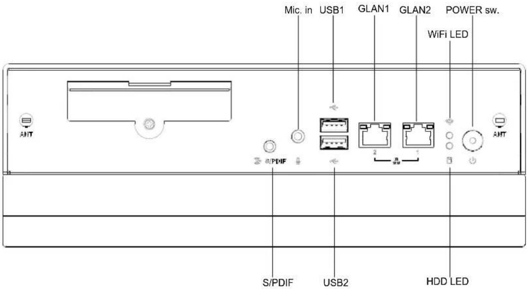
Figure 2.1 DS-980 (Expansion) front view

Figure 2.2 DS-980 (Expansion) rear view
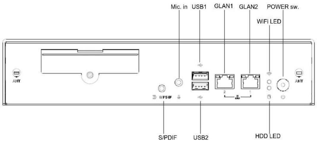
Figure 2.3 DS-980GL (Light) front view

Figure 2.4 DS-980GL (Light) rear view
2.2 DS-980/DS-980GL Front External I/O Connectors
2.2.1 Power ON/OFF Button
DS-980/DS-980GL has a power ON/OFF button on front side. Push this button to turn the system ON and OFF. It can also support 4 second delay soft power off.

Figure 2.5 Power button
2.2.2 Ethernet Connector (GLAN)
DS-980/DS-980GL provides 2 x RJ-45 (LAN1: Intel I219 with Phy only, LAN2: Intel I211 with Phy & Mac), and wake on LAN supported. They are fully compliant with IEEE 802.3u 10/100/1000 Base-T CSMA/CD standards. The Ethernet port provides a standard RJ-45 jack connector with LED indicators on the front side to show its Link (On)/ Active (Flash) and speed status which is with its green color by 100Mbps (On)/ 10Mbps (Off) and its orange color by 1000Mbps (On).

Figure 2.6 GLAN connector
Table 2.1: GLAN Connector Pin Assignments
| Pin Signal Name | |||
| 1 | M | D | I |
| 2 | M | D | I |
| 3 | M | D | I |
| 4 | M | D | I |
| 5 | GND | ||
| 6 | GND | ||
| 7 | M | D | I |
| 8 | M | D | I |
| 9 | M | D | I |
| 10 MDI3- | |||
| 11 VCC | |||
| 12 ACT | |||
| 13 Link100# | |||
| 14 Link1000# | |||
2.2.3 USB2.0 Connector
The front side provides 2x USB 2.0 complaint interfaces, which give complete Plug & Play and hot swapping capability for up to 127 external devices. They are compliant with USB UHCI, Rev. 2.0. The USB ports support Plug and Play, which enables to connect or disconnect a device without turning off the computer.

Figure 2.7 USB2.0 connector
Table 2.2: USB Port Pin Assignments
| Pin Signal Name | |
| 1 | VCC |
| 2 USB Data- | |
| 3 USB Data+ | |
| 4 | GND |
2.2.4 Mic-in Connector
Microphone can be connected to the audio jack. (Pink color) and can be Mic-in input functions.

Figure 2.8 Audio connector
2.2.5 SPDIF/ Line-Out Connector
The S/PDIF port is default setting and allows you to transfer digital sound to an amplifier or television. Also, it supports jack-sense by Line-out functions and you can use either SPDIF or Line-out function by plug option.

Figure 2.9 SPDIF/ Line-out connector
2.3 DS-980/DS-980GL Rear External I/O Connectors
2.3.1 COM Connector
DS-980/DS-980GL provides two D-sub 9-pin connectors serial communication interface port, and supports 1x RS-232 (default setting) or 2x RS-485 & RS-422 with extension cable.

Figure 2.10 COM connector
Table 2.3: COM Port Pin Assignments
| Pin Signal Name | |
| 1 | DCD |
| 2 | RxD |
| 3 | TxD |
| 4 | DTR |
| 5 | GND |
| 6 | DSR |
| 7 | RTS |
| 8 | CTS |
| 9 | RI |
2.3.2 USB3.0 Connector
There are 4x USB3.0 complaint interfaces which are compliant with USB UHCI, Rev. 3.0 and support Plug and Play. It is convenient to enable you to connect or disconnect a device without turning off the computer.

Figure 2.11 USB3.0 connector
Table 2.4: USB 3.0 Connector Pin Assignments
| Pin Signal Name | |||
| 1 VBUS | |||
| 2 USB Data- | |||
| 3 USB Data+ | |||
| 4 | GND | ||
| 5 | S | t | d |
| 6 | S | t | d |
| 7 GND_DRAIN | |||
| 8 | S | t | d |
| 9 | S | t | d |
2.3.3 HDMI Connector
There are three HDMI connectors, which are HDMI1, HDMI2, HDMI3 respectively, to display the high resolution image/video. The detailed descriptions are as below.
HDMI 2.0 (printed HDMI1) is the latest connector to provide all-digital audio/video interface to transmit the uncompressed audio/video signals and with HDCP content protection. Also, its maximum resolution enables to carry 4K resolution at 60Hz but the actual resolutions supported depend on the monitor being used.
■ HDMI 1.4 (printed HDMI2) also supports CEC (Consumer Electronic Control) feature designed to allow the user to perform remote control functions but the actual functions supported depend on the monitor, and maximum resolution is 4K at 30Hz.
■ HDMI 1.4 (printed HDMI3) supports its maximum resolution 4K at 30Hz.

Figure 2.12 HDMI connector
Table 2.5: HDMI Connector Pin Assignments
| Pin Signal Name | |||
| 1 | T | M | D |
| 2 | GND | ||
| 3 | T | M | D |
| 4 | T | M | D |
| 5 | GND | ||
| 6 | T | M | D |
| 7 | T | M | D |
| 8 | GND | ||
| 9 | T | M | D |
| 10 TMDS Clock+ | |||
| 11 GND | |||
| 12 TMDS Clock- | |||
| 13 NC | |||
| 14 NC | |||
| 15 SCL | |||
| 16 SDA | |||
| 17 GND | |||
| 18 +5 V Power | |||
| 19 Detect | |||
2.3.4 Power Input Connector
DS-980/DS-980GL comes with a DC-Jack header that takes 12V DC-in external power input at main layer, and optional second 12V DC-in at bottom layer.

DC-IN 12V
Figure 2.13 DC input connector at main layer

12V

Figure 2.14 DC input connector at bottom layer
Chapter 3
Hardware Installation
This chapter introduces DS-980/DS-980GL series Hardware installation.
3.1 Before you begin
■ Turn off the device, disconnect the Ethernet cable, and disconnect the power cord.
■ Transfer the device to a clean, flat, stable work surface over a noncarpeted floor.
Caution!

Advantech strongly recommends that you look for our global service centers to change any parts which you want in order to ensure our great product quality and make sure the functions well.
3.2 Socket Type CPU & Thermal Module Installation
- Respectively remove 4 screws with number 1 and 2 six-angle screws with number 2 at the back of the plate.
- Push DS-980/DS-980GL top case (number 3) back, then remove it.
- Socket type CPU (number 5) installation
3.1. Unhook the socket lever by pushing down and away from the socket, and gently press socket lever and the load plate will lift from the socket.
3.2. Open the load plate and make sure not to damage any of the pins inside of the socket, and align the notches on the CPU to the notches in the socket.
3.3. Lower the processor straight down into the socket and the load plate back so it is resting on the CPU.
3.4 Press the socket lever to ensure the load plate tip engages under the socket.
3.5 Carefully lock the lever back into place.
- Thermal module (number 4) installation
4.1. Remove the paper template on the thermal grease first, and gently place the thermal module on CPU socket without any pressure.
4.2. Tighten 4 screws on the thermal module with diagonal directions to balance each pressure on CPU.
4.3. Connect the thermal cable to the connector printed CPUFAN1 on motherboard.
- After completed 3 & 4 procedures, please push DS-980/DS-980GL top case (number 3) towards the front side and exactly cover the system. Then, tighten all the screws (number 1 & 2) back on the chassis.

Figure 3.1 Socket type CPU & Thermal module installation
3.3 DDR4 SO-DIMM Memory Installation
-
Respectively remove 4 screws with number 1 and 2 six-angle screws with number 2 at the back of the plate.
-
Push DS-980/DS-980GL top case (number 3) back, then remove it.
-
Install DDR4 SO-DIMM memory into the appropriate SO-DIMM slots.
-
After completed it, please push DS-980/DS-980GL top case (number 3) towards the front side and exactly cover the system. Then, tighten all the screws (number 1 & 2) back on the chassis.

Figure 3.2 DDR4 SO-DIMM memory installation
3.4 2.5-inch SATA Storage Installation (Main Layer)
- Remove 1 screw (number 3) at the front plate, and pull the storage tray out from the device.
- Please note the 2.5-inch SATA storage direction upside down and assemble on the storage tray with 4 screws (number 1).
- Push the completed storage module back to the device and exactly ensure the 2.5-inch SATA storage connection with SATA connector inside.
- Then, tighten 1 screw (number 3) back.
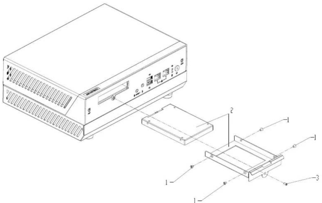
Figure 3.3 2.5-inch SATA storage installation (main layer)
3.5 2.5-inch SATA SSD Installation (Bottom Layer)
- Upside down the device first on a flat and clear floor.
-
If necessary, please remove all the screws (number 1, 2, & 3) at the bottom side including stand rubbers or mounting brackets.
-
Carefully lift up the bottom case (number 4).
-
2.5-inch SATA module installation 4.1. Gently insert 4 yellow rubbers (number 5) into the storage tray. 4.2. Install 2.5-inch SATA on this storage tray (number 6) by 4 step screws (number 7) from the side.
-
Make sure to connect SATA cable and SATA power cable with 2.5-inch SATA SSD and flatly install this SATA module by 4 screws (number 8). Properly place both cables behind the nuts and keep a clear look.
-
Carefully put the bottom case down and make sure to cover the whole device, then tighten all the screws (number 1, 2, & 3) back.

Figure 3.4 2.5-inch SATA SSD installation (bottom layer)
3.6 Graphic Card & Fan Duct Installation (option)
- Upside down the device first on a flat and clear floor.
- If necessary, please remove all the screws (number 1, 2, & 3) at the bottom side including stand rubbers or mounting brackets.
- Carefully lift up the bottom case (number 4).
- First check whether the graphic card bracket size is long or not. If not, please change to the long size with 2 screws (number 7).
- Insert the graphic card into the slot at the bottom case.
- Exactly check all the outputs location of the graphic card, and tighten 1 screw (number 5) at the side.
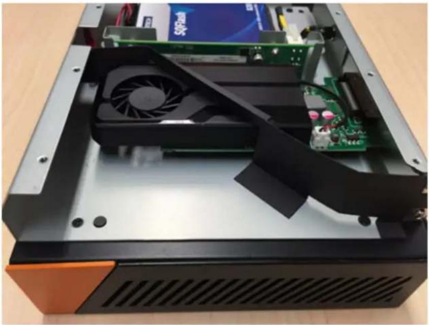
- Carefully attach a fan duct on T mark on the bottom case following the right directions with below photos.
- Carefully put the bottom case down and make sure to cover the whole device, then tighten all the screws (number 1, 2, & 3) back.
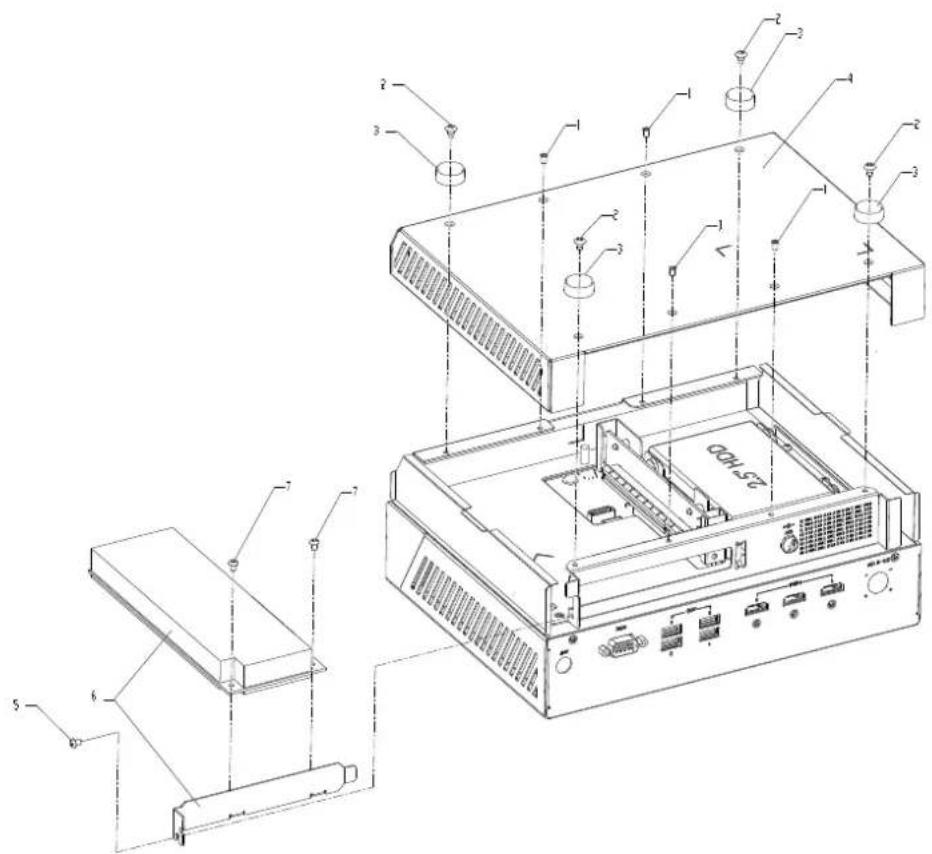
Figure 3.5 Graphic card installation

natural_image
Internal view of a computer drive bay showing CPU socket, fan, and SIM card (no readable text or symbols)Figure 3.6 Fan duct location (1)
natural_image
Interior view of a computer tower case showing CPU socket, fan, and motherboard (no visible text or symbols)Figure 3.7 Fan duct location (2)
3.7 Mini-PCIe Card/ SIM Card/ M.2 WIFI Module Installation (Options)
- Respectively remove 4 screws with number 1 and 2 six-angle screws with number 2 at the back of the plate.
- Push DS-980/DS-980GL top case back, then remove it.
- Install mini-PCIe card on its mini-PCIe slot (number 3)/ SIM card on its SIM slot (number 6)/ M.2 WIFI module with 1 screw (number 4) on its M.2 2230 slot (number 5).
- After completed it, please push DS-980/DS-980GL top case towards the front side and exactly cover the system. Then, tighten all the screws (number 1 & 2) back on the chassis.
Note!Mini PCIe slot supports mSATA or mini PCIE card.


Figure 3.8 Mini-PCIe card/ SIM card/ M.2 WIFI module installation
3.8 Antenna Installation (Options)
-
Respectively remove 4 screws with number 1 and 2 six-angle screws with number 2 at the back of the plate.
-
Push DS-980/DS-980GL top case back, then remove it.
-
Clean the antenna holes which you want to use and fix the WIFI cable (number 3) on them by rubbers, nuts, and six-angle screws.
-
After completed it, please push DS-980/DS-980GL top case towards the front side and exactly cover the system. Then, tighten all the screws (number 1 & 2) back on the chassis.
-
Install the external antennas (number 4) and make sure to properly tighten them.
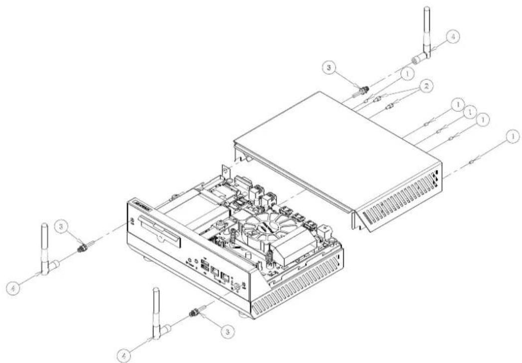
Figure 3.9 Antenna installation
3.9 Mounting Brackets Installation
- Upside down the device first on a flat and clear floor.
- Both of DS-980/DS-980GL configurations, using the middle of screw holes to install the mounting brackets (number 2) by 4 screws (number 1) (M3x6L).
- Exactly ensure the mounting brackets are fixed and stable.

Figure 3.10 Mounting brackets installation
Note! Please select the suitable screws and consider your loading of the safety value when you install DS-980/DS-980GL behind to the monitor, (DS-980/DS-980GL with expansion configuration weight is 3.8kg; light configuration is 3.1kg)
3.10 Stand Rubbers Installation
- Upside down the device first on a flat and clear floor.
- Both of DS-980/DS-980GL configurations, using the outer of screw holes to install the stand rubbers (number 2) by 4 screws (number 1).
- Upside down the device and exactly make sure the stand rubbers are fixed and keep the device balance.

Figure 3.11 Stand rubbers installation
3.11 VESA Brackets Installation
- Upside down the device first on a flat and clear floor.
- Both of DS-980/DS-980GL configurations, using the middle of screw holes to install the mounting brackets (number 2) by 4 screws (number 1) (M3x6L).
- Gently place VESA bracket (number 3) on the mounting brackets with the right holes which mark DS-9XX printings and tighten 4 screws (number 4) (M4x 10L) with the opposite directions to the monitor.
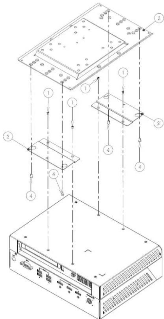
Figure 3.12 VESA brackets installation
Note!

Please select the suitable screws and consider your loading of the safety value when you install DS-980/DS-980GL behind to the monitor, (DS-980/DS-980GL with expansion configuration weight is 3.8kg; light configuration is 3.1kg)
3.12 How to Select Suitable Graphic Cards
DS-980/DS-980GL is designed for the expansion slot by PCI Express x16 slot at the bottom layer in order to fulfill video wall solution with triple+ displays which depends on what quantities of its outputs a graphic card is. Due to the limited space of DS-980/DS-980GL bottom layer, there are below criteria to select your suitable graphic card.
- Foam factor: Low Profile
- Bracket side: Long
- Maximum GPU, TDP (Walt): 75W
- Maximum board dimension (Unit: mm): 167.65(L) x 68.9(W)

Figure 3.13 Maximum board dimension (Unit: mm)
- Maximum a graphic card dimension:
■ Top side with thermal mechanism: 15.62mm
PCBA: 1.57mm
■ Bottom side: 2.67mm

Figure 3.14 Maximum a graphic card dimension (Unit: mm)
- Air Inlet Location:
To efficiently enhance the airflow road inside, so please notice air inlet location should be "at the slash location" following a below picture so that it is able to attach fan duct properly.
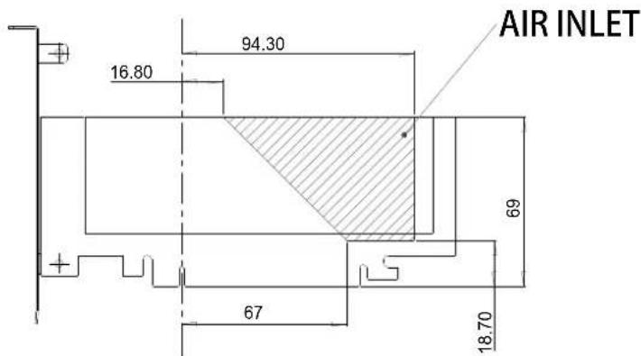
Figure 3.15 Air inlet location
Note! To ensure DS-980/DS-980GL operation smoothly, it is better to use second 12V DC-in AC adapter which we recommended when a graphic card is installed.

Chapter 4
BIOS Settings
This chapter introduces how to set BIOS configuration data.
4.1 BIOS Introduction
AMI BIOS has been integrated into many motherboards for over two decades. With the AMI BIOS Setup program, you can modify BIOS settings and control various system features. This chapter describes the basic navigation of the DS-980/DS-980GL series BIOS setup screens.
AMI BIOS's ROM has a built-in setup program that allows users to modify the basic system configuration. This information is stored in flash part CMOS so it retains the setup information when the power is turned off.
There are some different settings with 6th Intel processor compared with the previous platform, so please notice these following procedures of DS-980/DS-980GL series BIOS.
4.2 Entering Setup
4.2.1 Main Setup
When you first enter the BIOS Setup Utility, you will enter the Main setup screen. You can always return to the Main setup screen by selecting the Main tab.
The Main BIOS setup screen has two main frames. The left frame displays all the options that can be configured. Options in blue can be configured, and grayed-out options cannot be configured instead. The right frame displays the key legend.
The key legend in the top is an area reserved for a text message. When an option is selected in the left frame, it is highlighted in white. Often a text message will accompany it.
You can use main setup to check BIOS related information and DS-980/DS-980GL hardware settings, such as project version, build date and time, power type, total memory, memory frequency, ME FW version, and system date/time.
In this screen, only system date and time can be adjusted if you wanted. Highlight System Time or System Date using the
![Aptio Setup Utility - Copyright (C) 2016 American Megatrends, Inc. Main Advanced Chipset Security Boot Save & Exit BIOS Information BIOS Vendor American Megatrends Core Version 5.0.1.1 0.30 x64 Compliancy UEFI 2.4; PI 1.3 Project Version DS D980000S060X017 Build Date and Time 03/31/2016 09:02:19 Access Level Administrator Power Type ATX Total Memory 4096 MB Memory Frequency 2133 MHz ME FW Version 11.0.0.1205 ME Firmware SKU Corporate SKU System Language [English] System Date [Tue 04/25/2045] System Time [11:23:43] Choose the system default language +: Select Screen ↑↓: Select Item Enter: Select +/-: Change Opt. F1: General Help F2: Previous Values F3: Optimized Defaults F4: Save & Exit ESC: Exit Version 2.17.1255. Copyright (C) 2016 American Megatrends, Inc.](/content/2026/05/818830/images/e627c1f402062c8aba381a36d372f9c111bf0e5331439e3ff8df89cde4ca9e59.jpg)
Figure 4.1 Main setup
4.2.2 Advanced Features Setup
Select the Advanced tab from the DS-980/DS-980GL setup screen to enter the Advanced BIOS setup screen. You can select any of the items in the left frame of the screen, such as CPU configuration, to go to the sub menu for that item. You can display an Advanced BIOS Setup option by highlighting it using the

Figure 4.2 Advanced features setting
4.2.2.1 ACPI Settings
ACPI is a subsystem which controls hardware states (thermal control, motherboard configuration, power states like sleep and suspend, and functions that may have previously been in the BIOS configuration.
If want to change ACPI sleep state, you can select the highest ACPI sleep state the system will enter the SUSPEND button is pressed. Configuration options: [Suspend Disable][S1 (CPU Stop Clock)][S3 (suspend to RAM)].
![Aptio Setup Utility - Copyright (C) 2016 American Megatrends, Inc. Advanced ACPI Settings Enable ACPI Auto Configuration [Disabled] Enable Hibernation [Enabled] ACPI Sleep State [S3 (Suspend to RAM)] Lock Legacy Resources [Disabled] Enables or Disables BIOS ACPI Auto Configuration. +: Select Screen 11: Select Item Enter: Select +/-: Change Opt. F1: General Help F2: Previous Values F3: Optimized Defaults F4: Save & Exit ESC: Exit Version 2.17.1255. Copyright (C) 2016 American Megatrends, Inc.](/content/2026/05/818830/images/ea94baf43a0603e3ec6a16242dce1575221d4cf63eda4fe4c521a0de0f3b1a49.jpg)
Figure 4.3 ACPI Setup Screen
4.2.2.2 AMT Configuration
Intel AMT includes hardware-based remote management, security, power management, and remote configuration features that enable independent remote access to AMT-enabled PCs. Intel AMT is security and management technology that is built into PCs with Intel vPro technology. PCs with Intel vPro include many other "platform" (general PC) technologies and features.
Configuration AMT Parameters:
Intel AMT [Enabled]: Enabled/ Disabled AMT; Configuration options: [Disabled][Enabled].
BIOS Hotkey Pressed [Disabled]: Enabled/ Disabled BIOS hotkey pressed; Configuration options: [Disabled][Enabled].
■ MEBx Selection Screen [Disabled]: Enabled/ Disabled MEBx selection screen; Configuration options: [Disabled][Enabled].
- Hide Un-Configure ME Confirmation Prompt [Disabled]: Hide Un-configure ME without password configuration prompt; Configuration options: [Disabled][Enabled].
■ MEBx Debug Message Output [Disabled]: Enabled/ Disabled MEBx debug message output; Configuration options: [Disabled][Enabled].
■ Un-Configure ME [Disabled]: Un-Configure ME without password; Configuration options: [Disabled][Enabled].
■ AMT Wait timer [0]: Set timer to wait before sending ASF_GET_BOOT_OPTION.
■ ASF [Enabled]: Enabled/ Disabled alert specification format; Configuration options: [Disabled][Enabled].
■ Active Remote Assistance Process [Disabled]: Trigger CIRA boot; Configuration options: [Disabled][Enabled].
USB Provisioning of AMT [Enabled]: Enabled/ Disabled USB provisioning of AMT; Configuration options: [Disabled][Enabled].
PET [Enabled]: User can Enabled/ Disabled PET Events progress to receive PET events or not; Configuration options: [Disabled][Enabled].
■ AMT CIRA Timeout [0].
- WatchDog Timer [Disabled]: Enabled/ Disabled WatchDog Timer; Configuration options: [Disabled][Enabled]. When [Enabled], OS and BIOS WatchDog Timers can be set.
![Aptio Setup Utility - Copyright (C) 2016 American Megatrends, Inc. Advanced Intel AMT [Enabled] BIOS Hotkey Pressed [Disabled] MEBx Selection Screen [Disabled] Hide Un-Configure ME Confirmation [Disabled] Prompt MEBx Debug Message Output [Disabled] Un-Configure ME [Disabled] Amt Wait Timer 0 ASF [Enabled] Activate Remote Assistance Process [Disabled] USB Provisioning of AMT [Enabled] PET Progress [Enabled] AMT CIRA Timeout 0 WatchDog [Disabled] OS Timer 0 BIOS Timer 0 Enable/Disable Intel (R) Active Management Technology BIOS Extension. Note : iAMT H/H is always enabled. This option just controls the BIOS extension execution. If enabled, this requires additional firmware in the SPI device +: Select Screen ↑↓: Select Item Enter: Select +/-: Change Opt. F1: General Help F2: Previous Values F3: Optimized Defaults F4: Save & Exit ESC: Exit Version 2.17.1255. Copyright (C) 2016 American Megatrends, Inc.](/content/2026/05/818830/images/c95d92dd3f797c040ea02fce4528cf93ae93309855fab29531b4514d440521bc.jpg)
Figure 4.4 AMT Configuration
4.2.2.3 PCH-FW Configuration
Configuration Management Engine Technology Parameter.
■ Display ME Firmware Information
![Aptio Setup Utility - Copyright (C) 2016 American Megatrends, Inc. Advanced ME FW Version 11.0.0.1205 ME Firmware Mode Normal Mode ME Firmware Type Full Sku Firmware ME Firmware SKU Corporate SKU ME State [Enabled] ▶ Firmware Update Configuration Configure Management Engine Technology Parameters +: Select Screen ↑↓: Select Item Enter: Select +/-: Change Opt. F1: General Help F2: Previous Values F3: Optimized Defaults F4: Save & Exit ESC: Exit Version 2.17.1255, Copyright (C) 2016 American Megatrends, Inc.](/content/2026/05/818830/images/bbae72e0c283143d41e5410d9ead459c1648fe861e6f14f33d075aff1c114b8c.jpg)
Figure 4.5 PCH-FW Configuration
■ Firmware Update Configuration
Enabled/ Disabled ME FW image Re-Flash function: Configuration options: [Disable][Enhanced].
![Aptio Setup Utility - Copyright (C) 2016 American Megatrends, Inc. Advanced Me FW Image Re-Flash [Disabled] Enable/Disable Me FW Image Re-Flash function. +: Select Screen ↑↓: Select Item Enter: Select +/-: Change Opt. F1: General Help F2: Previous Values F3: Optimized Defaults F4: Save & Exit ESC: Exit Version 2.17.1255. Copyright (C) 2016 American Megatrends, Inc.](/content/2026/05/818830/images/becbd91c7e5d3fcf1935b8ae365fc4c205061842030d511fd23976db2edded79.jpg)
Figure 4.6 ME FW image
4.2.2.4 ITE8528E Super IO Configuration
System Super IO Chip Parameters.
■ Super IO Configuration: Super IO Chip [ITE8528E].

Figure 4.7 ITE8528E Super IO Configuration
Serial Port 1 Configuration: Set Parameters of Serial Port 1.
- Serial Port [Enabled]: Enabled/ Disabled Serial Port; Configuration options: [Disabled][Enabled].
- Device Setting [IO=3F8h; IRQ=4].
- Change Setting [Auto]: Select an optimal setting for Super IO device.
![Aptio Setup Utility - Copyright (C) 2016 American Megatrends, Inc. Advanced Serial Port 1 Configuration Serial Port [Enabled] Device Settings IO=3F8h; IRQ=4; Change Settings [Auto] COM1 Mode [RS-232 Mode] Enable or Disable Serial Port (COM) +: Select Screen ↑↓: Select Item Enter: Select +/-: Change Opt. F1: General Help F2: Previous Values F3: Optimized Defaults F4: Save & Exit ESC: Exit Version 2.17.1255. Copyright (C) 2016 American Megatrends, Inc.](/content/2026/05/818830/images/e1cef761506b3b7327a033ee586300bd547f7dc3cd950eef8d6798ddd3f91396.jpg)
4.2.2.5 ITE8528E HW Monitor
Monitor hardware status (PC health status): Display system health status.
![Aptio Setup Utility - Copyright (C) 2016 American Megatrends, Inc. Advanced PC Health Status EC Firmware Version I288AX0008 CPU temperature : +46°C System temperature : +32°C CPUFAN Speed : 1001 RPM SYSFAN Speed : N/A VBAT : +3.072 V 5VS8 : +5.042 V +12V : +11.240 V +5V : +5.014 V +3.3V : +3.296 V Watch Dog Timer [Disabled] Enabled or Disabled Watch Dog Timer function (Start before boot to OS and must stop by self) +: Select Screen ↑↓: Select Item Enter: Select +/-: Change Opt. F1: General Help F2: Previous Values F3: Optimized Defaults F4: Save & Exit ESC: Exit Version 2.17.1255. Copyright (C) 2016 American Megatrends, Inc.](/content/2026/05/818830/images/9a936b42ad0122902297525a84dfc0dc3542f78b47e144bb23983bfc708f20bd.jpg)
Figure 4.8 ITE8528E HW monitor
WatchDog Timer [Disabled]: Enabled/ Disabled WatchDog Timer; When [Enabled], you can change WatchDog Timer Mode is based on [Second] and Time out Value [30] you want.
![Aptio Setup Utility - Copyright (C) 2016 American Megatrends, Inc. Advanced PC Health Status EC Firmware Version I288AX0008 CPU temperature : +46°C System temperature : +32°C CPUFAN Speed : 1002 RPM SYSFAN Speed : N/A VBAT : +3.078 V 5VS8 : +5.032 V +12V : +11.240 V +5V : +5.008 V +3.3V : +3.306 V Watch Dog Timer [Enabled] Watch Dog Timer Mode [Second] Watch Dog Timer Time out Value 30 Enabled or Disabled Watch Dog Timer function (Start before boot to OS and must stop by self) +: Select Screen ↑↓: Select Item Enter: Select +/-: Change Opt. F1: General Help F2: Previous Values F3: Optimized Defaults F4: Save & Exit ESC: Exit Version 2.17.1255. Copyright (C) 2016 American Megatrends, Inc.](/content/2026/05/818830/images/2fa8fa6f871436986dccb022564ab6d8ae7d001ed0e1ea1a03b136e6e9062f3b.jpg)
Figure 4.9 WatchDog Timer setting
4.2.2.6 S5 RTC wake setting
Enable system to wake from S5 using RTC alarm.
| Aptio Setup Utility - Copyright (C) 2016 American Megatrends, Inc. Advanced | |
| Wake system from S5 [Disabled] | Enable or disable System wake on alarm event. Select FixedTime, system will wake on the hr::min::sec specified. Select DynamicTime, System will wake on the current time + Increase minute(s) |
| +: Select Screen ↑↓: Select Item Enter: Select +/-: Change Opt. F1: General Help F2: Previous Values F3: Optimized Defaults F4: Save & Exit ESC: Exit | |
| Version 2.17.1255. Copyright (C) 2016 American Megatrends, Inc. | |
Figure 4.10 S5 RTC wake setting
Wake system from S5 [Disabled]: Enabled/ Disabled Wake system from S5; Configuration options [Disabled][Enabled] and set up Wake up by day/ hour/ minute/ second [0] you want.
![Aptio Setup Utility - Copyright (C) 2016 American Megatrends, Inc. Advanced Wake system from S5 [Enabled] Wake up Day 0 Wake up hour 0 Wake up minute 0 Wake up second 0 Enable or disable System wake on alarm event. Select FixedTime, system will wake on the hr::min::sec specified. Select DynamicTime , System will wake on the current time + Increase minute(s) +: Select Screen ↑↓: Select Item Enter: Select +/-: Change Opt. F1: General Help F2: Previous Values F3: Optimized Defaults F4: Save & Exit ESC: Exit Version 2.17.1255. Copyright (C) 2016 American Megatrends, Inc.](/content/2026/05/818830/images/5a2d18defb49cec1d6518a86cabc0a53d17dfbefd634a77818a9b026bd020ce8.jpg)
Figure 4.11 S5 RTC wake setting
4.2.2.7 Serial port console redirection
Display COM console information.
COM1 – Console Redirection [Disabled]: Enabled/ Disabled COM1 – Console Redirection; Configuration options: [Disabled][Enabled].
Serial Port for Out-of-Band Management [Disabled]: Microsoft Windows Emergency Management Services (EMS) allows for remote management of a Windows Server OS though a serial port.
![Optio Setup Utility - Copyright (C) 2016 American Megatrends, Inc. Advanced COM1 Console Redirection [Disabled] ► Console Redirection Settings Legacy Console Redirection ► Legacy Console Redirection Settings Serial Port for Out-of-Band Management/ Windows Emergency Management Services (EMS) Console Redirection [Disabled] ► Console Redirection Settings Console Redirection Enable or Disable. +: Select Screen +: Select Item Enter: Select +/-: Change Opt. F1: General Help F2: Previous Values F3: Optimized Defaults F4: Save & Exit ESC: Exit Version 2.17.1255, Copyright (C) 2016 American Megatrends, Inc.](/content/2026/05/818830/images/91b503ecc254e4c8ac558a4f675793686fd2d058781423f8dd67f4077f2401b3.jpg)
Figure 4.12 Serial port console redirection
■ Emulation: [ANSI] Extended ASCII Char set.
■ VT100: ASCII char set.
■ VT100+: Extends VT100 to support color, functional keys, etc.
■ VT-UTF8: Uses UTF8 encoding to map Unicode chars onto 1 or more bytes.
![Aptio Setup Utility - Copyright (C) 2016 American Megatrends, Inc. Advanced COM1 Console Redirection Settings Terminal Type [ANSI] Bits per second [115200] Data Bits [8] Parity [None] Stop Bits [1] Flow Control [None] VT-UTF8 Combo Key Support [Enabled] Recorder Mode [Disabled] Resolution 100x31 [Disabled] Legacy OS Redirection Resolution [80x24] Putty KeyPad [VT100] Redirection After BIOS POST [Always Enable] Emulation: ANSI: Extended ASCII char set. VT100: ASCII char set. VT100+: Extends VT100 to support color, function keys, etc. VT-UTF8: Uses UTF8 encoding to map Unicode chars onto 1 or more bytes. +: Select Screen 1↓: Select Item Enter: Select +/-: Change Opt. F1: General Help F2: Previous Values F3: Optimized Defaults F4: Save & Exit ESC: Exit Version 2.17.1255. Copyright (C) 2016 American Megatrends, Inc.](/content/2026/05/818830/images/80cfb15de8f69cc7b5482de3e74078cf2667b421f3bbef44272d6abfb7fbf80c.jpg)
Figure 4.13 COM1 - Console redirection setting
Select a COM port to display redirection of Legacy OS and Legacy OPROM Messages.
![Aptio Setup Utility - Copyright (C) 2016 American Megatrends, Inc. Advanced Legacy Serial Redirection Port [COM1] Select a COM port to display redirection of Legacy OS and Legacy OPROM Messages +: Select Screen ↑↓: Select Item Enter: Select +/-: Change Opt. F1: General Help F2: Previous Values F3: Optimized Defaults F4: Save & Exit ESC: Exit Version 2.17.1255. Copyright (C) 2016 American Megatrends, Inc.](/content/2026/05/818830/images/47b431c79281f9e06d6cb9085c1e1902811b09ac1fa72695bae4dac2a610a56b.jpg)
Figure 4.14 Legacy console redirection setting
Microsoft Windows Emergency Management Services (EMS) allows for remote management of a Windows Server OS through a serial port.
![Aptio Setup Utility - Copyright (C) 2016 American Megatrends, Inc. Advanced Out-of-Bard Mgmt Port [COM1] Terminal Type [VT-UTF8] Bits per second [115200] Flow Control [None] Data Bits 8 Parity None Stop Bits 1 Microsoft Windows Emergency Management Services (EMS) allows for remote management of a Windows Server OS through a serial port. ++: Select Screen ↑↓: Select Item Enter: Select +/-: Change Opt. F1: General Help F2: Previous Values F3: Optimized Defaults F4: Save & Exit ESC: Exit Version 2.17.1255. Copyright (C) 2016 American Megatrends, Inc.](/content/2026/05/818830/images/202b7815ef19938d67436e47e730a9ffde58a2498879e53a731969ec54cb180f.jpg)
Figure 4.15 Serial Port-console redirection setting
4.2.2.8 CPU Configuration
Displays CPU Configuration Parameters:
■ Hyper Threading Technology [Not Suppoerted]
Intel VT-x Technology [Supported]
Intel SMX Technology [Supported]
64-bit [Supported]
■ EIST Technology [Supported]
■ CPU C3 state [Supported]
■ CPU C6 state [Supported]
■ CPU C7 state [Supported]
■ CPU C8 state [Supported]
■ CPU C9 state [Not Supported]
■ CPU C10 state [Not Supported]

Figure 4.16 CPU Configuration (1)
■ Active Processor Cores [All]: Select the numbers of cores in each processor package; Configuration options [All][1][2][3][4][5][6][7] which are subject to each processor type.
Intel Virtualization Technology [Enabled]: When enabled, a VMM can utilize the additional hardware capabilities provided by Vanderpool Technology; Configuration options: [Disabled][Enabled].
Hardware Prefetcher [Enabled]: To turn on/off the Mid Level Cache (L2) steamer Prefetcher; Configuration options: [Disabled][Enabled].
■ Adjacent Cache Line Prefetch [Enabled]: To turn on/off prefetching of adjacent cache lines; Configuration options: [Disabled][Enables].
■ Boot Performance Mode [Max Non-Turbo Performance]
Intel® Speed Shift Technology [Enabled]
Intel® SpeedStep™ Turbo Mode [Enabled]
■ CPU C States [Enabled]
■ Package C State Limit [Auto]
■ SW Guard Extensions (SGX) [Software Controlled]
■ Select Owner EPOCH input type [No Change in Owner EPOCHs]
PRMRR Size [Auto]
![Aptio Setup Utility - Copyright (C) 2016 American Megatrends, Inc. Advanced CPU C8 state CPU C9 state CPU C10 state L1 Data Cache L1 Code Cache L2 Cache L3 Cache L4 Cache Active Processor Cores Intel Virtualization Technology Hardware Prefetcher Adjacent Cache Line Prefetch Boot performance mode Intel(R) Speed Shift Technology Intel(R) SpeedStep(1m) Turbo Mode CPU C states Package C State limit SW Guard Extensions (SGX) Select Owner EPOCH input type PRMRR Size Supported Not Supported Not Supported 32 kB x 4 32 kB x 4 256 kB x 4 6 MB Not Present [All] [Enabled] [Enabled] [Max Non-Turbo Performance] [Enabled] [Enabled] [Enabled] [AUTO] [Software Controlled] [No Change in Owner EPOCHS] [AUTO] There are three Owner EPOCH nodes (Each EPOCH is 64bit): no change in owner epoch, charge to new random owner epoch and manually entered by user. After the user enters epoch values manually, the values will not be visible, for security reasons. +: Select Screen ↑↓: Select Item Enter: Select +/-: Change Opt. F1: General Help F2: Previous Values F3: Optimized Defaults F4: Save & Exit ESC: Exit Version 2.17.1255. Copyright (C) 2016 American Megatrends, Inc.](/content/2026/05/818830/images/d595242ab2af1833c788d9f21b4ebc653a6bda6ccf46eb74271ea0671a2e2df0.jpg)
Figure 4.17 CPU Configuration (2)
4.2.2.9 Intel TXT information
Display Intel TXT Parameters.

Figure 4.18 Intel TXT information
4.2.2.10 SATA configuration
■ SATA Mode [AHCI]: Support IDE, AHCI, or RAID mode; Configuration options: [Disabled][IDE][AHCI][RAID].
Serial ATA Port 1: Enabled/ Disabled SATA Device; Configuration options: [Disabled][Enabled]
| SATA Controller(s) | [Enabled] | Enable or disable SATA Device. |
| SATA Mode Selection | [AHCI] | |
| Serial ATA Port 1 | Empty | |
| Software Preserve | Unknown | |
| Port 1 | [Enabled] | |
| SATA Device Type | [Hard Disk Drive] | |
| Serial ATA Port 2 | Empty | |
| Software Preserve | Unknown | |
| Port 2 | [Enabled] | |
| SATA Device Type | [Hard Disk Drive] | |
| mSATA | Empty | |
| Software Preserve | Unknown | |
| mSATA | [Enabled] | |
| SATA Device Type | [Hard Disk Drive] | |
| +: Select Screen 1↓: Select Item Enter: Select +/-: Change Opt. F1: General Help F2: Previous Values F3: Optimized Defaults F4: Save & Exit ESC: Exit |
Figure 4.19 SATA configuration
4.2.2.11 Network Stack Configuration
Enabled/ Disabled UEFI Network Stack; Configuration options: [Disabled][Enabled].
![Aptio Setup Utility - Copyright (C) 2016 American Megatrends, Inc. Advanced Network Stack [Disabled] Enable/Disable UEFI Network Stack +: Select Screen ↓: Select Item Enter: Select +/-: Change Opt. F1: General Help F2: Previous Values F3: Optimized Defaults F4: Save & Exit ESC: Exit Version 2.17.1255. Copyright (C) 2016 American Megatrends, Inc.](/content/2026/05/818830/images/0058d3ca6d3215710171dafaa62cbeb8b1a64ce1b8dee8926a4c5baabf48f15c.jpg)
Figure 4.20 Network Stack Configuration – Disabled
![Aptio Setup Utility - Copyright (C) 2016 American Megatrends, Inc. Advanced Network Stack [Enabled] Ipv4 PXE Support [Enabled] Ipv6 PXE Support [Enabled] PXE boot wait time 0 Media detect count 1 Enable/Disable UEFI Network Stack +: Select Screen 1↓: Select Item Enter: Select +/-: Change Opt. F1: General Help F2: Previous Values F3: Optimized Defaults F4: Save & Exit ESC: Exit Version 2.17.1255. Copyright (C) 2016 American Megatrends, Inc.](/content/2026/05/818830/images/5cafbff2e969aaa17a1d45fd85b1561ed41c6465fbef6e3ea4103d4ce6dc1aa8.jpg)
Figure 4.21 Network Stack – enable
4.2.2.12 CSM configuration
Disabled/ Enabled CSM support; Configuration options: [Disabled][Enabled].
| Aptio Setup Utility - Copyright (C) 2016 American Megatrends, Inc. Advanced | |
| Compatibility Support Module Configuration | Enable/Disable CSM Support. |
| CSM Support [Enabled] | |
| CSM16 Module Version 07.79 | |
| GateA20 Active [Upon Request] INT19 Trap Response [Immediate] | |
| Boot option filter [UEFI only] | |
| Option ROM execution | |
| Network [UEFI] | +: Select Screen ↑↓: Select Item Enter: Select +/-: Change Opt. F1: General Help F2: Previous Values F3: Optimized Defaults F4: Save & Exit ESC: Exit |
| Storage [UEFI] | |
| Video [UEFI] | |
| Other PCI devices [UEFI] | |
| Version 2.17.1255. Copyright (C) 2016 American Megatrends, Inc. | |
Figure 4.22 CSM Configuration
4.2.2.13 USB configuration
Disabled/ AUTO/ Disabled USB Configuration; Configuration options: [Enabled][Disabled][AUTO].
■ [Enabled] Legacy USB support.
■ [AUTO] disables legacy support if no USB devices are connected.
■ [Disabled] option will only for EFI application.
![Optio Setup Utility - Copyright (C) 2016 American Megatrends, Inc. Advanced USB Configuration USB Module Version 13 USB Controllers: 1 XHCI USB Devices: 1 Drive, 1 Keyboard, 1 Mouse, 1 Hub Legacy USB Support [Enabled] XHCI Hand-off [Enabled] USB Mass Storage Driver Support [Enabled] Port 60/64 Emulation [Disabled] USB hardware delays and time-outs: USB transfer time-out [20 sec] Device reset time-out [20 sec] Device power-up delay [Auto] Mass Storage Devices: KingstonDataTraveler 3.0PMAP [Auto] Enables Legacy USB support. AUTO option disables legacy support if no USB devices are connected. DISABLE option will keep USB devices available only for EFI applications. +: Select Screen ↑↓: Select Item Enter: Select +/-: Change Opt. F1: General Help F2: Previous Values F3: Optimized Defaults F4: Save & Exit ESC: Exit Version 2.17.1255. Copyright (C) 2016 American Megatrends, Inc.](/content/2026/05/818830/images/eca33a2b4bf11bb0c8ba6671e8876deb2f6b19b1b6e27972aa202a2258ab2cb0.jpg)
Figure 4.23 USB configuration
4.2.3 Chipset
Display System Agent (SA) Parameters.

Figure 4.24 Chipset
4.2.4 System Agent
■ VT-d [Enabled]: Set VT-d Enabled/ Disabled; Configuration options: [Disabled][Enabled].
■ Graphics Configuration, PEG Port Configuration, and GT – Power Management Control setting options.
■ Display Memory Configuration information.
![Aptio Setup Utility - Copyright (C) 2016 American Megatrends, Inc. Chipset VT-d [Enabled] ► Graphics Configuration ► PEG Port Configuration ► GT - Power Management Control Memory Configuration Total Memory 4096 MB DIMM A1 Not Present DIMM B1 4096 MB Max TOLUD [Dynamic] VT-d capability +: Select Screen ↑↓: Select Item Enter: Select +/-: Change Opt. F1: General Help F2: Previous Values F3: Optimized Defaults F4: Save & Exit ESC: Exit Version 2.17.1255, Copyright (C) 2016 American Megatrends, Inc.](/content/2026/05/818830/images/b777437807b6786e8f99ea50d630064ce7a4480fa780bb972d5ae00c5c7f4a5f.jpg)
Figure 4.25 System Agent
Graphic Configuration: if enabled, it will not scan for external GFX Card on PEG and PCH PCIE Ports.
![Aptio Setup Utility - Copyright (C) 2016 American Megatrends, Inc. Chipset Graphics Configuration Skip Scanning of External Gfx Card [Disabled] Primary Display [Auto] Internal Graphics [Enabled] GTT Size [8MB] Aperture Size [256MB] DVMT Pre-Allocated [32M] DVMT Total Gfx Mem [256M] Gfx Lou Power Mode [Enabled] If Enable, it will not scan for External Gfx Card on PEG and PCH PCIE Ports +: Select Screen ↑↓: Select Item Enter: Select +/-: Change Opt. F1: General Help F2: Previous Values F3: Optimized Defaults F4: Save & Exit ESC: Exit Version 2.17.1255. Copyright (C) 2016 American Megatrends, Inc.](/content/2026/05/818830/images/3aa007edacb73fc43f98a51e5fd7d2920688871341d8c00061a9726ff9a1f962.jpg)
Figure 4.26 Graphic Configuration
PEG Port Configuration: Enabled/ Disabled the Root Port.
![Aptio Setup Utility - Copyright (C) 2016 American Megatrends, Inc. Chipset PEG Port Configuration PEG 0:1:0 Not Present Enable Root Port [Auto] Max Link Speed [Auto] PEGO Slot Power Limit Value 75 PEGO Slot Power Limit Scale [1.0x] PEGO Physical Slot Number 1 Detect Non-Compliance Device [Disabled] Program PCIe ASPM after OpROM [Disabled] Program Static Phase1 Eq [Enabled] ► Gen3 Root Port Preset value for each Lane ► Gen3 Endpoint Preset value for each Lane ► Gen3 Endpoint Hint value for each Lane ► Gen3 RxCTLE Control Gen3 Adaptive Software Equalization Always Attempt SW EQ [Disabled] Number cf Presets to test [Auto] Allow PERST# GPIO Usage [Enabled] SW EQ Enable VOC [Auto] Jitter Dwell Time 3000 Jitter Error Target 2 VOC Dwell Time 10000 VOC Error Target 2 Enable or Disable the Root Port +: Select Screen ↑↓: Select Item Enter: Select +/-: Change Opt. F1: General Help F2: Previous Values F3: Optimized Defaults F4: Save & Exit ESC: Exit Version 2.17.1255. Copyright (C) 2016 American Megatrends, Inc.](/content/2026/05/818830/images/102a8151c4f2b5e2188e507514fc37fde0abf0a0664d9af7647d73a735c791bc.jpg)
Figure 4.27 PEG Port Configuration
4.2.4.1 PCH-IO configuration
Display PCH Parameters. Check to enabled render standby support.
![Aptio Setup Utility - Copyright (C) 2016 American Megatrends, Inc. Chipset GT - Power Management Control GT Info GT2 RC6(Render Standby) [Enabled] Check to enable render standby support. +: Select Screen ↑↓: Select Item Enter: Select +/-: Change Opt. F1: General Help F2: Previous Values F3: Optimized Defaults F4: Save & Exit ESC: Exit Version 2.17.1255. Copyright (C) 2016 American Megatrends, Inc.](/content/2026/05/818830/images/1cafb451839eabe8bdd6bf2215340f31ed51d40174f288199bad2ce6f668551b.jpg)
Figure 4.28 PCH-IO configuration
PCI Express Clock Gating [Enabled]: Enable/ Disabled PCI Express clock gating for each root port; Configuration options: [Disabled][Eanbled].
■ DMI Link ASPM Control [Enabled]: Enabled/ Disabled the control of active state power management on SA side of the DMI link; Configuration options: [Disabled].
■ PCIE Port 5 is assigned to LAN: Mini PCI Express & M.2.
![Aptio Setup Utility - Copyright (C) 2016 American Megatrends, Inc. Chipset PCI Express Configuration PCI Express Clock Gating [Enabled] DMI Link ASPM Control [Enabled] PCI Express Gen3 Eq Lanes PCIE Port 5 is assigned to LAN Mini PCI Express M.2 Enable or disable PCI Express Clock Gating for each root port. +: Select Screen +: Select Item Enter: Select +/-: Change Opt. F1: General Help F2: Previous Values F3: Optimized Defaults F4: Save & Exit ESC: Exit Version 2.17.1255. Copyright (C) 2016 American Megatrends, Inc.](/content/2026/05/818830/images/82531d86bb301567aef42c49003f09419f8f2d3a6b993f6c088fbfed56afed65.jpg)
Figure 4.29 PCI express Configuration
Override SW EQ settings [Disabled]: Disabled/ Enabled Override SW EQ settings; Configuration options: [Disabled][Enabled].
![Aptio Setup Utility - Copyright (C) 2016 American Megatrends, Inc. Chipset Override SW EQ settings [Disabled] +: Select Screen ↑↓: Select Item Enter: Select +/-: Change Opt. F1: General Help F2: Previous Values F3: Optimized Defaults F4: Save & Exit ESC: Exit Version 2.17.1255. Copyright (C) 2016 American Megatrends, Inc.](/content/2026/05/818830/images/77979e11fdaa64531aa9f46d819a97b4285e8c01f28d98fe73987863e858f0a9.jpg)
Figure 4.30 PCI express Gen3 EQ Lanes
Mini PCI Express settings, and control the PCI Express Root Port.
Mini PCI Express [Enabled]: Enabled/ Disabled to control Mini PCI Express; Configuration options: [Disabled][Enabled][Auto]
■ ASPM Support [Auto]
■ L1 Substates [L1.1 & L1.2]
Gen3 Eq Phase3 Method [Software Search]
■ UPTP [5]
DPTP [7]
ACS [Enabled]
- URR [Disabled]
- FER [Disabled]
- NFER [Disabled]
- CER [Disabled]
- CTO [Disabled]
- SEFE [Disabled]
- SENFE [Disabled]
- SECE [Disabled]
- PME SCI [Enabled]
- Advanced Error Reporting [Enabled]
PCIe Speed [Auto]
■ Detect Non-Compliance Device [Disabled]
Extra Bus Reserved [0]
Reserved Memory [10]
■ Prefetchable Memory [10]
Reserved I/O [4]
PCIE Cp [2]
PCIE Cm [6]
■ PCIE LTR [Enabled]
■ PCIE LTR Lock [Disabled]
■ PCH PCIe CLKREQ# Configuration: PCIE16 CLKREQ Mapping Override [Default], Snoop Latency Ocerrice [Auto], Non Snoop Latency Ocerride [Auto]
![Aptio Setup Utility - Copyright (C) 2016 American Megatrends, Inc. Chipset Mini PCI Express Topology ASPM Support L1 Substates Gen3 Eq Phase3 Method UPTP DPTP ACS URR FER NFER CER CTO SEFE SENFE SECE PME SCI Advanced Error Reporting PCIe Speed Transmitter Half Swing Detect Non-Compliance Device Extra Bus Reserved Reserved Memory Prefetchable Memory Reserved I/O [Enabled] [Unknown] [Auto] [L1.1 & L1.2] [Software Search] 5 7 [Enabled] [Disabled] [Disabled] [Disabled] [Disabled] [Disabled] [Disabled] [Disabled] [Disabled] [Disabled] [Disabled] [Disabled] [Disabled] Control the PCI Express Root Port. +: Select Screen ↓: Select Item Enter: Select +/-: Change Opt. F1: General Help F2: Previous Values F3: Optimized Defaults F4: Save & Exit ESC: Exit Version 2.17.1255. Copyright (C) 2016 American Megatrends, Inc.](/content/2026/05/818830/images/b4409fc31b6670695542f04a116dc2220d57d29c54c3fb33007be2673b49589f.jpg)
Figure 4.31 Mini PCI Express/ M.2 (1)
![Aptio Setup Utility - Copyright (C) 2016 American Megatrends, Inc. Chipset FER [Disabled] NFER [Disabled] CER [Disabled] CTO [Disabled] SEFE [Disabled] SENFE [Disabled] SECE [Disabled] PME SCI [Enabled] Advanced Error Reporting [Enabled] PCIe Speed [Auto] Transmitter Half Swing [Disabled] Detect Non-Compliance Device [Disabled] Extra Bus Reserved 0 Reserved Memory 10 Prefetchable Memory 10 Reserved I/O 4 PCIE Cp 2 PCIE Cm 6 PCIE LTR [Enabled] PCIE LTR Lock [Disabled] PCH PCIe CLKREQ# Configuration PCIE16 CLKREQ Mapping Override [Default] Snoop Latency Occride [Auto] Non Snoop Latency Occride [Auto] Non Snoop Latency Occride for PCH PCIE. +: Select Screen ↑↓: Select Item Enter: Select +/-: Change Opt. F1: General Help F2: Previous Values F3: Optimized Defaults F4: Save & Exit ESC: Exit Version 2.17.1255. Copyright (C) 2016 American Megatrends, Inc.](/content/2026/05/818830/images/dddfbb089ff97b88f1d62bce11cb33c4314b86275fd7c7c6bdbae80276a70d35.jpg)
Figure 4.32 Mini PCI Express/ M.2 (2)
Precondition work on USB host controller and root ports for faster enumeration.
■ USB Precondition [Disabled]
■ XHCI Disable Compliance Mode [FALSE]
USB Port Disable Override [Disabled]
![Aptio Setup Utility - Copyright (C) 2016 American Megatrends, Inc. Chipset USB Configuration USB Precondition [Disabled] XHCI Disable Compliance Mode [FALSE] USB Port Disable Override [Disabled] Precondition work on USB host controller and root ports for faster enumeration. +: Select Screen ↑↓: Select Item Enter: Select +/-: Change Opt. F1: General Help F2: Previous Values F3: Optimized Defaults F4: Save & Exit ESC: Exit Version 2.17.1255. Copyright (C) 2016 American Megatrends, Inc.](/content/2026/05/818830/images/926a0efe5c062d03321938d0f604a6d91849d4e98324df0d744b9683a5a1bf68.jpg)
Figure 4.33 USB configuration
Control Detection of HD-Audio device [Auto]
■ [Disabled] HDA will be unconditionally disabled.
■ [Enabled] HDA will be unconditionally enabled.
■ [Auto] HDA will be enabled if present, disabled otherwise.
![Aptio Setup Utility - Copyright (C) 2016 American Megatrends, Inc. Chipset HD Audio Configuration HD Audio [Auto] Control Detection of the HD-Audio device. Disabled = HDA will be unconditionally disabled Enabled = HDA will be unconditionally enabled Auto = HDA will be enabled if present, disabled otherwise. +: Select Screen +: Select Item Enter: Select +/-: Change Opt. F1: General Help F2: Previous Values F3: Optimized Defaults F4: Save & Exit ESC: Exit Version 2.17.1255. Copyright (C) 2016 American Megatrends, Inc.](/content/2026/05/818830/images/08a3df3f51f72fcbb6ec3f772087ec810ae725a8610049a565c85178fede0157.jpg)
Figure 4.34 HD Audio Configuration
4.2.5 Security
■ Administrator Password: Set up Administrator password.
■ User Password: set up User password.

Figure 4.35 Security
4.2.6 Boot
Setup Prompt Timeout [1]: Number of seconds to wait for setup activation key. 65535 (0xFFFF) means indefinite waiting.
■ Bootup NumLock State [On]: Select the keyboard NumLock State; Configuration options: [On][Off].
■ Quick Boot [Disabled]: Configuration options: [Disabled][Enabled].
■ Boot Option Priorities: Select the system boot order.
Fast Boot [Disabled]: Enabled/ Disabled boot with initialization of minimal set of devices required to launch active boot option. Has no effect for BBS boot options; Configuration options: [Disabled][Enabled].
■ New Boot Option Policy [Default].
![Aptio Setup Utility - Copyright (C) 2016 American Megatrends, Inc. Main Advanced Chipset Security Boot Save & Exit Boot Configuration Setup Prompt Timeout Bootup NumLock State Quiet Boot Boot Option Priorities Boot Option #1 Fast Boot New Boot Option Policy 1 [On] [Disabled] [UEFI: KingstonDataTraveler 3.0PMAP, Partition 1] [Disabled] [Default] Number of seconds to wait for setup activation key. 65535(0xFFFF) means indefinite waiting. +: Select Screen ↑↓: Select Item Enter: Select +/-: Change Opt. F1: General Help F2: Previous Values F3: Optimized Defaults F4: Save & Exit ESC: Exit Version 2.17.1255. Copyright (C) 2016 American Megatrends, Inc.](/content/2026/05/818830/images/cc5e9ae0f6c3c315a6cc24635164801e1406fb3e872fd6c382485a44bc2d143f.jpg)
Figure 4.36 Boot
4.2.7 Save & Exit
■ Save Changes and Exit: Exit system setup after saving the changes.
- Discard changes and Exit: Exit system setup without saving the changes.
■ Save changes and Reset: Reset the system after saving the changes.
- Discard Changes and Reset: Reset the system without saving the changes.
■ Save Changes: Save changes done with any of the setup option.
- Discard Changes: Discard changes done with any of the setup option.
- Restore Defaults: Restore/ Load default values for all the setup option.
■ Save as User Defaults: Save the changes done as User Defaults.
- Restore User Defaults: Restore the user defaults to all the setup options.

Figure 4.37 Save & Exit
ADVANTECH
Enabling an Intelligent Planet
www.advantech.com
Please verify specifications before quoting. This guide is intended for reference purposes only.
All product specifications are subject to change without notice.
No part of this publication may be reproduced in any form or by any means, electronic, photocopying, recording or otherwise, without prior written permission of the publisher.
All brand and product names are trademarks or registered trademarks of their respective companies.
© Advantech Co., Ltd. 2016

- DS-980/DS-980GL
- Copyright
- Acknowledgements
- Product Warranty (2 years)
- Technical Support and Assistance
- Warnings, Cautions and Notes
- Battery Information
- Packing List
- Optional Recommended Parts
- Safety Instructions
- Contents
- Chapter 1 General Introduction ......1
- Chapter 2 External I/O introduction......7
- Chapter 3 Hardware Installation ....15
- Chapter 4 BIOS Settings....31
- Chapter 1
- General Introduction
- Introduction
- Product Features
- General
- Display
- Power Consumption
- RISER Card:
- Hardware Specifications
- ■ CPU (LGA 1151, TDP up to 35W):
- System Chipset: Intel® Q170
- BIOS: AMI uEFI 128 Mbit
- System Memory:
- ■ Graphic chipset: Intel® HD Graphics 530
- ■ Storage: (supports RAID 0/1 function)
- ■ Watchdog Timer: 1-255 seconds, supported by Advantech SUSI4.0 API
- I/O Interface:
- Internal Expansion:
- Operating System:
- Mechanical Specifications
- Dimensions
- Weight
- Power Requirements
- System Power
- RTC Battery
- Environment Specification
- Chapter 2
- DS-980/DS-980GL Front and Rear views
- DS-980/DS-980GL Front External I/O Connectors
- Power ON/OFF Button
- Ethernet Connector (GLAN)
- USB2.0 Connector
- Mic-in Connector
- SPDIF/ Line-Out Connector
- DS-980/DS-980GL Rear External I/O Connectors
- COM Connector
- USB3.0 Connector
- HDMI Connector
- Power Input Connector
- Chapter 3
- Hardware Installation
- Before you begin
- Caution!
- Socket Type CPU & Thermal Module Installation
- DDR4 SO-DIMM Memory Installation
- 2.5-inch SATA Storage Installation (Main Layer)
- 2.5-inch SATA SSD Installation (Bottom Layer)
- Graphic Card & Fan Duct Installation (option)
- Mini-PCIe Card/ SIM Card/ M.2 WIFI Module Installation (Options)
- Antenna Installation (Options)
- Mounting Brackets Installation
- Stand Rubbers Installation
- VESA Brackets Installation
- How to Select Suitable Graphic Cards
- Chapter 4
- BIOS Settings
- BIOS Introduction
- Entering Setup
- Main Setup
- Advanced Features Setup
- ACPI Settings
- AMT Configuration
- PCH-FW Configuration
- ■ Firmware Update Configuration
- ITE8528E Super IO Configuration
- ITE8528E HW Monitor
- S5 RTC wake setting
- Serial port console redirection
- CPU Configuration
- Intel TXT information
- SATA configuration
- Network Stack Configuration
- CSM configuration
- USB configuration
- Chipset
- System Agent
- PCH-IO configuration
- Security
- Boot
- Save & Exit
- ADVANTECH
- www.advantech.com
Brand : Advantech
Model : DS-980GL
Category : Media player