
Sapphire Gas Log Fire - Heating Rinnai - Free user manual and instructions
Find the device manual for free Sapphire Gas Log Fire Rinnai in PDF.


| Product Type | Gas Log Fire |
| Brand | Rinnai |
| Model | Sapphire |
| Fuel Type | Natural Gas or Propane (conversion kit available) |
| BTU Rating | 30,000 BTU/hr |
| Dimensions (HxWxD) | 30 x 20 x 15 inches |
| Weight | 30 lbs |
| Venting | Vent-Free (no chimney required) |
| Flame Control | Remote control with variable flame height |
| Thermostat | Built-in thermostat for automatic operation |
| Ignition | Electronic ignition (battery operated) |
| Safety Features | Oxygen Depletion Sensor (ODS), Cool-Touch Glass Front |
| Log Set | Ceramic fiber logs with realistic appearance |
| Pilot Light | Standing pilot (manual or automatic lighting) |
| Annual Maintenance | Clean logs and burner, check for obstructions |
| Spare Parts Available | Log set, burner, pilot assembly, remote control |
| Installation | Professional installation required |
| Warranty | 5-year limited warranty |
| Certifications | ANSI Z21.11.2, CSA (Canada) |
| Energy Efficiency | Up to 99% efficiency (vent-free) |
Frequently Asked Questions - Sapphire Gas Log Fire Rinnai
User questions about Sapphire Gas Log Fire Rinnai
0 question about this device. Answer the ones you know or ask your own.
Ask a new question about this device
Download the instructions for your Heating in PDF format for free! Find your manual Sapphire Gas Log Fire - Rinnai and take your electronic device back in hand. On this page are published all the documents necessary for the use of your device. Sapphire Gas Log Fire by Rinnai.
USER MANUAL Sapphire Gas Log Fire Rinnai
natural_image
Illustration of a two-view architectural installation showing a fire extinguisher mounted on a chimney, with its side view below (no text or symbols present)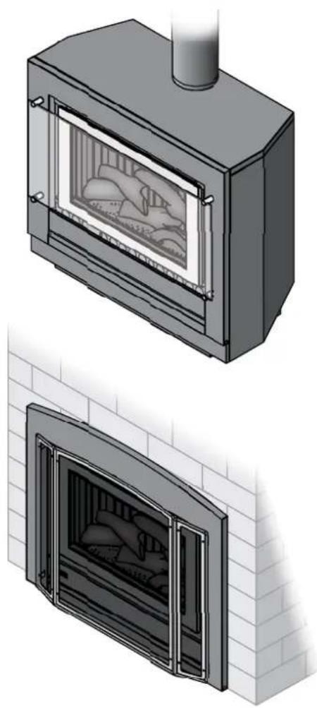
natural_image
Illustration of a two-view architectural installation showing a fire extinguisher and its closed doors, both mounted on a brick wall (no text or symbols present)This appliance shall be installed in accordance with:
• Manufacturer's Installation Instructions
• Current AS/NZS 5601 AS/NZS 3000
- Local Regulations and Municipal Building Codes including local OH&S requirements
This appliance must be installed, maintained and removed by an Authorised Person.
For continued safety of this appliance it must be installed and maintained in accordance with the manufacturers instructions.

N10378

The Australian
Gas Association
All Rinnai gas products are A.G.A. certified.
Congratulations on the purchase of your Rinnai Sapphire gas log flamefire. We trust you will have many years of comfort and enjoyment from your appliance.
BEFORE PROCEEDING WITH THE OPERATION OR INSTALLATION OF YOUR NEW HEATER PLEASE READ THIS MANUAL THOROUGHLY AND GAIN A FULL UNDERSTANDING OF THE REQUIREMENTS, FEATURES AND OPERATION OF YOUR NEW APPLIANCE.
ABOUT YOUR HEATER 10
GENERAL DESCRIPTION.... 10
DESIGN FEATURES....11
CONTROL PANEL OPERATION....12
TO TURN YOUR HEATER ON 12
FLAME HEIGHT & FAN SPEED SETTINGS 12
TO TURN YOUR HEATER OFF 12
INTERRUPTION TO ELECTRICITY OR GAS SUPPLY DURING OPERATION.... 12
RESTART PROCEDURE AFTER INTERRUPTION TO ELECTRICITY SUPPLY 12
RESTART PROCEDURE AFTER INTERRUPTION TO GAS SUPPLY 12
REMOTE / THERMOSTATIC CONTROLLED OPERATION.... 13
REMOTE CONTROLLER - BATTERY INSTALLATION 13
REMOTE CONTROLLER - SYNCHRONISATION. 14
TROUBLE SHOOTING CHECKLIST 23
ABNORMAL FLAME PATTERN....23
TABLE OF CONTENTS - INSTALLATION.... 25
CONTACT INFORMATION 56
BEFORE YOU START
INSTALLATION REQUIREMENTS
This heater must be installed by an authorised person. The installation must conform to local regulations.
The installation must also comply with the instructions supplied by Rinnai.
Service and removal must be carried out by an authorised person.
CERTIFICATION
The Rinnai Sapphire ^® has been certified by the Australian Gas Association.
The AGA Certification Number is shown on the appliance dataplate.
No parts or functions should be modified or permanently removed from the heater.
Please keep these instructions in a safe place for future reference.
CARTON CONTENTS / ITEM CHECKLIST
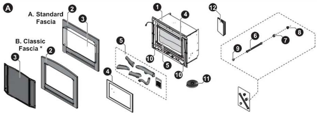
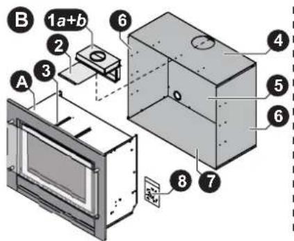
The components for Sapphire heater are supplied in separate cartons, the following tables list which components are in each carton. Ensure that the components listed for the installation method being installed are present before proceeding with the installation.

The Engine and Fascia are packed into two separate cartons and are required for all installation types. Masonry installations may require a flexiliner flue to be installed, refer to “MASONRY FLUE INSTALLATION” on page 33 for details.
text_image
A A. Standard Fascia B. Classic Fascia * 1 2 3 4 5 6 7 8 9 10 11 12 13 14 15 16 17 18 19 20 21 22 23 24 25 26 27 28 29 30 31 32 33 34 35 36 37 38 39 40 41 42 43 44 45 46 47 48 49 50| Component Descriptions* The Classic fascia / Mesh dress guard is suitable for Masonry and Zero Clearance - Inbuilt Installation installations ONLY! It and can NOT be used on a Console or Plinth installation. | Carton Contents | ||
| Engine Fascia | |||
| A Engine and Fascia - Masonry Installations (x2 Cartons) | |||
| 1 | Rinnai Sapphire Engine. | ● | |
| 2 | A. Fascia (Standard Model) / B. Fascia (Classic Model)*. | ● | |
| 3 | A. Glass dress guard (Standard Model) / B. Mesh dress guard (Classic Model)*. | ● | |
| 4 | Inner metal surround. | ● | |
| 5 | Artificial log set / burn media, Satchel burner granules (shipped inside engine). | ● | |
| 6 | Semi rigid stainless steel gas pipe with 5/8" connections (x1). | ● | |
| 7 | 1⁄2" BSP - 5/8" UNF flared brass adaptors (x1). | ● | |
| 8 | 1⁄2" BSP Flared nut (x1). | ● | |
| 9 | 5/8" UNF Plug (x1). | ● | |
| 10 | Fascia attachment screws (2 x 8g black, pre-fitted in tabs of heater engine). | ● | |
| 11 | Adhesive backed foam sealing strip. | ● | |
| 12 | Operation and Installation manual. | ● | |
BEFORE YOU START
text_image
B 1a+b 2 3 A 6 4 5 6 8 7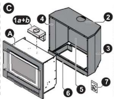
text_image
C 1a+b A 4 2 3 6 5 7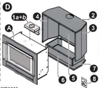
text_image
D 1a+b A 2 3 4 5 6 7 8 HURPOS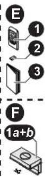
Note: Standard model fascia shown for illustrative purposes
| Component Descriptions | Carton Contents | |||||||
| Engine | Fascia | Zero Clearance Box | Console | Plinth | Remote Thermostat | Spigot Adaptor | ||
| B Zero Clearance - Inbuilt Installation (x3 Cartons) | ||||||||
| A | See Engine and Fascia (Masonry Installations) contents on previous page. | ● | ● | |||||
| 1 | Two piece Spigot Adapter Top Half and Bottom Half. | ● | ||||||
| 2 | Spigot guide panel. | ● | ||||||
| 3 | Spigot guide rails (x2). | ● | ||||||
| 4 | Zero Clearance - Top panel. | ● | ||||||
| 5 | Zero Clearance - Rear panel. | ● | ||||||
| 6 | Zero Clearance - Left & Right side panels. | ● | ||||||
| 7 | Base panel. | ● | ||||||
| 8 | Packet assembly screws (x27), grommets (x2) and rivets (x2). | ● | ||||||
| C Console Installation - Freestanding Installation (x3 Cartons) | ||||||||
| A | See Engine and Fascia (Masonry Installations) contents on previous page. | ● | ● | |||||
| 1 | Two piece Spigot Adapter Top Half and Bottom Half. | ● | ||||||
| 2 | Console Installation - Top panel. | ● | ||||||
| 3 | Console Installation - Left side panel. | ● | ||||||
| 4 | Console Installation - Right side panel. | ● | ||||||
| 5 | Console Installation - Rear panel. | ● | ||||||
| 6 | Console Installation - Pillar. | ● | ||||||
| 7 | Packet assembly screws 35 x 8g and 7 x M5. | ● | ||||||
| D Plinth Installation - Freestanding Installation (x3 Cartons) | ||||||||
| A | See Engine and Fascia (Masonry Installations) contents on previous page. | ● | ● | |||||
| 1 | Two piece Spigot Adapter Top Half and Bottom Half. | ● | ||||||
| 2 | Plinth Installation - Top panel. | ● | ||||||
| 3 | Plinth Installation - Left side panel. | ● | ||||||
| 4 | Plinth Installation - Right side panel. | ● | ||||||
| 5 | Plinth Installation - Rear panel. | ● | ||||||
| 6 | Plinth Installation - Pillar assembly. | ● | ||||||
| 7 | Plinth Installation - Base panel. | ● | ||||||
| 8 | Packet assembly screws 35 x 8g (only 29 needed for installation) and 7 x M5. | ● | ||||||
| E Optional Wireless Remote / Thermostatic Control (x1 Carton) | ||||||||
| 1 | Wireless remote/thermostatic control with wall mount. | ● | ||||||
| 2 | AA batteries (x2). | ● | ||||||
| 3 | Operating Instruction. | ● | ||||||
| F Optional Two Piece Spigot Adapter (x1 Carton) | ||||||||
| 1 | Two piece Spigot Adapter Top Half, Bottom Half and assembly screws (x4) | ● | ||||||
INSTALLATION RECORD
INSTALLERS / GAS FITTERS DETAILS
Installers Name: ____
Company Name: ____
Company Address:
Company Contact Details
Telephone:
Mobile Phone: ____
Certificate of Compliance / Certification Number: ____
Authorised Persons - Licence Number: ____
Installers Signature: ____
Installation Date: ____
APPLIANCE DETAILS
Model Number: ____
Serial Number: ____
Installation Address: ____

THIS APPLIANCE MUST BE INSTALLED, SERVICED AND REPAIRED BY AN AUTHORISED PERSON.

SAFETY

- Failure to comply with these instructions could result in a fire or explosion, which could cause serious injury, death or property damage.
- Improper installation, adjustments, service or maintenance can cause serious injury, death or property damage. Such work must be performed by an authorised person.
- The appliance must be installed in accordance with the local gas and electrical authority regulations.
- Flue terminal must always vent directly to outdoors.
- DO NOT extend the flue vertically or horizontally in ways other than prescribed in the appliance manufacturers' installation instructions.
- For information on gas consumption, see data plate on the appliance.
- This appliance must not be installed where curtains or other combustible materials could come into contact with it. In some cases curtains may need restraining.
- WARNING: This heater MUST NOT be used if either of the glass panels are damaged.
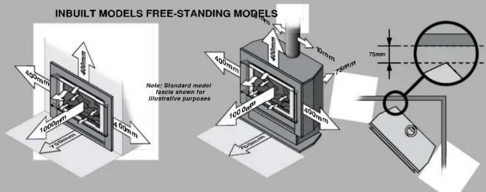
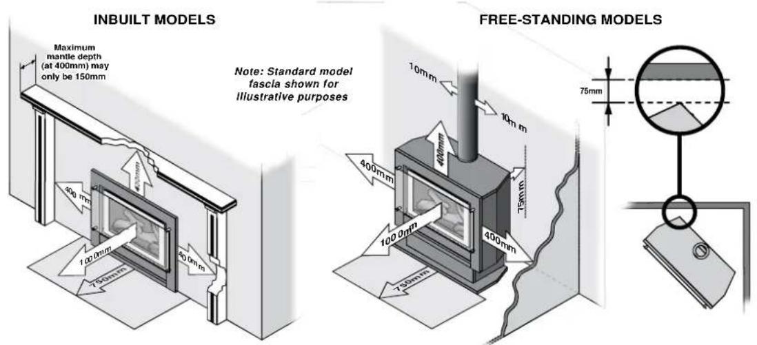
- When considering installation ensure minimum clearances as follows are adhered to:
text_image
INBUILT MODELS FREE-STANDING MODELS Note: Standard model fascia shown for illustrative purposes- Heat radiating from the front of this heater may over time affect the appearance of some materials used for flooring such as carpet, vinyl, cork or timber. This effect may be amplified if the air in the room contains cooking vapours or cigarette smoke. To avoid this possibility, it is recommended that a mat or similar protective sheet be placed in front of the appliance, extending at least 750 mm in front of the dress guard.
- This appliance is not intended for use by persons (including children) with reduced physical, sensory or mental capabilities or lack of experience and knowledge, unless they have been given supervision or instruction concerning use of the appliance by a person responsible for their safety.
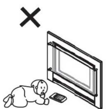
• The appliance is not intended for use by young children or infirm persons without supervision. - Young Children must be supervised when in the vicinity of this heater while it is in operation.
- The Dress Guard MUST be fitted to this appliance to reduce the risk injury from serious burns and no part of it should be permanently removed.
- For protection of young children or the infirm a secondary guard is required.
- If the supply cord is damaged or requires replacing, it must be replaced by the manufacturer or the manufacturer's agent or similarly qualified person in order to avoid a hazard.
- The heater must not be located immediately below a power socket outlet.
- DO NOT connect to an LPG Gas cylinder indoors.
- A dedicated 240 V earthed 10 Amp power point must be used with this appliance.
- DO NOT modify this appliance. Modifying from original specifications may create a dangerous situation and will void your warranty.
- Only the flue components specified by Rinnai must be used.
- Unpack the heater and check for damage. DO NOT INSTALL A DAMAGED HEATER. If the heater is damaged, contact your supplier for advice.
- Before installing the heater, check the label for the correct gas type (refer rating plate, inside the appliance).
- Refer to local gas authority for confirmation of the gas type if you are in doubt.
SAFETY
natural_image
Illustration of a baby crawling under a TV with a cross symbol above (no text or symbols present)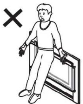
natural_image
Illustration of a person walking with arms and legs, holding a tablet (no text or symbols present)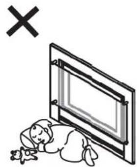
natural_image
Illustration of a sleeping person lying on the floor next to a framed picture with a cross symbol above (no text or symbols present)Note: Standard model fascia shown for illustrative purposes
The appliance is not intended for use by young children or infirm persons without supervision. Young children should always be supervised to ensure that they DO NOT play with the appliance.
DO NOT sit or lean against the heater.
DO NOT allow children or elderly persons to sleep in the warm air discharge from the heater.
natural_image
Diagram showing a hand holding a rectangular object with a cross mark above, no text or symbols present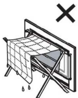
natural_image
Diagram of a folding cloth or sheet with raindrops falling, no text or symbols present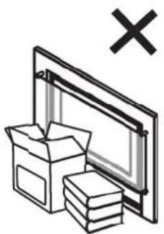
natural_image
Illustration of a box and stack of books next to a computer monitor with an 'X' symbol (no text or labels)Note: Standard model fascia shown for illustrative purposes
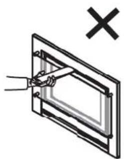
DO NOT post or allow children to post articles into the louvres of the heater.
DO NOT cover or place articles on this heater.
DO NOT place articles in front of the louvres.
natural_image
Illustration of a battery, a switch, and a monitor with an 'X' symbol (no text or labels)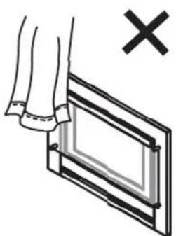
natural_image
Diagram showing a hand holding a rectangular object with a cross mark, no text or symbols present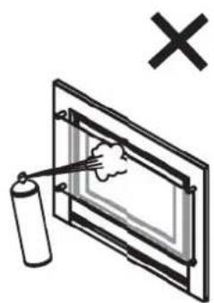
natural_image
Illustration of a spray gun spraying liquid onto a screen, with a battery and an 'X' symbol above (no text or labels)Note: Standard model fascia shown for illustrative purposes
DO NOT operate / install this heater in areas where painting is taking place, or in places such as hairdressing salons, where there may be fluff and dust, and where aerosols are used.
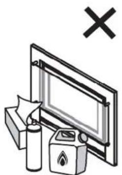
DO NOT place articles on or against this appliance.
DO NOT use or store flammable materials near this appliance. Keep flammable materials away from heater.
Combustible materials MUST NOT be placed where the heater could ignite them.
DO NOT spray aerosols in the vicinity of this appliance while it is in operation. Most aerosols contain flammable substances which can be a heater hazard if used near this heater when it is in use.
SAFETY
text_image
Electrical safety symbols including checkmark, cross, and plug icons with corresponding icons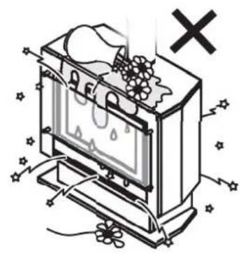
natural_image
Illustration of a vintage TV with a snowflake, flowers, and a 'X' symbol (no text or labels)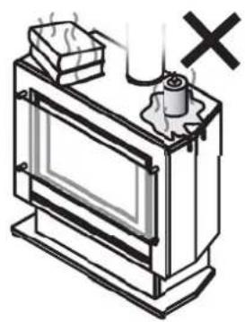
natural_image
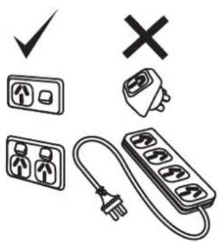
Diagram of a window with a door, a box, and a cross mark indicating a warning or failure (no text or symbols present)A dedicated 240V earthed 10 Amp power point must be used with this appliance.
DO NOT use power boards or double adaptors to operate this appliance. The heater MUST NOT be located below a power socket-outlet.
DO NOT place containers of liquid on top of the heater. Water spillage can cause extensive damage to the appliance and create an electrocution hazard.
DO NOT place articles on or against this appliance.
DO NOT CONNECT TO AN LPG GAS CYLINDER INDOORS.
text_image
Diagram showing a hand using a power plug to interact with a device, marked with an 'X' symbol indicating cancellation or error.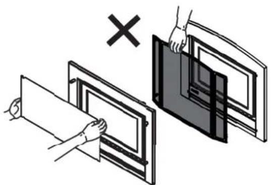
natural_image
Illustration of two hands installing or adjusting a panel with a cross symbol (no text or symbols present)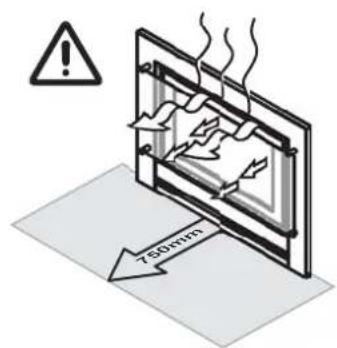
text_image
750mmTurn the heater 'OFF' after use.
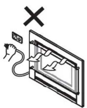
DO NOT unplug the heater while it is in operation or while the fan is still cycling.
DO NOT remove the Dress Guard. The dress guard is fitted to this appliance to reduce the risk of fire or injury from burns and no part of it should be permanently removed. For protection of children or the infirm, a secondary guard is recommended.
Heat emanating from the front of the appliance may over time affect the appearance of some materials used for flooring such as carpet, vinyl, cork or timber. This affect may be amplified if the air in the room contains cooking vapours or cigarette smoke. To avoid this possibility, it is recommended that a mat be placed in front of the appliance, extending at least 750 mm in front of the heater.
When the heater is operated for the first time or after long periods of non use a slight odour may be emitted, this is normal. However if odours persist switch 'OFF' the appliance and contact Rinnai.
SAFETY DEVICES
Over Heat Switches: When the heater gets too hot during operation (for example when air outlet louvres are blocked) these devices turn the gas off automatically and allow the heater to restart when cooled down.
Electrical Fuse: The electrical circuits are protected by a fuse.
Flame Failure Sensing System: This device automatically cuts off the gas supply to the heater in the event of a flame failure.
Power Failure: In the event of a power failure or power cut, the gas valves will automatically close.
ABOUT YOUR HEATER
GENERAL DESCRIPTION
Your Sapphire is a burning log effect, gas space heating appliance with natural draft combustion system, intended for use with Natural Gas, Propane and ULPG. The Burning log effect is achieved using one single main burner with strategically placed, 'life like', imitation logs and granules. Temperature control is achieved by pressing the up or down marked arrows on the manual control switch or via a cordless wall mounted remote control thermostat / timer.
This heater has an electronic ignition with intermittent pilot. The pilot is only on when the heater is in operation.
Burner, logs and granules are contained in a glass fronted, sealed burner box.
Combustion air is drawn from the room. Combustion product is exhausted via the flue discharge vent when installed in a masonry chimney or when installed in a zero clearance box or as a stand alone unit through a 100mm∅ x 150mm∅ twin skinned flue to the outside of the house.
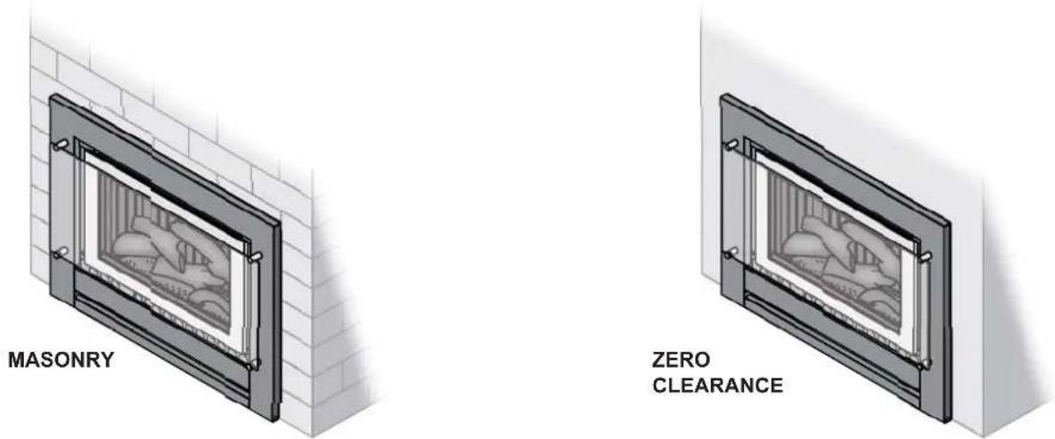
This appliance is modular and primarily consists of an 'Engine' that is utilized in any of the 3 configuration types as listed below.
1. Fireplace / Masonry installation - Engine:
The appliance is directly mounted into an existing masonry fire place or a non-combustible/masonry enclosure that has a chimney. When installed correctly the appliance is a flush to wall mount.
2. Zero Clearance installation:
The Appliance is fitted within a sheet metal Zero Clearance Box Assembly that has been installed into a wall or other suitable structure. Materials need not be non-combustible. When installed correctly the appliance is a flush to wall mount.
3. Freestanding Plinth or Console appliance:
The appliance is housed in a decorative fabricated sheet metal box that is intended to be freestanding and not inbuilt.
text_image
MASONRY ZERO CLEARANCE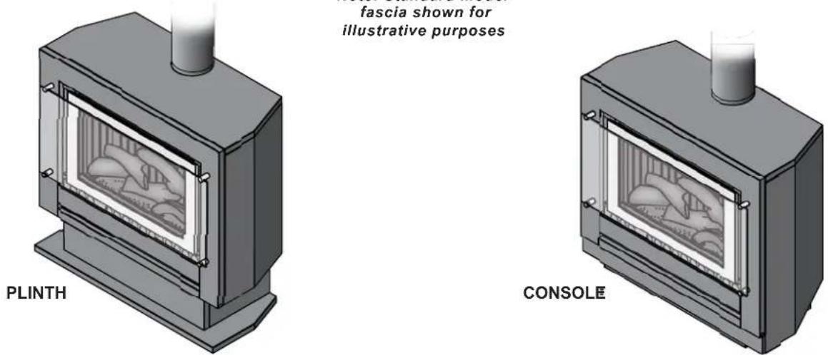
text_image
plINTH fascia shown for illustrative purposes CONSOLEABOUT YOUR HEATER
DESIGN FEATURES
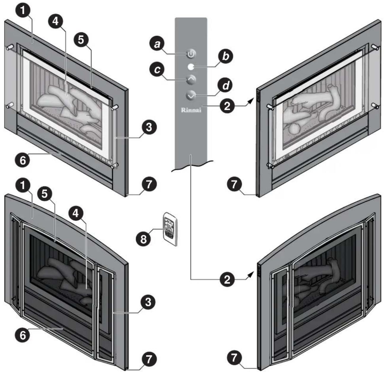
text_image
Rinnai a b c d 2 7 6 1 5 4 3 8 2 7 6 7① Rinnai Sapphire Heater
② Push button control panel
a ON / OFF (Standby) button Pot b r / operation indicator
c Flame Up button Flame Down button
3 Glass dress guard (standard model) / Mesh dress guard (classic model)
④ Flame window - artificial log set and burn media
5 Warm air discharge vent
6 Return air vent
7 Alternative power cable outlet location on front panel can be left or right handed
8 Optional Radio Frequency (RF) combination remote / thermostatic control with wall mount.
When the heater is in the OFF condition (the power supply connected and switched ON but the heater turned OFF) the Power Indicator will be extinguished, this is normal.
The 'Push Button Control Panel' is located at the top left edge of the heater.
Step 1. Press 'ON'/'OFF' button ance. The electronic ignition sparker will be able to be heard.
Step 2. The electronic ignition stops when the pilot flame has been established, the main burner then ignites off the pilot and is automatically preset to Stage 7 - High Flame. The blue LED Power Indicator, b will be constantly illuminated indicating heater is in operation.
Step 3. Flame height may be adjusted after 1 minute of operation. To change the burner and fan settings press c to increase flame height and d to decrease flame height.
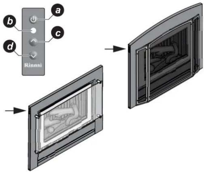
text_image
Rinnai a b c dFLAME HEIGHT & FAN SPEED SETTINGS

The relationship between the flame height and fan speed are preset and can not be independently adjusted.
| F | L | A | M | E | H | E | I | G | H |
| FAN SPEED HIGH | LOW | LOW | LOW | HIGH | HIGH | HIGH | |||
TO TURN YOUR HEATER OFF

When the heater is in the OFF/STANDBY condition (power supply connected and switched ON) the blue LED Power Indicator will be extinguished. This is normal.
To turn the heater 'OFF' press the 'ON'/'OFF' Button a once. The blue LED Power Indicator b, will extinguish to indicate that the appliance has returned to the in OFF condition.
INTERRUPTION TO ELECTRICITY OR GAS SUPPLY DURING OPERATION
Interruption to the power or gas supply will turn your heater off. Restart will be required This is a safety feature designed to ensure that un-attended starts do not occur.
RESTART PROCEDURE AFTER INTERRUPTION TO ELECTRICITY SUPPLY
To restart your heater once power has been restored follow the steps for "TO TURN YOUR HEATER ON" above.
RESTART PROCEDURE AFTER INTERRUPTION TO GAS SUPPLY
The instant gas supply is interrupted the heater will attempt re-ignition for a period of 60 seconds.
If the heater has not re-lit after 60 seconds the gas control will go to 'Gas Lock-out'. The convection fan will remain on for 4 minutes to cool the appliance.
To restart your heater once gas has been restored:
Step 1. Ensure gas supply has been re-established to heater.
Step 2. To re-set the gas control turn 'OFF' the heater by pressing 'ON/OFF' button a once.
Step 3. In rapid succession Press button a, 3 times. (Turn 'ON', then 'OFF', then 'ON' again), within a 5 second period.
REMOTE / THERMOSTATIC CONTROLLED OPERATION
For further enhanced comfort and convenience the Sapphire heater can be both remotely and thermostatically controlled through the use of a wireless wall mountable controller / thermostat.
The wireless controller / thermostat is an optional extra available through your Rinnai stockist.
DISPLAY LAYOUT & FEATURES
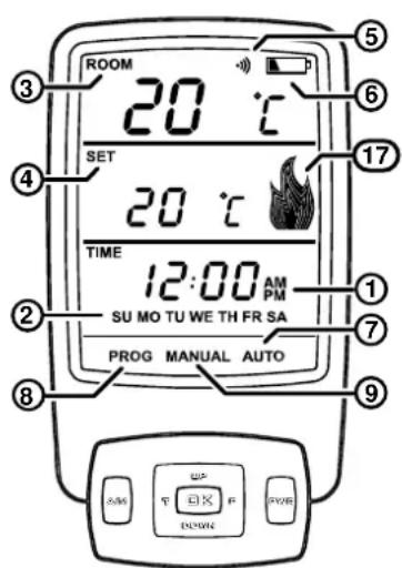
text_image
ROOM 20 ℃ SET 20 ℃ TIME 12:00 AM PM SU MO TU WE TH FR SA PROG MANUAL AUTO 3 4 5 6 17 1 7 8 9 T P DOWN| 1 Time of day with ‘AM’ or ‘PM’ display | Displays time of the day in hours and minutes, ‘AM’ or ‘PM’. The time is displayed when the thermostat is ‘ON’ or ‘OFF’. |
| 2 Day of the week Displays the current day of the week. The day is displayed when the thermostat is ‘ON’ or ‘OFF’. | |
| 3 Current Room temperature display | Displays the current temperature. The temperature range is 7°C - 32°C. |
| 4 Setting Temperature with ‘SET’ display | When the thermostat is ‘ON’, the programmed (set) temperature will be displayed. |
| 5 Transmit indicator Indicates that the thermostat is transmitting to the receiver, the symbol will appear on the LCD for 1 sec. | |
| 6 Battery Low indicator Indicates when the battery power is below an acceptable level. | |
| 7 Automatic mode indicator Indicates if the thermostat is in automatic mode. | |
| 8 Program mode indicator Indicates that the thermostat is in programming mode. | |
| 9 Manual mode indicator Indicates if the thermostat is in manual mode. | |
BUTTON LAYOUT & FEATURES
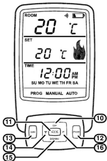
text_image
ROOM 20 °C SET 20 °C TIME 12:00 AM PM SU MO TU WE TH FR SA PROG MANUAL AUTO 11 13 14 15 16 10 T EIX DOWN| 10 Setting ‘UP’ Button | Increase hours, minutes, day or temperature. |
| 11 ‘OK’ Button Accepts the current function and advances to the next function. | |
| 12 ‘PWR’ (Power) Button | Switches the thermostat ‘ON’ and ‘OFF’. To turn ‘ON’ press and release the ‘PWR’ and ‘OK’ Buttons at the same time this will turn the thermostat ‘ON’ to the most recently programmed working mode. |
| 13 ‘A/M’ Button | Toggles between automatic, manual and flame mode. |
| 14 ‘T’ (Time) Button | Initiates time and day of the week programming (must press and hold for 2 or more seconds when the thermostat is ‘OFF’). |
| 15 Setting ‘DOWN’ Button | Decrease hours, minutes, day or temperature. |
| 16 ‘P’ (Program) Button | Initiates the programming mode (must press and hold for 2 or more seconds when the thermostat is ‘OFF’). |
| 17 Flame Indicator | Indicates the flame setting.The Flame symbol graphically indicates which of the 7 graduated settings between Low and High flame when the burner is on.In AUTO or MANUAL temperature mode, if the burner is OFF due to room temperature being reached the symbol will modulate UP and DOWN. This is to indicate that the unit is still ON even though there are no flames visible in the appliance. |
REMOTE CONTROLLER - BATTERY INSTALLATION
Carefully remove the battery compartment cover panel from the rear of your controller hand-set and insert the two AA batteries supplied ensuring that '+' and '-' polarity is correct. After installing the batteries your remote control will display an 'Initial Set-up Screen' with the current room temperature in °C, a default time setting of 12:00 AM and the default day of the week set to 'MO' - Monday.

When batteries are changed all settings other than synchronisation are lost and the controller will revert back to the 'Initial set -up screen'.
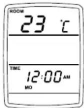
REMOTE CONTROLLER - SYNCHRONISATION.

Before proceeding with synchronisation ensure that the gas and electricity are connected. Synchronisation must be carried out when a new controller has been purchased. Two controllers CAN NOT be used at the same time!
The heater will not respond the controller until synchronisation has been carried out.
Synchronisation of Controller & The Heater
Step 1). Turn the power off at the power point for a minimum of 30 seconds, synchronisation will not be possible unless the minimum 30 seconds has been observed.
Step 2). Ensure the remote control is turned OFF, to turn OFF press and release the 'PWR' button once.
Step 3). Turn the power ON at the power point, the blue power operation indicator b on the push button control panel will flash once. The controller can now be synchronised with the heater.
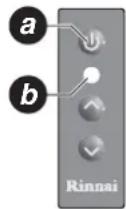

Synchronisation MUST BE performed within 30 seconds of the power being turned ON, if more than 30 seconds has elapsed repeat steps 1 through 3.
Step 4). On the controller in quick succession press the following sequence of buttons: 'P' > 'T' > 'T' > 'UP' The LCD display will show 'L/C' (Learn Code) for 2 seconds then return to the normal 'OFF' state display. The blue power operation indicator b on the push button control panel will flash once to indicate that synchronisation has been accepted.
To restore factory default settings
With the thermostat 'OFF', press the following sequence of buttons 'P' > 'T' > 'T' > 'DOWN'.
Step 1). Press 'ON'/'OFF' button of the Push Button Control Panel a once the Power Indicator LED b, will illuminate blue.
Step 2). Press both the 'OK' and 'PWR' buttons on the controller at the same time. Operational control is now transferred to the controller, the heater operation is then dependant on the controller mode as follows:
In Manual Mode - Unless the set temperature is above that of the room temperature the heater will not ignite and the power Indicator LED b will turn red to indicate that the heater is in Controller Standby mode. Raising the set temperature above that of the room temperature will start heater operation and the Power Indicator LED b will change from red to blue.
Turning 'OFF'
Step 1). To place heater into controller standby press the 'PWR' button once. The heater will go into 'Standby' mode and the power Indicator LED will turn red.
Step 2). To turn the heater 'OFF' press the 'ON'/'OFF' Button twice. The Power Indicator LED , will be extinguished to indicate that the appliance has returned to the OFF condition.
Changing the temperature
The Sapphire has temperature increments of 1° which can be changed using the 'UP' and 'DOWN' buttons.
The temperature control range is 7 - 32°C
Change between Celsius - °C and Fahrenheit - °F
The thermostat temperature display can be set to ^ C or ^ F. The default is ^ C.
With the controller 'OFF', press the following sequence of buttons: 'P' > 'T' > 'T' 'A/M' to toggle between °C or °F.
Change between manual, automatic and flame modes
Press and release the 'A/M' button.
The unit first lights the pilot and then after a short period switches to the 'HIGH' flame setting.
To turn 'OFF' press and release the 'PWR' button once.
REMOTE / THERMOSTATIC CONTROLLED OPERATION
Setting the Current Time and Day of the Week
STEP 1 STEP 2
text_image
TIME 12:00 AM MO UP OK DOWN 14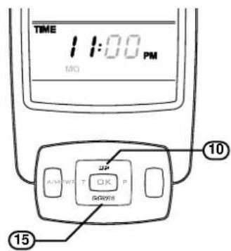
text_image
TIME 1:00 PM MO SP A/W/WR T Q K P GROWER 10 15STEP 3
text_image
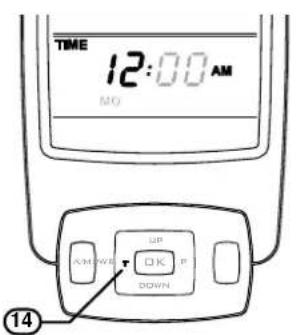
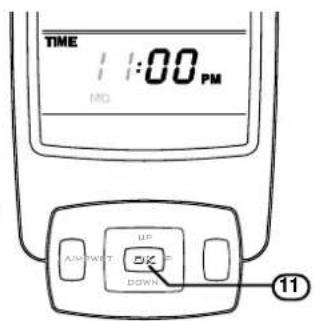
TIME 12:00 PM MD UP DOWN AMOUNT OFF DOWN 11Step 1. With the controller 'OFF', press and hold the 'T' button ⑭ for approximately 2 seconds. 'TIME', 'HOUR' and 'AM or PM' will flash.

If no buttons are pressed within 10 seconds the display will revert back to 'Initial Set-Up Screen' retaining the last entered setting.
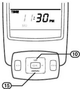
Step 2. To select the hour push the 'UP' button ⑩ or 'DOWN' button ⑮ until the desired hour is chosen, note that AM or PM is chosen by cycling through the 12 hour range.
Step 3. Press the 'OK' button ⑪ to enter the selected hour and AM or PM. 'TIME' + 'MINUTES' + 'AM or PM' will flash.
STEP 4
text_image
TIME 1:30 PM MO 10 OFF OK DOWN 15STEP 5
text_image
TIME 11:30 PM NO UP T DOWN 11STEP 6
text_image
TIME 1:30 PM WE 10 15STEP 7
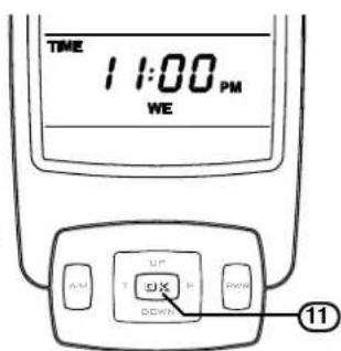
text_image
TIME 11:00 PM WE UP DOWN 11Step 4. To select the minutes push the 'UP' button ⑩ or 'DOWN' button ⑮ until the desired minutes are chosen.
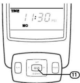
Step 5. Press the 'OK' button ⑪ to enter selected minutes, One of the days SU, MO, TU, WE, TH, FR or SA will flash.
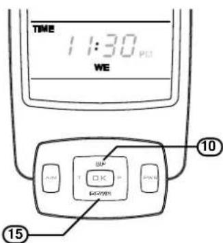
Step 6. To select the hour push the 'UP' button ⑩ or 'DOWN' button ⑮ until the desired day is chosen.
Step 7. Press the 'OK' button ⑪ to enter the selected day and to complete time and day setup.
To adjust time for Daylight Saving time
To adjust time or to adjust for daylight savings follow Steps 1 and 2 then press 'OK' button three times to keep the minutes and the current day.

When changing batteries all settings will be lost and the controller will revert back to the 'Initial setup screen'. Re-setting of time, date and programming will be necessary.
REMOTE / THERMOSTATIC CONTROLLED OPERATION
WIRELESS CONTROLLER / THERMOSTAT
The wireless controller is designed to be wall mounted on a bracket, (bracket supplied with the controller), within 20m of the heater.
The controller houses the thermostat which senses room temperature and communicates back to the Sapphire heater via Radio Frequency.
The ideal position for the controller is:
- Away from possible drafts in the room.
- Away from direct sunlight.
- Suitable distance away from the heater (not exceeding 20 metres).
- Ideally 1.5 ~m from the floor (approximately at chest height).
Controller Specifications
Battery: 2 x AA batteries.
Battery Life: Approximately 12 months.
Dimensions: Height: 140 mm, Width: 80 mm, Depth: 20 mm.
Additional information about Remote Thermostat Control Buttons
| Transmit Indicator | Indicates the thermostat is transmitting to the receiver, the symbol with appear on the LCD for 1 second. |
| Battery Indicator | This symbol will flash when batteries need replacing. The thermostat will remain functional for approximately 5 days before shutting ‘off’. Re-programming of the controller will be required after battery replacement. |
Temperature Display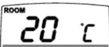 | Displays current temperature. °C is the default but °F is available. The temperature range is 7°C - 32°C (45°F - 90°F). |
Room Indicator or Set Indicator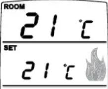 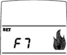 | When the thermostat is ‘ON’ the programmed (set) temperature and the room temperature will be displayed. When the Flame mode is ‘ON’ the Flame setting F7 to F1 will be displayed. |
PWR + OK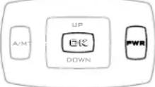 | Switches the thermostat ‘ON’ and ‘OFF’. If thermostat is ‘OFF’, pressing and releasing the ‘PWR’ + ‘OK’ button will turn the thermostat on to the most recently selected working mode. |
T (Time)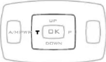 | Initiates the time and day of week programming, press and hold for 2 seconds. |
UP, DOWN & OK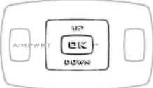 | ‘UP’ increase hours, minutes, day or temperature ‘OK’, accepts the current function and advances to the next function, ‘DOWN’, decrease hours, minutes, day or temperature. |
P (Program)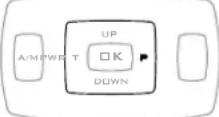 | Initiates the programming mode, press and hold for 2 seconds. |
REMOTE / THERMOSTATIC CONTROLLED OPERATION
Additional information about Remote Thermostat Control Operation
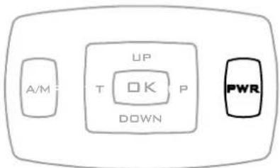
Character Diagnostic Check. To check the display characters on the remote control turn the controller 'off' by pressing the 'PWR' button then press P - T - T - OK in rapid succession.
text_image
A/M UP T OK P DOWN PWR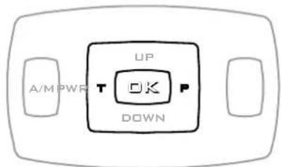
text_image
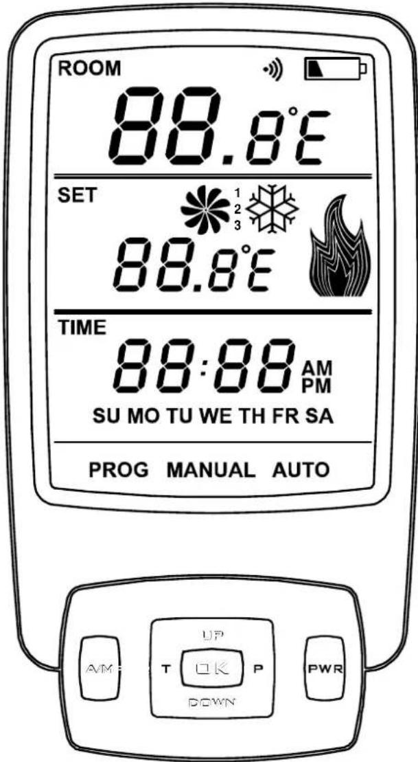
A/M PWR T UP OK P DOWNThe remote will then commence automatically cycling through all the display characters, finally displaying the full screen as shown below.
This process takes approximately 20 seconds and does not affect any programming.
text_image
ROOM 88.8°E SET 88.8°E TIME 88:88 AM PM SU MO TU WE TH FR SA PROG MANUAL AUTO AM UP T OK P DOWN PWR
If any of the characters are not displayed contact your Rinnai stockist for a replacement controller.
The Fan and Snowflake symbols displayed are not utilized in the operation of the Sapphire heater.
REMOTE / THERMOSTATIC CONTROLLED OPERATION
TO TURN YOUR HEATER ON WITH REMOTE / THERMOSTATIC CONTROL

BEFORE PROCEEDING ENSURE THE GAS AND ELECTRICITY ARE TURNED ON.
Before remote / thermostatic control can be used the heater must be taken out of the OFF/STANDBY condition (supply connected and switched ON but the heater turned OFF), do this as follows:
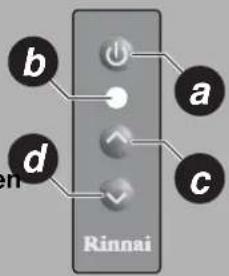
Press 'ON'/'OFF' button a nnce the electronic ignition sparker will be able to be heard.
Step 1. The electronic ignition stops when the pilot flame has been established. The main burner then ignites off the pilot. Once the main burner has ignited the heater can be operated by remote / thermostatic control.
text_image
b a d c RinnaiMODES OF OPERATION
To Turn Remote 'ON' or 'OFF'
text_image
STEP 1 A/W T DX P/W28 11 12
text_image
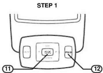
STEP 2 AM UP T P INVIS 12Step 1. To turn 'ON' - press and release the 'OK' button ⑪ and 'PWR' button ⑫ at the same time. The display will now include the setting temperature and the mode of operation.
Step 2. To turn 'OFF' - press the 'PWR' button ⑫ only.
Manual Temperature Mode
• Temperature can be set at any level.
- Time and day of week does not need to be programmed to operate.
text_image
STEP 1 ROOM 14 °C SET 22 °C T M 12:00 AM MO MANUAL UP T OK T DOWN PWR 13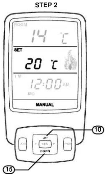
text_image
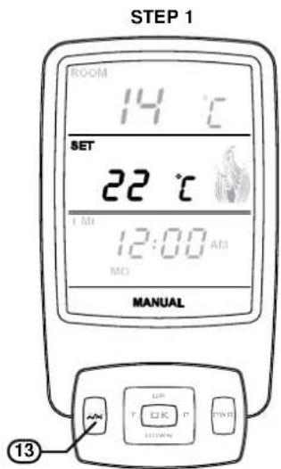
STEP 2 ROOM 14 °C SET 20 °C I M 12:00 AM MO MANUAL UP T OK P DOWN 10 15Step 1. With the controller turned 'ON', press and release the 'A/M' button ⑬ until the word 'MANUAL' appears on the LCD.
Step 2. Press press the 'UP' button ⑩ or 'DOWN' button ⑮ to increase or decrease the temperature in increments of 1^ C .
REMOTE / THERMOSTATIC CONTROLLED OPERATION
Automatic Timer Mode
- In automatic timer mode temperature is regulated to the programmed level and time.
• Time and day of week MUST BE set .
text_image
STEP 1 AUTO AVS UP OK DOWN 13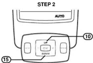
text_image
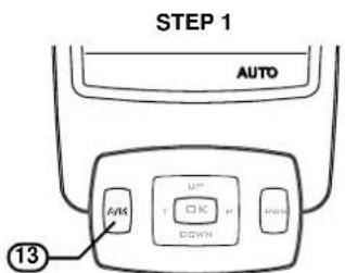
STEP 2 AUTO UP T OK H S554N 10 15Step 1. With the controller turned 'ON', press and release the 'A/M' button ⑬ until the word 'AUTO' appears on the LCD.
Step 2. At any time press the 'UP' button ⑩ or 'DOWN' button ⑮ to increase or decrease the temperature in increments of 1°C.
Flame Mode
• Temperature control is over ridden and the flame size can be set to any setting from F7 highest to F1 lowest.

When the fire first ignites it remains on highest flame for the first 60 seconds before changing to the selected flame height.
• Time and day of week does not need to be programmed.
text_image
STEP 1 SET F7 TIME 12:00 AM MD 17 13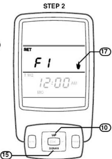
text_image
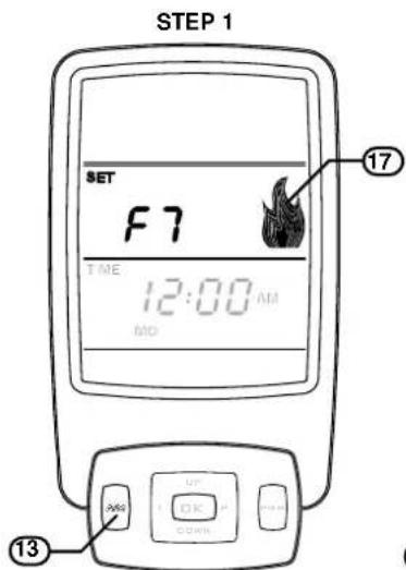
STEP 2 SET F1 TIME 12:00 AM MO 17 10 UP OK 55WH 15Step 1. With the controller turned 'ON', press and release the 'A/M' button ⑬ until the letter 'F' with a number and the flame symbol ⑭ appear on the LCD panel.
Step 2. Press the 'UP' button ⑩ or 'DOWN' button ⑮ to increase or decrease the flame height.

The fan speed automatically adjusts to the corresponding flame height. It is not able to be selected by the operator. See the flame table below for flame height to fan speed relationship.
| Flame Height 1 2 3 4 5 6 7 | |||||||
| Fan Speed | HIGH | LOW | LOW | LOW | HIGH | HIGH | HIGH |
Manually Overriding The Set Program
At any time, the temperature or fan speed may be adjusted 'UP' or 'DOWN' similarly to operating in "Manual Temperature Mode" on page 18.

However, whenever the thermostat changes to a new time period, the temperature will be set automatically according to that period's setting.
REMOTE / THERMOSTATIC CONTROLLED OPERATION
Flame Height And Fan Speed
The flame height and fan speed are not individually adjustable. Flame height and fan speeds are selected by the microprocessor according to the difference between the set temperature and the ambient temperature of the room. The fan speed automatically adjusts to the corresponding flame height. The fan speed is not able to be selected by the operator. When the heater is operated in 'Manual Temperature Mode' the flame height is automatically selected by the microprocessor to achieve and maintain the 'set' temperature. As an example, if the room is much colder than the 'set' temperature, the flame height and corresponding fan speed will be high. As the room heats up and gets close to the 'set' temperature the flame height and corresponding fan speed will revert to lower settings. When the heater is operated in 'Flame Mode' the flame height is set by the operator.
Flashing Small Flame Symbol 'ON'
The small flashing flame symbol 17 the RF controller display indicates the room temperature is within 0.5^ of set temperature.

Program Modes
The appliance can be programmed to operate during four separate periods in one day, resulting in a possible 28 operating periods per week. A weekday program can be set so the program is used Monday to Friday. Similarly, a weekend program can be set for Saturday to Sunday. The entire week can also have the same program.
| Factory default settings | If you do nothing to change the programming the following default settings would be available if you set it to automatic mode. | |||
| Time Period Start Time Temperature °C Suggested Time Period Settings | ||||
| Period 1 6:00 am 20°C - Morning | ||||
| Period 2 8:30 am 15°C - Day time | ||||
| Period 3 5:00 pm 21°C | - Evening | |||
| Period 4 | 10.30 pm | 15°C | - Night time | |
| To revert back to the default settings once you have reset the periods, in rapid succession press the following sequence of buttons ‘P’ - ‘T’ - ‘T’ - ‘DOWN’. | ||||
PROGRAMMING OF PROGRAM MODES
text_image
STEP 1 Pd TIME 10:25 AM MO PROG U T OK P PWR 16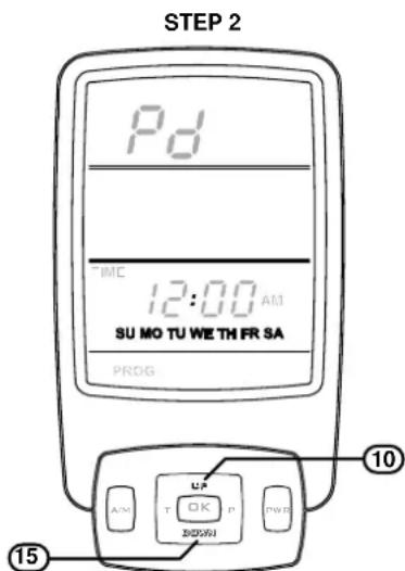
text_image
STEP 2 Pd TMC 12:00 AM SU MO TU WE TH FR SA PROG 10 15 A/M T OK P BODAYI PW ID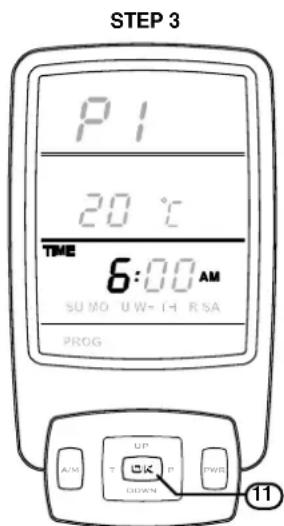
text_image
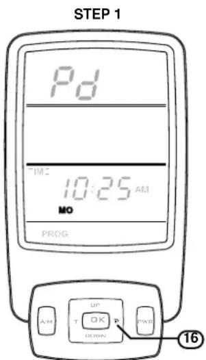
STEP 3 P1 20 °C TIME 6:00 AM SUMO UW-TH RSA PROG UP A/M T DOWN IP PWRL 11Step 1. With the controller 'OFF', press and hold the 'P' button 16 for approximately 2 seconds. The LCD will display 'PROG'. 'Pd' and the current time and the day 'MO' will flash.
Step 2. To select the day range press the 'UP' button ⑩ or 'DOWN' button ⑮ until the desired day range has been chosen the day ranges are as follows:
MO-TU WE TH-FR MO TU-WE TH FR SA SU-SU-SA SU-MO TU WE TH FR SA

Holding the 'UP' or 'DOWN' buttons for more than 2 seconds will scroll through the day ranges.
text_image
STEP 4 ROOM P1 20 °C TIME 7:80 AM SUMO "U WCT T" RA SA PROG 10 A/WWET UP DOWN 15 15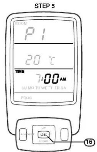
text_image
STEP 5 ROOM P1 20 °C TIME 7:00 AM SU MO TU WETI FR SA PROG UP A/W WET LIC DOWN 16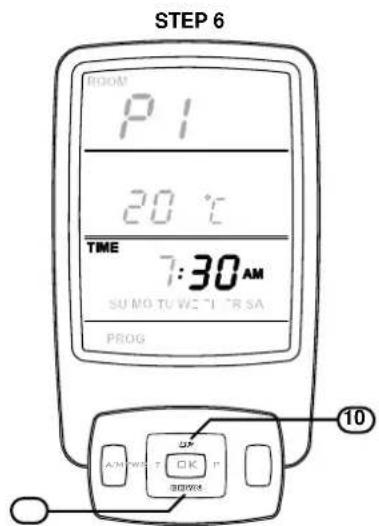
text_image
STEP 6 ROOM P1 20 °C TIME 7:30 AM SU MO TU WE T" TR SA PROG 10Step 3. Press the 'OK' button ⑪ to enter the selected day range. The LCD will display 'PROG'. 'P1' and the 'TIME' + 'HOUR' + 'AM' will flash.
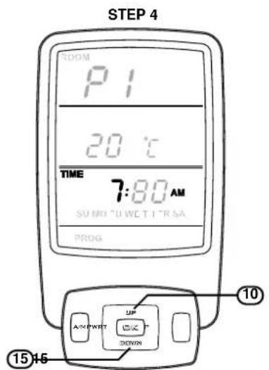
Step 4. To select the 'ON' hour for 'P1' push the 'UP' button ⑩ or 'DOWN' button ⑮ until the desired hour is chosen, note that AM or PM is chosen by cycling through the 12 hour range.
Step 5. Press the 'OK' button ⑪ to enter the selected hour and AM or PM. 'TIME' + 'MINUTES' + 'AM or PM' will flash.
Step 6. To select the 'ON' minutes for 'P1' push the 'UP' button ⑩ or 'DOWN' button ⑮ until the desired minute is chosen.
text_image
STEP 7 ROOM P1 SET 20 °C TIME 7:00 SUMO UW F R SA PROG M2 A M T T D K P B300K 16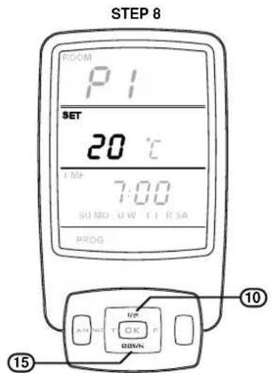
text_image
STEP 8 ROOM P1 SET 20 ℃ TIME 7:00 SUMO UW T1 RSA PROG 10 15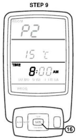
text_image
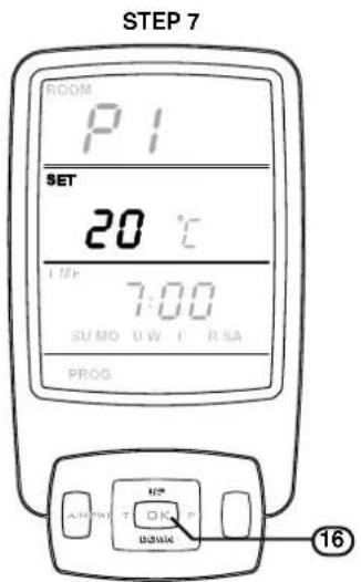
STEP 9 ROOM P2 15 °C TIME 8:00 AM SUMO UWI IIRSA PROG AM/WRT LW GOS DOWN 16Step 7. Press the 'OK' button ⑪ to enter the 'ON' minutes. 'SET' + 'TEMPERATUTRE DIGITS' will flash.
Step 8. To select the 'ON' temperature for 'P1' push the 'UP' button ⑩ or 'DOWN' button ⑮ until the desired temperature is chosen.
Step 9. Press the 'OK' button ⑪ to enter the selected temperature. The LCD will display 'PROG'. 'P2' and the 'TIME' + 'HOUR' + 'AM' will flash, this completes the programming for the 'P1 - ON' period. Repeat steps 3 through 9 for 'PROG'. 'P2 - OFF', 'P3 - ON' and 'P4' 'OFF' periods.
CARE AND MAINTENANCE
Your heater needs very little maintenance, but the following information will help you to keep it looking good and working efficiently.

DO NOT attempt to clean the heater while the appliance is hot or operating.
All parts of the heater can be cleaned using a soft, damp cloth.
DO NOT use solvents or abrasives to clean any parts.
DO NOT spray aerosols in the vicinity of the heater whilst in operation.
DO NOT place articles on or against this heater.
DO NOT store flammable materials near this heater.
SERVICE
Rinnai recommend that this appliance and installation be inspected and serviced every 2 years or more frequently.
If the power supply cord or any other component of the heater are damaged, they must be replaced by Rinnai or a suitably qualified person.
Any service or repair work should only be carried out by an authorised person. Rinnai has service and spare parts departments nationally. See back cover for contact details.

Service calls for general cleaning, maintenance and wear and tear are not necessarily covered under the warranty. Service calls of this nature may be chargeable.
Faults caused by insufficient gas supply, gas quality, installation errors or operation errors are not covered by the Rinnai warranty. Refer to separate Warranty Card for details.
TROUBLE SHOOTING
General Operation Characteristics

Before asking for a service call please check the following table as these characteristics are part of the normal operation of the appliance and do not indicate a fault.
CHARACTERISTIC EXPLANATION
| At ignition: | |
| Warm air does not start when the burner lights. | The fan is started automatically after a short delay. This is to allow the heat exchanger to warm up, helping to avoid cold draughts.This is normal operation. |
| Smoke or strange smells are produced on the first start up after installation. | This is caused by grease, oil or dust on the heat exchanger.This is to be expected and will cease after a short time. |
| Sharp clicking noises at ignition, or when the unit thermostat modulates to a lower or higher setting, or shuts down. | This is simply expansion and contraction noise from the heat exchanger.This is a normal operation sound. |
| During combustion: | |
| Dull clunking noise when the thermostat operates. | This is the sound of the solenoid gas valves opening and closing to regulate the gas flow.These are normal operation noises. |
| When the appliance is turned off: | |
| Convection fan continues to run after turning ‘OFF’. | This is to remove residual heat from the heat exchanger and stops once the appliance cools sufficiently. |
CARE AND MAINTENANCE
TROUBLE SHOOTING CHECKLIST
Use the following chart to help determine whether a service call is required, however if you are unsure about the way your heater is operating, contact Rinnai or your local agent.
| Probable Cause\Fault Condition→ | Burners fail to ignite | Smell of gas | Fan Not Working | Minor soot deposits | Severe sooting | Glass, Condensating | Glass, Streaky lines | *Remote not working | Fault Condition←Simplest Possible Remedy↓ |
| Not plugged in or turned off Plug in power cord and turn power 'ON'. | |||||||||
| Mains power failure Re-ignition, when power restored. | |||||||||
| (Initial Install) Air in gas pipe Installer to large air from gas supply. | |||||||||
| Air in hose Repeat Ignition procedure. | ● | ||||||||
| Ignition failure Repeat Ignition procedure. | ● | ||||||||
| Flat battery for remote control * | ● | ● | Replace remote control battery. | ||||||
| Gas supply turned off Turn gas supply on the meter or cylinder. | |||||||||
| Gas escape Isolate gas supply, call Rinnai. | ● | ||||||||
| Inadequate flue system Call Rinnai. | ● | ● | |||||||
| Insufficient gas pressure Call Rinnai. | ● | ● | |||||||
| Log Misalignment Call Rinnai. | ● | ||||||||
| Normal operation No action is required | ● | ● | |||||||
| Normal operation | ● | Fan not working - fan automatically comes on after 4 minutes not heat switch activated. | |||||||
| Normal operation Allow heater to warm up. | ● | ||||||||
| Heat switch not activated Allow heater to run on high for 4 minutes | |||||||||
| Possible fan fault | ● | Call Rinnai. | |||||||
| Controller display blank | ● | ● | Replace batteries. | ||||||
| Control Panel Operation ** | ● | ● | Refer to page 12 for solution. | ||||||
| Controller Not Synchronised Refer to page 14 for solution. | ● | ||||||||
* Only applicable when optional remote controller is used.
** Only applicable if the remote controller is programmed.
ABNORMAL FLAME PATTERN
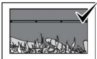
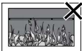
Each Rinnai Flame Fire heater has a distinct flame pattern. The flame should look the same every time you start your heater, after an initial warm up period of approximately 15 minutes.
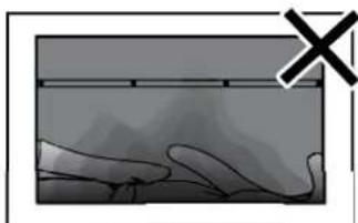
Abnormal flame performance and/or pattern can indicate a problem with your heater, such as blocked gas injectors, incorrectly installed / inadequate flue system or the artificial logs/burn media may have shifted from when the heater was first installed.
There are some warning signs that could indicate a problem. If any of the signs below occur, please contact Rinnai.
natural_image
Diagram showing a geological or material cross-section with layered structures and a downward arrow (no text or symbols)NORMAL FLAME PATTERN
natural_image
Illustration of a fire with smoke rising from a firehole (no text or symbols)ABNORMAL FLAME PATTERN
natural_image
Illustration of a hand holding a device with a 'X' symbol in the corner (no text or symbols on the device itself)SOOT BUILD UP
Key signs of abnormal flame performance:
- Appliance turns 'OFF' soon after start up and does not relight.
- Flame appears overly orange-yellow.
- Flame appears either very short or very long.
- Flame only burns part way across the burner.
- Severe soot building up on the inside of the glass and logs.
• Continuous unusual smell from the appliance.
• Continued difficulty or delay in establishing a flame.

Be advised that appliances incorporating a live fuel effect, and designed to operate with luminous flames, may exhibit slight carbon deposition, this is normal operation.
NOTES
TABLE OF CONTENTS - INSTALLATION
SPECIFICATIONS....26
GENERAL SPECIFICATIONS 26
DIMENSIONS 27
HEATER LOCATION.... 28
GENERAL LOCATION INFORMATION....28
TV AND ORNAMENTATION WARNING 28
ENCLOSURE REQUIREMENTS 29
ENCLOSURE DIMENSIONS 29
HEATER ENGINE - GENERAL INSTALLATION 30
GAS SUPPLY 30
ELECTRICAL SUPPLY 31
FLUEING 32
MASONRY FLUE INSTALLATION.... 33
OPEN INSTALLATION METHOD 33
HEATER ENGINE INSTALLATION - MASONRY.... 34
MASONRY INSTALLATION OVERVIEW 34
MASONRY INSTALLATION - DETAIL 34
HEATER ENGINE INSTALLATION - ZERO CLEARANCE 36
ZERO CLEARANCE INSTALLATION OVERVIEW 36
ZERO CLEARANCE INSTALLATION - DETAIL 36
HEATER ENGINE INSTALLATION - CONSOLE 39
FREESTANDING CONSOLE INSTALLATION OVERVIEW 39
FREESTANDING CONSOLE INSTALLATION - DETAIL 39
HEATER ENGINE INSTALLATION - PLINTH 42
FREESTANDING PLINTH INSTALLATION OVERVIEW 42
FREESTANDING PLINTH INSTALLATION - DETAIL 42
COMPLETING HEATER INSTALLATION 45
PREPARING FOR COMMISSIONING 45
COMMISSIONING THE APPLIANCE 49
ATTACHING FASCIA ASSEMBLY 50
ATTACHING DRESS GUARD TO CLASSIC FASCIA ASSEMBLY 51
ABNORMAL FLAME PATTERN....51
WIRING DIAGRAM....52
CHECKLIST 53
INSTALLATION AND COMMISSIONING CHECKLIST 53
CONTACT INFORMATION....56

THIS APPLIANCE MUST BE INSTALLED, SERVICED AND REPAIRED BY AN AUTHORISED PERSON.

SPECIFICATIONS
GENERAL SPECIFICATIONS
| Model RIB2311MN/A | RIB2311ML/A |
| Model Name Sapphire Gas Log Flame Fire | |
| Features Inbuilt or Freestanding Gas Space | HeaterBurning log effectGlass frontConvection Fan, top warm air outletGlass dress guard (standard model)Mesh dress guard (classic model) |
| Installation Inbuilt Masonry, Inbuilt Zero Clearance and Freestanding options | |
| Combustion Method Bunsen type burner | |
| Flue - Masonry (if required)Flue - Freestanding & zero clearance | FlexiLiner diameter. 100 mmTwin skinned diameter. 100mm x diameter. 150mm outer |
| Convection Fan Double drum. 160mm x 180mm - 2 speed - Centrifugal | |
| Gas connection G 1/2" flared male | |
| Gas type NG, Propane Universal LPG | |
| Ignition Continuous Spark Electronic Ignition | |
| Input / Output Refer data plate and energy rating label on appliance | |
| Power Consumption | High 50 W, Standby < 3.0 W1500 mm cord is supplied with a 3 pin plug |
| Safety Devices | Overheat SwitchElectrical FuseFlame Failure Sensing System (FFD)Power Failure ProtectionGas Lock-out (1 minute after attempted restart) |
| Temperature Control | Thermostatic, temperature control range 7 - 32°C |
| Glass - PrimaryGlass - SecondaryGlass seal material | Ceramic GlassTempered GlassWoven fibreglass chord - Hytex® 1000 by mid Mountain USA |
| Weight (Engine Only) | 60 Kg - "uncrated" - no Flue |
| Operation | Push button control panel or via optional wireless remote/thermostatic control |

For other appliance specifications refer to appliance data plate.
DIMENSIONS

text_image
A B F C D MASONRY J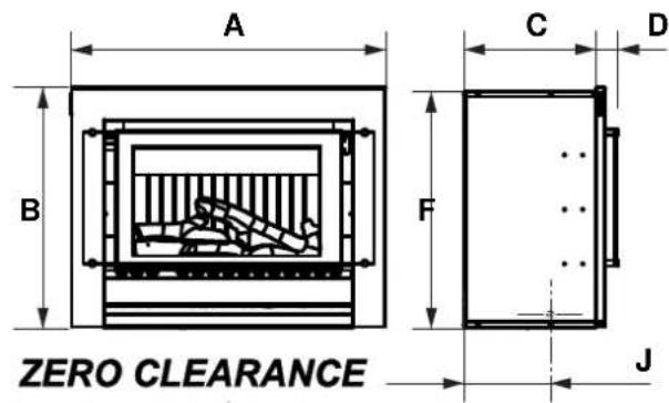
text_image
A B C D F ZERO CLEARANCE J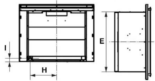
text_image
I H E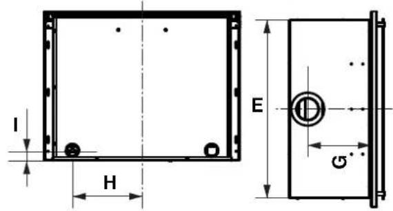
text_image
I H E G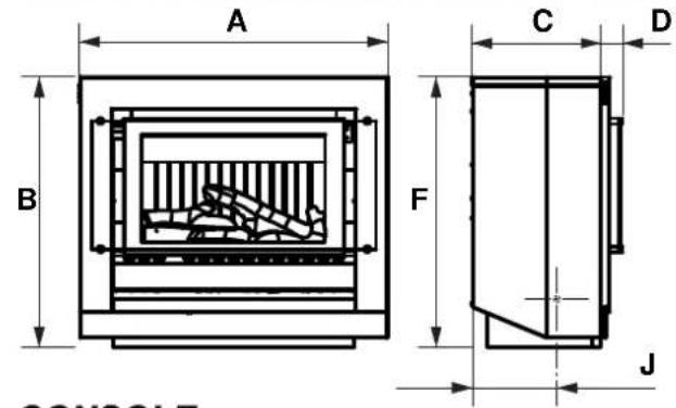
text_image
A B C D F J CONSOY 5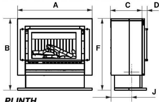
text_image
A B F C D J PLINTH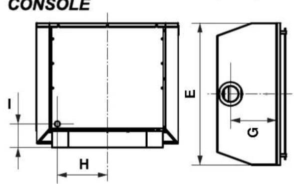
text_image
CONSOLE I H E G
text_image
I H E GNote: Standard model fascia shown for illustrative purposes
| MODEL | External Dimensions - Flue Centre Gas Connection | ||||||||||
| A | B | C | D | E | F | G | H | I | |||
| Masonry | Standard 865 | mm 660m | 359mm | 62mm 69 | 1mm 589 | mm - 305mm | 45mm | 235mm | |||
| Classic 865m | 701mm | 359mm | 76mm 691 | mm 589mm | mm - 305mm | 45mm | 235mm | ||||
| Zero Clearance | Standard 865 | mm 660m | 363mm | 62mm 79 | 5mm 650 | mm 280mm | 305mm | 45mm 240mm | |||
| Classic 865m | 701mm | 363mm | 76mm 795 | mm 650mm | mm 280mm | 305mm | 45mm 240mm | ||||
| Console 865mm 760m | 363mm | 62mm 865 | mm 760 | mm 280mm | 305mm | 144mm 235mm | |||||
| Plinth 865mm 837mm | 363mm | 62mm 865 | mm 837m | mm 280mm | 305mm | 219mm 235mm | |||||
HEATER LOCATION
GENERAL LOCATION INFORMATION
- When positioning the heater, the main variables governing the location are Flueing and Warm Air Distribution.
- This heater must not be installed where curtains or other combustible materials could come into contact with it. In some cases curtains may need restraining. Refer to page 5 and page 6 for additional safety consideration.
- Mantles and surrounds can be added to compliment the design provided that they conform to the clearances shown in the diagrams below.
- The minimum clearance from the edge of the appliance is 400 mm. The depth of the mantle/surrounds at the minimum clearance may not exceed 150 mm.
- An additional 100 mm of clearance is required for every extra 50 mm of mantle depth, i.e. for a 200 mm deep mantle the clearance is 500 mm (as shown below).
text_image
INBUILT MODELS Maximum mantle depth (at 400mm) may only be 150mm Note: Standard model fascia shown for illustrative purposes FREE-STANDING MODELS 75mm 10mm 10m m 400mm 400mm 400mm 1000mm 1000mm 75mm 750mmTV AND ORNAMENTATION WARNING

INSTALLATION OF TV OR ORNAMENTATION ABOVE THE HEATER
The installation of electrical appliances above and in the vicinity of the heater such as, but not limited to, Plasma TV, LCD TV, Home Theatre Screens, Speakers, etc must comply with their manufacturers' instructions.
It is the responsibility of the installer/end-user to check the installation instructions of these items and to ensure the location is suitable.
This caution also extends to, but is not limited to, ornaments such as: Paintings, Prints, Photographs, Tapestries, Mirrors, Stuffed Animals, etc.
Please note the recommended clearances as per the diagram above.
The temperature of the wall surface directly above the appliance may be elevated and may discolour paint finishes or distort vinyl wall coverings. For durability of surfaces you should contact the relevant manufacturer for their specification.

Use either a shelf or mantle below the TV or ornament or alternately you can construct a recess to mount TV or ornament in.
Check the manufacturers installation instructions for these items and ensure the recess is suitable.

Rinnai does not take any responsibility for any damage occurring to any items installed above and in the vicinity of the heater.
HEATER LOCATION
ENCLOSURE REQUIREMENTS
Masonry Fireplace
The appliance must be positioned within the fireplace on a flat level surface.
If the appliance is elevated from the ground within the structure, a base must be constructed using suitable material with supporting joists capable of supporting a minimum of 1.5 times the weight of the appliance.
Zero Clearance In-built installation
Framework of the installation must conform to local building codes. Non-combustible materials need not be used. If the appliance is elevated from the ground within the structure, a base must be constructed using suitable material with supporting joists capable of supporting a minimum of 1.5 times the weight of the appliance.

AS 5601 “GAS INSTALLATIONS” requires that flue components be supported independently of the appliance.
ENCLOSURE DIMENSIONS
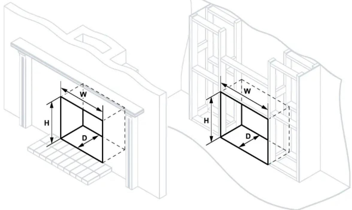
Enclosure dimensions are shown below. The enclosure dimensions specified are critical to the successful installation of this appliance and must be strictly adhered to.
MASONRY INSTALLATION ZERO CLEARANCE INSTALLATION
text_image
Technical diagram showing two 3D structural views with dimension labels W, H, and D for architectural or engineering design.| All dimensions are minimums and are in mm | |||
| MODEL Height (H) Width | (W) Depth (D) | ||
| Masonry 600 695 370 | |||
| Zero Clearance 650 800 | 420(read caution below) | ||

For clarity the consumer piping gas supply, electrical connections and some construction details have been omitted. Refer to “GAS SUPPLY” on page 30 and “ELECTRICAL SUPPLY” on page 31 for details.
When preparing a cavity / frame for a zero clearance installation the total cavity depth MUST also include the thickness of the external cladding, as the zero clearance box MUST BE installed flush with the cladding surface. Failure to do this will cause misalignment of the flue systems.
HEATER ENGINE - GENERAL INSTALLATION
GAS SUPPLY

Gas pipe sizing must consider the gas input to this appliance as well as all other gas appliances in the premises. The gas meter and regulator must be specified for the total gas rate. A suitable sizing chart such as the one in AS 5601 should be used.

Confirm correct gas type (see labels located on top or rear panels). Refer to local gas authority for confirmation of gas type if you are in doubt.
Installation of consumer piping
The gas supply (consumer piping), termination is inside the heater and enters through the rear of the appliance. Refer to the dimensional drawings on page 27 for appliance gas inlet location and other relevant dimensions.
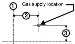
Mark off the location for the vertical centre line of the heater enclosure (inbuilt installations) or heater (freestanding installations).
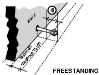
To the right of the vertical centre line ① mark off both the vertical and horizontal ③ location for the gas supply penetration (consumer piping). For measurements refer to the Gas Supply Dimension Table below.
Inbuilt Models: The length of the gas supply (consumer piping) termination ④ is measured from the front of the enclosure.
Freestanding Models: The length of the gas supply (consumer piping) termination ④ is measured from the back of the heater plus 95mm.

For freestanding models the minimum clearance of 75mm from the wall must be observed.
At the minimum clearance the total length of the consumer pipe is 170mm (75mm + 95mm)
text_image
Gas supply location ① ② ③
text_image
REAR OF ENCLOSURE ④ FRONT OF ENCLOSURE INBUILTGas Supply Dimension Table
| Inbuilt Freestanding | ||||
| Masonry Zero | Clearance Console | le Plinth | ||
| 2 | 305mm to right of appliance centre-line | 305mm to right of appliance centre-line | 305mm to right of appliance centre-line | 305mm to right of appliance centre-line |
| 3 | 45mm from base of enclosure | 45mm from base of enclosure | 144mm from floor level | 219mm from floor level |
| 4 | Consumer piping to be terminated 265mm from the front of enclosure | Consumer piping to be terminated 265mm from the front of enclosure | Consumer piping to be terminated at wall clearance plus 95mm | Consumer piping to be terminated at wall clearance plus 95mm |
Once the consumer piping has been terminated to the above requirements the supplied flexible gas connection ⑤ may then be fitted.
Purging Gas Supply
Foreign materials and debris such as swarf, filings, etc. MUST BE purged/removed from the gas supply, failure to do so may cause damage to the gas control valve causing it to malfunction.
text_image
WALL 4 diammum close 150 mm FREESTANDING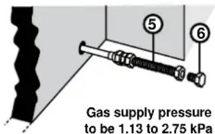
text_image
Gas supply pressure to be 1.13 to 2.75 kPaLeak Testing The Connection
With the supplied plug ⑥ inserted into the end of the flexible gas connection leak test all joints.

Use a soapy solution to test all gas connections. If a leak is present bubbles will form at the leak point. When finished remove any residue with a rag. Prevent any soapy solution from coming in contact with electrical components.
HEATER ENGINE - GENERAL INSTALLATION
ELECTRICAL SUPPLY
If a power point is used it MUST BE 240 V, rated at 10A and MUST BE earthed. This power point MUST NOT be located above the heater. Alternatively the appliance can be direct wired if the power supply is to be concealed.
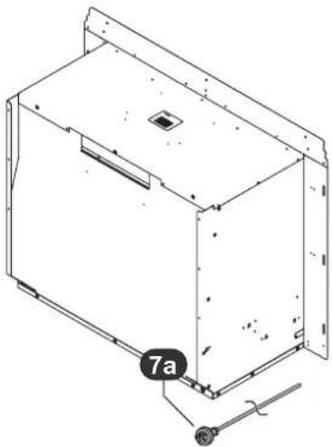
The heater engine is fitted with a 1.5 m power cord and three pin plug 7a which exits the appliance from the rear panel at the lower left.
Direct Wired Installations
Alternatively the appliance can be direct wired if the power supply is to be concealed.

A qualified electrician will need to be consulted where a direct wired installation is required. Any such installation must comply with the requirements of AS 5601, AS 3000 and any other relevant local regulations.
natural_image
Technical line drawing of a rectangular electronic device with mounting bracket and labeled component '7a' (no text or symbols beyond label)Using Existing Externally Mounted Power Points on Inbuilt Installations
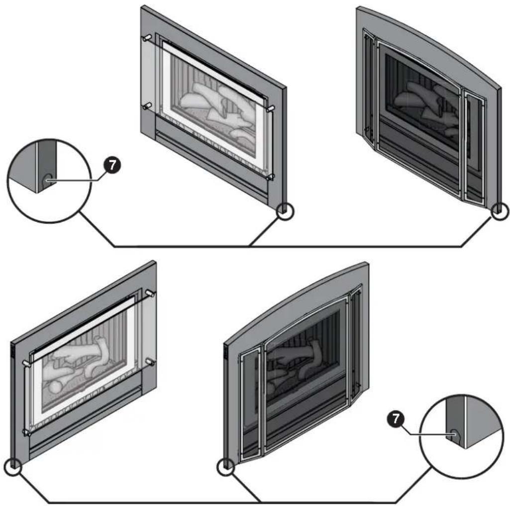
If you already have an existing wall plug located outside of the intended fireplace or enclosure you may redirect the power cord and plug assembly through the front panel. With Fascia assembly removed, simply redirect the cord and plug assembly with grommet from the rear of the unit, underneath the fire-box to the front of the unit, (either left or right).
Carefully remove the pre-punched sheet metal 'knock-out' section located in the lower left or right edge ⑦ of the Fascia Assembly. Refit the cord and plug assembly to the Fascia assembly ensuring the grommet is fitted to the sheet metal. Excess cord may be left in the cavity below the fire box. DO NOT coil excess cord.
text_image
Diagram illustrating the installation steps of a fire-resistant cabinet, showing front and side views with numbered annotations.HEATER ENGINE - GENERAL INSTALLATION
FLUEING

The following diagrams illustrate the flue installation options that are available for the Sapphire flame. Only the genuine Rinnai Flamefire (FLF) flue is certified as part of the Rinnai Sapphire space heaters.
Only an authorised person must install, service and remove the Rinnai Sapphire space heater & flue system.
Only the flue system components described in the ‘Flueing Installation Manual For Rinnai Flamefire Heaters’ that is provided with the flue kit must be used.
Components that are not described in that manual, whether manufactured by Rinnai or otherwise, are not compatible and must not be used.
Rinnai appliance warranty conditions may be voided if non Rinnai flue components are fitted.
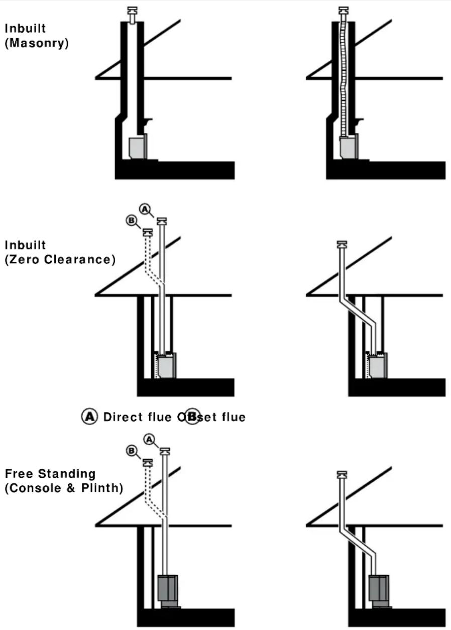
Install the Rinnai rigid flue system components in accordance with the 'Flueing Installation Manual For Rinnai Flamefire Heaters' that are provided with the flue kit.

For masonry installation details refer to "MASONRY FLUE INSTALLATION" on page 33.
MASONRY FLUE INSTALLATION
Two masonry flue installation options available. These are Open Chimney and Lined Chimney.
An ‘Open Chimney’ installation uses the natural draft properties of a sound chimney along with the addition of an approved chimney plate and cowl to provide the flueing for the heater.
A ‘Lined Chimney’ installation is used when the existing chimney condition is inadequate for an Open Chimney’ installation and uses a Rinnai Flexiliner (flexible) flue system, chimney plate and cowl to provide the flueing for the heater.
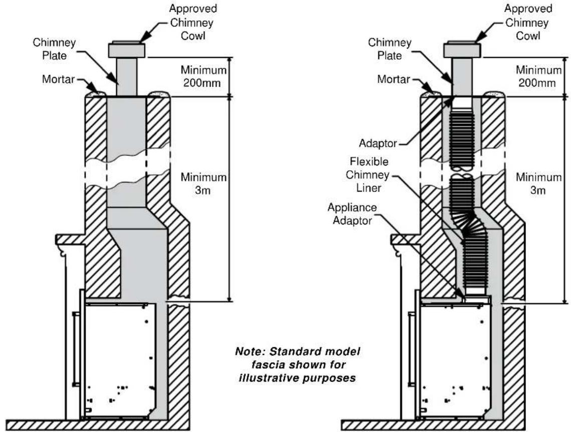
text_image
Approved Chimney Cowl Chimney Plate Mortar Minimum 200mm Minimum 3m Approved Chimney Cowl Chimney Plate Mortar Minimum 200mm Adaptor Flexible Chimney Liner Appliance Adaptor Minimum 3m Note: Standard model fascia shown for illustrative purposesOpen Chimney Installation Lined Chimney Installation
OPEN INSTALLATION METHOD
The chimney must be physically checked first and must meet the following set criteria along with local regulations. Failure to meet these criteria will not only void the product warranty but may affect the performance of the heater and may void the warranty.
Chimney Criteria For Open Installation
- All loose/broken bricks must be replaced or repaired ensuring the chimney is of sound construction and does not leak in accordance with AS 5601.
- Any under floor air supply to the fireplace must be completely sealed off to prevent secondary air draw.
- Total chimney height MUST NOT be less than 3 metres and flue cowl must terminate above the chimney in accordance with AS5601.
- The chimney must be swept clean and be free of soot and creosote that may have built up if previously used for a solid fuel fire.
- The hearth surface must be flat and level to support the entire heater. If the heater is not properly supported noise and vibration may result.

In a masonry fireplace, use a slurry of sand and cement to level the base as required.
HEATER ENGINE INSTALLATION - MASONRY
MASONRY INSTALLATION OVERVIEW

Read this manual thoroughly and gain a full understanding of the requirements before undertaking installation.
Ensure gas supply to heater is turned off for the first stages of this instruction.
Step 1. Prepare Site - p.34
Step 7. Insert Heater Engine Into Fireplace - p.35
Step 2. Unpack The Heater Engine - p.34
Step 8. Securing The Heater Engine - p.35
Step 3. Preparing Heater Engine - p.34
Step 9. Connecting Gas - p.35
Step 4. Positioning the Heater Engine - p.35
Step 10. Leak Testing - p.35
Step 5. Connect Electrical Supply - p.35
Step 11. Completing Heater Installation - p.35
Step 6. Prepare Gas Supply - p.35
MASONRY INSTALLATION - DETAIL
Step 1. Prepare Site

Ensure the intended enclosure meets the requirements of the dimensions as stipulated in “ENCLOSURE REQUIREMENTS” on page 29 and that gas and electrical supplies have been prepared in accordance with the dimensions stipulated in “GAS SUPPLY” on page 30 and “ELECTRICAL SUPPLY” on page 31.
Step 2. Unpack The Heater Engine
The heater engine is supplied in one carton, check to ensure you have all contents as listed on "BEFORE YOU START" on page 4 at the start of this manual before proceeding.
Carefully remove carton by removing the straps and lifting the carton off the appliance. Remove all packaging materials and check all components for damage. If ANY damage is evident DO NOT install or operate this appliance. Contact your supplier for advice.

Retain the cardboard carton for use in the “Positioning the Heater Engine” on page 35.
Before installing the heater, check it is labelled for the correct gas type, (refer to the gas type label on the top body panel of the heater). Refer to the local gas authority for confirmation of gas type if you are in doubt.
Step 3. Preparing Heater Engine
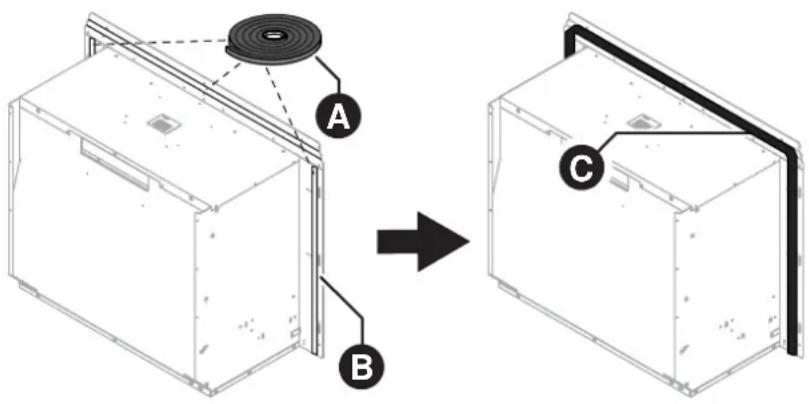
Attach the adhesive backed foam sealing strip A supplied to rear face of the fascia assembly mounting panel B Ensure the seal is stuck to the Fascia Assembly mounting panel at approximately 30mm from the top edge C.
The foam strip is intended to form a seal between the heater and the fireplace brickwork. If an adequate seal cannot be formed then another means of sealing must then be used. (e.g. non combustible insulation or heat resistant silicon).
text_image
Diagram showing a device assembly process with labeled components A, B, and C, indicating a transformation or assembly step.HEATER ENGINE INSTALLATION - MASONRY
Step 4. Positioning the Heater Engine
Place the heater engine in front of the fireplace enclosure.

A panel from the cardboard packing carton placed on the floor underneath the heater will help prevent possible damage to flooring.
Step 5. Connect Electrical Supply
Plug in the 3 pin connector if electrical connections inside the fireplace.
Step 6. Prepare Gas Supply
Remove the threaded brass plug from the S/S flexi pipe consumer gas supply pipe.
Step 7. Insert Heater Engine Into Fireplace
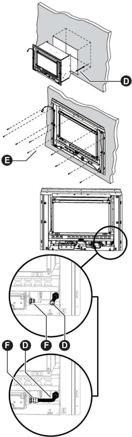
Carefully move the heater engine into the fireplace ensuring the gas supply pipe and fittings D ed into the rear access hole.

Take care that the electrical cord does not bunch up or get pinched behind the heater engine.
Step 8. Securing The Heater Engine
Fasten the heater to the masonry work using appropriate fasteners (not supplied) using the three holes across the top of the fascia assembly mounting panel and in at least 2 of the holes on each side of the side panels as shown E
Step 9. Connecting Gas
Firmly grasp the S/S flexi pipe D and bend at 90° approximately mid way to line up with the gas control valve inlet F en attach pipe to gas control valve and tighten.
Step 10. Leak Testing
Turn gas back ON and leak test appliance connection.

Use a soapy solution to test all gas connections. If a leak is present bubbles will form at the leak point. When finished remove any residue with a rag. Prevent any soapy solution from coming in contact with electrical components.
Step 11. Completing Heater Installation
Go to "COMPLETING HEATER INSTALLATION" on page 45.
text_image
Technical diagram showing exploded view of a server rack with labeled components and internal layout viewsZERO CLEARANCE INSTALLATION OVERVIEW

Read this manual thoroughly and gain a full understanding of the requirements before undertaking installation.
Ensure gas supply to heater is turned off for the first stages of this instruction.
Step 1. Prepare Site - p.36
Step 8. Prepare Gas Supply - p.38
Step 2. Assemble Zero Clearance Box. - p.36
Step 9. Insert Heater Engine Into Fireplace - p.38
Step 3. Fitting Zero Clearance Box Into Cavity - p.37
Step 10. Securing The Heater Engine - p.38
Step 4. Unpack The Heater Engine - p.37
Step 11. Connecting Gas - p.38
Step 5. Preparing Heater Engine - p.37
Step 12. Leak Testing - p.38
Step 6. Positioning the Heater Engine - p.38
Step 13. Completing Heater Installation - p.38
Step 7. Connect Electrical Supply - p.38
ZERO CLEARANCE INSTALLATION - DETAIL
Step 1. Prepare Site

Ensure the intended enclosure meets the requirements of the dimensions as stipulated in "ENCLOSURE REQUIREMENTS" on page 29 and that gas and electrical supplies have been prepared in accordance with the dimensions stipulated in "GAS SUPPLY" on page 30 and "ELECTRICAL SUPPLY" on page 31.
Ensure there are no wall studs, noggins, ceiling joists, wiring or other obstruction within the wall and or ceiling cavity where the flue is proposed to penetrate.
Step 2. Assemble Zero Clearance Box.
Carefully remove the contents from the carton and check to ensure you have all contents as listed in "BEFORE YOU START" on page 4. If ANY damage is evident or parts are missing DO NOT assemble the zero clearance box and contact your supplier for advice

Flue guide rails and pop rivets supplied with Zero Clearance kit, part number R2340.
text_image
I A B C B1 B2 D D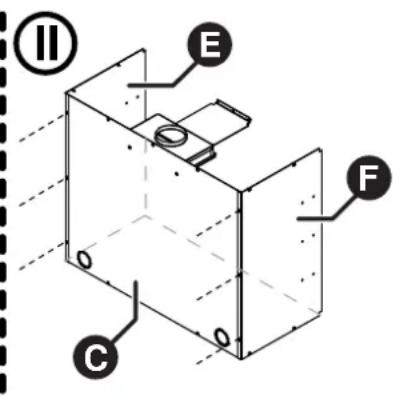
text_image
(II) E F C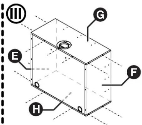
text_image
III G E F HI. Assemble the transition box halves
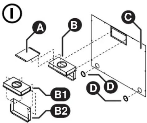
B1 and B2 cure together with 4 x screws (supplied).
Attach the guide plate A to the transition box assembly B and secure with two pop-rivets (supplied).
Drill 2 x ∅ 3.2mm holes in the pre pressed location dimples on the back of the transition box and fit the transition box assembly A B to the back panel Cnd secure with the two screws (supplied).
Fit the two plastic grommets D to the gas and electrical access holes of back panel . C
II. Attach the two side panels
E & F the back panel
aC secure with six screws (suppled).
III. Attach top panel G to the back panel and secure with three screws (supplied
© aligning the
e flue outlet hole to the rear ov
Next secure the top panel Ⓖ the side panels
E & Fith four screws (supplied).
Attach base panel Ⓗ the back panel
a© secure with two screws (supplied).
Then secure the base panel Ⓗ the side panels
E & F ith four screws (supplied).
Ensure flue has been installed as per 'Flueing Installation Manual For Rinnai Flamefire Heaters'.
HEATER ENGINE INSTALLATION - ZERO CLEARANCE
Step 3. Fitting Zero Clearance Box Into Cavity
Slide zero clearance box assembly into the cavity, ensuring the gas and electricity supplies are accessible.

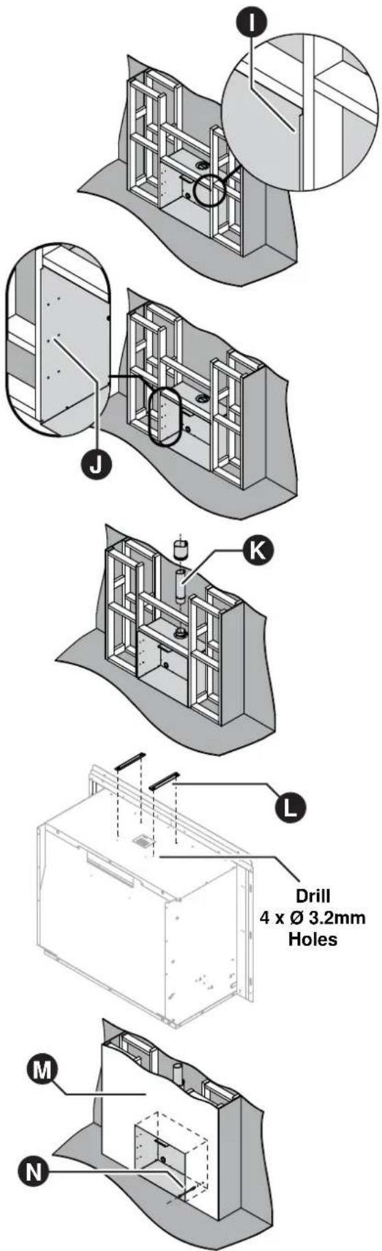
When preparing a cavity / frame for a zero clearance installation the total cavity depth MUST also include the thickness of the external cladding ① as the zero clearance box MUST BE installed flush with the cladding surface, failure to do this will cause misalignment of the flueing.
Secure the zero clearance into the cavity ⚠ with appropriate fasteners (not supplied).
Install the Rinnai rigid flue system components Kin accordance with the 'Flueing Installation Manual For Rinnai Flamefire Heaters' that is provided with the flue kit.

Ensure there are no wall studs, noggins, ceiling joists, wiring or other obstruction within the wall and or ceiling cavity where the flue is proposed to penetrate.
Step 4. Unpack The Heater Engine
The heater engine is supplied in one carton, check to ensure you have all contents as listed on "BEFORE YOU START" on page 5 at the start of this manual before proceeding.
Remove carton by removing the straps and carefully lifting the carton off the appliance. Remove all packaging materials and check all components for damage. If ANY damage is evident DO NOT install or operate this appliance. Contact your supplier for advice.

Retain the card board carton for use in the "Positioning the Heater Engine" on page 38.
Before installing the heater, check it is labelled for the correct gas type, (refer to the gas type label on the top body panel of the heater). Refer to the local gas authority for confirmation of gas type if you are in doubt.
Step 5. Preparing Heater Engine
Drill 4 x ∅ 3.2mm holes in the pre pressed location dimples in the top panel of the heater. Then attach the flue guide rails using these holes with four screws (supplied).

Flue guide rails and pop rivets supplied with Zero Clearance kit, part number R2340.
Before proceeding any further with the heater engine installation ensure the cladding for the front of the enclosure has been fitted M.
text_image
I J K L Drill 4 x Ø 3.2mm Holes M NHEATER ENGINE INSTALLATION - ZERO CLEARANCE
Step 6. Positioning the Heater Engine
Place the heater engine in front of the zero clearance box / cavity.

A panel from the cardboard packing carton placed on the floor underneath the heater engine will help prevent possible damage to flooring.
Step 7. Connect Electrical Supply
Plug in 3 pin connector if electrical connections are inside the fireplace.
Step 8. Prepare Gas Supply
Remove the threaded brass plug from the S/S flexi pipe consumer gas supply pipe.
Step 9. Insert Heater Engine Into Fireplace
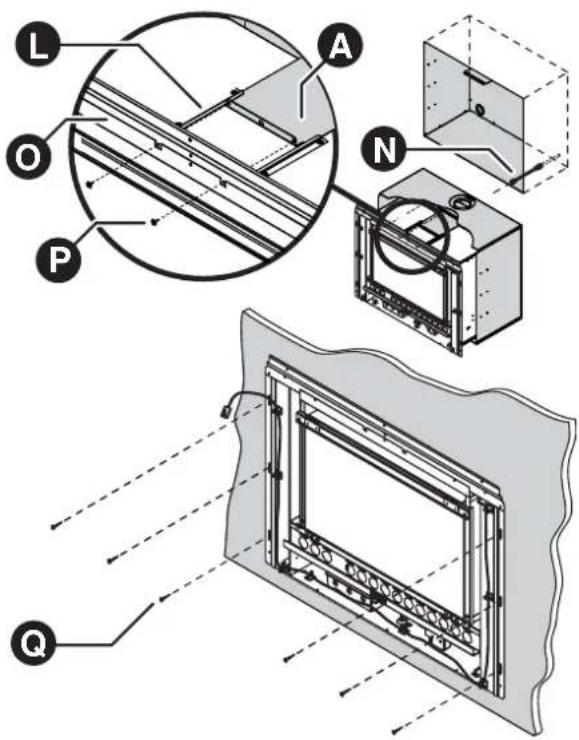
Carefully move the heater engine into the zero clearance box ensuring the gas supply pipe and fittings N feed into the rear access hole.

Take care that the electrical cord does not bunch up or get pinched behind the heater engine.
Align the guide rails Lith the guide plate a A slide the heater engine in until the guide plate A is fully home against the rear of the fascia assembly mounting panel O
Step 10. Securing The Heater Engine
Secure the guide plate A to fascia assembly mounting panel O with two screws (S P applied).
Fasten the heater engine to cladding surface using appropriate fasteners (not supplied) in at least 4 positions as shown ☐
Step 11. Connecting Gas
Firmly grasp the S/S flexi pipe N and bend at 90° approximately mid way to line up with the gas control valve inlet R then attach pipe to gas control valve and tighten.
Step 12. Leak Testing
Turn gas back ON and leak test appliance connection.

Use a soapy solution to test all gas connections. If a leak is present bubbles will form at the leak point. When finished remove any residue with a rag. Prevent any soapy solution from coming in contact with electrical components.
Step 13. Completing Heater Installation
Go to "COMPLETING HEATER INSTALLATION" on page 45.
text_image
Technical diagram illustrating the internal structure and assembly of a mechanical or electrical component, labeled with letters A, L, O, P, N, Q.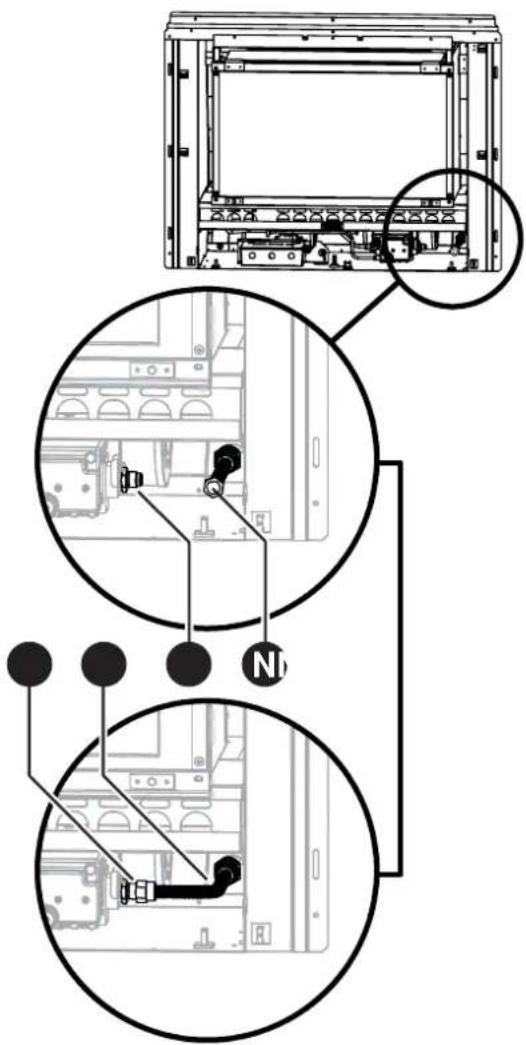
text_image
Technical diagram showing internal components of a server rack with labeled parts and connection pointsHEATER ENGINE INSTALLATION - CONSOLE
FREESTANDING CONSOLE INSTALLATION OVERVIEW

Read this manual thoroughly and gain a full understanding of the requirements before undertaking installation.
Ensure gas supply to heater is turned off for the first stages of this instruction.
Step 1. Prepare Site - p.39
Step 6. Fit Heater Engine To Pillar Assembly - p.40
Step 2. Unpack Heater Engine & Console Kit - p.39
Step 7. Connect Electrical Supply - p.41
Step 3. Assemble & Secure Pillar Assembly - p.39
Step 8. Connecting Gas - p.41
Step 4. Attach Spigot Adaptor & Panels To Heater Engine - p.40
Step 9. Leak Testing - p.41
Step 5. Prepare Gas Supply - p.40
Step 10. Completing Heater Installation - p.41
FREESTANDING CONSOLE INSTALLATION - DETAIL
Step 1. Prepare Site

Ensure the intended installation area has been prepared in accordance with dimensions as stipulated in “GAS SUPPLY” on page 30 and “ELECTRICAL SUPPLY” on page 31.
Ensure there are no wall studs, noggins, ceiling joists, wiring or other obstruction within the wall and or ceiling cavity where the flue is proposed to penetrate.
Step 2. Unpack Heater Engine & Console Kit
The heater engine and the console kit are supplied in separate cartons, check to ensure you have all contents as listed on "BEFORE YOU START" on page 4 at the start of this manual before proceeding.
For heater engine remove carton by removing the straps and carefully lifting the carton off the appliance. Remove all packaging materials and check all components for damage. If ANY damage is evident DO NOT install or operate this appliance. Contact your supplier for advice.

Retain the card board carton for use in the "Attach Spigot Adaptor & Panels To Heater Engine" on page 40.
Before installing the heater, check it is labelled for the correct gas type, (refer to the gas type label on the top body panel of the heater engine). Refer to the local gas authority for confirmation of gas type if you are in doubt.
Step 3. Assemble & Secure Pillar Assembly
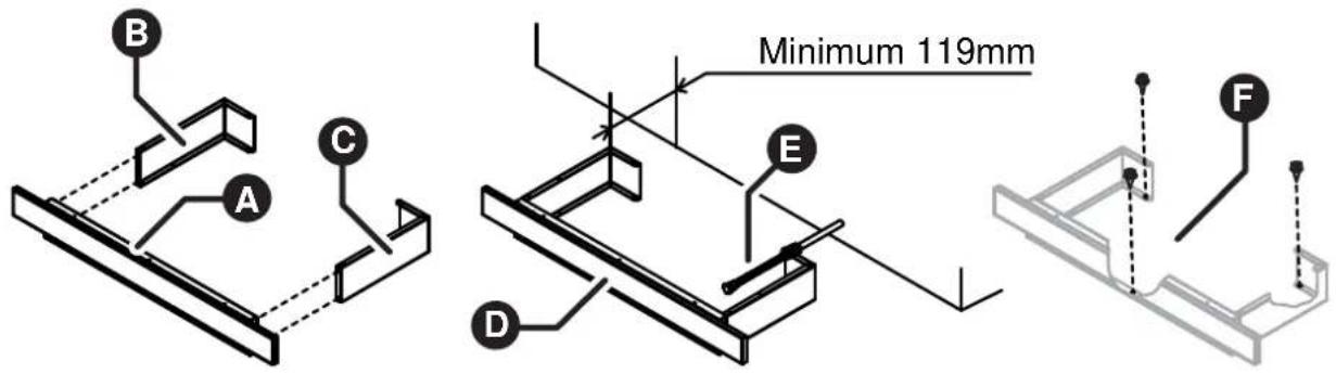
text_image
B A C Minimum 119mm E D FAssemble the pillar assembly A, B and C using the 4 - 8g x 10mm self tapping screws supplied creating base assembly D.

A panel from the cardboard packing carton placed on the floor underneath the heater engine and console components will help prevent possible damage to flooring during assembly.
Confirm the correct gas supply position E and locate the base assembly D in the selected installation position and fasten to the floor using appropriate fasteners (not supplied) through the three holes in the base plate F
HEATER ENGINE INSTALLATION - CONSOLE
Step 4. Attach Spigot Adaptor & Panels To Heater Engine
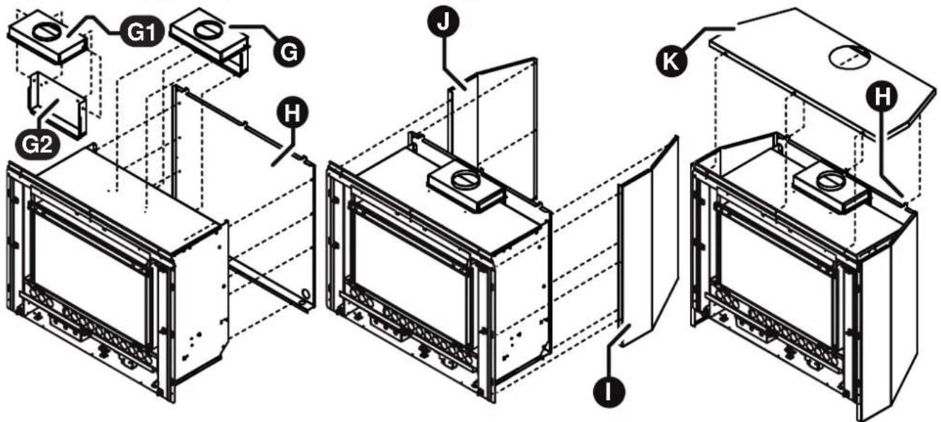
text_image
Technical diagram of a microwave oven assembly with labeled components (G1, G2, H, J, K, I)Assemble the spigot adaptor halves G1 and G2 cure together with 4 x screws (supplied).
Drill 4 x ∅ 3.2mm holes in the pre pressed location dimples on the top and back of the heater engine, then fit the flue spigot adaptor G the heater engine top and rear panels using 4 - 8g x 10mm self tapping screws (supplied).
Fit the rear panel Hsing 9 - 8g x 10mm self tapping screws (supplied).

Before attempting to fit the side panels it is necessary to elevate the heater engine 100mm off the ground.
Fit side Panels ①nd to J eater body at the front and the rear panel using 12 - 8g x 10mm self tapping screws (supplied).
Carefully align top panel K over tabs of the rear panel H, fasten to the heater at the front using 3 - M5 x 12mm screws (supplied) and at the rear using 3 - 8g x 10mm self tapping screws (supplied).
Step 5. Prepare Gas Supply
Remove the threaded brass plug from the S/S flexi pipe consumer gas supply pipe.
Step 6. Fit Heater Engine To Pillar Assembly

The following installation step requires a two man lift. Seek assistance before proceeding further.
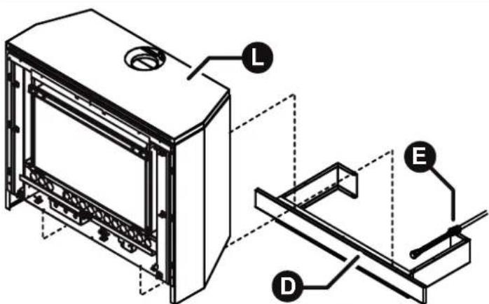
text_image
Technical diagram of a device with labeled components L, E, and D, showing internal structure and assembly lines.Carefully lift the heater engine assembly Ⓛ onto the plinth assembly Ⓓ ensuring that the gas supply pipe and fittings Ⓔ feed into the rear access hole.
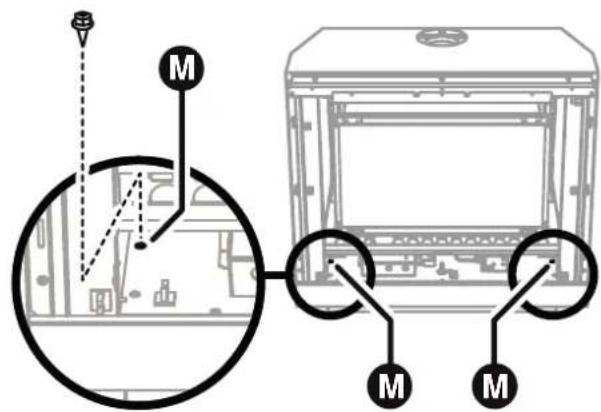
text_image
Technical diagram showing a mechanical assembly with labeled components and connection points, including a circular component and a 3D printing machine.
Take care that the electrical cord does not bunch up or get pinched behind the heater engine.
Align the heater securing holes over the M5 root nuts, then secure using the 4 - M5 x 12mm screws supplied. Note that two screws are located midway into the appliance on the lower left and right edges, refer to detail M above.
HEATER ENGINE INSTALLATION - CONSOLE
Step 7. Connect Electrical Supply
Plug in 3 pin connector, if a general purpose outlet (power point) is used.
Step 8. Connecting Gas
Firmly grasp the S/S flexi pipe E and bend at 90° approximately mid way to line up with the gas control valve inlet N then attach pipe to gas control valve and tighten.
Step 9. Leak Testing
Turn gas back ON and leak test appliance connection.

Use a soapy solution to test all gas connections. If a leak is present bubbles will form at the leak point. When finished remove any residue with a rag. Prevent any soapy solution from coming in contact with electrical components.
Step 10. Completing Heater Installation
Go to "COMPLETING HEATER INSTALLATION" on page 45.
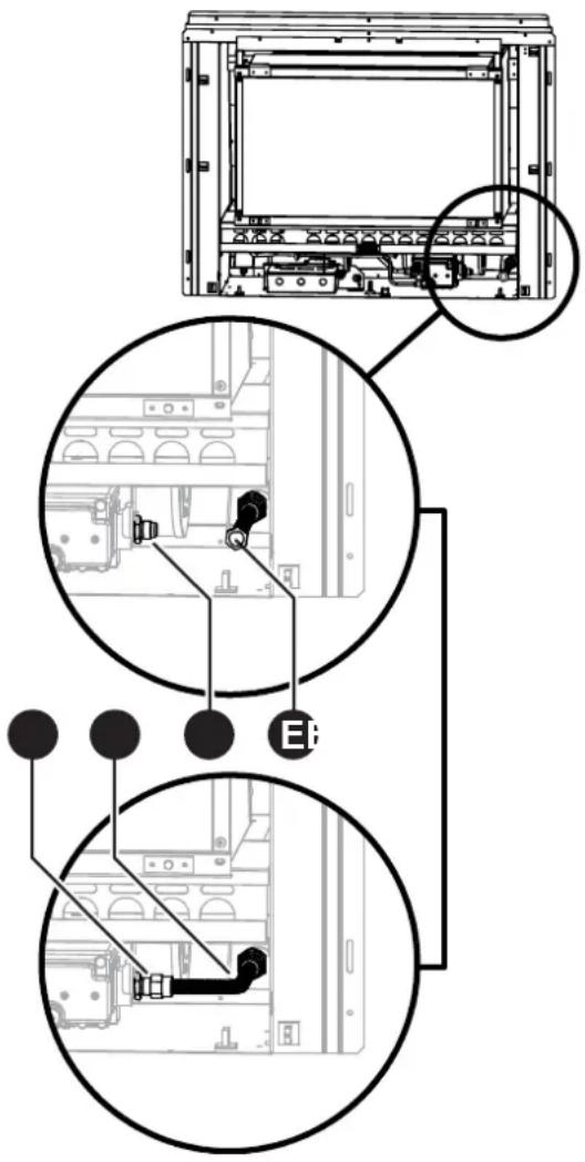
text_image
Technical diagram showing internal components of a server rack with labeled parts and annotationsHEATER ENGINE INSTALLATION - PLINTH
FREESTANDING PLINTH INSTALLATION OVERVIEW

Read this manual thoroughly and gain a full understanding of the requirements before undertaking installation.
Ensure gas supply to heater is turned off for the first stages of this instruction.
Step 1. Prepare Site - p.42
Step 6. Fit Heater Engine To Plinth Assembly - p.43
Step 2. Unpack Heater Engine & Console Kit - p.42
Step 7. Connect Electrical Supply - p.44
Step 3. Assemble & Secure Plinth Assembly - p.42
Step 8. Connecting Gas - p.44
Step 4. Attach Spigot Adaptor & Panels To Heater Engine - p.43
Step 9. Leak Testing - p.44
Step 5. Prepare Gas Supply - p.43
Step 10. Completing Heater Installation - p.44
FREESTANDING PLINTH INSTALLATION - DETAIL
Step 1. Prepare Site

Ensure the intended installation area has been prepared in accordance with dimensions as stipulated in "GAS SUPPLY" on page 30 and "ELECTRICAL SUPPLY" on page 31.
Ensure there are no wall studs, noggins, ceiling joists, wiring or other obstruction within the wall and or ceiling cavity where the flue is proposed to penetrate.
Step 2. Unpack Heater Engine & Console Kit
The heater engine and the console kit are supplied in separate cartons, check to ensure you have all contents as listed on "BEFORE YOU START" on page 4 at the start of this manual before proceeding.
For heater engine remove carton by removing the straps and carefully lifting the carton off the appliance. Remove all packaging materials and check all components for damage. If ANY damage is evident DO NOT install or operate this appliance. Contact your supplier for advice.

Retain the card board carton for use in the "Attach Spigot Adaptor & Panels To Heater Engine" on page 40.
Before installing the heater, check it is labelled for the correct gas type, (refer to the gas type label on the top body panel of the heater engine). Refer to the local gas authority for confirmation of gas type if you are in doubt.
Step 3. Assemble & Secure Plinth Assembly
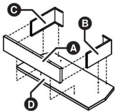
text_image
Technical diagram of a mechanical assembly with labeled components A, B, C, and D
text_image
Minimum 119mm F E GAssemble the pillar assembly AaB supplied creating base assembly E
to t© base panel
D using the 10 - 8g x 10mm self taping screws

A panel from the cardboard packing carton placed on the floor underneath the heater engine and console components will help prevent possible damage to flooring during assembly.
Confirm the correct gas supply position F and locate the base assembly E in the selected installation position and fasten to the floor using appropriate fasteners (not supplied) through the three holes in the base plate G
HEATER ENGINE INSTALLATION - PLINTH
Step 4. Attach Spigot Adaptor & Panels To Heater Engine
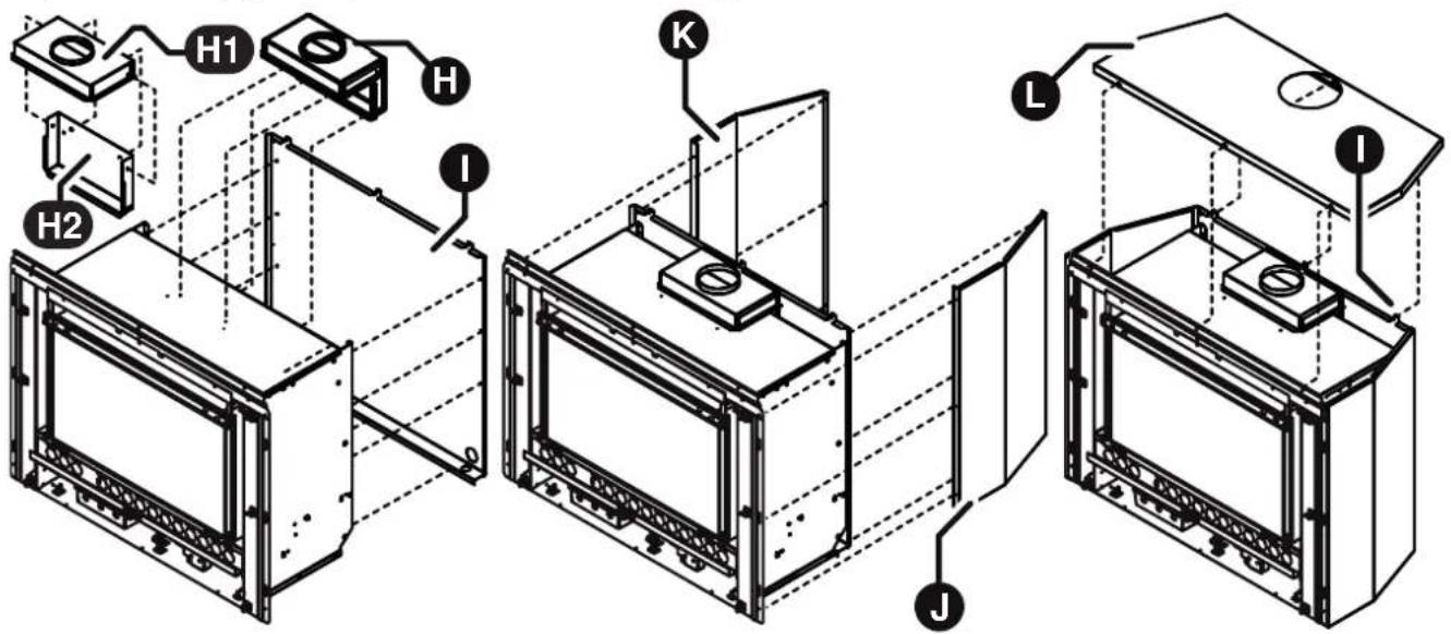
text_image
Technical diagram of a multi-stage appliance assembly with labeled components H1, H2, K, L, and IAssemble the the spigot adaptor halves H1 and H2 cure together with 4 x screws (supplied).
Drill 4 x ∅ 3.2mm holes in the pre pressed location dimples on the top and back of the heater engine, then fit the flue spigot adaptor Ⓗ the heater engine top and rear panels using 4 - 8g x 10mm self tapping screws (supplied).
Fit the rear panel using 9 - 8g x 10mm self tapping screws (supplied).
Fit side Panels 🟢 and toKeater body at the front and the rear panel using 12 - 8g x 10mm self tapping screws (supplied).
Carefully align top panel ⬆ over tabs of the rear panel ⬇, fasten to the heater at the front using 3 - M5 x 12mm screws (supplied) and at the rear using 3 - 8g x 10mm self tapping screws (supplied).
Step 5. Prepare Gas Supply
Remove the threaded brass plug from the S/S flexi pipe consumer gas supply pipe.
Step 6. Fit Heater Engine To Plinth Assembly

The following installation step requires a two man lift. Seek assistance before proceeding further.
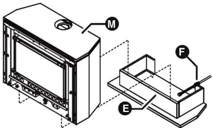
text_image
Technical diagram of a device with labeled components M, F, and E, showing internal structure and assembly.Carefully lift the heater engine assembly Ⓜ onto the plinth assembly Ⓔ ensuring that the gas supply pipe and fittings Ⓕ feed into the rear access hole.
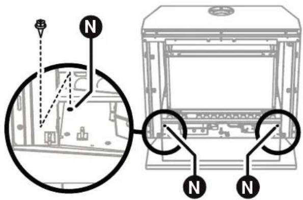
text_image
Technical diagram showing a mechanical assembly with labeled components and directional arrows, including a magnified circular detail view.
Take care that the electrical cord does not bunch up or get pinched behind the heater engine.
Align the heater securing holes over the M5 root nuts, then secure using the 4 - M5 x 12mm screws supplied. Note that two screws are located midway into the appliance on the lower left and right edges, refer to detail N above.
HEATER ENGINE INSTALLATION - PLINTH
Step 7. Connect Electrical Supply
Plug in 3 pin connector, if a general purpose outlet (power point) is used.
Step 8. Connecting Gas
Firmly grasp the S/S flexi pipe F and bend at 90° approximately mid way to line up with the gas control valve inlet ●en attach pipe to gas control valve and tighten.
Step 9. Leak Testing
Turn gas back ON and leak test appliance connection.

Use a soapy solution to test all gas connections. If a leak is present bubbles will form at the leak point, when finished remove any residue with a rag. Prevent any soapy solution from coming in contact with electrical components.
Step 10. Completing Heater Installation
Go to "COMPLETING HEATER INSTALLATION" on page 45.
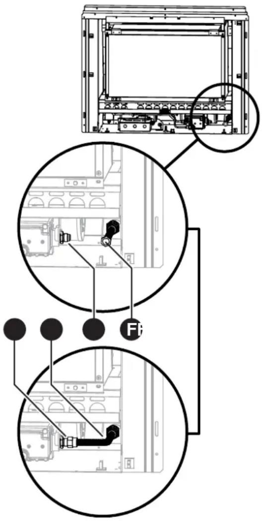
text_image
Technical diagram showing internal components of a server rack with labeled parts and connection pointsCOMPLETING HEATER INSTALLATION
PREPARING FOR COMMISSIONING
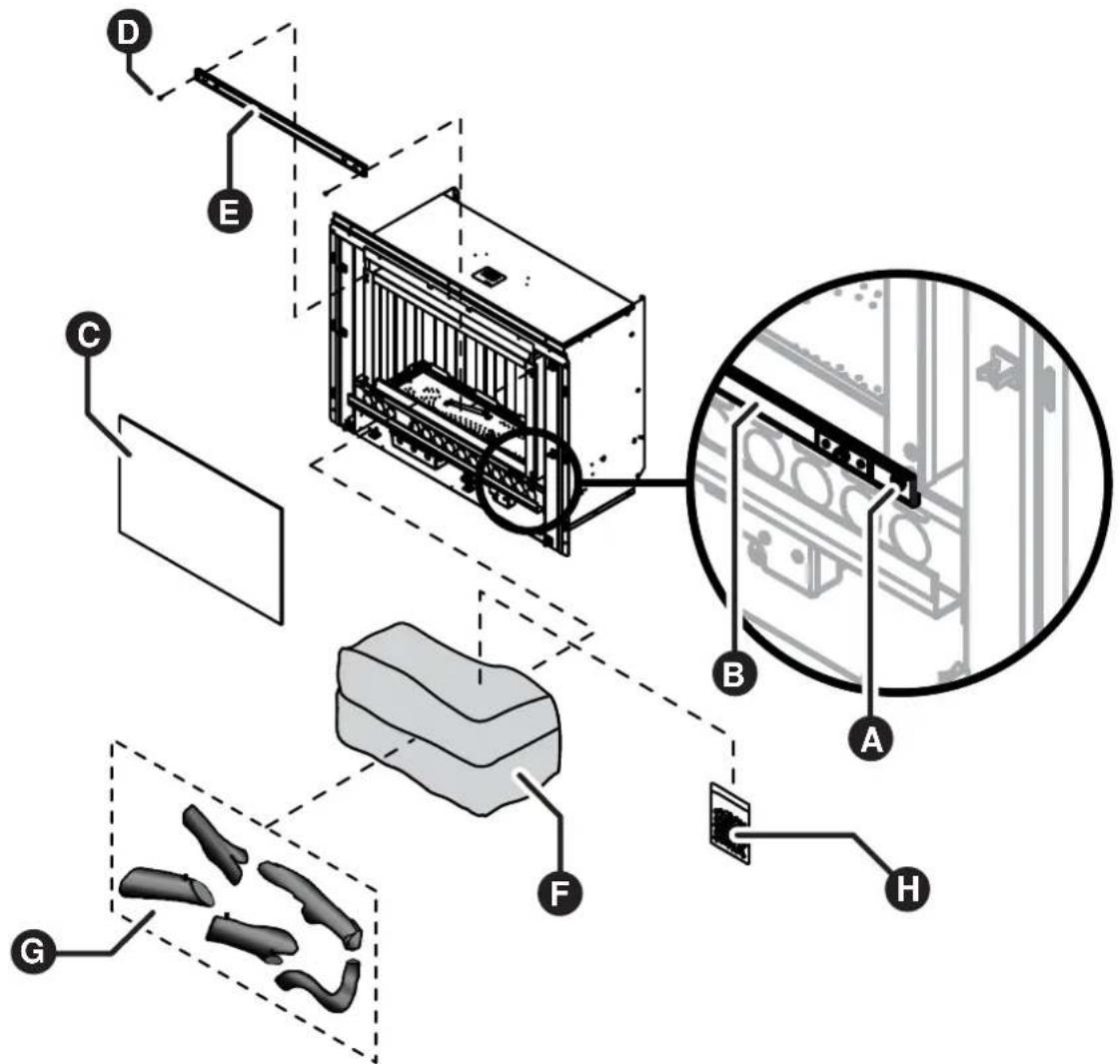
text_image
Technical diagram of a server rack system with labeled components including chassis, panel, and accessoriesStep 1. Removing the Burner Box Glass
Loosen but do not remove the two retaining screws A for the bottom burner box glass clamp B. While supporting the burner box glass panel in place, completely unscrew and remove the two retaining screws D and the top burner box glass clamp E. Then lift burner box glass panel C away and place it safely aside where it can not get damaged.
Step 2. Unpacking Log Set & Granules Satchel
There are two items shipped inside the burner box of the heater engine, these are the log set Ⓖ and the burner granules Ⓗ These items are now accessible for removal.

The satchel containing the burner granules Ⓗ is taped to the outside of the foam packing that contains the log set. Ensure that you locate and remove the satchel before discarding the packaging material.
Carefully unpack the five logs G from the packaging material F and inspect each log for damage, temporarily return logs to the packaging F or safe keeping. After inspection place the logs and the burner granules satchel H safely aside where they can not get damaged. If ANY damage is evident on the logs DO NOT continue with installation and contact your supplier for advice.
COMPLETING HEATER INSTALLATION
Step 3. Installing the Log Set and Burner Granules

For clarity the drawings are displayed without showing the entire heater.
DO NOT remove the burner from heater engine to install the log set.
Use extreme care when handling the Log Set components, they are made from a very fragile high temperature material and will damage if handled roughly. Only remove the components from their packaging as required.
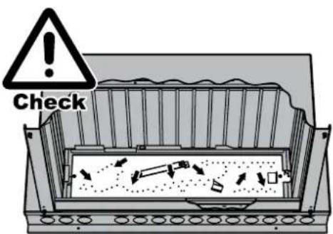
text_image
Check⚠️ Check to ensure that the ports of the burner are clean and clear of any particles and all packaging material. The log set MUST BE installed in the precise order as stated.
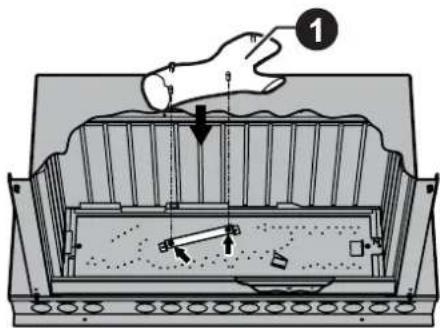
text_image
Diagram illustrating a mechanical or electrical process with labeled components and directional arrows, including a hand pressing down on a component.Log 1nick 'Y' shaped log with two locating holes and pins. Line up the holes with the pins of the bracket fixed to the centre of the burner. When correctly positioned the log rests on this bracket.
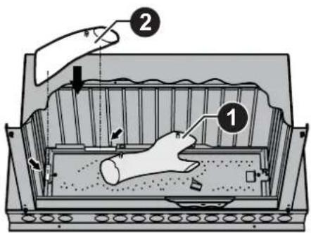
text_image
Diagram illustrating a hand operating a device with labeled parts 1 and 2, showing internal components and directional arrows.Log 2he short straight log with a single locating pin. Place the log onto the sheet metal tabs at the left and rear of the burner box. When correctly positioned this log will be touching the left and rear burner box walls.
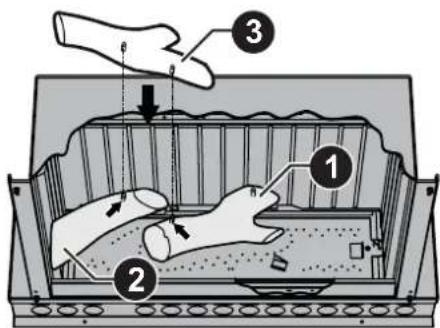
text_image
Diagram illustrating a hand operating a device with labeled parts and directional arrows indicating movement or process.Log ③hinner 'Y' shaped log with two locating holes. Line up the holes with the pins of logs ①and . ② When correctly positioned the log rests on both logs ① and ②.
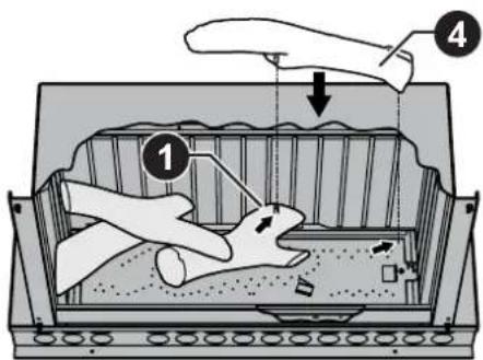
text_image
Diagram illustrating a mechanical or fluid system with labeled components and directional arrows, likely from an engineering or physics context.Log 4ong log with a single locating hole. Line up the hole with the pin of log 1 When correctly positioned this log will be touching log 1 the rear burner box wall and the burner.
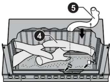
text_image
Diagram illustrating a hand operating a container with labeled parts and directional arrows indicating movement or process.Log 5 owed log with a single locating hole. Line up the hole with the pin bracket to the right of the burner and locate the front of log onto the stop bracket. When correctly positioned this log will be touching both brackets, log 4 and the right burner box wall.
COMPLETING HEATER INSTALLATION
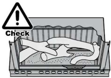
text_image
Check⚠️ Confirm the correct location of all the logs before proceeding with the placement of the granular burner medium, ensuring that all the logs are firmly seated in their correct positions and that the ports of the main burner are clean and clear of any debris that may have been shed during the log installation.
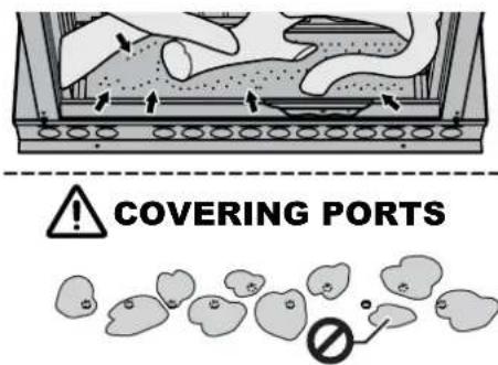
text_image
COVERING PORTSFor best flame effect carefully place the granular burner medium over and around the front burner ports. It is desirable that the gas jet is diffused by the granules, this will reduce any 'candling' effect of the flame enhancing the realistic log burning look of the heater.
⚠ DO NOT force any granular material into the burner ports or completely block any of the burner ports.
Step 4. Replacing the Burner Box Glass
Replace burner box glass panel assembly in reverse sequence as instructed in Step 2. page 45.
Step 5. Unpack the Fascia Assembly & Inner Frame
The Fascia Assembly and the Inner Frame are supplied in a separate carton, check to ensure you have all the contents as listed on "CARTON CONTENTS / ITEM CHECKLIST" on page 4 at the start of this manual before proceeding. Remove all packaging materials and check all components for damage. If ANY damage is evident DO NOT install or operate this appliance. Contact your supplier for advice.

When placing the standard facia assembly down ensure it is placed on its lower edge or flat. If it is placed on its left or right edge the glass may slide out of the stand off posts. If this should occur ensure that the silicon rubber mounts are not dislodged when sliding the glass back into position.
Step 6. Fitting the Inner Frame

text_image
Technical diagram showing labeled components of a device with annotations A, B, C, D, E and internal circular features.The inner frame A is packed with the Fascia and can now be fitted to the heater engine. The inner frame is held in position by return tabs B on the top edge and by magnets Cn the bottom edge.
Fit the inner frame A to the heater engine by locating the over-folded edge B over the two return tabs C then gently swing down the bottom edge D into the magnets . E
COMPLETING HEATER INSTALLATION
Step 7. Connect the Push Button Control Panel
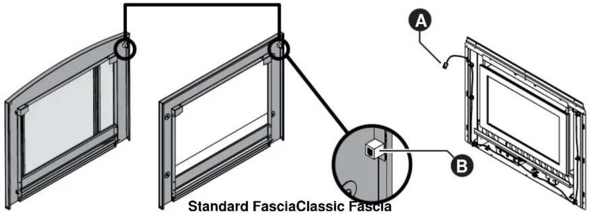
text_image
Standard FasciaClassic Fascia A BCarefully pick up fascia assembly, taking care not to tilt the standard model fascia on it's edge as the glass may slide out from the stand off posts.
Position the fascia close to the heater engine and connect the RJ45 plug A to the socket B located on the back of fascia on the top left hand corner, (this connects the push button control panel via a communications cable to the heater engine's control box).
Step 8. Switch On the Electricity Supply
Switch on the electricity supply, the appliance is now ready for commissioning.

240 VOLTS, RISK OF ELECTRICAL SHOCK!
When performing the commissioning, the appliance electrical power will need to be connected. Exercise CAUTION as there is potential for electric shock from the exposed wiring and circuitry. DO NOT leave the appliance unattended when power is connected and the panels are removed.
Installation and commissioning must be carried out by an Authorised person.
Wiring inside this appliance may be at 240V potential.
DO NOT test for gas escapes with an open flame.
COMPLETING HEATER INSTALLATION
COMMISSIONING THE APPLIANCE

The gas type codes and gas pressures for this appliance MUST BE checked and set in accordance with these instructions when the appliance is installed, OR after the replacement of any component or reassembly after service.
Step 9. To check and set burner pressures:
- Refer to the data plate located on the front left panel of the heater engine for correct gas pressure settings.
- Using a suitable screw driver loosen the captive Appliance Test Point Pressure screw (ATPP) and fit the manometer, (an electronic manometer is recommended). Refer images for ATPP location.
-
Remove the dust cap from the regulator adjusting nut and screw.
-
High Pressure Setting:
Turn the appliance 'ON' and set the heater to the highest setting, see "TO TURN YOUR HEATER ON" on page 12. Using an appropriate screw driver hold the low pressure adjusting screw ® stationary while adjusting the high pressure setting, nut Ⓐ with a 10 mm spanner. Turning the nut clockwise will increase the outlet pressure whilst turning the nut anti-clockwise will decrease the outlet pressure.
- Low Pressure Setting:
Disconnect the power to the Gas Control Valve (GCV) by separating the connector © for the power supply (yellow wires). The GCV will automatically default to 'Low Pressure' operation. Using a 10 mm spanner hold the high pressure adjusting nut Ⓐ stationary while adjusting the low pressure setting, screw Ⓑ with an appropriate screw driver. Turning the screw clockwise will increase the outlet pressure whilst turning the screw anti-clockwise will decrease the outlet pressure.
- Replace the dust cap after pressure adjustments.

To ensure the correct operation of the GCV it is necessary that the dust cap @s returned to its original location.
- Reconnect the power to the GCV by rejoining the connector Ⓔ (yellow wires).
- After confirming the correct pressures, turn the appliance 'OFF', remove manometer and tighten the ATPP sealing screw and leak test.
- Turn the appliance 'ON' and 'OFF' a few times to confirm correct ignition and operation.
- During the initial burn in period, some smoke and smell may be emitted. The appliance should be run on the high setting in a well ventilated room until these dissipate.
- Check the flame pattern, see "ABNORMAL FLAME PATTERN" on page 51.
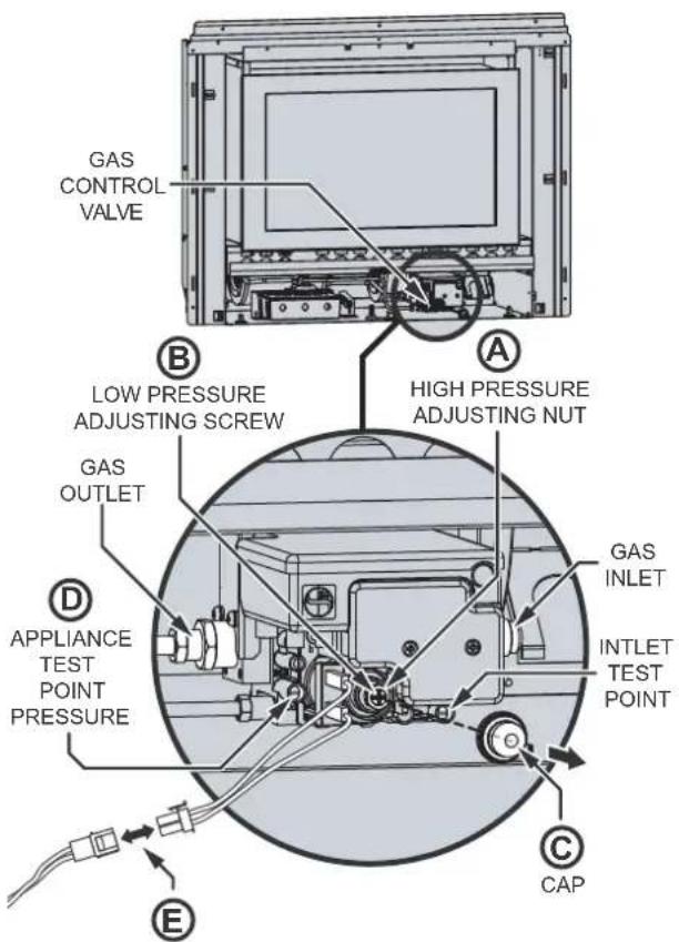
text_image
GAS CONTROL VALVE B LOW PRESSURE ADJUSTING SCREW A HIGH PRESSURE ADJUSTING NUT GAS OUTLET D APPLIANCE TEST POINT PRESSURE GAS INLET INTLET TEST POINT E C CAPGAS CONTRL VALVE
POWER CONNECTOR
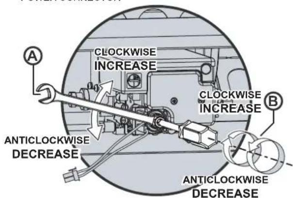
text_image
CLOCKWISE INCREASE ANTICLOCKWISE DECREASE CLOCKWISE INCREASE ANTICLOCKWISE DECREASE
text_image
D APPLIANCE TEST POINT PRESSURE E GAS CONTROL VALVE POWER CONNECTOR C CAPCOMPLETING HEATER INSTALLATION
ATTACHING FASCIA ASSEMBLY
Step 12. Attach the Fascia to the Heater Engine

text_image
Standard Fascia Rear View of Fascias for reference Classic FasciaLocate and remove the two 8g - 10mm fascia assembly securing screws A re-positioned in the fascia mounting tabs B on the heater engine body.

These screws have been pre-inserted by the manufacturer to ensure correct threading of the fascia securing tabs.
Carefully pick up fascia assembly, taking care not to tilt the standard model fascia on it's edge as the glass may slide out from the stand off posts.
Position the top fold D over the fascia assembly mounting panel E and gently push the lower edge of the fascia assembly until it is flush at the edges.

Ensure you DO NOT place excessive tension on or pinch the communication cable @when manoeuvring the fascia into position.
Fit and tighten the two fascia retaining screws A through both the fascia F and the fascia mounting tabs B on the heater engine body.

The glass dress guard (standard model) and the mesh dress guard (classic model) fitted to this appliance reduces the risk of fire and injury and no part of it should be permanently removed. For protection of young children or the infirm a secondary guard is required.

If the heater is not operating correctly refer to the “TROUBLE SHOOTING CHECKLIST” on page 23 before contacting Rinnai.
It is the responsibility of the installer to check that under normal operating conditions of the appliance, all flue gases are exhausted to the outside atmosphere and that there is no spillage of combustion gases into the room. Please refer to AS 5601.
During the initial burning in period of approximately 2 hours, some smoke and smell may be experienced. During this period the heater should be operated on High and the space being heated should be well ventilated. It may take up to 20 minutes of operation for the logs to achieve their full flame pattern and glow.
Burner aerations are factory set and can not be adjusted. If you are unable to get the unit to operate correctly refer to "TROUBLE SHOOTING CHECKLIST" on page 23 before contacting Rinnai.
COMPLETING HEATER INSTALLATION
ATTACHING DRESS GUARD TO CLASSIC FASCIA ASSEMBLY
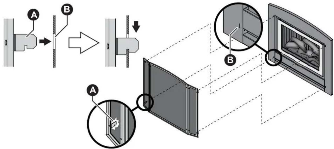
flowchart
graph TD
    A["Component A"] --> B["Component B"]
    B --> C["Final Display"]
    subgraph Component A
        D["Component D"]
        E["Component E"]
    end
    subgraph Component B
        F["Component F"]
        G["Component G"]
    end
The mesh dress guard of the classic model fascia is held in place by four slotted tabs (two on each side) A which lock into four slots B on the front of the fascia.
ABNORMAL FLAME PATTERN
Each Rinnai Flame Fire heater has a distinct flame pattern. The flame should look the same every time you start your heater, after an initial warm up period of approximately 15 minutes.
Abnormal flame performance and/or pattern can indicate a problem with your heater, such as blocked gas injectors, incorrectly installed / inadequate flue system or the artificial logs/burn media may have shifted from when the heater was first installed.
There are some warning signs that could indicate a problem. If any of the signs below occur, please contact Rinnai.
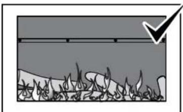
natural_image
Diagram showing a grassy field with a black arrow pointing to a horizontal line and a small object, no text or symbols present.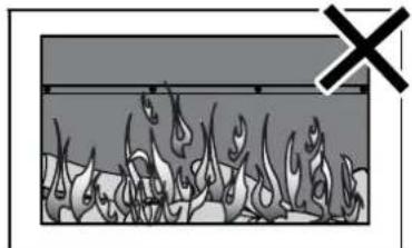
natural_image
Diagram showing a container with multiple flame-like shapes and a cross symbol (no text or labels)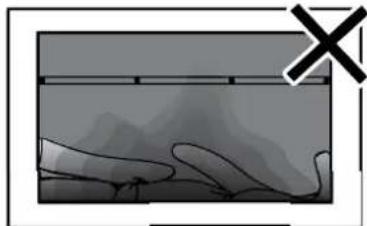
natural_image
Diagram showing a hand holding a tool with a cross symbol, no readable text or labels presentNORMAL FLAME PATTERN ABNORMAL FLAME PATTERN SOOT BUILD UP
Key signs of abnormal flame performance:
- Appliance turns 'OFF' soon after start up and does not relight.
- Flame appears overly orange-yellow.
- Flame appears either very short or very long.
- Flame only burns part way across the burner.
- Severe soot building up on the inside of the glass and logs.
- Continuous unusual smell from the appliance.
- Continued difficulty or delay in establishing a flame.

Be advised that appliances incorporating a live fuel effect, and designed to operate with luminous flames, may exhibit slight carbon deposition, this is normal operation.
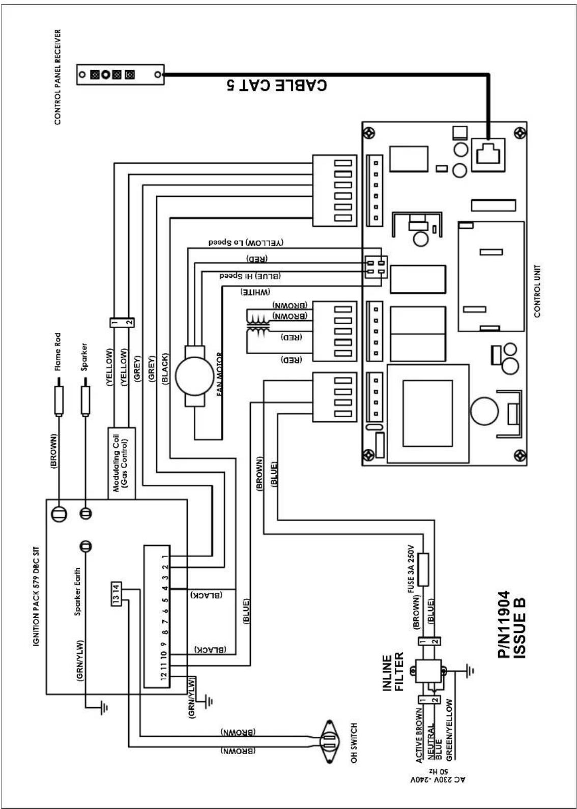
flowchart
graph TD
    A["IGNITION PACK 579 DBC SIT"] --> B["(GRN/YLW)"]
    A --> C["Sparker Earth"]
    B --> D["(BRDN)"]
    C --> E["(BRDN/YLW)"]
    D --> F["Modulating Coil (Gas Control)"]
    E --> G["Modulating Coil (Gas Control)"]
    F --> H["(YELLOW)"]
    F --> I["(YELLOW)"]
    F --> J["(GREY)"]
    G --> K["(GREEN)"]
    G --> L["(GREY)"]
    H --> M["FAN MOTOR"]
    I --> M
    J --> M
    K --> N["(RED)"]
    K --> O["(RED)"]
    K --> P["(BROWN)"]
    K --> Q["(BROWN)"]
    K --> R["(BROWN)"]
    K --> S["(BROWN)"]
    L --> T["(BLUE)"]
    L --> U["(BLUE)"]
    M --> V["(BLUE)"]
    N --> W["(BLUE)"]
    O --> X["(BLUE)"]
    P --> Y["(BLUE)"]
    Q --> Z["(BLUE)"]
    R --> AA["(BLUE)"]
    S --> AB["(BLUE)"]
    T --> AC["(BLUE)"]
    U --> AD["(BLUE)"]
    V --> AE["(BLUE)"]
    W --> AF["(BLUE)"]
    X --> AG["(BLUE)"]
    Y --> AH["(BLUE)"]
    Z --> AI["(BLUE)"]
    AD --> AJ["(BLUE)"]
    AE --> AK["(BLUE)"]
    AF --> AL["(BLUE)"]
    AG --> AM["(BLUE)"]
    AH --> AN["(BLUE)"]
    AI --> AO["(BLUE)"]
    AJ --> AP["(BLUE)"]
    AK --> AQ["(BLUE)"]
    AL --> AR["(BLUE)"]
    AM --> AS["(BLUE)"]
    AN --> AT["(BLUE)"]
    AO --> AU["(BLUE)"]
    AP --> AV["(BLUE)"]
    AQ --> AW["(BLUE)"]
    AR --> AX["(BLUE)"]
    AS --> AY["(BLUE)"]
    AT --> AZ["(BLUE)"]
    AU --> BA["(BLUE)"]
    AV --> BB["(BLUE)"]
    AW --> BC["(BLUE)"]
    AX --> BD["(BLUE)"]
    AY --> BE["(BLUE)"]
    AZ --> BF["(BLUE)"]
    BA --> BG["(BLUE)"]
    BB --> BH["(BLUE)"]
    AC --> BI["(BLUE)"]
    AD --> BJ["(BLUE)"]
    AE --> BK["(BLUE)"]
    AF --> BL["(BLUE)"]
    AG --> BM["(BLUE)"]
    AH --> BN["(BLUE)"]
    AI --> BO["(BLUE)"]
    AJ --> BP["(BLUE)"]
    AK --> BQ["(BLUE)"]
    AL --> BR["(BLUE)"]
    AM --> BS["(BLUE)"]
    AN --> BT["(BLUE)"]
    AO --> BU["(BLUE)"]
    AP --> BV["(BLUE)"]
    AQ --> BW["(BLUE)"]
    AS --> BX["(BLUE)"]
    AT --> BY["(BLUE)"]
    AU --> BZ["(BLUE)"]
    AV --> CA["(BLUE)"]
    AW --> CB["(BLUE)"]
    AX --> CC["(BLUE)"]
    AY --> CD["(BLUE)"]
    AZ --> CE["(BLUE)"]
    BA --> CF["(BLUE)"]
    BB --> CG["(BLUE)"]
    AC --> CH["(BLUE)"]
    AD --> CI["(BLUE)"]
    AE --> CJ["(BLUE)"]
    AF --> CK["(BLUE)"]
    AG --> CL["(BLUE)"]
    AH --> CD
    AI --> CE
    AJ --> CF
    AK --> CG
    AL --> BH
    AM --> BI
    AN --> BJ
    AO --> BK
    AP --> BL
    AQ --> BM
    AS --> BN
    AT --> CO
    AU --> CP
    AV --> CR
    AW --> CS
    AX --> CT
    AY --> CU
    AC --> CU
    AD --> CU
    AE --> CU
    AF --> CU
    AG --> CU
    AH --> CU
    AI --> CU
    AJ --> CU
    AK --> CU
    AL --> CU
    AM --> CU
    AN --> CU
    AO --> CU
    AP --> CU
    AU --> CU
    AV --> CU
    AH --> CU
    AI --> CU
    AJ --> CU
    AK --> CU
    AL --> CU
    AM --> CU
    AN --> CU
    AO --> CU
    AP --> CU
    AU --> CU
    AV --> CU
    AH --> CU
    AI --> CU
    AJ --> CU
    AK --> CU
    AL --> CU
    AM --> CU
    AN --> CU
    AO --> CU
    AU --> CU
    AV --> CU
    AH --> CU
    AI --> CU
    AJ --> CU
    AK --> CU
    AL --> CU
    AM --> CU
    AN --> CU
    AO --> CU
    AU --> CU
    AV --> CU
    AH --> CU
    AI --> CU
    AJ --> CU
    AK --> CU
    AL --> CU
    AM --> CU
    AN --> CU
    AU --> CU
    AV --> CU
    AH --> CU
    AI --> CU
    AJ --> CU
    AK --> CU
CHECKLIST
INSTALLATION AND COMMISSIONING CHECKLIST
- Complete the Installation Check List and the Installer details below.
- Instruct customer on the Sapphire operation.
- Ensure the customer understands the content of this manual.

Advise the customer that during the initial burning period of approximately 2 hours, some smoke and odour may be experienced. During this period the heater should be operated on 'High' and the space being heated should be well ventilated. It may take up to 20 minutes of operation for the logs to achieve their full flame pattern and glow.

The glass dress guard (standard model) and the mesh dress guard (classic model) fitted to this appliance reduces the risk of fire and injury and no part of it should be permanently removed.
- For protection of young children or the infirm a secondary guard is required.
- Ensure this Operation and Installation manual is left with the customer.

Ensure the Customer understands that:
No part of this appliance should be permanently removed.
Paper or other material must not be burnt in this appliance.
Young children and the infirm should be supervised at all times.
Checklist To Be Completed By Certified Gas Installer
NO / YES
- Is the appliance positioned in a suitable location (clearances, combustible clearances, mantels and surrounds etc)?
- Was a Rinnai approved flue system installed and tested in accordance with the instructions?
- Has the gas pressure checked and set?
- Has the log set / burn media been installed as per instructions?
- Was the appliance tested for correct operation and to ensure no gas leaks?
- Has the customer been instructed on operating procedure and safety requirements?
- Is the end-user fully aware of operating procedure?
- Has the Dress Guard been fitted?
- Has the customer been advised not to remove the dress-guard?
- Has the customer been advised to service the heater every two years?

NOTES
NOTES
Rinnai
Rinnai Australia Pty. Ltd. ABN 74 005 138 769
Head Office
100 Atlantic Drive,
Keysborough VIC 3173
P.O. Box 460
Braeside, VIC 3195
Rinnai has a Service and Spare Parts network with personnel who are fully trained and equipped to give the best service on your Rinnai appliance. If your appliance requires service, please call our National Help Line. Rinnai recommends that this appliance be serviced every 2 years.
Product Sales and Service - National
Phone: 1300 555 545* Fax: 1300 555 565*
Technical Helpline and Spare Parts
National (Mon-Fri 8am - 5.30pm EST)
Phone: 1300 555 545* Fax: 1300 300 141*
*Cost of a local call higher from mobile or public phones.
E-mail: enquiry@rinnai.com.au
For further information visit: www.rinnai.com.au