
DEPH-22DTW - Heating Rinnai - Free user manual and instructions
Find the device manual for free DEPH-22DTW Rinnai in PDF.


| Product Type | Gas Heater |
| Model | DEPH-22DTW |
| Brand | Rinnai |
| Heat Output | 22 kW |
| Dimensions (W x H x D) | 600 x 400 x 200 mm |
| Weight | 15 kg |
| Power Supply | Gas (Natural Gas or LPG) |
| Ignition | Electronic ignition |
| Control | Digital thermostat with remote control option |
| Safety Features | Flame failure device, overheat protection, anti-freeze function |
| Installation Type | Wall-mounted or floor-standing |
| Ventilation | Room-sealed (balanced flue) |
| Energy Efficiency | Class A |
| Noise Level | ≤ 45 dB |
| Suitable Room Size | Up to 150 m² |
| Maintenance | Clean external surfaces with damp cloth; annual service recommended |
| Spare Parts Availability | Available from Rinnai authorized dealers |
| Repairability Index | 8.5/10 |
| Warranty | 5 years on heat exchanger, 2 years on parts |
| Certifications | CE, UKCA |
Frequently Asked Questions - DEPH-22DTW Rinnai
User questions about DEPH-22DTW Rinnai
0 question about this device. Answer the ones you know or ask your own.
Ask a new question about this device
Download the instructions for your Heating in PDF format for free! Find your manual DEPH-22DTW - Rinnai and take your electronic device back in hand. On this page are published all the documents necessary for the use of your device. DEPH-22DTW by Rinnai.
USER MANUAL DEPH-22DTW Rinnai
natural_image
Line drawing of a flat-screen electric heater with cooling fans and connected cables (no text or symbols)For safe, reliable operation and optimum performance this appliance must be installed, operated and maintained in accordance with these instructions.
Read these instructions thoroughly before attempting installation and operation.
Keep these instructions handy for future reference.
BEFORE PROCEEDING WITH THE OPERATION OR INSTALLATION OF YOUR NEW HEATER PLEASE READ THIS MANUAL THOROUGHLY AND GAIN A FULL UNDERSTANDING OF THE REQUIREMENTS, FEATURES AND OPERATION OF YOUR NEW APPLIANCE.
WARRANTY, FEATURES & SPECIFICATIONS....5
WARRANTY 5
FEATURES 5
SPECIFICATIONS 5
SAFETY & IMPORTANT POINTS....6
UNPACKING THE APPLIANCE 6
WHAT'S IN THE BOX....6
SAFETY 6
HOW TO OPERATE THE HEATER....7
GENERAL DESIGN LAYOUT....7
CONNECTING THE POWER 8
OPERATION....8
SERVICE AND REPAIR 11
DISPOSAL....11
INSTALLATION....12
GENERAL....12
WALL INSTALLATION....12
FREESTANDING INSTALLATION 14
CONTACT INFORMATION ....16
This page is intentionally blank
WARRANTY
The benefits to the consumer given by this warranty are in addition to all other rights and remedies of the consumer under a law in relation to the goods or services to which the warranty relates.
Our goods come with guarantees that cannot be excluded under the Australian Consumer Law. You are entitled to a replacement or refund for a major failure and for compensation for any other loss or damage. You are also entitled to have the goods repaired or replaced if the goods fail to be of acceptable quality and the failure does not amount to a major failure.
This heater has a 7 year parts warranty from date of purchase. If the product fails within this 7 year period return it to the supplier with proof of purchase for repair or replacement.
Supplier warranty claims for Rinnai products or services must be made by contacting Rinnai Australia. Contact details are on the back of this document.
The following exclusions may cause the warranty to become void and may result in a service charge and costs of parts (if required):
- Accidental damage and acts of God.
- Failure due to abuse or misuse, improper maintenance, failure to maintain or improper storage.
- Failure due to incorrect or unauthorised installations or outdoors use.
- Failure or damage caused by alterations, service or repair work carried out by persons other than Rinnai service persons or service agents.
- Where it is found that there is no fault with the appliance and the issue is related to the installation or is due to the failure of electricity supply.
FEATURES
This heater incorporates the following design features.
DIY Installation:
This heater is suitable for Do It Yourself installation.
Silent Operation:
Electric element operation eliminates fan noise.
Draft Free: Non fan operation also means no drafts.
Delay Off Timer Function:
Equipped with delay off timer, see page 9 for details.
Low Maintenance: No moving parts makes for virtually maintenance free operation.
Tilt Switch:
This heater is fitted with a tilt switch that automatically places the heater into standby mode if the appliance tilts more than 45^ .
'Tamper Resistant' Operation:
Includes a Lock function designed to prevent accidental operation and small children from altering the heater settings.
Operation: The heater uses electricity as the heating medium. It operates on the
‘natural convection’ principle where air from the room is drawn into the ‘air inlet’ louvres at the base of the appliance, is heated inside the appliance and expelled through the ‘air outlet’ louvres at the top of the appliance without the use of fans. A sophisticated thermostatic system keeps the room close to the selected temperature.
SPECIFICATIONS
| Model DEPH-22DTW DEPH-15DTW DEPH-10DTW | ||||
| Rated Power 2200 Watt 1500 Watt 1000 Watt | ||||
| Rated Voltage | 240V ~ 50Hz | |||
| Water Resistance (IP) Rating / Electrical Protection Class | IP24 / Class I | |||
| Dimensions | Height | 400mm | 400mm | 400mm |
| Width | 1060mm | 640mm | 480mm | |
| Depth | 110mm | 110mm | 110mm | |
| Weight | 7.1kg | 4.5kg | 3.5kg | |
| Installation Options | Wall or Freestanding | |||
UNPACKING THE APPLIANCE
If any damage is evident DO NOT INSTALL or OPERATE and contact your supplier for advice.
WHAT'S IN THE BOX
The package should contain:
Heater fitted with flexible cord and plug.
A plastic bag containing the Operating and Installation Instructions, wall mounting screws and mounting brackets.
A box containing four castors, two castor feet and a screwdriver.
SAFETY
It is important the following precautions are followed to minimise the risk of overheating, fire, electric shock and injury.

- The heater is fitted with an Australian flexible cord and 3 pin plug intended for connection to an Australian 10 Amp socket outlet. It is not suitable for connection in other countries or alternative power supplies. Ensure that the voltage and frequency of the power supply correspond to the ratings on the dataplate of the appliance.
- This heater must not be located immediately below or directly in front of a socket-outlet.
- This heater is not intended for use by persons (including children) with reduced physical, sensory or mental capabilities, or lack of experience and knowledge, unless they have been given supervision or instruction concerning use of the appliance by a person responsible for their safety.
- Young children should be supervised to ensure they do not play with the appliance.
- DO NOT allow children or persons with reduced physical, sensory or mental capabilities to sleep directly in front of the heater.
- DO NOT allow children to ‘post articles’ into the louvres of the heater.
- The electrical cord must not come into contact with the heated parts of the heater.
- DO NOT use power boards or double adaptors with this heater.
- DO NOT coil or bundle the electric cord to reduce it's length as overheating of the cord may occur which could result in a fire hazard.
- The flexible cord and plug must not be modified. If the cord or plug are damaged, they must be replaced by Rinnai or a Rinnai appointed service agent.
- DO NOT cover or place articles on or against any parts of this heater, to avoid overheating.
• DO NOT sit on this heater. - If used as a portable heater, do not use in the immediate surroundings of a bath, a shower or a swimming pool.
- If used as a portable heater, unplug and allow to cool before placing in storage.
- If used as a portable heater, do not move whilst it is turned on.
- DO NOT unplug the heater by pulling on the flexible cord.
- DO NOT handle any parts of the heater, including the plug and flexible cord, with wet or damp hands.
- DO NOT immerse the appliance, flexible cord and plug in water or any other liquid.
- DO NOT place containers of any liquid or wax on top of the heater.
- Turn off the appliance and unplug from the power socket outlet when not in use.
- DO NOT use in areas where flammable liquids are stored.
- This appliance is suitable for indoor use only.
- Never dismantle the appliance. Tampering with electrical connections and components is highly dangerous and may cause appliance malfunction.
GENERAL DESIGN LAYOUT
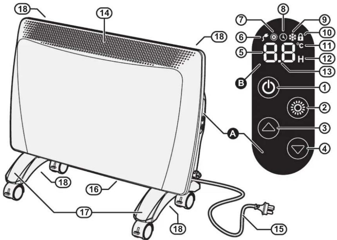
A Control panel console
B Digital LED display
① POWER 'ON' / 'OFF' button
② MODE button, temperature/timer setting
③ 'UP' button
④ 'DOWN' button
⑤ Temperature / Timer display
⑥ Power indicator
⑦ Heater Operation indicator (Red)
⑧ Delay Off Timer Set indicator (Green)
⑨ Constant Frost protection indicator
⑩ Lock indicator
⑪ Degrees celsius indicator (illuminates when the digital display is showing temperature related settings)
⑫ Time indicator (illuminates when digital the display is showing delay timer related settings)
⑬ Tilt warning indicator and 30min interval digit for timer
⑭ Vent, warm air discharge
⑮ 240 Volt power cord & plug
⑯ Air inlets
⑰ Optional castors for floor mounting (see "INSTALLATION" on page 14 for installation options)
⑱ Optional brackets for wall mounting (see "INSTALLATION" on pages 12 & 14 for installation options)

This heater features audible chimes. On start up a set of rising chimes will sound, while on shut down a set of falling chimes will sound, there is also a chime for each button press and if the heater is tilted beyond 45° a continuous tilt warning chime will sound.
7
6
5
11
1
2
3
4
14
CONNECTING THE POWER
Plug the heater into a power outlet and turn the power outlet on. Once power is connected the rising start up chime will sound and the power indicator 6 will illuminate on the Digital LED display to show the heater is now in standby mode.
OPERATION
- Press the POWER button 1 on the control panel console once to start heating operation, a second rising chime will sound. The two digits 5 on the display panel will now show the programmed temperature setting.
The factory temperature setting for the heater is 21^ C. If this is above that of the current room temperature the red operation indicator 7 will illuminate and the heater will begin to heat the room.
- To change the temperature setting press the MODE button 2 once. The °C (temperature) indicator 11 on the display panel will flash.
NOTE
If after 5 seconds no buttons are pressed the °C indicator will stop flashing and the display will revert back to the current operating setting. Simply press the MODE button 2 to re-enter temperature setting operation.
Press the 'Up' 3 or 'Down' 4 buttons to increase or decrease the temperature setting. The available temperature setting range is from 5°C to 30°C.
- To exit the temperature setting operation either press the MODE button 2 twice or wait 5 seconds. The selected temperature will now be set and displayed.
If the selected temperature is above that of the current room temperature the red operation indicator 7 will illuminate and the heater will begin to heat the room.
If the selected temperature is less than that of the current room temperature the red operation indicator 7 will go out and the heater will go into a standby state until the room temperature has fallen below the set temperature, when the heater will then automatically switch on and heat the room.
- To stop heater operation completely press POWER button 1, the shutdown falling chime will sound, the power indicator 6 will remain illuminated to show that the heater has returned to standby mode.
During the initial burning in period or after long periods of non use some light grey smoke or smell may be experienced. This is normal and is caused by dust that may have settled on the heating element. During this period the space being heated should be well ventilated.
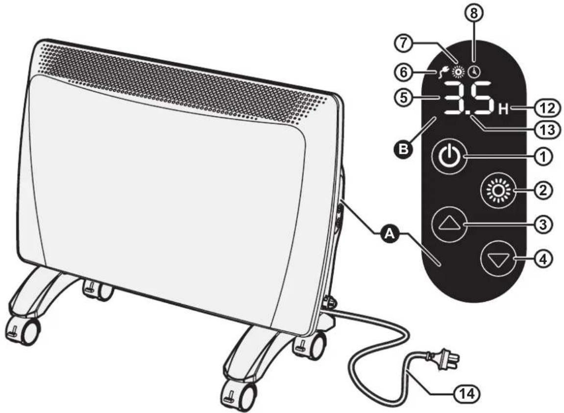
In addition to temperature controlled operation the heater can also be operated via the use of a delay off timer. This allows the user to program the heater to operate for a set time period, after which the heater will be returned back to standby mode.
- Set the desired operating temperature as per steps 1 through 3 "CONNECTING THE POWER" on page 8.
- After setting the desired temperature press the MODE button ② twice. The two digits ⑤ on the display panel will now display □. □ and both the Delay Off Set indicator ⑧ and the H (time) indicator ⑫ will begin to flash.

If after 5 seconds no buttons are pressed the ☐.☐ display will revert back to the current operating setting. Simply press the MODE button ② twice to re-enter the timer setting operation.
- Press the 'Up' ③ or 'Down' ④ buttons to set the required timer operation period.
The delay off timer can be set in 30 minute (.5) increments up to 9.5 hours and then in 1 hour increments to a maximum of 24 hours.
- To exit the delay off timer setting operation either press the MODE button ② once or wait 5 seconds.
The Delay Off Timer Set indicator ⑧ will illuminate steady to indicate that the heater is now in delay off timer operation.
If the selected temperature is above that of the current room temperature the red operation indicator ⑦ will illuminate and the heater will begin to heat the room.
If the selected temperature is less than that of the current room temperature the red operation indicator ⑦ will go out and the heater will go into a standby state until the room temperature has fallen below the set temperature, when the heater will then automatically switch on and heat the room.
The two digits ⑤ on the display panel will alternate every 5 seconds between displaying the set temperature and the time remaining of the set delayed off timer period.
-
To cancel delay off timer and return manual operation press 'Up' button ⑧ 5 seconds.
-
To stop heater operation completely press POWER button ①, a shutdown falling chime will be heard and the power indicator ⑥ will remain illuminated to show that the heater has returned to standby mode.
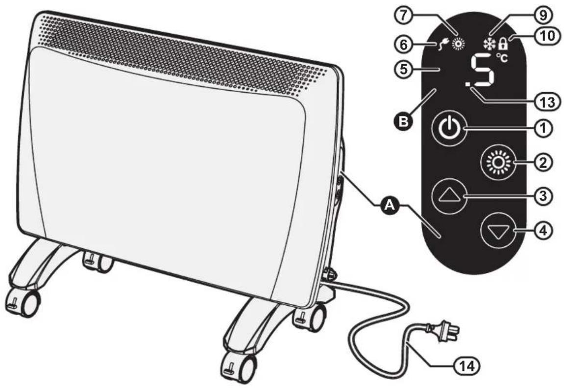
ANTI-FROST PROTECTION FUNCTION
If the set temperature ⑤ is set to 5 °C then the constant frost protection program will be activated and the constant frost protection (snowflake symbol) indicator ⑨ will be illuminated.
This is useful during winter in alpine areas where the ambient temperature is likely to fall below 5^ C.
ELECTRONIC LOCK FUNCTION
The Lock function is designed to prevent accidental operations and small children from altering the heater settings.
To Activate the Lock
Press the 'Up' ③ and 'Down' ④ buttons simultaneously until the padlock symbol ⑩ is displayed. All control functions are now locked and none of the buttons on the control will work.
To Deactivate the Lock
To deactivate the lock, repeat locking step above to return to normal operation

The Lock function is also de-activated if the heater is switched 'off' via the mains power.
TILT SWITCH
As a safety feature this heater is fitted with a tilt switch that automatically places the heater into standby mode if the appliance tilts more than 45^ , an audible warning is also provided in the form of a repeating 1 second chime and the interval digit will flash as a visual indication.
When the heater is returned to an upright position, normal operation will then be resumed.
CARE OF THE HEATER
Due to the ‘natural convection’ operating principle it is normal that some dust and fluff may build up at the air inlet and air outlet louvres over time. This will reduce operating effectiveness and may result in the appliance overheating if left for too long.
DO NOT use solvents to clean any parts.
To remove dust and clean the appliance:
- Unplug the electric plug of the heater from the socket outlet before commencing cleaning.
- Allow to cool down.
- Use a vacuum cleaner to remove any dust and fluff from the inlet and outlet louvres.
- All parts of the heater can be cleaned using a soft, damp cloth with some mild detergent (such as dishwashing liquid) if required.
- Ensure the heater is dry before reconnecting to the electricity supply.
ERROR CODES
Your Rinnai panel heater has a self diagnostic capability. If a fault occurs, an Error Code will flash on the two digits ⑤ of Digital LED display B, a repeating chime will also sound and the appliance will be prevented from operating.
Please quote the error code displayed when enquiring about service, for example:
Error Code E ☐ - Temperature sensor disconnection.
SERVICE AND REPAIR
If the electric power cord or plug are damaged, they must be replaced by Rinnai or a Rinnai appointed service agent.
There are no user serviceable parts inside the appliance. All service and repair work must be carried out by persons competent and permitted by law to do so.
If the heater requires service or repair contact your supplier or Rinnai Australia.
DISPOSAL
Electrical appliances may contain materials which, if handled or disposed off incorrectly, present a hazard to humans or the environment.
DO NOT dispose of your old appliance with your household waste. Dispose of your old appliance at your local community waste collection / recycling centre and ensure it presents no danger to children whilst being stored for disposal.
GENERAL
This heater is suitable for Do It Yourself installation. It can be either wall mounted (fixed installation) or freestanding by mounting castors in accordance with these instructions. A phillips head screwdriver is included for freestanding installation. For wall installation other tools and hardware may be required, depending on the wall material.
WALL INSTALLATION
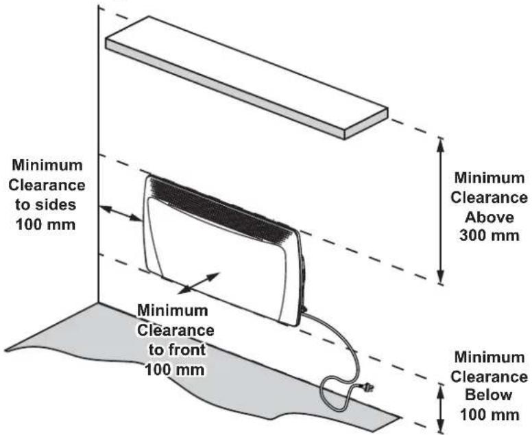
The clearance from the sides and front of the heater MUST BE at least 100mm and the clearance abover the heater MUST BE 300mm as shown in the diagram below.

- This heater MUST NOT be located immediately below a socket-outlet.
- This heater MUST be positioned within one metre of a socket-outlet to ensure the flexible cord and plug can reach it.
- This heater is NOT designed to be built in.
- DO NOT attach the castors to the heater base for wall installations.
-
The heater is suitable for installation in non-communal baths and shower areas or bathrooms. It is to be installed such that switches and other controls cannot be touched by a person in the bath or shower. Consult your licensed electrical trades person for installation in communal baths and shower areas or bathrooms.
-
Ensure the heater is unplugged from the power socket outlet before commencing wall mounting.
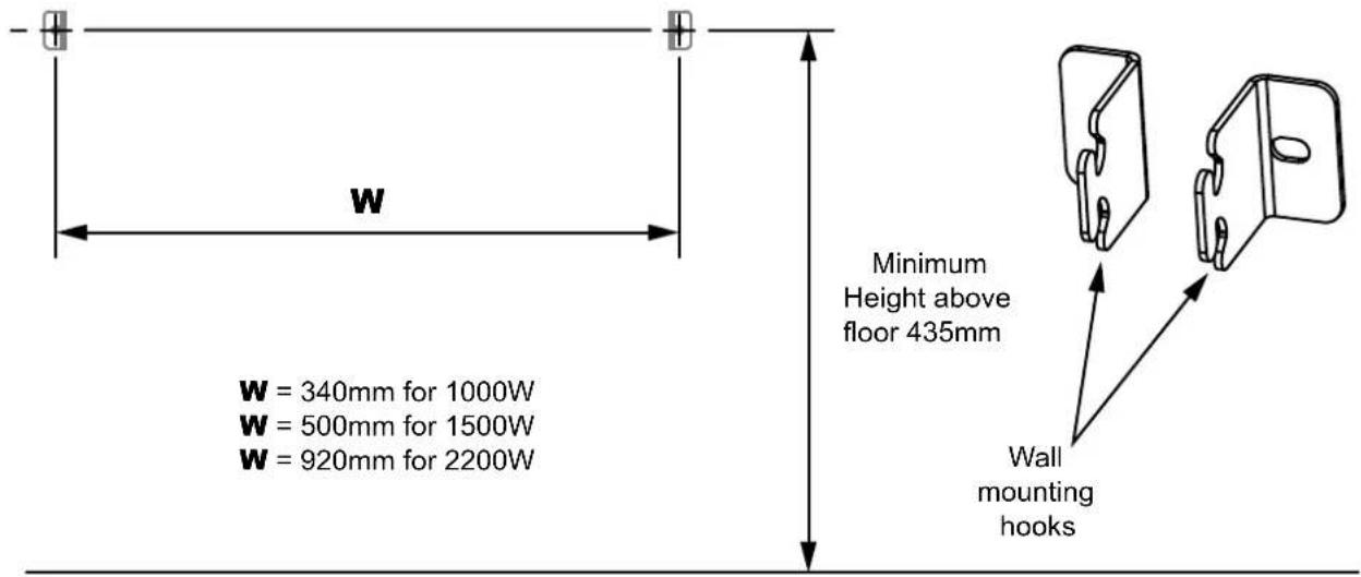
- Mount the supplied wall mounting hooks using the following dimensions to the wall using appropriate fixings, ensuring that the brackets are level and the minimum clearances as described above are observed.
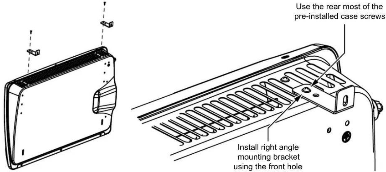
- Attach the supplied right angle mounting brackets to the bottom of the heater (front hole of bracket) using the rear most of the pre-installed case screws as shown below.
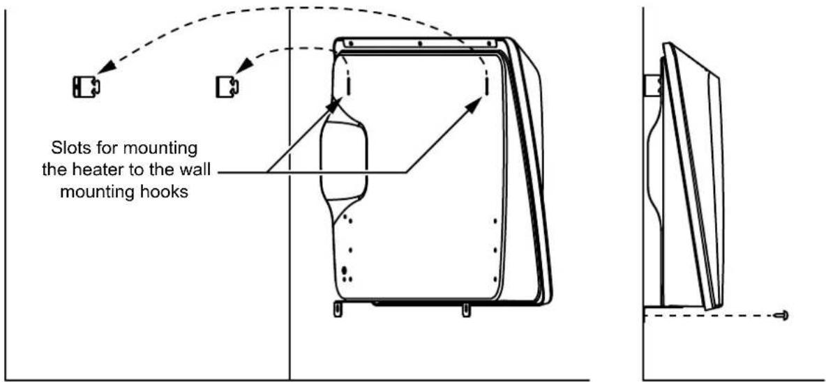
- Hang the heater using the slots located on the back of the appliance and secure the right angle mounting brackets to the wall with appropriate fixings as shown.
- Remove the cable tie from the flexible cord, then insert the power plug of the heater directly into a power socket outlet.
DO NOT bundle or coil the flexible cord to reduce it's length as overheating and subsequent fire hazard could result.
- The heater is now ready to be used as a free standing appliance. Refer to the operation section at the front of this manual for full instructions on how to use the heater.
FREESTANDING INSTALLATION
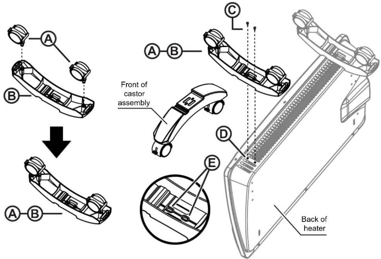
-
Be sure heater is unplugged before attempting to install the castor components.
-
Assemble the 2 castors ①the each castor foot by bushing the metal shaft fully home.
-
Place the heater in an 'upside down' position with the back of the heater facing you.
-
Remove the two of the pre-installed case screws from the base of the appliance.
-
With the front end of the castor assembly pointed towards the front of the heater, align the two holes ⑤ in the castor foot with the two holes in the base the appliance ⑧ and fix in place with the screws ⑨oved in step 4.
-
Repeat steps 4 and 5 to install the second castor assembly.
-
Rotate the heater back to the upright position and remove the cable tie from the flexible cord, then insert the power plug of the heater directly into a power socket outlet.

DO NOT bundle or coil the flexible cord to reduce it's length as overheating and subsequent fire hazard could result.
- The heater is now ready to be used as a free standing appliance. Refer to the operation section at the front of this manual for full instructions on how to use the heater.
Rinnai
Rinnai Australia Pty. Ltd. ABN 74 005 138 769
Head Office
100 Atlantic Drive,
Keysborough VIC 3173
P.O. Box 460
Braeside, Victoria 3195
Rinnai has a Service and Spare Parts network with personnel who are fully trained and equipped to give the best service on your Rinnai appliance. If your appliance requires service, please call our National Help Line.
Product Sales and Service - National
Phone: 1300 555 545* Fax: 1300 555 655*
Technical Helpline and Spare Parts
National (Mon-Fri 8am - 5.30pm EST)
Phone: 1300 555 545* Fax: 1300 300 141*
*Cost of a local call higher from mobile or public phones.
E-mail: enquiry@rinnai.com.au
For further information visit: www.rinnai.com.au

- WARRANTY, FEATURES & SPECIFICATIONS....5
- SAFETY & IMPORTANT POINTS....6
- HOW TO OPERATE THE HEATER....7
- INSTALLATION....12
- CONTACT INFORMATION ....16
- WARRANTY
- FEATURES
- UNPACKING THE APPLIANCE
- WHAT'S IN THE BOX
- SAFETY
- CONNECTING THE POWER
- OPERATION
- ANTI-FROST PROTECTION FUNCTION
- ELECTRONIC LOCK FUNCTION
- To Activate the Lock
- To Deactivate the Lock
- TILT SWITCH
- CARE OF THE HEATER
- ERROR CODES
- SERVICE AND REPAIR
- DISPOSAL
- GENERAL
- WALL INSTALLATION
- FREESTANDING INSTALLATION
- Rinnai
Brand : Rinnai
Model : DEPH-22DTW
Category : Heating