
ET-MDN12G10 - Uncategorized PANASONIC - Free user manual and instructions
Find the device manual for free ET-MDN12G10 PANASONIC in PDF.

| Product Type | 12G-SDI Interface Board for Commercial Use |
| Brand | Panasonic |
| Model | ET-MDN12G10 |
| Dimensions (W x H x D) | 151 mm x 38.5 mm x 142 mm |
| Weight | 400 g |
| Compatible Projectors | PT-RQ32K series, PT-RQ13K series (as of December 2017, firmware ≥ 3.00) |
| Slot Type | SLOT NX (Panasonic proprietary) |
| Input Terminals | 4 x BNC (IN 1, IN 2, IN 3, IN 4) |
| Output Terminals | 2 x BNC (active through, same as IN 2 and IN 4) |
| Supported SDI Signals | SD-SDI, HD-SDI, 3G-SDI, 6G-SDI (IN 1, IN 3 only), 12G-SDI (IN 1, IN 3 only) |
| Power Supply | Powered via projector slot (no external power required) |
| Installation | Requires qualified technician; turn off projector before installation |
| Included Accessories | 4 screws (XSB3+8FN) – spare for slot cover |
| Safety Precautions | Do not spill water, disassemble, or use in humid/dusty/hot locations |
| Handling | Avoid touching connector; discharge static before handling |
| Disposal | Follow local regulations; consult dealer |
| Importer (EU) | Panasonic Marketing Europe GmbH, Hamburg, Germany |
| Maximum Cable Length (SDI) | SD/HD/3G: 150 m; 6G: 80 m (110 m with L-5.5CUHD); 12G: 50 m (100 m with L-5.5CUHD in Input mode) |
| Supported Dual/Quad Link | Dual/Quad link HD-SDI, 3G-SDI, 6G-SDI |
| Maintenance | Keep dry; clean with dry cloth; avoid static |
Frequently Asked Questions - ET-MDN12G10 PANASONIC
User questions about ET-MDN12G10 PANASONIC
0 question about this device. Answer the ones you know or ask your own.
Ask a new question about this device
Download the instructions for your Uncategorized in PDF format for free! Find your manual ET-MDN12G10 - PANASONIC and take your electronic device back in hand. On this page are published all the documents necessary for the use of your device. ET-MDN12G10 by PANASONIC.
USER MANUAL ET-MDN12G10 PANASONIC
Operating Instructions
Interface Board for 12G-SDI Commercial Use
Model No. ET-MDN12G10
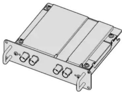
natural_image
Technical line drawing of a mechanical or electronic device casing with multiple connectors and mounting brackets (no text or symbols)ENGLISH
Thank you for purchasing this Panasonic product.
■ Before using this product, please read these “Operating Instructions” and the “Operating Instructions” of the projector carefully and save the manuals for future use.
■ Before using this product, be sure to read "Read this fi rst!"page 3).
4K
PROFESSIONAL
Contents
Read this first!
Precautions for use
Supported projector
About the handling of the product
Disposal
Accessories
Part names and functions
Installing the Interface Board
Before installing or removing the Interface Board
How to install the Interface Board
How to remove the Interface Board
Specifications
Read this first!
WARNING:
Do not spill water on this product or allow this product to get wet.
Doing so may cause fire, electric shock, or malfunction due to short circuit or overheating.
- Do not place a container with liquid close to this product.
- Consult your dealer when liquid such as water is spilled on this product.
Do not place the supplied screws in a location that a child can reach.
Accidentally swallowing them can cause a physical harm.
- Seek a medical advice immediately if a child might have swallowed a screw.
Do not disassemble or modify.
Doing so may cause electric shock or fire. It may also cause a malfunction.
CAUTION:
Do not place this product in a location with excessive humidity or dust, or in a location exposed to oil smoke or steam.
Doing so may cause fire or electric shock.
Do not place this product in extremely hot location.
Doing so may deteriorate the part, or may cause fire.
- Do not install or store in a location with direct sunlight or close to the heating device, etc.
Turn off the power and disconnect the power plug from the outlet when installing or removing this product to/from the projector.
Failure to do so may cause electric shock.
Importer's name and address within the European Union
Panasonic Marketing Europe GmbH
Panasonic Testing Centre
Winsbergring 15, 22525 Hamburg, Germany
Precautions for use
This product is a 12G-SDI signal compatible interface board for use installed in a Panasonic projector.
Supported projector
PT-RQ32K series, PT-RQ13K series
(As of December 2017)
Note
- Products other than the above may also be supported. Check the Operating Instructions of your projector.
- If the main version of the firmware of the PT-RQ32K or PT-RQ13K is less than 3.00, this interface board cannot be used. Update the firmware to the latest version before use. Check the update procedure by accessing the page containing the latest information on the firmware at the Panasonic website (https://panasonic.net/cns/projector/pass/).
About the handling of the product
■ Do not touch the connector section of the Interface Board directly with your hands.
The component may be damaged by the static electricity. Handle this product after removing the static in your body by touching the surrounding metal, etc.
Disposal
To dispose of the product, ask your local authorities or dealer for correct methods of disposal.
Accessories
Make sure that the following accessories are provided with your product. Numbers enclosed in < > show the number of accessories.
Screw <4>
(XSB3+8FN)

Attention
- Appropriately discard the packaging material after unpacking the product.
- For missing accessories, consult your dealer.
- Store small parts in an appropriate manner, and keep them away from small children.
4 - ENGLISH
Note
- The supplied screws are spare. Use them when a screw to fix the slot cover of the projector is lost.
- The model numbers of accessories are subject to change without prior notice.
Part names and functions
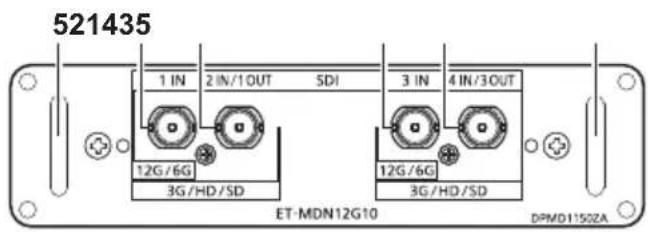
1 terminal
This is a terminal to input SDI signals (SD-SDI / HD-SDI / 3G-SDI / 6G-SDI / 12G-SDI).
2 terminal
This is a terminal to input SDI signals (SD-SDI / HD-SDI / 3G-SDI). It is also an active through terminal to output the SDI signals (SD-SDI / HD-SDI / 3G-SDI / 6G-SDI / 12G-SDI) input to the
3 terminal
This is a terminal to input SDI signals (SD-SDI / HD-SDI / 3G-SDI / 6G-SDI / 12G-SDI).
4 terminal
This is a terminal to input SDI signals (SD-SDI / HD-SDI / 3G-SDI). It is also an active through terminal to output the SDI signals (SD-SDI / HD-SDI / 3G-SDI / 6G-SDI / 12G-SDI) input to the
5 Handle
Note
- The
terminal and terminal do not support the input of 6G-SDI signals and 12G-SDI signals. - To use the
terminal and terminal as output terminals, you need to change the settings of the projector. Check the Operating Instructions of your projector.
Installing the Interface Board
It is recommended to ask a qualified technician to install or remove the Interface Board to a projector. A malfunction may occur due to static electricity. Consult your dealer.
Before installing or removing the Interface Board
- Always turn off the power of the projector before installing or removing the Interface Board.
- Make sure to follow the procedure described in the Operating Instructions of your projector when turning off the power.
- Do not touch the connector section of the Interface Board directly with your hands.
-The component may be damaged by the static electricity.
- Remove the static charge from your body by touching the surrounding metal, etc., in advance to prevent the static electricity damage.
- Take care not to get injured when installing or removing the Interface Board.
- Hands may be injured by the opening of the blank slot of the projector or the edge of the bracket of the Interface Board.
- When installing the Interface Board to the slot, insert it into the connector straight and slowly.
- It may not operate or cause malfunction if it is not correctly installed.
• Install and use this interface board in one of the
How to install the Interface Board
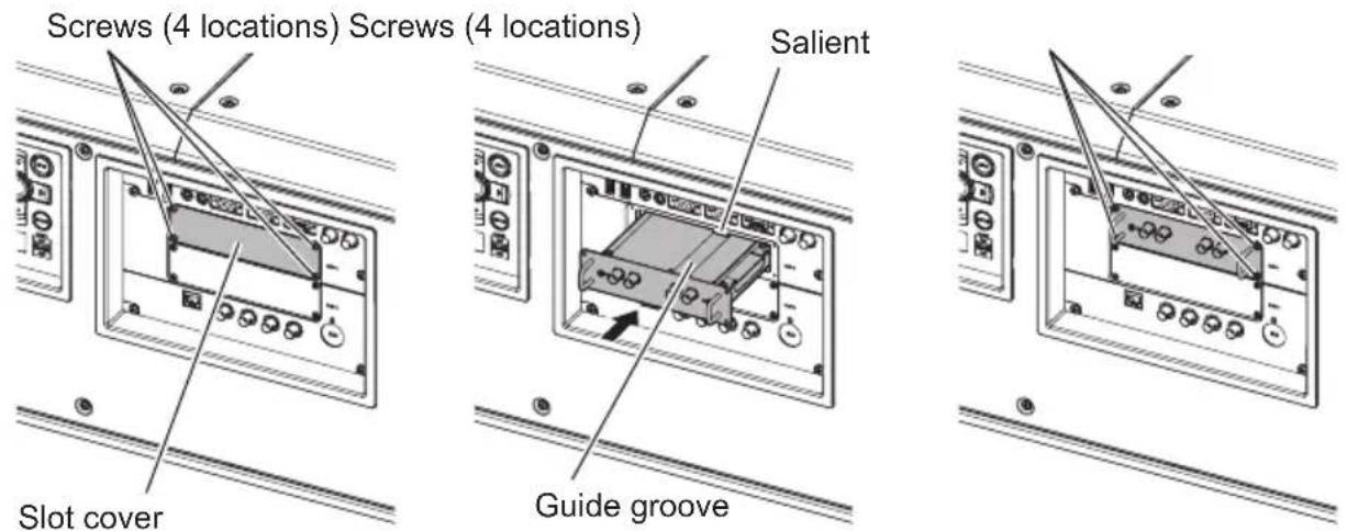
1) Remove the slot cover. (Fig. 1)
- Remove the four screws fixing the slot cover of the projector by rotating counterclockwise with a Phillips screwdriver. The removed screws are used to fix the Interface Board.
- When removing the fourth screw, hold the slot cover with your hand so it will not fall.
- To replace from other Interface Board, remove the Interface Board following the procedure in "How to remove the Interface Board"
(→ page 7).
6 - ENGLISH
2) Install the Interface Board to the projector. (Fig. 2)
- Insert the guide groove of the Interface Board aligned to the salient of the slot. Insert the bracket firmly all the way in.
3) Fix the Interface Board. (Fig. 3)
- Tighten and fix with the four screws removed in Step 1).
Attention
- The removed slot cover is required when the unnecessary Interface Board is removed. Store it so it can be attached in the future.
How to remove the Interface Board
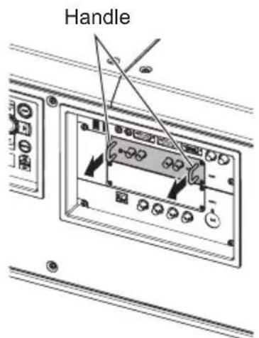
Fig. 1
1) Remove the Interface Board. (Fig. 1)
- Remove the four screws fixing the Interface Board by rotating counterclockwise with a Phillips screwdriver. The removed screws are used to fix the slot cover.
- Hold the handle of the Interface Board and remove it slowly.
2) Attach the slot cover.
- Attach the stored slot cover to the blank slot, and tighten and fix with the four screws removed in Step 1).
Attention
•Always attach the slot cover on the blank slot.
- Store the removed Interface Board inside an antistatic bag.
Specifications
| Compatible slot SLOT NX | specification | |
| Connection terminals / supported signals | Inputs | BNC 4 lines(terminal,terminal,terminal)Single link SD-SDI signal, SMPTE ST 259 standard compliantSingle link HD-SDI signal, SMPTE ST 292 standard compliantSingle link 3G-SDI signal, SMPTE ST 424 and 425-2 standards compliantSingle link 6G-SDI signal, SMPTE ST 2081-1 and 2081-10 standards compliantSupported byterminal andterminal onlySingle link 12G-SDI signal, SMPTE ST 2082-1 and 2082-10 standards compliantSupported byterminal andterminal onlyDual link HD-SDI signal, SMPTE ST 372 standard compliantterminal: Link A signal /terminal: Link B signalDual link 3G-SDI signal, SMPTE ST 425-3 standard compliantterminal: Link 1 signal /terminal: Link 2 signalDual link 6G-SDI signal, SMPTE ST 2081-11 standard compliantterminal: Link 1 signal /terminal: Link 2 signalQuad link HD-SDI signalterminal: Link 1 signal /terminal: Link 2 signal /terminal: Link 3 signal /terminal: Link 4 signalQuad link 3G-SDI signal, SMPTE ST 425-5 standard compliantterminal: Link 1 signal /terminal: Link 2 signal /terminal: Link 3 signal /terminal: Link 4 signal |
| Outputs | BNC 2 line (also functions as input terminal)(terminal,terminal)Performs active through output of the signals input to theterminal andterminal. | |
| Dimensions | Width 151 mm (5-15/16") | |
| Height 38.5 mm (1-17/32") | ||
| Depth 142 mm (5-19/32") | ||
| Weight | 400 g (14.1 ozs.) | |
Note
- "SLOT NX" is a name of the slot unique to Panasonic supporting the signal input for the 4K image.
- The video signal that can actually display will vary depending on the projector that the Interface Board is installed. For details, refer to the Operating Instructions of your projector.
- When the projector is in the standby state, signals are not output from the
terminal and terminal. - To ensure images are transmitted correctly, use 5C-FB or higher (5C-FB, 7C-FB, etc.), Belden 1694A or higher, or Canare Electric L-5.5CUHD for the connection cable. Furthermore, the maximum lengths of cables that can be used are as follows. However, these maximum cable lengths are provided as a guide, and are not a guarantee of transmission distances.
-SD-SDI signal, HD-SDI signal, and 3G-SDI signal: 150 m
-6G-SDI signal: 80 m (110 m if L-5.5CUHD is used.) - When 12G-SDI, differs depending on the setting of [Display Options] menu → [SLOT IN] → [SDI Mode] of the projector.
When [SDI Mode] is set to [Input], 50 m (100 m if L-5.5CUHD is used.)
When [SDI Mode] is set to [Output], 50 m (90 m if L-5.5CUHD is used.) - When [Display Options] menu → [SLOT IN] → [SDI Mode] of the projector is set to [Output], attach a terminating resistor (75 Ω) to the terminal to which a device is not connected as an output destination.
- For the BNC connector of the connection cable, use one that supports the coaxial cable and types of signal to be used.
Product Information (for Turkey only)

Web Site : https://panasonic.net/cns/projector/
© Panasonic Corporation 2017
Panasonic System Communications Company of North America
5th Floor, Two Riverfront Plaza, Newark, NJ 07102-5490
TEL: (877) 803 - 8492
Panasonic Canada Inc.
5770 Ambler Drive, Mississauga, Ontario L4W 2T3
TEL: (905) 624 - 5010

- Operating Instructions
- Contents
- Read this first!
- Precautions for use
- Installing the Interface Board
- Specifications
- WARNING:
- CAUTION:
- Supported projector
- Note
- About the handling of the product
- ■ Do not touch the connector section of the Interface Board directly with your hands.
- Disposal
- Accessories
- Attention
- - ENGLISH
- Part names and functions
- terminal
- terminal
- terminal
- terminal
- Handle
- Before installing or removing the Interface Board
- How to install the Interface Board
- 1) Remove the slot cover. (Fig. 1)
- - ENGLISH
- 2) Install the Interface Board to the projector. (Fig. 2)
- 3) Fix the Interface Board. (Fig. 3)
- How to remove the Interface Board
- 1) Remove the Interface Board. (Fig. 1)
- 2) Attach the slot cover.
- Product Information (for Turkey only)
Brand : PANASONIC
Model : ET-MDN12G10
Category : Uncategorized