
AW-UE150KP - Security Camera PANASONIC - Free user manual and instructions
Find the device manual for free AW-UE150KP PANASONIC in PDF.

| Product Type | Professional PTZ Security Camera |
| Brand and Model | Panasonic AW-UE150KP |
| Dimensions (approx.) | 220 x 220 x 350 mm (with bracket) |
| Weight (approx.) | 5.5 kg (without accessories) |
| Power Supply | PoE+ (IEEE 802.3at) or AC adapter (not included) |
| Maximum Resolution | 4K (3840x2160) at 60 fps |
| Main Features | Motorized Pan/Tilt/Zoom, SDI and HDMI outputs, IP streaming, auto tracking, area masking |
| Viewing Angle | Horizontal: approx. 70°, Vertical: approx. 40° (depending on zoom) |
| Optical Zoom | 20x (typical for this range) |
| Connectivity | 3G-SDI, HDMI, Ethernet (RJ45), audio input, RS-232C |
| Protection | IP65 (weather resistance, indoor/outdoor) |
| Operating Temperature | -10°C to +45°C |
| Installation | Wall or ceiling mount with provided bracket or optional mount |
| Cleaning | Wipe with a soft, dry cloth; do not use solvents |
| Included Accessories | Mounting bracket, mounting screws, safety wire, user manual |
| Safety | Installation by qualified professional only; check mounting annually |
| Repairability | Spare parts available from manufacturer; repair by qualified personnel |
| Standards | Compliant with CISPR 32 Class A, WEEE directive |
Frequently Asked Questions - AW-UE150KP PANASONIC
User questions about AW-UE150KP PANASONIC
0 question about this device. Answer the ones you know or ask your own.
Ask a new question about this device
Download the instructions for your Security Camera in PDF format for free! Find your manual AW-UE150KP - PANASONIC and take your electronic device back in hand. On this page are published all the documents necessary for the use of your device. AW-UE150KP by PANASONIC.
USER MANUAL AW-UE150KP PANASONIC
Operating Instructions
Excerpted Version
Installation Instructions provided
natural_image
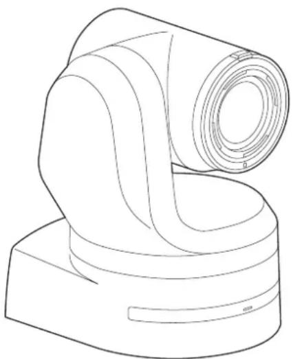
Line drawing of a mechanical device with a cylindrical component and curved base (no text or symbols)4K Integrated Camera
Model No.
Model No.
Model No.
Model No.
AW-UE150WP AW-UE150KP AW-UE150WE AW-UE150KE
HDMI™
| ENGLISH Excerpted Version | Before installing and using this product, be sure to read “Read this first!” (pages 4, 25 to 27).This manual contains information excerpted from the Operating Instructions.For more information, please visit the Panasonic website (https://pro-av.panasonic.net/manual/en/index.html), and refer to the Operating Instructions. |
| FRANÇAIS | Avant d’installer et d’utiliser cet appareil, s’assurer de lire la section « Lire ces informations en premier ! » (pages 4, 28 à 30).Pour de plus amples informations, visiter le site Web de Panasonic (https://pro-av.panasonic.net/manual/en/index.html) et consulter le mode d’emploi et les instructions d’installation. |
| ESPAÑOL | Antes de instalar y usar este producto, asegúrese de leer “Lea esto primero!” (páginas 4, 31 a 33).Si desea obtener más información, visite el sitio web de Panasonic (https://pro-av.panasonic.net/manual/en/index.html) y consulte las instrucciones de funcionamiento y las instrucciones de instalación. |
| DEUTSCH | Bitte lesen Sie sorgfältig „Bitte lesen Sie zuerst diesen Hinweis!“ vor der Installation und Nutzung dieses Produkts. (Seiten 5, 34 bis 35).Weitere Informationen finden Sie auf der Panasonic-Webseite (https://pro-av.panasonic.net/manual/en/index.html), in der Bedienungsanleitung und in der Installationsanleitung. |
| ITALIANO | Prima di installare e utilizzare il prodotto, assicurarsi di leggere “Leggere prima quanto segue!” (pagine 5, 36 a 37).Per maggiori informazioni, visitare il sito Web Panasonic (https://pro-av.panasonic.net/manual/en/index.html) e fare riferimento alle istruzioni per l’uso e alle istruzioni per l’installazione. |
| PYCCKII | Перед установкой и использованием данного изделия ознакомьтесь с информацией в разделе «Прочитайте нижеследующее до начала эксплуатации!» (стр. 5, 38 до 39).Для получения дополнительной информации посетите веб-сайт Panasonic (https://pro-av.panasonic.net/manual/en/index.html) и обратитесь к инструкции по эксплуатации и инструкции по установке. |
Before operating this product, please read the instructions carefully and save this manual for future use.
PJ EJ
SS1018YM0 -FJ
Printed in Japan
ENGLISH
DVQX1709ZA
| български | Посетете следния уебсайт относно информация за безопасността и важни уведомления за продукта. |
| Hrvatski | Za sigurnosne informacije i važne obavijesti o proizvodu posjetite sljedeću internetsku stranicu. |
| Čeština | Na následujícím webu najdete bezpečnostní informace a düležité poznámky k tomuto produktu. |
| Dansk | Besog følgende webside for sikkerhedsinformation og vigtige bemærkninger vedrørende produktet. |
| Nederlands | Ga naar de volgende website voor veiligheidsinformatie en belangrijke meldingen over het product. |
| Eesti | Toodet puudutava ohutusteabe ja oluliste märkuste saamiseks külastage järgmist veebilehte. |
| Suomi | Käy seuraavalla verkkosivulla saadaksesi turvallisuustietoja ja tärkeitä tietoja liittyen laitteeseen. |
| Ελληνικά | Για πληροφορίες σχετικά με θέματα ασφάλειας και σημαντικές εἰδοποιήσεις που αφορούν το προϊόν σας, επισκεφτείτε τον ιστότοπο που ακολουθεί. |
| Magyar | A termékkel kapcsolatos biztonsági információkért és fontos értesítésekért látogasson el az alábbi weboldalra. |
| Latviešu | Lai iegūtu informāciju par drošību un skatītu svarīgus paziņojumus par šo produktu, apmeklējiet tālāk norādīto tīmekļa vietni. |
| Lietuvių | Jei reikia saugos informacijos ir svarbių pranešimų apie gaminį, apsilankykite toliau nurodytoje svetainėje. |
| Polski | Informacje o bezpieczeństwie i ważne informacje o produkcie znajdują się w ponižszej witrynie internetowej. |
| Português | Consulte o seguinte website para as informações de segurança e importantes notificações sobre o produto. |
| Română | Vizitați urmātoarea pagină web pentru informații de securitate și notificări importante cu privire la produs. |
| Slovensky | Pre bezpečnostné informácie a dôležité oznámenia súvisiace s produktom navštívte túto webovú stránku. |
| Slovenščina | Za varnostne informacije in pomembna obvestila v zvezi z izdelkom obiščite naslednje spletno mesto. |
| Svenska | Besök följande webbplats för säkerhetsinformation och viktiga meddelanden om produkten. |
https://pro-av.panasonic.net/manual/en/index.html
■ Trademarks and registered trademarks
- Microsoft®, Windows®, Windows® 7, Windows® 10, Microsoft Edge, Internet Explorer®, ActiveX® and DirectX® are either registered trademarks or trademarks of Microsoft Corporation in the United States and other countries.
- Apple, Mac, Mac OS, OS X, iPhone, iPad, and Safari are registered trademarks of Apple Inc., in the United States and other countries.
- Android™ and Chrome™ browser are trademarks of Google LLC.
- Intel® and Intel® Core™ are trademarks or registered trademarks of Intel Corporation in the United States and other countries.
- Adobe® and Reader® are either registered trademarks or trademarks of Adobe Systems Incorporated in the United States and/or other countries.
- The terms HDMI and HDMI High-Definition Multimedia Interface, and the HDMI Logo are trademarks or registered trademarks of HDMI Licensing Administrator, Inc. in the United States and other countries.
- NDI® is a registered trademark of NewTek, Inc.
- Other names of companies and products contained in these Operating Instructions may be trademarks or registered trademarks of their respective owners.
■ About copyright and licence
Distributing, copying, disassembling, reverse compiling, reverse engineering, and also exporting in violation of export laws of the software provided with this unit are expressly prohibited.
Abbreviations
The following abbreviations are used in this manual.
- Microsoft® Windows® 7 Professional SP1 32/64-bit is abbreviated to "Windows 7".
- Windows® Internet Explorer® 11 32/64-bit is abbreviated to "Internet Explorer".
For the purposes of this manual, the model numbers of the units are given as listed in the table below.
| Model number of unit | Model number given in manual |
| AW-UE150WP | AW-UE150 |
| AW-UE150KP | |
| AW-UE150WE | |
| AW-UE150KE | |
| AW-RP150G AW-RP150 | |
■ Illustrations and screen displays featured in the manual
- What is shown in the manual's illustrations and screen displays may differ from how it is actually appears.
- Functions which can be used by Windows Internet Explorer 11 only are indicated using the Windows I.E.11 mark.
- The screenshots are used in accordance with the guidelines of Microsoft Corporation.
Installation Instructions
Read this first! 4
Before installation 8
IR ID switch settings 8
Service switch settings....8
How to install and connect the unit....9
When using the WV-Q105A (optional accessory).... 13
Removing the camera....14
Stand-alone installation
(when the mount bracket is going to be used)....15
Stand-alone installation
(when the mount bracket is not going to be used)....17
When installing the unit on a desktop 17
When mounting the unit on a tripod 17
Connections
Connecting an NDI|HX compatible switcher 18
Connections with a controller (AW-RP150) 19
System example 1 (Serial control) 20
System example 2 (IP control) 21
System example 3 (IP image transmission, PoE++).... 22
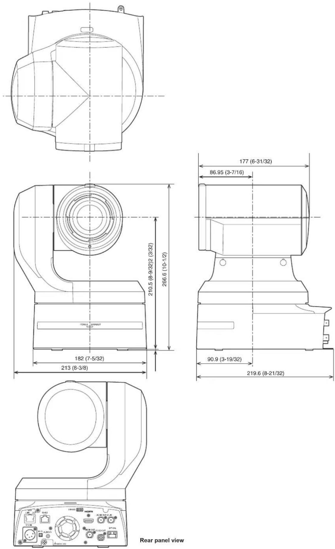
Appearance.
23
Operating Instructions
Read this first! 24
Note on grounding 24
Read this first! (For AW-UE150WP, AW-UE150KP)....25
Read this first! (For AW-UE150WE, AW-UE150KE)....26
(Pour AW-UE150WP, AW-UE150KP)....28
(Pour AW-UE150WE, AW-UE150KE)....29
Lea esto primero! (Para AW-UE150WP, AW-UE150KP)....31
Lea esto primero! (Para AW-UE150WE, AW-UE150KE)....32
Computer requirements 40
Disclaimer of warranty 41
Network security 41
Features...... 42
Accessories 43
Optional accessories 43
Operating precautions 44
Wireless remote control (optional accessory).... 46
Parts and their functions 47
Camera unit 47
Wireless remote control: AW-RM50G (not supplied) 54
Setting the remote control IDs 56
Network settings.... 57
Use the Easy IP Setup Software to establish the unit's settings..... 57
Setting the initial account....58
Installing the plug-in viewer software 58
How to turn the power on and off 59
Turning the power on....59
Turning the power off....59
Troubleshooting 60
Specifications....69
Index 70
WARNING:
To prevent injury, this apparatus must be securely attached to the floor/wall in accordance with the installation instructions.
WARNING:
Installation should only be performed by qualified installation personnel.
Improper installation may result in the entire apparatus falling down and causing injury.
CAUTION:
This camera intended for use only with the Mount Bracket enclosed with the unit and Panasonic Direct Ceiling Mount Bracket, WV-Q105A.
Use with other apparatus is capable of resulting in instability causing possible injury.

indicates safety information.
Panasonic does not accept any responsibility for accident or damage during installation if procedure in this manual is not followed.
To installation personnel
Read the "Installation Instructions" thoroughly and then perform the operation correctly and safely.
Also, always read the "Read this first!" (→ page 4) of this manual as they contain important information.
After the installation, give the "Installation Instructions" to the customer to save for future use.
■ Ensure that the installation work complies with the technical standards governing electrical equipment.
■ This unit is for indoor use only.
It cannot be used outdoors.
Avoid installation in a location where the unit will be exposed to direct sunlight for extended periods or near a cooling or heating appliance.
Otherwise, deformation, discoloration, malfunctioning and/or problems in operation may result. Operate the unit where it will not be splashed or sprayed by water.
■ Use the unit with an installation where the unit is suspended from an overhead surface or with a stand-alone installation.
Do not use the unit on its side or tilted at an angle.
- Be absolutely sure to use the four bracket mounting screws (M4) for mounting the mount bracket. These are supplied with the unit.
Do not use wood screws, nails, etc.
In the case of a concrete ceiling, secure the unit using anchor bolts (for M4) or AY plug bolts (for M4).
Recommended clamping torque
- The withdrawal strength of the mounting location for each screw must be at least 461 N {47 kgf}.
- When mounting the unit on a ceiling made of plasterboard, for instance, if it is not strong enough to support its weight, either reinforce the ceiling adequately or use the WV-Q105A direct ceiling mount bracket, which is sold separately.
- When using a mount bracket which is sold separately, read the handling instructions.
- Do not hold the camera head while undertaking the installation work. Doing so may cause malfunctioning.
OKNGOKNG
natural_image
Illustration of hands performing a bandage technique with tape roll (no text or symbols)Desktop installation Hanging installation
■ Concerning the installation location
Install the unit in a stable location which will not be susceptible to shaking. If the unit is installed in a location which is susceptible to shaking, this will cause the unit's images to shake in turn. Install the unit after conferring in detail with your dealer. Install the unit on a ceiling that is strong enough (such as a concrete ceiling).
If the unit is to be installed on a ceiling which is not strong enough, reinforce the ceiling sufficiently first.
- Do not install or use the unit in the following kinds of locations.
- On walls (where the unit would be installed sideways)
- In locations (including places such as under the eaves of a building) where the unit would be directly exposed to rain or water
- In locations such as kitchens where there are high concentrations of steam and grease
- In outdoor locations or hot places where the temperature will exceed 40 °C (104 °F)
- In cold locations where the temperature will drop below 0 °C (32 °F)
• In locations where the humidity will exceed 85%
- In locations where chemicals are used such as near swimming pools
- At sea, in coastal areas or in locations where corrosive gases are emitted
- In locations where radiation, X-rays, or strong radio waves or magnetic fields are generated
- In locations where the unit would be subject to a great deal of vibration such as on board a vehicle or ship (this unit is not designed to be used in vehicles)
- In locations where the temperature is subject to sudden changes such as near the air outlet of an air conditioner or near a door which allows the outside air to come in
■ What to avoid to ensure that the unit will perform stably over a prolonged period
- Using the unit for a prolonged period in a location with high temperature and humidity levels will cause its parts to deteriorate and shorten its service life.
- Ensure that a cooling unit or heating unit will not blow any air directly toward the installation location.
- Be absolutely sure to use the supplied brackets and screws to install the camera.
- Do not mount the unit by employing any methods other than those specified.
- Do not remodel the mounting bracket or mounting screws provided with the unit.
| AW-UE150 main unit | Mounting conditions | |||||
| Applicable mount bracket Mounting onto the ceiling | ||||||
| Mass Model No. | Mass Mounting | Recommended screws | No. of screws | Minimum withdrawal strength (per screw) | ||
| Approx. 4.2 kg (9.24 lb) (excluding mount bracket) | Direct mount (supplied accessory) | Approx. 0.35 kg (0.77 lb) | Hanging/Desktop | M4 screws (supplied accessory) | 4 | 461 N {47 kgf} · Ensure that the mounting strength can support a weight that is at least five times the total mass of the equipment, including the camera's main unit. |
| WV-Q105A (optional accessory) | Approx. 0.15 kg (0.33 lb) | For ceiling | M4 screws (supplied with the WV-Q105A) | 4 | ||
■ Before installation, always disconnect the DC connector
When installing, always use the supplied components. Do not disassemble or modify the wall mount adaptor.
■ Tightening up the mounting screws
- Tighten up the screws and bolts securely to the degree that is appropriate for each of the materials used in the mounting location and structures.
- After tightening up the screws and bolts, check that there is no unsteadiness and that the parts have been tightened securely.
- Use the specified tools and tighten the screws firmly.
- Tighten up the screws using the specified torque driver. Do not use electrical drivers or impact drivers.
When the unit is no longer going to be used, do not leave it lying around, but be absolutely sure to dispose of it properly.
For details on how to remove the unit, refer to "Removing the camera" ( page 14).
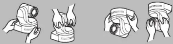
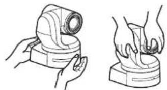
- When installing, transferring or disposing of the unit, be absolutely sure to hold it by its pedestal area.
Problems may result if the camera head is held or rotated.
- Do not attach a filter, hood, extender or other parts to the unit.
■ Install the external DC power supply near the main power outlet, and position it in such a way that its power plug can be plugged into and unplugged from the outlet easily.
When connecting the external DC power supply to a power outlet on the ceiling or on any other surface where dust may collect, wipe off the dust on the power plug at periodic intervals as an anti-tracking measure.
Power switch
This unit does not have a power switch. When the power is supplied, the pan, tilt, zoom and focusing operations are performed. ^*1 Before proceeding with maintenance, be absolutely sure to disconnect the power plug from the power outlet.
*1 Under factory default conditions, the unit will be in Standby mode when power is supplied for the first time. (Status display lamp: Lit orange)
- When the power supply is cut off while the unit is in Standby mode, the unit will be in Standby mode the next time power is supplied. (Status display lamp: Lit orange)
- When the power supply is cut off while the unit is in Power ON mode, the unit will be in Power ON mode the next time power is supplied. (Status display lamp: Lit green)
(For details, refer to "How to turn the power on and off" (→ page 59).)
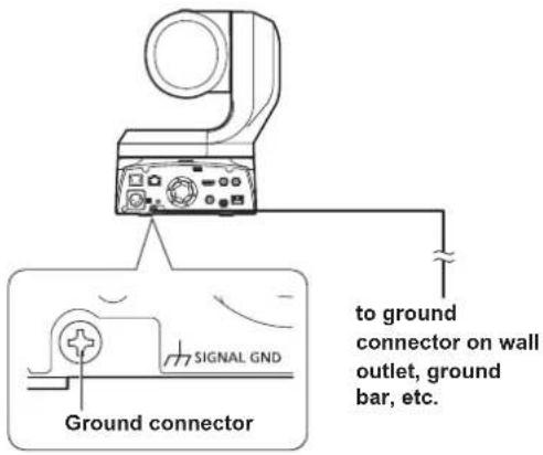
Grounding
Before operating the unit, check that SIGNAL GND has been securely grounded.
If there is a possibility of noise interference
Either wire the cables so that the power cable (ceiling light cord) of AC 100 V*2 (AC 220 V*3) or more, and the signal cable are placed at least 1 meter (3.3 ft) apart.
Alternatively run each cable through its own metal conduit. (The metal conduits must be grounded.)
*2 For AW-UE150WP, AW-UE150KP
*3 For AW-UE150WE, AW-UE150KE
■ Radio signal interference
If the unit is positioned near a TV or radio transmitting antenna or a strong electrical field or magnetic field (such as that generated by a motor, transformer or power lines), its images may be distorted and/or the images may be affected by noise.
■ When connecting the cables, ensure that the connector areas will not be subject to any load.
Doing so may cause malfunctioning.
■ Allowing the generated heat to escape
This unit allows the heat generated inside to escape from its surfaces.
Do not install the unit in a location where it will be surrounded by walls or other surfaces and where heat will be trapped.
In addition, the heat is dissipated to the bottom panel which will warm up over time: This is normal and not indicative of any trouble.
■ PoE++ power supplies
Use a PoE++ [IEEE802.3bt Draft ver.2.0 standard (LLDP not supported)] compatible hub or power supply device.
Network settings
The network function of this unit does not work unless an initial account is set up (except when using the Easy IP Setup Software ( page 57)). A personal computer is required to set up an initial account. ( page 58)
- Network connection with AW-RP150 also requires setup of an initial account. When an initial account is not set up, AW-RP150 can detect but cannot control this unit.
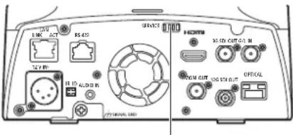
Be sure to configure the switches on the connector panel and bottom of the unit before installing it. Configuring the switches after the unit is installed may prove difficult.
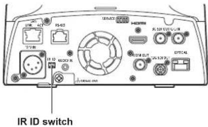
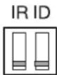
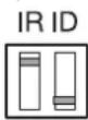
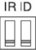
IR ID switch settings
The IR ID switches are located on the connector panel of the unit.
| CAM1 CAM2 | CAM3 CAM4 | ||
IR ID | IR ID | IR ID | IR ID |
These are used to select the ID of the wireless remote control (optional accessory). (→ page 56)
The IR ID switch settings "CAM1" to "CAM4" correspond to the
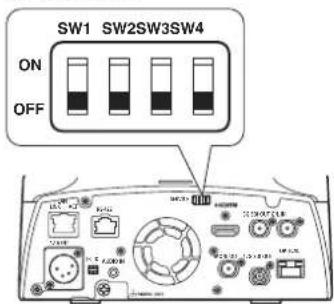
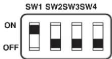
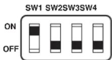
Service switch settings
The service switches are located on the connector panel of the unit. Perform switch settings before turning the unit on.
Service switch
| Function Factory settings | ||
| SW1 SW | Switches for initialization(Refer to the explanations in "Initialization 1" and "Initialization 2") | OFF |
| SW2 | Always leave at OFF (used for factory adjustments) | OFF |
| SW3 OFF | ||
| SW4 OFF | ||
Initialization 1
- Reset the user authentication settings and host authentication settings for network connection.
(This will delete all the registered user information (IDs/passwords) and host information (IP addresses).) - With the IR ID switches and service switches set as shown below, turn on the power of the unit.
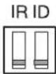
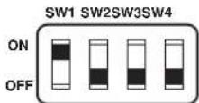
- When initialization is complete, the status display lamp on the front of the unit blinks green. Restart the unit to confirm the initialization.
Initialization 2
- The unit is reset to the state it was in at the time of purchase. (All camera menu setting values and network setting values are reset.)
- With the IR ID switches and service switches set as shown below, turn on the power of the unit.
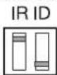
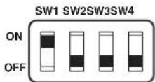
- When initialization is complete, the status display lamp on the front of the unit blinks green. Restart the unit to confirm the initialization.
Be absolutely sure to read through the "Read this first!" (→ page 4) and "Installation precautions" (→ pages 6 to 7).
The procedure given here is for the kind of installation where the unit is suspended from an overhead surface, but the same steps are followed for a stand-alone installation.
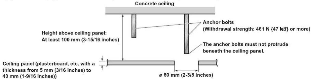
If the ceiling panel is not strong enough to bear the unit's weight, use the kind of mount bracket that is supported by anchor bolts between the concrete ceiling and ceiling panel. The unit supports the WV-Q105A direct ceiling mount bracket which is used solely for combination cameras. Use this bracket to install the unit. (→ page 13) In a case like this, the holes (ø 60 mm (ø 2-3/8 inches)) for installing the direct ceiling mount bracket on the ceiling must be drilled in the ceiling panel. It is also recommended that you provide an inspection space or opening for access purposes in the area near where the equipment is installed in order to facilitate installation and the wiring connections work. For details on supplied accessories, refer to the page 43.
1. Check the mounting space.
- Refer to the illustration, and determine where the unit is to be installed and in which direction it should be mounted. Factor in the unit mounting area and include space for the wires extending from its rear panel.
- The asterisk (*) in the illustration marks the position and dimensions of the hole for mounting the mount bracket.
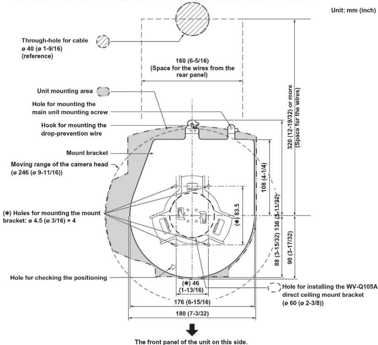
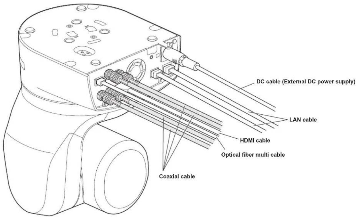
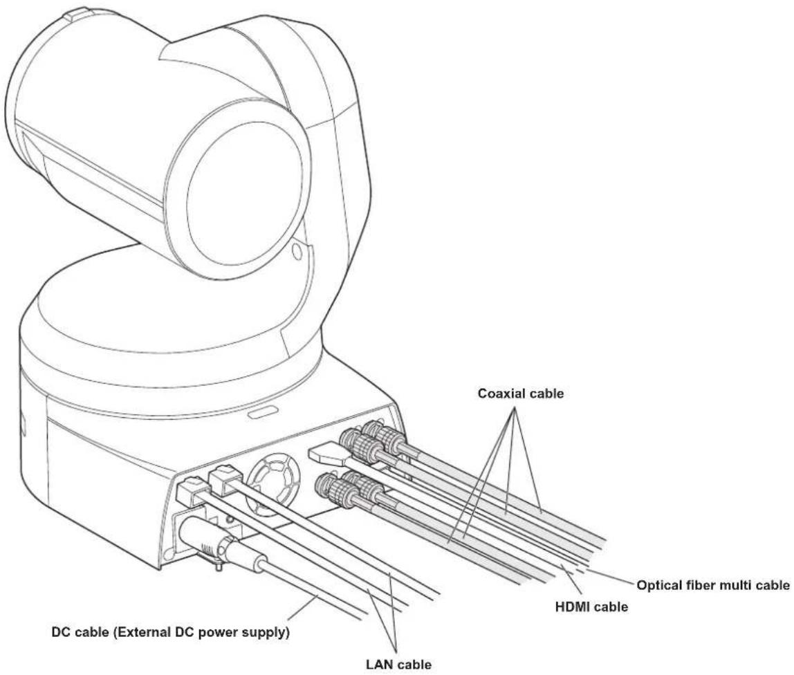
- Before proceeding to install and connect the main unit, connect the LAN cable, HDMI cable, optical fiber multi cable and coaxial cables in the space above the ceiling panel, and then pass the cables through the cable holes.
- For a power outlet which is used on the ceiling, be absolutely sure to take measures to deal with the tracking that may be caused by the accumulation of dust and other foreign matter.
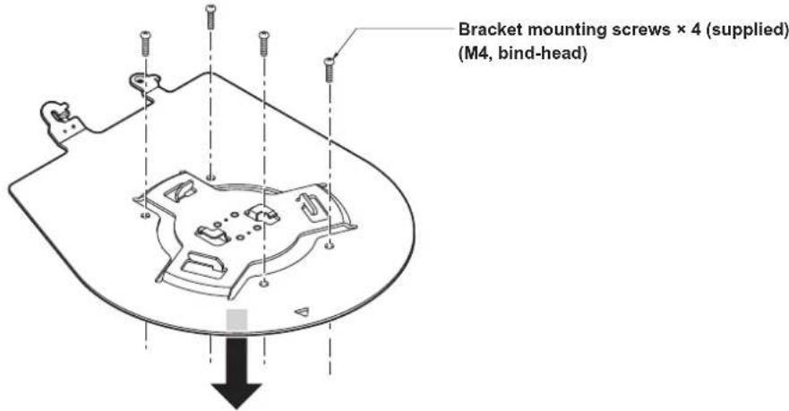
2. Mount the mount bracket onto the installation surface.
- Use the bracket mounting screws (M4, bind-head: 10 mm (13/32 inches) long) supplied with the unit.
- For proper clamping torque, securely attach the screws using the specified tools.
| Screw diameter | Clamping torque |
| M4 1.47 | N · m {15 kgf · cm} |
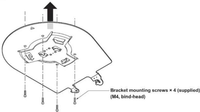
- Use only the screws supplied with the unit. Do not use any other screws such as wood screws, nails, etc.
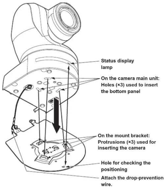
3. Attach the drop-prevention wire.
- Loop the circle part of the drop-prevention wire, which has been attached to the bottom panel of the unit, around the end of the hook part of the mount bracket.
- Pull the drop-prevention wire, and check that it has been attached securely to the hook.
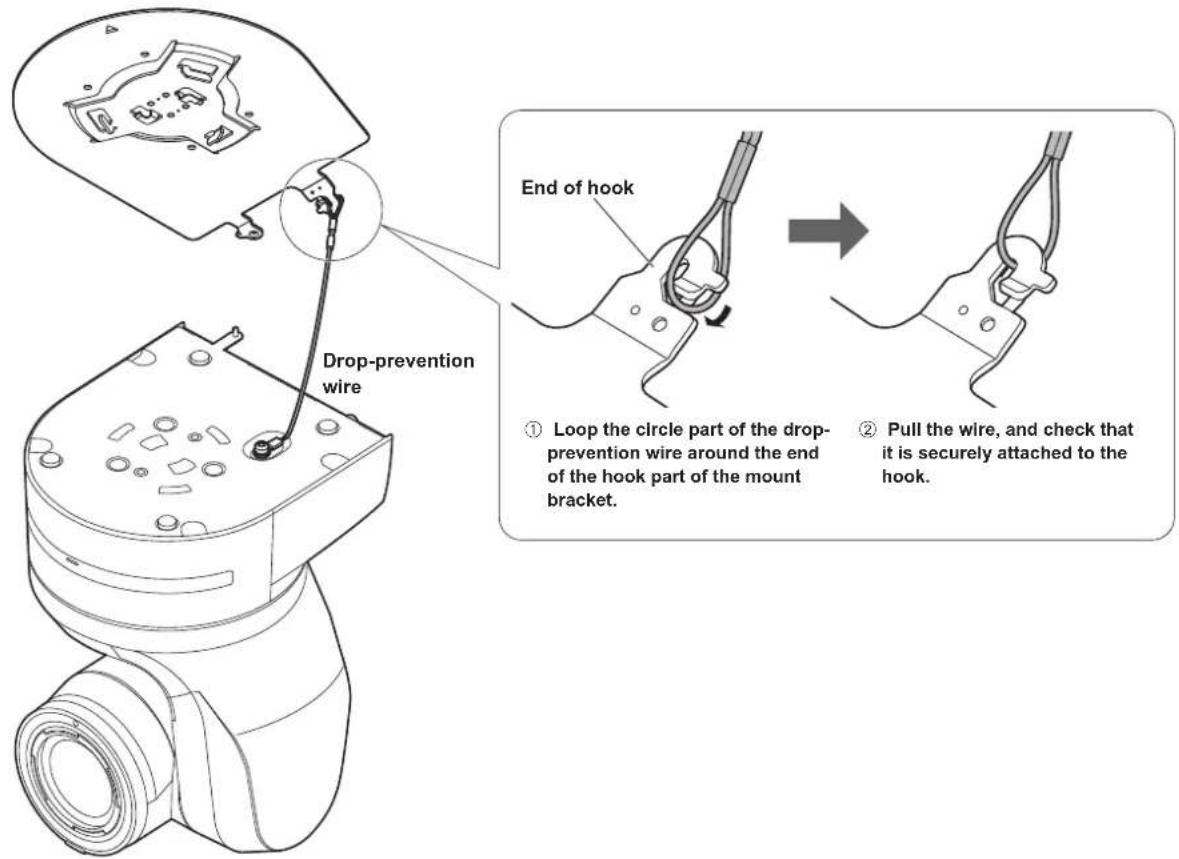
- Do not do this work while holding the camera head since doing so may result in malfunctioning of the unit.
- The drop-prevention wire is designed to be used for installation where the unit is suspended from an overhead surface so do not subject it to the weight of units other than the unit.
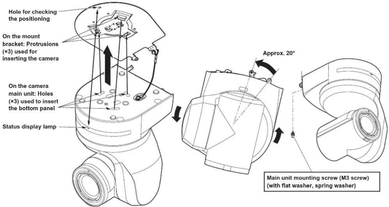
4. Mount the unit.
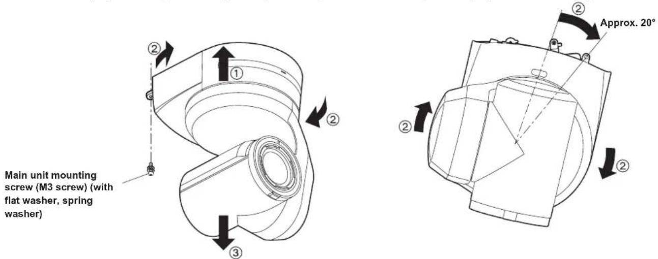
- Align the position of the hole for checking the positioning with the status display lamp.
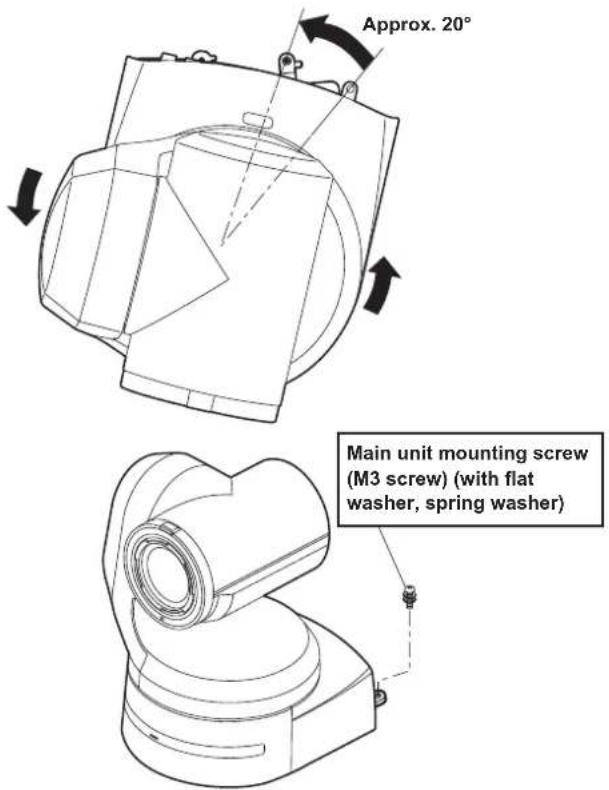
- Align the holes on the camera main unit used to insert the bottom panel with the protrusions on the mount bracket used for inserting the camera, push the bracket and camera firmly together, and rotate the main unit by about 20 degrees in the direction of the arrow.
- Secure the mount bracket to the unit using the main unit mounting screw (M3) as supplied.
- Attach the mount bracket securely with the prescribed tool using the clamping torque below.
- Be absolutely sure to verify that none of the screws are loose.
| Screw diameter | Clamping torque |
| M3 0.78 | N · m {8 kgf · cm} |
- Do not do this work while holding the camera head since doing so may result in malfunctioning of the unit.
- Use only the screws supplied. Do not use any other screws.
- Check that the unit has been mounted securely with no tilting or wobbling.
- The unit must be secured without fail using the main unit mounting screw before any of the cables are connected.
5. Check the mounting.
Check out the following points.
- The main unit mounting screw must be mounted securely.
- The unit must not tilt, and it must be mounted exactly.
- The unit must be securely installed.
- The unit pedestal part must not rotate even when an attempt is made to turn it.
6. Connect the rear panel connectors.
- Do not connect PoE cable to the RS-422 port.
- When Optical output is to be used, connect the recommended optical fiber module. (→ page 49)
- For details on recommended products, refer to the catalog or consult your local dealer.
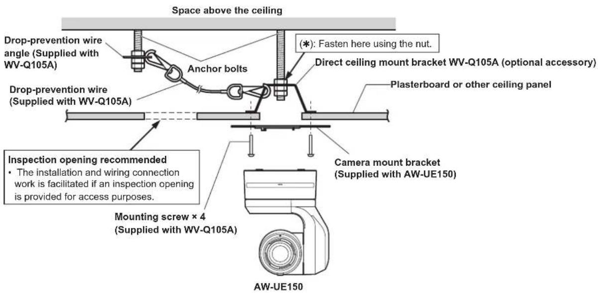
When using the WV-Q105A (optional accessory)
It is recommended that you provide an inspection opening or other such space for access purposes in the area near where the equipment is installed in order to facilitate installation and the wiring connections work.
Before mounting the mount bracket, check that the installation location is strong enough to withstand the total mass (approx. 4.7 kg (10.34 lb)) which will be exerted once the camera is mounted.
Use the mount bracket where the space between the ceiling panel and the concrete ceiling is at least 100 mm (3-15/16 inches) high.
The bracket can be mounted where the thickness of the ceiling panel ranges from 5 mm (3/16 inches) to 40 mm (1-9/16 inches).
The drop-prevention wire (supplied with the WV-Q105A) must be used when mounting the direct ceiling mount bracket.
- Refer to the Operating Instructions of the WV-Q105A direct ceiling mount bracket, and attach the WV-Q105A as well as the drop-prevention wire angle and drop-prevention wire supplied with the WV-Q105A to the anchor bolts.
Mounting the anchor bolts and direct ceiling mount bracket (*)
This job is facilitated if the direct ceiling mount bracket is loosely secured to the ceiling panel in one place, and the direct ceiling mount bracket and anchor bolts are vertically aligned before the nuts are tightened up.
- First, remove the screws which were loosely fastened in step 1, and then align the camera mount bracket of the AW-UE150 with the screw holes in the WV-Q105A direct ceiling mount bracket and mount it in place.
- Use the mounting screws (the M4-L60 Phillips head screws with adhesive) supplied with the WV-Q105A as the mounting screws.
-
Install the AW-UE150 camera by following the procedure starting with step 3 on page 10.
-
Turn off the circuit breaker and power.
- Disconnect the cables.
Disconnect the DC cable, LAN cable, and HDMI cable, etc. - Remove the main unit mounting screw used to secure the unit and mount bracket.
- Push the unit (①). Turn it approximately 20 degrees away from the installed position (②), and remove it (③).
- Do not do this work while holding the camera head since doing so may result in malfunctioning of the unit.
- Disengage the drop-prevention wire from the mount bracket.
natural_image
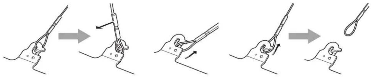
Sequence of four diagrams showing a cable being lifted, with no text or symbols present.① Pull the dropprevention wire in the direction shown by the arrow above.
② Twist the wire, and remove the wire loop through the opening in the hook.
③ Pull the wire in the direction shown by the arrow above, and simply pull it out.
Stand-alone installation (when the mount bracket is going to be used)
The same steps are followed as for the kind of installation where the unit is suspended from an overhead surface ( pages 9 to 12).
1. Check the mounting space.
- As with installing the unit suspended from an overhead surface, carefully check the space where the unit will be mounted, and then decide if it is appropriate to install the unit in that space.
2. Mount the mount bracket onto the installation surface.
3. Attach the drop-prevention wire.
4. Mount the unit.
- Align the position of the hole for checking the positioning with the status display lamp.
- Align the holes on the camera main unit used to insert the bottom panel with the protrusions on the mount bracket used for inserting the camera, push the bracket and camera firmly together, and rotate the main unit by about 20 degrees in the direction of the arrow.
- Secure the mount bracket to the unit using the main unit mounting screw (M3) as supplied.
5. Check the mounting.
6. Connect the rear panel connectors.
- Do not connect PoE cable to the RS-422 port.
- When Optical output is to be used, connect the recommended optical fiber module. (→ page 49)
- For details on recommended products, refer to the catalog or consult your local dealer.
Stand-alone installation (when the mount bracket is not going to be used)
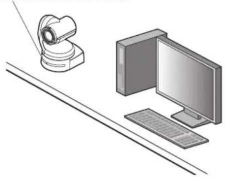
When installing the unit on a desktop
Place the unit flat on the surface.
• Install the unit in a stable location which will not be susceptible to shaking. If the unit is installed in a location which is susceptible to shaking, this will cause the unit's images to shake in turn.
- Take care not to allow the unit to fall or otherwise be damaged during installation.
- When carrying the unit, do not hold it by its head.
- Do not take hold of the camera head or rotate it. Doing so may cause malfunctioning.
• Take care not to pull the connected cables. Doing so may cause the unit to fall and/or it may result in injury.
Ensure that the unit will not fall off.
natural_image
Illustration of a desktop computer setup with monitor, keyboard, and remote camera (no text or symbols)OKMG
natural_image
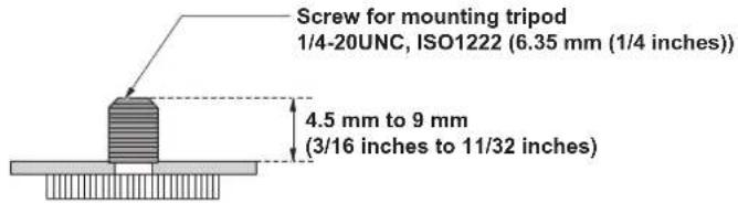
Illustration of hands performing a mechanical press or stamping operation (no text or symbols present)When mounting the unit on a tripod
Attach the tripod to the threaded holes for mounting the camera on the camera's bottom panel.
Place the tripod on a completely flat and level surface.
Tighten the screws by hand to mount the tripod securely.
Use screw for mounting the tripod that satisfy the following standard.
- Do not install the unit where people will be passing back and forth.
- When using the unit mounted on a tripod, do not put the tripod high above the floor level.
- Mount the unit securely so there is no looseness. Looseness may cause the unit to fall off and/or result in injuries.
- When the unit is going to be used for a prolonged period of time, take steps to ensure that the unit will not topple or fall over and that it will not fall off or fall down. After using the unit, restore the installation location to its original state without delay.
Connecting an NDI|HX compatible switcher
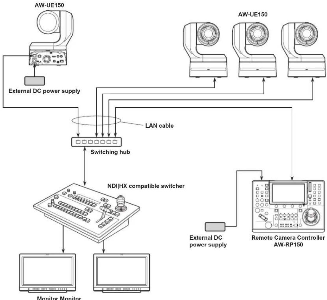
flowchart
graph TD
    A["External DC power supply"] --> B["Switching hub"]
    C["External DC power supply"] --> B
    D["External DC power supply"] --> E["Remote Camera Controller AW-RP150"]
    F["External DC power supply"] --> G["NDI|HX compatible switcher"]
    H["Monitor Monitor"] --> I["Switching hub"]
    J["AW-UE150"] --> K["Switching hub"]
    L["AW-UE150"] --> M["Switching hub"]
    N["AW-UE150"] --> O["Switching hub"]
    P["AW-UE150"] --> Q["Switching hub"]
    R["LAN cable"] --> B
    S["External DC power supply"] --> T["Remote Camera Controller AW-RP150"]
Connections with a controller (AW-RP150)
■ Example of connection for the function for cropping 4K images to HD images
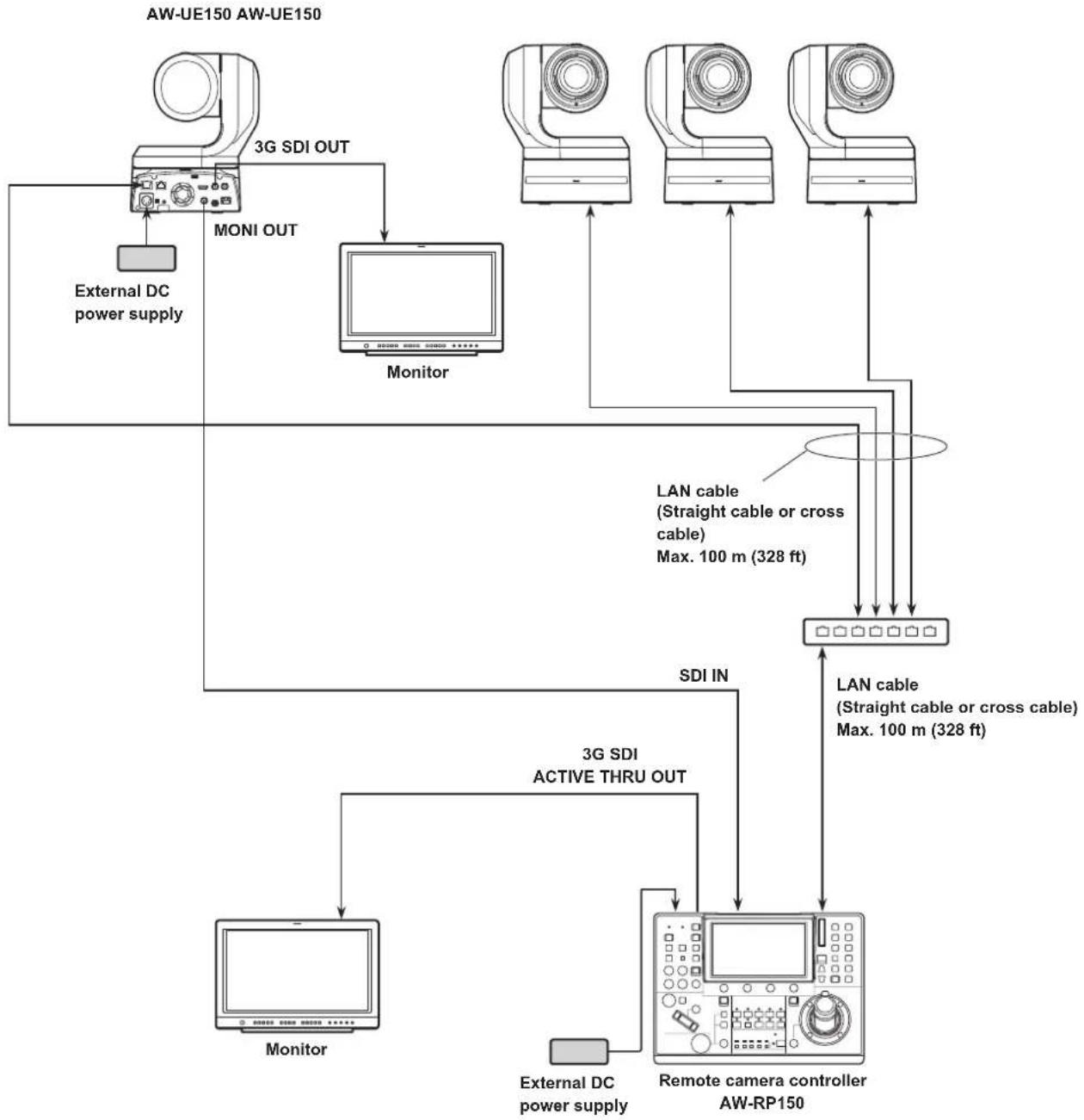
flowchart
graph TD
    A["AW-UE150 AW-UE150"] --> B["MONI OUT"]
    B --> C["Monitor"]
    C --> D["External DC power supply"]
    D --> E["3G SDI OUT"]
    E --> F["Monitor"]
    F --> G["External DC power supply"]
    G --> H["3G SDI ACTIVE THRU OUT"]
    H --> I["Monitor"]
    I --> J["External DC power supply"]
    J --> K["Remote camera controller AW-RP150"]
    K --> L["LAN cable (Straight cable or cross cable) Max. 100 m (328 ft)"]
    L --> M["LAN cable (Straight cable or cross cable) Max. 100 m (328 ft)"]
    M --> N["External DC power supply"]
    N --> O["Monitor"]
    O --> P["External DC power supply"]
- Use a category 5e cable for the LAN cable.
System example 1 (Serial control)
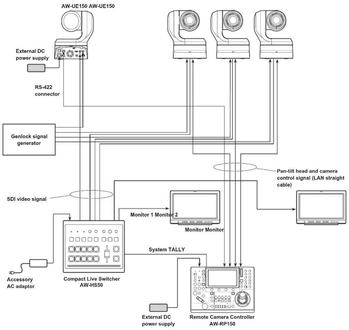
flowchart
graph TD
    A["External DC power supply"] --> B["RS-422 connector"]
    B --> C["Genlock signal generator"]
    C --> D["Compact Live Switcher AW-HS50"]
    D --> E["Monitor 1 Monitor 2"]
    E --> F["Remote Camera Controller AW-RP150"]
    F --> G["External DC power supply"]
    G --> H["System TALLY"]
    H --> I["Pan-tilt head and camera control signal (LAN straight cable)"]
    I --> J["Computer"]
System example 2 (IP control)
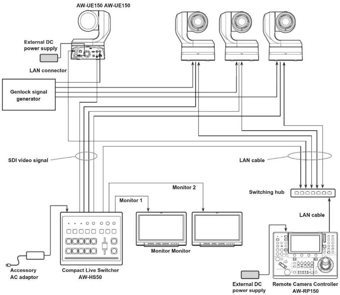
flowchart
graph TD
    A["External DC power supply"] --> B["Compact Live Switcher AW-HS50"]
    C["LAN connector"] --> B
    D["Genlock signal generator"] --> B
    E["SDI video signal"] --> B
    F["Switching hub"] --> G["Remote Camera Controller AW-RP150"]
    H["External DC power supply"] --> I["External DC power supply"]
    J["Monitor 1"] --> B
    K["Monitor 2"] --> B
    L["Monitor Monitor"] --> B
    M["External DC power supply"] --> N["External DC power supply"]
    O["LAN cable"] --> P["LAN cable"]
    Q["External DC power supply"] --> R["External DC power supply"]
    S["External DC power supply"] --> T["External DC power supply"]
    U["External DC power supply"] --> V["External DC power supply"]
System example 3 (IP image transmission, PoE++)
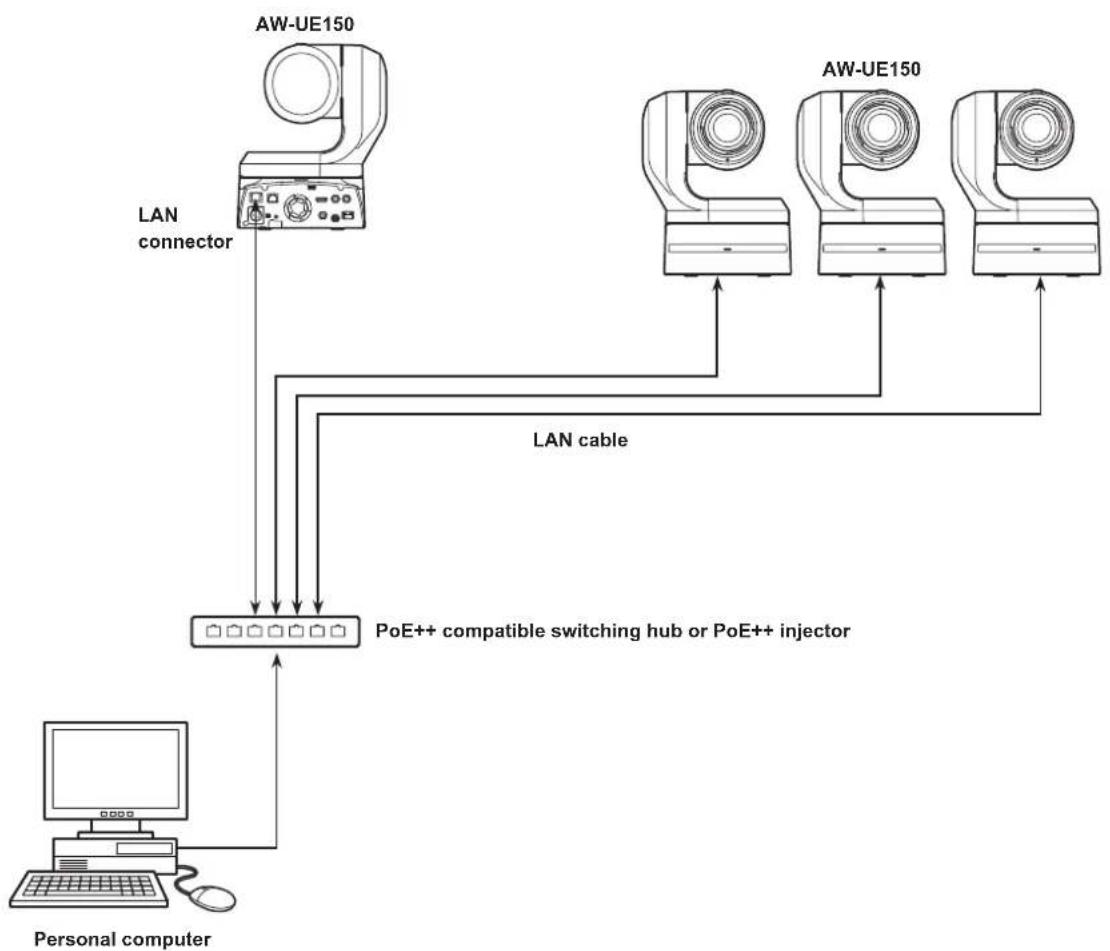
flowchart
graph TD
    A["Personal computer"] --> B["PoE++ compatible switching hub or PoE++ injector"]
    C["AW-UE150"] --> D["LAN connector"]
    E["AW-UE150"] --> F["LAN cable"]
    G["AW-UE150"] --> H["LAN cable"]
    I["AW-UE150"] --> J["LAN cable"]
    K["AW-UE150"] --> L["LAN cable"]
Unit: mm (inch)
Note on grounding
- Ground the unit via the
WARNING:
- To reduce the risk of fire or electric shock, do not expose this equipment to rain or moisture.
- To reduce the risk of fire or electric shock, keep this equipment away from all liquids. Use and store only in locations which are not exposed to the risk of dripping or splashing liquids, and do not place any liquid containers on top of the equipment.
WARNING:
Always keep the main unit mounting screw, bracket mounting screws and drop-prevention wire mounting screw out of the reach of infants and small children.
CAUTION:
Do not remove panel covers by unscrewing.
To reduce the risk of electric shock, do not remove the covers.
No user serviceable parts inside.
Refer servicing to qualified service personnel.
CAUTION:
In order to maintain adequate ventilation, do not install or place this unit in a bookcase, built-in cabinet or any other confined space. To prevent risk of electric shock or fire hazard due to overheating, ensure that curtains and any other materials do not obstruct the ventilation.
CAUTION:
To reduce the risk of fire or electric shock and annoying interference, use the recommended accessories only.
CAUTION:
Check the installation at least once a year. An improper installation could cause the unit to fall off resulting in personal injury.
CAUTION:
Do not pick up and move the unit while the tripod is attached. The fitting may break under the weight of the tripod, which may result in injury.

indicates safety information.
FCC NOTICE (USA)
Declaration of Conformity
Model Number: AW-UE150P
Trade Name: Panasonic
Responsible Party: Panasonic Corporation of North America
Two Riverfront Plaza, Newark, NJ 07102
Support contact: 1-800-524-1448
This device complies with part 15 of the FCC Rules.
Operation is subject to the following two conditions:
(1) This device may not cause harmful interference, and (2) this device must accept any interference received, including interference that may cause undesired operation.
CAUTION:
This equipment has been tested and found to comply with the limits for a class A digital device, pursuant to Part 15 of the FCC Rules.
These limits are designed to provide reasonable protection against harmful interference when the equipment is operated in a commercial environment. This equipment generates, uses, and can radiate radio frequency energy and, if not installed and used in accordance with the instruction manual, may cause harmful interference to radio communications.
Operation of this equipment in a residential area is likely to cause harmful interference in which case the user will be required to correct the interference at his own expense.
FCC Warning:
To assure continued FCC emission limit compliance, follow the attached installation instructions and the user must use only shielded interface cables when connecting to host computer or peripheral devices. Also, any unauthorized changes or modifications to this equipment could void the user's authority to operate this device.
NOTIFICATION (Canada)
CAN ICES-3 (A)/NMB-3(A)

indicates safety information.
WARNING:
- To reduce the risk of fire or electric shock, do not expose this equipment to rain or moisture.
- To reduce the risk of fire or electric shock, keep this equipment away from all liquids. Use and store only in locations which are not exposed to the risk of dripping or splashing liquids, and do not place any liquid containers on top of the equipment.
WARNING:
Always keep the main unit mounting screw, bracket mounting screws and drop-prevention wire mounting screw out of the reach of infants and small children.
WARNING:
This equipment is compliment with Class A of CISPR 32. In a residential environment this equipment may cause radio interference.
CAUTION:
Do not remove panel covers by unscrewing.
To reduce the risk of electric shock, do not remove the covers.
No user serviceable parts inside.
Refer servicing to qualified service personnel.
CAUTION:
In order to maintain adequate ventilation, do not install or place this unit in a bookcase, built-in cabinet or any other confined space. To prevent risk of electric shock or fire hazard due to overheating, ensure that curtains and any other materials do not obstruct the ventilation.
CAUTION:
To reduce the risk of fire or electric shock and annoying interference, use the recommended accessories only.
CAUTION:
Check the installation at least once a year. An improper installation could cause the unit to fall off resulting in personal injury.
CAUTION:
Do not pick up and move the unit while the tripod is attached. The fitting may break under the weight of the tripod, which may result in injury.

indicates safety information.
Turkey Only
AEEE Complies with Directive of Turkey.
EMC NOTICE FOR THE PURCHASER/USER OF THE APPARATUS
1. Pre-requisite conditions to achieving compliance with the above standards
<1> Peripheral equipment to be connected to the apparatus and special connecting cables
- The purchaser/user is urged to use only equipment which has been recommended by us as peripheral equipment to be connected to the apparatus.
- The purchaser/user is urged to use only the connecting cables described below.
<2> For the connecting cables, use shielded cables which suit the intended purpose of the apparatus.
• Video signal connecting cables
Use double shielded coaxial cables, which are designed for 75-ohm type high-frequency applications, for SDI (Serial Digital Interface). Coaxial cables, which are designed for 75-ohm type high-frequency applications, are recommended for analog video signals.
• Audio signal connecting cables
If your apparatus supports AES/EBU serial digital audio signals, use cables designed for AES/EBU.
Use shielded cables, which provide quality performance for high-frequency transmission applications, for analog audio signals.
- Other connecting cables (IEEE1394, USB)
Use double shielded cables, which provide quality performance for high-frequency applications, as connecting cables.
- When connecting to the DVI signal terminal, use a cable with a ferrite core.
- If your apparatus is supplied with ferrite core(s), they must be attached on cable(s) following instructions in this manual.
2. Performance level
The performance level of the apparatus is equivalent to or better than the performance level required by these standards. However, the apparatus may be adversely affected by interference if it is being used in an EMC environment, such as an area where strong electromagnetic fields are generated (by the presence of signal transmission towers, cellular phones, etc.). In order to minimize the adverse effects of the interference on the apparatus in cases like this, it is recommended that the following steps be taken with the apparatus being affected and with its operating environment:
-
Place the apparatus at a distance from the source of the interference.
-
Change the direction of the apparatus.
- Change the connection method used for the apparatus.
- Connect the apparatus to another power outlet where the power is not shared by any other appliances.
Disposal of Old Equipment
Only for European Union and countries with recycling systems
This symbol on the products, packaging, and/or accompanying documents means that used electrical and electronic products must not be mixed with general household waste.
For proper treatment, recovery and recycling of old products, please take them to applicable collection points in accordance with your national legislation.
By disposing of them correctly, you will help to save valuable resources and prevent any potential negative effects on human health and the environment. For more information about collection and recycling, please contact your local municipality, dealer or supplier.
Penalties may be applicable for incorrect disposal of this waste, in accordance with national legislation.
AVERTISSEMENT:
- This product is an all-in-one pan-tilt head remote camera that supports 4K/12G-SDI and is also compatible with 4K/60p format.
- Equipped with an optical 20x zoom lens and 4K-compatible MOS sensor, it is possible to record high-quality images with a high degree of realism with the horizontal resolution of 1600 lines. With its high sensitivity and built-in image-shake correction and night-mode functions, the unit can record in a wide range of environments.
- This product is compatible with NDI|HX technology of NewTek, Inc.
- The unit supports transmission of video to NewTek NDI|HX compatible software applications and hardware devices over a network.
- When a controller is connected, camera operations can be performed smoothly via IP control or serial control.
- The unit features a night mode that exposes subjects to infrared rays, making it possible to shoot even under low-light conditions.
- When the unit is connected to a personal computer via an IP network, it can be operated via a web browser.
- With a variety of 4K interfaces, there are individual outputs for HD and SDI, so the unit can be used flexibly in a wide range of situations as a 4K-compatible remote camera.
- Connection with a Panasonic camera controller is also possible via Panasonic's proprietary serial communication format.
- The unit is available in white (AW-UE150WP/AW-UE150WE) or black (AW-UE150KP/AW-UE150KE) to suit your intended application and environment.
Computer requirements
| CPU 7th Generation Intel | ^® CoreTM (Kaby Lake or later) |
| Memory For Windows: | 4 GB or moreFor Mac:4 GB or more |
| Network function 100BASE-T/TX or 1000BASE-T,RJ-45 connector | |
| Image display Resolution: 1920 × 1080 pixels or moreColor generation: True Color 24-bit or more | |
| Supported operating systems and web browsers | For Windows:Microsoft® Windows® 7, 10Windows® Internet Explorer® 1164-bit/32-bitMicrosoft EdgeGoogle Chrome |
| For Mac:Mac OS 10.13Safari 11Mac OS 10.12Safari 11Mac OS 10.11Safari 11Google Chrome | |
| For iPhone, iPad:iOS Safari | |
| For Android:Android OSGoogle Chrome | |
| Other Adobe | ^® Reader ^® (for viewing the operating instructions available on the website) |
IMPORTANT
- Failure to provide the required personal computer environment may slow down the delineation of the images on the screen, make it impossible for the web browser to work and cause other kinds of problems.
- Depending on the software version of the unit, an update may be necessary.
- For the latest information on compatible operating systems and web browsers, visit the support desk at the following website.
https://pro-av.panasonic.net/
Disclaimer of warranty
IN NO EVENT SHALL Panasonic Corporation BE LIABLE TO ANY PARTY OR ANY PERSON, EXCEPT FOR REPLACEMENT OR REASONABLE MAINTENANCE OF THE PRODUCT, FOR THE CASES, INCLUDING BUT NOT LIMITED TO BELOW:
① ANY DAMAGE AND LOSS, INCLUDING WITHOUT LIMITATION, DIRECT OR INDIRECT, SPECIAL, CONSEQUENTIAL OR EXEMPLARY, ARISING OUT OF OR RELATING TO THE PRODUCT;
② PERSONAL INJURY OR ANY DAMAGE CAUSED BY INAPPROPRIATE USE OR NEGLIGENT OPERATION OF THE USER;
③ UNAUTHORIZED DISASSEMBLE, REPAIR OR MODIFICATION OF THE PRODUCT BY THE USER;
④ INCONVENIENCE OR ANY LOSS ARISING WHEN IMAGES ARE NOT DISPLAYED, DUE TO ANY REASON OR CAUSE INCLUDING ANY FAILURE OR PROBLEM OF THE PRODUCT;
⑤ ANY PROBLEM, CONSEQUENTIAL INCONVENIENCE, OR LOSS OR DAMAGE, ARISING OUT OF THE SYSTEM COMBINED BY THE DEVICES OF THIRD PARTY;
⑥ ANY DEMANDS FOR COMPENSATION, CLAIMS, ETC. OCCASIONED BY THE INFRINGEMENT OF PRIVACY BY INDIVIDUALS OR ORGANIZATIONS WHOSE IMAGES WERE SHOT BY THE USER BECAUSE THESE IMAGES (INCLUDING THE RECORDINGS MADE) WERE MADE AVAILABLE BY THE USER BECAUSE IN THE PUBLIC DOMAIN FOR SOME REASON OR OTHER OR BECAUSE THE IMAGES ENDED UP BEING USED FOR PURPOSES OTHER THAN THE ONE DESCRIBED ABOVE;
⑦ LOSS OF REGISTERED DATA CAUSED BY ANY FAILURE.
Network security
As the unit intended to be used while connected to a network, the following security risks exist.
① Leakage or theft of information through the unit
② Unauthorized operation of the unit by persons with malicious intent
③ Interference with or stoppage of the unit by persons with malicious intent
It is your responsibility to take precautions, such as those described below, to protect yourself against the above network security risks. Panasonic does not accept any responsibility for damage of this type.
- Use the unit in a network secured by a firewall, etc.
- If the unit is connected to a network that includes personal computers, make sure that the system is not infected by computer viruses or other malicious programs (using a regularly updated antivirus program, anti-spyware program, etc.).
- Protect your network against unauthorized access by restricting users to those who log in with an authorized user name and password.
- After accessing the unit as an administrator, be sure to close all web browsers.
- Change the administrator password periodically.
- To avoid passwords that can be guessed easily by third parties, set a password of at least 8 characters in length, including at least 3 different types of characters, such as upper case, lower case, numbers, and symbols.
- Restrict access to the unit by authenticating the users, for example, to prevent setting information stored on the unit from leaking over the network.
- Do not install the unit in locations where the unit, cables, and other parts can be easily damaged or destroyed by persons with malicious intent.
- Avoid connections that use public lines.
Notes on user authentication
- User authentication on the unit can perform via digest authentication or basic authentication. If basic authentication is used without the use of a dedicated authentication device, password leaks may occur. We recommend using digest authentication or host authentication.
Usage restrictions
- We recommend connecting the unit, controller, and any computers to the same network segment. Events based on settings inherent to the network devices, for example, may occur in connections that include different segments, so be sure to perform checks prior to operation.
■ Multi-format support
- You can switch between the following formats via the camera menus or a web browser.
[4K format]
2160/59.94p, 2160/50p, 2160/29.97p *1, 2160/25p *1, 2160/24p *1, 2160/23.98p *1
[HD format]
1080/59.94p, 1080/50p, 1080/29.97p *1, 1080/29.97PsF, 1080/25p *1, 1080/25PsF, 1080/23.98p *2, 1080/24p *1, 1080/23.98p *1, 1080/23.98PsF, 1080/59.94i, 1080/50i, 720/59.94p, 720/50p
^1 Native output
^2 OVER 59.94i output (your monitor may recognize the signal as 59.94i).
■ 1-type 4K MOS sensor and high-performance 20x zoom lens featured
- A newly developed 1-type 4K MOS sensor and DSP (digital signal processor) are incorporated. High-quality pictures are obtained by video processing in many different kinds of ways.
- In addition to its optical 20x zoom lens, the unit comes with a 10x digital zoom to achieve high-quality images that overflow with ambiance.
- A dynamic range stretcher (DRS) function that compensates for overexposure and loss of dark detail and a digital noise reduction (DNR) function for minimizing image lag even in dark locations and shooting scenes clearly are incorporated to reproduce clean and clear images in a wide range of applications.
■ Easy operation of unit enabled by its integration with a high-performance pan-tilt head unit
• Operations at the high speed of 60°/s
- Wide rotational angles with a panning range of ± 175^ and a tilting range from -30^ to 210^
- Quiet operation with noise levels of NC35
- Storage of up to 100 positions in the preset memory (The number of preset memories that can be used varies from one controller to another.)
Built-in night mode
- The unit supports infrared shooting.
By exposing subjects to infrared rays, shooting under ordinarily difficult low-light conditions is possible.
(Image output will be in black and white.)
• The iris will be fixed at open.
■ IP image output functions
- The unit is equipped with image compression and IP transmission LSI capabilities. Output in 4K quality at up to 60 fps.
- Operation with IP control allows for a wide range of applications, such as controlling the camera from remote locations.
- High degree of compatibility with Panasonic's currently available controllers, enabling a flexible system to be put together
- A maximum of five units can be operated by serial control from one of Panasonic's currently available controllers (AW-RP150). The unit can also be used together with the cameras and pan-tilt head unit systems currently available from Panasonic Corporation so that an existing system can be used to advantage to put together a system that is even more flexible.
- It may be necessary to upgrade the version of the controllers other than AW-RP150 in order to support the unit. For details on upgrading, visit the support page on the following website. https://pro-av.panasonic.net/ The maximum distances between the units and controller is 1000 meters (3280 ft). (when serial control is exercised) Use of an external device or some other means must be provided separately in order to extend the video signal connections.
■ Easy construction of systems thanks to integrated design used for pan-tilt head, camera and lens
- By integrating the camera, lens and pan-tilt head into a single unit, it is now easier to construct systems.
■ Use of easy-to-operate wireless remote control (optional accessory) is possible
- A wireless remote control capable of operating up to four units can be used. It can easily be used to set the various functions or switch between them while viewing the menu screens.
■ Flexible camera layout enabled by simple connection and installation
- This unit features excellent connectivity and installability thanks to the IP control; a lightweight main unit, and the turn-lock mechanism, which enables the user to install it on his or her own (only when used indoors).
- Bear in mind that this unit is designed to be used indoors only: It cannot be used outdoors.
■ While including a larger 4K lens and pan/tilt mechanism, the unit still has the same installation footprint as previous models.
- The unit maintains the compact installation footprint of previous models.
■ Easy connections and settings courtesy of IP control
- Up to two hundred units can be operated by IP connection from a Panasonic controller (AW-RP150). (The maximum length of the LAN cables is 100 meters (328 ft).)
■ PoE++ \*3 eliminates need for camera power configurations
- Configurations for camera's power supply are not necessary when the unit is connected to a network device that supports the PoE++ standard (IEEE802.3bt Draft ver.2.0 standard) *4.
- The unit does not support software authentication (LLDP communication).
- If the external DC power supply and a PoE++ power supply are connected simultaneously, the external DC power supply will have priority. If the external DC power supply is disconnected while both power supplies are connected, the unit will restart automatically, and the image will be interrupted.
- Use a Category 5e cable or higher when using a PoE++ power supply. The maximum length of the cable between the power supply unit and the unit is 100 meters (328 ft). Using a cable that is lower than Category 5e may result in reduced power supply capabilities.
^*3 Power over Ethernet Plus Plus. Referred to as "PoE++" in this manual.
*4 For details on PoE++ power supply devices for which operation has been verified, consult your local dealer.
Check that the following accessories are present and accounted for.
• After removing the product from its container, dispose of the power cable cap (if supplied) and packing materials in an appropriate manner.
Mount bracket for installation surface (Hanging/Desktop) (1)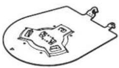 | Main unit mounting screw (with flat washer, spring washer)M3×6 mm (1/4 inches) (1)[AAAAX] |
Drop-prevention wire (1)Drop-prevention wire mounting screw (1)(comes attached to the unit)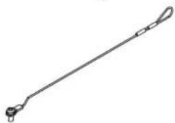 | Bracket mounting screws (bind-head)M4×10 mm (13/32 inches) (4)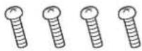 |
Optional accessories
● Wireless remote control AW-RM50G (Size "AA" dry battery x 2, obtained separately)
● Direct ceiling mount bracket WV-Q105A
● Fiber module
- For details on optional accessories, refer to the catalog or consult your local dealer.
■ Shoot under the proper lighting conditions.
To produce pictures with eye-pleasing colors, shoot under the proper lighting conditions.
The pictures may not appear with their proper colors when shooting under fluorescent lights. Select the proper lighting as required.
■ To ensure a stable performance in the long term
Using the unit for prolonged periods in locations where the temperature and humidity levels are high will cause its parts to deteriorate, resulting in a reduction of its service life.
(Recommended temperature: Max. 35 °C (95 °F))
Ensure that a cooling unit or heating unit will not blow any air directly toward the installation location.
■ Do not point the camera at strong lights.
When parts of the MOS sensor are exposed to spotlights or other strong lights, blooming (a phenomenon where the edges of strong lights become blurred) may occur.
Bright subject
Blooming
■ What happens with high-brightness subjects
Flare may occur if an extremely bright light source is pointed at the lens. In a case like this, change the angle or take some other remedial action.
■ When using the automatic functions
- In the [Scene] such as the camera menu, the initial settings on some items has been set to auto, making it impossible for these items to be operated manually. To operate them manually, switch from the auto settings to the manual settings as required.
- When using the ATW (auto tracking white adjustment) function under fluorescent lights, the white balance may vary.
- In some situations, it may be hard to focus at the auto setting. In cases like this, select the manual setting, and focus manually.
■ Zooming and focusing
When the focus is set manually, out-of-focusing may occur during zooming.
After zooming, if necessary, either adjust the focus or set the focus to auto.
When using the focus at the manual setting, proceed with zooming after setting the focus position at the Tele end where the focusing accuracy is higher. (However, if the distance from the unit to the subject is less than 1.5 meters (4.92 ft), the subject may shift out of focus at the Wide end.)
If zooming is performed to the Tele end after having adjusted the focus at the Wide end, out-of-focusing may occur.
■ Operation of the lens when the power is turned on
When the unit's power is turned on, the zoom, focus and iris are adjusted automatically.
The unit comes with the safe mode.
The safe mode is function designed to protect the unit from damage. For details, refer to the Operating Instructions (PDF) "Safe mode" "Concerning the safe mode".
■ Operating temperature range
Avoid using the unit in cold locations where the temperature drops below 0 ^ ( 32 ^ ) or hot locations where the temperature rises above 40 ^ ( 104 ^ ) since these temperatures downgrade the picture quality and adversely affect the internal parts.
■ Concerning the MONI OUT signal
It is anticipated that MONI OUT is used in applications such as for outputting images to be cropped from 4K to HD and for monitoring images.
■ Concerning the HDMI interface standard
This unit has been certified as HDMI-compatible, but on rare occasions images may not be displayed depending on the HDMI device which has been connected to the unit.
Color bars
Color bars are used to adjust the color phase, and the widths and positions of these bars may differ from other models.
■ H.264/H.265 patent pool licensing
This product is licensed based on the AVC Patent Portfolio License, and the license does not extend beyond uses by users, who engage in the acts described below, for their own personal and non-profit applications.
(i) Recording of image information in compliance with the AVC standard (hereafter, "AVC videos")
(ii) Playing of AVC videos recorded by consumers engaging in personal activities or AVC videos acquired from licensed providers
For details, visit MPEG LA, LLC website (http://www.mpegla.com).
■ Concerning PoE++ power supply
The unit complies with the IEEE802.3bt Draft ver.2.0 standard. Use a compatible Ethernet hub and PoE++ injector to use a PoE++ power supply.
For details on Ethernet hubs and PoE++ injectors for which operations have been verified, consult your local dealer.
- The unit does not support software authentication (LLDP communication).
■ Turn off the power before connecting or disconnecting the cables.
This unit is not equipped with a power switch.
Turn off the DC 12 V power supply or PoE++ power supply device before connecting or disconnecting cables.
■ Handle the unit carefully.
Do not drop the unit or subject it to strong impact or vibration. Failure to obey may cause the unit to malfunction.
■ When the unit is not in use
Turn off the unit's power when it is not in use.
When the unit is no longer going to be used, do not leave it lying around, but be absolutely sure to dispose of it properly.
■ Do not touch the optical system parts.
The optical system parts are vital to the operation of the camera. Under no circumstances must they be touched. In the unlikely event that they have become dusty, remove the dust by using a camera blower or by wiping them gently with a lens cleaning paper.
- Do not point the camera directly at the sun or a laser beam no matter whether it is turned on or not.
Taking images of the sun, laser beams, or other brightly lit subjects for prolonged periods of time may damage the CCD.
■ Personal computer used
If the same image is displayed for a prolonged period on a personal computer's monitor, the monitor may be damaged. Use of a screen saver is recommended.
■ Concerning the IP address setting
Do not run the Easy IP Setup Software on a multiple number of personal computers for a single camera and set the IP address at the same time. Otherwise, you will be unable to complete the proper procedure and set the IP address correctly.
■ Do not allow foreign matter to make contact with the rotating parts.
Failure to obey may cause the unit to malfunction.
- Do not get close to the moving parts of the camera head.
Do not put your fingers or body close to the unit while it is in operation. Doing so may result in injury or cause the unit to malfunction. Furthermore, if the unit hits a person or obstacle, during the panning or tilting operation, the unit will enter into the safe mode. For details, refer to the Operating Instructions (PDF) → "Safe mode".
- Keep the unit away from water.
Avoid all direct contact with water. Failure to obey may cause the unit to malfunction.
Maintenance
Turn off the unit's power before proceeding with maintenance. Failure to obey may result in injuries.
Wipe the surfaces using a soft dry cloth. Avoid all contact with benzine, paint thinners and other volatile substances, and avoid using these substances. Otherwise, the casing may become discolored.
■ Do not turn the camera head by hand.
Turning the camera head by hand may cause the unit to malfunction.
■ Use the unit in an environment with minimal moisture and dust.
Avoid using the unit in an environment with high concentration of moisture or dust since these conditions will damage the internal parts.
■ About the lens/pan-tilt head
If the lens, pan-tilt head, and other parts are not operated for a long period of time, the viscosity of the grease applied inside them may increase and operation may become no longer possible. Move the lens and pan/tilt head regularly.
■ About consumables
The following parts are consumables. Replace them using the lifespans as a guide.
The lifespans may vary depending on the operating environment and operating conditions. The lifespans are a guide for when the unit is used at 35 °C ( 95 °F ).
• Cooling fan: Approx. 15000 hours
Contact your dealer regarding replacements.
■ Disposal of the unit
When the unit has reached the end of its service life and is to be disposed of, ask a qualified contractor to dispose of the unit properly in order to protect the environment.
Information on software used with this product
This product includes GNU General Public License (GPL) and GNU Lesser General Public License (LGPL) licensed software, and the customer is entitled to obtain, modify, or redistribute the source code for the software.
This product includes MIT Licensed software.
This product includes BSD Licensed software.
For details on obtaining the source codes, visit the following website.
https://panasonic.biz/cns/sav/
However, do not contact Panasonic for questions regarding obtained source codes.
This unit can be operated by remote control using a wireless remote control (model number: AW-RM50G) purchased separately. Check out the following points before using the wireless remote control.
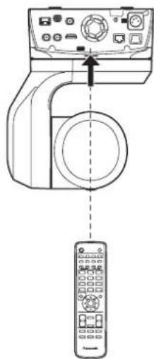
- Point the wireless remote control at the unit's wireless remote control signal light-sensing area (front panel or back panel), and operate it within a range of 10 meters (32.8 ft) from these areas.
- Refer to
on the right.
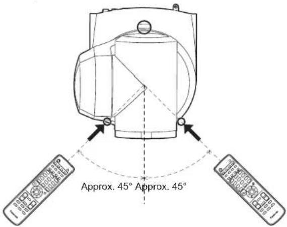
● The signal sensing distance is reduced if the angle at which the wireless remote control signals are sensed is increased.
The light-sensing sensitivity is reduced to about one-half when the wireless remote control is pointed at an angle of 40 degrees from each position in front of a wireless remote control signal light-sensing area (front panel or back panel).
If the remote control is operated from the behind the unit, it may be either difficult or impossible to perform the desired operations.
- If the unit is installed near fluorescent lights, plasma monitors or other such products or if the unit is exposed to sunlight, the effects of the light may make it impossible for the unit to be operated using the wireless remote control.
Be sure to follow the steps below for installation and use.
• Take steps to ensure that the wireless remote control signal light-sensing area will not be exposed to the light from fluorescent lights, plasma monitors or other such products or from the sun.
• Install the unit away from fluorescent lights, plasma monitors and other such products.
- For about 10 minutes even after the batteries have been removed from the wireless remote control, the selection of the operation to be performed (the
When a longer period of time elapses, however, the selection is reset to the status established when the
- The arrows in the figure below show the light-sensing directions in which the wireless remote control signals travel.
Wireless remote control signal light-sensing area (back panel, 1 place)
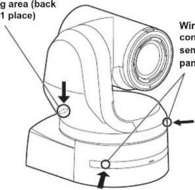
Wireless remote control signal light-sensing area (front panel, 2 places)
- Top view
- Rear panel view
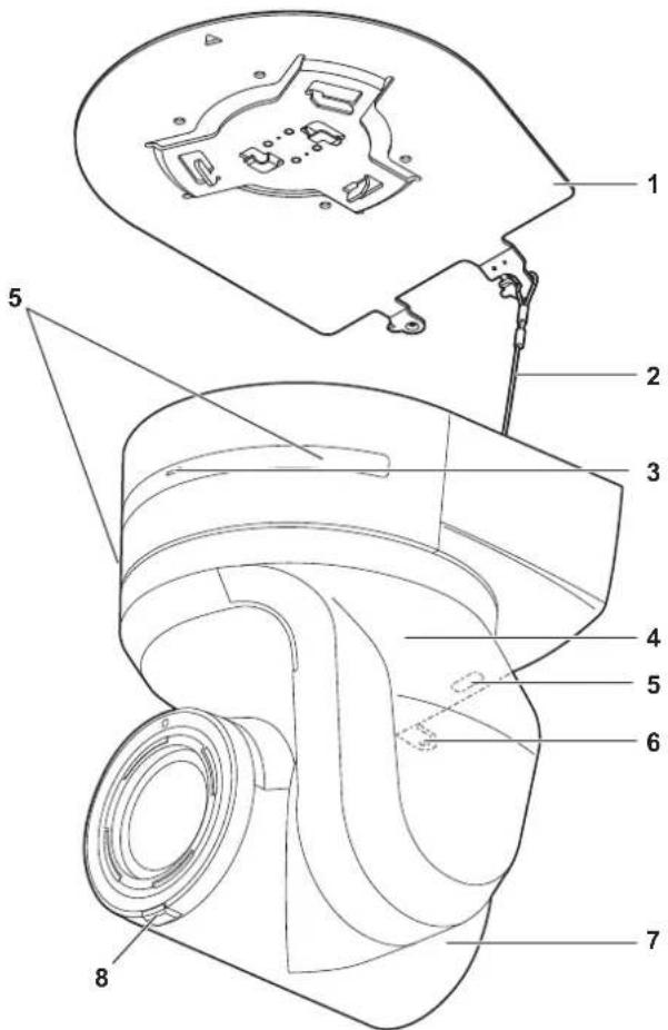
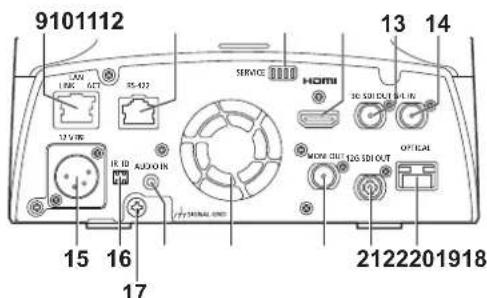
Camera unit
Rear panel
Bottom panel
1. Mount bracket for installation surface (supplied accessory)
Mount this bracket onto the installation surface, and then attach the camera main unit to the bracket.
2. Drop-prevention wire
This wire is screwed down to the bottom panel of the camera main unit. Loop the circle part of the wire around the hook of the mount bracket.
3. Status display lamp
This lights in the following way depending on the status of the unit.
| Orange Light up When the standby status is established | |
| Blink twice When a signal not matched by the remote control ID has been received from the wireless remote control (optional accessory) while the power is on | |
| Green Light up When the power is on | |
| Blink twice When a signal matched by the remote control ID has been received from the wireless remote control (optional accessory) while the power is on | |
| Blinking rapidly When the initialization process is complete | |
| Red Light up When trouble has occurred in the unit | |
| Blinking slowly Firmware being updated | |
| Blinking rapidly When a PoE++ software authentication error has occurred |
4. Tilt head
This rotates in the right and left direction.
5. Wireless remote control signal light-sensing area
The light-sensing area is provided in three places, on the front panel of the camera pedestal and at the top of the rear panel.
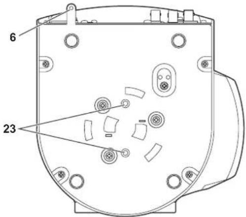
6. Hole for securing the camera pedestal
This hole is provided in the bottom panel of the camera pedestal.
7. Camera head
This rotates in the up and down direction.
8. Tally lamp
This comes on or goes off in response to the control from the controller but only when "On" has been selected as the tally lamp use setting. The tally lamp is red or green.
9. LAN connector for IP control
This LAN connector (RJ-45) is connected when exercising IP control over the unit from an external device. Use a LAN cable (category 5e or better, maximum 100 m (328 ft)) for connection.
10. RS-422 connector
This RS-422 connector (RJ-45) is connected when exercising serial control over the unit from an external device. Use a cable with the following specifications for the connection to this connector. Furthermore, by shorting the R-TALLY signal (2-pin) with the GND (1-pin), it is possible to light the tally lamp (red) in the camera head section of the unit.
- Do not connect PoE cable to the RS-422 port.
- Do not apply a voltage to the R_TALLY_IN signal pin.
- Menu settings enable the output to pin 7 and pin 8 of the red tally and green tally signals received by the unit. Output is by contact output, and normally is "OPEN", then it becomes "MAKE" for output. (Operating Instructions (PDF) → "Camera menu items" → "Output 5/6 screen" → "External Output")
LAN cable*1 (category 5 or above, straight cable), max. 1000 m (3280 ft)
*1 Use of an STP (shielded twisted pair) cable is recommended.
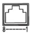
| Pin No. | Signal | Pin No. | Signal |
| 1 GND 5 TXD+ | |||
| 2 R_TALLY_IN 6 RXD+ | |||
| 3 RXD-7 | OPTION_OUT1 | ||
| 4 TXD-8 | OPTION_OUT2 | ||
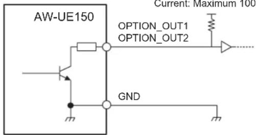
■ Example OPTION\_OUT1, OPTION\_OUT2 connector connections
Voltage: Maximum DC12 V
Current: Maximum 100 mA
11. Service switches
Perform switch settings before turning the unit on.
| Function Factory settings | ||
| SW1 SW | Switches for initialization(Refer to the explanations in “Initialization 1” and “Initialization 2”) | OFF |
| SW2 | Always leave at OFF (used for factory adjustments) | OFF |
| SW3 OFF | ||
| SW4 OFF | ||
Initialization 1
- Reset the user authentication settings and host authentication settings for network connection. (This will delete all the registered user information (IDs/passwords) and host information (IP addresses).)
- With the IR ID switches and service switches set as shown below, turn on the power of the unit.
- When initialization is complete, the status display lamp on the front of the unit blinks green. Restart the unit to confirm the initialization.
Initialization 2
- The unit is reset to the state it was in at the time of purchase. (All camera menu setting values and network setting values are reset.)
- With the IR ID switches and service switches set as shown below, turn on the power of the unit.
- When initialization is complete, the status display lamp on the front of the unit blinks green. Restart the unit to confirm the initialization.
12. HDMI connector
This is the HDMI video output connector.
13. 3G SDI OUT connector <3G SDI OUT>
This is the 3G SDI video signal output connector.
14. G/L IN connector
This is the external sync signal input connector.
This unit supports BBS (Black Burst Sync) and tri-level synchronization.
Supply to this connector the signals that correspond to the video signal format which has been set.
Frequency: 59.94 Hz, 29.97 Hz
| Format | External sync signal input format | ||
| Tri-level sync BBS | |||
| 2160/59.94p 1080/59.94p720/59.94p | 1080/29.97p1080/59.94i1080/29.97PsF | 480/59.94i | |
| 2160/29.97p — | |||
| 1080/59.94p 1080/59.94p720/59.94p | |||
| 1080/59.94i — | |||
| 1080/29.97p — | |||
| 1080/23.98PsF — | |||
| 1080/23.98p over 59.94i | — | ||
| 720/59.94p 1080/59.94p720/59.94p | |||
Frequency: 50 Hz, 25 Hz
| Format | External sync signal input format | ||
| Tri-level sync BBS | |||
| 2160/50p 1080/50p | 720/50p | 1080/25p1080/50i1080/25PsF | 576/50i |
| 2160/25p — | |||
| 1080/50p 1080/50p | 720/50p | ||
| 1080/50i — | |||
| 1080/25p — | |||
| 1080/25PsF — | |||
| 720/50p 1080/50p | 720/50p | ||
Frequency: 24 Hz
| Format | External sync signal input format |
| Tri-level sync | |
| 2160/24p 1080/24p | 1080/24PsF |
| 1080/24p |
Frequency: 23.98 Hz
| Format | External sync signal input format |
| Tri-level sync | |
| 2160/23.98p 1080/23.98p | 1080/23.98PsF |
| 1080/23.98p | |
| 1080/23.98PsF |
15. DC IN connector <12 V-IN> (XLR connector)
Input 12 V DC.
- Use a DC cable with the following lengths.
For 12 V input: Max. 3 m (9.84 ft) (when using an AWG16 cable)
External DC power supply
Connect after making sure that the output voltage of the external DC power supply is compatible with the rated voltage of the camera.
Select an output amperage for the external DC power supply with a margin above the total amperage of the connected devices.
The total amperage of connected devices can be calculated with the following formula.
Total power consumption ÷ voltage
When the power of the camera is turned on, inrush current is generated. Insufficient power supply when turning on the power may cause a malfunction. We recommend that you use an external DC power supply that can assure double the capacity of the total power consumption of the camera and connected devices that are turned on by interlock when the power of the camera is turned on (such as lenses, wireless microphone receivers).
| Make sure of the pin alignment of the DC output terminal of the external DC power supply and the camera DC IN connector, and connect the polarity correctly.If the +12 V power supply is mistakenly connected to the GND terminal, it may cause fire or malfunction. |
| 12 V | ||
| 1 | GND | |
| 2 | — | |
| 3 | — | |
| 4 | +12 V | |
| HA16RA-4P (77)Hirose Electric Co. | ||
16. IR ID switches
| CAM1 | CAM2 | CAM3 | CAM4 |
 | IR ID | IR ID |
These are used to select the ID of the wireless remote control (optional accessory). ( page 56)
The IR ID switch settings "CAM1" to "CAM4" correspond to the
17. Ground connector
Connects to the ground connector on a wall outlet, ground bar, etc. for grounding. ( page 24)
18. AUDIO IN connector
Inputs external audio (microphone, line).
19. Ventilation holes
Blocking the ventilation holes may cause a malfunction. Make sure there is sufficient space around the ventilation holes.
20. MONITOR OUT connector
This is an SDI video signal output connector. Use it in applications such as displaying the crop position when cropping from 4K to HD and for monitoring images.
21.12G SDI OUT connector <12G SDI OUT>
This is a 12G-SDI video signal output connector.
22. Optical connector
This is the connector for the SFP+ optical fiber module. By connecting the optional fiber module, it is possible to output signals converted to optical signals from SDI signals. Select the fiber module that suits the signal band*1 for each format.
^*1 • 4K (59.94p, 50p): 12G
- 4K (other than 59.94p, 50p): 6G
• HD (59.94p, 50p): 3G
• HD (other than 59.94p, 50p): 1.5G
- This unit does not support input by optical signals.
23. Tripod screw holes
(Screw: 1/4-20 UNC, ISO 1222 [6.35 mm (1/4 inches)])
Use these screw holes when securing the unit to a tripod, etc.
Output conditions for each video format
| Frequency System Format HDMI 12 | G SDI OUT OPTICAL 3G SDI OUT MONI OUT | ||||
| 59.94Hz | 2160/59.94p 2160/59.94p 2160/59.94p 2160/59.94p 2160/59.94p 2160/59.94p 2160/59.94p 2160/59.94p 2160/59.94p 216 | 59.94p | 1080/59.94p1080/59.94i | 1080/59.94i | |
| 2160/29.97p 2160/29.97p 2160/29.97p 2160/29.97p 2160/29.97p 2160/29.97p 2160/29.97p 2160/29.97p 2160/29.97p 216 | 29.97p | 1080/29.97p1080/29.97PsF | 1080/29.97p1080/29.97PsF | ||
| 1080/59.94p 1080/59.94p 1080/59.94p 1080/59.94p 1080/59.94p 1080/59.94p 1080/59.94p 1080/59.94p 1080/59.94p 108 | 59.94p | 1080/59.94p1080/59.94i | 1080/59.94i | ||
| 1080/59.94i 1080/59.94i 1080/59.94i 1080/59.94i 1080/59.94i 1080/59.94i 1080/59.94i 1080/59.94i 108 | 94i 1080/59.94i 1080/59.94i | ||||
| 1080/29.97p 1080/29.97p 1080/29.97p 1080/29.97p 1080/29.97p 1080/29.97p 1080/29.97p 1080/29.97p 1080/29.97p 108 | 29.97p 1080/29.97p 1080/29.97p 1080/29.97p | ||||
| 1080/29.97PsF 1080/29.97p 1080/29.97PsF 1080/29.97PsF 1080/29.97PsF 1080/29.97PsF 1080/29.97PsF 1080/29.97PsF 1080/29.97PsF 1080/29.97PsF 1080/29,99 | 1080/29.97PsF 1080/29.97PsF 1080/29.97PsF 1080/29.97PsF 1080/29.97PsF 1080/29.97PsF 1080/29.97PsF 1080/29. | ||||
| 1080/23.98p over59.94i | 1080/23.98p over59.94p | 1080/23.98p over59.94i | 1080/23.98p over59.94i | 1080/23.98p over59.94i | |
| 720/59.94p 720/59.94p 720/59.94p 720/59.94p 720/59.94p 720/59.94p 720/59.94p 720/59.94p 720/59.94p 720/59.94p 1080/50p 1080/50p 1080/50p 1080/50p 1080/50p 1080/50p 1080/50p 1080/50p 1080/50p 1080/50p 1080/50p 1080/50P | |||||
| 50Hz | 2160/50p 2160/50p 2160/50p 2160/50p 2160/50p 2160/50p 2160/50p 2160/50p 2160/50p 2160/50p 2160/50p 2160/50p 1080/50p 1080/50p 1080/50p 1080/50p 1080/50p 1080/50p 1080/50p 1080/50p 1080/50p 1080/50p 108 | 1080/50p1080/50i | 1080/50p1080/50i | 1080/50i | |
| 2160/25p 2160/25p 2160/25p 2160/25p 2160/25p 2160/25p 2160/25p 2160/25p 2160/25p 2160/25p 2160/25p 2160/25p 1080/50p 1080/50p 1080/50p 1080/50p 1080/50p 1080/50p 1080/50p 1080/50p 1080/50p 1080/50p 108 | 108 | 1080/25p1080/25PsF | 1080/25p1080/25PsF | ||
| 1080/50p 1080/50p 1080/50p 1080/50p 1080/50p 1080/50p 1080/50p 108 | 1080/50p1080/50i | 1080/50p1080/5Oi | |||
| 1080/50p 1080/50p 1080/50p 1080/50p 1080/50p 1080/50p 108 | 1080/50i | ||||
| 1080/25p 1080/25p 1080/25p 1080/25p 1080/25p 1080/25p 108 | 25p 1080/25p | ||||
| 1080/25PsF 1080/25p 1080/25PsF 1080/25PsF 1080/25PsF 1080/25PsF 108 | 1080/25PsF 1080/25PsF 1080/25PsF 108 | 1080/25PsF | |||
| 720/50p 720/50p 720/50p 720/50p 720/50p 720/50p 720/50p 720/50p 720/50p 720/50p 720/50p 720/50p 720/50p 720 | 20/50p | ||||
| 24Hz | 2160/24p 2160/24p 2160/24p 2160/24p 2160/24p 2160/24p 2160/24p 2160/24p 2160/24p 2160/24p 2160/24p 2160/24p 108 | 24p 1080/24p | |||
| 1080/24p 1080/24p 1080/24p 1080/24p 1080/24p 1080/24p 1080/24p 108 | 24p 1080/24p | ||||
| 23.98Hz | 2160/23.98p 2160/23.98p 2160/23.98p 2160/23.98p 2160/23.98p 2160/23.98p 2160/23.98p 2160/23.98p 216 | 23.98p | 1080/23.98p1080/23.98PsF | 1080/23.98p1080/23.98PsF | |
| 1080/23.98p 1080/23.98p 1080/23.98p 1080/23.98p 1080/23.98p 108 | 23.98p 1080/23.98p 1080/23.98p 108 | 23.98p | |||
| 1080/23.98PsF 1080/23.98p 1080/23.98PsF 108 | 1080/23.98PsF 1080/23.98PsF 108 | 1080/23.98PsF 1080/23.98PsF | |||
■ IP video transmission output (multi-channel display)
- When "Streaming mode" is set to "H.265 (UHD)"
| Settings H.265 H.264(1) H.264(2) | 3840×2160 | H.264(3) H.264(4) JPEG(1) JPEG(2) JPEG(3) | JPEG(1) JPEG(2) JPEG(3) | |||||
| Resolution | 1920×10801280×720640×360 640×360 640×360320×180 320×180 320×180 | |||||||
| Frame rate | System frequency 59.94Hz | 30fps — — | —— | 30fps 30fps 30fps15fps 15fps 15fps5fps 5fps 5fps1fps 1fps 1fps | ||||
| System frequency 50Hz | 25fps — — | —— | 25fps 25fps 25fps12.5fps 12.5fps 12.5fps5fps 5fps 5fps1fps 1fps 1fps | |||||
| System frequency 29.97Hz | 30fps — — | —— | 30fps 30fps 30fps15fps 15fps 15fps5fps 5fps 5fps1fps 1fps 1fps | |||||
| System frequency 25Hz | 25fps — — | —— | 25fps 25fps 25fps12.5fps 12.5fps 12.5fps5fps 5fps 5fps1fps 1fps 1fps | |||||
| System frequency 24/23.98Hz | 24fps — — | —— | 24fps 24fps 24fps12fps 12fps 12fps4fps 4fps 4fps1fps 1fps 1fps | |||||
• The H.265 (UHD) transmission mode (Transmission priority) cannot be selected.
- When "Streaming mode" is set to "H.264"
| Settings H.265 H.264(1) H.264(2) | H.264(3) H.264(4) JPEG(1) JPEG(2) JPEG(3) | ||||||||
| Resolution — | 1920×1080 1920×1080 1920×10801280×720 1280×720 1280×720 1280×720640×360 640×360 640×360 640×360 640×360 640×360320×180 320×180 320×180 320×180 320×180 | ||||||||
| Frame rate | System frequency 59.94Hz | — | 60fps 60fps30fps 30fps 30fps 30fps 30fps 30fps 15fps 15fps 15fps 15fps 15fps 15fps 5fps 5fps 5fps 5fps 5fps 5fps | 1fps 1fps 1fps | |||||
| System frequency 50Hz | — | 50fps 50fps25fps 25fps 25fps 25fps 25fps 12.5fps 12.5fps 12.5fps 12.5fps 12.5fps 12.5fps 5fps 5fps 5fps 5fps 5fps 5fps | 1fps 1fps 1fps | ||||||
| System frequency 29.97Hz | — | 30fps 30fps 30fps 30fps 30fps 30fps 30fps 15fps 15fps 15fps 15fps 15fps 15fps 5fps 5fps 5fps 5fps 5fps 5fps | 1fps 1fps 1fps | ||||||
| System frequency 25Hz | — | 25fps 25fps 25fps 25fps 25fps 25fps 25fps 12.5fps 12.5fps 12.5fps 12.5fps 12.5fps 12.5fps 5fps 5fps 5fps 5fps 5fps 5fps | 1fps 1fps 1fps | ||||||
| System frequency 24/23.98Hz | — | 24fps 24fps | — | — | 24fps 24fps 24fps12fps 12fps 12fps4fps 4fps 4fps1fps 1fps 1fps | ||||
- The available options for the H.264 transmission mode (Transmission priority) are limited to 30fps or lower (excluding 24fps).
- When the system frequency is 24/23.98Hz, the resolution for H.264(1) and H.264(2) is limited to 1920 × 1080 .
- When "Streaming mode" is set to "H.264 (UHD)"
| Settings H.265 H.264(1) H.264(2) | H.264(3) H.264(4) JPEG(1) JPEG(2) JPEG(3) | |||||||
| Resolution — | 3840×2160 | ——— | 1920×10801280×720640×360 640×360 640×360320×180 320×180 320×180 | |||||
| Frame rate | System frequency 59.94Hz | — | 60fps30fps 30fps | 30fps 30fps | 15fps 15fps 15fps5fps 5fps 5fps1fps 1fps 1fps | |||
| System frequency 50Hz | — | 50fps25fps 25fps | 25fps 25fps | 12.5fps 12.5fps 12.5fps5fps 5fps 5fps1fps 1fps 1fps | ||||
| System frequency 29.97Hz | — | 30fps | ——— | 30fps 30fps 30fps15fps 15fps 15fps5fps 5fps 5fps1fps 1fps 1fps | ||||
| System frequency 25Hz | — | 25fps | ——— | 25fps 25fps 25fps12.5fps 12.5fps 12.5fps5fps 5fps 5fps1fps 1fps 1fps | ||||
| System frequency 24/23.98Hz | — | 24fps | ——— | 24fps 24fps 24fps12fps 12fps 12fps4fps 4fps 4fps1fps 1fps 1fps | ||||
• The H.264 (UHD) transmission mode (Transmission priority) cannot be selected.
- When "Streaming mode" is set to "JPEG (UHD)"
| Settings H.265 H.264(1) H.264(2) | H.264(3) H.264(4) JPEG(1) JPEG(2) JPEG(3) | ||||||||
| Resolution — | 1920×1080 1920×10801280×720 1280×720 1280×720 640×360 640×360 640×360 320×180 320×180 320×180 | 3840×2160 | — | — | |||||
| Frame rate | System frequency 59.94Hz | — | 60fps 60fps30fps 30fps 30fps 30fps15fps 15fps 15fps 15fps5fps 5fps 5fps 5fps 5fps | 1fps | — | — | |||
| System frequency 50Hz | — | 50fps 50fps25fps 25fps 25fps 25fps12.5fps 12.5fps 12.5fps 12.5fps5fps 5fps 5fps 5fps 5fps | 1fps | — | — | ||||
| System frequency 29.97Hz | — | 30fps 30fps 30fps 30fps15fps 15fps 15fps 15fps5fps 5fps 5fps 5fps 5fps | 1fps | — | — | ||||
| System frequency 25Hz | — | 25fps 25fps 25fps 25fps12.5fps 12.5fps 12.5fps 12.5fps5fps 5fps 5fps 5fps 5fps | 1fps | — | — | ||||
| System frequency 24/23.98Hz | — | 24fps 24fps | — — — — | 4fps1fps | |||||
• The available options for the H.264 transmission mode (Transmission priority) are limited to 30fps or lower (excluding 24fps).
- When the system frequency is 24/23.98Hz, the resolution for H.264(1) and H.264(2) is limited to 1920 × 1080 .
- When "Streaming mode" is set to "RTMP"
| Settings H.265 H.264(1) H.264(2) | H.264(3) H.264(4) JPEG(1) JPEG(2) JPEG(3) | ||||||||
| Resolution — | 1920×10801280×720 1280×720——— | 1920×1080640×360 640×360 640×360 320×180 320×180 | |||||||
| Frame rate | System frequency 59.94Hz | — | 60fps30fps 30fps 15fps 15fps 5fps 5fps 5fps 5fps | 1fps 1fps 1fps | |||||
| System frequency 50Hz | — | 50fps25fps 25fps 12.5fps 12.5fps 5fps 5fps 5fps 5fps 5fps | 1fps 1fps 1fps | ||||||
| System frequency 29.97Hz | — | 30fps15fps 15fps 5fps 5fps 5fps 5fps 5fps 5fps 5fps 5fps 5fps 5fps 5fps 5fps 5fps 5fps 5fps 5fps 5fps 5fps 5fps 5fps 5fps 5fps 5fps 5fps 5fps 5fps 5fps 5fps 5fps 5fps 5fps 5fps 5fps 29.97Hz | 30fps 30fps 30fps1fps 1fps 1fps | ||||||
| System frequency 25Hz | — | 25fps12.5fps 12.5fps 5fps 5fps 5fps 5fps 5fps 5fps 5fps 5fps 5fps 5fps 5fps 5fps 5fps 5fps 5fps 5fps 5fps 5fps 5fps 5fps 5fps 5fps 5fps 5fps 5fps 5fps 5fps 5fps 5fps 5fps 5fps 5fps 1fps 1fps 1fps | 25fps 25fps 25fps1fps 1fps 1fps | ||||||
| System frequency 24/23.98Hz | — | 24fps | 24fps 24fps 24fps12fps 12fps 12fps4fps 4fps 4fps1fps 1fps 1fps | ||||||
- The available options for the H.264 transmission mode (Transmission priority) are limited to 30fps or lower (excluding 24fps).
-
When the system frequency is 24/23.98Hz, the resolution for H.264(1) and H.264(2) is limited to 1920 × 1080 .
-
When "Streaming mode" is set to "NDI|HX"
| Settings NDI|HX JPEG(1) | |||
| Resolution | 1920×10801280×720 1280×720640×360320×180 | ||
| Frame rate | System frequency59.94Hz | 60fps30fps 30fps15fps 15fps5fps 5fps | 1fps |
| System frequency50Hz | 50fps25fps 25fps12.5fps 12.5fps5fps 5fps | 1fps | |
| System frequency29.97Hz | 30fps 30fps15fps 15fps5fps 5fps | 1fps | |
| System frequency25Hz | 25fps 25fps12.5fps 12.5fps5fps 5fps | 1fps | |
- It is not possible to select NDI|HX mode when the system frequency is 24/23.98 Hz.
- The transmission mode (Transmission priority) cannot be selected.
Wireless remote control: AW-RM50G (not supplied)
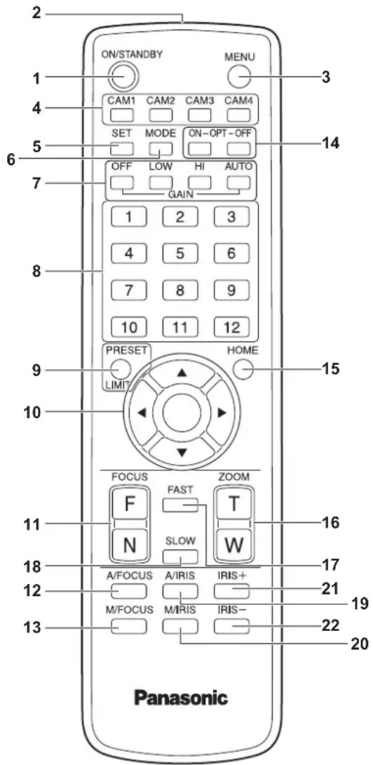
1. ON/STANDBY button
Each time this is pressed for 2 seconds, operation switches between turning on the unit's power and establishing the standby status.
2. Signal transmission window
3. MENU button
Each time this is pressed for 2 seconds, operation switches between displaying the unit's camera menu and exiting the camera menu.
When it is pressed quickly (for less than 2 seconds) while a camera menu is displayed, the setting change is canceled.
Furthermore, the pan and tilt movement range limits (limiters) are set and released by operating the

- Operating Instructions
- Excerpted Version
- 4K Integrated Camera
- AW-UE150WP AW-UE150KP AW-UE150WE AW-UE150KE
- HDMI™
- ■ Trademarks and registered trademarks
- ■ About copyright and licence
- Abbreviations
- ■ Illustrations and screen displays featured in the manual
- Installation Instructions
- WARNING:
- CAUTION:
- To installation personnel
- ■ Ensure that the installation work complies with the technical standards governing electrical equipment.
- ■ This unit is for indoor use only.
- ■ Use the unit with an installation where the unit is suspended from an overhead surface or with a stand-alone installation.
- Recommended clamping torque
- ■ Concerning the installation location
- - Do not install or use the unit in the following kinds of locations.
- ■ What to avoid to ensure that the unit will perform stably over a prolonged period
- - Be absolutely sure to use the supplied brackets and screws to install the camera.
- ■ Before installation, always disconnect the DC connector
- ■ Tightening up the mounting screws
- When the unit is no longer going to be used, do not leave it lying around, but be absolutely sure to dispose of it properly.
- - When installing, transferring or disposing of the unit, be absolutely sure to hold it by its pedestal area.
- - Do not attach a filter, hood, extender or other parts to the unit.
- ■ Install the external DC power supply near the main power outlet, and position it in such a way that its power plug can be plugged into and unplugged from the outlet easily.
- Power switch
- Grounding
- If there is a possibility of noise interference
- ■ Radio signal interference
- ■ When connecting the cables, ensure that the connector areas will not be subject to any load.
- ■ Allowing the generated heat to escape
- ■ PoE++ power supplies
- Network settings
- IR ID switch settings
- Service switch settings
- Initialization 1
- Initialization 2
- Check the mounting space.
- Mount the mount bracket onto the installation surface.
- Attach the drop-prevention wire.
- Mount the unit.
- Check the mounting.
- Connect the rear panel connectors.
- When using the WV-Q105A (optional accessory)
- Stand-alone installation (when the mount bracket is going to be used)
- Stand-alone installation (when the mount bracket is not going to be used)
- When installing the unit on a desktop
- When mounting the unit on a tripod
- Connecting an NDI|HX compatible switcher
- Connections with a controller (AW-RP150)
- ■ Example of connection for the function for cropping 4K images to HD images
- System example 2 (IP control)
- System example 3 (IP image transmission, PoE++)
- Note on grounding
- FCC NOTICE (USA)
- Declaration of Conformity
- FCC Warning:
- NOTIFICATION (Canada)
- EMC NOTICE FOR THE PURCHASER/USER OF THE APPARATUS
- Pre-requisite conditions to achieving compliance with the above standards
- Performance level
- Disposal of Old Equipment
- Only for European Union and countries with recycling systems
- AVERTISSEMENT:
- IMPORTANT
- Disclaimer of warranty
- Network security
- Notes on user authentication
- Usage restrictions
- ■ Multi-format support
- [4K format]
- [HD format]
- ■ 1-type 4K MOS sensor and high-performance 20x zoom lens featured
- ■ Easy operation of unit enabled by its integration with a high-performance pan-tilt head unit
- Built-in night mode
- ■ IP image output functions
- - High degree of compatibility with Panasonic's currently available controllers, enabling a flexible system to be put together
- ■ Easy construction of systems thanks to integrated design used for pan-tilt head, camera and lens
- ■ Use of easy-to-operate wireless remote control (optional accessory) is possible
- ■ Flexible camera layout enabled by simple connection and installation
- ■ While including a larger 4K lens and pan/tilt mechanism, the unit still has the same installation footprint as previous models.
- ■ Easy connections and settings courtesy of IP control
- ■ PoE++ \*3 eliminates need for camera power configurations
- Optional accessories
- ■ Shoot under the proper lighting conditions.
- ■ To ensure a stable performance in the long term
- ■ Do not point the camera at strong lights.
- ■ What happens with high-brightness subjects
- ■ When using the automatic functions
- ■ Zooming and focusing
- ■ Operation of the lens when the power is turned on
- The unit comes with the safe mode.
- ■ Operating temperature range
- ■ Concerning the MONI OUT signal
- ■ Concerning the HDMI interface standard
- Color bars
- ■ H.264/H.265 patent pool licensing
- ■ Concerning PoE++ power supply
- ■ Turn off the power before connecting or disconnecting the cables.
- ■ Handle the unit carefully.
- ■ When the unit is not in use
- ■ Do not touch the optical system parts.
- - Do not point the camera directly at the sun or a laser beam no matter whether it is turned on or not.
- ■ Personal computer used
- ■ Concerning the IP address setting
- ■ Do not allow foreign matter to make contact with the rotating parts.
- - Do not get close to the moving parts of the camera head.
- - Keep the unit away from water.
- Maintenance
- ■ Do not turn the camera head by hand.
- ■ Use the unit in an environment with minimal moisture and dust.
- ■ About the lens/pan-tilt head
- ■ About consumables
- ■ Disposal of the unit
- Information on software used with this product
- Camera unit
- Mount bracket for installation surface (supplied accessory)
- Drop-prevention wire
- Status display lamp
- Tilt head
- Wireless remote control signal light-sensing area
- Hole for securing the camera pedestal
- Camera head
- Tally lamp
- LAN connector for IP control
- RS-422 connector
- ■ Example OPTION\_OUT1, OPTION\_OUT2 connector connections
- Service switches
- HDMI connector
- 3G SDI OUT connector <3G SDI OUT>
- G/L IN connector
- DC IN connector <12 V-IN> (XLR connector)
- External DC power supply
- Total power consumption ÷ voltage
- IR ID switches
- Ground connector
- AUDIO IN connector
- Ventilation holes
- MONITOR OUT connector
- 21.12G SDI OUT connector <12G SDI OUT>
- Optical connector
- Tripod screw holes
- ■ IP video transmission output (multi-channel display)
- Wireless remote control: AW-RM50G (not supplied)
- ON/STANDBY button
- Signal transmission window
- MENU button
- CAM1 to CAM4 buttons
- SET button
- MODE button
- GAIN button
- Preset memory call buttons <1> to <12>
- PRESET/LIMIT button
- Pan-tilt buttons and menu operation buttons
- <▲> <▼> <◀> ◀> <○>
- FOCUS button
- A/FOCUS button
- M/FOCUS button
- OPT button
- HOME button
- ZOOM button
- FAST button
- SLOW button
- A/IRIS button
- M/IRIS button
- IRIS + buuton
- IRIS - button
- Setting the remote control IDs
- Setting procedure
- Use the Easy IP Setup Software to establish the unit's settings
- Click the [Search] button.
- Click the MAC address/IPv4 address of the camera to be set, and click the [Network Settings] button.
- Input the network items, and click the [Save] button.
- Setting the initial account
- Set the initial account.
- Completing registration of the initial account
- Installing the plug-in viewer software
- Turning the power on
- When performing operations from a wireless remote control
- Set all the power switches of the units and devices connected in the system to ON.
- Press one of the to buttons on the wireless remote control to select the unit.
- Press the button on the wireless remote control for about 2 seconds.
- If a multiple number of units are going to be used, repeat steps 2 and 3 as required.
- When performing operations from a controller
- Turning the power off
- Web screen
- For Windows:
- GENERAL
- Numerics
- A
- C
- D
- E
- G
- H
- |
- L
- M
- N
- 0
- P
- R
- s
- T
- V
- W
Brand : PANASONIC
Model : AW-UE150KP
Category : Security Camera