
VPL-FHZ131 - Vidéo-projecteur SONY - Free user manual and instructions
Find the device manual for free VPL-FHZ131 SONY in PDF.

| Product Type | Video Projector |
| Model | VPL-FHZ131 (also VPL-FHZ101L/FHZ91L) |
| Display System | 3 LCD, 1.0" panels, 16:10 aspect ratio, 6,912,000 pixels (1920 x 1200 x 3) |
| Light Source | Laser Diode |
| Light Output | 13,000 lm (VPL-FHZ131L, Standard mode) |
| Projected Image Size | 40" to 600" (1.02 m to 15.24 m) |
| Dimensions (W x H x D) | 544 x 225 x 572 mm (21 13/32" x 8 27/32" x 22 17/32") with protrusions; 544 x 205 x 564 mm without |
| Weight | Approx. 27 kg (58 lb) |
| Power Requirements | AC 100 V to 240 V, 10.8 A to 4.4 A, 50/60 Hz |
| Power Consumption (Max) | 1,076 W (100-120 V) / 1,033 W (220-240 V) |
| Standby Power Consumption | 0.50 W (Low mode); up to 26.6 W (Networked Standby) |
| Input Terminals | RGB/YPbPr (5BNC), RGB (Mini D-sub 15-pin), DVI-D, HDMI, HDBaseT (RJ45), LAN, RS-232C, USB |
| Output Terminal | Monitor output (Mini D-sub 15-pin) |
| Network Features | Web browser control, e-mail reports, PJLink, SNMP, Crestron RoomView |
| Keystone Correction | Vertical and horizontal keystone, warp correction, edge blending |
| Lens Shift | Electric lens shift (vertical/horizontal) with specific lens |
| Maintenance | Cleanable air filter; filter cleaning reminder |
| Safety Features | Security lock (password), control key lock, antitheft bar/lock |
| Optional Accessories | Projection lenses (VPLL-4008, Z4111, etc.), 3G-SDI adaptor (BKM-PJ20) |
| Operating Temperature | 0°C to 45°C (32°F to 113°F) |
Frequently Asked Questions - VPL-FHZ131 SONY
User questions about VPL-FHZ131 SONY
0 question about this device. Answer the ones you know or ask your own.
Ask a new question about this device
Download the instructions for your Vidéo-projecteur in PDF format for free! Find your manual VPL-FHZ131 - SONY and take your electronic device back in hand. On this page are published all the documents necessary for the use of your device. VPL-FHZ131 by SONY.
USER MANUAL VPL-FHZ131 SONY
Operating Instructions
Before operating the unit, please read this manual and supplied Quick Reference Manual thoroughly and retain them for future reference.
VPL-FHZ131L/FHZ101L/FHZ91L
Not all models are available in all countries and area. Please check with your local Sony Authorized Dealer.
Table of Contents
Location of Controls
Main Unit 4
Terminals 5
Remote Commander and Control Panel ...... 6
Connections and Preparations
Connecting the Projector 8
Connecting to a Computer 8
Connecting to a Video Device 9
Connecting to an External Monitor .....10
Connecting to a Network Equipment .....11
Connecting to a HDBaseT™ Device ......11
Attaching the Projection Lens 13
Removing the Projection Lens 13
Attaching the Terminal Cover ....14
Removing the Terminal Cover ....14
Installing the Optional Adaptor 15
Projecting/Adjusting an Image
Projecting an Image ....16
Turning Off the Power 16
Adjusting the Projected Image 17
Focusing the image (Focus) 17
Adjusting the image size (Zoom) 17
Adjusting the position of the image (Lens shift) 17
Correcting for Trapezoidal Distortion of the Projected Image (Keystone Adjustment) 18
Correcting Image Twist (Warp Correction Feature) 19
Blending Projections from Multiple Projectors on a Screen 20
Using Convenient Functions 21
Selecting the Stored Picture Settings (Picture Position Function) (Specified Lens Only) 21
Enlarging a Part of the Image (Digital Zoom Function) 22
Projecting Images with Two Pictures Simultaneously (Two-Picture Display Function) 22
Adjustments and Settings Using a Menu
Using a Menu ....23
Projection Setting Menu 24
The Screen Menu 27
The Function Menu 29
The Operation Menu 30
The Connection/Power Menu 31
The Installation Menu ....33
The Information Menu 36
Network Features
Using Network Features ....37
Displaying the Control Window of the Projector with a Web Browser ....37
Confirming the Settings for the Projector .... 38
Operating the Projector from a Computer 38
Using the e-mail Report Function ...... 38
Configure the Network Settings 40
Setting the Control Protocol of the Projector ....41
About the HTML Viewer Function 43
Using the Software Update Function ..... 45
Error Handling
Indicators 46
Messages List 48
Troubleshooting 49
Others
Cleaning the Air Filter 51
Updating the Software 52
Updating the Software via the USB Memory ....52
Updating the Software via the Network .....52
Specifications ....53
Pin assignment 56
Acceptable Input Signals ....57
Projection Distance and Lens Shift Range ..... 58
Dimensions 61
About Trademarks 63
NOTICES AND LICENSES FOR SOFTWARE USED IN
THIS PRODUCT 63
Main Unit
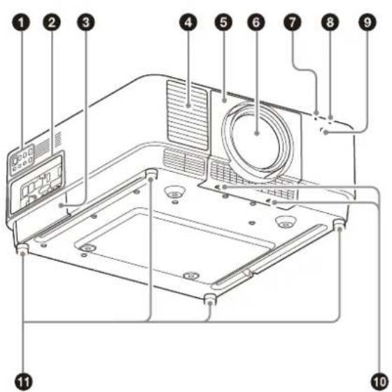
① Control panel (page 6)
② Terminals (page 5)
③ Optional adaptor slot (page 15)
An optional adaptor (not supplied) can be attached.
4 Ventilation holes (intake)
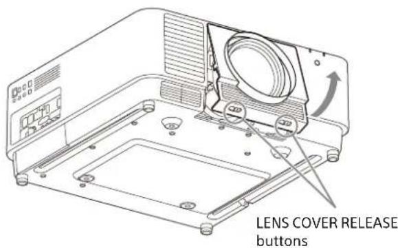
⑤ Lens cover (page 13)
⑥ Lens (not supplied) (page 13)
7 ON/STANDBY indicator (page 46)
8 WARNING indicator (page 46)
9 Remote control receiver
Located at the front and rear of the projector.
10 LENS COVER RELEASE buttons (page 13)
⑪ Adjustable feet (page 17)
12 Filter cover (page 51)
13 Ventilation holes (exhaust)
14 Antitheft bar
Connects to a commercially available antitheft chain or wire.
15 Antitheft lock
Connects to an optional antitheft cable manufactured by Kensington.
For details, visit the Kensington's website. http://www.kensington.com/
Caution
Do not place anything near the ventilation holes. The temperature may rise inside the unit, leading to a possible malfunction or fire. Do not place your hand or easily deformable objects near the ventilation holes (exhaust) and its vicinity. Doing so may cause burns or deformation.
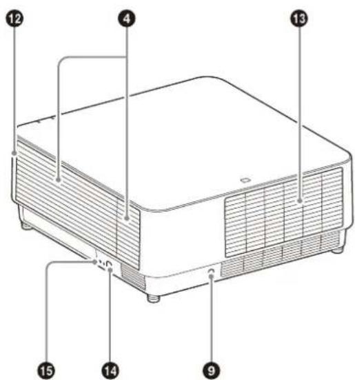
Terminals
① INPUT A
Video: RGB/YP B PR input terminal (RGB HD VD/YP B PR)
② INPUT B
Video: RGB input terminal (RGB)
③ INPUT C
Video: DVI-D input terminal (DVI-D)
4 INPUT D
Video: HDMI input terminal (HDMI)
5 INPUT E
HDBaseT terminal
6 INPUT F
For details on available optional adaptors, see "Optional accessories" (page 54).
⑦ LAN terminal (page 11)
Available as INPUT G when using for the HTML viewer function (page 43).
8 OUTPUT
Video: RGB/YP B PR output terminal (RGB/YP B PR) This terminal outputs projected images. The images are output when a computer signal is input from the RGB input terminal (INPUT A, INPUT B) or a video signal is input from the YP _B PR input terminal (INPUT A).
9 USB port
For the HTML viewer and updating the software (page 43, 45). Available as INPUT G when using for the HTML viewer function (page 43).
Note
USB hub is not available on the USB port.
10 RS-232C terminal
RS-232C compatible control terminal
⑪ AC IN ( ) socket
Connects the supplied AC power cord.
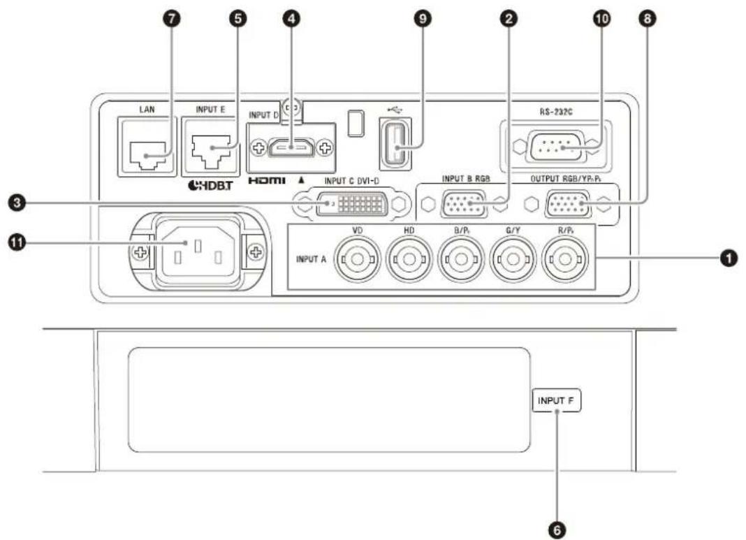
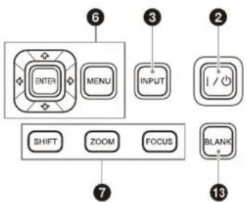
Remote Commander and Control Panel
Remote Commander
Control Panel
① Infrared transmitter
② I (On) key/⏻ (Standby) key
Turns on the projector or enters the standby mode.
3 INPUT key
Selecting an input signal (page 16).
4 TWIN (Twin Picture) key
You can project the images from two input signals on the screen as a main picture and subpicture at the same time (page 22).
⑤ PICTURE MODE key
Changes the picture quality mode.
Note
When "Intelligent Setting" in the Projection Setting menu is set to "On," "Picture Mode" cannot be set (page 24).
⑥ MENU key/ENTER key/♠/♦/♦/♦ (arrow) keys/RETURN key/RESET key
Operating a menu (page 23).
7 FOCUS key
Use this key when attaching the electric focus lens (page 17).
ZOOM key
Use this key when attaching the electric zoom lens (page 17).
LENS SHIFT/SHIFT key/PATTERN key/KEYSTONE key
Use this key when adjusting the projected image (page 17).
8 POSITION (Picture Position) key
You can store up to six combinations of lens settings (focus, picture size (Zoom), picture position (Lens shift)) (page 21).
9 ASPECT key
Changes the aspect ratio of the projected image (page 28).
⑩ APA (Auto Pixel Alignment) key
Automatically adjusts a picture to its clearest while a signal from a computer is input via the RGB input terminal (INPUT A, INPUT B). You can cancel the adjustment by pressing the APA key again while adjusting.
11 D ZOOM (Digital Zoom) key
Enlarges a part of the image while projecting (page 22).
12 FREEZE key
Pauses a projected image. Press again to restore the image. Use this key when inputting a computer signal.
13 BLANK key
Temporarily cuts off the image. Press again to restore the image.
14 VOLUME key/ MUTING key
Not in use for the projector.
15 ID MODE switch (page 30)
Sets an ID mode of the Remote Commander. If you assign a different ID number to each projector when multiple projectors are used, you can control only the projector with the same ID mode as that of the Remote Commander.
16 CONTROL S output terminal
Not in use for the projector.
About Remote Commander operation
- Direct the Remote Commander toward the remote control receiver.
- The shorter the distance between the Remote Commander and the projector is, the wider the angle within which the Remote Commander can control the projector becomes.
- If there is any obstruction between the Remote Commander and the remote control receiver on the projector, the projector may not be able to receive signals from the Remote Commander.
Connections and Preparations
Connecting the Projector
Notes
- Turn off all devices before making any connections.
- Use the proper cables for each connection.
- Insert the cable plugs firmly; Loose connections may reduce performance of picture signals or cause a malfunction. When unplugging a cable, be sure to grip the plug and not the cable itself.
- For more information, also refer to the instruction manual of the device to be connected.
Connecting to a Computer
INPUT A
This terminal is used when connecting the projector to a computer over a long distance.
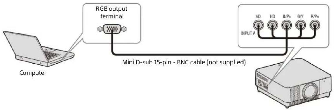
INPUT B
This terminal is used when connecting the projector to a computer with a RGB output terminal. It is recommended that you set the resolution of your computer to 1920 × 1200 pixels for the external monitor.
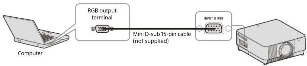
flowchart
graph LR
    A["Computer"] --> B["RGB output terminal"]
    B --> C["Mini D-sub 15-pin cable (not supplied)"]
    C --> D["INPUT & RGB"]
INPUT C
This terminal is used when connecting the projector to a computer with a DVI-D output terminal.
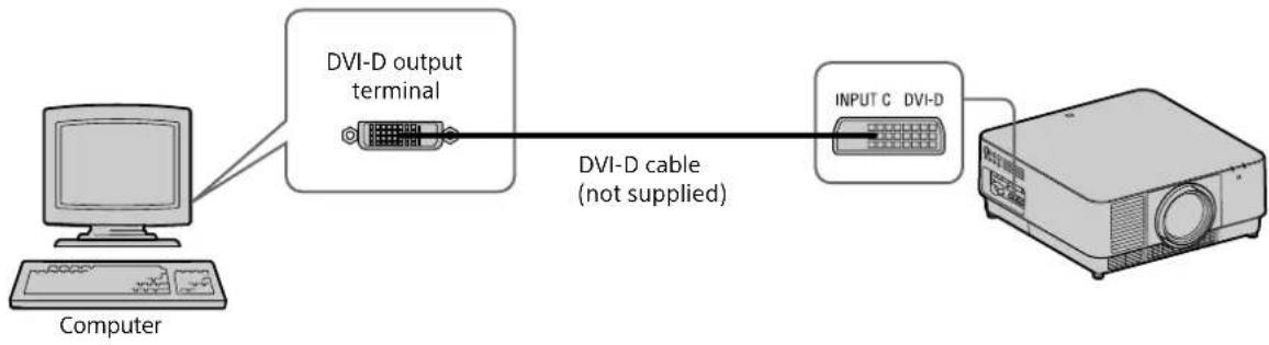
flowchart
graph LR
    A["Computer"] --> B["DVI-D output terminal"]
    B --> C["DVI-D cable (not supplied)"]
    C --> D["INPUT C DVI-D"]
    D --> E["Proport"]
INPUT D
This terminal is used when connecting the projector to a computer with a HDMI output terminal.
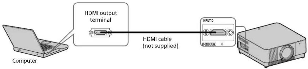
flowchart
graph LR
    A["Computer"] --> B["HDMI output terminal"]
    B --> C["HDMI cable (not supplied)"]
    C --> D["INPUT D"]
Notes
- Use HDMI-compatible device which has the HDMI Logo.
- Use a high speed HDMI cable(s) on which the cable type logo is specified. (Sony products are recommended.)
- The HDMI terminal of this projector is not compatible with DSD (Direct Stream Digital) signal or CEC (Consumer Electronics Control) signal.
Connecting to a Video Device
INPUT A
This terminal is used when connecting the projector to a video device over a long distance.
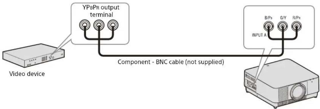
flowchart
graph TD
    A["Video device"] --> B["YPBPR output terminal"]
    B --> C["Component - BNC cable (not supplied)"]
    C --> D["INPUT A"]
    D --> E[" projector"]
    style A fill:#f9f,stroke:#333
    style D fill:#ccf,stroke:#333
INPUT D
This terminal is used when connecting the projector to a video device with a HDMI output terminal.
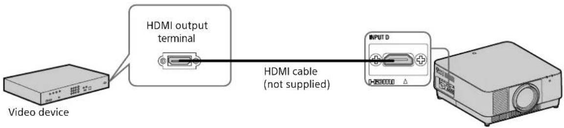
flowchart
graph LR
    A["Video device"] --> B["HDMI output terminal"]
    B --> C["HDMI cable (not supplied)"]
    C --> D["INPUT D"]
    D --> E[" projector"]
Notes
- Use an HDMI cable with the HDMI logo.
- The HDMI terminal of this projector is not compatible with DSD (Direct Stream Digital) signal or CEC (Consumer Electronics Control) signal.
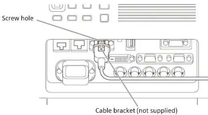
To fix the HDMI cable
As shown in the following figure, fix the HDMI cable to the screw hole above the terminal using a commercially available-cable bracket.
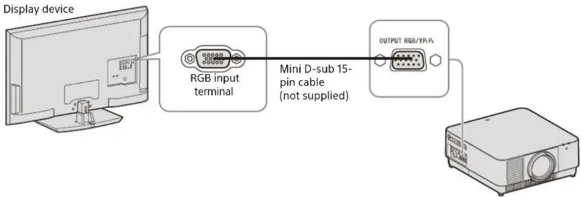
Connecting to an External Monitor
OUTPUT
This terminal outputs projected images. The images are output when a computer signal is input from the RGB input terminal (INPUT A, INPUT B) or a video signal is input from the YP_BP_R input terminal (INPUT A).
Connecting to a Network Equipment
Using a LAN terminal
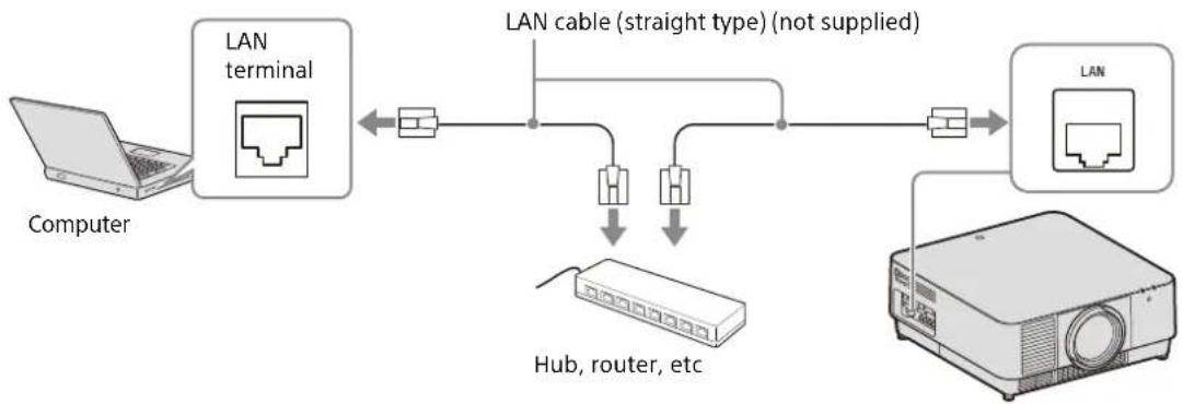
flowchart
graph LR
    A["Computer"] --> B["LAN terminal"]
    B <--> C["LAN cable (straight type) (not supplied)"]
    C --> D["Hub, router, etc"]
    D --> E["Browser"]
    E --> F["LAN"]
Notes
- When using network features via the LAN terminal, be sure to check if "LAN Setting" is set to "LAN Port" (page 31).
- Connect the projector to the network that is constructed to control the access from the internet, such as LAN. If the projector is connected directly to the internet, the security risk is increased.
When you monitor and control the projector via the network, access the Setup page of the projector (page 41) via a Web browser and enable the desired control protocol.
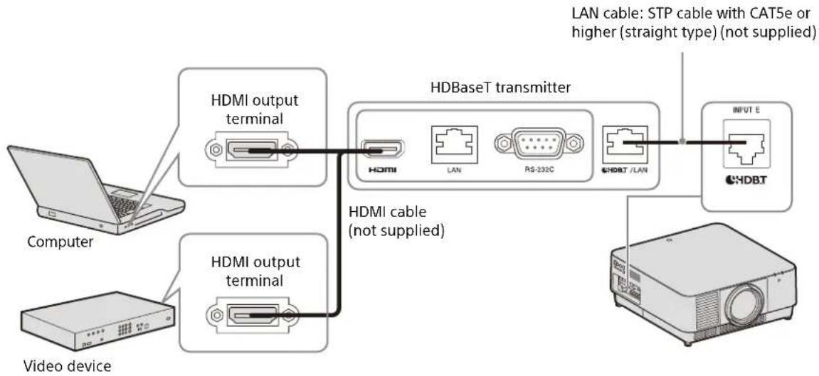
Connecting to a HDBaseT™ Device
The HDBaseT transmitter is used when connecting the projector to a computer, video device, or network equipment.
Notes for connecting this unit to the HDBaseT transmitter
- Ask a professional or Sony dealer to perform wiring. If wiring has been insufficiently performed, it affects the transmission characteristics of the cable, and causes broken or unstable images.
- Connect the cable directly to the HDBaseT transmitter without going through a hub or router.
- Use cables that meet the following conditions.
- CAT5e or higher
- Shielded type (covering connectors)
- Straight wire connection
- Single wire
- When installing the cables, use a cable tester, cable analyzer, or similar device to check if the cables meet the CAT5e or higher requirement. If there is a transit connector between this unit and the HDBaseT transmitter, include it when measuring.
- To reduce the affect of noise, install and use the cable in a manner where it is not rolled up and it is as straight as possible.
• Install the cable away from the other cables (especially the power cable). - When installing multiple cables, do not bind them and keep the running parallel distance as short as possible.
- The transmittable distance of the cable is 100 m (approx. 328 feet) maximum. If it exceeds 100 m (approx. 328 feet), it may cause broken images or a malfunction in LAN communication. Do not use the HDBaseT transmitter beyond the maximum transmittable distance of the cable.
- For operation or function problems caused by devices of other manufacturers, contact the relevant manufacturer.
Connecting to a computer/video device
INPUT E
flowchart
graph TD
    A["Computer"] --> B["HDMI output terminal"]
    C["Video device"] --> D["HDMI output terminal"]
    B --> E["HDBaseT transmitter"]
    D --> E
    E --> F["INPUT E"]
    E --> G["HDBT"]
    style A fill:#f9f,stroke:#333
    style C fill:#f9f,stroke:#333
    style B fill:#ccf,stroke:#333
    style D fill:#ccf,stroke:#333
    style E fill:#cff,stroke:#333
    style F fill:#ffc,stroke:#333
    style G fill:#ffc,stroke:#333
    note right of E: LAN cable: STP cable with CAT5e or higher (straight type) (not supplied)
Connecting to a network equipment (using an HDBaseT terminal)
The HDBaseT terminal is used when connecting the projector to a network equipment to control the projector.
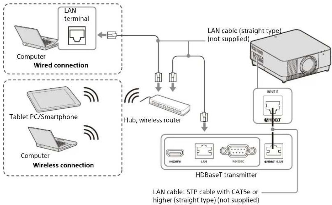
flowchart
graph TD
    A["Computer Wired connection"] --> B["LAN terminal"]
    B --> C["LAN cable (straight type) (not supplied)"]
    D["Tablet PC/Smartphone"] --> E["Hub, wireless router"]
    F["Computer Wireless connection"] --> E
    E --> G["HDBaseT transmitter"]
    G --> H["INPUT E"]
    H --> I["HDBT / LAN"]
    I --> J["LAN cable: STP cable with CAT5e or higher (straight type) (not supplied)"]
Notes
- When using network features, be sure to check if "LAN Setting" is set to "via HDBaseT" (page 31).
- Connect the projector directly to the HDBaseT transmitter without going through a hub or router.
- Set "Extron XTP" in the Connection/Power menu to "On" when connecting to XTP Systems manufactured by Extron Electronics (page 31).
When you monitor and control the projector via the network, access the Setup page of the projector (page 41) via a Web browser and enable the desired control protocol.
Attaching the Projection Lens
Notes
- Avoid removing/attaching the lens with the projector installed suspended from a ceiling.
- For usable projection lenses, see "Optional accessories" (page 54).
- Do not attach any lens other than the specified accessory lens sold separately.
- Be careful not to drop the projection lens.
- Avoid touching the lens surface.
1 Turn off the projector, then unplug the AC power cord from the wall outlet.
Caution
When replacing the lens, your eyes may be damaged if a strong light accidentally gets into your eyes. Before replacing the lens, turn off the projector and then unplug the AC power cord.
2 Remove the lens cover.
While sliding the LENS COVER RELEASE buttons inward, pull out the lens cover until it clicks into place.
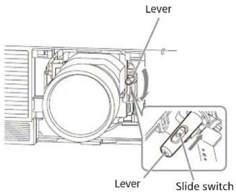
3 Turn the contact substrate to the left facing the front of the lens and insert the lens to the end.
4 While pressing the slide switch, lower the lever until it clicks into place.
5 Attach the lens cover.
Hang the upper side of the lens cover on the top cover of the projector and press it until it clicks into place. Then, while sliding the LENS COVER RELEASE buttons inward, insert the lens cover.
Even when the lens is attached, you can attach/remove the lens cover in the same way.
Removing the Projection Lens
1 Return the projection lens to the center position.
While the projector is turned on, press the LENS SHIFT key on the Remote Commander, then press the RESET key on it. The projection lens returns to the center position.
2 Turn off the projector, then unplug the AC power cord from the wall outlet.
Caution
When replacing the lens, your eyes may be damaged if a strong light accidentally gets into your eyes. Before replacing the lens, turn off the projector and then unplug the AC power cord.
3 Remove the lens cover.
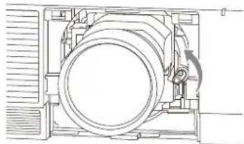
4 While pressing the slide switch, move the lever up to the limit, and pull the lens straight out.
natural_image
Technical line drawing of a mechanical component with no visible text or symbols5 Attach the lens cover.
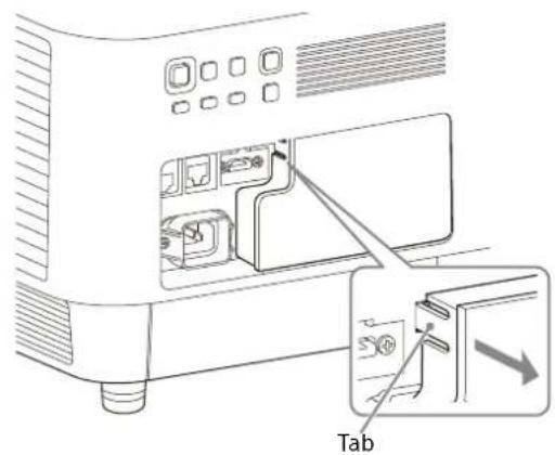
Attaching the Terminal Cover
You can attach the supplied terminal cover when the LAN terminal, INPUT D (HDMI), or INPUT E (HDBaseT) is limited to use for connection.
Attaching the supplied terminal cover prevents dust from entering the terminals and maintains a neat appearance.
Note
The terminal cover may not be attached depending on the condition of the connected cables or installation methods, such as directly placing the unit on the floor. However, this has no impact on normal use.
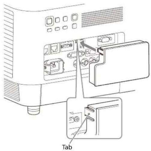
1 Insert the tab of the terminal cover into the slot and attach the terminal cover.
Make sure that the tab of the terminal cover is firmly inserted.
Removing the Terminal Cover
1 Pull out the terminal cover while pressing the tab.
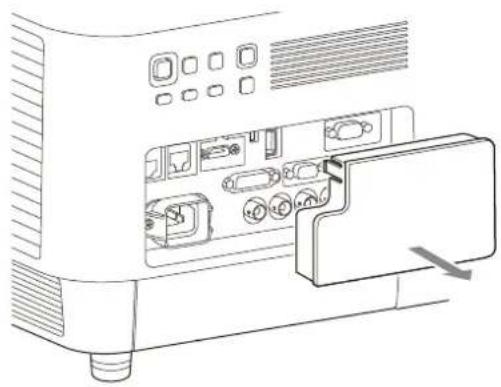
natural_image
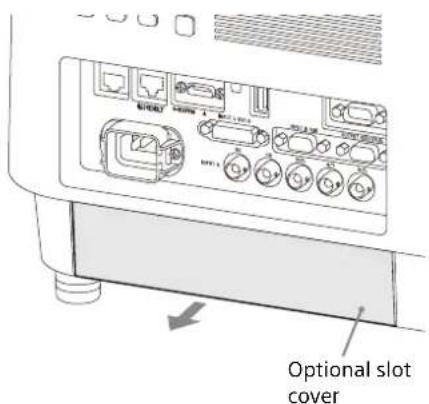
Line drawing of an electronic device showing internal components and a close-up of a cable or connector (no text or symbols)Installing the Optional Adaptor
When installing an optional adaptor (not supplied) into the optional adaptor slot on the terminals of the projector, you can use the optional adaptor as INPUT F.
Notes
- Be sure to retain the optional slot cover removed when installing the optional adaptor. When removing the optional adaptor, attach the cover.
- For details on available optional adaptors, see "Optional accessories" (page 54).
- Do not install optional adaptors other than the one specified as the optional accessory.
- For details on how to use, also refer to the operating instructions of the optional adaptor.
1 Turn off the projector, then unplug the AC power cord from the wall outlet.
2 To remove the optional slot cover attached to the terminals, press the lower part of the optional slot cover.
3 Insert the optional adaptor as far as it goes.
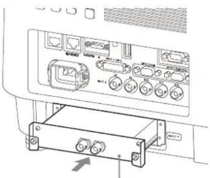
Example: 3G-SDI INPUT Adaptor (not supplied)
4 Tighten the two screws on the optional adaptor.
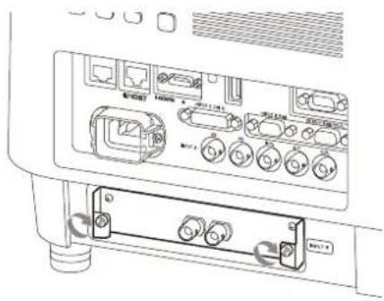
natural_image
Technical line drawing of a device rear panel with ports and connectors (no text or symbols)Projecting/Adjusting an Image
Projecting an Image
The size of a projected image depends on the attached lens or the distance between the projector and screen. Place the projector so that the projected image fits the screen size. For details on projection distances and projected image sizes, see "Projection Distance and Lens Shift Range" (page 58).
1 Plug the AC power cord into a wall outlet.
2 Connect all necessary devices to the projector (page 8).
3 Turn on the projector.
Press the I/⏻ key on the main unit or the I key on the Remote Commander.
4 Turn on the connected device.
5 Select the input source.
Press the INPUT key on the projector or on the Remote Commander to display the input select window. Press the INPUT key repeatedly or the / key to select an image to be projected. The signal icon appears on the right side in the input select window when a signal is input. ^*1
Also, you can select an input signal on the Remote Commander.
*1: When INPUT F is input with the compatible optional adaptor attached, the signal icon always appears.
6 Change the computer screen output destination to an external display.
How to change the output destination varies depending on the type of computer.
(Example)

7 Adjust the projected image (page 17).
Turning Off the Power
1 Press the I/⏻ key on the main unit or the ⏻ key on the Remote Commander.
The shutdown process is started and the projector enters the standby mode.
For long-term use, turn off the projector when not in use.
2 Unplug the AC power cord from the wall outlet.
Adjusting the Projected Image
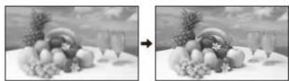
Focusing the image (Focus)
natural_image
Two grayscale images showing a fruit arrangement on a table, one with a rainbow and the other with fruits and flowers (no text or symbols)When attaching the Electric focus lens
Press the FOCUS key on the projector or the Remote Commander then press the /// key.
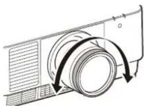
When attaching the Manual focus lens
Turn the focus ring.
natural_image
Diagram of a camera with a rotating lens and directional arrows indicating rotation (no text or symbols)Adjusting the image size (Zoom)
When attaching the Electric zoom lens
Press the ZOOM key on the projector or the Remote Commander then press the /// key.
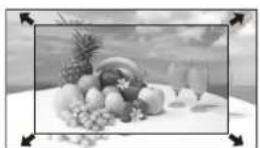
Adjusting the position of the image (Lens shift)
Press the LENS SHIFT/SHIFT key on the projector or the Remote Commander then press the /// key.
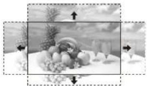
natural_image
Black-and-white photo of a table with assorted fruits and vegetables, no visible text or symbolsTo return the lens to the center position of the projected image
Press the RESET key on the Remote Commander while adjusting the position of the image.
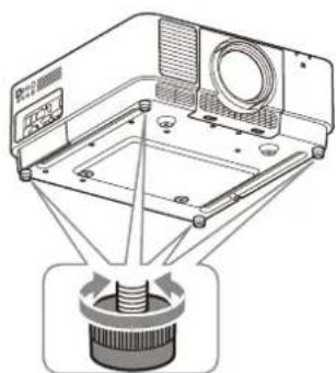
Adjusting the tilt of the projector with the adjustable feet
When the projector is placed on an uneven surface, adjust it using the adjustable feet.
natural_image
Technical line drawing of a mechanical assembly with no visible text or symbolsNotes
- Be careful not to pinch your fingers.
- Do not push hard on the top of the projector with the adjustable feet extended. It may cause a malfunction.
Displaying a pattern for adjusting an image
You can display a pattern for adjusting the projected image with the PATTERN key on the Remote Commander. Use / to change the pattern and / to change its color. Press the PATTERN key again to restore the previous image.
Correcting for Trapezoidal Distortion of the Projected Image (Keystone Adjustment)
If the screen is tilted, or you are projecting from an oblique angle, perform keystone adjustment.
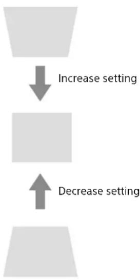
If the projected image is trapezoidally-distorted in the vertical plane
1 Press the KEYSTONE key on the Remote Commander once or select "Screen Fitting" in the Installation menu (page 33).
2 Select "V Keystone."
3 Adjust the value using / . The higher the setting, the narrower the top of the projected image. The lower the setting, the narrower the bottom of the projected image.
flowchart
graph TD
    A["Start"] --> B["Increase setting"]
    B --> C["End"]
    C --> D["Decrease setting"]
Press the RESET key to restore the projected image before adjustment. ^*1
If the projected image is trapezoidally-distorted in the lateral plane
1 Press the KEYSTONE key on the Remote Commander once or select "Screen Fitting" in the Installation menu (page 33).
2 Select "H Keystone."
3 Adjust the value using ◀/►.
The higher the setting, the narrower the right side of the projected image. The lower the setting, the narrower the left side of the projected image.

natural_image
Simple diagram showing two gray squares with one square pointing left and the other right (no text or symbols)Increase the setting

natural_image
Simple diagram showing a gray arrow pointing right to a gray rectangle (no text or symbols)Decrease setting
Press the RESET key to restore the projected image before adjustment. ^*1
*1: The setting may not be reset depending on the combination of adjustment values of the Screen Fitting setting items. In this case, reset all of the Screen Fitting setting items.
Notes
- Keystone adjustment is an electronic correction. Consequently the image quality may deteriorate.
- Depending on the position adjusted with the lens shift feature, performing keystone adjustment may change the aspect ratio of the original image, or the projected image may be distorted.
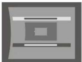
Correcting Image Twist (Warp Correction Feature)
1 Press the KEYSTONE key on the Remote Commander once or select "Screen Fitting" in the Installation menu (page 33).
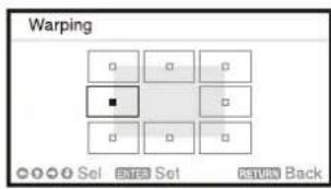
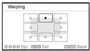
2 Select "Warping." The guide is displayed.
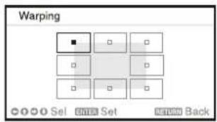
When correcting the corner(s) of the image
1 Move ■ using ↑/↓/↔/→ to select the corner you want to correct.
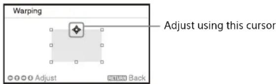
2 Press the ENTER key. The cursor appears.
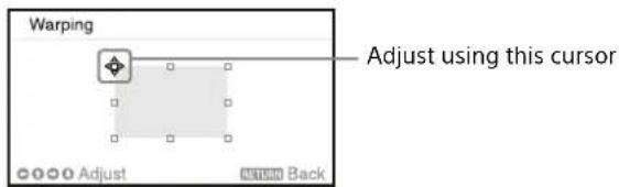
3 Adjust the position of the corner you want to correct, using /// .
natural_image
Abstract geometric design with layered panels and black-and-white highlights (no text or symbols)Press the RESET key to restore the projected image before adjustment. ^*1
When correcting deflection on the left/right side of the image
1 Move ■ using ↑/↓/↔/→ to select the side you want to correct.
2 Press the ENTER key. The cursor appears.
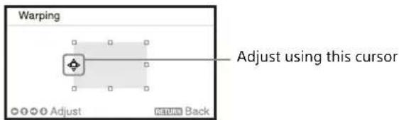
3 Adjust the deflection of the side, using /// .
You can adjust the center point of deflection using / . For the range of deflection, use / . You can separately adjust the left/right side.
natural_image
Abstract geometric pattern with layered rectangular shapes (no text or symbols)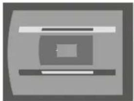
natural_image
Abstract geometric shape with layered rectangular elements (no text or symbols)Press the RESET key to restore the projected image before adjustment. ^*1
When correcting deflection on the top/bottom side of the image
1 Move ■ using ↑/↓/↔/→ to select the side you want to correct.
2 Press the ENTER key. The cursor appears
3 Adjust the deflection of the side, using // / .
You can adjust the center point of deflection using ◀/►. For the range of deflection, use ↑/↓. You can separately adjust the top/bottom side.
natural_image
Abstract geometric design with layered rectangular shapes and central square (no text or symbols)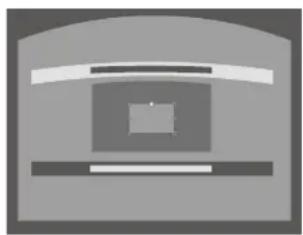
natural_image
Simple grayscale icon of a computer monitor with no text or symbolsPress the RESET key to restore the projected image before adjustment. ^*1
*1: The setting may not be reset depending on the combination of adjustment values of the Screen Fitting setting items. In this case, reset all of the Screen Fitting setting items.
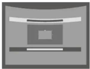
Blending Projections from Multiple Projectors on a Screen
Notes
- Depending on the blending start position or the blending width, the menu may overlap with the blending area and become invisible. If you want to operate the projector while viewing the menu, set "Edge Blending" to "Off" once and make adjustments. Then, set "Edge Blending" to "On."
- The procedure shown above is for general guidance. You may adjust the settings to the situation.
- When multiple projectors are set up in a line, the temperature inside the projectors may increase due to exhaust vent proximity, and an error indication may result. In this case, space the projectors farther apart and/or install deflection partitioning between them. For more details, consult with qualified Sony personnel.
1 Place the projectors.
Input a pattern, etc., to adjust the projected positions from multiple projectors.
2 Set the ID mode.
Set a different ID mode for each projector (page 30).
3 Set the picture mode.
Set "Picture Mode" of the multiple projectors to "Multi Screen" (page 24).
4 Unify the color space.
Set the color space of the multiple projectors to the same mode (Custom 1 to 3) (page 25). R/G/B can be finely adjusted as necessary.
5 Adjust the color matching setting.
Finely adjust each tone as necessary (page 33).
6 Set the Edge Blending setting.
When overlaying multiple projections, the Edge Blending setting is available.
Select "Multi Screen" in the Installation menu, then select "Edge Blending" (page 33).
7 Enable the Edge Blending function.
In "Blend Settings" of the Installation menu, set "Edge Blending" to "On" for each blending position (page 33).
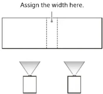
8 Set the blending width.
Set the blending width according to the overlapping range for the source signal.
9 Finely adjust the overlapped area of the image.
You can adjust it in "Blend Fitting" of the Installation menu (page 33).
10 Adjust each correction zone for the most uniform black level between each zone.
You can adjust it by "Zone Black Level." During this adjustment, a black image is automatically projected (page 34).
Using Convenient Functions
Selecting the Stored Picture Settings (Picture Position Function) (Specified Lens Only)
Using the POSITION key on the Remote Commander, you can select one of the combinations of lens settings (focus, picture size (Zoom), picture position (Lens shift)) from six stored settings. When you select the lens settings, the lens move to the stored position of the image (page 30).
1 Press the POSITION key.
The Picture Position selecting palette is displayed.
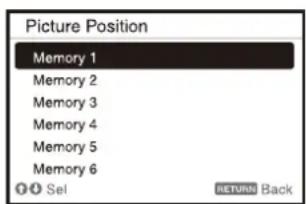
2 Press the POSITION key repeatedly, or press / to select the lens settings.
The selected setting is called up from "Memory 1" to "Memory 6."
Store or delete the lens settings in "Picture Position" of the Screen menu (page 27).
Notes
- After you have selected and confirmed the lens settings, the lens starts to move. Do not touch the lens or place anything near the lens. Doing so may cause injury or a malfunction.
- If you press any key on the Remote Commander or the unit while the lens is moving, the lens stops. In this case, select the lens settings again or adjust the projected position.
- The Picture Position function is not guaranteed to reproduce the lens settings precisely.
- For details on the specified lens, see "Optional accessories" (page 54).
Enlarging a Part of the Image (Digital Zoom Function)
Using the D ZOOM (Digital Zoom) key on the Remote Commander, you can enlarge a part of the image while projecting. This function is available when a computer signal is input.
Note
The D ZOOM (Digital Zoom) key may not be enabled depending on the resolution of the input signal or when displaying two pictures.
1 Press the D ZOOM + key to display the digital zoom icon on the projected image.
2 Press the ♦/♦/♦/♦ keys to move the digital zoom icon to the point on the image you wish to enlarge.
3 Press the D ZOOM + key or the D ZOOM - key repeatedly to change the enlargement ratio. The image can be enlarged up to 4 times.
Press the RESET key to restore the previous image.
Projecting Images with Two Pictures Simultaneously (Two-Picture Display Function)
You can project images from two input signals on the screen as a main picture and subpicture at the same time. To switch between main and sub pictures, press the TWIN key on the Remote Commander.
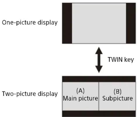
flowchart
graph TD
    A["One-picture display"] <-->|TWIN key| B["Two-picture display"]
    B --> C["(A) Main picture"]
    B --> D["(B) Subpicture"]
You can select the image to project to the main picture.
The subpicture is preset to source the signal input from INPUT B.
Combinations of input signals
| Main picture Subpicture | |
| INPUT A (RGB/YPBPR) | I N P U |
| INPUT B (RGB) - | |
| INPUT C (DVI-D) | INPUT B (RGB) |
| INPUT D (HDMI) | |
| INPUT E (HDBaseT) | |
| INPUT F (Optional adaptor) | |
T
Notes
- When "Screen Aspect" (page 34) is set to "4:3," the two-picture display function is not available.
- While displaying two pictures, the input signal icon does not appear in the input select window (page 16).
- Picture settings set for one picture may not be reflected as two pictures.
- While displaying two pictures, the I (On) key, ⏻ (standby) key, INPUT key, and BLANK key are available.
Adjustments and Settings Using a Menu
Using a Menu
Note
The following menu displays used for the explanation may be different depending on the model you are using.
1 Press the MENU key to display the menu.
2 Select the setting menu.
Use the ↑ or ↓ key to select the setting menu, then press the ➤ or ENTER key.
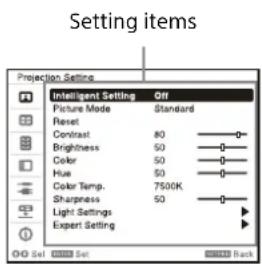
Setting menu
3 Select the setting item.
Use the or key to select the setting item, then press the or ENTER key. To return to the selection screen of the setting menu, press the key or RETURN key.
4 Make the setting or adjustment for the selected item.
Menu operation differs depending on the setting item. When the next menu window is displayed, follow step 3 to set and adjust the selected item.
To reset the setting value of an item to its factory preset value, press the RESET key during setting or adjusting.
Using a pop-up menu
Press the /// key to select an item.
Press the ENTER key to register the setting and return to the previous screen.
Selecting items
Using the setting menu
Press the ↑ or ↓ key to select the item. Press the ENTER key to register the setting and return to the previous screen.
Using the adjustment menu
To increase the number, press the or key and to decrease the number, press the or key.
Press the ENTER key to register the setting and return to the previous screen.
5 Press the MENU key to clear the menu.
The menu disappears automatically if no key is pressed for a while.
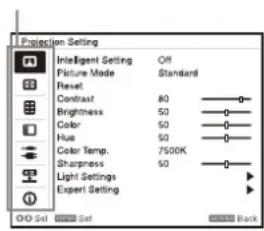
Projection Setting Menu
The Projection Setting menu is used for optimum settings appropriate to the installation location and picture adjustments for input signals.
| Setting items Description | |
| Intelligent Setting | On/Off: When you set to “On,” you can optimize the picture settings, light settings, and system cooling performance (fan rotation speed) by selecting the installation location from "Location" according to the environment in which the projector is used. This setting is for stable and prolonged use of the projector.Location: Select usage location of the projector from the following options. If you cannot find the appropriate option in “Location,” select the closest one.NoteUsage location cannot be selected from “Location” for each input terminal.Meeting/Class Room: Sharply projects text and graphics. This is suitable for use in meeting rooms or classrooms.Museum: Precisely reproduces colors. This is suitable for use in quiet places, such as galleries or museums.Entertainment: Produces well-contrasted pictures. This is suitable for use at theme parks, public entertainment facilities, conference rooms in the exhibition hall, and so on.Multi Screen: This is suitable when simultaneously using multiple projectors for projections, such as blending projections or projections from multiple projectors set up side-by-side. |
| Picture Mode | Dynamic: Emphasizes the contrast to produce a “dynamic” picture.Standard: Makes the picture be natural and well balanced.Brightness Priority: Makes the picture bright to suit a bright environment.Multi Screen: Optimizes the picture quality to suit projecting using multiple projectors.sRGB: Displays the picture quality with sRGB color gamut. (For VPL-FHZ131L only)NoteWhen “Intelligent Setting” is set to “On,” “Picture Mode” cannot be set. |
| Reset Each item in “Projection Setting” is initialized to its factory preset value.However, “Intelligent Setting,” “Picture Mode,” and “Color Temp.” (“Custom 1,” “Custom 2,” “Custom 3,” and “Custom 4”) do not return to the factory preset values. | |
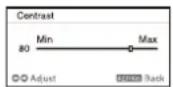
| Contrast The higher the setting, the greater the contrast. The lower the setting, the lower the contrast. | |
| Brightness The higher the setting, the brighter the picture. The lower the setting, the darker the picture. | |
| Color The higher the setting, the greater the intensity. The lower the setting, the lower the intensity. | |
| Hue The higher the setting, the more greenish the picture becomes. The lower the setting, the more reddish the picture becomes. | |
| Color Temp. | 9300K/7500K/6500K: The higher the temperature, the more bluish the picture. The lower the temperature, the more reddish the picture.Brightness Priority 1: Projects images at the maximum brightness.Brightness Priority 2: Projects bright images.Custom 1/ Custom 2/ Custom 3/ Custom 4: An adjusted color temperature setting can be stored for each item.The factory settings are as follows: “Custom 1”: same as the “9300K” setting, “Custom 2”: same as the “7500K” setting, “Custom 3”: same as the “6500K” setting, “Custom 4”: same as the “Brightness Priority 1” setting. |
| Sharpness The higher the setting, the sharper the picture. The lower the setting, the softer the picture. | |
| Light Settings | |
| Dynamic Control | On/Off: Brightness is adjusted automatically according to image content. Dark images are projected with brightness adjusted, leading to energy-saving. Bright images are projected brightly, without adjusting brightness. |
| Light Output Mode Adjusts brightness of the light source.Standard: The image becomes brighter, and power consumption becomes higher.Middle: Power consumption becomes lower; however, the image will darken.Low: Power consumption becomes even lower and the image will darken further.Extended: The images becomes dark but extended projection is enabled.Custom: You can adjust brightness as prefer.NoteWhen "Intelligent Setting" is set to "On," only "Custom" of "Light Output Mode" in "Light Settings" is selectable and other items cannot be set. | |
| Constant Brightness | On/Off: Available when "Light Output Mode" is set to "Standard," "Middle," "Low," or "Custom." Outputs with a constant brightness at the light source output (approximately 85%) that reduces the percentage of each mode.The projector may not be able to maintain the brightness in an environment with a lot of dust and dirt. |
| Expert Setting | |
| Reality Creation Adjusts the detail and noise processing of images. (Super-resolution function)On: Adjusts the settings of "Reality Creation."Resolution: When you increase the setting value, the texture and detail of the image become sharper.Noise Filtering: When you increase the setting value, the noise (picture roughness) becomes less prominent.Test: On/Off: Switches "On" and "Off" at a certain frequency to check the effect of "Reality Creation."The display position of the status during the test works together with the "Menu Position" setting (page 30).Off: The "Reality Creation" function is not applied.NoteDepending on the input signals, image noise may become more prominent. In that case, adjust the settings of "Reality Creation" before use. | |
| Contrast Enhancer Corrects the level of bright and dark parts automatically to optimize contrast according to a scene. Increases image sharpness and makes image dynamic.High/Middle/Low: You can adjust the contrast enhancer.Off: The "Contrast Enhancer" function is not applied. | |
| Gamma Mode 2.2: Equivalent to a 2.2 gamma curve.2.4: Equivalent to a 2.4 gamma curve.Gamma 3: Applies a gamma curve that prioritizes the brightness to suit use in a relatively bright environment.Gamma 4: Enhances black and white contrast to suit use in a relatively dark environment.DICOM GSDF Sim.: Gamma setting is in accordance with the Grayscale Standard Display Function (GSDF) of the Digital Imaging and Communications in Medicine (DICOM) standards. Available when a computer signal is input from the DVI-D input terminal (INPUT C), HDMI input terminal (INPUT D), or HDBaseT input terminal (INPUT E). This projector is not to be used as a device for medical diagnosis. | |
| Color Space Converts the color space.Custom 1: Produces images with vivid colors.Custom 2: Produces images with muted colors.Custom 3: Reproduces image colors true to the original image source. You can select R/G/B for the selected color space and adjust the R/G/B chromaticity points in the x and y directions in the CIExy chromaticity diagram respectively.Color Select: Select the color to adjust from "Red," "Green," and "Blue."Cyan - Red (x): Adjusts the chromaticity point of the selected color toward cyan-red (x).Magenta - Green (y): Adjusts the chromaticity point of the selected color toward magenta-green (y). | |
Setting items Description
| Color Correction | On: Adjusts the hue, saturation, and brightness for the selected color. Repeat steps 1 and 2 described below to specify the target color.1 Press ↓/↓ to select "Color Select," then press ↓/→ to select the color you want to adjust among "Red," "Yellow," "Green," "Cyan," "Blue," and "Magenta."2 Press ↓/↓ to select "Hue," "Saturation" or "Brightness," then adjust them to suit your taste using ↓/→ while watching the projected picture.Off: The "Color Correction" function is not applied. |
| Film Mode When a video signal is input, this option is available.When a progressive signal is input, this option is not available.Auto: Precisely reproduces the image from a film source to suit the original film source.Normally, select this option.Off: Select this option if the images are rough around the edges when "Auto" is selected. | |
The Screen Menu
For adjusting the size, position, and aspect ratio of the projected image for each input signal.
| Setting items Description | |
| Picture Position | You can store up to six picture positions as combinations of lens settings (focus, picture size (Zoom), picture position (Lens shift)) (page 30). After setting the focus, picture size, and picture position, select from “Save,” “Delete,” or “Select.”Save:Stores the current lens settings (focus, picture size, picture position) in the selected Memory 1 to 6. If a setting is already stored in that position, it is overwritten.Delete:Deletes the stored setting. When the setting is deleted, “Select” is not available.Select:Calls up the selected lens settings.NotesWhen using a non-Picture Position supported-lens, you cannot select the setting in “Picture Position.” For details on the specified lens, see “Optional accessories” (page 54).After you have selected and confirmed the lens settings, the lens starts to move. Do not touch the lens and the area around the lens, otherwise it may cause injury or a malfunction.If you press any key on the Remote Commander or the unit while the lens is moving, the lens stops. In this case, select the lens settings again or adjust the projected position.The Picture Position function is not guaranteed to reproduce the lens settings precisely. |
| Aspect *1 | Changes the aspect ratio of the projected image (page 28). |
| When the computer signal is input | Full 1:Displays the image to fit the maximum projected image size without changing the aspect ratio of the input signal. |
| Full 2:Displays the image to fit the maximum projected image size. | |
| Normal:Displays the image on the center point of the projected image without changing the resolution of the input signal or enlarging the image. | |
| When the video signal is input | 4:3:Displays the image to fit the maximum projected image size with an aspect ratio fixed to 4:3.16:9:Displays the image to fit the maximum projected image size with an aspect ratio fixed to 16:9.Full:Displays the image to fit the maximum projected image size.Zoom:Display the center point of the projected image to zoom. |
| V Center *2 *3 | Adjust the whole projected image by moving up and down on the screen.As the selected number increases, the screen moves up, and as the selected number decreases, the projected image moves down. |
| Vertical Size *2 *3 | Reduces or enlarges the image vertically.The projected image is enlarged as the setting increases and reduced as the setting decreases. If the subtitle of a movie, etc. cannot be seen, use this together with “V Center.” |
| Overscan *2 | On/Off:Hides the outline of the image when set to “On.” Select “On” if noise appears along the edge of the image. |
| Adjust Signal *4 | Adjusts the image of a computer signal. Use this item if the edge of the image is cut and reception is bad. |
| APA *5 *6 | Automatically adjusts the projected image to an optimum quality when you press the ENTER key. |
| Phase *5 | Adjusts the dot phase of the display pixel and the input signal. Set to the value where looks clearest. |
| Pitch *5 | The higher the setting, the wider the horizontal image elements (pitch). The lower the setting, the narrower the horizontal image elements (pitch). |
| Shift *4 | H:The higher the setting, the farther right the image is projected on the screen. The lower the setting, the image farther left.V:The higher the setting, the farther up the image is projected on the screen. The lower the setting, the image farther down. |
Notes
*1: • Note that if the projector is used for profit or for public viewing, modifying the original picture by switching to the aspect mode may constitute an infringement of the rights of authors or producers, which are legally protected.
- Depending on the input signal or "Screen Aspect" setting, setting items for aspect ratio or some other setting items cannot be set in some cases, or changing the aspect ratio setting may have no effect.
- A part of the image may be displayed in black, depending on the setting item.
*2: Available when a video signal is input from the YPsPR input terminal (INPUT A), DVI-D input terminal, HDMI input terminal, HDBaseT input terminal, or optional adaptor.
*3: Available when "Aspect" is "Zoom" and "Screen Aspect" is 16:10 or 16:9.
*4: Available when a computer signal is input from the RGB input terminal (INPUT A, INPUT B) or a video signal is input from the YPBPR input terminal (INPUT A). This option is available only when "Aspect" is set to "Zoom."
*5: Available when a computer signal is input from the RGB input terminal (INPUT A, INPUT B).
*6: If the projected image includes a large amount of black portion around it, the APA function will not work properly and a part of the image may not be displayed on the screen. In addition, an optimum image cannot be obtained, depending on the type of input signal. In this case, adjust the "Phase," "Pitch," and "Shift" items manually.
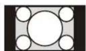
Aspect
| Input signal | Recommended setting value and projected image | |
| Computer signal | (4:3) (Full 1)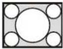 | *1 *2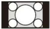 |
(16:9) (Full 1)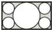 | *1 *2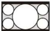 | |
(16:10) (Full 1)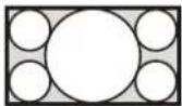 | *1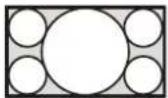 | |
| Video signal | (4:3) (4:3)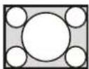 | *3*5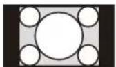 |
(16:9) (16:9)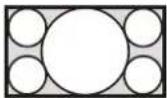 | *4 *5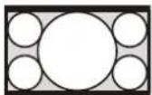 |
*1: If you select "Normal," the image is projected in the same resolution as the input signal without changing the aspect ratio of the original image.
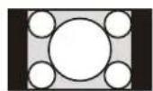

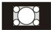
*2: If you select "Full 2," the image is projected to fit the projected image size, regardless of the aspect ratio of the image.
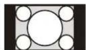

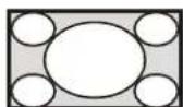
*3: Depending on the input signal, the projected image may be projected as illustrated below. In this a case, select "16:9."
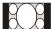

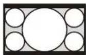
*4: Depending on the input signal, the image may be projected as illustrated below. In this a case, select "Zoom."
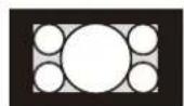

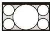
*5: If you select "Full," the image is projected to fit the projected image size, regardless of the aspect ratio of the image.

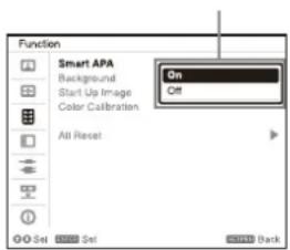
The Function Menu
The Function menu is used for setting various functions of the projector.
| Setting items Description | |
| Smart APA | On/Off: When set to “On,” executes APA automatically when a signal is input.Executes APA when a computer signal is input via the RGB input terminal (INPUT A, INPUT B). |
| Background Enabled when INPUT A, INPUT B, INPUT C, or INPUT D is selected. | |
| Blue/Black/Image/Input-G: Sets the background for when there is no input signal.When set to “Image,” the Start Up Image is displayed. When using the two-picture display mode and there is no input signal, the background will be black even if you set this item to “Image.”When set to “Input-G,” the background changes to INPUT G. The setting is not updated immediately even when selecting “Input-G.” It is reflected the next time when there is no input signal (page 43). | |
| Start Up Image | On/Off: When set to “On,” the Start Up Image is displayed on the screen upon startup of the projector. |
| Color Calibration Corrects color drift on the entire screen that has occurred over time.The color calibration pattern is displayed while selecting this menu. When you press the I/↓ key on the projector or the ↓ key on the Remote Commander, the pattern is turned off and this menu is disabled.Color drift may not be corrected properly due to environmental factors, such as temperature and dust, or changes over time.Auto: If you select “On,” it corrects color drift automatically when the projector is turned off after certain time of use.Start: When twenty minutes have passed after the light has been turned on, it immediately corrects color drift.Return: Restores the settings when performing the previous color calibration. You cannot select this if you have not performed the color calibration.Reset: Restores the factory default settings. | |
All Reset All settings are initialized to their factory preset values.
The Operation Menu
The Operation menu is used for setting for the operations by using the menu or the Remote Commander.
| Setting items Description | |
| Language Selects the language used in the menu and on-screen displays. | |
| Menu Position | Bottom Left/Center: For selecting the position of the menu displayed on the projected image. |
| Status On: All on-screen statuses are enabled.Off: Displays only the menus and warning messages.All Off: Turns off the on-screen displays, other than certain menus.NotesWhen "All Off" is selected, a warning message for high temperature is not displayed, so users are advised to use the projector at their own risk.Note that Sony is not liable for failure of the unit or any accident caused by selecting "All Off." | |
| IR Receiver | Front & Rear/Front/Rear: Selects the remote control receivers (IR Receiver) on the front and rear of the projector. |
| ID Mode | All/1/2/3/4: Assigns an ID number to the projector. When set to "All," you can control the projector with the Remote Commander independently of the assigned ID Mode. Refer also to "ID MODE switch" of the Remote Commander on page 7. |
| Security Lock | On/Off: This function enables restriction of the projector to authorized users by password. The setting procedures for security locking are as follows:1 Select "On" then press the ENTER key to display the setting menu.2 Input the password with the MENU, ♦/♦/♦/♦, and ENTER keys. (The default password setting is "ENTER, ENTER, ENTER, ENTER.")3 Input a new password with the MENU, ♦/♦/♦/♦, and ENTER keys.4 Enter the password again to confirm.Enter the password when you turn on the projector after disconnecting and reconnecting the AC power cord.When it is set to "Off," you can cancel the security lock. You are required to input the password again.If you fail to enter the correct password after three consecutive times, the projector cannot be used. In this case, press the I/↓ key to go standby mode then turn on the power again.NoteYou will not be able to use the projector if you forget your password. Contact qualified Sony personnel for further assistance. You are required to inform the projector serial number and your identity for verification. (This process may differ in other countries/regions.) Once your identity has been confirmed, we will provide you with the password. |
| Control Key Lock | On/Off: When set to "On," locks all the control keys of the projector. However, you can enable operation by performing the following even when "Control Key Lock" is set to "On."Press and hold the I/↓ key for approximately 10 seconds during standby mode.→ The projector turns on.Press and hold the MENU key for approximately 10 seconds during power on.→ "Control Key Lock" is set to "Off" and enables operation of all control panel keys on the projector. |
| Lens Control | On/Off: When set to "On," you can adjusts the lens (focus, zoom, and lens shift) from the Remote commander or the projector. To prevent unintentional operation, set it to "Off" after adjusting the lens. |
The Connection/Power Menu
The Connection/Power menu is used for setting for the connections and power.
| Setting items Description | |
| Network Setting | |
| IPv4 Setting*1 *3 | |
| IP Address Setup | Auto(DHCP): The IP address is assigned automatically from the DHCP server such as a router.Manual: To specify the IP Address manually. |
| IP Address/ Subnet Mask/Default Gateway/Primary DNS/Secondary DNS | When "Manual" is selected for "IP Address Setup," select the item with the ◆ or ◆ key and input the value with ◆ or ◆ key. When all items are entered, select "Apply" then press the ENTER key. The entered settings will be registered. |
| IPv6 Information Displays the IPv6 address information.When setting the address of IPv6, set it from the browser (page 41). | |
| HDBaseT Settings | |
| LAN Setting | via HDBaseT/LAN Port: You can select either via the LAN of the HDBaseT device connected to the HDBaseT terminal or via the network connection with the LAN terminal of the main unit. *2 *3 |
| RS-232C Setting | via HDBaseT: You can connect this unit to the RS-232C terminal via the HDBaseT transmitter. (Baud rate: 9,600 bps)RS-232C: Use when connecting to the RS-232C terminal of this unit directly. (Baud rate: 38,400 bps) |
| Extron XTP | On/Off: Set to "On" when connecting the HDBaseT terminal of this unit to XTP Systems*4 manufactured by Extron Electronics. Set to "Off" when connecting to other equipment. |
| Dynamic Range *5 | Sets the image input level of the INPUT C/D/E/F terminal.Auto: Distinguishes the image input level automatically.Limited: Set when the image input level is 16-235.Full: Set when the image input level is 0-255. |
| HDMI Cable | Long/Normal: Select "Long" when the image is disturbed or not projected. |
| Input-A Signal Sel. | Auto/Computer/Video GBR/Component: When set to "Auto," selects the type of video signal input automatically when "Input-A" is selected with the INPUT key.*6 |
| Input-G Cont. Sel. | USB/Network: Sets the content for the HTML viewer. You can select "USB" or "Network" to load a file (page 43). |
| ECO | |
| Auto Power Saving *7 | |
| With No Input | Light Cutoff: The light turns off automatically and power consumption is reduced if no signal is input for about two minutes. The light turns on again when a signal is input or any key is pressed. In Light Cutoff, the ON/STANDBY indicator lights in orange (page 46).Standby *8: If no signal is input to the unit for about two minutes, the power turns off automatically, and the unit enters standby mode.Off: The "With No Input" function is disabled. |
| With Static Signal Light Dimming | *9 *10: If an image does not change for about 10 seconds, light output is gradually reduced (approximately 10% to 15% *11) from that set in the Light Output Mode. This setting provides a convenient way to reduce power consumption. In addition, the light automatically darkens slowly to approximately 30% of its light output if the selected time ("5 min," "10 min," "15 min," "20 min," or "Demo.") elapses with no change to input signal. While dimming the light, the message "Light Dimming" appears. If you select "Demo," the image will start to darken about 40 seconds later. When any change in signal is detected, or an operation (Remote Commander or control panel) is performed, normal brightness is restored.Off: The "With Static Signal" function is disabled. |
| Standby Mode *12 | Standard/Low: When set to "Standard," power consumption becomes higher in Standby mode. For details, see "Power consumption (Networked Standby Mode)" in "Specifications" (page 54). |
| Quick Reboot | Off/10 min./30 min.: After you turn off the power, the projector is in standby mode for a quick start within the specified time (10 minutes or 30 minutes). The ON/STANDBY indicator lights in orange when the projector is in standby mode (page 46). |
| Direct Power On | On/Off: When you select “On” and plug the projector, the projection starts without going into standby mode. You can also unplug the AC power cord without going into standby mode when you turn off the projector.You may unplug the AC power cord without going into standby mode. |
*1: Set the IP address of this unit manually after connecting to the network. If this unit is not connected to the network, the setting is not enabled.
*2: When connecting via HDBaseT, only the 100BASE-TX can be used for connection. When using the LAN terminal of the main unit, you can connect with the 10BASE-T/100BASE-TX/1000BASE-T.
*3: The IP addresses when using HDBaseT and when using the LAN terminal should be set respectively.
- Setting the IP address when using a LAN via HDBaseT.
Set "LAN Setting" to "via HDBaseT" in "HDBaseT Settings," then set the IP address in "Network Setting."
- Setting the IP address when using the LAN terminal.
Set "LAN Setting" to "LAN Port" in "HDBaseT Settings," then set the IP address in "Network Setting."
*4: For details on XTP Systems, refer to the product catalog or brochure from Extron Electronics.
*5: If the image input setting of the HDMI connection device is not correct, the brighter part becomes too bright and the darker part becomes too dark.
*6: Depending on the input video signal, the optimal signal type may not be selected. Set manually according to the connected device.
*7: The "Auto Power Saving" function is not enabled for INPUT G.
*8: Select "Off" to avoid entering standby mode when there is no input signal.
*9: A change in signal may not be detected depending on the input image. If "With No Input" is set, it takes priority.
*10: As the light is dimmed gradually, you may not notice any change in brightness.
*11: This varies depending on the "Light Output Mode" setting (page 25).
*12: When "Standby Mode" is set to "Low," the network and network control function cannot be operated while the projector is in standby mode.
The Installation Menu
The Installation menu is used for installing the projector.
| Setting items Description | |
| Screen Fitting Adjusts the distortion of the projected image that occurs due to installation conditions or when a portion of the image spreads beyond the screen.Since the Keystone/Warping/Linearity adjustment is an electronic correction, the image may deteriorate.Warping: Select an adjustment point and move it vertically/horizontally to adjust the image distortion.V Keystone: Adjusts the vertical keystone distortion. The higher the setting, the narrower the upper side of the projected image. The lower the setting, the narrower the lower side of the projected image.*1H Keystone: Adjusts the horizontal keystone distortion. The higher the setting, the shorter the right side of the projected image. The lower the setting, the shorter the left side of the projected image.*1V Linearity: Adjusts the projected image so that the height of the upper half and lower half will be the same. The higher the setting, the narrower the upper half of the projected image. The lower the setting, the narrower the lower half of the projected image.H Linearity: Adjusts the projected image so that the width of the right half and left half will be the same. The higher the setting, the narrower the right half of the projected image. The lower the setting, the narrower the left half of the projected image.Reset: Resets all of the Screen Fitting items. | |
| Multi Screen When composing one screen with multiple projections, you can overlap portions of different projections or tile the projections. | |
| Color Space | Changes the color space. The same adjustments as in “Color Space” (page 25) in the Projection Setting menu are available. The color gamut is independently adjusted when “Picture Mode” is set to “sRGB.” When “Picture Mode” is set to another mode, the color gamut is adjusted in a common setting. |
| Color Matching Adjusts the overall brightness and hue of the projected image.The brightness and color of the projected image may not match completely, even after you adjust “Brightness” and “Color.”Adjust: Select one of 6 signal levels and adjust the brightness or hue.Level 1 - 6: Select the brightness level to adjust.Brightness: Adjusts the brightness of the selected brightness level.Color: Adjusts the hue of the selected brightness level.Reset: Resets all of the adjusted values. | |
| Edge Blending | Reset: Resets all of the Blend Settings, Blend Fitting, and Zone Black Level values. |
| Blend Settings Configure the Edge Blending setting for the top, bottom, right, and left of the screen respectively.Left/Right/Top/Bottom: Set the Edge Blending effect for each position.Edge Blending: Set “On” to set “Blending Range” or “Blend Start Pos.”Blending Range: Set the width where images are overlapped.Blend Start Pos.: Set the start position from which images are overlapped.Blend Cursor: Displays the cursors at the start and end positions for edge blending. When set to “On,” the cursors are displayed during Blend settings.Start Pos. Color: Select the color of the cursor that indicates the start position.End Pos. Color: Select the color of the cursor that indicates the end position.Reset: Resets all of the Blend Settings values. | |
| Blend Fitting Finely adjusts the overlapped part.Adjust: Specify a position in the overlapped area and move image pixels.Use ♦/♦/♦/♦ to select the position to adjust. Press the ENTER key to determine the position and use ♦/♦/♦/♦ to move the image pixels vertically/horizontally so that neighboring images overlap.Reset: Resets all of the Blend Fitting values. | |
| Zone Black Level *2 *3 *4 | Adjusts so that the overlapped part is not noticeably bright when a dark image is displayed.Select the correction zone "Adjust Zone 1" through "Adjust Zone 9," and set the adjustment values.Zone Fitting: Adjusts the area of each correction zone.Adjust: Specifies the position of the marginal line of each correction zone.Select the adjusting position using ♦/♦/♦/♦. Press the ENTER key to determine the position and use ♦/♦/♦/♦ to move the image pixels vertically/horizontally so that the area of each correction zone is adjusted.Reset: Resets all of the Zone Fitting values.Black Level Adj.: Adjusts the brightness of each correction zone.Reset: Resets all of the Black Level values.Reset: Resets all of the Zone Black Level values. |
| Image Split | Off/Left-side Area/Right-side Area: Divides the input signal from the computer in half, and displays an enlarged image of the left-side or right-side area on the screen.If the Screen Aspect is set to 16:10 and input signal is 16:10 or 16:9, the image will be projected at the correct aspect. This function is not available when displaying two pictures. |
| Image Flip | HV/H/V/Off/Auto: Flips the projected image horizontally and/or vertically according to the installation method. |
| High Altitude Mode | On/Auto: Set to "On" when using the projector at an altitude of 1,500 m or higher.Continuing to use the wrong setting may affect component reliability. |
Filter Cleaning Turns off the projector and cleans the air filter in standby mode.Normally, filter cleaning is performed periodically and automatically when turning off the power. However, it is not performed when "Direct Power On" is set to "On" (page 32).Periodically performing "Filter Cleaning" in the above menu is recommended. Filter cleaning is not performed if the AC power cord is unplugged or the projector is placed at an angle as shown below.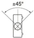 | |
| Screen Aspect | 16:10/16:9/4:3: For switching the display area to suit to the screen. |
| Blanking This feature allows you to adjust the displayable region within the four directions of the projection surface.When the projected image is displayed smaller than the entire projection surface using the Aspect or Screen Aspect setting, blanking may not be applied.Select the edge to adjust from "Left," "Right," "Top," and "Bottom" using the ♦/♦ keys.Adjust the amount of blanking using the ♦/♦ keys. | |
| Panel Alignment This feature allows you to adjust the gaps in the color of characters or the picture.When set to "On," "Adjust Color" and "Pattern Color" can be assigned and adjusted.Depending on the adjustment value of "Panel Alignment," the color and resolution may be changed.Adjust Item: Selects how to make adjustments from below.Shift: Shifts the whole picture and makes adjustments.Zone: Selects the desired range and makes adjustments.Adjust Color: Assigns the desired color to adjust the gaps in color. Select "R" (Red) or "B" (Blue) to make adjustments based on "G" (Green).Pattern Color: Select "R/G" (Red and Green) or "R/G/B" (White, all colors) when "Adjust Color" is "R" (Red). Select "B/G" (Blue and Green) or "R/G/B" (White, all colors) when the "Adjust Color" is "B" (Blue).Adjust: The shift adjustment and zone adjustment of the color selected in "Adjust Color" can be made with ♦/♦/♦/♦ keys.Reset: The panel alignment settings are initialized to their factory preset values. | |
Setting items Description
Uniformity This feature allows you to adjust color uniformity.
Select the appropriate brightness level from level 0 to level 11. Also, select the desired range to adjust the color.
Level: Select the brightness level (0-11) to adjust the brightness of the screen.
Area: Top Left: Select the top-left point to specify the adjustment range.
Area: Bottom Right: Select the bottom-right point to specify the adjustment range.
R: Adjusts the red level in the selected range.
G: Adjusts the green level in the selected range.
B: Adjusts the blue level in the selected range.
Reset: Resets all of the adjusted values.
*1: Depending on the position adjusted with the lens shift feature, the aspect ratio of the image may change from the original or projected image may be distorted with Keystone adjustment.
*2: You cannot adjust anything other than the targeted adjustment zones in "Zone Black Level."
*3: When selecting the correction zone of "Zone Black Level" the targeted correction zone flashes twice.
*4: When entering the Zone Fitting adjustment, the whole screen flashes twice to indicate the division state of the area.
The Information Menu
The Information menu enables you to confirm various information on the projector, such as the total usage hours of a light.
| Items Description | |
| Model Name Displays the model name. | |
| Serial No. Displays the serial number. | |
| fH (horizontal frequency)/fV (vertical frequency) | Displays the horizontal frequency/vertical frequency/signal type of the current input signal.These items may not be displayed depending on the input signal. |
| Light Timer Indicates the total usage time of a light. | |
Using Network Features
Connection to the network allows you to perform the following.
Use the projector with only necessary functions enabled.
- Checking the current status of the projector.
- Remotely controlling the projector.
- Receiving the e-mail report for the projector.
- Making the network settings for the projector.
- Monitoring networks and supporting control protocol (Advertisement, ADCP, PJ Talk, PJ Link, SNMP, AMX DDDP [Dynamic Device Discovery Protocol], Crestron RoomView).
• Using the HTML Viewer Function. - Setting the time for the HTML viewer.
- Restoring the network settings to their factory defaults.
• Using the Software Update Function.
Notes
- When connecting this projector with the network, consult with the network administrator. The network must be secured.
- When using this projector connected with the network, access the control window via a Web browser and change the access limitation of the factory preset values (page 37). It is recommended to change the password regularly.
- When the setting on the Web browser is completed, close the Web browser to log out.
- Supported Web browsers are Internet Explorer (version 11 or later), Safari, and Chrome.
• The menu displays only English. - If the browser of your computer is set to [Use a proxy server] when you have access to the projector from your computer, click the check mark to set accessing without using a proxy server.
- SNMP, AMX DDDP, and Crestron RoomView do not support IPv6.
- The following menu displays used for the explanation may be different depending on the model you are using.
Displaying the Control Window of the Projector with a Web Browser
1 Connect the LAN cable (page 11).
2 Set the network settings for the projector using "Network Setting" in the Connection/Power menu (page 31).
3 Start a Web browser on the computer, enter the following in the address field, then press the Enter key on your computer.
http://xxx.xxx.xxx.xxx
(xxx.xxx.xxx.xxx: IP address for the projector)
When connecting with the IPv6 address http://[xxxx:xxxx:●●● xxxx]
You can confirm the IP address of the projector under "Network Setting" in the Connection/Power menu (page 31).
The following window appears in the Web browser.
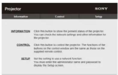
Once you make the network settings, you can open the control window only by performing step 3 of this procedure.
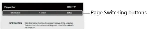
Operating the control window
Switching the page
Click one of the Page Switching buttons to display the desired setting page.
Setting the access limitation
You can limit a user for accessing any particular page.
Administrator: Allowed access to all pages User: Allowed access to all pages except the Setup page
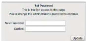
When you access the Setup page for the first time, input "root" as the user name and "Projector" as the password in the authentication dialog.
When you log in for the first time, the window that prompts you to change the password is displayed. Follow the instructions on the screen to change the password.
The name of the administrator is preset to "root."
![Projector SONY Information Control Setup Owner Information Network Password Case & Time Advanced Menu Administrator Name: user Password: Custom Password: Apply User Name: Password: Custom Password: Apply Entry area for Entry area for [User]](/content/2026/05/818370/images/1b15be4b0ddbeb432930a08e27a4777d4d54157eadcf2afa25d3547fa495b4c8.jpg)
Entry area for
Entry area for [User]
[Administrator]
The password can be changed in the Password page in the Setup page.
The password of the administrator and user should be 8 to 16 characters that includes both alphabet and numeric characters. Alphabet is case-sensitive.
The default password "Projector" cannot be set as a new password.
Note
If you forget your password, consult with qualified Sony personnel.
The password will be reset with your permission.
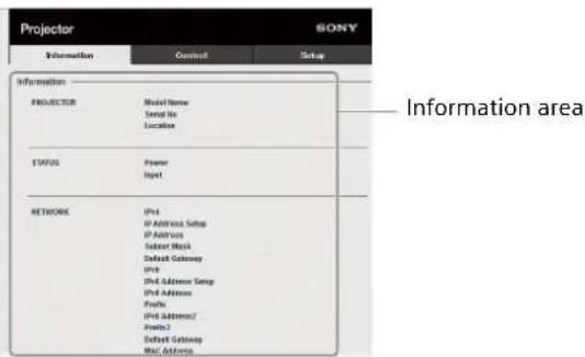
Confirming the Settings for the Projector
You can confirm the current settings for the projector on the Information page.
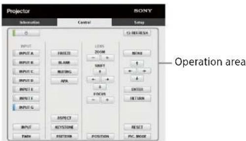
Operating the Projector from a Computer
You can control the projector from the computer on the Control page.
The functions of the buttons shown in the operation area are the same as those of the keys on the supplied Remote Commander.
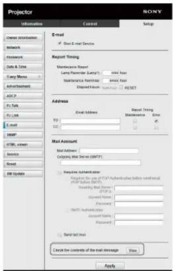
Using the e-mail Report Function
Set the e-mail report function on the Setup page. Entered values will not be applied unless you click on [Apply].
Notes
- The e-mail report function is not available on the network where Outbound Port25 Blocking is used and cannot connect to the SMTP server.
- You cannot enter the following characters in the text box: "","","\","&","<",">"
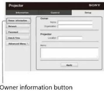
1 Click on [Owner information] to enter the owner information recorded in the e-mail report.
2 Click on [Advanced Menu], then [E-mail] to display the E-mail page.
Set the timing of the e-mail report.
Start E-mail Service: Set the E-mail function to enabled or disabled.
Maintenance Reminder: Set the timing for maintenance. To reset Maintenance Reminder, check the RESET box and then click on [Apply].
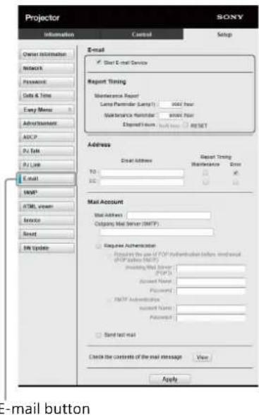
3 Enter the outgoing e-mail address in the Address box then check the Report Timing box of the e-mail report to be sent.
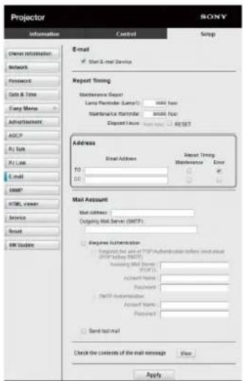
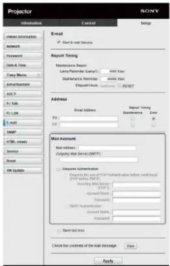
4 Set the mail account for sending e-mail reports.
Mail Address: Enter the e-mail address.
Outgoing Mail Server (SMTP): Enter the address of outgoing mail server (SMTP).
Required Authentication: Check this box if authentication is required for sending e-mail.
Requires the use of POP Authentication before send email (POP before SMTP): Check this box to arrange for POP authentication to be performed before sending e-mail.
Incoming Mail Server (POP3): Enter the address of the incoming-mail server (POP3) to be used for POP3 authentication.
Account Name: Enter the mail account.
Password: Enter the password.
SMTP Authentication: Check this box to arrange for SMTP authentication to be performed before sending e-mail.
Account Name: Enter the mail account.
Password: Enter the password.
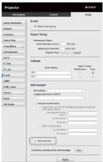
5 Confirm the content of the e-mail report. When you click on [View], the content of the e-mail report are displayed.
6 Send the test mail.
To send your test mail to the preset e-mail address, check the Send test mail box then click on [Apply].
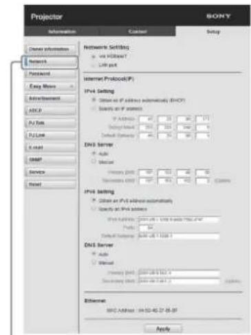
Configure the Network Settings
You can configure the network settings for the projector in "Network Setting" of the Connection/Power menu. Also, you can set the network function on the Setup page. Entered values on the Setup page will not be applied unless you click on [Apply].
1 Click on [Network] to display the Network page.
Network button
2 Set the Internet protocol in [Network Setting].
Via HDBaseT: Set the network settings for the HDBaseT terminal.
LAN port: Set the network settings for the LAN port.
3 Set the items for Internet protocol.
(a) IPv4/IPv6 address
Obtain an IP address automatically (DHCP):
Automatically provides the IP Address provided by a DHCP server.
Specify an IP address: Set the network manually.
-IP Address: Input the IP address of the projector.
-Prefix: For IPv6, input the prefix (bit) of the projector.
-Subnet Mask: Input the subnet mask of the projector.
-Default Gateway: Input the default gateway of the projector.
(b) DNS server
Auto: Automatically provides the IP Address provided by a DHCP server.
Manual
-Primary DNS: Input the primary DNS server of the projector.
-Secondary DNS: Input the secondary DNS server of the projector.
4 Set the items for Ethernet.
MAC Address: Displays the MAC address of the projector.
Note
Different MAC addresses for the HDBaseT terminal or LAN port are provided to the projector.
The DHCP server provides different IP addresses/ DNS for the HDBaseT terminal or LAN port.
Setting the Control Protocol of the Projector
Change the settings for the control protocol on the Setup page.
Entered values will not be applied unless you click on [Apply].
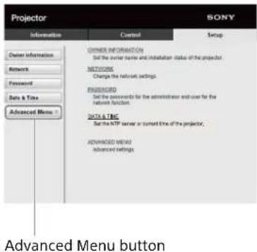
1 Click on [Advanced Menu] to display the Setup page.
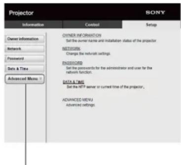
Advanced Menu button
2 Click on [Advertisement] to display the Advertisement page.
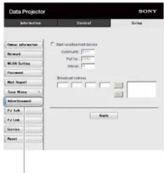
Advertisement button
Start Advertisement Service: Set Advertisement to enabled or disabled. Items for Advertisement are enabled only when this function is enabled.
-Community: Input the community name for Advertisement and PJ Talk. If the community name for Advertisement is changed, the one for PJ Talk will also be changed. Only four alphanumeric characters can be input. The factory default setting is "SONY." To avoid unwanted access to the projector from other computers, changing the community name of the factory default is recommended.
-Port No.: Input the transmit port of Advertisement. The factory default setting is "53862."
-Interval: Input the transmission interval (seconds) of Advertisement. The factory default setting is "30."
-Broadcast Address: Input the destination of data via Advertisement. If nothing is input, the data will be broadcast in the same subnetwork.
3 Click on [ADCP] to display the ADCP page.
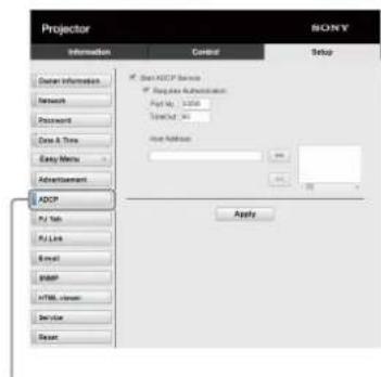
ADCP button
Start ADCP Service: Set ADCP to enabled or disabled. Items for ADCP are enabled only when this function is enabled.
-Requires Authentication: Set the authentication for ADCP to enabled or disabled. The password is the same as that of the Web page administrator.
-Port No.: Input the server port of ADCP. The factory default setting is "53595."
-Timeout: Input the time (seconds) until ADCP communication is terminated in case it is disconnected. The factory default setting is "60."
-Host Address: Input the IP address that the ADCP server is allowed to receive. If no IP address is input, receiving commands will be allowed from any IP address. From the moment the IP address is input, access will be allowed only from that input IP address. For security reasons, it is recommended to input an IP address to restrict access.
4 Click on [PJ Talk] to display the PJ Talk page.
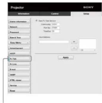
PJ Talk button
Start PJ Talk Service: Set PJ Talk to enabled or disabled. Items for PJ Talk are enabled only when this function is enabled.
-Community: Input the community name of Advertisement and PJ Talk. If the community name for PJ Talk is changed, the one for Advertisement will also be changed. Only four alphanumeric characters can be input. The factory default setting is "SONY." To avoid unwanted access to the projector from other computers, changing the community name of the factory default is recommended.
-Port No.: Input the server port of PJ Talk. The factory default setting is "53484."
-Timeout: Input the time (seconds) until PJ Talk communication is terminated in case it is disconnected. The factory default setting is "30."
-Host Address: Input the IP address that the PJ Talk server is allowed to receive. If no IP address is input, receiving commands will be allowed from any IP address. From the moment the IP address is input, access will be allowed only from that input IP address. For security reasons, it is recommended to input an IP address to restrict access.
5 Click on [PJ Link] to display the PJ Link page.
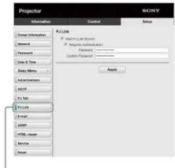
PJ Link button
Start PJ Link Service: Set PJ Link to enabled or disabled. Items for PJ Link are enabled only when this function is enabled.
-Requires Authentication: Set the authentication for PJ Link to enabled or disabled.
-Password: Input the authentication password for PJ Link.
6 Click on [PJ Control API] to display the PJ Control API page.
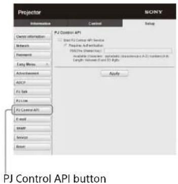
Start PJ Control API Service: Set PJ Control API to enabled or disabled.
-Requires Authentication: Set the authentication for PJ Control API to enabled or disabled.
-PSK(Pre-Shared Key): Input the PSK (Pre-Shared Key) for authentication. Only 8 to 63 alphanumeric characters can be input.
7 Click on [Service] to display the Service page. The system service function is set.
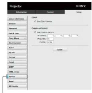
Service button
Start DDDP Service: Set DDDP to enabled or disabled. For details, refer to the DDDP specifications from AMX Corporation.
Crestron Control: Set Crestron Control to enabled or disabled. For details, refer to the product catalogues, etc., from Crestron Corporation.
-IP Address: Input the Crestron system server.
-IP ID(HEX): Input the IP ID(HEX) for the CIP protocol.
-Port No.: Input the port number for the CIP protocol server.
Resetting the network settings
Reset the network settings to their factory defaults.
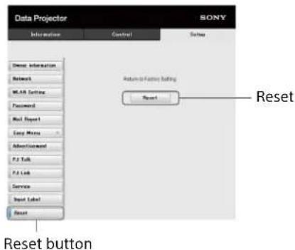
Reset: Reset all Web browser settings to their factory defaults.
About the HTML Viewer Function
You can set the HTML viewer (INPUT G) as the background when no signal is input to the projector or the projector is not operated. Select "Input-G" in "Background" of the Function menu when using the HTML viewer. When no signal is detected, the input source automatically switches to INPUT G. When an input signal is detected, it switches from INPUT G to the previous input signal.
Recommended format for still images (For tag)
| Format Resolution | |
| JPEG | Up to 1920×1080 |
| PNG | |
| BMP | |
| GIF | |
The HTML viewer function is displayed by INPUT G. Switch to INPUT G using the input key on the Remote Commander.
The HTML file can be loaded from the network or USB memory.
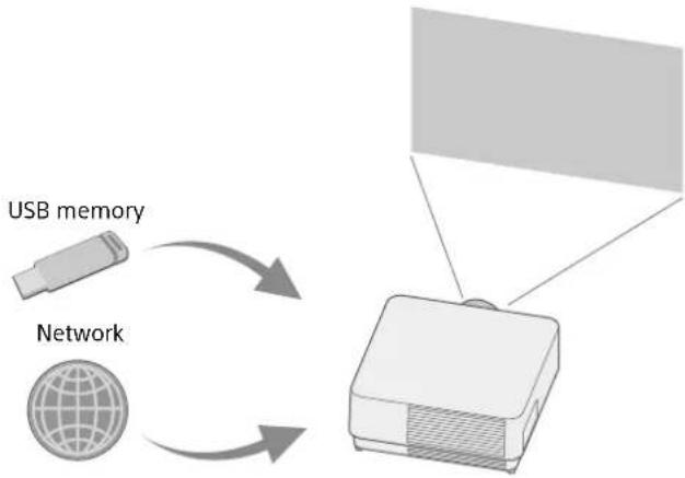
flowchart
graph TD
    A["USB memory"] --> B["Network"]
    B --> C[" projector"]
    C --> D["Output"]
About the content
- The content is displayed at 1920×1080 fixed resolution.
- You can set the time used on the HTML viewer in the Date & Time page (page 45).
- You can reload the content using the ENTER key on the Remote Commander or the unit.
Displaying the HTML content of the USB memory on the HTML viewer
1 Set "Input-G Cont. Sel." to "USB" in the Connection/Power menu (page 31).
2 Prepare HTML content.
The HTML content consists of element of title, image, and text and index.html is specified as the file name.
3 Store the HTML content in the root folder of a USB memory.
The root folder is the first or top-most directory in a hierarchy of the USB memory.
4 Insert the USB memory to the USB port of the main unit (page 5).
Displaying the HTML content on the HTML viewer via the network
1 Set "Input-G Cont. Sel." to "Network" in the Connection/Power menu (page 31).
2 Configure the network settings (page 31).
3 Specify the HTML content location in the network.
Setting the HTML viewer
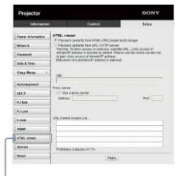
HTML viewer button
Read the HTML contents from inserted USB memory: Read an HTML file from the USB memory.
Playback contents from URL (HTTP server): Load an HTML file via a network.
URI: When loading the content via a network, enter the content location (URI).
Address: When loading the content via a network, enter the address of the proxy server used in the network. Refer to the following and enter the address. Do not enter schemes such as http.
For example: sample_proxy.proxy.com Port: When loading the content via a network, enter the port of the proxy server used in the network.
URL Control Access List ^*1 : Enter the URL for the HTML file to access to.
*1 Enter the full URL including the URL that you entered in the URI field. The HTML file will be denied access to the URL without entries and the content is not displayed.
Notes
- While displaying two pictures, the background will be black even if "Background" is set to "Input-G" in the Function menu.
- The USB 2.0 memory device of up to 8 GB is available for the projector. However, all the USB memory devices are not guaranteed for use on the projector.
When you format the USB memory, make sure to do so with a FAT32 file system. If you format the USB memory with a file system other than FAT32, you cannot use the USB memory for the projector. -
The same languages used in the projector are supported. However, special characters may not be displayed. You cannot add more fonts and languages.
-
The HTML content should be less than 512 MB. HTML content larger than 512 MB may not be displayed appropriately.
- Some types of content or the network environment may affect the connection quality such. For example, loading may take a longer time.
- The "Auto Power Saving" function is not enabled while using the HTML viewer (page 31).
- The HTML viewer does not have an interface to work on the content, such as selecting a button or link displayed on the content. You cannot close the window, warning dialog, or authentication message on the content. Scrolling a window on the HTML viewer is not available. Set the content size in advance to fit in the window of the projector.
- Browser extensions, such as plug-in cannot be installed on the projector.
- The content cannot be displayed if it is encrypted by protocol such as SSL or TSL.
Setting the time (for the HTML viewer)
You can set the date and time for the HTML viewer. Use the date and time set in advance for INPUT G (HTML viewer).
You can set the time in [Manual (Local)] or [NTP Server].
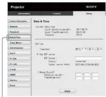
Date & Time button
Current Date Time: Display the current date and time by local time.
Setting: Enter the following items to set the date and time.
-Timezone: Set the time zone. Summer time is unavailable.
-Use NTP server: Select when obtaining the time via a network (NTP server).
-NTP Server: Enter the NTP server.
-Status: Display the connection status to the NTP server.
-latest server data: Display the information last obtained from the NTP server.
Manual(Local): Select when setting the date and time manually.
Date(yyyy-mm-dd): Enter the date.
Time(hh:mm:ss): Enter the time.
Using the Software Update Function
You can update the software of the projector via the network.
The update files can be downloaded from the following Sony website. For details, see "Updating the Software" (page 52).
Note
You can update the software via a network when Power status is in STANDBY.
1 Click on [SW Update] to display the SW Update page.
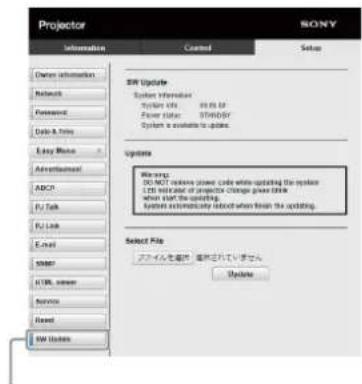
SW Update button
System Info.: Check the software version.
Power status: Check the power source status of the projector.
Select File: Select the file to be updated.
Indicators
You can check the projector status or abnormality by checking the lighting/flashing status of the ON/STANDBY indicator and WARNING indicator on the front. If the indicators flash in red, address the problem in accordance with "Warning indication and remedies" (page 47).
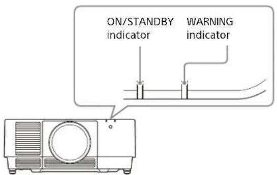
Status indication
| Indicator status Operating status Description | |
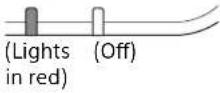 | Standby The power is supplied to the projector and the projector is in a standby mode according to the setting. |
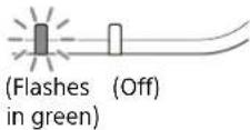 | Warm-up The projector warms up after it is turned on, or the software update is in progress. |
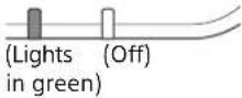 | Ready The projector is ready for projection. |
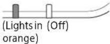 | Other standby status The projector is in With No Input (Light Cutoff), or Quick Reboot standby mode. |
Warning indication and remedies
| Indicator status Number of flashes Meaning/Remedies | |
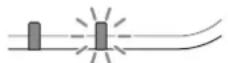 (Lights (Flashes in red) in red) (Lights (Flashes in red) in red) | Twice The filter cover or air filter is not installed securely.Check how the filter cover or air filter is attached and install it securely(page 51). |
| Three times The light source does not light properly.Unplug the AC power cord and make sure the ON/STANDBY indicator turns off, then plug the AC power cord into the wall outlet and turn on the projector. | |
| Four times An error is detected when updating the software of the unit.Unplug the AC power cord and make sure the ON/STANDBY indicator turns off. Check the USB or LAN connection before plugging the AC power cord into the wall outlet and turning on the projector. Then update the software again (page 52). | |
| Six times A strong shock to the projector is detected.If there is no visible abnormality, unplug the AC power cord and make sure the ON/STANDBY indicator turns off, then plug the AC power cord into the wall outlet and turn on the projector. | |
| Eight times The lens is not attached appropriately.Check how the lens is attached and install it securely (page 13). | |
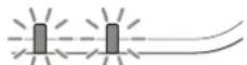 (Flashes (Flashes in red) in red)Both indicators flash (Flashes (Flashes in red) in red)Both indicators flash | Twice The temperature in the projector is abnormal.Perform the following.Check if the air filter is clogged, then clean or replace it (page 51).Check if the ventilation holes (intake/exhaust) are not blocked by the wall or an object and secure a sufficient gap (page 4).Check the ambient temperature and use the projector within the range of operating temperature (page 53). |
If the indicators flash in a manner other than described above, unplug the AC power cord and make sure the ON/STANDBY indicator turns off, then plug the AC power cord into the wall outlet and turn on the projector.
If the problem still persists, consult with qualified Sony personnel.
Messages List
When any of the following messages appears on the projected image, solve the problem as shown in the next table.
| Message Description/Remedy | |
| Clean the filter. | Temperature in the projector has increased. |
| Projector temperature is high. | As a countermeasure against use at an altitude of 1,500 m or higher, set "High Altitude Mode" to "On." |
| Switching to High Altitude Mode. | If you are not using the projector at a high altitude, perform the remedies below and set "High Altitude Mode" to "Auto" (page 34).Check that the air filter is clogged, then clean or replace it (page 51).Check that the ventilation holes (intake/exhaust) are not blocked by a wall or an object and secure a sufficient gap (page 4).Check the ambient temperature and use the projector within the range of operating temperature (page 53). |
| Clean the filter. | Temperature in the projector has increased. |
| Projector temperature is high. The light will turn off in 1 minute. | Perform the remedies below.Check that the air filter is clogged, then clean or replace it (page 51).Check that the ventilation holes (intake/exhaust) are not blocked by a wall or an object and secure a sufficient gap (page 4).Check the ambient temperature and use the projector within the range of operating temperature (page 53). "High Altitude Mode" on this projector is set to "On." Set the setting that suits the operating environment. |
| Frequency is out of range! Change the output setting of the connected device to one for signals supported by the projector (page 57). | |
| Please check Input-A Signal Sel. Set "Input-A Signal Sel." to "Auto" or select the input signal type to suit to the input signal (page 31). | |
| Not applicable! Press the appropriate key on the Remote Commander or control panel (page 6). | |
| The control keys are locked! "Control Key Lock" is set to "On" (page 30). | |
| Lens Control is locked! "Lens Control" is set to "Off" (page 30). | |
| Light Dimming | Reduces light output when "With Static Signal" is set (page 31). When any change in signal is detected, or an operation (Remote Commander or control panel) is performed, normal brightness is restored. |
| Constant Brightness cannot be maintained. | Although "Constant Brightness" is selected, the brightness cannot be maintained due to the lifetime of the light source (page 25). Consult with qualified Sony personnel. |
| Filter cleaning will start. | Turn off the projector and clean the air filter in standby mode (page 34). |
| Tapping sounds will occur. | |
Troubleshooting
Check the following before asking for repair service. If the problem still persists, consult with qualified Sony personnel.
Power
| Symptom Remedy | |
| The power is not turned on. Check if the AC power cord is firmly connected. | |
| When the "Control Key Lock" is set to "On," you cannot turn on the projector using the I/⏻ key on the projector (page 30). | |
| Check how the air filter is attached and install it securely (page 51). | |
Picture
| Symptom Remedy | |
| No image Check if the connecting cable is connected to external device properly(page 8). | |
| Check if the computer signal is set for output to an external monitor. If you set your computer, such as a notebook computer, to output the signal to both your computer's display and an external monitor, an image may not appropriately displayed on the external monitor. Set your computer to output the signal to only an external monitor (page 16). | |
| Check if the input source is correctly selected (page 16). | |
| Check if an image is cut off (page 7). | |
| During "Zone Black Level" adjustment, a black image is automatically projected (page 34). | |
| No image/image disturbance Set "HDMI Cable" to "Long" (page 31). | |
| The color of image has changed. The color calibration may have been performed.To restore the color or the factory default settings, select "Return" or "Reset" in "Color Calibration" (page 29). | |
| Unintended images are output. The color calibration may be being performed.While performing the color calibration, the color calibration pattern is displayed automatically. Wait until the pattern turns off after completing the color calibration.When you press the I/↓ key on the projector or the ↓ key on the Remote Commander, the pattern is turned off and the color calibration function is disabled (page 6, 29). | |
| Flicker in the screen occurs. | Flicker in the screen may occur transiently due to switching signals, but it is not malfunction. |
On-screen display
| Symptom Remedy | |
| On-screen display does not appear. The on-screen display does not appear when “Status” in the Operation menu is set to “Off” or “All Off” (page 30). | |
| The aspect ratio is not correct./An image is displayed smaller./A part of image does not appear. | The image may not be displayed correctly with an input signal the projector cannot interpret correctly. In such a case, set “Aspect” manually (page 27, 28) |
| Check if “Screen Aspect” is correctly selected (page 34). | |
| The image is a trapezoid. The images become trapezoidal because of the projection angle. In such a case, you can correct the trapezoidal distortion, using a Keystone feature (page 6, 18, 33). | |
| Edges of the image are cut off or dark. | If you use the lens shift function over the recommended lens shift range, edges of the image may be cut off or appear dark. Use a setting within the normal range for the lens shift function (page 58). |
| The image is distorted. Warping is set. Disable the warp correction feature (page 19, 33). | |
| The image is dark/too bright. The settings for “Brightness,” “Contrast,” and “Light Output Mode” affect brightness of the image. Check if the value is appropriate (page 24). | |
| “With Static Signal” is set to “On” (page 31). | |
| When video signal is not input, the light is dimmed to reduce power consumption (page 31). | |
| When the temperature around the unit is high, the brightness may be reduced to protect the unit. | |
| The image is not clear. Check if the projector is in focus (page 17). | |
| Noise appears on the image. Check if the connecting cable is connected to external device properly (page 8). | |
Remote Commander
| Symptom Remedy | |
| The Remote Commander does not work. Check that the batteries are installed correctly. | |
| Check that the batteries are not exhausted. | |
| Check if the “ID Mode” of the projector corresponds to that of the Remote Commander (page 7, 30). | |
| Check the setting for “IR Receiver” (page 30). | |
Others
| Symptom Remedy | |
| The fan is noisy. | The sound from the fan is often greater than normal to cool the light source in the following cases (page 25, 34).When “Light Output Mode” is set to “Standard.”When “Location” in “Intelligent Setting” is set to “Entertainment.”The projector is in at high altitude (“High Altitude Mode” is set to “On”)Temperature is very high. |
| Check that the air filter is clogged, then clean or replace it (page 51).Check that the ventilation holes (intake/exhaust) are not blocked by a wall or an object and secure a sufficient gap (page 4). | |
| The network is not available. | The router may not be appropriately set. For details on the settings, refer to the operating instructions or Website of the router, or consult a relevant manufacturer.Check the LAN cable connection. Unplug the AC power cord and wait for a while, then plug the AC power cord into a wall outlet and turn on the projector by using the I (On) key on the control panel. |
Others
Cleaning the Air Filter
When the message that prompts cleaning the air filter appears, clean the air filter.
If the dust cannot be removed from the air filter even after cleaning, replace the air filter with a new one.
For details on a new air filter, consult with qualified Sony personnel.
Caution
If you continue to use the projector even after the message is displayed, dust may accumulate, clogging it. As a result, the temperature may rise inside the unit, leading to a possible malfunction or fire.
1 Turn off the projector and disconnect the AC power cord from a wall outlet.
2 Slide the filter cover downward by pushing its upper corners on both sides to remove the filter cover.
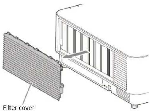
3 Loosen the three screws and pull out the filter holder by pinching the grab on the right side and rotating the filter holder.
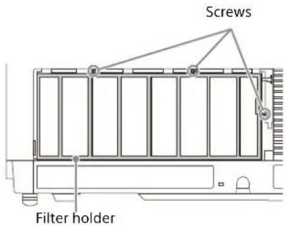
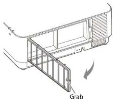
natural_image
Technical line drawing of a mechanical assembly with a labeled 'Grab' component (no other text or symbols)4 Pull out the air filter from the main unit.
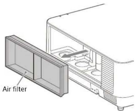
5 Clean the air filter with a vacuum cleaner.
6 Replace the air filter and attach the filter holder.
When attaching the filter holder, first insert the two tabs on the left, insert the three tabs on the right, and tighten the three screws.
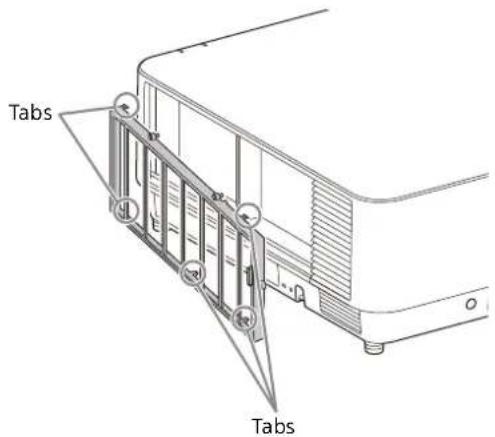
7 Insert the tabs on the filter cover and slide the filter cover upward.
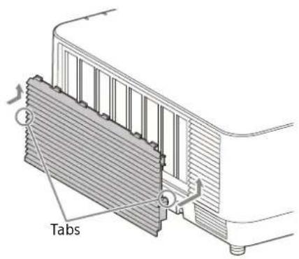
Note
Be sure to attach the air filter firmly; the power cannot be turned on if it is not attached securely.
Updating the Software
Updating the Software via the USB Memory
To update the software of the unit, download files for update to your computer. Copy the downloaded files to your USB memory and insert the USB memory to the USB port of the unit. You are required to prepare a USB memory device, and the environment that your computer can be connected to the Internet and update files can be written on the USB memory.
The update files can be downloaded from the Sony website.
For details, refer to the following website.
https://pro.sony.com
https://www.sony.jp/vpl/ (Access from Japan)
Updating the Software via the Network
To update the software of the unit via the network, connect the computer to the LAN that the projector is connected to.
The update files can be downloaded from the Sony website.
For details, refer to the website or "Using the Software Update Function" on page 45.
https://pro.sony.com
https://www.sony.jp/vpl/ (Access from Japan)
Notes
- USB 2.0 memory device up to 8 GB is available for the projector. However, all the USB memory devices are not guaranteed for use on the projector.
When you format the USB memory, make sure to do so with a FAT32 file system. If you format the USB memory with a file system other than FAT32, you cannot use the USB memory for the projector.
- Some USB memory devices may not be supported. For details, refer to the above website.
- Depending on the environment, it may take about 80 minutes to update.
- Do not unplug the power cable while updating the software.
Specifications
| Item Description | ||
| Display system 3 LCD system | ||
| Display device Size of effective display area | 1.0" (25.4 mm) × 3, Aspect ratio 16:10 | |
| Number of pixels 6,912,000 (1920 × 1200 × 3) pixels | ||
| Light source Laser diode | ||
| Projected image size | 40 inches to 600 inches (1.02 m to 15.24 m) | |
| Light output VPL-FHZ131L: 13,000 lm | *1 (when "Light Output Mode" is set to "Standard")VPL-FHZ101L: 10,000 lm*1 (when "Light Output Mode" is set to "Standard")VPL-FHZ91L: 9,000 lm*1 (when "Light Output Mode" is set to "Standard") | |
| Displayable scanning frequency*2 | Horizontal: 15 kHz to 92 kHz, Vertical: 48 Hz to 92 Hz | |
| Display resolution *2 | Computer signal input | Maximum display resolution: 1920 × 1200 dots |
| Video signal input 480/60i, 576/50i, 480/60p, 576/50p, 720/60p, 720/50p, 1080/60i, 1080/50i, 1080/60p, 1080/50p, 1080/30p, 1080/24p | ||
| Computer and video signal input/output | INPUT A RGB/YP | bPr input terminal: 5BNC female, G with sync/Y: 1 Vp-p ± 2 dB, sync negative, 75 ohms terminated, RGB/PbPR: 0.7 Vp-p ± 2 dB, 75 ohms terminated, Sync signal: TTL level high impedance, positive/negative |
| INPUT B | RGB input terminal: Mini D-sub 15-pin female, RGB: 0.7 Vp-p ± 2 dB, 75 ohms terminated, Sync signal: TTL level high impedance, positive/negative | |
| INPUT C | DVI-D input terminal: DVI-D 24-pin (Single link), DVI 1.0 compliant, HDCP support | |
| INPUT D | HDMI input terminal: HDMI 19-pin, digital RGB/YPbPR, HDCP support | |
| INPUT E HDBaseT terminal: RJ45HDBaseT transmittable signal: HDMI (Video), RS-232C, Ethernet (100BASE-TX)HDBaseT LAN cable: STP cable with CAT5e or higher (straight type) (not supplied), Maximum length: 100 m | ||
| OUTPUT | MONITOR output terminal: Mini D-sub 15-pin female, G with sync/Y: 1 Vp-p ± 2 dB, sync negative, 75 ohms terminated, RGB/PbPR: 0.7 Vp-p ± 2 dB, 75 ohms terminated, Sync signal: HD, VD 4 V (open), 1 Vp-p (75 ohms), positive/negative | |
| Control signal input/output | RS-232C terminal: D-Sub 9 pin male | |
| LAN terminal: RJ45, 10BASE-T/100BASE-TX/1000BASE-T | ||
| Operating temperature | 0°C to 45°C (32 °F to 113 °F) | |
| Operating humidity | 20% to 80% (no condensation) | |
| Storage temperature | -10°C to +60°C (14°F to 140°F) | |
| Storage humidity | 20% to 80% (no condensation) | |
| Power required | VPL-FHZ131L: AC 100 V to 240 V, 10.8 A to 4.4 A, 50/60 HzVPL-FHZ101L: AC 100 V to 240 V, 8.4 A to 3.4 A, 50/60 HzVPL-FHZ91L: AC 100 V to 240 V, 8.4 A to 3.4 A, 50/60 Hz | |
| Power consumption | AC 100 V to 120 V | VPL-FHZ131L: 1,076 WVPL-FHZ101L: 840 WVPL-FHZ91L: 840 W |
| AC 220 V to 240 V | VPL-FHZ131L: 1,033 WVPL-FHZ101L: 814 WVPL-FHZ91L: 814 W | |
| Power consumption (Standby Mode) | AC 100 V to 120 V 0.50 W (when “Standby Mode” is set to “Low”) | |
| AC 220 V to 240 V 0.50 W (when “Standby Mode” is set to “Low”) | ||
| Power consumption (Networked Standby Mode) | AC 100 V to 120 V 21.6 W (LAN), 26.5 W (HDBaseT), 26.6 W (All Terminals and Networks Connected) (when “Standby Mode” is set to “Standard”) | |
| AC 220 V to 240 V 21.3 W (LAN), 26.5 W (HDBaseT), 26.6 W (All Terminals and Networks Connected) (when “Standby Mode” is set to “Standard”) | ||
| Heat dissipation | AC 100 V to 120 V VPL-FHZ131L: 3,671 BTU/hVPL-FHZ101L: 2,866 BTU/hVPL-FHZ91L: 2,866 BTU/h | |
| AC 220 V to 240 V VPL-FHZ131L: 3,524 BTU/hVPL-FHZ101L: 2,777 BTU/hVPL-FHZ91L: 2,777 BTU/h | ||
| Outside dimensions | 544×225×572 mm (21 13/32" × 8 27/32" × 22 17/32") (W/H/D)544×205×564 mm (21 13/32" × 8 1/16" × 22 7/32") (W/H/D) (without protrusions) | |
| Mass VPL-FHZ131L: Approx. 27 kg (58 lb) | ||
| Supplied accessories | See “Checking the Supplied Accessories” in the supplied Quick Reference Manual. | |
*1: When attaching VPLL-Z4019.
*2: For details, refer to "Acceptable Input Signals" on page 57.
Optional accessories
- Not all optional accessories are available in all countries and area. Please check with your local Sony Authorized Dealer.
• Information on accessories in this manual is current as of April 2020. - For details on the optional accessories, refer to their operating instructions.
| Item Description | |
| Projection LensVPLL-4008 | Manual focusProjected image size: 40" to 600" (1.02 m to 15.24 m)Maximum external dimensions (W×H×D): 148×133×240 mm(5 13/16"×5 1/4"×9 7/16")Mass: Approx. 2.6 kg (5.6 lb) |
| Projection LensVPLL-Z4111 | Electric focus/zoomPicture Position supported-lensProjected image size: 60" to 600" (1.52 m to 15.24 m)Maximum external dimensions (W×H×D): 158×150×263 mm(6 7/32"×5 29/32"×10 11/32")Mass: Approx. 4.0 kg (8.8 lb) |
| Projection LensVPLL-Z4015 | Electric focus/zoomProjected image size: 40" to 600" (1.02 m to 15.24 m)Maximum external dimensions (W×H×D): 148×133×231 mm(5 13/16"×5 1/4"×9 3/32")Mass: Approx. 3.0 kg (6.6 lb) |
| Projection LensVPLL-Z4019 | Electric focus/zoomProjected image size: 40" to 600" (1.02 m to 15.24 m)Maximum external dimensions (W×H×D): 148×133×212 mm(5 13/16"×5 1/4"×8 11/32")Mass: Approx. 3.0 kg (6.6 lb) |
| Projection LensVPLL-Z4025 | Electric focus/zoomProjected image size: 40" to 600" (1.02 m to 15.24 m)Maximum external dimensions (W×H×D): 148×133×243 mm(5 13/16"×5 1/4"×9 9/16")Mass: Approx. 2.8 kg (6.2 lb) |
| Projection LensVPLL-Z4045 | Electric focus/zoomProjected image size: 60" to 600" (1.52 m to 15.24 m)Maximum external dimensions (W×H×D): 148×133×235 mm(5 13/16"×5 1/4"×9 1/4")Mass: Approx. 3.0 kg (6.6 lb) |
| Projection LensVPLL-Z4107 | Electric focus/zoomProjected image size: 60" to 600" (1.52 m to 15.24 m)Maximum external dimensions (W×H×D): 158 × 143 × 266 mm (6 7/32" × 5 5/8" × 10 15/32")Mass: Approx. 3.3 kg (7.2 lb) |
| 3G-SDI INPUT AdaptorBKM-PJ20 | For details, refer to the operating instructions of BKM-PJ20. |
Note
The values for mass and dimensions are approximate.
Design and specifications of the unit, including the optional accessories, are subject to change without notice.
Pin assignment
DVI-D terminal (DVI-D, female)
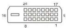
| 1 T.M.D.S. Data2- 14 +5 V Power | |||||
| 2 T.M.D.S. Data2+ 15 Ground (return for +5 V) | |||||
| 3 T.M.D.S. Data2 Shield 16 Hot Plug Detect | |||||
| 4 NC 17 T.M.D.S. Data0- | |||||
| 5 NC 18 T.M.D.S. Data0+ | |||||
| 6 DDC Clock 19 T.M.D.S. Data0 Shield | |||||
| 7 DDC Data 20 NC | |||||
| 8 | N | C | 2 | 1 | N |
| 9 T.M.D.S. Data1- | 22 | T.M.D.S. Clock Shield | |||
| 10 T.M.D.S. Data1+ | 23 | T.M.D.S. Clock+ | |||
| 11 | T.M.D.S. Data1 Shield 24 | T.M.D.S. Clock- | |||
| 12 NC | |||||
| 13 | NC | ||||
RGB input terminal (Mini D-sub 15-pin, female)
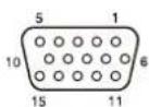
| 1 Video input (red) R 9 Power supply input for DDC | |||
| 2 Video input (green) G 10 GND | |||
| 3 Video input (blue) B 11 GND | |||
| 4 G N D | 1 2 D D C | ||
| 5 RESERVE 13 Horizontal sync signal | |||
| 6 GND (R) 14 Vertical sync signal | |||
| 7 GND (G) 15 DDC/SCL | |||
| 8 G N D ( B ) | |||
RS-232C terminal (D-Sub 9-pin, male)
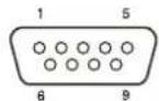
| 1 | NC | 6 | NC |
| 2 | RXDA | 7 | RTS |
| 3 | TXDA | 8 | CTS |
| 4 | D T R | 9 N C | |
| 5 | GN D |
HDMI terminal (HDMI, female)

| 1 T.M.D.S. Data2+ 11 T.M.D. | S. Clock Shield |
| 2 T.M.D.S. Data2 Shield 12 | T.M.D.S. Clock- |
| 3 T.M.D.S. Data2- 13 NC | |
| 4 T.M.D.S. Data1+ | 14 RESERVED (N.C.) |
| 5 T.M.D.S. Data1 Shield 15 | SCL |
| 6 T.M.D.S. Data1- | 16 SDA |
| 7 T.M.D.S. Data0+ | 17 GND |
| 8 T.M.D.S. Data0 Shield | 18 +5V Power |
| 9 T.M.D.S. Data0- | 19 Hot Plug Detect |
| 10 T.M.D.S. Clock+ |
/ S DA
Acceptable Input Signals
Computer signal
| Resolution | fH [kHz]/fV [Hz] | Input terminal | |
| INPUT A/INPUT B | INPUT C/INPUT D/INPUT E | ||
| 640 × 350 31.5 | /70 | ● | - |
| 37.9/85 | ● | - | |
| 640 × 400 31.5 | /70 | ● | - |
| 37.9/85 | ● | - | |
| 640 × 480 31.5 | /60 | ● | ● |
| 35.0/67 | ● | - | |
| 37.9/73 | ● | - | |
| 37.5/75 | ● | - | |
| 43.3/85 | ● | - | |
| 800 × 600 35.2 | /56 | ● | - |
| 37.9/60 | ● | ● | |
| 48.1/72 | ● | - | |
| 46.9/75 | ● | - | |
| 53.7/85 | ● | - | |
| 832 × 624 49.7 | /75 | ● | - |
| 1024 × 768 48 | 4/60 | ● | ● |
| 56.5/70 | ● | - | |
| 60.0/75 | ● | - | |
| 68.7/85 | ● | - | |
| 1152 × 864 64.0 | /70 | ● | - |
| 67.5/75 | ● | - | |
| 77.5/85 | ● | - | |
| 1152 × 900 61.8 | /66 | ● | - |
| 1280 × 960 60.0 | /60 | ● | ● |
| 75.0/75 | ● | - | |
| 1280 × 1024 64.0 | /60 | ● | ● |
| 80.0/75 | ● | - | |
| 91.1/85 | ● | - | |
| 1400 × 1050 65.3 | /60 | ● | ● |
| 1600 × 1200 75.0 | /60 | ● | ● |
| 1280 × 768 | 47.8/60 | ● | ● |
| 1280 × 720 45.0 | /60 | ● | ●*1 |
| 1920 × 1080 | 67.5/60 | - | ●*1 |
| 1366 × 768 47.7 | /60 | ● | ● |
| 1440 × 900 55.9 | /60 | ● | ● |
| 1680 × 1050 65.3 | /60 | ● | ● |
| 1280 × 800 | 49.7/60 | ● | ● |
| 1920 × 1200 | 74.0/60 | ●*2 | ●*2 |
| 1600 × 900 | 60.0/60 | ●*2 | ●*2 |
Video signal
| Signal | fV [Hz] | Input terminal | ||
| INPUT A/ INPUT B | INPUT C/ INPUT D/ INPUT E | INPUT^ 3 | ||
| 480i | 60 | ● | ● | ● |
| 576i | 50 | ● | ● | ● |
| 480p | 60 | ● | ● | - |
| 576p | 50 | ● | ● | - |
| 1080i | 60 | ● | ● | ● |
| 1080i | 50 | ● | ● | ● |
| 720p | 60 | ● | ●*1 | ● |
| 720p | 50 | ● | ● | ● |
| 1080p 60 | - | ● | *1 | ● |
| 1080p 50 | - | ● | ● | |
| 1080p | 30 | - | - | ● |
| 1080p | 24 | - | ● | ● |
*1: INPUT C is determined as a computer signal; INPUT D/INPUT E is determined as a video signal.
*2: Available for VESA Reduced Blanking signal only.
*3: Available for BKM-PJ20 only.
Notes
- When you input a signal other than the signals listed in the table, the picture may not be displayed appropriately.
- An input signal meant for screen resolution different from that of the panel will not be displayed in its original resolution. Text and lines may be uneven.
- Some actual value may differ slightly from the design values given in the table.
Projection Distance and Lens Shift Range
Projection distance
The projection distance refers to the distance between the front of the lens and the projected surface.
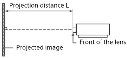
Unit: m (inches)
| Projection image size Projection distance L | ||||||||
| Diagonal | Width × Height | VPLL-4008 | VPLL-Z4111 | VPLL-Z4015 | VPLL-Z4019 | VPLL-Z4025 | VPLL-Z4045 | VPLL-Z4107 |
| 80" (2.03 m) | 72×1.08(68×42) | 1.70(67) | 2.23 - 3.36(88 - 132) | 3.06 - 4.24(121 - 167) | 4.04 - 5.37(159 - 211) | 4.99 - 9.78(197 - 385) | 9.33 - 12.92(368 - 508) | 1.29 - 1.59(51 - 62) |
| 100" (2.54 m) | 2.15×1.35(85×53) | 2.14(84) | 2.81 - 4.22(111 - 166) | 3.85 - 5.33(152 - 209) | 5.08 - 6.74(200 - 265) | 6.27 - 12.27(247 - 483) | 11.71 - 16.15(461 - 635) | 1.63 - 2.00(64 - 78) |
| 120" (3.05 m) | 2.58×1.62(102×64) | 2.58(102) | 3.38 - 5.08(133 - 200) | 4.65 - 6.41(183 - 252) | 6.12 - 8.12(241 - 319) | 7.56 - 14.75(298 - 580) | 14.10 - 19.38(555 - 763) | 1.96 - 2.41(77 - 94) |
| 150" (3.81 m) | 3.23×2.02(127×79) | 3.25(128) | 4.24 - 6.37(167 - 250) | 5.83 - 8.04(230 - 316) | 7.68 - 10.18(303 - 400) | 9.49 - 18.48(374 - 727) | 17.67 - 24.23(696 - 953) | 2.46 - 3.02(97 - 119) |
| 200" (5.08 m) | 4.31×2.69(170×106) | 4.36(172) | 5.68 - 8.52(224 - 335) | 7.81 - 10.76(308 - 423) | 10.28 - 13.61(405 - 536) | 12.70 - 24.69(500 - 972) | 23.63 - 32.30(931 - 1,271) | 3.29 - 4.04(130 - 159) |
Projection distance formula
D: Projection image size (")
Example) Enter 80 in D for the 80" projection image size. Unit: m (inches)
| Lens | Projection distance L (minimal length) | Projection distance L (maximal length) |
| VPLL-4008 L=0.022186xD-0.0777(L=0.873473xD-3.0591) | L=0.000000xD+0.0000(L=0.000000xD+0.0000) | |
| VPLL-Z4111 L=0.028726xD-0.0718(L=1.130955xD-2.8266) | L=0.042976xD-0.0712(L=1.691987xD-2.8024) | |
| VPLL-Z4015 L=0.039555xD-0.1063(L=1.557266xD-4.1850) | L=0.054349xD-0.1045(L=2.139713xD-4.1142) | |
| VPLL-Z4019 L=0.052005xD-0.1235(L=2.047436xD-4.8622) | L=0.068702xD-0.1224(L=2.704809xD-4.8189) | |
| VPLL-Z4025 | L=0.064245xD-0.1553(L=2.529325xD-6.1142) | L=0.124243xD-0.1541(L=4.891449xD-6.0669) |
| VPLL-Z4045 | L=0.119195xD-0.2113(L=4.692699xD-8.3189) | L=0.161544xD0.0000(L=6.359987xD0.0000) |
| VPLL-Z4107 | L=0.016620xD-0.0417(L=0.654341xD-1.6435) | L=0.020437xD-0.0404(L=0.804612xD-1.5916) |
Lens shift range
The lens shift range represents the distance in percent (%) by which the lens can be shifted from the center of the projected image. The lens shift range is regarded as 0% when the point (A) in the illustration (point where a line drawn from the center of the lens and the projected image cross at right angles) is aligned with the center of the projected image and full width or full height of the projected image is regarded as 100%.
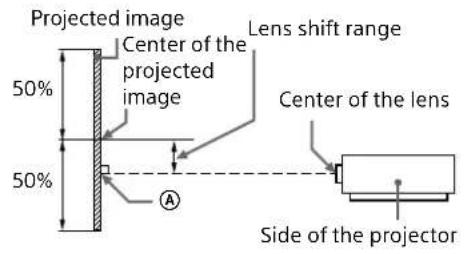
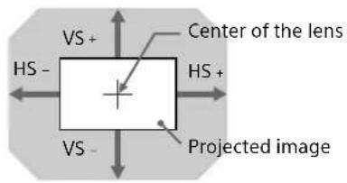
Shaded region: Lens shift range
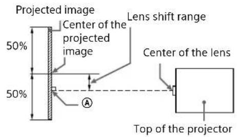
VS +: Vertical lens shift range (up) [%]
VS -: Vertical lens shift range (down) [%]
HS+: Horizontal lens shift range (right) [%]
HS-: Horizontal lens shift range (left) [%]
VPLL-4008
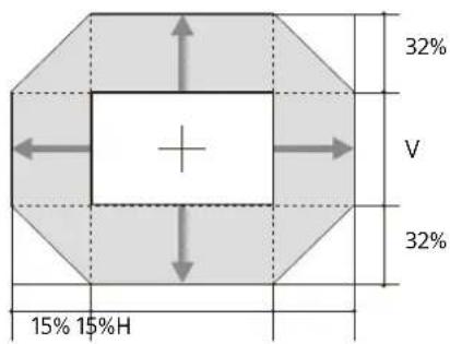
$$ \begin{array}{l} \mathrm{VS} + = 32 - 2.133 \times (\mathrm{HS} + \text { or } \mathrm{HS} -) [\% ] \ \mathrm{VS} _ {-} = 32 - 2.133 \times (\mathrm{HS} + \text { or } \mathrm{HS} _ {-}) [\% ] \ H S + = H S - = 1 5 - 0. 4 6 9 \times V S + [ \% ] \ H S + = H S - = 1 5 - 0. 4 6 9 \times V S - [ \% ] \ \end{array} $$
VPLL-Z4111
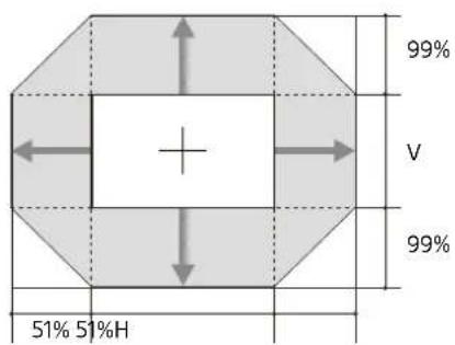
$$ \mathrm{VS} + = 9 9 - 1. 9 4 1 \times (\mathrm{HS} + \text { or } \mathrm{HS} -) [ \% ] $$
$$ V S = 9 9 - 1. 9 4 1 \times (H S + o r H S -) [ \% ] $$
$$ H S + = H S - = 5 1 - 0. 5 1 5 \times V S + [ \% ] $$
$$ H S + = H S - = 5 1 - 0. 5 1 5 \times V S - [ \% ] $$
VPLL-Z4015
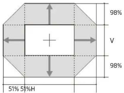
$$ \begin{array}{l} \mathrm{VS} + = 98 - 1.922 \times (\mathrm{HS} + \text { or } \mathrm{HS} -) [\% ] \ \mathrm{VS} - = 98 - 1.922 \times (\mathrm{HS} + \text { or } \mathrm{HS} -) [\% ] \ \mathrm{HS} + = \mathrm{HS} - = 51 - 0.520 \times \mathrm{VS} + [\% ] \ \mathrm{HS} + = \mathrm{HS} - = 51 - 0.520 \times \mathrm{VS} - [\% ] \ \end{array} $$
■ VPLL-Z4019/VPLL-Z4025/VPLL-Z4045
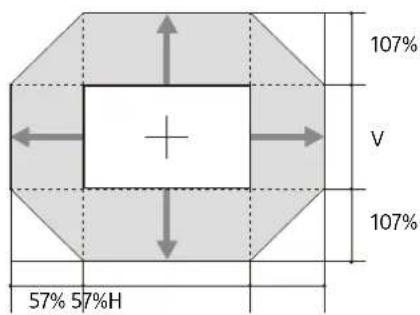
$$ \mathrm{VS} + = 107 - 1.877 \times (\mathrm{HS} + \text { or } \mathrm{HS} -) [\% ] $$
$$ \mathrm{VS} - = 107 - 1.877 \times (\mathrm{HS} + \text { or } \mathrm{HS} -) [\% ] $$
$$ H S + = H S - = 5 7 - 0. 5 3 3 \times V S + [ \% ] $$
$$ \mathrm{HS} + = \mathrm{HS} - = 57 - 0.533 \times \mathrm{VS} - [\% ] $$
VPLL-Z4107
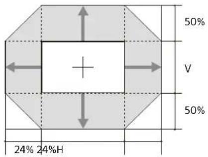
$$ \mathrm{VS} + = 50 - 2.083 \times (\mathrm{HS} + \text { or } \mathrm{HS} -) [\% ] $$
$$ V S - = 5 0 - 2. 0 8 3 \times (H S + o r H S -) [ \% ] $$
$$ \mathrm{HS} + = \mathrm{HS} - = 24 - 0.480 \times \mathrm{VS} + [\% ] $$
$$ \mathrm{HS} + = \mathrm{HS} - = 24 - 0.480 \times \mathrm{VS} - [\% ] $$
Dimensions
Front Unit: mm (inches)
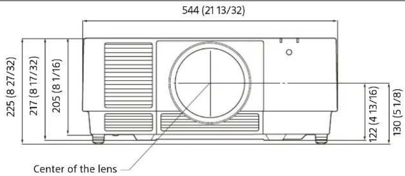
Bottom Unit: mm (inches)
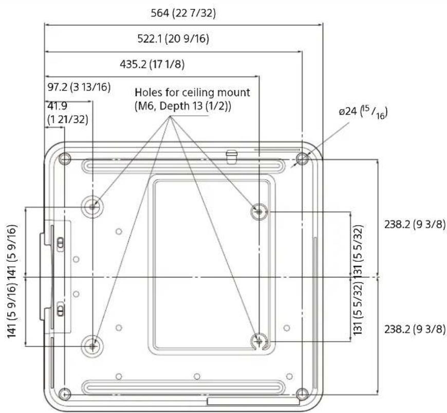
Holes for the ceiling mount
Use the screws with a length of 6.5 mm (1/4 inch, minimum) to 13 mm (1/2 inch, maximum) for the ceiling mount.
Recommended tightening torque (tension when turning a screw towards the direction of rotation): 1.4 ± 0.2 N-m
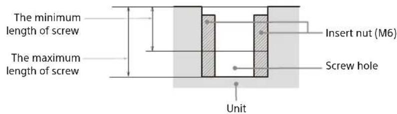
About Trademarks
- Adobe Acrobat is a trademark of Adobe Systems Incorporated.
- Kensington is a registered trademark of Kensington Technology Group.
- Internet Explorer is a registered trademark of Microsoft Corporation in the United States and/or other countries.
- Safari is a registered trademark of Apple Corporation in the United States and/or other countries.
• Chrome is a trademark of Google LLC. - PJLink is a registered trademark of Japan Business Machine and Information System Industries Association.
• AMX is a trademark of AMX Corporation. - The terms HDMI and HDMI High-Definition Multimedia Interface, and the HDMI Logo are trademarks or registered trademarks of HDMI Licensing Administrator, Inc. in the United States and other countries.
- Crestron RoomView is a trademark of Crestron Corporation.
- HDBaseT™ and the HDBaseT Alliance logo are trademarks of the HDBaseT Alliance.
- Extron and XTP Systems are trademarks of RGB Systems, Inc.
- All other trademarks and registered trademarks are trademarks or registered trademarks of their respective holders. In this manual, ^TM and ^ marks are not specified.
NOTICES AND LICENSES FOR SOFTWARE USED IN THIS PRODUCT
Refer to "Software License Information" supplied separately.