
XPS One - Desktop computer DELL - Free user manual and instructions
Find the device manual for free XPS One DELL in PDF.


User questions about XPS One DELL
0 question about this device. Answer the ones you know or ask your own.
Ask a new question about this device
Download the instructions for your Desktop computer in PDF format for free! Find your manual XPS One - DELL and take your electronic device back in hand. On this page are published all the documents necessary for the use of your device. XPS One by DELL.
USER MANUAL XPS One DELL
Regulatory model: W06C | Regulatory type: W06C001
Notes, Cautions, and Warnings

NOTE: A NOTE indicates important information that helps you make better use of your computer.

CAUTION: A CAUTION indicates potential damage to hardware or loss of data if instructions are not followed.

WARNING: A WARNING indicates a potential for property damage, personal injury, or death.
Information in this document is subject to change without notice.
© 2012 Dell Inc. All rights reserved.
Reproduction of these materials in any manner whatsoever without the written permission of Dell Inc. is strictly forbidden.
Trademarks used in this text: Dell™, the DELL logo, and XPS One™ are trademarks of Dell Inc.; Microsoft®, Windows®, and the Windows start button logo are either trademarks or registered trademarks of Microsoft Corporation in the United States and/or other countries; Bluetooth® is a registered trademark owned by Bluetooth SIG, Inc. and is used by Dell under license. Intel® is a registered trademark and Intel SpeedStep™ is a trademark of Intel Corporation in the U.S. and/or other countries.
Other trademarks and trade names may be used in this document to refer to either the entities claiming the marks and names or their products. Dell Inc. disclaims any proprietary interest in trademarks and trade names other than its own.
1 Before You Begin 11
Turn Off Your Computer and Connected Devices . . 11
Recommended Tools.... 11
Safety Instructions.... 12
2 After Working Inside Your Computer. . . . . . 13
3 Technical Overview 15
Inside View of Your Computer.... 15
System-Board Components 16
4 Removing the Back Cover 19
Procedure 19
5 Replacing the Back Cover 21
Procedure 21
6 Removing the Converter Board 23
Prerequisites. 23
Procedure 23
7 Replacing the Converter Board 25
Procedure 25
Postrequisites.... 25
8 Removing the Optical Drive 27
Prerequisites. 27
Procedure 27
9 Replacing the Optical Drive 29
Procedure 29
Postrequisites....29
10 Removing the System-Board Shield. . . . . . . 31
Prerequisites.... 31
Procedure 31
11 Replacing the System-Board Shield ..... 33
Procedure 33
Postrequisites 33
12 Removing the Power-Supply Unit 35
Prerequisites.... 35
Procedure 35
13 Replacing the Power-Supply Unit 37
Procedure 37
Postrequisites 37
14 Removing the Memory Module(s)....39
Prerequisites.... 39
Procedure 39
15 Replacing the Memory Module(s)....41
Procedure 41
Postrequisites 41
16 Removing the Coin-Cell Battery.... 43
Prerequisites.... 43
Procedure 43
17 Replacing the Coin-Cell Battery 45
Procedure 45
Postrequisites 45
18 Removing the Stand. 47
Prerequisites.... 47
Procedure 47
19 Replacing the Stand. 49
Procedure 49
Postrequisites 49
20 Removing the Hard Drive 51
Prerequisites.... 51
Procedure 51
21 Replacing the Hard Drive 53
Procedure 53
Postrequisites 53
22 Removing the Hard-Drive Cage 55
Prerequisites.... 55
Procedure 55
23 Replacing the Hard-Drive Cage 57
Procedure 57
Postrequisites 57
24 Removing the Power-Supply Fan 59
Prerequisites.... 59
Procedure 59
25 Replacing the Power-Supply Fan 61
Procedure 61
Postrequisites 61
26 Removing the TV-Tuner Mini-Card ..... 63
Prerequisites.... 63
Procedure 63
27 Replacing the TV-Tuner Mini-Card 65
Procedure 65
Postrequisites 65
28 Removing the Wireless Mini-Card 67
Prerequisites.... 67
Procedure 67
29 Replacing the Wireless Mini-Card ..... 69
Procedure 69
Postrequisites 69
30 Removing the mSATA Mini-Card 71
Prerequisites....71
Procedure 71
31 Replacing the mSATA Mini-Card....73
Procedure 73
Postrequisites 73
32 Removing the Processor Heat-Sink Fan. . . . 75
Prerequisites.... 75
Procedure 75
33 Replacing the Processor Heat-Sink Fan....77
Procedure 77
Postrequisites 77
34 Removing the Processor Heat-Sink ..... 79
Prerequisites....79
Procedure 79
35 Replacing the Processor Heat-Sink 81
Procedure 81
Postrequisites 81
36 Removing the Processor 83
Prerequisites.... 83
Procedure 83
37 Replacing the Processor 85
Procedure 85
Postrequisites 86
38 Removing the Trim Cover 87
Prerequisites.... 87
Procedure 87
39 Replacing the Trim Cover 89
Procedure 89
Postrequisites 89
40 Removing the I/O Panel 91
Prerequisites.... 91
Procedure 91
41 Replacing the I/O Panel....93
Procedure 93
Postrequisites 93
42 Removing the Inner Frame 95
Prerequisites.... 95
Procedure 95
43 Replacing the Inner Frame 97
Procedure 97
Postrequisites 97
44 Removing the I/O-Board 99
Prerequisites.... 99
Procedure 99
45 Replacing the I/O Board 101
Procedure 101
Postrequisites 101
46 Removing the TV-In Port. 103
Prerequisites.... 103
Procedure 103
47 Replacing the TV-In Port.... 105
Procedure 105
Postrequisites 105
48 Removing the Infrared-Emitter Port ..... 107
Prerequisites.... 107
Procedure 108
49 Replacing the Infrared-Emitter Port. ..... 109
Procedure 109
Postrequisites 109
50 Removing the System Board.... 111
Prerequisites.... 111
Procedure 112
51 Replacing the System Board 113
Procedure 113
Postrequisites 114
Entering the Service Tag in system setup ..... 114
52 Removing the Speakers.... 115
Prerequisites.... 115
Procedure 115
53 Replacing the Speakers 117
Procedure 117
Postrequisites 117
54 Removing the Power-Button Assembly . . . 119
Prerequisites.... 119
Procedure 119
55 Replacing the Power-Button Assembly . . . 121
Procedure 121
Postrequisites 121
56 Removing the Side I/O-Board....123
Prerequisites.... 123
Procedure 124
57 Replacing the Side-I/O Board 125
Procedure 125
Postrequisites 125
58 Removing the Middle Cover 127
Prerequisites.... 127
Procedure 128
59 Replacing the Middle Cover 131
Procedure 131
Postrequisites 132
60 Removing the Display Panel 133
Prerequisites.... 133
Procedure 133
61 Replacing the Display Panel 139
Procedure 139
Postrequisites 140
62 Removing the Camera Module 141
Prerequisites.... 141
Procedure 142
63 Replacing the Camera Module 143
Procedure 143
Postrequisites 143
64 Removing the Microphone Modules ..... 145
Prerequisites.... 145
Procedure 146
65 Replacing the Microphone Modules ..... 147
Procedure 147
Postrequisites 147
66 Removing the Infrared (IR) Module ..... 149
Prerequisites.... 149
Procedure 150
67 Replacing the Infrared (IR) Module ..... 151
Procedure 151
Postrequisites 151
68 Removing the Antenna Module(s) 153
Prerequisites.... 153
Procedure 154
69 Replacing the Antenna Module(s)....155
Procedure 155
Postrequisites 155
70 System Setup 157
Overview 157
Entering System Setup 157
Changing Boot Sequence 162
Clearing Forgotten Passwords ..... 163
Clearing CMOS Settings 164
71 Flashing the BIOS.... 165
Turn Off Your Computer and Connected Devices

CAUTION: To avoid losing data, save and close all open files and exit all open programs before you turn off your computer.
1 Save and close all open files and exit all open programs.
2 Click Start and click Shut Down.
Microsoft Windows shuts down and then the computer turns off.

NOTE: If you are using a different operating system, see the documentation of your operating system for shut-down instructions.
3 Disconnect your computer and all attached devices from their electrical outlets.
4 Disconnect all telephone cables, network cables, and attached devices from your computer.
5 After the computer is unplugged, press and hold the power button for about 5 seconds to ground the system board.
Recommended Tools
The procedures in this document may require the following tools:
• Phillips screwdriver
- Plastic scribe
Safety Instructions
Use the following safety guidelines to protect your computer from potential damage and ensure your personal safety.

WARNING: Before working inside your computer, read the safety information that shipped with your computer. For additional safety best practices information, see the Regulatory Compliance Homepage at dell.com/regulatory_compliance.

WARNING: Disconnect all power sources before opening the computer cover or panels. After you finish working inside the computer, replace all covers, panels, and screws before connecting to the power source.

CAUTION: To disconnect a network cable, first unplug the cable from your computer and then unplug the cable from the network device.

CAUTION: To avoid damaging the computer, ensure that the work surface is flat and clean.

CAUTION: To avoid damaging the components and cards, handle them by their edges and avoid touching pins and contacts.

CAUTION: Only a certified service technician is authorized to remove the computer cover and access any of the components inside the computer. See the safety instructions for complete information about safety precautions, working inside your computer, and protecting against electrostatic discharge.

CAUTION: Before touching anything inside your computer, ground yourself by touching an unpainted metal surface, such as the metal at the back of the computer. While you work, periodically touch an unpainted metal surface to dissipate static electricity, which could harm internal components.

CAUTION: When you disconnect a cable, pull on its connector or on its pull-tab, not on the cable itself. Some cables have connectors with locking tabs or thumb-screws that you must disengage before disconnecting the cable. When disconnecting cables, keep them evenly aligned to avoid bending any connector pins. When connecting cables, ensure that the connectors and ports are correctly oriented and aligned.
2
After Working Inside Your Computer
After you complete the replacement procedures, ensure the following:
- Replace all screws and ensure that no stray screws remain inside your computer
- Connect any external devices, cables, cards, and any other part(s) you removed before working on your computer
- Connect your computer and all attached devices to their electrical outlets

CAUTION: Before turning on your computer, replace all screws and ensure that no stray screws remain inside the computer. Failure to do so may damage your computer.

WARNING: Before working inside your computer, read the safety information that shipped with your computer and follow the steps in "Before You Begin" on page 11. After working inside your computer, follow the instructions in "After Working Inside Your Computer" on page 13. For additional safety best practices information, see the Regulatory Compliance Homepage at dell.com/regulatory_compliance.
Inside View of Your Computer
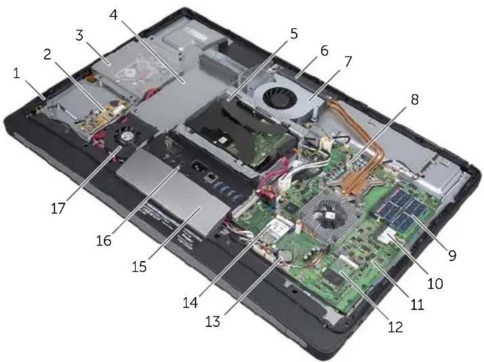
text_image
Labeled diagram of a smartphone showing internal components with numbered parts for identification.| 1 power-button assembly 2 converter board | |||
| 3 optical-drive assembly 4 power-supply unit | |||
| 5 hard-drive assembly 6 cooling vents | |||
| 7 processor heat-sink fan 8 processor heat-sink | |||
| 9 memory module(s) 10 wireless mini-card | |||
| 11 system board | 12 | mSATA mini-card | |
| 13 coin-cell battery | 14 | TV-tuner card | |
| 15 trim cover | 16 | I/O panel | |
| 17 power-supply fan | 18 | ||
System-Board Components
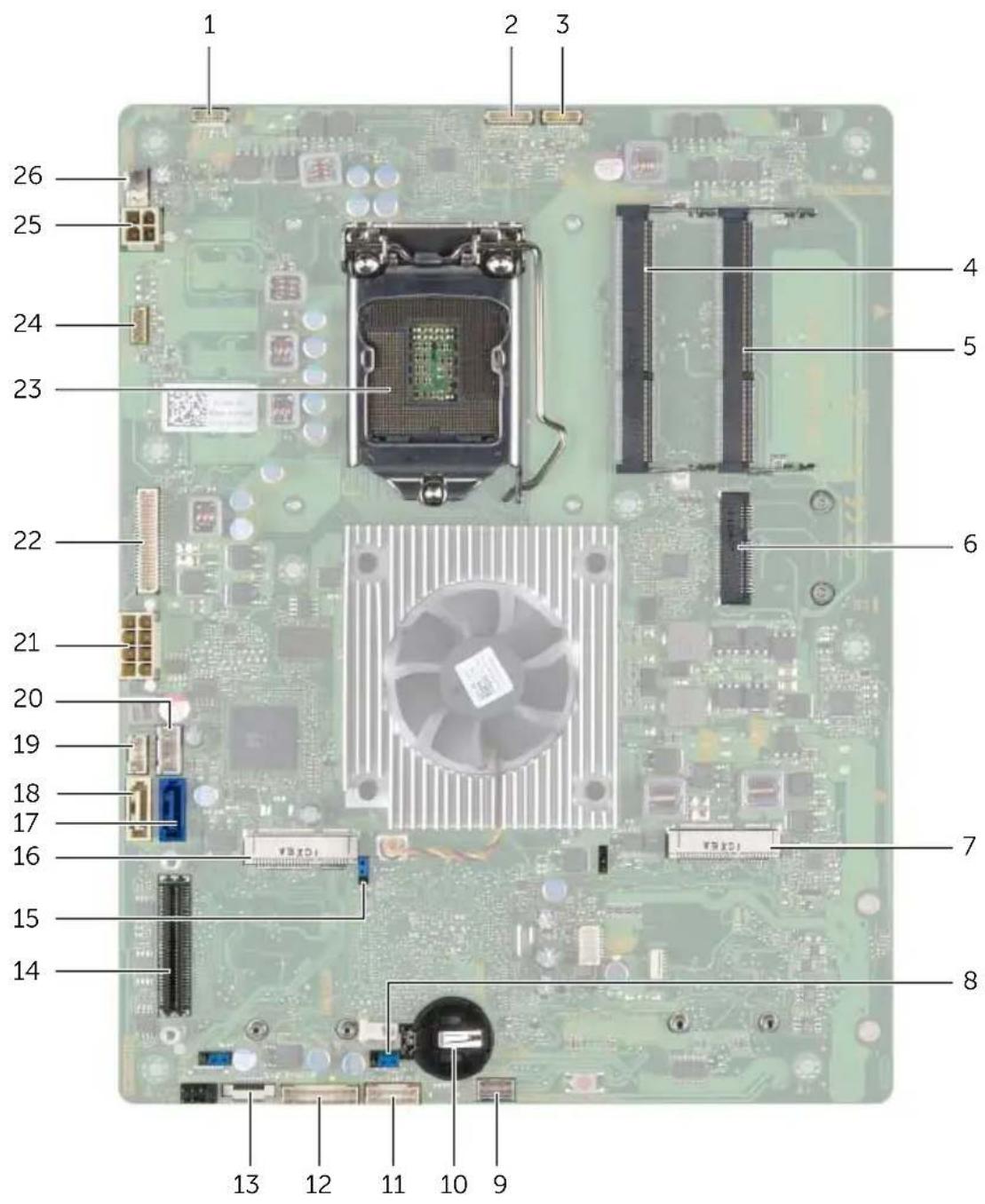
text_image
1 2 3 26 25 24 23 22 21 20 19 18 17 16 15 14 13 12 11 10 9 4 5 6 7 8| 1 display-power cable connector 2 camera-cable connector | |||
| 3 | Infrared-module cable connector | 4 | memory-module connector (DIMM 1) |
| 5 | memory-module connector (DIMM 2) 6 wireless mini-card connector | ||
| 7 | mSATA mini-card connector 8 CMOS jumper | ||
| 9 | speaker-cable connector 10 coin-cell battery socket | ||
| 11 | power-button cable connector | 12 | converter-board cable connector |
| 13 | volume/display-settings controls cable connector | 14 | I/O-board connector |
| 15 password jumper 16 TV-tuner mini-card connector |
| 17 hard-drive data-cable connector 18 optical-drive data-cable connector |
| 19 optical-drive power-cable connector 20 hard-drive power-cable connector |
| 21 main (8-pin) power-cable connector 22 LVDS-cable connector |
| 23 processor socket 24 touchscreen-cable connector |
| 25 processor (4-pin) power-cable connector 26 processor heat-sink fan-cable connector |
4
Removing the Back Cover

WARNING: Before working inside your computer, read the safety information that shipped with your computer and follow the steps in "Before You Begin" on page 11. After working inside your computer, follow the instructions in "After Working Inside Your Computer" on page 13. For additional safety best practices information, see the Regulatory Compliance Homepage at dell.com/regulatory_compliance.
Procedure
1 Place the computer face-down on a clean and flat surface.
2 Loosen the captive screws that secure the back cover to the inner frame.
3 Slide the back cover toward the top of the computer and lift the back cover off the computer base.
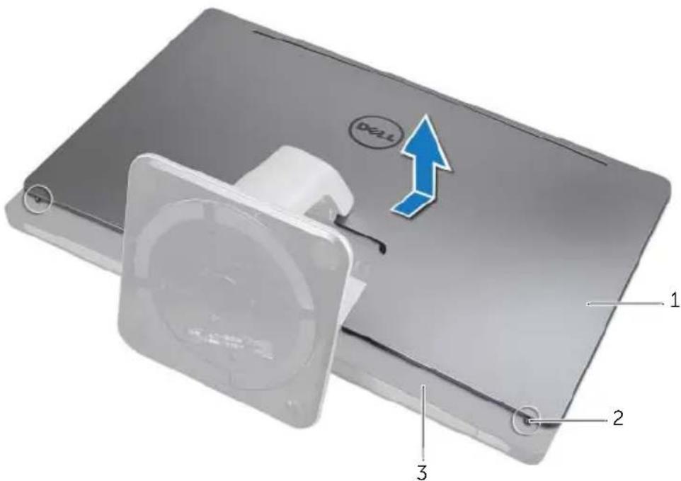
text_image
DELL 1 2 31 back cover 2 captive screws (2)
3 i n n e r f r a m e

WARNING: Before working inside your computer, read the safety information that shipped with your computer and follow the steps in "Before You Begin" on page 11. After working inside your computer, follow the instructions in "After Working Inside Your Computer" on page 13. For additional safety best practices information, see the Regulatory Compliance Homepage at dell.com/regulatory_compliance.
Procedure
1 Place the back cover over the inner frame and slide the back cover toward the bottom of the computer.
2 Tighten the captive screws that secure the back cover to the inner frame.

WARNING: Before working inside your computer, read the safety information that shipped with your computer and follow the steps in "Before You Begin" on page 11. After working inside your computer, follow the instructions in "After Working Inside Your Computer" on page 13. For additional safety best practices information, see the Regulatory Compliance Homepage at dell.com/regulatory_compliance.
Prerequisites
1 Remove the back cover. See "Removing the Back Cover" on page 19.
Procedure
1 Lift the securing tab on the display-backlight cable connector and then disconnect the display-backlight cable from the convertor board.
2 Disconnect the converter cable from the converter board.
3 Remove the screws that secure the converter board to the computer base.
4 Lift the converter board off the computer base.
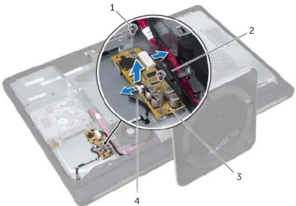
text_image
Laptop interior with labeled components and a magnified view showing internal circuit board connections1 screws (2) 2 converter cable
3 converter board 4 display-backlight cable

WARNING: Before working inside your computer, read the safety information that shipped with your computer and follow the steps in "Before You Begin" on page 11. After working inside your computer, follow the instructions in "After Working Inside Your Computer" on page 13. For additional safety best practices information, see the Regulatory Compliance Homepage at dell.com/regulatory_compliance.
Procedure
1 Align the screw holes on the converter board with the screw holes on the computer base.
2 Replace the screws that secure the converter board to the computer base.
3 Connect the converter cable to the converter board.
4 Connect the display-backlight cable to the convertor board and secure the tab.
Postrequisites
1 Replace the back cover. See "Replacing the Back Cover" on page 21.

WARNING: Before working inside your computer, read the safety information that shipped with your computer and follow the steps in "Before You Begin" on page 11. After working inside your computer, follow the instructions in "After Working Inside Your Computer" on page 13. For additional safety best practices information, see the Regulatory Compliance Homepage at dell.com/regulatory_compliance.
Prerequisites
1 Remove the back cover. See "Removing the Back Cover" on page 19.
Procedure
1 Remove the screws that secure the optical-drive assembly to the computer base.
2 Gently lift the optical-drive assembly from the computer base and disconnect the power and data-cable connector from the optical-drive assembly.
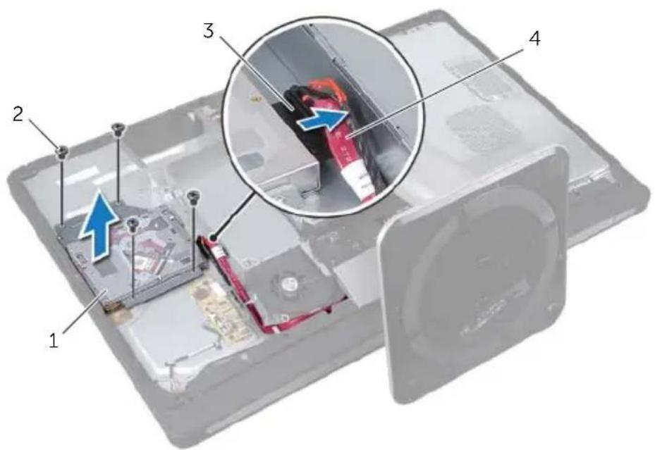
text_image
Labeled diagram of a computer case showing internal components and a magnified view with numbered parts1 optical-drive assembly 2 screws (4)
3 power and data-cable connector 4 power and data cables
3 Remove the screws that secure the optical-drive brackets to the optical drive.
4 Remove the optical-drive brackets from the optical drive.
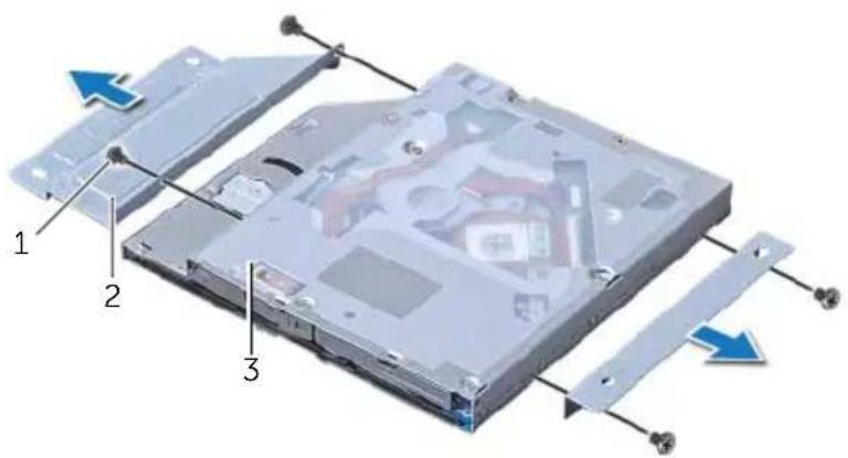
text_image
Diagram of an open DVD drive showing labeled components and directional arrows indicating assembly or movement.1 screws (4) 2 optical-drive brackets (2)
3 optical drive

WARNING: Before working inside your computer, read the safety information that shipped with your computer and follow the steps in "Before You Begin" on page 11. After working inside your computer, follow the instructions in "After Working Inside Your Computer" on page 13. For additional safety best practices information, see the Regulatory Compliance Homepage at dell.com/regulatory_compliance.
Procedure
1 Align the screw holes on the optical-drive brackets with the screw holes on the optical drive and replace the screws that secure the optical-drive brackets to the optical drive.
2 Connect the power and data-cable connector to the optical-drive assembly.
3 Align the screw holes on the optical-drive assembly with the screw holes on the computer base.
4 Replace the screws that secure the optical-drive assembly to the computer base.
Postrequisites
1 Replace the back cover. See "Replacing the Back Cover" on page 21.
10
Removing the System-Board Shield

WARNING: Before working inside your computer, read the safety information that shipped with your computer and follow the steps in "Before You Begin" on page 11. After working inside your computer, follow the instructions in "After Working Inside Your Computer" on page 13. For additional safety best practices information, see the Regulatory Compliance Homepage at dell.com/regulatory_compliance.
Prerequisites
1 Remove the back cover. See "Removing the Back Cover" on page 19.
Procedure
1 Remove the screws that secure the system-board shield to the computer base.
2 Lift the system-board shield off the computer base.
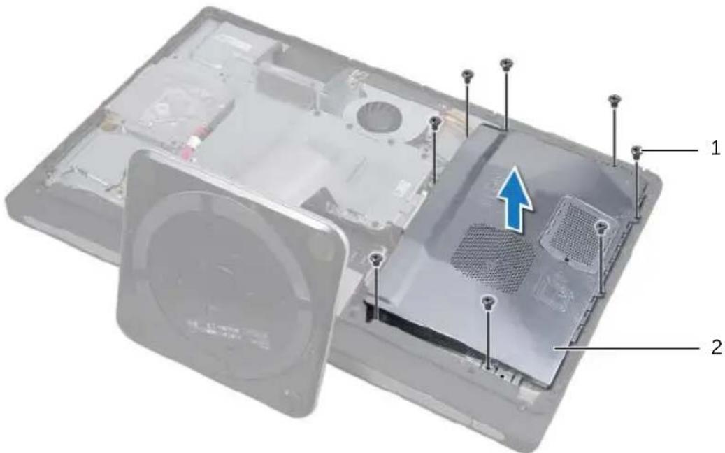
text_image
Labeled diagram of a computer fan base showing internal components and a blue arrow indicating a specific area.1 screws (8) 2 system-board shield
11
Replacing the System-Board Shield

WARNING: Before working inside your computer, read the safety information that shipped with your computer and follow the steps in "Before You Begin" on page 11. After working inside your computer, follow the instructions in "After Working Inside Your Computer" on page 13. For additional safety best practices information, see the Regulatory Compliance Homepage at dell.com/regulatory_compliance.
Procedure
1 Align the screw holes on the system-board shield with the screw holes on the computer base.
2 Replace the screws that secure the system-board shield to the computer base.
Postrequisites
1 Replace the back cover. See "Replacing the Back Cover" on page 21.
12
Removing the Power-Supply Unit

WARNING: Before working inside your computer, read the safety information that shipped with your computer and follow the steps in "Before You Begin" on page 11. After working inside your computer, follow the instructions in "After Working Inside Your Computer" on page 13. For additional safety best practices information, see the Regulatory Compliance Homepage at dell.com/regulatory_compliance.
Prerequisites
1 Remove the back cover. See "Removing the Back Cover" on page 19.
2 Remove the stand. See "Removing the Stand" on page 47.
3 Remove the system-board shield. See "Removing the System-Board Shield" on page 31.
4 Remove the trim cover. See "Removing the Trim Cover" on page 87.
5 Remove the I/O panel. See "Removing the I/O Panel" on page 91.
Procedure
1 Press the securing clips and disconnect the main and processor power-supply cables from the system board.
2 Remove the main and processor power-supply cables from their routing guides.
3 Press the securing clip on the power-port cable connector and disconnect the power-port cable from the power-supply unit.
4 Disconnect the power-supply indicator cable from the power-supply unit.
5 Lift the securing clip and disconnect the power-supply fan cable from the power-supply unit.
6 Remove the screws that secure the power-supply unit to the computer base.
7 Lift the power-supply unit off the computer base.
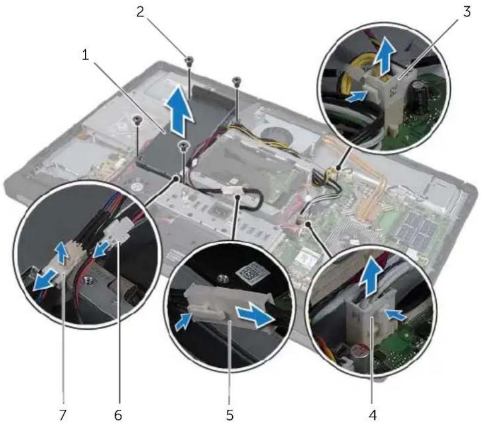
text_image
Labeled diagram of a computer motherboard showing numbered components and directional arrows indicating movement or assembly.1 power-supply unit 2 screws (4)
3 processor power-supply cable connector 4 main power-supply cable connector
5 power-port cable 6 power-supply indicator cable connector
7 power-supply fan cable connector
13
Replacing the Power-Supply Unit

WARNING: Before working inside your computer, read the safety information that shipped with your computer and follow the steps in "Before You Begin" on page 11. After working inside your computer, follow the instructions in "After Working Inside Your Computer" on page 13. For additional safety best practices information, see the Regulatory Compliance Homepage at dell.com/regulatory_compliance.
Procedure
1 Align the screw holes on the power-supply unit with the screw holes on the computer base and replace the screws that secure the power-supply unit to the computer base.
2 Connect the power-supply fan cable to the power-supply unit.
3 Connect the power-supply indicator cable to the power-supply unit.
4 Connect the power-port cable to the power-supply unit.
5 Route the processor and main power-supply cables through their routing guides.
6 Connect the processor and main power-supply cables to the system board.
Postrequisites
1 Replace the I/O panel. See "Replacing the I/O Panel" on page 93.
2 Replace the trim cover. See "Replacing the Trim Cover" on page 89.
3 Replace the system-board shield. See "Replacing the System-Board Shield" on page 33.
4 Replace the stand. See "Replacing the Stand" on page 49.
5 Replace the back cover. See "Replacing the Back Cover" on page 21.
14
Removing the Memory Module(s)

WARNING: Before working inside your computer, read the safety information that shipped with your computer and follow the steps in "Before You Begin" on page 11. After working inside your computer, follow the instructions in "After Working Inside Your Computer" on page 13. For additional safety best practices information, see the Regulatory Compliance Homepage at dell.com/regulatory_compliance.
Prerequisites
1 Remove the Back Cover. See "Removing the Back Cover" on page 19.
Procedure
1 Remove the screw that secures the memory-module shield to the system-board shield.
2 Slide the memory-module shield toward the bottom of the computer to remove it from the system-board shield.
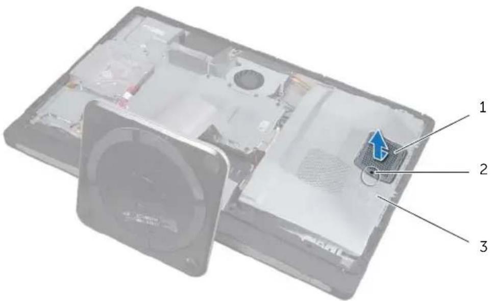
text_image
Diagram of a device interior with labeled parts, showing open and closed views of a fan or fan assembly.1 memory-module shield 2 screw
3 system - board shield
3 Use your fingertips to carefully spread apart the securing clips on each end of the memory-module connector until the memory module pops up.
4 Remove the memory module from the memory-module connector.
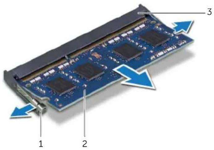
text_image
Diagram of a computer RAM module with labeled components and directional arrows indicating assembly or movement.1 securing-clips (2) 2 memory module
3 memory-module connector
15
Replacing the Memory Module(s)

WARNING: Before working inside your computer, read the safety information that shipped with your computer and follow the steps in "Before You Begin" on page 11. After working inside your computer, follow the instructions in "After Working Inside Your Computer" on page 13. For additional safety best practices information, see the Regulatory Compliance Homepage at dell.com/regulatory_compliance.
Procedure
1 Align the notch on the memory module with the tab on the memory-module connector.
2 Slide the memory module firmly into the connector at a 45-degree angle and press the memory module down until it clicks into place. If you do not hear the click, remove the memory module and reinstall it.
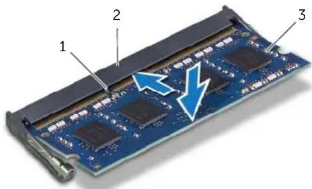
text_image
1 2 31 tab 2 memory-module connector
| 3 | m | e | m | o | r | y | m | o | d | u | l | e |
3 Slide the memory-module shield on the system-board shield and replace the screw that secures the memory-module shield to the system-board shield.
Postrequisites
1 Replace the back cover. See "Replacing the Back Cover" on page 21.
16
Removing the Coin-Cell Battery

WARNING: Before working inside your computer, read the safety information that shipped with your computer and follow the steps in "Before You Begin" on page 11. After working inside your computer, follow the instructions in "After Working Inside Your Computer" on page 13. For additional safety best practices information, see the Regulatory Compliance Homepage at dell.com/regulatory_compliance.

WARNING: The battery may explode if installed incorrectly. Replace the battery only with the same or equivalent type. Discard used batteries according to the manufacturer's instructions.

CAUTION: Removing the coin-cell battery resets the BIOS settings to default. It is recommended that you note the BIOS settings before removing the coin-cell battery.
Prerequisites
1 Remove the back cover. See "Removing the Back Cover" on page 19.
2 Remove the system-board shield. See "Removing the System-Board Shield" on page 31.
Procedure
1 Press the securing clip away from the coin-cell battery till the coin-cell battery pops out.
2 Lift the coin-cell battery out of its socket.
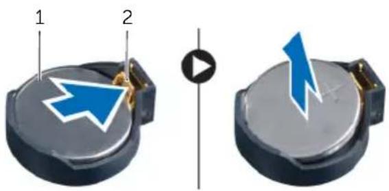
text_image
1 21 coin-cell battery 2 securing clip
17
Replacing the Coin-Cell Battery

WARNING: Before working inside your computer, read the safety information that shipped with your computer and follow the steps in "Before You Begin" on page 11. After working inside your computer, follow the instructions in "After Working Inside Your Computer" on page 13. For additional safety best practices information, see the Regulatory Compliance Homepage at dell.com/regulatory_compliance.

WARNING: The battery may explode if installed incorrectly. Replace the battery only with the same or equivalent type. Discard used batteries according to the manufacturer's instructions.
Procedure
1 With the positive-side facing up, snap the coin-cell battery into the coin-cell battery socket on the system board.
Postrequisites
1 Replace the system-board shield. See "Replacing the System-Board Shield" on page 33.
2 Replace the back cover. See "Replacing the Back Cover" on page 21.
18
Removing the Stand

WARNING: Before working inside your computer, read the safety information that shipped with your computer and follow the steps in "Before You Begin" on page 11. After working inside your computer, follow the instructions in "After Working Inside Your Computer" on page 13. For additional safety best practices information, see the Regulatory Compliance Homepage at dell.com/regulatory_compliance.
Prerequisites
1 Remove the Back Cover. See "Removing the Back Cover" on page 19.
Procedure
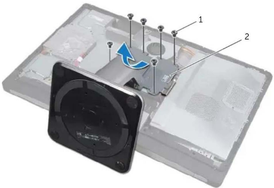
1 Remove the screws that secure the stand to the hard-drive cage.
2 Lift the stand off the computer base.
text_image
Labeled diagram of a device showing internal components with numbered parts and an arrow indicating rotation or movement.1 screws (6) 2 stand
19
Replacing the Stand

WARNING: Before working inside your computer, read the safety information that shipped with your computer and follow the steps in "Before You Begin" on page 11. After working inside your computer, follow the instructions in "After Working Inside Your Computer" on page 13. For additional safety best practices information, see the Regulatory Compliance Homepage at dell.com/regulatory_compliance.
Procedure
1 Insert the tab at the top of the stand into the slot on the computer base.
2 Align the screw holes on the stand with the screw holes on the hard-drive cage.
3 Replace the screws that secure the stand to the hard-drive cage.
Postrequisites
1 Replace the back cover. See "Replacing the Back Cover" on page 21.
20
Removing the Hard Drive

WARNING: Before working inside your computer, read the safety information that shipped with your computer and follow the steps in "Before You Begin" on page 11. After working inside your computer, follow the instructions in "After Working Inside Your Computer" on page 13. For additional safety best practices information, see the Regulatory Compliance Homepage at dell.com/regulatory_compliance.

CAUTION: To avoid data loss, do not remove the hard drive while the computer is in Sleep or On state.

CAUTION: Hard drives are extremely fragile. Exercise care when handling the hard drive.
Prerequisites
1 Remove the back cover. See "Removing the Back Cover" on page 19.
2 Remove the stand. See "Removing the Stand" on page 47.
Procedure
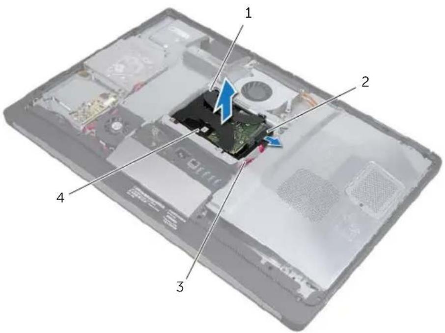
1 Using the straps on the hard-drive assembly, gently lift the hard-drive assembly out of the hard-drive cage.
2 Disconnect the power and data-cable connector from the hard-drive assembly.
text_image
Labeled diagram of a device showing internal components with numbered parts and highlighted areas1 straps (2) 2 power and data-cable connector
3 power and data cables 4 hard-drive assembly
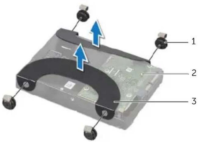
3 Remove the screws that secure the straps to the hard drive and remove the straps from the hard drive.
text_image
Diagram of a device rear panel with labeled parts and directional arrows indicating movement or assembly.1 screws (4) 2 hard drive
3 s t r a p s ( 2 )
21
Replacing the Hard Drive

WARNING: Before working inside your computer, read the safety information that shipped with your computer and follow the steps in "Before You Begin" on page 11. After working inside your computer, follow the instructions in "After Working Inside Your Computer" on page 13. For additional safety best practices information, see the Regulatory Compliance Homepage at dell.com/regulatory_compliance.

CAUTION: Hard drives are extremely fragile. Exercise care when handling the hard drive.
Procedure
1 Align the screw holes on the straps with the screw holes on the hard drive and replace the screws that secure the straps to the hard drive.
2 Connect the power and data-cable connector to the hard-drive assembly.
3 With the straps facing up, align the hard-drive assembly screws with the slots on the hard-drive cage, and then gently press down the hard-drive assembly.
Postrequisites
1 Replace the stand. See "Replacing the Stand" on page 49.
2 Replace the back cover. See "Replacing the Back Cover" on page 21.
22
Removing the Hard-Drive Cage

WARNING: Before working inside your computer, read the safety information that shipped with your computer and follow the steps in "Before You Begin" on page 11. After working inside your computer, follow the instructions in "After Working Inside Your Computer" on page 13. For additional safety best practices information, see the Regulatory Compliance Homepage at dell.com/regulatory_compliance.
Prerequisites
1 Remove the back cover. See "Removing the Back Cover" on page 19.
2 Remove the stand. See "Removing the Stand" on page 47.
3 Follow step 1 to step 2 in "Removing the Hard Drive" on page 51.
Procedure
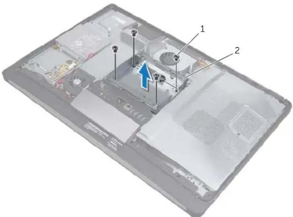
1 Remove the screws that secure the hard-drive cage to the computer base.
2 Remove the power cables from the routing guides on the hard-drive cage.
3 Lift the hard-drive cage off the computer base.
text_image
Labeled diagram of a device interior showing internal components with numbered parts and a blue arrow indicating a specific area.1 screws (4) 2 hard-drive cage

WARNING: Before working inside your computer, read the safety information that shipped with your computer and follow the steps in "Before You Begin" on page 11. After working inside your computer, follow the instructions in "After Working Inside Your Computer" on page 13. For additional safety best practices information, see the Regulatory Compliance Homepage at dell.com/regulatory_compliance.
Procedure
1 Align the screw holes on the hard-drive cage with the screw holes on the computer base.
2 Replace the screws that secure the hard-drive cage to the computer base.
Postrequisites
1 Follow step 2 to step 3 in "Replacing the Hard Drive" on page 53.
2 Replace the stand. See "Replacing the Stand" on page 49.
3 Replace the back cover. See "Replacing the Back Cover" on page 21.
24
Removing the Power-Supply Fan

WARNING: Before working inside your computer, read the safety information that shipped with your computer and follow the steps in "Before You Begin" on page 11. After working inside your computer, follow the instructions in "After Working Inside Your Computer" on page 13. For additional safety best practices information, see the Regulatory Compliance Homepage at dell.com/regulatory_compliance.
Prerequisites
1 Remove the back cover. See "Removing the Back Cover" on page 19.
Procedure
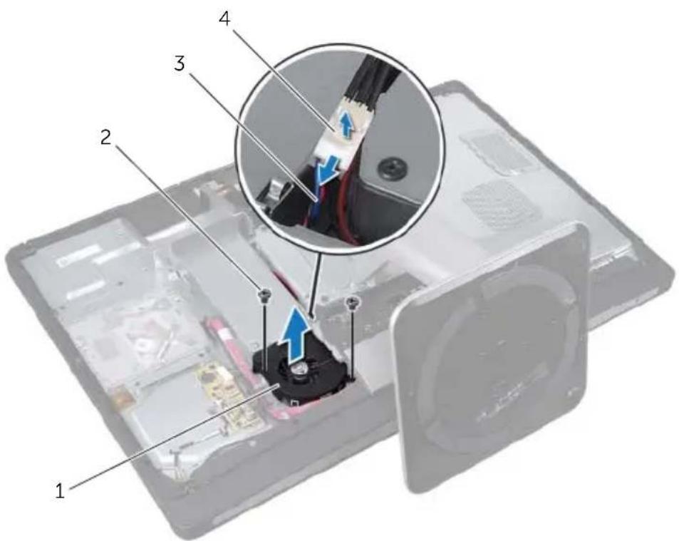
1 Lift the securing tab and disconnect the power-supply fan cable from the power-supply unit.
2 Remove the screws that secure the power-supply fan to the computer base.
3 Gently lift the power-supply fan and ease the power-supply fan cable from under the I/O-board assembly.
4 Lift the power-supply fan off the computer base.
text_image
Labeled diagram of a computer monitor showing internal components and cable assembly with numbered parts1 power-supply fan 2 screws (2)
3 power-supply fan cable 4 securing tab
25
Replacing the Power-Supply Fan

WARNING: Before working inside your computer, read the safety information that shipped with your computer and follow the steps in "Before You Begin" on page 11. After working inside your computer, follow the instructions in "After Working Inside Your Computer" on page 13. For additional safety best practices information, see the Regulatory Compliance Homepage at dell.com/regulatory_compliance.
Procedure
1 Route the power-supply fan cable under the I/O-board assembly and then connect the power-supply fan cable to the power-supply unit.
2 Align the screw holes on the power-supply fan with the screw holes on the computer base and replace the screws that secure the power-supply fan to the computer base.
Postrequisites
1 Replace the back cover. See "Replacing the Back Cover" on page 21.
26
Removing the TV-Tuner Mini-Card

WARNING: Before working inside your computer, read the safety information that shipped with your computer and follow the steps in "Before You Begin" on page 11. After working inside your computer, follow the instructions in "After Working Inside Your Computer" on page 13. For additional safety best practices information, see the Regulatory Compliance Homepage at dell.com/regulatory_compliance.
Prerequisites
1 Remove the back cover. See "Removing the Back Cover" on page 19.
2 Remove the system-board shield. See "Removing the System-Board Shield" on page 31.
Procedure
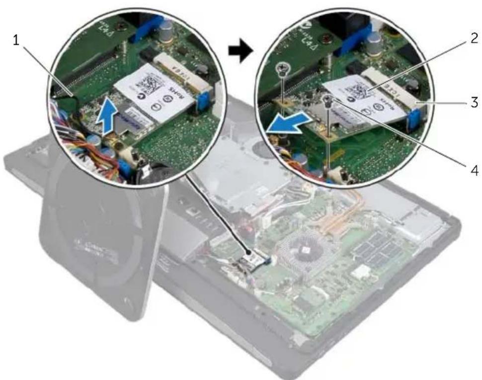
1 Disconnect the TV-in port cable from the TV-tuner mini-card.
2 Remove the screws that secure the TV-tuner mini-card to the system board.
3 Slide and remove the TV-tuner card out of the TV-tuner mini-card connector.
text_image
Laptop screen with close-up views of a circuit board and a CPU, showing labeled components 1 to 41 TV-in port cable 2 TV-tuner mini-card
3 TV-tuner mini-card connector 4 screws (2)

WARNING: Before working inside your computer, read the safety information that shipped with your computer and follow the steps in "Before You Begin" on page 11. After working inside your computer, follow the instructions in "After Working Inside Your Computer" on page 13. For additional safety best practices information, see the Regulatory Compliance Homepage at dell.com/regulatory_compliance.
Procedure
1 Align the notch on the TV-tuner mini-card with the tab on the TV-tuner mini-card connector.
2 Insert the TV -tuner mini-card at a 45-degree angle into the TV-tuner mini-card connector.
3 Press the outer end of the TV-tuner mini-card down and replace the screws that secure the TV-tuner mini-card to the system board.
4 Connect the TV-in port cable to the TV-tuner mini-card.
Postrequisites
1 Replace the system-board shield. See "Replacing the System-Board Shield" on page 33.
2 Replace the back cover. See "Replacing the Back Cover" on page 21.
28
Removing the Wireless Mini-Card

WARNING: Before working inside your computer, read the safety information that shipped with your computer and follow the steps in "Before You Begin" on page 11. After working inside your computer, follow the instructions in "After Working Inside Your Computer" on page 13. For additional safety best practices information, see the Regulatory Compliance Homepage at dell.com/regulatory_compliance.
Prerequisites
1 Remove the back cover. See "Removing the Back Cover" on page 19.
2 Remove the system-board shield. See "Removing the System-Board Shield" on page 31.
Procedure
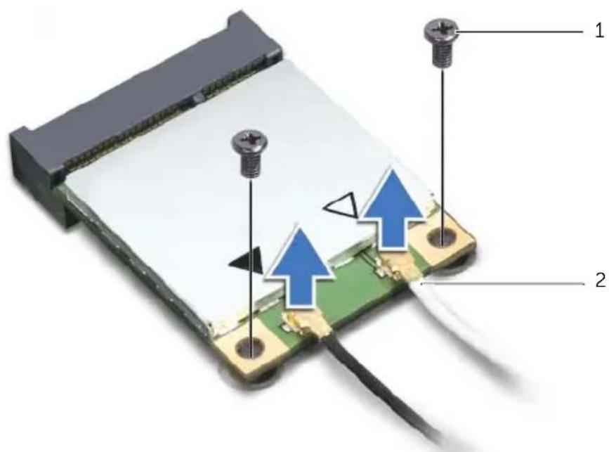
1 Disconnect the antenna cables from the wireless mini-card.
2 Remove the screws that secure the wireless mini-card to the system board.
text_image
Diagram of a device with labeled components and arrows indicating assembly or installation steps1 screws (2) 2 antenna cables (2)
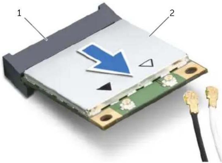
3 Slide and remove the wireless mini-card out of the wireless mini-card connector.
text_image
Diagram of an electronic component with labeled parts and a blue arrow indicating a downward trend or direction.1 wireless mini-card connector 2 wireless mini-card

WARNING: Before working inside your computer, read the safety information that shipped with your computer and follow the steps in "Before You Begin" on page 11. After working inside your computer, follow the instructions in "After Working Inside Your Computer" on page 13. For additional safety best practices information, see the Regulatory Compliance Homepage at dell.com/regulatory_compliance.
Procedure

CAUTION: To avoid damage to the mini-card, ensure that no cables are placed under the wireless mini-card.
1 Align the notch on the wireless mini-card with the tab on the wireless mini-card connector.
2 Insert the wireless mini-card at a 45-degree angle into the wireless mini-card connector.
3 Press the outer end of the wireless mini-card down and replace the screws that secure the wireless mini-card to the system board.
4 Connect the antenna cables to the wireless mini-card.
The following table provides the wireless-antenna cable color schemes for the wireless mini-cards supported by your computer.
Connectors on the mini-card Wireless-antenna cable color schemes
| WLAN + Bluetooth (2 cables) | |
| Main WLAN + Bluetooth (white triangle) | white |
| Auxiliary WLAN + Bluetooth (black triangle) | black |
Postrequisites
1 Replace the system-board shield. See "Replacing the System-Board Shield" on page 33.
2 Replace the back cover. See "Replacing the Back Cover" on page 21.
30
Removing the mSATA Mini-Card

WARNING: Before working inside your computer, read the safety information that shipped with your computer and follow the steps in "Before You Begin" on page 11. After working inside your computer, follow the instructions in "After Working Inside Your Computer" on page 13. For additional safety best practices information, see the Regulatory Compliance Homepage at dell.com/regulatory_compliance.
Prerequisites
1 Remove the back cover. See "Removing the Back Cover" on page 19.
2 Remove the system-board shield. See "Removing the System-Board Shield" on page 31.
Procedure
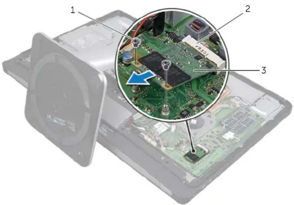
1 Remove the screws that secure the mSATA mini-card to the system board.
2 Slide and remove the mSATA mini-card from the mSATA mini-card connector.
text_image
Labeled diagram of an electronic circuit board showing components 1, 2, and 3 with a magnified inset highlighting a chip structure.1 screws (2) 2 mSATA mini-card connector
3 m S A T A m i n i - c a r d
31
Replacing the mSATA Mini-Card

WARNING: Before working inside your computer, read the safety information that shipped with your computer and follow the steps in "Before You Begin" on page 11. After working inside your computer, follow the instructions in "After Working Inside Your Computer" on page 13. For additional safety best practices information, see the Regulatory Compliance Homepage at dell.com/regulatory_compliance.
Procedure
1 Align the notch on the mSATA mini-card with the tab on the mSATA mini-card connector.
2 Insert the mSATA mini-card at a 45-degree angle into the mSATA mini-card connector.
3 Replace the screws that secure the mSATA mini-card to the system board.
Postrequisites
1 Replace the system-board shield. See "Replacing the System-Board Shield" on page 33.
2 Replace the back cover. See "Replacing the Back Cover" on page 21.
32
Removing the Processor Heat-Sink Fan

WARNING: Before working inside your computer, read the safety information that shipped with your computer and follow the steps in "Before You Begin" on page 11. After working inside your computer, follow the instructions in "After Working Inside Your Computer" on page 13. For additional safety best practices information, see the Regulatory Compliance Homepage at dell.com/regulatory_compliance.
Prerequisites
1 Remove the back cover. See "Removing the Back Cover" on page 19.
2 Remove the system-board shield. See "Removing the System-Board Shield" on page 31.
Procedure
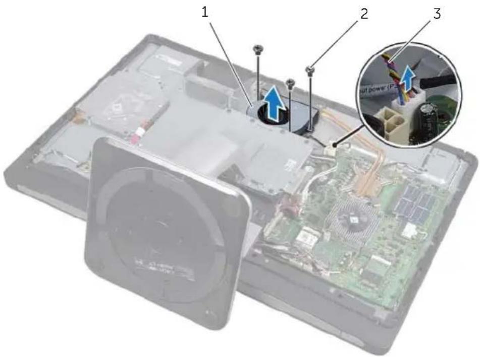
1 Disconnect the processor heat-sink fan cable from the system board.
2 Remove the screws that secure the processor heat-sink fan to the computer base.
3 Lift the processor heat-sink fan off the computer base.
text_image
Exploded view diagram of a computer with labeled components and a magnified inset showing power repair details.1 processor heat-sink fan 2 screw (3)
3 processor heat-sink fan cable

WARNING: Before working inside your computer, read the safety information that shipped with your computer and follow the steps in "Before You Begin" on page 11. After working inside your computer, follow the instructions in "After Working Inside Your Computer" on page 13. For additional safety best practices information, see the Regulatory Compliance Homepage at dell.com/regulatory_compliance.
Procedure
1 Align the screw holes on the processor heat-sink fan with the screw holes on the computer base and replace the screws that secure the processor heat-sink fan to the computer base.
2 Connect the processor heat-sink fan cable to the system board.
Postrequisites
1 Replace the system-board shield. See "Replacing the System-Board Shield" on page 33.
2 Replace the back cover. See "Replacing the Back Cover" on page 21.
34 Removing the Processor Heat-Sink

WARNING: Before working inside your computer, read the safety information that shipped with your computer and follow the steps in "Before You Begin" on page 11. After working inside your computer, follow the instructions in "After Working Inside Your Computer" on page 13. For additional safety best practices information, see the Regulatory Compliance Homepage at dell.com/regulatory_compliance.
Prerequisites
1 Remove the back cover. See "Removing the Back Cover" on page 19.
2 Remove the system-board shield. See "Removing the System-Board Shield" on page 31.
Procedure
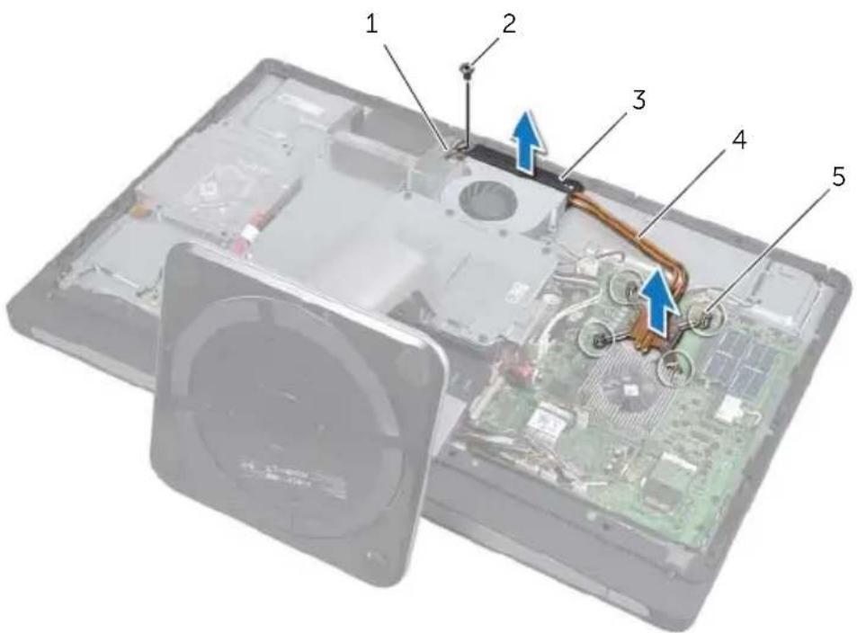
1 Remove the screw that secures the cooling vents and the grounding cable to the computer base.
2 In sequential order (indicated on the processor heat-sink), loosen the captive screws that secure the processor heat-sink to the system board.
3 Lift the processor heat-sink off the system board.
text_image
Labeled diagram of an electronic device showing internal components and wiring, with numbered parts 1 to 5.1 grounding cable 2 screw
3 cooling vents 4 processor heat-sink
5 captive screws (4)

WARNING: Before working inside your computer, read the safety information that shipped with your computer and follow the steps in "Before You Begin" on page 11. After working inside your computer, follow the instructions in "After Working Inside Your Computer" on page 13. For additional safety best practices information, see the Regulatory Compliance Homepage at dell.com/regulatory_compliance.
Procedure

NOTE: The original thermal grease can be reused if the original system board and heat sink are reinstalled together. If either the system board or the heat sink is replaced with a new one, use the thermal pad provided in the kit to ensure that thermal conductivity is achieved.
1 Clean the thermal grease from the bottom of the processor heat-sink and reapply the thermal grease.
2 Align the captive screws on the processor heat-sink with the screw holes on the system board.
3 In sequential order (indicated on the processor heat-sink), tighten the captive screws that secure the processor heat-sink to the system board.
4 Replace the screw that secures the cooling vents and the grounding cable to the computer base.
Postrequisites
1 Replace the system-board shield. See "Replacing the System-Board Shield" on page 33.
2 Replace the back cover. See "Replacing the Back Cover" on page 21.
36
Removing the Processor

WARNING: Before working inside your computer, read the safety information that shipped with your computer and follow the steps in "Before You Begin" on page 11. After working inside your computer, follow the instructions in "After Working Inside Your Computer" on page 13. For additional safety best practices information, see the Regulatory Compliance Homepage at dell.com/regulatory_compliance.

CAUTION: Processors are extremely fragile. Handle the processor only by the edges and do not touch the metal pins.
Prerequisites
1 Remove the back cover. See "Removing the Back Cover" on page 19.
2 Remove the system-board shield. See "Removing the System-Board Shield" on page 31.
3 Remove the processor heat-sink. See "Removing the Processor Heat-Sink" on page 79
Procedure
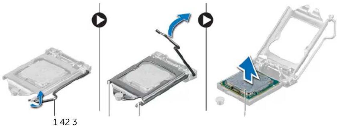
1 Press the release-lever down and then pull it outwards to release it from the securing tab.
2 Extend the release-lever completely to open the processor cover.
3 Gently lift the processor and remove it from the processor socket.
text_image
1 42 31 release lever 2 processor cover
3 securing tab 4 processor

WARNING: Before working inside your computer, read the safety information that shipped with your computer and follow the steps in "Before You Begin" on page 11. After working inside your computer, follow the instructions in "After Working Inside Your Computer" on page 13. For additional safety best practices information, see the Regulatory Compliance Homepage at dell.com/regulatory_compliance.
Procedure
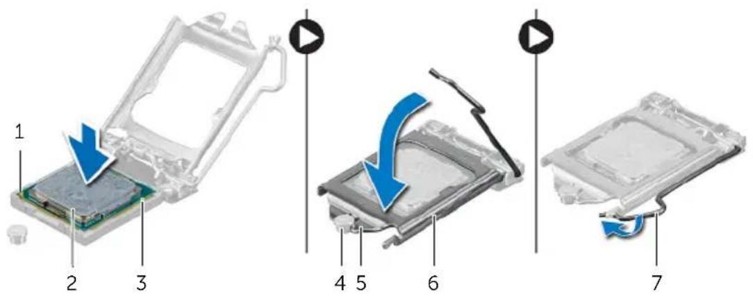
1 Ensure that the release lever on the processor socket is fully extended in the open position.

CAUTION: You must position the processor correctly in the processor socket to avoid permanent damage to the processor.
2 Align the notches on the processor with the tabs on the processor socket.
3 Align the pin-1 corner on the processor with the pin-1 corner on the processor socket, and then place the processor in the processor socket.

CAUTION: Ensure that the processor-cover notch is positioned underneath the alignment post.
4 When the processor is fully seated in the socket, close the processor cover.
5 Pivot the release-lever down and place it under the tab on the processor cover.
text_image
1 2 3 4 5 6 71 processor pin-1 indicator 2 processor
3 alignment tabs (2) 4 alignment post
5 processor-cover notch 6 processor cover
1 Replace the processor heat-sink. See "Replacing the Processor Heat-Sink" on page 81.
2 Replace the system-board shield. See "Replacing the System-Board Shield" on page 33.
3 Replace the back cover. See "Replacing the Back Cover" on page 21.

WARNING: Before working inside your computer, read the safety information that shipped with your computer and follow the steps in "Before You Begin" on page 11. After working inside your computer, follow the instructions in "After Working Inside Your Computer" on page 13. For additional safety best practices information, see the Regulatory Compliance Homepage at dell.com/regulatory_compliance.
Prerequisites
1 Remove the back cover. See "Removing the Back Cover" on page 19.
Procedure
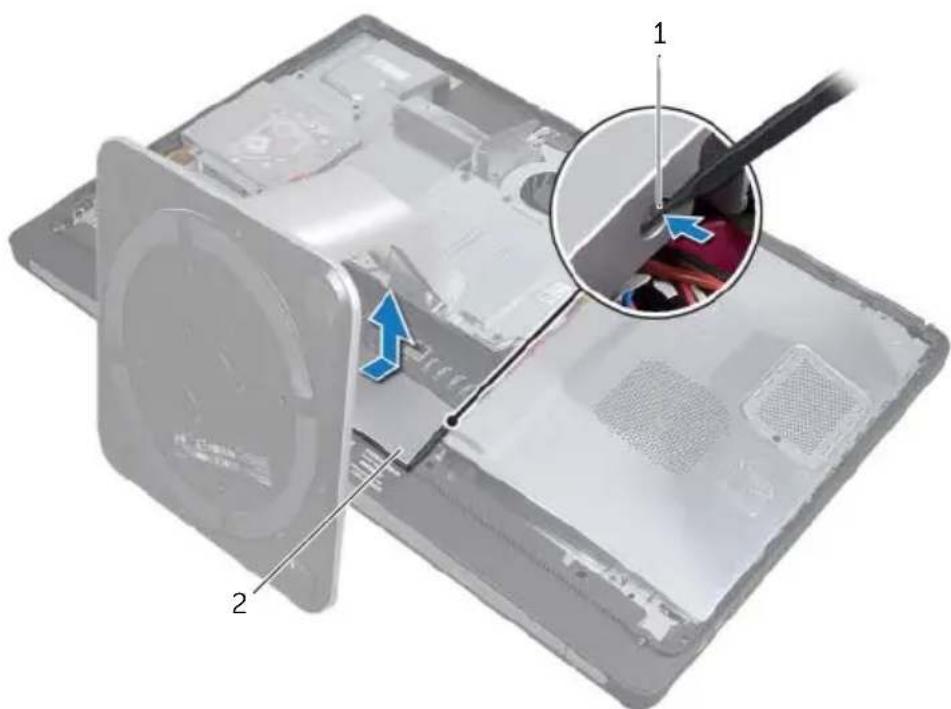
1 Using a plastic scribe, press-in on the tabs to release the trim cover from the inner frame.
2 Slide the trim cover toward the top of the computer and then lift the trim cover off the computer base.
text_image
Technical diagram of a device showing internal components with labeled parts 1 and 2, including a magnified inset highlighting a component.1 tabs (2) 2 trim cover

WARNING: Before working inside your computer, read the safety information that shipped with your computer and follow the steps in "Before You Begin" on page 11. After working inside your computer, follow the instructions in "After Working Inside Your Computer" on page 13. For additional safety best practices information, see the Regulatory Compliance Homepage at dell.com/regulatory_compliance.
Procedure
1 Insert the tabs at the bottom of the trim cover into the slots on the inner frame.
2 Press down on the trim cover until the tabs on the inner frame are secured in the slots on either side of the trim cover.
Postrequisites
1 Replace the back cover. See "Replacing the Back Cover" on page 21.

WARNING: Before working inside your computer, read the safety information that shipped with your computer and follow the steps in "Before You Begin" on page 11. After working inside your computer, follow the instructions in "After Working Inside Your Computer" on page 13. For additional safety best practices information, see the Regulatory Compliance Homepage at dell.com/regulatory_compliance.
Prerequisites
1 Remove the back cover. See "Removing the Back Cover" on page 19.
2 Remove the stand. See "Removing the Stand" on page 47.
3 Remove the trim cover. See "Removing the Trim Cover" on page 87.
Procedure
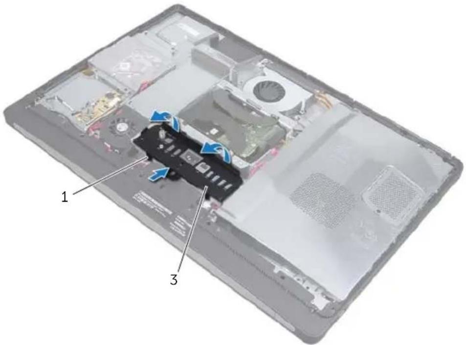
1 Press the I/O panel towards the top of the computer and then pivot the I/O panel upward.
2 Ease the securing tabs on the I/O panel and lift the I/O panel off the computer base.
text_image
Labeled diagram of a laptop showing internal components with numbered parts and blue arrows indicating features1 securing tabs 2 I/O panel
41
Replacing the I/O Panel

WARNING: Before working inside your computer, read the safety information that shipped with your computer and follow the steps in "Before You Begin" on page 11. After working inside your computer, follow the instructions in "After Working Inside Your Computer" on page 13. For additional safety best practices information, see the Regulatory Compliance Homepage at dell.com/regulatory_compliance.
Procedure
1 Align the slots on the I/O panel with the ports on the I/O assembly.
2 Press down on the I/O panel till it snaps into place.
Postrequisites
1 Replace the trim cover. See "Replacing the Trim Cover" on page 89.
2 Replace the stand. See "Replacing the Stand" on page 49.
3 Replace the back cover. See "Replacing the Back Cover" on page 21.
42
Removing the Inner Frame

WARNING: Before working inside your computer, read the safety information that shipped with your computer and follow the steps in "Before You Begin" on page 11. After working inside your computer, follow the instructions in "After Working Inside Your Computer" on page 13. For additional safety best practices information, see the Regulatory Compliance Homepage at dell.com/regulatory_compliance.
Prerequisites
1 Remove the back cover. See "Removing the Back Cover" on page 19.
2 Remove the stand. See "Removing the Stand" on page 47.
3 Remove the system-board shield. See "Removing the System-Board Shield" on page 31.
4 Remove the trim cover. See "Removing the Trim Cover" on page 87.
5 Remove the I/O panel. See "Removing the I/O Panel" on page 91.
Procedure
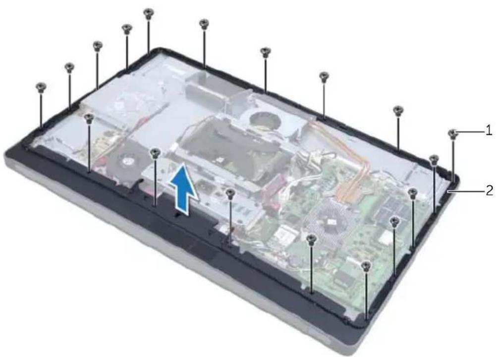
1 Remove the screws that secure the inner frame to the computer base.
2 Gently pry the inner frame from the sides and lift the inner frame off the computer base.
text_image
Labeled diagram of a device showing internal components with numbered parts and an arrow indicating a specific area.1 screws (18) 2 inner frame

WARNING: Before working inside your computer, read the safety information that shipped with your computer and follow the steps in "Before You Begin" on page 11. After working inside your computer, follow the instructions in "After Working Inside Your Computer" on page 13. For additional safety best practices information, see the Regulatory Compliance Homepage at dell.com/regulatory_compliance.
Procedure
1 Align the screw holes on the inner frame with the screw holes on the computer base.

NOTE: Ensure that all cables are routed through their routing guides and no cables are placed between the inner frame and the computer base.
2 Replace the screws that secure the inner frame to the computer base.
Postrequisites
1 Replace the I/O panel. See "Replacing the I/O Panel" on page 93.
2 Replace the trim cover. See "Replacing the Trim Cover" on page 89.
3 Replace the system-board shield. See "Replacing the System-Board Shield" on page 33.
4 Replace the stand. See "Replacing the Stand" on page 49.
5 Replace the back cover. "Replacing the Back Cover" on page 21.

WARNING: Before working inside your computer, read the safety information that shipped with your computer and follow the steps in "Before You Begin" on page 11. After working inside your computer, follow the instructions in "After Working Inside Your Computer" on page 13. For additional safety best practices information, see the Regulatory Compliance Homepage at dell.com/regulatory_compliance.
Prerequisites
1 Remove the back cover. See "Removing the Back Cover" on page 19.
2 Remove the stand. See "Removing the Stand" on page 47.
3 Remove the trim cover. See "Removing the Trim Cover" on page 87.
4 Remove the I/O panel. See "Removing the I/O Panel" on page 91.
5 Remove the system-board shield. See "Removing the System-Board Shield" on page 31.
6 Remove the inner frame. See "Removing the Inner Frame" on page 95.
Procedure
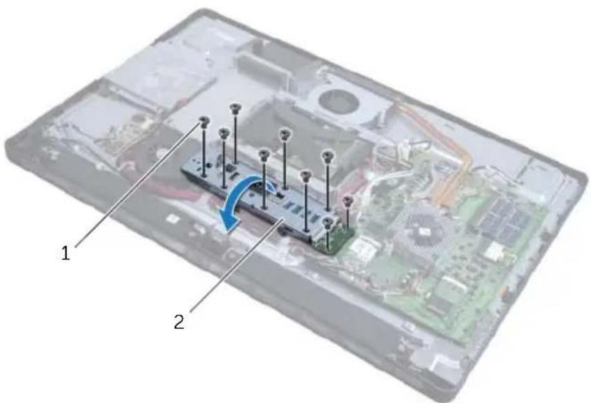
1 Remove the screws that secure the I/O-board assembly to the computer base.
2 Gently lift the I/O-board assembly from the computer base and turn the I/O-board assembly over.
text_image
Laptop interior diagram with labeled components and a blue arrow indicating a directional change or movement in the circuit board.1 screws (9) 2 I/O-board assembly
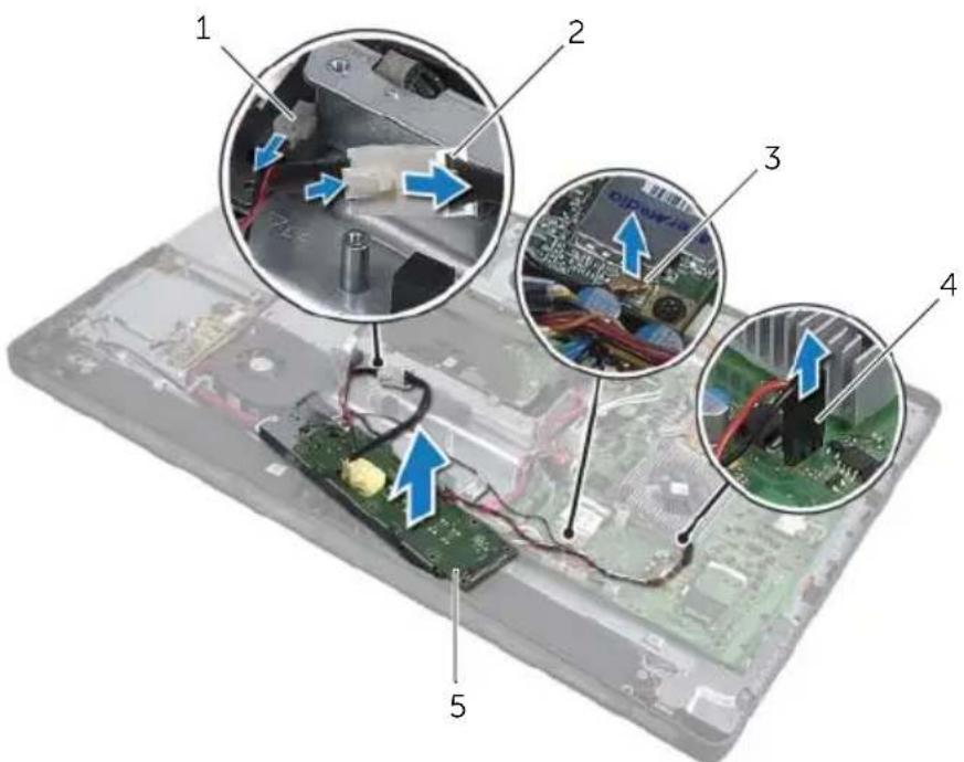
3 Press the securing clip and disconnect the power-port cable.
4 Note the routing of the TV-in port cable, infrared-emitter port cable, and the power-supply light cable, and then disconnect the cables from the system board.
5 Remove the TV-in port cable and the infrared-emitter port cable from their routing guides.
6 Lift the I/O-board assembly off the computer base.
text_image
Laptop interior with numbered components and close-up insets showing wiring and circuit boards1 power-supply light cable 2 power-port cable
3 TV-in port cable 4 infrared-emitter port cable
5 l / O - b o a r d a s s e m b l y
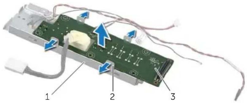
7 Push the securing tabs outward to release the I/O board and then lift the I/O board away from the I/O-board bracket.
text_image
Labeled diagram of an electronic device showing components 1, 2, and 3 with blue arrows indicating flow or movement.1 I/O-board bracket 2 securing tabs (4)
3 1 / O b o a r d

WARNING: Before working inside your computer, read the safety information that shipped with your computer and follow the steps in "Before You Begin" on page 11. After working inside your computer, follow the instructions in "After Working Inside Your Computer" on page 13. For additional safety best practices information, see the Regulatory Compliance Homepage at dell.com/regulatory_compliance.
Procedure
1 Slide the power-port cable and power-supply light cable through the slot on the I/O-board bracket.
2 Place the I/O board in the I/O-board bracket and press the securing tabs to secure the I/O board to the I/O-board bracket.
3 Route the TV-in port cable, infrared-emitter port cable, and the power-supply light cable through their routing guides and connect the cables to the system board.
4 Connect the power-port cable to the power-supply unit.
5 Align the screw holes on the I/O-board assembly with the screw holes on the computer base.
6 Press down on the I/O-board assembly to connect the I/O board to the system board.

NOTE: Ensure that no cables are placed under the I/O-board assembly.
7 Replace the screws that secure the I/O-board assembly to the computer base.
Postrequisites
1 Replace the inner frame. See "Replacing the Inner Frame" on page 97.
2 Replace the system-board shield. See "Replacing the System-Board Shield" on page 33.
3 Replace the I/O panel. See "Replacing the I/O Panel" on page 93.
4 Replace the trim cover. See "Replacing the Trim Cover" on page 89.
5 Replace the stand. See "Replacing the Stand" on page 49.
6 Replace the back cover. See "Replacing the Back Cover" on page 21.

WARNING: Before working inside your computer, read the safety information that shipped with your computer and follow the steps in "Before You Begin" on page 11. After working inside your computer, follow the instructions in "After Working Inside Your Computer" on page 13. For additional safety best practices information, see the Regulatory Compliance Homepage at dell.com/regulatory_compliance.
Prerequisites
1 Remove the back cover. See "Removing the Back Cover" on page 19.
2 Remove the stand. See "Removing the Stand" on page 47.
3 Remove the trim cover. See "Removing the Trim Cover" on page 87.
4 Remove the I/O panel. See "Removing the I/O Panel" on page 91.
5 Remove the system-board shield. See "Removing the System-Board Shield" on page 31.
6 Remove the inner frame. See "Removing the Inner Frame" on page 95.
7 Follow step 1 to step 6 in "Removing the I/O-Board" on page 99.
Procedure
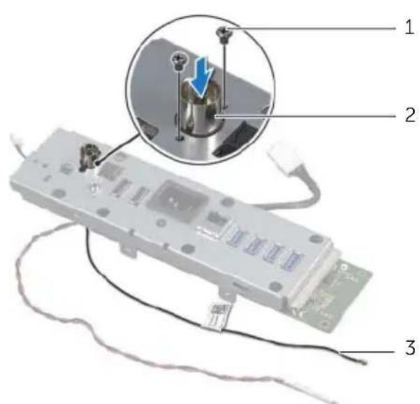
1 Remove the screws that secure the TV-in port to the I/O-board bracket.
2 Slide and remove the TV-in port through the slot on the I/O bracket.
text_image
Diagram showing a device with labeled parts and an inset close-up highlighting a mechanical component with a blue arrow.1 s c r e w s ( 2 ) 2 T V - i n p o r t
3 TV-in port cable

WARNING: Before working inside your computer, read the safety information that shipped with your computer and follow the steps in "Before You Begin" on page 11. After working inside your computer, follow the instructions in "After Working Inside Your Computer" on page 13. For additional safety best practices information, see the Regulatory Compliance Homepage at dell.com/regulatory_compliance.
Procedure
1 Slide the TV-in port cable through the slot on the I/O-board bracket.
2 Replace the screws that secure the TV-in port to the I/O-board bracket.
Postrequisites
1 Follow step 3 to step 7 in "Replacing the I/O Board" on page 101.
2 Replace the inner frame. See "Replacing the Inner Frame" on page 97.
3 Replace the system-board shield. See "Replacing the System-Board Shield" on page 33.
4 Replace the I/O panel. See "Replacing the I/O Panel" on page 93.
5 Replace the trim cover. See "Replacing the Trim Cover" on page 89.
6 Replace the stand. See "Replacing the Stand" on page 49.
7 Replace the back cover. See "Replacing the Back Cover" on page 21.

WARNING: Before working inside your computer, read the safety information that shipped with your computer and follow the steps in "Before You Begin" on page 11. After working inside your computer, follow the instructions in "After Working Inside Your Computer" on page 13. For additional safety best practices information, see the Regulatory Compliance Homepage at dell.com/regulatory_compliance.
Prerequisites
1 Remove the back cover. See "Removing the Back Cover" on page 19.
2 Remove the stand. See "Removing the Stand" on page 47.
3 Remove the trim cover. See "Removing the Trim Cover" on page 87.
4 Remove the I/O panel. See "Removing the I/O Panel" on page 91.
5 Remove the system-board shield. See "Removing the System-Board Shield" on page 31.
6 Remove the inner frame. See "Removing the Inner Frame" on page 95.
7 Follow step 1 to step 6 in "Removing the I/O-Board" on page 99.
Procedure
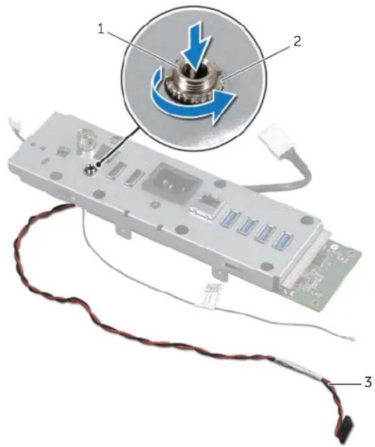
1 Remove the nut that secures the infrared-emitter port to the I/O-board bracket.
2 Remove the infrared-emitter port and the infrared-emitter port cable from the I/O-board assembly.
text_image
Diagram of an electronic device with labeled components and a magnified inset showing a mechanical component being inserted.1 Infrared-emitter port 2 nut
3 infrared-emitter port cable

WARNING: Before working inside your computer, read the safety information that shipped with your computer and follow the steps in "Before You Begin" on page 11. After working inside your computer, follow the instructions in "After Working Inside Your Computer" on page 13. For additional safety best practices information, see the Regulatory Compliance Homepage at dell.com/regulatory_compliance.
Procedure
1 Slide the infrared-emitter port through the slot on the I/O-board bracket.
2 Replace the nut that secures the infrared-emitter port to the I/O-board bracket.
Postrequisites
1 Follow step 3 to step 7 in "Replacing the I/O Board" on page 101.
2 Replace the inner frame. See "Replacing the Inner Frame" on page 97.
3 Replace the system-board shield. See "Replacing the System-Board Shield" on page 33.
4 Replace the I/O panel. See "Replacing the I/O Panel" on page 93.
5 Replace the trim cover. See "Replacing the Trim Cover" on page 89.
6 Replace the stand. See "Replacing the Stand" on page 49.
7 Replace the back cover. See "Replacing the Back Cover" on page 21.

WARNING: Before working inside your computer, read the safety information that shipped with your computer and follow the steps in "Before You Begin" on page 11. After working inside your computer, follow the instructions in "After Working Inside Your Computer" on page 13. For additional safety best practices information, see the Regulatory Compliance Homepage at dell.com/regulatory_compliance.

NOTE: Your computer's Service Tag is stored in the system board. You must enter the Service Tag in system setup after you replace the system board.

NOTE: Before disconnecting the cables from the system board, note the location of the connectors so that you can reconnect them correctly after you replace the system board.
Prerequisites
1 Remove the back cover. See "Removing the Back Cover" on page 19.
2 Remove the stand. See "Removing the Stand" on page 47.
3 Remove the trim cover. See "Removing the Trim Cover" on page 87.
4 Remove the I/O panel. See "Removing the I/O Panel" on page 91.
5 Remove the system-board shield. See "Removing the System-Board Shield" on page 31.
6 Remove the inner frame. See "Removing the Inner Frame" on page 95.
7 Follow step 1 to step 6 in "Removing the I/O-Board" on page 99.
8 Remove the memory modules. See "Removing the Memory Module(s)" on page 39.
9 Remove the TV-tuner mini-card. See "Removing the TV-Tuner Mini-Card" on page 63.
10 Remove the mSATA mini-card. See "Removing the mSATA Mini-Card" on page 71.
11 Remove the wireless mini-card. See "Removing the Wireless Mini-Card" on page 67.
12 Remove the processor heat-sink. See "Removing the Processor Heat-Sink" on page 79.
13 Remove the processor. See "Removing the Processor" on page 83.
Procedure
1 Disconnect the following cables from the system board:
- Speaker cable
- Power-button cable
- Converter cable
• Volume/Display-settings control cable - Hard-drive data cable
- Hard-drive power cable
• Optical-drive data cable
• Optical-drive power cable - Main and processor power-supply cables
- LVDS cable
- Touchscreen cable
- Processor heat-sink fan cable
- Display-power cable
- Camera cable
• Infrared-receiver cable

NOTE: For information on the location of the connectors, see "System-Board Components" on page 16.
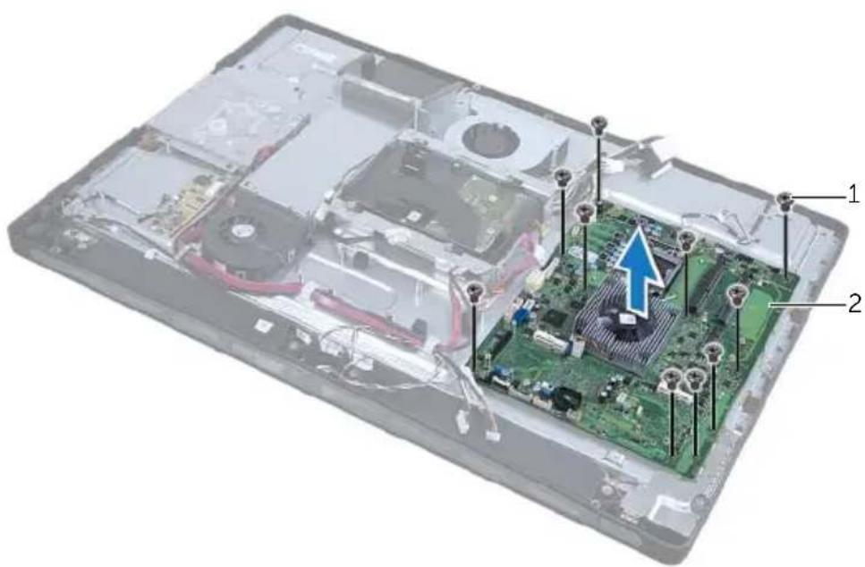
2 Remove the screws that secure the system board to the computer base.
3 Lift the system board off the computer base.
text_image
Labeled diagram of an electronic device showing internal components and a highlighted circuit board with arrows indicating assembly or connection.1 screws (10) 2 system board
51
Replacing the System Board

WARNING: Before working inside your computer, read the safety information that shipped with your computer and follow the steps in "Before You Begin" on page 11. After working inside your computer, follow the instructions in "After Working Inside Your Computer" on page 13. For additional safety best practices information, see the Regulatory Compliance Homepage at dell.com/regulatory_compliance.

NOTE: Your computer's Service Tag is stored in the system board. You must enter the Service Tag in the system setup after you replace the system board.
Procedure
1 Align the screw holes on the system board with the screw holes on the computer base.
2 Replace the screws that secure the system board to the computer base.
3 Connect the following cables to the system board:
- Speaker cable
- Power-button cable
- Converter cable
• Volume/Display-settings control cable - Hard-drive power cable
- Hard-drive data cable
• Optical-drive power cable
• Optical-drive data cable - Main and processor power-supply cables
- LVDS cable
- Touchscreen cable
- Processor heat-sink fan cable
- Display-power cable
- Camera cable
• Infrared-receiver cable
Postrequisites
1 Replace the processor. See "Replacing the Processor" on page 85.
2 Replace the processor heat-sink. See "Replacing the Processor Heat-Sink" on page 81.
3 Replace the wireless mini-card. See "Replacing the Wireless Mini-Card" on page 69.
4 Replace the mSATA mini-card. See "Replacing the mSATA Mini-Card" on page 73.
5 Replace the TV-tuner mini-card. See "Replacing the TV-Tuner Mini-Card" on page 65.
6 Replace the memory modules. See "Replacing the Memory Module(s)" on page 41.
7 Follow step 3 to step 7 in "Replacing the I/O Board" on page 101.
8 Replace the inner frame. See "Replacing the Inner Frame" on page 97.
9 Replace the system-board shield. See "Replacing the System-Board Shield" on page 33.
10 Replace the I/O panel. See "Replacing the I/O Panel" on page 93.
11 Replace the trim cover. See "Replacing the Trim Cover" on page 89.
12 Replace the stand. See "Replacing the Stand" on page 49.
13 Replace the back cover. See "Replacing the Back Cover" on page 21.
Entering the Service Tag in system setup
1 Turn on the computer.
2 Press
3 Navigate to the Main tab and enter the Service Tag in the Service Tag Input field.
52
Removing the Speakers

WARNING: Before working inside your computer, read the safety information that shipped with your computer and follow the steps in "Before You Begin" on page 11. After working inside your computer, follow the instructions in "After Working Inside Your Computer" on page 13. For additional safety best practices information, see the Regulatory Compliance Homepage at dell.com/regulatory_compliance.
Prerequisites
1 Remove the back cover. See "Removing the Back Cover" on page 19.
2 Remove the system-board shield. See "Removing the System-Board Shield" on page 31.
3 Remove the trim cover. See "Removing the Trim Cover" on page 87.
4 Remove the inner frame. See "Removing the Inner Frame" on page 95.
Procedure
1 Disconnect the speaker cable from the system board.
2 Note the routing of the speaker cable and remove the speaker cable from its routing guides.
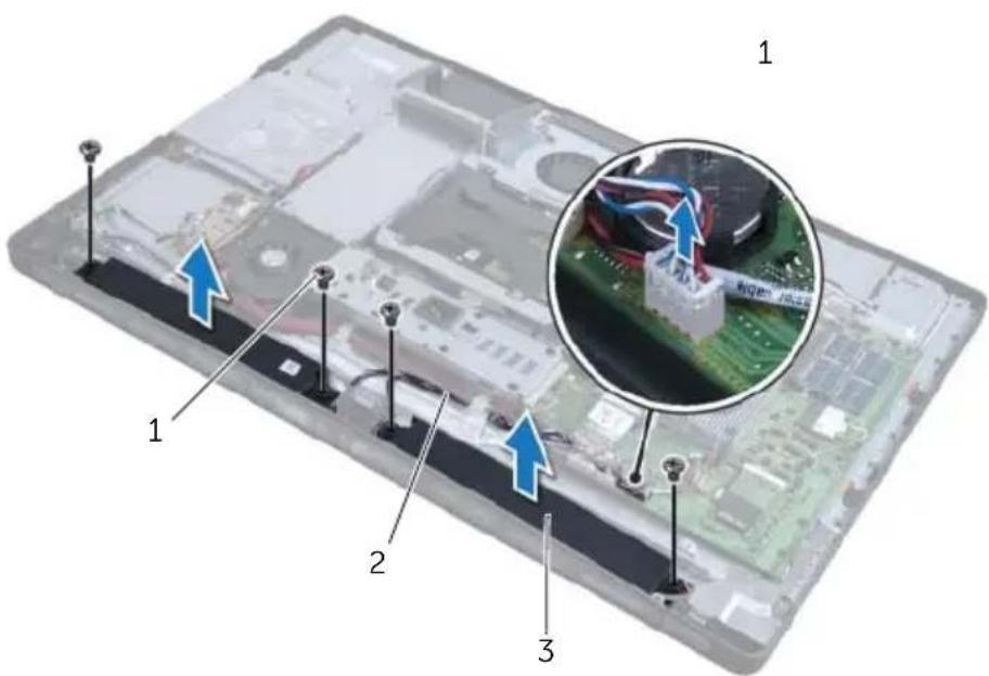
3 Remove the screws that secure the speakers to the computer base.
4 Lift the speakers off the computer base.
text_image
Laptop screen with labeled components and an inset image showing a circuit board close-up with blue arrows indicating motion or assembly.1 screws (4) 2 speakers cable
3 speakers (2)

WARNING: Before working inside your computer, read the safety information that shipped with your computer and follow the steps in "Before You Begin" on page 11. After working inside your computer, follow the instructions in "After Working Inside Your Computer" on page 13. For additional safety best practices information, see the Regulatory Compliance Homepage at dell.com/regulatory_compliance.
Procedure
1 Align the screws holes on the speakers with the screw holes on the computer base.
2 Replace the screws that secure the speakers to the computer base.
3 Route the speaker cable through the routing guides and connect the speaker cable to the system board.
Postrequisites
1 Replace the inner frame. See "Replacing the Inner Frame" on page 97.
2 Replace the trim cover. See "Replacing the Trim Cover" on page 89.
3 Replace the system-board shield. See "Replacing the System-Board Shield" on page 33.
4 Replace the back cover. See "Replacing the Back Cover" on page 21.
54
Removing the Power-Button Assembly

WARNING: Before working inside your computer, read the safety information that shipped with your computer and follow the steps in "Before You Begin" on page 11. After working inside your computer, follow the instructions in "After Working Inside Your Computer" on page 13. For additional safety best practices information, see the Regulatory Compliance Homepage at dell.com/regulatory_compliance.
Prerequisites
1 Remove the back cover. See "Removing the Back Cover" on page 19.
2 Remove the system-board shield. See "Removing the System-Board Shield" on page 31.
3 Remove the trim cover. See "Removing the Trim Cover" on page 87.
4 Remove the inner frame. See "Removing the Inner Frame" on page 95
Procedure
1 Disconnect the power-button cable from the system board.
2 Remove the power-button cable from its routing guides.
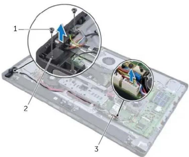
3 Remove the screws that secure the power-button assembly to the computer base.
4 Press the power button inward to release it from the slot on the computer base and then gently lift the power-button assembly off the computer base.
text_image
Laptop screen with close-up insets showing internal components and wiring, labeled 1, 2, and 3.1 screws (2) 2 power-button assembly
3 power-button cable

WARNING: Before working inside your computer, read the safety information that shipped with your computer and follow the steps in "Before You Begin" on page 11. After working inside your computer, follow the instructions in "After Working Inside Your Computer" on page 13. For additional safety best practices information, see the Regulatory Compliance Homepage at dell.com/regulatory_compliance.
Procedure
1 Place the power-button assembly in the computer base and ensure that the power button fits in the slot on the computer base.
2 Align the screw holes on the power-button assembly with the screws holes on the computer base and replace the screws that secure the power-button assembly to the computer base.
3 Route the power-button cable through the routing guides and connect the power-button cable to the system board.
Postrequisites
1 Replace the inner frame. See "Replacing the Inner Frame" on page 97.
2 Replace the trim cover. See "Replacing the Trim Cover" on page 89.
3 Replace the system-board shield. See "Replacing the System-Board Shield" on page 33.
4 Replace the back cover. See "Replacing the Back Cover" on page 21.

WARNING: Before working inside your computer, read the safety information that shipped with your computer and follow the steps in "Before You Begin" on page 11. After working inside your computer, follow the instructions in "After Working Inside Your Computer" on page 13. For additional safety best practices information, see the Regulatory Compliance Homepage at dell.com/regulatory_compliance.
Prerequisites
1 Remove the back cover. See "Removing the Back Cover" on page 19.
2 Remove the stand. See "Removing the Stand" on page 47.
3 Remove the trim cover. See "Removing the Trim Cover" on page 87.
4 Remove the I/O panel. See "Removing the I/O Panel" on page 91.
5 Remove the system-board shield. See "Removing the System-Board Shield" on page 31.
6 Remove the inner frame. See "Removing the Inner Frame" on page 95.
7 Follow step 1 to step 6 in "Removing the I/O-Board" on page 99.
8 Disconnect the antenna cables from the wireless mini-card. See "Removing the Wireless Mini-Card" on page 67.
9 Remove the processor heat-sink. See "Removing the Processor Heat-Sink" on page 79.
10 Follow step 1 to step 3 in "Removing the System Board" on page 111.
Procedure
1 Remove the screws that secure the side I/O-board shield to the computer base.
2 Remove the side I/O-board shield.
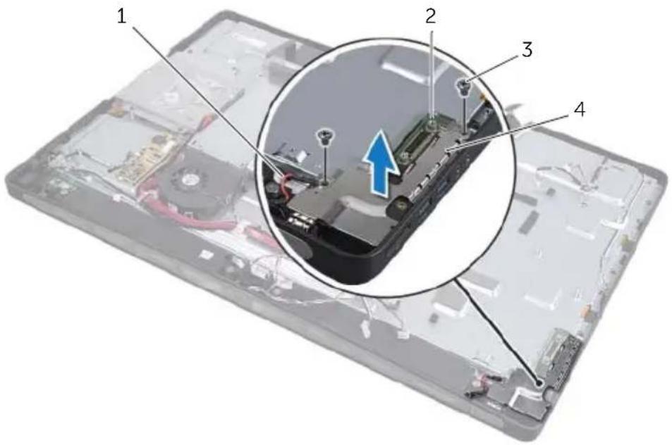
text_image
Labeled diagram of an electronic device showing internal components and a highlighted component with an upward arrow.1 grounding cable 2 side I/O-board
3 screws (2) 4 side-I/O-board shield
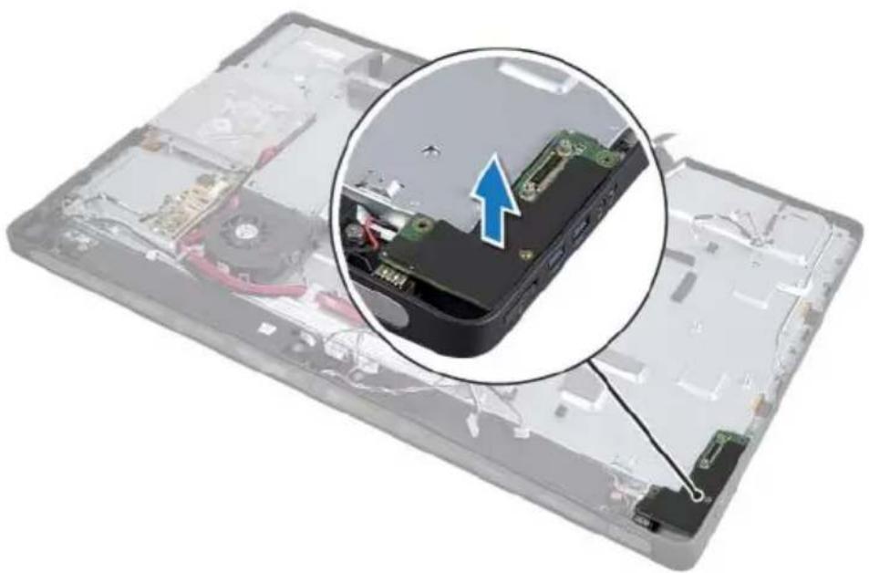
3 Gently lift the side I/O-board starting from the inner edge and then ease the ports on the side I/O-board out of the slots on the computer base.
natural_image
Close-up of an open hard disk with internal components and a magnified inset showing a device's internal structure (no text or symbols visible)
WARNING: Before working inside your computer, read the safety information that shipped with your computer and follow the steps in "Before You Begin" on page 11. After working inside your computer, follow the instructions in "After Working Inside Your Computer" on page 13. For additional safety best practices information, see the Regulatory Compliance Homepage at dell.com/regulatory_compliance.
Procedure
1 Align the screw holes on the side I/O-board with the screw holes on the computer base and gently insert the ports on the side I/O-board into the slots on the computer base.
2 Align the screw holes on the side I/O-board shield with the screw holes on the computer base and place the side I/O-board shield on the side-I/O board.
3 Replace the screws that secure the side I/O-board shield to computer base.

NOTE: Ensure that you also secure the grounding cable with the same screw that secures the side I/O-shield to the computer base.
Postrequisites
1 Follow step 1 to step 3 in "Replacing the System Board" on page 113.
2 Replace the processor heat-sink. See "Replacing the Processor Heat-Sink" on page 81.
3 Connect the antenna cables to the wireless mini-card. See "Replacing the Wireless Mini-Card" on page 69.
4 Follow step 3 to step 7 in "Replacing the I/O Board" on page 101.
5 Replace the inner frame. See "Replacing the Inner Frame" on page 97.
6 Replace the system-board shield. See "Replacing the System-Board Shield" on page 33.
7 Replace the I/O panel. See "Replacing the I/O Panel" on page 93.
8 Replace the trim cover. See "Replacing the Trim Cover" on page 89.
9 Replace the stand. See "Replacing the Stand" on page 49.
10 Replace the back cover. See "Replacing the Back Cover" on page 21.

WARNING: Before working inside your computer, read the safety information that shipped with your computer and follow the steps in "Before You Begin" on page 11. After working inside your computer, follow the instructions in "After Working Inside Your Computer" on page 13. For additional safety best practices information, see the Regulatory Compliance Homepage at dell.com/regulatory_compliance.
Prerequisites
1 Remove the back cover. See "Removing the Back Cover" on page 19.
2 Remove the stand. See "Removing the Stand" on page 47.
3 Follow step 1 to step 2 in "Removing the Hard Drive" on page 51.
4 Remove the hard-drive cage. See "Removing the Hard-Drive Cage" on page 55.
5 Follow step 1 to step 2 in "Removing the Optical Drive" on page 27.
6 Remove the trim cover. See "Removing the Trim Cover" on page 87.
7 Remove the I/O panel. See "Removing the I/O Panel" on page 91.
8 Remove the system-board shield. See "Removing the System-Board Shield" on page 31.
9 Remove the inner frame. See "Removing the Inner Frame" on page 95.
10 Follow step 1 to step 6 in "Removing the I/O-Board" on page 99.
11 Remove the processor heat-sink. See "Removing the Processor Heat-Sink" on page 79.
12 Remove the processor heat-sink fan. See "Removing the Processor Heat-Sink Fan" on page 75.
13 Remove the power-supply fan. See "Removing the Power-Supply Fan" on page 59.
14 Remove the power-supply unit. See "Removing the Power-Supply Unit" on page 35.
15 Remove the converter board. See "Removing the Converter Board" on page 23.
16 Follow step 1 to step 3 in "Removing the System Board" on page 111.
17 Remove the side I/O-board. See "Removing the Side I/O-Board" on page 123.
Procedure
1 Disconnect the display-backlight cable from the display assembly.
2 Remove the screw that secures the grounding cable to the computer base.
3 Remove the plastic shield above the LVDS and display-power cables.
4 Press the securing clips and disconnect the LVDS cable from the display assembly.
5 Disconnect the touchscreen cable from the display assembly.
6 Press the securing clip and disconnect the display-power cable from the display assembly.
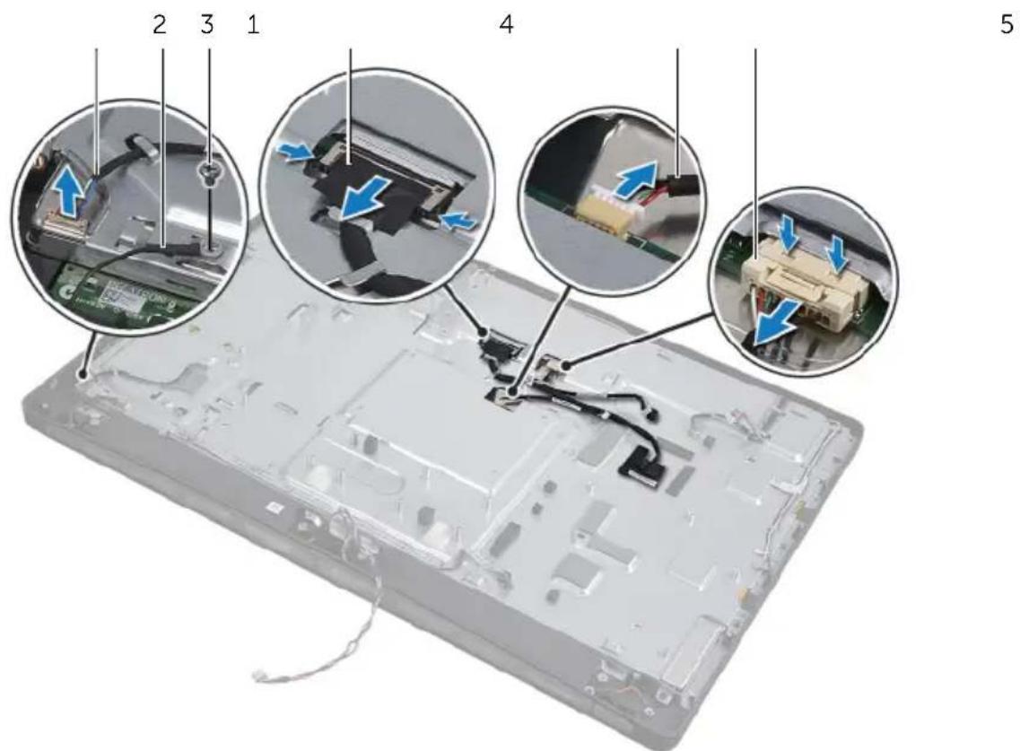
text_image
Labeled diagram of an electronic device showing internal components and cable connections, with numbered annotations for assembly or repair.1 display-backlight cable 2 grounding cable
3 grounding-cable screw 4 LVDS cable
5 touchscreen cable 6 display-power cable
7 Remove the following cables from the routing guides on the middle frame:
- LVDS cable
- Display-power cable
• Infrared-receiver cable - Camera cable
• Hard-drive power and data cable
• Optical-drive power and data cable - Converter cable
- Power-button cable
• Display-backlight cable
8 Lift the middle cover off the computer base.
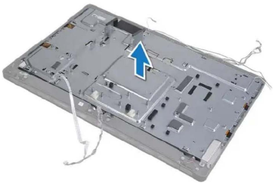
natural_image
3D rendering of an open computer chassis with visible internal components and a blue arrow pointing to a specific area (no text or symbols present)
WARNING: Before working inside your computer, read the safety information that shipped with your computer and follow the steps in "Before You Begin" on page 11. After working inside your computer, follow the instructions in "After Working Inside Your Computer" on page 13. For additional safety best practices information, see the Regulatory Compliance Homepage at dell.com/regulatory_compliance.
Procedure
1 Place the middle cover on the computer base and route the cables through their slots on the middle cover.
2 Route the following cables through their routing guides on the middle frame:
- LVDS cable
- Display-power cable
- Infrared-receiver cable
- Camera cable
- Hard-drive power and data cable
• Optical-drive power and data cable - Converter cable
- Power-button cable
- Display-backlight cable
3 Replace the plastic shield above the LVDS and display-power cables.
4 Connect the LVDS, display-power, and touchscreen cables to the display assembly.
5 Replace the screw that secures the grounding cable to the middle cover.
6 Connect the display-backlight cable to the display assembly.
Postrequisites
1 Replace the side I/O-board. See "Replacing the Side-I/O Board" on page 125.
2 Follow step 1 to step 3 in "Replacing the System Board" on page 113.
3 Replace the converter board. See "Replacing the Converter Board" on page 25.
4 Replace the power-supply unit. See "Replacing the Power-Supply Unit" on page 37.
5 Replace the power-supply fan. See "Replacing the Power-Supply Fan" on page 61.
6 Replace the processor heat-sink fan. See "Replacing the Processor Heat-Sink Fan" on page 77.
7 Replace the processor heat-sink. See "Replacing the Processor Heat-Sink" on page 81.
8 Follow step 3 to step 7 in "Replacing the I/O Board" on page 101.
9 Replace the inner frame. See "Replacing the Inner Frame" on page 97.
10 Replace the system-board shield. See "Replacing the System-Board Shield" on page 33.
11 Replace the I/O panel. See "Replacing the I/O Panel" on page 93.
12 Replace the trim cover. See "Replacing the Trim Cover" on page 89.
13 Follow step 2 to step 4 in "Replacing the Optical Drive" on page 29.
14 Replace the hard-drive cage. See "Replacing the Hard-Drive Cage" on page 57.
15 Follow step 2 to step 3 in "Replacing the Hard Drive" on page 53.
16 Replace the stand. See "Replacing the Stand" on page 49.
17 Replace the back cover. See "Replacing the Back Cover" on page 21.

WARNING: Before working inside your computer, read the safety information that shipped with your computer and follow the steps in "Before You Begin" on page 11. After working inside your computer, follow the instructions in "After Working Inside Your Computer" on page 13. For additional safety best practices information, see the Regulatory Compliance Homepage at dell.com/regulatory_compliance.
Prerequisites
1 Remove the back cover. See "Removing the Back Cover" on page 19.
2 Remove the stand. See "Removing the Stand" on page 47.
3 Remove the system-board shield. See "Removing the System-Board Shield" on page 31.
4 Remove the trim cover. See "Removing the Trim Cover" on page 87.
5 Remove the processor heat-sink fan. See "Removing the Processor Heat-Sink Fan" on page 75.
6 Remove the inner frame. See "Removing the Inner Frame" on page 95.
Procedure
1 Disconnect the power-button cable from the system board and remove the power-button cable from its routing guides.
2 Disconnect the speaker cable from the system board and remove the speaker cable from its routing guides.
3 Disconnect the antenna cables from the wireless mini-card and remove the antenna cables from their routing guides.
4 Disconnect the camera and infrared-module cables from the system board and remove the cables from their routing guides.
5 Disconnect the display-power, touchscreen, and LVDS cables from the system board.
6 Remove the plastic shield and remove the display-power, LVDS, and touchscreen cables from their routing guides.
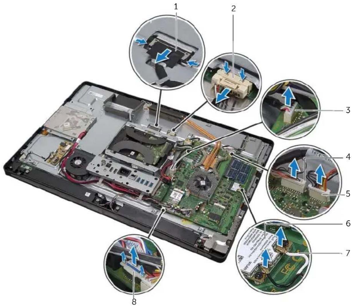
text_image
Labeled diagram of an electronic device showing internal components and wiring, with numbered annotations for each part.1 LVDS cable 2 display-power cable
3 touchscreen cable 4 camera cable
5 infrared-module cable 6 wireless mini-card
7 wireless-antenna cables (2) 8 volume/display-settings controls cable
7 Disconnect the display-backlight cable from the display assembly.
8 Remove the screw that secures the grounding cable to the processor cooling vents.
9 Remove the screw that secures the grounding cable from the right-speaker mesh to the middle cover.
10 Remove the screws that secure the system board to the side I/O-board.
11 Remove the screws that secure the side I/O-board shield to the computer base and remove the side I/O-board shield.
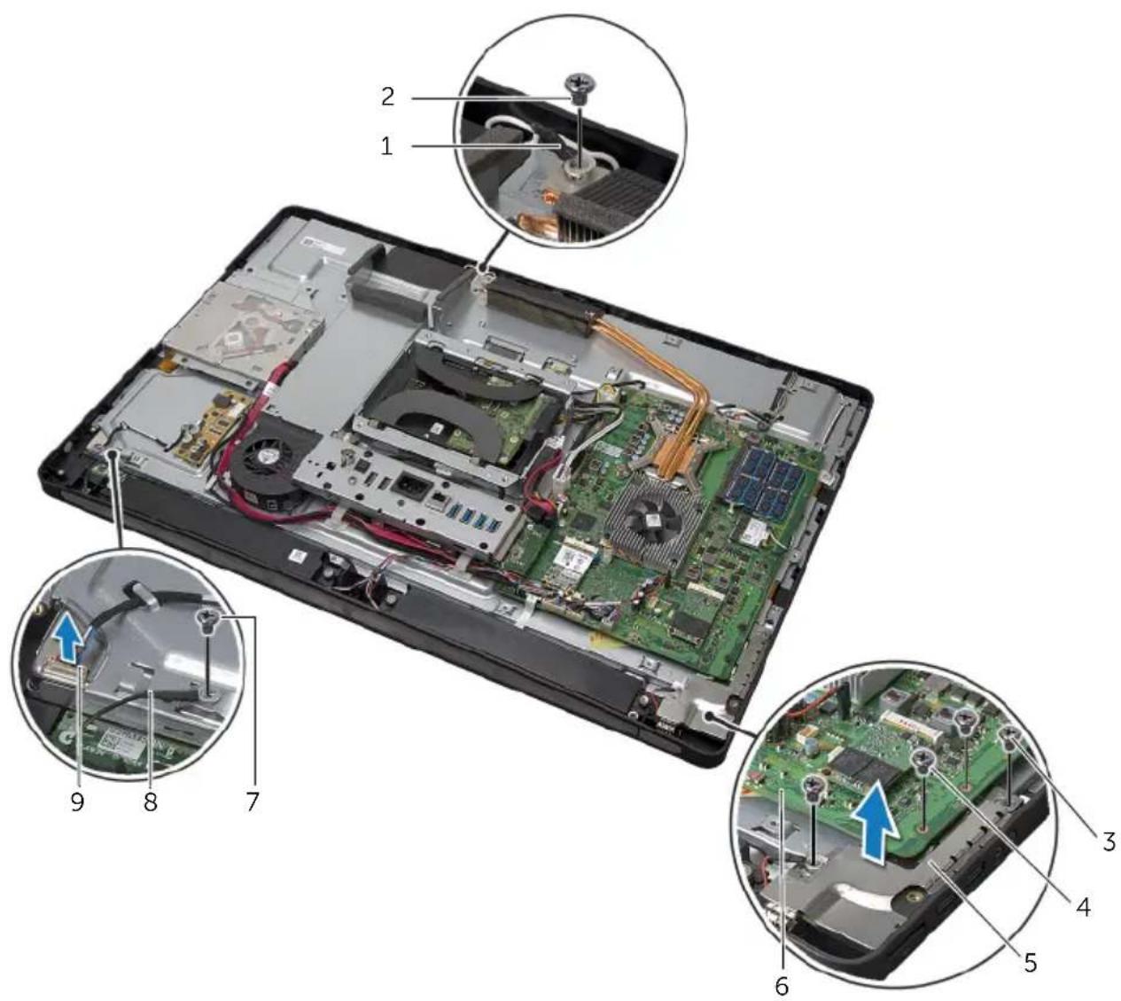
text_image
Labeled diagram of an open computer case showing internal components and parts with numbered annotations| 1 processor cooling-vents grounding cable 2 grounding-cable screw |
| 3 side I/O-board shield screws (2) 4 system-board screws (2) |
| 5 side I/O-board shield 6 system board |
| 7 grounding-cable screw 8 speaker grounding cable |
| 9 display-backlight cable |

WARNING: The middle cover is heavy when the components are attached to it. It is recommended that two people remove and replace the middle cover while the components are attached to it.
12 Using the hard-drive cage, gently lift the middle-cover assembly along with the components and ease the cables out of the slots.
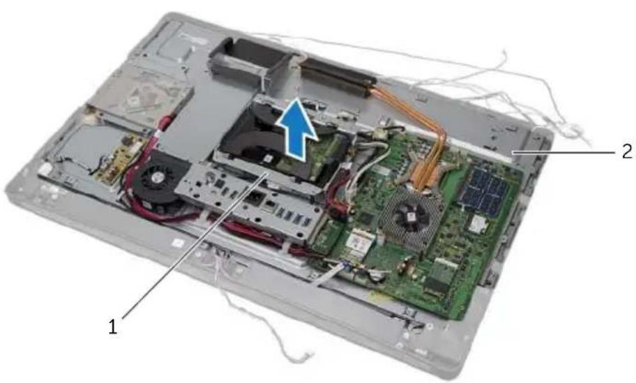
text_image
Labeled diagram of an electronic device showing internal components with numbered annotations1 hard-drive cage 2 middle-cover assembly
13 Remove the side-I/O board.
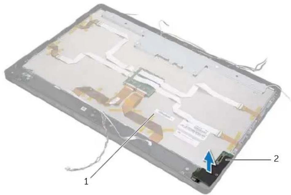
text_image
Labeled diagram of a device showing internal components with numbered annotations1 display assembly 2 side I/O board
14 Push the tabs and disconnect the ribbon cables from the display assembly.
15 Peel off the tapes securing the ribbon cables to the display assembly.
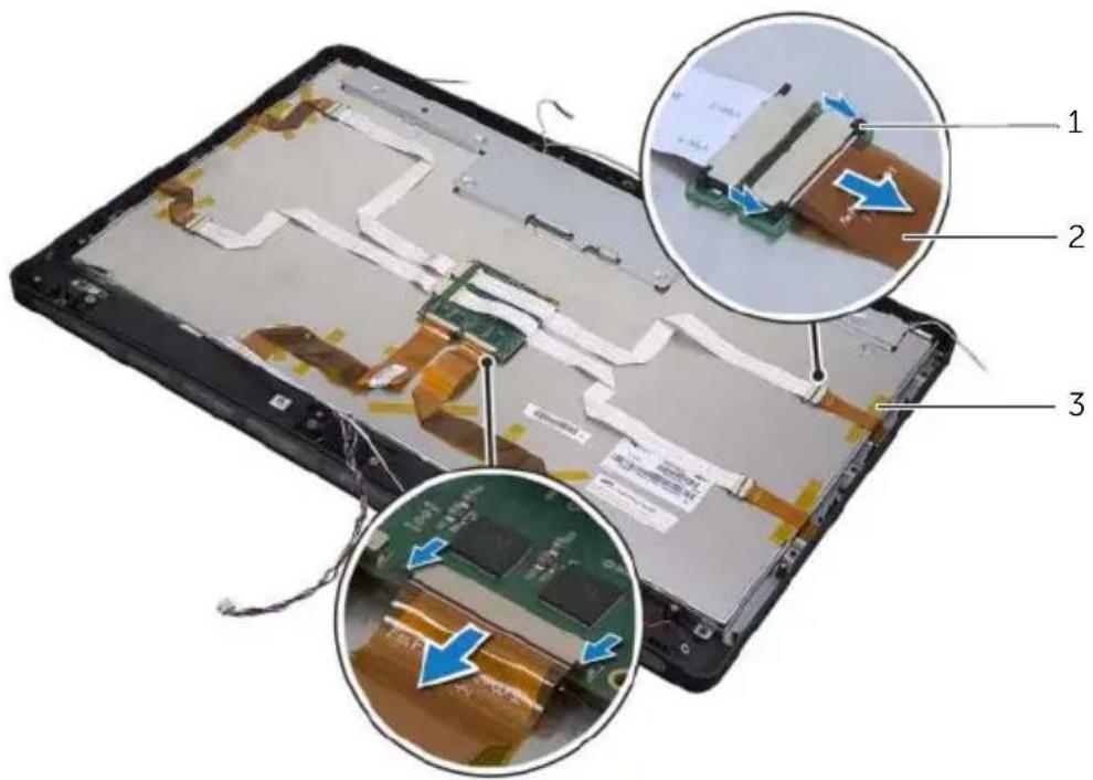
text_image
Labeled diagram of a smartphone showing internal components and parts with annotations in Chinese1 tabs 2 ribbon cables (6)
3 t a p e
16 Remove the screws that secure the display assembly to the computer base.
17 Lift the display assembly from the computer base.
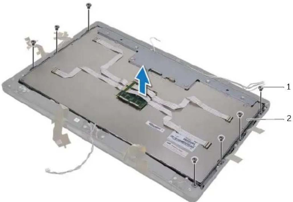
text_image
Labeled diagram of an electronic device showing internal components and a blue arrow indicating a specific area.1 screws (7) 2 display assembly
18 Remove the screws that secure the display brackets to the display panel.
19 Remove the display brackets from the display panel.
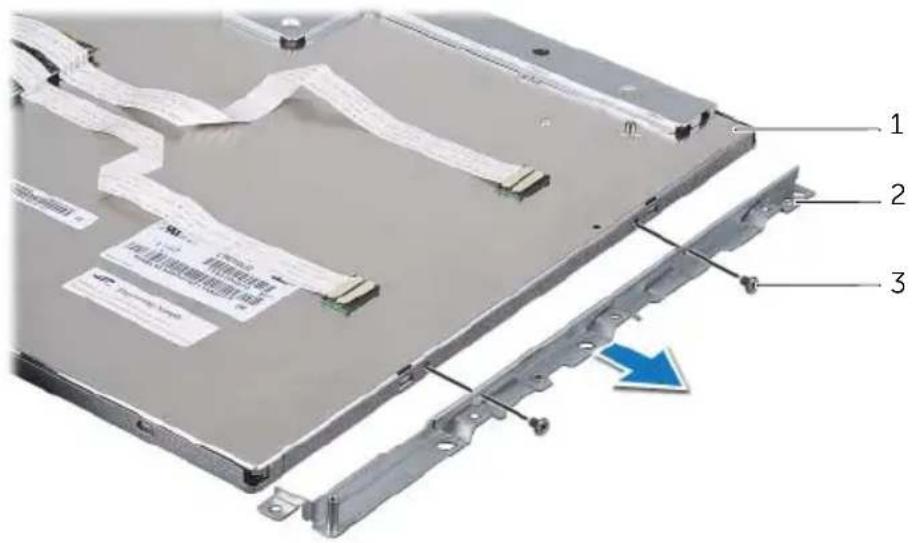
text_image
Labeled diagram of an electronic device showing internal components and a blue arrow indicating a specific area.1 display panel
2 display brackets (2)
3 screws (4)

WARNING: Before working inside your computer, read the safety information that shipped with your computer and follow the steps in "Before You Begin" on page 11. After working inside your computer, follow the instructions in "After Working Inside Your Computer" on page 13. For additional safety best practices information, see the Regulatory Compliance Homepage at dell.com/regulatory_compliance.

WARNING: The middle cover is heavy when the components are attached to it. It is recommended that two people remove and replace the middle cover while the components are attached to it.
Procedure
1 Align the screw holes on the display brackets with the screw holes on the display panel.
2 Replace the screws that secure the display brackets to the display panel.
3 Align the screw holes on the display assembly with the screws holes on the computer base and gently place the display assembly over the computer base.

NOTE: Ensure that no cables are placed under the display assembly.
4 Replace the screws that secure the display assembly to the computer base.
5 Insert the ribbon cables into their connectors and press the tabs to secure the cables.
6 Adhere the tapes that secure the ribbon cables to the display assembly.
7 Replace the side-I/O board.
8 Align the bottom of the middle cover with the computer base and lower the middle-cover assembly into the computer base.
9 Route the display-power, LVDS, and touchscreen cables through the slots in the middle cover.
10 Place the middle-cover assembly into the computer base.

NOTE: Ensure that all cables are routed through their routing guides and no cables are placed under the middle cover.
11 Align the screw holes on the middle cover with the screw holes on the computer base.
12 Replace the screws that secure the middle-cover assembly to the computer base.
13 Align the screw holes on the side I/O-board shield with the screw holes on the computer base and replace the screws that secure the side I/O-board shield to the computer base.

NOTE: Ensure that you also secure the grounding cable with the same screw that secures the side I/O-board shield to the computer base.
14 Connect the display-power, LVDS, and touchscreen cables to the system board.
15 Route the display-power, LVDS, and touchscreen cables through their routing guides and replace the plastic shield.
16 Route the camera and infrared-module cables through their routing guides and connect the cables to the system board.
17 Route the wireless-antenna cables through their routing guides and connect the antenna cables to the wireless mini-card.
18 Route the speaker cables through their routing guides and connect the speaker cable to the system board.
19 Route the power-button cable through its routing guides and connect the power-button cable to the system board.
20 Connect the display-backlight cable to the display assembly.
21 Replace the screw that secures the grounding cable to the processor cooling-vents.
22 Replace the screw that secures the grounding cable from the right-speaker mesh to the middle cover.
Postrequisites
1 Replace the inner frame. See "Replacing the Inner Frame" on page 97.
2 Replace the processor heat-sink fan. See "Replacing the Processor Heat-Sink Fan" on page 77.
3 Replace the trim cover. See "Replacing the Trim Cover" on page 89.
4 Replace the system-board shield. See "Replacing the System-Board Shield" on page 33.
5 Replace the stand. See "Replacing the Stand" on page 49.
6 Replace the back cover. See "Replacing the Back Cover" on page 21.

WARNING: Before working inside your computer, read the safety information that shipped with your computer and follow the steps in "Before You Begin" on page 11. After working inside your computer, follow the instructions in "After Working Inside Your Computer" on page 13. For additional safety best practices information, see the Regulatory Compliance Homepage at dell.com/regulatory_compliance.
Prerequisites
1 Remove the back cover. See "Removing the Back Cover" on page 19.
2 Remove the stand. See "Removing the Stand" on page 47.
3 Remove the system-board shield. See "Removing the System-Board Shield" on page 31.
4 Remove the trim cover. See "Removing the Trim Cover" on page 87.
5 Remove the processor heat-sink fan. See "Removing the Processor Heat-Sink Fan" on page 75.
6 Remove the inner frame. See "Removing the Inner Frame" on page 95.
7 Follow step 1 to step 12 in "Removing the Display Panel" on page 133.
Procedure
1 Remove the screws that secure the camera assembly to the computer base.
2 Gently lift the camera assembly and disconnect the camera cable from the camera assembly.
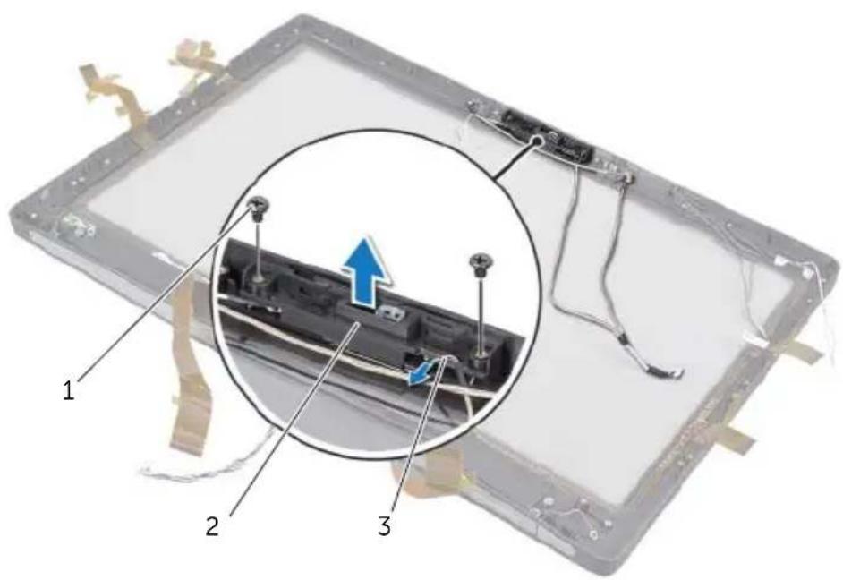
text_image
Diagram of a device's internal structure with numbered parts and an inset highlighting a component with blue arrows.1 screws (2) 2 camera assembly
3 c a m e r a c a b l e
3 Loosen the captive screw that secures the camera module and the grounding cable to the camera assembly.
4 Slide the camera module out of the camera bracket.
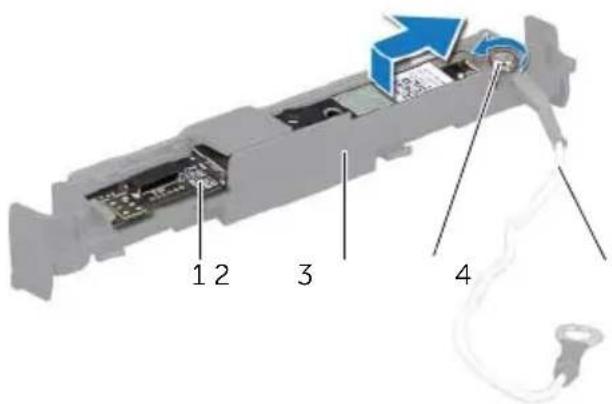
text_image
1 2 3 41 camera module 2 camera bracket
3 c a p t i v e s c r e w 4 g r o u d

WARNING: Before working inside your computer, read the safety information that shipped with your computer and follow the steps in "Before You Begin" on page 11. After working inside your computer, follow the instructions in "After Working Inside Your Computer" on page 13. For additional safety best practices information, see the Regulatory Compliance Homepage at dell.com/regulatory_compliance.
Procedure
1 Slide the camera module into the camera assembly.
2 Tighten the captive screw that secures the camera module and the grounding cable to the camera assembly.
3 Connect the camera cable to the camera assembly and place the camera in the computer base.
4 Replace the screws that secure the camera assembly to the computer base.
Postrequisites
1 Follow step 8 to step 19 in "Replacing the Display Panel" on page 139.
2 Replace the inner frame. See "Replacing the Inner Frame" on page 97.
3 Replace the processor heat-sink fan. See "Replacing the Processor Heat-Sink Fan" on page 77.
4 Replace the trim cover. See "Replacing the Trim Cover" on page 89.
5 Replace the system-board shield. See "Replacing the System-Board Shield" on page 33.
6 Replace the stand. See "Replacing the Stand" on page 49.
7 Replace the back cover. See "Replacing the Back Cover" on page 21.

WARNING: Before working inside your computer, read the safety information that shipped with your computer and follow the steps in "Before You Begin" on page 11. After working inside your computer, follow the instructions in "After Working Inside Your Computer" on page 13. For additional safety best practices information, see the Regulatory Compliance Homepage at dell.com/regulatory_compliance.
Prerequisites
1 Remove the back cover. See "Removing the Back Cover" on page 19.
2 Remove the stand. See "Removing the Stand" on page 47.
3 Remove the system-board shield. See "Removing the System-Board Shield" on page 31.
4 Remove the trim cover. See "Removing the Trim Cover" on page 87.
5 Remove the processor heat-sink fan. See "Removing the Processor Heat-Sink Fan" on page 75.
6 Remove the inner frame. See "Removing the Inner Frame" on page 95.
7 Follow step 1 to step 12 in "Removing the Display Panel" on page 133.
Procedure
1 Disconnect the microphone cables from the microphone modules.
2 Using a plastic scribe, pull the securing tabs and slide the microphone module upward.
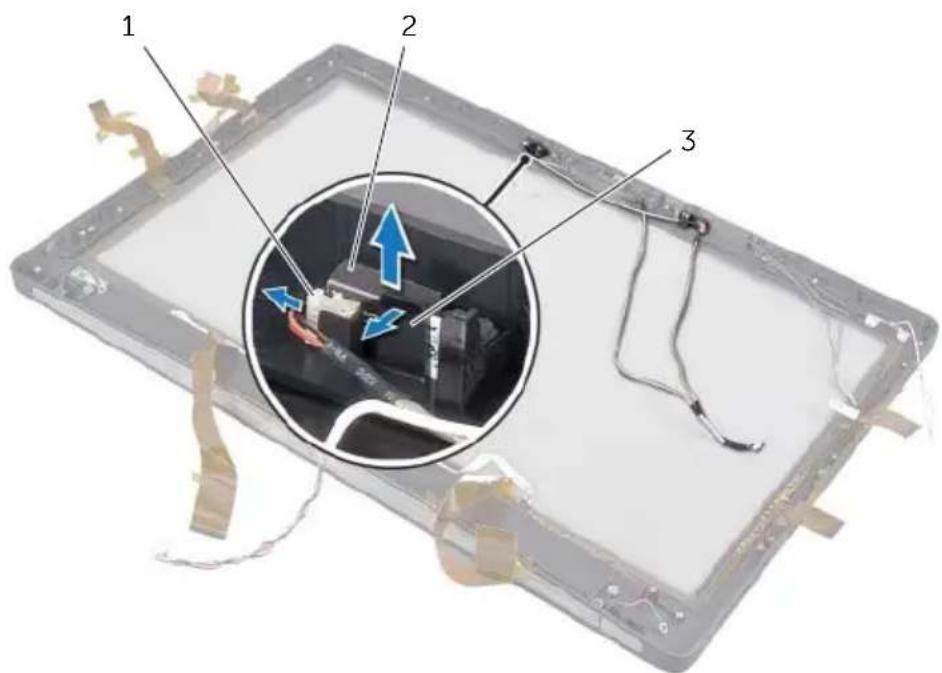
text_image
1 2 31 microphone cable 2 microphone modules (2)
3 securing tab
3 Remove the microphone module out of the microphone-module socket.

WARNING: Before working inside your computer, read the safety information that shipped with your computer and follow the steps in "Before You Begin" on page 11. After working inside your computer, follow the instructions in "After Working Inside Your Computer" on page 13. For additional safety best practices information, see the Regulatory Compliance Homepage at dell.com/regulatory_compliance.
Procedure
1 Align the microphone modules with the microphone-module socket and insert the microphone modules into the microphone-module socket. Ensure that the microphone modules are secured by the tabs on the microphone-module socket.
2 Connect the microphone cables to the microphone modules.
Postrequisites
1 Follow step 8 to step 19 in "Replacing the Display Panel" on page 139.
2 Replace the inner frame. See "Replacing the Inner Frame" on page 97.
3 Replace the processor heat-sink fan. See "Replacing the Processor Heat-Sink Fan" on page 77.
4 Replace the trim cover. See "Replacing the Trim Cover" on page 89.
5 Replace the system-board shield. See "Replacing the System-Board Shield" on page 33.
6 Replace the stand. See "Replacing the Stand" on page 49.
7 Replace the back cover. See "Replacing the Back Cover" on page 21.

WARNING: Before working inside your computer, read the safety information that shipped with your computer and follow the steps in "Before You Begin" on page 11. After working inside your computer, follow the instructions in "After Working Inside Your Computer" on page 13. For additional safety best practices information, see the Regulatory Compliance Homepage at dell.com/regulatory_compliance.
Prerequisites
1 Remove the back cover. See "Removing the Back Cover" on page 19.
2 Remove the stand. See "Removing the Stand" on page 47.
3 Remove the system-board shield. See "Removing the System-Board Shield" on page 31.
4 Remove the trim cover. See "Removing the Trim Cover" on page 87.
5 Remove the processor heat-sink fan. See "Removing the Processor Heat-Sink Fan" on page 75.
6 Remove the inner frame. See "Removing the Inner Frame" on page 95.
7 Follow step 1 to step 12 in "Removing the Display Panel" on page 133.
Procedure
1 Lift the securing tab and slide the IR receiver out of the IR-receiver socket.
2 Ease the IR-activity light out of the IR-activity light socket.
3 Remove the IR module from the computer base.
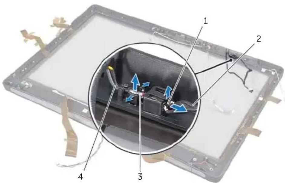
text_image
Diagram of an electronic device showing internal components with numbered labels and a magnified view highlighting internal structure.1 IR receiver 2 IR-receiver cable
3 IR-activity light 4 IR-activity light cable
67 Replacing the Infrared (IR) Module

WARNING: Before working inside your computer, read the safety information that shipped with your computer and follow the steps in "Before You Begin" on page 11. After working inside your computer, follow the instructions in "After Working Inside Your Computer" on page 13. For additional safety best practices information, see the Regulatory Compliance Homepage at dell.com/regulatory_compliance.
Procedure
1 With the sensor side facing toward the front of the computer, slide the IR receiver into the IR-receiver socket till the IR receiver locks in place.
2 With the LED facing toward the front of the computer, press the IR-activity light into the IR-activity light slot.
Postrequisites
1 Follow step 8 to step 19 in "Replacing the Display Panel" on page 139.
2 Replace the inner frame. See "Replacing the Inner Frame" on page 97.
3 Replace the processor heat-sink fan. See "Replacing the Processor Heat-Sink Fan" on page 77.
4 Replace the trim cover. See "Replacing the Trim Cover" on page 89.
5 Replace the system-board shield. See "Replacing the System-Board Shield" on page 33.
6 Replace the stand. See "Replacing the Stand" on page 49.
7 Replace the back cover. See "Replacing the Back Cover" on page 21.

WARNING: Before working inside your computer, read the safety information that shipped with your computer and follow the steps in "Before You Begin" on page 11. After working inside your computer, follow the instructions in "After Working Inside Your Computer" on page 13. For additional safety best practices information, see the Regulatory Compliance Homepage at dell.com/regulatory_compliance.
Prerequisites
1 Remove the back cover. See "Removing the Back Cover" on page 19.
2 Remove the stand. See "Removing the Stand" on page 47.
3 Remove the system-board shield. See "Removing the System-Board Shield" on page 31.
4 Remove the trim cover. See "Removing the Trim Cover" on page 87.
5 Remove the processor heat-sink fan. See "Removing the Processor Heat-Sink Fan" on page 75.
6 Remove the inner frame. See "Removing the Inner Frame" on page 95.
7 Follow step 1 to step 12 in "Removing the Display Panel" on page 133.
Procedure
1 Disconnect the wireless-antenna cables from the wireless mini-card.
2 Note the routing of the antenna cables and remove the cables from the routing guides.
3 Peel the antennas modules off the computer base.
4 Lift the antenna modules out of the computer base.
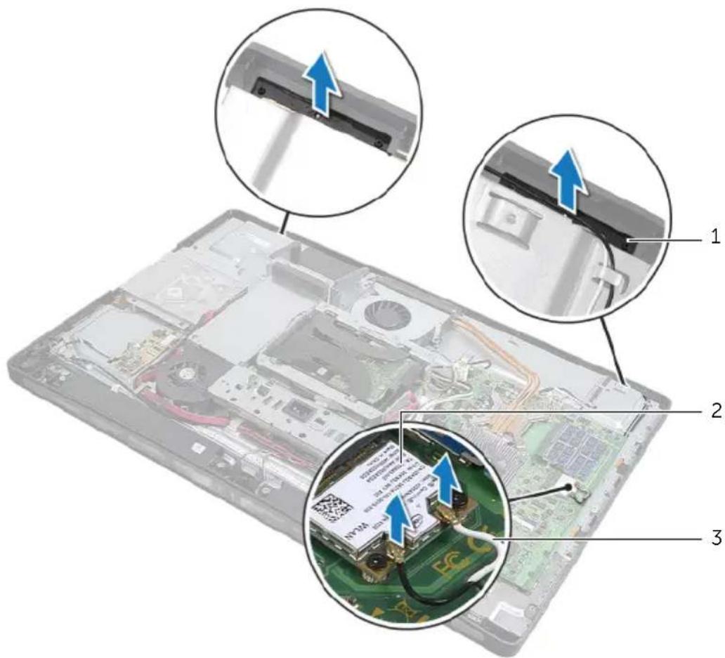
text_image
Labeled diagram of a laptop showing internal components and a QR code inserted into the circuit board, with three views (1, 2, 3) highlighting key parts.1 antenna modules (2) 2 wireless mini-card
3 wireless-antenna cables (2)

WARNING: Before working inside your computer, read the safety information that shipped with your computer and follow the steps in "Before You Begin" on page 11. After working inside your computer, follow the instructions in "After Working Inside Your Computer" on page 13. For additional safety best practices information, see the Regulatory Compliance Homepage at dell.com/regulatory_compliance.
Procedure
1 Align the antenna modules with the alignment posts on the computer base and adhere the antenna modules to the computer base.
2 Route the wireless-antenna cables through their routing guides and connect the wireless-antenna cables to the wireless mini-card.
Postrequisites
1 Follow step 8 to step 19 in "Replacing the Display Panel" on page 139.
2 Replace the inner frame. See "Replacing the Inner Frame" on page 97.
3 Replace the processor heat-sink fan. See "Replacing the Processor Heat-Sink Fan" on page 77.
4 Replace the trim cover. See "Replacing the Trim Cover" on page 89.
5 Replace the system-board shield. See "Replacing the System-Board Shield" on page 33.
6 Replace the stand. See "Replacing the Stand" on page 49.
7 Replace the back cover. See "Replacing the Back Cover" on page 21.
Overview
Use system setup to:
- Get information about the hardware installed in your computer, such as the amount of RAM, the size of the hard drive, and so on
- Change the system configuration information
- Set or change a user-selectable option, such as the user password, type of hard drive installed, enabling or disabling base devices, and so on

CAUTION: Unless you are an expert computer user, do not change the settings in the system setup program. Certain changes can make your computer work incorrectly.

NOTE: Before you change system setup, it is recommended that you write down the system setup screen information for future reference.
Entering System Setup
1 Turn on (or restart) your computer.
2 During POST, when the DELL logo is displayed, watch for the F2 prompt to appear and then press

NOTE: The F2 prompt indicates that the keyboard has initialized. This prompt can appear very quickly, so you must watch for it, and then press
System Setup Screens
The system setup screen displays current or changeable configuration information for your computer. Information on the screen is divided into three areas: the setup item, active help screen, and key functions.
| Setup Item — This field appears on the left side of the system setup window. This field is a scrollable list containing features that define the configuration of your computer, including installed hardware, power conservation, and security features.Scroll up and down the list with the up- and down-arrow keys. As an option is highlighted, the Help Screen displays more information about that option and available settings. | Help Screen — This field appears on the right side of the system setup window and contains information about each option listed in the Setup Item. In this field you can view information about your computer and make changes to your current settings.Press the up- and down-arrow keys to highlight an option. Press <Enter> to make that selection active and return to the Setup Item.NOTE: Not all settings listed in the Setup Item are changeable. |
| Key Functions — This field appears below the Help Screen and lists keys and their functions within the active system setup field. | |
System Setup Options

NOTE: Depending on your computer and installed devices, the items listed in this section may appear, or may not appear exactly as listed.
Main → System Information
BIOS Revision Display the BIOS revision.
BIOS Build Date Displays the BIOS release date.
System Name Displays the system name.
System Time (hh:mm:ss) Displays the current date.
System Date (mm:dd:yy) Displays the current time.
Service Tag Displays the Service Tag of your computer.
Service Tag Input Allows you to enter the Service Tag of your computer.
Asset Tag Displays the Asset Tag of the computer.
Main → Processor Information
| Processor Type Displays the processor type. | |
| Processor ID Displays the processor identification code. | |
| Processor Core Count | Displays the number of processor cores in your computer. |
| Processor L1 Cache Displays the processor's total L1 cache size. | |
| Processor L2 Cache Displays the processor's total L2 cache size. | |
| Processor L3 Cache Displays the processor's total L3 cache size. | |
Main → Memory Information
| Memory | Installed | Displays the total memory (RAM) installed in your computer. |
| Memory | Available | Displays the amount of memory (RAM) available on your computer. |
| Memory | Running Speed | Displays the running speed of the memory (RAM) in your computer. |
| Memory | Technology | Displays the type of memory (RAM) technology used in your computer. |
Main → SATA Information
| SATA 1 | |
| Device Type Displays the type of device connected. | |
| Device ID Displays the device identification code. | |
| Device Size Displays the size of the SATA device present in your computer. | |
| SATA 2 | |
| Device Type Displays the type of device connected. | |
| Device ID Displays the device identification code. | |
| Device Size Displays the size of the SATA device present in your computer. |
Advanced → CPU Feature
| Intel (R) Hyper-Threading Technology | If enabled, each physical processor core appears as two logical processor cores. |
| Intel (R) SpeedStep Technology | If enabled, the processor clock speed and core voltage are adjusted dynamically based on the processor load. |
| Intel (R) Virtualization Technology | If enabled, a Virtual Machine Monitor (VMM) will be able to access your computer. |
CPU XD Support If enabled, will allow your computer to use Executive Display (XD) to hinder software that exploits buffer overflows.
Limit CPUID Value If enabled, limits the maximum value the processor CPUID function will support.
Multi Core Support If enabled, allows your computer to use all cores available in the processor.
Intel(R) Turbo Boost Technology If enabled, allows your computer to use turbo boost when required.
Advanced → USB Configuration
Rear USB Ports Allows you to enable or disable the USB ports at the back of your computer.
Side USB Ports Allows you to enable or disable the USB ports at the side of your computer.
Advanced → Onboard Device Configuration
Onboard Audio Controller Allows you to enable or disable the onboard audio controller.
SATA Mode Allows you to configure the integrated hard drive controller to ATA or AHCI.
Onboard LAN Controller Allows you to enable or disable the onboard LAN controller.
Onboard LAN boot ROM Allows you to enable or disable the ROM of the onboard LAN controller.
Boot
Numlock Key Select power-on state for numlock.
Keyboard Errors Displays keyboard related errors during boot.
USB Boot Support Allows you to enable or disable boot from USB mass-storage devices.
Boot Mode Allows you to select the type of boot
1st Boot Displays the first boot device.
2nd Boot Displays the second boot device.
3rd Boot Displays the third boot device.
4th Boot Displays the fourth boot device.
5th Boot Displays the fifth boot device.
Power
| Wake Up by Integrated LAN/WLAN | If enabled, will wake the system using a network message |
| AC Recovery | Allows you to select the action the computer takes when power is restored. |
| DeepSx Power Policies Allows you to configure the DeepSx mode. | |
| USB PowerShare in S4/S5 State | Allows you to charge USB devices when the computer is in S4/S5 state. |
| USB PowerShare in Sleep State | Allows you to charge USB devices when the computer is in sleep state, but the wake-up function is disabled. |
| Auto Power On Allows the computer to start up automatically at a pre-configured time. | |
| Auto Power On Mode Allows you to set the auto power-on mode. | |
| Auto Power On Date Allows you to set the auto power-on date. | |
| Auto Power On Time Allows you to set the auto power-on time. | |
Security
| Supervisor Password Displays the status of the supervisor password. |
| User Password Allows you to change the user password. You cannot use the user password to enter the BIOS setup during POST. |
| Set Supervisor Password Allows you to set a supervisor password. |
| User Access Level Allows you to set the user-access level. |
| Set User Password Allows you to set a user password. |
| Password Check Allows you to configure when the computer prompts for passwords. (When entering system setup or at every boot) |
Exit
| Save Changes and Reset Allows you to save the changes. |
| Discard Changes and Reset Allows you to discard the changes. |
| Load Default Allows you to load the default BIOS settings. |
Changing Boot Sequence
Changing Boot Sequence for the Current Boot
You can use this feature to change the current boot sequence, for example, to boot from the optical drive to run Dell Diagnostics from the Drivers and Utilities disc. The previous boot sequence is restored at the next boot.
1 If you are booting from a USB device, connect the USB device to a USB port.
2 Turn on (or restart) your computer.
3 When F2 Setup, F12 Boot Options appears in the lower-right corner of the screen, press

NOTE: If you wait too long and the operating system logo appears, continue to wait until you see the operating system's desktop. Then shut down your computer and try again.
The Boot Device Menu appears, listing all available boot devices.
4 On the Boot Device Menu choose the device you want to boot from.
For example, if you are booting to a USB memory key, highlight USB Storage Device and press
Changing Boot Sequence for Future Boots
1 Enter system setup. See "Entering System Setup" on page 157.
2 Use the arrow keys to highlight the Boot menu option and press

NOTE: Write down your current boot sequence in case you want to restore it.
3 Press the up- and down-arrow keys to move through the list of devices.
4 Press plus (+) or minus (−) to change the boot priority of the device.
Clearing Forgotten Passwords

WARNING: Before working inside your computer, read the safety information that shipped with your computer and follow the steps in "Before You Begin" on page 11. After working inside your computer, follow the instructions in "After Working Inside Your Computer" on page 13. For additional safety best practices information, see the Regulatory Compliance Homepage at dell.com/regulatory_compliance.
1 Remove the back cover. See "Removing the Back Cover" on page 19.
2 Remove the system-board shield. See "Removing the System-Board Shield" on page 31.
3 Locate the password-reset jumper on the system board. See "System-Board Components" on page 16.
4 Remove the 2-pin jumper plug from pins 2 and 3 and fix it on pins 1 and 2.
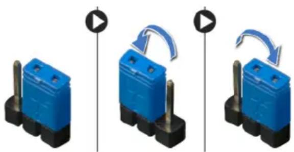
natural_image
Three blue electrical component blocks with black pins, shown in sequence with directional arrows indicating rotation (no text or symbols)5 Wait for approximately five seconds to clear the password setting.
6 Remove the 2-pin jumper plug from pins 1 and 2 and replace it on pins 2 and 3.
7 Replace the system-board shield. See "Replacing the System-Board Shield" on page 33.
8 Replace the back cover. See "Replacing the Back Cover" on page 21.
Clearing CMOS Settings

WARNING: Before working inside your computer, read the safety information that shipped with your computer and follow the steps in "Before You Begin" on page 11. After working inside your computer, follow the instructions in "After Working Inside Your Computer" on page 13. For additional safety best practices information, see the Regulatory Compliance Homepage at dell.com/regulatory_compliance.
1 Remove the back cover. See "Removing the Back Cover" on page 19.
2 Remove the system-board shield. See "Removing the System-Board Shield" on page 31.
3 Locate the CMOS reset jumper on the system board. See "System-Board Components" on page 16.
4 Remove the 2-pin jumper plug from pins 2 and 3 and fix it on pins 1 and 2.
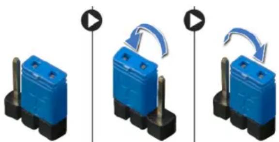
natural_image
Three blue plastic electronic components with black bases, shown in sequence with triangular loading indicators (no text or symbols)5 Wait for approximately five seconds to clear the CMOS setting.
6 Remove the 2-pin jumper plug from pins 1 and 2 and replace it on pins 2 and 3.
7 Replace the system-board shield. See "Replacing the System-Board Shield" on page 33.
8 Replace the back cover. See "Replacing the Back Cover" on page 21.
You may need to flash the BIOS when an update is available or after replacing the system board. To flash the BIOS:
1 Turn on the computer.
2 Go to support.dell.com/support/downloads.
3 Locate the BIOS update file for your computer:

NOTE: The Service Tag for your computer is located on a label at the back of your computer. For more information, see the Quick Start Guide that shipped with your computer.
If you have your computer's Service Tag or Express Service Code:
a Enter your computer's Service Tag or Express Service Code in the Service Tag or Express Service Code field.
b Click Submit and proceed to step 4.
If you do not have your computer's Service Tag or Express Service Code:
a Select one of the following options:
• Automatically detect my Service Tag for me
- Choose from My Products and Services List
- Choose from a list of all Dell products
b Click Continue and follow the instructions on the screen.
4 A list of results appears on the screen. Click BIOS.
5 Click Download File to download the latest BIOS file.
6 In the Please select your download method below window, click For Single File Download via Browser, and then click Download Now.
The File Download window appears.
7 In the Save As window, select an appropriate location to download the file on your computer.
8 If the Download Complete window appears, click Close.
9 Navigate to the folder where you downloaded the BIOS update file.
10 Double-click the BIOS update file icon and follow the instructions that appear on the screen.