
Latitude E6420 ATG - Laptop DELL - Free user manual and instructions
Find the device manual for free Latitude E6420 ATG DELL in PDF.


| Product Type | Rugged Laptop |
| Brand | Dell |
| Model | Latitude E6420 ATG |
| Display Size | 14.0 inches |
| Display Type | WLED, 1366x768 pixels, up to 730 nits brightness |
| Processor | Intel Core i3, i5, or i7 (2nd gen, up to 6MB cache) |
| Memory | Up to 8GB DDR3 SDRAM (1333MHz), 2 SODIMM slots |
| Storage | Hard drive (SATA) optional optical drive |
| Graphics | Integrated Intel HD Graphics 3000 or discrete NVIDIA NVS 4200M (512MB DDR3) |
| Dimensions (W x D x H) | 357.3 x 246.5 x 29.0-37.7 mm (14.07 x 9.70 x 1.14-1.48 in) |
| Weight | Approximately 2.69 kg (5.93 lb) with 6-cell battery |
| Power Supply | 90W AC adapter, 100-240VAC, 50-60Hz |
| Battery | 6-cell or 9-cell smart lithium-ion (11.1V), ExpressCharge |
| Operating Temperature | 0°C to 60°C (32°F to 140°F) |
| Wireless | WLAN, WWAN, Bluetooth (optional) |
| Ports | USB 2.0 (4), eSATA/USB, VGA, HDMI, RJ-45, audio, memory card reader |
| Keyboard | 86/87/90 keys (QWERTY/AZERTY/Kanji), spill-resistant |
| Rugged Features | ATG handle, port covers, reinforced chassis |
| Security | TPM, Computrace, password protection, smart card reader (optional) |
| Maintenance | User-serviceable: battery, memory, hard drive, wireless cards, etc. |
| Environmental Compliance | G1 as per ISA-71.04 |
Frequently Asked Questions - Latitude E6420 ATG DELL
User questions about Latitude E6420 ATG DELL
0 question about this device. Answer the ones you know or ask your own.
Ask a new question about this device
Download the instructions for your Laptop in PDF format for free! Find your manual Latitude E6420 ATG - DELL and take your electronic device back in hand. On this page are published all the documents necessary for the use of your device. Latitude E6420 ATG by DELL.
USER MANUAL Latitude E6420 ATG DELL
Dell Latitude E6420 and E6420 ATG Owner's Manual
Notes, Cautions, and Warnings

NOTE: A NOTE indicates important information that helps you make better use of your computer.

CAUTION: A CAUTION indicates potential damage to hardware or loss of data if instructions are not followed.

WARNING: A WARNING indicates a potential for property damage, personal injury, or death.
Information in this publication is subject to change without notice.
© 2011 Dell Inc. All rights reserved.
Reproduction of these materials in any manner whatsoever without the written permission of Dell Inc. is strictly forbidden.
Trademarks used in this text: Dell™, the DELL logo, Dell Precision™, Precision ON™, ExpressCharge™, Latitude™, Latitude ON™, OptiPlex™, Vostro™, and Wi-Fi Catcher™ are trademarks of Dell Inc. Intel®, Pentium®, Xeon®, Core™, Atom™, Centrino®, and Celeron® are registered trademarks or trademarks of Intel Corporation in the U.S. and other countries. AMD® is a registered trademark and AMD Opteron™, AMD Phenom™, AMD Sempron™, AMD Athlon™, ATI Radeon™, and ATI FirePro™ are trademarks of Advanced Micro Devices, Inc. Microsoft®, Windows®, MS-DOS®, Windows Vista®, the Windows Vista start button, and Office Outlook® are either trademarks or registered trademarks of Microsoft Corporation in the United States and/or other countries. Blu-ray Disc™ is a trademark owned by the Blu-ray Disc Association (BDA) and licensed for use on discs and players. The Bluetooth®word mark is a registered trademark and owned by the Bluetooth® SIG, Inc. and any use of such mark by Dell Inc. is under license. Wi-Fi® is a registered trademark of Wireless Ethernet Compatibility Alliance, Inc.
Other trademarks and trade names may be used in this publication to refer to either the entities claiming the marks and names or their products, Dell Inc. disclaims any proprietary interest in trademarks and trade names other than its own.
2011-07
Rev. A00
Contents
Notes, Cautions, and Warnings....2
1 Working on Your Computer....9
Before Working Inside Your Computer....9
Recommended Tools....10
Turning Off Your Computer....11
After Working Inside Your Computer....11
2 ATG Handle....13
Removing The ATG Handle....13
Installing The ATG Handle....14
3 ATG Port Cover....15
Removing the ATG Port Cover....15
Installing The ATG Port Cover....16
4 Modem Connector Plug....17
Removing the Modem Connector Plug....17
Installing the Modem Connector Plug....18
5 ExpressCard....19
Removing the ExpressCard....19
Installing the ExpressCard....19
6 Battery....21
Removing the Battery....21
Installing the Battery....22
7 Subscriber Identity Module (SIM) Card....23
Removing the Subscriber Identity Module (SIM) Card....23
Installing the Subscriber Identity Module (SIM) Card....24
8 Secure Digital (SD) Card....25
Removing the Secure Digital (SD) Card....25
Installing the Secure Digital (SD) Card....25
9 Base Cover....27
Removing the Base Cover....27
Installing the Base Cover....28
10 Hard Drive....29
Removing the Hard Drive....29
Installing the Hard Drive....30
11 Optical Drive....31
Removing The Optical Drive....31
Installing the Optical Drive....34
12 Memory Card....35
Removing the Memory Card....35
Installing the Memory Card....36
13 Wireless Local Area Network (WLAN) Card....37
Removing the Wireless Local Area Network (WLAN) Card....37
Installing the Wireless Local Area Network (WLAN) Card....39
14 Wireless Wide Area Network (WWAN) Card....41
Removing the Wireless Wide Area Network (WWAN) Card....41
Installing the Wireless Wide Area Network (WWAN) Card....43
15 Coin-Cell Battery....45
Removing the Coin-Cell Battery....45
Installing the Coin-Cell Battery....46
16 Heat Sink....47
Removing The Heat Sink....47
Installing The Heat Sink....49
17 Bluetooth Card....51
Removing the Bluetooth Card....51
Installing the Bluetooth Card....53
18 Keyboard Trim....55
Removing the Keyboard Trim....55
Installing the Keyboard Trim....56
19 Keyboard....57
Removing the Keyboard....57
Installing the Keyboard....60
20 Modem Card....61
Removing the Modem Card....61
Installing the Modem Card....63
21 Palm Rest....65
Removing the Palm Rest Assembly....65
Installing the Palm Rest Assembly....68
22 Smart Card Reader....69
Removing the Smart Card....69
Installing the Smart Card....71
23 Media Board....73
Removing The Media Board....73
Installing the Media Board....75
24 ExpressCard Cage....77
Removing the ExpressCard Cage....77
Installing the ExpressCard Cage....78
25 System Board Components....79
Removing the System Board....79
Installing the System Board....84
26 Speaker....85
Removing the Speakers....85
Installing the Speakers....87
27 Modem Connector....89
Removing the Modem Connector....89
Installing the Modem Connector....93
28 Input/Output Panel....95
Removing the Input/Output (I/O) Board....95
Installing the Input/Output (I/O) Board....97
29 DC-In Port....99
Removing DC-in Port....99
Installing DC-In Port....102
30 Display Assembly....103
Removing the Display Assembly....103
Installing the Display Assembly....106
31 Display Hinges....107
Removing the Display Hinge Covers....107
Installing the Display Hinge Covers....110
32 Display Bezel....111
Removing the Display Bezel....111
Installing the Display Bezel....112
33 Display Panel....113
Removing the Display Panel....113
Installing the Display Panel....115
34 Display Bracket....117
Removing the Display Bracket....117
Installing the Display Bracket....117
35 Camera....119
Removing the Camera....119
Installing the Camera....120
36 Specifications....121
Technical Specifications....121
37 System Setup....129
Setup Overview....129
Entering System Setup....129
System Setup Menu....129
38 Diagnostics....141
Diagnostic LED Codes....141
Battery Status Lights....142
Device Status Lights....143
39 Contacting Dell....145
Contacting Dell....145
Working on Your Computer 1
Before Working Inside Your Computer
Use the following safety guidelines to help protect your computer from potential damage and to help to ensure your personal safety. Unless otherwise noted, each procedure included in this document assumes that the following conditions exist:
- You have performed the steps in Working on Your Computer.
- You have read the safety information that shipped with your computer.
- A component can be replaced or--if purchased separately--installed by performing the removal procedure in reverse order.

WARNING: Before working inside your computer, read the safety information that shipped with your computer. For additional safety best practices information, see the Regulatory Compliance Homepage at www.dell.com/regulatory_compliance.

CAUTION: Many repairs may only be done by a certified service technician. You should only perform troubleshooting and simple repairs as authorized in your product documentation, or as directed by the online or telephone service and support team. Damage due to servicing that is not authorized by Dell is not covered by your warranty. Read and follow the safety instructions that came with the product.

CAUTION: To avoid electrostatic discharge, ground yourself by using a wrist grounding strap or by periodically touching an unpainted metal surface, such as a connector on the back of the computer.

CAUTION: Handle components and cards with care. Do not touch the components or contacts on a card. Hold a card by its edges or by its metal mounting bracket. Hold a component such as a processor by its edges, not by its pins.

CAUTION: When you disconnect a cable, pull on its connector or on its pull-tab, not on the cable itself. Some cables have connectors with locking tabs; if you are disconnecting this type of cable, press in on the locking tabs before you disconnect the cable. As you pull connectors apart, keep them evenly aligned to avoid bending any connector pins. Also, before you connect a cable, ensure that both connectors are correctly oriented and aligned.

NOTE: The color of your computer and certain components may appear differently than shown in this document.
To avoid damaging your computer, perform the following steps before you begin working inside the computer.
- Ensure that your work surface is flat and clean to prevent the computer cover from being scratched.
- Turn off your computer (see Turning Off Your Computer).
- If the computer is connected to a docking device (docked) such as the optional Media Base or Battery Slice, undock it.

CAUTION: To disconnect a network cable, first unplug the cable from your computer and then unplug the cable from the network device.
- Disconnect all network cables from the computer.
- Disconnect your computer and all attached devices from their electrical outlets.
- Close the display and turn the computer upside-down on a flat work surface.

NOTE: To avoid damaging the system board, you must remove the main battery before you service the computer.
- Remove the main battery.
- Turn the computer top-side up.
- Open the display.
- Press the power button to ground the system board.

CAUTION: To guard against electrical shock, always unplug your computer from the electrical outlet before opening the display.

CAUTION: Before touching anything inside your computer, ground yourself by touching an unpainted metal surface, such as the metal at the back of the computer. While you work, periodically touch an unpainted metal surface to dissipate static electricity, which could harm internal components.
- Remove any installed ExpressCards or Smart Cards from the appropriate slots.
Recommended Tools
The procedures in this document may require the following tools:
- Small flat-blade screwdriver
-
0 Phillips screwdriver
-
1 Phillips screwdriver
- Small plastic scribe
- Flash BIOS update program CD
Turning Off Your Computer

CAUTION: To avoid losing data, save and close all open files and exit all open programs before you turn off your computer.
- Shut down the operating system:
- In Windows Vista :
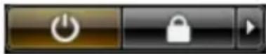
Click Start 📋, then click the arrow in the lower-right corner of the Start menu as shown below, and then click Shut Down.
- In Windows XP:
Click Start → Turn Off Computer → Turn Off. The computer turns off after the operating system shutdown process is complete.
- Ensure that the computer and all attached devices are turned off. If your computer and attached devices did not automatically turn off when you shut down your operating system, press and hold the power button for about 4 seconds to turn them off.
After Working Inside Your Computer
After you complete any replacement procedure, ensure you connect any external devices, cards, and cables before turning on your computer.

CAUTION: To avoid damage to the computer, use only the battery designed for this particular Dell computer. Do not use batteries designed for other Dell computers.
- Connect any external devices, such as a port replicator, battery slice, or media base, and replace any cards, such as an ExpressCard.
- Connect any telephone or network cables to your computer.
CAUTION: To connect a network cable, first plug the cable into the network device and then plug it into the computer.
- Replace the battery.
- Connect your computer and all attached devices to their electrical outlets.
- Turn on your computer.
ATG Handle 2
Removing The ATG Handle
- Follow the procedures in Before Working On Your Computer.
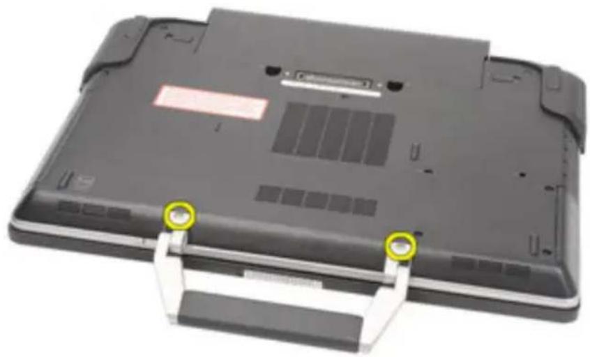
- Remove the screws that secure the ATG handle to the computer.
natural_image
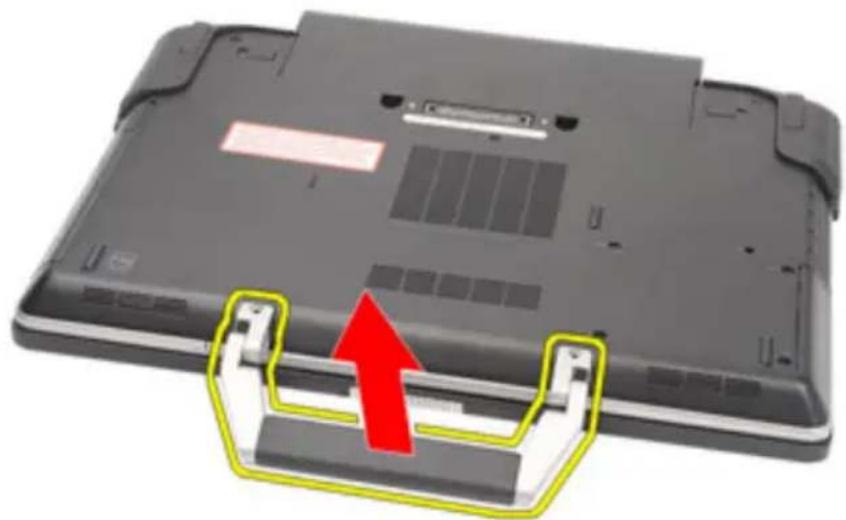
Laptop back with two yellow-green circular markers on the side (no text or symbols visible)- Remove the ATG handle out of the computer.
natural_image
Laptop back with a red upward arrow indicating a fold or change, showing internal components and mounting brackets (no text or symbols visible)Installing The ATG Handle
- Place the ATG handle and tighten the screws that secure it to the computer.
- Follow the procedures in After working inside your computer.
ATG Port Cover 3
Removing the ATG Port Cover
-
Follow the procedures in Before Working On Your Computer.
-
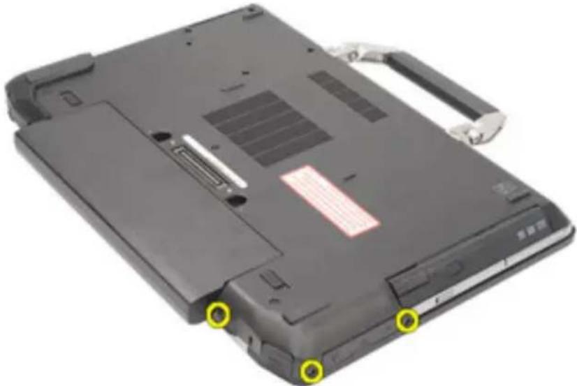
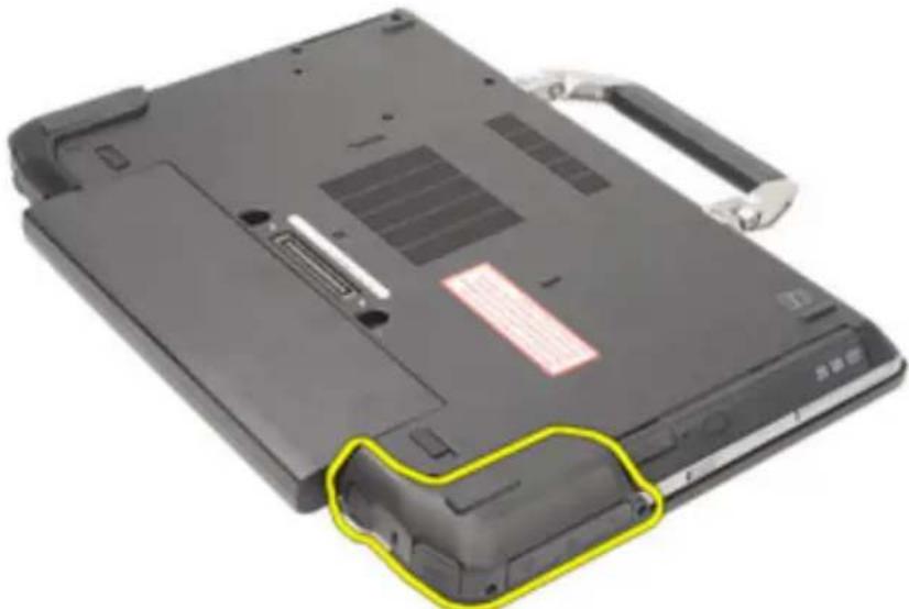
Remove the screws on the right ATG Port Cover.
natural_image
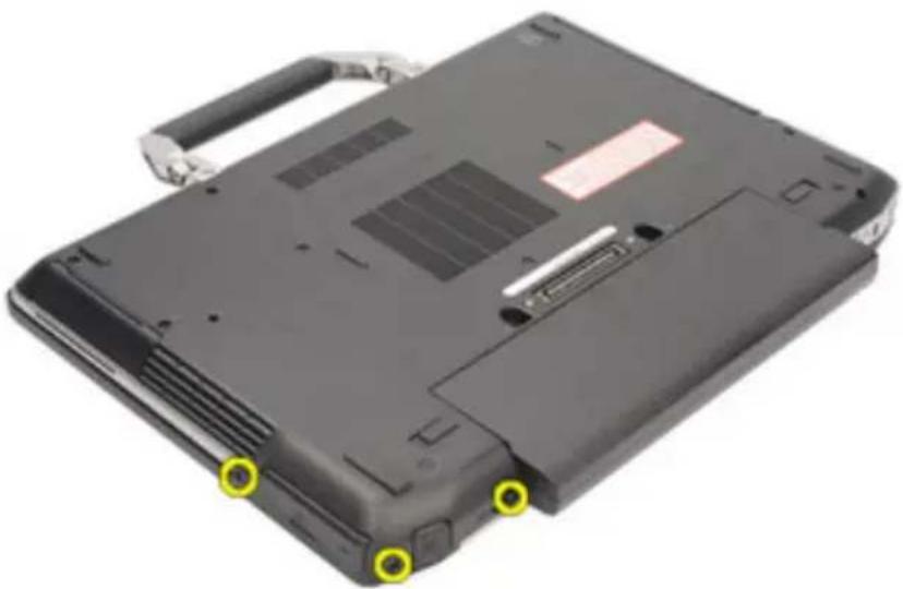
Black laptop cover with visible slots and a red tab, showing two yellow circular markers on the front panel (no text or symbols on the cover itself)- Remove the right ATG port cover.
natural_image
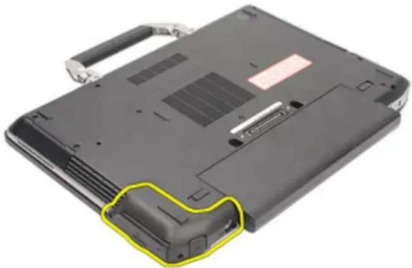
Laptop back panel with visible internal components and a highlighted yellow outline (no text or symbols)- Remove the screws on the left ATG port cover.
natural_image
Black laptop case with visible rear panel and two yellow circular markers on the front edge (no text or symbols)- Remove the left ATG Port Cover.
natural_image
Laptop back with a highlighted yellow-green portion, showing internal components and no visible text or symbols.Installing The ATG Port Cover
- Place the ATG Port Covers and tighten the screws that secure it to the computer.
- Follow the procedures in After working inside your computer.
Modem Connector Plug 4
Removing the Modem Connector Plug
- Follow the procedures in Before Working On Your Computer.
- Remove the battery.
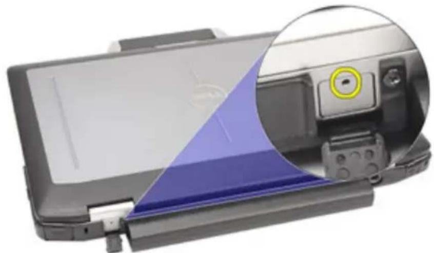
- Pop open the rubber cover.
- Identify the pin hole.
natural_image
Close-up of a printer's front panel and close-up of its internal device, showing no visible text or symbols.- Insert a pin into the hole and pull the pin upwards to release the latch cover.
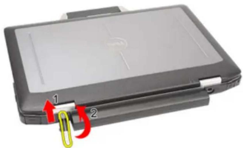
natural_image
Black electronic device with a paperclip inserted into its tray, showing red and yellow arrows indicating movement (no text or symbols)- Remove the cover.
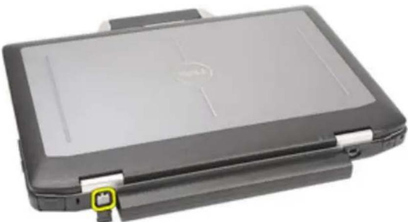
natural_image
Black hardcover device with a flat screen and a small logo, no visible text or symbols on the body.Installing the Modem Connector Plug
- Place the modem cover.
- Identify the pin hole and insert a pin into the hole and pull the pin to lock the cover.
- Lock the rubber cover.
- Install the Battery.
- Follow the procedures in After Working Inside Your Computer.
ExpressCard 5
Removing the ExpressCard
-
Follow the procedures in Before Working On Your Computer.
-
Press in on the ExpressCard to release it from the computer.
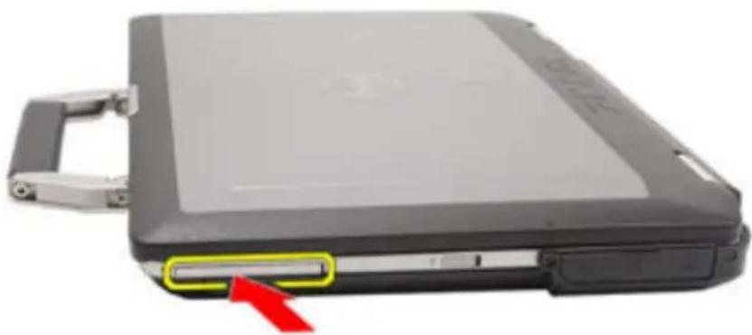
natural_image
Close-up of a black hard disk device with a red arrow pointing to a slot, no visible text or symbols.- Slide the ExpressCard out of the computer.
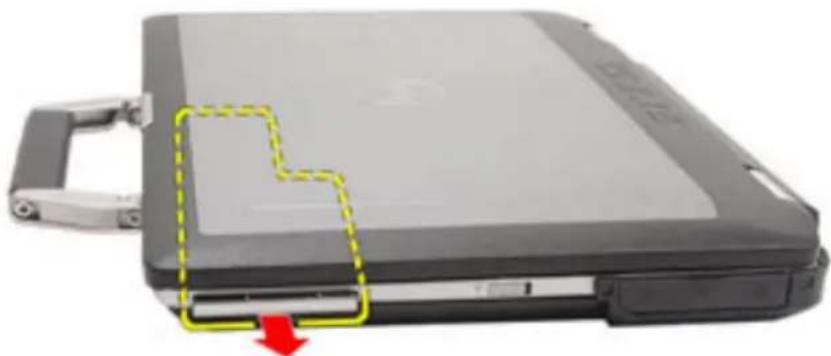
natural_image
Close-up of a gray hard disk with a yellow dashed outline and red arrow indicating a location or movement (no text or symbols visible)Installing the ExpressCard
-
Slide the ExpressCard into its slot until it clicks into place.
-
Follow the procedures in After working inside your computer.
Battery 6
Removing the Battery
-
Follow the procedures in Before Working On Your Computer.
-
Slide the battery latches toward the unlock position.
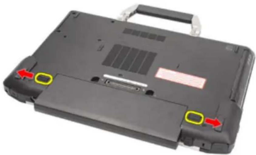
natural_image
Black laptop case with red arrows pointing to two yellow button areas (no text or symbols visible)- Slide the battery out of the computer and remove it.
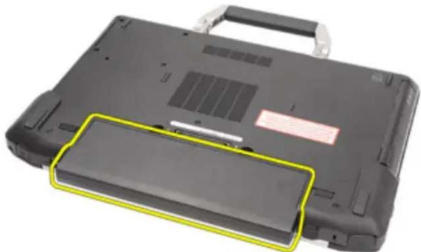
natural_image
Black laptop case with a yellow highlighted portion, showing front panel and cover (no text or symbols visible)Installing the Battery
- Slide the battery into its slot until it clicks into place.
- Follow the procedures in After working inside your computer.
Subscriber Identity Module (SIM) Card 7
Removing the Subscriber Identity Module (SIM) Card
- Follow the procedures in Before Working On Your Computer.
- Remove the Battery.
- Insert the SIM card into the slot.
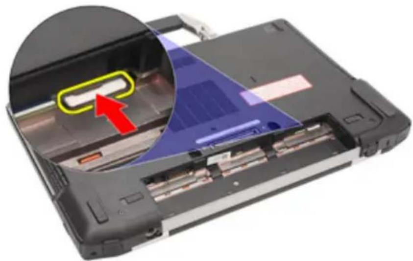
natural_image
Close-up of a computer monitor showing internal components and a highlighted drive mechanism (no text or symbols visible)- Remove the SIM card from the system.
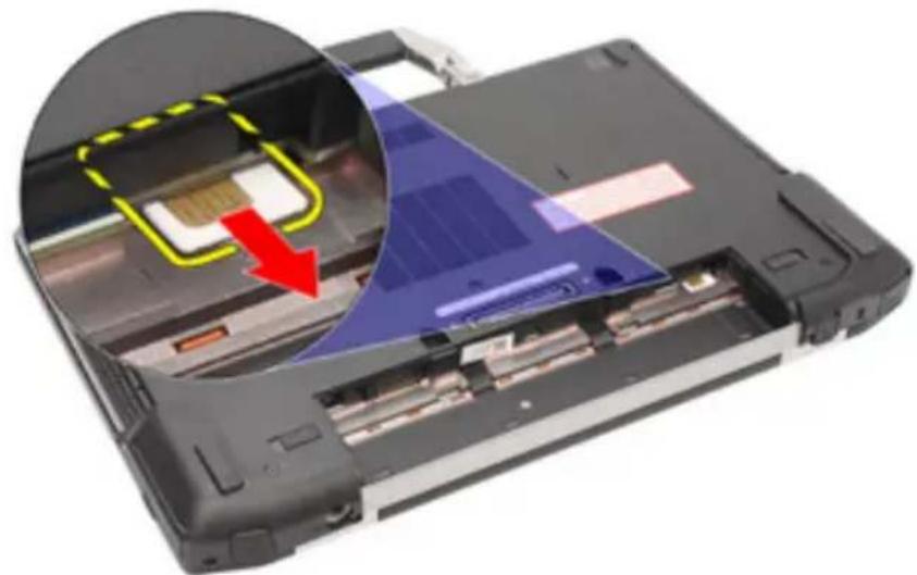
natural_image
Close-up of a laptop's internal components with a magnified inset showing a highlighted device (no text or symbols visible)Installing the Subscriber Identity Module (SIM) Card
- Slide the SIM card into its slot.
- Install the Battery.
- Follow the procedures in After Working Inside Your Computer.
Secure Digital (SD) Card 8
Removing the Secure Digital (SD) Card
- Follow the procedures in Before Working On Your Computer.
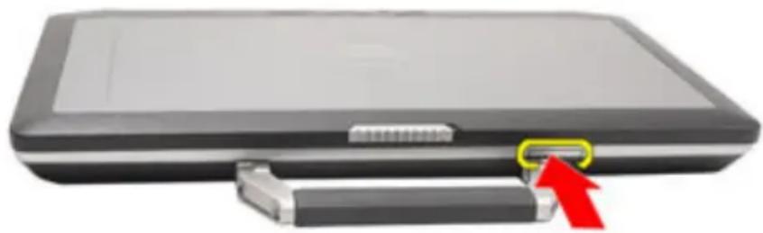
- Press in on the SD card to release the SD card from the computer.
natural_image
Black briefcase with USB port and red arrow pointing to a connector (no text or symbols visible)- Slide the SD card out of the computer.

natural_image
Black briefcase with a red arrow pointing to its side panel (no text or symbols visible)Installing the Secure Digital (SD) Card
- Slide the Secure Digital (SD) card into its slot until it clicks into place.
- Follow the procedures in After working inside your computer.
Base Cover 9
Removing the Base Cover
- Follow the procedures in Before Working On Your Computer.
- Remove the ATG Handle (only for E6420 ATG systems).
- Remove the ATG Port Cover (only for E6420 ATG systems).
- Remove the Battery.
- Remove the SD Card.
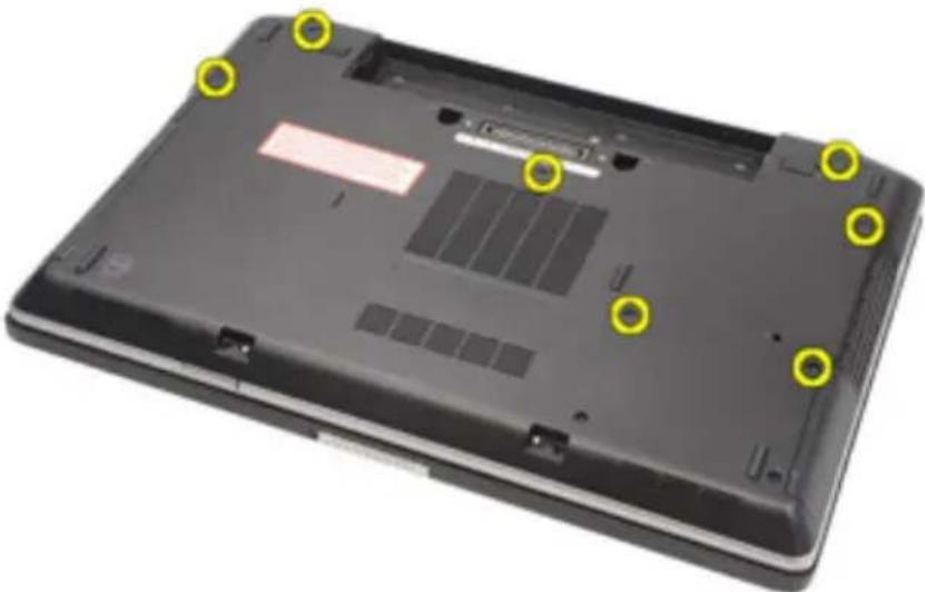
- Remove the screws that secure the base cover to the computer.
natural_image
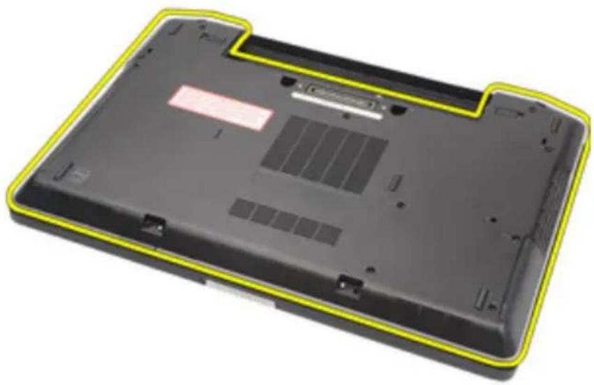
Laptop back with yellow circular annotations pointing to internal components (no text or symbols visible)- Lift the base cover up and away from the computer.
natural_image
Laptop back panel with yellow outline highlighting the front portion (no text or symbols visible)Installing the Base Cover
- Place the base cover to align the screw holes correctly with the computer.
- Tighten the screws that secure the base cover to the computer.
- Install the Secure Digital (SD) Card.
- Install the Battery.
- Install the ATG Port Cover(only for E6420 ATG systems).
- Install the ATG Handle(only for E6420 ATG systems).
- Follow the procedures in After Working Inside Your Computer.
Hard Drive 10
Removing the Hard Drive
- Follow the procedures in Before Working On Your Computer.
- Remove the Battery.
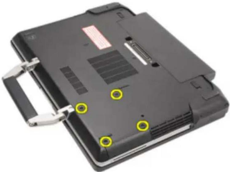
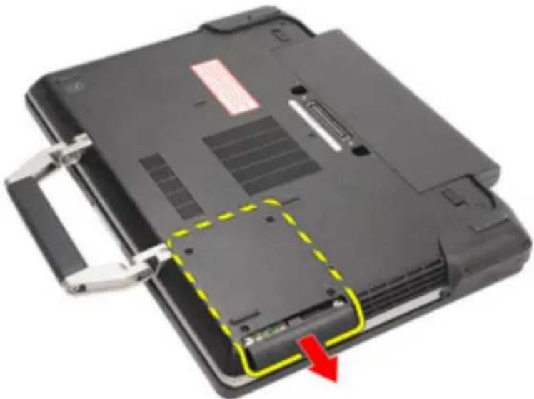
- Remove the screws that secure the hard drive to the computer.
natural_image
Laptop back panel with yellow circular annotations indicating mounting points (no text or symbols visible)- Slide and remove the hard drive out of the computer.
natural_image
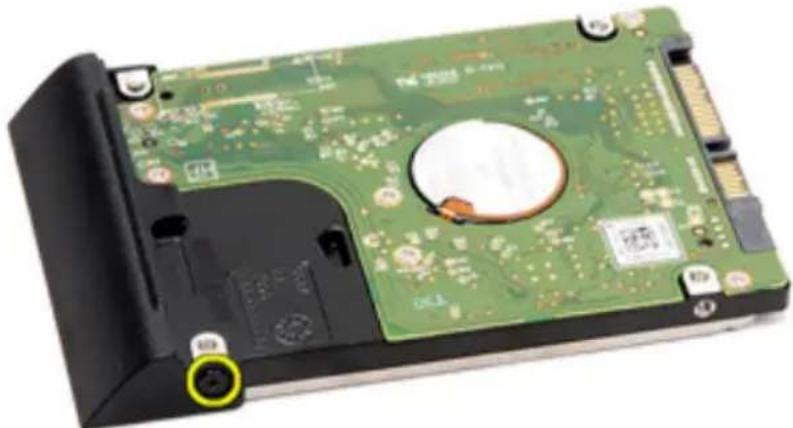
Laptop case with visible internal components and a yellow dashed outline indicating a highlighted portion, no text or symbols present.- Remove the screw that secures the hard drive caddy to the hard drive.
natural_image
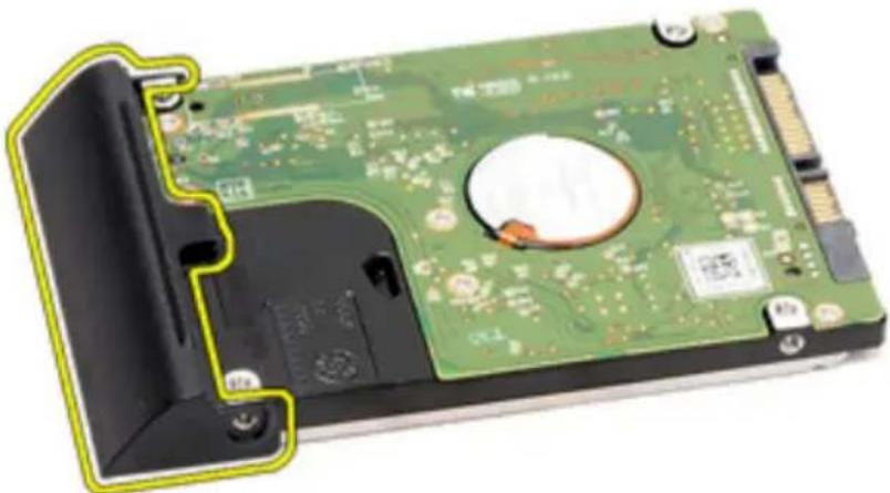
Close-up of a green hard disk drive head with visible circuit board and mounting holes (no text or symbols)- Pull and remove the hard drive caddy away from the hard drive.
natural_image
Close-up of a green hard disk drive head with visible internal circuitry and mounting holes (no text or symbols)Installing the Hard Drive
- Attach the hard drive caddy to the hard drive.
- Tighten the screw to secure the hard-drive caddy to the hard drive.
- Slide the hard drive into the computer.
- Replace and tighten the screws that secure the hard drive to the computer.
- Install the Battery.
- Follow the procedures in After working inside your computer.
Optical Drive 11
Removing The Optical Drive
- Follow the procedures in Before Working On Your Computer.
- Remove the Battery.
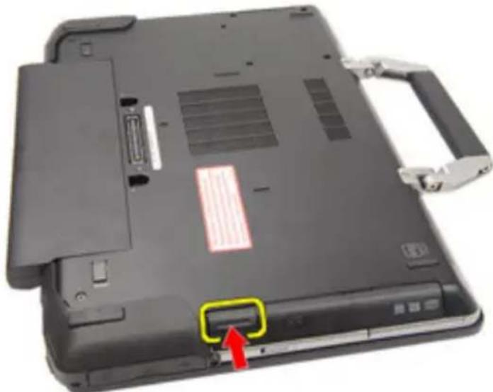
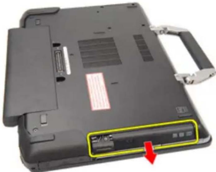
- Push in the drive latch into the slot.
natural_image
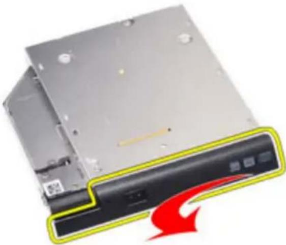
Laptop back panel with a highlighted drive button and red arrow indicator (no text or symbols)- Pull the optical drive using the drive latch.
natural_image
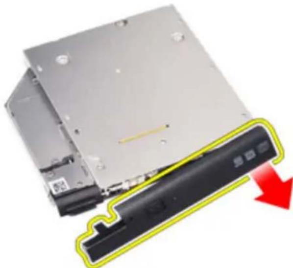
Laptop back panel with a highlighted internal component and a red arrow pointing to it (no visible text or symbols)- Pull the optical drive door from one side to release it.
natural_image
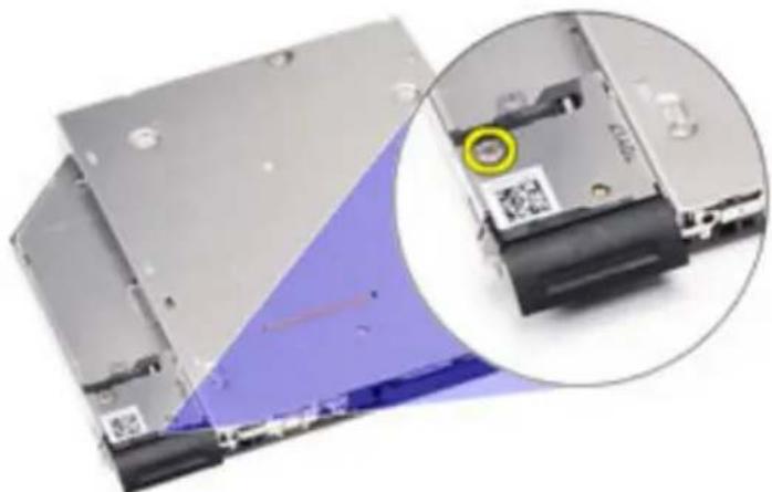
Exterior view of a computer drive chassis with a red arrow indicating compression (no text or symbols)- Pull the other side of the optical drive door to release it completely from the optical drive.
natural_image
Two electronic devices with a black battery partially removed, showing a red downward arrow (no text or symbols visible)- Remove the screw that secures the drive latch to the optical drive.
natural_image
Close-up of a computer drive showing internal components and a magnified view of the drive's internal structure (no text or symbols visible)- Remove the drive latch from the optical drive.
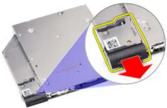
natural_image
Close-up of a computer hard drive showing internal components and a magnified view of the drive's internal structure (no text or symbols visible)- Remove the screws that secures the drive latch bracket to the optical drive.
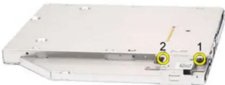
natural_image
Exterior view of a white electronic device casing with two labeled components (1 and 2) and a yellow circular highlight on the side panel.- Remove the drive latch bracket from the optical drive.
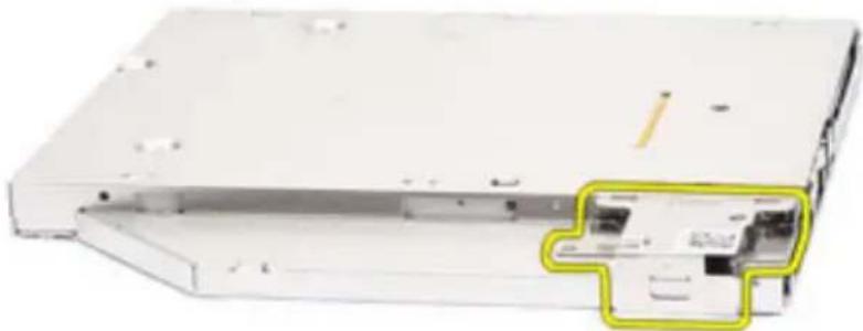
natural_image
White electronic device with a yellow highlighted internal component (no visible text or symbols)Installing the Optical Drive
- Insert the drive latch bracket into the optical drive.
- Tighten the screws that secure the drive latch bracket to the optical drive.
- Insert the drive latch into the optical drive.
- Tighten the screw that secures the drive latch to the optical drive.
- Push one side of the optical drive door to insert it completely into the optical drive.
- Pull the optical drive door from one side to insert it from the side.
- Insert the optical drive using the drive latch.
- Place the drive latch into the slot.
- Install the Battery.
- Follow the procedures in After working inside your computer.
Memory Card 12
Removing the Memory Card
- Follow the procedures in Before Working On Your Computer
- Remove the ATG Handle (only for E6420 ATG systems).
- Remove the ATG Port Cover (only for E6420 ATG systems).
- Remove the battery.
- Remove the Secure Digital (SD) card.
- Remove the base cover.
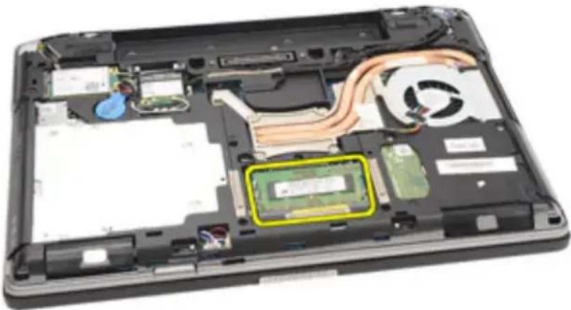
- Use your fingertips to spread apart the securing clips on each end of the memory module connector until the memory module pops up.
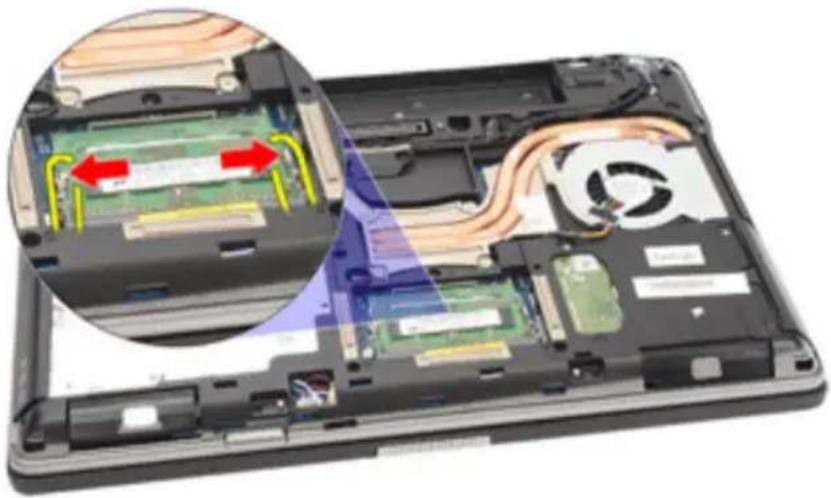
natural_image
Laptop interior showing internal circuit board and fan assembly with highlighted components (no text or symbols visible)- Remove the memory module from its connector on the system board by drawing the module from the system board at a 45-degree angle.
natural_image
Laptop interior showing internal circuit board and memory drive (no text or symbols visible)Installing the Memory Card
- Push the memory module into the memory slot.
- Press the clips to secure the memory module to the system board.
- Install the Base Cover.
- Install the Secure Digital (SD) card.
- Install the Battery.
- Install the ATG Port Cover(only for E6420 ATG systems).
- Install the ATG Handle(only for E6420 ATG systems).
- Follow the procedures in After Working Inside Your Computer.
Wireless Local Area Network (WLAN) Card 13
Removing the Wireless Local Area Network (WLAN) Card
- Follow the procedures in Before Working On Your Computer.
- Remove the ATG Handle (only for E6420 ATG systems).
- Remove the ATG Port Cover (only for E6420 ATG systems).
- Remove the battery.
- Remove the Secure Digital (SD) card.
- Remove the base cover.
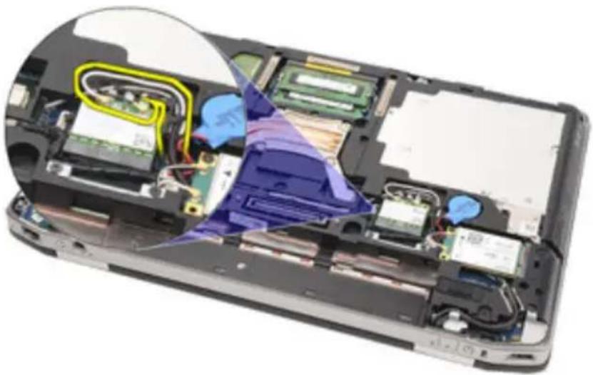
- Disconnect the antenna cables from the WLAN card.
natural_image
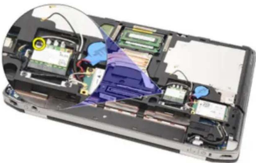
Interior view of a smartphone showing internal components and wiring (no text or symbols visible)- Remove the screw that secures the WLAN card to the computer.
natural_image
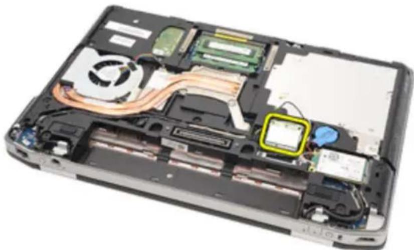
Interior view of a smartphone showing internal components and wiring (no visible text or symbols)- Slide and remove the WLAN card out from its slot on the system board.
natural_image
Interior view of a laptop showing internal components like CPU, RAM, and ventilation ducts (no text or symbols visible)Installing the Wireless Local Area Network (WLAN) Card
- Insert the WLAN card into its connector at a 45-degree angle.
- Replace and tighten the screw that secures the WLAN card to the computer.
- Connect the antenna cables to their respective connectors marked on the WLAN card.
- Install the ATG Port Cover(only for E6420 ATG systems).
- Install the ATG Handle(only for E6420 ATG systems).
- Install the base cover.
- Install the Secure Digital (SD) card.
- Install the battery
- Follow the procedures in After Working Inside Your Computer.
Wireless Wide Area Network (WWAN) Card 14
Removing the Wireless Wide Area Network (WWAN) Card
- Follow the procedures in Before Working On Your Computer.
- Remove the ATG Handle (only for E6420 ATG systems).
- Remove the ATG Port Cover (only for E6420 ATG systems).
- Remove the Battery.
- Remove the SD Card.
- Remove the Base Cover.
- Disconnect the antenna cables from the WWAN card.
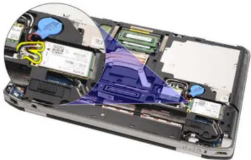
natural_image
Interior view of a smartphone showing internal components and battery pack (no text or symbols visible)- Remove the screw that secures the WWAN card to the computer.
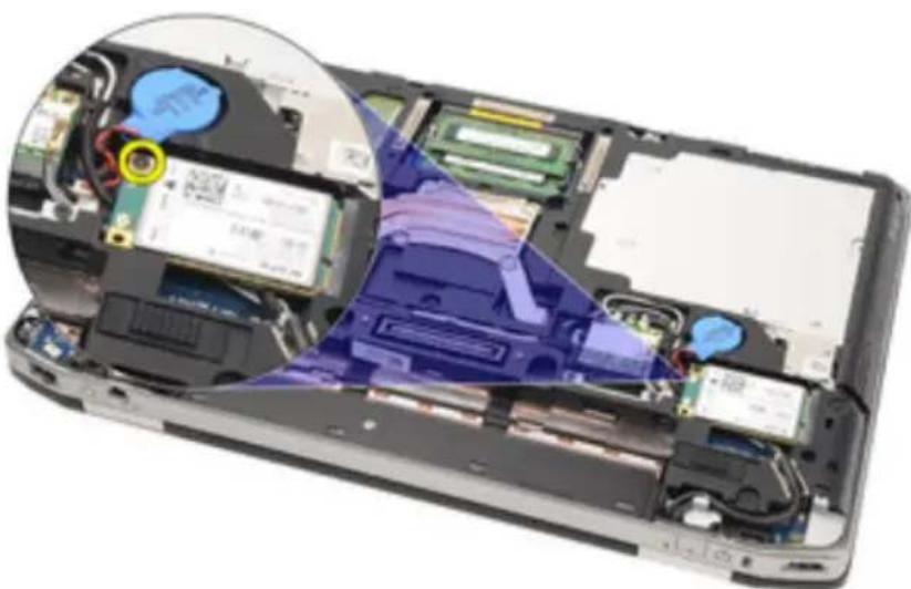
natural_image
Interior view of a smartphone showing internal components and a magnified view of the battery pack (no text or symbols visible)- Slide the WWAN card from its connector and remove it from the computer.
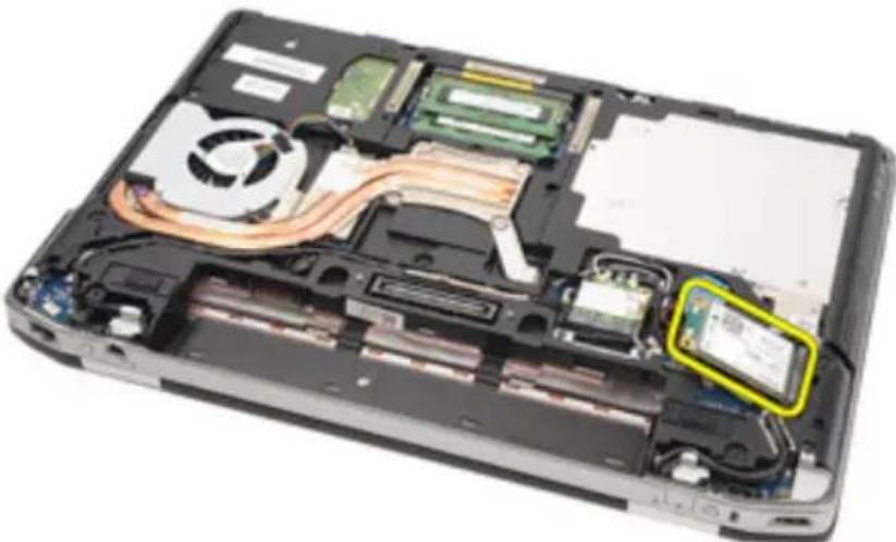
natural_image
Interior view of a laptop case showing internal components like CPU, RAM, and memory drive (no text or symbols visible)Installing the Wireless Wide Area Network (WWAN) Card
- Insert the WWAN card into its connector at a 45-degree angle.
- Replace and tighten the screw that secures the WWAN card to the computer.
- Connect the antenna cables to their respective connectors marked on the WWAN card.
- Install the Base Cover.
- Install the Secure Digital (SD) Card.
- Install the Battery.
- Install the ATG Port Cover(only for E6420 ATG systems).
- Install the ATG Handle(only for E6420 ATG systems).
- Follow the procedures in After Working Inside Your Computer.
Coin-Cell Battery 15
Removing the Coin-Cell Battery
- Follow the procedures in Before Working on Your Computer.
- Remove the ATG Handle (only for E6420 ATG systems).
- Remove the ATG Port Cover (only for E6420 ATG systems).
- Remove the Battery.
- Remove the SD Card.
- Remove the Base Cover.
- Disconnect any antennas routed over the coin cell battery.
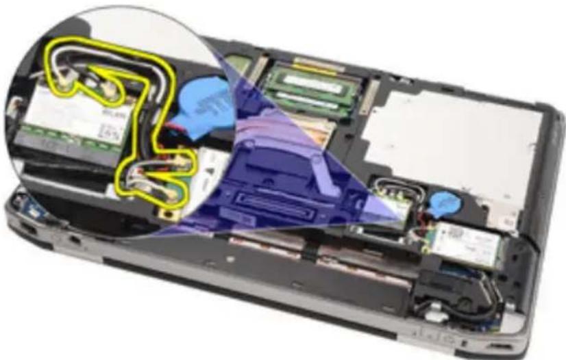
natural_image
Interior view of a smartphone showing internal components and wiring (no text or symbols visible)- Disconnect the coin-cell battery cable from the system board.
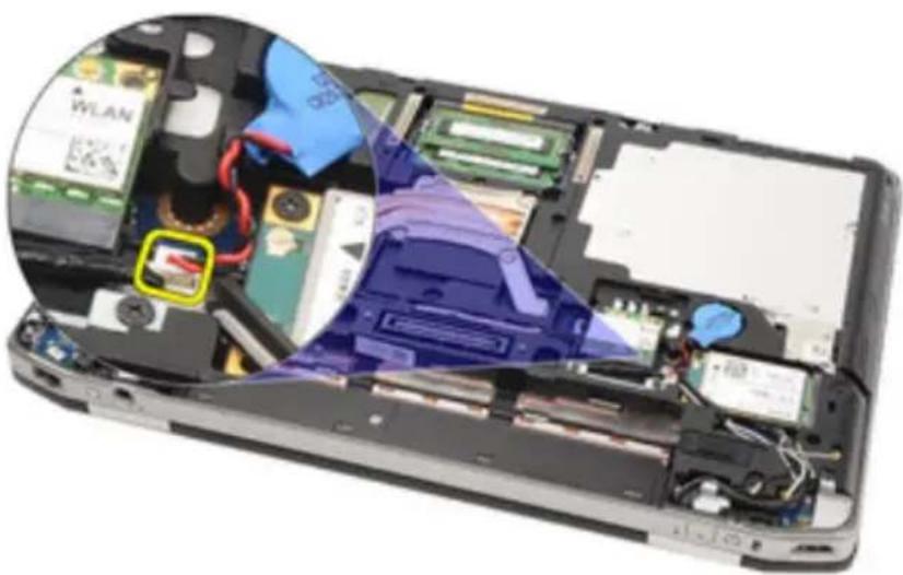
natural_image
Interior view of a smartphone showing internal components like circuit boards, RAM slots, and a device casing (no text or symbols visible)- Release and remove the coin-cell battery from the computer.
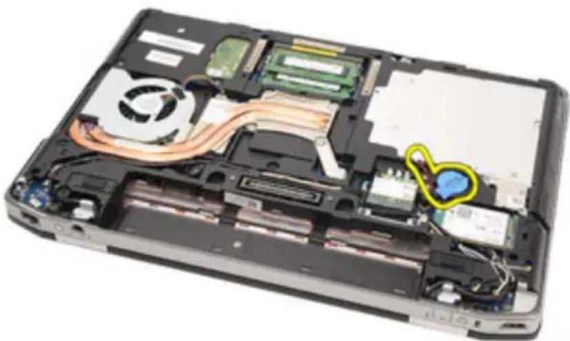
natural_image
Interior view of a computer case showing internal components like CPU, RAM, and a highlighted blue area (no text or symbols visible)Installing the Coin-Cell Battery
- Place the coin-cell battery in its location.
- Connect the coin-cell battery cable to the system board.
- Connect any antennas that were routed over the coin cell battery.
- Install the Base Cover.
- Install the Secure Digital (SD) card.
- Install the Battery.
- Install the ATG Port Cover(only for E6420 ATG systems).
- Install the ATG Handle(only for E6420 ATG systems).
- Follow the procedures in After Working Inside Your Computer.
Heat Sink 16
Removing The Heat Sink
- Follow the procedures in Before Working On Your Computer.
- Remove the ATG Handle (only for E6420 ATG systems).
- Remove the ATG Port Cover (only for E6420 ATG systems).
- Remove the Battery.
- Remove the SD Card.
- Remove the Base Cover.
- Disconnect the heat sink assembly cable.
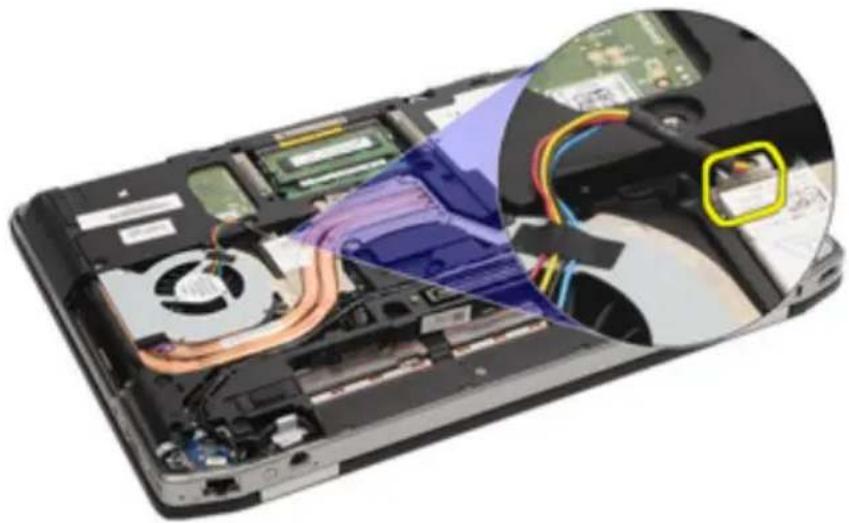
natural_image
Interior view of a computer with visible CPU socket, drive bays, and cable routing (no text or symbols)- Loosen the screws securing the heat sink.
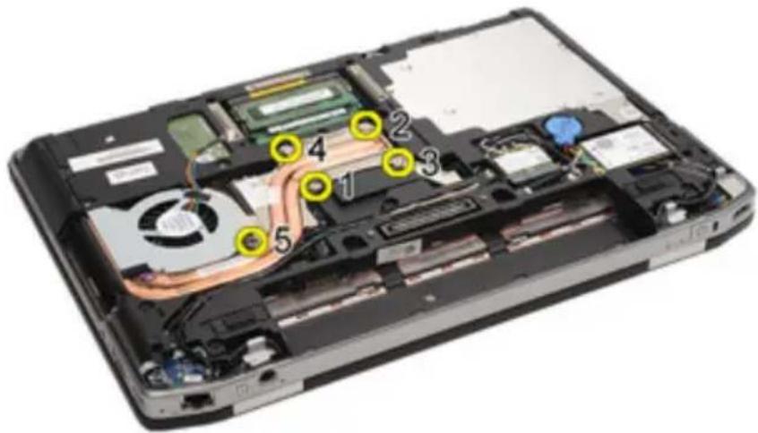
text_image
Laptop interior diagram with numbered annotations pointing to internal components like CPU, memory, and fan connections.- Remove the heat sink assembly from the system.
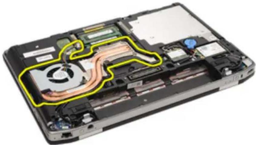
natural_image
Interior view of a laptop showing internal components like CPU, RAM slots, and heat exchanger (no text or symbols visible)- Rotate the processor cam lock in a counter-clockwise direction.
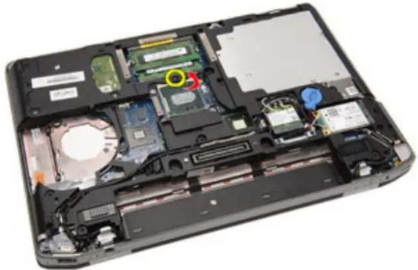
natural_image
Interior view of a laptop case showing internal components like CPU, memory, and drive slots (no text or symbols visible)- Remove the processor from the system.
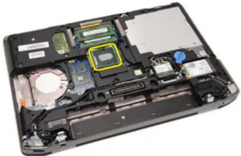
natural_image
Interior view of a laptop showing internal components like CPU socket and drive bays (no text or symbols visible)Installing The Heat Sink
- Insert the processor back into the system.
- Rotate the processor cam lock in a clockwise direction.
- Place the heat sink assembly into the system.
- Tighten the four screws securing the heat sink.
- Connect the heat sink assembly cable.
- Install the Base Cover.
- Install the Secure Digital (SD) Card.
- Install the Battery.
- Install the ATG Port Cover(only for E6420 ATG systems).
- Install the ATG Handle(only for E6420 ATG systems).
- Follow the procedures in After Working Inside Your Computer.
Bluetooth Card 17
Removing the Bluetooth Card
- Follow the procedures in Before Working On Your Computer.
- Remove the ATG Handle (only for E6420 ATG systems).
- Remove the ATG Port Cover (only for E6420 ATG systems).
- Remove the Battery.
- Remove the Secure Digital Card.
- Remove the Base Cover.
- Remove the Hard Drive.
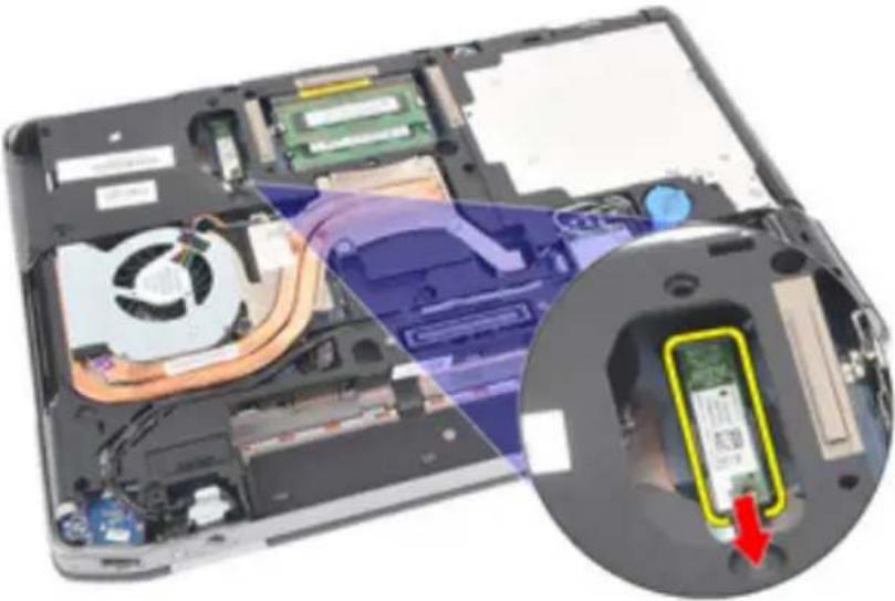
- Remove the screw that secures the bluetooth card to the computer
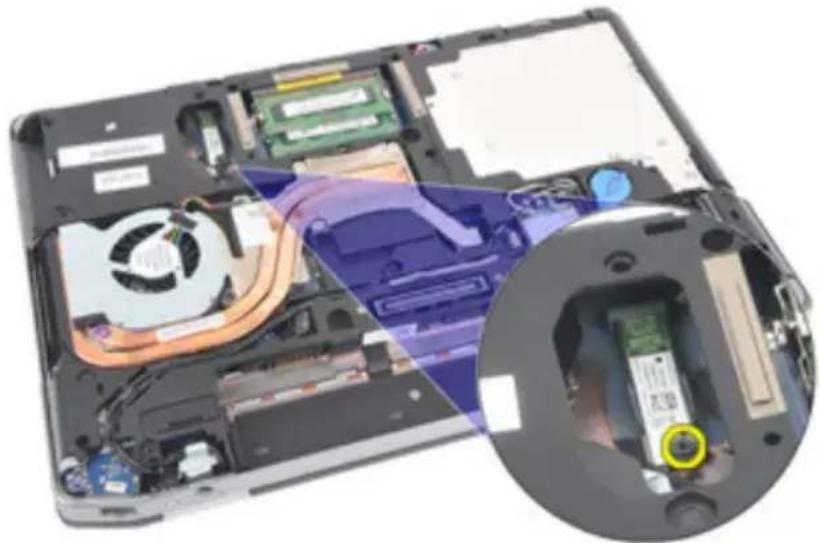
natural_image
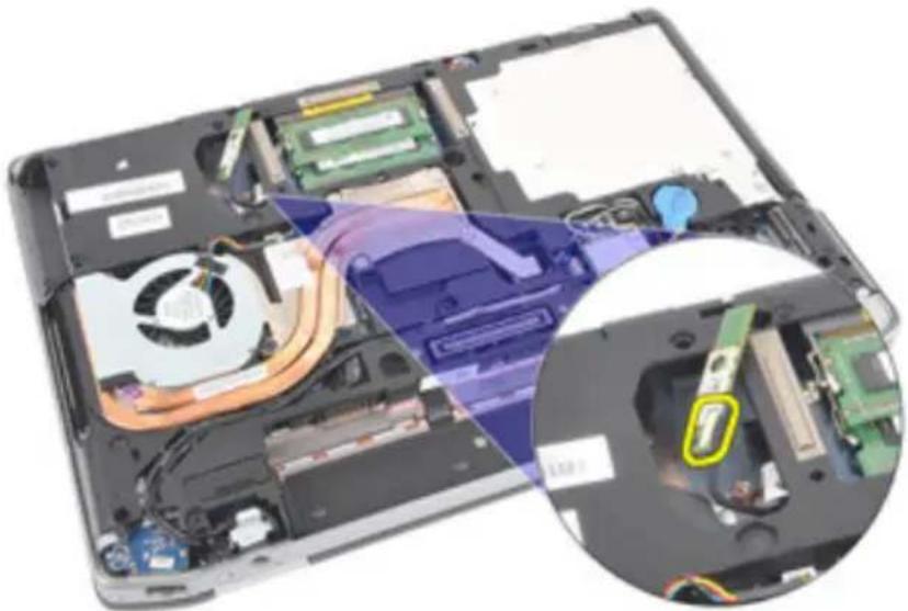
Interior view of a laptop showing internal components like CPU, RAM slots, and drive bays (no text or symbols visible)- Remove the bluetooth card from the holder.
natural_image
Laptop interior showing internal components including CPU, motherboard, and a highlighted drive module (no text or symbols visible)- Disconnect the bluetooth cable.
natural_image
Laptop interior showing internal components including CPU, fan, and drive slots (no text or symbols visible)Installing the Bluetooth Card
- Connect the bluetooth cable to the bluetooth card.
- Replace and tighten the screw to secure the bluetooth card to the computer.
- Install the Hard Drive.
- Install the Base Cover.
- Install the SD Card.
- Install the Battery.
- Install the ATG Port Cover(only for E6420 ATG systems).
- Install the ATG Handle(only for E6420 ATG systems).
- Follow the procedures in After Working Inside Your Computer.
Keyboard Trim 18
Removing the Keyboard Trim
- Follow the procedures in Before Working On Your Computer.
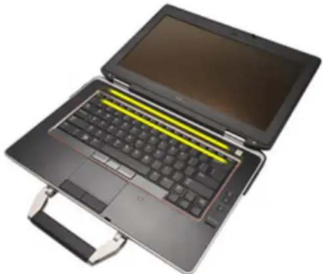
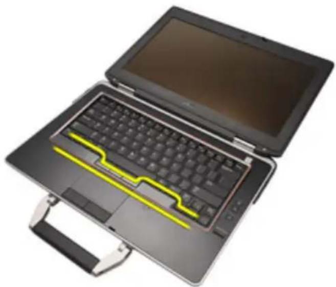
- Using a plastic scribe, pry the keyboard trim from the top edge to release it from the computer.
natural_image
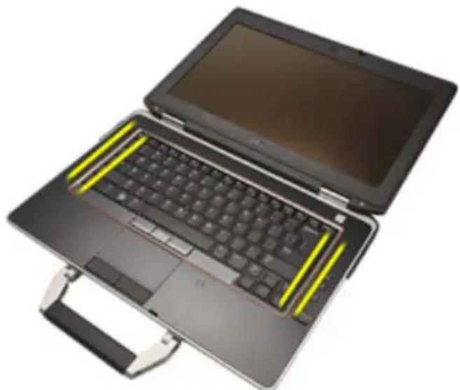
Laptop with keyboard and front panel, partially open to show front view (no visible text or symbols)- Pry along the sides.
natural_image
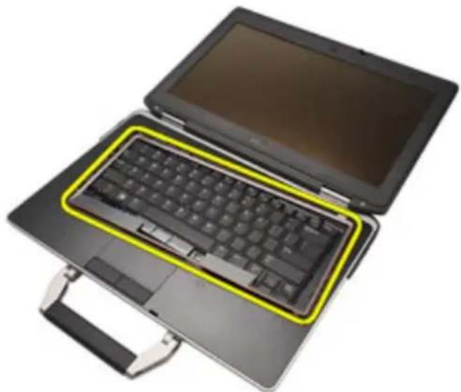
Top-down view of a black laptop with yellow keyboard shortcuts, resting on a stand (no text or symbols visible)- Release the tabs part of the trim.
natural_image
Laptop with open case and yellow circuit board on front (no visible text or symbols)- Gently lift the keyboard trim to release it from the computer.
natural_image
Laptop with a highlighted keyboard placed on top, showing front and side views (no text or symbols visible)Installing the Keyboard Trim
- Align the keyboard trim with the keyboard and gently snap it into place.
- Follow the procedures in After Working Inside Your Computer.
Keyboard 19
Removing the Keyboard
- Follow the procedures in Before Working On Your Computer.
- Remove the Battery.
- Remove the Keyboard Trim.
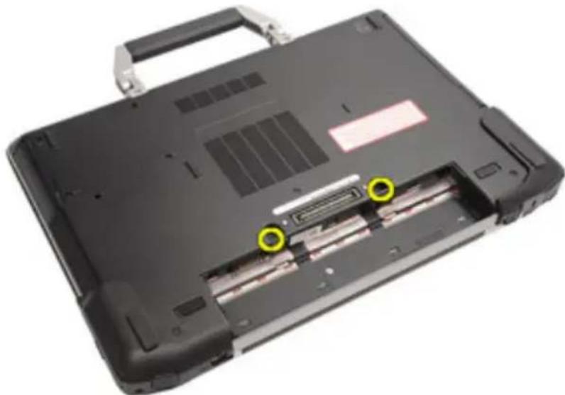
- Remove the screws that secure the keyboard at the bottom of the computer.
natural_image
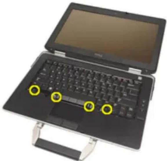
Laptop case with visible internal components and two yellow circular annotations (no text or symbols)- Remove the screws that secure the keyboard on the system.
natural_image
Laptop keyboard with open lid and handle, showing three yellow circular annotations on keys (no text or symbols visible)- Carefully flip the keyboard over and lay it toward the display.
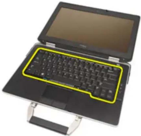
natural_image
Laptop with a highlighted keyboard and open lid, no visible text or symbols- Disconnect the keyboard cable from the system board.
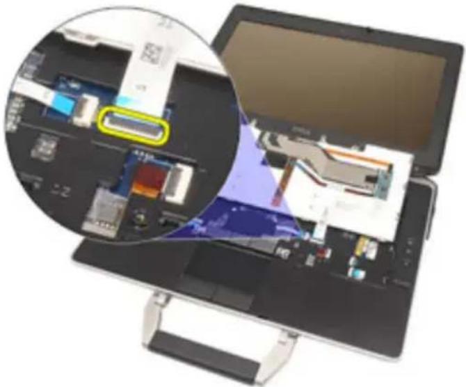
natural_image
Laptop displaying a 3D printer with internal circuitry and a magnified inset showing the printer's internal components (no visible text or symbols)- Remove the keyboard from the computer.
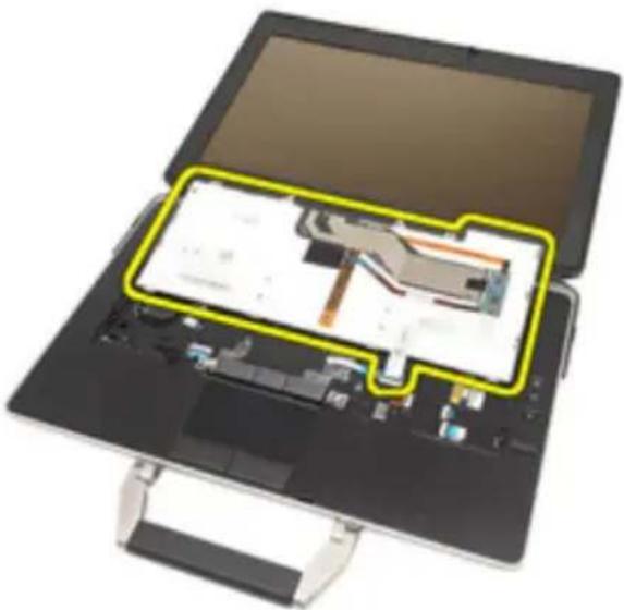
natural_image
Top-down view of a tablet device with an open screen showing internal circuitry and a highlighted green section (no text or symbols visible)- Remove the tape securing the keyboard cable from the keyboard.
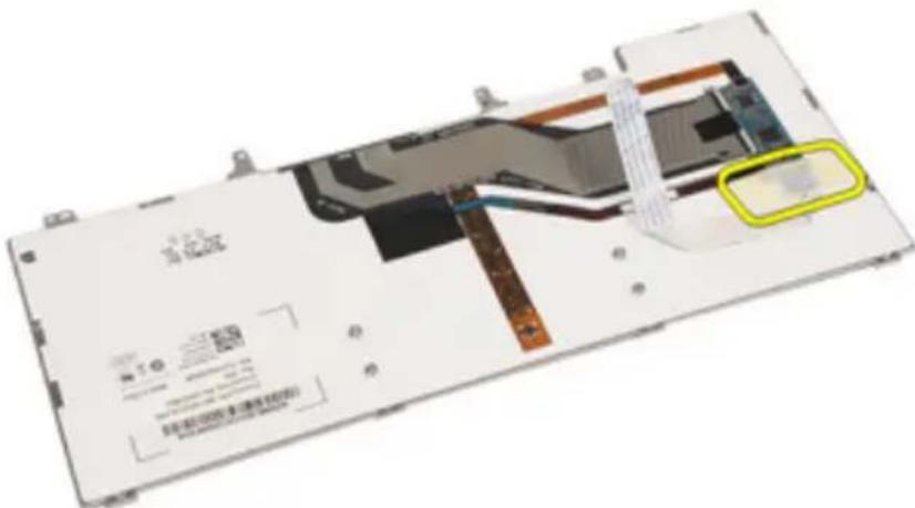
text_image
Technical diagram of a device with Chinese labels and internal components, highlighting a highlighted section.- Unlock the cable holder.
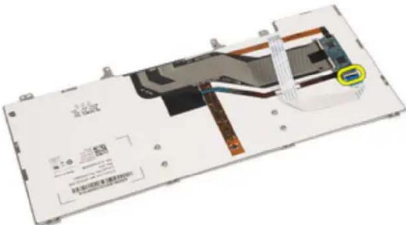
text_image
Technical diagram of a device with Chinese labels and annotations, showing internal components and a highlighted section with a blue arrow.- Disconnect and remove the keyboard cable from the keyboard.
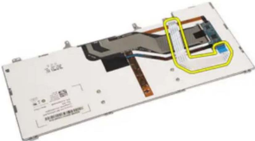
text_image
Diagram of a device's internal structure with Chinese labels and annotations, highlighting a highlighted section.Installing the Keyboard
- Connect the keyboard cable and secure it to the keyboard using the tape.
- Connect the keyboard cable to its connector on the system board.
- Replace and tighten the screws that secure the keyboard to the computer.
- Install the Battery.
- Install the Keyboard Trim
- Follow the procedures in After Working Inside Your Computer.
Modem Card 20
Removing the Modem Card
- Follow the procedures in Before Working On Your Computer.
- Remove the Battery.
- Remove the Keyboard Trim.
- Remove the Keyboard.
- Remove the screw securing the modem card to the computer.
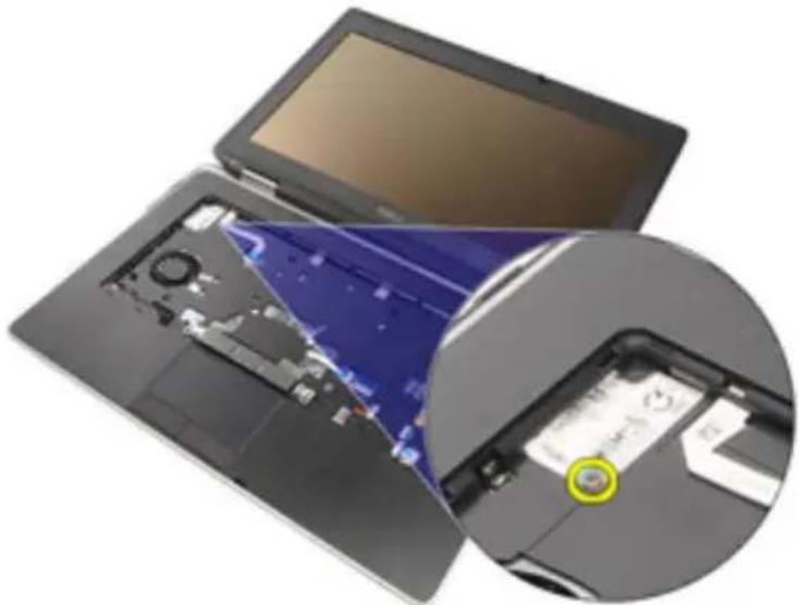
natural_image
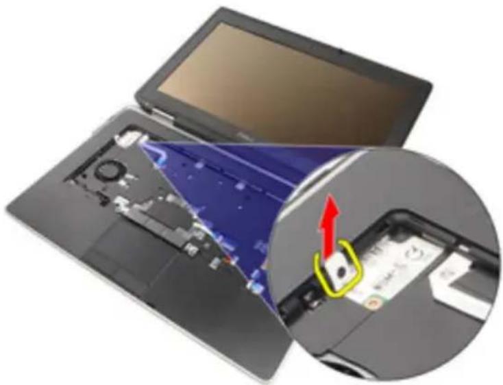
Laptop with open circuit board and close-up of internal components (no visible text or symbols)- Pull out the tab from underneath the palmrest.
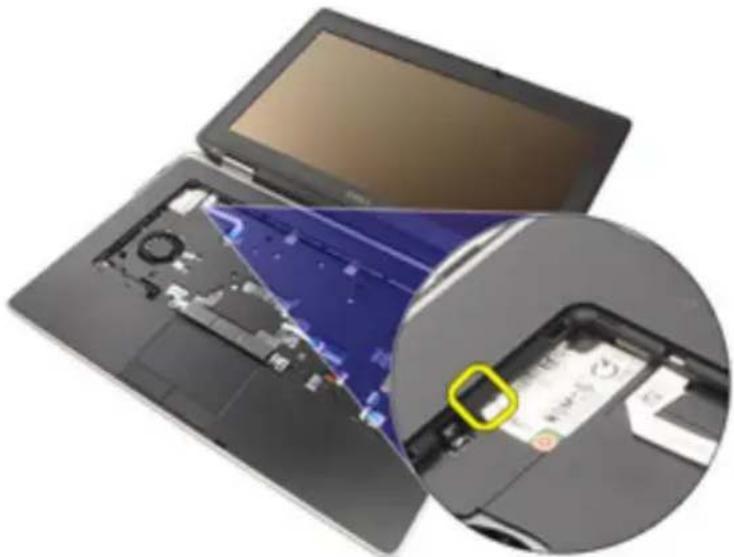
natural_image
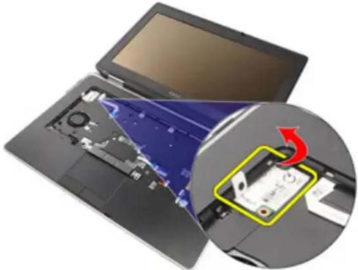
Laptop with open circuit board and close-up of a smartwatch showing a screen (no text or symbols visible)- Lift the tab to disconnect the holder.
natural_image
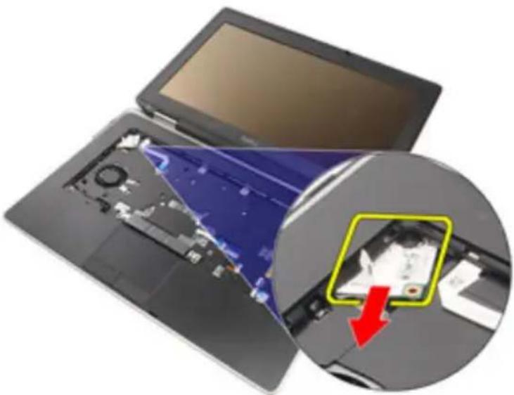
Laptop interior showing internal circuit board and a close-up of the device's screen (no visible text or symbols)- Rotate the modem card at an angle.
natural_image
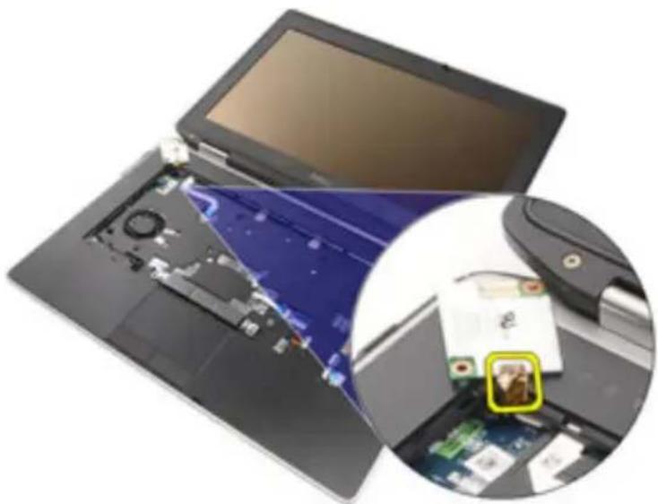
Laptop with internal circuit board and a magnified view showing a device's internal structure (no text or symbols visible)- Remove modem card from the slot away from the computer.
natural_image
Laptop with open circuit board and highlighted internal components, showing a red arrow indicating a detail (no text or symbols present)- Disconnect the modem cable from the modem card and remove it from the system.
natural_image
Laptop with open circuit board and close-up of internal components (no visible text or symbols)Installing the Modem Card
- Connect the modem cable to the modem card on the system board.
- Place the modem card in its slot in the computer.
-
Tighten the screw securing the modem card to the system.
-
Install the Keyboard Trim.
-
Install the Keyboard.
-
Install the Battery.
-
Follow the procedures in After working inside your computer.
Palm Rest 21
Removing the Palm Rest Assembly
- Follow the procedures in Before Working On Your Computer.
- Remove the ATG Handle (only for E6420 ATG systems).
- Remove the ATG Port Cover (only for E6420 ATG systems).
- Remove the Battery.
- Remove the SD Card.
- Remove the Base Cover.
- Remove the Optical Drive.
- Remove the Hard Drive.
- Remove the WWAN Card.
- Remove the Bluetooth Card.
- Remove the Keyboard Trim.
- Remove the Keyboard.
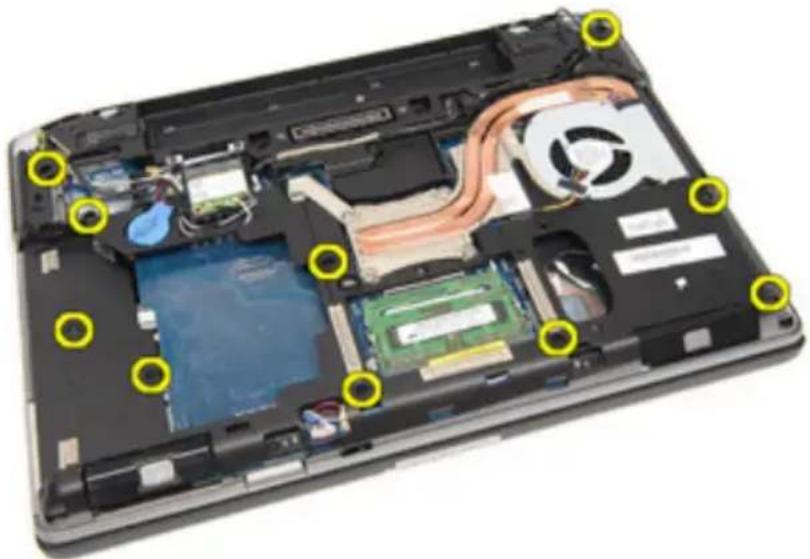
- Remove the screws that secure the palm rest assembly to the computer.
natural_image
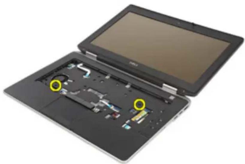
Laptop interior showing exposed circuit board, CPU socket, and heat sink with yellow circular annotations (no text or symbols)- Turn the system and remove the screws that secure the palm rest assembly to the computer.
natural_image
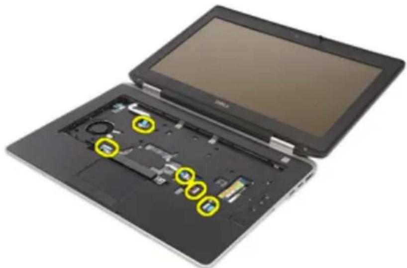
Open tablet device with visible internal components and two yellow arrows indicating features (no text or symbols)- Release and disconnect the LED, smart card, touchpad, RFID, and ExpressCard cable from the system board.
natural_image
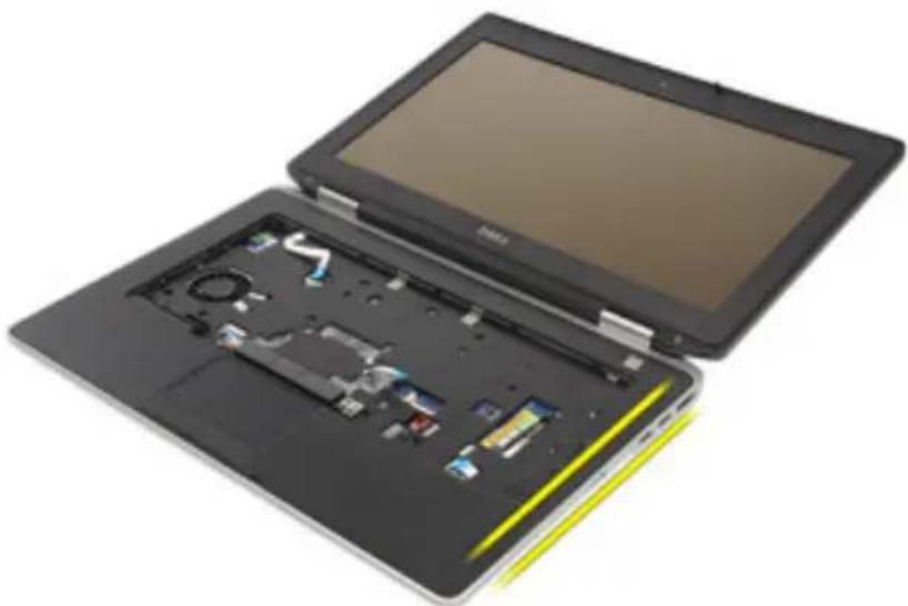
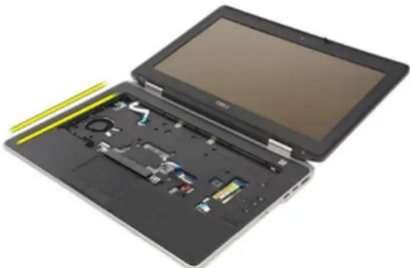
Two open laptops with visible internal components and yellow circular annotations (no text or symbols)- Using a plastic scribe, gently pry out the top right corner of the palm rest and run along the scribe to the right side of the palm rest to release the snaps.
natural_image
Open laptop with exposed internal components, showing battery, circuit board, and drive slots (no text or symbols visible)- Continue to use the scribe to run along the top and left side of the palm rest until all snaps are released.
natural_image
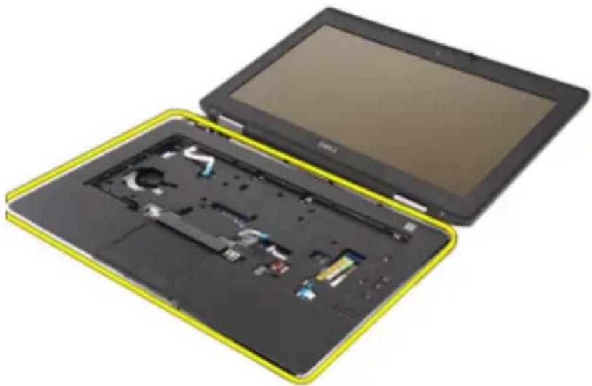
Open laptop with exposed internal circuitry and a yellow cable inserted (no text or symbols visible)- Lift the top side at a 25-degree angle, pull the palm rest towards the screen, and remove it from the computer.
natural_image
Two open digital tablets with visible internal components, one black and one yellow, showing internal wiring (no text or symbols)Installing the Palm Rest Assembly
- Align the palm rest assembly with the computer and gently snap it into place.
- Replace and tighten the screws that secure the palm rest assembly to the system board.
- Connect the LED, smart card, touchpad, RFID, and ExpressCard cables to the system board.
-
Replace and tighten the screws that secure the palm rest assembly to the computer.
-
Install the Keyboard.
- Install the Keyboard Trim.
- Install the Bluetooth Card.
- Install the WWAN Card.
-
Install the Hard Drive.
-
Install the Optical Drive.
-
Install the Base Cover.
-
Install the Secure Digital (SD) Card.
-
Install the Battery.
-
Install the ATG Port Cover(only for E6420 ATG systems).
-
Install the ATG Handle(only for E6420 ATG systems).
-
Follow the procedures in After Working Inside Your Computer
Smart Card Reader 22
Removing the Smart Card
- Follow the procedures in Before Working On Your Computer.
- Remove the ATG Handle (only for E6420 ATG systems).
- Remove the ATG Port Cover (only for E6420 ATG systems).
- Remove the Battery.
- Remove the SD Card.
- Remove the Base Cover.
- Remove the Hard Drive.
- Remove the Keyboard Trim.
- Remove the Keyboard.
- Remove the Palmrest Assembly.
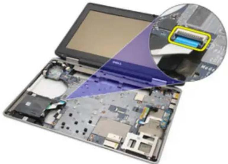
- Remove the Smart Card Reader cable from the system board.
natural_image
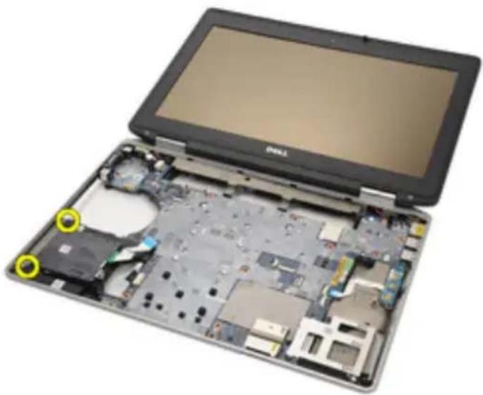
Laptop with open circuit board and close-up of internal components (no visible text or symbols)- Remove the screws securing the Smart Card Reader to the computer.
natural_image
Laptop with exposed internal circuit board and two yellow circular annotations highlighting specific components (no text or symbols visible)- Remove the Smart Card Reader from the computer.
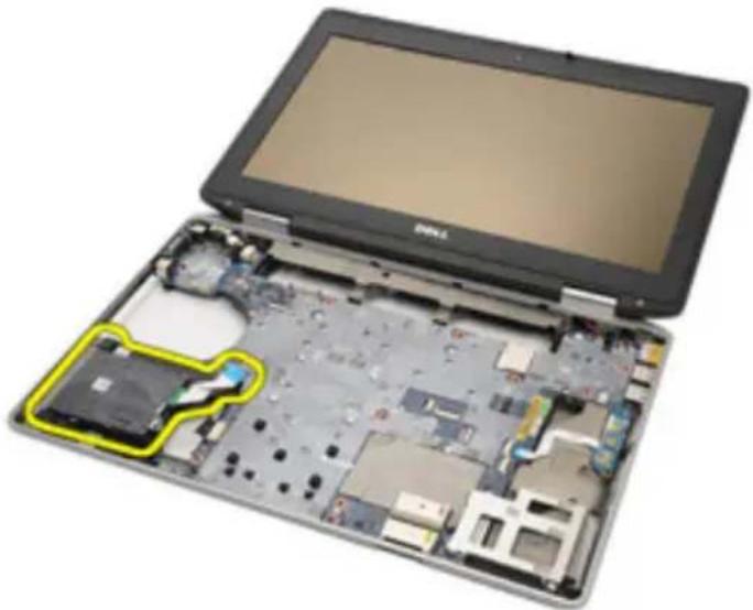
natural_image
Laptop with exposed internal circuit board and battery pack, highlighted by a yellow outline (no text or symbols visible)Installing the Smart Card
- Replace the Smart Card Reader in the computer in its original position.
- Tighten the screws of the Smart Card Reader.
- Connect the Smart Card Reader cable on the system board.
- Install the Palmrest Assembly.
- Install the Keyboard.
- Install the Keyboard Trim.
- Install the Hard Drive.
- Install the Base Cover.
- Install the SD Card.
- Install the Battery.
- Install the ATG Port Cover(only for E6420 ATG systems).
- Install the ATG Handle(only for E6420 ATG systems).
- Follow the procedures in After Working Inside Your Computer.
Media Board 23
Removing The Media Board
- Follow the procedures in Before Working On Your Computer.
- Remove the ATG Handle (only for E6420 ATG systems).
- Remove the ATG Port Cover (only for E6420 ATG systems).
- Remove the Battery.
- Remove the SD Card.
- Remove the Optical Drive.
- Remove the Base Cover.
- Remove the Hard Drive.
- Remove the WWAN Card.
- Remove the Bluetooth Card.
- Remove the Keyboard Trim.
- Remove the Keyboard.
- Remove the Palmrest Assembly.
- Disconnect the media board cable from the system board.
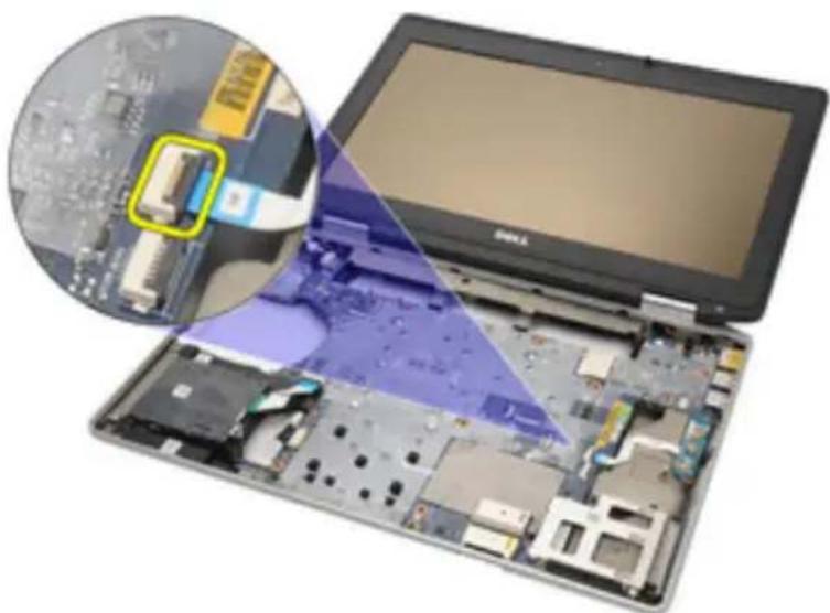
natural_image
Laptop with open circuit board and close-up of internal components (no visible text or symbols)- Remove the screws that secure the media board to the computer.
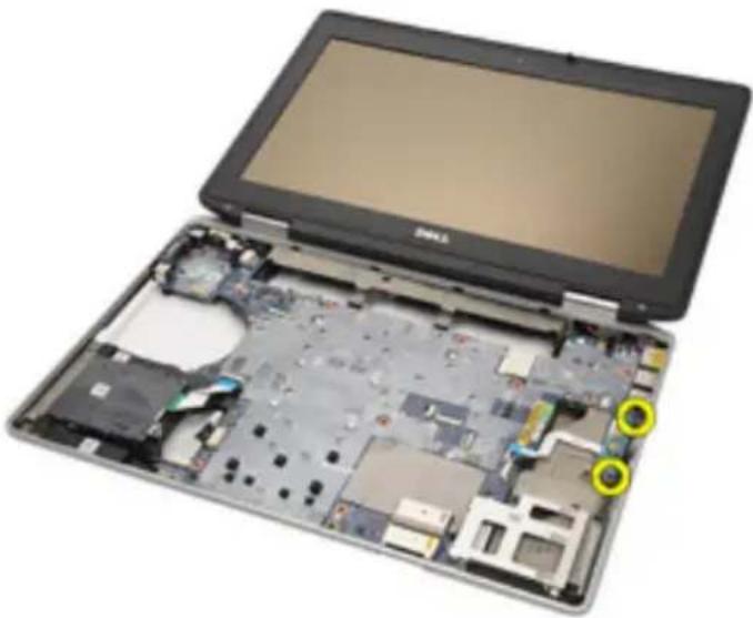
natural_image
Laptop with exposed internal circuit board and two yellow circular annotations highlighting specific components (no text or symbols visible)- Remove the media board from the computer.
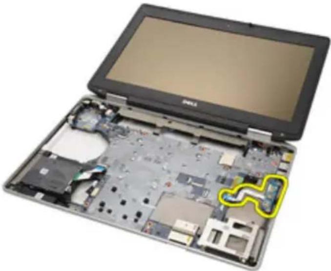
natural_image
Laptop with exposed internal circuit board and a yellow outline highlighting a component (no text or symbols visible)Installing the Media Board
- Align the media board to its original position on the computer.
- Replace and tighten the screws that secure the media board to the computer.
- Connect the media board cable to the system board.
- Install the ATG Handle (for E6420 ATG systems only).
- Install the ATG Port Cover (for E6420 ATG systems only).
- Install the Palmrest Assembly.
- Install the Keyboard.
- Install the Keyboard Trim.
- Install the WWAN Card.
- Install the Bluetooth Card.
- Install the Hard Drive.
- Install the Optical Drive.
- Install the Base Cover.
- Install the SD Card.
- Install the Battery.
- Install the ATG Port Cover(only for E6420 ATG systems).
- Install the ATG Handle(only for E6420 ATG systems).
- Follow the procedures in After Working Inside Your Computer.
ExpressCard Cage 24
Removing the ExpressCard Cage
- Follow the procedures in Before Working On Your Computer.
- Remove the ATG Handle (only for E6420 ATG systems).
- Remove the ATG Port Cover (only for E6420 ATG systems).
- Remove the Battery.
- Remove the SD Card.
- Remove the Base Cover.
- Remove the Optical Drive.
- Remove the Hard Drive.
- Remove the Bluetooth Card
- Remove the Keyboard Trim.
- Remove the Keyboard.
- Remove the Palmrest Assembly.
- Remove the screws securing the ExpressCard cage to the computer.
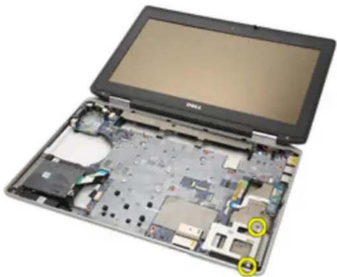
natural_image
Laptop with exposed internal circuit board and two yellow circular annotations highlighting specific components (no readable text or symbols)- Lift the ExpressCard slot to a 45-degree angle and remove the slot.
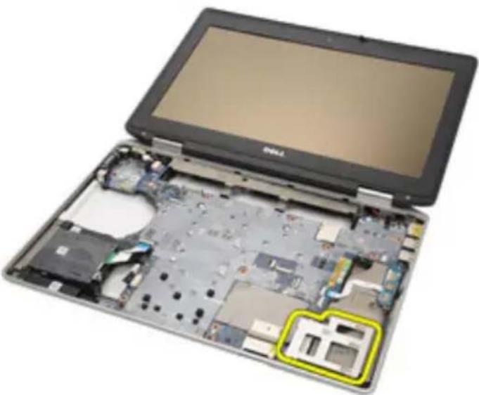
natural_image
Laptop with exposed internal circuit board and a highlighted component (no text or symbols visible)Installing the ExpressCard Cage
- Align the ExpressCard cage into its slot.
- Replace and tighten the screws securing the ExpressCard cage to the computer.
- Install the Palm rest Assembly.
- Install the Keyboard.
- Install the Keyboard Trim.
- Install the Bluetooth Card.
- Install the Hard Drive
- Install the Optical Drive.
- Install the Base Cover.
- Install the Secure Digital (SD) Card.
- Install the Battery.
- Install the ATG Port Cover(only for E6420 ATG systems).
- Install the ATG Handle(only for E6420 ATG systems).
- Follow the procedures in After working inside your computer.
System Board Components 25
Removing the System Board
- Follow the procedures in Before Working On Your Computer.
- Remove the ATG Handle (only for E6420 ATG systems).
- Remove the ATG Port Cover (only for E6420 ATG systems).
- Remove the Battery.
- Remove the Secure Digital Card.
- Remove the Base Cover.
- Remove the ExpressCard.
- Remove the Optical Drive.
- Remove the Memory.
- Remove the Hard Drive.
- Remove the WLAN Card.
- Remove the WWAN Card.
- Remove the Coin Cell Battery.
- Remove the Heat Sink and Processor.
- Remove the Bluetooth Card.
- Remove the Keyboard Trim.
- Remove the Keyboard.
- Remove the Modem Card
- Remove the Palmrest Assembly.
- Remove the ExpressCard Cage.
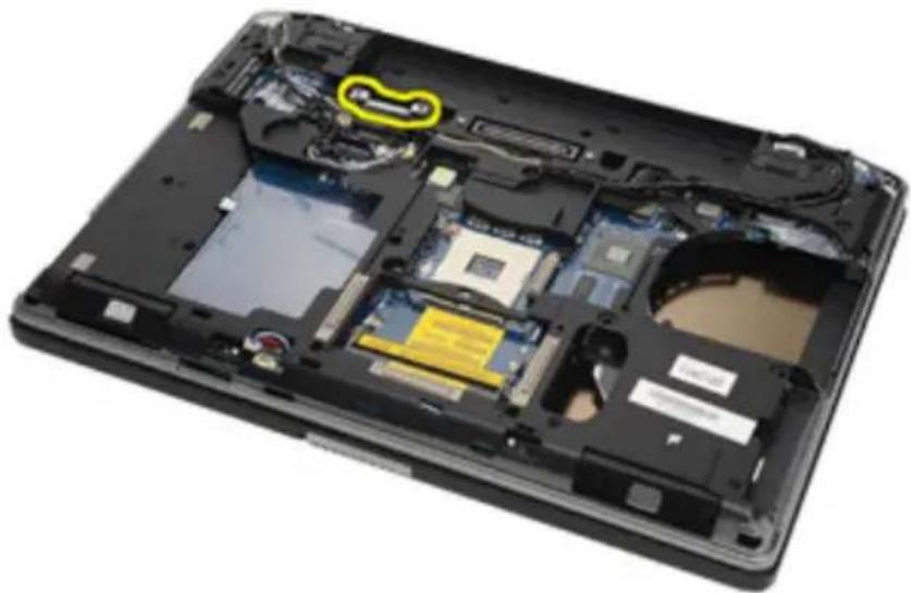
- Disconnect and release the speaker cables from the system board.
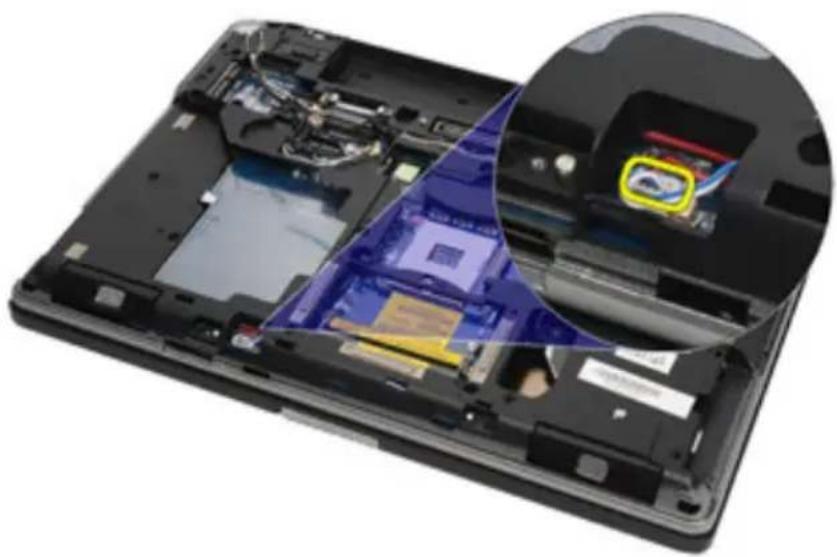
natural_image
Interior view of a laptop showing internal components and a close-up of the screen (no visible text or symbols)- Remove the screws from the video cable holder.
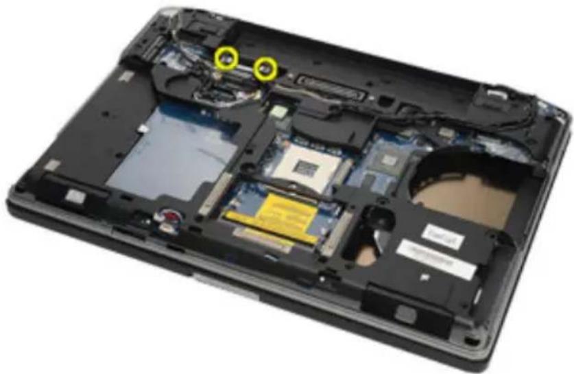
natural_image
Interior view of a laptop showing exposed circuit board and memory modules (no text or symbols visible)- Remove the video cable holder.
natural_image
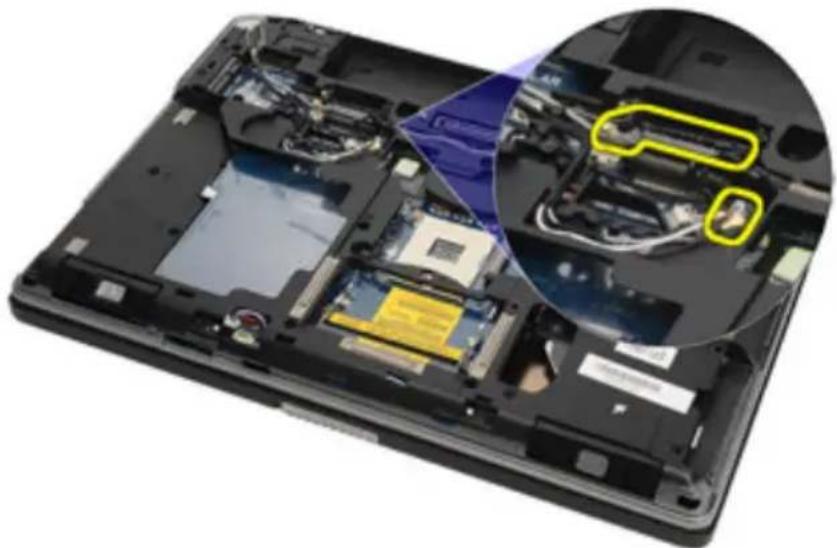
Laptop interior showing exposed circuit board and memory modules, with a highlighted yellow region (no text or symbols visible)- Disconnect the video camera and LED cables from the system board.
natural_image
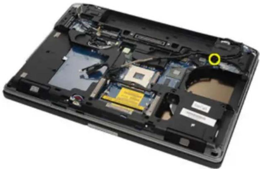
Interior view of a laptop showing internal components and a magnified view of the engine compartment (no text or symbols visible)- Remove the screw that secures the system board to the computer.
natural_image
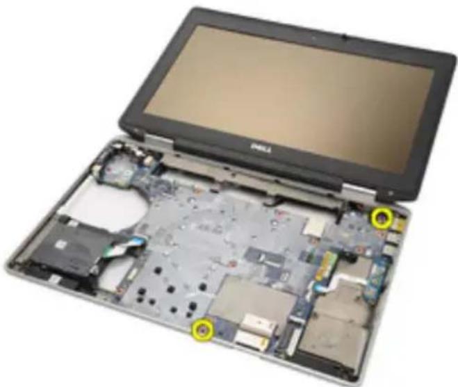
Laptop interior showing exposed circuit board and memory modules (no text or symbols visible)- Flip and remove the screws from the system board.
natural_image
Laptop with exposed internal circuit board and battery casing, showing no visible text or symbols- Remove the Smart Card reader cable, Media Board cable, and DC-in Cable.
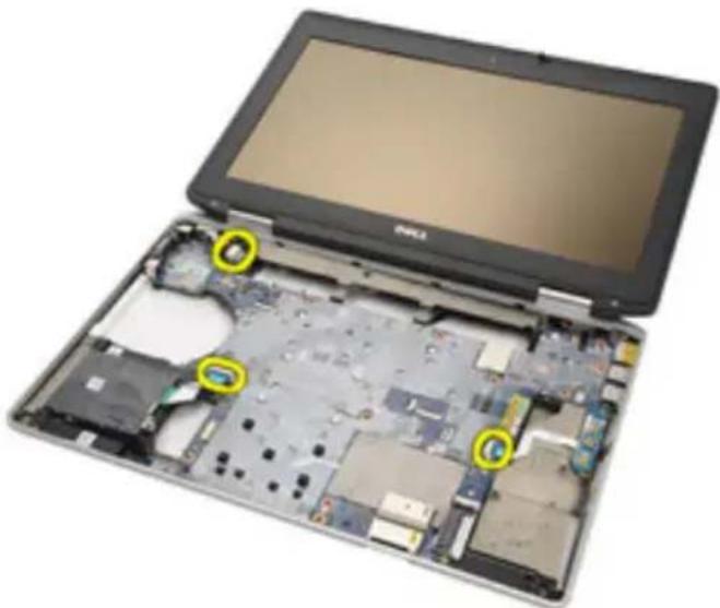
natural_image
Laptop with exposed internal circuit board and two yellow circular annotations highlighting specific components (no text or symbols visible)- Disconnect the motherboard from the IO Board.
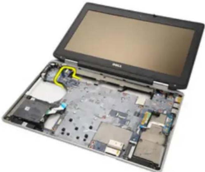
natural_image
Laptop with exposed internal circuit board and a highlighted yellow area (no text or symbols visible)- Slide to unlock system board from the port connectors.
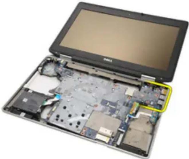
natural_image
Laptop with exposed internal circuit board and battery pack, highlighted by a yellow highlight (no text or symbols visible)- Remove the system board.
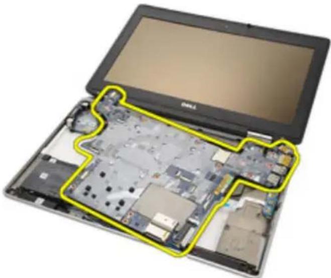
natural_image
Laptop with exposed internal circuit board and a yellow outline highlighting the component (no text or symbols visible)Installing the System Board
- Align the system board into its original position on the computer.
- Connect the system board to the I/O board.
- Connect the Smart Card reader cable, Media Board cable, and DC-in Cable to the system board.
- Replace and tighten the screws that secure the system board to the computer.
- Route and connect the video camera and LED cables to the system board.
-
Place the video cable holder and tighten the screws securing the video cable holder to the system board.
-
Connect the speaker cable to the system board.
-
Install the ExpressCard Cage
- Install the Palmrest Assembly.
- Install the Modem Card.
- Install the Keyboard.
- Install the Keyboard Trim.
- Install the Bluetooth Card.
- Install the Heat Sink and Processor.
- Install the Coin Cell Battery.
- Install the WWAN Card.
- Install the WLAN Card.
- Install the Hard Drive.
- Install the Memory.
- Install the Optical Drive.
- Install the ExpressCard.
- Install the Base Cover.
- Install the SD Card.
-
Install the Battery.
-
Install the ATG Port Cover(only for E6420 ATG systems).
-
Install the ATG Handle(only for E6420 ATG systems).
-
Follow the procedures in After Working Inside Your Computer
Speaker 26
Removing the Speakers
- Follow the procedures in Before Working On Your Computer.
- Remove the ATG Handle (only for E6420 ATG systems).
- Remove the ATG Port Cover (only for E6420 ATG systems).
- Remove the Battery.
- Remove the Secure Digital Card.
- Remove the Base Cover.
- Remove the ExpressCard.
- Remove the Optical Drive.
- Remove the Memory.
- Remove the Hard Drive.
- Remove the WLAN Card.
- Remove the WWAN Card.
- Remove the Coin Cell Battery.
- Remove the Heat Sink and Processor.
- Remove the Bluetooth Card.
- Remove the Keyboard Trim.
- Remove the Keyboard.
- Remove the Modem Card.
- Remove the Palmrest Assembly.
- Remove the ExpressCard Cage.
- Remove the System Board.
- Remove the screws from the speaker assembly.
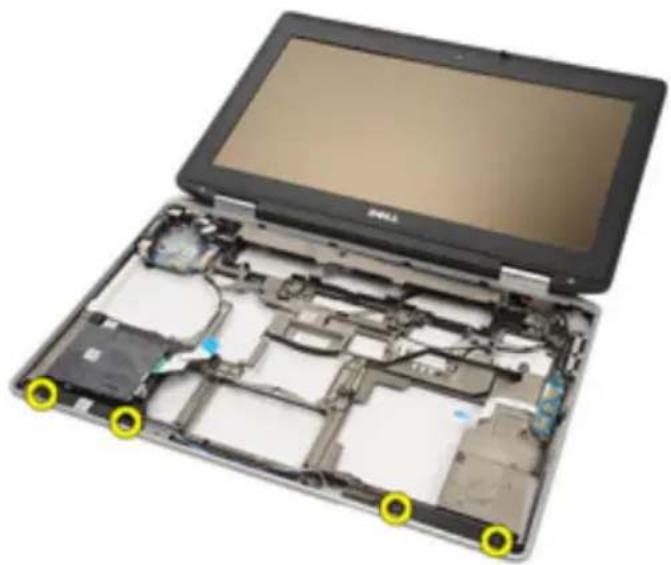
natural_image
Laptop with exposed internal circuitry and yellow circular annotations highlighting specific components (no text or symbols present)- Unthread the speaker cable.
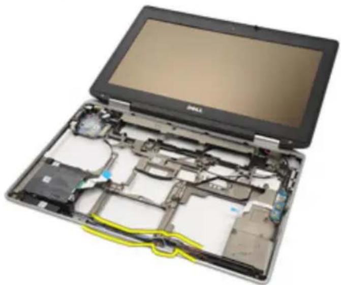
natural_image
Laptop with exposed internal circuitry and yellow cable, no visible text or symbols- Remove the speaker from the system.
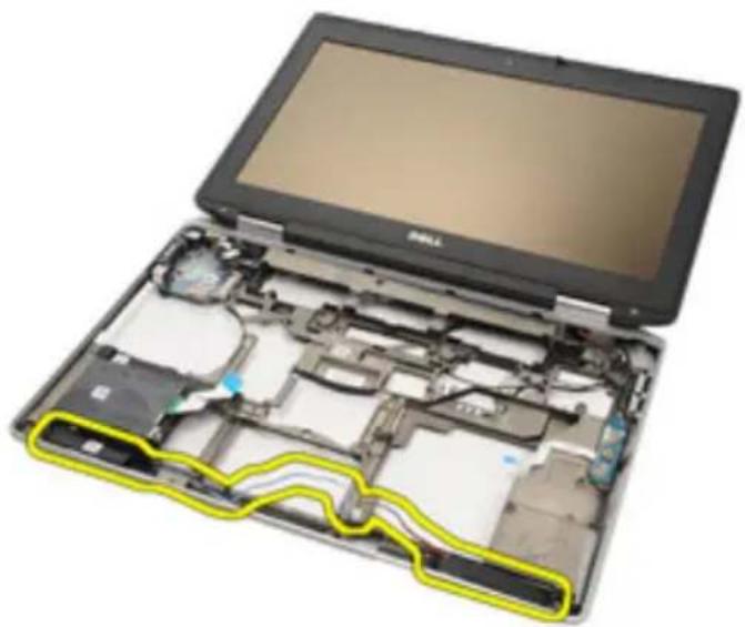
natural_image
Laptop with exposed internal components and a yellow outline highlighting a section (no text or symbols visible)Installing the Speakers
- Place the speaker back into the system.
- Route the speaker cable.
-
Tighten the screws securing the speaker assembly.
-
Install the System Board.
-
Install the ExpressCard Cage.
-
Install the Palmrest Assembly.
-
Install the Modem Card.
-
Install the Keyboard.
-
Install the Keyboard Trim.
-
Install the Bluetooth Card.
-
Install the Heat Sink and Processor.
-
Install the Coin Cell Battery.
-
Install the WWAN Card.
-
Install the WLAN Card.
-
Install the Hard Drive.
-
Install the Memory.
-
Install the Optical Drive.
-
Install the ExpressCard.
-
Install the Base Cover.
-
Install the SD Card.
-
Install the Battery.
-
Install the ATG Port Cover(only for E6420 ATG systems).
-
Install the ATG Handle(only for E6420 ATG systems).
-
Follow the procedures in After Working Inside Your Computer
Modem Connector 27
Removing the Modem Connector
- Follow the procedures in Before Working On Your Computer.
- Remove the ATG Handle (only for E6420 ATG systems).
- Remove the ATG Port Cover (only for E6420 ATG systems).
- Remove the Battery.
- Remove the Secure Digital Card.
- Remove the Base Cover.
- Remove the Modem Connector Plug.
- Remove the ExpressCard.
- Remove the Optical Drive.
- Remove the Memory.
- Remove the Hard Drive.
- Remove the WLAN Card.
- Remove the WWAN Card.
- Remove the Coin Cell Battery.
- Remove the Heat Sink and Processor.
- Remove the Bluetooth Card.
- Remove the Keyboard Trim.
- Remove the Keyboard.
- Remove the Modem Card.
- Remove the Palmrest Assembly.
- Remove the ExpressCard Cage.
- Remove the System Board.
- Unthread the modem cable.
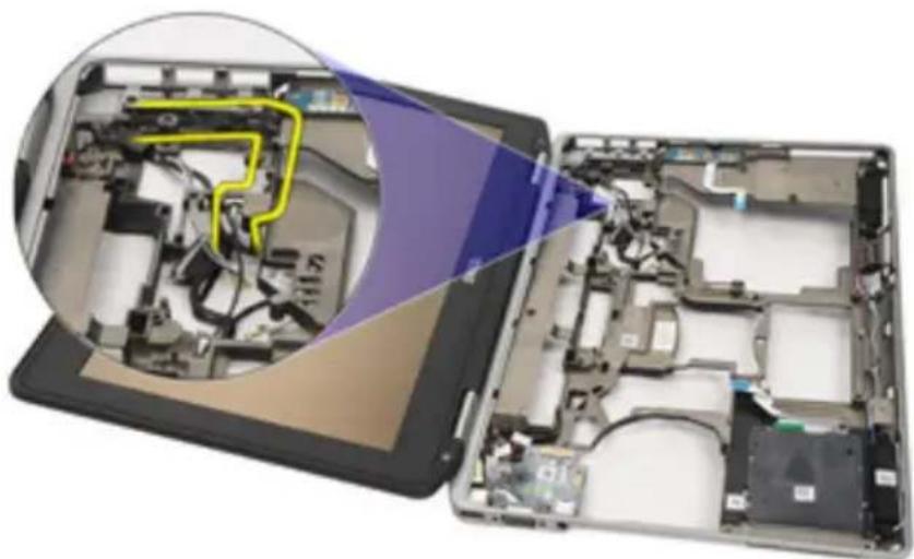
natural_image
Interior view of a laptop showing internal circuitry and battery pack (no text or symbols visible)- Unthread the video and wireless antenna cables.
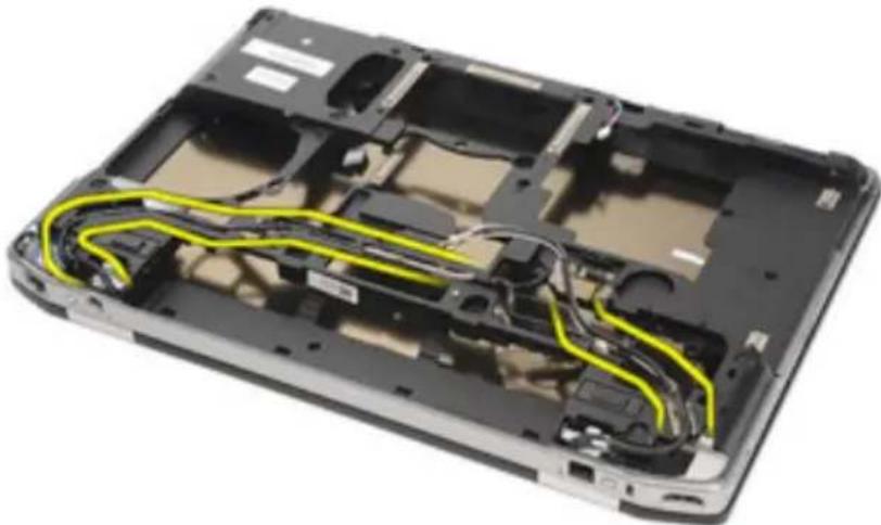
natural_image
Interior view of a laptop chassis showing exposed circuitry and wiring (no text or symbols visible)- Unthread the modem cable.
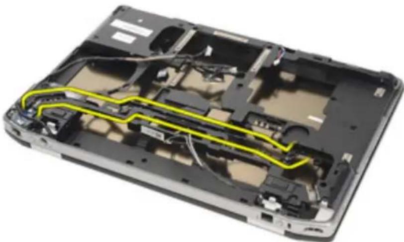
natural_image
Laptop interior showing exposed circuitry and wiring, no text or symbols visible- Pull out the end of the modem-to-motherboard connector.
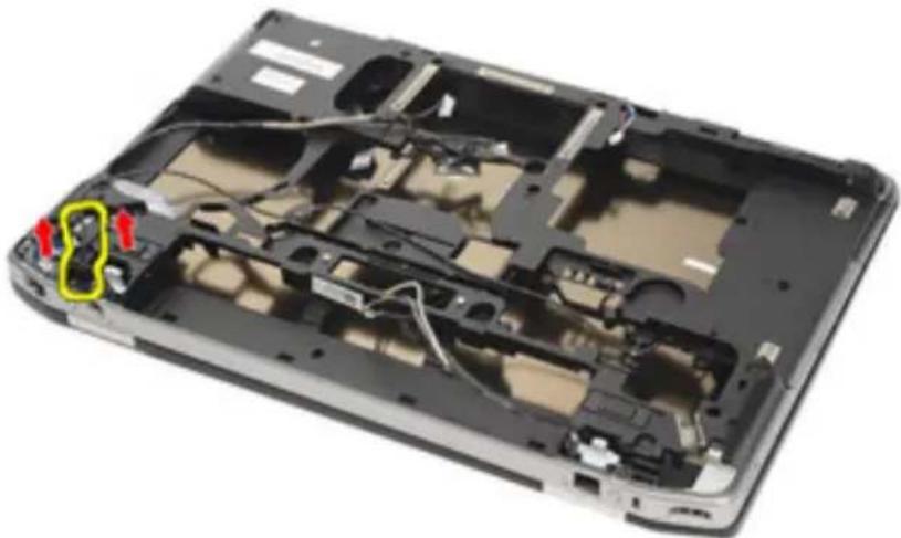
natural_image
Laptop interior showing exposed circuitry and wiring, with red arrows highlighting specific components (no text or symbols visible)- Remove screw from modem cable holder.
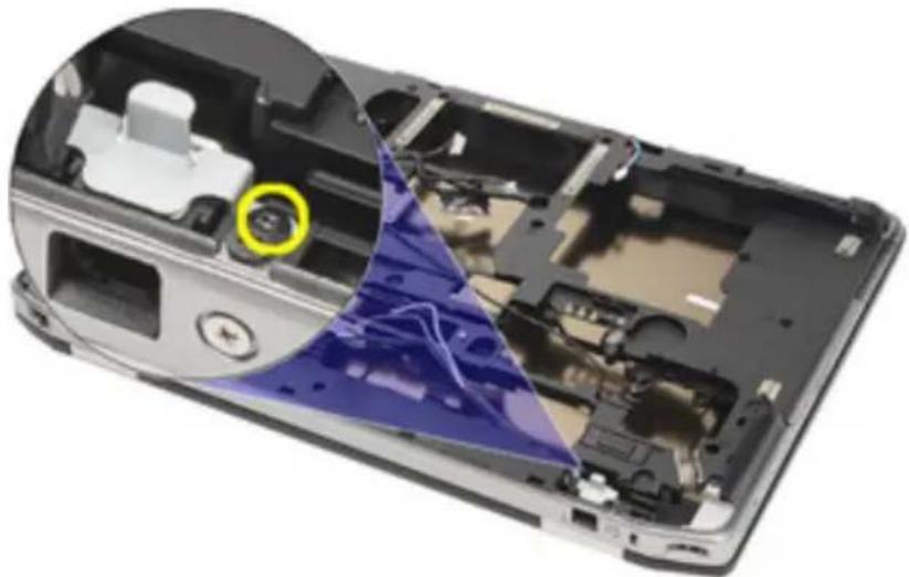
natural_image
Interior view of a device showing internal components and a highlighted blue triangular area (no text or symbols visible)- Remove modem cable holder.
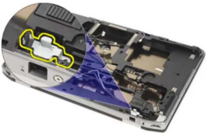
natural_image
Interior view of a smartphone showing internal components and a highlighted yellow area (no text or symbols visible)- Remove the whole modem cable assembly by pulling it out from the base.
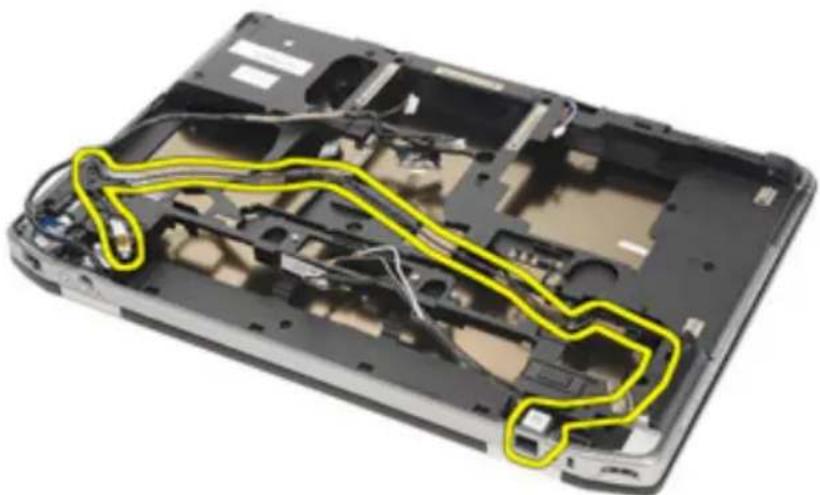
natural_image
Laptop chassis interior showing exposed internal components with yellow outline highlighting the structure (no text or symbols)Installing the Modem Connector
- Place the modem cable assembly into the base.
- Place the modem cable holder.
- Tighten the screw securing the modem cable holder.
- Connect the end of the modem-to-motherboard connector.
- Route the modem cable.
- Route the video and wireless antenna cables.
- Install the System Board.
- Install the ExpressCard Cage
- Install the Palmrest Assembly.
- Install the Modem Card.
- Install the Keyboard.
- Install the Keyboard Trim.
- Install the Bluetooth Card.
- Install the Heat Sink and Processor.
- Install the Coin Cell Battery.
- Install the WWAN Card.
- Install the WLAN Card.
- Install the Hard Drive.
- Install the Memory.
- Install the Optical Drive.
- Install the ExpressCard.
- Install the Modem Connector Plug.
- Install the Base Cover.
- Install the SD Card.
- Install the Battery.
- Install the ATG Port Cover(only for E6420 ATG systems).
- Install the ATG Handle(only for E6420 ATG systems).
- Follow the procedures in After Working Inside Your Computer.
Input/Output Panel 28
Removing the Input/Output (I/O) Board
- Follow the procedures in Before Working On Your Computer.
- Remove the ATG Handle (only for E6420 ATG systems).
- Remove the ATG Port Cover (only for E6420 ATG systems).
- Remove the Battery.
- Remove the Secure Digital Card.
- Remove the Base Cover.
- Remove the ExpressCard.
- Remove the Optical Drive.
- Remove the Memory.
- Remove the Hard Drive.
- Remove the WLAN Card.
- Remove the WWAN Card.
- Remove the Coin Cell Battery.
- Remove the Heat Sink and Processor.
- Remove the Bluetooth Card.
- Remove the Keyboard Trim.
- Remove the Keyboard.
- Remove the Modem Card.
- Remove the Palmrest Assembly.
- Remove the ExpressCard Cage.
- Remove the screw securing the I/O board to the computer.
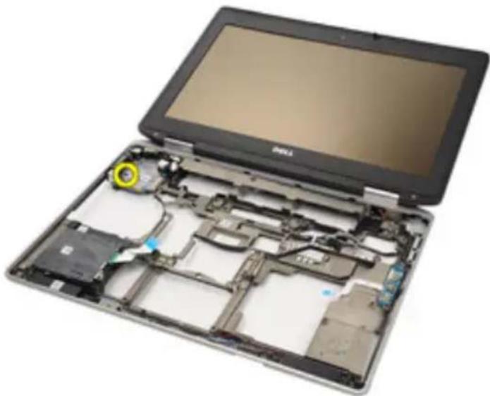
natural_image
Interior view of a fully open tablet device showing internal circuitry and components (no text or symbols visible)- Remove the I/O board from the computer.
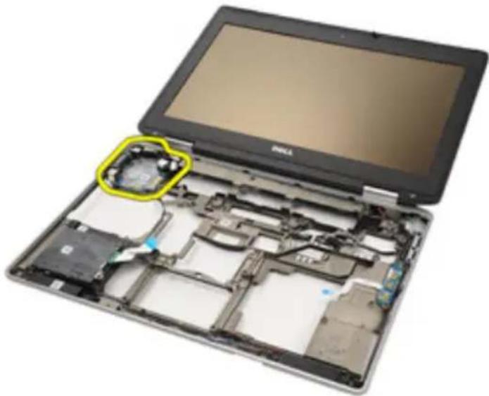
natural_image
Laptop with exposed internal components and a highlighted case (no text or symbols visible)Installing the Input/Output (I/O) Board
- Replace the I/O board in the computer.
-
Tighten the screw securing the I/O board to the computer.
-
Install the System Board.
-
Install the ExpressCard Cage
-
Install the Palmrest Assembly.
-
Install the Modem Card.
-
Install the Keyboard.
-
Install the Keyboard Trim.
-
Install the Bluetooth Card.
-
Install the Heat Sink and Processor.
-
Install the Coin Cell Battery.
-
Install the WWAN Card.
-
Install the WLAN Card.
-
Install the Hard Drive.
-
Install the Memory.
-
Install the Optical Drive.
-
Install the Express Card.
-
Install the Base Cover.
-
Install the SD Card.
-
Install the Battery.
-
Install the ATG Port Cover(only for E6420 ATG systems).
-
Install the ATG Handle(only for E6420 ATG systems).
-
Follow the procedures in After Working Inside Your Computer.
DC-In Port 29
Removing DC-in Port
- Follow the procedures in Before Working On Your Computer.
- Remove the ATG Handle (only for E6420 ATG systems).
- Remove the ATG Port Cover (only for E6420 ATG systems).
- Remove the Battery.
- Remove the Secure Digital Card.
- Remove the Base Cover.
- Remove the ExpressCard.
- Remove the Optical Drive.
- Remove the Memory.
- Remove the Hard Drive.
- Remove the WLAN Card.
- Remove the WWAN Card.
- Remove the Coin Cell Battery.
- Remove the Heat Sink and Processor.
- Remove the Bluetooth Card.
- Remove the Keyboard Trim.
- Remove the Keyboard.
- Remove the Modem Card.
- Remove the Palmrest Assembly.
- Remove the ExpressCard Cage.
- Remove the System Board.
- Remove the screw securing the DC-in bracket.
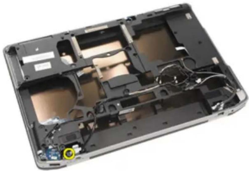
natural_image
Interior view of a laptop case showing exposed circuitry and wiring (no text or symbols visible)- Remove the DC-in bracket.
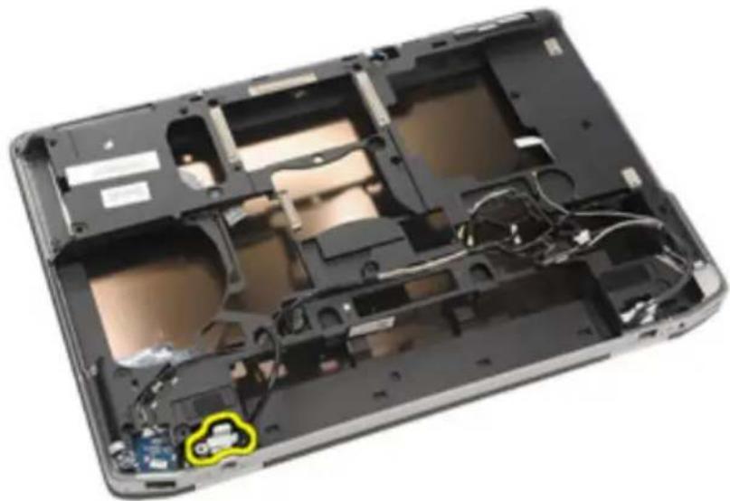
natural_image
Interior view of a laptop case showing exposed circuitry and internal components (no text or symbols visible)- Remove the DC-in cable from the system.
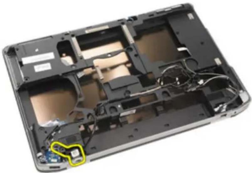
natural_image
Interior view of a laptop case showing exposed casing, circuitry, and internal components (no text or symbols visible)- Push in the DC-in trim and remove it from the system.
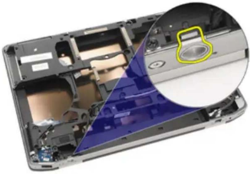
natural_image
Interior view of a laptop case showing internal components and a close-up of the screen (no text or symbols visible)Installing DC-In Port
-
Push the DC-in trim and place it into the system.
-
Place the DC-in cable into the system.
-
Insert the DC-in bracket.
-
Tighten the screw securing the DC-in bracket.
-
Install the System Board.
-
Install the ExpressCard Cage.
-
Install the Palmrest Assembly.
-
Install the Modem Card.
-
Install the Keyboard.
-
Install the Keyboard Trim.
-
Install the Bluetooth Card.
-
Install the Heat Sink and Processor.
-
Install the Coin Cell Battery.
-
Install the WWAN Card.
-
Install the WLAN Card.
-
Install the Hard Drive.
-
Install the Memory.
-
Install the Optical Drive.
-
Install the ExpressCard.
-
Install the Base Cover.
-
Install the SD Card.
-
Install the Battery.
-
Install the ATG Port Cover(only for E6420 ATG systems).
-
Install the ATG Handle(only for E6420 ATG systems).
-
Follow the procedures in After Working Inside Your Computer
Display Assembly 30
Removing the Display Assembly
- Follow the procedures in Before Working On Your Computer.
- Remove the ATG Handle (only for E6420 ATG systems).
- Remove the ATG Port Cover (only for E6420 ATG systems).
- Remove the Battery.
- Remove the Secure Digital Card.
- Remove the Base Cover.
- Remove the ExpressCard.
- Remove the Optical Drive.
- Remove the Memory.
- Remove the Hard Drive.
- Remove the WLAN Card.
- Remove the WWAN Card.
- Remove the Coin Cell Battery.
- Remove the Heat Sink and Processor.
- Remove the Bluetooth Card.
- Remove the Keyboard Trim.
- Remove the Keyboard.
- Remove the Modem Card.
- Remove the Palm rest Assembly.
- Remove the ExpressCard Cage.
- Remove the System Board.
- Remove the DC-in port.
- Remove the screws securing the display assembly to the computer.
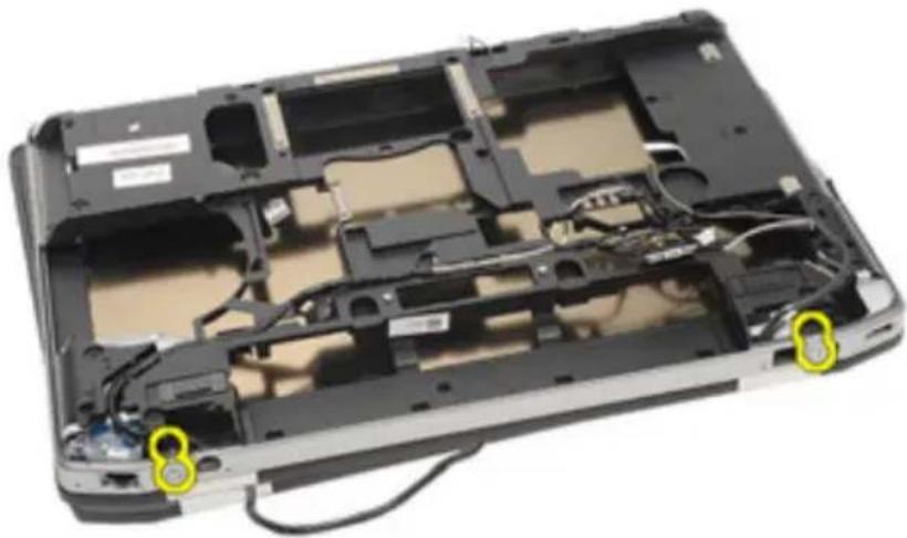
natural_image
Interior view of a laptop case showing exposed internal components and cable, with two yellow circular markers highlighting specific areas (no text or symbols present)- Unthread the antennas, video, and camera connectors.
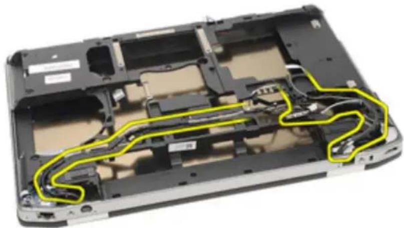
natural_image
Interior view of a laptop chassis showing exposed circuitry and wiring (no text or symbols visible)- Lift up the whole bottom base while threading the cable down via the bottom base.
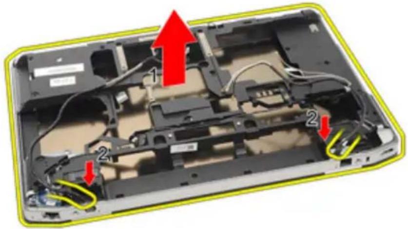
natural_image
Laptop interior showing exposed circuit board with red arrows indicating components (no text or symbols)Installing the Display Assembly
- Align the display assembly into its original position on the computer.
- Route the antennas, video, and camera connectors.
- Install the DC in port
- Install the System Board.
- Install the ExpressCard Cage
- Install the Palmrest Assembly.
- Install the Modem Card.
- Install the Keyboard.
- Install the Keyboard Trim.
- Install the Bluetooth Card.
- Install the Heat Sink and Processor.
- Install the Coin Cell Battery.
- Install the WWAN Card.
- Install the WLAN Card.
- Install the Hard Drive.
- Install the Memory.
- Install the Optical Drive.
- Install the ExpressCard.
- Install the Base Cover.
- Install the Secure Digital (SD) Card.
- Install the Battery.
- Install the ATG Port Cover(only for E6420 ATG systems).
- Install the ATG Handle(only for E6420 ATG systems).
- Follow the procedures in After Working Inside Your Computer.
Display Hinges 31
Removing the Display Hinge Covers
- Follow the procedures in Before Working On Your Computer.
- Remove the ATG Handle (only for E6420 ATG systems).
- Remove the ATG Port Cover (only for E6420 ATG systems).
- Remove the Battery.
- Remove the Secure Digital Card.
- Remove the Base Cover.
- Remove the ExpressCard.
- Remove the Optical Drive.
- Remove the Memory.
- Remove the Hard Drive.
- Remove the WLAN Card.
- Remove the WWAN Card.
- Remove the Coin Cell Battery.
- Remove the Heat Sink and Processor.
- Remove the Bluetooth Card.
- Remove the Keyboard Trim.
- Remove the Keyboard.
- Remove the Modem Card.
- Remove the Palmrest Assembly.
- Remove the ExpressCard Cage.
- Remove the System Board.
- Remove the DC-in port.
- Remove the Display Assembly.
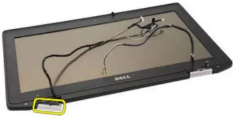
- Pry the display hinge cover from the left hinge.
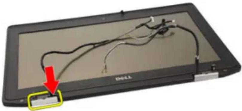
natural_image
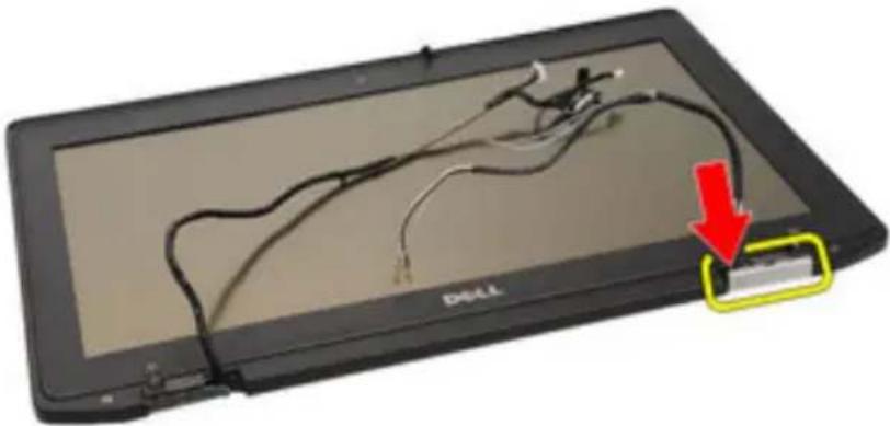
Close-up of a black Dell tablet with cable connectors and a red arrow pointing to a device component (no text or symbols visible)- Remove the display hinge cover from the left hinge.
natural_image
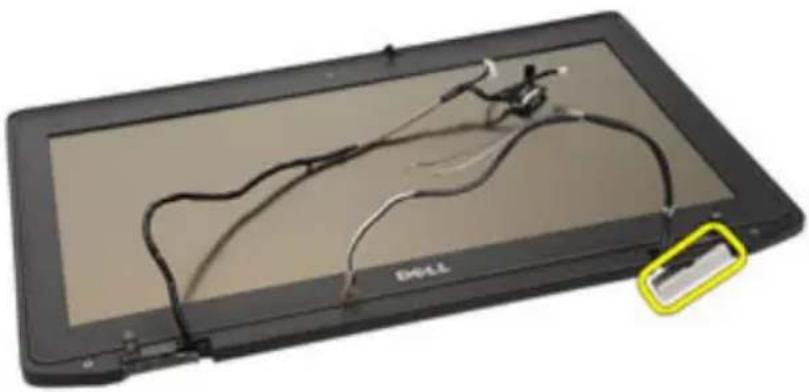
Black Dell laptop with visible internal circuitry and a highlighted cable (no text or symbols on screen)- Pry the display hinge cover from the right hinge.
natural_image
Black-and-white photo of a Drell tablet with visible cable and connector, showing a red arrow pointing to a device (no text or symbols on the device itself)- Remove the display hinge cover from the right hinge.
natural_image
Exterior view of a black electronic device with visible traces and a small yellow tag (no text or symbols)Installing the Display Hinge Covers
- Place the display hinges in the appropriate positions.
- Replace the display hinge cover to the computer.
- Install the Display Assembly.
- Install the DC-in port
- Install the System Board.
- Install the ExpressCard Cage
- Install the Palmrest Assembly.
- Install the Modem Card.
- Install the Keyboard.
- Install the Keyboard Trim.
- Install the Bluetooth Card.
- Install the Heat Sink and Processor.
- Install the Coin Cell Battery.
- Install the WWAN Card.
- Install the WLAN Card.
- Install the Hard Drive.
- Install the Memory.
- Install the Optical Drive.
- Install the ExpressCard.
- Install the Base Cover.
- Install the SD Card.
- Install the Battery.
- Install the ATG Port Cover(only for E6420 ATG systems).
- Install the ATG Handle(only for E6420 ATG systems).
- Follow the procedures in After Working Inside Your Computer
Display Bezel 32
Removing the Display Bezel
-
Follow the procedures in Before Working On Your Computer.
-
Remove the Battery.
-
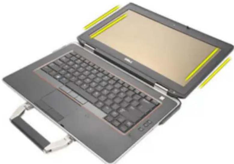
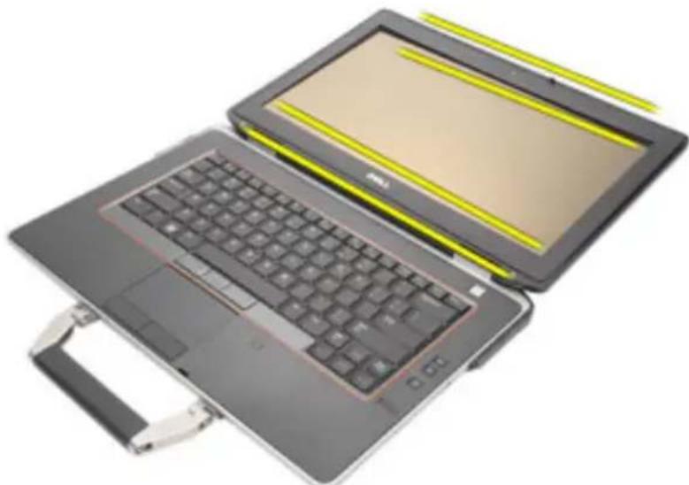
Pry the left and right edges of the display bezel.
natural_image
Two open laptop devices with visible keyboard and screen, placed side by side (no text or symbols)- Work along to the top and bottom edges of the display bezel.
natural_image
Two open laptop cases with visible keyboard and screen, no text or symbols present- Remove the display bezel.
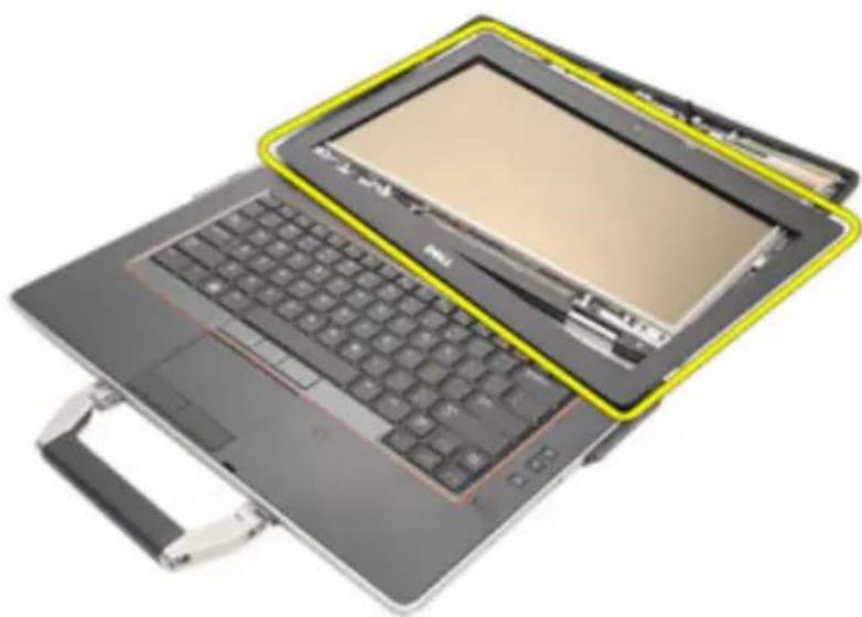
natural_image
Laptop with open keyboard and highlighted screen area (no text or symbols visible)Installing the Display Bezel
- Place the display bezel into the system.
- Work along to the top and bottom edges of the display bezel.
- Press the left and right edges of the display bezel.
- Install the Battery.
- Follow the procedures in After Working Inside Your Computer.
Display Panel 33
Removing the Display Panel
- Follow the procedures in Before Working On Your Computer.
- Remove the Battery.
- Remove the Display Bezel.
- Remove the screws securing the display panel to the display assembly.
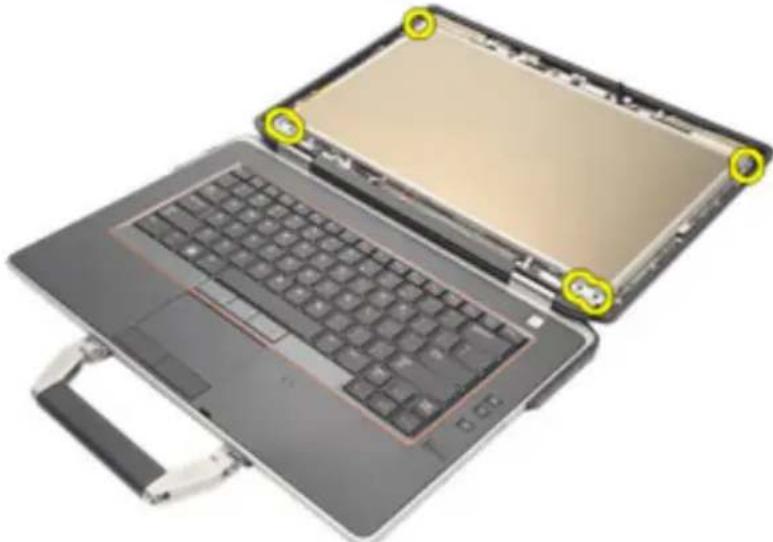
natural_image
Laptop with open case showing front panel and keyboard, no visible text or symbols- Flip the display panel over.
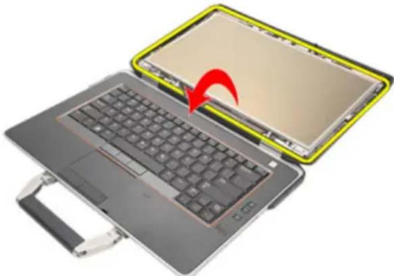
natural_image
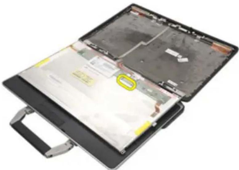
Laptop with open circuit board and keyboard, showing a red arrow indicating the next screen (no text or symbols visible)- Disconnect the Low-Voltage Differential Signaling (LVDS) cable connector tape from the display panel.
natural_image
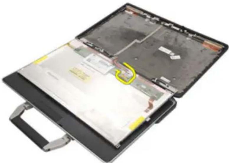
Open laptop case with visible internal components and a yellow oval highlight on the cover (no text or symbols)- Disconnect the Low-Voltage Differential Signaling (LVDS) cable from the display panel.
natural_image
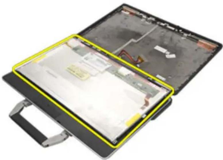
Open laptop case with visible internal components and a yellow curved line indicating a highlighted area (no text or symbols)- Remove the display panel from the display assembly.
natural_image
Open laptop case with exposed internal components and a yellow bounding box highlighting the interior (no text or symbols visible)Installing the Display Panel
- Align the display panel in its original position on the display assembly.
- Connect the Low-Voltage Differential Signaling (LVDS) cable to the display panel.
-
Tighten the screws securing the display panel to the display assembly.
-
Install the LCD Bezel
-
Install the Battery.
-
Follow the procedures in After Working Inside Your Computer.
Display Bracket 34
Removing the Display Bracket
- Follow the procedures in Before Working On Your Computer.
- Remove the Battery.
- Remove the Display Bezel.
- Remove the Display Panel.
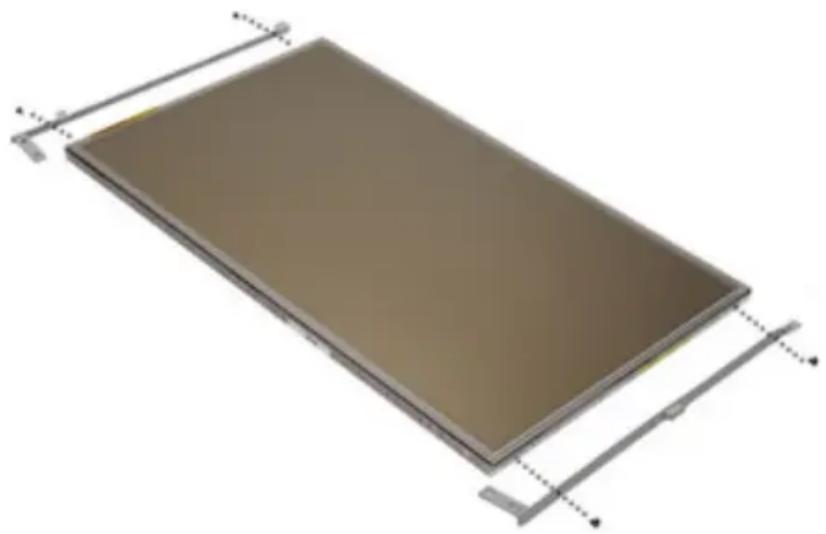
- Remove the screws from each side of the display panel and remove the display brackets.
natural_image
3D rendering of a rectangular electronic component with metal frame and mounting brackets (no text or symbols)Installing the Display Bracket
- Place the display brackets and tighten the screws on either side of the display panel.
- Install the Display Panel.
- Install the LCD Bezel.
- Install the Battery.
- Follow the procedures in After Working Inside Your Computer.
Camera 35
Removing the Camera
- Follow the procedures in Before Working On Your Computer.
- Remove the Battery.
- Remove the Display Bezel.
- Remove the Display Panel
- Disconnect the camera cable from the camera.
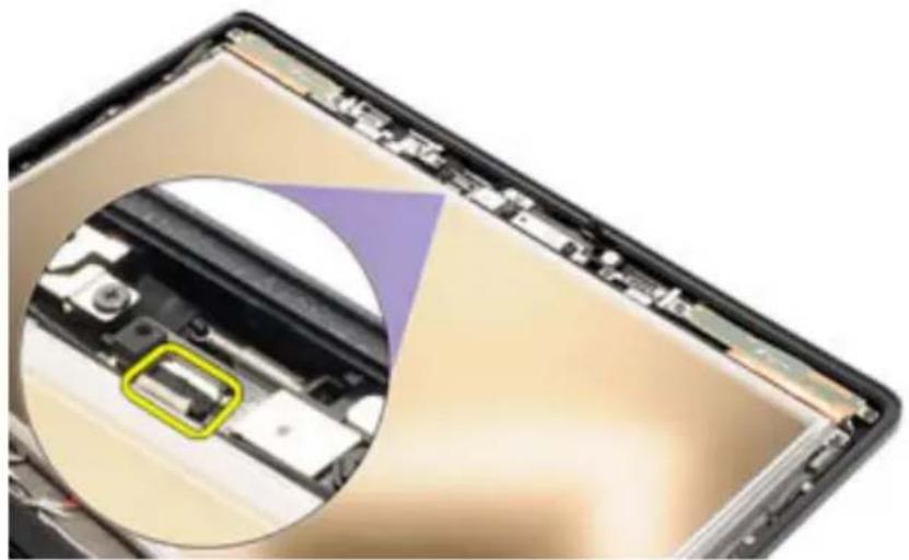
natural_image
Close-up of a smartphone showing internal components and a magnified view of the device's interior (no text or symbols visible)- Remove the captive screw securing the camera to the display assembly.
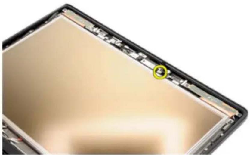
natural_image
Close-up of a smartphone's front panel showing the lid and screen (no text or symbols visible)- Remove the camera from the display assembly.
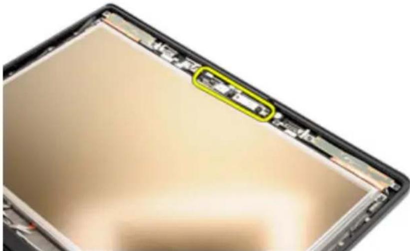
natural_image
Close-up of a smartphone's front panel showing internal components and battery casing (no text or symbols visible)Installing the Camera
- Place the camera module in its original position in the display assembly.
- Tighten the screw securing the camera to the display assembly.
- Connect the camera cable to the camera.
- Install the Display Panel.
- Install the Display Bezel.
- Install the Battery.
- Follow the procedures in After working inside your computer.
Specifications 36
Technical Specifications

NOTE: Offerings may vary by region. The following specifications are only those required by law to ship with your computer. For more information regarding the configuration of your computer, click Start → Help and Support and select the option to view information about your computer.
System Information
Chipset Intel Mobile Express Series 6 chipset
DRAM bus width 64-bit
Flash EPROM SPI 32 Mbits
PCIe Gen1 bus 100 MHz
Processor
Types
- Intel Core i3 series (available only with Latitude E6420 only)
- Intel Core i5 series with Turbo Boost technology 2.0
- Intel Core i7 series with Turbo Boost technology 2.0
L2 cache up to 6 MB
External bus frequency 1333 MHz
Memory
Memory connector two SODIMM slots
Memory capacity 1 GB, 2 GB, or 4 GB
Memory type DDR3 SDRAM (1333 MHz)
Minimum memory 2 GB
Maximum memory 8 GB
Audio
Type four-channel high definition audio
Controller IDT 92HD90
Stereo conversion 24-bit (analog-to-digital and digital-to-analog)
Interface:
Internal high definition audio
External microphone-in/stereo headphones/external speakers connector
Speakers two
Internal speaker amplifier 0.5 W (typical) per channel
Volume controls keyboard function keys and program menus
Video
Video type
- integrated on system board
- discrete
Data bus:
UMA integrated video
Discrete
- PCI-E x16 Gen1
- PCI-E x16 Gen2
Controller:
UMA
Latitude E6420 Intel HD Graphics
Latitude E6420 ATG Intel HD Graphics 3000
Discrete NVIDIA NVS 4200M Discrete Graphics (512
MB DDR3)
Communications
Network adapter 10/100/1000 Mbps Ethernet LAN
Communications
Wireless internal wireless local area network (WLAN) and wireless wide area network (WWAN)
Ports and Connectors
Audio one microphone connector/stereo headphones/ external speakers connector
Video
- one 15-pin VGA connector
• one 19-pin HDMI connector
Network adapter one RJ-45 connector
USB three 4-pin USB 2.0-compliant connectors and one eSATA/USB 2.0-compliant connector
Memory card reader one 5-in-1 memory card reader
Contactless Smart Card
Supported Smart Cards/Technologies ISO14443A — 106 kbps, 212 kbps, 424 kbps, and 848 kbps ISO14443B — 106 kbps, 212 kbps, 424 kbps, and 848 kbps ISO15693 HID iClass FIPS201 NXP Desfire
Display
Type white Light Emitting Diode (WLED) display
Size 14.0 inch high definition (HD)
Active area (X/Y) 309.40 mm x 173.95 mm
Dimensions:
Height 192.50 mm (7.58 inches)
Width 324.00 mm (12.76 inches)
Diagonal 355.60 mm (14.00 inches)
Maximum resolution 1366 x 768 pixels at 263 K colors
Maximum Brightness
Latitude E6420 200 nits
Display
| Latitude E6420 ATG 730 nits |
| Operating angle 0° (closed) to 135° |
| Refresh rate 60 Hz |
| Minimum Viewing angles: |
| Latitude E6420 |
| Horizontal +/- 40° |
| Vertical +10°/-30° |
| Latitude E6420 ATG |
| Horizontal +/- 50° |
| Vertical +/- 40° |
| Pixel pitch 0.2265 mm |
Keyboard
| Number of keys United States: 86 keys, United Kingdom: 87keys, Brazil: 87 keys, and Japan: 90 keys |
| Layout QWERTY/AZERTY/Kanji |
Touchpad
| Active Area: |
| X-axis 80.00 mm |
| Y-axis 40.70 mm |
Battery
Type
- 4-cell "smart" lithium ion (available only with Latitude E6420 only)
- 6-cell "smart" lithium ion
• 9-cell "smart" lithium ion
Dimensions:
4-cell and 6-cell
Battery
| Depth 48.08 mm (1.90 inches) | |
| Height 20.00 mm (0.79 inch) | |
| Width 208.00 mm (8.19 inches) | |
| 9-cell | |
| Depth 71.79 mm (2.83 inches) | |
| Height 20.00 mm (0.79 inch) | |
| Width 214.00 mm (8.43 inches) | |
| Weight: | |
| 6-cell 345.00 g (0.76 lb) | |
| 9-cell 524.00 g (1.16 lb) | |
| Charge time for a 6-cell battery with computer off | approximately 1 hour to 80% capacity and 2 hours to 100% capacity. |
| Voltage | |
| 4-cell 14.80 VDC | |
| 6-cell and 9-cell 11.10 VDC | |
| Temperature range: | |
| Latitude E6420 | |
| Operating 0 °C to 35 °C (32 °F to 95 °F) | |
| Non-Operating -40 °C to 65 °C (-40 °F to 149 °F) | |
| Latirude E6420 ATG | |
| Operating 0 °C to 60 °C (32 °F to 140 °F) | |
| Non-Operating -51 °C to 71 °C (-59 °F to 159 °F) | |
| Coin-cell battery 3 V CR2032 lithium coin cell | |
AC Adapter
| Latitude E6420 Latitude E6420 ATG | |
| Type 65 W, 90 W, and 150 W | 90 W |
AC Adapter

NOTE: 65 W AC
adapter is
available only for
computers with
integrated video
card.
Input voltage 100 VAC to 240 VAC 100 VAC to 240 VAC
Input current 1.50 A/1.60 A/1.70 A/ 1.50 A/1.60 A/1.70 A
(maximum) 2.10 A
Input frequency 50 Hz to 60 Hz 50 Hz to 60 Hz
Output power 65 W, 90 W, and 150 90 W
W
Output current 3.34 A, 4.62 A and 7.70 4.62 A (continuous)
A (continuous)
Rated output 19.5 +/- 1.0 VDC 19.5 +/- 1.0 VDC
voltage
Temperature
range:
Operating 0 °C to 40 °C (32 °F to 0 °C to 40 °C (32 °F to 104 °F)
104 °F)
Non- -40^ to 70^ ( -40^ -40^ to 70^ ( -40^ to 158^ )
Operating to 158 °F)
Physical
Latitude E6420
Height 26.90 mm to 32.40 mm (1.06 inches to 1.27
inches)
Width 352.00 mm (13.86 inches)
Depth 241.00 mm (9.49 inches)
Weight (with 4-cell battery) 2.07 kg (4.56 lb)
Latitude E6420 ATG
Physical
| Height 29.00 mm to 37.70 mm (1.14 inches to 1.48 inches) | |
| Width 357.30 mm (14.07 inches) | |
| Depth 246.50 mm (9.70 inches) | |
| Weight (with 6-cell battery and air bay) | 2.69 kg (5.93 lb) |
Environmental
| Temperature: |
| Latitude E6420 |
| Operating 0 °C to 35 °C (32 °F to 95 °F) |
| Storage -40 °C to 65 °C (-40 °F to 149 °F) |
| Latitude E6420 ATG |
| Operating 0 °C to 60 °C (32 °F to 140 °F)* |
| Storage -51 °C to 71 °C (-59 °F to 159 °F) |
| * Tested configuration is without the optical drive |
| Relative humidity (maximum): |
| Operating 10 % to 90 % (noncondensing) |
| Storage 5 % to 95 % (noncondensing) |
| Altitude (maximum): |
| Operating -15.2 m to 3048 m (-50 ft to 10,000 ft) |
| Non-Operating -15.2 m to 10,668 m (-50 ft to 35,000 ft) |
| Airborne contaminant level G1 as defined by ISA-71.0 |
System Setup 37
Setup Overview
System Setup allows you to:
- change the system configuration information after you add, change, or remove any hardware in your computer.
- set or change a user-selectable option such as the user password.
- read the current amount of memory or set the type of hard drive installed.
Before you use System Setup, it is recommended that you write down the System Setup screen information for future reference.

CAUTION: Unless you are an expert computer user, do not change the settings for this program. Certain changes can cause your computer to work incorrectly.
Entering System Setup
- Turn on (or restart) your computer.
- When the blue DELL logo is displayed, you must watch for the F2 prompt to appear.
- Once the F2 prompt appears, press
immediately.

NOTE: The F2 prompt indicates that the keyboard has initialized. This prompt can appear very quickly, so you must watch for it to display, and then press
- If you wait too long and the operating system logo appears, continue to wait until you see the Microsoft Windows desktop. Then, shut down your computer and try again.
System Setup Menu
The following sections describe the menu options for the System Setup program:
General
Option Description
System Information This section lists the primary hardware
features of your computer.
- System Information
- Memory Information
- Processor Information
- Device Information
Battery Information Displays the battery status and the type of
AC adapter connected to the computer.
Boot Sequence Allows you to change the order in which
the computer attempts to find an operating system.
- Diskette Drive
- Internal HDD
- USB Storage Device
- CD/DVD/CD-RW Drive
- Onboard NIC
- Cardbus NIC
You can also choose the Boot List option. The options are:
- Legacy
• UEFI
Date/Time
Allows you to change the date and time.
System Configuration
Option Description

NOTE: System Configuration contains options and settings related to integrated system devices. Depending on your computer and installed devices, the items listed in this section may or may not appear.
Integrated NIC Allows you to configure the integrated
network controller. The options are:
- Disabled
- Enabled
- Enabled w/PXE
Default Setting: Enabled w/PXE
System Management Allows you to control the systems
management mechanism. The options are:
- Disabled
• DASH/ASF 2.0
Default Setting: DASH/ASF 2.0
Parallel Port Allows you to configure the parallel port
on the docking station. The options are:
- Disabled
• AT
• PS2
• ECP
Default Setting: AT
Serial Port Allows you to configure the integrated
serial port. The options are:
- Disabled
• COM1
• COM2
• COM3
• COM4
Default Setting: COM1
SATA Operation Allows you to configure the internal SATA
hard-drive controller. The options are:
- Disabled
• ATA
• AHCI
- RAID On
Default Setting: RAID On

NOTE: SATA is configured to support RAID mode.
USB Controller Allows you to control the USB controller.
The options are:
- Enable Boot Support
- Enable External USB Port
Default Setting: Enable USB Controller and Enable External USB Port
Miscellaneous Devices Allows you to enable or disable the following devices:
- Internal Modem
- Microphone
- eSATA Ports
- Hard Drive Free Fall Protection
- Module Bay
- ExpressCard
- Camera
You can also enable or disable:
• Media Card and 1394
- Enable Media Card only
- Disable Media Card and 1394
Default Setting: Media Card and 1394
Keyboard illumination
Allows you to configure the keyboard illumination feature. The options are:
- Disabled
- Level is 25%
- Level is 50%
- Level is 75%
- Level is 100%
Default Setting: Level is 25%
Drives Allows you to configure the SATA drives
on board. The options are:
- SATA-0
- SATA-1
• SATA-4
- SATA-5
Default Setting: All drives are enabled.
Video
Option Description
LCD Brightness Allows you to set the display brightness depending on the power source (On Battery and On AC).
Enable Optimus This option enables or disables the Nvidia Optimus Technology applicable to Windows 7 only.
Security
Option Description
Admin Password Allows you to set, change, or delete the administrator (admin) password.

NOTE: You must set the admin password before you set the system or hard drive password.

NOTE: Deleting the admin password automatically deletes the system password and the hard drive password.

NOTE: Successful password changes take effect immediately.
Default Setting: Not set
System Password
Allows you to set, change, or delete the system password.

NOTE: Successful password changes take effect immediately.
Default Setting: Not set
Internal HDD-0 Password Allows you to set or change the system's internal hard-disk drive.

NOTE: Successful password changes take effect immediately.
Default Setting: Not set
Password Bypass Allows you to enable or disable the
permission to bypass the System and the Internal HDD password, when they are set. The options are:
- Disabled
- Reboot bypass
Default Setting: Disabled
Password Change Allows you to enable the disable
permission to the System and Hard Drive passwords when the admin password is set.
Default Setting: Allow Non-Admin Password Changes is selected
Strong Password Allows you to enforce the option to always
set strong passwords.
Default Setting: Disabled
OROM Keyboard Access Allows you to set an option to enter the
Option ROM Configuration screens using hotkeys during boot. The options are:
- Enable
- One Time Enable
- Disable
Default Setting: Enable
TPM Security Allows you to enable the Trusted Platform
Module (TPM) during POST.
Default Setting: Disabled
Computrace (R) Allows you to activate or disable the
optional Computrace software. The options are:
- Deactivate
- Disable
- Activate

NOTE: The Activate and Disable options will permanently activate or disable the feature and no further changes will be allowed.
Default Setting: Deactivate
CPU XD Support Allows you to enable the Execute Disable
mode of the processor.
Default Setting: Enabled
Non-Admin Setup Changes Allows you to determine whether changes
to the setup options are allowed when an
Administrator Password is set. If disabled, the setup options are locked by the admin password.
Default Setting: Disabled
Password Configuration Allows you to determine the minimum and
maximum length of Administrator and
System passwords.
Admin Setup Lockout Allows you to prevent users from entering
Setup when an Administrator password is set.
Default Setting: Disabled
Performance
Option Description
Multi Core Support Allows you to enable or disable multi-core
support for the processor. The options are:
• All
• 1
• 2
Default Setting: All
Intel SpeedStep Allows you to enable or disable the Intel
SpeedStep feature.
Default Setting: Enabled
C-States Control Allows you to enable or disable the
additional processor sleep states.
| Default Setting: The options C states, C3, C6, Enhanced C-states, and C7 options are selected/enabled. | |
| Limit CPUID Allows you to limit the maximum value the processor Standard CPUID Function will support. Default Setting: Enable CPUID Limit | |
| Intel TurboBoost Allows you to enable or disable the Intel TurboBoost mode of the processor. Default Setting: Enabled | |
| HyperThread Control Allows you to enable or disable the HyperThreading in the processor. Default Setting: Enabled | |
Power Management
Option Description
| AC Behavior Allows you to enable or disable the computer from turning on automatically when an AC adapter is connected.Default Setting: Wake on AC is not selected. | |
| Auto On Time Allows you to set the time at which the computer must turn on automatically. The options are:DisabledEvery DayWeekdaysDefault Setting: Disabled | |
| USB Wake Support Allows you to enable USB devices to wake the system from Standby.Default Setting: Disabled |

NOTE: This feature is only functional when the AC power adapter is connected. If the AC power adapter is removed during Standby, the system setup will remove power from all of the USB ports to conserve battery power.
Wireless Radio Control Allows you to enable or disable the feature
that automatically switches from wired or wireless networks without depending on the physical connection.
Default Setting: The options Control WLAN radio and Control WWAN radio are selected.
Wake on LAN/WLAN This field allows the computer to power up
from the off state when triggered by a special LAN signal or from Hibernate state when triggered by a special wireless LAN signal. Wake-up from the Standby state is unaffected by this setting and must be enabled in the operating system. This feature only works when the computer is connected to AC.
- Disabled — Does not allow the system to power on when it receives a wake-up signal from the LAN or wireless LAN.
• LAN Only — Allows the system to be powered on by special LAN signals. - WLAN Only — Allows the system to be powered on by special WLAN signals.
• LAN or WLAN — Allows the system to be powered on by special LAN or wireless LAN signals.
Default Setting: Disabled
ExpressCharge
Allows you to enable or disable the ExpressCharge feature. The options are:
- Standard
- ExpressCharge
Default Setting: ExpressCharge
| Adapter Warnings Allows you to enable or disable the system setup (BIOS) warning messages when you use certain power adapters.Default Setting: Enable Adapter Warnings is selected. |
| Keypad (Embedded) Allows you to choose one or two methodsto enable the keypad that is embedded in the internal keyboard.Fn Key OnlyBy Num LkDefault Setting: Fn Key Only |
| Mouse/Touchpad Allows you to define how the systemhandles mouse and touchpad input. The options are:Serial MousePS2 MouseTouchpad/PS-2 MouseDefault Setting: Touchpad/PS-2 Mouse |
| Numlock Enable Allows you to enable the Numlock optionwhen the computer boots.Default Setting: Enable Numlock is selected. |
| Fn Key Emulation Allows you to set the option where thekey is used to simulate thekey feature. |
| Default Setting: Enable Fn Key Emulation is selected. |
| POST HotKeys Allows you enable the sign-on screenmessage display indicating the keystroke sequence to access the System Setup option menu.Default Setting: Enable F12 Boot Option Menu is selected. |
| Fastboot Allows to set the option to speed up theboot process. The options are: |
- Minimal
- Thorough
• Auto
Default Setting: Thorough
Virtualization Support
Option Description
Virtualization Allows you to enable or disable the Intel
Virtualization Technology.
Default Setting: Enable Intel Virtualization Technology is selected.
VT for Direct I/O Allows you to enable or disable
Virtualization Technology for Direct I/O.
Default Setting: Disabled is selected.
Trusted Execution This option specifies whether a Measured
Virtual Machine Monitor (MVMM) can utilize the additional hardware capabilities provided by Intel Trusted Execution Technology. The TPM Virtualization Technology and Virtualization Technology for Direct I/O must be enabled to use this feature.
Default Setting: Disabled is selected.
Wireless
Option Description
Wireless Switch Allows you to set the wireless devices that
can be controlled by the wireless switch. The options are:
- WWAN
• WLAB - Bluetooth
Default Setting: All the options are selected.
Wireless Device Enable Allows you to enable or disable the
wireless devices.
Default Setting: All the options are selected.
Maintenance
Option Description
Service Tag Displays the Service Tag of your
computer.

NOTE: If a Service Tag has not been set for this system, the computer will automatically bring up this screen when users enter the BIOS. You will be prompted to enter the Service Tag.
Asset Tag Displays the Asset Tag.
System Logs
Option Description
BIOS Events Allows you to view and clear the System
Setup (BIOS) POST events.
DellDiag Events Allows you to view and clear the DellDiag
events.
Thermal Events Allows you to view and clear the Thermal
events.
Power Events Allows you to view and clear the Power
events.
Diagnostics 38
Diagnostic LED Codes
The following table shows the possible LED codes that may display when your computer is unable to complete a power on self test.
Appearance Description Next Step
| StorageLED | Power LED | Wireless LED | |
| Blinking | Solid | Solid The micro-controller is handing control of the system to the processor. This code persists if no processor is detected. | Replace the processor. |
| Solid Blinking | Solid Memory is detected but has errors. | 1. Re-seat the memory.2. If two modules are installed, remove one and test. Try the other module in the same slot and test. Test the other slot with both modules.3. Replace the memory.4. Replace the system board. | |
| Blinking | Blinking | System board error | Replace the system board. |
| Blinking | Blinking | Solid Video card error | Replace the system board. |
| Blinking | Blinking | Off Keyboard error | 1. Re-seat the keyboard cable.2. Replace the keyboard. |
Appearance Description Next Step
| Blinki ng | Off Blinki ng | USB controller error | Unplug the USB device (if any) |
| Solid Blinki ng | Blinki ng | No SODIMMs are installed | 1. Install supported memory modules.2. If memory is already present, re-seat the module(s) one at a time in each slot.3. Try known good memory from another computer or replace the memory.4. Replace the system board. |
| Blinki ng | Solid Blinki ng | Display panel error | 1. Re-seat the display cable.2. Replace the display panel.3. Replace the video card/ system board. |
| Off Blinki ng | Blinki ng | Modem error | 1. Re-seat the modem.2. Replace the modem.3. Replace the system board. |
Battery Status Lights
If the computer is connected to an electrical outlet, the battery light operates as follows:
- Alternately blinking amber light and blue light — An unauthenticated or unsupported non-Dell AC adapter is attached to your laptop.
- Alternately blinking amber light with steady blue light — Temporary battery failure with AC adapter present.
- Constantly blinking amber light — Fatal battery failure with AC adapter present.
- Light off — Battery in full charge mode with AC adapter present.
- Blue light on — Battery in charge mode with AC adapter present.
Device Status Lights
Turns on when you turn on the computer and blinks when the computer is in a power management mode.
Turns on when the computer reads or writes data.
Turns on steadily or blinks to indicate battery charge status.
Turns on when wireless networking is enabled.
Contacting Dell 39
Contacting Dell

NOTE: If you do not have an active Internet connection, you can find contact information on your purchase invoice, packing slip, bill, or Dell product catalog.
Dell provides several online and telephone-based support and service options. Availability varies by country and product, and some services may not be available in your area. To contact Dell for sales, technical support, or customer service issues:
- Visit support.dell.com.
- Select your support category.
- If you are not a U.S. customer, select your country code at the bottom of the page, or select All to see more choices.
- Select the appropriate service or support link based on your need.