
Latitude 5491 - Laptop DELL - Free user manual and instructions
Find the device manual for free Latitude 5491 DELL in PDF.


User questions about Latitude 5491 DELL
0 question about this device. Answer the ones you know or ask your own.
Ask a new question about this device
Download the instructions for your Laptop in PDF format for free! Find your manual Latitude 5491 - DELL and take your electronic device back in hand. On this page are published all the documents necessary for the use of your device. Latitude 5491 by DELL.
USER MANUAL Latitude 5491 DELL
Notes, cautions, and warnings
NOTE: A NOTE indicates important information that helps you make better use of your product.
CAUTION: A CAUTION indicates either potential damage to hardware or loss of data and tells you how to avoid the problem.
WARNING: A WARNING indicates a potential for property damage, personal injury, or death.
Contents
1 Working on your computer....6
Safety instructions....6
Turning off your computer — Windows 10....6
Before working inside your computer....6
After working inside your computer....7
2 Technology and components....8
Power adapter....8
DDR4....8
HDMI 1.4....9
USB features....10
Advantages of Displayport over USB Type-C....12
USB Type-C....12
3 Disassembly and reassembly....13
Subscriber Identity Module(SIM) board....13
Removing the Subscriber Identification Module card....13
Installing the Subscriber Identification Module card....13
SD card—optional....13
Removing the SD card – WWAN models....13
Installing the SD card – WWAN models....14
Base cover....14
Removing the base cover....14
Installing the base cover....16
Battery....16
Lithium-ion battery precautions....16
Removing the battery....16
Installing the battery....17
SSD card–optional....17
Removing the SSD card....17
Installing the SSD card....18
SSD frame....18
Removing the SSD frame....18
Installing the SSD frame....19
Hard drive....19
Removing hard drive....19
Installing hard drive ....20
Coin-cell battery....21
Removing the coin cell battery....21
Installing coin cell battery....21
WLAN card....22
Removing WLAN card....22
Installing WLAN card....22
WWAN card – optional....23
Installing the WWAN card....23
Removing the WWAN card....23
Memory modules....24
Removing the memory module....24
Installing the memory module....25
Keyboard lattice and Keyboard....25
Removing keyboard lattice....25
Installing keyboard lattice....26
Removing the keyboard....26
Installing the keyboard....29
Heat sink 29
Removing the heat sink 29
Installing the heat sink ....30
System fan....30
Removing the system fan....30
Installing the system fan....31
Power connector port....32
Removing the power connector port....32
Installing power connector port....32
Chassis frame....33
Removing the chassis frame....33
Installing the chassis frame....34
LED board....34
Removing LED board.... 34
Installing LED board....35
SmartCard module....36
Removing smart card reader board....36
Installing smart card reader board....36
Touchpad panel....37
Removing the touchpad....37
Installing touchpad panel.... 38
System board....38
Removing system board....38
Installing system board....41
Speaker....42
Removing the speaker....42
Installing the speaker....43
Display hinge cover....43
Removing display hinge cover 43
Installing display hinge cover 44
Display assembly....44
Removing display assembly....44
Installing display assembly.... 48
Display bezel....48
Removing display bezel 48
Installing display bezel 49
Display panel....49
Removing display panel 49
Installing display panel ....51
Display (eDP) cable....51
Removing display cable 51
Installing display cable 52
Camera....52
Removing camera....52
Installing camera....53
Display hinges....54
Removing display hinge 54
Installing display hinge 54
Display back cover assembly....55
Removing the display back cover assembly ....55
Installing the display back cover assembly 55
Palm rest....56
Removing palm rest....56
Installing palm rest....57
4 Troubleshooting....58
Enhanced Pre-Boot System Assessment — ePSA diagnostics....58
Running the ePSA Diagnostics....58
Real Time Clock reset....58
5 Getting help.... 60
Contacting Dell....60
Working on your computer
Safety instructions
Use the following safety guidelines to protect your computer from potential damage and to ensure your personal safety. Unless otherwise noted, each procedure included in this document assumes that the following conditions exist:
- You have read the safety information that shipped with your computer.
• A component can be replaced or, if purchased separately, installed by performing the removal procedure in reverse order.
NOTE: Disconnect all power sources before opening the computer cover or panels. After you finish working inside the computer, replace all covers, panels, and screws before connecting to the power source.
WARNING: Before working inside your computer, read the safety information that shipped with your computer. For additional safety best practices information, see the Regulatory Compliance Homepage
CAUTION: Many repairs may only be done by a certified service technician. You should only perform troubleshooting and simple repairs as authorized in your product documentation, or as directed by the online or telephone service and support team. Damage due to servicing that is not authorized by Dell is not covered by your warranty. Read and follow the safety instructions that came with the product.
CAUTION: To avoid electrostatic discharge, ground yourself by using a wrist grounding strap or by periodically touching an unpainted metal surface at the same time as touching a connector on the back of the computer.
CAUTION: Handle components and cards with care. Do not touch the components or contacts on a card. Hold a card by its edges or by its metal mounting bracket. Hold a component such as a processor by its edges, not by its pins.
CAUTION: When you disconnect a cable, pull on its connector or on its pull-tab, not on the cable itself. Some cables have connectors with locking tabs; if you are disconnecting this type of cable, press in on the locking tabs before you disconnect the cable. As you pull connectors apart, keep them evenly aligned to avoid bending any connector pins. Also, before you connect a cable, ensure that both connectors are correctly oriented and aligned.
NOTE: The color of your computer and certain components may appear differently than shown in this document.
Turning off your computer — Windows 10
CAUTION: To avoid losing data, save and close all open files and exit all open programs before you turn off your computer or remove the side cover.
- Click or tap

- Click or tap


NOTE: Ensure that the computer and all attached devices are turned off. If your computer and attached devices did not automatically turn off when you shut down your operating system, press and hold the power button for about 6 seconds to turn them off.
Before working inside your computer
- Ensure that your work surface is flat and clean to prevent the computer cover from being scratched.
- Turn off your computer.
-
If the computer is connected to a docking device (docked), undock it.
-
Disconnect all network cables from the computer (if available).

CAUTION: If your computer has an RJ45 port, disconnect the network cable by first unplugging the cable from your computer.
- Disconnect your computer and all attached devices from their electrical outlets.
- Open the display.
- Press and hold the power button for few seconds, to ground the system board.

CAUTION: To guard against electrical shock unplug your computer from the electrical outlet before performing Step # 8.

CAUTION: To avoid electrostatic discharge, ground yourself by using a wrist grounding strap or by periodically touching an unpainted metal surface at the same time as touching a connector on the back of the computer.
- Remove any installed ExpressCards or Smart Cards from the appropriate slots.
After working inside your computer
After you complete any replacement procedure, ensure that you connect any external devices, cards, and cables before turning on your computer.

CAUTION: To avoid damage to the computer, use only the battery designed for this particular Dell computer. Do not use batteries designed for other Dell computers.
- Connect any external devices, such as a port replicator or media base, and replace any cards, such as an ExpressCard.
- Connect any telephone or network cables to your computer.

CAUTION: To connect a network cable, first plug the cable into the network device and then plug it into the computer.
- Connect your computer and all attached devices to their electrical outlets.
- Turn on your computer.
Technology and components
This chapter details the technology and components available in the system.
Topics:
- Power adapter
• DDR4
• HDMI 1.4 - USB features
- USB Type-C
Power adapter
This laptop is shipped with 7.4 mm barrel plug on 90 W or 130 W power adapter.
WARNING: When you disconnect the power adapter cable from the laptop, grasp the connector, not the cable itself, and then pull firmly but gently to avoid damaging the cable.
WARNING: The power adapter works with electrical outlets worldwide. However, power connectors and power strips vary among countries. Using an incompatible cable or improperly connecting the cable to the power strip or electrical outlet may cause fire or equipment damage.
DDR4
DDR4 (double data rate fourth generation) memory is a higher-speed successor to the DDR2 and DDR3 technologies and allows up to 512 GB in capacity, compared to the DDR3's maximum of 128 GB per DIMM. DDR4 synchronous dynamic random-access memory is keyed differently from both SDRAM and DDR to prevent the user from installing the wrong type of memory into the system.
DDR4 needs 20 percent less or just 1.2 volts, compared to DDR3 which requires 1.5 volts of electrical power to operate. DDR4 also supports a new, deep power-down mode that allows the host device to go into standby without needing to refresh its memory. Deep power-down mode is expected to reduce standby power consumption by 40 to 50 percent.
DDR4 Details
There are subtle differences between DDR3 and DDR4 memory modules, as listed below.
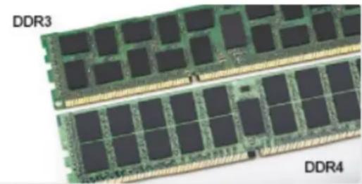
Key notch difference
The key notch on a DDR4 module is in a different location from the key notch on a DDR3 module. Both notches are on the insertion edge but the notch location on the DDR4 is slightly different, to prevent the module from being installed into an incompatible board or platform.
natural_image
Two rows of DDR3 and DDR4 memory chips with visible die structure (no text or symbols on the chips themselves)Figure 1. Notch difference
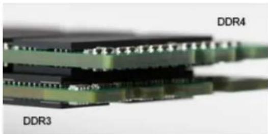
Increased thickness
DDR4 modules are slightly thicker than DDR3, to accommodate more signal layers.
natural_image
Close-up of a layered electronic component with labeled DDR3 and DDR4 (no additional text or symbols visible)Figure 2. Thickness difference
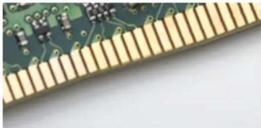
Curved edge
DDR4 modules feature a curved edge to help with insertion and alleviate stress on the PCB during memory installation.
natural_image
Close-up of a green circuit board with gold traces and small components (no visible text or symbols)Figure 3. Curved edge
Memory Errors
Memory errors on the system display the new ON-FLASH-FLASH or ON-FLASH-ON failure code. If all memory fails, the LCD does not turn on. Troubleshoot for possible memory failure by trying known good memory modules in the memory connectors on the bottom of the system or under the keyboard, as in some portable systems.
HDMI 1.4
This topic explains the HDMI 1.4 and its features along with the advantages.
HDMI (High-Definition Multimedia Interface) is an industry-supported, uncompressed, all-digital audio/video interface. HDMI provides an interface between any compatible digital audio/video source, such as a DVD player, or A/V receiver and a compatible digital audio and/or video monitor, such as a digital TV (DTV). The intended applications for HDMI TVs, and DVD players. The primary advantage is cable reduction and content protection provisions. HDMI supports standard, enhanced, or high-definition video, plus multichannel digital audio on a single cable.

NOTE: The HDMI 1.4 will provide 5.1 channel audio support.
HDMI 1.4 Features
- HDMI Ethernet Channel - Adds high-speed networking to an HDMI link, allowing users to take full advantage of their IP-enabled devices without a separate Ethernet cable
- Audio Return Channel - Allows an HDMI-connected TV with a built-in tuner to send audio data "upstream" to a surround audio system, eliminating the need for a separate audio cable
• 3D - Defines input/output protocols for major 3D video formats, paving the way for true 3D gaming and 3D home theater applications - Content Type - Real-time signaling of content types between display and source devices, enabling a TV to optimize picture settings based on content type
• Additional Color Spaces - Adds support for additional color models used in digital photography and computer graphics - 4K Support - Enables video resolutions far beyond 1080p, supporting next-generation displays that will rival the Digital Cinema systems used in many commercial movie theaters
• HDMI Micro Connector - A new, smaller connector for phones and other portable devices, supporting video resolutions up to 1080p
• Automotive Connection System - New cables and connectors for automotive video systems, designed to meet the unique demands of the motoring environment while delivering true HD quality
Advantages of HDMI
• Quality HDMI transfers uncompressed digital audio and video for the highest, crispest image quality.
- Low -cost HDMI provides the quality and functionality of a digital interface while also supporting uncompressed video formats in a simple, cost-effective manner
- Audio HDMI supports multiple audio formats from standard stereo to multichannel surround sound
- HDMI combines video and multichannel audio into a single cable, eliminating the cost, complexity, and confusion of multiple cables currently used in A/V systems
- HDMI supports communication between the video source (such as a DVD player) and the DTV, enabling new functionality
USB features
Universal Serial Bus, or USB, was introduced in 1996. It dramatically simplified the connection between host computers and peripheral devices like mice, keyboards, external drivers, and printers.
Let's take a quick look on the USB evolution referencing to the table below.
Table 1. USB evolution
| Type Data Transfer Rate Category Introduction Year | ||
| USB 2.0 480 Mbps High Speed 2000 | ||
| USB 3.0/USB 3.1 Gen 1.5 Gbps Super Speed 2010 | ||
| USB 3.1 Gen 2 10 Gbps Super Speed 2013 |
USB 3.0/USB 3.1 Gen 1 (SuperSpeed USB)
For years, the USB 2.0 has been firmly entrenched as the de facto interface standard in the PC world with about 6 billion devices sold, and yet the need for more speed grows by ever faster computing hardware and ever greater bandwidth demands. The USB 3.0/USB 3.1 Gen 1 finally has the answer to the consumers' demands with a theoretically 10 times faster than its predecessor. In a nutshell, USB 3.1 Gen 1 features are as follows:
• Higher transfer rates (up to 5 Gbps)
- Increased maximum bus power and increased device current draw to better accommodate power-hungry devices
- New power management features
• Full-duplex data transfers and support for new transfer types
- Backward USB 2.0 compatibility
- New connectors and cable
The topics below cover some of the most commonly asked questions regarding USB 3.0/USB 3.1 Gen 1.

Speed
Currently, there are 3 speed modes defined by the latest USB 3.0/USB 3.1 Gen 1 specification. They are Super-Speed, Hi-Speed and Full-Speed. The new SuperSpeed mode has a transfer rate of 4.8Gbps. While the specification retains Hi-Speed, and Full-Speed USB mode, commonly known as USB 2.0 and 1.1 respectively, the slower modes still operate at 480Mbps and 12Mbps respectively and are kept to maintain backward compatibility.
USB 3.0/USB 3.1 Gen 1 achieves the much higher performance by the technical changes below:
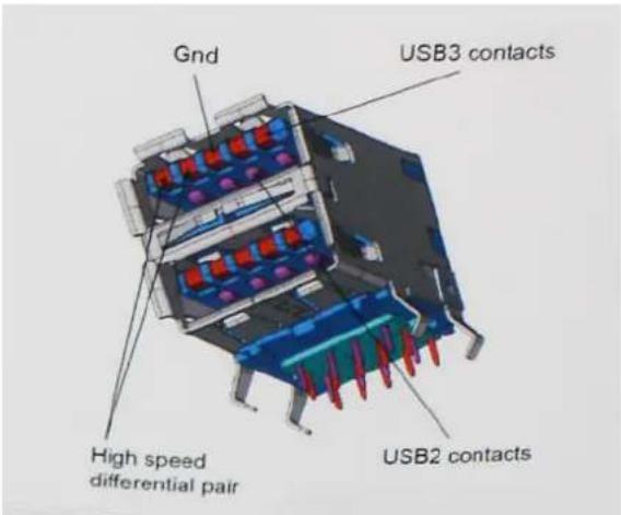
- An additional physical bus that is added in parallel with the existing USB 2.0 bus (refer to the picture below).
- USB 2.0 previously had four wires (power, ground, and a pair for differential data); USB 3.0/USB 3.1 Gen 1 adds four more for two pairs of differential signals (receive and transmit) for a combined total of eight connections in the connectors and cabling.
- USB 3.0/USB 3.1 Gen 1 utilizes the bidirectional data interface, rather than USB 2.0's half-duplex arrangement. This gives a 10-fold increase in theoretical bandwidth.
text_image
Gnd USB3 contacts High speed differential pair USB2 contactsWith today's ever increasing demands placed on data transfers with high-definition video content, terabyte storage devices, high megapixel count digital cameras etc., USB 2.0 may not be fast enough. Furthermore, no USB 2.0 connection could ever come close to the 480Mbps theoretical maximum throughput, making data transfer at around 320Mbps (40MB/s) — the actual real-world maximum. Similarly, USB 3.0/USB 3.1 Gen 1 connections will never achieve 4.8Gbps. We will likely see a real-world maximum rate of 400MB/s with overheads. At this speed, USB 3.0/USB 3.1 Gen 1 is a 10x improvement over USB 2.0.
Applications
USB 3.0/USB 3.1 Gen 1 opens up the laneways and provides more headroom for devices to deliver a better overall experience. Where USB video was barely tolerable previously (both from a maximum resolution, latency, and video compression perspective), it's easy to imagine that with 5-10 times the bandwidth available, USB video solutions should work that much better. Single-link DVI requires almost 2Gbps throughput. Where 480Mbps was limiting, 5Gbps is more than promising. With its promised 4.8Gbps speed, the standard will find its way into some products that previously weren't USB territory, like external RAID storage systems.
Listed below are some of the available SuperSpeed USB 3.0/USB 3.1 Gen 1 products:
- External Desktop USB 3.0/USB 3.1 Gen 1 Hard Drives
- Portable USB 3.0/USB 3.1 Gen 1 Hard Drives
• USB 3.0/USB 3.1 Gen 1 Drive Docks & Adapters - USB 3.0/USB 3.1 Gen 1 Flash Drives & Readers
- USB 3.0/USB 3.1 Gen 1 Solid-state Drives
- USB 3.0/USB 3.1 Gen 1 RAIDs
• Optical Media Drives - Multimedia Devices
- Networking
• USB 3.0/USB 3.1 Gen 1 Adapter Cards & Hubs
Compatibility
The good news is that USB 3.0/USB 3.1 Gen 1 has been carefully planned from the start to peacefully co-exist with USB 2.0. First of all, while USB 3.0/USB 3.1 Gen 1 specifies new physical connections and thus new cables to take advantage of the higher speed capability of the new protocol, the connector itself remains the same rectangular shape with the four USB 2.0 contacts in the exact same location as before. Five new connections to carry receive and transmitted data independently are present on USB 3.0/USB 3.1 Gen 1 cables and only come into contact when connected to a proper SuperSpeed USB connection.
Windows 8/10 will be bringing native support for USB 3.1 Gen 1 controllers. This is in contrast to previous versions of Windows, which continue to require separate drivers for USB 3.0/USB 3.1 Gen 1 controllers.
Microsoft announced that Windows 7 would have USB 3.1 Gen 1 support, perhaps not on its immediate release, but in a subsequent Service Pack or update. It is not out of the question to think that following a successful release of USB 3.0/USB 3.1 Gen 1 support in Windows 7, SuperSpeed support would trickle down to Vista. Microsoft has confirmed this by stating that most of their partners share the opinion that Vista should also support USB 3.0/USB 3.1 Gen 1.
Advantages of Displayport over USB Type-C
• Full DisplayPort audio/video (A/V) performance (up to 4K at 60Hz)
• SuperSpeed USB (USB 3.1) data
- Reversible plug orientation and cable direction
- Backwards compatibility to VGA, DVI with adaptors
• Supports HDMI 2.0a and is backwards compatible with previous versions
USB Type-C
USB Type-C is a new, tiny physical connector. The connector itself can support various exciting new USB standard like USB 3.1 and USB power delivery (USB PD).
Alternate Mode
USB Type-C is a new connector standard that's very small. It's about a third the size of an old USB Type-A plug. This is a single connector standard that every device should be able to use. USB Type-C ports can support a variety of different protocols using "alternate modes," which allows you to have adapters that can output HDMI, VGA, DisplayPort, or other types of connections from that single USB port
USB Power Delivery
The USB PD specification is also closely intertwined with USB Type-C. Currently, smartphones, tablets, and other mobile devices often use a USB connection to charge. A USB 2.0 connection provides up to 2.5 watts of power — that'll charge your phone, but that's about it. A laptop might require up to 60 watts, for example. The USB Power Delivery specification ups this power delivery to 100 watts. It's bidirectional, so a device can either send or receive power. And this power can be transferred at the same time the device is transmitting data across the connection.
This could spell the end of all those proprietary laptop charging cables, with everything charging via a standard USB connection. You could charge your laptop from one of those portable battery packs you charge your smartphones and other portable devices from today. You could plug your laptop into an external display connected to a power cable, and that external display would charge your laptop as you used it as an external display — all via the one little USB Type-C connection. To use this, the device and the cable have to support USB Power Delivery. Just having a USB Type-C connection doesn't necessarily mean they do.
USB Type-C and USB 3.1
USB 3.1 is a new USB standard. USB 3's theoretical bandwidth is 5 Gbps, while USB 3.1 Gen2 is 10Gbps. That's double the bandwidth, as fast as a first-generation Thunderbolt connector. USB Type-C isn't the same thing as USB 3.1. USB Type-C is just a connector shape, and the underlying technology could just be USB 2 or USB 3.0. In fact, Nokia's N1 Android tablet uses a USB Type-C connector, but underneath it's all USB 2.0 — not even USB 3.0. However, these technologies are closely related.
Disassembly and reassembly
Subscriber Identity Module(SIM) board
Removing the Subscriber Identification Module card

CAUTION: Removing the SIM card when the computer is on may cause data loss or damage the card. Ensure your computer is turned off or the network connections are disabled.
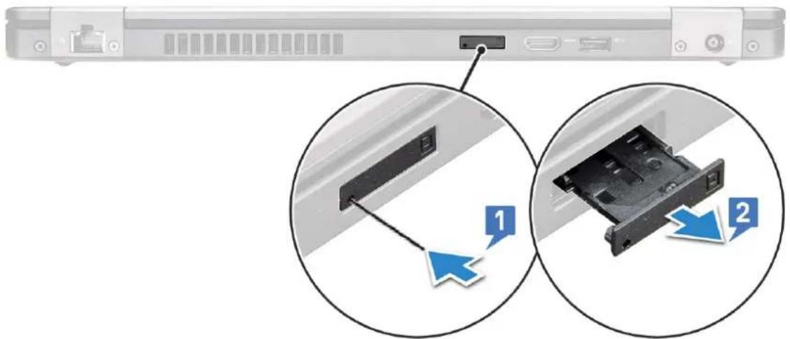
- Insert a paperclip or a SIM card removal tool into the pinhole on the SIM card tray [1].
- Pull the SIM card tray to remove it [2].
- Remove the SIM card from the SIM card tray.
- Push the SIM card tray into the slot until it clicks into place.
text_image
Diagram showing two views of a server rack with labeled components and directional arrows indicating connection or movement.Installing the Subscriber Identification Module card
- Insert a paperclip or a SIM card removal tool into the pinhole [1].
- Pull the SIM card tray to remove it [2].
- Place the SIM card on the SIM card tray.
- Push the SIM card tray into the slot until it clicks into place.
SD card—optional
SD card is an optional component. You will see a SD card only in systems shipped with a WWAN card.
Removing the SD card – WWAN models
- Follow the procedure Before working inside your computer
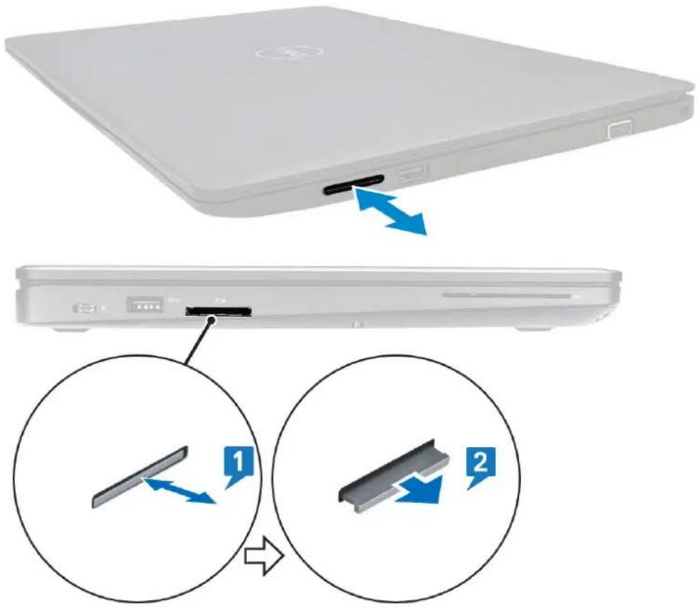
- Push the SD card so that the SD card pops out from its slot [1], and then remove it from the system [2].
text_image
Diagram showing device rear panel with blue arrows indicating movement, and two circular insets illustrating the process of a device's internal structure.Installing the SD card – WWAN models
- Push the SD card into its slot until the SD card gets secured with a click sound.
- Follow the procedure in After working inside your computer
Base cover
Removing the base cover
- Follow the procedure in Before working inside your computer.
- To remove the base cover:
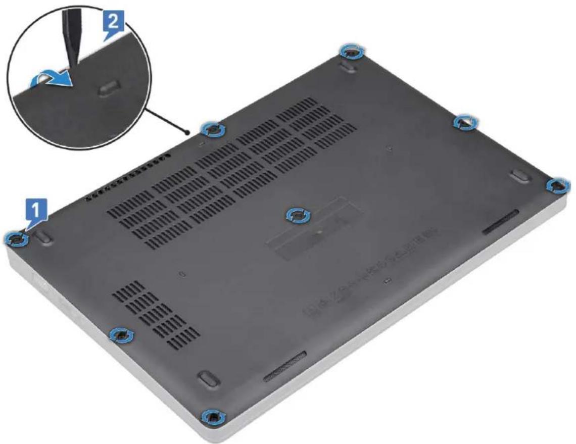
a. Loosen the 8 (M2.0x6) captive screws that secure the base cover to the system [1].
b. Pry the base cover from the recess at the top edge [2] and continue prying throughout the outer sides of the base cover in clockwise direction to release the base cover.

NOTE: Use a plastic scribe to pry the base cover from the edges.
text_image
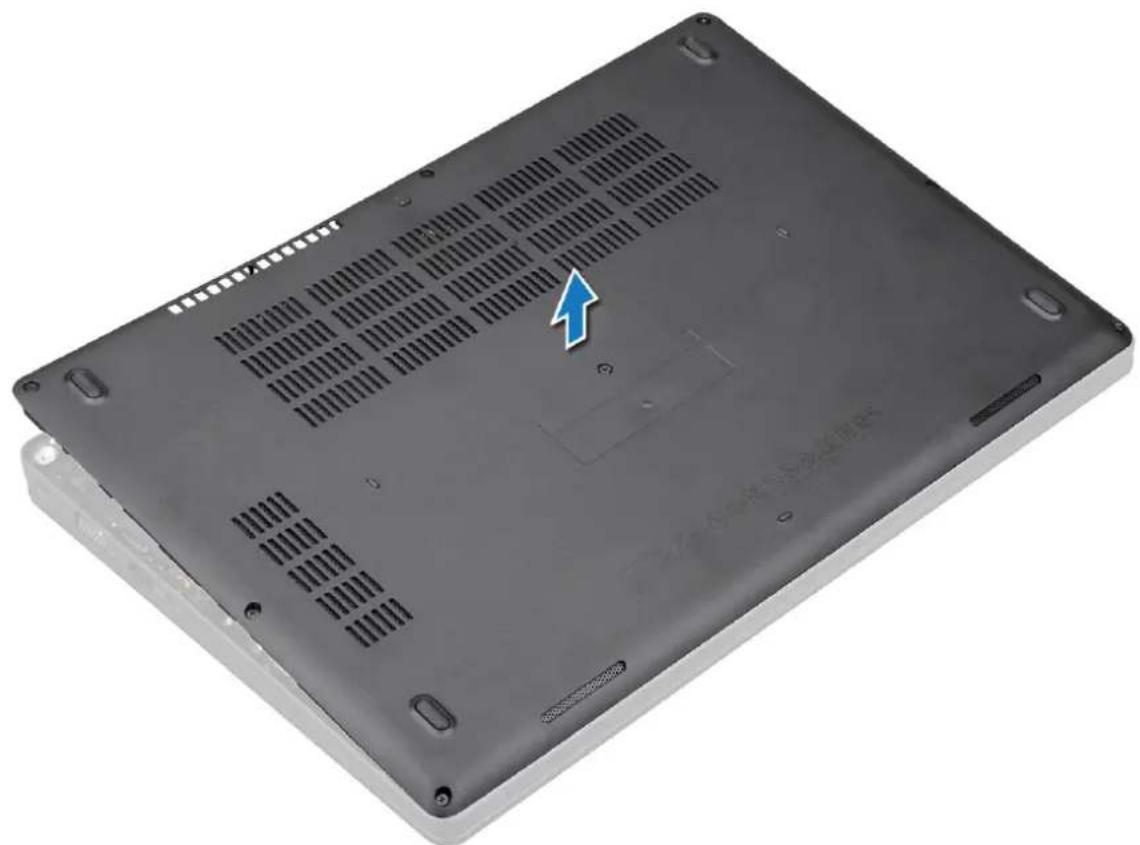
1 2 3c. Lift the base cover from the system.
natural_image
Back panel of a black laptop with ventilation grilles and mounting holes, showing no text or symbols on the cover itself.Installing the base cover
- Place the base cover to align with the screw holders on the system and press the sides of the base cover.
- Tighten the 8 (M2.0x6) captive screws to secure the base cover to the system.
- Follow the procedure in After working inside your computer.
Battery
Lithium-ion battery precautions

CAUTION:
• Exercise caution when handling Lithium-ion batteries.
- Discharge the battery as much as possible before removing it from the system. This can be done by disconnecting the AC adapter from the system to allow the battery to drain.
- Do not crush, drop, mutilate, or penetrate the battery with foreign objects.
- Do not expose the battery to high temperatures, or disassemble battery packs and cells.
- Do not apply pressure to the surface of the battery.
- Do not bend the battery.
- Do not use tools of any kind to pry on or against the battery.
- Ensure any screws during the servicing of this product are not lost or misplaced, to prevent accidental puncture or damage to the battery and other system components.
- If a battery gets stuck in a device as a result of swelling, do not try to free it as puncturing, bending, or crushing a Lithium-ion battery can be dangerous. In such an instance, contact for assistance and further instructions.
- If the battery gets stuck inside your computer as a result of swelling, do not try to release it as puncturing, bending, or crushing a lithium-ion battery can be dangerous. In such an instance, contact Dell technical support for assistance. See https://www.dell.com/support.
• Always purchase genuine batteries from https://www.dell.com or authorized Dell partners and resellers.
Removing the battery
- Follow the procedure in Before working inside your computer.
- Remove the base cover.
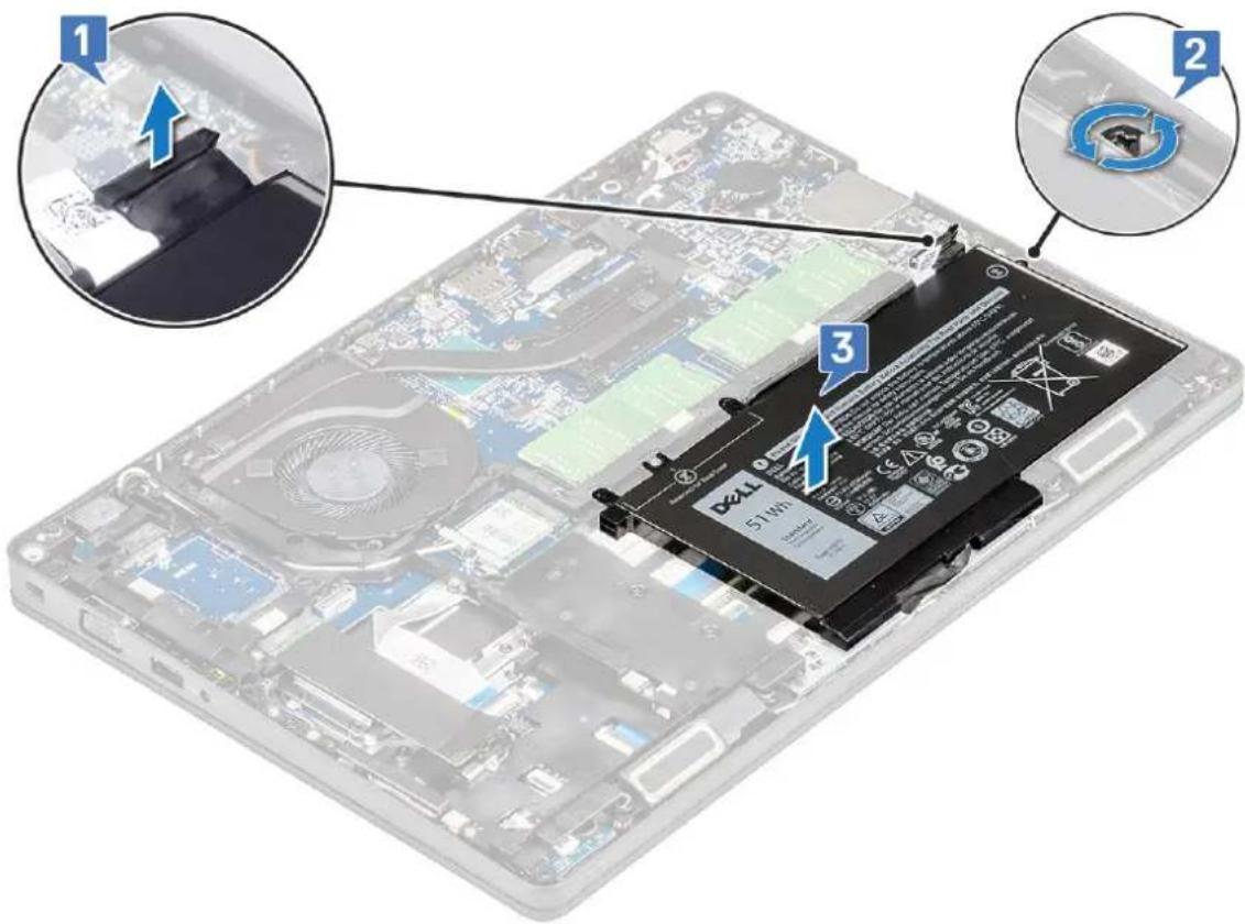
- To remove the battery:
a. Disconnect the battery cable from the connector on the system board [1] and unroute the cable from the routing channel.
b. Loosen the M2x6 captive screw that secures the battery to the system [2].
c. Lift the battery away from the system [3].
text_image
Laptop screen with battery pack and three highlighted components showing assembly stepsInstalling the battery
- Insert the battery into the slot on the system.
- Route the battery cable through the routing channel.
- Tighten the M2x6 captive screw to secure the battery to the system.
- Connect the battery cable to the connector on the system board.
- Install the base cover.
- Follow the procedure in After working inside your computer.
SSD card—optional
Removing the SSD card

NOTE: The following steps are applicable for SATA M.2 2280 and PCIe M.2 2280
- Follow the procedure in Before working inside your computer.
- Remove the :
a. base cover
b. battery
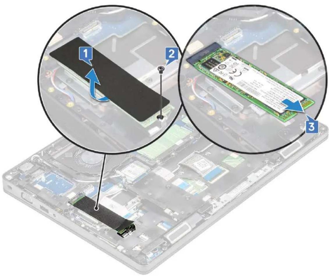
- To remove the Solid State Drive (SSD) card:
a. Peel the adhesive mylar shield that secures the SSD card [1].

NOTE: Remove the adhesive mylar carefully so that it can be reused on the replacement SSD.
b. Remove the M2x3 screw that secures the SSD to the system [2].
c. Slide and lift the SSD from the system [3].
text_image
Diagram showing three views of a computer RAM module with labeled components and annotations in ChineseInstalling the SSD card
NOTE: The following procedure applies for SATA M.2 2280 and PCIe M.2 2280
- Insert the SSD card into the connector on the system.
- Replace the M2*3 screw that secures the SSD card to the system.
- Place the Mylar shield over the SSD.
- Install the :
a. battery
b. base cover
- Follow the procedure in After working inside your computer.
SSD frame
Removing the SSD frame
- Follow the procedure in Before working inside your computer.
- Remove the:
a. base cover
b. battery
c. SSD card
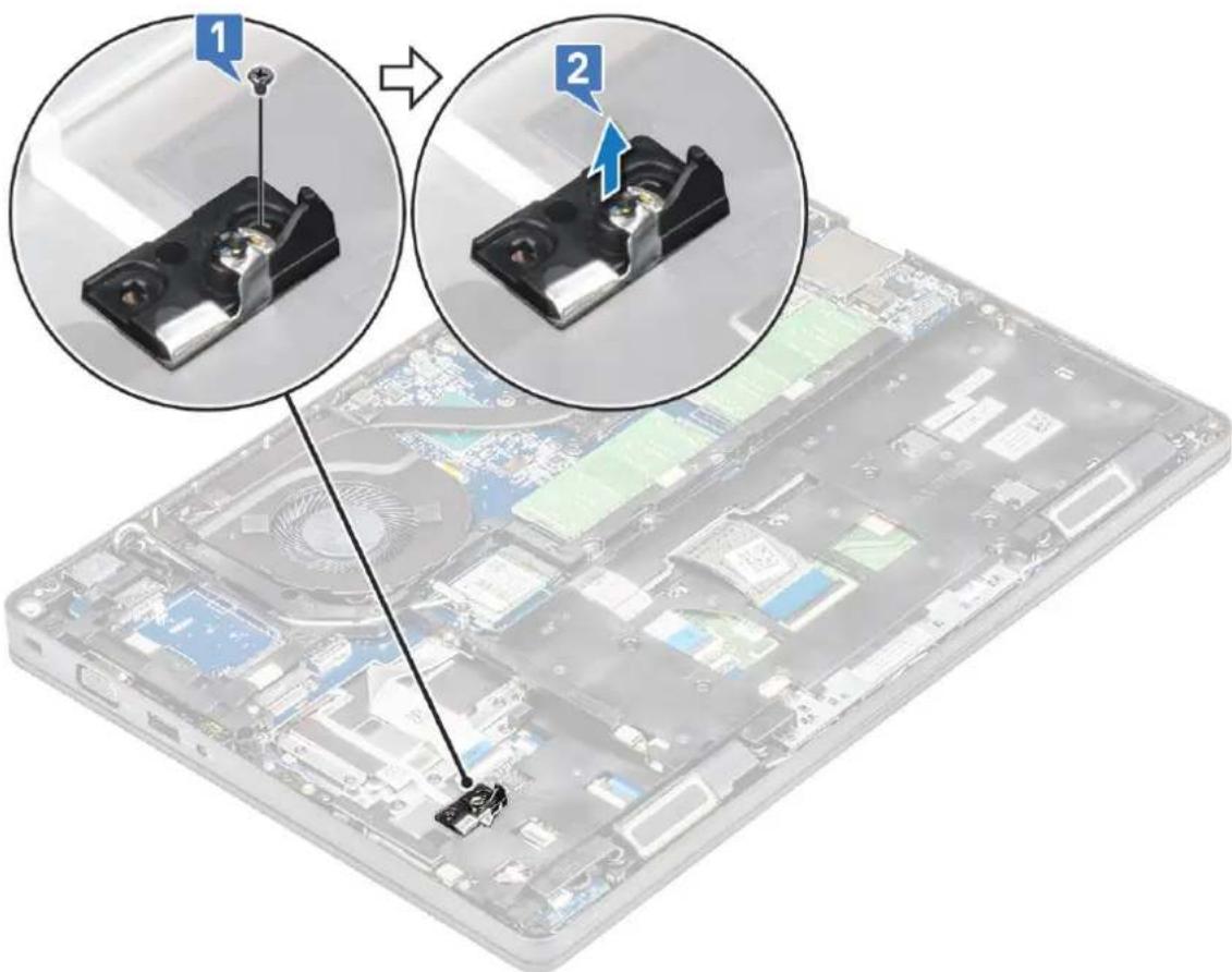
- To remove the SSD frame:
a. Remove the M2x3 screw that secures the SSD frame to the system [1].
b. Lift the SSD frame from the system [2].
text_image
Diagram showing two views of a computer case with labeled components, including a close-up of the main component and a magnified view of its internal structure.Installing the SSD frame
- Place the SSD frame into the slot in the system.
- Replace the M2x3 screw that secures the SSD frame to the system.
- Install the:
a. SSD card
b. battery
c. base cover
- Follow the procedure in After working inside your computer.
Hard drive
Removing hard drive
- Follow the procedure in Before working inside your computer.
- Remove the :
a. base cover
b. battery
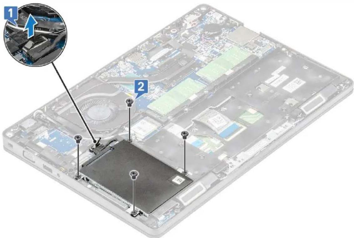
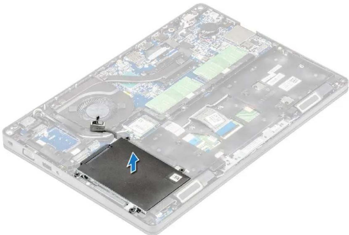
- To remove the hard drive:
a. Disconnect the hard drive cable from the connector on the system board [1].
b. Remove the four (M2 x 2.7) screws that secure the hard drive to the system [2].
text_image
Laptop screen with labeled components and a magnified inset showing a car engine interior viewc. Lift the hard drive from the system.
natural_image
Illustration of a laptop's internal components showing CPU socket and ventilation system (no text or symbols)Installing hard drive
- Insert the hard drive into the slot on the system.
- Replace the four (M2 x 2.7) screws to secure the hard drive to the system.
-
Connect the hard drive cable to the connector on the system board.
-
Install the :
a. battery
b. base cover
- Follow the procedures in After working inside your system.
Coin-cell battery
Removing the coin cell battery
- Follow the procedure in Before working inside your computer.
- Remove the :
a. base cover
b. battery
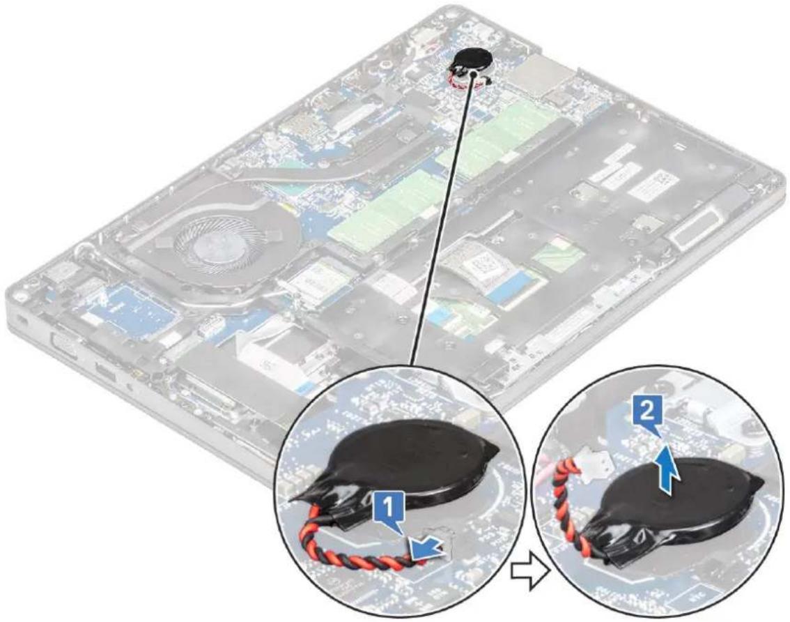
- To remove the coin cell battery:
a. Disconnect the coin cell battery cable from the connector on the system board [1].
b. Lift the coin cell battery to release from the adhesive and lift it away from the system board [2].
text_image
Diagram showing a device with a sensor connected to a cable, with two views of the cable being inserted into a circuit board.Installing coin cell battery
- Affix the coin cell battery on the system board.
- Connect the coin cell battery cable to the connector on the system board.
- Install the :
a. battery
b. base cover
- Follow the procedure in After working inside your computer.
WLAN card
Removing WLAN card
- Follow the procedure in Before working inside your computer.
- Remove the :
a. base cover
b. battery
- To remove the WLAN card:
a. Remove the M2x3 screw that secures the WLAN card bracket to the system [1].
b. Remove the WLAN card bracket that secures the WLAN antenna cables [2].
c. Disconnect the WLAN antenna cables from the connectors on the WLAN card [3].
d. Lift the WLAN card away the connector as shown in the figure [4].

CAUTION: There is an adhesive pad on the system board or chassis frame which helps secure the wireless card in place. When removing the wireless card from the system, make sure the adhesive pad stays on the system board/chassis frame during the prying process. If the adhesive pad is removed from the system along with the wireless card, adhere it back to the system.

text_image
Diagram showing four steps of assembling a device into a circuit board, with numbered annotations indicating component identification.Installing WLAN card
- Insert the WLAN card into the connector on the system board.
- Connect the WLAN antenna cables to the connectors on the WLAN card.
- Place the WLAN card bracket to secure the WLAN cables.
- Replace the M2x3 screw to secure the WLAN card to the system.
- Install the :
a. battery
b. base cover
- Follow the procedure in After working inside your computer.
WWAN card – optional
This is optional as the system might not ship with WWAN card.
Installing the WWAN card
- Insert the WWAN card into the slot on the system.
- Connect the WWAN antenna cables to the connectors on the WWAN card.
- Replace the screw (M2X3) to secure the WWAN card to the computer.
- Install the :
a. battery
b. base cover
- Follow the procedure in After working inside your computer.
Removing the WWAN card
- Follow the procedure in Before working inside your computer.
- Remove the :
a. base cover
b. battery
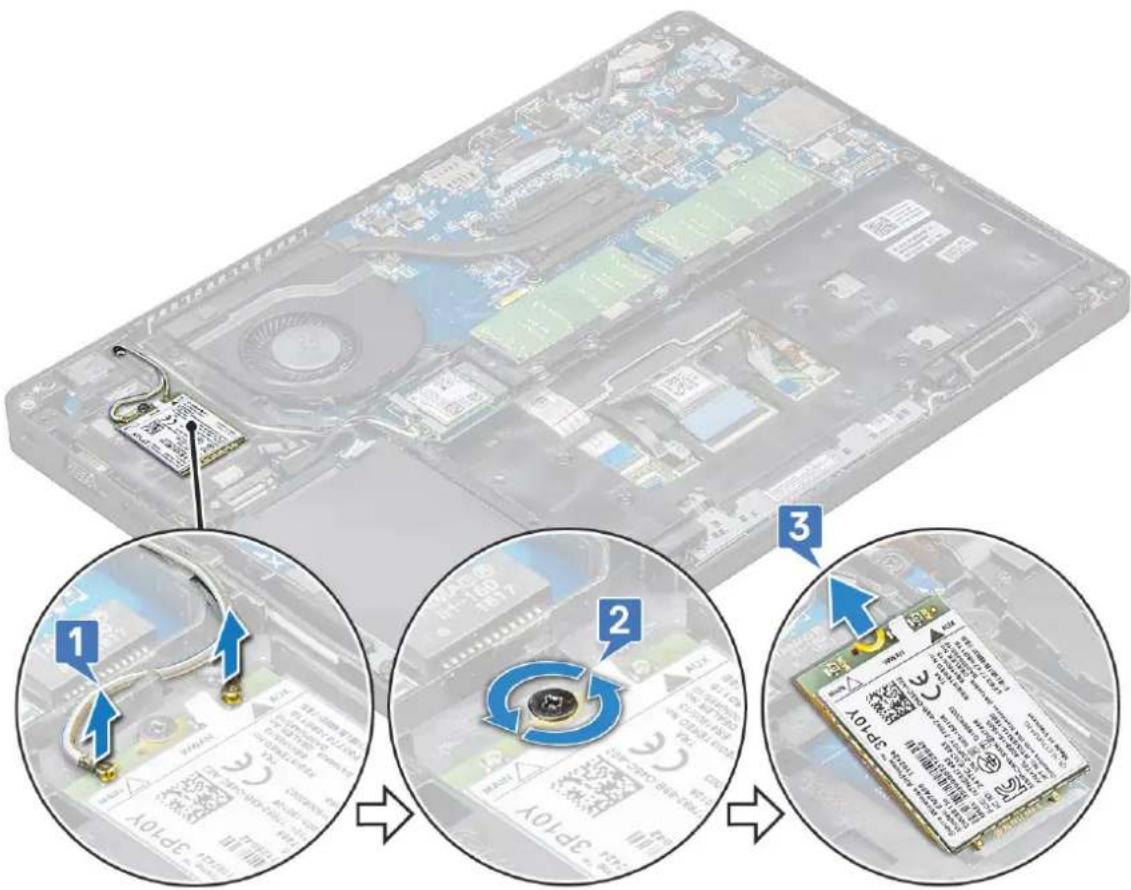
- To remove the WWAN card:
a. Disconnect the WWAN antenna cables from the connectors on the WWAN card [1].
b. Remove the M2x3 screw that secures the WWAN card to the system [2]
c. Slide and lift the WWAN card from the system [3].
text_image
Diagram illustrating the step-by-step installation of an electronic device, showing cable connection and chip positioning with labeled steps 1, 2, and 3.Memory modules
Removing the memory module
- Follow the procedure in Before working inside your computer.
- Remove the :
a. base cover
b. battery
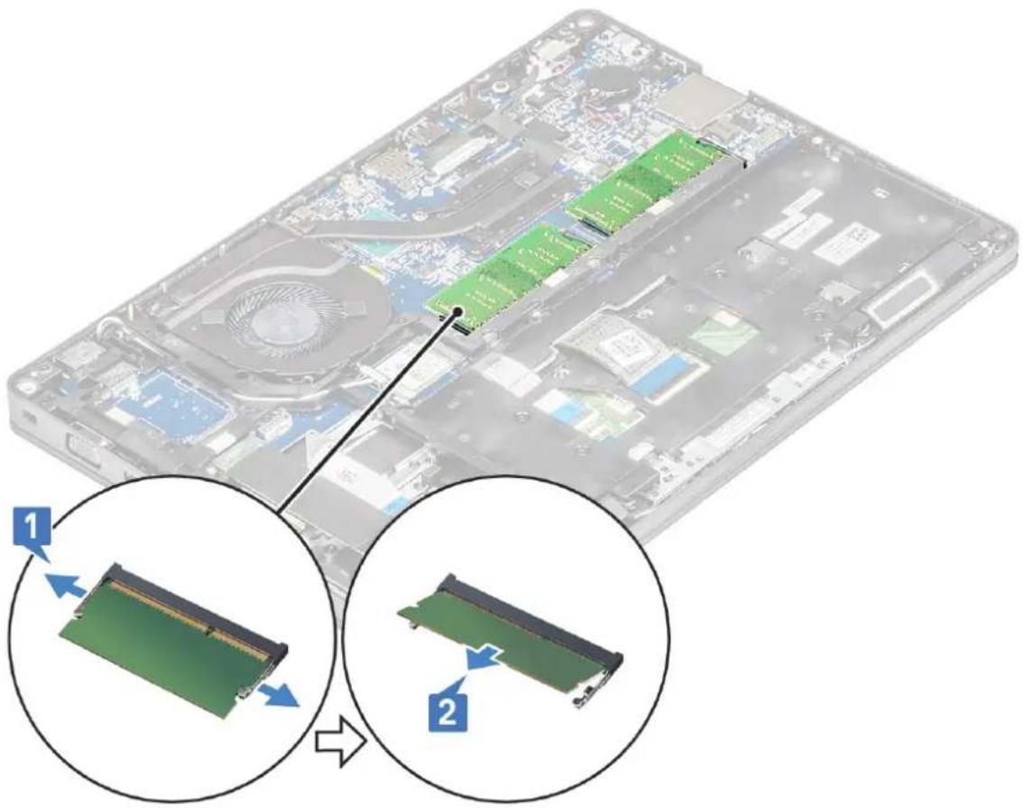
- To remove the memory module:
a. Pry the clips securing the memory module until the memory module pops-up [1].
b. Lift the memory module from the connector [2].
natural_image
Diagram showing two views of a computer chassis with internal RAM slots and a close-up of the internal RAM module (no text or symbols present)Installing the memory module
- Insert the memory module into the memory connector at a 30 degree angle until the contacts are fully seated into the slot. Then, press the module until the clips secure the memory module.
- Install the :
a. battery
b. base cover
- Follow the procedure in After working inside your computer.
Keyboard lattice and Keyboard
Removing keyboard lattice
- Follow the procedure in Before working inside your computer.
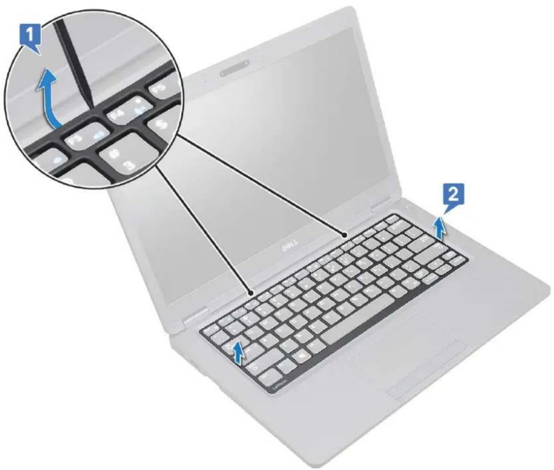
- Pry the keyboard lattice from one of the recess points [1] and continue prying the sides in clockwise or anticlockwise direction, and then lift the keyboard lattice from the system [2]
text_image
Laptop keyboard diagram with labeled parts and a magnified inset showing the keyboard's rotation direction.Installing keyboard lattice
- Place the keyboard lattice on the keyboard and press along the edges and in between the rows of keys until the lattice clicks in place.
- Follow the procedure in After working inside your computer.
Removing the keyboard
- Follow the procedure in Before working inside your computer.
- Remove the:
a. base cover
b. battery
c. keyboard lattice
- To remove the keyboard:
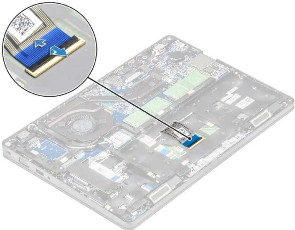
a. Lift the latch and disconnect the keyboard cable from the connector on the system.
b. Lift the latch and disconnect the keyboard backlight cable from the connector on the system [2].

NOTE: This step is applicable only for models that support keyboard backlight option. Number of cables to disconnect is based on the keyboard type.
natural_image
Transparent computer case with internal circuitry and a magnified inset showing a chip structure (no text or symbols visible)c. Turn over the system and open the laptop in front view mode.
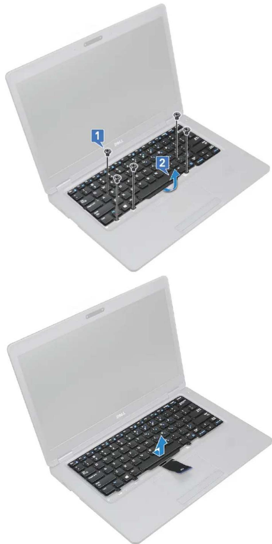
d. Remove the five (M2x2.5) screws that secure the keyboard to the system [1].
e. Flip the keyboard from the bottom and lift it from the system along with the keyboard cable and the keyboard back light cable [2].
WARNING: Gently pull the keyboard cable and the keyboard back light cable routed beneath the chassis frame to avoid damaging the cables.
text_image
Laptop keyboard diagram showing three states of change: open, with keys labeled 1 and 2, and closed, with a blue arrow indicating the change.Installing the keyboard
- Hold the keyboard and route the keyboard cable and the keyboard backlight cables through the palmrest in the system.
- Align the keyboard with the screw holders on the system.
- Replace the screws to secure the keyboard to the system.
- Turn the system over and connect the keyboard cable and the keyboard backlight cable to the connector in the system.

NOTE: When reinstalling the chassis frame ensure the keyboard cables are NOT under the lattice, but run through the opening in the frame before connecting them to system board.
- Install the:
a. keyboard lattice
b. battery
c. base cover
- Follow the procedure in After working inside your computer.
Heat sink
Removing the heat sink

NOTE: This procedure is only for the UMA model.
- Follow the procedure in Before working inside your computer.
- Remove the :
a. base cover
b. battery
- To remove the heat sink :
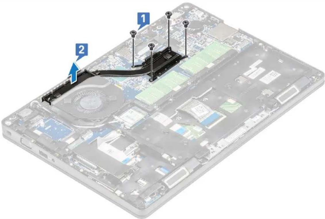
a. Remove the four (M2x3) screws that secure the heat sink on the system board [1].

NOTE:
- Remove the heat sink screws in sequential order as indicated on the heat-sink.
b. Lift the heat sink from the system [2].
text_image
Labeled diagram of a computer motherboard showing two components with numbered annotationsInstalling the heat sink

NOTE: This procedure is only for the UMA model.
- Place the heat sink on the system board.
- Replace the four (M2x3) screws that secure the heat sink on the system board.

NOTE:
- Replace the heat sink screws in sequential order as indicated on the heat-sink.
- Install the :
a. battery
b. base cover
- Follow the procedure in After working inside your computer.
System fan
Removing the system fan

NOTE: This procedure is only for the UMA model
- Follow the procedure in Before working inside your computer.
- Remove the:
a. base cover
b. battery
c. hard drive
d. SSD card
e. SSD frame
f. WLAN card
g. WWAN card (optional)
h. chassis frame
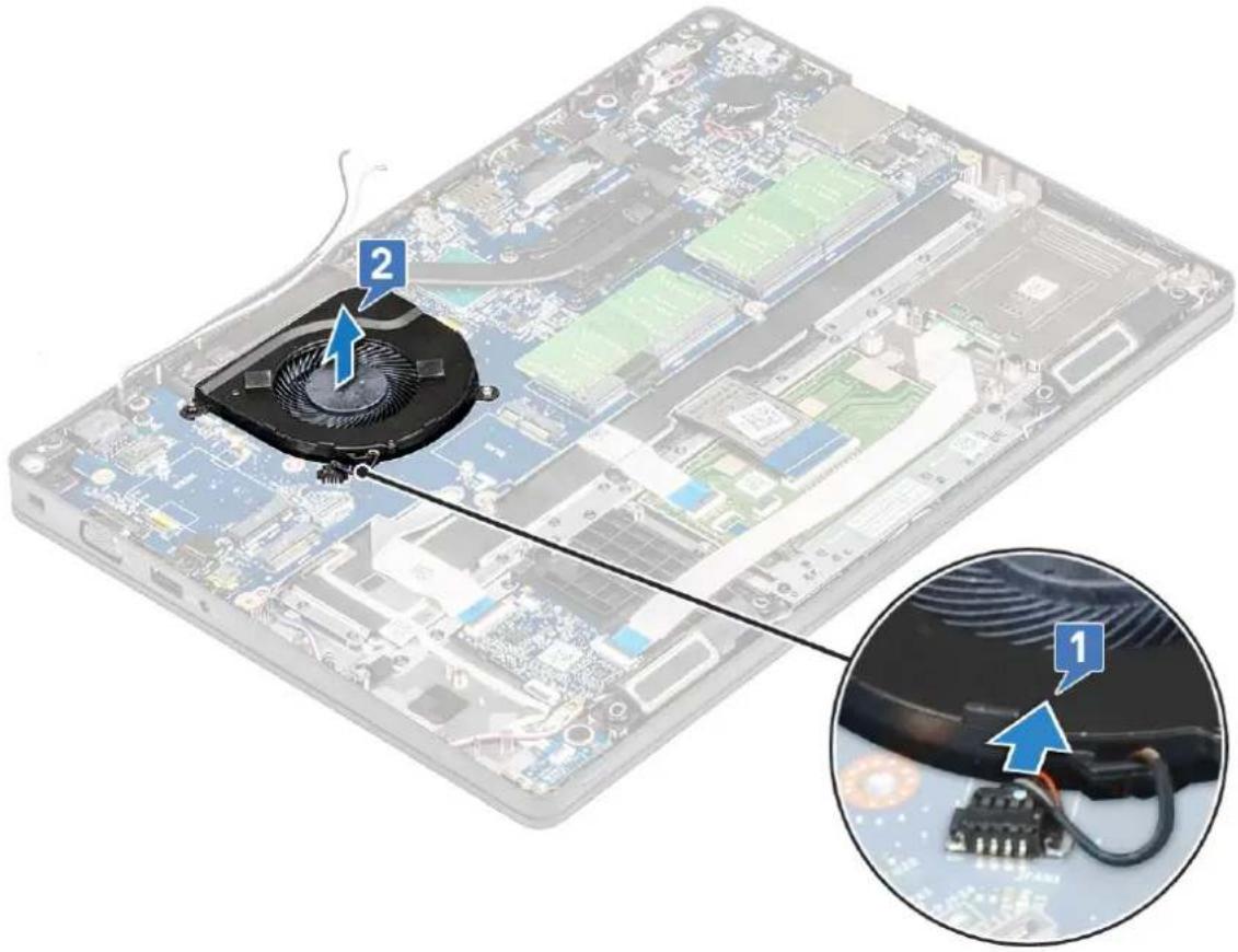
- To remove the system fan:
a. Disconnect the system fan cable from the connector on the system board [1].
b. Lift the system fan away from the computer [2].
text_image
Diagram showing a device with a fan and cable, labeled with numbered annotations pointing to the components.Installing the system fan

NOTE: This procedure is only for the UMA model
- Place the system fan into the slot on the computer.
- Connect the system fan cable to the connector on the system board.
- Install the:
a. chassis frame
b. WWAN card (optional)
c. WLAN card
d. SSD frame
e. SSD card
f. hard drive
g. battery
h. base cover
- Follow the procedure in After working inside your computer.
Power connector port
Removing the power connector port
- Follow the procedure in Before working inside your computer.
- Remove the :
a. base cover
b. battery
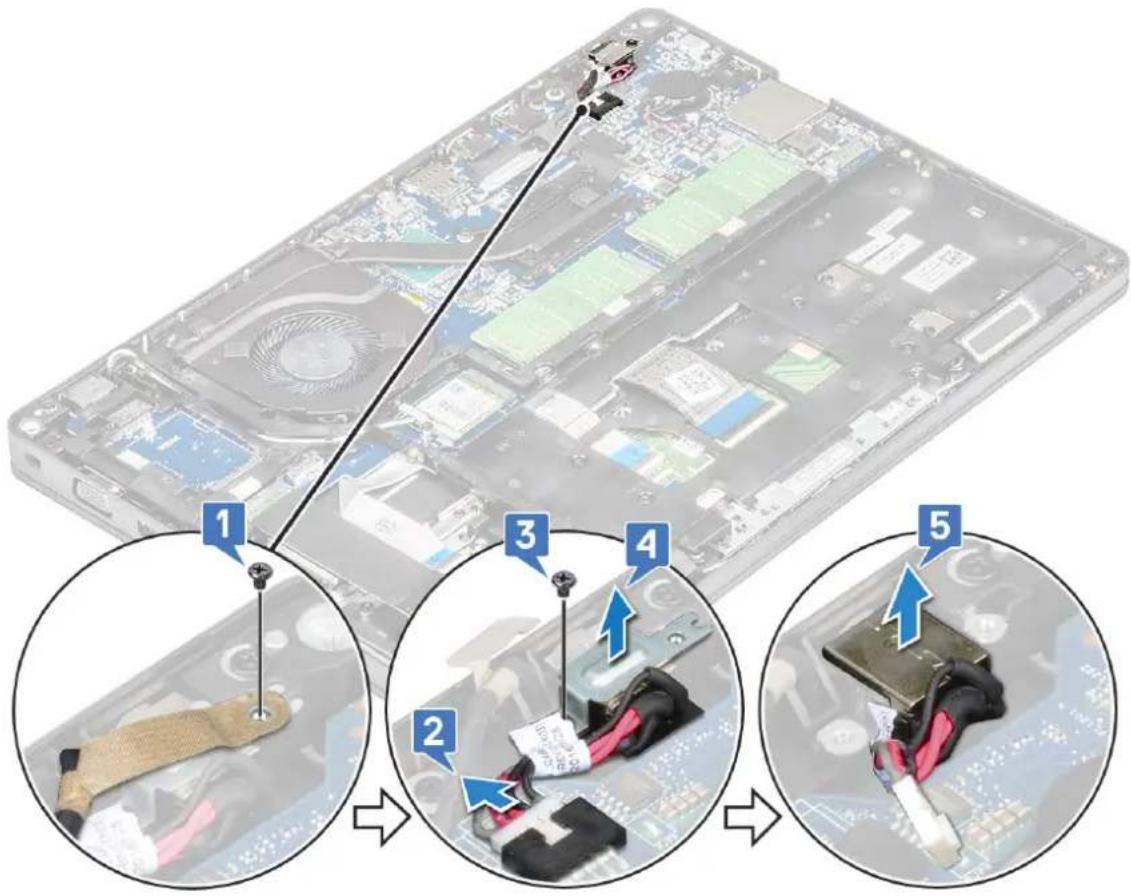
- To remove the power connector port:
a. Remove the M2x3 screw that secures the adhesive tape of the display cable to the power connector bracket [1], and peel off the adhesive tape.
b. Disconnect the power connector cable from the connector on the system board [2].
c. Remove the M2x3 screw to release the power connector bracket that secures the power connector port to your system [3].
d. Remove the power connector bracket from the system [4].
e. Pull the power connector port, and lift it from the system [5].
text_image
Diagram showing a device with labeled parts and steps, including cable installation and assembly stepsInstalling power connector port
- Align the power connector port along the grooves on the slot and push it down.
- Place the metal bracket on the power connector port.
- Replace the M2x3 screw that secures one end of the power connector bracket to the power connector port.
- Connect the power connector cable to the connector on the system board.
- Affix the adhesive tape of the display cable to the power connector bracket and replace the M2x3 screw to secure another end of the power connector bracket.
- Install the :
a. battery
b. base cover
- Follow the procedure in After working inside your computer.
Chassis frame
Removing the chassis frame
-
Follow the procedure in Before working inside your computer.
-
Remove the:
a. base cover
b. battery
c. hard drive
d. SSD card
e. SSD frame
f. WLAN card
g. WWAN card (optional)

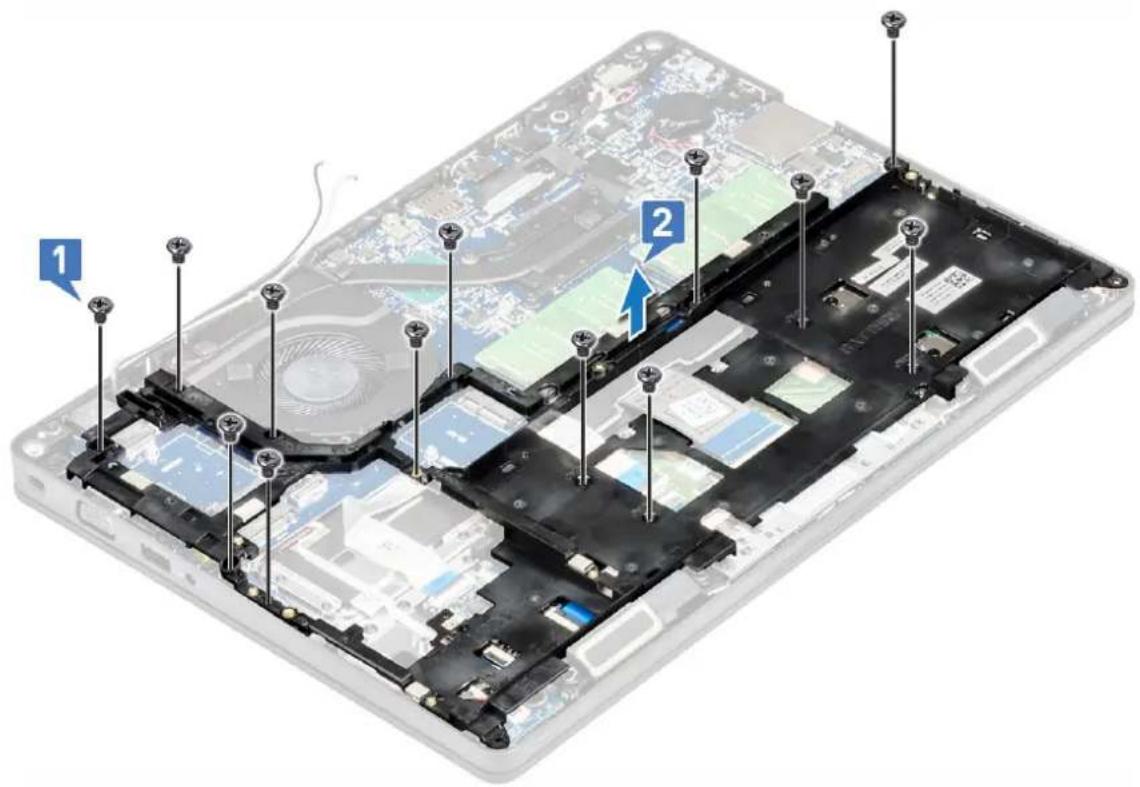
NOTE: There are two different screw sizes for chassis frame: M2x5 8ea and M2x3 5ea
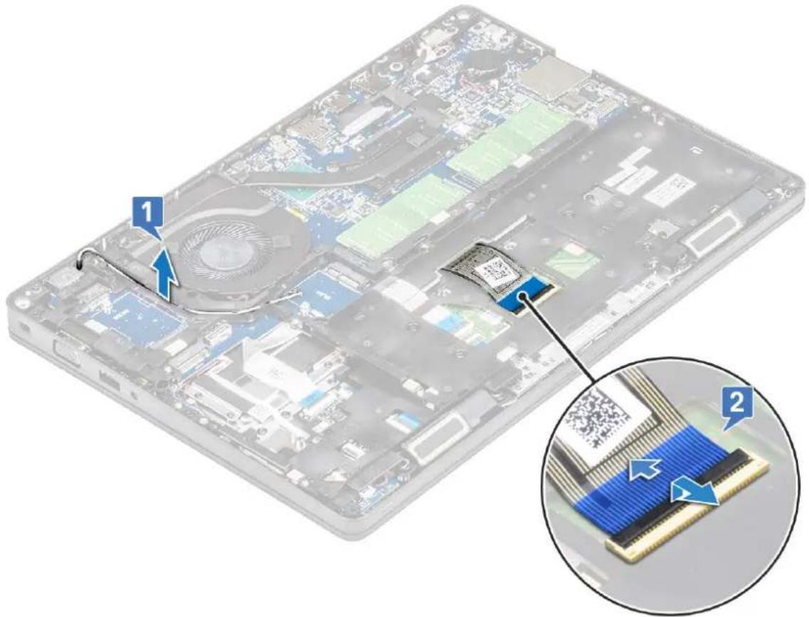
- To release the chassis frame:
a. Unroute the WLAN and WWAN cables from the routing channels [1].
b. Lift the latch and disconnect the keyboard backlight cable and the keyboard cable from their connectors [2] on the system.

NOTE: There may be more than one cable to disconnect based on the keyboard type.
text_image
Diagram showing a device with labeled components and an inset close-up of its internal structure, likely illustrating a hardware or circuit board assembly.- To remove the chassis frame:
a. Remove the five (M2x3) screws and eight (M2x5) screws that secure the chassis frame to the system [1].
b. Lift the chassis frame from the system [2].
text_image
Laptop interior diagram with numbered annotations pointing to structural componentsInstalling the chassis frame
- Place the chassis frame into the slot on the system.

NOTE: Gently pull the keyboard cable and keyboard back light cables through the spacing in the chassis frame before placing the chassis frame in the slot on the system.
- Replace the five (M2x3) screws and eight (M2x5) screws to secure the chassis frame to the system.
- Connect the keyboard cable and the keyboard backlight cable to their connectors on the system.

NOTE: There may be more than one cable to connect based on keyboard types.
- Route the WLAN and WWAN (optional) cables through the routing channels.
- Install the:
a. WWAN card (optional)
b. WLAN card
c. SSD frame
d. SSD card
e. hard drive
f. battery
g. base cover
- Follow the procedure in After working inside your system.
LED board
Removing LED board
- Follow the procedure in Before working inside your computer.
- Remove the .
a. base cover
b. battery
c. hard drive
d. SSD card
e. SSD frame
f. WLAN card
g. WWAN card (optional)
h. chassis frame
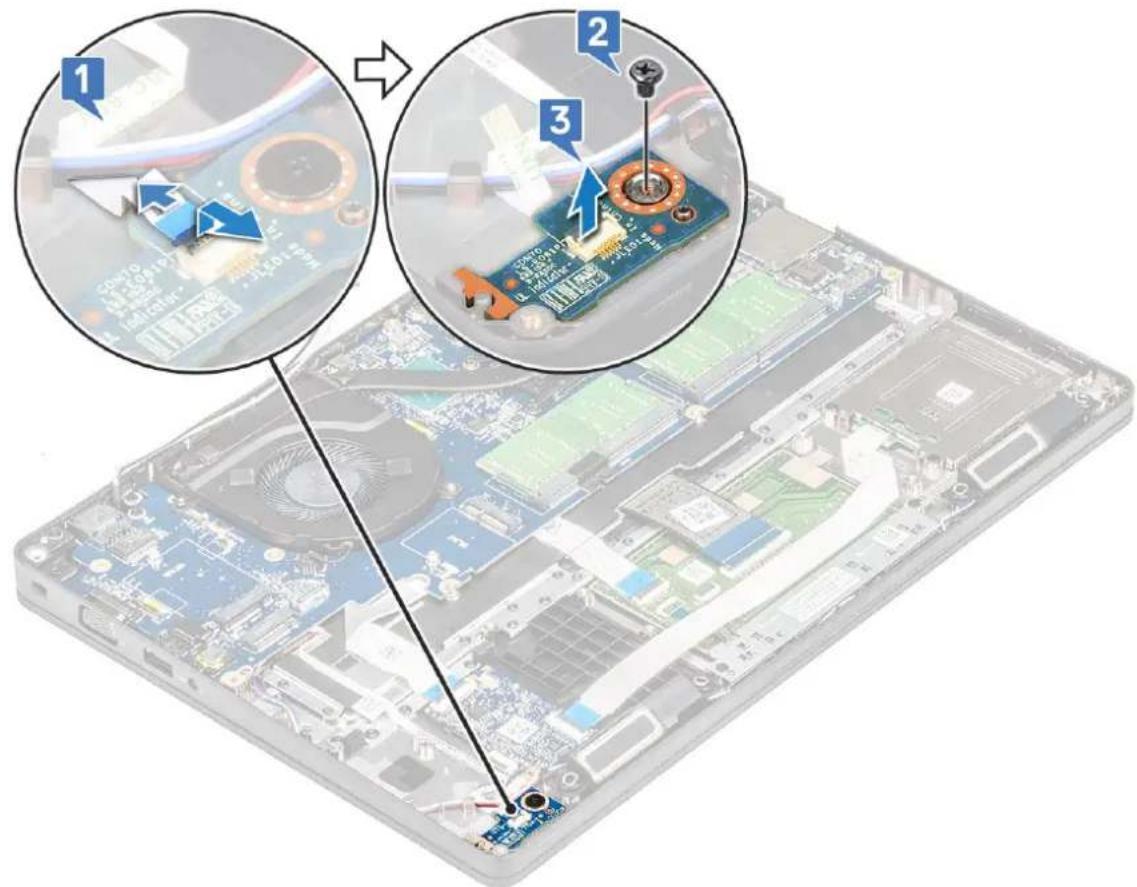
- To remove the LED board:
a. Lift the latch and remove the LED cable connected to the connector on the LED board [1]
b. Remove the (M2.0x2.0) screw that secures the LED board to the system [2].
c. Lift the LED board from the connector [3].
text_image
Diagram showing three steps of assembling a laptop motherboard with labeled components and annotations in Chinese.Installing LED board
- Place the LED board in its slot on the system.
- Replace the M2.0x2.0 screw to secure the LED board to the system.
- Connect the LED cable to its connector on the LED board.
- Install the:
a. chassis frame
b. WWAN card (optional)
c. WLAN card
d. SSD frame
e. SSD card
f. hard drive
g. battery
h. base cover
- Follow the procedure in After working inside your computer.
SmartCard module
Removing smart card reader board
- Follow the procedure in Before working inside your computer.
- Remove the:
a. base cover
b. battery
c. hard drive
d. SSD card
e. SSD frame
f. WLAN card
g. WWAN card (optional)
h. chassis frame
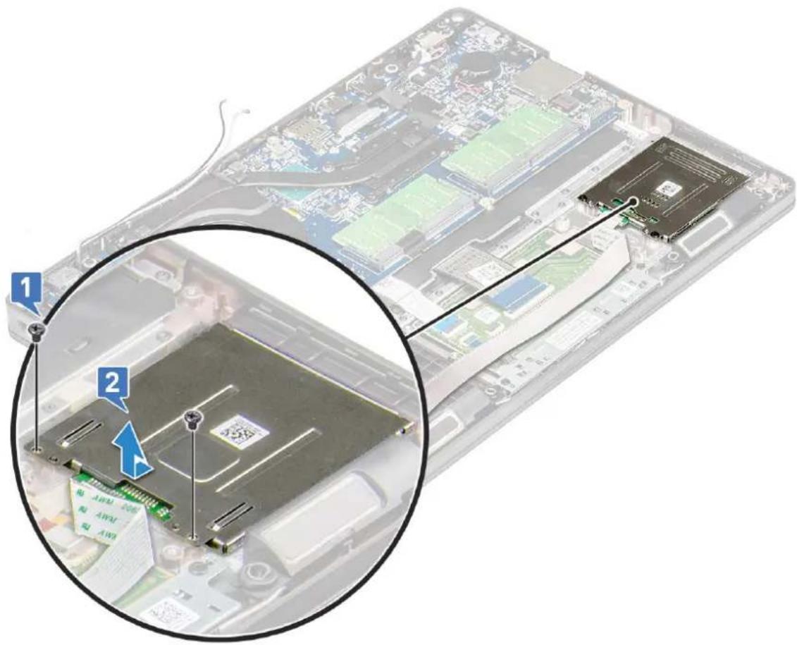
- To release the smart card reader board:
- To remove the smart card reader board:
a. Remove the 2 (M2x3) screws that secure the smart card reader board to the palmrest [1].
b. Slide and lift the smart card reader from the slot in the system [2].
text_image
Diagram of an open computer case with labeled components, showing a close-up view of the internal CPU and memory drive.Installing smart card reader board
- Insert the smart card reader board to align with the tabs on the chassis.
- Replace the 2 (M2x3) screws to secure the smart card reader board to the system.
-
Affix the smart card reader board cable and connect the cable to the connector.
-
Install the:
a. chassis frame
b. WWAN card (optional)
c. WLAN card
d. SSD frame
e. SSD card
f. hard drive
g. battery
h. base cover
- Follow the procedure in After working inside your computer.
Touchpad panel
Removing the touchpad
-
Follow the procedure in Before working inside your computer.
-
Remove the:
a. base cover
b. battery
c. SSD card
d. SSD frame
e. WLAN card
f. WWAN card
g. chassis frame
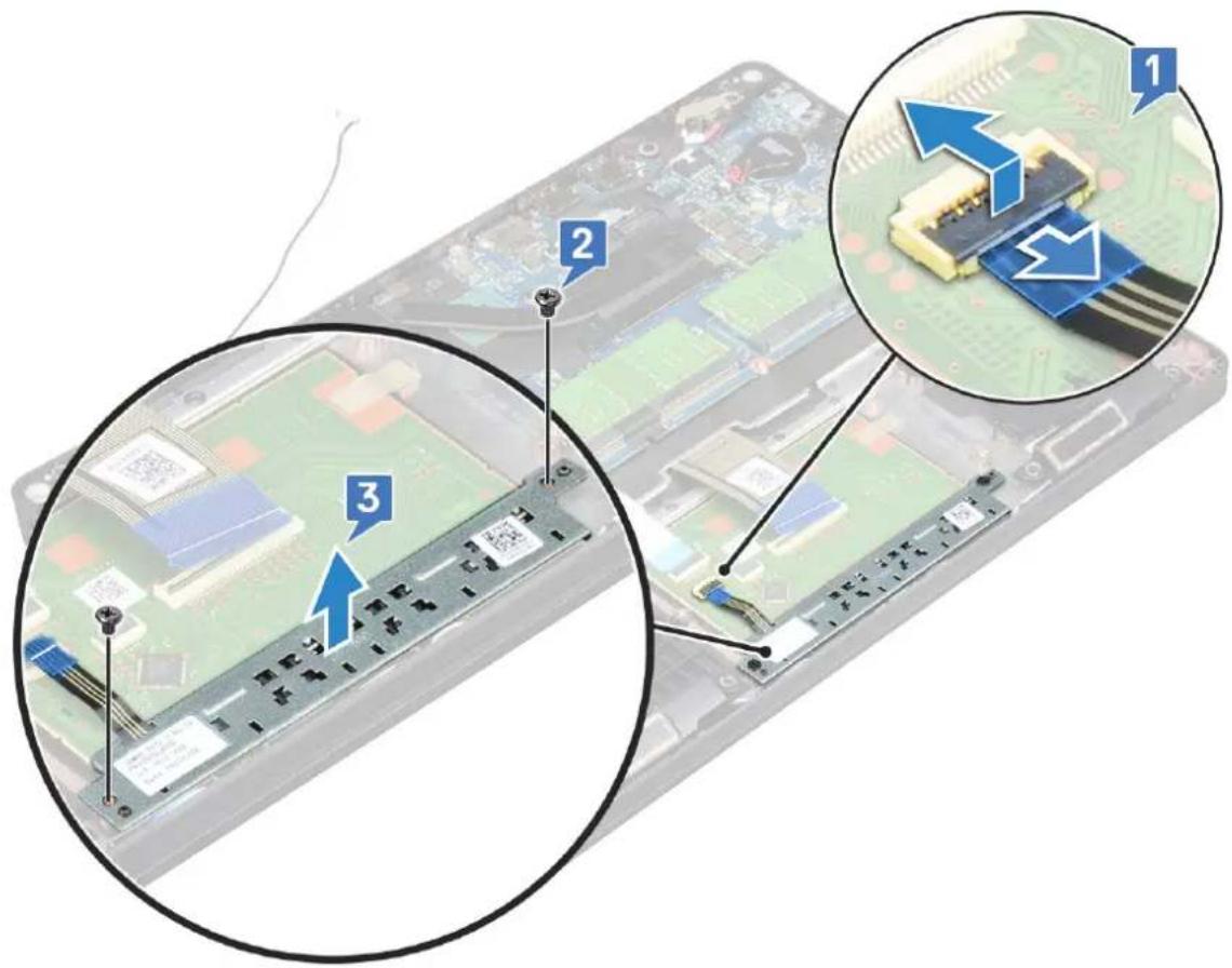
- To remove the touchpad panel:
a. Disconnect the touchpad panel cable from the connector on the system board [1].
b. Remove the two M2x3 screws that secure the touchpad panel to the system. [2].
c. Lift the touchpad panel from the system [3].
text_image
Labeled diagram of an electronic device showing internal components and a close-up view with numbered annotations.Installing touchpad panel
- Place the touchpad panel into its slot on the chassis.
- Tighten the two screws to secure the touchpad panel to your system.
- Connect the touchpad panel cable to the connector on the system board.
- Install the:
a. chassis frame
b. SSD frame
c. SSD card
d. WWAN
e. WLAN card
f. battery
g. base cover
- Follow the procedure in After working inside your computer.
System board
Removing system board
- Follow the procedure in Before working inside your computer.
- Remove the:
a. SIM card
b. base cover
c. battery
d. memory module
e. hard drive
f. SSD card
g. SSD frame
h. WLAN card
i. WWAN card (optional)
j. keyboard lattice
k. keyboard
I. heat sink
m. chassis frame
n. system fan
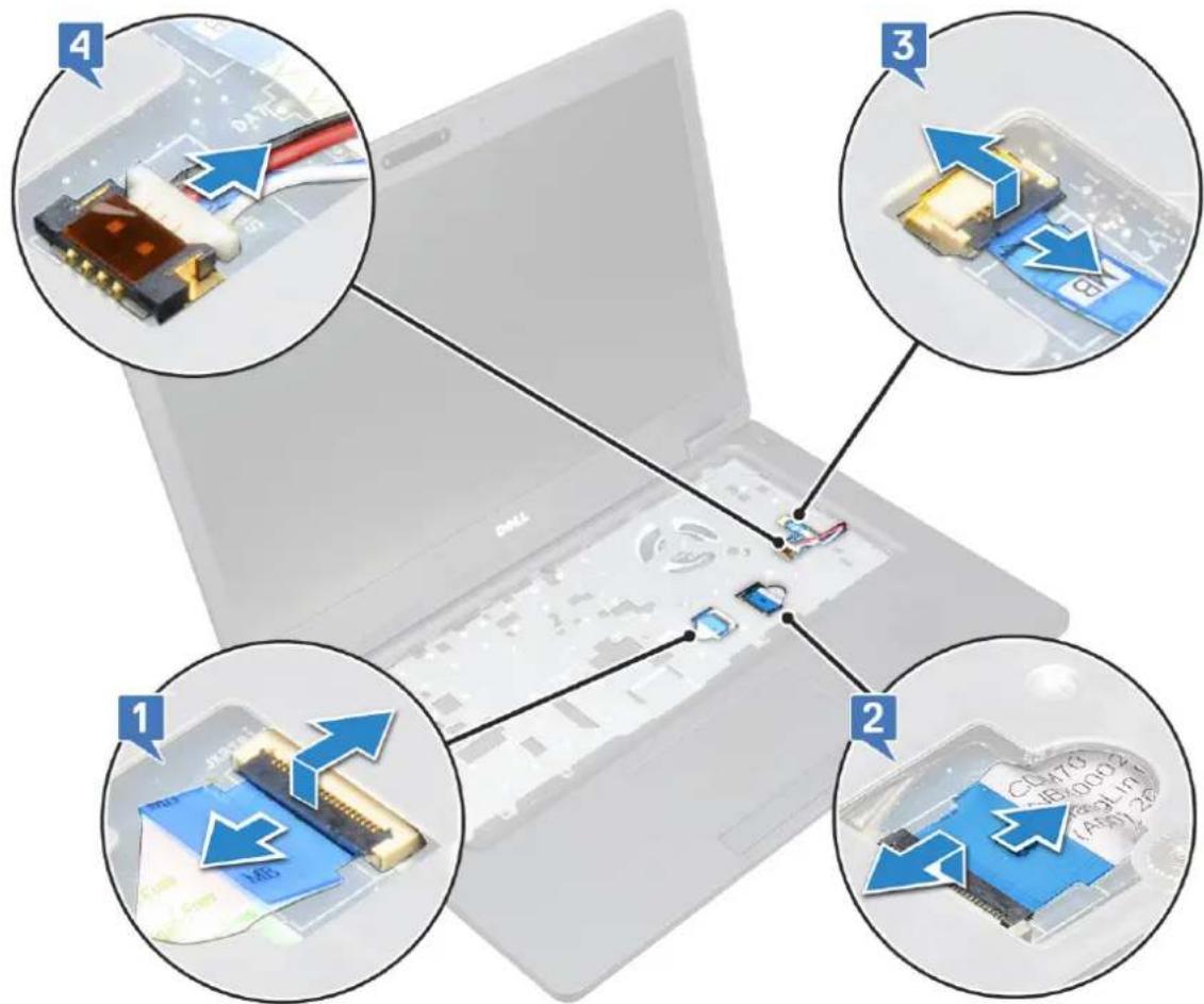
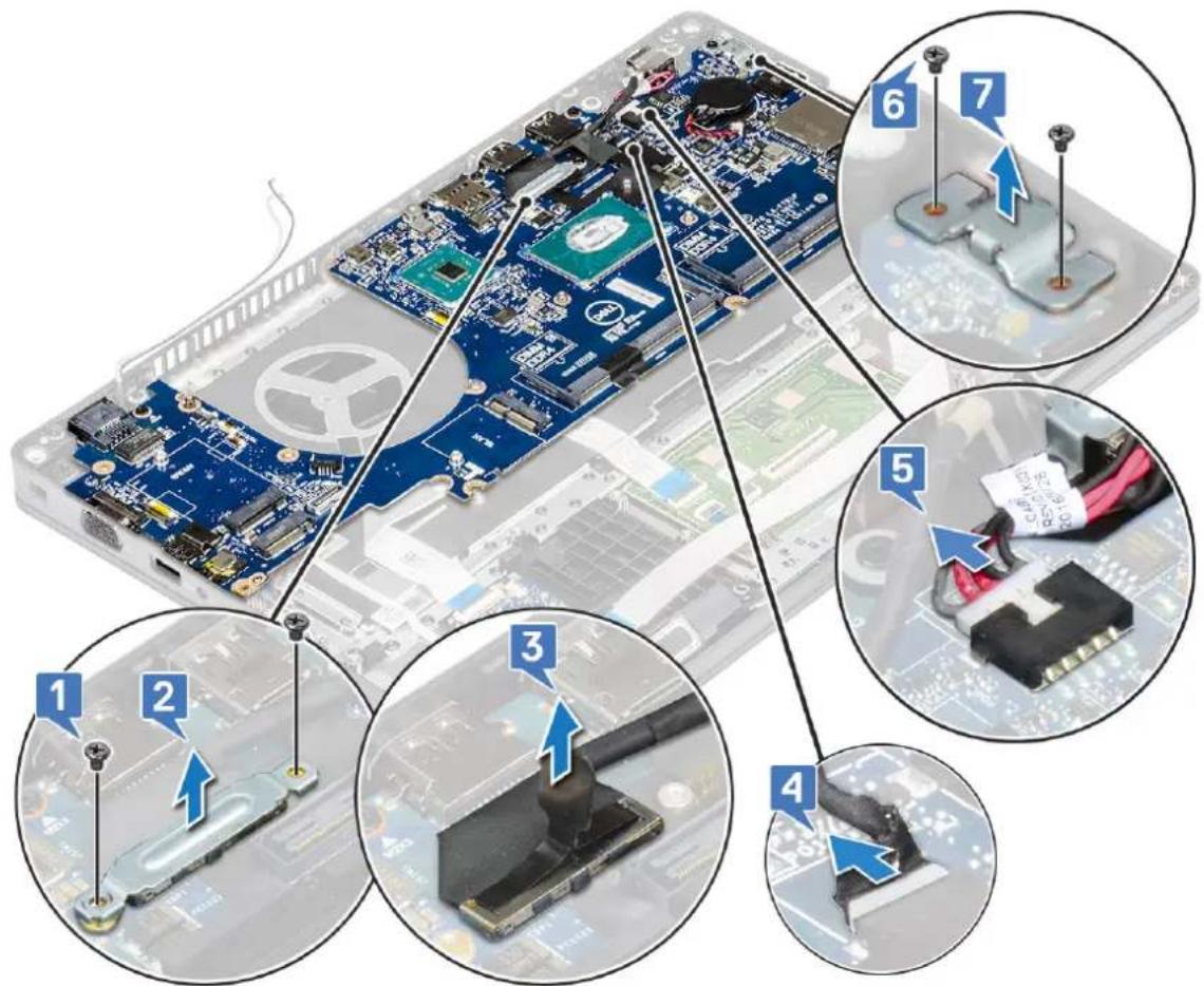
- Disconnect the following cables from the system board:
a. Touchpad cable [1]
b. USH cable [2]
c. LED board cable [3]
d. Speaker cable [4]
text_image
Laptop screen setup diagram with four labeled views showing internal components and connected devices, including USB drive and memory chips.- To release the system board:
a. Flip over the system and remove the two M2x3 screw that secure the display cable bracket in place [1].
b. Lift the metal display cable bracket from the system [2].
c. Disconnect the display cables from the connectors on the system board [3,4] and peel the adhesive tape securing the display cable to the system.
d. Disconnect the power connector port cable from the connector on the system board [5].
e. Remove the two M2x5 screws that secure the Type-C USB bracket in place [6].

NOTE: The metal bracket secures the DisplayPort over USB Type-C.
f. Lift the metal bracket away from the system [7].
text_image
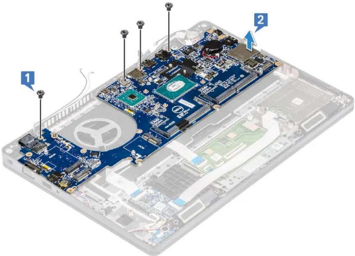
Labeled diagram of an electronic circuit board with numbered components and a close-up view showing internal components.- To remove the system board:

NOTE: Ensure SIM card tray is removed
a. Remove the four (M2x3) screws that secure the system board in place [1].
b. Lift the system board away from the system [2].
text_image
Labeled diagram of an open laptop showing internal components and parts with numbered annotationsInstalling system board
- Align the system board with the screw holders on the computer.

NOTE: Insert the cables through the openings in the keyboard area while placing the system board in the computer.
- Replace the four (M2x3) screws to secure the system board to the system.
- Place the metal bracket to secure the DisplayPort over USB Type-C.
- Replace the two (M2x3) screws to secure the metal bracket on the DisplayPort over USB Type-C.
- Connect the power connector port cable to the connector on the system board.
- Connect the display cables to the connectors on the system board and affix the tape that secures the display cable to the system.
- Place the display cable metal bracket over the display cable.
- Replace the two M2x3 screws to secure the metal bracket.
- Flip over the system and open the system in working mode.
- Connect the following cables:
a. Touchpad cable
b. LED board cable
c. USH board cable
d. speaker cable
- Install the:
a. system fan
b. chassis frame
c. heat sink
d. keyboard
e. keyboard lattice
f. WWAN card (optional)
g. WLAN card
h. SSD frame
i. SSD card
j. hard drive
k. memory module
I. battery
m. base cover
n. SIM card
- Follow the procedure in After working inside your computer.
Speaker
Removing the speaker
-
Follow the procedure in Before working inside your computer.
-
Remove the:
a. base cover
b. battery
c. memory module
d. hard drive
e. SSD card
f. SSD frame
g. WLAN card
h. WWAN card (optional)
i. keyboard lattice
j. keyboard
k. chassis frame
I. system board
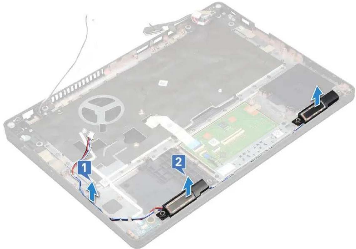
- To remove the speakers:
a. Release the speaker cable through the routing channels [1].
b. Lift the speaker away from the computer [2].
text_image
Laptop interior diagram with numbered annotations pointing to battery pack and cable connectionsInstalling the speaker
- Insert the speaker module aligning it with the nodes on the chassis.
- Route the speaker cable through the routing channels.
- Install the:
a. system board
b. chassis frame
c. keyboard
d. keyboard lattice
e. WLAN card
f. SSD frame
g. SSD card
h. hard drive
i. memory module
j. battery
k. base cover
I. SIM card
- Follow the procedure in After working inside your computer.
Display hinge cover
Removing display hinge cover
- Follow the procedure in Before working inside your computer.
- Remove the:
a. base cover
b. battery
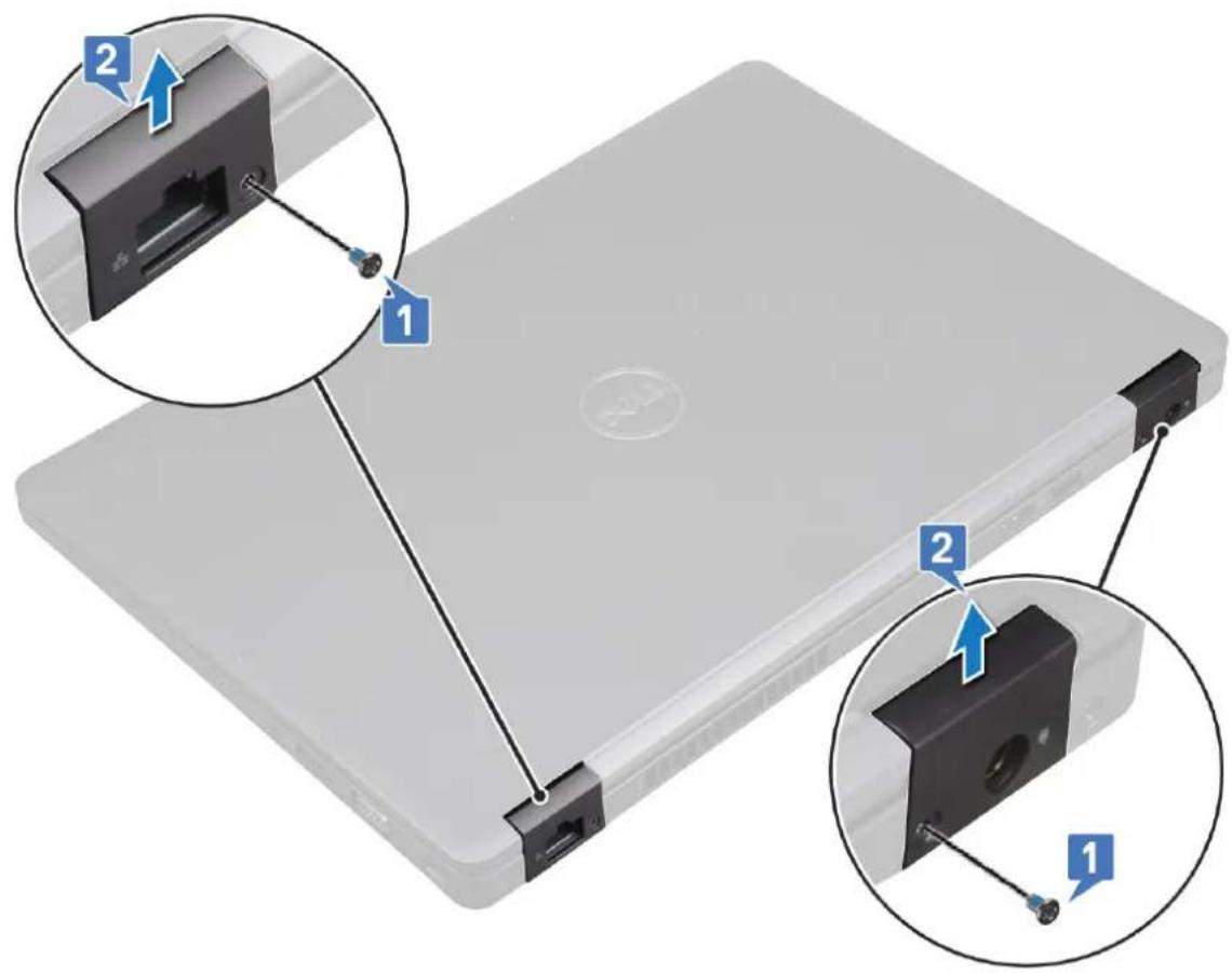
- To remove the display hinge cover:
a. Remove the M2x3 screw that secures the display hinge cover to the chassis [1].
b. Lift the display hinge cover away from the display hinge [2].
c. Repeat step a and step b to remove the other display hinge cover.
text_image
Diagram of a laptop with labeled ports and connectors, showing two zoomed-in views (labeled 1 and 2) highlighting internal components.Installing display hinge cover
- Place the display hinge cover on the display hinge.
- Replace the M2x3 screw to secure the display hinge cover to the display hinge.
- Repeat step 1 and step 2 to install the other display hinge cover.
- Install the:
a. battery
b. base cover - Follow the procedure in After working inside your computer.
Display assembly
Removing display assembly
- Follow the procedure in Before working inside your computer.
- Remove the:
a. base cover
b. battery
c. WLAN card
d. WWAN card (optional)
e. display hinge cover
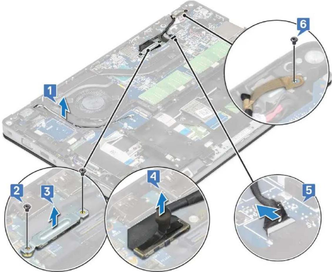
- To disconnect the display cable:
a. Release the WLAN and WWAN cables from the routing channels [1].
b. Remove the two (M2x3) screws that secure the display cable bracket in place [2].
c. Remove the display cable bracket that secures the display cable from the system [3].
d. Disconnect the display cables from their respective connectors on the system board [4,5].
e. Remove the single screw that secure the power connector bracket and also the display cable to the system [6].
text_image
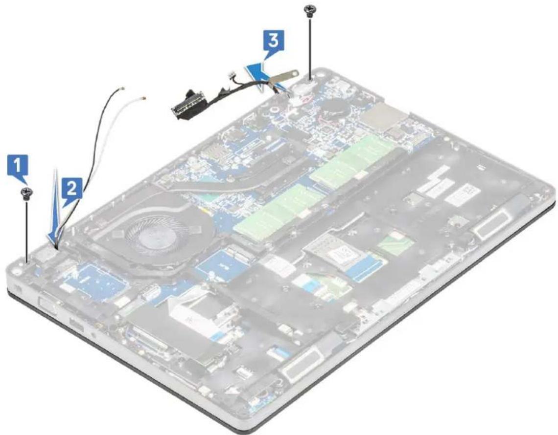
Laptop screen with numbered annotations pointing to internal components and cable installation steps- To release the display assembly:
a. Remove the two M2x5 screws that secure the display assembly to the computer [1].
b. Release the WLAN cable and display cable through the routing channels [2] [3].
text_image
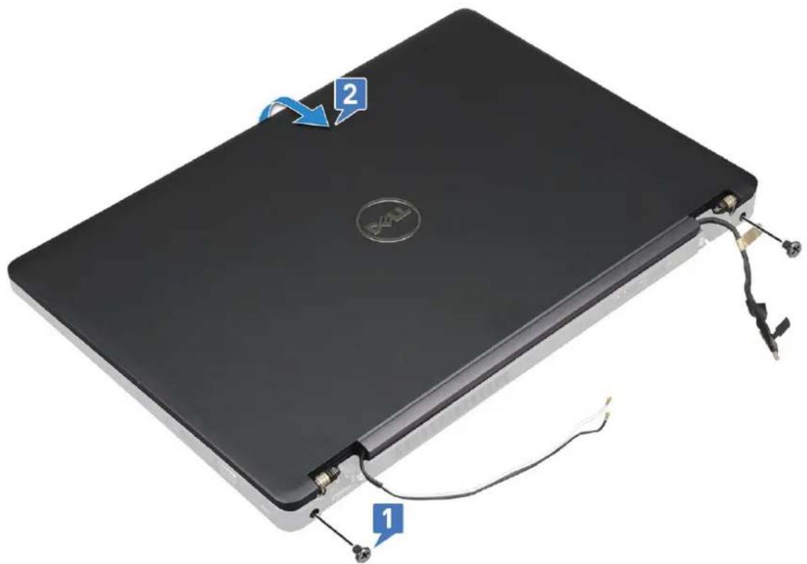
Labeled diagram of an open laptop showing internal components and cable connections, with numbered annotations pointing to key parts.- Turn over the computer.
- To remove the display assembly:
a. Remove the two M2x5 screws that secure the display assembly to the computer [1].
b. Open the display [2].
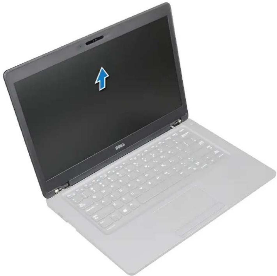
natural_image
Black laptop with attached cable and connectors, labeled parts 1 and 2 (no text or symbols on the device itself)c. Lift the display assembly from the computer.
natural_image
Laptop with a blue upward arrow icon on the screen (no text or symbols on the laptop body)Installing display assembly
- Place the chassis on a plane surface.
- Align the display assembly with the screw holders on the system and place it on the chassis.
- Close the display.
- Replace the two screws that secure the display assembly.
- Replace the screws that secure the power connector bracket and the display cable to the system.
- Flip over the system and replace two screws to secure the display assembly to the system.
- Replace the single screw that secure the power connector bracket and the display cable to the system.
- Connect the display cables to the connectors on the system board.
- Place the metal bracket to secure the display cable.
- Replace the (M2x3) screws to secure the metal bracket to the system.
- Route the WLAN and WWAN cables through the routing channels.
- Install the:
a. hinge cover
b. WWAN card (optional)
c. WLAN card
d. battery
e. base cover
- Follow the procedure in After working inside your computer.
Display bezel
Removing display bezel
- Follow the procedure in Before working inside your computer.
- Remove the:
a. base cover
b. battery
c. WLAN card
d. WWAN card (optional)
e. Display hinge cover
f. display assembly
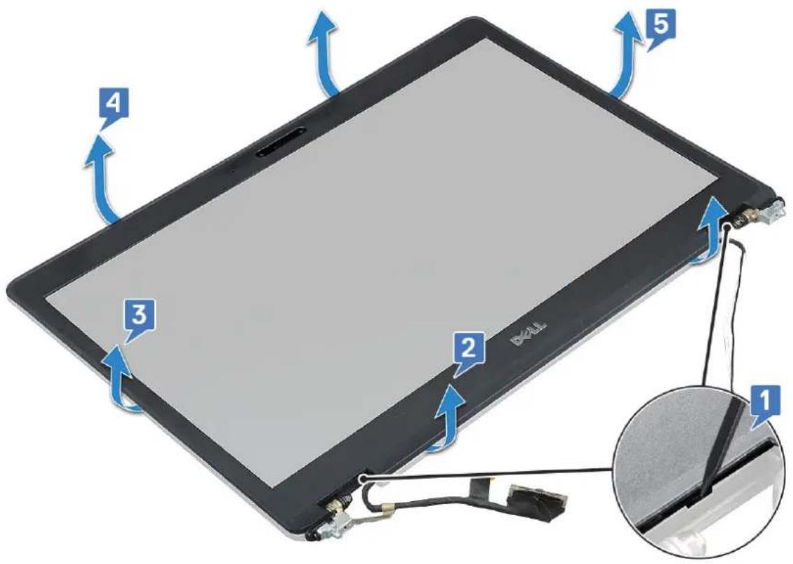
- To remove the display bezel:
a. Pry the display bezel at the base of the display [1].

NOTE: When removing or reinstalling the display bezel from the display assembly, technicians should note that the display bezel is secured to the LCD panel with a strong adhesive and care must be taken to avoid damage to LCD.
b. Lift the display bezel to release it [2].
c. Pry the edges on the side of the display to release the display bezel [3, 4,,5].

CAUTION: The adhesive used on the LCD bezel to seal it with the LCD itself, makes it hard to remove the bezel as the adhesive is very strong and tends to stay stuck to the LCD portion and can peel the layers up or crack the glass when trying to pry the two items apart.
text_image
1 2 3 4 5 RALLInstalling display bezel
- Place the display bezel on the display assembly.

NOTE: Remove the protective covering on the adhesive on the LCD bezel before placing on the display assembly.
- Starting from a top corner, press on the display bezel and work around the entire bezel until it clicks on to the display assembly.
- Install the:
a. display assembly
b. display hinge cover
c. WWAN card (optional)
d. WLAN card
e. battery
f. base cover
- Follow the procedure in After working inside your computer.
Display panel
Removing display panel
- Follow the procedure in Before working inside your computer.
- Remove the:
a. base cover
b. battery
c. WLAN card
d. WWAN card (optional)
e. display hinge cover
f. display assembly
g. display bezel
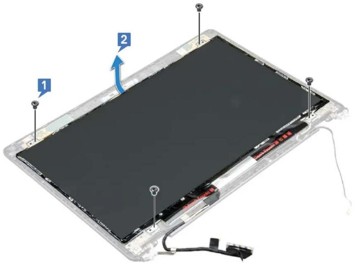
- Remove the four M2x3 screws that secure the display panel to the display assembly [1] and lift to turn over the display panel to access the display cable [2].
text_image
1 2 3 4 5 6 7 8 9 10 11 12 13 14 15 16 17 18 19 20 21 22 23 24 25 26 27 28 29 30 31 32 33 34 35 36 37 38 39 40 41 42 43 44 45 46 47 48 49 50 51 52 53 54 55 56 57 58 59 60 61 62 63 64 65 66 67 68 69 70 71 72 73 74 75 76 77 78 79 80- To remove the display panel:
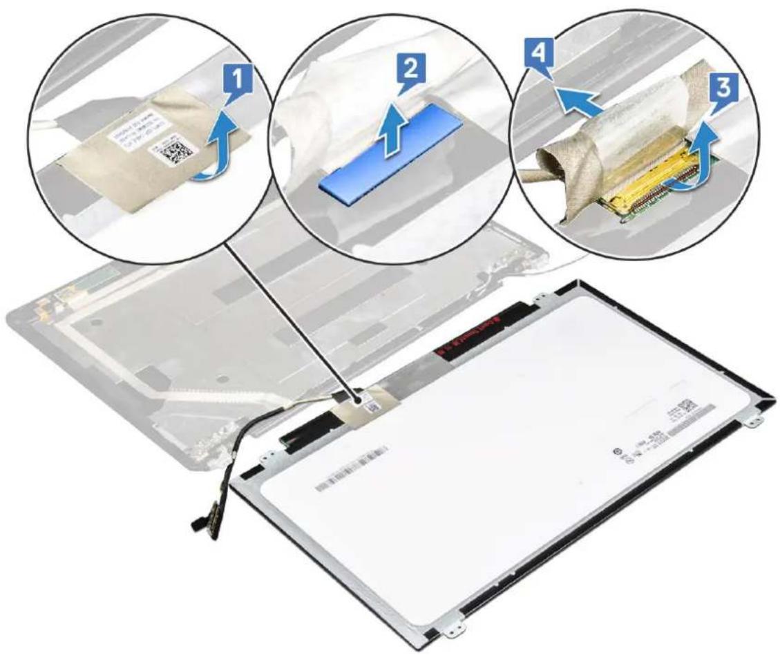
a. Peel the conductive tape [1].
b. Remove the adhesive strip that secures the display cable [2].
c. Lift the latch and disconnect the display cable from the connector on the display panel [3] [4].
text_image
1 2 3 4Installing display panel
- Connect the display cable to the connector and affix the adhesive strip.
- Affix the conductive tape to secure the display cable.
- Replace the display panel to align with the screw holders on the display assembly.
- Replace the four M2x3 screws to secure the display panel to the display back cover.
- Install the:
a. display bezel
b. display assembly
c. display hinge cover
d. WLAN card
e. WWAN card (optional)
f. battery
g. base cover
- Follow the procedure in After working inside your computer.
Display (eDP) cable
Removing display cable
- Follow the procedure in Before working inside your computer.
- Remove the:
a. base cover
b. battery
c. WLAN card
d. WWAN card (optional)
e. display hinge cover
f. display assembly
g. display bezel
h. display panel
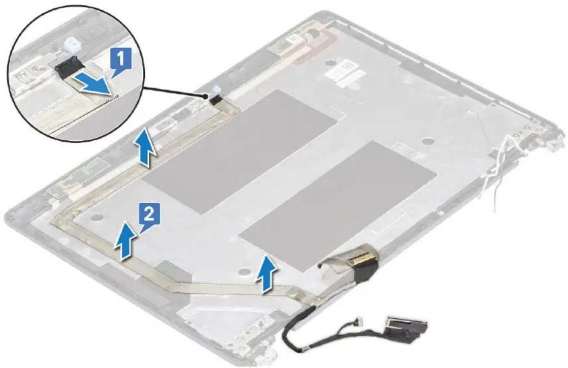
- Disconnect the camera cable from the connector on the camera module [1].
- Peel the display cable to release it from adhesive and lift the display cable from the display back cover [2].
text_image
Laptop interior diagram with numbered annotations indicating component placement and assembly stepsInstalling display cable
- Affix the display cable to the display back cover.
-
Connect the camera cable to the connector on camera module.
-
Install the:
a. display panel
b. display bezel
c. display assembly
d. display hinge cover
e. WLAN card
f. WWAN card (optional)
g. battery
h. base cover
- Follow the procedure in After working inside your computer.
Camera
Removing camera
- Follow the procedure in Before working inside your computer.
- Remove the:
a. base cover
b. battery
c. WLAN card
d. WWAN card (optional)
e. display hinge cover
f. display assembly
g. display bezel
h. display panel
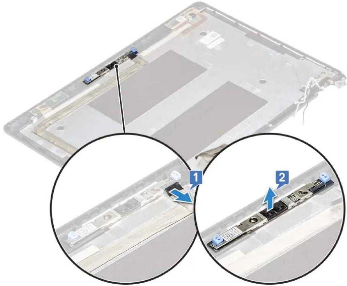
- To remove the camera:
a. Disconnect the camera cable from the connector on the camera module [1].
b. Carefully pry and lift the camera module from the display back cover [2].
text_image
Technical diagram showing a laptop with labeled parts and two zoomed-in views of the device's internal structure, marked with numbered annotations.Installing camera
- Insert the camera into the slot on the display back cover.
- Connect the camera cable to the connector on the camera module.
- Install the :
a. display panel
b. display bezel
c. display assembly
d. display hinge cover
e. WLAN card
f. WWAN card (optional)
g. memory module
h. battery
i. base cover
- Follow the procedure in After working inside your computer.
Display hinges
Removing display hinge
-
Follow the procedure in Before working inside your computer.
-
Remove the:
a. base cover
b. battery
c. WLAN card
d. WWAN card (optional)
e. display assembly
f. display bezel
g. display hinge cover
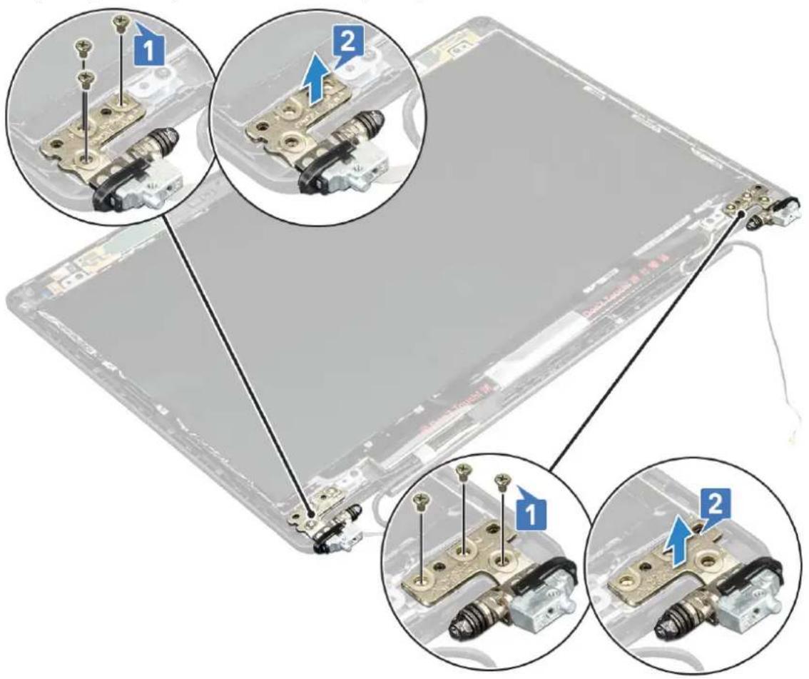
- To remove the display hinge:
a. Remove the 3 (M2.5x3) screws that secure the display hinge to the display assembly [1].
b. Lift the display hinge from the display assembly [2].
c. Repeat step a and step b to remove the other display hinge.
text_image
Diagram showing three views of a device with labeled components and arrows indicating assembly or installation steps.Installing display hinge
- Place the display hinge on the display assembly.
- Replace the 3 (M2.5x3) screws to secure the display hinge to the display assembly.
-
Repeat step 1 and step 2 to install the other display hinge.
-
Install the:
a. display hinge cover
b. display bezel
c. display assembly
d. WLAN card
e. WWAN card (optional)
f. battery
g. base cover
- Follow the procedure in After working inside your computer.
Display back cover assembly
Removing the display back cover assembly
-
Follow the procedure in Before working inside your computer.
-
Remove the:
a. base cover
b. battery
c. WLAN card
d. WWAN card (optional)
e. display hinge cover
f. display assembly
g. display bezel
h. display panel
i. display hinge
j. display cable
k. camera
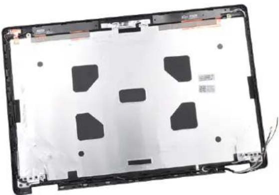
The display back cover assembly is the remaining component, after removing all the components.
natural_image
Laptop back panel showing exposed plastic casing with cutouts and mounting hardware (no text or symbols visible)Installing the display back cover assembly
-
Place the display back cover assembly on a flat surface.
-
Install the:
a. camera
b. display cable
c. display hinge
d. display panel
e. display bezel
f. display assembly
g. display hinge cover
h. WLAN card
i. WWAN card (optional)
j. battery
k. base cover
- Follow the procedure in After working inside your computer.
Palm rest
Removing palm rest
- Follow the procedure in Before working inside your computer.
- Remove the:
a. SIM card
b. base cover
c. battery
d. memory module
e. hard drive
f. SSD card
g. SSD frame
h. WLAN card
i. WWAN card (optional)
j. keyboard lattice
k. keyboard
I. heat sink
m. chassis frame
n. system fan
o. system board
p. display hinge cover
q. display assembly
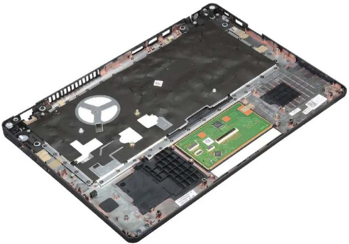
- The palm rest is the remaining component after removing all the components.
natural_image
Interior view of a laptop showing exposed circuit board, battery pack, and internal components (no text or symbols visible)Installing palm rest
- Place the palm rest on a flat surface.
- Install the:
a. display assembly
b. display hinge cover
c. system board
d. system fan
e. chassis frame
f. heat sink assembly
g. keyboard
h. keyboard lattice
i. WWAN card (optional)
j. WLAN card
k. SSD frame
I. SSD card
m. hard drive
n. memory module
o. battery
p. base cover
q. SIM card
- Follow the procedure in After working inside your computer.
Troubleshooting
Enhanced Pre-Boot System Assessment — ePSA diagnostics
The ePSA diagnostics (also known as system diagnostics) performs a complete check of your hardware. The ePSA is embedded with the BIOS and is launched by the BIOS internally. The embedded system diagnostics provides a set of options for particular devices or device groups allowing you to:
- Run tests automatically or in an interactive mode
- Repeat tests
• Display or save test results - Run thorough tests to introduce additional test options to provide extra information about the failed device(s)
- View status messages that inform you if tests are completed successfully
- View error messages that inform you of problems encountered during testing
CAUTION: Use the system diagnostics to test only your computer. Using this program with other computers may cause invalid results or error messages.
NOTE: Some tests for specific devices require user interaction. Always ensure that you are present at the computer terminal when the diagnostic tests are performed.
Running the ePSA Diagnostics
Invoke diagnostics boot by either of the methods that are suggested below:
- Power on the computer.
- As the computer boots, press the F12 key when the Dell logo is displayed.
- In the boot menu screen, use Up/Down arrow key to select the Diagnostics option and then press Enter.
NOTE: The Enhanced Pre-boot System Assessment window displays, listing all devices detected in the computer. The diagnostics starts running the tests on all the detected devices.
- Press the arrow in the lower-right corner to go to the page listing. The detected items are listed and tested.
- To run a diagnostic test on a specific device, press Esc and click Yes to stop the diagnostic test.
- Select the device from the left pane and click Run Tests.
- If there are any issues, error codes are displayed. Note the error code and contact Dell.
or
- Shut down the computer.
- Press and hold the Fn key, while pressing the power button, and then release both.
- Repeat steps 3–7 above.
Real Time Clock reset
The Real Time Clock (RTC) reset function allows you to recover your Dell system from No POST/No Boot/No Power situations. To initiate the RTC reset on the system make sure system is in a power-off state and is connected to power source. Press and hold the power button for 25 seconds and then release the power button. Go to how to reset real time clock.
NOTE: If AC power is disconnected from the system during the process or the power button is held longer than 40 seconds, the RTC reset process is aborted.
The RTC reset will reset the BIOS to Defaults, un-provision Intel vPro and reset the system date and time. The following items are unaffected by the RTC reset:
- Service Tag
- Asset Tag
- Ownership Tag
- Admin Password
- System Password
- HDD Password
- TPM on and Active
• Key Databases - System Logs
The following items may or may not reset based on your custom BIOS setting selections:
- The Boot List
- Enable Legacy OROMs
- Secure Boot Enable
- Allow BIOS Downgrade
Topics:
- Contacting Dell
Contacting Dell

NOTE: If you do not have an active Internet connection, you can find contact information on your purchase invoice, packing slip, bill, or Dell product catalog.
Dell provides several online and telephone-based support and service options. Availability varies by country and product, and some services may not be available in your area. To contact Dell for sales, technical support, or customer service issues:
- Go to Dell.com/support.
- Select your support category.
- Verify your country or region in the Choose a Country/Region drop-down list at the bottom of the page.
- Select the appropriate service or support link based on your need.