
MR2217 - Screen DELL - Free user manual and instructions
Find the device manual for free MR2217 DELL in PDF.


User questions about MR2217 DELL
0 question about this device. Answer the ones you know or ask your own.
Ask a new question about this device
Download the instructions for your Screen in PDF format for free! Find your manual MR2217 - DELL and take your electronic device back in hand. On this page are published all the documents necessary for the use of your device. MR2217 by DELL.
USER MANUAL MR2217 DELL
Dell MR2217 Medical Display User's Guide
Warnings, Cautions, and Notes

WARNING: A WARNING indicates a potential for property damage, personal injury, or death.
CAUTION: A CAUTION indicates potential damage to hardware or loss of data if instructions are not followed.

NOTE: A NOTE indicates important information that helps you make better use of your computer.
Copyright © 2016 Dell Inc. All rights reserved.
This product is protected by U.S. and international copyright and intellectual property laws.
Dell™ and the Dell logo are trademarks of Dell Inc. in the United States and/or other jurisdictions. All other marks and names mentioned herein may be trademarks of their respective companies.
Contents
1 Safety Information ....5
Symbols on the Device....5
Symbols on the Box 6
Intended Use 7
Warning....7
Regulatory compliance information 9
EMC notice 10
2 About Your Monitor ....13
Package Contents 13
Product Features 15
Identifying Parts and Controls 16
Monitor Specifications 19
Plug and Play Capability .....28
Universal Serial Bus (USB) Interface .....28
LCD Monitor Quality and Pixel Policy....29
Cleaning Your Monitor 30
3 Setting Up the Monitor ....31
Connecting Your Monitor....31
Attaching the Cable Cover....33
Attaching the Stand....34
Organizing Your Cables ....36
Connecting the Computer....36
Removing the Monitor Stand. 37
Removing the Cable Cover 37
Wall Mounting (Optional) 38
4 Operating the Monitor.... 39
Power On the Monitor 39
Using the Front Panel Controls ....39
Using the On-Screen Display (OSD) Menu ..... 41
Setting the Maximum Resolution .....54
Using the Tilt, Swivel, and Vertical Extension ..... 55
Rotating the Monitor....56
Adjusting the Rotation Display Settings of Your System ....58
5 Troubleshooting 59
Self-Test 59
Built-in Diagnostics....60
Common Problems....61
Product Specific Problems....63
Universal Serial Bus (USB) Specific Problems .....64
6 Appendix.... 65
Contact Dell....65
Setting Up Your Monitor....65
WARNING: Safety Instructions

WARNING: Use of controls, adjustments, or procedures other than those specified in this documentation may result in exposure to shock, electrical hazards, and/or mechanical hazards.
Please read safety and instructions for use before operating the device.
Please retain this user's guide for future reference.
For information on safety instructions, see the Safety, Environmental, and Regulatory Information.
Symbols on the Device
| Symbol Location Explanation | |
 | Rear Indicates manufacture's serial number. |
 | Rear Indicates the date of manufacture. |
 | Rear This device complies with local regulations for disposal of electronic products. |
 | Rear Follow operating instructions for use. |
 | Rear This device complies with Part 15 Class B of the FCC rules. |
| [03A0] | Rear Indicates Direct Current (DC). |
 | Rear Indicates the device is approved according to the cTUVus regulations. |
Symbols on the Box
| Symbol Explanation | |
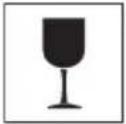 | Contents of the transport package are fragile therefore it shall be handled with care. |
 | Transport package shall be kept away from rain. |
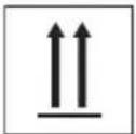 | Indicates correct upright position of the transport package. |
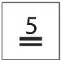 | Maximum number of identical packages that may be stacked, where "n" stands for the number of permitted packages |
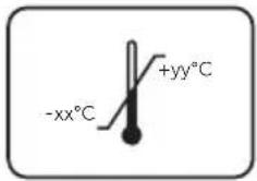 | Indicates temperature limits within which the transport package shall be stored and handled.NOTE: Values for "xx" and "yy" can be found in the Environmental Characteristics section. |
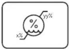 | Humidity limitation should be indicated adjacent to the upper and lower horizontal lines.NOTE: Values for "xx" and "yy" can be found in the Environmental Characteristics section. |
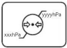 | Atmospheric pressure limitation should be indicated adjacent to the upper and lower horizontal lines.NOTE: Values for "xx" and "yy" can be found in the Environmental Characteristics section. |
 | Indicates that the fee has been paid for the recovery of the packaging material in some European countries. |
 | Indicates that an object is capable of being recycled. |
Intended Use
MR2217 is an LCD display intended used for trained physician or practitioners viewing medical images and data in hospital or clinic environment.
The device is neither used for life supporting system, surgical procedure system nor viewing digital mammography images.
Warning
You may get an electric shock if the AC outlet is not grounded properly.
Disconnecting Device
The power cord is the disconnect device for this monitor and is attached to the power adapter as a plug-in device. To remove all electrical power from the monitor, disconnect the power cord from the electrical outlet.
General recommendations
- For continued safe use of this monitor, read the safety and operating instructions before operating the monitor.
- Unplug the AC mains cord to disconnect the mains power.
- Use only the power cord supplied with this monitor.
- Adhere to all warnings on the device and in the operating instructions manual.
Electrical Shock or Fire Hazard
- Connect the AC power cord to a properly grounded power source with the line frequency and voltage specified on the name plate of the power adapter.
- To reduce the risk of electrical shock, DO NOT remove any covers. Refer servicing to qualified personnel only.
- Users must not allow SIP/SOPs and the patient to come into contact at the same time.
Modifications to the unit
No modification of this monitor is allowed.
Type of protection (electrical)
Monitor with external power adapter: Class I equipment.
Explosion Hazard
Do not use this monitor in the presence of flammable materials.
Power connection - Monitor with external +19VDC power adapter
- Power requirements: The monitor must be powered using the accompanied medical- approved power adapter.
- The medical-approved power adapter must be powered by AC mains power.
- The power adapter is specified as a part of the monitor.
Power cord
- Do not use extension cords as this may result in fire or electric shock.
- Use the power cord that is supplied with the monitor only.

NOTE: Grounding reliability can only be achieved when the equipment is connected to an equivalent receptacle marked "Hospital Only" or "Hospital Grade".
Connection of External Equipment
- External equipment intended for connection to signal input/output or other connectors, shall comply with relevant UL/EN/IEC standard (e.g. UL/EN/IEC 60950 for IT equipment and UL/EN 60601-1/IEC 60601 series for medical electrical equipment).
- In addition, all such combinations -systems- shall comply with the standard IEC 60601-1-1, safety requirements for medical electrical systems.
- Equipment not complying with UL/EN/IEC 60601-1 shall be kept outside the patient environment, as defined in the standard.
Regulatory compliance information
INDICATION FOR USE
MR2217 is an LCD display intended used for trained physician or practitioners viewing medical images and data in hospital or clinic environment.
The device neither be used for life supporting system, surgical procedure system nor viewing digital mammography images.
FCC Information
Federal Communications Commission (FCC) Notice (U.S. Only) WARNING: This equipment has been tested and found to comply with the limits for a digital device, pursuant to Part 15 Class B of the FCC Rules. These limits are designed to provide reasonable protection against harmful interference in a residential installation. This equipment generates, uses, and can radiate radio frequency energy and, if not installed and used in accordance with the instructions, may cause harmful interference to radio communications. However, there is no guarantee that interference will not occur in a particular installation. If this equipment does cause harmful interference to radio or television reception, which can be determined by turning the equipment off and on, the user is encouraged to try to correct the interference by one or more of the following measures:
- Reorient or relocate receiving antenna.
- Increase the separation between the equipment and receiver.
- Connect the equipment into an outlet on a circuit different from that to which the receiver is connected.
- Consult the dealer or an experienced radio/TV technician for help.
This device complies with Part 15 Class B of the FCC rules. Operation is subject to the following two conditions:
- This device may not cause harmful interference.
- This device must accept any interference received including interference that may cause undesired operation.
CAUTION: Changes or modifications not expressly approved by the party responsible for compliance could void the user's authority to operate the equipment.
CANADIAN NOTICE
Electromagnetic emissions
The MR2217 is intended for use in the electromagnetic environment specified below. The customer or the user of the MR2217 should assure that it is used in such an environment.
| Emissions test | Compliance | Electromagnetic environment - Guidance |
| RF emissionsCISPR 11 | Group 1 The MR22 | 17 uses RF energy only for its internal function.Therefore, its RF emissions are very low and are not likely to cause any interference in nearby electronic equipment. |
| RF emissionsCISPR 11 | Class B The MR22 | 17 is suitable for use in all establishments, including domestic establishments and those directly connected to the public low-voltage power supply network that supplies buildings used for domestic purposes. |
| Harmonic emissionsIEC 61000-3-2 | Class D | |
| Voltage fluctuations/flicker emissionsIEC 61000-3-3 | Complies |
Electromagnetic immunity
| Immunity test IEC 60601 Test levels | Compliance level | Electromagnetic environment - Guidance |
| Electrostatic discharge (ESD)IEC 61000-4-2 | ±6 kV contact±8 kV air | ±6 kV contact±8 kV air |
| Electrical fast transient/burstIEC 61000-4-4 | ±2 kV for power supply lines±1 kV for input/output lines | ±2 kV for power supply lines±1 kV for input/output lines |
| SurgeIEC 61000-4-5 | ±1 kV line(s) to line(s)±2 kV line(s) to earth | ±1 kV line(s) to line(s)±2 kV line(s) to earth |
| Voltage dips, short interruptions and voltage variations on power supply input linesIEC 61000-4-11 | < 5% U_T 1 (>95% dip in U_T ) for 0.5 cycle40% U_T (60% dip in U_T ) for 5 cycles70% U_T (30% dip in U_T ) for 25 cycles< 5% U_T (>95% dip in U_T ) for 5s | < 5% U_T (>95% dip in U_T ) for 0.5 cycle40% U_T (60% dip in U_T ) for 5 cycles70% U_T (30% dip in U_T ) for 25 cycles< 5% U_T (>95% dip in U_T ) for s | Mains power quality should be that of a typical commercial or hospital environment. If the user of the MR2217 requires continued operation during power mains interruptions, it is recommended that the MR2217 be powered from an uninterruptible power supply or a battery. |
| Power frequency (50/60 Hz)magnetic fieldIEC 61000-4-8 | 3 A/m 3 A/m Power | frequency magnetic fields | should be at least characteristic of a typical location in a typical commercial or hospital environment. |
| Conducted RFIEC 61000-4-6Radiated RFIEC 61000-4-3 | 3 Vrms150 kHz to 80 MHz3 V/m80 MHz to 2.5 GHz | 3 Vrms3 V/m | Portable and mobile RF communications equipment should be used no closer to any part of the OEV262H, including cables, than the recommended separation distance calculated from the equation appliance to the frequency of the transmitter.Recommended separation distance: d = 1.2 d = 1.2 80 MHz to 800 MHz d = 2.3 800 MHz to 2.5 GHzWhere P is the maximum output power rating of the transmitter in watts (W) according to the transmitter manufacturer and d is the recommended separation distance in meters (m).Field strengths from fixed RF transmitters, as determined by an electromagnetic site survey^a , should be less than the compliance level in each frequency range^b . Interference may occur in the vicinity of equipment marked with following symbol:[IMAGE] |
| NOTE: At 80 MHz and 800 MHz, the higher frequency range applies.NOTE: These guidelines may not apply in all situations. Electromagnetic propagation is affected by absorption and reflection from structures, objects and people. |
| a. Field strengths from fixed transmitters, such as base stations for radio (cellular/cordless) telephones and land mobile radios, amateur radio, AM and FM radio broadcast and TV broadcast cannot be predicted theoretically with accuracy. To assess the electromagnetic environment due to fixed RF transmitters, an electromagnetic site survey should be considered. If the measured field strength in the location in which the MR2217 is used exceeds the applicable RF compliance level above, the MR2217 should be observed to verify normal operation. If abnormal performance is observed, additional measures may be necessary, such as reorienting or relocating the MR2217.b. Over the frequency range 150 kHz to 80 MHz, field strengths should be less than 3 V/m. |
Recommended separation distance
The MR2217 display is intended for use in an electromagnetic environment in which radiated RF disturbances are controlled. The customer of the user or the MR2217 display can help prevent electromagnetic interference by maintaining a minimum distance between portable and mobile RF communications equipment (transmitters) and the MR2217 display as recommended below, according to the maximum output power of the communications equipment.
| Rated maximum output power of transmitter (W) | Separation distance according to frequency of transmitter (m) | ||
| 150kHz to 80MHz d=1.2√P | 80MHz to 800MHz d=1.2√P | 800MHz to 2.5GHz d=2.3√P | |
| 0.01 0.12 0.12 0.23 | |||
| 0.1 0.38 0.38 0.73 | |||
| 1 1.2 1.2 2.3 | |||
| 10 3.8 3.8 7.3 | |||
| 100 | 12 | 12 | 23 |
| For transmitters rated at a maximum output power not listed above, the recommended separation distance "d" in meters (m) can be estimated using the equation applicable to the frequency of the transmitter, where "P" is the maximum output power rating of the transmitter in watts (W) according to the transmitter manufacturer.NOTE: At 80 MHz and 800 MHz, the separation distance for the higher frequency range applies.NOTE: These guidelines may not apply in all situations. Electromagnetic propagation is affected by absorption and reflection from structures, objects and people. | |||
Package Contents
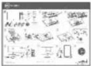
Your monitor ships with the components shown below. Ensure that you have received all the components and Contact Dell if something is missing.

NOTE: Some items may be optional and may not ship with your monitor. Some features or media may not be available in certain countries.

NOTE: To set up with any other stand, please refer to the respective stand setup guide for setup instructions.
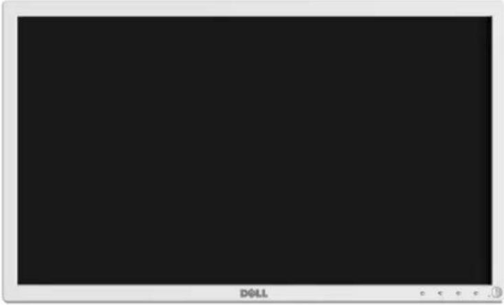 | Monitor | |||
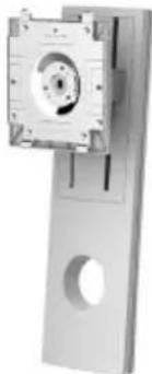 | Stand Riser | |||
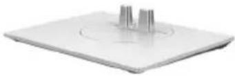 | Stand Base | |||
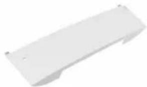 | Cable Cover | |||
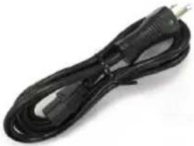 | DC Power Cable | |||
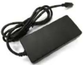 | Power Adapter | |||
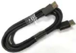 | DP Cable | |||
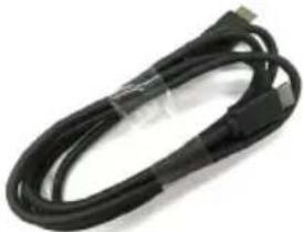 | HDMI Cable | |||
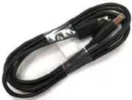 | USB 2.0 Upstream Cable(Enables the USB Ports onthe Monitor) | |||
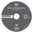 |  |  | 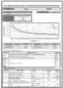 | • Drivers andDocumentation Media• Quick Setup Guide• Safety, Environmental,and RegulatoryInformation• Factory CalibrationReport |
Product Features
The Dell MR2217 flat panel medical display has an active matrix, Thin-Film Transistor (TFT), Liquid Crystal Display (LCD) and LED backlight. The monitor features include:
- 54.61 cm (21.5-inch) viewable area display (measured diagonally). 1920 x 1080 resolution, plus full-screen support for lower resolutions.
- Wide viewing angle to allow viewing from a sitting or standing position, or while moving from side-to-side.
- Tilt, swivel, height, and rotate adjustment capabilities.
- Removable stand and Video Electronics Standards Association (VESA™) 100 mm mounting holes for flexible mounting solutions.
• Digital connectivity with DisplayPort and HDMI.
- Equipped with 1 USB upstream port and 2 USB downstream ports.
- Plug and play capability if supported by your system.
- On-Screen Display (OSD) adjustments for ease of set-up and screen optimization.
- Software and documentation media includes an Information File (INF), Image Color Matching File (ICM), and product documentation.
- Dell Display Manager Software included (comes in the CD shipped with the monitor).
• Security lock slot and cable clip.
- Capability to switch from wide aspect to standard aspect ratio while maintaining the image quality.
- BFR/PVC/CFR-free (Halogen-free) excluding the external cables and power adapter.
- Meets NFPA 99 leakage current requirements.
- Arsenic-Free glass and Mercury-Free for the panel only.
- 0.5 W standby power when in the sleep mode.
• Energy Gauge shows the energy level being consumed by the monitor in real time.
- Analog backlight dimming control for flicker free display.
• DICOM (Digital Imaging and Communications in Medicine) part-14 GFDS for accurate grayscale reproducibility. DICOM calibrated luminance at 180 cd/m^2 .
• FDA Class I and medical grade display.
- Integrated backlight sensing for brightness stabilization.
- Cable security and management.
- 10-bit LUT and color processing.
- White housing for visible dried blood stains detection.
Identifying Parts and Controls
Front View
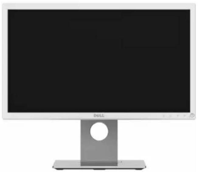
natural_image
Front view of a Microsoft DELL desktop computer monitor with a blank screen and stand (no text or symbols visible)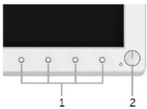
text_image
1 2Front panel controls
| Label | Description |
| 1 | Function buttons (For more information, see Operating the Monitor) |
| 2 | Power On/Off button (with LED indicator) |
Side View
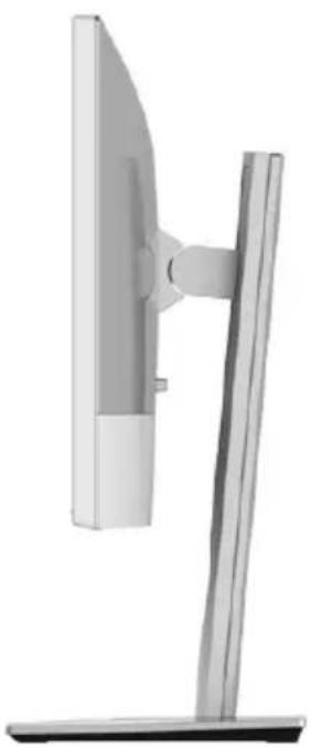
natural_image
Side view of a computer monitor with a stand (no text or symbols visible)Back View
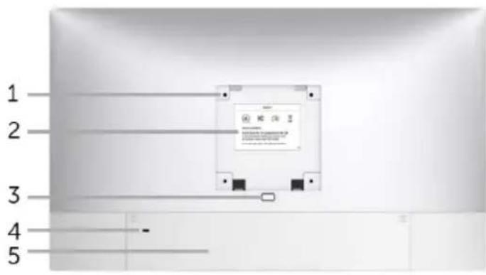
text_image
1 2 3 4 5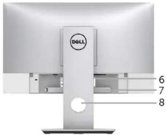
text_image
D&LL 6 7 8Back view with monitor stand
| Label | Description Use | |
| 1 | VESA mounting holes(100 mm x 100 mm - behind attached VESA Cover) | Wall mount monitor using VESA-compatible wall mount kit (100 mm x 100 mm). |
| 2 | Regulatory label Lists the regulatory approvals. | |
| 3 | Stand release button Releases | stand from monitor. |
| 4 | Security lock slot | Supports the use of security lock to prevent theft.(security lock not included) |
| 5 | Cable cover | Offers the protection to the installed cables on the rear of the monitor. |
| 6 | Barcode serial number label | Refer to this label if you need to contact Dell for technical support. |
| 7 | Cable clip | Use to secure the cables by tightening the screw on the clip. |
| 8 | Cable management slot | Use to organize cables by placing them through the slot. |
Bottom View
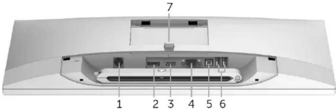
text_image
1 2 3 4 5 6 7Bottom view without monitor stand
| Label | Description Use | |
| 1 | Adapter connector Connect the power cable. | |
| 2 | DisplayPort in connector | Connect your computer with DP cable. |
| 3 | HDMI port connector | Connect your computer with HDMI cable. |
| 4 | VGA connector | Connect your computer with VGA cable (cable not included). |
| 5 | USB upstream port | Connect the USB cable that came with your monitor to the monitor and the computer. Once this cable is connected, you can use the USB connectors on the monitor. |
| 6 | USB downstream port | Connect your USB device. You can only use this connector after you have connected the USB cable to the computer and USB upstream connector on the monitor. |
| 7 | Stand release button Releases stand from monitor. | |
Monitor Specifications
Flat Panel Specifications
| Model MR2217 | |
| Screen type Active matrix - TFT LCD | |
| Panel type In-Plane Switching type | |
| Viewable image | |
| Diagonal Horizontal, Active Area Vertical, Active Area Area | 546.1 mm (21.5 inches) 476.06 mm (18.74 inches) 267.78 mm (10.54 inches) 127479.35 mm^2 (197.59 inch ^2 ) |
| Pixel pitch 0.248 mm x 0.248 | mm |
| Viewing angle 178° (vertical) | typical 178° (horizontal) typical |
| Luminance output 250 cd/ m^2 (typical) | |
| Contrast ratio 1000 to 1 (typical) | |
| Faceplate coating Anti-Glare | with 3H hardness |
| Backlight LED edgelight system | |
| Response time 14 ms (Gray to Gray) | |
| Color depth 16.7 million colors | |
| Color gamut 72% (typical)* | |
* MR2217 color gamut (typical) is based on CIE1976 (85%) and CIE1931 (72%) test standards.
Resolution Specifications
| Model MR2217 | |
| Horizontal scan range 30 kHz to 83 kHz (automatic) | |
| Vertical scan range 50 Hz to 76 Hz (automatic) | |
| Maximum preset resolution | 1920 x 1080 at 60 Hz |
Preset Display Modes
| Display Mode Horizontal Frequency (kHz) | Vertical Frequency (Hz) | Pixel Clock (MHz) | Sync Polarity (Horizontal/ Vertical) |
| VESA, 720 x 400 | 31.5 | 70.1 | -/+ |
| VESA, 640 x 480 | 31.5 | 60.0 | -/- |
| VESA, 640 x 480 | 37.5 | 75.0 | -/- |
| VESA, 800 x 600 | 37.9 | 60.3 | +/+ |
| VESA, 800 x 600 | 46.9 | 75.0 | +/+ |
| VESA, 1024 x 768 | 48.4 | 60.0 | -/- |
| VESA, 1024 x 768 | 60.0 | 75.0 | +/+ |
| VESA, 1152 x 864 | 67.5 | 75.0 | +/+ |
| VESA, 1280 x 1024 | 63.9 | 60.0 | +/+ |
| VESA, 1280 x 1024 | 80.0 | 75.0 | +/+ |
| VESA, 1600 x 900 | 60.0 | 60.0 | +/+ |
| VESA, 1920 x 1080 | 67.5 | 60.0 | +/+ |
Electrical Specifications
| Model MR2217 | ||
| Video input signals • Analog RGB | , 0.7 Volts +/- 5%, positive polarity at 75 ohm input impedanceHDMI 1.4*, 600mV for each differential line, 100 ohm input impedance per differential pairDisplayPort 1.2**, 600mV for each differential line, 100 ohm input impedance per differential pair | |
| Synchronization input signals Se | Separate horizontal and vertical synchronizations, polarity-free TTL level, SOG (Composite SYNC on green) | |
| AC/DC adapter*** | Input voltage/frequency/current | 100V to 250 V ~ 1.5A to 0.75A/50Hz to 60Hz |
| Output voltage/current | Output: 19 V/3.15 A | |
| Inrush current • 115 V | : 50 A (Max.) at 25 °C (cold start)• 230 V: 100 A (Max.) at 25 °C (cold start) | |
* Support HDMI 1.4 specification, Excludes HDMI Ethernet Channel (HEC), Audio Return Channel (ARC), standard for 3D format and resolutions, standard for 4K x 2K resolution.
** Support DP1.2 (CORE) specification, Excludes High Bit Rate 2 (HBR2), Fast AUX transaction, Multi-stream transport (MST), 3D stereo transport, HBR Audio (or high data rate audio).
*** Qualified Compatible AC/DC adapters.
CAUTION: To avoid damage to the monitor, use only the adapter designed for this particular Dell monitor.
| Manufacturer Model Polarity | ||
| Delta MDS-060AAS19 B Signal | 1 DC +19V2 DC +19V3 RTN4 RTN | |
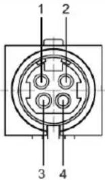 | ||
Physical Characteristics
| Model MR2217 | |
| Connector type 15-pin D-subminiature; DP; HDMI; USB 2.0 | |
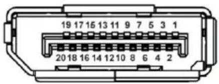
| Signal cable type • Analog: | D-Sub, 15 pins (cable not included)• Digital: HDMI, 19 pins• Digital: DisplayPort, 20 pins• Universal Serial Bus: USB, 4 pins |
| Dimensions (with stand) | |
| Height (extended) | 483.4 mm (19.03 inches) |
| Height (compressed) | 353.4 mm (13.91 inches) |
| Width | 507.3 mm (19.97 inches) |
| Depth | 180.0 mm (7.09 inches) |
| Dimensions (without stand) | |
| Height | 305.4 mm (12.02 inches) |
| Width | 507.3 mm (19.97 inches) |
| Depth | 50.2 mm (1.98 inches) |
| Stand dimensions | |
| Height (extended) | 400.7 mm (15.78 inches) |
| Height (compressed) | 354.4 mm (13.95 inches) |
| Width | 242.6 mm (9.55 inches) |
| Depth | 180.0 mm (7.09 inches) |
| Weight | |
| Weight with packaging | 7.8 kg (17.10 lb) |
| Weight with stand assembly and cables | 5.7 kg (12.50 lb) |
| Weight without stand assembly (For wall mount or VESA mount considerations - no cables) | 2.8 kg (6.12 lb) |
| Weight of stand assembly | 2.0 kg (4.40 lb) |
Environmental Characteristics
| Model MR2217 | |
| Pressure | |
| Operating | 70 kPa to 101 kPa |
| Non-operating | 20 kPa to 101 kPa |
| Temperature | |
| Operating | 0 °C to 40 °C (32 °F to 104 °F) |
| Non-operating | Storage: -20 °C to 60 °C (-4 °F to 140 °F)Sh ipping: -20 °C to 60 °C (-4 °F to 140 °F) |
| Humidity | |
| Operating | 10% to 80% (non-condensing) |
| Non-operating | Storage: 5% to 90% (non-condensing)Sh ipping: 5% to 90% (non-condensing) |
| Altitude | |
| Operating | 3,000 m (9,842 ft) (maximum) |
| Non-operating | 12,192 m (40,000 ft) (maximum) |
| Thermal dissipation • 102.36 | BTU/hour (maximum)68.24 BTU/hour (typical) |
Regulatory Compliance
| Certification MR2217 |
| FDA Class I, ANSI/AAMI ES 60601-1, CAN/CSAC22.2 No. 60601-1, FCC Part 15 Class B, ICES-003 Level B, IEC/EN 60601-1, IEC/EN 60601-1-2 |
Power Management Modes
If you have VESA's DPM™ compliance display card or software installed in your PC, the monitor can automatically reduce its power consumption when not in use. This is referred to as Power Save Mode*. If the computer detects input from the keyboard, mouse, or other input devices, the monitor automatically resumes functioning. The following table shows the power consumption and signaling of this automatic power saving feature.
| VESA Modes | Horizontal Sync | Vertical Sync | Video Power Indicator | Power Consumption |
| Normal operation | Active | Active | Active | Green30 W (maximum)**20 W (typical) |
| Active-off mode | Inactive | Inactive | Blanked | AmberLess than 0.5 W |
| Switch off | - | - | - | AmberLess than 0.5 W |
* Zero power consumption in OFF mode can only be achieved by disconnecting the main cable from the monitor.
** Maximum power consumption with max luminance, and USB active.
The OSD functions only in the normal operation mode. When any button is pressed in the Active-off mode, the following message will be displayed:
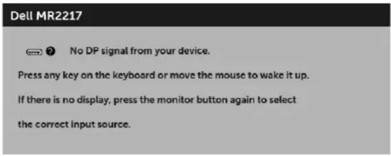
text_image
Dell MR2217 No DP signal from your device. Press any key on the keyboard or move the mouse to wake it up. If there is no display, press the monitor button again to select the correct input source.
NOTE: The message may be slightly different according to the connected input signal.
Activate the computer and the monitor to gain access to the OSD.
Pin Assignments
VGA Connector
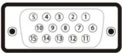
text_image
⑤ ④ ③ ② ① ⑩ ⑨ ⑧ ⑦ ⑥ ⑮ ⑭ ⑬ ⑭ ⑮| Pin Number | 15-pin Side of the Connected Signal Cable |
| 1 Video-Red | |
| 2 Video-Green | |
| 3 Video-Blue | |
| 4 GND | |
| 5 Self-test | |
| 6 GND-R | |
| 7 GND-G | |
| 8 GND-B | |
| 9 Computer 5 V/3.3 V | |
| 10 GND-sync | |
| 11 GND | |
| 12 DDC data | |
| 13 H-sync | |
| 14 V-sync | |
| 15 DDC clock | |
DisplayPort Connector
text_image
19 17 15 13 11 9 7 5 3 1 20 18 16 14 12 10 8 6 4 2| Pin Number | 20-pin Side of the Connected Signal Cable |
| 1 | ML0(p) |
| 2 | GND |
| 3 | ML0(n) |
| 4 | ML1(p) |
| 5 | GND |
| 6 | ML1(n) |
| 7 | ML2(p) |
| 8 | GND |
| 9 | ML2(n) |
| 10 | ML3(p) |
| 11 | GND |
| 12 | ML3(n) |
| 13 | GND |
| 14 | GND |
| 15 | AUX(p) |
| 16 | GND |
| 17 | AUX(n) |
| 18 | GND |
| 19 | Re-PWR |
| 20 | +3.3 V DP_PWR |
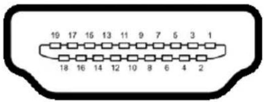
text_image
19 17 15 13 11 9 7 5 3 1 18 16 14 12 10 8 6 4 2| Pin Number | 19-pin Side of the Connected Signal Cable |
| 1 | TMDS DATA 2+ |
| 2 | TMDS DATA 2 SHIELD |
| 3 | TMDS DATA 2- |
| 4 | TMDS DATA 1+ |
| 5 | TMDS DATA 1 SHIELD |
| 6 | TMDS DATA 1- |
| 7 | TMDS DATA 0+ |
| 8 | TMDS DATA 0 SHIELD |
| 9 | TMDS DATA 0- |
| 10 | TMDS CLOCK+ |
| 11 | TMDS CLOCK SHIELD |
| 12 | TMDS CLOCK- |
| 13 | CEC |
| 14 | Reserved (N.C. on device) |
| 15 | DDC CLOCK (SCL) |
| 16 | DDC DATA (SDA) |
| 17 | DDC/CEC Ground |
| 18 | +5V POWER |
| 19 | HOT PLUG DETECT |
Plug and Play Capability
You can install the monitor in any Plug and Play-compatible system. The monitor automatically provides the computer system with its Extended Display Identification Data (EDID) using Display Data Channel (DDC) protocols so the system can configure itself and optimize the monitor settings. Most monitor installations are automatic; you can select different settings if desired. For more information about changing the monitor settings, see Operating the Monitor.
Universal Serial Bus (USB) Interface
This section gives you information about the USB ports that are available on the monitor.

NOTE: This monitor is High-Speed USB 2.0 compatible.
| Transfer Speed Data Rate Power Consumption* | ||
| High speed 480 Mbps | 2.5 W (Max, each port) | |
| Full speed 12 Mbps | 2.5 W (Max, each port) | |
| Low speed 1.5 Mbps | 2.5 W (Max, each port) | |
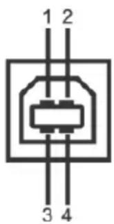
USB Upstream Connector
text_image
1 2 3 4| Pin Number 4-pin Side of the Connector |
| 1 DMU |
| 2 VCC |
| 3 DPU |
| 4 GND |
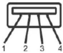
USB Downstream Connector
text_image
1 2 3 4| Pin Number 4-pin Side of the Connector |
| 1 VCC |
| 2 DMD |
| 3 DPD |
| 4 GND |
USB Ports
• 1 upstream - bottom
• 2 downstream - bottom
NOTE: USB 2.0 functionality requires a USB 2.0-capable computer.
NOTE: The monitor's USB interface works only when the monitor is On or in the power save mode. If you turn Off the monitor and then turn it On, the attached peripherals may take a few seconds to resume normal functionality.
LCD Monitor Quality and Pixel Policy
During the LCD Monitor manufacturing process, it is not uncommon for one or more pixels to become fixed in an unchanging state which are hard to see and do not affect the display quality or usability. For more information on Dell Monitor Quality and Pixel Policy, see Dell Support site at: http://www.dell.com/support/monitors.
Cleaning Your Monitor
CAUTION: Read and follow the Safety Instructions before cleaning the monitor.
CAUTION: Do not pour or spray any liquid directly on the device or permit fluid to seep into connections or openings.

WARNING: Before cleaning the monitor, unplug the monitor power cable from the electrical outlet.
For best practices, follow the instructions in the list below while unpacking, cleaning, or handling your monitor:
External Plastic surface
- For cleaning and disinfecting the plastic surface of the monitor, wipe the surface with a soft lint-free, lightly moistened cloth with up to 75% concentrated ethyl alcohol solution. Do not use strong alkali, strong solvents, acid and abrasive cleaning tools such as steel wool, steel blades and sponge with abrasives for cleaning to prevent damage and scratches to the monitor surface.
- Wipe off cleaning solutions with a clean and dry lint-free cloth if necessary. Monitor Panel surface
- If the surface of the panel becomes dusty, wipe gently with absorbent cotton with water, non-alcohol monitor wipes or other soft materials like chamois soaks with petroleum benzene.
- Do not use alcohol or ammonia (household cleaners/wipes) on the monitor panel surface as it will cause damage to the polarizer.

WARNING: Before you begin any of the procedures in this section, follow the Safety Instructions.

WARNING: The monitor is to be set up only by qualified personnel.
The following sections provide information about connecting your monitor to the computer. Please read carefully and follow the instructions given below to complete the monitor setup.
Connecting Your Monitor

NOTE: If your computer is turned on, turn it Off and disconnect the power cable before you start the following procedures.
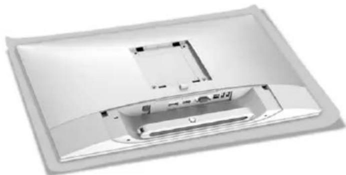
1 Remove the monitor protective cover and place the monitor with its front facing downward on it.
natural_image
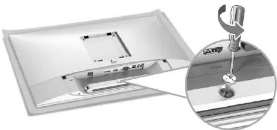
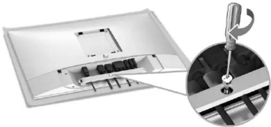
Interior view of a computer monitor case showing internal components and casing (no text or symbols visible)2 Use a Phillips crosshead screwdriver to loose the screw securing the cable clip.
natural_image
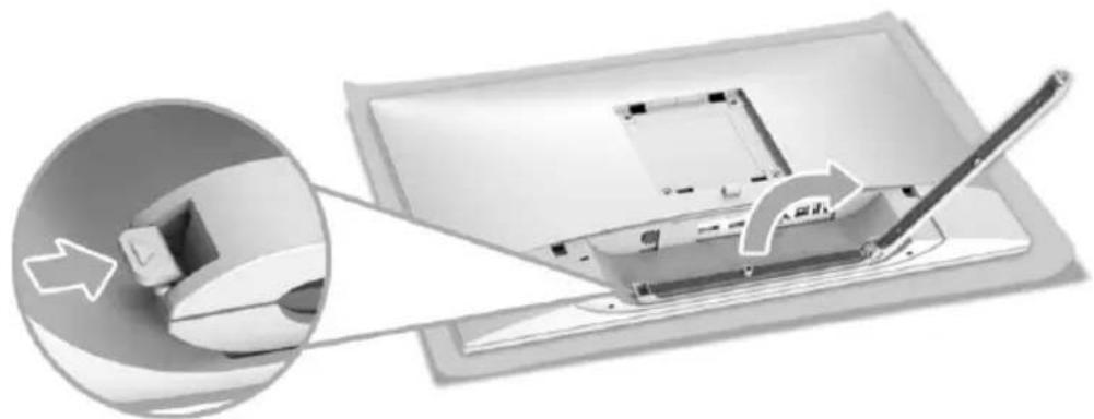
Diagram showing a computer monitor with internal components and a magnified view of the screen with a screwdriver inserted (no text or symbols present)3 Open the cable clip, as illustrated in the figure below.
natural_image
Diagram showing a computer monitor with a pen inserted, connected to a mouse (no text or symbols visible)4 Connect the necessary cables to the monitor.
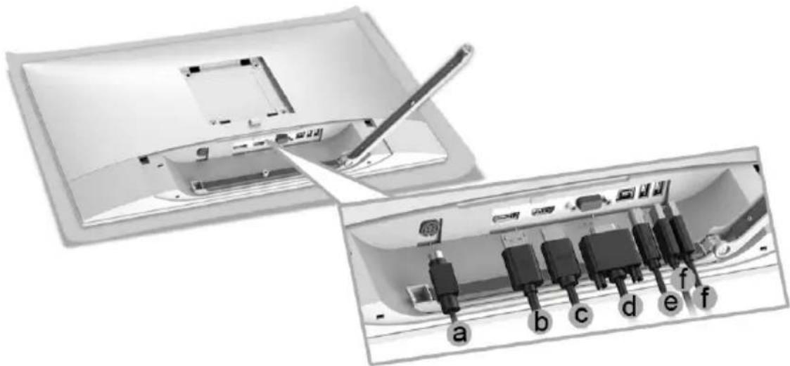
text_image
Diagram showing a device with labeled ports and a pen inserted into a panel, likely illustrating a cable or cable assembly.a DC power cable
b DP cable
c HDMI cable
d VGA cable (optional, cable not included)
e USB upstream cable
f USB downstream cables (optional, cable not included)
NOTE: Do not connect all cables to the computer at the same time.
NOTE: Route each cable neatly and properly as shown in the illustration.
NOTE: Ensure that the cables are placed in a balanced arrangement.
5 Tighten the cable clip screw with a Phillips crosshead screwdriver to secure all the connected cables.
natural_image
Diagram showing a mechanical assembly with a magnified inset of a tool inserted into a component (no text or symbols visible)
WARNING: Do not plug-in or turn-on the power to the monitor until you are instructed to do so.

NOTE: Read and follow the procedures in the following sections to continue setting up the monitor.
Attaching the Cable Cover

NOTE: The cable cover is detached when the monitor is shipped from the factory.

WARNING: Before turning on the power to the monitor, make sure the cable cover is well attached.
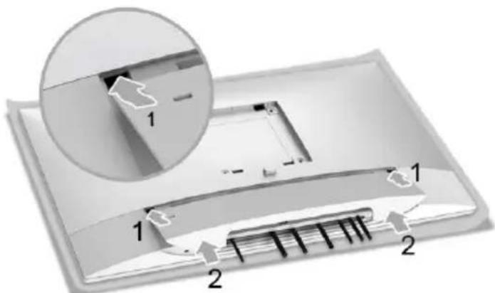
text_image
Diagram of a device with labeled components and an inset magnified view showing part 11 Fit the three tabs on the upper part of the cable cover to the groove on the back of the monitor.
2 Press the cable cover till it snaps into place.
Attaching the Stand

NOTE: The stand is detached when the monitor is shipped from the factory.

NOTE: This is applicable for a monitor with a stand. When any other stand is bought, please refer to the respective stand setup guide for the set up instructions.

WARNING: Do not plug-in or turn-on the power to the monitor until you are instructed to do so.
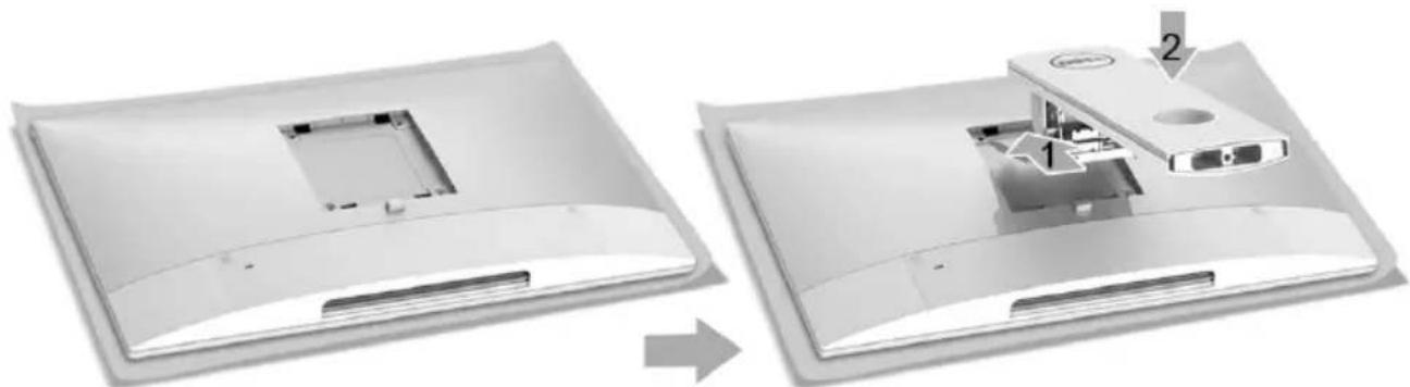
To attach the monitor stand:
1 Insert the two tabs on the upper part of the stand to the groove on the back of the monitor.
2 Pr ess the stand till it snaps into place.
natural_image
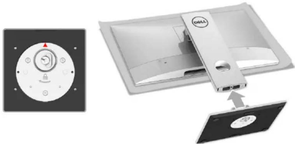
Two views of a device showing internal components before and after assembly (no text or symbols visible)3 Hold the stand base with the triangle mark, ▲, facing upward. Then, align the stand base protruded blocks to the matching slot on the stand.
natural_image
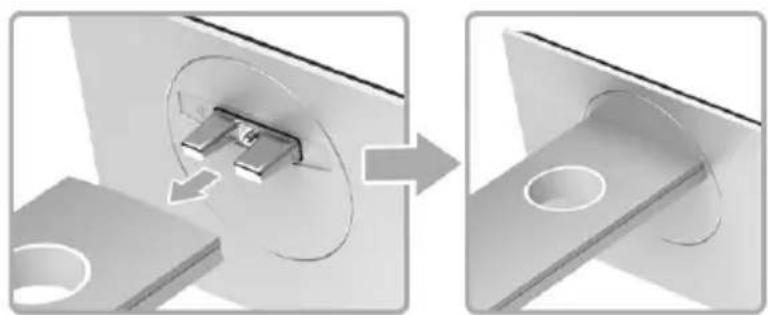
Diagram showing a DELL device with a lock mechanism and its internal components, alongside an open rear panel (no text or symbols)4 Insert the stand base blocks fully into the stand slot.
natural_image
Diagram showing a mechanical assembly with a component inserted into a housing, before and after assembly (no text or symbols)5 Lift the screw handle and turn the screw clockwise.

natural_image
Exterior view of a Dell drive showing internal components and mounting holes (no text or symbols)6 After fully tighten the screw, fold the screw handle flat within the recess.
Organizing Your Cables
natural_image
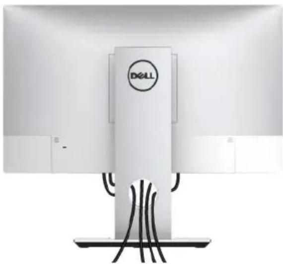
Exterior view of a Dell air conditioner unit with visible wiring and control panel (no text or symbols on main body)After attaching all necessary cables (see Organizing Your Cables), the cable cover (see Attaching the Cable Cover), and the monitor stand (see Attaching the Stand), organize all cables as shown above.
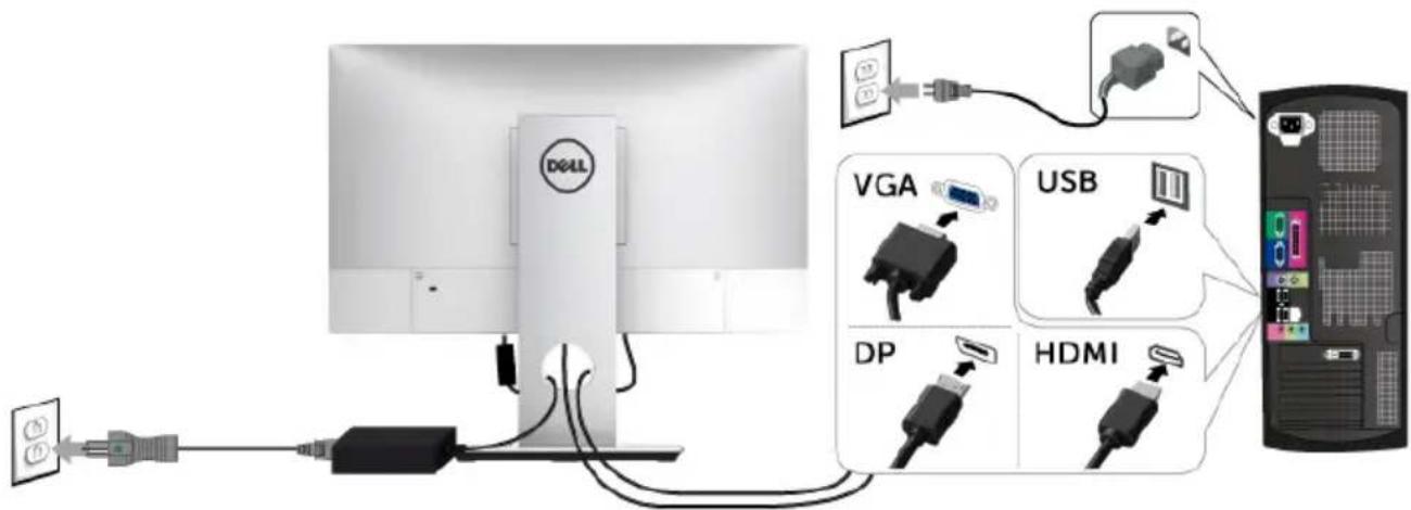
Connecting the Computer
To connect the monitor to your computer:

NOTE: See also Connecting Your Monitor.
text_image
DOLL VGA USB DP HDMI1 Plug the other end of the connected VGA or DP or HDMI cable to your computer.
2 Plug the USB upstream cable to an appropriate USB 2.0 port on your computer.
3 Connect the USB 2.0 peripherals to the downstream USB 2.0 ports on the monitor.
4 Plug the power cables for your computer and monitor into a nearby outlet.
5 T urn On the monitor and the computer.
CAUTION: The graphics are used for the purpose of illustration only. Appearance of the computer may vary.
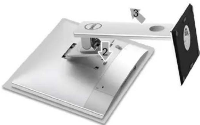
Removing the Monitor Stand

NOTE: To prevent scratches on the LCD screen while removing the stand, ensure that the monitor is placed on a soft, clean surface.

NOTE: This is applicable for a monitor with a stand. When any other stand is bought, please refer to the respective stand setup guide for the set-up instructions.
natural_image
Diagram of a foldable device with labeled parts (1, 2, 3), showing internal components and assembly (no text or symbols beyond labels)1 Place the mon itor on a soft cloth or cushion.
2 Pr ess and hold the stand release button.
3 Lift the stand up and away from the monitor.
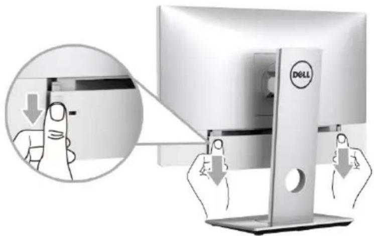
Removing the Cable Cover
text_image
Diagram showing a computer monitor with DELL logo and finger pressing a button, with an inset magnified view of the action.1 Place both of your thumbs on the two sides of the cable cover, as illustrated.
2 Slide the cable cover downward to remove it from the monitor.
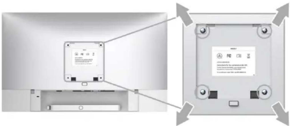
Wall Mounting (Optional)
text_image
Diagram showing device rear panel with labeled buttons and instructional text in Chinese(Screw dimension: M4 x 10 mm).
Refer to the instructions that come with the VESA-compatible wall mounting kit.
1 Place the mon itor panel on a soft cloth or cushion on a stable, flat table.
2 Remove the stand.
3 Use a Phillips crosshead screwdriver to remove the four screws securing the plastic cover.
4 Attach the mounting bracket from the wall mounting kit to the monitor.
5 Mount the monitor on the wall by following the instructions that comes with the wall mounting kit.

NOTE: For use only with UL-listed wall mount bracket with minimum weight/load bearing capacity of 10.8 kg.
Power On the Monitor

WARNING: Always make sure your hands are dry when operating the monitor.
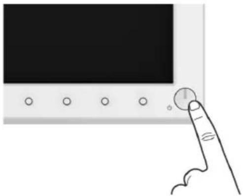
Press the Power button to turn On the monitor.
natural_image
Hand pointing at a finger pressing a button on a black screen (no text or symbols visible)Using the Front Panel Controls
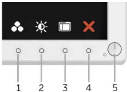
Use the control buttons on the front of the monitor to adjust the characteristics of the image being displayed. As you use these buttons to adjust the controls, an OSD shows the numeric values of the characteristics as they change.
text_image
1 2 3 4 5The following table describes the front panel buttons:
Front Panel Button Description
1

Shortcut key/Preset Modes
Use this button to choose from a list of preset color modes.
| 2 |  | Use this button to directly access the Brightness/Contrast menu. |
| Shortcut key/Brightness/Contrast | ||
| 3 |  | Use the MENU button to launch the On-Screen Display (OSD) and select the OSD Menu. See Accessing the Menu System. |
| Menu | ||
| 4 |  | Use this button to go back to the main menu or exit the OSD main menu. |
| Exit | ||
| 5 |  | Use the Power button to turn the monitor On and Off. The green light indicates the monitor is On and fully functional. An amber light indicates the power save mode. |
| Power (with power light indicator) |
Front Panel Button
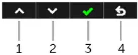
Use the buttons on the front of the monitor to adjust the image settings.
text_image
1 2 3 4| Front Panel Button Description | ||
| 1 |  | Use the Up button to adjust (increase ranges) items in the OSD menu. |
| Up | ||
| 2 |  | Use the Down button to adjust (decrease ranges) items in the OSD menu. |
| Down | ||
| 3 |  | Use the OK button to confirm your selection. |
| OK | ||
| 4 |  | Use the Back button to go back to the previous menu. |
| Back | ||
Using the On-Screen Display (OSD) Menu
Accessing the Menu System

NOTE: If you change the settings and then either proceed to another menu or exit the OSD menu, the monitor automatically saves those changes. The changes are also saved if you change the settings and then wait for the OSD menu to disappear.
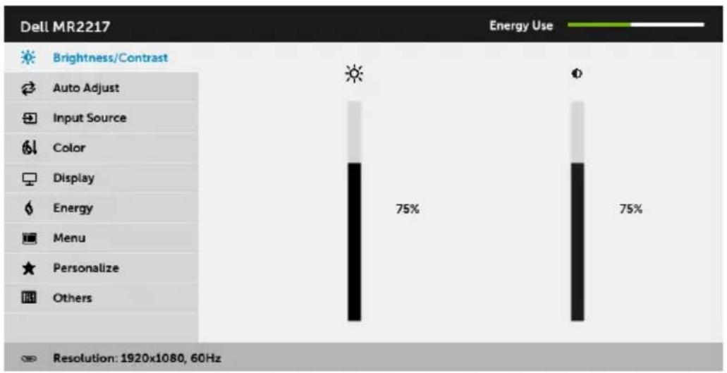
1 Press the

button to launch the OSD menu and display the main menu.
Main Menu for analog (VGA) input
bar
Dell MR2217 | Category | Energy Use (%) | | :--- | :--- | | Brightness/Contrast | 75 | | Auto Adjust | 75 | | Input Source | 75 | | Color | 75 | | Display | 75 | | Energy | 75 | | Menu | 75 | | Personalize | 75 | | Others | 75 | Resolution: 1920x1080, 60Hz
or
Main Menu for digital (HDMI) input
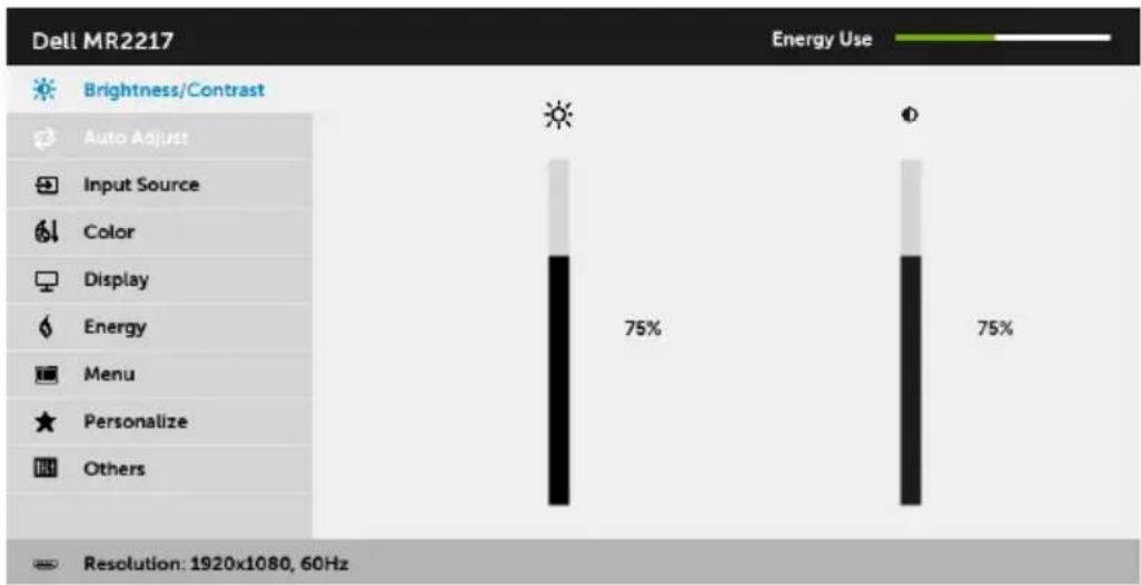
bar
Dell MR2217 Energy Use | Category | Value (%) | |---|---| | Light Source | 75 | | Dark Source | 75 | Resolution: 1920x1080, 60Hz
or
Main Menu for digital (DP) input
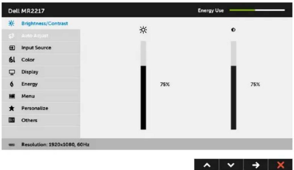
bar
Dell MR2217 Energy Use | Category | Value (%) | |---|---| | Brightness/Contrast | | | Auto Adjust | | | Input Source | | | Color | | | Display | | | Energy | | | Menu | | | Personalize | | | Others | | Resolution: 1920x1080, 60Hz
NOTE: Auto Adjust is only available when you use the analog (VGA) connector.
2 Pr ess the ▲ and ▼ buttons to move between the setting options. As you move from one icon to another, the option name is highlighted. See the following table for a complete list of all the options available for the monitor.
3 Pr ess the button once to activate the highlighted option.
4 Press ▲ and ▼ button to select the desired parameter.
5 Select the button to return to the main menu.
| Icon Menu and Submenus | Description | |
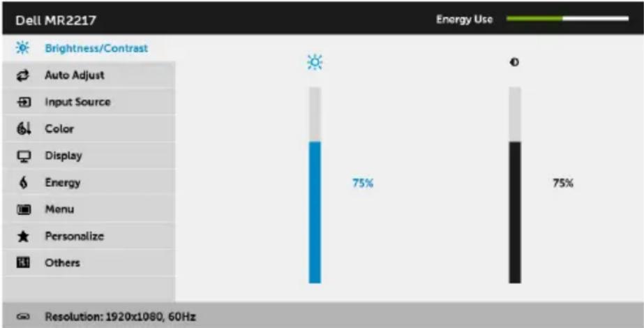
 | Brightness/ Contrast | Use this menu to activate Brightness/Contrast adjustment. |
 | ||
 | ||
| NOTE: Press swtich between the options. | ||
| Brightness | Brightness adjusts the luminance of the backlight. | |
| Press the button to increase the brightness and press the button to decrease the brightness (min. 0 / max. 100). | ||
| Contrast | Adjust the Brightness first, and then adjust the Contrast only if further adjustment is necessary. | |
| Press the button to increase the contrast and press the button to decrease the contrast (min. 0 / max. 100). | ||
| The Contrast function adjusts the degree of difference between darkness and lightness on the monitor screen. | ||
| NOTE: Contrast is grayed out in DICOM mode to maintain grayscale accuracy. | ||

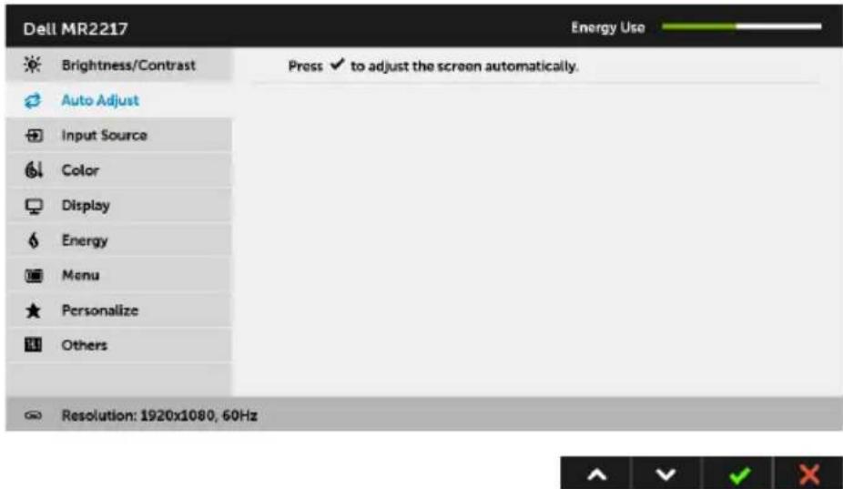
Auto Adjust
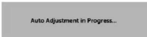
Even though your computer recognizes your monitor on startup, the Auto Adjustment function optimizes the display settings for use with your particular setup.
text_image
Dell MR2217 Energy Use Brightness/Contrast Press ✓ to adjust the screen automatically. Auto Adjust Input Source Color Display Energy Menu Personalize Others Resolution: 1920x1080, 60HzAuto Adjustment allows the monitor to self-adjust to the incoming video signal. After using Auto Adjustment, you can further tune your monitor by using the Pixel Clock (Coarse) and Phase (Fine) controls under Display settings.
text_image
Auto Adjustment in Progress...NOTE: In most cases, Auto Adjust produces the best image for your configuration.
NOTE: Auto Adjust option is only available when you are using the analog (VGA) connector.

Input Source
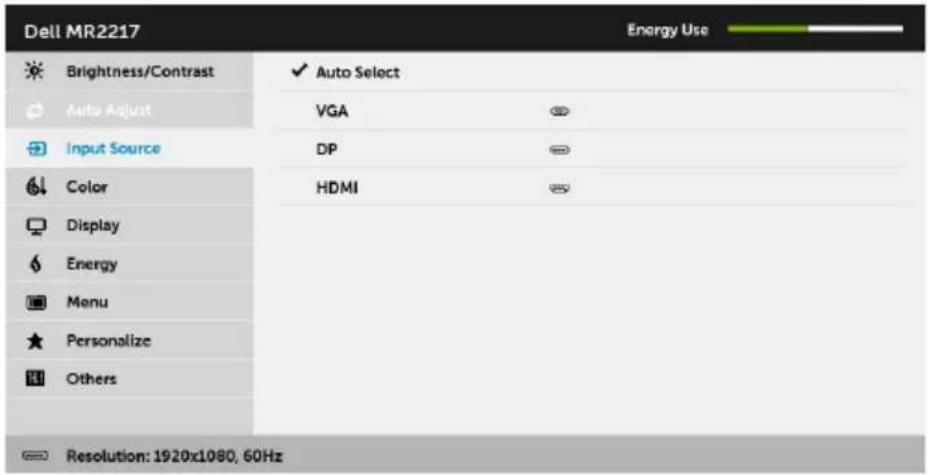
Use the Input Source menu to select between the different video signals that may be connected to your monitor.
text_image
Dell MR2217 Energy Use Brightness/Contrast ✓ Auto Select Auto Adjust VGA Input Source DP Color HDMI Display Energy Menu Personalize Others Resolution: 1920x1080, 60Hz
| Auto Select | Press → to select Auto Select, the monitor scans for available input sources. |
| VGA | Select the VGA input when you are using the analog (VGA) connector. Press → to select the VGA input source. |
| DP | Select the DP input when you are using the DisplayPort (DP) connector. Press → to select the DisplayPort input source. |
| HDMI | Select the HDMI input when you are using the HDMI connector. Press → to select the HDMI input source. |

text_image
Dell MR2217 Brightness/Contrast Auto Adjust Input Source Color Display Energy Menu Personalize Others Reset Color Energy Use DICOM RGB Resolution: 1920x1080, 60Hz
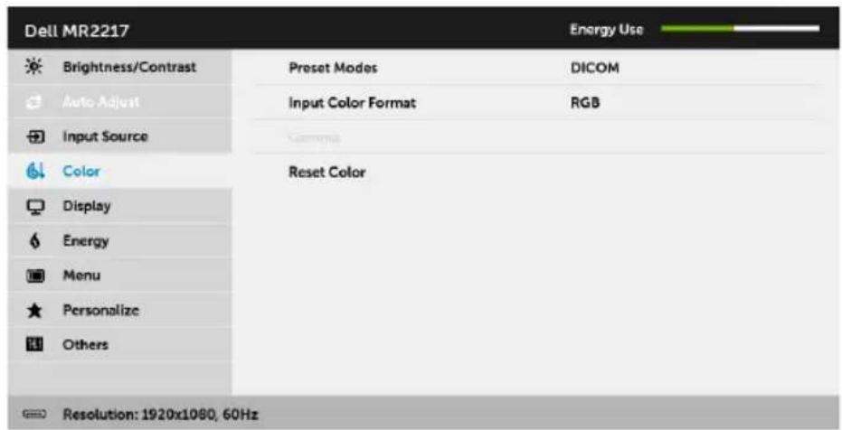
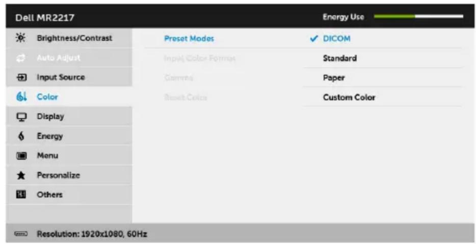
Preset Modes
When you select Preset Modes, you can choose DICOM, Standard, Paper, or Custom Color from the list.
- DICOMoviles consistent luminance uniformity and on diverse displays with consistent methodology. This is the default preset mode.
- Stand boards the monitor's default color settings.
- Paper : Loads brightness sharpness settings ideal for viewing text. Blend the text background to simulate paper media without affecting color images. Applies to RGB input format only.
- Custom Color: Allows you to manually adjust the color settings.
Press the ▲ and ▼ buttons to adjust the three colors (R, G, B) values and create your own preset color mode.
text_image
Dell MR2217 Energy Use Brightness/Contrast Preset Modes ✓ DICOM Auto Adjust Input Color Format Standard Input Source Gamma Paper Color Reset Color Custom Color Display Energy Menu Personalize Others Resolution: 1920x1080, 60Hz
| Input Color Format | Allows you to set the video input mode to:RGB: Select this option if your monitor is connected to a computer (or DVD player) using the DP or HDMI cable.YPbPr: Select this option if your DVD player supports only YPbPr output. |
| Gamma | Allows you to set the Gamma to PC or MAC.NOTE: This option is not available when the Preset Modes is DICOM. |
| Reset Color | Reset your monitor color settings to the factory settings. |

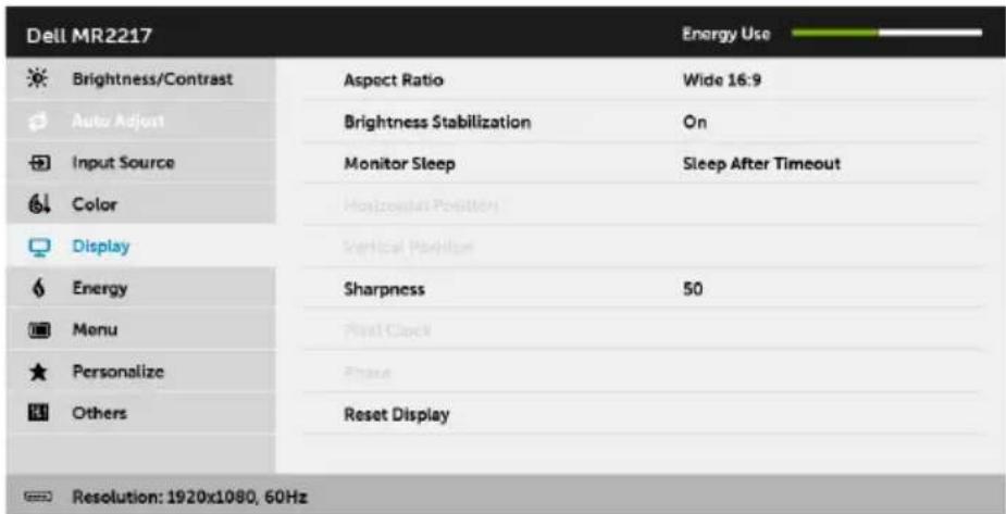
Display
Use Display to adjust image.
text_image
Dell MR2217 Brightness/Contrast Aspect Ratio Wide 16:9 Auto Adjust Brightness Stabilization On Input Source Monitor Sleep Sleep After Timeout Color Horizontal Position Display Vertical Position Energy Sharpness 50 Menu Final Clock Personalize Phase Others Reset Display Resolution: 1920x1080, 60Hz
| Aspect Ratio | Adjusts the image ratio to Wide 16:9, 4:3, or 5:4. |
| Brightness Stabilization | Activating this feature to maintain stable brightness level and shorten cold startup time.NOTE: This option is only available when the Preset Modes is DICOM or Standard. |
| Monitor Sleep | Allows you to let the monitor turn off automatically or stay on when your computer goes into sleep mode. When Sleep After Timeout is selected, the monitor goes to sleep as the system sleeps; when Never is selected, you may prevent the screen from going off as the system sleeps for speedy display recovery from PC wake up. |
| Horizontal Position | Use ▲ or ▼ to adjust the image left or right. Minimum is '0' (-). Maximum is '100' (+). |
| Vertical Position | Use ▲ or ▼ to adjust the image up or down. Minimum is '0' (-). Maximum is '100' (+).NOTE: Horizontal Position and Vertical Position adjustments are only available for "VGA" input. |
| Sharpness | This feature can make the image look sharper or softer. Use ▲ to adjust the sharpness from '0' to '100'. |
| Pixel Clock | The Phase and Pixel Clock adjustments allow you to adjust your monitor to your preference.Use ▲ or ▼ adjust for best image quality. |
| Phase | If satisfactory results are not obtained using the Phase adjustment, use the Pixel Clock (coarse) adjustment and then use Phase (fine), again.NOTE: Pixel Clock and Phase adjustments are only available for "VGA" input. |
| Reset Display | Select this option to restore default display settings. |

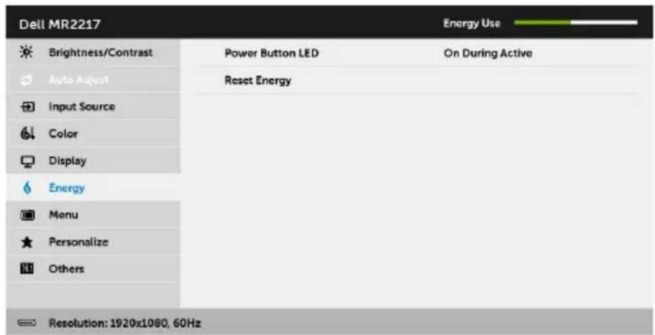
Energy
text_image
Dell MR2217 Brightness/Contrast Power Button LED On During Active Auto Adjust Reset Energy Input Source Color Display Energy Menu Personalize Others Resolution: 1920x1080, 60Hz
| Power Button LED | Allows you to set the power LED indicator On or Off to save energy. | |
| Reset Energy | Select this option to restore default Energy settings. | |
 | Menu | Select this option to adjust the settings of the OSD, such as, the languages of the OSD, the amount of time the menu remains on screen, and so on. |
| Dell MR2217 | Energy Use | ||
| Brightness/Contrast | Language | English | |
| Auto Adjust | Rotation | ||
| Input Source | Transparency | 20 | |
| Color | Timer | 20 s | |
| Display | Lock | Unlock | |
| Energy | Reset Menu | ||
| Menu | |||
| Personalize | |||
| Others | |||
| Resolution: 1920x1080, 60Hz | |||

| Language | Language options set the OSD display to one of the three languages (English, Spanish, and French). |
| Rotation | Rotates the OSD by 90 degrees counter-clockwise. You can adjust the menu according to your Display Rotation. |
| Transparency | Select this option to change the menu transparency by pressing the ▲ and ▼ttons (min. 0 / max. 100). |
| Timer | Allows you to set the time for which the OSD remains active after you press a button on the monitor.Use ▲ or ▼adjust the slider in 1 second increments, from 5 to 60 seconds. |
| Lock | Controls user access to adjustments. When Lock is selected, no user adjustments are allowed. All buttons are locked.NOTE:Unlock function- Only hard unlock (press and hold the button above the power button for 6 seconds).Lock function - Either soft lock (through the OSD menu) or hard lock (press and hold the button above the power button for 6 seconds). | |
| Reset Menu | Reset all OSD settings to the factory preset values. | |
 | Personalize | Users can choose a feature from Preset Modes, Brightness/Contrast, Auto Adjust, Input Source, Aspect Ratio, or Rotation and set it as a shortcut key.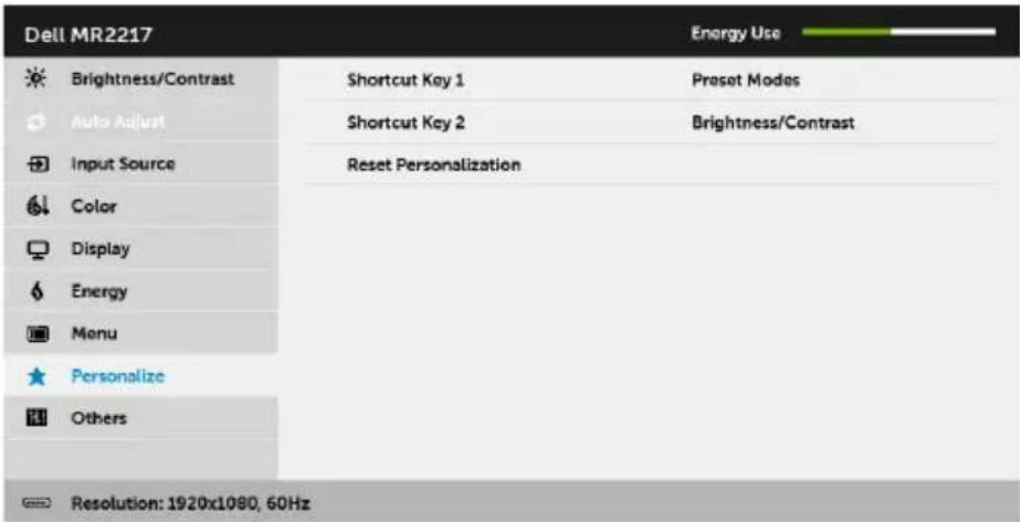  |
| Reset Personalization | Restores shortcut keys to factory defaults. |

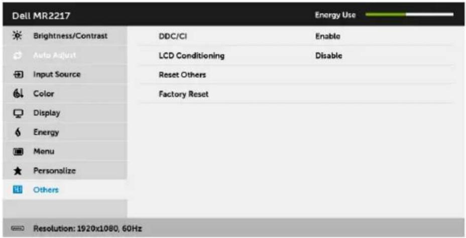
Others
Select this option to adjust the OSD settings, such as the DDC/CI, LCD Conditioning, and so on.
text_image
Dell MR2217 Brightness/Contrast Auto Adjust Input Source Color Display Energy Menu Personalize Others DDC/CI LCD Conditioning Reset Others Factory Reset Enable Disable Resolution: 1920x1080, 60Hz
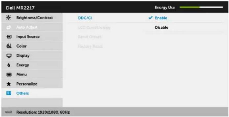
DDC/CI
DDC/CI (Display Data Channel/Command Interface) allows your monitor parameters (brightness, color balance, and etc.) to be adjustable via the software on your computer.
You can disable this feature by selecting Disable.
Enable this feature for best user experience and optimum performance of your monitor.
text_image
Dell MR2217 Energy Use Brightness/Contrast DDC/CI Enable Auto Adjust SCD Complating Disable Input Source Reset Other Color Factory Reset Display Energy Menu Personalize Others Resolution: 1920x1080, 60Hz
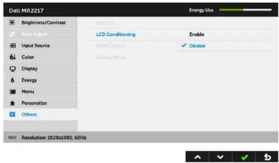
LCD Conditioning
Helps reduce minor cases of image retention. Depending on the degree of image retention, the program may take some time to run. You can enable this feature by selecting Enable.
text_image
Dell MR2217 Energy Use Brightness/Contrast Auto Adjust Input Source Color Display Energy Menu Personalize Others LCD Conditioning Enable Reset Others ✓ Disable Factory Reset Resolution: 1920x1080, 60HzReset Others
Reset all settings under the Others menu to the factory preset values.
Factory Reset
Reset all settings to the factory preset values.

NOTE: This monitor has a built-in feature to automatically calibrate the brightness to compensate for LED aging.
OSD Warning Messages
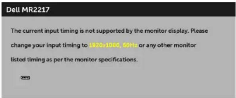
When the monitor does not support a particular resolution mode, you will see the following message:
text_image
Dell MR2217 The current input timing is not supported by the monitor display. Please change your input timing to 1920x1080, 50Hz or any other monitor listed timing as per the monitor specifications.This means that the monitor cannot synchronize with the signal that it is receiving from the computer. See Monitor Specifications for the Horizontal and Vertical frequency ranges addressable by this monitor. Recommended mode is 1920 x 1080.
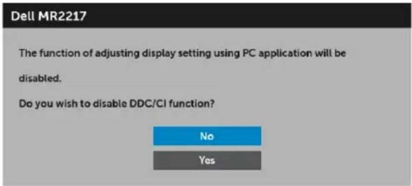
You will see the following message before the DDC/CI function is disabled:
text_image
Dell MR2217 The function of adjusting display setting using PC application will be disabled. Do you wish to disable DDC/CI function? No YesWhen the monitor enters the Power Save mode, the following message appears:
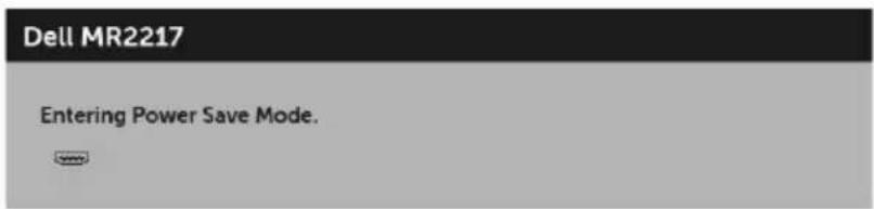
text_image
Dell MR2217 Entering Power Save Mode.Activate the computer and wake up the monitor to gain access to the OSD.
If you press any button other than the power button, the following message will appear depending on the selected input:
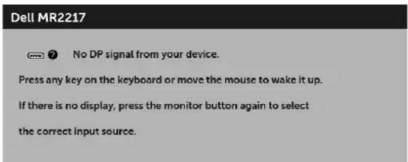
text_image
Dell MR2217 No DP signal from your device. Press any key on the keyboard or move the mouse to wake it up. If there is no display, press the monitor button again to select the correct input source.
NOTE: The message may be slightly different according to the connected input signal.
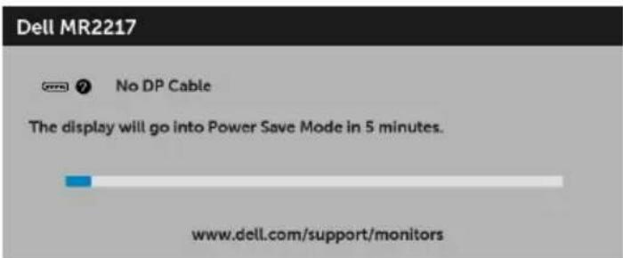
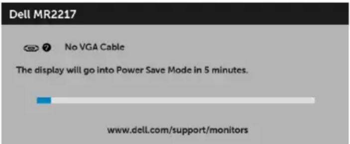
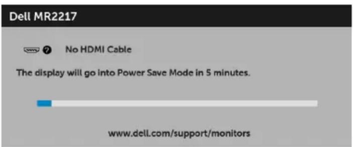
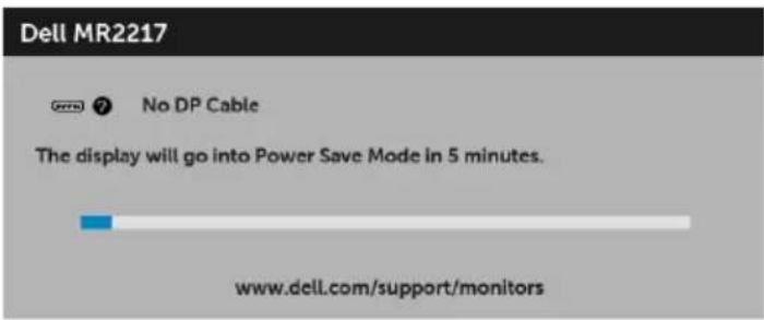
If either VGA, HDMI, or DP input is selected and the corresponding cable is not connected, a floating dialog box as shown below appears.
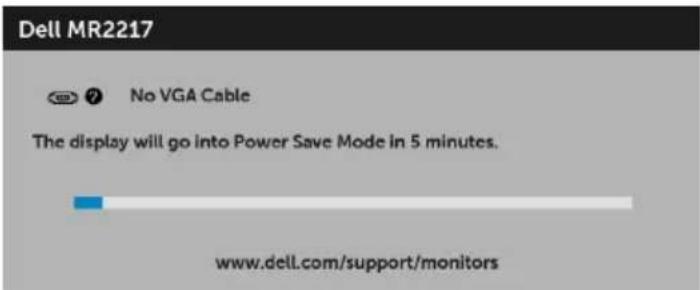
text_image
Dell MR2217 No VGA Cable The display will go into Power Save Mode in 5 minutes. www.dell.com/support/monitorsor
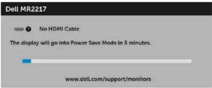
text_image
Dell MR2217 No HDMI Cable The display will go into Power Save Mode in 5 minutes. www.dell.com/support/monitorsor
text_image
Dell MR2217 No DP Cable The display will go into Power Save Mode in 5 minutes. www.dell.com/support/monitorsSee Troubleshooting for more information.
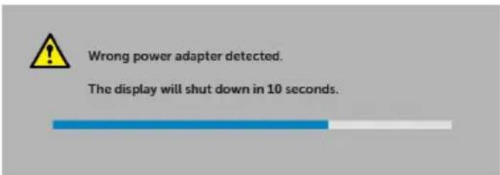
Use only the supplied power adapter to connect to this monitor and AC mains. Using adapter other than the one supplied may cause malfunction and damage to the monitor, the following error message will appear:
text_image
Wrong power adapter detected. The display will shut down in 10 seconds.Setting the Maximum Resolution
To set the maximum resolution for the monitor:
In Windows ^® 7, Windows ^® 8, and Windows ^® 8.1:
1 For Windows ^ 8 and Windows ^ 8.1 only, select the Desktop tile to switch to classic desktop.
2 Right-click on the desktop and click Screen Resolution.
3 Click the Dropdown list of the Screen Resolution and select 1920 x 1080.
4 Click OK.
In Windows ^® 10:
1 Right-click on the desktop and click Display settings.
2 Click Advanced display settings.
3 Click the dropdown list of Resolution and select 1920 x 1080.
4 Click Apply.
If you do not see 1920 x 1080 as an option, you may need to update your graphics driver. Depending on your computer, complete one of the following procedures:
If you have a Dell desktop or portable computer:
- Go to http://www.dell.com/support, enter your service tag, and download the latest driver for your graphics card.
If you are using a non-Dell computer (portable or desktop):
- Go to the support site for your computer and download the latest graphic drivers.
- Go to your graphics card website and download the latest graphic drivers.
Using the Tilt, Swivel, and Vertical Extension

NOTE: This is applicable for a monitor with a stand. When any other stand is bought, please refer to the respective stand setup guide for set up instructions.
Tilt, Swivel
With the stand attached to the monitor, you can tilt and swivel the monitor for the most comfortable viewing angle.
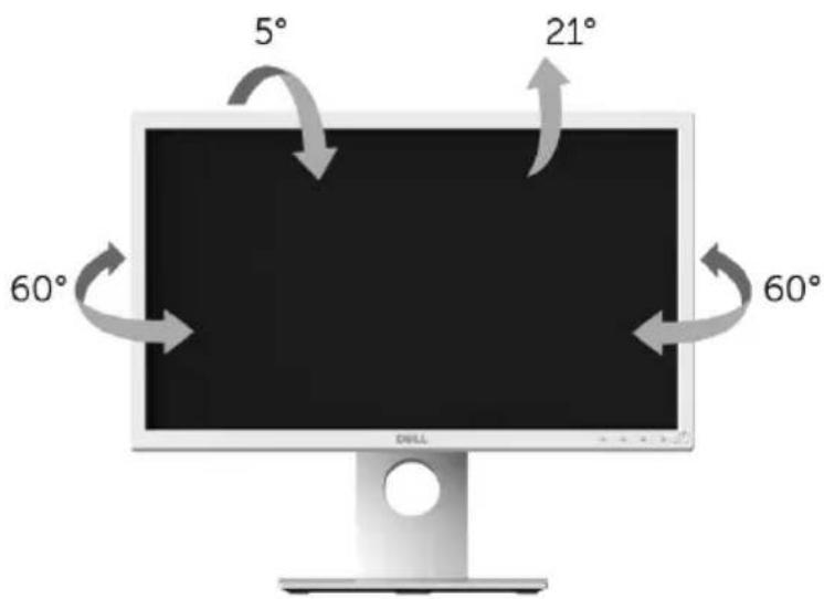
text_image
5° 21° 60° 60°
NOTE: The stand is detached when the monitor is shipped from the factory.
Vertical Extension

NOTE: The stand extends vertically up to 130 mm. The figure below illustrates how to extend the stand vertically.
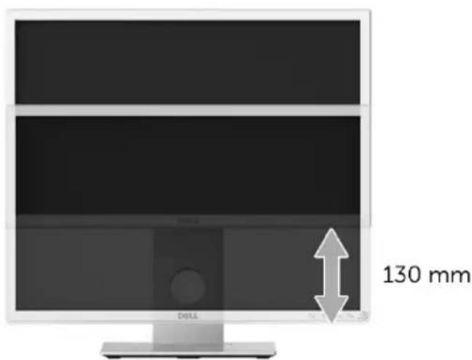
text_image
130 mm DOLLRotating the Monitor
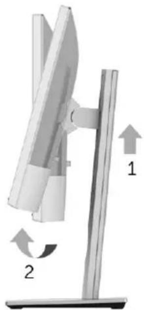
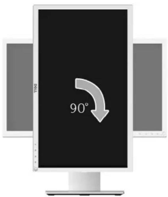
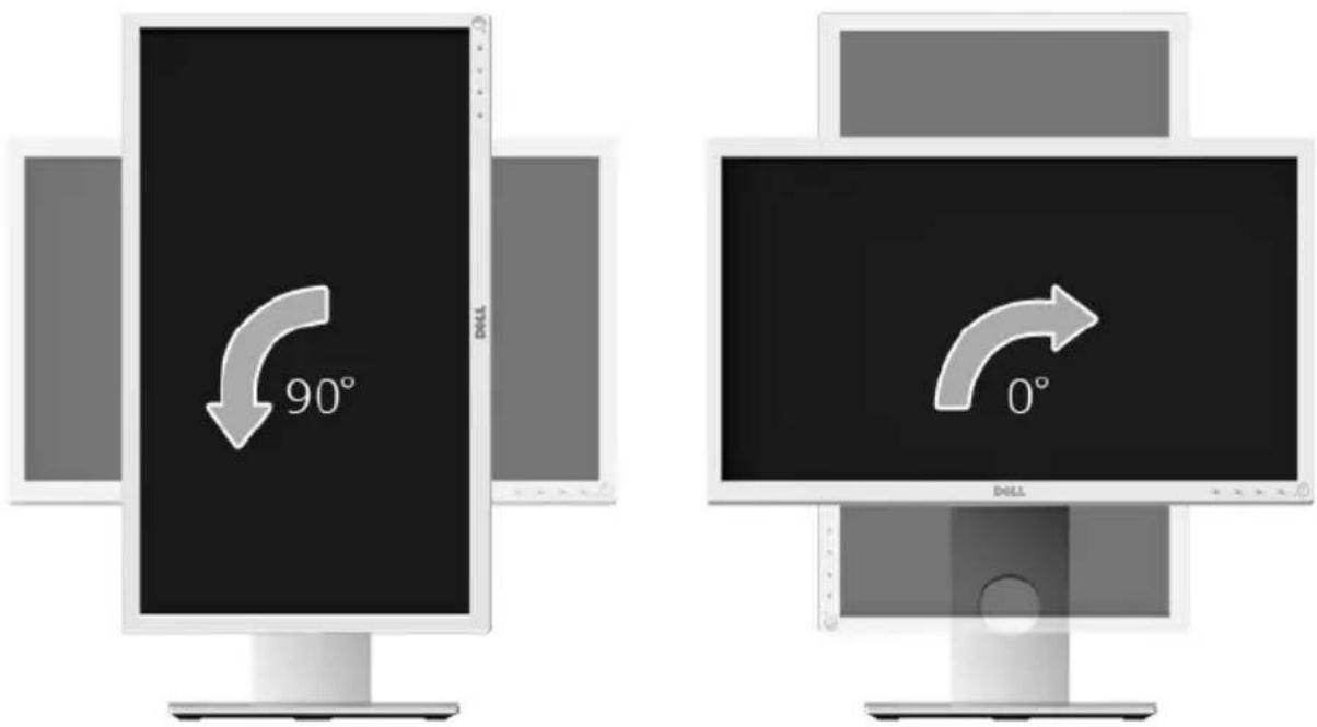
Before you rotate the monitor, your monitor should be fully vertically extended (Vertical Extension) and fully tilted up to avoid hitting the bottom edge of the monitor.
natural_image
Diagram of a vertical stand with two curved arrows indicating rotational motion, labeled 1 and 2 (no text or symbols on the diagram itself)Rotate clockwise
text_image
90°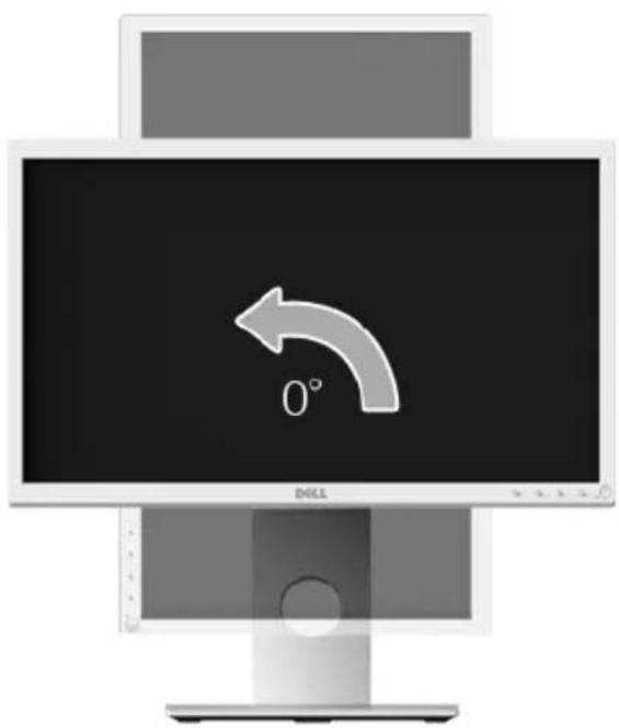
natural_image
Computer monitor with a curved arrow icon pointing to the left side (no text or symbols on the screen)Rotate counterclockwise
text_image
90° DILL 0°
NOTE: To use the Display Rotation function (Landscape versus Portrait view) with your Dell computer, you require an updated graphics driver that is not included with this monitor. To download the graphics driver, go to www.dell.com/support and see the Download section for Video Drivers for latest driver updates.

NOTE: When in the Portrait View Mode, you may experience performance degradation in graphic-intensive applications (3D Gaming and etc.).
Adjusting the Rotation Display Settings of Your System
After you have rotated your monitor, you need to complete the procedure below to adjust the Rotation Display Settings of your system.

NOTE: If you are using the monitor with a non-Dell computer, you need to go the graphics driver website or your computer manufacturer website for information on rotating the 'contents' on your display.
To adjust the Rotation Display Settings:
1 Right-click on the desktop and click Properties.
2 Select the Settings tab and click Advanced.
3 If you have an ATI graphics card, select the Rotation tab and set the preferred rotation.
4 If you have an nVidia graphics card, click the nVidia tab, in the left-hand column select NVRotate, and then select the preferred rotation.
5 If you have an Intel ^ graphics card, select the Intel graphics tab, click Graphic Properties, select the Rotation tab, and then set the preferred rotation.

NOTE: If you do not see the rotation option or it is not working correctly, go to www.dell.com/support and download the latest driver for your graphics card.

WARNING: Before you begin any of the procedures in this section, follow the Safety Instructions.
Self-Test
Your monitor provides a self-test feature that allows you to check whether your monitor is functioning properly. If your monitor and computer are properly connected but the monitor screen remains dark, run the monitor self-test by performing the following steps:
1 T urn off both your computer and the monitor.
2 Unp lug the video cable from the back of the computer. To ensure proper Self-Test operation, remove all digital cables from the back of computer.
3 Turn on the monitor.
The floating dialog box should appear on-screen (against a black background), if the monitor cannot sense a video signal and is working correctly. While in self-test mode, the power LED remains green. Also, depending upon the selected input, one of the dialogs shown below will continuously scroll through the screen.
text_image
Dell MR2217 No VGA Cable The display will go into Power Save Mode in 5 minutes. www.dell.com/support/monitorsor
text_image
Dell MR2217 No HDMI Cable The display will go into Power Save Mode in 5 minutes. www.dell.com/support/monitorsor
text_image
Dell MR2217 No DP Cable The display will go into Power Save Mode in 5 minutes. www.dell.com/support/monitors4 This box also appears during normal system operation, if the video cable becomes disconnected or damaged.
5 Turn Off your monitor and reconnect the video cable; then turn On both your computer and the monitor.
If your monitor screen remains blank after you use the previous procedure, check your video controller and computer, because your monitor is functioning properly.
Built-in Diagnostics
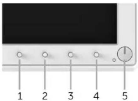
Your monitor has a built-in diagnostic tool that helps you determine if the screen abnormality you are experiencing is an inherent problem with your monitor, or with your computer and video card.

NOTE: You can run the built-in diagnostics only when the video cable is unplugged and the monitor is in self-test mode.
text_image
1 2 3 4 5To run the built-in diagnostics:
1 Ensur e that the screen is clean (no dust particles on the surface of the screen).
2 Unp lug the video cable(s) from the back of the computer or monitor. The monitor then goes into the self-test mode.
3 Press and hold Button 1 and Button 4 on the front panel simultaneously for 2 seconds. A gray screen appears.
4 Care fully inspect the screen for abnormalities.
5 Press Button 4 on the front panel again. The color of the screen changes to red.
6 Inspect the display for any abnormalities.
7 Repeat steps 5 and 6 to inspect the display in red, green, blue, black, white and text screens.
The test is complete when the text screen appears. To exit, press Button 4 again.
If you do not detect any screen abnormalities upon using the built-in diagnostic tool, the monitor is functioning properly. Check the video card and computer.
Common Problems
The following table contains general information about common monitor problems you might encounter and the possible solutions:
| Common Symptoms | What You Experience | Possible Solutions |
| No Video/Power LED off | No picture | ·Ensure that the video cable connecting the monitor and the computer is properly connected and secure.·Verify that the power outlet is functioning properly using any other electrical equipment.·Ensure that the power button is pressed fully.·Ensure that the correct input source is selected in the Input Source menu. |
| No Video/Power LED on | No picture or no brightness | ·Increase brightness & contrast controls via OSD.·Perform monitor self-test feature check.·Check for bent or broken pins in the video cable connector.·Run the built-in diagnostics.·Ensure that the correct input source is selected in the Input Source menu. |
| Poor Focus Picture is fuzzy, blurry, or ghosting | ·Perform Auto Adjust via OSD.·Adjust the Phase and Pixel Clock controls via OSD.·Eliminate video extension cables.·Reset the monitor to factory settings.·Change the video resolution to the correct aspect ratio. | |
| Shaky/Jittery Video | Wavy picture or fine movement | ·Perform Auto Adjust via OSD.·Adjust the Phase and Pixel Clock controls via OSD.·Reset the monitor to factory settings.·Check environmental factors.·Relocate the monitor and test in another room. |
| Missing Pixels LCD screen has spots | ·Cycle power On-Off.·Pixel that is permanently Off is a natural defect that can occur in LCD technology.·For more information on Dell Monitor Quality and Pixel Policy, see Dell Support site at: http://www.dell.com/support/monitors. | |
| Stuck-on Pixels LCD screen has bright spots | ·Cycle power On-Off.·Pixel that is permanently off is a natural defect that can occur in LCD technology.·For more information on Dell Monitor Quality and Pixel Policy, see Dell Support site at: http://www.dell.com/support/monitors. | |
| BrightnessProblems | Picture too dimor too bright | Reset the monitor to factory settings.PerformAuto Adjustvia OSD.Adjust brightness & contrast controls via OSD. |
| GeometricDistortion | Screen notcenteredcorrectly | Reset the monitor to factory settings.PerformAuto Adjustvia OSD.Adjust horizontal & vertical controls via OSD.NOTE:When using HDMI/DisplayPort input, the positioning adjustments are not available. |
| Horizontal/Vertical Lines | Screen has oneor more lines | Reset the monitor to factory settings.PerformAuto Adjustvia OSD.Adjust thePhaseandPixel Clockcontrols via OSD.Perform monitor self-test feature check and determine if these lines are also in self-test mode.Check for bent or broken pins in the video cable connector.Run the built-in diagnostics.NOTE:When using HDMI/DisplayPort input, thePixel ClockandPhaseadjustments are not available. |
| SynchronizationProblems | Screen isscrambled orappears torn | Reset the monitor to factory settings.PerformAuto Adjustvia OSD.Adjust thePhaseandPixel Clockcontrols via OSD.Perform monitor self-test feature check to determine if the scrambled screen appears in self-test mode.Check for bent or broken pins in the video cable connector.Restart the computer in thesafe mode. |
| Safety RelatedIssues | Visible signs ofsmoke or sparks | Do not perform any troubleshooting steps.Contact Dell immediately. |
| IntermittentProblems | Monitormalfunctions on& off | Ensure that the video cable connecting the monitor to the computer is connected properly and is secure.Reset the monitor to factory settings.Perform monitor self-test feature check to determine if the intermittent problem occurs in self-test mode. |
| Missing Color Picture missingcolor | Perform monitor self-test feature check.Ensure that the video cable connecting the monitor to the computer is connected properly and is secure.Check for bent or broken pins in the video cable connector. | |
| Wrong Color Picture color notgood | Change the settings of thePreset Modesin theColormenu OSD depending on the application.Adjust R/G/B value underCustom ColorinColormenu OSD.Change theInput Color Formatto PC RGB or YPbPr in theColormenu OSD.Run the built-in diagnostics. | |
| Image retention from a static image left on the monitor for a long period of time | Faint shadow from the static image displayed appears on the screen | ·Use the Power Management feature to turn off the monitor at all times when not in use (for more information, see Power Management Modes).·Alter natively, use a dynamically changing screensaver. |
Product Specific Problems
| Specific Symptoms | What You Experience | Possible Solutions |
| Screen image is too small | Image is centered on screen, but does not fill entire viewing area | Check the Aspect Ratio setting in the Display menu OSD. Reset the monitor to factory settings. |
| Cannot adjust the monitor with the buttons on the front panel | OSD does not appear on the screen | Turn Off the monitor, unplug the power cord, plug it back, and then turn On the monitor.Check whether the OSD menu is locked. If yes, press and hold the button above the Power button for 6 seconds to unlock (for more information, see Lock). |
| No Input Signal when user controls are pressed | No picture, the LED light is breathing amber | Check the signal source. Ensure the computer is not in the power saving mode by moving the mouse or pressing any key on the keyboard.Check whether the signal cable is plugged in properly. Replug the signal cable if necessary. Reset the computer or video player. |
| The picture does not fill the entire screen | The picture cannot fill the height or width of the screen | Due to different video formats (aspect ratio) of DVDs, the monitor may display in full screen.Run the built-in diagnostics. |

NOTE: When choosing HDMI/DP mode, the Auto Adjust function will not be available.
Universal Serial Bus (USB) Specific Problems
| Specific Symptoms | What You Experience | Possible Solutions |
| USB interface is not working | USB peripherals are not working | Check that your monitor is turned On.Reconnect the up stream cable to your computer.Reconnect the USB p eripherals (downstream connector).Switch Off and then turn On the monitor again.Reboot the computer.Some USB devices like external portable HDD require higher electric current; connect the device directly to the computer system. |
| High Speed USB 2.0 interface is slow | High Speed USB 2.0 peripherals working slowly or not working at all | Check that your computer is USB 2.0-capable.Some computers have both USB 2.0 and USB 1.1 ports.Ensure that the correct USB port is used.Reconnect the up stream cable to your computer.Reconnect the USB p eripherals (downstream connector).Reboot the computer. |
Contact Dell
For customers in the United States, call 800-WWW-DELL (800-999-3355).

NOTE: If you do not have an active Internet connection, you can find contact information on your purchase invoice, packing slip, bill, or Dell product catalog.
Dell provides several online and telephone-based support and service options. Availability varies by country and product, and some services may not be available in your area.
• Online technical assistance — www.dell.com/support/monitors
- Contacting Dell — www.dell.com/contactdell
Setting Up Your Monitor
Setting the display resolution
For maximum display performance with Microsoft ^® Windows ^® operating systems, set the display resolution to 1920 x 1080 pixels by performing the following steps:
In Windows ^® 7, Windows ^® 8, and Windows ^® 8.1:
1 For Windows ^ 8 and Windows ^ 8.1 only, select the Desktop tile to switch to classic desktop.
2 Right-click on the desktop and click Screen Resolution.
3 Click the Dropdown list of the Screen Resolution and select 1920 x 1080.
4 Click OK.
In Windows ^® 10:
1 Right-click on the desktop and click Display settings.
2 Click Advanced display settings.
3 Click the dropdown list of Resolution and select 1920 x 1080.
4 Click Apply.
If you do not see the recommended resolution as an option, you may need to update your graphics driver. Please choose the scenario below that best describes the computer system you are using, and follow the given steps.
If you have a Dell™ desktop or a Dell™ portable computer with internet access
1 Go to www.dell.com/support, enter your service tag, and download the latest driver for your graphics card.
2 After installing the drivers for your graphics adapter, attempt to set the resolution to 1920 x 1080 again.

NOTE: If you are unable to set the resolution to 1920 x 1080, please contact Dell™ to inquire about a graphics adapter that supports these resolutions.
If you have a non Dell™ desktop, portable computer, or graphics card
In Windows ^® 7, Windows ^® 8, and Windows ^® 8.1:
1 For Windows ^® 8 and Windows ^® 8.1 only, select the Desktop tile to switch to classic desktop.
2 Right-click on the desktop and click Personalization.
3 Click Change Display Settings.
4 Click Advanced Settings.
5 Identify your graphics controller supplier from the description at the top of the window (e.g. NVIDIA, ATI, Intel etc.).
6 Refer to the graphic card provider website for updated driver (for example, http://www.ATI.com OR http://www.NVIDIA.com).
7 After installing the drivers for your graphics adapter, attempt to set the resolution to 1920 x 1080 again.
In Windows ^® 10:
1 Right-click on the desktop and click Display settings.
2 Click Advanced display settings.
3 Click the dropdown list of Resolution and select 1920 x 1080.
4 Identify your graphics controller supplier from the description at the top of the window (e.g. NVIDIA, ATI, Intel etc.).
5 Refer to the graphic card provider website for updated driver (for example, http://www.ATI.com OR http://www.NVIDIA.com).
6 After installing the drivers for your graphics adapter, attempt to set the resolution to 1920 x 1080 again.

NOTE: If you are unable to set the recommended resolution, please contact the manufacturer of your computer or consider purchasing a graphics adapter that will support the video resolution.