
Inspiron 7000 - Laptop DELL - Free user manual and instructions
Find the device manual for free Inspiron 7000 DELL in PDF.


| Product Type | Laptop |
| Brand | Dell |
| Model | Inspiron 7000 |
| Processor | Intel Mobile Pentium II with MMX technology, 266 MHz or 300 MHz |
| Memory | Minimum 32 MB SDRAM, expandable up to 192 MB via two SODIMM slots |
| Display | 13.3-inch or 14.1-inch active-matrix XGA TFT, 1024x768 pixels |
| Graphics | ATI Rage LT Pro 64-bit AGP 2X, 4 MB or 8 MB SGRAM |
| Storage | Hard-disk drive (multiple capacities available), combo CD-ROM/DVD-ROM and floppy drive module |
| Audio | Built-in microphone, stereo speakers, headphone/line-out/line-in jacks, Sound Blaster Pro compatible |
| Dimensions | Width: 318 mm (12.52 in), Depth: 254 mm (10 in), Height: 54 mm (2.1 in) |
| Weight | Approximately 3.74 kg (8.25 lb) with 13.3-in display; 3.8 kg (8.37 lb) with 14.1-in display |
| Battery | 65 WH smart lithium-ion (12 cells), main and optional secondary battery |
| AC Adapter | Input: 90-264 VAC, 47-63 Hz, Output: 20 VDC, 70 W |
| Ports | Serial, parallel, VGA, S-Video TV-out, USB, PS/2, infrared (IrDA 1.1), audio jacks, docking connector |
| Expansion Slots | Two Type I/II or one Type III PC Card slot, one options bay for combo module or secondary battery |
| Power Management | Smart CPU Mode, Standby and Suspend timeouts, Save-to-disk suspend mode |
| Operating System | Supports MS-DOS and Windows (likely Windows 98/NT) |
| Security | Kensington lock slot, password protection via Setup program |
| Environmental | Operating temp: 5° to 35°C, Storage temp: -20° to 50°C, Humidity: 10% to 90% noncondensing |
| Spare Parts Availability | Extensive list of factory repair parts and customer replaceable units (CRUs) including keyboard, battery, hard drive, memory, AC adapter, etc. |
| Repairability | Detailed service manual with step-by-step procedures for disassembly and replacement of major components |
Frequently Asked Questions - Inspiron 7000 DELL
User questions about Inspiron 7000 DELL
0 question about this device. Answer the ones you know or ask your own.
Ask a new question about this device
Download the instructions for your Laptop in PDF format for free! Find your manual Inspiron 7000 - DELL and take your electronic device back in hand. On this page are published all the documents necessary for the use of your device. Inspiron 7000 by DELL.
USER MANUAL Inspiron 7000 DELL
Information in this manual is subject to change without notice.
© 1998 Dell Computer Corporation. All rights reserved.
Reproduction in any manner whatsoever without the written permission of Dell Computer Corporation is strictly forbidden.
Trademarks used in this text: Dell and the DELL logo are registered trademarks and Inspiron is a trademark of Dell Computer Corporation; MS-DOS is a registered trademark of Microsoft Corporation; Intel and Pentium are registered trademarks and MMX is a trademark of Intel Corporation; IBM is a registered trademark of International Business Machines Corporation.
Other trademarks and trade names may be used in this document to refer to either the entities claiming the marks and names or their products. Dell Computer Corporation disclaims any proprietary interest in trademarks and trade names other than its own.
August 1998 P/N 6086C
natural_image
Illustration of a closed book with a keyboard and a small object on top (no text or symbols)Contents
Chapter 1 System Overview....1-1
System Features 1-1
Physical Description....1-2
Status Display 1-3
Battery Charge Gauge 1-4
System Power 1-5
Power Management Mode 1-5
Smart CPU Mode....1-6
Standby Time-Out 1-6
Suspend Time-Out. 1-6
Suspend Mode 1-7
Interrupt Assignments....1-7
Technical Specifications....1-8
Chapter 2 Initial Procedures. . . . . . . . . . . . . . . . . . . . . . . . . . . . . . . . . . . . . . . . . . . . . . . . . . . . . . . . . . . . . . . . . . . . . 2-1
Initial User Contact 2-1
Visual Inspection 2-2
Observing the Boot Routine 2-4
Eliminating Resource Conflicts 2-5
Getting Help. 2-5
Chapter 3Beep Codes and Error Messages....3-1
POST Beep Codes....3-1
System Error Messages 3-2
Running the Dell Diagnostics....3-4
Chapter 4Removing and Replacing Parts....4-1
Recommended Tools. 4-1
Screw Identification and Tightening 4-2
Precautionary Measures 4-2
ZIF Connectors 4-8
Exploded View of Components and Assemblies....4-10
Factory Repair Parts and Assemblies 4-15
Hard-Disk Drive 4-28
Combo Module 4-29
General Disassembly.... 4-31
Keyboard 4-32
Thermal Shield and Internal Modem 4-34
Display Assembly and Components 4-36
Display Assembly 4-37
Front Bezel.... 4-38
13.3-Inch LCD Panel 4-39
13.3-Inch LCD Brackets and Carrier Tray.... 4-41
14.1-Inch LCD Panel, Brackets, and Carrier Tray.... 4-42
Palmrest Assembly and Components 4-44
MPEG-2 Card.... 4-45
Palmrest Assembly 4-46
IR Board.... 4-48
Hard-Disk Drive Heat Shield 4-49
Touch Pad Assembly 4-50
Speakers 4-52
Base Assembly and Components 4-53
PC Card Heat Sink 4-54
Heat Exchanger/Fan. 4-55
DC-DC Board 4-56
LVDS Board 4-57
Processor Board and Memory Module 4-58
Hinge Saddles 4-60
RJ-11 Card 4-61
System Board 4-62
PC Card Cage.... 4-63
Audio Card and Audio Thermal Shield 4-64
Latch Assembly 4-65
Figures
Figure 1-1. Front View 1-2
Figure 1-2. Back View 1-3
Figure 1-3. Indicator Panel above Keyboard 1-3
Figure 1-4. Indicator Panel on Front of Computer.... 1-4
Figure 1-5. Battery Charge Gauge.... 1-5
Figure 4-1. Computer Orientation 4-1
Figure 4-2. Screw Identification 4-2
Figure 4-3. AC Adapter Removal.... 4-3
Figure 4-4. Computer Removal From Inspiron Port Replicator II ..... 4-4
Figure 4-5. Main Battery Removal.... 4-4
Figure 4-6. PC Card Removal 4-5
Figure 4-7. Hard-Disk Drive Removal 4-6
Figure 4-8. Memory Module and Video Card Cover Removal. . . . . . . . 4-6
Figure 4-9. Memory Module Removal....4-7
Figure 4-10. Video Card Removal 4-7
Figure 4-11. Combo Module or Secondary Battery Removal ..... 4-8
Figure 4-12. Releasing a ZIF Connector ..... 4-9
Figure 4-13. Exploded View—Computer.... 4-10
Figure 4-14. Exploded View—13.3-Inch Display Assembly.....4-11
Figure 4-15. Exploded View—14.1-Inch Display Assembly.....4-12
Figure 4-16. Exploded View—Palmrest Assembly ..... 4-13
Figure 4-17. Exploded View—Base Assembly ..... 4-14
Figure 4-18. Hard-Disk Drive Disassembly ..... 4-28
Figure 4-19. CD-ROM/DVD-ROM Disassembly 4-29
Figure 4-20. Diskette Drive Disassembly ..... 4-30
Figure 4-21. Keyboard Removal 4-32
Figure 4-22. Thermal Shield Removal 4-34
Figure 4-23. Modem Removal....4-35
Figure 4-24. Display Assembly Removal....4-37
Figure 4-25. Front Bezel Removal 4-38
Figure 4-26. 13.3-Inch LCD Panel Removal. 4-39
Figure 4-27. 13.3-Inch LCD Brackets and Carrier Tray Removal ..... 4-41
Figure 4-28. 14.1-Inch LCD Panel Removal....4-42
Figure 4-29. MPEG-2 Card Removal 4-45
Figure 4-30. Palmrest Assembly Removal 4-46
Figure 4-31. IR Board Removal 4-48
Figure 4-32. Hard-Disk Drive Heat Shield Removal. 4-49
Figure 4-33. Touch Pad Assembly Removal 4-50
Figure 4-34. Speaker Removal 4-52
Figure 4-35. PC Card Heat Sink Removal 4-54
Figure 4-36. Heat Exchanger/Fan Removal 4-55
Figure 4-37. DC-DC Board Removal 4-56
Figure 4-38. LVDS Board Removal 4-57
Figure 4-39. Processor Board and Memory Module Removal ..... 4-58
Figure 4-40. Hinge Saddle Removal ..... 4-60
Figure 4-41. RJ-11 Card Removal 4-61
Figure 4-42. System Board Removal.... 4-62
Figure 4-43. PC Card Cage Removal ..... 4-63
Figure 4-44. Audio Card and Audio Thermal Shield Removal ..... 4-64
Figure 4-45. Latch Assembly Removal ..... 4-65
Tables
Table 1-1. Interrupt Assignments ..... 1-7
Table 1-2. Technical Specifications ..... 1-8
Table 3-1. POST Beep Codes .... 3-2
Table 3-2. System Error Messages 3-2
Table 4-1. Factory Repair Parts and Assemblies ..... 4-15
Table 4-2. Screw Location Template 4-31
Read This First
A prerequisite for using this manual to service Dell computer systems is a basic knowledge of IBM®-compatible PCs and prior training in IBM-compatible PC troubleshooting techniques. In addition to information provided in this manual and the User's Guide that came with the system, Dell provides the Diagnostics and Troubleshooting Guide for troubleshooting procedures and instructions on using the Dell diagnostics to test the computer system.
Warnings, Cautions, and Notes
Throughout this manual, there may be blocks of text printed in bold type or in italic type. These blocks are warnings, cautions, and notes, and they are used as follows:

WARNING: A WARNING indicates the potential for bodily harm and provides instructions for how to avoid the problem.

CAUTION: A CAUTION indicates either potential damage to hardware or loss of data and provides instructions for how to avoid the problem.

NOTE: A NOTE provides helpful information about using the computer system.
natural_image
Illustration of stacked books with a computer and tablet (no text or symbols)CHAPTER 1
System Overview
The Dell ^® Inspiron ^™ 7000 is an expandable, multimedia portable computer that uses the Intel ^® Pentium ^® II microprocessors with MMX ^™ technology. This chapter provides an overview of the components and subsystems of this computer.
Model names for the Inspiron 7000 indicate the operating frequency of the microprocessor (266 for 266 MHz or 300 for 300 MHz), the size (X for 13.3-inch LCD or G for 14.1-inch LCD) of the display, and the type (T for TFT) of display.
- The Inspiron 7000 D266XT contains a Pentium II microprocessor with MMX technology 266 MHz and a 13.3-inch XGA active-matrix TFT LCD.
- The Inspiron 7000 D266GT contains a Pentium II microprocessor with MMX technology 266 MHz and a 14.1-in. XGA active-matrix TFT LCD.
- The Inspiron 7000 D300GT contains a Pentium II microprocessor with MMX technology 300 MHz and a 14.1-in. XGA active-matrix TFT LCD.
System Features
In addition to the standard features found in IBM-compatible portable computers, the Dell Inspiron 7000 computers include the following new and/or advanced features:
- A minimum of 32 MB of SDRAM on the system board. The memory capacity can be increased up to 192 MB by increasing the SDRAM on the system board to 64 MB and/or by installing 32- or 64-MB 3.3-V memory modules in the two user-accessible memory module sockets.
- A 13.3-inch active-matrix XGA display on the Inspiron 7000 D266XT; a 14.1-inch active-matrix XGA display on the Inspiron 7000 D266GT and D300GT.
• 65-WH smart lithium ion battery (12 cells).
• 512-KB SRAM level-2 external cache and 32-KB internal cache. - ATI Rage LT Pro 64-bit video controller incorporating an accelerated graphics port (AGP2X) that bypasses the PCI bus and transmits graphics data about four times more quickly. Standard memory is 4 MB, with an optional upgrade to 8 MB.
• Intel Mobile 440BX AGP system chip set. - Built-in microphone; built-in speakers; jacks for headphones, line-in, and line-out.
- A media bay that accepts a combination CD-ROM/diskette drive, combination DVD-ROM and diskette drive, or secondary lithium ion battery.
•Built-in serial IrDA 1.1-compliant infrared communications port, effective to 1 m (3.3 ft).
• Universal Serial Bus (USB), which provides a single connection point for multiple USB-compliant devices such as mice, printers, keyboards, joysticks, and computer speakers. USB devices are hot-pluggable, meaning that they can be connected and disconnected while the system is running.
- PCI docking connector for full port replication.
•Kensington Lock, which secures the notebook.
Physical Description
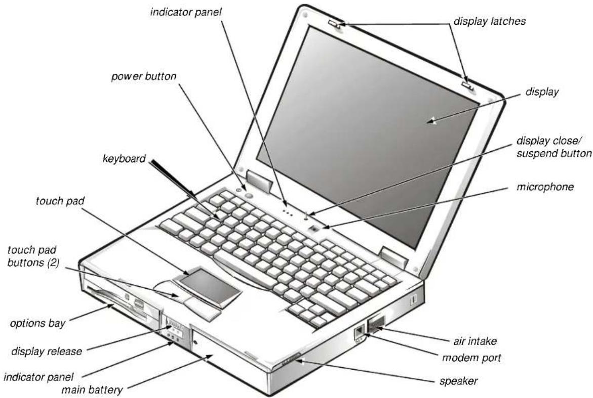
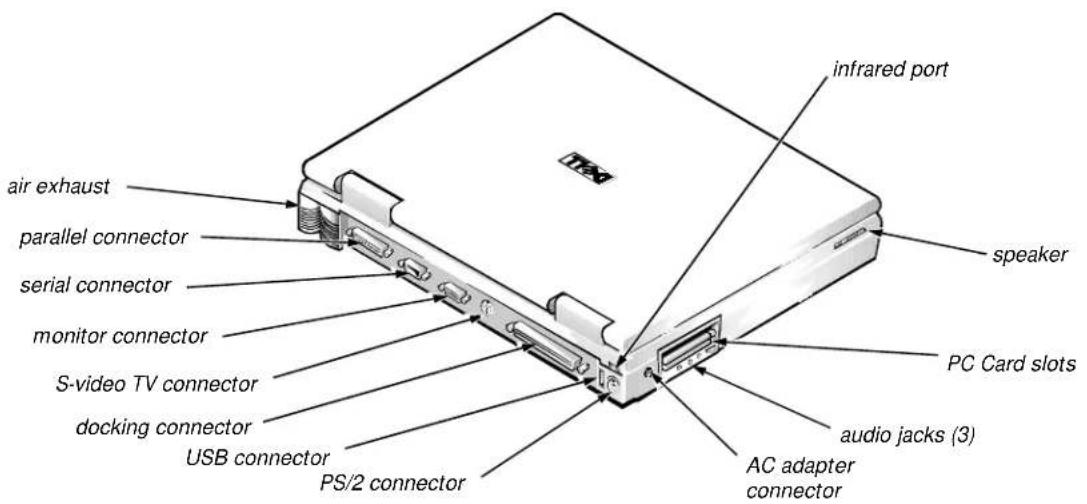
Figures 1-1 and 1-2 illustrate front and back views of the Inspiron 7000.
text_image
indicator panel power button keyboard touch pad touch pad buttons (2) options bay display release indicator panel main battery display latches display display close/ suspend button microphone air intake modem port speakerFigure 1-1. Front View
text_image
infrared port air exhaust parallel connector serial connector monitor connector S-video TV connector docking connector USB connector PS/2 connector acu adapter connector speaker PC Card slots audio jacks (3)Figure 1-2. Back View
Status Display
Three status lights are located in the indicator panel directly above the keyboard (see Figure 1-3):
- Num Lock: Solid green light when Num Lock is on. Press
to turn this feature on or off. - Caps Lock: Solid green light when Caps Lock is on. Press
to turn this feature on or off. - Scroll Lock: Solid green light when Scroll Lock is on. Press
to turn this feature on or off.
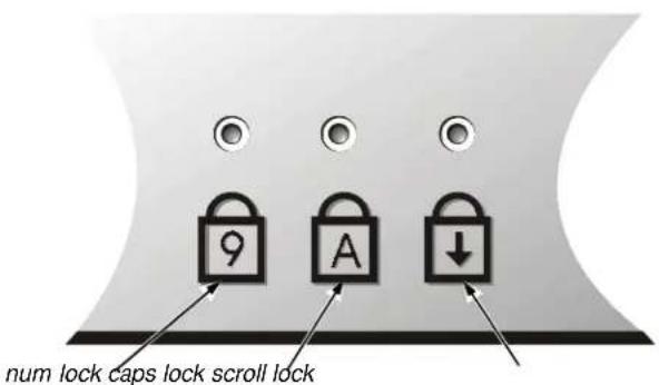
text_image
num lock caps lock scroll lockFigure 1-3. Indicator Panel above Keyboard
Five additional status lights are located on the front of the unit, three in the indicator panel below the display latch and two on the left side (see Figure 1-4):
- System power: Solid green light when the system is on; blinking green light when system is in suspend state.
- Hard-disk drive activity: Blinking green light as the drive is being accessed.
- Battery status:
— Solid green light when the battery is fully charged.
— Blinking green light when the battery is charging.
— No light when the battery is discharging.
— Solid amber light when the battery charge is low (7 percent life remaining).
— Blinking amber light when the battery charge is critically low (1.5 percent life remaining). The system beeps when this level is first reached.
- Floppy disk drive activity: Blinking green light as the drive is being accessed.
- CD-ROM or DVD-ROM drive activity: Blinking green light as the drive is being accessed.
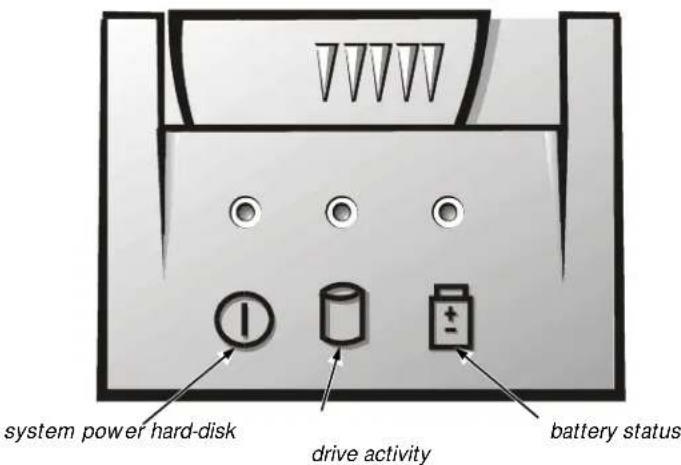
text_image
system power hard-disk drive activity battery statusFigure 1-4. Indicator Panel on Front of Computer
Battery Charge Gauge
The battery charge gauge (see Figure 1-5) on the rear of the main and secondary batteries has five charge-level indicator lights that indicate how much battery charge remains. Each light indicates approximately 25 percent battery charge. Press the status button to the right of the lights to check the total battery charge. If none of the lights are on, the battery has no charge left.
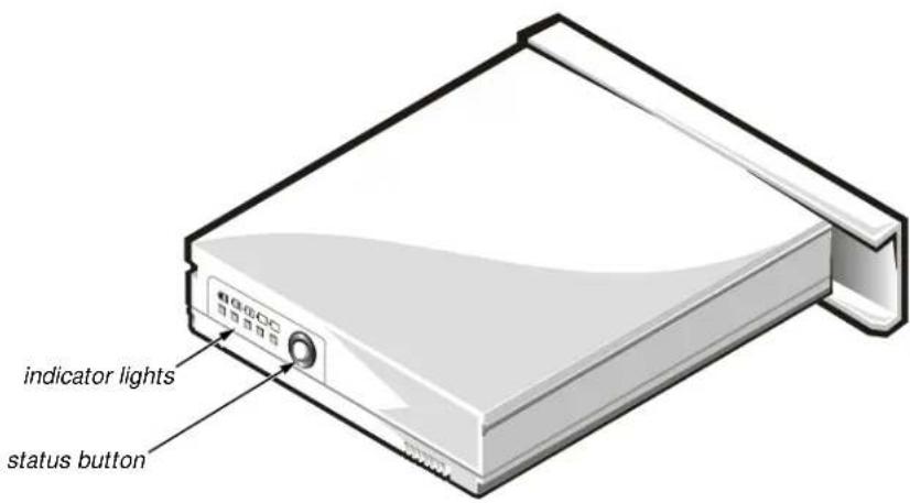
text_image
indicator lights status buttonFigure 1-5. Battery Charge Gauge

CAUTION: If only one or none of the charge-level indicator lights are lit, the battery is almost completely discharged. Do not use the battery unless the computer is connected to AC power or unless you install a second charged battery.
System Power
The power button controls power to the system. The computer receives power from either the AC adapter connected to an electrical outlet or from up to two batteries. The system has built-in power management features that remove power from parts of the computer that are not being used.
Attach the AC power adapter to the computer, whenever possible, to conserve battery power. When the AC adapter is attached, the battery is charged while the computer uses AC power.
The Power Menu of the Setup program has power conservation features. To open the Main Menu of the Setup program, press
Power Management Mode
The power management mode has four settings:
- Select Customized (the default) to control the power-saving time-outs individually.
- Select Disabled to turn off power management.
- Select Maximum Performance to conserve power but allow greatest system performance. When this setting is selected, the Standby Time-Out option is set automatically to 4 minutes, and the Suspend Time-Out option is disabled. The Smart CPU Mode option is set automatically to Off.
- Select Maximum Power Savings to conserve the greatest amount of system power. When this setting is selected, the StandbyTime-Out option is set automatically to 1 minute, and the Suspend Time-Out option is set automatically to 5 minutes. The Smart CPU Mode option is set automatically to On.
Smart CPU Mode
Smart CPU Mode allows the computer to slow down the microprocessor automatically if it is not being used. Settings for this option are:
- On — Allows the computer to slow down the microprocessor when it is inactive
- Off (the default) — Keeps the microprocessor running at its normal operating speed regardless of microprocessor inactivity
To increase battery operating time, set the Smart CPU Mode option to On.
Standby Time-Out
Standby Time-Out conserves battery power by turning off various devices in the system, including the display, but leaves the computer ready to resume operations immediately. Use Standby Time-Out when you leave the computer unattended for less than a few minutes.
Standby Time-Out lets you determine how long the computer remains idle (no I/O activity) before activating standby mode to conserve battery power. Settings for this option are Disabled, 1 min., 2 min., 4 min., 6 min., 8 min., 12 min., and 16 min.
To increase battery operating time, set this option to a lower number of minutes. Press any key on the built-in keyboard to resume normal computer operation.
Suspend Time-Out
Suspend Time-Out lets you determine how long the computer remains idle (no I/O activity) before activating suspend mode. Settings for this option are Disabled, 5 min., 10 min., 15 min., 20 min., 30 min., 40 min., and 60 min.
To increase battery operating time, set this option to a lower number of minutes.
Suspend Mode
The Save-to-disk option under Suspend Mode copies all system data to a reserved area on the hard-disk drive and then turns off all power to the computer. When you resume normal operation, the same programs will be running and the same files will be open that were loaded before you activated this mode. Use Save-to-disk suspend mode to conserve battery power or to preserve system data by quickly saving it to the hard-disk drive if you are about to run out of battery power.
Interrupt Assignments
Table 1-1 lists the interrupt assignments.
Table 1-1. Interrupt Assignments
| IRQ LineUsed/Available |
| IRQ0 Generated by the system timer |
| IRQ1 Generated by the keyboard controller to signal that the keyboard output buffer is full |
| IRQ2 Cascade to second interrupt controller |
| IRQ3 Reserved |
| IRQ4 Used by the communications port (COM1) |
| IRQ5 Used by the audio controller |
| IRQ6 Generated by the diskette drive controller to indicate that the diskette drive requires the attention of the microprocessor |
| IRQ7 Used by the parallel port |
| IRQ8 Generated by the system real-time clock |
| IRQ9 Free |
| IRQ10 Generated by the USB |
| IRQ11 Generated by the cardbus controller |
| IRQ12 Generated by the keyboard controller to indicate that the output buffer of the integrated touch pad or external PS/2 mouse is full |
| IRQ13 Used by the math coprocessor on the microprocessor |
| IRQ14 Generated by the hard-disk drive to indicate that the drive requires the attention of the microprocessor |
| IRQ15 Generated by the secondary IDE controller (CD-ROM drive or DVD-ROM drive) to indicate that the drive requires attention of the microprocessor |
Technical Specifications
Table 1-2 lists the technical specifications for the Inspiron 7000.
Table 1-2. Technical Specifications
| Microprocessor | ||
| Microprocessor type . . . . . . Intel Mobile Pentium II microprocessor with MMX technology | ||
| Microprocessor speed. . . . . . . Inspiron 7000 D266XT or D266GT: 266 MHz Inspiron 7000 D300GT: 300 MHz | ||
| Internal cache . . . . . . . . . . . . . . . . . . . . . . . . . . . . . . . . . . . . . . . . . . . . . . . . . . . . . . . . . . . . . . . . . . . . . . . . . . . . . . . . . . . . . . . . . . . . . . . . . . . . | ||
| External cache . . . . . . . . . . . . . . . . . . . . . . . . . . . . . . . . . . . . . . . . . . . . . . . . . . . . . . . . . . . . . . . . . . . . . . . . . . . . . . . . . . . . . . . . . . . . . . . . . . | 32 KB | |
| Math coprocessor . . . . . . . . . . . . . . . . . . . . . . . . . . . . . . . . . . . . . . . . . . . . . . . . . . . . . . . . . . . . . . . . . . . . . . . . . . . . . . . . . . . . . . . . . . . . . . . . . . . | ||
| Chip Set and Bus | ||
| System chip set . . . . . . . . . . . . . . . . . . . . . . . . . . . . . . . . . . . . . . . . . . . . . . . . . . . . . . . . . . . . . . . . . . . . . . . . . . . . . . . . . . . . . . . . . . . . . . . . . . . | Intel Mobile 440BX AGP | |
| Data bus width . . . . . . . . . . . . . . . . . . . . . . . . . . . . . . . . . . . . . . . . . . . . . . . . . . . . . . . . . . . . . . . . . . . . . . . . . . . . . . . . . . . . . . . . . . . . . . . . . . . 64 bits | ||
| DRAM bus width. . . . . . . . . . . . . . . . . . . . . . . . . . . . . . . . . . . . . . . . . . . . . . . . . . . . . . . . . . . . . . . . . . . . . . . . . . . . . . . . . . . . . . . . . . . . . . . . . . . . Address bus width. . . . . . . . . . . . . . . . . . . . . . . . . . . . . . . . . . . . . . . . . . . . . . . . . . . . . . . . . . . . . . . . . . . . . . . . . . . . . . . . . . . . . Flash EPROM. . . . . . . . . . . . . . . . . . . . . . . . . . . . . . . 4 Mbits | ||
| PC Card | ||
| PCI controller. . . . . . . . . . . . . . . . . . . . Texas Instruments PCI 1220 cardbus controller | ||
| PC Card connectors. . . . . . . . two type I, two type II, or one type III | ||
| Cards supported . . . . . . . . . . 3.3-V and 5-V | ||
| PC Card connector size . . . . 68 pins | ||
| Data width (maximum) . . . 32 bits | ||
| Memory | ||
| Architecture. SDRAM | ||
| Memory module capacities. 32- and 64-MB | ||
| Standard RAM 32-MB SODIMM (13.3-inch display) 64-MB SODIMM (14.1-inch display) | ||
| Maximum RAM 192 MB | ||
| Memory access time/ clock frequency 66 MHz | ||
| BIOS address. F000:0000 | ||
Table 1-2. Technical Specifications(continued)
| Connectors | |
| Serial (DTE) | one 9-pin connector; 16550-compatible, 16-byte buffer |
| Parallel | one 25-hole connector; normal (unidirectional), bidirectional, EPP 1.9, or ECP |
| Monitor | one 15-hole connector |
| PS/2 keyboard/mouse | one 6-pin mini-DIN connector |
| Infrared | one IrDA 1.1 port |
| Expansion connector | 240 pins |
| TV-out | one 7-pin S-video |
| Audio | microphone, headphones/speakers, and line-out jacks |
| USB | one 4-pin connector |
| Integrated Audio | |
| Audio type | Sound Blaster Pro-compatible voice and music functions, HRTF 3D positional audio, hardware wavetable |
| Audio controller | ESS Technology Maestro-2 |
| Conversion | 20 bit (stereo analog-to-digital and digital-to-analog) |
| Hardware wavetable synthesizer | 64-voice |
| Interfaces: | |
| Internal | PCI bus, microphone, dual stereo speakers |
| External | microphone (minijack), headphones, line-in |
| Internal speaker amplifier | 1.0 W stereo (0.5 W per speaker) |
| External microphone input voltage range | 280 mV peak-to-peak |
| Line/audio input voltage range | 2.8 V peak-to-peak |
| Controls | volume can be controlled through thumb wheel, software application menus, and keyboard |
| Video | |
| Video type | AGP 2X with sideband signals, hardware 3D accelerator, DVD motion compensation, ImpacTV-2 quality TV output |
| Video controller | ATI 3D Rage LT Pro AGP 2X |
| Video memory | 4 or 8 MB 100 MHz SGRAM |
| LCD interface | 65 MHz LVDS |
| TV support | NTSC or PAL in S-video and composite modes |
| 13.3-Inch Display | |
| Type | active-matrix color (TFT) |
| Dimensions (active area): | |
| Height | 214 mm (8.4 inches) |
| Width | 296.5 mm (11.7 inches) |
| Diagonal | 337.8 mm (13.3 inches) |
| Maximum resolution | 1024 x 768 pixels; 4 billion colors as supported by application software |
| Response time (typical) | 50 ms |
| Operating angle | 0° (closed) to 170° |
| Dot pitch | 0.264 mm |
| Power consumption | 3.9 W |
| Controls | brightness can be controlled through key combinations |
| 14.1-Inch Display | |
| Type | active-matrix color (TFT) |
| Dimensions (active area): | |
| Height | 228.5 mm (8.9 inches) |
| Width | 299.5 mm (11.8 inches) |
| Diagonal | 358.1 mm (14.1 inches) |
| Maximum resolution | 1024 x 768 pixels; 4 billion colors as supported by application software |
| Response time (typical) | 40 ms |
| Operating angle | 0° (closed) to 170° |
| Dot pitch | 0.279 mm |
| Power consumption | 4.6 W |
| Controls | brightness can be controlled through key combinations |
| Keyboard | |
| Number of keys | 87 (U.S. and Canada); 88 (Europe); 88 (Japan) |
| Key travel | 3.0 ± 0.5 mm (0.12 ± 0.02 inch) |
| Key spacing | 19.1 mm (0.75 inch) |
| Layout | QWERTY/AZERTY/Kanji |
| Touch Pad | |
| Interface | PS/2-compatible |
| X/Y position resolutions(graphics table mode) | 20 points/mm (500 points/inch) |
| Size: | |
| Thickness | 4.65 mm (0.18 inch) at highest component |
| Width | 64-mm (2.52-inch) sensor-active area |
| Height | 47.0-mm (1.85-inch) rectanglewith 0.5-mm (0.02-inch) tabs |
| Weight | 15 g (0.52 ounce) ± 0.5 g (0.001 ounce) |
| Power: | |
| Supply voltage | 5 V ± 10% |
| Supply current | 4 mA (maximum operating current) |
| Main and Secondary Battery | |
| Type | lithium ion |
| Maximum dimensions: | |
| Height | 23.8 mm (0.94 inch) |
| Depth | 148.2 mm (5.83 inches) |
| Width | 116.2 mm (4.58 inches) |
| Weight | 0.60 kg (1.32 lb) |
| Voltage | 14.4 VDC |
| Capacity | 65 WH |
| Main and Secondary Battery (continued) | |
| Charge time (approximate): ^1 | |
| Computer on . . . . . . . . 3.5 hours | |
| Computer off . . . . . . . . 3 hours | |
| Operating time (approximate) ^1 | 2.5 to 3.5 hours with one battery; 5 to 7 hours with two batteries |
| Life span (approximate) ^1 | 500 discharge/charge cycles |
| Ambient temperature range: | |
| Charge . . . . . . . . . . . . . . . . . . . . . . . . . . . . . . . . . . . . . . . . . . . . . . . . . . . . . . . . . . . . . . . . . . . . . . . . . . . . . . . . . . . . . . . . . . . . . . . . . . . . | 0° to 40°C (32° to 104°F) |
| Discharge . . . . . . . . . . . . . . . . . . . . . . . . . . . . . . . . . . . . . . . . . . . . . . . . . . . . . . . . . . . . . . . . . . . . . . . . . . . . . . . . . . . . . . . . . . . . . . . . . . . 0° to 60°C (32° to 140°F) | |
| Storage . . . . . . . . . . . . . . . . . . . . . . . . . . . . . . . . . . . . . . . . . . . . . . . . . . . . . . . . . . . . . . . . . . . . . . . . . . . . . . . . . . -20° to 50°C (-4° to 122°F) | |
| AC Adapter | |
| Input voltage . . . . . . . . . . . . . . . . . . . . . . . . . . . . . . . . . . . . . . . . . . . . . . . . . . . . . . . . . . . . . . . . . . . . . . . . . . . . . . . . . . . . . . . . . . . . . . . . . . .90 to 264 VAC | |
| Input current (maximum). . . . 1.5 A at 90 VAC, full load | |
| Input frequency . . . . . . . . . . . . . . . . . . . . . . . . . . . . . . . . . . . . . . . . . . . . . . . . . . . . . . . . . . . . . . . . . . . . . . . . . . . . . . . . . . . . . . . . . . . . . . . . . . .47 to 63 Hz | |
| Output current . . . . . . . . . . . . . . . . . . . . . . . . . . . . . . . . . . . . . . . . . . . . . . . . . . . . . . . . . . . . . . . . . . . . 3.5 A (continuous) | |
| Output power . . . . . . . . . . . . . . . . . . . . . . . . . . . . . . . . . . . . . . . . . . . . . . . . . . . . . . . . . . . . 70 W | |
| Rated output voltage . . . . . . . . . . . . . . . . . . . . . . . . . . . . . . . . . 20 VDC | |
| Dimensions: | |
| Height . . . . . . . . . . . . . . . . . . . . . . . . . . . . . . . . . . . . . . . . . . . . . . . . . . . . . . . . . . . . 29.6 mm (1.17 inches) | |
| Width. . . . . . . . . . . . . . . . . . . . . . . . . . . . . . . . . . . . . . 60.0 mm (2.36 inches) | |
| Depth. . . . . . . . . . . . . . . . . . . . . . . . . . . . . . . . . . 105 mm (4.13 inches) | |
| Weight (with cables) . . . . . . . 0.3 kg (0.66 lb) | |
| Temperature range: | |
| Operating. . . . . . . . . . . . . . . . . . . 5° to 35°C (41° to 95°F) | |
| Storage. . . . . . . . . . . . . . -20° to 50°C (-4° to 122°F) | |
| Physical (Computer) | |
| Height | 54 mm (2.1 inches) |
| Width | 318 mm (12.52 inches) |
| Depth | 254 mm (10 inches) |
| Weight (includes hard-disk drive, diskette drive, and CD-ROM drive) | 3.74 kg (8.25 lb) with 13.3-inch display3.8 kg (8.37 lb) with 14.1-inch display |
| Environmental (Computer) | |
| Temperature: | |
| Operating | 5° to 35°C (41° to 95°F) |
| Storage | -20° to 50°C (-4° to 122°F) |
| Relative humidity | 10% to 90% (noncondensing) |
| Maximum vibration: | |
| Operating | 0.8 GRMS using a random-vibration spectrum that simulates air shipment |
| Storage | 1.3 GRMS using a random-vibration spectrum that simulates truck shipment |
| Maximum shock: ^2 | |
| Operating | 1.52 m/sec (4.98 ft/sec)(less than or equal to a pulse width of 2 ms) |
| Storage | 2.03 m/sec (6.66 ft/sec)(less than or equal to a pulse width of 2 ms) |
| Altitude: | |
| Operating | 0 to 3048 m (0 to 10,000 ft) |
| Storage | 0 to 12,192 m (0 to 40,000 ft) |
2 Measured with the hard-disk drive in head-parked position.
natural_image
Illustration of stacked books with a computer and tablet (no text or symbols)CHAPTER 2
Initial Procedures
This chapter describes initial procedures that can help you diagnose a computer problem. These procedures can often reveal the source of a problem or indicate the correct starting point for troubleshooting the computer. Dell recommends that you perform these initial procedures in the order they are presented.
Initial User Contact
When you first contact a user who has a problem, ask the user to describe the problem and the conditions under which it occurs. A verbal description can often indicate the cause of a problem or indicate the appropriate troubleshooting procedure to use. After the user describes the problem, follow these steps:
- Ask the user to back up any data on the hard-disk drive if the computer's condition permits.
See the "Maintaining Your Computer" section of the online System User's Guide.
- Ask the user to try to duplicate the problem by repeating the operations he or she was performing at the time the problem occurred.
Can the user duplicate the problem?
Yes. Proceed to step 3.
No. Proceed to the next section, "Visual Inspection."
- Observe the user to determine whether he or she is making an error, such as typing an incorrect key combination or entering a command incorrectly.
Is the problem a result of user error?
Yes. Instruct the user in the proper procedure or direct him or her to the appropriate user documentation for a description of the correct procedure.
No. Proceed to the next section, "Visual Inspection."
Visual Inspection

CAUTION: Before you proceed with the visual inspection, ensure that the user has saved all open files and exited all open application programs if possible.
The visual inspection consists of a quick inspection of the exterior of the computer and any attached peripherals, including making any necessary corrections. For information about the proper removal and installation of computer components, as instructed in the following procedure, see Chapter 4, "Removing and Replacing Parts."
To perform a visual inspection, follow these steps:
- Determine the power state of the computer.
If the system is on, go to step 2.
If you are unsure whether the system is on, shut down and restart the system, and then go to step 2.
-
Turn off any attached peripherals, and then shut down the computer.
-
Verify that the exterior of the computer is free of any obvious physical damage.
-
If the computer is operating from an AC adapter, verify the following:
a. The AC adapter's AC power cable is connected to both the AC adapter and the electrical outlet. The AC adapter's indicator light should be on.
b. The AC adapter's DC power cable is properly connected to the computer's AC adapter connector.
c. The AC adapter and cables are free of any obvious physical damage.
-
If the computer is operating from battery power, remove any installed batteries, verify that they are free of any obvious physical damage, verify that the connectors on the battery and inside the battery bay are not damaged, and then reinsert the batteries into their respective compartments. Press the test button located on the back of each battery to make certain that there is a charge.
-
Remove the combo module (CD-ROM/diskette drive or DVD-ROM/diskette drive) if installed, verify that it is free of any obvious physical damage, verify that the connectors on the combo module and inside the options bay are not damaged, and then reinsert the drive into the options bay.
-
Remove any installed PC Cards from the PC Card slot, verify that they are free of any obvious physical damage, verify that the connectors on the PC Cards and inside the PC Card cage are not damaged, and then reinsert the card(s) into the PC Card slot.
-
If there is a memory area problem and the computer has memory modules, remove the memory modules from the main board, verify that they are free of any obvious physical damage, verify that the connectors on the modules and in the memory module sockets are not damaged, and then reinstall the modules.
- Raise the LCD display and verify that the computer is free of any obvious physical damage.
- Verify that the keyboard is free of any obvious physical damage and that its keys operate freely.
- Verify that the touch pad operates freely.
- If an external monitor is connected, verify the following:
a. The monitor's interface cable is properly attached to the external-monitor connector on the computer's I/O panel.
b. The monitor's power cable is attached to a power source and is free of any obvious physical damage.
c. The monitor, its interface cable, and connectors are free of any obvious physical damage.
d. The monitor is on.
e. The monitor's controls are set according to the instructions in the documentation for the monitor.
- If an external mouse is connected, verify the following:
a. The mouse is properly connected to the keyboard/keypad/mouse connector on the computer's I/O panel.
b. The mouse, its cable, and connectors are free of any obvious physical damage.
c. The mouse's ball and pushbuttons operate freely.
- For any attached serial or parallel devices, verify the following:
a. The device's interface cable connector is correctly attached to the appropriate port connector on the computer's I/O panel.
b. The captive screws that secure the connectors at each end of the interface cable are secure enough to ensure a firm connection.
c. The attached device, its interface cable, and connectors are free of any obvious physical damage.
- Turn on any attached peripherals and then the computer.
Does the problem recur?
Yes. Go to the next section, "Observing the Boot Routine."
No. No further steps are necessary.
Observing the Boot Routine
After you perform a visual inspection as described in the previous section, boot the computer from a diagnostics diskette and, while the boot routine is running, observe the computer for any indications of problems.

NOTE: To prevent possible damage to the original diagnostics diskette, always use a backup copy of the diagnostics diskette when servicing a user's computer. Dell recommends that users make copies of the Dell Diagnostics Diskette. For instructions, see “Before You Start Testing” in Chapter 4, “Running the Dell Diagnostics,” of the Dell Inspiron 7000 Reference and Troubleshooting Guide.
To observe the boot routine, follow these steps:
- Turn off the computer and any attached peripherals.
- Insert a diagnostics diskette into the diskette drive. Turn on all peripherals and then the computer.
- Watch the indicators at the front of the keyboard. Depending on how your computer is configured, after various indicators flash momentarily in the status display panel, some indicators should light up and remain on.
Do these indicators light up within seconds after the boot routine starts?
Yes. Go to step 4.
No. Troubleshoot the power subsystem.
-
While the boot routine is running, observe the computer for any of the following:
-
Diskette-drive and hard-disk drive access indicator activity
These indicators light in response to data being transferred to or from the drives. If either of these indicators fails to light during the boot routine, troubleshoot the diskette drive or hard-disk drive subsystem, as appropriate.
• System error messages
These messages can indicate problems or provide status information. If a system error message is displayed, refer to Table 3-2. - Beep codes
A beep code is a series of beeps that indicates an error condition. If the computer emits a beep code, refer to Table 3-1.

NOTE: The computer beeps once shortly after the system boots. This beep is normal and not part of a beep code.
- Any unusual sounds
- Observe the display for the Diagnostics Menu of the Dell Diagnostics.
Does the Diagnostics Menu appear on the display?
Yes. See "Running the Dell Diagnostics" in Chapter 3.
No. Go to step 6.
- Insert another copy of the diagnostics diskette into the diskette drive and reboot the computer.
Does the Diagnostics Menu appear on the display?
Yes. See "Running the Dell Diagnostics" in Chapter 3.
No. Go to the next section, “Eliminating Resource Conflicts.”
Eliminating Resource Conflicts
Devices within or connected to the computer may require dedicated memory spaces, interrupt levels, and/or DMA channels. Because different devices can be configured at different times, it is possible that the same resource is assigned to two or more devices.
Disconnect all peripherals and remove all PC Cards to make sure that the computer failure is not caused by faulty devices.
If you suspect that resource conflicts might exist, check the computer and reassign the resources as necessary. For more information about resolving conflicts, see Chapter 3, “Troubleshooting Your Computer,” in the Reference and Troubleshooting Guide.
Getting Help
If none of the procedures in this chapter reveal the source of the problem or lead to the proper troubleshooting steps for determining the source of the problem, contact Dell for technical assistance. For instructions, see Chapter 5, "Getting Help," in the Reference and Troubleshooting Guideor the "Contacting Dell" section of the online System User's Guide
natural_image
Illustration of stacked books with a computer and tablet (no text or symbols)CHAPTER 3
Beep Codes and Error Messages
This chapter describes beep codes and system error messages that can occur during system start-up or, in the case of some failures, during normal computer operation. The tables in this chapter list faults that can cause a beep code or system error message to occur and the probable causes of the fault in each case.
If a faulty computer does not emit beep codes or display system error messages to indicate a failure, you should load the diagnostics and run the appropriate tests to help isolate the source of the problem. See “Running the Dell Diagnostics” found later in this chapter.
POST Beep Codes
If the display cannot display error messages during POST, the computer may emit a series of beeps that identifies the problem or that can help you identify a faulty component or assembly. For example, one beep, a burst of three short beeps, and two more single beeps (beep code 1-3-1-1) means that the system has encountered a DRAM refresh error condition, probably caused by a faulty system board.
Table 3-1 lists the beep codes that may be generated during POST. Most beep codes indicate a fatal error that requires replacement of the main board or other corrective actions before the computer can operate.
Table 3-1. POST Beep Codes
| Beep CodeErrorProbable Causes | |
| 1-2 Memory module not being properly identified or used | Faulty memory module or faulty main board |
| 1-2-2-3 ROM BIOS checksum failure Faulty main board | |
| 1-3-1-1 DRAM refresh failure Faulty main board | |
| 1-3-1-3 Keyboard controller test failure | Faulty keyboard or faulty main board |
| 1-3-4-1 RAM failure on address line nnnn | Faulty memory module or faulty main board |
| 1-3-4-3 RAM failure on data bits nnnnof high byte on memory bus | Faulty memory module or faulty main board |
| 1-4-1-1 RAM failure on data bits nnnnof low byte on memory bus | Faulty memory module or faulty main board |
| 2-1-2-3 Check ROM copyright notice failure | Faulty main board |
| 2-2-3-1 Interrupt mask register failure Faulty main board | |
System Error Messages
Table 3-2 lists (in alphabetical order) system error messages that may appear on the display during the boot routine or during normal computer operation.
Table 3-2. System Error Messages
| Message | Definition | Probable Causes |
| CMOS battery is dead-Replace and run Setup | The CMOS battery does not have enough charge to power the computer. | CMOS battery completely discharged.Faulty CMOS battery or main board. |
| Diskette drive A error | Connector loose or diskette faulty. | Faulty or incorrectly inserted diskette in drive. Faulty diskette drive. Faulty main board. Faulty or loose external cable. |
| Extended RAM failed at offset: nnnn | Extended memory not configured properly or failed at memory address nnnn. | Faulty or improperly seated memory module. Faulty main board. |
| MessageDefinitionProbable Causes | ||
| Failing bits: nnnn | Memory failed at RAM address nnnn. | Faulty or improperly seated memory module. Faulty main board. |
| Fixed disk 0 failure | The hard-disk drive failed to initialize. | Corrupted hard-disk drive boot sector or configuration file. Faulty hard-disk drive. Faulty main board. |
| Fixed disk controller failure | The hard-disk drive controller may be faulty. | Faulty hard-disk drive. Faulty main board. |
| Incorrect drive A type-run Setup | The diskette drive is not identified properly in the Setup program. | Incorrect drive configuration. Faulty connections. Faulty diskette drive. Faulty main board. |
| Keyboard controller error | The keyboard controller is faulty. | Faulty keyboard connection. Faulty keyboard. Faulty main board. |
| Keyboard errorIf an external keyboard is being used, a cable or connector may be loose or the keyboard may be faulty. If the built-in keyboard is being used, it may be faulty. A key on the built-in keyboard may have been pressed while the computer was booting. | Built-in keyboard: faulty keyboard or key pressed while computer booting. External keyboard: cable or connector loose. Faulty keyboard or key pressed while computer booting. | |
| Operating system not found | The operating system may be corrupted. Or, the operating system cannot be found on the hard-disk drive or on the diskette in the diskette drive. | Incorrect drive configuration. Operating system not installed on hard-disk drive or diskette drive not bootable. Faulty connections. Faulty drive. Faulty main board. |
| Parity check 1 nnnn | A parity error was found in the system bus at address nnnn. | Faulty main board. |
| Parity check 2 nnnn | A parity error was found in the I/O bus at address nnnn. | Faulty main board. |
| Real time clock error | The CMOS battery that supports data stored in NVRAM may be dead. | Faulty battery. Faulty main board. |
| Shadow RAM failed at offset: nnnn | Shadow RAM failed at address nnnn. | Faulty or improperly seated memory module. Faulty main board. |
| System battery is dead-Replace and run Setup | CMOS battery dead. Faulty CMOS battery or main board. | |
| System cache error-cache disabled | The primary cache internal to the micro-processor has failed. | Faulty microprocessor. |
| System CMOS checksum bad-run Setup | The BIOS has been updated.CMOS has been corrupted or modified, possibly by an application program that changes data stored in CMOS. | BIOS has been updated.Verify correct CMOS settings, save, and exit. |
| System RAM failed at offset: nnnn | System RAM failed at address nnnn in the 64-KB block at which the error was detected. | Faulty or improperly seated memory module. Faulty main board. |
| System timer error | A chip on the system board may be malfunctioning. | Faulty main board. |
Running the Dell Diagnostics
CAUTION: To prevent damage to the original diagnostics diskette, always use a backup copy of the diagnostics diskette when servicing a user's computer. Dell recommends that users make several copies of this diskette to ensure that one is always available.
The Dell Diagnostics contains tests that aid in troubleshooting the computer. The diagnostics diskette contains the following test groups:
• RAM — Tests the main memory
• System Set — Tests the primary functions of the main board
• Video — Tests the video subsystem
- Keyboard — Tests the keyboard subsystem
- Mouse — Tests the mouse/touch pad subsystem
- Diskette Drives — Tests the diskette drive subsystem

- Hard-Disk Drives (Non-SCSI) — Tests the IDE hard-disk drive subsystem
- IDE CD ROM Drives — Tests a CD-ROM drive subsystem
- Serial/Infrared Ports — Tests the serial communications port
- Parallel Ports — Tests the parallel communications port
• Audio — Tests the operation of the audio chip set
Before starting the Dell Diagnostics, you must configure the computer correctly. For more information, see “Before You Start Testing” in Chapter 4, “Running the Dell Diagnostics,” of the Reference and Troubleshooting Guide
Follow these steps to start the diagnostics:
- Install a CD-ROM drive in the options bay.
- Turn off the computer.
- Place a copy of the Dell Diagnostics Diskette in the diskette drive, and boot the computer.
Starting the diagnostics causes the Dell logo screen to appear, followed by a message indicating that the diagnostics is loading. Before the diagnostics loads, a program tests the portion of main memory (RAM) required for loading the diagnostics. If a main memory error is detected, a message appears on the screen telling you a memory module has failed.
If no errors are found in main memory, the diagnostics loads, and the Diagnostics Menu appears. This menu lets you choose the following options or exit to the MS-DOS ^® prompt:
- Run All Tests — Runs all tests for a thorough test of the computer
- Run Quick Tests — Runs preselected tests to quickly locate a computer failure or to indicate where further testing is needed to isolate a failure
- Run Specific Tests—Tests a particular area or subsystem of the computer
natural_image
Illustration of stacked books with a computer and tablet (no text or symbols)CHAPTER 4
Removing and Replacing Parts
This chapter provides procedures for removing and replacing components and assemblies. Unless otherwise noted, each of the procedures in this chapter assumes the following:
- The computer and any attached peripherals are turned off and the peripherals are disconnected from the computer's I/O panel.
- A part can be replaced or installed by performing the removal procedure in reverse order.
When performing the procedures in this chapter that require the computer to be open, use a book or something similar to support the display assembly. The angle of the display assembly with respect to the base assembly should not exceed 170 degrees.
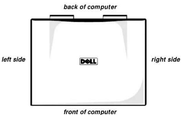
Locations or directions relative to the computer are shown in Figure 4-1 unless otherwise specified.
text_image
back of computer left side D&LL right side front of computerFigure 4-1. Computer Orientation
Recommended Tools
Most of the procedures require the use of one or more of the following tools:
• Small flat-blade screw driver
• Number 1 Phillips-head screw driver
• Antistatic grounding strap
- Dental pick
- Small scribe or nylon flat blade
• Nut driver (5 mm and 5.5 mm)
Screw Identification and Tightening

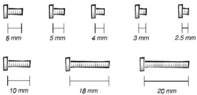
CAUTION: It is essential that the correct length screw be used when reinstalling a screw. Otherwise, hardware damage could result. Make sure that the screw is properly aligned with its corresponding hole, and avoid overtightening.
Where applicable, information about screw lengths is provided in illustrations. Before installing a screw, match the screw to the screw length graphics in Figure 4-2 to check for correct length.
text_image
6 mm 5 mm 4 mm 3 mm 2.5 mm 10 mm 18 mm 20 mmFigure 4-2. Screw Identification
Precautionary Measures
Before performing any of the procedures in this chapter, read the following warning.

WARNING FOR YOUR PERSONAL SAFETY AND PROTECTION OF THE EQUIPMENT
Before you start to work on the computer, perform the following steps in the sequence indicated.
- Turn off the computer and any attached peripherals.
- Disconnect the computer and any attached peripherals from electrical outlets to reduce the potential for personal injury or shock.
- Ground yourself by attaching an antistatic grounding strap to your wrist and to an unpainted metal surface on the computer's I/O panel. If an antistatic grounding strap is not available, periodically discharge static electricity from your body by touching one of the connectors on the I/O panel.
Precautionary measures include disconnecting the computer from the AC adapter and port replicator and removing the main battery, PC Cards, hard-disk drive, memory module cover, video card cover, memory modules, and devices in the options bay.
To take these precautionary measures, follow these steps:
- Determine the power state of the computer.
If the system is on, go to step 2.
If you are unsure whether the system is on, shut down and restart the system, and then go to step 2.
-
Turn off any attached peripherals, and then shut down the computer.
-
Disconnect the computer and any attached peripherals from electrical outlets to reduce the potential for personal injury or shock.
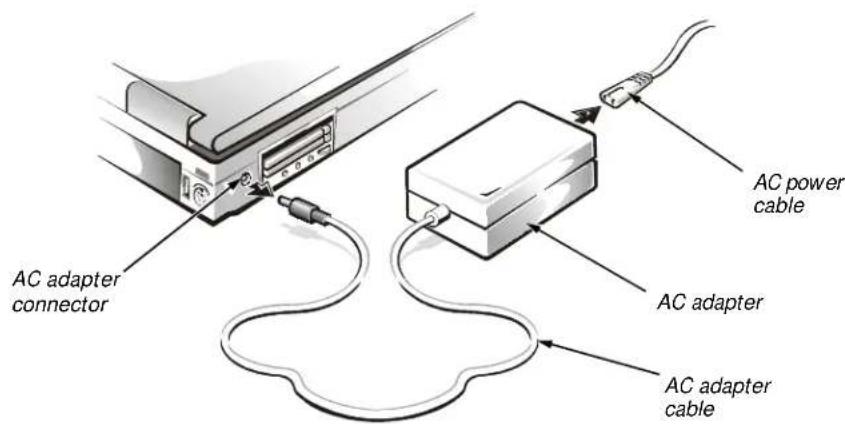
If the computer has an AC adapter, disconnect the AC power cable from the electrical outlet and then from the AC adapter; then disconnect the AC adapter from the computer (see Figure 4-3) or from the Inspiron Port Replicator II.
text_image
AC adapter connector AC power cable AC adapter AC adapter cableFigure 4-3. AC Adapter Removal
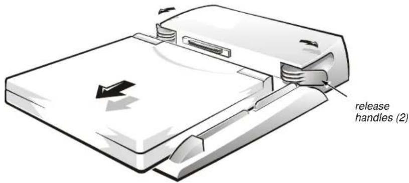
- If the computer is connected to a port replicator, pull both release handles on the sides of the replicator to undock the computer (see Figure 4-4).
text_image
release handles (2)Figure 4-4. Computer Removal From Inspiron Port Replicator II
- Remove the main battery from the battery compartment.
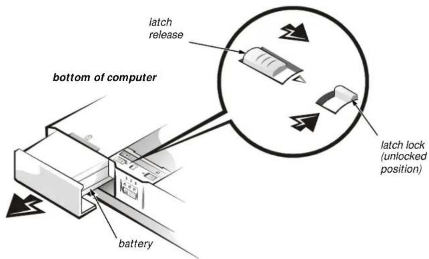
Unlock the latch lock on the bottom of the computer by flipping it toward the back of the computer (see Figure 4-5). Slide the latch release in the direction of the arrow. Keep holding the latch release with one hand while pulling the battery out of the compartment with the other.
text_image
bottom of computer latch release latch lock (unlocked position) batteryFigure 4-5. Main Battery Removal
The plastic front bezel on the battery slides back and forth, which allows it to be used in the options bay as a secondary battery, and can be removed.
On the back of the battery is a battery charge gauge. The five charge-level lights indicate the total battery charge, ranging from fully charged to completely discharged. Press the status button to the right of the lights to check the level of the total battery charge. See “Battery Charge Gauge” in Chapter 1 for more information.
- Remove any PC Cards.
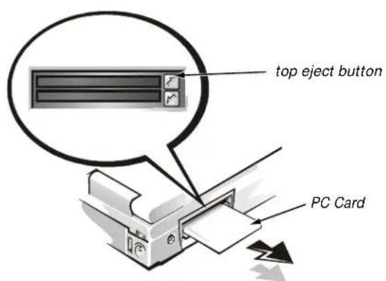
To remove a type I or type II PC Card from the top connector (see Figure 4-6), press the top eject button twice. To remove a type 1 or type II PC Card from the bottom connector, press the bottom eject button twice. To remove a type III card, press the bottom eject button twice.

NOTE: The first time you press an eject button, the eject button itself pops out. The second time you press the eject button, the PC Card is released and extends slightly from the slot.
Grasp the end of the card, and pull it completely from the slot.
text_image
top eject button PC CardFigure 4-6. PC Card Removal
- Remove the hard-disk drive assembly.

CAUTION: When the hard-disk drive is not in the computer, store it in a hard-disk drive case to protect it from exposure to static electricity.

CAUTION: Handle the hard-disk drive gently and don't bump or drop the drive. Rough handling could induce failure or loss of data.
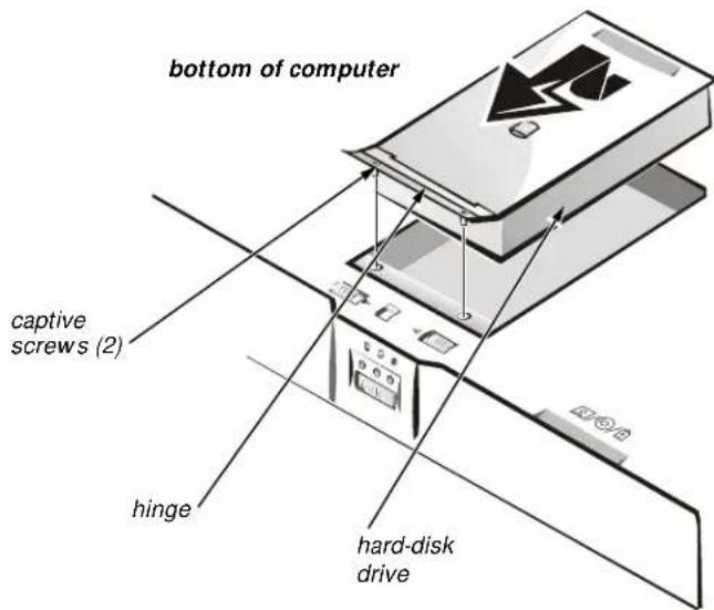
Loosen the two captive screws that secure the hard-disk drive into the bottom of the computer. The front edge of the cover pops up slightly. Slide the hard-disk drive toward the front of the computer and then lift the drive out of the computer (see Figure 4-7).
text_image
bottom of computer captive screws (2) hinge hard-disk driveFigure 4-7. Hard-Disk Drive Removal
- Remove the video card and memory module covers.
Slide the video card cover as far as it will go in the direction of the arrow, and then remove the cover (see Figure 4-8). Remove the memory module cover in the same way.

text_image
video card cover bottom of computer memory module coverFigure 4-8. Memory Module and Video Card Cover Removal
To replace a cover, place it over the opening, leaving a small gap along the rounded edge, and then slide the cover toward the outside of the computer until it snaps into place.
9. Remove the memory modules.
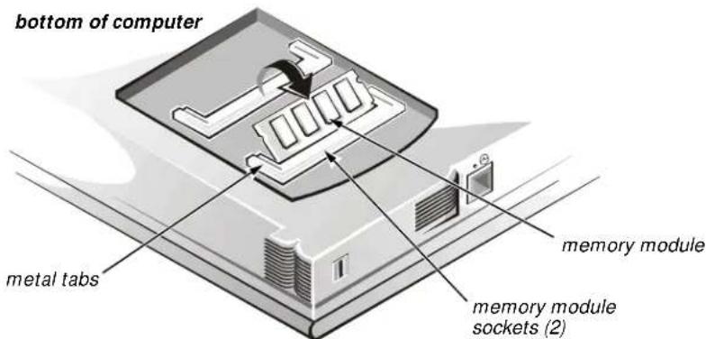
Carefully spread the inner metal tabs of the memory module socket to disengage the module from the socket. The module should pop up slightly. Then pull the memory module out of the socket (see Figure 4-9).
text_image
bottom of computer metal tabs memory module memory module sockets (2)Figure 4-9. Memory Module Removal
10. Remove the video card.
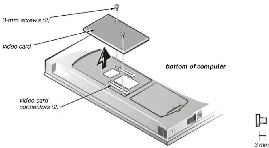
Remove the two 3-mm screws securing the video card (see Figure 4-10). Gently pull the video card off of the connectors on the bottom of the system board by lifting it at the notches located between the screws. Do not rock the card to remove it because this may damage the connectors.
text_image
3-mm screws (2) video card bottom of computer video card connectors (2) 3 mmFigure 4-10. Video Card Removal
Inspect the two thermal pads on the bottom of the system board and replace them if necessary.
- If present, remove the combo module or secondary battery from the options bay.
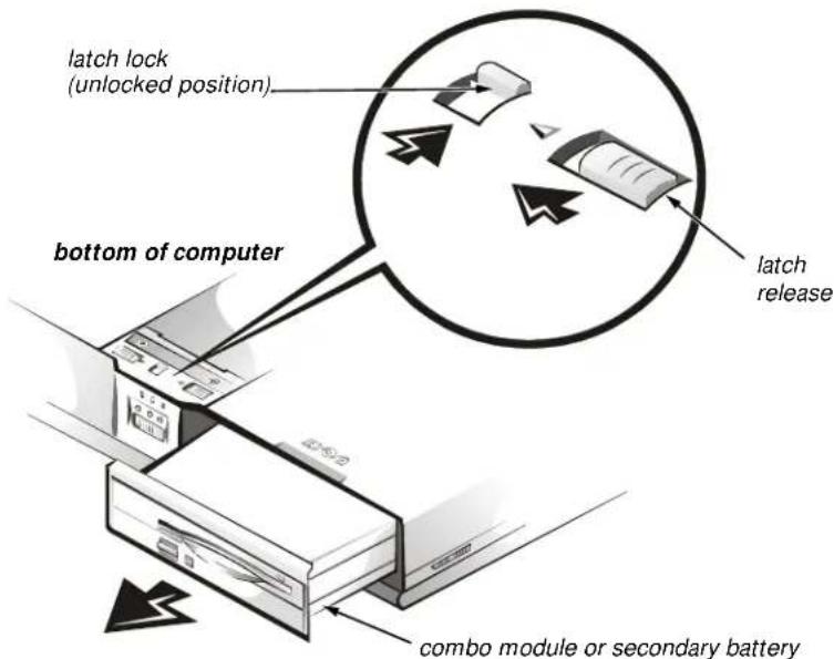
Unlock the latch lock by flipping it toward the back of the computer (see Figure 4-11). Slide the latch release in the direction of the arrow. Keep holding the latch release with one hand while pulling the combo module or secondary battery straight out of the options bay with the other.
text_image
latch lock (unlocked position) bottom of computer latch release combo module or secondary batteryFigure 4-11. Combo Module or Secondary Battery Removal

NOTE: If the computer is booted with a diskette drive or secondary battery in the options bay, you must reboot after installing the combo module in the options bay.

ZIF Connectors
CAUTION: ZIF connectors are fragile. To avoid breaking the connectors, touch them carefully. Do not apply too much pressure to the movable part of the connector when opening or closing it.
Some of the computer's interface connectors are zero insertion force (ZIF) connectors. These connectors are not removable; they must be released to disconnect a cable from them.
To disconnect a cable from a ZIF connector, follow these steps:
- Insert a small flat-blade screwdriver or dental pick under the movable part of the connector (see Figure 4-12).
For most ZIFs, carefully pry up first one end of the movable part of the connector and then the other end. Some ZIFs may need to be lifted in the center.
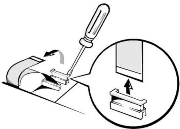
natural_image
Diagram showing a screwdriver using a tool to adjust a component, with an inset close-up of the component being inserted (no text or symbols present)Figure 4-12. Releasing a ZIF Connector
- Pull up gently on the movable part of the connector until the cable is released.
- Grasp the cable and pull it out of the connector.
To reconnect an interface cable to a ZIF connector, follow these steps:
- Use the flat-blade screwdriver or dental pick to open the movable part of the ZIF connector.
- Orient the end of the cable with the ZIF connector, and insert the end of the cable into the connector.
- While holding the cable in place, close the ZIF connector.
To ensure a firm connection, make sure that the ZIF connector is completely closed.
Exploded View of Components and Assemblies
Exploded views of the computer, the 13.3-inch and 14.1-inch display assemblies, the palmrest assembly, and the base assembly are shown in Figures 4-13, 4-14, 4-15, 4-16, and 4-17, respectively.
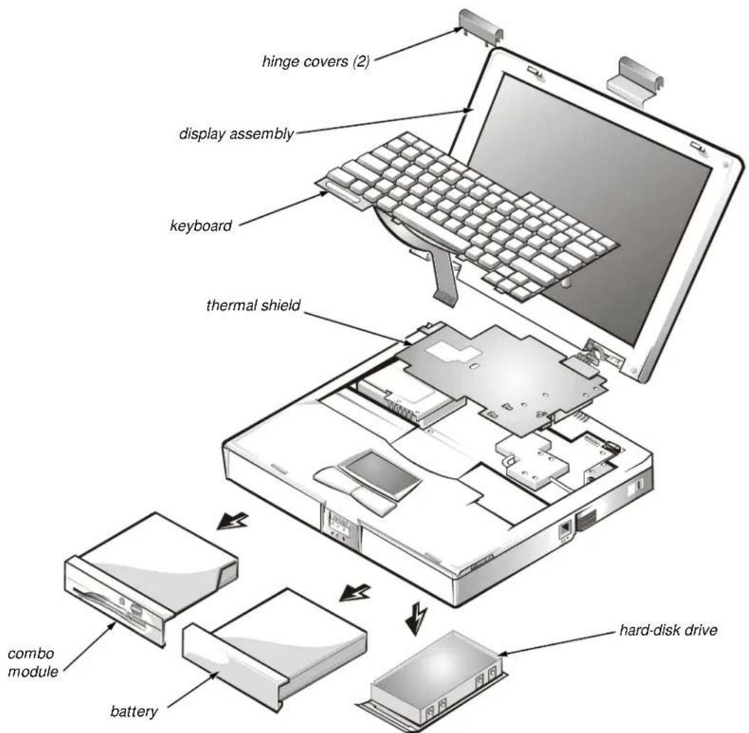
text_image
hinge covers (2) display assembly keyboard thermal shield combo module battery hard-disk driveFigure 4-13. Exploded View—Computer
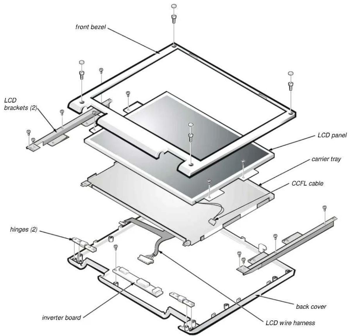
text_image
front bezel LCD brackets (2) LCD panel carrier tray CCFL cable hinges (2) inverter board back cover LCD wire harnessFigure 4-14. Exploded View—13.3-Inch Display Assembly
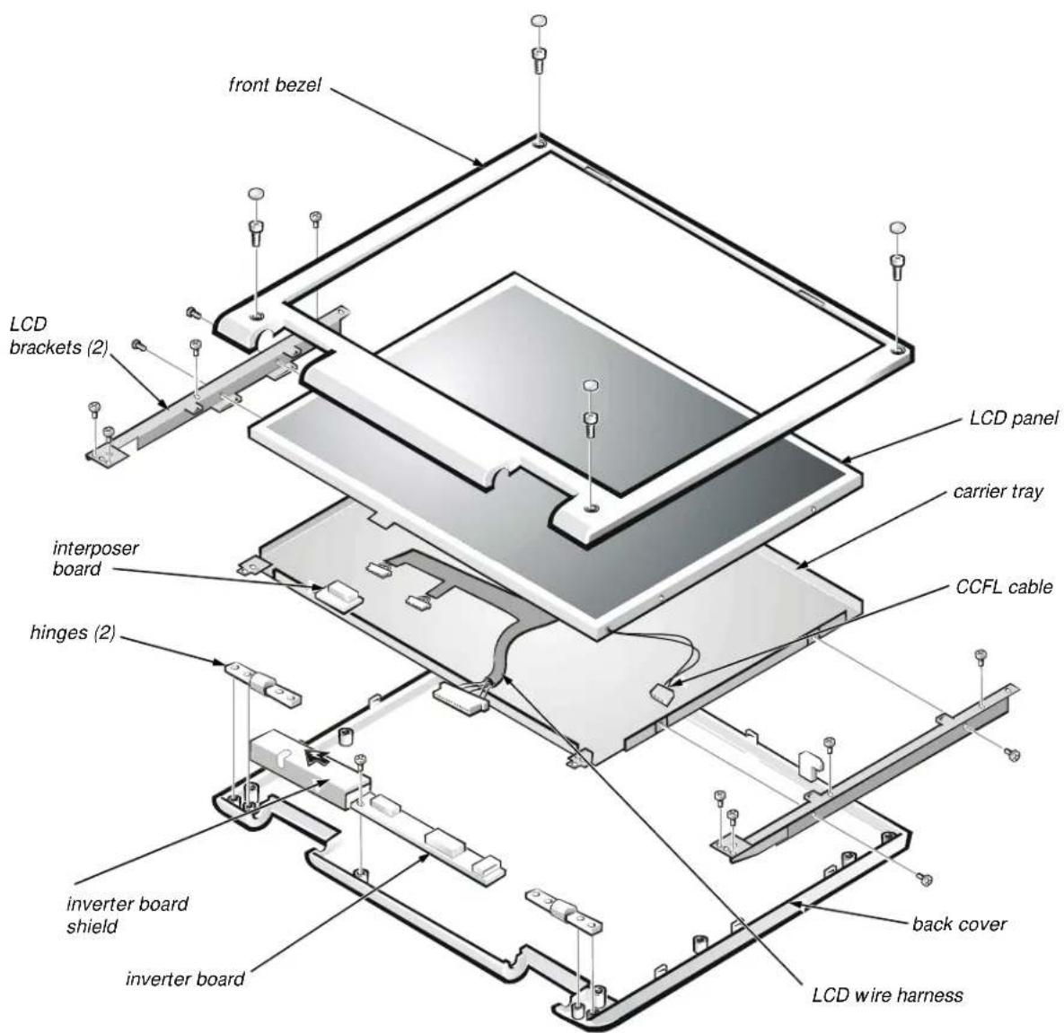
text_image
front bezel LCD brackets (2) LCD panel carrier tray CCFL cable interposer board hinges (2) inverter board shield inverter board back cover LCD wire harnessFigure 4-15. Exploded View—14.1-Inch Display Assembly
text_image
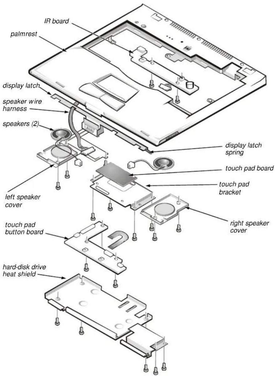
IR board palmrest display latch speaker wire harness speakers (2) left speaker cover touch pad button board hard-disk drive heat shield display latch spring touch pad board touch pad bracket right speaker coverFigure 4-16. Exploded View—Palmrest Assembly
text_image
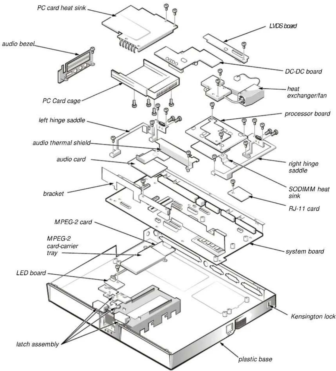
PC card heat sink LVDS board audio bezel DC-DC board heat exchanger/fan PC Card cage processor board left hinge saddle right hinge saddle audio thermal shield SODIMM heat sink audio card RJ-11 card bracket MPEG-2 card system board MPEG-2 card-carrier tray LED board Kensington lock latch assembly plastic baseFigure 4-17. Exploded View—Base Assembly
Factory Repair Parts and Assemblies
This section contains a parts list and procedures for removing and replacing factory components and subassemblies. This information is provided for reference only. Dell does not recommend removal and replacement of these parts in the field.
Table 4-1 lists the factory repair parts and assemblies available for the computer. Some parts may only be available as part of a kit or assembly. The subsections in this chapter provide instructions for removing and replacing these parts and assemblies. Customer kits are those parts or assemblies that are replaceable by a customer.
Table 4-1. Factory Repair Parts and Assemblies
| Part or Assembly NameOrder Name | |
| System Board | |
| System Board Assembly ASSY,SYS,PLN,NBK,I7000 | |
| System Board SYS,PLN,NBK,I7000 | |
| Plastic Frame SPCR,PLSTC,MTHBD,NBK,I7000 | |
| System/Keyboard BIOS IC,BIOS,SYS,NBK,I7000 | |
| I/O Bracket BRKT,MET,I/O,NBK,I7000 | |
| PC Card Cage Assembly ASSY,CAGE,MET,PCM CIA,I7000 | |
| PC Card Cage Top Half | |
| PC Card Cage Bottom Half | |
| Saddle Hinge, Bracket Right PLT,BRACE,HNG,LCD,RT,NBK,I7000 | |
| Saddle Hinge, Bracket Left PLT,BRACE,HNG,LCD,LF,NBK,I7000 | |
| Standoffs, Processor Board | STDF,6-32X1/4,HEX,CS,PRM,I7000 |
| Standoff, DC/DC Board | STDF,4-40X.3,HEX,CS,DCDC,I7000 |
| Standoff, Port Connector | STDF,M2.5X4.14,5.5HEX,BRS |
| Standoff, I/O Connector | STDF,4-40X6,4.8HEX,BRS |
| PC Card Heat Sink | HTSNK,PCM CIA,NBK,I7000 |
| Audio Thermal Shield | PLT,MET,PCM CIA,NBK,I7000 |
| Audio Card | CRD,INTFC,AUD,NBK,I7000 |
| DC/DC Board | CRD,INTFC,DC/DC,NBK,I7000 |
| Audio Bezel | CVR,PLSTC,AUD JK,NBK,I7000 |
| Processor Board (PRM/MMO) | |
| 266MHz Processor Board | PRM,5PP266,266M,512K,AGP |
| 300MHz Processor Board (PRM) | PRM,5PP300,300M,512K,AGP |
| Part or Assembly Name | Order Name |
| Heat Sink Assembly | |
| Heat Exchanger Assembly ASSY,CAGE,MET,THRM SOLN,I7000 | |
| Heat Exchanger, Metal Plate PLT,MET,CPU,NBK,I7000 | |
| SODIMM Heat Sink HTSNK,DIMM,PRM,NBK,I7000 | |
| PM Thermal Solution, Metal Blocks w/ Fan CAGE,MET,THRM SOLN,CPU,I7000 | |
| Fan FAN,25MMX25MM,5V,03W,I7000 | |
| Spacer SPCR,PLSTC,FAN,NBK,I7000 | |
| Thermal Kit ASSY,PAD,THRM,INTFC,NBK,I7000 | |
| Thermal Pad (Northbridge) PAD,THRM,INTFC,BX-CHIP,I7000 | |
| Thermal Pad (over processor) PAD,THRM,INTFC,CPU,I7000 | |
| Bottom Case | |
| Bottom Plastic | CVR,BTM,PLSTC,NBK,I7000 |
| Latch Assembly | ASSY,LTCH,LKG,BTM,PLSTC,I7000 |
| Latch Cover (Outer) | n/a |
| Latch Separator/Lock | n/a |
| Right Latch | n/a |
| Spring | n/a |
| Left Latch | n/a |
| Spring | n/a |
| Cover Latch Spring | n/a |
| Rubber Feet, Front | FOOT,RBR,BTM,NBK,I7000 |
| LED Board | CRD,INTFC,LED,NBK,I7000 |
| LED Board Cable | CBL,INTFC,LED,NBK,I7000 |
| RJ-11 Cover | CVR,SIDE,PLSTC,MDM,I7000 |
| Memory Door | DOOR,PLSTC,BTM,RAM,NBK,I7000 |
| VGA Door | DOOR,PLSTC,BTM,VGA,NBK,I7000 |
| Part or Assembly Name | Order Name |
| Upper Logic | |
| Palmrest Plastics CVR,BTM,PLSTC,NBK,I7000 | |
| Left Touch Pad Button n/a | |
| Right Touch Pad Button n/a | |
| Left Touch Pad Button Hinge n/a | |
| Right Touch Pad Button Hinge n/a | |
| Right Speaker Cover CVR,PLSTC,SPKR,RT,NBK,I7000 | |
| Left Speaker Cover CVR,PLSTC,SPKR,LF,NBK,I7000 | |
| Right Speaker w/ wire SPKR,0.6W,23M,RT,NBK,I7000 | |
| Left Speaker w/ wire | SPKR,0.6W,23M,LF,NBK,I7000 |
| Hard-Disk Drive Heat Sink, under Palmrest | HTSNK,HD,NBK,I7000 |
| Touch Pad Button Board | CRD,INTFC,BTN,TPAD,NBK,I7000 |
| Touch Pad Bracket | BRKT,MET,TPAD,NBK,I7000 |
| Touch Pad | CRD,INTFC,TPAD,NBK,I7000 |
| Touch Pad Flex Cable | CBL,FLEX,CRD,TPAD,NBK,I7000 |
| Touch Pad Button, Audio Cable | CBL,INTFC,TPAD,NBK,I7K |
| Display Latch Assembly | ASSY,LTCH,PLMRST,NBK,I7000 |
| Latch Button | n/a |
| Slide Mechanism | n/a |
| Spring | SPR,LTCH,NBK,I7000 |
| IR, Microphone Board | CRD,IR,NBK,I7000 |
| IR Cable | CBL,FLEX,CRD,IR,NBK |
| IR Lens 13.3" and 14.1" | LENS,IR,NBK,I7K |
| LCD Parts for 13.3-Inch | |
| 13.3" LCD Panel | LCD,TFT,XGA,13.3,I7000,LG |
| Front Bezel | BZL,PLSTC,LCD,13.3,NBK,I7000 |
| Display Hinge | HNG,MET,LCD,I7000 |
| Display Back Cover CVR,BK,LCD,13.3,I7000 | |
| Display Upper Rubber Bumper | BMPR,RBR,UPR,LCD,I7000 |
| Display Lower Rubber Bumper | BMPR,RBR,LWR,LCD,I7000 |
| LCD Flex Cable Assembly | CBL,FLEX,LCD,13.3,I7000,LG |
| LCD Shielding, behind panel | SHLD,EMI,LCD,13.3,NBK,I7000 |
| LCD Parts for 13.3-Inch (continued) | |
| Inverter Board CRD,INTFC,INVRTR,LG,13.1,I7000 | |
| Right Bracket BRKT,MET,RT,LCD,13.3,I7000 | |
| Left Bracket BRKT,MET,LF,LCD,13.3,I7000 | |
| LVDS Board CRD,INTFC,LVD,13.3,NBK,LG | |
| Right Hinge Cover CVR,HNG,PLSTC,RT,I7000 | |
| Left Hinge Cover CVR,HNG,PLSTC,LF,I7000 | |
LCD Parts for 14.1-Inch
| 14.1" LCD Panel LCD,TFT,XGA,14.1,I7000,LG | |
| Front Bezel BZL,PLSTC,LCD,14.1,I7000,LG | |
| LCD Flex Cable Assembly CBL,FLEX,LCD,14.1,I7000,LG | |
| Right Display Hinge HNG,MET,LCD,I7000 | |
| Display Back Cover | CVR,BK,LCD,13.3,I7000 |
| Display Upper Rubber Bumper | BMPR,RBR,UPR,LCD,I7000 |
| Display Lower Rubber Bumper | BMPR,RBR,LWR,LCD,I7000 |
| EMI Plate, Behind Panel | SHLD,EMI,LCD,14.1,I7K,LG |
| Inverter Board CRD,INTFC,INVRTR,LG,14.1,I7000 | |
| Right Bracket BRKT,MET,RT,LCD,14.1,I7K,LG | |
| Left Bracket BRKT,MET,LF,LCD,14.1,I7K,LG | |
| Right Hinge Cover CVR,HNG,PLSTC,RT,I7000 | |
| Left Hinge Cover CVR,HNG,PLSTC,LF,I7000 | |
| LVDS Board CRD,INTFC,LVD,14.1,NBK,LG | |
Keyboards
| Keyboard, US KYBD,87,US,NBK,I7000 | |
| Keyboard, UK | KYBD,88,UK,NBK,I7000 |
| Keyboard, Japan | KYBD,88,JPN,NBK,I7000 |
| Keyboard, German | KYBD,88,GER,NBK,I7000 |
| Keyboard, French | KYBD,88,FR,NBK,I7000 |
| Keyboard, Norwegian | KYBD,88,NOR,NBK,I7000,EMEA |
| Keyboard, Denmark | KYBD,88,DEN,NBK,I7000,EMEA |
| Keyboard, Swedish | KYBD,88,SWE,NBK,I7000,EMEA |
| Keyboard, Italian | KYBD,88,ITL,NBK,I7000,EMEA |
| Part or Assembly Name | Order Name |
| Screws | |
| Screw, 2.5 x 4 SCR,2.5X4,KSH,MS,CPS | |
| Screw, 2.5 x 6 SCR,2.5X6,BSH,MS,CPS | |
| Screw, 2.5 x 18 SCR,2.5X18,KSH,MS,CPS | |
| Screw, 2.5 x 20 SCR,2.5X20,PNH,MS,CPS | |
| Screw, 2.5 x 10 SCR,2.5X10,BSH,MS,CPS | |
| Screw, 2 x 4 SCR,2X4,FLH,MS,CPS | |
| Screw, 2 x 5 SCR,2X5,BSH,MS,CPS | |
| Screw, 2 x 3 SCR,2X3,KSH,MS,CPS | |
| Screw, 2 x 18 SCR,2X18,PNH,MS,CPS | |
| Screw, 3 x .5 SCR,3X.5,KSH,MS,CPS | |
| Screw, 2.5 x .45 SCR,2.5X.45,KSH,MS,CPS | |
| Screw, CD-ROM bezel SCR,1.7x.35,KSH,MS,CPS | |
| Hard-Disk Drive Holder | |
| Hard-Disk Drive Cover Assembly ASSY,CARRIER,MTG,HD,NBK,I7000 | |
| Plastic Cover | CVR,PLSTC,HD,I7000 |
| Top Shield | PLT,MET,BTM,HD,I7000 |
| Connector Board | CON,2X22,INTFC,IDE,HDD,I7000 |
| Internal Options—Modem, PCI, VGA | |
| Modem Kit | |
| 56K Modem MDM,56K,INT,RJ11,I7000 | |
| Modem Carrier Box | CVR,MET,MDM,I7000 |
| RJ-11 Card | CRD,MDM,RJ11,INTFC,NBK,I7000 |
| Modem Flex Cable | CBL,FLEX,MDM,RJ11,NBK,I7000 |
| Twisted Pair Cable | CBL,INTFC,MDM,MTHBD,NBK,I7000 |
| Miscellaneous Parts | |
| Modem Kit | KIT,CBL,ADPT,MDM,INT,I7000,US |
| Phone Cable | CBL,PHONE,MDM,PCMCIA,MHZ |
| Adaptor Coupler | ADPT,COUPLER,MDM,PCMCIA,RJ-11 |
| Assembly, Internal MPEG-2 Card | ASSY,CRD,DCDR,MPEGII,INT,I7000 |
| MPEG-2 Card | CRD,DCDR,MPEG-II,INT,I7000 |
| Metal Cover | CVR,MET,MPEG-II,I7000 |
| Video Card 4MB CRD,VID,VGA,4M,ATI,I7000 | |
| Video Card 8MB CRD,VID,VGA,8M,ATI,I7000 | |
| LCD Rubber Bumper Kit KIT,BMPR,RBR,LCD,I7000 | |
| Upper | BMPR,RBR,UPR,LCD,I7000 |
| Lower | BMPR,RBR,LWR,LCD,I7000 |
| Foot | FOOT,RBR,CVR,BTM,13.3,I7000 |
| Customer Replaceable Units (CRU)(All CRUs are sent as customer kits) | |
| Customer Kit, Memory Module Cover CUS,DOOR,PLSTC,BTM,RAM,I7000 | |
| Plastic Door DOOR,PLSTC,BTM,RAM,NBK,I7000 | |
| Customer Kit, Video Card Cover CUS,DOOR,PLSTC,BTM,VGA,I7000 | |
| Plastic Door DOOR,PLSTC,BTM,VGA,NBK,I7000 | |
| Customer Kit, Rubber Bumpers, 13.3" CUS,FOOT,PAD,BMPR,13.3,I7000 | |
| Foot | FOOT,RBR,CVR,BTM,13.3,I7000 |
| Upper | BMPR,RBR,UPR,LCD,I7000 |
| Lower | BMPR,RBR,LWR,LCD,I7000 |
| Customer Kit, Rubber Bumpers, 14.1" CUS,FOOT,PAD,BMPR,14.1,I7000 | |
| Foot | FOOT,RBR,CVR,BTM,14.1,I7000 |
| Lower | BMPR,RBR,LWR,LCD,I7000 |
| Upper | BMPR,RBR,UPR,LCD,I7000 |
| Customer Kit, 4.0GB Hard-Disk Drive, IBM CUS,HD,4GB,I,IBM,I7K | |
| 4.0GB Subassembly | |
| Boot Information INFO,1ST BOOT,HARD DRIVE | |
| Screw, 3 x .5 SCR,3X.5,KSH,MS,CPS | |
| Hard-Disk Drive Carrier Assembly ASSY,CARRIER,MTG,HD,NBK,I7000 | |
| Top Shield | PLT,MET,BTM,HD,I7000 |
| Plastic Cover | CVR,PLSTC,HD,I7000 |
| Connector Board | CON,2X22,INTFC,IDE,HDD,I7000 |
| Customer Kit, 4.0GB Hard-Disk Drive, Fujitsu | CUS,HD,4GB,I,12.5MM,FJTSU,I7K |
| 4.0GB Subassembly | |
| Boot Information INFO,1ST BOOT,HARD DRIVE | |
| Screw, 3 x .5 SCR,M3.0x0.5x4,PHH,NPL | |
| Customer Replaceable Units (CRU) (continued) | |
| Hard-Disk Drive, 4.0GB HD,4.0GB,I,F2,12.5MM,FJTSU | |
| Hard-Disk Drive Carrier Assembly ASSY,CARRIER,MTG,HD,NBK,I7000 | |
| Top Shield PLT,MET,BTM,HD,I7000 | |
| Plastic Cover CVR,PLSTC,HD,I7000 | |
| Connector Board CON,2X22,INTFC,IDE,HDD,I7000 | |
| Customer Kit, 6.4GB Hard-Disk Drive, Fujitsu CUS,HD,6.4G,I,12.5MM,FJTSU,I7K | |
| 6.4GB Subassembly | |
| Boot Information INFO,1ST BOOT,HARD DRIVE | |
| Screw, 3 x 0.5 SCR,M3.0x0.5x4,PHH,NPL | |
| Hard-Disk Drive, 6.4GB HD,6.4GB,I,F2,12.5MM,FJTSU H10 | |
| Hard-Disk Drive Carrier Assembly ASSY,CARRIER,MTG,HD,NBK,I7000 | |
| Top Shield PLT,MET,BTM,HD,I7000 | |
| Plastic Cover CVR,PLSTC,HD,I7000 | |
| Connector Board CON,2X22,INTFC,IDE,HDD,I7000 | |
| Customer Kit, 6. 4GB Hard-Disk Drive, IBM CUS,HD,6.4GB,I,12.5MM,IBM,I7K | |
| 6.4GB Subassembly | |
| Boot Information INFO,1ST BOOT,HARD DRIVE | |
| Screw, 3 x 0.5 SCR,M3.0x0.5x4,PHH,NPL | |
| Hard-Disk Drive, 6.4GB HD,6.4GB,I,F2,12.5MM,IBM ACDIA | |
| Hard-Disk Drive Carrier Assembly ASSY,CARRIER,MTG,HD,NBK,I7000 | |
| Top Shield PLT,MET,BTM,HD,I7000 | |
| Plastic Cover CVR,PLSTC,HD,I7000 | |
| Connector Board CON,2X22,INTFC,IDE,HDD,I7000 | |
| Customer Kit, 8.1GB Hard-Disk Drive, IBM CUS,HD,8.1GB,I,F2,17MM,IBM,NBK | |
| 8.1GB Subassembly | |
| Boot Information | INFO,1ST BOOT,HARD DRIVE |
| Screw, 3 x 0.5 SCR,M3.0x0.5x4,PHH,NPL | |
| Hard-Disk Drive, 8.0GB HD,8.1GB,I,F2,17MM,IBM,NBK | |
| Hard-Disk Drive Carrier Assembly ASSY,CARRIER,MTG,HD,NBK,I7000 | |
| Top Shield PLT,MET,BTM,HD,I7000 | |
| Plastic Cover CVR,PLSTC,HD,I7000 | |
| Connector Board CON,2X22,INTFC,IDE,HDD,I7000 | |
| Customer Kit, MPEG-2 Card CUS,CRD,VID,MPEGII,PCMCIA,INSP | |
| MPEG-2 Card CRD,VID,DECODER,PCMCIA,MPEGII | |
| Kit,MPEG-2 Card KIT,CBL\CDSK,VID,MPEGII,PCMCIA | |
| Customer Kit, CD-ROM/FDD CUS,CD/FD,680M,24X/1.44M,I7000 | |
| CD-ROM/FDD Assembly ASSY,CD/FD,24X/1.44M,I7000 | |
| Combo Plastics Kit ASSY,BRKT,PLSTC,DVD/CD,I7K | |
| CD-ROM | CD,680M,24X,I,INT,INSP |
| Front Plastic Bezel BZL,FRT,PLSTC,CD,SANYO,I7000 | |
| Customer Kit, DVD-ROM/FDD CUS,DVD/FD,17G/1.44M,I7000 | |
| DVD-ROM/FDD Assembly ASSY,DVD/FD,17G/1.44M,I7000 | |
| Combo Plastics Kit ASSY,BRKT,PLSTC,DVD/CD,I7K | |
| CD-ROM | CD,680M,24X,I,INT,INSP |
| Front Plastic Bezel BZL,FRT,PLSTC,CD,SANYO,I7000 | |
| Combo Plastics Kit | |
| Plastic Cover | CVR,PLSTC,FD,NBK,I7000 |
| CD-ROM/DVD-ROM Metal Bracket | BRKT,CD/DVD,MET,I7000 |
| EMI Shield | SHLD,EMI,FD,F3,COMBO,NBK,I7000 |
| Back Metal Plate | PLT,BK,MET,COMBO,I7000 |
| Flex Cable | CBL,FLEX,FD,CITIZEN,NBK,I7000 |
| Customer Kit, TV Out Cable | CUS,CBL,COAX,TV OUT,I7K |
| Coax Cable Kit | CBL,COAX,TV OUT,I7K |
| Customer Kit, 32MB Memory | CUS,DIMM,32M,66M,2K,144,I7000 |
| DIMM, 32MB | DIMM,32,66M,4X64,4K,144 |
| Customer Kit, 64MB Memory | CUS,DIMM,64M,66M,2K,144,I7000 |
| DIMM, 64MB | DIMM,64,66M,8X64,4K,144 |
| Customer Kit, Main Battery | CUS,BTRY,MAIN,60W,LIIION,I7000 |
| Battery Assembly | ASSY,BTRY,60W,LIIION,NBK,I7000 |
| 60W Lithium Ion Battery | BTRY,MAIN,60W,LIIION,NBK,I7000 |
| Bezel | BZL,FRT,PLSTC,BTRY,NBK,I7000 |
| Assembly, Secondary Battery ASSY,BTRY,#2,60W,LIION,I7000 | |
| 60W Lithium Ion Battery BTRY,60W,12,LIION,NBK,I70 | |
| Bezel BZL,FRT,PLSTC,BTRY,NBK,I7 | |
| US Power Cord CORD,PWR,110V,6F,AC ADPT,US | |
| Customer Kit, Flash BIOS CUS,DSK,FLASH,BIOS,UPG,I7000 | |
| Kit, BIOS Flash KIT,DSK,FLASH,BIOS,UPG,I7000 | |
| Diskette Envelope | ENV,DSK,F3,PLSTC |
| Card Lag | CARD,LAG |
| BIOS Diskette | DSK,BIOS,FLASH,F3,I7000 |
| Customer Kit, AC Adapter | CUS,ADPT,AC,EXT,19V,70W,I7000 |
| AC Adapter Only | ADPT,AC,EXT,19V,70W,NBK,I7000 |
| US Power Cord | CORD,PWR,110V,6F,AC ADPT,US |
| Customer Kit, Adaptor, US, APCC | CUS,ADPT,AC,EXT,19V,US,APCC |
| Customer Kit, Adaptor, UK, APCC | CUS,ADPT,AC,EXT,19V,UK,APCC |
| Customer Kit, Adaptor, AUS, APCC | CUS,ADPT,AC,EXT,19V,AUS,APCC |
| Customer Kit, Adaptor, EUR, APCC | CUS,ADPT,AC,EXT,19V,EUR,APCC |
| Customer Kit, Adaptor, 70W, EUR | CUS,ADPT,AC,EXT,19V,70W,EUR |
| Customer Kit, Adaptor, 70W | CUS,ADPT,AC,EXT,19V,70W,I7000 |
| Customer Kit, Adaptor, 70W, UK | CUS,ADPT,AC,EXT,19V,70W,UK |
| Customer Kit, Plastic Hinge Cover | CUS,CRV,PLSTC,HNG,I7000 |
| Left Plastic Hinge Cover | CVR,HNG,PLSTC,LF,I7000 |
| Right Plastic Hinge Cover | CVR,HNG,PLSTC,RT,I7000 |
| Dell Inspiron Port Replicator (Sierra) | |
| Customer Kit, Port Replicator | CUS,PPR,I/O,NBK,I7000,US |
| Port Replicator Assembly | ASSY,PPR,I/O,NBK,I7000 |
| AC Adaptor | ADPT,AC,EXT,19V,70W,NBK,I7000 |
| US Power Cord | CORD,PWR,110V,6F,AC ADPT,US |
| Sierra Kit (AMF Only) | KIT,PPR,I/O,NBK,I7000 |
| AC Adaptor | ADPT,AC,EXT,19V,70W,NBK,I7000 |
| US Power Cord | CORD,PWR,110V,6F,AC ADPT,US |
| Port Replicator Assembly ASSY,PPR,I/O,NBK,I7000 | |
| Dell Inspiron Port Replicator (Sierra) (continued) | |
| Left Release Lever LEVER,REL,LF,I/O PPR,NBK | |
| Right Release Lever LEVER,REL,RT,I/O PPR,NBK | |
| Lower Tray TRAY,LWR,PPR,I/O,NBK,I7K | |
| Upper Tray TRAY,UPR,PPR,I/O,NBK,I7K | |
| CRD,PLN | CRD,PLN,I/O,PPR,NBK,I7K |
| Customer Kit, Port Replicator, AUS, APCC CUS,PPR,I/O,I7000,NBK,AUS,APCC | |
| Customer Kit, Port Replicator, EUR CUS,PPR,I/O,I7000,NBK,EUR | |
| Customer Kit, Port Replicator, EUR, APCC CUS,PPR,I/O,I7000,NBK,EUR,APCC | |
| Customer Kit, Port Replicator, NBK, UK CUS,PPR,I/O,I7000,NBK,UK | |
| Customer Kit, Port Replicator, UK, APCC CUS,PPR,I/O,I7000,NBK,UK,APCC | |
| Customer Kit, Port Replicator, US, APCC CUS,PPR,I/O,I7000,NBK,US,APCC | |
| Customer Kit, Port Replicator, JPN,APCC CUS,PPR,I/O,NBK,I7000,JPN,APCC | |
| Diagnostics | |
| Diagnostics Kit, US | KIT,DSK,DIAG,DELL,3.94,F3,I7K |
| Diskette Envelope | ENV,DSK,F3,PLSTC |
| License Agreement Card | CARD,LAG |
| Diagnostics Diskette | DSK,DIAG,DELL,3.94,F3,WW,I7K |
| Customer Kit, System Software Diskette | CUS,SSD,F3,NBK,I7000 |
| System Software Diskette Kit | KIT,DSK,SSD,NBK,I7000 |
| Diskette Envelope | ENV,DSK,F3,PLSTC |
| Card Lag | CARD,LAG |
| Service Manual | |
| Service Manual | MNL,SERV,I7000,ENG |
| Removal and Replacement Guide | DOC,SERV,GDE,I7000,ENG |
| Reference/Troubleshooting Guide | GDE,REF/TRBLSHT,I7000,ENG |
| Setup Guide | GDE,SETUP,I7000,ENG |
| Drivers | |
| DVD-ROM Driver SRV,IMG,SW,DVD,NBK,I7000 | |
| Utilities Driver SRV,SW,UTIL,NBK,I7000 | |
| DVD-ROM Driver SRV,SW,DVD,NBK,I7000 | |
| Audio Driver, W98 SRV,SW,AUD,W98,NBK,I7000 | |
| Hypertext Driver SRV,SW,HYPTXT,I7000,WW | |
| Modem Driver SRV,SW,MDM,INT,NBK,I7000 | |
| MPEG-2 Driver SRV,SW,MPEGII,INT,NBK,I7000 | |
| Touch Pad Driver, W98 SRV,SW,TPAD,W98,NBK,I7000 | |
| Video Driver, W98 SRV,SW,VID,W98,NBK,I7000 | |
| Modems and LAN Cards | |
| Network Board 10/100 KIT,CRD,ADPT,NTWK,10/100,TX,3C | |
| Network Board 10BT | KIT,ADPT,NTWK,10BT,NBK,3COM |
| 56K WW Winmodem | MDM,56K,PCMCIA,FF,PSION,WW |
| 56K Value Modem | MDM,56K,PCMCIA,CBL/XJACK,USROB |
| Carrying Case | |
| Customer Kit, Carrying Case, Nylon | CUS,CASE,CRYG,NYL,UNIV,INSP,US |
| Carrying Case, Nylon, Universal | CASE,CRYG,NYL,NBK,UNIVERSAL |
| Customer Kit, Carrying Case, Leather | CUS,CASE,CRYG,LTHR,UNIV,INSP |
| Carrying Case, Leather, Universal | CASE,CRYG,LTHR,NBK,UNIVERSAL |
| Labels | |
| Regulatory Label | LBL,REG,NBK,GNRC,I7000 |
| Label, Intel Inside | LBL,INTEL INSIDE,PII,MMX,NBK |
| Regulatory Label, Modem, CAN | LBL,REG,MDM,INT,NBK,I7000,CAN |
| Regulatory Label, Battery | LBL,REG,BTRY,NBK,I7000 |
| Identification Label, Main Battery | LBL,IDENT,BTRY,NBK,I7000 |
| Identification Label, PPR | LBL,IDENT,PPR,NBK,I7K |
| Label, Win98/NT | LBL,NBK,POLY,COMBO WIN98/NT |
| Identification Label, I/O, PPR | LBL,IDENT,I/O,PPR,I7K |
| Labels (continued) | |
| Identification Label, Video Card LBL, IDENT, CRD, VID, VGA, I7000 | |
| Regulatory Label, Modem LBL, REG, MDM, INT, NBK, I7000 | |
| Regulatory Label, Replicator LBL, REG, RPLCTR, I7K | |
| Field Svc Bases (AMF only) | |
| 266MHz Field Service Base, no battery, 13.3" BASE, NBK, I7K, D266XT, NO BTRY | |
| Assembly w/o battery, 266MHz ASSY, NBK, BASE, I7000, 13.3, NOBATT | |
| 266MHz Field Service Base, no battery, 14.1" BASE, NBK, I7K, D266GT, NO BTRY | |
| Assembly w/o battery, 300MHz ASSY, NBK, BASE, I7000, 14.1, NOBATT | |
| 300MHz Field Service Base, no battery, 14.1" BASE, NBK, I7K, D300GT, NO BTRY | |
| Assembly w/o battery, 300MHz ASSY, NBK, BASE, I7000, 14.1, NOBATT | |
| Manufacturing Bases | |
| D266XT (13.3") Base, AGP, AMF BASE, I7000, D266XT, 13.3, AGP, AMF | |
| 13.3" Base Assembly | ASSY, NBK, BASE, I7000, 13.3, OEM |
| D266GT (14.1") Base, AGP, AMF | BASE, I7000, D266GT, 14.1, AGP, AMF |
| 14.1" Base Assembly | ASSY, NBK, BASE, I7000, 14.1, OEM |
| D300GT (14.1") Base, AGP, AMF | BASE, I7000, D300GT, 14.1, AGP, AMF |
| 14.1" Base Assembly | ASSY, NBK, BASE, I7000, 14.1, OEM |
| D266GT (14.1") Base, DAO, FR | BASE, I7000, D266GT, 14.1, DAO, FR |
| 14.1" Base Assembly | ASSY, NBK, BASE, I7000, 14.1, OEM |
| D266XT (13.3") Base, DAO, FR | BASE, I7000, D266XT, 13.3, DAO, FR |
| 13.3" Base Assembly | ASSY, NBK, BASE, I7000, 13.3, OEM |
| D300GT (14.1") Base, DAO, FR | BASE, I7000, D300GT, 14.1, DAO, FR |
| 14.1" Base Assembly | ASSY, NBK, BASE, I7000, 14.1, OEM |
| Assemblies | |
| Base Assembly, 13.3” ASSY,NBK,BASE,I7000,13.3,OEM | |
| Base Assembly, 14.1” ASSY,NBK,BASE,I7000,14.1,OEM | |
| Floppy Disk-Drive Assembly ASSY,FD,1.44M,11MM,COMBO,I7000 | |
| DVD-ROM Assembly ASSY,DVD,17G,2X,INT,MKE,I7000 | |
| Display Assembly, 13.3” ASSY,LCD,XGA,13.3,I7000,LG | |
| Display Assembly, 14.1” ASSY,LCD,XGA,14.1,I7000,LG | |
| System Board Assembly ASSY,SYS,PLN,I7000 | |
| Bottom Plastic Assembly ASSY,CVR,BTM,PLSTC,I7000 | |
| Palmrest Assembly | ASSY,PLMRST,PLSTC,BLK,I7000 |
| Touchpad Assembly | ASSY,TPAD,NBK,I7000 |
| Speaker Assembly | ASSY,SPKR,INT,NBK,I7000 |
| Palmrest Latch Assembly | ASSY,LTCH,PLMRST,NBK,I7000 |
| Bottom Plastic Assembly w/ Reg Label | ASSY,BTM CASE,W/LBL,I7K |
Hard-Disk Drive
The hard-disk drive resides in a carrier that mounts in the hard-disk drive compartment in the bottom of the computer (see Figure 4-18). Four screws secure the drive inside the carrier.
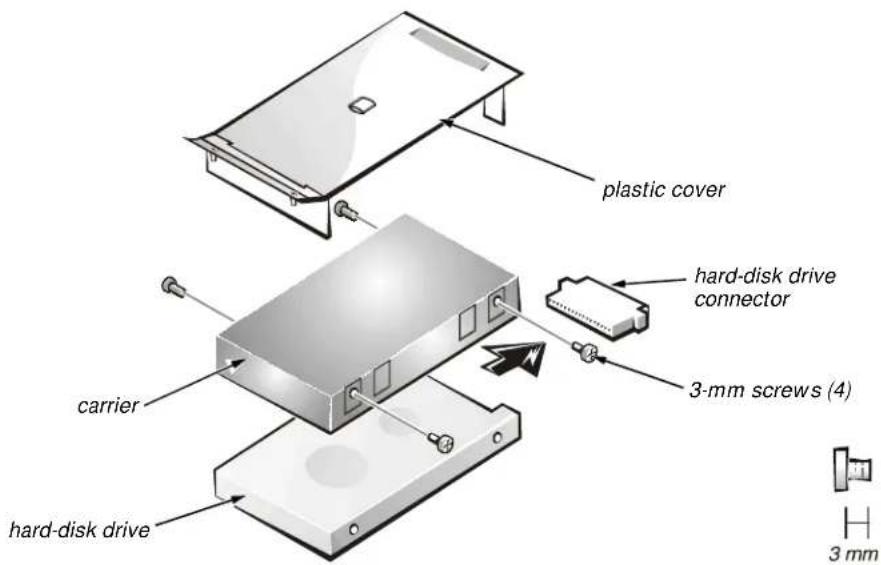
text_image
plastic cover hard-disk drive connector 3-mm screws (4) carrier hard-disk drive 3 mmFigure 4-18. Hard-Disk Drive Disassembly
To remove the hard-disk drive from the carrier, follow these steps:
- Remove the hard-disk drive assembly.
See “Precautionary Measures” found earlier in this chapter.
-
Remove the four 3-mm screws securing the hard-disk drive inside the carrier.
-
Remove the hard-disk drive from the carrier.
Turn the carrier over with one hand and let the drive fall out of the carrier into your other hand.
- Remove the metal carrier from the plastic cover.
The metal carrier is held in the plastic cover by two tabs on each end. Carefully pry the carrier away from the tabs.
- Pull the hard-disk drive connector off of the hard-disk drive.
Combo Module
The combo module contains either a CD-ROM drive or a DVD-ROM drive on top of a floppy diskette drive. The combo module (see Figure 4-19) resides in a carrier that slides into the options bay on the left side of the computer.
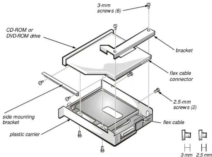
text_image
3-mm screws (6) CD-ROM or DVD-ROM drive bracket flex cable connector 2.5-mm screws (2) flex cable side mounting bracket plastic carrier 3 mm 2.5 mmFigure 4-19. CD-ROM/DVD-ROM Disassembly
To remove the CD-ROM drive or DVD-ROM drive from the plastic carrier, follow these steps:
- Remove the combo module.
See Figure 4-11 found earlier in this chapter. - Remove the two 3-mm screws from the L-shaped bracket.
- Remove the bracket.
- Remove the two 3-mm screws from the side of the plastic carrier.
- Remove the two 3-mm screws from the bottom of the plastic carrier.
- Disconnect the flex cable from the CD-ROM/DVD-ROM drive connector.
- Remove the CD-ROM/DVD-ROM drive from the plastic carrier.
Turn the carrier over with one hand and let the drive fall out of the carrier into your other hand.
To remove the side mounting bracket from the CD-ROM/DVD-ROM drive, follow these steps (see Figure 4-19):
- Remove the two 2.5-mm screws from the side of the CD-ROM/DVD-ROM drive.
- Remove the side mounting bracket.
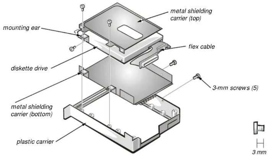
text_image
metal shielding carrier (top) mounting ear flex cable diskette drive metal shielding carrier (bottom) plastic carrier 3-mm screws (5) 3 mmFigure 4-20. Diskette Drive Disassembly
To remove the diskette drive from the plastic carrier (see Figure 4-20), follow these steps:
- Remove the two 3-mm screws from the top of the metal shielding carrier.
- Remove the two 3-mm screws from the side of the plastic carrier.

CAUTION: The metal on the shielding carrier is sharp. Be careful not to cut yourself.
- Lift the metal shielding carrier out of the plastic carrier.
Lift the back of the metal shielding carrier first and then slide it out. - Unsnap the metal latches along the top of the metal shielding carrier from the metal tabs on the bottom of the metal shielding carrier, and then remove the top.
- Remove the diskette drive from the metal shielding carrier.
- Remove the flex cable from the diskette drive.
- Remove the 3-mm screw securing the mounting ear from the diskette drive, and remove the mounting ear.
When reassembling the diskette drive, be sure that the bottom of the metal shielding carrier sits inside the groove at the front of the plastic carrier.
General Disassembly
CAUTION: During the following removal and replacement procedures, you will see Kapton tape in many places on the computer. When reinstalling or replacing parts, be sure to replace the Kapton tape correctly to retain the electrical protection and noise reduction the tape provides.
The Inspiron 7000 computer contains many screws of various sizes. To help keep track of the screws, use a tackle or pill box as a storage device. Use the location template in Table 4-2 to store the screws during disassembly.
Table 4-2. Screw Location Template
| Video card(Figure 4-10):2X K-head, M2x3L | Hard-disk drive(Figure 4-18):4X K-head M3x3L | Combo module(Figure 4-19, 4-20):2X K-head, M2x2.5L3X K-head, M2.5x3L8X K-head M2x3L | Keyboard(Figure 4-21):4X pan head, M2.5x20L |
| Thermal shield(Figure 4-22):1X K-head, M2.5x4L4X flat head, M2x4L | Display assembly(Figure 4-24):4X binding head, M2.5x6L | Front bezel(Figure 4-25):4X binding head, M2.5x6L | LCD panel (13.3")(Figure 4-26):8X binding head, M2.5x6L |
| LCD brackets (13.3")(Figure 4-27):4X binding head, M2.5x6L | Inverter board(Figure 4-26, 4-28):1X K-head, M2.5x3L | LCD panel (14.1")(Figure 4-28):4X pan head, M2x4L8X binding head, M2.5x6L | Palmrest assembly(Figure 4-30):4X binding head, M2.5x6L6X K-head, M2.5x4L1X K-head, M2.5x4L |
| IR board(Figure 4-31):2X K-head M2.5x4L | Hard-disk driveheat shield(Figure 4-32):5X K-head M2.5x4L | Touch pad assembly(Figure 4-33):4X K-head M2.5x4L3X K-head M2.5x4L | Speakers(Figure 4-34):5X K-head M2.5x4L |
| PC Card heat sink(Figure 4-35):2X K-head, M2.5x4L | Heat exchanger/fan(Figure 4-36):2X binding head, M2x5L | LVDS board(Figure 4-38):1X K-head, M2.5x4L | Processor board(Figure 4-39):3X binding head, M2x5L |
| Hinge saddles(Figure 4-40):1X binding head, M2.5x6L | Left hinge saddle(Figure 4-40):4X K-head, M2.5x4L1X binding head M2.5x10L1X pan head, M2.5x20L | Right hinge saddle(Figure 4-40):4X K-head, M2.5x4L1X pan head, M2.5x20L1X binding head M2.5x10L | RJ-11 card(Figure 4-41):1X K-head, M2.5x4L |
| System board(Figure 4-42):3X K-head, M2.5x4L | PC Card cage(Figure 4-43):1X K-head, M2.5x4L4X pan head, M2x18L | Audio thermal shield(Figure 4-44):1X binding head, M2.5x10L | Latch assembly(Figure 4-45):1X K-head, M2.5x4L2X K-head, M2.5x4L |
Be careful not to scratch the computer plastic case by allowing the screws to get between the work surface and the plastic case. Dell suggests a soft padded work surface.
Keyboard
This section provides the removal procedure for the keyboard.
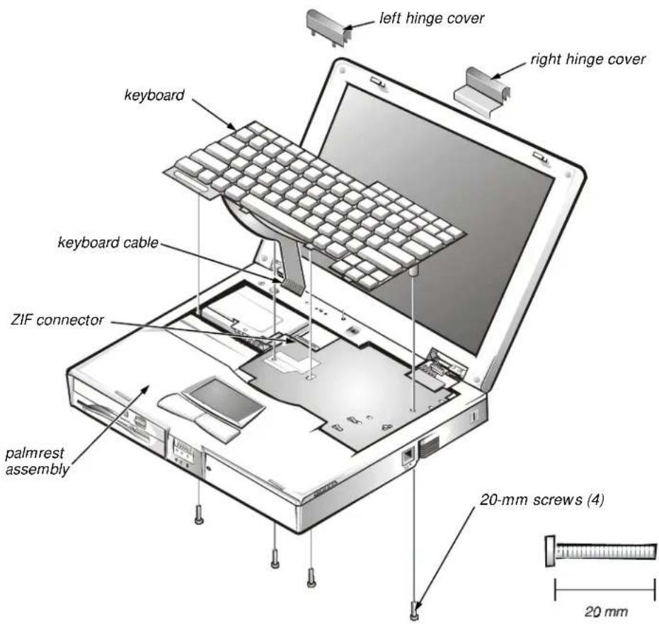
text_image
left hinge cover right hinge cover keyboard keyboard cable ZIF connector palmrest assembly 20-mm screws (4) 20 mmFigure 4-21. Keyboard Removal
To remove the keyboard, follow these steps (see Figure 4-21):
- Turn the computer over and remove the four 20-mm screws from the bottom of the computer.
- Turn the computer back over and open the display.
- Insert a small flat-blade screwdriver or scribe along the right top of the keyboard, just above the row of function keys. Working from right to left, free the keyboard by prying it toward the front of the unit. When free, lift the top of the keyboard slightly to clear the palmrest assembly.
- Slide the keyboard toward the display assembly to release the front edge of the keyboard from the palmrest assembly.
- Rotate the bottom of the keyboard up toward the display assembly to expose the keyboard cable.
- Disconnect the keyboard cable from ZIF connector JP14 on the system board. Use the pick to pry up the latches on each side of the connector.

CAUTION: Lift the cable away only after the ZIF connector is opened (see "ZIF Connectors" found earlier in this chapter). Pulling the cable from the connector damages the conductive coating on the end of the cable.
- Remove the keyboard from the palmrest assembly.
Thermal Shield and Internal Modem
The thermal shield serves as a heat shield for the system board, as well as an EMI fence for the processor board.
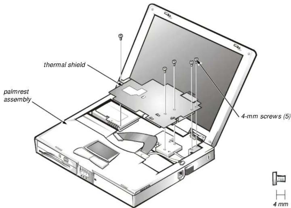
text_image
thermal shield palmrest assembly 4-mm screws (5) 4 mmFigure 4-22. Thermal Shield Removal
This procedure assumes that you have removed the keyboard. To remove the thermal shield, follow these steps (see Figure 4-22):
1. Remove the hinge covers.
Open the computer to 170 degrees, supporting the display assembly. From the outside edge of the unit, carefully insert a flat-blade screwdriver or scribe into the space on the inside of the hinge cover. Bring the tool against the front wall of the hinge cover and pull toward the keyboard to loosen the plastic snaps at the back of the hinge cover. Move the tool to the inside top of the hinge cover and lift the hinge cover off. If the hinge covers are tight, use a plastic wedge or scribe to loosen and pop them off.
Be careful not to accidentally turn on the computer when removing the left hinge cover.
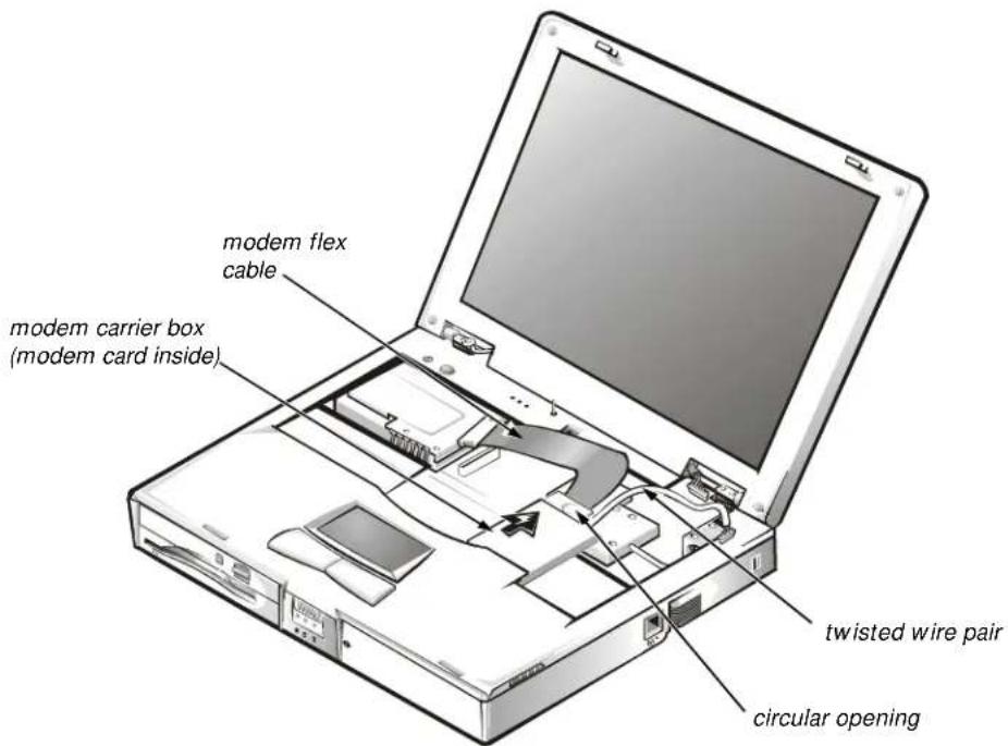
text_image
modem flex cable modem carrier box (modem card inside) twisted wire pair circular openingFigure 4-23. Modem Removal
- If your computer has an internal modem, disconnect the modem flex cable (see Figure 4-23) from connector JP20 on the system board and disconnect the twisted wire pair from connector JP2 on the RJ-11 card. Bend the cables back over the palmrest assembly to move them out of the way of the thermal shield.
- Remove the four flat-head 4-mm screws and the one K-head 4-mm screw securing the thermal shield. Note that the K-head screw is leftmost and is thicker than the other four.
- Remove the thermal shield from the palmrest assembly. Note that the bottom of the shield has an EMI fence that surrounds the processor board.
- If needed, remove the two screws securing the EMI fingers to the thermal shield and remove the fingers.
- If you have an internal modem, remove it by inserting a screwdriver through the circular opening and pulling the modem carrier box carefully toward the back of the computer (see Figure 4-23). Lift the top off the metal carrier and remove the modem card if needed. Disconnect the flex cable from the modem card if needed.
Display Assembly and Components
This section describes how to remove the display assemblies shown in Figures 4-14 and 4-15 and gives removal and replacement procedures for the components of the display assembly.
The display assembly consists of the following components:
- Front bezel
• LCD panel and hinges - LCD brackets
- Carrier tray
- Inverter board
- Back cover
Display Assembly
This section provides the removal procedure for the display assembly.
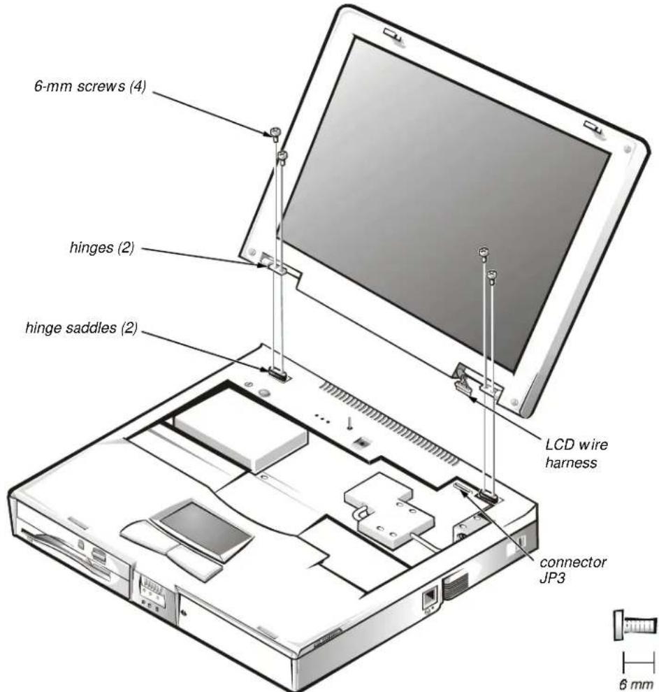
text_image
6-mm screws (4) hinges (2) hinge saddles (2) LCD wire harness connector JP3 6 mmFigure 4-24. Display Assembly Removal
This procedure assumes that you have removed the keyboard and thermal shield. To remove the display assembly from the computer, follow these steps (see Figure 4-24):
- Disconnect the LCD wire harness from connector JP3.
Use a dental pick or flat-blade screwdriver to pry up each end of the connector to release it.
-
Close the display.
-
Remove the four 6-mm screws that secure the two hinges.
-
Unlatch the display assembly and lift the assembly off the computer base.
Front Bezel
This section provides the removal procedure for the front bezel.
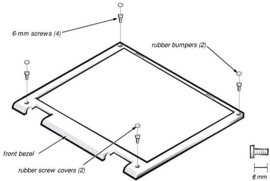
text_image
6-mm screws (4) rubber bumpers (2) front bezel rubber screw covers (2) 6 mmFigure 4-25. Front Bezel Removal
This procedure assumes that you have removed the display assembly from the computer base. To remove the front bezel, follow these steps (see Figure 4-25):
- Use a dental pick to pry the rubber screw covers off of the bottom two screws and the rubber bumpers off of the top two screws.
- Remove the four 6-mm screws from the front bezel.
- Unsnap the front bezel from the back cover and remove it from the assembly.
Carefully insert your fingers between the LCD panel and the bezel. Roll the plastic up slightly to insert your fingers further in, and then lift upward to free the snaps. Start at the middle bottom and then work around.
When replacing the bezel, ensure that the LCD wire harness is routed correctly through the openings in the back cover and is not pinched.
13.3-Inch LCD Panel
This section provides the removal procedure for the 13.3-inch LCD panel.
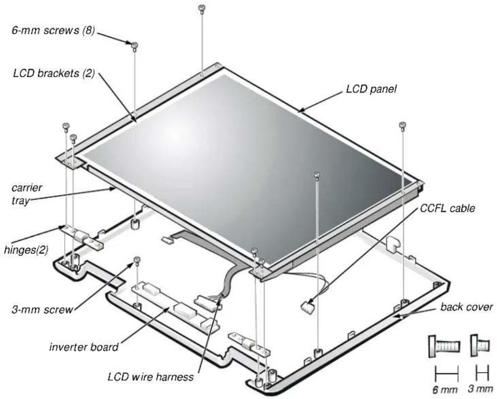
text_image
6-mm screws (8) LCD brackets (2) LCD panel carrier tray hinges(2) 3-mm screw inverter board LCD wire harness CCFL cable back cover 6 mm 3 mmFigure 4-26. 13.3-Inch LCD Panel Removal
This procedure assumes that you have removed the front bezel. Follow these steps to remove the 13.3-inch LCD panel (see Figure 4-26):
-
Remove the eight 6-mm screws that secure the left and right LCD brackets to the front plastic cover.
-
Detach the LCD wire harness from connector CN2 on the right side of inverter board.
-
If present, carefully remove the grounding tape between the inverter board and LCD panel.
-
Loosen the 3-mm screw securing the inverter board.
-
Lift the LCD panel, LCD brackets, and carrier tray, as a unit, out of the back cover.
Rotate upward from the bottom of the panel because the top slides underneath the plastic hooks.
- Remove the hinges, which were previously held in place by pressure and screws.
To remove the inverter board, follow these steps:
- Remove the 3-mm screw securing the inverter board to the back cover.
- If you have not removed the LCD panel, disconnect the LCD wire harness from connectors CN1 and CN2 on the inverter board.
- Remove the inverter board from the back cover.
13.3-Inch LCD Brackets and Carrier Tray
This section provides the removal procedure for the LCD brackets and carrier tray from the 13.3-inch LCD panel.
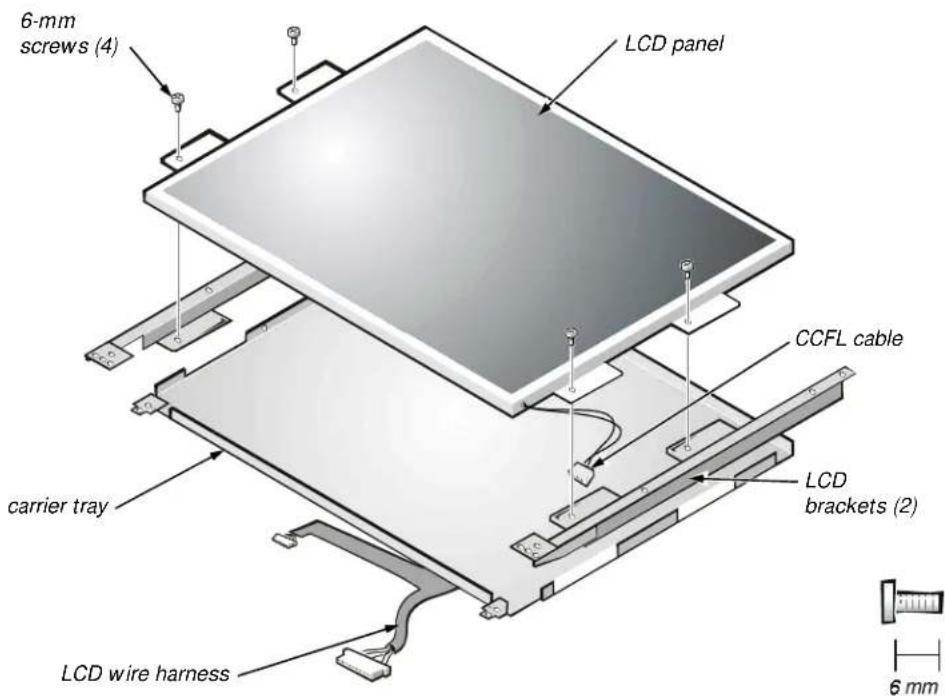
text_image
6-mm screws (4) LCD panel CCFL cable carrier tray LCD brackets (2) LCD wire harness 6 mmFigure 4-27. 13.3-Inch LCD Brackets and Carrier Tray Removal

CAUTION: The metal on the carrier tray is sharp. Be careful not to cut yourself.
This procedure assumes that you have removed the front bezel and the 13.3-inch LCD panel. To remove the brackets from the LCD panel, follow these steps (see Figure 4-27):
- Detach the LCD wire harness from connector CN1 on the top left side of the inverter board
- Remove the four 6-mm screws from the sides of the mounting brackets.
- Remove the brackets from the LCD panel.
To remove the 13.3-inch LCD panel from the carrier tray, follow these steps:
- Remove any Kapton tape covering the CCFL cable.
- Gently pull the cable out of its connector.
- Remove any Kapton tape from the LCD wire harness.
- Disconnect the LCD wire harness from the LCD panel.
- Lift the LCD panel out of the carrier tray.
14.1-Inch LCD Panel, Brackets, and Carrier Tray
This section provides the removal procedure for the LCD panel, LCD brackets, and carrier tray for the 14.1-inch display assembly.
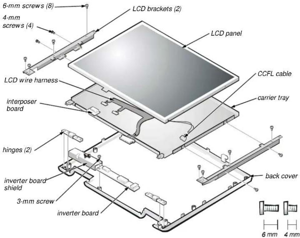
text_image
6-mm screws (8) 4-mm screws (4) LCD brackets (2) LCD panel LCD wire harness interposer board hinges (2) inverter board shield 3-mm screw inverter board CCFL cable carrier tray back cover 6 mm 4 mmFigure 4-28. 14.1-Inch LCD Panel Removal
This procedure assumes that you have removed the front bezel. Follow these steps to remove the 14.1-inch LCD panel (see Figure 4-28):
- Remove the eight 6-mm screws that secure the left and right LCD brackets to the front plastic cover.
- Detach the CCFL cable from connector CN2 on the right side of inverter board.
- Carefully remove the grounding tape between the inverter board and LCD panel.
- Remove the 3-mm screw securing the inverter board, and unsnap the inverter board from the back cover.
- Lift the LCD panel, LCD brackets, and inverter board as one unit out of the back cover.
Rotate upward from the bottom of the panel because the top slides underneath the plastic hooks.
- Remove the hinges, which were previously held in place by pressure and screws.
To remove the LCD brackets from the LCD panel, follow these steps:
- Remove the four 4-mm screws from the sides of the LCD brackets.
- Remove the brackets from the LCD panel.
CAUTION: The metal on the carrier tray is sharp. Be careful not to cut yourself.
To remove the LCD panel from the carrier tray, follow these steps:
- Lift the inverter board shield, pull it slightly away from the panel to expose the cabling, and detach the LCD wire harness from connector CN1 on the inverter board.
- Remove any Kapton tape covering the CCFL cable on the back of the LCD.
- Gently pull the interposer board off the connector to the LCD panel.
- Lift the LCD panel up and remove any tape between the LCD wire harness and the carrier tray.
- Disconnect the LCD wire harness from the LCD panel.
- Lift the LCD panel out of the carrier tray.
- Disconnect the LCD wire harness from the LCD panel.

Palmrest Assembly and Components
This section describes how to remove the palmrest assembly. The palmrest assembly consists of the following components (see Figure 4-16):
- MPEG-2 card
- IR board
• Hard-disk drive heat shield - Touch pad assembly
- Speakers
MPEG-2 Card
This section provides the removal procedure for the MPEG-2 card, if present.
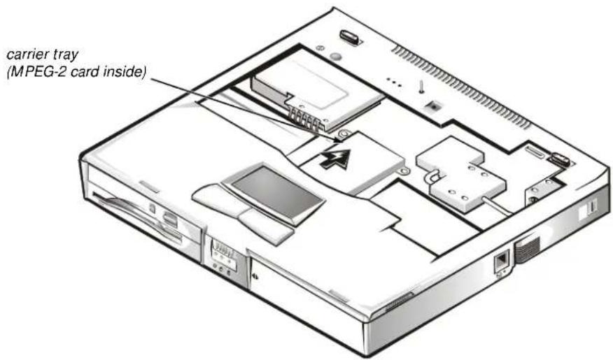
text_image
carrier tray (MPEG-2 card inside)Figure 4-29. MPEG-2 Card Removal
To remove the MPEG-2 card, follow these steps (see Figure 4-29):
-
Gently pull the carrier tray off of connector JP19 on the system board. Do not rock the card to remove it, because this may damage the connectors.
-
Remove the carrier tray by sliding it toward the back of the computer
-
Remove the MPEG-2 card from the carrier tray.
Palmrest Assembly
This section provides the removal procedure for the palmrest assembly.
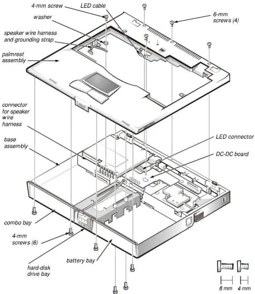
text_image
4-mm screw LED cable washer speaker wire harness and grounding strap palmrest assembly connector for speaker wire harness base assembly LED connector DC-DC board combo bay 4-mm screws (6) hard-disk drive bay battery bay 6 mm 4 mmFigure 4-30. Palmrest Assembly Removal
This procedure assumes that you have removed the keyboard, thermal shield, and display assembly. To remove the palmrest assembly, follow these steps (see Figure 4-30):
- Turn the unit over and place it face down.
- Remove the two 4-mm screws from the top inside of the combo bay.
- Remove the two 4-mm screws from the top inside of the battery bay.
-
Remove the two 4-mm screws from the top inside of the hard-disk drive bay.
-
Turn the unit back over.
- Remove the three 6-mm screws from the top of the base assembly, along the back edge.
- Remove the 6-mm screw from the DC-DC board.
- Remove the 4-mm screw and the washer securing the grounding strap to the PC Card heat shield.
- Disconnect the speaker wire harness from connector JP18 on the left side of the system board.
This wire harness also contains wiring for the touch pad and the touch pad buttons.
-
Disconnect the LED cable from connector JP10 on the system board.
-
Remove the palmrest assembly from the base assembly.
Start at the back right of the computer and move forward around the computer. Carefully lift the palmrest assembly up and pull it forward to unsnap the hidden tabs spaced around the sides and along the top of the battery bay and options bay.
When replacing the palmrest assembly, orient the assembly in its original position on the base assembly and press firmly near each tab until the palmrest assembly snaps into place. Start at the front to align those tabs first. Make sure that all the tabs are aligned.
The following subsections provide removal and replacement procedures for the components of the palmrest assembly.
IR Board
The IR board (see Figure 4-31) controls the power button, lid switch, microphone, and lights on the indicator panel above the keyboard.
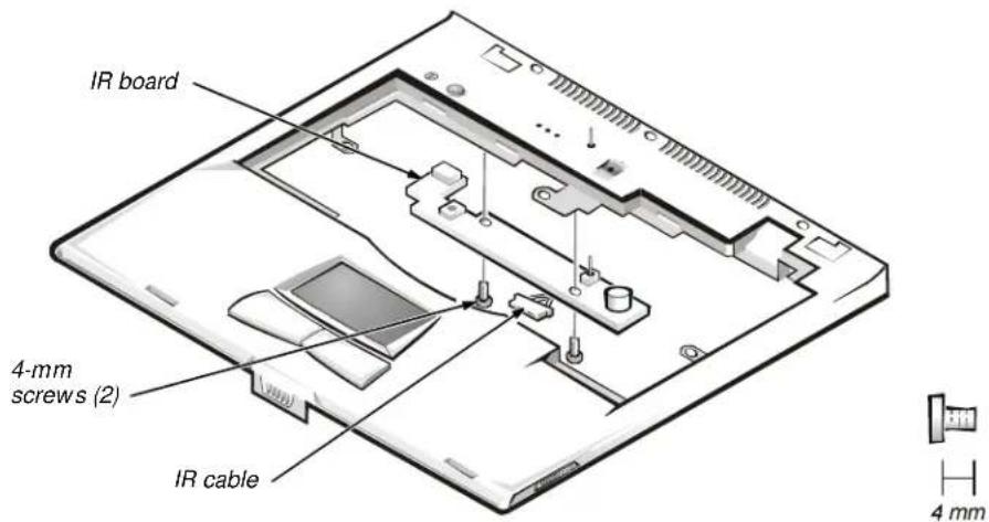
text_image
IR board 4-mm screws (2) IR cable 4 mmFigure 4-31. IR Board Removal
This procedure assumes that you have removed the palmrest assembly from the base assembly. To remove the IR board, follow these steps:
- Remove the two 4-mm screws securing the IR board.
- Disconnect the IR cable from connector JP2 on the IR board.
- Remove the IR board.
Hard-Disk Drive Heat Shield
This section provides the removal procedure for the hard-disk drive heat shield.
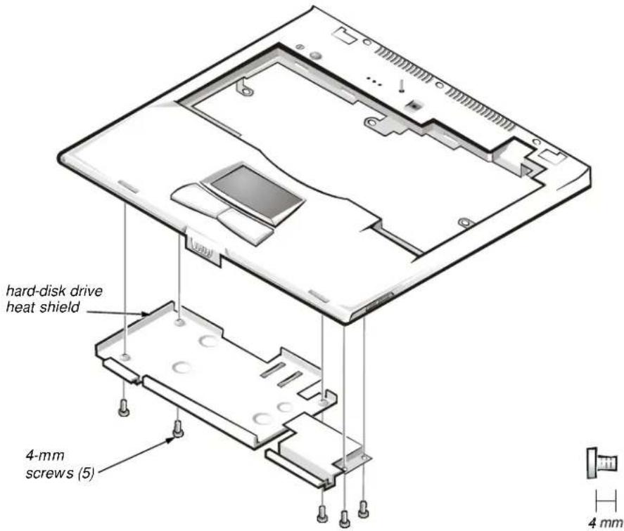
text_image
hard-disk drive heat shield 4-mm screws (5) 4 mmFigure 4-32. Hard-Disk Drive Heat Shield Removal
This procedure assumes that you have removed the palmrest assembly from the base assembly. To remove the hard-disk drive heat shield, follow these steps (see Figure 4-32):
- Place the palmrest assembly face down.
- Remove the five 4-mm screws securing the hard-disk drive heat shield.
- Remove the hard-disk drive heat shield.
Touch Pad Assembly
This section provides the removal procedure for the touch pad assembly.
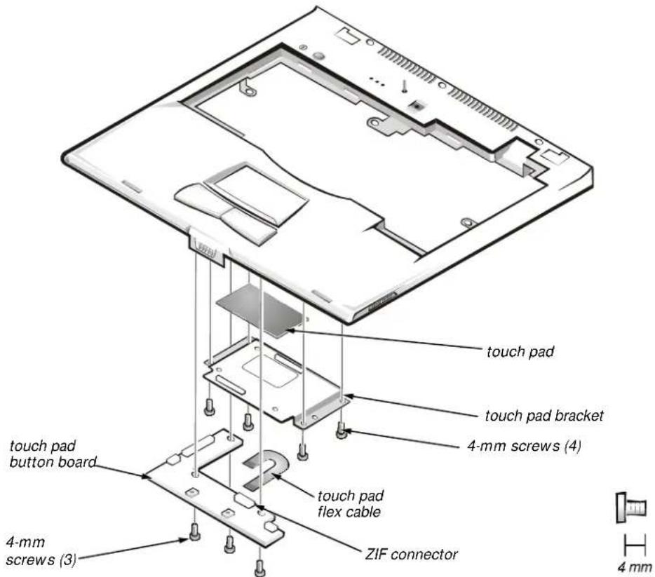
text_image
touch pad touch pad bracket 4-mm screws (4) touch pad button board touch pad flex cable 4-mm screws (3) ZIF connector 4 mmFigure 4-33. Touch Pad Assembly Removal
This procedure assumes that you have removed the palmrest assembly from the base assembly and that you have removed the hard-disk drive heat shield. To remove the touch pad assembly, follow these steps (see Figure 4-33):
- Remove the three 4-mm screws securing the touch pad button board.
- Disconnect the two speaker cables from connectors JP5 and JP3 on the touch pad button board.
- Disconnect the speaker wire harness from connector JP1 on the touch pad button board.
- Disconnect the touch pad flex cable from ZIF connector JP4 on the touch pad button board. Use the pick to pry up the latches on each side of the connector.

CAUTION: Lift away the cable only after the ZIF connector is opened (see "ZIF Connectors" found earlier in this chapter). Pulling the cable from the connector damages the conductive coating on the end of the cable.
- Disconnect the touch pad flex cable from ZIF connector J1 on the touch pad. Use the pick to pry up the brown center piece on the connector.

CAUTION: Lift away the cable only after the ZIF connector is opened (see "ZIF Connectors" found earlier in this chapter). Pulling the cable from the connector damages the conductive coating on the end of the cable.
- Remove the touch pad button board.
- Remove the four 4-mm screws securing the touch pad bracket.
- Remove the touch pad bracket.
- Remove the touch pad.
The touch pad buttons are heat-staked into the palmrest assembly and are not removable.
Speakers
This section provides the removal procedure for the speakers.
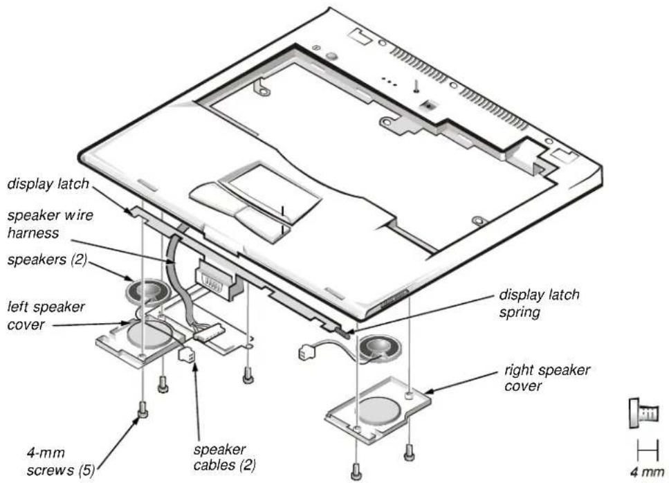
text_image
display latch speaker wire harness speakers (2) left speaker cover 4-mm screws (5) speaker cables (2) display latch spring right speaker cover 4 mmFigure 4-34. Speaker Removal
This procedure assumes that you have removed the palmrest assembly from the base assembly and that you have removed the hard-disk drive heat shield and touch pad assembly. To remove the speakers, follow these steps (see Figure 4-34):
- Remove any tape securing the speaker cables.
- Remove the three 4-mm screws securing the left speaker cover.

NOTE: Before removing the speaker cables and wire harness, be sure to note their routing through the slots and pins so you can correctly reinstall the components.
-
Remove the left speaker cover, speaker, and speaker cable.
-
Remove the speaker wire harness.
-
Remove the two 4-mm screws securing the right speaker cover.
-
Remove the right speaker cover, speaker, and speaker cable.
The display latch is no longer secured by the speaker covers. Be careful not to lose the spring.
- Remove the display latch and spring.
To replace the speaker, resolder the speaker cable to the new speaker.
When reinstalling the speakers, be especially careful to route the speaker cables and speaker wire harness through the appropriate slots and pins.
Base Assembly and Components
The following subsections provide removal and replacement procedures for most components of the base assembly. The procedures in these subsections assume that the keyboard, thermal shield, display assembly, and palmrest assembly have been removed.
The base assembly consists of the following components:
- PC Card heat sink
- Heat exchanger/fan
- DC-DC board
• LVDS board
• RJ-11 card - Processor board and memory module
- Hinge saddles
- System board
- PC Card cage
• Audio board and audio thermal shield - Latch assembly
•Kensington lock - Bottom case
PC Card Heat Sink
This section provides the removal procedure for the PC Card heat sink.
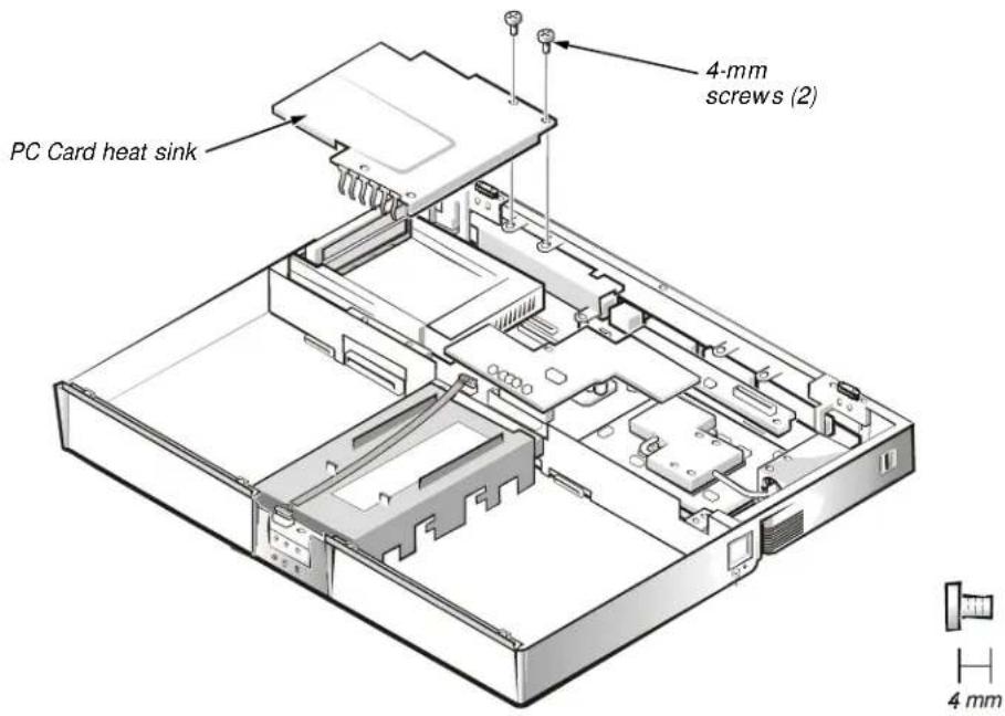
text_image
PC Card heat sink 4-mm screws (2) 4 mmFigure 4-35. PC Card Heat Sink Removal
To remove the PC Card heat sink, follow these steps (see Figure 4-35):
- Remove the two 4-mm screws securing the PC Card heat sink.
- Remove the heat sink.
Heat Exchanger/Fan
This section provides the removal procedure for the heat exchanger/fan.
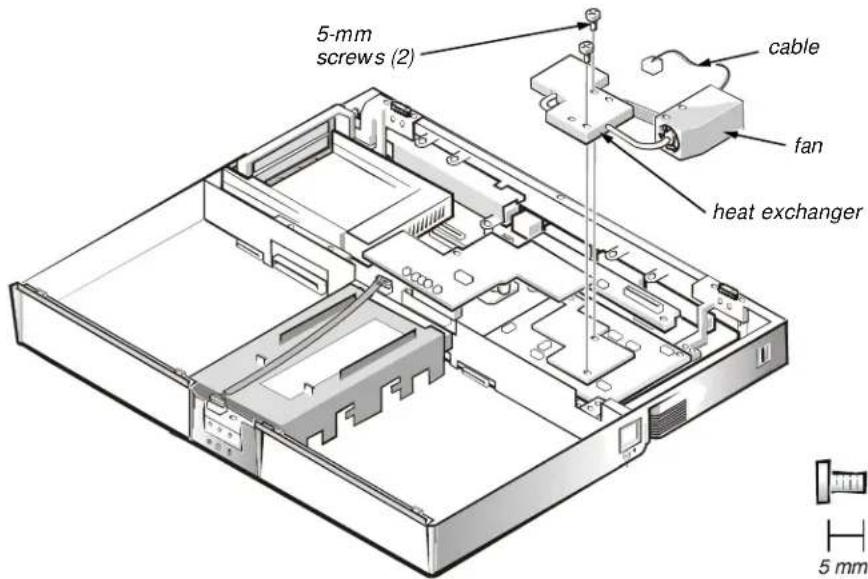
text_image
5-mm screws (2) cable fan heat exchanger 5 mmFigure 4-36. Heat Exchanger/Fan Removal
To remove the heat exchanger/fan, follow these steps (see Figure 4-36):
- Remove the two 5-mm screws securing the heat exchanger.
- Disconnect the fan cable from connector JP17 on the system board.
- Remove the heat exchanger/fan.
- Inspect the two thermal pads on the bottom of the heat exchanger and replace them if necessary.
When reinstalling the heat exchanger/fan, be sure to reconnect the fan cable to JP17; if you have an internal modem, there is an identical connector (JP2) next to JP17.
The heat exchanger/fan can be removed without removing the palmrest assembly.
- Remove the two 5-mm screws securing the heat exchanger.
- Disconnect the fan cable from connector JP17 on the system board.
- Lift the heat exchanger and rotate it upward.
- Slide the heat exchanger/fan toward the front of the computer until the fan is completely clear of the overhanging palmrest plastic.
- Lift the heat exchanger/fan out at an angle.
- Inspect the two thermal pads on the bottom of the heat exchanger and replace them if necessary.
DC-DC Board
This section provides the removal procedure for the DC-DC board.
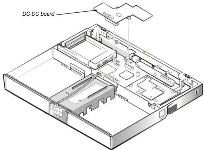
text_image
DC-DC boardFigure 4-37. DC-DC Board Removal
To remove the DC-DC board, gently pull the DC-DC board off of connectors JP11 and JP16 on the system board (see Figure 4-37). Do not rock the board to remove it, because this may damage the connectors.
LVDS Board
This section provides the removal procedure for the LVDS board.
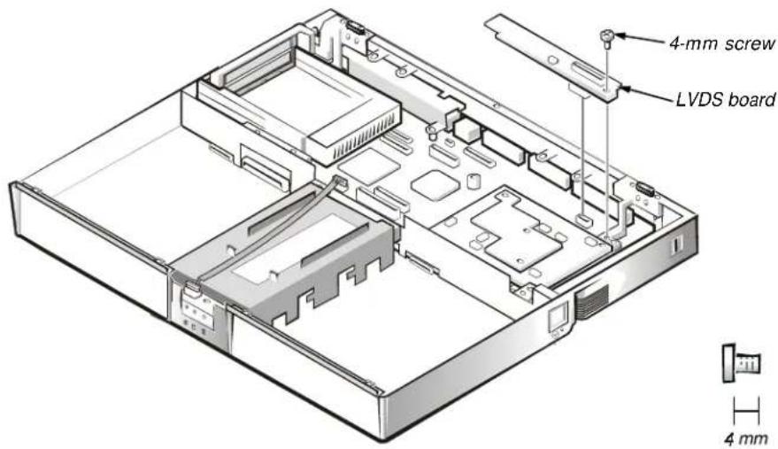
text_image
4-mm screw LVDS board 4 mmFigure 4-38. LVDS Board Removal
To remove the LVDS board, follow these steps (see Figure 4-38):
- Remove the 4-mm screw securing the LVDS board.
- Gently pull the LVDS board off of connectors JP9 and JP8 on the system board. Do not rock the board to remove it, because this may damage the connectors.
Processor Board and Memory Module
This section provides the removal procedure for the processor board and memory module. The processor board and memory module can be removed without removing the palmrest assembly.
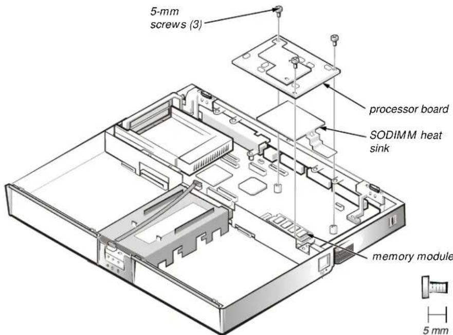
text_image
5-mm screws (3) processor board SODIMM heat sink memory module 5 mmFigure 4-39. Processor Board and Memory Module Removal
This procedure assumes that you have removed the heat exchanger/fan. To remove the processor board and memory module, follow these steps (see Figure 4-39):
- Remove the three 5-mm screws securing the processor board to the system board.
- Gently pull the processor board off of connector JP15 on the system board. Do not rock the board to remove it, because this may damage the connectors.
- Lift the SODIMM heat sink off of the memory module.
- Remove the memory module.
Carefully spread the inner metal tabs of the memory module socket to disengage the module from the socket. The module should pop up slightly. Then pull the memory module out of the socket.
- Inspect the thermal pad beneath the memory module to see if it needs replacement.
When reinstalling the SODIMM heat sink, be careful to align the hole in the SODIMM heat sink over the metal clip soldered to the system board.
When reinstalling the processor board, align the board with the notch on the system board connector. Press down on the left side of the board over the system board connector. This is the best spot to apply pressure to seat the processor correctly on connector JP15.
Hinge Saddles
This section provides the removal procedure for the hinge saddles.
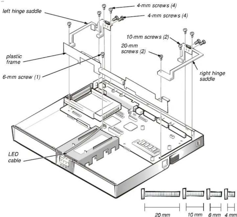
text_image
left hinge saddle 4-mm screws (4) 4-mm screws (4) 10-mm screws (2) 20-mm screws (2) 6-mm screw (1) right hinge saddle LED cable 20 mm 10 mm 6 mm 4 mmFigure 4-40. Hinge Saddle Removal
This procedure assumes that you have removed the PC Card heat sink and LVDS board. To remove the hinge saddles, follow these steps (see Figure 4-40):
- Remove the four 4-mm screws from the top of the left and right hinge saddles.
- Remove the four 4-mm screws from the back of the computer above the ports.
- Remove the 10-mm screw and 20-mm screw from the right hinge saddle and remove the saddle.
- Remove the 10-mm screw and 20-mm screw from the left hinge saddle and remove the saddle.
- Disconnect the LED cable from connector J6 on the system board.
- Remove the 6-mm screw from the plastic frame, remove any tape, and remove the plastic frame.
RJ-11 Card
This section provides the removal procedure for the RJ-11 card.
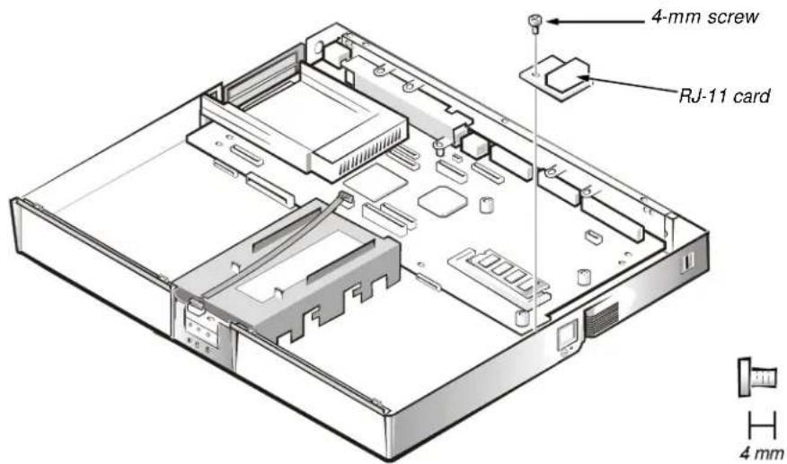
text_image
4-mm screw RJ-11 card 4 mmFigure 4-41. RJ-11 Card Removal
To remove the RJ-11 card, follow these steps (see Figure 4-41):
-
Remove the 4-mm screw securing the RJ-11 card to the system board.
-
Lift the card off the system board.
System Board
This section provides the removal procedure for the system board.
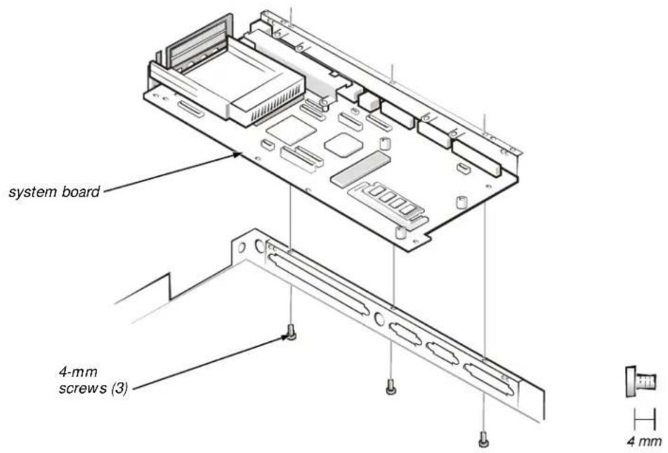
text_image
system board 4-mm screws (3) 4 mmFigure 4-42. System Board Removal
This procedure assumes that you have removed the PC Card heat sink, LVDS board, and hinge saddles. To remove the system board, follow these steps (see Figure 4-42):
- Remove the three 4-mm screws from the bottom of the computer.
- Remove the system board from the bottom case.
PC Card Cage
This section provides the removal procedure for the PC Card cage.
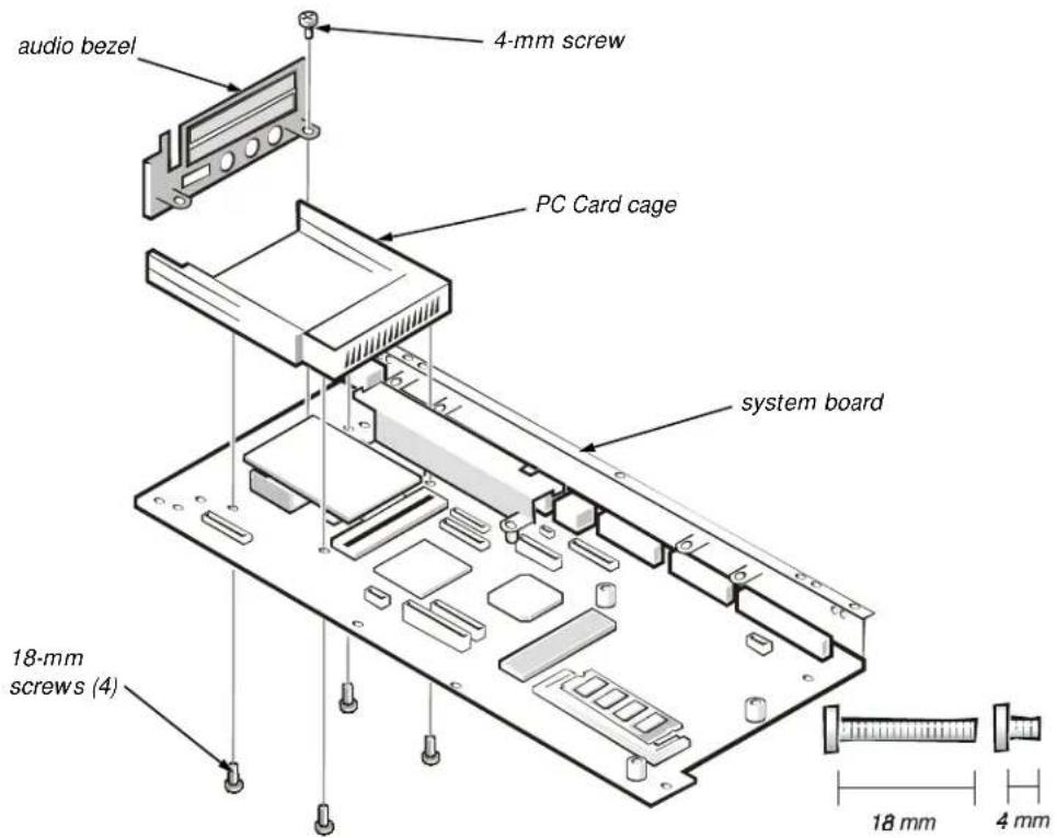
text_image
audio bezel 4-mm screw PC Card cage system board 18-mm screws (4) 18 mm 4 mmFigure 4-43. PC Card Cage Removal
This procedure assumes that you have removed the system board from the plastic case. To remove the PC Card cage, follow these steps (see Figure 4-43):
- Remove the 4-mm screw securing the audio bezel.
- Remove the audio bezel.
- Remove the four 18-mm screws securing the PC Card cage to the system board.
Use a support for the system board to prevent the board from flexing when the card cage screws are removed. - Gently pull the card cage off of connector UP9 on the system board. Do not rock the cage to remove it, because this may damage the connectors.
Replace the PC Card cage if it is damaged.
Audio Card and Audio Thermal Shield
This section provides the removal procedure for the audio card and audio thermal shield.
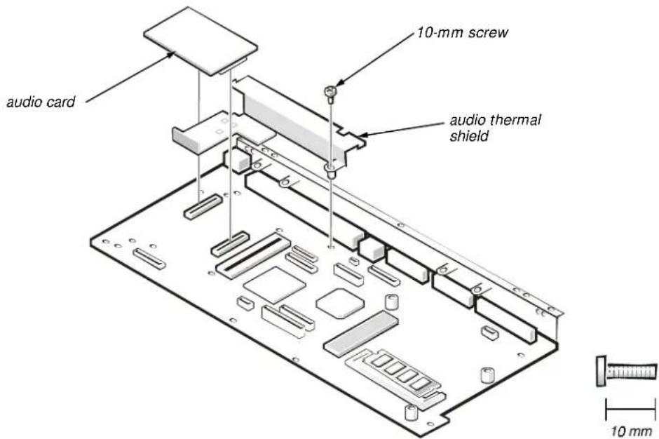
text_image
audio card 10-mm screw audio thermal shield 10 mmFigure 4-44. Audio Card and Audio Thermal Shield Removal
This procedure assumes that you have removed the system board from the plastic case and have removed the PC Card cage from the system board. To remove the audio card and audio thermal shield, follow these steps (see Figure 4-44):
- Gently pull the audio card off of connectors JP12 and JP13 on the system board. Do not rock the card to remove it, because this may damage the connectors.
- Remove the 10-mm screw securing the audio thermal shield, and then remove the shield.
Latch Assembly
This section provides the removal procedure for the latch assembly.
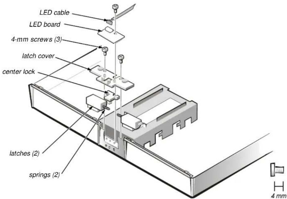
text_image
LED cable LED board 4-mm screws (3) latch cover center lock latches (2) springs (2) 4 mmFigure 4-45. Latch Assembly Removal
To remove the latch assembly, follow these steps (see Figure 4-45):
- Disconnect the LED cable from connector JP2 on the LED board.
-
Remove the 4-mm screw securing the LED board to the plastic base.
-
Remove the LED board.
-
Remove the two 4-mm screws holding the latch cover for the battery bay and options bay.
-
Remove the latch cover.
-
Remove the center lock over the two latches with springs.
-
Remove each spring and latch.
Be careful not to lose the small springs.
natural_image
Illustration of a closed book with a keyboard and a small object on top (no text or symbols)Index
A
AC adapter
connector, 1-2
removal, 4-3
audio
card removal, 4-64
jacks location, 1-3
thermal shield removal, 4-64
computer
exploded view, 4-10
features, 1-1
illustrated, 1-2
power, 1-5
technical specifications, 1-8
connectors
location, 1-3
B
base assembly exploded view, 4-14
battery
location, 1-2
location (options bay), 1-2
removal, 4-4, 4-8
battery charge gauge, 1-4
beep codes
during boot routine, 3-1
list of, 3-2
bezel
front removal, 4-38
boot routine
observing when troubleshooting, 2-4
C
carrier tray removal, 4-41
CD-ROM drive
disassembly, 4-29
location (options bay), 1-2
removal, 4-8
combo module
location, 4-8
removal, 4-8
D
DC-DC board removal, 4-56
Diagnostics Menu, 3-5
diskette drive
disassembly, 4-30
location (options bay), 1-2
display
close/suspend button, 1-2
latch, 1-2
location, 1-2
display assembly
13.1-inch LCD panel removal, 4-39
13.3-inch exploded view, 4-11
14.1-inch exploded view, 4-12
14.1-inch LCD panel removal, 4-42
carrier tray removal, 4-41
front bezel removal, 4-38
LCD bracket removal, 4-41
location, 4-36
removal, 4-37
DVD-ROM drive
disassembly, 4-29
E
eliminating resource conflicts, 2-5
error messages, 3-2, 3-5
expansion connector, 1-2
exploded views
13.3-inch display, 4-11
14.1-inch display, 4-12
base assembly, 4-14
computer, 4-10
palmrest assembly, 4-13
F
factory repair parts, list, 4-15
fan removal, 4-55
G
getting help, 2-5
H
hard-disk drive
disassembly, 4-28
heat shield removal, 4-49
location, 1-3
power management, 1-6
removal, 4-6
heat exchanger removal, 4-55
heat shield removal, 4-49
help, 2-5
hinge saddle removal, 4-60
1
I/O connector, illustrated, 1-2
indicator light location, 1-2
infrared
feature, 1-2
port location, 1-3
initial procedures
beep codes, 3-1
troubleshooting, 2-1
initialization
error messages, 3-5
interposer board, 4-12, 4-43
interrupt assignments
list of, 1-7
inverter board
removal, 4-40
IR board removal, 4-48
K
keyboard
location, 1-2
removal, 4-32
L
latch
assembly removal, 4-65
location, 1-2
LED board removal, 4-65
LVDS board removal, 4-57
M
main battery
location, 1-2
removal, 4-4
memory
maximum configuration, 1-1
system memory, 1-1
memory module
capacities supported, 1-1
removal, 4-7, 4-58
microphone location, 1-2
microprocessor, 1-1
slowing the microprocessor, 1-6
modem removal, 4-35
monitor connector, 1-2
MPEG-2 card removal, 4-45
0
options bay location, 1-2
P
palmrest assembly exploded view, 4-13 removal, 4-46
parallel connector, 1-2
PC Card cage removal, 4-63 heat sink removal, 4-54 removal, 4-5 slots, 1-3
physical description, 1-2
port replicator, 4-3, 4-4
POST beep codes about, 3-1 list of, 3-2
power button location, 1-2 computer, 1-5
power/suspend indicator, 1-2
precautionary measures, 4-2
processor board removal, 4-58
PS/2 connector, 1-2
R
removal and replacement procedures computer orientation, 4-1 precautionary measures, 4-2 recommended tools, 4-1
resource conflicts eliminating, 2-5
RJ-11 card removal, 4-61
s
screws identification, 4-2, 4-31 location template, 4-31
security cable slot, 1-3
serial connector, 1-2
speaker location, 1-2 removal, 4-52
specifications, technical, 1-8
status display panel about, 1-3, 1-4 location, 1-2
system features, 1-1 overview, 1-1 power, 1-5
system board removal, 4-62 system error messages Dell Diagnostics, 3-4 list of, 3-2
T
technical specifications, 1-8
thermal shield removal, 4-34
tools recommended, 4-1
touch pad assembly removal, 4-50 buttons, 1-2 location, 1-2
troubleshooting boot routine, 2-4 initial procedures, 2-1 initial user contact, 2-1 POST beep codes, 3-1 visual inspection, 2-2
U
USB connector, 1-2
user contact, initial, 2-1
Z
ZIF connectors
disconnecting, 4-8
reconnecting, 4-9
v
video card
removal, 4-7
visual inspection, 2-2