R1 - Subwoofer Roswell - Free user manual and instructions
Find the device manual for free R1 Roswell in PDF.


User questions about R1 Roswell
0 question about this device. Answer the ones you know or ask your own.
Ask a new question about this device
Download the instructions for your Subwoofer in PDF format for free! Find your manual R1 - Roswell and take your electronic device back in hand. On this page are published all the documents necessary for the use of your device. R1 by Roswell.
USER MANUAL R1 Roswell
Cybox Bluetooth Interface Installation Instructions
Cybox Parts & Hardware
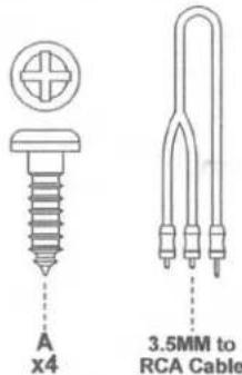
text_image
A x4 3.5MM to RCA CableTools Required



Electrical Tape

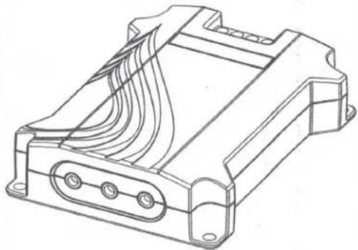
natural_image
Technical line drawing of a mechanical component with internal channels and mounting holes (no text or symbols)PLEASE NOTE: The Cybox Bluetooth device utilizes a line driver that produces a high voltage output to provide a top quality listening experience. If you intend on using the Cybox as an auxiliary input, please be aware that is has an integrated switch that can be used to lower the output voltage of the Cybox if necessary. See page 4 for more information.
INSTALLING THE CYBOX AS A STANDALONE UNIT

Disconnect positive cable(s) from battery/batteries. Tape the end(s) with electrical tape to prevent an accidental short circuit.


Find a suitable location to mount your Cybox. Ensure that it is installed in an area that will stay dry and keep the wires from being snagged or pulled out.
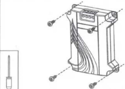
natural_image
Technical line drawing of a mechanical component with screwdriver and housing (no text or symbols)
Install a switch or locate an existing one to power on the Cybox. This 12V+ wire will run from the switch to the "R" terminal on the Cybox.

Connect the power wires as shown below:
| Cybox Port | Wire Colour | Function |
| B+ | Yellow | Constant 12V + |
| B- | Black | Ground |
| R | Red | Switched 12V+ |
| DR | Blue | Delayed remote to amplifier |
Please Note: The 12V+ should come from a 3a inline fuse. Note: Roswell recommends using marine-quality 18AWG wire for connecting to your Cybox. Ensure all wires are secure by giving each one a gentle pull after tightening.

Connect the Cybox to your amplifier using the supplied 3.5mm to RCA connector.
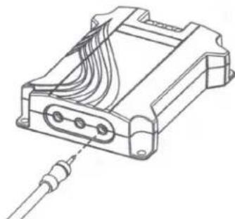
natural_image
Technical line drawing of an electronic device with cable and connector (no text or symbols)NOTE: If multiple amplifiers are being used you may purchase additional cables by calling your local Roswell Marine Audio Dealer and asking for part # C720-0003.

Verify that all wires are properly and securely connected. Reconnect the positive battery cable(s).
Turn on the switch installed for your Cybox.
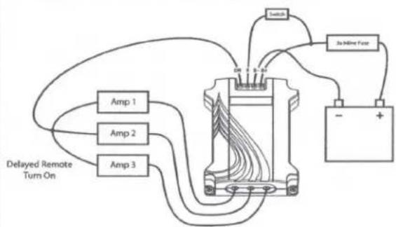
text_image
Switch Jia Online Fuse Amp 1 Amp 2 Amp 3 DIN 1 B-24 Delayed Remote Turn On - +STANDALONE UNIT
NOTE: to reduce the risk of a ground loop, which can negatively affect sound quality, please ensure the Cybox and all audio components share a common ground point.

PAIRING:
Open the Bluetooth settings on your device.
Scan for Bluetooth devices.
Choose "Roswell Cybox" on your device.
(You may see a MAC address or "MISC" before Roswell Cybox appears)
IMPORTANT: Make sure the volume is down on your device before playing music. Give the Cybox a few seconds before pressing "PLAY" on your device in order for the output to sync with the new connection. If you press "PLAY" too early there may be no sound.
You are now ready to listen to your music wirelessly via the Roswell Marine Audio Cybox.
INSTALLING THE CYBOX AS AN AUXILIARY-INPUT DEVICE
(Connected to a head unit or other receiver)

Disconnect positive cable(s) from battery or batteries. Tape the end(s) with electrical tape to prevent an accidental short circuit.


Find a suitable location to mount your Cybox. Ensure that it is installed in an area that will stay dry and keep the wires from being snagged or pulled out.
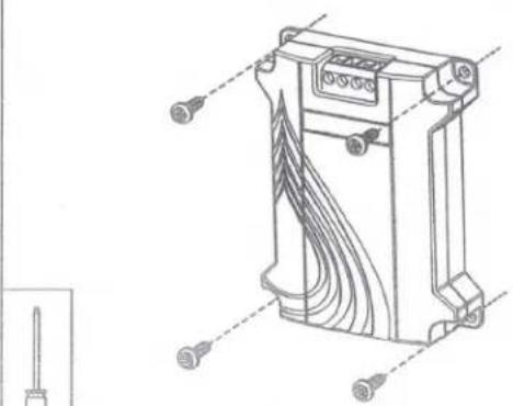
natural_image
Technical line drawing of a mechanical component with multiple screw holes and internal channels (no text or symbols)J
Connect the power wires as shown below:
Cybox Port
B+
B-
R
DR
Wire Colour
Yellow
Black
Blue
Empty
Function
Constant 12V +
Ground
Head Unit Remote
Please Note: The 12V+ should come from a 3a inline fuse. Note: Roswell recommends using marine-quality 18AWG wire for connecting to your Cybox. Ensure all wires are secure by giving each one a gentle pull after tightening.
K
Connect the Cybox to the head unit's auxiliary input RCAs using the supplied 3.5mm to RCA connector. Be sure the 3.5mm end is plugged into the correct leftmost output as shown below.

natural_image
Technical line drawing of an electronic component with a cable inserted (no text or symbols)Note: If your audio device utilizes a 3.5mm auxiliary input please use a 3.5mm to 3.5mm cable (not included) to make the connection.
L
Verify that all wires are properly and securely connected. Reconnect the positive battery cable(s).
Turn on the head unit and choose the correct source (auxiliary input).
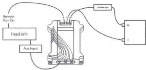
flowchart
graph TD
    A["Head Unit"] -->|Aux Input| B["24-holtage Input"]
    B --> C["I"]
    D["Remote Turn On"] --> A
    E["Ground"] --> B
AUXILIARY-INPUT DEVICE
NOTE: to reduce the risk of a ground loop, which can negatively affect sound quality, please ensure the Cybox and all audio components share a common ground point.
M
PAIRING:
Open the Bluetooth settings on your device.
Scan for Bluetooth devices.
Choose "Roswell Cybox" on your device.
(You may see a MAC address or "MISC" before Roswell Cybox appears)
IMPORTANT: Make sure the volume is down on your device before playing music. Give the Cybox a few seconds before pressing "PLAY" on your device in order for the output to sync with the new connection. If you press "PLAY" too early there may be no sound.
You are now ready to listen to your music wirelessly via the Roswell Marine Audio Cybox.
TROUBLESHOOTING:
I cannot pair my Cybox.
- Check to make sure the power wires are fully connected.
- Check to make sure Bluetooth connectivity is turned-on in your device.
- Make sure you have paired the Roswell Cybox.
- Make sure the distance between your device and the Cybox is not greater than 20 feet (6 M).
- Check to make sure that the Cybox is connected to your audio system.
I get a loud hissing noise from the auxiliary input setting on my head unit.
- Make sure the output switch is in the correct position. (See below)
- Make sure you are connected to the proper output on your Cybox. (See below)
There is no sound coming from my Audio System.
- Make sure the 3.5mm plug is fully inserted into to the jack on the Cybox.
- Confirm the device is paired with the "Roswell Cybox"
- Make sure you have selected the correct output on your device.
- Make sure you have the volume control at a suitable listening level.
Why can't I control the volume of the Cybox from my iPhone® 3G or 3GS using Bluetooth?
Make sure you have downloaded Apple® iOS4 software or later to your iPhone® 3G, 3GS and iPhone® 4.
For other inquiries please email Roswell Technical support at info@roswellwakeair.com
SWITCHING OUTPUT VOLTAGE
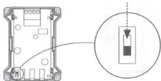
Open the housing of the Cybox by carefully squeezing the lower portion only on the sides and pulling the top portion up.
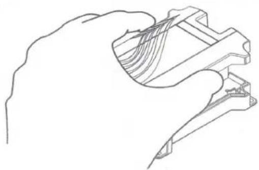
natural_image
Line drawing of a hand holding a mechanical component with internal threads (no text or symbols)Switch the output voltage switch to the down position. (This lowers the output voltage from your Cybox to the head unit to a usable level). Replace cover by snapping into place.
natural_image
Diagram of an electronic device showing a housing with internal components and a magnified inset highlighting a component (no text or symbols present)Note: The switch's default position is in the up position.
Note: Only the Stereo 3.5 mm output directly next to this switch is affected. USE THIS OUTPUT ONLY
SPECIFICATIONS
- Bluetooth 3.0
• Profiles Supported: aptX®, A2DP and AVRCP - Operates up to 33 feet (10 meters) from your portable device
• Output #1: Stereo 3.5MM Jack for Analog Audio Out
• Output #2: Stereo 3.5MM Jack for Analog Audio Out
• Output #3: Stereo 3.5MM Jack for Analog Audio Out (Switchable for use as an auxiliary input device)
• Dimensions of Cybox: 3.5" x 2.75" x 7/8"
SAFETY WARNINGS
- Do not expose the components of this product to direct moisture.
- Do not expose the components of this product to excessively high temperatures.
- Please keep out of reach of children.
- Please consult your owner's manual and/or local dealer if issues arise.
• This product must only be serviced by a qualified technician.
• Any improper use, alteration, and/or attempt to repair this product will void any expressed limited warranty.
DUAL ZONE
Volume Control
natural_image
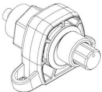
Technical line drawing of a mechanical housing component (no text or symbols)(FUN) - CTION
we design it, we build it, you enjoy it.
natural_image
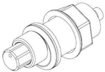
Technical line drawing of a mechanical component with threaded ends and flanges (no text or symbols)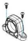
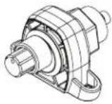
Surface Mount
Screw mount to a flat surface.
or
1

Flush Mount
Drill hole 7/8" Where you want your DZVC located.
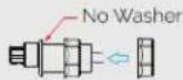

2
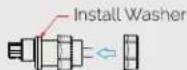
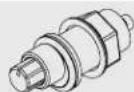
Run your DZVC through the mounting hole and install the backing nut. Once happy with orientation tighten the backing nut.
3
Enjoy your music to the fullest.
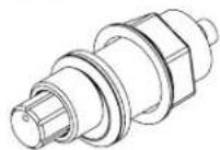
For installation assistance, email info@roswellmarine.com
EXAMPLE WIRING DIAGRAM
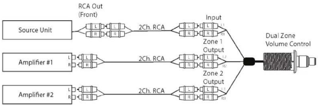
flowchart
graph LR
    A["Source Unit"] --> B["RCA Out (Front)"]
    B --> C["2Ch. RCA"]
    C --> D["Input"]
    D --> E["Dual Zone Volume Control"]
    F["Amplifier #1"] --> G["2Ch. RCA"]
    G --> H["Zone 1 Output"]
    G --> I["Zone 2 Output"]
    J["Amplifier #2"] --> K["2Ch. RCA"]
    K --> L["Zone 1 Output"]
    K --> M["Zone 2 Output"]
Welcome to the family.
www.roswellmarine.com
ROSWELL.
www.roswellmarine.com
R1
SPEAKER SERIES
natural_image
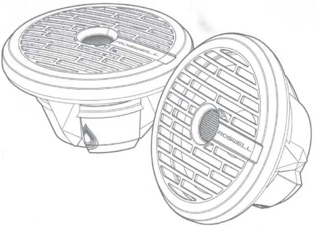
Technical line drawing of two Roswell speakers with mesh grating (no text or symbols)6.5"/8" Speaker Assembly Instructions
C920-1600 / C920-1601 / C920-1610 / C920-1611
ROSWELL.
Welcome to the family.
Thank you for purchasing the best marine speakers in the world. After years of development and testing, we are proud to introduce the R1 Series marine speakers, built to outlast - and outperform - every other marine speaker on the market. We at Roswell started a revolution in the wakeboard industry back in 1998, and have since expanded into marine audio and other branches of the marine industry. Even now, nearly 20 years later, we continue to push the boundaries.
We are fully committed to going past industry expectations every day to make your boating experience more enjoyable. With the input of our dealers, team riders, and boaters around the world, our goal remains to redefine the marine industry day in and day out. We will not be confined to our desks; we are out on the water testing our full line of products to ensure your days on the water are as hassle-free and enjoyable as possible.
The R1 Series is simply the latest iteration of that commitment. Thanks again for choosing Roswell and keep an eye out for more dominating technology throughout the season.
If you have any questions about your speakers or questions regarding installation, please contact your authorized Roswell dealer. If you have further questions, please don't hesitate to contact us directly at (321)-638-1331 OR by emailing support@roswellmarine.zendesk.com.
text_image
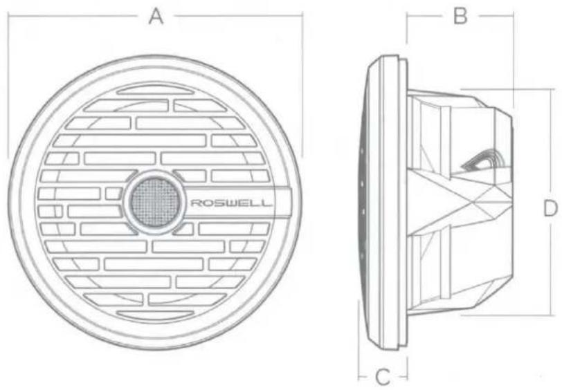
A B D C ROSWEEL| DESCRIPTION | 6.5" SPECS | 8" SPECS |
| A (overall diameter) | 6.81" / 173 mm | 9.21" / 234 mm |
| B (mounting depth) | 3" / 76 mm | 3.325" / 85 mm |
| C (grill height) | 1.2" / 30 mm | 1.5" / 38 mm |
| D (basket diameter) | 5.25" / 133 mm | 7.09" / 180 mm |
| Nominal Impedance | 4Ω | 4Ω |
| Frequency Response | 60 Hz - 20 kHz +/- 3dB | 50 HZ - 20 KHZ +/- 3dB |
| Power | 80 Watts RMS | 100 Watts RMS |
| Sensitivity | 90 dB @ 1W/1M | 90 dB @ 1W/1M |
FEATURES:
- Plug and play installation
• Integrated 12 dB/Oct. Crossover Network - Integrated flying lead connection for easy installation in tight spaces
- Integrated RGB LED with controller option
- Locking trim ring conceals all hardware
• Centrex plastic for true marine durability
• ASTM Salt Fog Spray Tested - 500 Hours
• ASTM UV Tested- 500 Hours - Klippel-certified for Guaranteed Performance
| PACKAGE CONTENTS | ||||
 |  |  |  |  |
| A x2 | B x2 | C x1 | D x8 | E x1 |
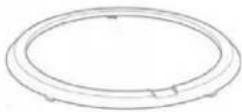
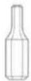
| R1 Series Speakers | Locking trim rings | Cut out template | Hex-head stainless screws | 3mm hex-head bit |
PREPARATION
- For safety, turn off the audio system and battery switch prior to beginning installation. If your vessel does not have a battery switch, simply disconnect the negative lead from the battery terminal.
- Use extreme caution before cutting and drilling holes to avoid damaging fuel lines, hydraulic lines, or existing electrical components.
- If additional wiring is required, we recommend using at least 18 gauge wiring and running all wires prior to installing the speaker. Longer runs may require 16 gauge wire to prevent negative impacts on sound quality. Leave some slack in the wire to allow for easier installation and to prevent tension on the wire.
- Avoid running wires near sharp edged surfaces. Never run wires exposed on the deck, protecting the wires behind cover offers the best protection from marine elements. If wires must be routed through metal or fiberglass walls, use rubber grommets to protect the wire.
- All wiring should be done by a qualified marine technician.
NOTE: Consider how you would like to use the integrated RGB LED before you begin installation. It can either be hard-wired to one of 7 different colors OR you may purchase an LED controller to allow any combination of colors and patterns.

WARNING

These speakers are capable of easily producing sound pressure levels (SPL) in excess of 100 dB, even in an open-air environment like a boat. Sound pressures at or above these levels can easily cause permanent hearing damage or loss. Be sure to use safe listening practices and protect your ears.
TOOLS REQUIRED

Dust Mask

Safety
Glasses

Power Drill

Air-saw
natural_image
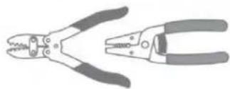
Illustration of two different types of pliers (no text or symbols present)Wire Strippers / Crimps
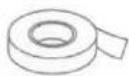
Masking Tape

Center Punch

Pen / Pencil

1/8" & 3/8"
Drill Bit

Countersink
Bit

18 AWG (Red) Heat Shrink Butt Splices (if not using the OEM quick-connect)
INSTRUCTIONS
Follow these illustrated steps to ensure proper installation of your R1 Series Speakers. Note: Required tools for each step are listed in the left column under each steps letter.
A
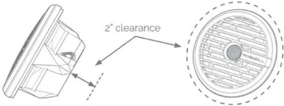
Locate a suitable area to mount the speaker in your vessel. Ensure the area is large enough to evenly mount the speaker and grill. Ensure the area behind the mounting area is spacious enough to allow proper fit and air flow.
text_image
2" clearance ROSWEELLB
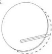
Use the cut out template (C) to locate and mark the area for the speakers.
natural_image
Simple line drawing of a circle with a dashed arc and a horizontal line inside, no text or symbols present.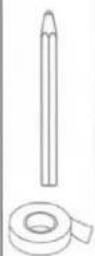
NOTE: If cutting through gelcoat/fiberglass, use extreme caution to avoid cracking the gelcoat. We recommend you tape off the entire area with low-tack masking tape. Cut slowly and carefully.
C
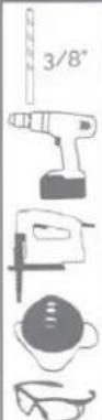
First use the 3/8" drill bit and drill to start the hole, then cut the mounting hole using jigsaw or air-saw.
natural_image
Simple line drawing of a stick inside a circle, no text or symbols present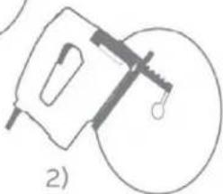
natural_image
Simple line drawing of a mechanical device with a circular base and lever mechanism (no text or symbols)D
text_image
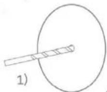
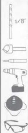
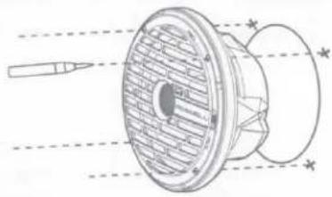
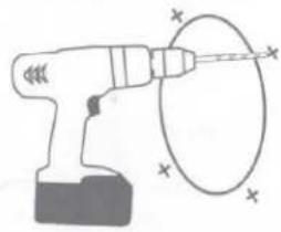
1/8'Remove the trim ring from the speaker first (refer to step G, turning in a counterclockwise direction instead). Place the speaker into the mounting cutout to ensure it will fit. Remove additional material if needed. Once the speaker fits properly, align the speaker to the desired orientation and use a center punch or pencil to mark the mounting holes for the screws to secure the speaker. Remove speaker from cutout and drill the holes with a 1/8" drill bit.
1)
natural_image
Technical line drawing of a mechanical component with cross-sectional view and dimension lines (no text or symbols)2)
natural_image
Illustration of a power tool emitting a circular arc with magnetic field lines (no text or symbols)NOTE: If drilling through fiberglass/gelcoat, be sure to run the drill in reverse until you are through the gelcoat, switch the drill into forward and finish drilling as normal. Then come back with a countersink bit and remove the gelcoat surrounding the hole. This will help avoid cracking/damaging the gelcoat around the mounting location.
E(i)
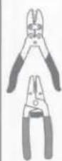
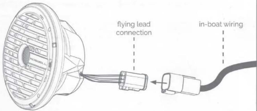
Make all connections from the flying lead harness to your in-boat wiring.
text_image
flying lead connection in-boat wiringE(ii)
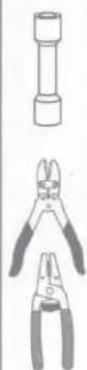
If you are not using the OEM quick-connect option, the wires may be cut and crimped as follows:
1)
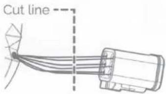
text_image
Cut line2)
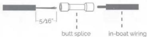
) Strip 5/16" of wires and connect to boat wiring using 18 AWG (Red) Heat Shrink Butt Splices
text_image
5/16" butt splice in-boat wiringF

natural_image
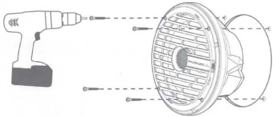
Illustration of four different types of screw and tool packages: screw, nut, bottle, and drill (no text or symbols)Using the included hex-head bit, secure the speaker to the mounting location using (4) hex-head screws per speaker.
text_image
Technical diagram of a Roswell electric drill with labeled components and screwdriver insertion instructionsG
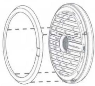
Install the trim ring by orienting the tabs and logo recess in the ring with the corresponding locations on the grill, fully inserting each tab and then gently rotating the ring into place by turning it in a clockwise motion.
natural_image
Technical line drawing of a mechanical component with concentric rings and a central circular feature (no text or symbols)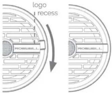
text_image
logo I recess ROSWEEL ROSWEELturn trim clockwise to lock
RECOMMENDED CROSSOVER SETTINGS
| 6.5" | 8" | |
| With Subwoofer | 90-100 Hz depending on Listening Preferences | 70-80 Hz depending on listening preferences |
| Without Subwoofer | 70-80 Hz depending on listening preferences | 50-60 Hz depending on listening preferences |
Gain setting will be dependent on output voltage of the head unit and RMS power of the amplifier used. Be careful when setting the amplifier and during listening sessions; burnt voice coils are not covered under warranty.
USE AND CARE
These speakers are built to the highest standards of marine durability. However, they are still a sensitive piece of electronic equipment. When cleaning, avoid hosing down the speakers directly. Simply wiping the speaker down with a damp cloth should be sufficient to ensure years of enjoyment.
ROSWELL LIMITED WARRANTY
Roswell warrants all new R1 Series Speakers against defects in material and workmanship for a period of TWO (2) YEARS from the original date of purchase. This warranty is not transferable and applies only to the original retail purchaser from an authorized Roswell retailer. Upon inspection by Roswell, should service be necessary under this warranty for any reason due to manufacturer defects, Roswell will, at our own discretion, repair or replace the defective product with new or similar conditioned product at no charge.
THIS WARRANTY DOES NOT COVER INSTALLATION OR DAMAGE RESULTING FROM ACCIDENT, MISUSE, ABUSE, IMPROPER WIRING, OPERATION OUTSIDE OF THE MANUFACTURERS RECOMMENDATIONS OR SPECIFICATIONS, OR AGAINST INSTRUCTIONS IN OWNERS MANUAL. IN ADDITION, ANY PRODUCT THAT HAS BEEN OPENED, TAMPERED WITH OR MODIFIED, OR IF ANY SERIAL NUMBERS HAVE BEEN REMOVED, WILL NOT BE COVERED BY ANY PART OF THE MANUFACTURES WARRANTY.
All warranty claims must first be made in direct contact with Roswell's warranty department. When first contact is made the warranty representative will issue an RA # to open a claim. All warranty returns should be sent to Roswell freight prepaid and must be accompanied by proof of purchase (a copy of original sales receipt). Direct returns from consumers or non-authorized retailers will be refused unless specifically authorized by Roswell with a valid return authorization number (RA#).
All warranty returns should be packed in the original packaging and must be accompanied by a copy of the original sales receipt. Product damage during shipping will not be covered under this warranty. The customer or retailer may choose to have this damage repaired at the normal "Out of Warranty" repair cost.
In no event will Roswell be liable for incidental, consequential, or other damages resulting from the use of this product. This includes but is not limited to, damage of hearing, property of person, damage based upon inconvenience or on loss of use of the product, and to the extent permitted by law, damages for personal injury.
This warranty applies to products being sold and used in the United States of America and Canada. In all other countries please contact your authorized Roswell representative.
For warranty and non-warranty repairs, please contact Roswell Global Inc.:
Phone: 1-321-638-1331
Email: warranty@roswellglobal.com
ROSWELL.
RGB RF REMOTE AND CONTROLLER KIT
USER MANUAL
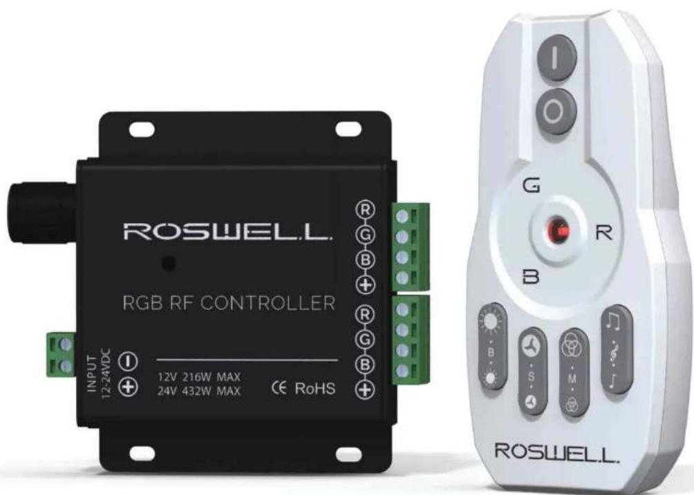
text_image
ROSWELL. RGB RF CONTROLLER INPUT 12V 216W MAX 24V 432W MAX CE RoHS G R B B S M ROSWELL.Rev 22-Aug-2016
PACKAGE CONTENTS:
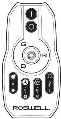
text_image
G R B B S M ROSWEELLRGB Remote
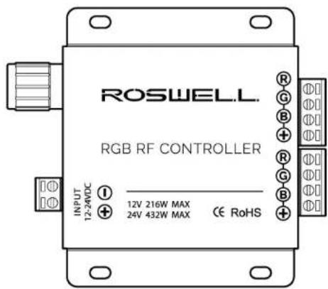
text_image
ROSWELL RGB RF CONTROLLER INPUT 12-24VDC I 12V 216W MAX 24V 432W MAX CE RoHSRGB Controller
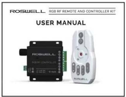
text_image
ROSWELL RGB RF REMOTE AND CONTROLLER KIT USER MANUAL ROSWELL RGB RF CONTROLLER 10.4GHz G B C H R ROSWELLManual

(2) AAA Batteries
Note: Pull plastic tab from battery compartment before use

natural_image
Pure electrical circuit lines without any symbolsAudio Splitter Cable - 3.5 mm audio (female) to (2) 3.5 mm audio (male)
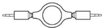
Extendable Auxiliary Cable - 3.5 mm audio (male) to 3.5 mm audio (male)
FEATURES:
• RF Control - max effective distance 65 ft/20 m
• Max. Power output - 432 W
• Capacitive touch control
• 3.5 mm audio input for music synchronization mode
• 20 Standard LED modes
• 15 Music synchronized modes
SPECIFICATIONS:
• Input voltage: DC12V\~24V
• Output power: Max 18A
• Volume control: 70 dB range
• Remote battery: (2) AAA
• Remote standby power consumption: 0.08mW
• Remote operating power consumption: 20mW
PRODUCT DIMENSIONS:
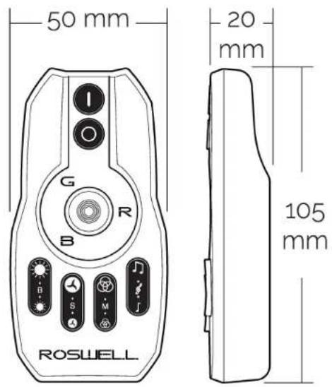
text_image
50 mm 20 mm 105 mm G R B B S M ROSWEELL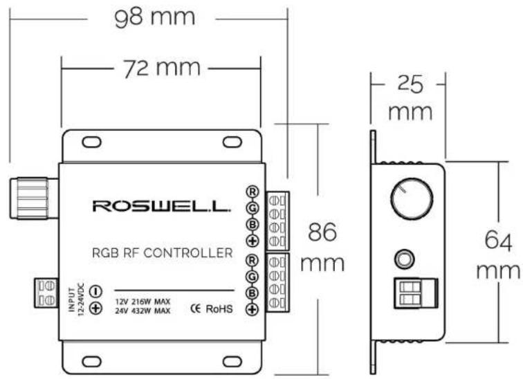
text_image
98 mm 72 mm ROSWEEL RGB RF CONTROLLER INPUT 12-24VDC 12V 216W MAX 24V 432W MAX CE RoHS 86 mm 25 mm 64 mmWIRING DIAGRAM:
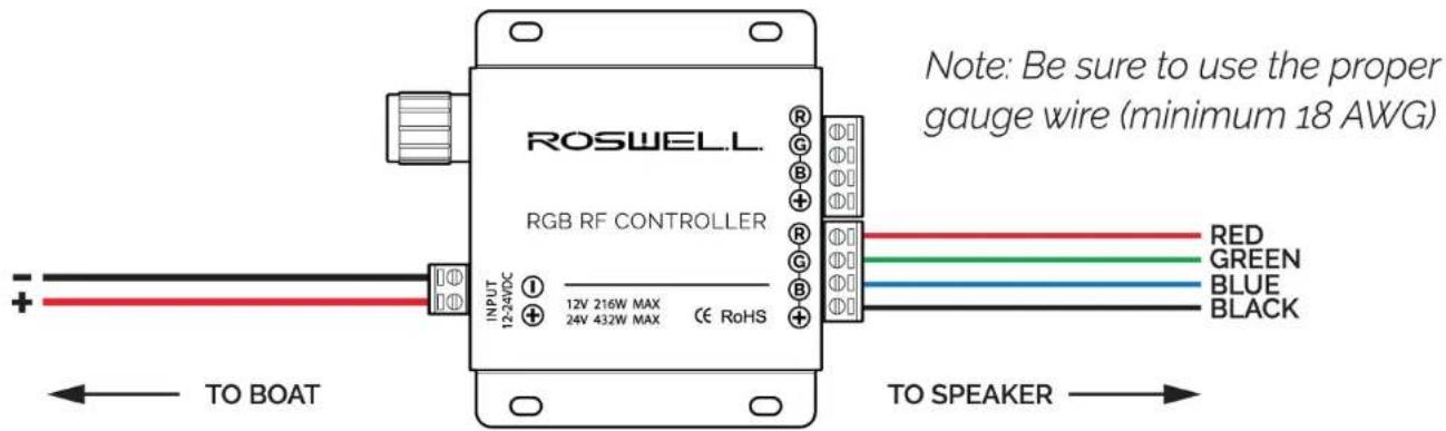
text_image
ROSWEEL. RGB RF CONTROLLER INPUT 12V 216W MAX 24V 432W MAX CE RoHS NOTE: Be sure to use the proper gauge wire (minimum 18 AWG) RED GREEN BLUE BLACK TO BOAT TO SPEAKERCOMPONENT FUNCTIONS:
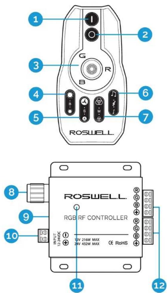
text_image
1 2 3 4 5 6 7 G R B B S M ROSWEELL 8 9 10 11 12 ROSWEELL RGB RF CONTROLLER INPUT 12V 216W MAX 24V 432W MAX CE RoHS1 ON/press for 3 seconds to switch to white lighting
2 OFF
3 LED color selector
4 Brightness control
5 Speed control
6 Mode control
7 Music mode switch
8 Sensitivity adjustment
9 3.5mm audio jack
10 Power input
11 Audio pickup microphone
12 RGB output
PROGRAMMED LED MODES:
Standard Modes
| No. | MODE | NOTE |
| 1 | Static Mode | 7 Colors |
| 2 | 7 Color Cycle | |
| 3 | RGB Crossfade | |
| 4 | 7 Color Crossfade | |
| 5 | Flashing Red | |
| 6 | Flashing Green | |
| 7 | Flashing Blue | Speed adjustable |
| 8 | Flashing Yellow | |
| 9 | Flashing Purple | |
| 10 | Flashing Cyan | |
| 11 | Flashing White | |
| 12 | Red/Green Crossfade | |
| 13 | Red/Blue Crossfade | |
| 14 | Green/Blue Crossfade |
Music Modes
| No. | MODE | NOTE |
| 1 | Red | |
| 2 | Green | |
| 3 | Blue | Brightness/Speed change with music |
| 4 | Purple | |
| 5 | Orange | |
| 6 | Cyan | |
| 7 | White | |
| 8 | 7 Color Cycle | |
| 9 | 7 Color Crossfade | |
| 10 | Flashing Red | Color/Brightness/Speed change with music |
| 11 | Flashing Green | |
| 12 | Flashing Blue | |
| 13 | Red/Green Crossfade | |
| 14 | Red/Blue Crossfade | |
| 15 | Green/Blue Crossfade |
Mic Mode
| NOTE |
| Mode switchingis still availablein MIC mode |
SAFETY WARNINGS:
- Do not expose the components of this product to direct moisture.
- Do not expose the components of this product to excessively high temperatures.
- Please keep out of reach of children.
- Please consult your owner's manual and/or local dealer if issues arise.
• This product must only be serviced by a qualified technician. - Any improper use, alteration, and/or attempt to repair this product will void any expressed limited warranty.
CONTROLLER BATTERIES:
- Do not mix alkaline, standard (carbon-zinc) and rechargeable batteries (Nickel Metal Hydride).
- Do not mix old and new batteries.
• Non-rechargeable batteries are not to be recharged. - Exhausted batteries should be removed immediately and must be recycled or disposed of properly according to state or local government ordinances and regulations.
• The supply terminals are not to be short-circuited. - Only batteries of the same or equivalent type as recommended are to be used.
- Batteries are to be inserted with the correct polarity.
- Do not dispose batteries in a fire - batteries may leak or explode.
ROSWELL LIMITED WARRANTY
Roswell warrants all new RGB RF Remote and Controller Kits against defects in material and workmanship for a period of ONE (1) YEAR from the original date of purchase. This warranty is not transferable and applies only to the original retail purchaser from an authorized Roswell retailer. Upon inspection by Roswell, should service be necessary under this warranty for any reason due to the manufacturer defect, Roswell will, at our own discretion, repair or replace the defective product with new or similar conditioned product at no charge.
THE WARRANTY DOES NOT COVER INSTALLATION OR DAMAGE RESULTING FROM ACCIDENT, MISUSE, ABUSE, IMPROPER WIRING, OPERATION OUTSIDE OF THE MANUFACTURERS RECOMMENDATIONS, OR SPECIFICATIONS, OR AGAINST INSTRUCTION IN OWNERS MANUAL. IN ADDITION, ANY PRODUCT THAT HAS BEEN OPENED, TAMPERED WITH OR MODIFIED, OR IF ANY SERIAL NUMBERS HAVE BEEN REMOVED, WILL NOT BE COVERED BY ANY PART OF THE MANUFACTURERS WARRANTY.
All warranty claims must first be made in direct contact with Roswell's warranty department. When first contact is made the warranty representative will issue an RA # to open a claim. All warranty returns should be sent to Roswell freight prepaid and must be accompanied by proof of purchase (a copy of original sales receipt). Direct returns from consumers or non-authorized retailers will be refused unless specifically authorized by Roswell with a valid return authorization number (RA#).
All warranty returns should be packed in the original packaging and must be accompanied by a copy of the original sales receipt. Product damage during shipping will not be covered under this warranty. The customer or retailer may choose to have this damage repaired at the normal "Out of Warranty" repair cost.
In no event will Roswell be liable for incidental, consequential, or other damages resulting from the use of this product. This includes but is not limited to, damage of hearing, property of person, damage based upon inconvenience or on loss of use of the product, and to the extent permitted by law, damages for personal injury.
This warranty applies to products being sold and used in the United States of America and Canada. In all other countries please contact your authorized Roswell representative.
For warranty and non-warranty repairs, please contact Roswell:
Phone: 1-321-638-1331
Email: warranty@roswellglobal.com
ROSWELL.
www.roswellmarine.com
R1
Amplifier
1000.1, 550.2, 650.4, & 900.6
Installation & Usage Instructions
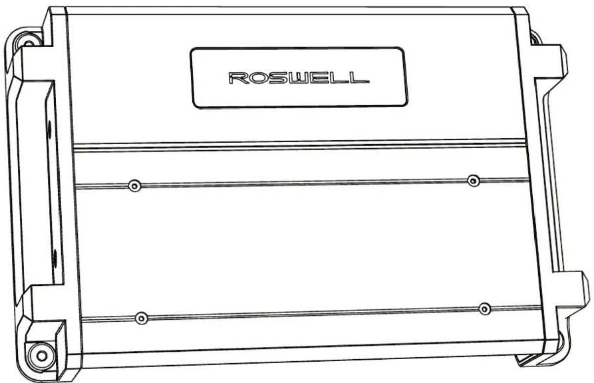
text_image
ROSWELLPart # C920-1831SD, C920-1832SD, C920-1834SD, C920-1836SD
Information: info@roswellmarine.com
If you have any questions please call : 1-321-638-1331
ROSWELL.
Welcome to the family.
Thank you for purchasing the best marine amp in the world. After years of development and testing, we are proud to introduce the R1 Series marine amplifiers, built to outlast - and outperform - every other marine amp on the market. We at Roswell started a revolution in the wakeboard industry back in 1998, and have since expanded into marine audio and other branches of the marine industry. Even now, nearly 20 years later, we continue to push the boundaries.
We are fully committed to going past industry expectations every day to make your boating experience more enjoyable. With the input of our dealers, team riders, and boaters around the world, our goal remains to redefine the marine industry day in and day out. We will not be confined to our desks; we are out on the water testing our full line of products to ensure your days on the water are as hassle-free and enjoyable as possible.
The R1 Series is simply the latest iteration of that commitment. Thanks again for choosing Roswell and keep an eye out for more dominating technology throughout the season.
If you have any questions about your speakers or questions regarding installation, please contact your authorized Roswell dealer. If you have further questions, please don't hesitate to contact us directly at (321)-638-1331 or by emailing info@roswellmarine.com.
Features
- Switchable Differential RCA inputs
• Calibrated Crossover Potentiometers
• 12 dB/oct. Crossover Slopes
• Bass boost control (0-18 dB @ 45 Hz) - Nickel-plated wire terminals
• Conformal coated PCBs
• Full 0-180° phase control (1000.1&550.2 only)
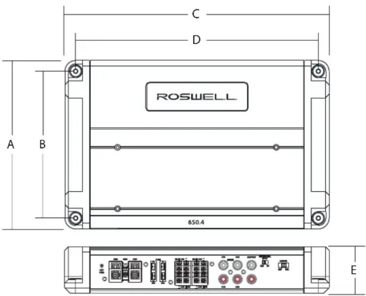
text_image
C D A B 650.4 ROSWELL EDescription 1000.1, 550.2, 650.4
900.6
| A (Overall Depth) 7.063" / 179mm | 7.063" / 179mm | |
| B (Mounting Bolt Pattern) | 6.180" / 157mm | 6.180" / 157mm |
| C (Overall Length) | 11.125" / 283mm | 13.661" / 347mm |
| D (Mounting Bolt Pattern) | 10.200" / 259mm | 12.953" / 329mm |
| E (Overall Height) | 1.900" / 48mm | 1.900" / 48mm |
1000.1
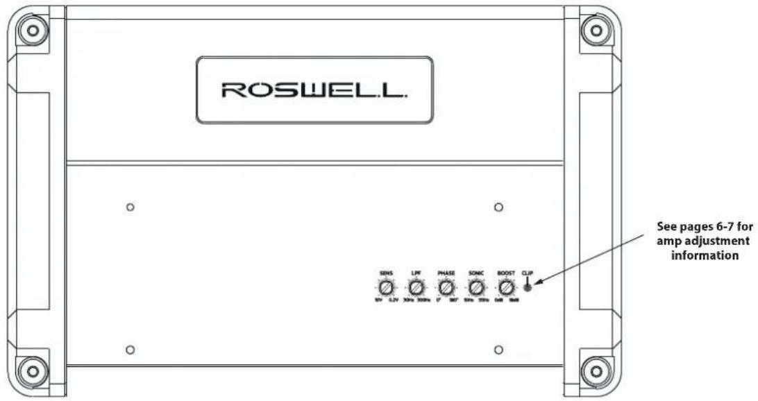
text_image
ROSWELL. SENS LIF PHASE SONC BOOST CLIP See pages 6-7 for amp adjustment information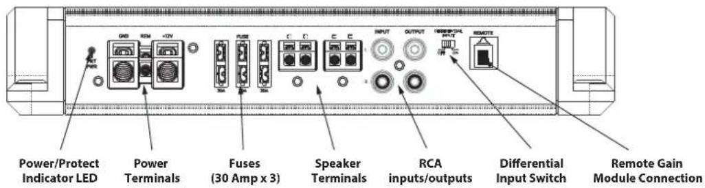
text_image
Power/Protect Indicator LED Power Terminals Fuses (30 Amp x 3) Speaker Terminals RCA inputs/outputs Differential Input Switch Remote Gain Module Connection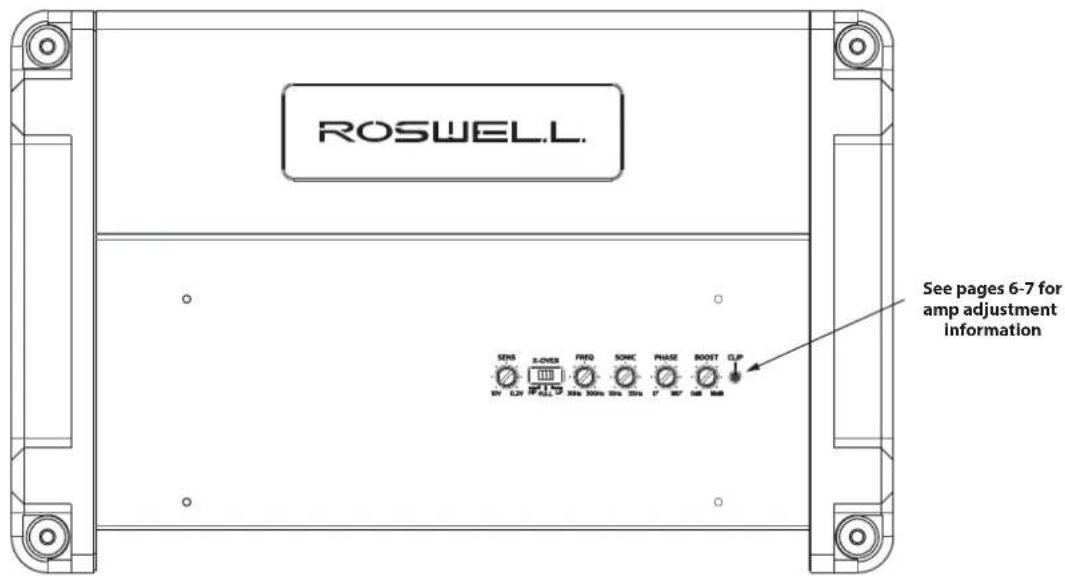
text_image
ROSWELL. See pages 6-7 for amp adjustment information SENS S-POWER RED SONG PHASE BOOST CLP 0V CLP FLSL LP 30Hz 300Hz 30Hz 30Hz 1" 0V 0dB 0dB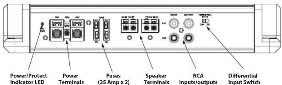
text_image
Power/Protect Indicator LED Power Terminals Fuses (25 Amp x 2) Speaker Terminals RCA inputs/outputs Differential Input Switch650.4
text_image
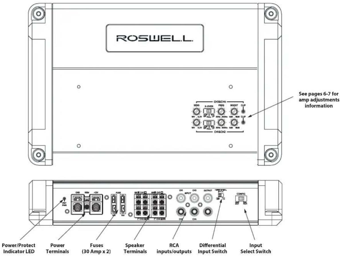
ROSWELL. See pages 6-7 for amp adjustments information Power/Protect Indicator LED Power Terminals Fuses (30 Amp x 2) Speaker Terminals RCA inputs/outputs Differential Input Switch Input Select Switch900.6
text_image
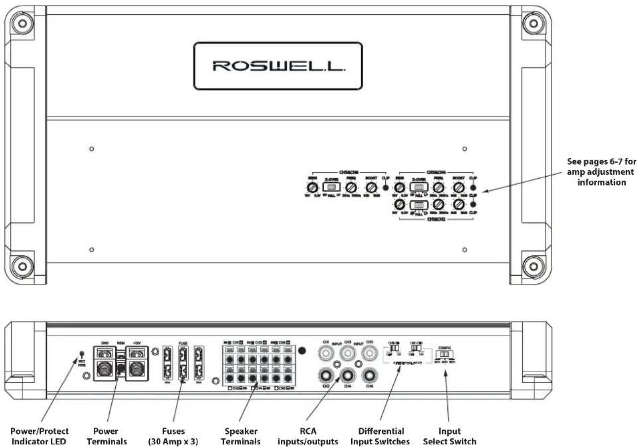
ROSWELL. See pages 6-7 for amp adjustment information Power/Protect Indicator LED Power Terminals Fuses (30 Amp x 3) Speaker Terminals RCA inputs/outputs Differential Input Switches Input Select SwitchPACKAGE CONTENTS
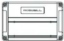
(x1)
Amplifier
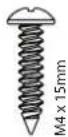
(x4)
Mounting Screws
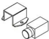
Remote Gain Module
(1000.1 Only)
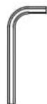
2mm Allen Key
3mm Allen Key
4mm Allen Key
TOOLS & SUPPLIES NEEDED
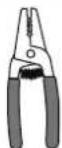

Wire Strippers Phillips Screw Small Flathead Electrical
Screw Driver
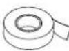
Tape
& Crimps
Driver
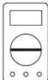
Multimeter
(Optional)

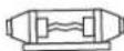
4AWG Wire Inline Fuse
Notes
Warning
If you do not have experience with automotive or marine electrical and mechanical systems please contact a professional installer. Paying a qualified installer is almost always cheaper than paying a dealership to repair your boat.
Please check the suitability of the installation location before you begin. Do not cut any of the boat's structure. Pay close attention to what is behind any bulkheads, panels and carpet. Often the boat manufacturer will hide wires and cables in the exact location you may wish to install in.
Location of the Amplifier
The amplifier must be securely mounted to a solid surface. Please select a dry location such as in the storage compartment. Do not mount the amplifier to any area that may have excessive vibration (like the subwoofer box), under any cup holder drain lines, or under ballast drain/vent fittings that may leak water. Position the amplifier in an area that receives sufficient airflow and mount it vertically or completely flat for optimal heat dissipation.
Supplying Enough Power
The R1 Series amplifiers are capable of significant output. In order to achieve this it is critical that the amplifiers 12 Volt wiring is adequate to provide the necessary power to the amplifier. We recommend using 4AWG wire for all power and ground connections. Be sure to fuse the power wire appropriately for the amount of current being drawn.
The Ground
The ground wire should be connected directly to the battery of your boat. Remember, the ground must carry the same high current as the positive wire.
RCA Cables
The R1 Series amplifiers feature differential RCA inputs for maximum noise rejection. However, it is still a good idea to follow best practices to minimize the amount of interference in the signal chain. To reduce the risk of noise, run all signal cables away from any power supplying wires.
Protection Indicator
This amplifier is equipped with an advanced protection system. If for any reason this unit goes into protection mode it will flash a solid single red LED light found on the control end of the amplifier. In most cases, the amp will automatically recover once the issue causing the protect mode is corrected.
Installing Multiple Amplifiers
Roswell offers a stacking spacer for use with R1 Amps (C920-1830). These allow you to stack amplifiers on top of each other securely. Roswell recommends stacking a maximum of four amplifiers when done on a flat surface or two amplifiers when mounted on a vertical surface. It may be necessary to provide more airflow for more amplifiers as more amps will generate more heat.
Sensitivity
Due to the wide range of head unit output configurations all RMA amplifiers have an adjustable input sensitivity. The level is not a volume control. It is used to properly set the output of the amplifier based on the output voltage of the source unit, and to ensure the speakers are receiving clean power at an appropriate level. With the sensitivity turned up, the amplifier will reach maximum output at a lower volume setting on the source unit.
There is no correct sensitivity setting suitable for all applications as head unit preamp outputs vary. If you are unsure on adjusting this settings, consult an audio installation professional.
Crossover Controls
A crossover is a circuit that filters unwanted frequencies. A tweeter can easily be blown by bass frequencies if they are not filtered out. A subwoofer will not sound natural if it is playing mid range frequencies. Careful adjustment is needed to ensure that all speakers are playing the right frequencies and that they are left with no gaps in the frequency response.
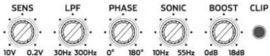
The R1 Series amplifiers feature calibrated potentiometers in the crossover section which allows for very precise adjustment of the filter frequency. The 900.6 and 650.4 amplifiers feature a single crossover. Simply select whether you would like the crossover to be a low-pass or high-pass, and adjust accordingly. The 1000.1 also features a Subsonic (infrasonic) filter, which is explained in detail below.
Full - Allows the full range of frequencies to pass through.
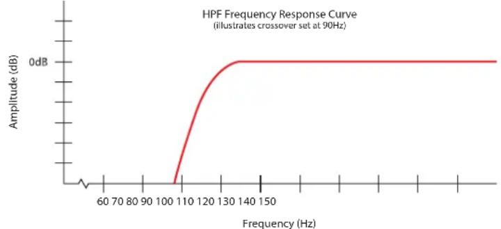
HPF (High-Pass Filter) - A high-pass filter allows high frequency signals to pass through while reducing all signals lower than the cutoff frequency setting on its dial.
line
| Frequency (Hz) | Amplitude (dB) | | -------------- | -------------- | | 60 | ~0 | | 70 | ~0 | | 80 | ~0 | | 90 | ~0 | | 100 | ~0 | | 110 | ~-5 | | 120 | ~-2 | | 130 | ~0 | | 140 | ~0 | | 150 | ~0 |LPF (Low-Pass Filter) - A low-pass filter allows low frequency signals to pass through while reducing all signals higher than the cutoff frequency setting on its dial.
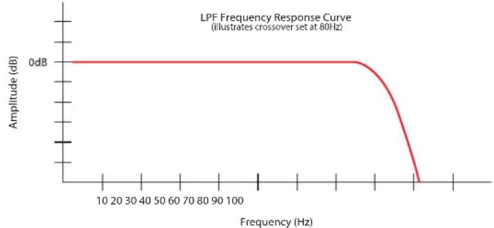
line
| Frequency (Hz) | Amplitude (dB) | | -------------- | -------------- | | 10 | 0 | | 20 | 0 | | 30 | 0 | | 40 | 0 | | 50 | 0 | | 60 | 0 | | 70 | 0 | | 80 | 0 | | 90 | 0 | | 100 | 0 | | >100 | <0 |Subsonic (1000.1 & 550.2 only) - A Subsonic, or infrasonic, filter is essentially a high-pass filter dedicated to removing the lowest frequencies. This allows you to remove unwanted frequencies in order to protect your subwoofer from excess power, or to prevent it from unloading when it is in a ported enclosure or free-aired application. In most cases this filter should be set at around 30 Hz (12:00 position on the dial).
Phase Control (1000.1 & 550.2 only) - The Phase control allows you to fine-tune the output of the amplifier in order to ensure that the sound from the subwoofer is in-phase with the sound with the rest of the audio system maximize the bass output. Depending on your subwoofer mounting location this may not need to be adjusted. If you are unsure on how to properly adjust this setting, leave it alone.
Bass Boost
All of the RMA amplifiers have an adjustable bass boost from 0-18 dB @ 45 Hz. Adjust the Bass Boost carefully - the response on the power output is tremendous!
Remote Gain Control
The 1000.1 Amplifier includes a remote gain control module that can be plugged into the amplifier to allow easy reduction of the gain setting without accessing the amplifier.
RCA Inputs
All R1 amplifiers feature switchable differential RCA inputs to maximize noise rejection.
Input Select Switch
The 900.6 and 650.4 amplifiers feature an input selection switch that will allow you to set which RCA inputs feed signal to the amplifier. You can choose a dedicated RCA input for each channel, or to have one pair of RCAs to supply the signal to all channels. The 900.6 also allows for 4 channel input to control all 6 outputs. This allows you to group channels together to easily interface with head units that feature zone control, or to use with our Dual Zone Volume Control.
NOTE: Set this switch before tuning your amplifier.
RCA Line Out
The 1000.1, 550.2, and 650.4 amplifiers have line out connections that allow you to connect multiple amplifiers together. The 550.2 and 650.4 line outs supply a full range stereo signal. The 1000.1 line out supplies a mono signal as it is designed to provide signal to additional subwoofer amplifiers.
Speaker Outputs
All R1 amplifiers are equipped with a block style terminal for speaker connection. Make these connections carefully and neatly. Strip your wire back 5/8" (16mm) and twist the exposed leads. Using a 2mm Allen wrench, loosen the terminal set screws far enough to allow the wire to fit. Insert them into the appropriate spot on the block terminal. Make sure that there are no loose or frayed strands of wire sticking out. If a wire comes in contact with another wire, the amplifier will go into protection mode. After tightening the terminal set screws, verify your wires are secured in place by gently pulling on them.
Impedance
The 900.6 and 650.4 Amplifiers are 2Ω stable on each channel, meaning that up to two 4Ω speakers can be wired in parallel per channel. When bridging channels the speaker must have a nominal impedance of at least 4Ω. Attempting to run speakers below 4Ω when bridging channels could result in damage to the amplifier and will void the warranty.
The 1000.1 Amplifier is 1 stable, meaning that up to four 4 subwoofers can be connected to the amplifier simultaneously.
If you are unsure about impedance matching or series vs. parallel wiring, consult an audio installation professional.
Technical Specifications
| Parameter 1000.1 | 550.2 | 650.4 | 900.6 | |
| Continuous power: | ||||
| @ 4 | 400W 165W x2 | 100W x4 | 100W x6 | |
| @ 2 | 675W 275W x2 | 165W x4 | 165W x6 | |
| @ 1 | 1000W N/A | N/A | N/A | |
| Bridged power | N/A | 4Ω: 550W x1 | 4Ω: 300W x2 | 4Ω: 300W x3 |
| Frequency Response (+/- 1dB) | 10Hz-400Hz | 10Hz-25 kHz | 10Hz-25 kHz | 10Hz-25 kHz |
| Input Sensitivity | 0.2-10.0V | 0.2-10.0V | 0.2-10.0V | 0.2-10.0V |
| Crossover Frequency Range | 30Hz-300Hz | 30Hz-300Hz | 30Hz-300Hz | 30Hz-300Hz |
| Subsonic Filter | 10Hz-55Hz | 10Hz-55Hz | Auto 6dB/oct.@ 30Hz in HPF Mode | Auto 6dB/oct.@ 30Hz in HPF Mode |
| Phase Control | 0-180° Continuous | 0-180° Continuous | N/A | N/A |
| 0-18dB @ 45Hz 0-18dB @ 45HzBass EQ | 0-18dB @ 45Hz | 0-18dB @ 45Hz | ||
1000.1
Amplifier Application Examples
Single Sub Output
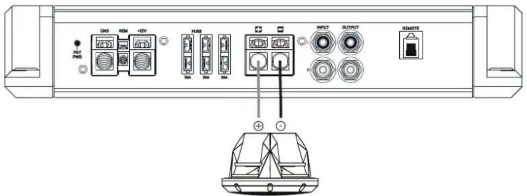
text_image
GND REM +DV PET PMR PUSE 30A 30A 30A INPUT OUTPUT REMOTE + -Subwoofer 1-8Ω
Double Sub Output
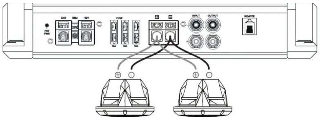
text_image
GND ROM +DV POT PWM FA FA FA INPUT OUTPUT REMOTE + -Subwoofer 2-8Ω Subwoofer 2-8Ω
Quadruple Sub Output
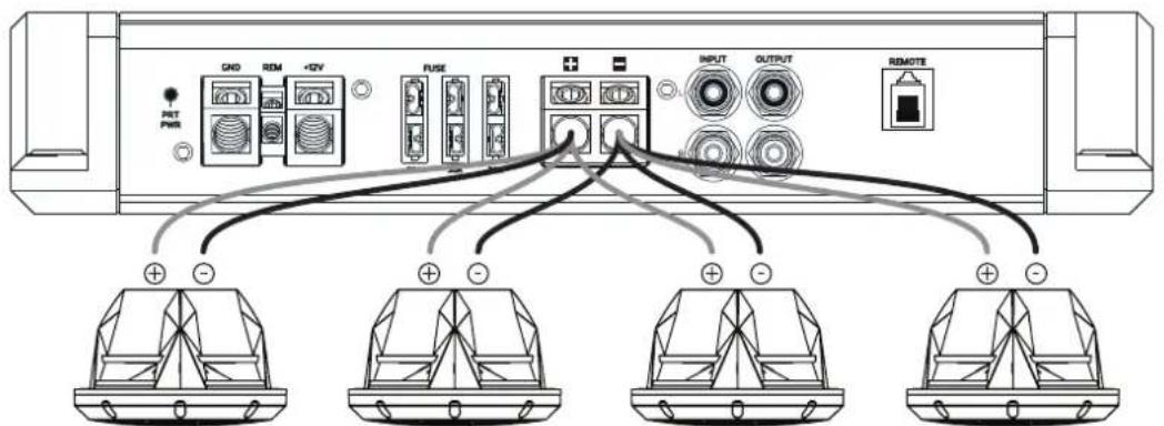
text_image
GND REM +DV POT PWM FUSE INPUT OUTPUT REMOTE + - + + - + + - + + - +Subwoofer 4-8Ω Subwoofer 4-8Ω Subwoofer 4-8Ω Subwoofer 4-8Ω
Control Panel
Note: Settings shown are for illustrative purposes only and are NOT standard or recommended settings
text_image
SENS 10V 0.2V LPF 30Hz 300Hz PHASE 0° 180° SONIC 10Hz 55Hz BOOST 0dB 18dB CLIP650.4
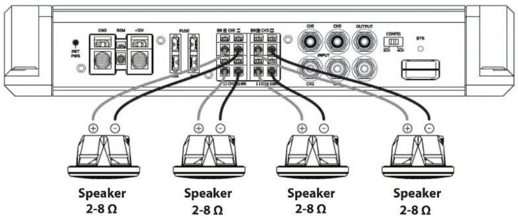
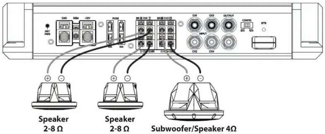
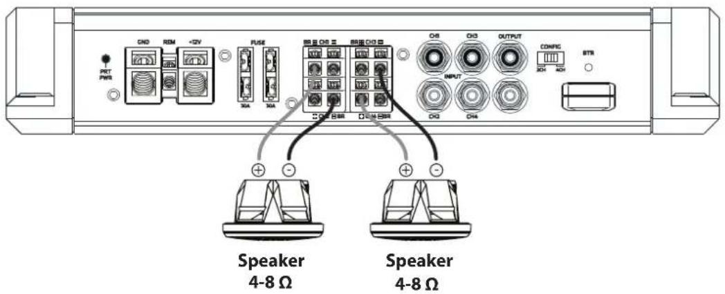
Amplifier Application Examples
4- Channel Output
text_image
PRT PWM CND REM +DV PULSE BRIP OR = BRIP OR = CND O1 O2 OUTPUT CONFIG STRI INPUT Speaker 2-8 Ω Speaker 2-8 Ω Speaker 2-8 Ω Speaker 2-8 Ω3- Channel Output
text_image
PMT PWM CN0 RDN +2V FUSE 30A 30A BR1 CN1 BR2 CN2 30C LBM 31C MAM CN3 CN4 OUTPUT CONFIG INPUT BTR Speaker 2-8 Ω Speaker 2-8 Ω Subwoofer/Speaker 4Ω2- Channel Output
text_image
PCT PWM ON0 REM +2V FUSE 30A 30A OFF ON1 ON2 ON3 ON4 OUTPUT CONFIG 30H 40H STR ON5 ON6 ON7 ON8 ON9 ON10 Speaker 4-8 Ω Speaker 4-8 ΩControl Panel
Note: Settings shown are for illustrative purposes only and are NOT standard or recommended settings
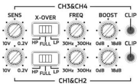
text_image
CH3&CH4 SENS X-OVER FREQ BOOST CLIP 10V 0.2V HP FULL LP 30Hz 300Hz 0dB 18dB CLIP 10V 0.2V HP FULL LP 30Hz 300Hz 0dB 18dB CH1&CH2900.6
Amplifier Application Examples
6- Channel Output
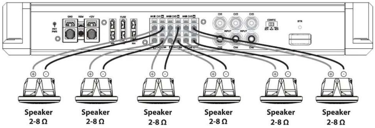
text_image
GND REM +2V FUSE CH3 CH5 CH6 CH7 CH8 CH9 CH10 CH11 CH12 CH13 CH14 CH15 PNT PWS COMP C INPUT INPUT BTR Speaker 2-8 Ω Speaker 2-8 Ω Speaker 2-8 Ω Speaker 2-8 Ω Speaker 2-8 Ω + - + Speaker 2-8 Ω Speaker 2-8 Ω Speaker 2-8 Ω Speaker 2-8 Ω5- Channel Output
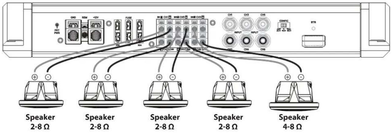
text_image
GND REM +2V FUSE INT PWR CH3 CH4 CH5 CH6 INPUT INPUT COMPIC BTR Speaker 2-8 Ω Speaker 2-8 Ω Speaker 2-8 Ω Speaker 2-8 Ω Speaker 4-8 Ω4- Channel Output
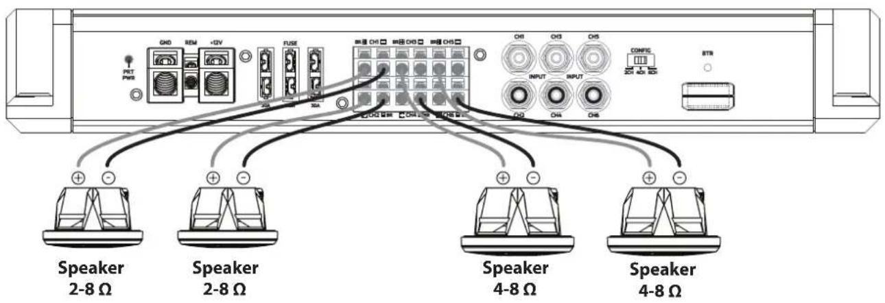
text_image
GND REM +GV FUSE CH3 CH1 CH2 CH3 CH4 CH5 CH3 CH1 CH2 CH3 CH4 COMP INPUT INPUT C/O CH4 CH5 BTR Speaker 2-8 Ω Speaker 2-8 Ω Speaker 4-8 Ω Speaker 4-8 Ω900.6 continued
Amplifier Application Examples
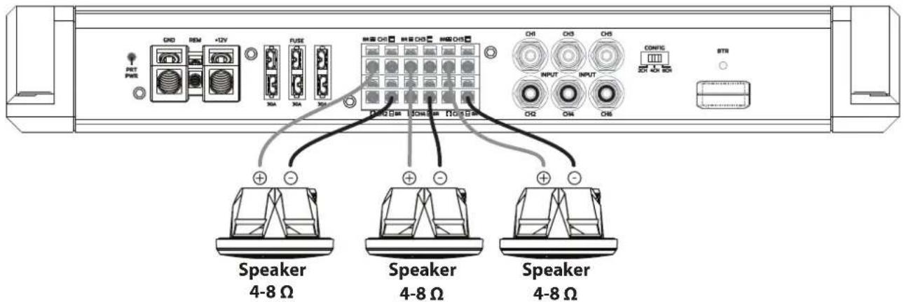
6- Channel Output
text_image
PNT PWE CKD REM +2V X0A X0A X0B FUSE CKD CKD KND CKD CKD CKD CKD CKD CKD CKD CKD CKD CKD CKD CKD CKD CKD CKD CKD CKD CKD CKD CKD CKD CKD CKD CKD CKD CKD CKD CKD CKD CKD CKD CKD CKD CKD CKD CKD CKD CKD CKD CKD CKD CKD CKD CKD CKD CKC CKD CKD CKC CKD CKD CKC CKD CKD CKC CKD CKD CKC CKD CKD CKC CKD CKD CKC CKD CKD CKC CKD CKD CKC CKD CKD CKC CKD CKD CKC CKD CKD CKC CKD CKD CKC CKD CKD CKC CKD CKD CKC STB Speaker 4-8 Ω Speaker 4-8 Ω Speaker 4-8 ΩControl Panel
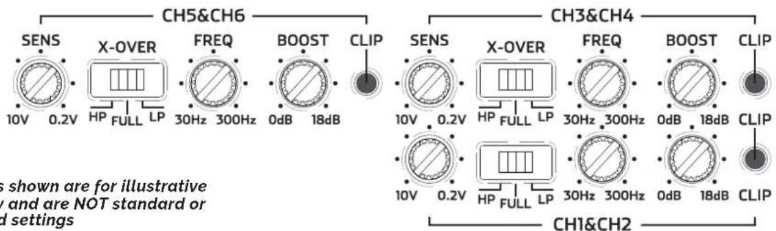
text_image
CH5&CH6 SENS 10V 0.2V X-OVER FREQ BOOST CLIP HP FULL LP 30Hz 300Hz 0dB 18dB CH3&CH4 SENS 10V 0.2V X-OVER FREQ BOOST CLIP HP FULL LP 30Hz 300Hz 0dB 18dB CLIP HP FULL LP 30Hz 300Hz 0dB 18dB CLIP CH1&CH2 s shown are for illustrative y and are NOT standard or d settingsNote: Settings shown are for illustrative purposes only and are NOT standard or recommended settings
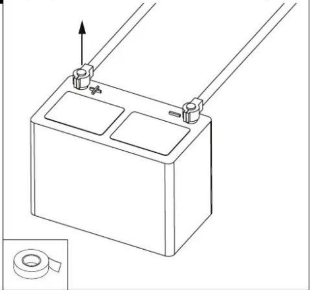
A
Disconnect the positive cable from the boat battery. Tape up the end so it is isolated from the battery.
natural_image
Technical line drawing of a battery with two compartments and two terminals, showing an upward arrow and a magnified inset of the bottom-right corner (no text or symbols)B
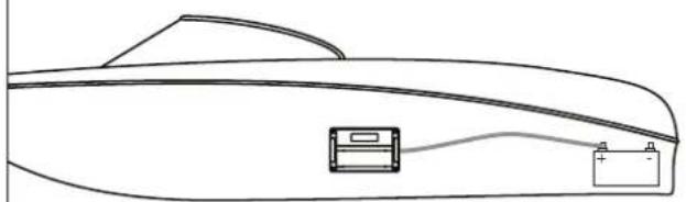
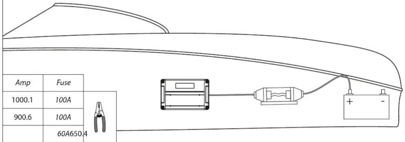
Run a 4 AWG wire from the battery to the amplifier. Plan this part of the installation carefully.
This cable will carry a very high current. If it should short to any metal and is not properly fused it could catch fire.
natural_image
Line drawing of a car rear bumper with battery and charging cable (no text or symbols)C
To protect the power wires, connect an in-line fuse holder to the power cable as close to the battery as possible. If one amplifier is being used, refer to the table below for recommended fuse rating. If two or more amplifiers are being used, verify the fuse and wire are capable of handling the total current load of all amplifiers connected. The amplifiers themselves are internally fused and do not require additional protection.
text_image
Amp Fuse 1000.1 100A 900.6 100A 60A650.4D
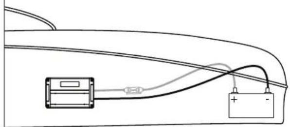
Run the black 4 AWG ground wire directly to the negative (-12V) pole on the battery. This wire should handle the load in the previous step and be as short as possible.
natural_image
Simple line drawing of a car interior with battery and switch (no text or symbols)E
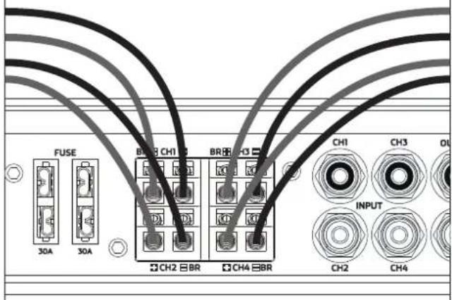
Wire your speakers and route wires to your amp mounting location. Using the allen key, connect the speaker wires to the amplifier. Be sure to note the wire polarity.
text_image
FUSE 30A 30A BR CH1 CH2 BR BR CH3 CH4 BR CH1 CH3 OL INPUT CH2 CH4
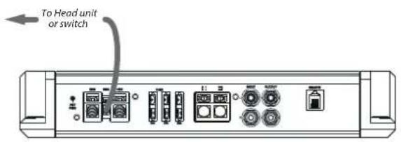
Run a wire from the head unit remote turn-on wire (typically blue or blue w/ white stripe) to the "REM" terminal of the amplifier.
text_image
To Head unit or switch
Turn on the amplifier to verify it is wired correctly and does not go into protection mode. The power LED should turn solid blue after a few seconds.
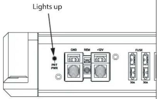
text_image
Lights up PRT PWR GND REM +12V FUSE 30A 30AYou must now set the controls on the amplifier.
This is the most important part of amplifier installation and should be completed by a trained audio professional.

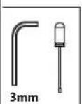
Remove control panel cover with a 3mm allen wrench. Adjust amplifier settings to provide appropriate power to the speakers. Replace cover when complete.
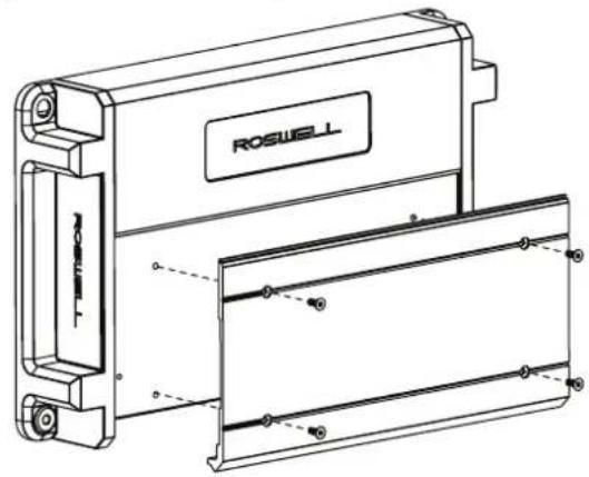
natural_image
Technical line drawing of a Roswell industrial device with mounting bracket and internal panel (no text or symbols)Roswell Limited Warranty
Roswell warrants all new R1 Series Amplifiers against defects in material and workmanship for a period of TWO (2) YEARS from the original date of purchase. This warranty is not transferable and applies only to the original retail purchaser from an authorized Roswell retailer. Upon inspection by Roswell, should service be necessary under this warranty for any reason due to manufacturer defects, Roswell will, at our own discretion, repair or replace the defective product with new or similar conditioned product at no charge.
THIS WARRANTY DOES NOT COVER INSTALLATION OR DAMAGE RESULTING FROM ACCIDENT, MISUSE, ABUSE, IMPROPER WIRING, COSMETIC DAMAGE DUE TO NORMAL WEAR AND TEAR, EXPOSURE TO CHEMICALS OR HARSH ENVIRONMENTS, OPERATION OUTSIDE OF THE MANUFACTURERS RECOMMENDATIONS OR SPECIFICATIONS, OR AGAINST INSTRUCTIONS IN OWNERS MANUAL. IN ADDITION, ANY PRODUCT THAT HAS BEEN OPENED, TAMPERED WITH OR MODIFIED, OR IF ANY SERIAL NUMBERS HAVE BEEN REMOVED, WILL NOT BE COVERED BY ANY PART OF THE MANUFACTURES WARRANTY.
All warranty claims must first be made in direct contact with Roswell's warranty department. When first contact is made the warranty representative will issue an RA # to open a claim. All warranty returns should be sent to Roswell freight prepaid and must be accompanied by proof of purchase (a copy of original sales receipt). Direct returns from consumers or non-authorized retailers will be refused unless specifically authorized by Roswell with a valid return authorization number (RA#).
All warranty returns should be packed in the original packaging and must be accompanied by a copy of the original sales receipt. Product damage during shipping will not be covered under this warranty. The customer or retailer may choose to have this damage repaired at the normal "Out of Warranty" repair cost.
In no event will Roswell be liable for incidental, consequential, or other damages resulting from the use of this product. This includes but is not limited to, damage of hearing, property or person, damage based upon inconvenience or on loss of use of the product, and to the extent permitted by law, damages for personal injury.
This warranty applies to products being sold and used in the United States of America and Canada. In all other countries please contact your authorized Roswell representative.
For warranty and non-warranty repairs, please contact Roswell Marine Inc.
Phone: 1-321-638-1331
Email: warranty@roswellmarine.com
Cooling & Airflow Warning
AMPLIFIER MAY BECOME VERY HOT DURING NORMAL OPERATION
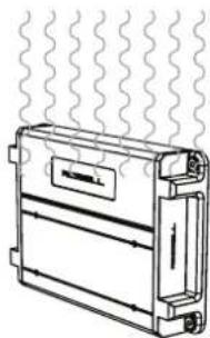
Your new Roswell Marine Audio amplifier possesses exceptional efficiency and thermal management. However, it is possible that, if mounted in a confined space and/or high temperature environment, it may become extremely hot during periods of extended use.
Special attention must be given during the installation process to optimize cooling efficiency. An unobstructed airflow around the amplifier's heat sink is required to enable proper cooling.
For optimal performance Roswell recommends mounting the amplifier as follows:
natural_image
Diagram of a heat exchanger or cooling unit with wavy lines indicating airflow or heat transfer (no text or symbols)Vertical Mount
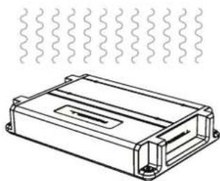
natural_image
Technical line drawing of a rectangular electronic component with wavy internal lines and mounting holes (no text or symbols)Flat Mount
Mounting the amplifier in a position that does not enable proper cooling will affect the performance of the unit and is strongly discouraged.
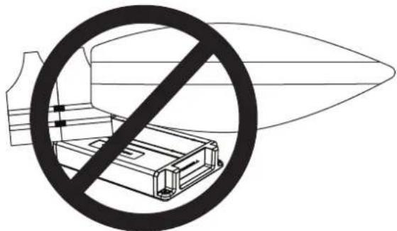
In addition to proper mounting ensure that no items are in direct contact with the amplifier Life vests, wet suits, towels, coolers, and other like items must be kept away from amplifier.
natural_image
Symbolic illustration of a missile with a prohibition sign crossed out by a circular arrow, containing no text or symbols.Roswell Marine is not liable for damage resulting from improper mounting and/or negligent use of this product.