
VCC-HD2100P - Security Camera SANYO - Free user manual and instructions
Find the device manual for free VCC-HD2100P SANYO in PDF.


| Product Type | Security Camera |
| Brand | Sanyo |
| Model | VCC-HD2100P |
| Image Sensor | 1/3-inch CMOS |
| Resolution | 1920 x 1080 (Full HD) |
| Frame Rate | 30 fps at 1080p |
| Lens Type | Fixed focal length, 3.6mm |
| Minimum Illumination | 0.01 lux (color), 0 lux with IR |
| Infrared Range | Up to 20 meters |
| Video Output | BNC (analog HD), CVBS |
| Power Supply | DC 12V ±10% |
| Power Consumption | Max 5W (IR on) |
| Dimensions (W x H x D) | 70mm x 60mm x 130mm |
| Weight | 350g |
| Mounting Type | Wall or ceiling mount |
| Weatherproof Rating | IP66 (indoor/outdoor) |
| Operating Temperature | -10°C to 50°C |
| Storage Temperature | -20°C to 60°C |
| Main Functions | Motion detection, privacy masking, day/night mode |
| Cleaning and Maintenance | Clean lens with soft cloth; avoid solvents |
| Safety | Use only specified power adapter; avoid water ingress |
| Spare Parts and Repairability | Contact authorized service center for parts |
| General Information | Analog HD security camera; compatible with DVR |
Frequently Asked Questions - VCC-HD2100P SANYO
User questions about VCC-HD2100P SANYO
0 question about this device. Answer the ones you know or ask your own.
Ask a new question about this device
Download the instructions for your Security Camera in PDF format for free! Find your manual VCC-HD2100P - SANYO and take your electronic device back in hand. On this page are published all the documents necessary for the use of your device. VCC-HD2100P by SANYO.
USER MANUAL VCC-HD2100P SANYO
Features of This Camera
Specifications
Name and Function of Each Component
Connections
Lens Installation
Lens Adjustment
Viewing Firmware Version
Features of This Camera
Support of Network Operation
The camera supports network operation. By simply connecting a LAN cable to it, you can construct the most advanced network monitoring system. From the Web browser (Internet Explorer) installed on your PC, you can operate the camera via the network in an easy-to-use manner.
In addition, it is a PoE product that can be powered through a LAN cable, so you can install it in locations where there is no power outlet nearby.
High-Resolution and High-Quality Images
The camera has 4-megapixel CMOS sensor that produces clear images at ultra-high resolution.
The camera can deliver full HD H.264 video throughout the network. Connecting a high-definition monitor to your PC enables full high-definition video monitoring.
The camera supports both H.264 video and JPEG image compression formats, which you can choose from depending on the network environment.
A Variety of Functions in One Compact Body
The camera offers the focus assist function that supports focus adjustment at megapixel image resolution, allowing you to fine-tune the focus in optimal conditions in an easy manner.
The camera's motion sensor function can work in conjunction with any external alarm device, facilitating the construction of a high-level security system.
Highly Scalable Design
Installing associated software applications on your PC further extends the capabilities of your surveillance system.
Specifications
Camera
| Image pickup device 1/3" CMOS sensor | |
| Effective pixels 16:9 1920 (H) × 1080 (V), 4:3 2288 (H) × 1712 (V) | |
| Lowest image illumination | 50IRE: 1.0 lx (at F1.2, color mode, high gain)50IRE: 0.06 lx (at F1.2, black-and-white mode, high gain) |
| Video S/N ratio | 50dB (when AGC is "OFF") |
| Lens mount CS mount | |
| Flange back adjustment | 12.5±0.5 mm, electrical flange back adjustment (Focus assist function) |
| Day/Night function Auto, color, black-and-white, alarm input switching( (VCC-HD2300P/VCC-HD2300 only)) | |
| White balance | Auto (ATW), one push (AWC), manual (R/B gain adjustable), indoor, outdoor, fluorescent |
| Backlight compensation | Multi-spot evaluative metering, center-weighted average metering, masking |
| Electronic sensitivity boosting | Auto (32× max) or Off |
| Electronic shutter | VCC-HD2300P/VCC-HD2100P: 1/25, 1/50, 1/120, 1/250, 1/500, 1/1000, 1/2000, 1/4000, 1/10000VCC-HD2300/VCC-2100: 1/30, 1/60, 1/100, 1/250, 1/500, 1/1000, 1/2000, 1/4000, 1/10000Long exposure shutter (1×, 2×, 4×, 8×, 16×, 32×) |
| Electronic iris ON/OFF (Set [SHUTTER] to "EI".) | |
| Iris control | DC iris lens supported |
| Camera settings Selectable between 2 camera setting patterns | |
| AGC gain Normal/Middle/High (Manual gain setting possible at Off) | |
| Gamma correction 0.45, 1, Mode 1, Mode 2 | |
| Aperture compensation On/Off (Correction level adjustable) | |
| VIVID COLOR EFFECT | ON/OFF |
| DNR ON/OFF | |
| Mirror H/V/HV/OFF | |
| Privacy mask | On/Off, max. 8 mask patterns |
| Motion sensor | On (masking/detection area setting)/Off |
| Language selection | English, French, German, Spanish, Japanese |
110
| Video output | Composite output |
| LAN | 10BASE-T/100BASE-TX (RJ-45 connector) |
| Alarm input | 2 (NO/NC), also serve as Day/Night switching signal (VCC-HD2300P/VCC-HD2300 only) |
| Alarm output | 2 (NO/NC, 16V, 150 mA, open collector) |
Network
| Image/video compression | H.264/JPEG |
| Video size (H.264) | (16:9) 1920×1080, 1280×720, 640×360, 320×180(4:3) 1600×1200, 1280×960, 1024×768, 640×480, 320×240 |
| Video size (JPEG) | (16:9)1920×1080, 1280×720, 1024×576, 640×360(4:3) 2288×1712, 1600×1200, 1280×960, 1024×768, 800×600, 640×480, 320×240 |
| Picture quality | QUALITY mode: BASIC, NORMAL, ENHANCED, FINE, SUPER FINEBITRATE mode: User-specified bit rate |
| Interface 10BASE-T/100BASE-TX | |
| Protocol TCP/IP, UDP, HTTP, HTTPS, SMTP, NTP, DHCP, FTP, DDNS, RTP, RTSP, RTCP | |
| Simultaneous access 20 | |
| Security | BASIC authentication (ID/password), SSL, IP filtering |
Others
| Operating ambient temperature/humidity | -10 to +50°C, 90% RH or less (no condensation) |
| Power source | 12 to 15 VDC/24 VAC±10%, 50/60 Hz, PoE |
| Power consumption | 4,6 W |
| Weight | 220 g |
Dimensions
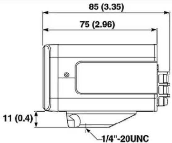
text_image
85 (3.35) 75 (2.96) 11 (0.4) 1/4"-20UNC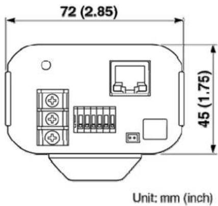
text_image
72 (2.85) 45 (1.75) Unit: mm (inch)Accessories
1Video cable
2 Cable holder for wiring
3CD-ROM
Name and Function of Each Component
Rear Face
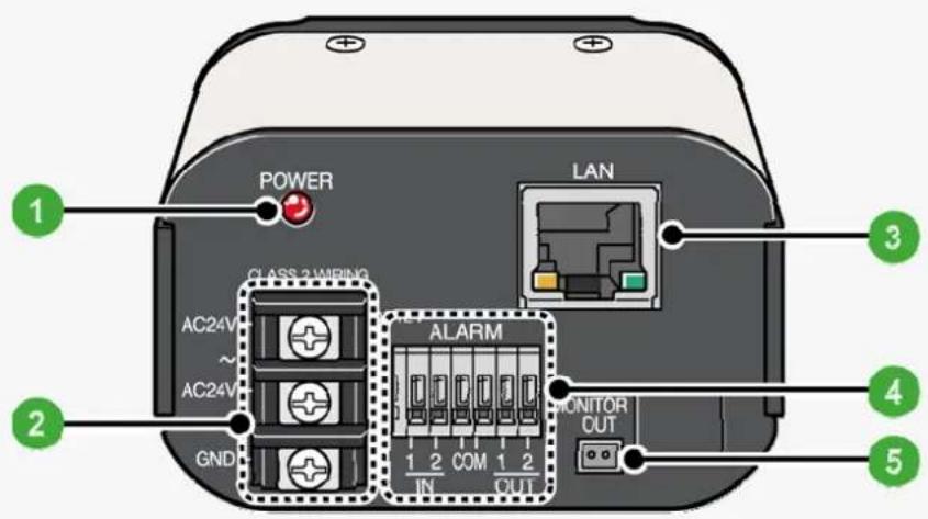
text_image
POWER CLASS 2 WIRING AC24V ~ AC24V GND ALARM 1 2 COM 1 2 IN OUT LAN MONITOR OUT 1 2 3 4 51 Power Indicator (POWER)
This indicator lights up when the camera is powered on.

The indicator blinks while the firmware is being updated.
2 24 VAC/12 VDC Power Terminals
Use these terminals to connect a 24 VAC or 12 VDC power supply. The power indicator lights up when the camera is powered on.
For details, refer to the "Basic Connections" section.
3 Network Socket (LAN, RJ-45)
Use this socket to connect the camera to your PC to enable network operation.
For details, refer to the "Basic Connections" section.

Right: Link access indicator (Green)
This indicator lights up approx. 3 seconds after power on, if a connection has been established between the camera and the network.
After that, it will blink when data are being transmitted via the network.
Left: Speed indicator (Orange)
The camera automatically detects the local network transmission speed (10BASE-T or 100BASE-TX).
This indicator lights up when 100BASE-TX data transmission is in progress; it goes out when 10BASE-T data transmission is in progress.
4 Control Terminals (6 push-lock pins)
For the detailed connection procedure, refer to the "Alarm Input/Output Terminal Connections" section.
1 Alarm input or Day/Night switching terminals (ALARM IN1/2)
These input terminals can be used for either of the following purposes:
Alarm input
Connecting an external switch, infrared sensor, or other device to these terminals enables the camera to detect alarm conditions such as the entry of an intruder.
Day/Night switching
Normally, switching the camera between the color and black-and-white video modes is automatically accomplished by the Day/Night function.
When used as Day/Night switching terminal, you can switch between color and black-and-white video modes using an external control signal.
(This function is supported only by VCC-HD2300P/VCC-HD2300)

Using network operation, under [DAY/NIGHT], set [DAY/NIGHT] to "COLOR" and select the terminal you want to use in [EXT ALARM].
Then, in [POLARITY] under [ALARM SETTINGS], select the signal polarity of the alarm input terminal.
2Alarm output terminals (ALARM OUT1/2)
Connect a buzzer, lamp, or other alarm device to these terminals.
3COM terminal (Earth grounding terminal)
5 Monitor Output Socket (MONITOR OUT)
Connect the camera to your monitor via the supplied video cable.
You can perform focus and iris adjustments while monitoring live video on the monitor.
For details, refer to the "Basic Connections" section.
Side Face
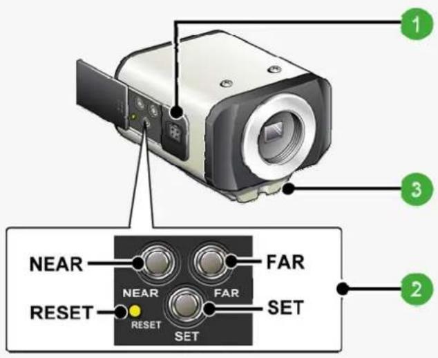
text_image
1 3 NEAR FAR NEAR FAR 2 RESET RESET SET SET1 Auto Iris Lens Socket
Use this socket to connect an optional auto iris lens.
For details, refer to the "Lens Installation" section.
2 Operation Buttons
Use the buttons provided on the left-side face of the camera to perform the following operations.
These operations may be performed with the Web browser installed on your PC. For details, refer to the linked information.
| Operation Associated | button and use Equivalent network operation | screen |
| Restarting camera Press the R | RESET button. OPTION SETTINGS (CAMERA REBOOT) | |
| Restoring factory default settings | Press the NEAR and SET buttons simultaneously. | OPTION SETTINGS (FACTORY DEFAULT) |
| Restoring factory default back focus position | Press the NEAR and FAR buttons simultaneously. | CAMERA SETTINGS (FOCUS ASSIST) |
| Resetting login password Press the FAR and SET buttons simultaneously. | USER SETTINGS | |
| Adjusting focus For details, refer to the “Lens Adjustment” section. | CAMERA SETTINGS (FOCUS ASSIST/IRIS SETTINGS) | |
| Adjusting iris | ||
| Viewing Firmware Version For details, refer to the “Viewing Firmware Version” section. | OPTION SETTINGS (FIRMWARE UPDATE) | |

Bracket
This bracket may be attached to either the top or bottom face of the camera depending on the installation environment.
For bracket installation, be sure to use the longer screws supplied.
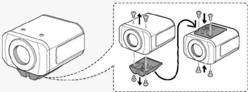
natural_image
Technical illustration of a mechanical assembly with two views showing internal components and mounting holes (no text or symbols)
Install the camera securely to a durable location, taking into account the total weight of the camera mount (commercially available) and the camera.
Connections
Perform the following connections according to the installation environment and application of your camera.
Basic Connections
Alarm Input/Output Terminal Connections

Before attempting the following connections, be sure to turn off all components of your system. Improper connection may cause smoke or failures. Before attempting to connect each system component, carefully read the instruction manual that comes with it to familiarize yourself with the correct connection procedure.
Basic Connections
flowchart
graph TD
    A["24 VAC"] -->|24 VAC| B["AC24V AC34V GND"]
    C["12 VDC"] -->|12 VDC| D["AC24V AC34V GND"]
    E["Power supply"] --> F["POWER"]
    F --> G["12V ALARM"]
    G --> H["MONITOR OUT"]
    H --> I["PC (optional)"]
    H --> J["Monitor (optional)"]
    H --> K["Coaxial cable"]
    L["PC (optional)"] --> M["Computer"]
    N["Monitor (optional)"] --> O["Computer"]
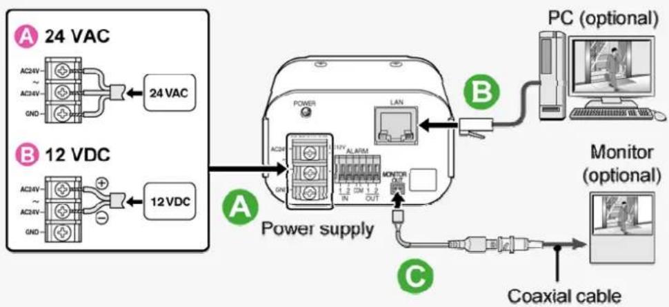
A Power Connection
Connect the power terminals (24 VAC/12 VDC) of the camera to a power supply.
A Connection to 24 VAC power supply
Although the power terminals have no polarity, the earth grounding wire must be connected to the GND (earth grounding) terminal.
BConnection to 12 VDC power supply
Note the polarity (+/-) of the power terminals when connecting the camera to a 12 VDC power supply. Incorrect polarity may cause damage to the camera.

Be sure to use an 18AWG or thicker wire power cable.
A voltage drop may occur depending on the thickness of the power cable. If you must use a long power cable, determine the cable type by ensuring that the voltage at the 24-VAC/12-VDC terminals is within the operating range of the camera.
When using PoE to power the camera, do not use the camera's power terminals.
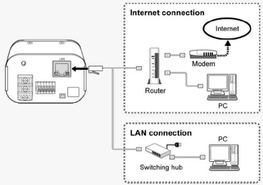
B Network Connection
This camera is designed so that you can use all of its functions via network operation. By connecting the network (LAN) socket of the camera to your PC using a LAN cable, you can configure and operate it from the Web browser installed on your PC.
flowchart
graph TD
    A["Internet connection"] --> B["Router"]
    B --> C["Modem"]
    C --> D["PC"]
    B --> E["Switching hub"]
    E --> F["PC"]
    style A fill:#f9f,stroke:#333
    style B fill:#ccf,stroke:#333
    style C fill:#cfc,stroke:#333
    style D fill:#fcc,stroke:#333
    style E fill:#cff,stroke:#333
    style F fill:#ffc,stroke:#333

Use a LAN cable no longer than 100 m (109.4 yards) with the shield type CAT5 or higher.
The supported Web browser is Internet Explorer Ver.6.0 SP2 or higher, or Internet Explorer Ver.7.0.
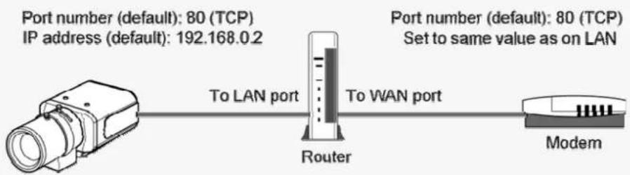
About the internet connection
Port forwarding for the video port must be enabled on the broadband router.
For details on how to set port forwarding, please refer to your router's Instruction manual.
flowchart
graph LR
    A["Port number (default): 80 (TCP)<br>IP address (default): 192.168.0.2"] --> B["To LAN port"]
    B --> C["Router"]
    C --> D["To WAN port"]
    D --> E["Modem"]

To connect two or more cameras, on the NETWORK SETTINGS screen, assign them with port numbers that are different from that of the first camera.
Using PoE
This camera supports PoE (Power over Ethernet). This means that you can install the camera in locations where there is no 24-VAC/12-VDC power outlet nearby.

When using PoE to power the camera, do not use the camera's power terminals.
Do not power the PoE hub or PoE power adapter until you finish connecting the camera.
A Connecting the PC and camera through a switching hub
You can use a PoE-compatible switching hub to extend the transmission distance.
For details on the extendable distance, please refer to the hub performance in the specifications, etc.
BConnecting the PC and camera through a switching hub and a power adapter
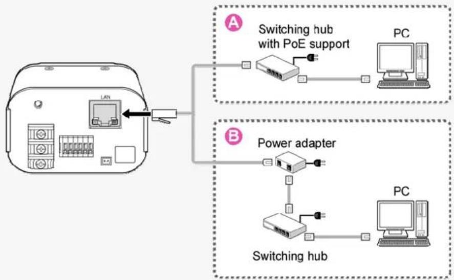
flowchart
graph TD
    A["Device 1"] -->|LAN| B["Switching hub with PoE support"]
    A --> C["Power adapter"]
    B --> D["PC"]
    C --> E["Switching hub"]
    E --> F["PC"]

Camera Monitor Connection
To perform focus adjustment with the camera, connect the supplied cable to the MONITOR OUT socket of the camera, and connect a monitor to the camera using a video cable.
After adjustment, be sure to remove the monitor cable.
Alarm Input/Output Terminal Connections
To connect a cable, while pushing the protrusion of the terminal, insert the cable into the opening and then release it.
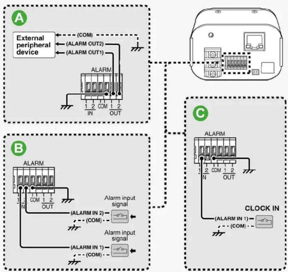
flowchart
graph TD
    subgraph_A["External peripheral device"]
        A1["ALARM"] -->|IN| A2["COM 1 2 OUT"]
        A2 -->|COM| A3["ALARM OUT1"]
        A3 -->|OUT| A4["External peripheral device"]
        A5["ALARM"] -->|IN| B1["COM 1 2 OUT"]
        B1 -->|COM| B2["ALARM OUT2"]
        B2 -->|OUT| B3["External peripheral device"]
    end

    subgraph_C["CLOCK IN"]
        C1["ALARM"] -->|IN| C2["COM 1 2 OUT"]
        C2 -->|COM| C3["ALARM OUT2"]
        C3 -->|OUT| C4["External peripheral device"]
        C5["ALARM"] -->|IN| C6["COM 1 2 OUT"]
        C6 -->|COM| C7["ALARM OUT2"]
        C7 -->|OUT| C8["External peripheral device"]
        C9["ALARM"] -->|IN| C10["COM 1 2 OUT"]
        C10 -->|COM| C11["ALARM OUT2"]
        C11 -->|OUT| C12["External peripheral device"]
        C13["ALARM"] -->|IN| C14["COM 1 2 OUT"]
        C14 -->|COM| C15["ALARM OUT2"]
        C15 -->|OUT| C16["External peripheral device"]
    end

Alarm Output Terminal Connection
Connect a buzzer, lamp, or other alarm device to one of the alarm output terminals (ALARM OUT1 or 2).

After connecting an alarm device, configure the output conditions for the corresponding alarm output terminal (ALARM OUT1 or 2) via network operation on the ALARM SETTINGS screen.

Alarm output terminal configuration is also possible via remote operation.

Alarm Input Terminal Connection
Connect an alarm switch, infrared sensor, or other external device to one of the alarm input terminals (ALARM IN1 or 2).

After connecting an alarm device, configure the input conditions for the corresponding alarm input terminal (ALARM IN1 or 2) via network operation on the ALARM SETTINGS screen.
To use the alarm input terminals as Day/Night switching terminals, follow the steps below. (This function is supported only by VCC-HD2300P/VCC-HD2300)
Under [DAY/NIGHT], set [DAY/NIGHT] to "COLOR" and select the terminal you want to use in [EXT ALARM].
On the ALARM SETTINGS screen, in [POLARITY], select the signal polarity of the alarm input terminal.

Alarm Input Terminal Connection for Clock Adjustment (CLOCK IN)
You can connect an external switch to the ALARM IN1 terminal and use that switch to adjust the camera's internal clock.

To do so, via network operation, configure the [CLOCK IN] setting on the CLOCK SETTINGS screen.
Lens Installation
Connect the lens cable plug to the auto iris lens socket provided on the left-side face of the camera. It is recommended that you use a CS-mount DC auto iris megapixel lens (optional).

text_image
LENS terminal for auto iris lens Brake coil (+) Brake coil (−) Drive coil (−) Drive coil (+) 5 mm max.
Keep the lens clean at all times.
The conversion ring (optional) is required to use a C-mount lens.
The lens cable plug must be changed if it does not fit into the auto iris lens socket. If so, contact the distributor from which you purchased the product (or the agent that provides the installation service).
Lens Adjustment
After installing the lens to the camera, you need to perform the following adjustments for the lens.
AFocus Adjustment (FOCUS ASSIST)
BFlange Back Adjustment
cIris Adjustment (IRIS)

Using network operation, you can use the focus assist function to adjust the focus.
You may also configure the back focus position switching mode to automatically adjust the back focus position when switching between the color and black-and-white video modes.
(This function is supported only by VCC-HD2300P/VCC-HD2300)

Focus Adjustment (FOCUS ASSIST)
Use the focus assist function to accurately focus on subject in high-resolution megapixel image because otherwise doing so would be extremely difficult.
If you are using a varifocal lens, adjust the focus using the following procedure.

If the focus assist function does not work properly because the camera produces too dark or too bright video images, perform iris adjustment ⓒ in advance.
The focus must be readjusted if the camera has lost focus due to difference in the subject distance or ambient temperature, the deterioration of the lens and installation environment, and the like that have been caused over the years.
Press the SET button for 2 seconds or more.
The monitor now shows the SELECT MENU screen.
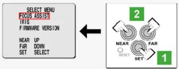
flowchart
graph TD
    A["SELECT MENU\nFOCUS ASSIST\nIRIS\nFIRMWARE VERSION\nNEAR UP\nFAR DOWN\nSET SELECT"] --> B["2\nNEAR\nRESET"]
    B --> C["1\n2\nFAIR\nSET"]

On the SELECT MENU screen, all information is displayed in English.
Select [FOCUS ASSIST] using the NEAR/FAR button and press the SET button.
The monitor now shows the focus adjustment screen.
Use the zoom lever of the lens to adjust the angle of view and the focus lever of the lens to set the FA bar (A) to the maximum level.
When the subject comes into focus, the color of the status indicator (B) "FOCUSING" turns from black to orange. If the use of the focus lever does not provide precise focusing, follow the "Fine-adjusting focus" procedure described below.
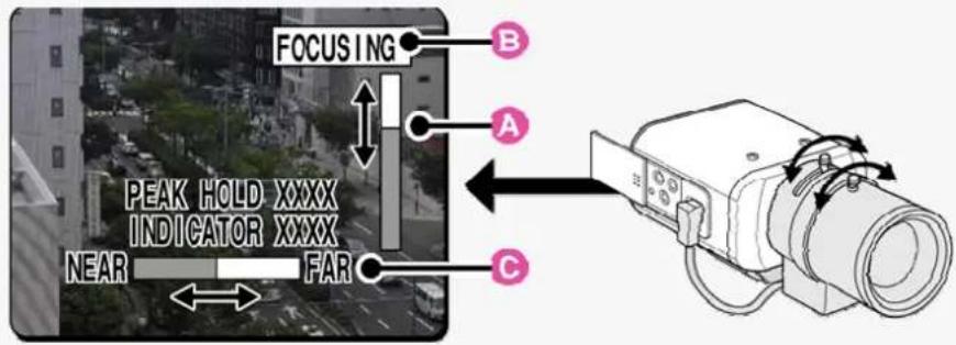
text_image
FOCUSING PEAK HOLD XXXX INDICATOR XXXX NEAR FAR A B C
PEAK HOLD: Shows the value of the maximum focus level.
INDICATOR: Shows the value of the current focus level.
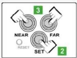
Fine-adjusting focus (using buttons provided on side face)
text_image
NEAR FAR SET 2 3 RESET1 Use the zoom lever of the lens to adjust the angle of view and the focus lever of the lens to roughly focus on the subject.
2Press the SET button.
The camera automatically focuses on the subject. Note that the color of the status indicator (B) "FOCUSING" turns from black to orange.
If the camera failes to focus on the subject, the FA bar (A) will not operate normally with the status indicator (B) showing "ERROR". In this case, manually adjust the focus (in Step 3).
3 Press the NEAR/FAR button to adjust the focus.
Pressing the button causes the back focus position to change, which is indicated in the FB bar gauge (C).
The position changes step by step each time the button is pressed and continuously at a high speed when the button is held down.

If you want to restore the default back focus position in re-adjustment, etc., press the NEAR and FAR buttons simultaneously.
While the camera is initializing the back focus position, the status indicator (B) shows "INITIALIZING".
4 Press the SET button for 2 seconds or more.
The focus adjustment screen will close.
The focus adjustment screen will also close automatically if left idle for 5 minutes or more.

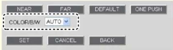
If video is out of focus in either color or black-and-white mode, perform the following steps to adjust the focus.
1 Confirm that [COLOR/B/W] is set to "AUTO" under [FOCUS ASSIST] on the CAMERA SETTINGS screen.
2Adjust the focus in color and black-and-white mode, respectively.
text_image
NEAR FAR DEFAULT ONE PUSH COLOR/BW AUTO SET CANCEL BACK
B Flange Back Adjustment
If you are using an optical zoom lens and zooming operation causes the camera to lose focus, adjust the flange back distance as follows.
1
Press the SET button for 2 seconds or more.
The monitor now shows the SELECT MENU screen.

text_image
SELECT MENU FOCUS ASSIST IRIS FIRMWARE VERSION NEAR UP FAR DOWN SET SELECT 2 3 4 1 NEAR FAR RESET SET FOCUSING PEAK HOLD XXXX INDICATOR XXXX NEAR FAR C
On the SELECT MENU screen, all information is displayed in English.
2
Select [FOCUS ASSIST] using the NEAR/FAR button and press the SET button.
The monitor now shows the focus adjustment screen.
3
Use the zoom and focus levers of the lens to focus on the subject at the telephoto end and press the NEAR/FAR button to adjust the focus.
Pressing the button causes the back focus position to change, which is indicated in the FB bar gauge (C). The position changes step by step each time the button is pressed and continuously at a high speed when the button is held down.
4
Use the zoom and focus levers of the lens to focus on the subject at the wide end and press the NEAR/FAR button to adjust the focus.
Repeat the above steps until switching between the telephoto and wide ends does not cause the camera to lose focus.
5 Press the SET button for 2 seconds or more.
The focus adjustment screen will close.

The focus adjustment screen will also close automatically if left idle for 5 minutes or more.

Iris Adjustment (IRIS)
If the camera produces too dark, too bright, or other incorrect video images, adjust the lens iris.
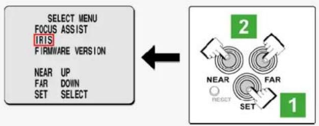
1 Press the SET button for 2 seconds or more.
The monitor now shows the SELECT MENU screen.
flowchart
graph LR
    A["SELECT MENU\nFOCUS ASSIST\nIRIS\nFIRMWARE VERSION\nNEAR UP\nFAR DOWN\nSET SELECT"] --> B["2\nNEAR\nFAIR\nRESET"]
    B --> C["1"]

On the SELECT MENU screen, all information is displayed in English.
2 Select [IRIS] using the NEAR/FAR button and press the SET button.
The monitor now shows the iris adjustment screen.
![SANYO VCC-HD2100P - Select [IRIS] using the NEAR/FAR button and press the SET button. - 1](/content/2026/05/817427/images/fb65073a7a7541dd73ca0c46640395acbe76a45406848ab8fd3c98ca283883f3.jpg)
text_image
IRIS LEVEL DARK LIGHT 40 NEAR LEFT FAR RIGHT NEAR FAR RESET SET3 Press the NEAR/FAR button to adjust the iris level.
The position changes step by step each time the button is pressed and continuously at a high speed when the button is held down.
NEAR: Closes the iris to produce darker images.
FAR: Opens the iris to produce brighter images.
4 Press the SET button for 2 seconds or more.
The iris adjustment screen will be closed.

The iris adjustment screen will also close automatically if left idle for 5 minutes or more.
Viewing Firmware Version
On the FIRMWARE VERSION screen, you can check the firmware version, IP address, and other information on the camera.

The firmware version can also be checked via network operation on the OPTION SETTINGS screen.
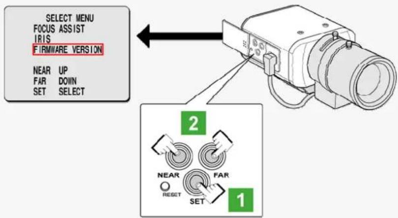
1 Press the SET button for 2 seconds or more.
The monitor now shows the SELECT MENU screen.
text_image
SELECT MENU FOCUS ASSIST IRIS FIRMWARE VERSION NEAR UP FAR DOWN SET SELECT 2 NEAR FAR RESET SET 1
On the SELECT MENU screen, all information is displayed in English.
2 Select [FIRMWARE VERSION] using the NEAR/FAR button and press the SET button.
The monitor now shows the FIRMWARE VERSION screen.
![SANYO VCC-HD2100P - Select [FIRMWARE VERSION] using the NEAR/FAR button and press the SET button. - 1](/content/2026/05/817427/images/3cdfebe9bcbcd61e5e85be990d5fe73a18189c90d2390a245a32ee960a6ac5f6.jpg)
text_image
FIRMWARE VERSION MAIN:1.00-00(090814-00) SUB :1.00-00(090814-00) IP ADDRESS 192.168.000.002 MAC ADDRESS XX:XX:XX:XX:XX3 Press the SET button for 2 seconds or more.
The FIRMWARE VERSION screen closes.

The FIRMWARE VERSION screen will close automatically if left idle for 5 minutes or more.
VCC-HD2300/HD2300P
VCC-HD2100/HD2100P
Chapter 2
Quick Operation Guide
From Connection to Network Operation
Live Video Monitoring
Alarm Detection and Output
Software Information
Configuration menu quick reference tables
From Connection to Network Operation
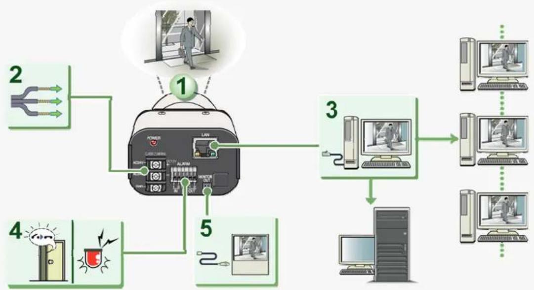
Follow the steps below to set up and connect the camera to your PC.
You can use alarm video recording, bidirectional audio communications, and other standard features of the camera, in addition to normal live video monitoring.
flowchart
graph TD
    A["1"] --> B["2"]
    A --> C["3"]
    A --> D["4"]
    A --> E["5"]
    B --> F["Power"]
    C --> G["Computer"]
    D --> H["Computer"]
    E --> I["Computer"]
    F --> J["LED Lighting & Alarm"]
    G --> K["Desktop Computer"]
    H --> L["Desktop Computer"]
    I --> M["Desktop Computer"]
1 Install the lens to the camera.
2 Connect the power cable to the power terminals.
Use a 24-VAC or 12-VDC power supply.

Do not turn on the camera until you complete all connections.
3 Connect the network (LAN) socket to your PC using a LAN cable.
Check the operating environment of your PC and perform the following operations:
Check the network information on your PC.
Install the "H.264 Plug-in" from the supplied CD-ROM onto your PC.
4 Connect necessary external devices to the alarm input/output terminals.
ALARM IN1/2 terminal: Connect an external switch, infrared sensor, or other device to detect alarm conditions such as entry of an intruder.
ALARM OUT 1/2: Connect a buzzer, lamp, or other alarm device to output a signal to warn people of the occurrence of an alarm condition.
5 Connect a monitor for focus adjustment to the monitor output socket.
Connect your monitor to the camera via the supplied video cable.
6 Turn on the camera.
The power indicator lights up and live video appears on the monitor.

To enable surveillance with clear video images, adjust the lens focus while viewing the subject on the FOCUS ASSIST screen displayed on the monitor.
After adjustment, be sure to remove the monitor cable.
7 Access the camera from your PC's Web browser.
Live video appears on the live screen. Now, you can perform all network operations from your PC.
Live Video Monitoring
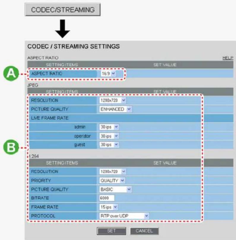
If you are operating the camera for the first time, check the factory default video/image conditions on the CODEC/STREAMING SETTINGS screen. Change the default settings as necessary.
For details, refer to the "CODEC/STREAMING SETTINGS" section.
text_image
CODEC/STREAMING CODEC / STREAMING SETTINGS ASPECT RATIO HELP SETTING ITEMS SET VALUE ASPECT RATIO 16:9 JPEG SETTING ITEMS SET VALUE RESOLUTION 1230x723 PICTURE QUALITY ENHANCED LIVE FRAME RATE admin 30 ips operator 30 ips guest 30 ips 1.264 SETTING ITEMS SET VALUE RESOLUTION 1230x720 PRIORITY QUALITY PICTURE QUALITY BASIC BITRATE 6000 FRAME RATE 15 ips PROTOCOL RTP over UDP SET CANCELA Configuring aspect ratio (ASPECT RATIO)
16:9 (Default) → 4:3
B Configuring videoImages (JPEG/H.264)
You can switch between JPEG image and H.264 video using the buttons on the live screen control panel. The screenshot above shows the factory default settings for each video/image condition.
Alarm Detection and Output
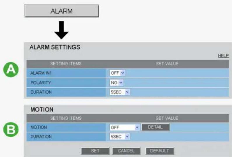
If you are operating the camera for the first time, check the factory default alarm detection conditions on the ALARM SETTINGS screen. Change the default settings as desired.
For details, refer to the "ALARM SETTINGS" section.
Alarm Detection
You can configure the camera to detect alarm conditions via the "alarm input terminals" or "built-in motion sensor".
For how to configure the camera to detect alarm conditions via the alarm input terminals, refer to the "Alarm Input/Output Terminal Connections" section.
text_image
ALARM ALARM SETTINGS HELP SETTING ITEMS SET VALUE ALARM IN1 OFF POLARITY NO DURATION 5SEC MOTION SETTING ITEMS SET VALUE MOTION OFF DETAIL DURATION 5SEC SET CANCEL DEFAULTA Detecting an Alarm Condition via Alarm Input Terminal
Connecting an alarm switch, infrared sensor, or other external device to the ALARM IN1/2 terminal enables the camera to detect alarm conditions such as entry of an intruder.
| Setting Item Default Setting Optional Setting | ||
| ALARM IN1/2 (Alarm input terminal number) | OFF (Disables alarm detection.) | ON (Enables alarm detection.) |
| POLARITY (Signal polarity) | NO (Ex.: Detects an alarm when door is closed) | NC (Ex.: Detects an alarm when door is opened.) |
| DURATION (Alarm retention duration) | 5SEC (Ex.: Records alarm video for 5 sec.) | 10SEC to 5MIN, CC (Retains the alarm state as long as the alarm signal persists.) |
B Detecting an Alarm Condition via Built-in Motion Sensor
The camera uses the built-in motion sensor to detect alarm conditions.
The motion sensor detects an alarm condition in two ways as follows.
| Setting Item Default Setting Optional Setting | ||
| MOTION (Use of built-in motion sensor) | OFF (Disables alarm detection.) | AMASKINGDETECT |
| DURATION (Alarm retention duration) | 5SEC (Ex.: Records alarm video for 5 sec.) | 10SEC to 5MIN, CC (Retains an alarm state as long as the motion alarm persists.) |
ADisabling motion detection in masked areas
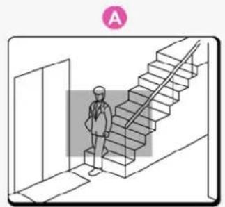
natural_image
Illustration of a person standing beside a staircase inside a room, with no visible text or symbols.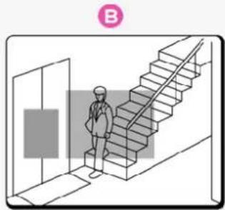
natural_image
Illustration of a person standing beside a staircase inside a hallway (no text or symbols)In [MOTION], after selecting a motion sensor type, click DETAIL to configure the detection conditions on the detailed configuration screen.
Alarm output
You can configure the camera to "automatically output alarm signals" or "remotely (manually) output alarm signals".
A Configuring Automatic Alarm Output
You can configure the camera to automatically output an alarm signal when either of its alarm input terminals receives an alarm signal.
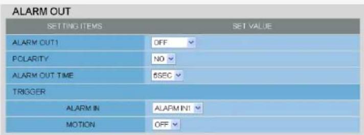
text_image
ALARM OUT SETTING ITEMS SET VALUE ALARM OUT1 OFF POLARITY N0 ALARM OUT TIME 5SEC TRIGGER ALARM IN ALARM INT MOTION OFF| Setting Item Default Setting Optional Setting | ||
| ALARM OUT1/2 (Alarm output terminal number) | OFF (Disables alarm output.) ON (Enables automatic alarm output.) | |
| POLARITY (Signal polarity) | NO NC | |
| ALARM OUT TIME (Alarm output time) | 5SEC (Ex.: Beeps a warning for 5 sec.) 10SEC to 5MIN | |
| ALARM IN (Output condition) | ALARM IN1 (Triggers alarm output when ALARM IN1 terminal receives an alarm signal.) | ALARM IN2 (Triggers alarm output when ALARM IN2 terminal receives an alarm signal.) |
| MOTION (Output condition) | OFF (Disables alarm output using motion sensor.) | ON (Triggers alarm output using motion sensor.) |
B Configuring Remote Alarm Output
Use the Remote Alarm buttons () provided on the live screen to send alarm signals from the camera's alarm output terminals.
| ALARM OUT | |
| SETTING ITEMS | SET VALUE |
| ALARM OUT1 | REMOTE |
| POLARITY | NO |
| ALARM OUT TIME | 5SEC |
| Setting Item Default Setting Optional Setting | ||
| ALARM OUT1/ 2 (Alarm output terminal number) | OFF (Disables alarm output.) | REMOTE (Enables remote alarm output.) |
| POLARITY (Signal polarity) NO NC | ||
| ALARM OUT TIME (Alarm output time) | 5SEC (Ex.: Beeps a warning for 5 sec.) | 10SEC to 5MIN, CC (Stops alarm output when Remote Alarm button is clicked.) |
Software Information
You can install the following software on your PC to extend the capabilities of your surveillance system.

The CD-ROM that comes with the camera includes all the supplied software.
Supplied Software
AH.264 Plug-in (Plug-in for monitoring live video as high-quality moving images)
This plug-in software is required to display H.264 video on the live screen. Be sure to install it on each computer from which you access the camera via network operation.
BVA-SW3050Lite (Application for monitoring live video from more than one camera)
This monitoring application is designed for use with SANYO network cameras.
You can access up to 128 cameras simultaneously.
The application lets you monitor video images from connected cameras in either the single screen or the 4-screen, 9-screen, or 16-split screen mode.
c Auto IP Setup (Utility for automatically setting up IP addresses when two or more new cameras are connected)
This utility automatically assigns a unique IP address to each camera that has the factory default IP address ("192.168.0.2").
Using the utility's camera search function, you can check the IP addresses of all cameras existing on the same local network.
It is also possible to check and correct overlapping IP addresses.
Optional Software
VA-SW3050Server/Client (Application for recording and playing back streaming images from camera)
This recorder/player application is designed for use with SANYO network cameras.
This is a complete version of the VA-SW3050 series software, which offers all the functions you need to perform monitoring, recording, search, playback, and other operations in a surveillance system.
This software requires at least two PCs that serve as the server and the client.
Configuration menu quick reference tables
Click MENU on the control panel to display the administrator configuration menu that includes a series of menu selection buttons.
If you are a surveillance system administrator, use these buttons to configure necessary settings according to the installation environment and application of your camera.
Configuration Related to Network Connection
| Operation Configuration Screen (Menu) | |
| Changing the camera's IP address. NETWORK SETTINGS | |
| Using SANYO's DDNS service. | |
| Using SSL communication. | |
| Streaming H.264 video in multicast |
Clock and Camera Title Configuration
| Operation Configuration Screen (Menu) | |
| Adjusting clock to specific time based on external input signal CLOCK SETTINGS | |
| Configuring the camera title |
Configuration Related to Access and Security
| Operation Configuration Screen (Menu) | |
| Changing the user password USER SETTINGS | |
| Allowing all users to access the camera without any authentication check | |
| Restricting PCs that have access to the camera SECURITY SETTINGS | |
Configuration Related to Live Video
| Operation Configuration Screen (Menu) | |
| Accessing the camera from video viewer or similar software to view live video | NETWORK SETTINGS |
| Hiding specific portions of video CAMERA SETTINGS (PRIVACY MASK) | |
Alarm-Related Configuration
| Operation Configuration Screen (Menu) | |
| Sending an alarm image via e-mail E-MAIL SETTINGS | |
| Using the alarm input terminals to switch the camera between the color and black-and-white video modes(This function is supported only by VCC-HD2300P/VCC-HD2300) | CAMERA SETTINGS (DAY/NIGHT) |
Recording-Related Configuration
| Operation Configuration Screen (Menu) | |
| Recording images from the camera to an FTP server FTP SETTINGS |
Optional Configuration
| Operation Configuration Screen (Menu) | |
| Updating the camera's firmware to the latest version. OPTION SETTINGS (FIRMWARE UPDATE) | |
| Restoring the factory default settings OPTION SETTINGS (FACTORY DEFAULT) | |
| Backing up or uploading settings OPTION SETTINGS (MENU BACKUP/MENU UPLOAD) | |
| Viewing the access log, system log, and operation log OPTION SETTINGS (LOG) |
VCC-HD2300/HD2300P
VCC-HD2100/HD2100P
Chapter 3
Before You Begin Network
Operation
Preparing Your Computer for Network Operation
Setting Up IP Addresses Automatically (Auto IP Setup)
Checking the operating environment
Configure the network information on your PC
Operation Privileges and Login Users
Preparing Your Computer for Network Operation
Follow the steps below to prepare your computer for network operation. For detailed procedure, refer to the linked information.
1 Assign a unique IP address to each camera.
If you have newly installed two or more cameras on your network, you can accomplish this by using the supplied "Auto IP Setup" software.
2 Check your operating environment
3 Connect the camera to the network to which your PC is also connected.
4 Configure the network information on your PC
You need to configure information such as the IP address of your PC.
5 Install the "H.264 Plug-in" from the supplied CD-ROM onto your PC.
Double-click the "setup.exe" icon and complete the steps in the wizard.
You are now ready to monitor the surveillance video in the H.264 format.

setup.exe
SANYO H.264 Plug-in Setup
SANYO
6 Access the camera from your Web browser.
From your Web browser (Internet Explorer), access the camera and log into the system as an "admin" user (administrator).
When you access the camera and log into the system, live video from the camera appears on the live screen.

If the live screen displays no or distorted video, check your operating environment and connection conditions.
8 Configure the necessary settings on the administrator configuration screens.
Although the camera is already configured with the factory default settings so that you can monitor live video immediately after you log into the system, you need to configure necessary settings according to your installation environment and application of the camera.

If this is the first access to the camera, start by configuring the system clock on the CLOCK SETTINGS screen.
9 Use associated software applications to extend the capabilities of your surveillance system.
Install the following associated software applications on your PC, as required:
VA-SW3050Lite (supplied): Monitor application for monitoring video images from more than one camera simultaneously on a multi-view screen.
VA-SW3050Server/Client (optional): Recorder/player application for recording and playing back streaming video data from the network.
Setting Up IP Addresses Automatically (Auto IP Setup)
If you are installing two or more new cameras on the same local network, you need to change the factory default IP address of each camera to prevent IP address overlap. The supplied "Auto IP Setup" software frees you from this burden by automatically assigning a unique IP address to each camera on your network.
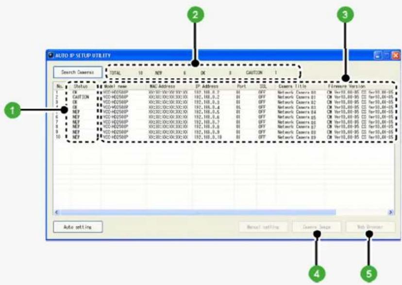
Before setting up the IP addresses automatically, click the [Search Cameras] button in the utility window to search all cameras on the network and display the address settings and details of each camera.
text_image
AUTO IP SETUP UTILITY Search Cameras TOTAL 10 NEP 6 OK 3 CAUTION 1 No. Status Model name MAC Address IP Address Port SQL Camera Title Firmware Version 1 CK VCX-HD2580P XC222-XX/XX/XX/XX 192,198,0.7 ## OFF Network Camera 00 CM Ver18,60-95 CI Per10,84-05 2 CAUTION VCX-HD2580P XC222-XX/XX/XX/XX 192,198,0.2 ## OFF Network Camera 01 CM Ver18,60-95 CI Per10,84-05 3 CK VCX-HD2580P XC222-XX/XX/XX/XX 192,198,0.3 ## OFF Network Camera 02 CM Ver18,60-95 CI Per10,84-05 4 CK VCX-HD2580P XC222-XX/XX/XX/XX 192,198,0.4 ## OFF Network Camera 03 CM Ver18,60-95 CI Per10,84-05 5 NEP VCX-HD2580P XC222-XX/XX/XX/XX 192,198,0.5 ## OFF Network Camera 04 CM Ver18,60-95 CI Per10,84-05 6 NEP VCX-HD2580P XC222-XX/XX/XX/XX 192,198,0.6 ## OFF Network Camera 05 CM Ver18,60-95 CI Per10,84-05 7 NEP VCX-HD2580P XC222-XX/XX/XX/XX 192,198,0.7 ## OFF Network Camera 06 CM Ver18,60-95 CI Per10,84-05 8 NEP VCX-HD2580P XC222-XX/XX/XX/XX 192,198,0.8 ## OFF Network Camera 07 CM Ver18,60-95 CI Per10,84-05 9 NEP VCX-HD2580P XC222-XX/XX/XX/XX 192,198,0.9 ## OFF Network Camera 08 CM Ver18,60-95 CI Per10,84-05 10 NEP VCX-HD2580P XC222-XX/XX/XX/XX 192,198,1.0 ## OFF Network Camera 09 CM Ver18,60-95 CI Per10,84-05 Auto setting Renai Setting Camera Setup Sub Driver1 Status
NEW: The camera has the default IP address ("192.168.0.2").
→ Assign a unique IP address.
OK: The camera has a unique IP address and can be connected successfully to network.
CAUTION: The camera cannot be connected successfully to the network because of IP address overlap or other reason.
→ Change the IP address.
2 Number of searched cameras (Total and by status)
3 Camera details

"Model name", "IP Address", "Port", "SSL", "Camera Title", and "Firmware Version" are not shown if the network board or other hardware is not supported.
"IP Address", "Port", "SSL", and "Camera Title" are editable. (Refer to the "Manually Setting Up IP Addresses of Existing Cameras" section.)
4 Camera Image button
Select the desired camera row and click this button. Then, video from the camera appears in a separate window. Use it to check which camera is selected or when editing the camera title or other data.
5 Web Browser button
Select the desired camera row and click this button. Then, the Web browser opens and connects to the camera automatically.
Automatically Setting Up IP Addresses of New Cameras
1 Insert the supplied CD-ROM into the CD-ROM drive of your PC.
The opening menu appears.
2 Click [Auto IP Setup].
The utility window opens so that you can search cameras.
![SANYO VCC-HD2100P - Click [Auto IP Setup]. - 1](/content/2026/05/817427/images/3491965ce314ac0393bdc9864ad8e5112db530136c07636235b2a9486cb90602.jpg)
If you encounter a firewall confirmation dialog box, disable the firewall so that your PC can communicate with the camera.
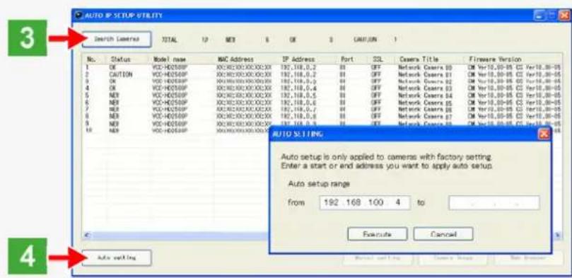
3 Click Search Cameras.
The utility searches all cameras on the local network and shows information on each camera one after another.
text_image
3 Search Camera TOTAL UP MEX 5 OR 3 CANNUN 1 No. Status Model name MAC Address EP Address Port SQL Camera Title Firmware Version 1 OK VCC-H02500P XDC8000000000X 197,118,0,2 B I OFF Network Camera 00 CM Yr10,00-05 CS Yer10,00-05 2 CAUTION VCC-H02500P XDC800000000X 197,118,0,2 B I OFF Network Camera 01 CM Yr10,00-05 CS Yer10,00-05 3 OK VCC-H02500P XDC800000000X 197,118,0,2 B I OFF Network Camera 02 CM Yr10,00-05 CS Yer10,00-05 4 OK VCC-H02500P XDC800000000X 197,118,0,4 B I OFF Network Camera 03 CM Yr10,00-05 CS Yer10,00-05 5 NEI VCC-H02500P XDC80000000X 197,118,0,5 B I OFF Network Camera 04 CM Yr10,00-05 CS Yer10,00-05 6 NEI VCC-H02500P XDC80000000X 197,118,0,6 B I OFF Network Camera 05 CM Yr10,00-05 CS Yer10,00-05 7 NEI VCC-H02500P XDC80000000X 197,118,0,7 B I OFF Network Camera 06 CM Yr10,00-05 CS Yer10,00-05 8 NEI VCC-H02500P XDC8000000X 197,118,0,8 B I OFF Network Camera 07 CM Yr10,00-05 CS Yer10,00-05 9 NEI VCC-H02500P XDC800000X 197,118,9 B I OFF Network Camera 28 CM Yr10,25-25 CS Yer12,25-25 18 NEI VCC-HD544P XDC82333333333333333333333333333333333333333333333333333333333333333333333333 AUTO SETTING Auto setup is only applied to cameras with factory setting. Enter a start or end address you want to apply auto setup. Auto setup range from 192 168 100 4 to Extrute Cancel Auto settingThe above screenshot shows an example when your PC is connected to 10 cameras.
4 Click Auto setting and, in the address range selection dialog box, click EXECUTE.
The utility automatically assigns a series of new IP addresses, starting from the start address.

The dialog box initially shows, as the start IP address, the IP address to be assigned to the first camera that has a status of "NEW".
To specify your own address range, type both the start and end IP addresses.
The utility automatically assigns an IP address to each camera located in the LAN, but not beyond the router.
It skips any IP address that is already used.
Manually Setting Up IP Addresses of Existing Cameras
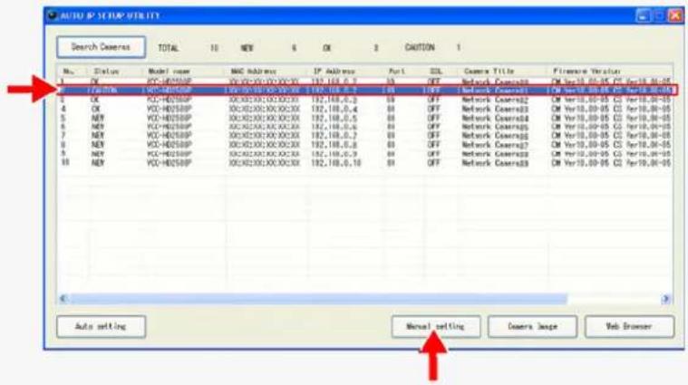
If you find that the searched cameras have overlapping IP addresses (indicated by a status of "CAUTION") or if you need to change a camera title, you can edit the displayed camera data manually as described below.
text_image
AUTO IP STOP UTILITY Search Camera TOTAL 10 NEW 6 OK 3 CANTON 1 No. Status Model name MAC Address IP Address Port SQL Camera Title Camera Version 1 PE VCC-H250BP VCCX200X00X00X 192,188,0.7 05 OFF Network Coverage CM Ver10,00-05 CS Per10,00-05 2 FUTTER VCC-H250BP VCCX200X00X00X 192,188,0.6 05 OFF Network Coverage CM Ver10,00-05 CS Per10,00-05 3 OK VCC-H250BP XCCX200X00X00X 192,188,0.3 05 OFF Network Coverage CM Ver10,00-05 CS Per10,00-05 4 OK VCC-H250BP XCCX200X00X00X 192,188,0.4 05 OFF Network Coverage CM Ver10,00-05 CS Per10,00-05 5 KEY VCC-H250BP XCCX200X00X00X 192,188,0.5 05 OFF Network Coverage CM Ver10,00-05 CS Per10,00-05 6 KEY VCC-H250BP XCCX200X00X00X 192,188,0.6 05 OFF Network Coverage CM Ver10,00-05 CS Per10,00-05 7 KEY VCC-H250BP XCCX200X00X00X 192,188,0.7 05 OFF Network Coverage CM Ver10,00-05 CS Per10,00-05 8 KEY VCC-H250BP XCCX200X00X00X 192,188,0.8 05 OFF Network Coverage CM Ver10,00-05 CS Per10,00-05 9 KEY VCC-H250BP XCCX200X00X00X 192,188,0.9 05 OFF Network Coverage CM Ver10,00-05 CS Per10,00-05 10 KEY VCC-H250BP XCCX250X00X33X 192,188,5.18 05 OFF Network Coverage CM Ver10,00-05 CS Per19,99-96 Auto setting Manual setting Camera Image Web Browser1 Select the desired camera and click Manual setting.
The camera information dialog box opens.
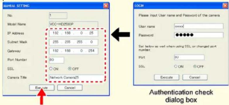
2 Make changes to the camera data and click EXECUTE.
This transmits your changes to the camera.
You can see the problem of IP address overlap has been resolved in the [Status] row of the list, which has been changed from "CAUTION" to "OK".

You cannot change the model name.
If your login user name and password has been changed from the factory default settings, you will be presented with an authentication check dialog box. In this case, type the current user name and password.
text_image
MANUAL SETTING No. 1 Model Name VCC-HD2500P IP Address 192 198 0 25 Submit Mask 255 255 255 0 Gateway 192 198 0 254 Port Number 80 SSL ON OFF Camera Title Network Camera25 Execute Cancel LOGIN Please input User name and Password of the camera. User name xxxx Password ••••••• Set below as well when using SSL or changed port number. Port 3U SSL ON OFF Execute Cancel Authentication check dialog boxIf SSL communication is enabled for the selected camera, you cannot edit the camera data. Change the SSL and port number settings in the authentication check dialog box.
Checking the operating environment
To operate the camera via network operation, you must meet the following operating requirements.
PC: IBM PC/AT compatible
Operating system: Windows XP Professional/Windows Vista
CPU: Core2Duo E6700 2.66 GHz or higher
Memory: Windows XP: 1GB or more
Windows Vista: 2GB or more
Network interface: 10BASE-T/100BASE-TX (RJ-45 connector)
Display card: 1920×1200 pixels or higher
Graphics chip: ATI RADEON HD2600 series or higher nVIDIA GeForce 8600 series or higher nVIDIA Quadro FX550 series or higher
Web browser: Internet Explorer Ver. 6.0 SP2 or higher, or Internet Explorer Ver. 7.0

Use a LAN cable no longer than 100 m (109.4 yards) with the shield type CAT5 or higher.
The live video may be delayed depending on your system environment.
Use Windows Update to keep the operating system and browser up-to-date.
Note, however, that Internet Explorer 8 is not supported.
Configuring the Web Browser
In the cases below, configure the Internet Explorer's settings by clicking [Tool] and then [Internet Options].
When accessing the camera using SSL encryption for video signal transmission
1 Click the [Advanced] tab.
2 Make sure that the [Use SSL 2.0] and [Use SSL 3.0] check boxes under [Security] are selected. If deselected, select them.
When the video refresh is unstable
1 Click the [General] tab.
2 Under [Temporary Internet Files], click [Settings].
For Windows Vista, click [Settings] under [Browsing history].
3 Set the slider under [Amount of disk space to use:] to a low value (the minimum value recommended by Microsoft).
When a Java Script "Runtime Error" is displayed during operation
1 Click the [Advanced] tab.
2 Under [Browsing], deselect the [Display a notification about every script error] check box.
3 Select the [Disable script debugging] check box.
Configure the network information on your PC
For Windows XP
1 In [Control Panel], click [Network and Internet Connections].
The [Network and Internet Connections] dialog box opens.
![SANYO VCC-HD2100P - In [Control Panel], click [Network and Internet Connections]. - 1](/content/2026/05/817427/images/d3a467c72b1ede082a8cea5d45ec315567122d8fc0bfe6439726292c2ad78bba.jpg)
text_image
Pick a category Appearance and Themes Network and Internet Connections Printers and Other Hardware User Accounts Add or Remove Programs Date, Time, Language, and Regional Options Sounds, Speech, and Audio Devices Accessibility Options Performance and Maintenance Security Center2 Click [Network Connections].
The [Network Connections] dialog box opens.
Under [LAN or High-Speed Internet], the icon representing your LAN interface (Ethernet adapter) configuration appears.
![SANYO VCC-HD2100P - Click [Network Connections]. - 1](/content/2026/05/817427/images/da0815f6391a7593ac5dfb5318cc1503c85a6ba1ea4944ae964ed7252067169a.jpg)
text_image
Pick a task... → Set up or change your Internet connection → Create a connection to the network at your workplace → Set up or change your home or small office network → Set up a wireless network for a home or small office → Change Windows Firewall settings or pick a Control Panel icon Internet Options Network Setup Wizard Wireless Network Setup Wizard Network Connections Windows Firewall3 Right-click on the LAN interface (Ethernet adapter) configuration icon and click [Properties] in the context menu.
The [Local Area Connection Properties] dialog box opens, with the [General] tab shown.
![SANYO VCC-HD2100P - Right-click on the LAN interface (Ethernet adapter) configuration icon and click [Properties] in the context menu. - 1](/content/2026/05/817427/images/31e1121092eff064b38e2df54208b2e1edcbc17bb29f8081aebdb5a9421f8039.jpg)
text_image
LAN or High-Speed Internet Local Area Connection 2 Disable Status Repair Bridge Connections Create Shortcut Delete Rename Properties Local Area Connection Connected, Firewalled 3Com EtherLink XL 10/100 PCI...4 In the [This connection uses the following items:] list box, select the [Internet Protocol (TCP/IP)] check box.
Confirm that the [Internet Protocol (TCP/IP)] check box is selected. If deselected, select the check box.
![SANYO VCC-HD2100P - In the [This connection uses the following items:] list box, select the [Internet Protocol (TCP/IP)] check box. - 1](/content/2026/05/817427/images/b0d940d9a26492b6a8a82d623600df6e023c6e695c8e45724259dd0616ef4ff3.jpg)
text_image
Local Area Connection 2 Properties General Authentication Advanced Connect using: Intel(R) PRO/100 S Desktop Adapter Configure... This connection uses the following items: ✓ Client for Microsoft Networks ✓ File and Printer Sharing for Microsoft Networks ✓ QoS Packet Scheduler Internet Protocol (TCP/IP) Install... Uninstall Properties Description Transmission Control Protocol/Internet Protocol. The default wide area network protocol that provides communication across diverse interconnected networks. Show icon in notification area when connected ✓ Notify me when this connection has limited or no connectivity OK Cancel5 Click [Properties].
The [Internet Protocol (TCP/IP) Properties] dialog box opens, with the [General] tab shown.
6 Select the [Use the following IP address:] radio button and specify the IP address, the subnet mask, and the default gateway.
![SANYO VCC-HD2100P - Select the [Use the following IP address:] radio button and specify the IP address, the subnet mask, and the default gateway. - 1](/content/2026/05/817427/images/78ab93024055c9a3f44c464bc5c1c20f4ef3a0e464e3c40a7621b35d781208cb.jpg)
text_image
Internet Protocol [TCP/IP] Properties General You can get IP settings assigned automatically if your network supports this capability. Otherwise, you need to ask your network administrator for the appropriate IP settings. Obtain an IP address automatically Use the following IP address: IP address: 192 . 168 . 0 . 250 Subnet mask: 255 . 255 . 255 . 0 Default gateway: 192 . 168 . 0 . 1 Obtain DNS server address automatically Use the following DNS server addresses: Preferred DNS server: Alternate DNS server: Advanced OK Cancel7 Check the configured settings and click OK.
You are now done with the TCP/IP configuration.
Close all the dialog boxes that are open.
For Windows Vista
1 In [Control Panel], click [Network and Sharing Center].
The [Network and Sharing Center] dialog box opens.
![SANYO VCC-HD2100P - In [Control Panel], click [Network and Sharing Center]. - 1](/content/2026/05/817427/images/e763bcbc2d7f58e547d31fd88d720cca0e73cad4d38edbfc9524ca334e69bd91.jpg)
text_image
Network and Internet Network and Sharing Center Search Tasks View computers and devices Connect to a network Set up a connection or network Manage network connections Diagnose and share Network and Sharing Center USER1-PC (This computer) View full map Network Internet Network (Private network) Customize Access Local and Internet Connection Local Area Connection View status Sharing and Discovery Network discovery ● On File sharing ● On Public folder sharing ● Off Printer sharing ● Off (no printers installed) Password protected sharing ● On Media sharing ● Off Show me all the files and folders I am sharing Show me all the shared network folders on this computer2 Click [Manage network connections].
The [Network Connections] dialog box opens.
![SANYO VCC-HD2100P - Click [Manage network connections]. - 1](/content/2026/05/817427/images/e8b913512ad6734df32810ba57d5d2ccdc2f1f272dc4ce9da3552137d0afc98a.jpg)
text_image
Network and Internet ▶ Network Connections ▶ Search Organize ▼ Views ▼ Name Status Device Name Connectivity Network Category Owner Type Phone # or Host Addre... LAN or High-Speed Internet (1) Local Area Connection Network Realtime: 0168B/0111B Fa...3 Double-click [Local Area Connection].
The [Local Area Connection Status] dialog box opens.
![SANYO VCC-HD2100P - Double-click [Local Area Connection]. - 1](/content/2026/05/817427/images/94efeab57ae9c33ae0896950a0c8497a30483453c448a8978b9632cf50499cf3.jpg)
text_image
Local Area Connection Status General Connection IPv4 Connectivity: Internet IPv6 Connectivity: Limited Media State: Enabled Duration: 00:16:24 Speed: 1.0 Gbps Details... Activity Sent — Received Bytes: 5,814,496 | 373,074 Properties Disable Diagnose Close4 Click [Properties] and, in the confirmation dialog box, click [Continue].
The [Local Area Connection Properties] dialog box opens.
5 Select the [Internet Protocol Version 4 (TCP/IPv4)] check box.
Confirm that the [Internet Protocol Version 4 (TCP/IPv4)] check box is selected. If deselected, select the check box.
![SANYO VCC-HD2100P - Select the [Internet Protocol Version 4 (TCP/IPv4)] check box. - 1](/content/2026/05/817427/images/c99cbeb0a679eed13be685276eff8a78d76037992927f61398748f4186684120.jpg)
text_image
Local Area Connection Properties Networking Connect using: Realtek RTL8168B/8111B Family PCI-E Gigabit Ethernet Configure... This connection uses the following items: Client for Microsoft Networks QoS Packet Scheduler File and Printer Sharing for Microsoft Networks Internet Protocol Version 6 (TCP/IPv6) Internet Protocol Version 4 (TCP/IPv4) Link-Layer Topology Discovery Mapper I/O Driver Link-Layer Topology Discovery Responder Install... Uninstall Properties Description Transmission Control Protocol/Internet Protocol. The default wide area network protocol that provides communication across diverse interconnected networks. OK Cancel6 Click [Properties].
The [Internet Protocol Version 4 (TCP/IPv4) Properties] dialog box opens, with the [General] tab shown.
7 Select the [Use the following IP address:] radio button and specify the IP address and the subnet mask.
![SANYO VCC-HD2100P - Select the [Use the following IP address:] radio button and specify the IP address and the subnet mask. - 1](/content/2026/05/817427/images/2605d583d083e21ed59bbdb771db58c42d23412208a689b4e732d366ab3a5cfb.jpg)
text_image
Internet Protocol Version 4 (TCP/IPv4) Properties General You can get IP settings assigned automatically if your network supports this capability. Otherwise, you need to ask your network administrator for the appropriate IP settings. Obtain an IP address automatically Use the following IP address: IP address: 192 . 168 . 0 . 250 Subnet mask: 255 . 255 . 255 . 0 Default gateway: 192 . 168 . 0 . 1 Obtain DNS server address automatically Use the following DNS server addresses: Preferred DNS server: . Alternate DNS server: . Advanced... OK Cancel8 Check the configured settings and click OK.
You are now done with the TCP/IP configuration.
Close all the dialog boxes that are open.
Operation Privileges and Login Users
Operation Privileges
The operation privileges of users who perform network operation are divided into 3 levels (admin, operator, and guest). Each user who attempts to access the camera will be authenticated by the user name and password at login and granted an appropriate operation privilege.
| Operation | Operation Privileges | ||
| admin operator | guest | ||
| Monitor live video. ○ | ○ | ||
| Switching between JPEG image and H.264 video | ○ | ○ | ○ |
| Selecting H.264 video stream protocol | ○ | ○ | - |
| Changing the user password | ○ | ○ | - |
| Configuring settings ○ | △ | - | |
○ : Available
△: Available (Excluding NETWORK SETTINGS)
-: Unavailable
Disabling authentication check at login
You may set [ANONYMOUS USER LOG IN] to "ON" on the USER SETTINGS screen to allow anyone to access the camera without any authentication check at login.

In this case, all login users are regarded as guest users.
This means that users will be presented with an authentication check dialog box if they attempt to perform any operation beyond the guest user privilege and must enter an adequate user name and password to proceed.
Login User
Login is permitted to the following 5 users.
When you access the camera for the first time, log in as an admin user.
| Operation Privileges | User Password (Default) | |
| admin admin admin | ||
| admin2 admin2 | ||
| admin3 admin3 | ||
| operator operator operator | ||
| guest guest guest | ||

Update your password periodically for security reasons.
For details, refer to the "USER SETTINGS" section.
Limitation of Simultaneous Connections
Up to 20 users have access to one camera at a time.

If two or more users with the same operation privilege, for example, two admin users, log into the system, the user who log in last will take precedence.
If you need to limit the PCs allowed (or disallowed) to access the camera for security reasons, you can register the IP addresses of those PCs on the SECURITY SETTINGS screen.
Updating of live video may become slower depending on your system environment as the number of login users increases.
The number of users who can connect to the system simultaneously may be limited depending on the display resolution setting.
Using the supplied "VA-SW3050Lite" monitoring software or the optional "VA-SW3050 Server/Client" recording/playback software also provides simultaneous access to the camera from your Web browser. However, if the user who is using the software configures one of the following settings, the Web-based admin user will be disconnected from the camera.
Camera Setting
Normal Recording & Live Setting (JPEG)
Live Setting (H.264)
Alarm Setting
VCC-HD2300/HD2300P
VCC-HD2100/HD2100P
Chapter 4
Working with Live Screen
Access the camera from your Web browser
Live Screen Components
Control panel
Tool panel
Access the camera from your Web browser
1 Start Internet Explorer.
The supported Web browser is Internet Explorer Ver.6.0 SP2 or higher, or Internet Explorer Ver.7.0.
2 In the address bar, type the IP address of the camera and press [Enter] key.
When you access the camera, the login screen appears.
If this is the first access to the camera, in the Address bar, enter the default IP address as follows.
Address
http://192.168.0.2/
![SANYO VCC-HD2100P - In the address bar, type the IP address of the camera and press [Enter] key. - 1](/content/2026/05/817427/images/1affe583578f8f71643dedebe0ceb9446d37bbcdc696747ddc713340974e293f.jpg)
If you set [SSL] to "ON", before the IP address, type "https://" (instead of "http://").
Attempts to access the camera using the default IP address will fail if that address is already being used by another device in the network.
If so, change the IP address of the existing device before accessing the camera.
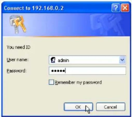
3 Type your user name and password and click OK.
The language selection screen appears.
text_image
Connect to 192.168.0.2 You need ID User name: admin Password: •••••• Remember my password OK Cancel
If this is the first access to the camera, log in as an admin user (administrator) using the following default authentication information.
4 Click the button corresponding to the language you want to use.
The live screen appears.
From the second login onwards, the live screen appears automatically by skipping the language selection screen.
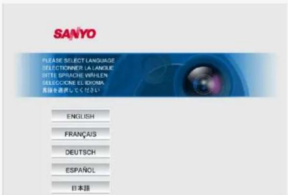
English, French, German, Spanish, Japanese

You can display the language selection screen by using the LANGUAGE button on the live screen control panel.
If this is the first access to the camera, configure the system clock on the CLOCK SETTINGS screen.
Accessing Two or More Cameras Simultaneously
You can access only one camera at a time from your Web browser.
To access two or more cameras from your PC simultaneously, use the following software.
Monitoring software "VA-SW3050Lite" (Supplied)
Installing this software adds to your PC the capability to simultaneously access two or more cameras and monitor live video from all connected cameras on a multi-view screen.
Recording software "VA-SW3050Server/Client" (Optional)
This software is higher-grade software than "VA-SW3050Lite" that adds recording and playback capabilities to your PC, in addition to video image monitoring.
This software requires at least two PCs that serve as the server and the client, respectively.
Live Screen Components
When you access and log into the camera successfully, the live screen appears.
For details, refer to the linked information.
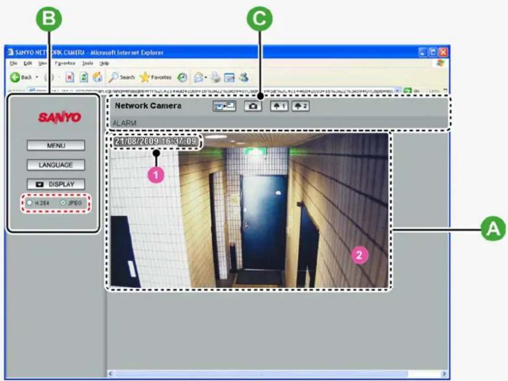
Video display area ( A )
Control Panel (B)
Tool Panel (c)
text_image
SANYO NETWORK CAMERA - Microsoft Internet Explorer Back Network Camera ALARM 21/08/2009 16:37:09 1 2 A B C SANYO MENU LANGUAGE DISPLAY H.284 JPEGVideo display area (A)
1 Current date and time
Shows the current date and time based on the clock settings configured on the CLOCK SETTINGS screen.

You may change the date-time format (month/day/year, year/month/day, or day/month/year), clock type, character size, and display position on the CLOCK SETTINGS screen.
2Video/image display
Shows JPEG images or H.264 video.
To switch the display, select the desired video/image display using the radio buttons on the live screen control panel.
Control panel
Click the desired button depending on the purpose of your operation. Then, the corresponding screen and panels will appear.
For details, refer to the linked information.
MENU: Click this to display the configuration menu.
LANGUAGE: Click this to display the language selection screen.
DISPLAY: Click this to display the display control panel.
Displaying Configuration Menu (MENU)
Click MENU on the control panel to display the configuration menu that includes a series of menu selection buttons.
Clicking one of these menu selection buttons displays the corresponding configuration screen.
If you are a surveillance system administrator, use these buttons to configure necessary settings according to the installation environment and application of your camera.

Required operation privilege: admin, operator ("admin" only for NETWORK SETTINGS screen) Without the required operation privilege, you will be presented with an authentication check dialog box when you click MENU on the live screen. In this case, you cannot access the menu selection buttons until you enter an adequate user name and password.
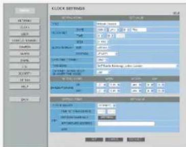
text_image
CLOCK SETTINGS TIME 10:00 24:00 30:00 35:00 40:00 45:00 50:00 55:00 60:00 65:00 70:00 75:00 80:00 85:00 90:00 95:00 100:00 105:00 110:00 115:00 120:00 125:00 130:00 135:00 140:00 145:00 150:00 155:00 160:00 165:00 170:00 175:00 180:00 185:00 190:00 195:00 200:00 205:00 210:00 215:00 220:00 225:00 230:00 235:00 240:00 245:00 250:00 255:00 260:00 265:00 270:00 275:00 280:00 285:00 290:00 295:00 300:00 305:00 310:00 315:00 320:00 325:00 330:00 335:00 340:00 345:00 350:00 355:00 360:00 365:00 370:00 375:00 380:00 385:00 390:00 395:00 400:00 405:00 410:00 415:00 420:00 425:00 430:00 435:00 440:00 445:00 450:00 455:00 460:00 465:00 470:00 475:00 480: 1.2V 1.6V 2.1V 2.6V 3.1V 3.6V 4.1V 4.6V 5.1V 5.6V 6.1V 6.6V 7.1V 7.6V 8.1V 8.6V 9.1V 9.6V 1.2V 1.6V 2.1V 2.6V 3.1V 3.6V 4.1V 4.6V 5.1V 5.6V 6.1V 6.6V 7.1V 7.6V 8.1V 8.6V 9.1V 8.6V 9.1V 9.6V 1.2V 1.6V 2.1V 2.6V 3.1V 3.6V 4.1V 4.6V 5.1V 5.6V 6.1V 6.6V 7.1V 7.6V 8.1V 8.6V 8.9V 9.9V 1.2V 1.6V 2.1V 2.6V 3.1V 3.6V 4.1V 4.6V 5.1V 5.6V 6.1V 6.6V 7.1V 7.6V 8.9V 9.9V 1.2V 1.6V 2.1V 2.6V 3.1V 3.6V 4.1V 4.6V 5.1V 5.6V 6.1V 6.6V 7.1V 7.6V 8.9V 9.9V 1.2V 2.6V 3.1V 3.6V 4.1V 4.6V 5.1V 5.6V 6.1V 6.6V 7.1V 7.6V 8.9VMenu Selection Buttons
| Button Configuration Screen (Menu) Operation | |||
| 1 | NETWORK NETWORK SETTINGS Configure the network settings of the camera. | ||
| 2 | CLOCK CLOCK SETTINGS Configure the clock date/time, daylight saving mode, automatic clock adjustment, and other settings. | ||
| 3 | USER USER SETTINGS Configure the user authentication check at login. | ||
| 4 | CODEC/STREAMING CODEC/STREAMING SETTINGS | Configure the conditions of the video/image transmission. | |
| 5 | CAMERACAMERA SETTINGS Configure the monitoring conditions and other settings according to the installation environment of the camera. | ||
| 6 | ALARM ALARM SETTINGS Configure the alarm input/output settings and the motion sensor function. | ||
| 7 | E-MAIL SETTINGS | Configure the alarm notification e-mail function and other automatic transmission settings. | |
| 8 | FTP | FTP SETTINGS | Configure the image streaming conditions if you intend to record images from the camera to an FTP server. |
| 9 | SECURITY | SECURITY SETTINGS | Configure the security settings for permitting or rejecting the access to the camera from up to 10 PCs. |
| 10 | OPTION | OPTION SETTINGS | Perform operations such as updating the firmware, restoring the factory defaults, and backing up and uploading settings. |
Other Buttons
| Operation Buttons | Function | |
| 1 | HELP | Provides an explanation of each function. |
| 2 | LIVE | Closes the configuration screen and returns to the live screen. |
Language Selection (LANGUAGE)
Click LANGUAGE on the control panel to display the language selection screen.
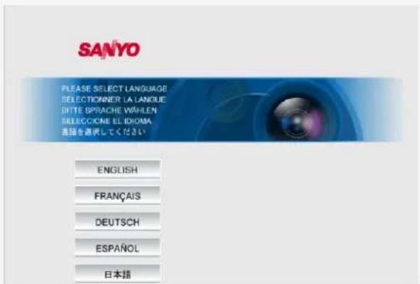
English, French, German, Spanish, Japanese

When the language selection screen appears, select the desired language within 10 seconds. Otherwise, you will be brought back to the live screen with the previous language setting.
Display Control Panel (DISPLAY)
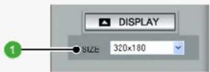
Click DISPLAY on the control panel to bring up the display control panel.
Panel is minimized. Clicking the button opens the panel.
: Clicking the button closes the panel.
text_image
DISPLAY SIZE: 320x180SIZE
The available options vary depending on your selection in [ASPECT RATIO] and your image/video compression format (JPEG/H.264).
JPEG (16:9): 1920×1080, 1280×720, 1024×576, 640×360
JPEG (4:3): 2288×1712, 1600×1200, 1280×960, 1024×768, 800×600, 640×480, 320×240
H.264 (16:9): 1920×1080, 1280×720, 640×360, 320×180
H.264 (4:3): 1600×1200, 1280×960, 1024×768, 640×480, 320×240
Tool panel
text_image
1 2 3 4 6 Microsoft Internet Explorer Search Favorites log?lang=eng print=Fri%2C+21+Aug+2009+16%3A22* 3A59+UTO print1y=5at* 2C+21+Aug+2010+16%3A22%3A59+UTO8pg=08s Go Links Network Camera ALARM1 Camera Title
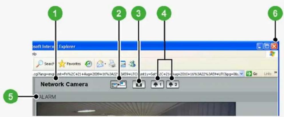
Shows the camera title you configured in [TITLE] on the CLOCK SETTINGS screen. The default camera title is "Network Camera".
The color of the camera title changes depending on the alarm state as follows:
Gray: Normal state
Red: Alarm condition is being detected.

When the camera title is shown in red, no other alarm signal will be received.
2 Full Screen Button ( )
Click this button to hide the control panel and the tool panel, and enlarge the video display to the maximum display area of the screen.
Clicking the button again restores the normal screen.
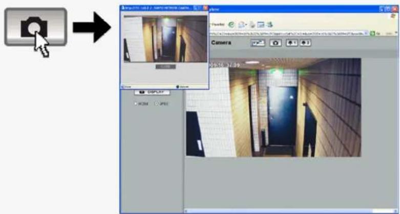
3 Capture Button (☐)
Click this button to capture the desired scene of the JPEG live streaming as a still image in a separate window. You can then save and print the captured image.
For details, refer to the "Printing and Saving a Still Image" section.
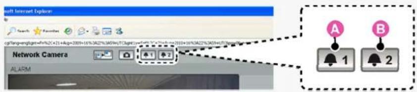
4 Remote Alarm Buttons (♠ 1 ♠ 2)
You can use these buttons to output an alarm signal from the camera.
For details, refer to the "Sending a Remote Alarm Signal" section.
5 [ALARM] Indication
The color of the letters changes to orange when an alarm is detected.
6 Close Button (×)
Click this button to disconnect your PC from the camera and close the browser window.
Printing and Saving a Still Image
You can capture and then save or print the desired scene of the JPEG live streaming during monitoring.
1 Click the Capture button on the tool panel.
The captured still image appears in a separate window.

This button is not available when you are monitoring H.264 video.
When a captured still image is shown, the live screen continues to display moving images in the video display area.
text_image
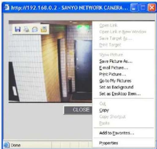
Screenshot of a photo editing software interface showing camera operation with tool and display panels2 Right-click on the captured still image and, in the context menu, select the command (Save Picture As/Print Picture).
In the dialog box that opens, specify the printing/saving conditions and then execute the command.
text_image
http://192.168.0.2 - SANYO NETWORK CAMERA... Open Link Open Link in New Window Save Target As... Print Target Show Picture Save Picture As... E-mail Picture... Print Picture... Go to My Pictures Set as Background Set as Desktop Item... Cut Copy Copy Shortcut Paste Add to Favorites... Properties CLOSE Done3 Click Close.
The window showing the captured still image closes.
Sending a Remote Alarm Signal
Use the Remote Alarm buttons provided on the live screen to send alarm signals from the camera's alarm output terminals.

Required operation privilege: admin, operator1, operator2

To use the remote alarm buttons, you must set in advance [ALARM OUT] to "REMOTE" and [ALARM OUT TIME] to the desired duration on the ALARM SETTINGS screen (administrator configuration menu).
1 Starting alarm signal output
Click one of the remote alarm buttons (shown in gray). The button turns orange and an alarm signal is output from the corresponding terminal.
If the camera is connected to a buzzer or other external device, you will hear an alarm sound from that device.
text_image
Soft Internet Explorer Search Favorites CP30Long=englog=49%2C+21+Aug=2009+16%3A22%3A59+UTChag=wr=49.2-10.2-10.2-10.2-10.2-10.2-10.2-10.2-10.2-10.2-10.2-10.2-10.2- Network Camera ALARM 单 1 单 2 A B 1 2A: Click this to send an alarm signal from the ALARM OUT1 terminal.
B: Click this to send an alarm signal from the ALARM OUT2 terminal.
2 Stopping alarm signal output
The way you stop alarm signal output differs depending on the [ALARM OUT TIME] setting on the ALARM SETTINGS screen.
Automatic Stop
The automatic stop method is applied if you have specified an alarm output duration in [ALARM OUT TIME]. When the set output duration has elapsed, the camera stops sending the alarm signal automatically and the button returns to white.
Manual Stop
The manual stop method is applied if you have selected "CC" in [ALARM OUT TIME]. Click one of the remote alarm buttons shown in orange. Then, the camera stops outputting the signal and the button returns to white.
VCC-HD2300/HD2300P
VCC-HD2100/HD2100P
Chapter 5
Working with Administrator
Configuration Screens
NETWORK SETTINGS
CLOCK SETTINGS
USER SETTINGS
CODEC/STREAMING SETTINGS
CAMERA SETTINGS
ALARM SETTINGS
E-MAIL SETTINGS
FTP SETTINGS
SECURITY SETTINGS
OPTION SETTINGS
NETWORK SETTINGS
Click NETWORK in the configuration menu to display the NETWORK SETTINGS screen.
On this screen, configure the following settings as required.
A Configuring basic network settings (NETWORK)
B Configuring DDNS setting (DDNS)
Configuring HTTP settings
D Configuring RTSP/RTP settings
E Configuring access name settings (ACCESS NAME)
F Multicast settings (MULTICAST)

Required operation privilege: admin
Before attempting to configure these network settings, contact your network administrator.
A Configuring Basic Network Settings
Configure the environment required to connect to the camera via the network by specifying the IP address, subnet mask, and other information.
Manual Configuration
text_image
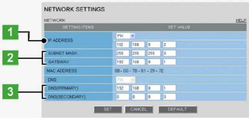
NETWORK SETTINGS NETWORK SETTING ITEMS SET VALUE IP ADDRESS FK 192 168 0 2 SUBNET MASK 255 255 255 0 GATEWAY 192 168 0 1 MAC ADDRESS 08-00-7B-81-29-7E DNS FK DNS(PRIMARY) 192 168 0 1 DNS(SECONDARY) 0 0 0 0 SET CANCEL DEFAULT1 In [IP ADDRESS], select "FIX" and type the IP address of the camera below it.
2 In [SUBNET MASK] and [GATEWAY], type your subnet mask and gateway addresses, respectively.
3 In [DNS (PRIMARY)] and [DNS (SECONDARY)], type your primary and secondary DNS server addresses and click SET.
Because you selected "FIX" in [IP ADDRESS], you specify here fixed DNS server addresses.
After completing the above steps, click the Close button to once disconnect and then reconnect to the camera to apply the changes.

To redo the procedure from the beginning, before clicking SET, click CANCEL.
To restore the factory default settings, click DEFAULT.
In [MAC ADDRESS], the MAC address of the camera is shown. You cannot change this address.
Automatic Configuration
text_image
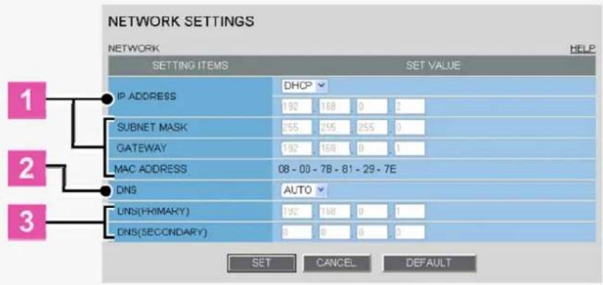
NETWORK SETTINGS NETWORK SETTING ITEMS SET VALUE IP ADDRESS DHCP 192 168 0 2 SUBNET MASK 255 255 255 0 GATEWAY 192 168 0 1 MAC ADDRESS 08 - 00 - 7B - 81 - 29 - 7E DNS AUTO LINS(FRIMARY) 192 168 0 1 DNS(SECONDARY) 0 0 0 0 SET CANCEL DEFAULT1 In [IP ADDRESS], select "DHCP".
The IP address, subnet mask, and gateway fields are automatically filled.
2 In [DNS], specify how you want to configure the DNS server addresses.
FIX: In [DNS (PRIMARY)] and [DNS (SECONDARY)] (3), type your primary and secondary DNS server addresses and click SET.
AUTO: Just click SET. Then, the system sets appropriate DNS server addresses automatically.
After completing the above steps, click the Close button to once disconnect and then reconnect to the camera to apply the changes.
B Configuring DDNS Settings
Using SANYO's DDNS service, you can connect to the camera from your Internet Explorer by simply entering the registered domain name, instead of the IP address of the camera.

To use the DDNS service, configure the following settings.
Specify your DNS server address under [DNS SETTINGS] on this screen.
Configure the port forwarding on your router. (For details, refer to your router's instruction manual.)
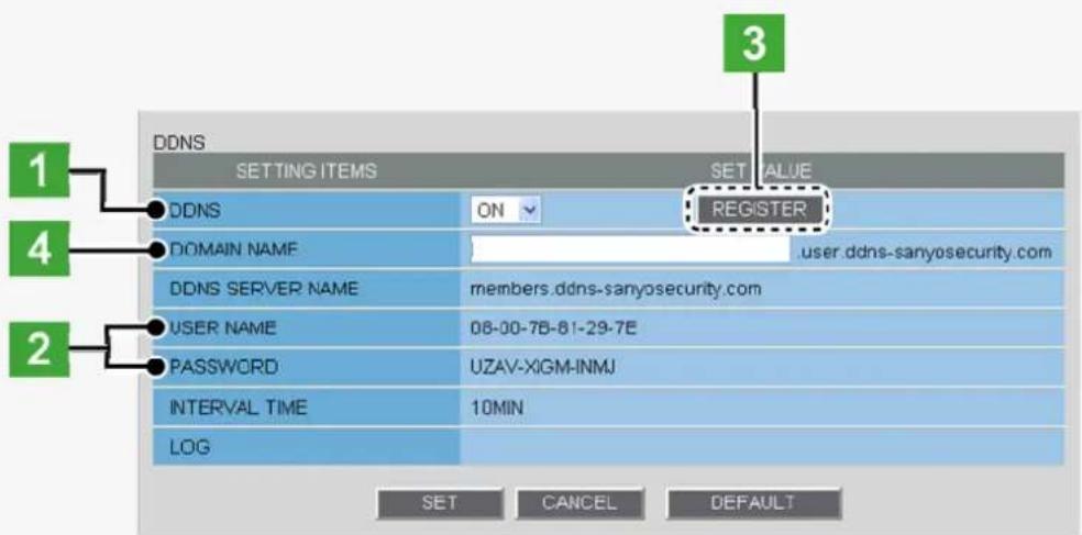
text_image
DDNS SETTING ITEMS SET VALUE 1 DDNS ON REGISTER 4 DOMAIN NAME user.ddns-sanyosecurity.com DDNS SERVER NAME members.ddns-sanyosecurity.com USER NAME 08-00-78-81-29-7E PASSWORD UZAV-XIGM-INMJ INTERVAL TIME 10MIN LOG SET CANCEL DEFAULT 31 In [DDNS], select "ON".
The [REGISTER] button (3) appears. The [USER NAME] and [PASSWORD] fields (2) show the automatically assigned user name and password, respectively.
2 Write down the user name and password shown in the [USER NAME] and [PASSWORD] fields.
This information is required to register your domain name.
3 Click REGISTER to access the SANYO DDNS service site and register your domain name.
Follow the steps below to register your domain name.
1 On the LOG IN screen, enter the user name and password you wrote down and click Login. The Domain Name registration/change screen appears.
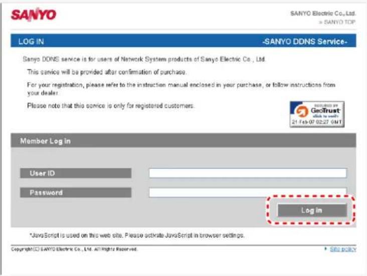
text_image
SANYO SANYO Electric Co., Ltd. > SANYO TOP LOG IN -SANYO DDNS Service- Sanyo DDNS service is for users of Network System products of Sanyo Electric Co., Ltd. This service will be provided after confirmation of purchase. For your registration, please refer to the instruction manual enclosed in your purchase, or follow instructions from your dealer. Please note that this service is only for registered customers. Member Log in User ID Password Login *JavaScript is used on this web site. Please activate JavaScript in browser settings. Copyright© SANYO Electric Co., Ltd. All Rights Reserved. Site policy
SANYO DDNS service site URL:
https://www.ddns-sanyosecurity.com
2 Enter the domain name you want to use and click Submit. The domain name is registered with the DDNS server.
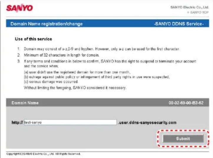
text_image
SANYO SANYO Electric Co., Ltd. + SANYO TCP Domain Name registration/change -SANYO DDNS Service- Use of this service 1. Domain may consist of a=2,0-9 and hyphen. However, only a=2 can be used for the first character. 2. Minimum of 32 characters in length for domain. 3. If any terms and conditions in below to confirm, SANYO has the right to suspend or terminate your account and the service when: (a) user didn't use the registered domain for more than one month, (b) outrage against public policy or infringement of third party rights in use were suspected, (c) serious damage was occurred. Without limiting the foregoing, SANYO considered it necessary. Domain Name 00-02-69-00-B3-B2 http://test-sanyo .user.ddns-sanyosecurity.com Submit Copyright©SANYO Electric Co., Ltd. All Rights Reserved.4 Return to the NETWORK SETTINGS screen ([DDNS]) and, in [DOMAIN NAME], type the domain name you just registered before “.user.ddns-sanyosecurity.com”. Then, click SET.

The [DDNS SERVER NAME] field is automatically filled ("members.ddns-sanyosecurity.com"), so you do not need to type it.
The [INTERVAL TIME] setting (access interval to the server) is fixed to "10" (10 minutes).
In the [LOG] field, the DDNS update history log (one entry) is shown.

Configuring HTTP settings
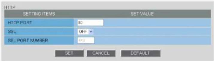
text_image
HTTP SETTING ITEMS SET VALUE HTTP PORT 80 SSL OFF SSL PORT NUMBER 443 SET CANCEL DEFAULT1 In [HTTP PORT], type your HTTP port number.
Type a number between 1 and 65535.

The default port number depends on whether or not you enable SSL communication in [SSL].
When [SSL] is set to "OFF": 80
When [SSL] is set to "ON": 443
2 To use SSL communication, select "ON" in [SSL], type your SSL port number in [SSL PORT NUMBER], and click SET.
Using SSL communication enables the encryption of image transmission.

SSL communication is effective for JPEG streaming images only.
When SSL communication is enabled, you will be presented with a security warning dialog box when attempting to access the camera. However, this is not a problem and you can continue the operation by clicking [Yes].
If the message "This page contains both secure and nonsecure items..." appears, follow the steps below to erase it.
1 In Internet Explorer, click [Internet Options] in the [Tool] menu.
2 On the [Security] tab, click the [Custom Level...] button.
3 In the [Security Settings] dialog box, in the [Settings] section, select the "Display mixed content" radio button.
When SSL communication is enabled, the frame rate of the live streaming images may become slower depending on the resolution setting.
Configuring RTSP/RTP settings
In [RTSP PORT], [RTP PORT (VIDEO)], and [RTP PORT (AUDIO)], type the desired port numbers and click SET.
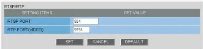
text_image
RTSP/RTP SETTING ITEMS SET VALUE RTSP PORT 554 RTP PORT(VIDEO) 5556 SET CANCEL DEFAULT
The RTSP port number must be 554 or otherwise a number in the range of 1 to 65535.
The RTP port (video and audio) numbers must be even numbers in the range of 1026 to 65534 (except for numbers between 3874 and 5000, between 9874 and 10000, between 38087 and 38214, and between 49026 and 49152).

Configuring Access Name Settings
If you intend to access the camera from video viewer or similar software, you may name each stream (access name) as you like for easy identification.
In [ACCESS NAME], type the access name (up to 32 alphanumeric characters) and click SET.
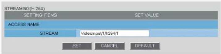
text_image
STREAMING(H.264) SETTING ITEMS SET VALUE ACCESS NAME STREAM VideoInput/1/h264/1 SET CANCEL DEFAULT
Access name works for H.264 video only.

Configuring Multicast settings
To enable multicast streaming, configure the multicast address, port numbers, and TTL for each stream, and click SET.
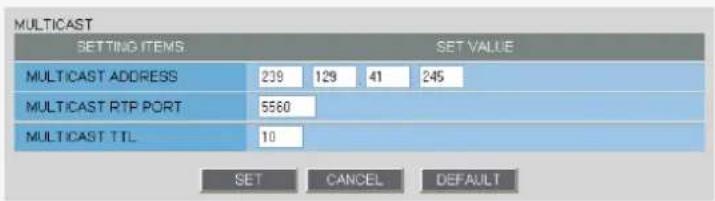
text_image
MULTICAST SETTING ITEMS SET VALUE MULTICAST ADDRESS 239 129 41 245 MULTICAST RTP PORT 5560 MULTICAST TTL 10 SET CANCEL DEFAULT
In [RTP PORT], specify an even number between 1026 and 65534. Make sure the specified number is not used as RTP unicast port number.
(except for numbers between 4000 and 5000, 10000, 10001, 38214, and 49152.)
The multicast TTL must be specified in the range of 1 to 255.
CLOCK SETTINGS
Click CLOCK in the configuration menu to display the CLOCK SETTINGS screen.
Before you start network operation, you need to configure the clock settings on this screen.
A Configuring camera title
B Configuring clock date/time and display style
Configuring time zone and daylight saving mode
D Configuring automatic clock adjustment

Required operation privilege: admin, operator
A Configuring camera title
Configure the camera title that will be displayed on the live screen and in e-mails, image files, and so on.

text_image
SETTING ITEMS TITLE Network Camera SET VALUEIn [TITLE], type the desired camera title and click SET.
You can type up to 16 alphanumeric characters.
The setting is saved and the camera title appears on the live screen.
![SANYO VCC-HD2100P - In [TITLE], type the desired camera title and click SET. - 1](/content/2026/05/817427/images/35c77374675279efd32a615c1fbd436ae40b9bebf5bb0cd29aa5ef0b8c4fa9fe.jpg)
Note that the camera title cannot include the following symbols: double quote ("), single quote ('), ampersand (&), greater-than sign (<), percent (%), backslash (), less-than sign (>), vertical bar (|), and semicolon (:).
A warning dialog box will appear when you click SET if the camera title includes any invalid character.
B Configuring clock date/time and display style
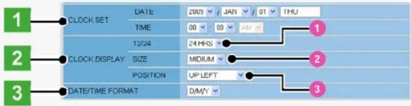
text_image
1 CLOCK SET DATE 2009 JAN 01 THU TIME 00 00 AM 12/24 24 HRS 2 CLOCK DISPLAY SIZE MEDIUM POSITION UP LEFT 3 DATE/TIME FORMAT D/M/Y1 In [CLOCK SET], configure the current date and time in [DATE] and [TIME], respectively.
The configured date and time settings will be reflected on the camera's built-in clock.
The day of the week is automatically set based on the date and time settings.
2 In [CLOCK DISPLAY], select the clock display style.
1 12/24 (Clock type): 12HRS (12-hour clock), 24HRS (24-hour clock)
2 SIZE (Character size): SMALL, MEDIUM, LARGE
3 POSITION (Display position): UP LEFT, UP RIGHT, DOWN LEFT, DOWN RIGHT, OFF (Hidden)
3 In [DATE/TIME FORMAT], select the date/time display format and click SET.
M/D/Y, Y/M/D, D/M/Y
![SANYO VCC-HD2100P - In [CLOCK DISPLAY], select the clock display style. - 1](/content/2026/05/817427/images/7b54f0321e7460a3bd9432ff330bbfc07deb6ad00389475e7e767373a1480e90.jpg)
Configuring time zone and daylight saving mode
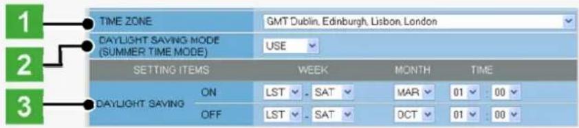
text_image
TIME ZONE GMT Dublin, Edinburgh, Lisbon, London DAYLIGHT SAVING MODE (SUMMER TIME MODE) USE SETTING ITEMS WEEK MONTH TIME ON LST - SAT MAR 01 : 00 DAYLIGHT SAVING OFF LST - SAT OCT 01 : 001 In [TIME ZONE], select the region where the camera is used.
2 In [DAYLIGHT SAVING MODE], select whether or not to use the daylight saving mode.
Although an appropriate setting is automatically selected according to the [TIME ZONE] setting, you can change it manually.
NO USE: Disables the daylight saving mode.
USE: Enables the daylight saving mode.
3 In [DAYLIGHT SAVING], select when to start (in [ON]) and end (in [OFF]) the daylight saving mode and click SET.
Although an appropriate setting is automatically selected according to the [TIME ZONE] setting, you can change it manually.

Configuring automatic clock adjustment
In [CLOCK ADJUST], select how you want to automatically adjust the camera's internal clock.
OFF: Disables the clock adjustment function.
ON (NTP): Enables automatic clock adjustment that retrieves the date and time information from the NTP server.
→ You need to configure the NTP settings.
LOGIN Enables automatic clock adjustment that retrieves the date and time information from the PC (PC): when an admin user logs into it.
ALARM Enables automatic clock adjustment that adjusts the clock to the specified time based on the signal received from the device connected to the ALARM IN1 terminal.
→ You need to configure the [CLOCK IN] setting.

It is recommended to select "ON (NTP)" when the camera is connected to the Internet.
If the camera is not connected to the Internet, select "LOGIN (PC)" or, using the supplied monitoring software "VA-SW3050Lite", enable the clock adjustment function (24-hour interval) in the clock setting.
Configuring NTP Settings
1 In [CLOCK ADJUST], select "ON (NTP)".
2 Configure the required settings shown below and click SET.
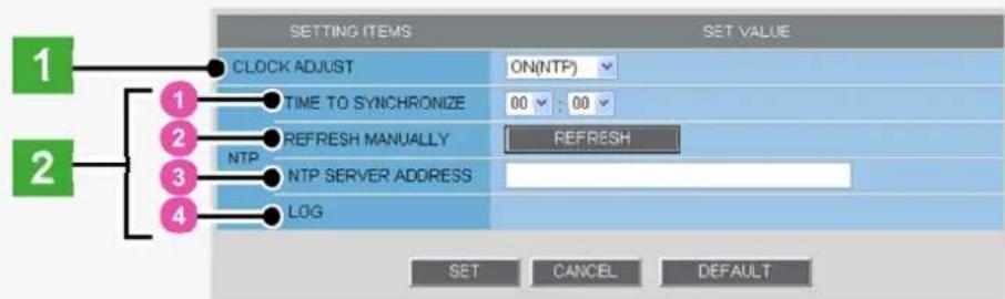
text_image
1 2 1 2 3 4 CLOCK ADJUST ON(NTP) TIME TO SYNCHRONIZE 00 : 00 REFRESH MANUALLY NTP NTP SERVER ADDRESS LOG SET CANCEL DEFAULT SET CANCEL DEFAULTTo automatically adjust the clock time every day, in [TIME TO SYNCHRONIZE], select the 24-hour time to which you want to adjust the clock (for example, "10:30").

2 To adjust the clock to the current time, click REFRESH.
3 In [NTP SERVER ADDRESS], type the IP address or domain name of the NTP server from which you want to retrieve the date and time information.
4 In [LOG], the last entry of the operation log related to automatic clock adjustment is shown.

When "ON (NTP)" in [CLOCK ADJUST] is selected, the clock adjustment function adjusts the clock in the following timings.
When the camera is turned on At the time selected in [TIME TO SYNCHRONIZE] (every day) When any change is made to the settings on this screen
To use a domain name, you must specify the DNS server address in [DNS SERVER ADDRESS] on the NETWORK SETTINGS screen.
Configuring CLOCK IN Setting
1 In [CLOCK ADJUST], select "ALARM IN1".
2 In [CLOCK IN], select the 24-hour time to which you want to adjust the clock (for example, “22” for 10 p.m.) when the switch connected to the ALARM IN1 terminal turns on, and click SET.
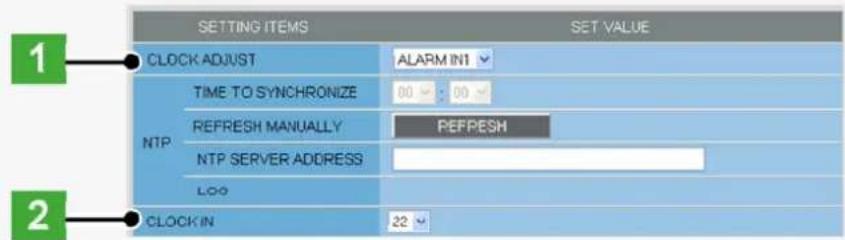
text_image
SETTING ITEMS SET VALUE 1 CLOCK ADJUST ALARM IN1 TIME TO SYNCHRONIZE 00 00 NTP REFRESH MANUALLY REFRESH NTP SERVER ADDRESS LOG 2 CLOCK IN 22The clock time will not be adjusted if the difference between the set time and the current time exceeds the range of -29 to +30 minutes.
If you set [CLOCK ADJUST] to "ALARM IN1", the ALARM IN1 terminal will serve dedicatedly as a time adjustment terminal, so you can see only the item [POLARITY] in [ALARM IN1] on the ALARM SETTINGS screen.
USER SETTINGS
Click USER in the configuration menu to display the USER SETTINGS screen.
On this screen, configure the user authentication check at login.

Required operation privilege: admin, operator

Disabling authentication check
Disabling the authentication check at login allows all users to log into the camera without authentication.
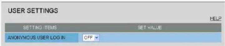
text_image
USER SETTINGS HELP SETTING ITEMS SET VALUE ANONYMOUS USER LOG IN OFFIn [ANONYMOUS USER LOG IN], select "ON" and click SET.
![SANYO VCC-HD2100P - In [ANONYMOUS USER LOG IN], select "ON" and click SET. - 1](/content/2026/05/817427/images/cefaa09ac83dae1ab94bb889ac90b51b0753acf3fccf47450491305f970d42cb.jpg)
In this case, all login users are regarded as guest users.
This means that users will be presented with an authentication check dialog box if they attempt to perform any operation beyond the guest user privilege and must enter an adequate user name and password to proceed.
![SANYO VCC-HD2100P - In [ANONYMOUS USER LOG IN], select "ON" and click SET. - 2](/content/2026/05/817427/images/ccc6be15a887e465cf5272cf45f5b9ec4a698e52556d81e559fef0b3da06b8e9.jpg)
Changing your password
Change your login user password (4 to 32 alphanumeric characters).
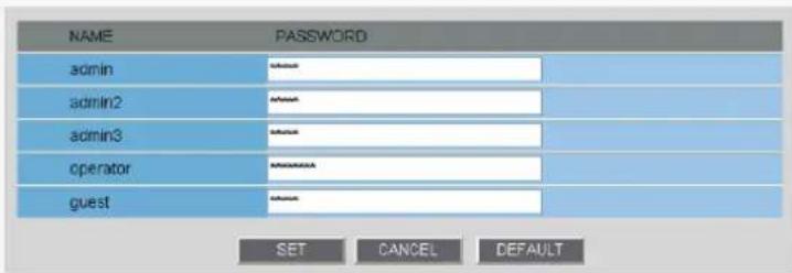
text_image
NAME PASSWORD admin admin2 admin3 operator guest SET CANCEL DEFAULTIn [PASSWORD], type the new password for the relevant user and click SET.
![SANYO VCC-HD2100P - In [PASSWORD], type the new password for the relevant user and click SET. - 1](/content/2026/05/817427/images/590b67ffe3a7a7f71277692f8480d004f9aa8cd6b45853ea73c28586cce275dd.jpg)
Update your password periodically for security reasons.
To restore the default user passwords, click DEFAULT.
CODEC/STREAMING SETTINGS
Click CODEC/STREAMING in the configuration menu to display the CODEC/STREAMING SETTINGS screen.
Configure the conditions of the video/image transmission.
A Configuring Aspect Ratio
B Configuring JPEG images
Configuring H.264 video

Required operation privilege: admin, operator
If [SSL] is set to "ON" on the NETWORK SETTINGS screen, you cannot configure H.264 video.
A Configuring Aspect Ratio

text_image
CODEC / STREAMING SETTINGS ASPECT RATIO SETTING ITEMS SET VALUE ASPECT RATIO 16.9 HELPIn [ASPECT RATIO], select the aspect ratio (width-to-height ratio) of the video/image by clicking the corresponding radio button and click SET.
16:9 (Landscape), 4:3 (Portrait)

Clicking SET reboots the camera.
B Configuring JPEG images
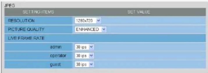
text_image
JPEG SETTING ITEMS SET VALUE RESOLUTION 1280x720 PICTURE QUALITY ENHANCED LIVE FRAME RATE admin 30 ips operator 30 ips guest 30 ips1 Configure the resolution (RESOLUTION).
The available options vary depending on your selection in [ASPECT RATIO].
16:9: 1920×1080, 1280×720, 1024×576, 640×360
4:3: 2288×1712, 1600×1200, 1280×960, 1024×768, 800×600, 640×480, 320×240
2 Configure the image quality (PICTURE QUALITY).
BASIC, NORMAL, ENHANCED, FINE, SUPER FINE
3 Configure the live video frame rate (LIVE FRAME RATE) for each operation privilege and click SET.
The available options vary depending on the model used.
VCC-HD2300/VCC-HD2100: 0.1ips, 0.2ips, 0.5ips, 1ips, 3ips, 5ips, 10ips, 15ips, 30ips
VCC-HD2300P/VCC-HD2100P: 0.1ips, 0.2ips, 0.5ips, 1ips, 2.5ips, 5ips, 8ips, 12.5ips, 25ips

Configuring H.264 video
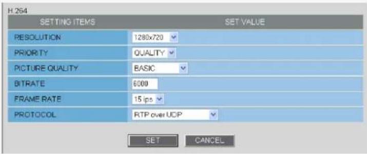
text_image
H.264 SETTING ITEMS SET VALUE RESOLUTION 1280x720 PRIORITY QUALITY PICTURE QUALITY BASIC BITRATE 6000 FRAME RATE 15 fps PROTOCOL RTP over UDP SET CANCEL1 Configure the resolution (RESOLUTION).
The available options vary depending on your selection in [ASPECT RATIO].
16:9: 1920×1080, 1280×720, 640×360, 320×180
4:3: 1600×1200, 1280×960, 1024×768, 640×480, 320×240
2 In [PRIORITY], select whether you put priority on the video/image quality or the bit rate.
QUALITY, BITRATE
When your selection in [PRIORITY] is "QUALITY" (PICTURE QUALITY)
Then, the system shows an appropriate bit rate depending on the selected quality.
BASIC, NORMAL, ENHANCED, FINE, SUPER FINE
When your selection in [PRIORITY] is "BITRATE" (BITRATE)
Type the bit rate directly, if you want to change it.
3 In [FRAME RATE], select the frame rate of the stream.
The available options vary depending on the model used.
VCC-HD2300/VCC-HD2100: 15ips, 30ips
VCC-HD2300P/VCC-HD2100P: 12.5ips, 25ips
![SANYO VCC-HD2100P - In [FRAME RATE], select the frame rate of the stream. - 1](/content/2026/05/817427/images/70e29db3e75d375b06d5efa0f707e3bdea4e37e58e40cc7d60be0d46d64e947b.jpg)
Depending on the configured resolution, the available options for image quality and frame rate may be limited.
4 Select the H.264 video streaming method (PROTOCOL) and click SET .
UDP (Unicast), RTSP, HTTP, MULTICAST
CAMERA SETTINGS
Click CAMERA in the configuration menu to display the CAMERA SETTINGS screen.
The CAMERA SETTINGS screen includes a sub menu from which you can access 14 camera settings to configure the monitoring and other conditions of the camera.

Required operation privilege: admin, operator
Function of Each Screen Component
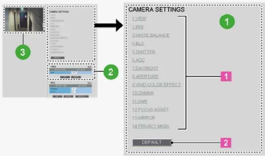
flowchart
graph TD
    A["Camera Settings"] --> B["1 VIEW"]
    A --> C["2 JBS"]
    A --> D["3 WHITE BALANCE"]
    A --> E["4 PLC"]
    A --> F["5 SHUTTER"]
    A --> G["6 AGC"]
    A --> H["7 DAY/NIGHT"]
    A --> I["8 APERTURE"]
    A --> J["9 VMID, COLOR EFFECT"]
    A --> K["10 GAMMA"]
    A --> L["11 CNR"]
    A --> M["12 FOCUS ASSIST"]
    A --> N["13 MRRGR"]
    A --> O["14 PRIVACY MASK"]
    P["CAMERA Settings"] --> Q["1"]
    Q --> R["2"]
    R --> S["DEFAULT"]
1 Sub Menu List
The CAMERA SETTINGS sub menu offers a list of camera settings.
| 1 Sub menu: | Click one of the menu items in the sub menu to jump to the desired camera settings. |
| 2 DEFAULT : | Click this button to reset all the settings you configured for the selected view (CAM1/CAM2) to the defaults (factory settings). |
2 Configuration Section
This area shows a series of camera settings. You can use the vertical scroll bar and scroll buttons to scroll the settings up and down.
For each camera setting configuration section, the following buttons are provided.
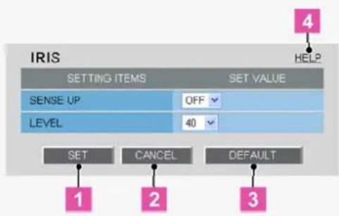
text_image
IRIS SETTING ITEMS SET VALUE SENSE UP OFF LEVEL 40 SET CANCEL DEFAULT 1 2 3 4 HELP| 1 SET : | Click this button when finished configuring the camera settings you accessed by clicking each sub menu item. |
| 2 CANCEL : | Click this button before clicking SET to restore the previous settings. |
| 3 DEFAULT : | Click this button to reset the settings on the camera configuration screen to the defaults (factory settings). |
| 4 HELP: | Click this to display a menu from which you can display the explanation of each configuration screen on the HELP screen. |
Configuration Summary for Each Sub Menu Item
| Sub Menu Operation Application | |||
| 1 | VIEW You can have two patterns of view settings (CAM1/CAM2) by configuring the monitoring conditions through sub menu items “2 IRIS” to “11 PRIVACY MASK”. | VIEW | |
| 2 | IRIS Configure the lens iris. VIEW | ||
| 3 | WHITE BALANCE | Adjust the white balance. VIEW | |
| 4 | BLC | Configure the backlight compensation function. | VIEW |
| 5 | SHUTTER | Configure the electronic shutter. | VIEW |
| 6 | AGC | Configure the gain of the video signal. | VIEW |
| 7 | DAY/NIGHT | Configure the Day/Night function that automatically switches the camera between color and black-and-white video modes depending on the luminance of the target.(This function is supported only by VCC-HD2300P/VCC-HD2300) | VIEW |
| 8 | APERTURE | Configure the contour compensation function. | VIEW |
| 9 | VIVID COLOR EFFECT | Configure the color saturation compensation function. | VIEW |
| 10 | GAMMA | Configure the gamma correction level. | VIEW |
| 11 | DNR | Configure the noise reduction function. | VIEW |
| 12 | FOCUS ASSIST | Configure the focus assist function to adjust the focus. | Common |
| 13 | MIRROR | Configure the mirror function to flip the subject on the monitor. | Common |
| 14 | PRIVACY MASK | Configure the privacy mask settings to mask portions of the subject you want to hide for privacy protection. | Common |

"Application" in the above table means the following:
VIEW: The configured settings will be applied to "CAM1" or "CAM2", whichever you selected under [VIEW].
Common: The configured settings will be applied commonly to "CAM1" and "CAM2" selected under [VIEW].
3 Live Image Display Area
You can view how your changes affect the video image in real time.
VIEW
You can configure two patterns of monitoring conditions.
For example, select "CAM1" to configure the normal live monitoring conditions for daytime use and select "CAM2" to configure the monitoring conditions with the Day/Night function for nighttime use, respectively. Thus, you can switch the monitoring conditions depending on your needs.
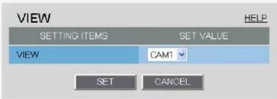
text_image
VIEW SETTING ITEMS SET VALUE VIEW CAM1 SET CANCEL HELPConfiguring Monitoring Conditions
In [VIEW], select "CAM1" or "CAM2" and then configure the monitoring conditions by clicking each menu item in the sub menu.
Switching between Monitoring Conditions
In [VIEW], select "CAM1" or "CAM2". The monitoring conditions configured for the selected view setting are now applied to the camera.
IRIS
Configure the lens iris according to the brightness of the subject displayed on the screen.

The configured settings will be applied to "CAM1" or "CAM2", whichever you selected under [VIEW].
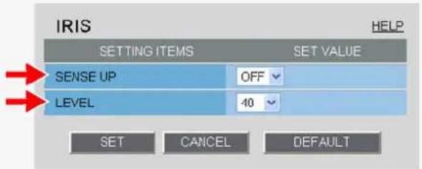
text_image
IRIS SETTING ITEMS SET VALUE SENSE UP OFF LEVEL 40 SET CANCEL DEFAULT HELP1 In [SENSE UP], select the electronic sensitivity boosting power.
OFF, x2, x4, x8, x16, x32
![SANYO VCC-HD2100P - In [SENSE UP], select the electronic sensitivity boosting power. - 1](/content/2026/05/817427/images/183b67bc9686e732f0fdd2dfee79e0fe53015875d90fe70c1acac558767f22aa.jpg)
Enabling the electronic sensitivity boosting function causes the following:
The exposure time of the camera's image sensing device will be increased automatically in dark situations. This may result in conspicuous afterimages, blurs, and white spots if the subject includes any moving object.
If [DAY/NIGHT] is set to "AUTO", the electronic sensitivity boosting function will work only for black/white video images. (For VCC-HD2300P/VCC-HD2300)
[SHUTTER] is set to "OFF", preventing you from configuring the electronic shutter setting ("SHORT" or "LONG").
No motion sensor type can be selected in [MOTION] on the ALARM SETTINGS screen.
You cannot configure the electronic sensitivity boosting function in the following case:
When [AGC] is set to "OFF".
A motion sensor type is selected in [MOTION] on the ALARM SETTINGS screen.
2 In [LEVEL], select the video signal level and click SET.
0 (dark) to 100 (bright)
WHITE BALANCE
Select and configure the white balance adjustment mode.
ATW: Auto trace white balance
AWC: Auto white balance control
3200: Fixed white balance (for indoors)
5600: Fixed white balance (for outdoors)
FLUORESCENT: Fixed white balance (for fluorescent lighting)
MWB: Manual white balance

The configured settings will be applied to "CAM1" or "CAM2", whichever you selected under [VIEW].
Configuring the Auto Trace White Balance Mode (ATW)
Auto trace white balance (ATW) automatically adjusts the white balance to provide optimal colors, even if the light source for the target object is changed.
Enable the smart ATW function here because ATW may not produce desirable results if a single solid color occupies a large part of the subject.
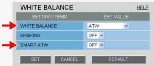
text_image
WHITE BALANCE SETTING ITEMS SET VALUE WHITE BALANCE ATW MASKING OFF SMART ATW OFF SET CANCEL DEFAULT HELP1 In [WHITE BALANCE], select "ATW".
2 In [SMART ATW], select "ON" and click SET.
The camera now adjusts the white balance automatically based on the color information on the subject.

Do not use the smart ATW function in environments where the color temperature fluctuates. In an outdoor environment for example, smart ATW may not produce desirable results because the color temperature fluctuates depending on the time of the day (at sunrise, daytime, and sunset), weather (sunny or cloudy), and other conditions.
If Subject Includes an Extremely Bright Light Source
1 In [MASKING], select "ON" and click SET.
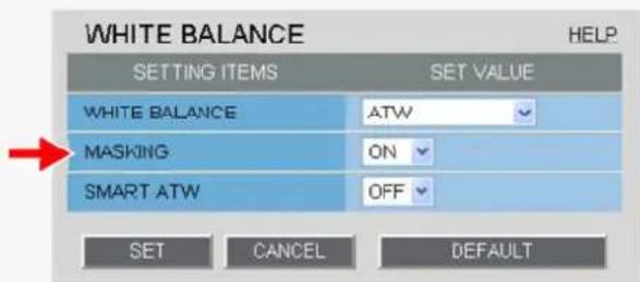
text_image
WHITE BALANCE SETTING ITEMS SET VALUE WHITE BALANCE ATW MASKING ON SMART ATW OFF SET CANCEL DEFAULTThe ATW masking screen appears.
Mask the light source by the following procedure.
2 Drag the mouse over the live video image to select the area you want to mask.
The masked area is indicated by blue-bordered grid cells each containing the letter "M". You can mask more than one portion of the live image.
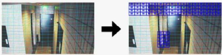
natural_image
Two-panel image showing a hallway with tiled walls and a grid of blue square overlays on the right side (no text or symbols)
You can click one grid cell after another to set or cancel the masked area cell by cell.
To deselect a block of grid cells in the masked area, right-click one of grid cell and drag the mouse.
3 Click SET and then BACK.
The settings are saved and you return to the sub menu.
Configuring Auto White Balance Control Mode (AWC)
Use AWC if auto trace white balance (ATW) does not reproduce a natural white balance.
AWC allows you to automatically adjust the white balance by simply clicking SET with the camera lens directed toward a white wall, white paper and the like.
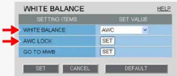
text_image
WHITE BALANCE SETTING ITEMS SET VALUE WHITE BALANCE AWC AWC LOCK SET GO TO MWB SET SET CANCEL DEFAULT HELP1 In [WHITE BALANCE], select "AWC".
2 Direct the camera lens toward a white wall, white paper and the like and, in [AWC LOCK], click SET.
If the white balance adjustment does not reproduce desirable results, click SET again.
You need to follow the above steps also to re-adjust the white balance when the lighting conditions have been changed.

To fine-tune the white balance after this adjustment, in [GO TO MWB], click SET.
Configuring Fixed White Balance Mode (3200/5600/FLUORESCENT)
You can set the color temperature to a fixed value.
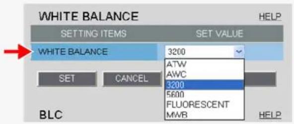
text_image
WHITE BALANCE SETTING ITEMS SET VALUE WHITE BALANCE 3200 ATW AWC 3200 5600 FLUORESCENT MWB BLC HELPIn [WHITE BALANCE], select the desired fixed white balance mode and click SET.
3200: For indoors (Fixes the color temperature to 3200K.)
5600: For outdoors (Fixes the color temperature to 5600K.)
FLUORESCENT: For fluorescent lighting (Fixes the color temperature to 4200K.)
Configuring the Manual White Balance Mode (MWB)
Use the following procedure to manually adjust the gain values for the red and blue signals.
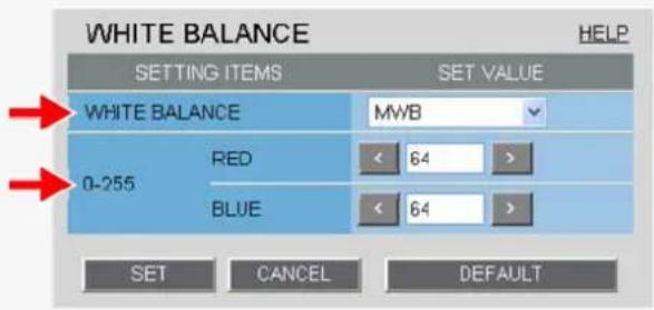
text_image
WHITE BALANCE SETTING ITEMS SET VALUE WHITE BALANCE MWB 0-255 RED 64 > BLUE 64 > SET CANCEL DEFAULT HELP1 In [WHITE BALANCE], select "MWB".
2 In [RED] and [BLUE], specify the gain values for the red and blue signals, respectively, and click SET.
RED: 0 (light) to 255 (dark)
BLUE: 0 (light) to 255 (dark)
BLC
You can use the backlight compensation (BLC) function to make the subject easily visible under strong backlight conditions.
OFF: Disables the backlight compensation function.
MULTI: Selects the multi-spot evaluative metering mode.
CENTER: Selects the center-weighted evaluative metering mode.
MASKING: Selects the light source masking mode.

The configured settings will be applied to "CAM1" or "CAM2", whichever you selected under [VIEW].
Configuring Multi-Spot Evaluative Metering Mode (MULTI)
Multi-spot evaluative metering compensates for the backlighting problem by evaluating the photometry of the entire screen.
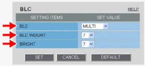
text_image
BLC SETTING ITEMS SET VALUE BLC MULTI BLC WEIGHT 7 BRIGHT 7 SET CANCEL DEFAULT HELP1 In [BLC], select "MULTI".
2 In [BLC WEIGHT], select the backlight sensitivity.
0 (low sensitivity) to 15 (high sensitivity)
3 In [BRIGHT], select the compensation level for the brightness of the backlighting and click SET.
0 (low brightness compensation) to 15 (high brightness compensation)
Configuring Center-Weighted Average Metering Mode (CENTER)
Center-weighted average metering compensates for the backlighting problem by measuring the photometry of the specified area intensively.
Configure the position and size of the center metering area.
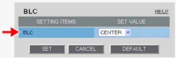
text_image
BLC SETTING ITEMS SET VALUE BLC CENTER SET CANCEL DEFAULT HELP1 In [BLC], select "CENTER" and click SET.
The BLC center/window weighting setting screen appears, showing a rectangle representing the center metering area in the center of the screen.
2 Drag the rectangle to set the center metering area in position.
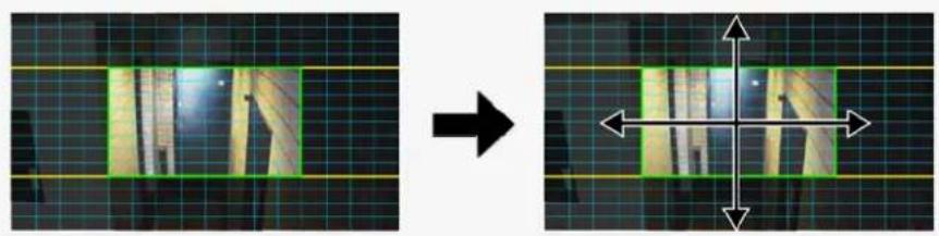
natural_image
Two-panel image showing a grid with vertical light patterns on the left and a crosshair overlay on the right (no text or symbols)
Center-weighted average metering may not be set depending on the position of the center metering area.
3 Resize the center metering area.
To resize the center metering area, place the mouse pointer over the border of the area and then drag it.
4 Configure the metering weight values for the four surrounding metering areas (TOP, BOTTOM, LEFT, and RIGHT).
Select a weight value for each of these metering areas depending on the installation environment.
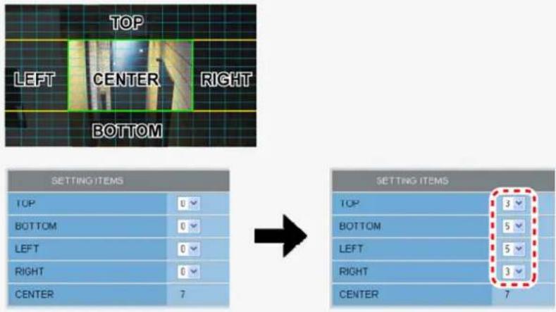
text_image
TOP LEFT CENTER RIGHT BOTTOM SETTING ITEMS TOP 0 BOTTOM 0 LEFT 0 RIGHT 0 CENTER 7 SETTING ITEMS TOP 3 BOTTOM 5 LEFT 5 RIGHT 3 CENTER 70 (minimum) to 7 (maximum)

The weight value for the center metering area ([CENTER]) is fixed to "7". You cannot change this value.
The brightness value represents the weight for each area and therefore does not affect the actual live video image from the camera.
5 Click SET and then BACK.
The settings are saved and you return to the sub menu.
Configuring Light Source Masking Mode (MASKING)
You can use light source masking to compensate for backlighting problems with human or other objects in the subject, by masking the light source in a bright background.
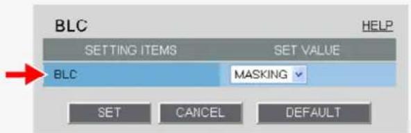
text_image
BLC SETTING ITEMS SET VALUE BLC MASKING SET CANCEL DEFAULT HELP1 In [BLC], select "MASKING" and click SET.
The BLC masking screen appears.
2 Drag the mouse over the live video image to select the area you want to mask.
The masked area is indicated by blue-bordered grid cells each containing the letter "M".
You can mask more than one portion of the live image.
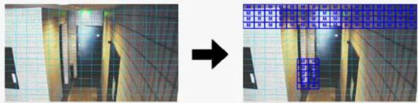
natural_image
Two-panel image showing a hallway with tiled walls and a grid of blue square tiles on the right (no text or symbols)
You can click one grid cell after another to set or cancel the masked area cell by cell.
To deselect a block of grid cells in the masked area, right-click one of grid cell and drag the mouse.
3 Click SET and then BACK.
The settings are saved and you return to the sub menu.
SHUTTER
Configure the electronic shutter or electronic iris settings according to the movement and luminance level of the subject.
OFF: Disables the electronic shutter or electronic iris function.
SHORT: Enables the fast shutter mode.
LONG: Enables the long exposure shutter mode.
EI: Electronic iris

The configured settings will be applied to "CAM1" or "CAM2", whichever you selected under [VIEW].
Configuring Fast Shutter Mode (SHORT)
The fast shutter mode has a shorter exposure time than the field storage time.
Configuring the fast shutter mode enables you to capture quick motion in the subject.

You cannot select "SHORT" to configure the fast shutter mode if the electronic sensitivity boosting ([SENSE UP] in [IRIS]) is enabled.
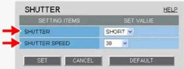
text_image
SHUTTER SETTING ITEMS SET VALUE SHUTTER SHORT SHUTTER SPEED 30 SET CANCEL DEFAULT HELP1 In [SHUTTER], select "SHORT".
2 In [SHUTTER SPEED], select the desired shutter speed and click SET.
The available options vary depending on the model used.
VCC-HD2300P/VCC-HD2100P: 25, 50, 120, 250, 500, 1000, 2000, 4000, 10000
VCC-HD2300/VCC- HD2100 : 30, 60, 100, 250, 500, 1000, 2000, 4000, 10000
![SANYO VCC-HD2100P - In [SHUTTER SPEED], select the desired shutter speed and click SET. - 1](/content/2026/05/817427/images/177003d91d8488c50d1b7f91d0debbc83c1b32de7502f82717c335ff154c6419.jpg)
Each of the above shutter speed values represents the denominator "n" of the fraction 1/n. For example, selecting "500" means to set a shutter speed of 1/500 second.
Configuring Long Exposure Shutter Mode (LONG)
The long exposure shutter mode has a longer exposure time than the field storage time.
The long exposure shutter mode increases the sensitivity of the camera to make the subject brighter.

You cannot select "LONG" to configure the long exposure shutter mode if the electronic sensitivity boosting ([SENSE UP] in [IRIS]) is enabled.
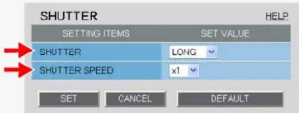
text_image
SHUTTER SETTING ITEMS SET VALUE SHUTTER LONG SHUTTER SPEED x1 SET CANCEL DEFAULT HELP1 In [SHUTTER], select "LONG".
2 In [SHUTTER SPEED], select the desired shutter speed and click SET.
x1, x2, x4, x8, x16, x32

Each of the above shutter speed values represents a multiple of the field storage time. The higher the value, the longer the exposure time.

Setting an excessively long exposure time may result in ghosts, blurs and white spots if the subject includes any moving object.
Configuring Electronic Iris Mode (EI)
The electronic iris controls both the AGC and the shutter speed to adjust the exposure.
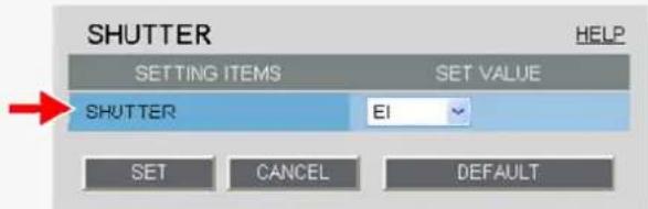
text_image
SHUTTER SETTING ITEMS SET VALUE SHUTTER EI SET CANCEL DEFAULT HELPIn [SHUTTER], select "EI" and click SET.

If you are using an auto iris lens, the electronic iris will activate automatically at the open end of the aperture to adjust the exposure even when [SHUTTER] is set to "OFF".
AGC
Configure the video signal gain value automatically or manually.
Automatically configuring gain value using AGC
Manually configuring gain value

Auto Gain Control (AGC) is a function that automatically adjusts the gain value of the camera's video signal amplifying circuit according to the brightness of the subject to maintain a constant signal output.
The configured settings will be applied to "CAM1" or "CAM2", whichever you selected under [VIEW].
Automatically configuring gain value using AGC
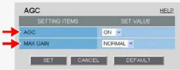
text_image
AGC SETTING ITEMS SET VALUE AGC ON MAX GAIN NORMAL SET CANCEL DEFAULT HELP1 In [AGC], select "ON".
2 In [MAX GAIN], select the maximum gain level for AGC and click SET.
Selecting a higher gain level will improve the camera sensitivity in a dark condition, but increase the noise as well.
NORMAL: For normal subject
MIDDLE: For slightly dark subject
HIGH: For dark subject

The maximum gain value varies depending on the mode set for [DAY/NIGHT]. (For VCC-HD2300P/VCC-HD2300)
Manually configuring gain value
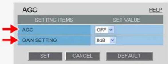
text_image
AGC HELP SETTING ITEMS SET VALUE AGC OFF GAIN SETTING 0dB SET CANCEL DEFAULT
If you set [AGC] to "OFF", you cannot enable the electronic sensitivity boosting function (in [SENSE UP] in [IRIS]).
You cannot select "OFF" in [AGC] if [DAY/NIGHT] is set to "AUTO" or the electronic sensitivity boosting ([SENSE UP]) is enabled. (For VCC-HD2300P/VCC-HD2300)
1 In [AGC], select "OFF".
2 In [GAIN SETTING], select the gain value of AGC and click SET.
0dB, 3dB, 6dB, 9dB, 12dB, 15dB, 18dB, 21dB, 24dB, 27dB, 30dB, 33dB, 36dB, 39dB, 42dB
DAY/NIGHT
The Day/Night function improves the camera's sensitivity by automatically switching the camera to the color mode in bright conditions and to the black-and-white mode in dark situations.
Using this function enables 24-hour surveillance with clear video images even during nighttime or in dark locations.
You may also fix the camera to the color or black-and-white video mode without using the Day/Night function.
Automatically switching camera between color and black-and-white video modes using Day/Night function
Switching camera between color and black-and-white video modes when an external control signal is received
Fixing camera to color or black-and-white video mode

This function is supported only by VCC-HD2300P/VCC-HD2300.

The configured settings will be applied to "CAM1" or "CAM2", whichever you selected under [VIEW]. In AUTO mode, turning off the camera in the black-and-white mode and then turning it back on again switches it to the color mode.
The focused position may differ between the color and black-and-white modes.
When using infrared lighting in the black-and-white mode, the camera may switch to the color mode due to strong reflection from objects in the subject. In this case, adjust the infrared lighting to prevent the switching of video to the color mode.
Automatically Switching Camera between Color and Black-and-White Video Modes
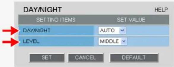
text_image
DAY/NIGHT HELP SETTING ITEMS SET VALUE DAY/NIGHT AUTO LEVEL MIDDLE SET CANCEL DEFAULT1 In [DAY/NIGHT], select "AUTO".
![SANYO VCC-HD2100P - In [DAY/NIGHT], select "AUTO". - 1](/content/2026/05/817427/images/e38f5b7b9f1525ec7ceaec761df883c4d2942df567038ba53f90181be2cd516f.jpg)
If you select "AUTO", you cannot set [AGC] to "OFF".
2 In [LEVEL], select the luminance level at which the video mode is switched and click SET.
HIGH: Sets a high luminance level (to increase the time during which the camera operates in the black-and-white mode).
MIDDLE: Sets the luminance level to halfway between "LOW" and "HIGH".
LOW: Sets a low luminance level (to increase the time during which the camera operates in the color mode).
ADJ: Enables the manual adjustment of the luminance level.
Manually Configuring Mode-Switching Luminance Level (ADJ)
You can select a luminance level between 1 and 7 for both the color to black-and-white switching and black-and-white to color switching. Switching occurs in darker conditions as the luminance level increases.
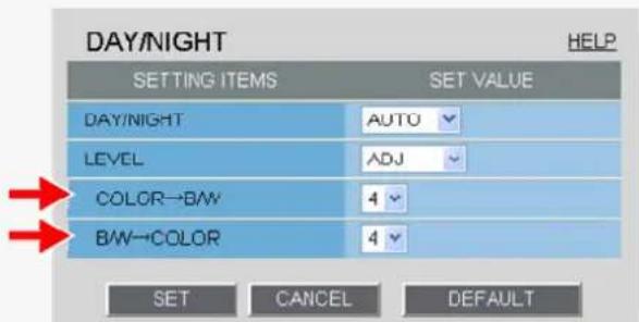
text_image
DAY/NIGHT HELP SETTING ITEMS SET VALUE DAY/NIGHT AUTO LEVEL ADJ COLOR→BW 4 BW→COLOR 4 SET CANCEL DEFAULTCOLOR→B/W
Select the luminance level at which switching occurs from the color mode to the black-and-white mode.
B/W→COLOR
Select the luminance level at which switching occurs from the black-and-white mode to the color mode.

Changing one of these settings also changes the other setting based on the difference.
To prevent hunting in infrared (IR) lighting, set these luminance levels to widely different values.
Switching camera between color and black-and-white video modes when an external control signal is received
Using one of these alarm input terminals as the Day/Night switching terminal, however, enables the camera to be switched between the color and black-and-white video modes when an external control signal is received.
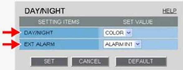
text_image
DAY/NIGHT HELP SETTING ITEMS SET VALUE DAY/NIGHT COLOR EXT ALARM ALARM IN1 SET CANCEL DEFAULT1 In [DAY/NIGHT], select "COLOR".
2 In [EXT ALARM], select the desired alarm input terminal and click SET.
ALARM IN1: Sets the ALARM IN1 terminal as the Day/Night switching terminal.
ALARM IN2: Sets the ALARM IN2 terminal as the Day/Night switching terminal.
OFF: Fixing Camera to Color Video Mode

You need to enable the ALARM IN1/2 terminal and configure the signal polarity in [POLARITY] on the ALARM SETTINGS screen.
Depending on the [POLARITY] setting, the camera will be switched between the color and black-and-white video modes as follows (commonly applied to CAM1 and CAM2):
If [POLARITY] is set to "NO": Color mode when open; Black-and-white mode when closed
If [POLARITY] is set to "NC": Color mode when closed; Black-and-white mode when open
If you set [EXT ALARM] to "ALARM IN1" or "ALARM IN2", the corresponding alarm input terminal will serve dedicatedly as a Day/Night switching terminal, so you can see only the item [POLARITY] on the ALARM SETTINGS screen.
Fixing camera to color or black-and-white video mode
Fixing Camera to Color Video Mode
In [DAY/NIGHT] and [EXT ALARM], select "COLOR" and "OFF", respectively, and click SET.
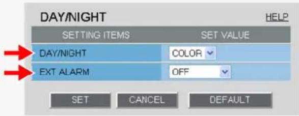
text_image
DAY/NIGHT SETTING ITEMS SET VALUE DAY/NIGHT COLOR EXT ALARM OFF SET CANCEL DEFAULT HELPFixing Camera to Black-and-White Video Mode
In [DAY/NIGHT], select "B/W" and click SET.
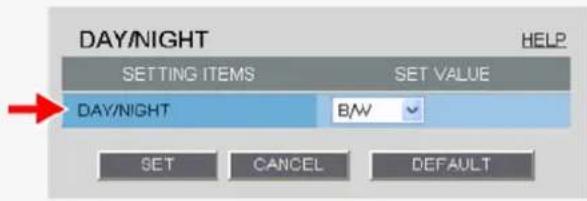
text_image
DAY/NIGHT SETTING ITEMS SET VALUE DAY/NIGHT B/W SET CANCEL DEFAULT HELPAPERTURE
You can use the contour compensation function to make the whole video image clearer.
Select "ON" in [APERTURE] and an appropriate correction level in [LEVEL] and click SET.
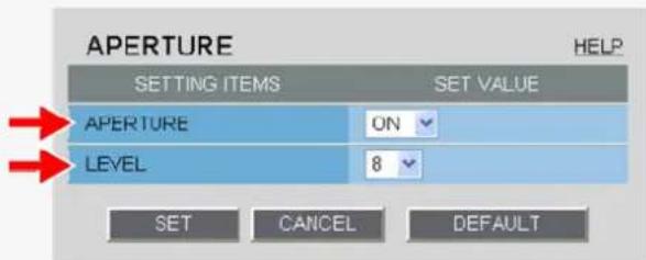
text_image
APERTURE HELP SETTING ITEMS SET VALUE APERTURE ON LEVEL 8 SET CANCEL DEFAULTThe higher the correction level, the greater the correction effect.
1 to 15

The configured settings will be applied to "CAM1" or "CAM2", whichever you selected under [VIEW].
VIVID COLOR EFFECT
Use the color saturation compensation function to improve the vividness of the color.
In [VIVID COLOR EFFECT], select "ON" and click SET.
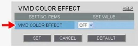
text_image
VIVID COLOR EFFECT HELP SETTING ITEMS SET VALUE VIVD COLOR EFFECT OFF SET CANCEL DEFAULT
The configured settings will be applied to "CAM1" or "CAM2", whichever you selected under [VIEW].
GAMMA
Set the gamma correction level to adjust the contrast or brightness level.
In [GAMMA], select the gamma correction level and click SET.
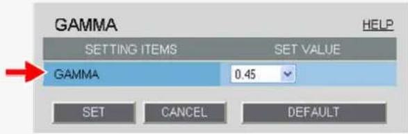
text_image
GAMMA SETTING ITEMS SET VALUE GAMMA 0.45 SET CANCEL DEFAULT HELP0.45: Gamma correction level = 0.45
1: Gamma correction level = 1
MODE1: Increases the contrast of the whole subject.
MODE2: Increases the contrast in dark areas further.

The configured settings will be applied to "CAM1" or "CAM2", whichever you selected under [VIEW]. Selecting "MODE1" or "MODE2" may result in excessively bright images depending on the target object.
DNR
Configure the DNR (Digital Noise Reduction) function to reduce noise at low conditions.
In [DNR], select "ON" and click SET.
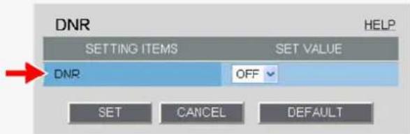
text_image
DNR SETTING ITEMS SET VALUE DNP OFF SET CANCEL DEFAULT HELP
The configured settings will be applied to "CAM1" or "CAM2", whichever you selected under [VIEW]. Enabling the DNR function may cause ghosts and blurs if the subject includes any moving object, which results in low resolution.
FOCUS ASSIST
Clicking [FOCUS ASSIST] in the configuration menu displays the [FOCUS ASSIST] screen.
If you have already completed focus adjustment on the camera, you do not need to follow the adjustment procedures described here.
You may also configure the back focus position switching mode as required to automatically adjust the back focus position when switching between the color and black-and-white video modes.

The configured settings will be applied commonly to "CAM1" and "CAM2" selected under [VIEW].
Adjusting focus
You can fine-adjust the focus from the configuration menu.
It is recommended to roughly adjust the focus using the lens levers and the buttons provided on the left-side face of the camera during installation.

The focus must be readjusted if the camera has lost focus due to difference in the subject distance or ambient temperature, the deterioration of the lens and installation environment, and the like that have been caused over the years.
1 Select the [MANUAL] check box.
You can now operate the NEAR, FAR, DEFAULT, and ONE PUSH buttons.
![SANYO VCC-HD2100P - Select the [MANUAL] check box. - 1](/content/2026/05/817427/images/84db88bac1b70ce8b19a7e7f4ebc818e82e605eae4ada5761df155686b222c0c.jpg)
text_image
A FOCUSING 1 4 MANUAL NEAR FAR DEFAULT ONE PUSH COLOR/RAW AUTO SET CANCEL BACK2 Click ONE PUSH to focus on the subject.
The camera automatically focuses on the subject. Note that the color of the status indicator (A) "FOCUSING" turns from black to orange.
If the camera fails to focus on the subject, the status indicator (A) will show "ERROR". In this case, manually adjust the focus (in Step 3).
3 Click NEAR / FAR to focus on the subject.
The back focus position has been changed.

To restore the default back focus position during re-adjustment etc., click DEFAULT. While the camera is initializing the back focus position, the status indicator (A) shows "INITIALIZING".
4 Deselect the [MANUAL] check box.
Be sure to deselect the check box to prevent the loss of focus due to wrong operation.
![SANYO VCC-HD2100P - Deselect the [MANUAL] check box. - 1](/content/2026/05/817427/images/eb9a05cac1566a9d22ba5a3faffa3635f00b3ebf21552bd0220d6563604017e7.jpg)
The check box is automatically deselected if you switch from the focus adjustment screen to another screen.
Adjusting Back Focus Position
Follow the steps below to reduce the loss of camera focus that may occur when the Day/Night function is enabled.

This procedure is only for VCC-HD2300P/VCC-HD2300
In [COLOR/B/W], select the back focus position switching mode. When finished, click SET and then BACK.
Select the mode suitable for your lens.
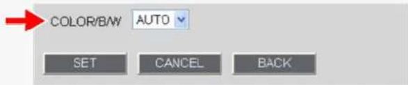
text_image
COLOR/BW AUTO SET CANCEL BACKAUTO (for lens that does not support infrared focusing):
FIX (for lens that supports infrared focusing):
Adjusts the camera to the last-set back focus position each time switching to the color/black-and-white video mode occurs.
Fixes the camera to the last-set back focus position regardless of switching to the color/black-and-white video mode.
MIRROR
Use the mirror function to electronically flip the displayed subject.
If you installed the camera upside down or intend to monitor the subject in the mirror, configure the following settings according to the installation environment of the camera.
In [MIRROR], select the desired mirror mode and click SET.
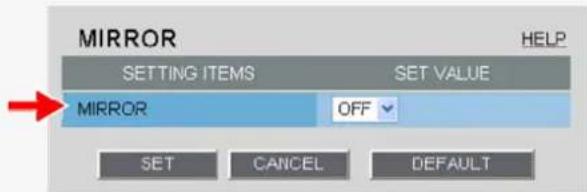
text_image
MIRROR SETTING ITEMS SET VALUE MIRROR OFF SET CANCEL DEFAULT HELPOFF: Disables the mirror mode (normal video).
HV: Flips the video vertically and horizontally.
H: Flips the video horizontally.
V: Flips the video vertically.
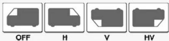
text_image
OFF H V HV
The configured settings will be applied commonly to "CAM1" and "CAM2" selected under [VIEW].
PRIVACY MASK
You can configure the privacy mask settings to hide specific portions of surveillance video for privacy protection. When a privacy mask is set, the resolution, frame rate, and image quality of the live video image may be limited.

The configured settings will be applied commonly to "CAM1" and "CAM2" selected under [VIEW].
1 Click [PRIVACY MASK] in the sub menu.
The PRIVACY MASK SETTINGS screen appears.

The mask setting screen shows the video at the angle of view that you see on the live screen.
2 Drag the mouse over the live video image to select the area you want to mask.
A mask pattern appears over the selected area.
You can set up to eight mask patterns on the screen.
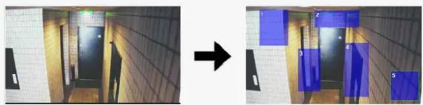
natural_image
Two-panel image showing a hallway with blue rectangular overlays on walls, one increasing and the other decreasing (no text or symbols)
To select a mask pattern, just click on it. The selected mask pattern is shown with a yellow green border.
To move a mask pattern, select it and then drag the mouse. To resize a mask pattern, place the mouse pointer over its border and then drag the mouse.
To delete a set mask pattern, click the DELETE button corresponding to the pattern number or drag it out of the screen.
3 Select the [SETTING ITEMS] check box.
Each mask pattern for which you selected the check box appears on the live screen. You may select two or more check boxes.
![SANYO VCC-HD2100P - Select the [SETTING ITEMS] check box. - 1](/content/2026/05/817427/images/f7228b078296c1806c7c436ff8290a597e570b348f6da1f97dbda2b1cc25be16.jpg)
text_image
SETTING ITEMS SET VALUE MASK 1 DELETE MASK 2 DELETE MASK 3 DELETE MASK 4 DELETE MASK 5 DELETE MASK 6 DELETE MASK 7 DELETE MASK 8 DELETE COLOR BLACK SEMI TRANSPARENT OFF SET CANCEL DEFAULT BACK4 In [COLOR], select the color of the mask pattern(s).
BLACK, GREY, WHITE, RED, BLUE
5 In [SEMI TRANSPARENT], select whether to enable or disable the transparency of the mask pattern(s).
OFF (Disables transparency), ON (Enables transparency)
6 Click SET and then BACK.
The settings are saved and you return to the sub menu.
ALARM SETTINGS
Click ALARM in the configuration menu to display the ALARM SETTINGS screen.
If you want the camera to record surveillance video or transmit a warning signal by detecting an alarm condition, configure the following settings on this screen.
A Detecting an alarm condition via alarm input terminal
B Detecting an alarm condition via built-in motion sensor
c Outputting an alarm signal from alarm output terminal

Required operation privilege: admin, operator
A Detecting an alarm condition via alarm input terminal
Configure the input conditions of each alarm input terminal provided on the rear face of the camera.
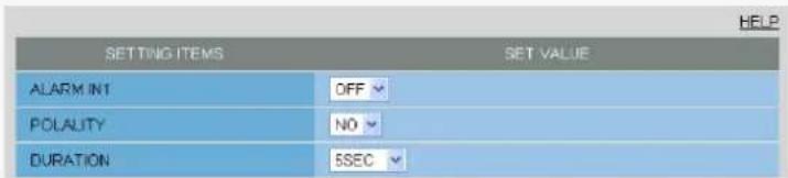
text_image
SETTING ITEMS SET VALUE ALARM INT OFF POLALITY NO DURATION 5SEC
Before you start the following procedure, connect an external alarm device to one of the alarm input terminals ("ALARM IN1" in this example). For details, refer to the "Alarm Input/Output Terminal Connections" section.

If you set [CLOCK ADJUST] to "ALARM IN1" on the CLOCK SETTINGS screen, the ALARM IN1 terminal serves dedicatedly as a time adjustment terminal. In this case, the [SET VALUE] column of [ALARM IN1] shows "CLOCK IN" in, allowing you to select a value in [POLARITY] only. With VCC-HD2300P/VCC-HD2300: if you set [DAY/NIGHT] to "COLOR" and [EXT ALARM] to "ALARM IN1" or "ALARM IN2" under [DAY/NIGHT SETTINGS] on the CAMERA SETTINGS screen, the corresponding terminal will serve as a Day/Night switching terminal. In this case, "DAY/NIGHT" is displayed in [SETTING ITEMS], allowing you to select only the item [POLARITY].
1 In [ALARM IN1], select "ON".
2 In [POLARITY], select the signal polarity of the alarm input terminal.
NO (Normally Open): The terminal is normally open and closes when an alarm signal is received. NC (Normally Closed): The terminal is normally closed and opens when an alarm signal is received.
3 In [DURATION], select how long you want the alarm state to be retained when the terminal receives an alarm signal and click SET.
The terminal will not accept subsequent alarm signals until the set duration expires.
5SEC, 10SEC, 15SEC, 20SEC, 30SEC, 45SEC, 1MIN, 2MIN, 3MIN, 4MIN, 5MIN
CC (Retains the alarm state as long as the alarm signal persists.)

The alarm state will be retained for at least 5 seconds even if the alarm signal is instantaneous. The configured duration value will be reset to the factory default value if you change any setting on the ALARM SETTINGS screen while an alarm state is retained.
To configure the ALARM IN2 terminal to detect an alarm condition, select "ON" in [ALARM IN2] and specify the input conditions for it in the same way as for the ALARM IN1 terminal.

Detecting an alarm condition via built-in motion sensor
This camera offers the built-in motion sensor function that automatically detects motion in the subject. The motion sensor detects an alarm condition in three ways as follows.
A Disabling motion detection in masked areas
B Detecting motion in specific areas
A
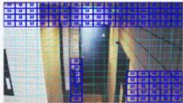
text_image
Cropped image showing a grid-based interface with labeled boxes and numerical data, likely from a software or document.B
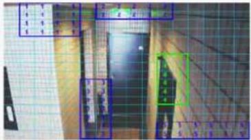
text_image
Technical diagram with labeled components and grid lines, showing structural elements and annotations
You cannot configure the motion sensor function if the electronic sensitivity boosting (SENSE UP) or the long exposure shutter mode (LONG) is enabled.

Disabling motion detection in masked areas
Use the motion masking function to detect motion in the whole screen area, except for masked areas. Set a mask over any swaying tree, flickering light source, or other object to prevent unwanted detection.
1 On the ALARM SETTINGS screen, in [MOTION], select "MASKING".
2 In [DURATION], select how long you want the alarm state to be retained when the motion sensor detects motion and click DETAIL.
The motion mask configuration screen appears.
5SEC, 10SEC, 15SEC, 20SEC, 30SEC, 45SEC, 1MIN, 2MIN, 3MIN, 4MIN, 5MIN
CC (Retains the alarm state as long as the motion alarm persists.)

The terminal will not accept subsequent alarm signals until the set duration expires.
The alarm state will be retained for at least 5 seconds even if the motion is instantaneous.
The configured duration value will be reset to the factory default value if you change any setting on the ALARM SETTINGS screen while an alarm state is retained.
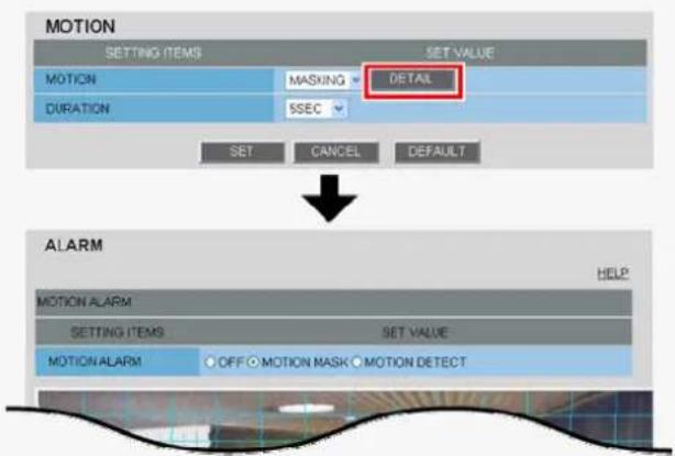
text_image
MOTION SETTING ITEMS MASKING DETAIL DURATION 5SEC SET CANCEL DEFAULT ALARM MOTION ALARM SETTING ITEMS SET VALUE MOTION ALARM OFF MOTION MASK MOTION DETECT HELP
To switch the alarm detection method, in [MOTION ALARM], click the desired radio button.
3 Drag the mouse over live video/image to select the area you want to mask.
The masked area is indicated by blue-bordered grid cells each containing the letter "M". You can mask as many areas as you want without limitation.
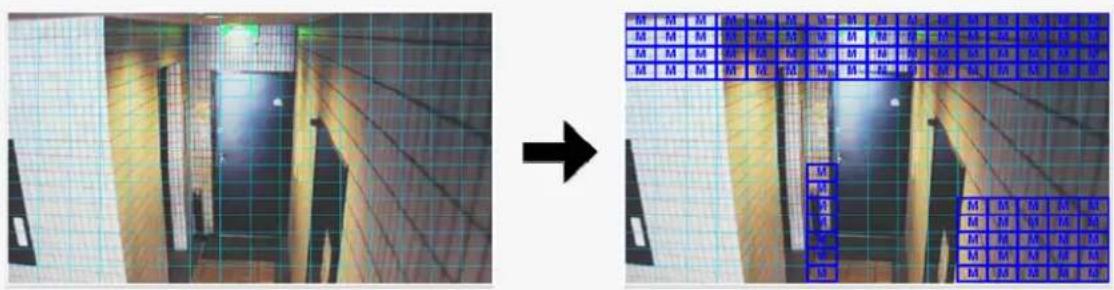
text_image
Street photo with visible store signboards and a grid overlay showing building signage
You can unmask one grid cell at a time by clicking each grid cell in a masked area. To deselect a block of grid cells in the masked area, right-click one of grid cell and drag the mouse.
4 In [SENSITIVITY], select the detection sensitivity.
The higher the value, the lower the sensitivity.
1 to 9
![SANYO VCC-HD2100P - In [SENSITIVITY], select the detection sensitivity. - 1](/content/2026/05/817427/images/04f648b3f25609cc9607a336936c7de771c627dfba02580aae36c0c0ce15725f.jpg)
text_image
4 SENSITIVITY 5 TEST TEST SET CANCEL DEFAULT BACKChecking how the motion sensor works
Click TEST
If any motion is detected in a grid cell outside the masked area(s), that grid cell will be shown in red. Correct the detection conditions as required.

While the sensor is working, this button is labeled as END. To finish checking the motion sensor, click the button.
5 Click SET and then BACK.
The settings are saved and you return to the ALARM SETTINGS screen.
B Detecting motion in specific areas
Use the motion detection function to detect motion in specific areas of the subject.
1 On the ALARM SETTINGS screen, in [MOTION], select "DETECT".
2 In [DURATION], select how long you want the alarm state to be retained when the motion sensor detects motion and click DETAIL.
The detection area configuration screen appears.
5SEC, 10SEC, 15SEC, 20SEC, 30SEC, 45SEC, 1MIN, 2MIN, 3MIN, 4MIN, 5MIN
CC (Retains the alarm state as long as the motion alarm persists.)
![SANYO VCC-HD2100P - In [DURATION], select how long you want the alarm state to be retained when the motion sensor detects motion and click DETAIL. - 1](/content/2026/05/817427/images/691979a8f3255b58888726482b8368f635112bf723e77f2dbbc6ad07f81b7ad2.jpg)
The terminal will not accept subsequent alarm signals until the set duration expires.
The alarm state will be retained for at least 5 seconds even if the motion is instantaneous.
The configured duration value will be reset to the factory default value if you change any setting on the ALARM SETTINGS screen while an alarm state is retained.
![SANYO VCC-HD2100P - In [DURATION], select how long you want the alarm state to be retained when the motion sensor detects motion and click DETAIL. - 2](/content/2026/05/817427/images/ebc2e298990a67d10f73e1305f7576c19c523863f7f10be2dafe64c382de2c1a.jpg)
text_image
MOTION SETTING ITEMS SET VALUE MOTION DETECT DETAIL DURATION 5SEC SET CANCEL DEFAULT ALARM HELP MOTION ALARM SETTING ITEMS SET VALUE MOTION ALARM OFF ○ MOTION MASK ○ MOTION DETECT![SANYO VCC-HD2100P - In [DURATION], select how long you want the alarm state to be retained when the motion sensor detects motion and click DETAIL. - 3](/content/2026/05/817427/images/4106b595a02200d55c7ff000550bb5ec2e9c823a23f2bab726bbe9a598b74f1b.jpg)
To switch the alarm detection method, in [MOTION ALARM], click the desired radio button.
3 Drag the mouse over live video/image to select the detection area.
You can set up to five detection areas.
Each detection area will be given a number (1 to 5) as you add it. The currently selected area is shown in yellow green.
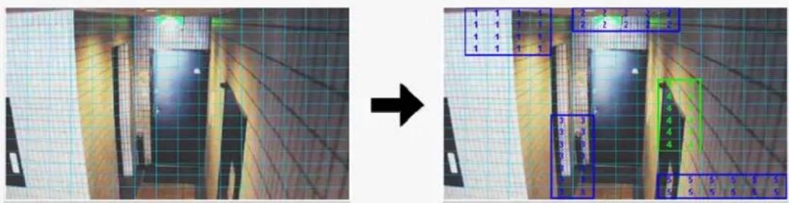
text_image
Street photo with visible store signboards and a directional arrow indicating transformation or change
To move a detection area, select it and then drag the mouse.
To resize a detection area, place the mouse pointer over its border and then drag the mouse.
To delete a set detection area, click the DELETE button (1) corresponding to the detection area number or drag it out of the screen.
4 In [AREA], select the check box next to the area number of the area you want to enable.
You may select two or more check boxes.
![SANYO VCC-HD2100P - In [AREA], select the check box next to the area number of the area you want to enable. - 1](/content/2026/05/817427/images/76bc7edbe1dd9ca8b5730c70776727a9d564df002e8c7504893a1d2432554619.jpg)
flowchart
graph TD
    A["TEST"] --> B["AREA"]
    B --> C["SENSITMTY"]
    C --> D["DELETE"]
    C --> E["DELETE"]
    C --> F["DELETE"]
    C --> G["DELETE"]
    style A fill:#f9f,stroke:#333
    style B fill:#ccf,stroke:#333
    style C fill:#cfc,stroke:#333
    style D fill:#fcc,stroke:#333
    style E fill:#fcc,stroke:#333
    style F fill:#fcc,stroke:#333
    style G fill:#fcc,stroke:#333
5 In [SENSITIVITY], select the detection sensitivity.
You can adjust the detection sensitivity to prevent unwanted detection.
The higher the value, the lower the sensitivity.
1 to 9
Checking how the motion sensor works
Click TEST (2).
If any motion is detected in a grid cell in the detection area, that cell will be shown in red.
Correct the detection conditions as required.

While the sensor is working, this button is labeled as END. To finish checking the motion sensor, click the button.
6 Click SET and then BACK.
The settings are saved and you return to the ALARM SETTINGS screen.

Outputting an alarm signal from alarm output terminal
Configure the output conditions for each alarm output terminal.
A Configuring automatic alarm output:
Configure the terminal so that it outputs an alarm signal automatically when an alarm condition is detected.
B Configuring remote alarm output:
Configure the terminal so that it outputs an alarm signal when the corresponding Remote Alarm button is clicked.

Before you start the following procedure, connect an external alarm device to one of the alarm output terminals ("ALARM OUT1" in this example).
For details, refer to the "Alarm Input/Output Terminal Connections" section.
A Configuring Automatic Alarm Output
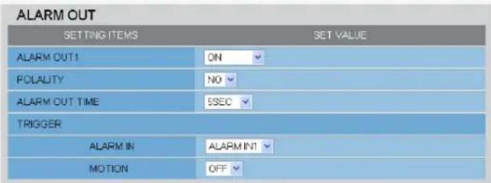
text_image
ALARM OUT SETTING ITEMS SET VALUE ALARM OUT1 ON POLALITY NO ALARM OUT TIME 5SEC TRIGGER ALARM IN ALARM INT MOTION OFF1 In [ALARM OUT1], select "ON".
2 In [POLARITY], select the signal polarity of the alarm output terminal.
NO (Normally Open): The terminal is normally open and closes when an alarm signal is output.
NC (Normally Closed): The terminal is normally closed and opens when an alarm signal is output.
3 In [ALARM OUT TIME], select how long you want the terminal to output an alarm signal.
The terminal will stop outputting the alarm signal when the set alarm output time expires.
2SEC, 5SEC, 10SEC, 15SEC, 30SEC, 45SEC, 1MIN, 2MIN, 3MIN, 4MIN, 5MIN

The alarm output time must be specified within the duration of the alarm input terminal you select under [TRIGGER].
4 Under [TRIGGER], configure the following alarm output conditions and click SET.

text_image
TRIGGER ALARM IN ALARM IN1 MOTION OFFALARM IN
Specify the alarm input terminal to which the alarm input device is connected. The ALARM OUT 1 terminal outputs an alarm signal when this terminal receives an alarm signal.
ALARM IN1: The terminal outputs an alarm signal when the ALARM IN1 terminal receives an alarm signal.
ALARM IN2: The terminal outputs an alarm signal when the ALARM IN2 terminal receives an alarm signal.
MOTION
You can configure the alarm output conditions in conjunction with the motion alarm function.
OFF: The terminal does not output an alarm signal even when motion is detected in the subject by the motion sensor.
ON: The terminal outputs an alarm signal when motion is detected in the subject by the motion sensor.
* To configure the ALARM OUT 2 terminal to output an alarm signal, select "ON" in [ALARM OUT2] and specify the output conditions for it in the same way as for the ALARM OUT1 terminal.
B Configuring Remote Alarm Output
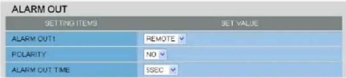
text_image
ALARM OUT SETTING ITEMS SET VALUE ALARM OUT1 REMOTE POLARITY NO ALARM OUT TIME SSEC1 In [ALARM OUT1], select "REMOTE".
![SANYO VCC-HD2100P - In [ALARM OUT1], select "REMOTE". - 1](/content/2026/05/817427/images/0a049f0322158aff82c72821aa36789df5aab41ece9aca3f3f4e96b374a4449c.jpg)
Selecting "REMOTE" does not cause the terminal to output an alarm signal automatically even if an alarm condition is detected.
2 In [POLARITY], select the signal polarity of the alarm output terminal.
NO (Normally Open): The terminal is normally open and closes when an alarm signal is output.
NC (Normally Closed): The terminal is normally closed and opens when an alarm signal is output.
3 In [ALARM OUT TIME], select how long you want the terminal to output the alarm signal and click SET.
The terminal will stop outputting the alarm signal when the set alarm output time expires.
2SEC, 5SEC, 10SEC, 15SEC, 30SEC, 45SEC, 1MIN, 2MIN, 3MIN, 4MIN, 5MIN
CC (Stops outputting the alarm signal when the corresponding Remote Alarm button is clicked on the live screen.)
To configure the ALARM OUT 2 terminal to output an alarm signal when a Remote Alarm button is clicked, select "REMOTE" in [ALARM OUT2] and specify the output conditions for it in the same way as for the ALARM OUT1 terminal.
E-MAIL SETTINGS
Click E-MAIL in the configuration menu to display the E-MAIL SETTINGS screen.
Using the automatic e-mail transmission function, you can send an e-mail attached with an image if an alarm is detected, or after a fixed interval.
A Configuring basic e-mail transmission settings
B Configuring recipient e-mail addresses (RECIPIENT MAIL ADDRESS)
c Configuring authentication conditions (AUTHENTICATION)
D Configuring transmission conditions
E Configuring e-mail text (SUBJECT/TEXT)
Log information display area (LOG): In [LOG], you can view the SMTP (e-mail) transmission log.

Required operation privilege: admin, operator

For network-related settings, consult your network administrator.
A Configuring basic e-mail transmission settings
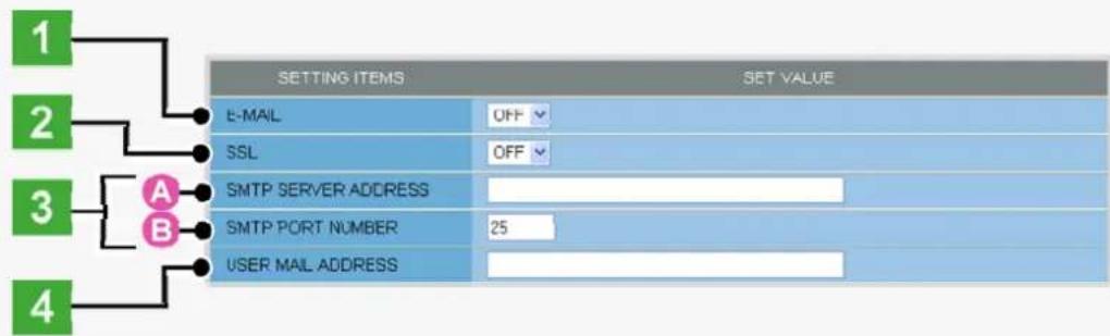
flowchart
graph TD
    A["1"] --> B["2"]
    B --> C["3"]
    C --> D["4"]
    D --> E["A"]
    D --> F["B"]
    E --> G["E-MAIL OFF"]
    F --> H["SSL OFF"]
    G --> I["SMTP SERVER ADDRESS"]
    H --> J["SMTP PORT NUMBER 25"]
    I --> K["USER MAIL ADDRESS"]
    J --> L["SET VALUE"]
    K --> M["SET VALUE"]
1 In [E-MAIL], select "ON" to enable the e-mail transmission function.
2 In [SSL], select "ON" to use SSL communication.
If your e-mail server supports SSL, you can encrypt e-mail transmission.
3 Configure your e-mail server.
Type the following information on your e-mail server.
A SMTP SERVER ADDRESS
Type the address of your SMTP server (up to 64 alphanumeric characters).
B SMTP PORT NUMBER
Type the incoming port number of your SMTP server.
The available port numbers are 0 to 65535.

Normally, use the default value "25". However, if you are using the submission port for security reasons or in other cases where you need to do so, change the default value.
4 In [USER MAIL ADDRESS], type the sender's e-mail address and click SET.
Here, you can type only one e-mail address (up to 64 alphanumeric characters).

Configuring recipient e-mail addresses (RECIPIENT MAIL ADDRESS)
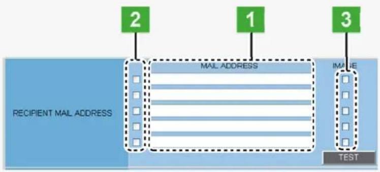
flowchart
graph LR
    A["RECIPIENT MAIL ADDRESS"] --> B["MAIL ADDRESS"]
    B --> C["IMAGE"]
    C --> D["TEST"]
    style A fill:#333,stroke:#fff,color:#fff
    style B fill:#999,stroke:#000,color:#fff
    style C fill:#999,stroke:#000,color:#fff
    style D fill:#ccc,stroke:#000,color:#000
1 In [MAIL ADDRESS], type the recipient e-mail addresses.
Here, you can type up to five e-mail addresses (up to 64 alphanumeric characters for each).
2 Select the check box for each e-mail address to which you want to send e-mails.
You can send e-mails to the selected e-mail address(es).
3 To attach an image file to an e-mail, select the [IMAGE] check box of the corresponding recipient address and click SET.

The attached image file will have the following file name:
CAMERA ID +_yymmddhhmmss.jpg
CAMERA ID is the leading four characters of the camera title. However, any of the following symbols, if included, will be replaced by a “-” (hyphen):
/ (slash), \ (backslash), ? (question mark), * (asterisk), : (colon), ; (semicolon), ' (single quote), " (double quote), < (less-than sign), > (greater-than sign), | (broken bar)
* To send a test e-mail, click TEST.
A test e-mail is sent to each recipient e-mail address for which you selected the check box in Step 2.

The subject (SUBJECT) of this test e-mail will be "TEST".

Configuring authentication conditions (AUTHENTICATION)
To perform an authentication check, you need to configure the authentication conditions.
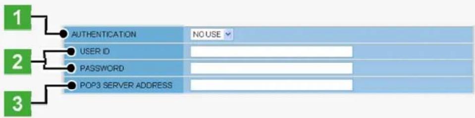
flowchart
graph TD
    A["1"] --> B["AUTHENTICATION NO USE"]
    C["2"] --> D["USER ID"]
    E["3"] --> F["PASSWORD"]
    G["4"] --> H["POP3 SERVER ADDRESS"]
1 In [AUTHENTICATION], select the authentication method.

NO USE, POP3, SMTP
2 In [USER ID] and [PASSWORD], type the user ID and password, respectively.
Type the user ID (up to 48 alphanumeric characters) and password for authentication (up to 20 alphanumeric characters).
3 In [POP3 SERVER ADDRESS], type your POP3 server address and click SET.
If you selected "POP3" in [AUTHENTICATION], type the IP address or domain name of your POP3 server (up to 64 alphanumeric characters).

Configuring transmission conditions
| TRIGGER | NETWORK FAILURE |
| NETWORK FAILURE TIME | 15SEC |
| INTERVAL | 1MIN |
| JPEG IMAGE | OFF |
1 In [TRIGGER], select the e-mail transmission conditions.
INTERVAL: Sends an e-mail at fixed intervals.
ALARM IN1: Sends an e-mail when the ALARM IN1 terminal receives an alarm signal.
ALARM IN2: Sends an e-mail when the ALARM IN2 terminal receives an alarm signal.
MOTION ALARM: Sends an e-mail when the motion sensor detects motion in the subject.
ALARM OUT1: Sends an e-mail when the ALARM OUT 1 terminal outputs an alarm signal.
ALARM OUT2: Sends an e-mail when the ALARM OUT 2 terminal outputs an alarm signal.
NETWORK
FAILURE: Sends an e-mail when the camera detects a network failure during network recording.
A If you selected "NETWORK FAILURE" ...
In [NETWORK FAILURE TIME], select the time from the occurrence of a network failure until the camera recognizes it as a recording trigger.
15SEC, 20SEC, 30SEC, 40SEC, 50SEC, 1MIN, 2MIN, 3MIN, 4MIN, 5MIN

The setting values are interlocked among E-MAIL SETTINGS, and FTP SETTINGS screens. (Note that the setting configured most recently will take precedence.)
B If you selected "INTERVAL" ...
In [INTERVAL], select the interval between e-mail transmissions.
1MIN, 2MIN, 3MIN, 4MIN, 5MIN, 10MIN, 15MIN, 30MIN, 1HOUR, 2HOUR, 3HOUR, 4HOUR, 5HOUR, 6HOUR, 7HOUR, 8HOUR, 12HOUR, 24HOUR
2 To attach a JPEG image file to an e-mail, in [JPEG IMAGE] select "ON", and click SET.

You need to configure the JPEG image conditions on the CODEC/STREAMING SETTINGS screen.
E Configuring e-mail text (SUBJECT/TEXT)
Here, configure the subject and message text portions of the e-mail.
| SUBJECT | |
| TEXT | |
| LOG |

An e-mail consists of the following portions.
Subject
Camera Title
Data and time
Camera's IP address
Message (TEXT)
The camera title, date and time, IP address will be included automatically.
1 In [SUBJECT], type the subject (title) of the e-mail.
You can type up to 32 alphanumeric characters.
2 In [TEXT], type the message text and click SET.
You can type up to 64 alphanumeric characters.
![SANYO VCC-HD2100P - In [TEXT], type the message text and click SET. - 1](/content/2026/05/817427/images/e1c5c60ce501ba2596acd27679b2c4a7eafc9f2bf84e33938363083f34e6b6a3.jpg)
In the [SUBJECT] and [TEXT] fields, you can use special symbol characters.
FTP SETTINGS
Click FTP in the configuration menu to display the FTP SETTINGS screen.
If you want to record images from the camera to an FTP server via the network, configure the FTP server settings and the image transmission conditions on this screen.
A Configuring FTP server settings
B Configuring transmission conditions

Required operation privilege: admin, operator
You can send JPEG images only.
A Configuring FTP Server Settings
1 In [FTP], select "ON".
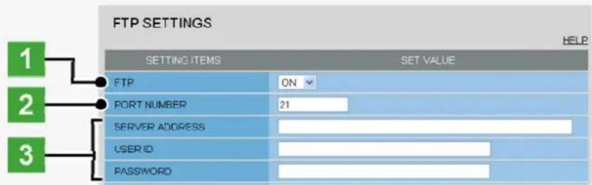
text_image
FTP SETTINGS 1 2 3 SETTING ITEMS SET VALUE FTP ON PORT NUMBER 21 SERVER ADDRESS USER ID PASSWORD2 In [PORT NUMBER], type the control port number configured on the server.
Type a number between 1 and 65535. This port number is normally "21" (default).
3 In [SERVER ADDRESS], type the server address. Then, in [USER ID] and [PASSWORD], type the user ID and password, respectively.
The number of characters you can type in these fields is as follows.
SERVER ADDRESS: Up to 64 alphanumeric characters
USER ID: Up to 48 alphanumeric characters
PASSWORD: Up to 20 alphanumeric characters
4 To use the passive FTP mode, in [FTP PASSIVE], select "USE".
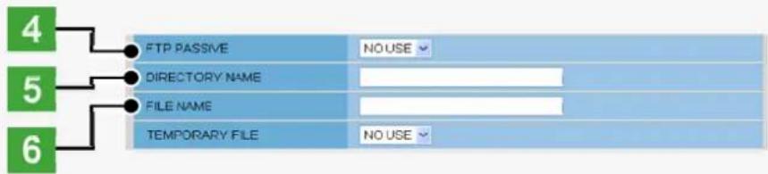
text_image
FTP PASSIVE DIRECTORY NAME FILE NAME TEMPORARY FILE NO USE
When [FTP PASSIVE] is set to "USE", users must specify a valid port number when making a connection request for sending data to the server.
5 In [DIRECTORY NAME], specify the name of the directory you want to create on the server.
You can type up to 32 alphanumeric characters.

If no directory name is specified, the system will automatically generate the following directory name.
When sending an alarm image in the event of an error: ALARM_FTP
When sending an image in fixed intervals: INTERVAL_FTP
6 In [FILE NAME], specify the name of the image file you want to send and click SET.
You can type up to 32 alphanumeric characters.
![SANYO VCC-HD2100P - In [FILE NAME], specify the name of the image file you want to send and click SET. - 1](/content/2026/05/817427/images/fcdbcd7662b0d4a56d69e7aeb660bd3e41db619be85acbc70eb99d6ef47ffade.jpg)
Each image file will have a file name consisting of the specified file name, the date/time, and the alarm factor (if [TRIGGER] is set to other than "INTERVAL"):
[FILE NAME] + [yy_mm_dd_hh_mm_ss] + [alarm_factor] + [0001 (Serial No.).jpg]
If no file name is specified, the system will enter "sanyo" for the [FILE NAME].
\* To use a temporary file, set [TEMPORARY FILE] to "USE".
This causes each image to be stored as a temporary file on the FTP server and then renamed to the specified file name.
The FTP server will store a single temporary file for the most recent image with the specified file name.
![SANYO VCC-HD2100P - \* To use a temporary file, set [TEMPORARY FILE] to "USE". - 1](/content/2026/05/817427/images/9dc250cf7e7995043c35e2aca0df676e44039fdc01908854bfa80a9de4c9f8d4.jpg)
Temporary file name: sanyo_ftp_temp_[IP address].temp
Although the temporary file will be renamed to the specified file name and then stored in the specified directory as explained in steps 5 to 6, the renamed file name will not include the date/time and alarm factor information.
Both the temporary and permanent files will be overwritten if the same file name exists.
B Configuring transmission conditions
In [TRIGGER], select the image transmission trigger condition, configure items as necessary and click SET.
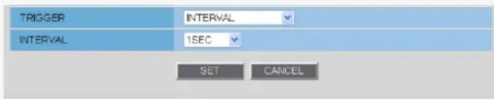
text_image
TRIGGER INTERVAL INTERVAL 1SEC SET CANCELINTERVAL: Sends a still image in fixed intervals.
ALARM IN1: Sends a still image when the ALARM IN1 terminal receives an alarm signal.
ALARM IN2: Sends a still image when the ALARM IN2 terminal receives an alarm signal.
MOTION: Sends a still image when the motion sensor detects motion in the subject.
ALARM OUT1: Sends a still image when the ALARM OUT 1 terminal outputs an alarm signal.
ALARM OUT2: Sends a still image when the ALARM OUT 2 terminal outputs an alarm signal.
NETWORK FAILURE: Sends a still image when the camera detects a network failure during network recording.

You need to configure the alarm input/output conditions on the ALARM SETTINGS screen.
A If you selected "NETWORK FAILURE" ...
In [NETWORK FAILURE TIME], select the time from the occurrence of a network failure until the camera recognizes it as a recording trigger.
15SEC, 20SEC, 30SEC, 40SEC, 50SEC, 1MIN, 2MIN, 3MIN, 4MIN, 5MIN

The setting values are interlocked among E-MAIL SETTINGS, and FTP SETTINGS screens. (Note that the setting configured most recently will take precedence.)
B If you selected "ALARM IN1/2", "MOTION", or "ALARM OUT1/2" ...
In [DURATION], select the image transmission duration.
5SEC, 10SEC, 20SEC, 40SEC, 1MIN, 2MIN, 3MIN, 4MIN, 5MIN, 10MIN, 15MIN
c If you selected "INTERVAL", "ALARM IN1/2", "MOTION", or "ALARM OUT1/2" ...
In [INTERVAL], select the interval between e-mail transmissions.
1SEC, 2SEC, 3SEC, 5SEC, 10SEC, 30SEC, 1MIN, 3MIN, 5MIN, 10MIN, 15MIN, 30MIN, 1HOUR, 2HOUR, 3HOUR, 4HOUR, 5HOUR, 6HOUR, 8HOUR, 12HOUR, 24HOUR

The interval options available when you selected "ALARM IN1/2", "MOTION", or "ALARM OUT1/2" in [TRIGGER] are only "1SEC" to "15MIN".
In [INTERVAL], the pull-down menu will only show options that do not exceed the [DURATION] setting.
SECURITY SETTINGS
Click SECURITY in the configuration menu to display the SECURITY SETTINGS screen.
Configuring the security function on this screen enables you to restrict the PCs that can access the camera.

Required operation privilege: admin, operator1
1 In [SECURITY FUNCTION], select "ON".
2 In [DEFAULT POLICY], select the global access policy.
Here, you specify the access policy for all PCs, except for those for which you configure the access settings in [NETWORK ADDRESS/SUBNET] (3).
AUTHORIZED: Permits access to the camera.
REJECTED: Rejects access to the camera.
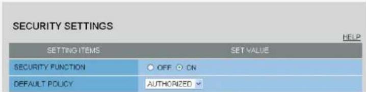
text_image
SECURITY SETTINGS SETTING ITEMS SET VALUE SECURITY FUNCTION ○ OFF ○ ON DEFAULT POLICY AUTHORIZED3 In [NETWORK ADDRESS/SUBNET], configure the access settings for individual PCs.
Type the IP address and the subnet mask of each PC and specify whether or not to grant it access to the camera. You can configure the access settings for up to 10 PCs.
AUTHORIZED: Permits access to the camera.
REJECTED: Rejects access to the camera.

If there are duplicate address/subnet mask settings, one in the uppermost row is valid.
Example 1: When the global access policy (DEFAULT POLICY) is set to “AUTHORIZED” and the individual access policy is set to “REJECTED”
The PCs configured in [NETWORK ADDRESS/SUBNET 1] and [NETWORK ADDRESS/SUBNET 2] cannot access the camera because their individual access policy is "REJECTED".

text_image
SECURITY FUNCTION OFF ON DEFAULT POLICY AUTHORIZED NETWORK ADDRESS / SUBNET1 192 168 0 20 / 32 REJECTED NETWORK ADDRESS / SUBNET2 192 168 0 200 / 32 REJECTEDExample 2: When the global access policy (DEFAULT POLICY) is set to “REJECTED” and the individual access policy is set to “AUTHORIZED” ...
The PCs configured in [NETWORK ADDRESS/SUBNET 1] and [NETWORK ADDRESS/SUBNET 2] can access the camera because their individual access policy is "AUTHORIZED".

text_image
SECURITY FUNCTION OFF ON DEFAULT POLICY REJECTED NETWORK ADDRESS / SUBNET1 192 168 0 1 / 32 AUTHORIZED NETWORK ADDRESS / SUBNET2 192 168 0 100 / 32 AUTHORIZED4 Click SET.
The settings are saved.
OPTION SETTINGS
Click OPTION in the configuration menu to display the OPTION SETTINGS screen.
On this screen, you can perform system-related operations and log checks.
Click SET to execute or start the intended operation.

Required operation privilege: admin, operator1
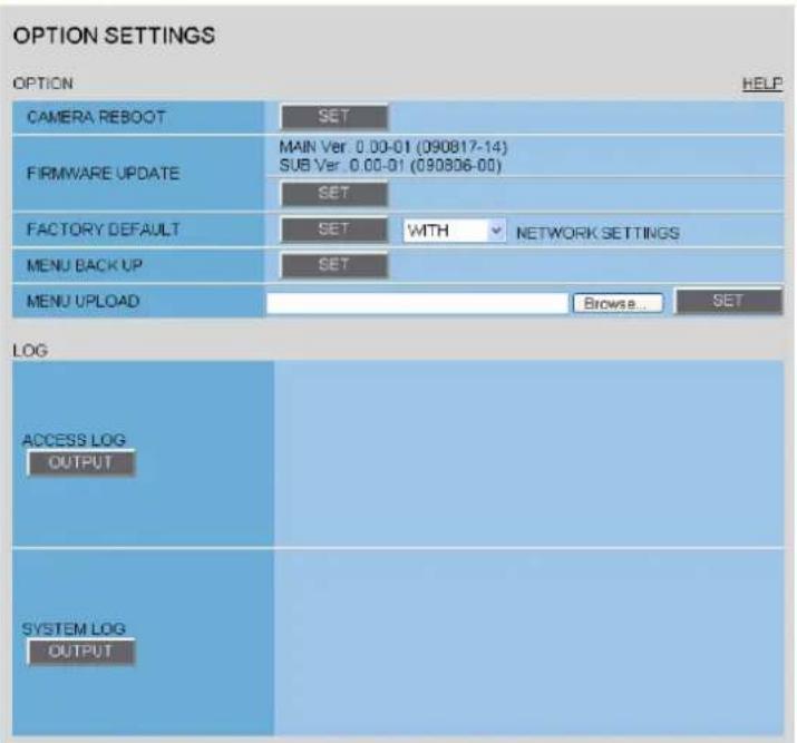
text_image
OPTION SETTINGS OPTION HELP CAMERA REBOOT SET FIRMWARE UPDATE MAIN Ver. 0.00-01 (090817-14) SUB Ver. 0.00-01 (090806-00) SET FACTORY DEFAULT SET WITH NETWORK SETTINGS MENU BACK UP SET MENU UPLOAD Browse... SET LOG ACCESS LOG OUTPUT SYSTEM LOG OUTPUTRebooting Camera (CAMERA REBOOT)
If the camera stops functioning for some reason or other, in [CAMERA REBOOT], click SET to reboot the camera system.
Updating Firmware Version (FIRMWARE UPDATE)
You can update the camera's firmware to the latest version.
1 Click SET.
The FIRMWARE UPDATE screen appears.
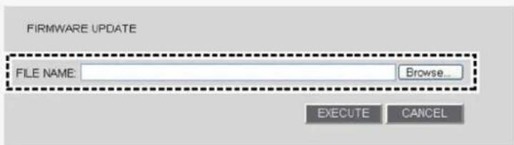
text_image
FIRMWARE UPDATE FILE NAME: Browse... EXECUTE CANCEL2 Click BROWSE and select the firmware updater file.
3 Click EXECUTE.
The firmware update process starts. When the update process is completed, the camera system reboots and you reconnect to the camera automatically.
Once you reconnect to the camera, redisplay the OPTION SETTINGS screen and confirm that the firmware version has been updated.

Do not perform any operations on the screen or turn off the camera until the firmware update process is completed.
While the firmware is being updated, all camera functions stop working temporarily.
Restoring Factory Default Settings (FACTORY DEFAULT)
You can restore all the settings you have configured to the factory default settings.

In [NETWORK SETTINGS], select whether or not to restore the settings including the network settings and click SET.
WITH: Includes the network settings.
WITHOUT: Excludes the network settings.
An operation confirmation dialog box opens.
Backing Up Configured Settings (MENU BACKUP)
You can save the settings you have configured using the backup function.

In [MENU BACKUP], click SET. Then, select SAVE in a save confirmation dialog box and specify the backup destination file.

All the settings on the NETWORK SETTINGS screen and the [DATE/TIME] setting on the CLOCK SETTINGS screen are not saved.
Uploading Backed Up Settings (MENU UPLOAD)
You can restore the saved configuration settings of the camera from a backup file.

text_image
MENU UPLOAD Browse... SETClick BROWSE, select the backup file you want to upload, and click SET.
The backup file is uploaded to the camera to restore the saved configuration settings.
When the upload process is completed, the camera system reboots.

All the settings on the NETWORK SETTINGS screen and the [DATE/TIME] setting on the CLOCK SETTINGS screen are not restored.
Viewing Logs (LOG)
Under [LOG], you can view the access and system logs.
You can click OUT PUT to output the content of each log into a text file.

The log information is deleted when the camera is powered off.
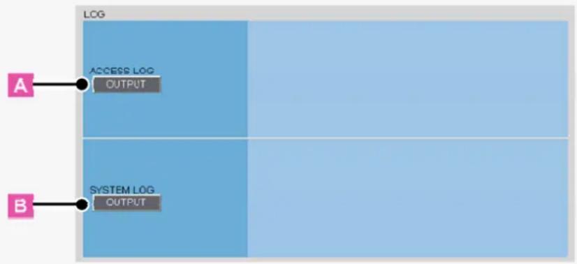
text_image
LOG ACCESS LOG OUTPUT SYSTEM LOG OUTPUTA ACCESS LOG
Shows the history of access to the camera in chronological order (up to 100 entries).
Date and time, user name, authentication check result (OK/NG), connection destination IP address
B SYSTEM LOG
Shows a history of system operation in chronological order (up to 200 entries).

VCC-HD2300/HD2300P
VCC-HD2100/HD2100P
Chapter 6
Q&A
Accessing the Camera
Control Panel/Tool Panel
CAMERA SETTINGS
Displaying LIVE video
Transmitting Image Data
Others
Accessing the Camera
I cannot access the camera.

1The camera IP address you entered is wrong.
Enter the correct IP address (URL) in the Web browser (Internet Explorer).
2The camera port number you entered is wrong.
If you are using a port number other than 80, enter the correct port number in the Web browser (Internet Explorer).
3 Your have accessed with "http://" where you should be using HTTPS.
When using HTTPS, access with "https://". Also make sure to enter the port number if you have changed it to other than 443.
4 Access is restricted by security setting (The error message “403 forbidden” is displayed).
Contact your network administrator and ask him/her to change the security settings.
I cannot access the camera from within my home/company network.

1 The PC and camera IP addresses (local addresses) are configured with different subnet masks.
To use a PC and a camera within the same network, their subnet masks must be the same. Change settings so that the PC and camera have the same subnet mask.
2 The Web browser you are using is configured to connect to the Internet via proxy server.
Change the Web browser settings so that the use of proxy server is disabled.
3 The address you are trying to access is not a local address.
Enter a local address to access a camera located in the same network.
You cannot access a camera by entering a URL (or router global address and camera port number) registered with the dynamic DNS service or a URL that is compliant with the global address.
I cannot access the camera from the Internet.

1There is a wrong network setting in the camera.
Configure the default gateway correctly. When using the dynamic DNS service, check whether the entered DNS server address and domain name registered with the dynamic DNS service are correct.
2 Registration to the dynamic DNS service is yet to be done. (When using the dynamic DNS service)
Go to the dynamic DNS service site and check that the address for your camera is correctly registered.
3 Port forwarding is not configured on your router.
Port forwarding must be configured on your router for you to be able to access a camera from the Internet. For the configuration method, refer to your router's instruction manual.
4 Your router is configured with packet filtering or the like which restricts access from the Internet.
Change the settings in your router to allow access from the Internet. For the configuration method, refer to your router's instruction manual.
5 The IP address you entered is a local address (the one you use at your home).
When accessing via Internet, enter the global address (or the URL registered with the DDNS service) and port number of the camera as its IP address.
The camera has been suddenly disconnected.

1Another user has changed the password.
Configure the password settings again.
2Another user has changed the camera settings.
Access again after a while.
I get stuck at the Login screen.

The password is changed.
▶ Check the password and try again.
The access lamp does not go on.

1The LAN cable that connects directly to the camera is broken.
Connect the LAN cable.
2The LAN cable has been unplugged.
Connect the LAN cable.
3 The switching hub is turned off.
Turn on the switching hub.
I forgot the camera IP address/port number.

Press the SET button provided on the left-side face of the camera and, on the SELECT MENU screen, select [FIRMWARE VERSION] to check the firmware version.
Using the supplied "Auto IP Setup" software, execute a camera search.
Control Panel/Tool Panel
Buttons on the control panel/tool panel do not respond.

1 You do not have the required operation privilege.
Some buttons on the control panel/tool panel are operable only when you have an adequate operation privilege. Log in as a user with an adequate operation privilege.
2 You have not configured the required operation settings.
The Remote Alarm buttons are operable only when you have set [ALARM OUT 1/2] to "REMOTE" on the ALARM SETTINGS screen.
The [MENU] button does not respond.

Users other than admin and operator do not have the necessary privilege for performing operations from the configuration menu.
Without the required operation privilege, you will be presented with an authentication check dialog box when you click the [MENU] button on the live screen.
In this case, you can change the operation privilege by entering a user name with an adequate operation privilege and its password in the dialog box.
CAMERA SETTINGS
I cannot set [SENSE UP] in [IRIS].

You cannot set [SENSE UP] when [SHUTTER] is set to "SHORT" or "LONG".
Set [SHUTTER] to "OFF".

I cannot set [SHUTTER] to "SHORT" or "LONG".

You cannot configure the electronic shutter settings if you have set [SENSE UP] in [IRIS].
Set [SENSE UP] in [IRIS] to "OFF".
I cannot turn off the AGC.

1 If [DAY/NIGHT] is set to "AUTO", you cannot set [AGC] to "OFF". (When using VCC-HD2300P/VCC-HD2300)
Set [DAY/NIGHT] to "COLOR" or "B/W".
2 You cannot set [AGC] to "OFF" when [SENSE UP] in [IRIS] is set to "ON".
Set [SENSE UP] in [IRIS] to "OFF".
Displaying LIVE video
I cannot display LIVE video.

1ActiveX control is not installed in your PC.
Install ActiveX.
2 There is network congestion.
It may take some time until the screen can be displayed. Please wait.
The message "THE UNIT IS BUSY" appears on the screen if the number of simultaneously accessible users is already reached.
3 The version of the installed ActiveX control is old.
When another ActiveX control for network cameras is installed, video may not be displayed due to compatibility issues between the different versions. Install the H.264 Plug-In included in the supplied CD-ROM or the latest H.264 Plug-In you can download from SANYO CCTV System Web page.
4 The Web browser you are using for accessing the camera is configured to connect to the Internet via proxy server.
Some proxy servers block UDPs during H.264 browsing. In this case, either change the settings to browse H.264 using HTTP, or browse using JPEG.

I cannot install the "H.264 Plug-In" included in the supplied CD-ROM.

1The OS of your PC is not a recommended OS.
The OS must be Windows Vista, Windows XP Home Edition or Windows XP Professional SP2 or later for the H.264 Plug-In to run.
2 You are not logged into the PC with administrator privileges.
To install the H.264 Plug-In in a PC, you need OS administrator privileges. If you are logged in with user privileges, log out and log in again with administrator privileges to do the installation.

An error code appears and no LIVE video is displayed.

1The configured IP address or domain name is wrong.
Configure the IP address or domain name correctly.
2 If the address or domain name is correct, then the network connection has timed out.
Use the network when it is not congested, or check whether there are other applications using the network and if there are, stop them for example.
The screen has suddenly stopped refreshing.

A camera power or network fault has occurred.

Check the power supply status and/or the network environment.
The video image is distorted and cannot be displayed correctly.

1 The maximum bit rate for video streaming is configured with a value higher than the network bandwidth.
▶ Lower the resolution and/or image quality.
2 The performance of the PC is low.
Make sure that your PC meets the operation requirements specified in the "Operating Environment" section.
Or replace the video card in the PC with another with higher performance.
The image quality is bad.

The color quality for your PC monitor is configured to less than 16 bits.
On the [Display Properties] -[Settings] tab, configure the [Color quality] setting for your PC to 16 bits or more.

Frame rate is low, or the moving image stops temporarily.

Among the multiple accesses to the camera, some are from narrowband networks.
Change the minimum bit rate for video streaming to a large value.
2 There are multiple accesses or accesses with request for multiple resolutions.
The frame rate and/or image quality may decrease if the number of accesses or resolution of streaming images increase. Set lower resolution, image quality, and/or frame rate.
The frame rate of video in maximum video size is slow.

The performance of the PC is low.
Make sure that your PC meets the operation requirements specified in the "Operating Environment" section.
Or replace the video card in the PC with another with higher performance.
The LIVE video image is not clear.

1 The camera focus has not been adjusted to the correct position.
Click [FOCUS ASSIST] on the CAMERA SETTINGS screen and readjust the camera focus using the focus assist function.
2The object is too close to the camera.
Move away the object from the camera.
3 Dust, dirt, fingerprints, etc. are present on the lens cover. Or the lens is fogged.
Wipe away the dust, etc. with a dry cloth.
The live video display is entirely discolored (A white subject appears to be colored.)

Adjust the white balance.
Click [WHITE BALANCE] on the CAMERA SETTINGS screen and, in [WHITE BALANCE], select "MWB". Then, adjust the white balance so that a white subject appears to be white.
The LIVE video image is noisy.

1The background of the object is dark.
Increase the lighting to the monitored environment.
Or, on the CAMERA SETTINGS screen, select [AUTO] for [DAY/NIGHT] and enable the [DAY/NIGHT] mode. (When using VCC-HD2300P/VCC-HD2300)
2 The color quality for your PC monitor is configured to less than 16 bits.
On the [Display Properties] -[Settings] tab, configure the [Color quality] setting for your PC to 16 bits or more.
The image contains white spots or colored light spots.

You are using the camera in a dark place. Or, you are recording a dark object.
White spots or colored light spots may appear on the screen when the camera is used in a dark place or monitoring a dark subject. This is a characteristic of the image pickup device and is not a malfunction. Use auxiliary lighting or some other means to illuminate the monitored environment.
Transmitting Image Data
The e-mail transmission function does not work.

1 On the E-MAIL SETTING screen, incorrect user ID/password information is specified in the AUTHENTICATION section.
Set the correct login ID and password.
2The server address is wrong. Or connection to the server is down.
▶ Check the server address settings.
3The SMTP server requires authentication.
If [AUTHENTICATION] is set to "NO USE", the e-mail transmission function does not work when the SMTP server requires authentication. Contact your network administrator and change the authentication setting according to the SMTP server setting.
This camera supports the two authentication methods, "SMTP" and "POP3 (POP before SMTP)".
4 Transfer is blocked by the "Outbound Port 25 Blocking (OP25B)" implemented by your provider.
Select the SMTP authentication for the camera and change the destination e-mail server port from 25 to 587.
Use the destination e-mail server of your provider.
I cannot view the image data I received on my cell phone.

Some cell phones have a limit on the size of image data they can handle.
▶ Check the resolution of your cell phone.
Others
Upgrade has been terminated.

Upgrade has been interrupted due to power off, network fault, or other problem during the process. Redo the upgrade by proceeding as follows.
1Turn on the camera again.
2Access the camera again.
3 Check the firmware version on [FIRMWARE UPDATE] in OPTION SETTINGS screen.
* If the version number is updated: Upgrade is complete.
* If the version number is not updated: Redo the upgrade.
The date and time is not adjusted automatically by the NTP server.

1 The GATEWAY settings are not configured correctly. ▶ Select NETWORK and configure the [GATEWAY] settings again.
2 The NTP server address is not configured correctly. Select CLOCK and configure the [NTP SERVER ADDRESS] settings again.
3 Adjustment by NTP is not set as the method for automatic time adjustment. Select CLOCK and set [CLOCK ADJUST] to [ON (NTP)].

The date and time information indicated on the live screen does not reflect the clock settings configured on the [CLOCK SETTINGS] screen.

It is recommended that you delete temporary Internet files. ▶ To do so, in Internet Explorer, click [Internet Options] in the [Tools] menu and then delete temporary files, history, cookies, saved passwords, and web form information from the [General] tab.
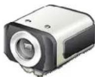
VCC-HD2300/HD2300P
VCC-HD2100/HD2100P
Chapter 7
Copyright Notice/How to Use This Manual
Copyright Notice
How to use this manual
Copyright Notice
This instruction manual is copyrighted by SANYO Electric Co., Ltd. No materials contained in this manual may be reproduced in any format without the prior permission of the copyright holder.
Microsoft, Windows, ActiveX and Internet Explorer are registered trademarks or trademarks of Microsoft Corporation in the United States and other countries.
The official name for "Windows" used in this manual is Microsoft® Windows® Operating System.
In this manual, note that the word "Windows" refers to both "Microsoft® Windows® XP Operating System" and "Microsoft® Windows® Vista Operating System".
Intel and Pentium are registered trademarks or trademarks of Intel Corporation and its subsidiaries in the United States and other countries.
IBM and IBM PC/AT are trademarks of International Business Machines Corporation.
HDMI, the HDMI Logo and High-Definition Multimedia Interface are trademarks or registered trademarks of HDMI Licensing LLC.
All other brands and product names in this manual are the registered trademarks or trademarks of their respective owners.
OpenSSL License
The following license is applied to OpenSSL.
LICENSE ISSUES
The OpenSSL toolkit stays under a dual license, i.e. both the conditions of the OpenSSL License and the original SSLeay license apply to the toolkit. See below for the actual license texts. Actually both licenses are BSD-style Open Source licenses. In case of any license issues related to OpenSSL please contact openssl-core@openssl.org.
OpenSSL License
/*
* Copyright (c) 1998-2008 The OpenSSL Project. All rights reserved.
* Redistribution and use in source and binary forms, with or without * modification, are permitted provided that the following conditions * are met:
* 1. Redistributions of source code must retain the above copyright * notice, this list of conditions and the following disclaimer.
* 2. Redistributions in binary form must reproduce the above copyright * notice, this list of conditions and the following disclaimer in * the documentation and/or other materials provided with the * distribution.
* 3. All advertising materials mentioning features or use of this * software must display the following acknowledgment:
* "This product includes software developed by the OpenSSL Project * for use in the OpenSSL Toolkit. (http://www.openssl.org/)
* 4. The names "OpenSSL Toolkit" and "OpenSSL Project" must not be used to * endorse or promote products derived from this software without * prior written permission. For written permission, please contact * openssl-core@openssl.org.
* 5. Products derived from this software may not be called "OpenSSL"
* nor may "OpenSSL" appear in their names without prior written
* permission of the OpenSSL Project.
*
* 6. Redistributions of any form whatsoever must retain the following
* acknowledgment:
* "This product includes software developed by the OpenSSL Project
* for use in the OpenSSL Toolkit (http://www.openssl.org/)
*
* THIS SOFTWARE IS PROVIDED BY THE OpenSSL PROJECT ``AS IS'' AND ANY
* EXPRESSED OR IMPLIED WARRANTIES, INCLUDING, BUT NOT LIMITED TO, THE
* IMPLIED WARRANTIES OF MERCHANTABILITY AND FITNESS FOR A PARTICULAR
* PURPOSE ARE DISCLAIMED. IN NO EVENT SHALL THE OpenSSL PROJECT OR
* ITS CONTRIBUTORS BE LIABLE FOR ANY DIRECT, INDIRECT, INCIDENTAL,
* SPECIAL, EXEMPLARY, OR CONSEQUENTIAL DAMAGES (INCLUDING, BUT
* NOT LIMITED TO, PROCUREMENT OF SUBSTITUTE GOODS OR SERVICES;
* LOSS OF USE, DATA, OR PROFITS; OR BUSINESS INTERRUPTION)
* HOWEVER CAUSED AND ON ANY THEORY OF LIABILITY, WHETHER IN CONTRACT,
* STRICT LIABILITY, OR TORT (INCLUDING NEGLIGENCE OR OTHERWISE)
* ARISING IN ANY WAY OUT OF THE USE OF THIS SOFTWARE, EVEN IF ADVISED
* OF THE POSSIBILITY OF SUCH DAMAGE.
* ____
*
* This product includes cryptographic software written by Eric Young
* (eay@cryptsoft.com). This product includes software written by Tim
* Hudson (tjh@cryptsoft.com).
*
* /
Original SSLeay License
/* Copyright (C) 1995-1998 Eric Young (eay@cryptsoft.com)
* All rights reserved.
*
* This package is an SSL implementation written
* by Eric Young (eay@cryptsoft.com).
* The implementation was written so as to conform with Netscapes SSL.
*
* This library is free for commercial and non-commercial use as long as
* the following conditions are aheared to. The following conditions
* apply to all code found in this distribution, be it the RC4, RSA,
* lhash, DES, etc., code; not just the SSL code. The SSL documentation
* included with this distribution is covered by the same copyright terms
* except that the holder is Tim Hudson (tjh@cryptsoft.com).
*
* Copyright remains Eric Young's, and as such any Copyright notices in
* the code are not to be removed.
* If this package is used in a product, Eric Young should be given attribution
* as the author of the parts of the library used.
* This can be in the form of a textual message at program startup or
* in documentation (online or textual) provided with the package.
*
* Redistribution and use in source and binary forms, with or without
* modification, are permitted provided that the following conditions
* are met:
* 1. Redistributions of source code must retain the copyright
* notice, this list of conditions and the following disclaimer.
* 2. Redistributions in binary form must reproduce the above copyright
* notice, this list of conditions and the following disclaimer in the
* documentation and/or other materials provided with the distribution.
* 3. All advertising materials mentioning features or use of this software
* must display the following acknowledgement:
* "This product includes cryptographic software written by
* Eric Young (eay@cryptsoft.com)"
* The word 'cryptographic' can be left out if the rouines from the library
* being used are not cryptographic related :-).
* 4. If you include any Windows specific code (or a derivative thereof) from
* the apps directory (application code) you must include an acknowledgement:
* "This product includes software written by Tim Hudson (tjh@cryptsoft.com)"
*
* THIS SOFTWARE IS PROVIDED BY ERIC YOUNG ``AS IS'' AND
* ANY EXPRESS OR IMPLIED WARRANTIES, INCLUDING, BUT NOT LIMITED TO, THE
* IMPLIED WARRANTIES OF MERCHANTABILITY AND FITNESS FOR A PARTICULAR PURPOSE
* ARE DISCLAIMED. IN NO EVENT SHALL THE AUTHOR OR CONTRIBUTORS BE LIABLE
* FOR ANY DIRECT, INDIRECT, INCIDENTAL, SPECIAL, EXEMPLARY, OR CONSEQUENTIAL
* DAMAGES (INCLUDING, BUT NOT LIMITED TO, PROCUREMENT OF SUBSTITUTE GOODS
* OR SERVICES; LOSS OF USE, DATA, OR PROFITS; OR BUSINESS INTERRUPTION)
* HOWEVER CAUSED AND ON ANY THEORY OF LIABILITY, WHETHER IN CONTRACT, STRICT
* LIABILITY, OR TORT (INCLUDING NEGLIGENCE OR OTHERWISE) ARISING IN ANY WAY
* OUT OF THE USE OF THIS SOFTWARE, EVEN IF ADVISED OF THE POSSIBILITY OF
* SUCH DAMAGE.
*
* The licence and distribution terms for any publicly available version or
* derivative of this code cannot be changed. i.e. this code cannot simply be
* copied and put under another distribution licence
* [including the GNU Public Licence.]
* /
How to use this manual
Window Layout
This manual consists of three resident windows:
text_image
1 2 3 Registers the user 1 2 3 4 5 6 7 8 9 10 11 12 13 14 15 16 17 18 19 20 21 22 23 24 25 26 27 28 29 30 31 32 33 34 35 36 37 38 39 40 41 42 43 44 45 46 47 48 49 50 51 52 53 54 55 56 57 58 59 60 61 62 63 64 65 66 67 68 69 70 71 72 73 74 75 76 77 78 79 80 81 82 83 84 85 86 87 88 89 90 91 92 93 94 95 96 97 98 99 1001INDEX window
This window shows a table of contents.
The headline of the topic currently opened at the main window is highlighted, so the current location among the manual can be easily confirmed.
2TITLE window
This window shows the headline of the current topic. This TITLE window never scrolls not to hide the headline.
3MAIN window
This window shows the main detail contents.
Navigation
text_image
Searches videos. 1 2 3 4 5 6 7 8 9 10 11 12 13 14 15 16 17 18 19 20 21 22 23 24 25 26 27 28 29 30 31 32 33 34 35 36 37 38 39 40 41 42 43 44 45 46 47 48 49 50 51 52 53 54 55 56 57 58 59 60 61 62 63 64 65 66 67 68 69 70 71 72 73 74 75 76 77 78 79 80 81 82 83 84 85 86 87 88 89 90 91 92 93 94 95 96 97 98 99 1001Previous/Next
Clicking
2Page end

is located at the end of the page.
This mark is also linked to the top of the page. Click on this mark to jump to the top of the page.
Conventions
text_image
gisters the user. User Registration User ID Password Password(Verify) Change Add Cancel Advanced Setup One One User The user user is set to the [User ID] (for 1) Where you register multiple users, copy or edit 1 to 6. Requesting a new user with all of another operating privileges to the defaults. To change the opening privilege of each user, select the user in the [User ID] (or any other) or the [Registered Setup] where The User Registration Service is required. One One User One (20%) to complete the registration and select the [User Registration] service. This information which can be used for the user (I) and password use other (L), saved (S), about (O) and update (R)
text_image
Bar Functions and Following table lists the functions you Playback, Camera Control, or Menu Set The operating privileges for each user ca 1 Network Recorder(Client) File Edit View Playback Record O Menu Sub M Print Off • Copy • Printbox • Document • Printout • Print (Edit) • Print (Edit) • Print (Edit) • Print (Edit) • Print (Edit) • Print (Edit) • Print (Edit) • Print (Edit) • Print (Edit) • Print (Edit) • Print (Edit) • Print (Edit) • Print (Edit) • Print (Edit) • Print (Edit) • Print (Edit) • Print (Edit) • Print (Edit) • Print (Edit) • Print (Edit) • Print (Edit)Numbers
123 ...
Boxed numbers indicate procedural instructions.
1 2 3 ... A B C ...
Circled numbers or circled alphabetic letters are used in sections that describe screen component names or other information.
Symbols
This manual uses the following three kinds of symbols depending on the content of the provided information.

Memo:
Indicates supplementary or related information.

Reference:
Provides references to the associated settings that must be configured on other menu screens.

Caution:
Indicates prohibited or restricted operating and setting instructions.
Uppercase Letters, Graphics, and Punctuation Marks
This manual uses the following notations to present user-interface related information:
Information such as the screen title is represented in all uppercase alphabetic letters, as displayed on the screen (Example: NETWORK SETTINGS).
Information such as operation buttons and icons are represented as graphics, as displayed on the screen (Example: SET).
The names of specific setting items, tabs, dialog boxes and the like are enclosed in square brackets [ ] (Example: [TITLE]).
The options or values that you select in a pull-down menu or using radio buttons are enclosed in double quotes “” (Example: “ON”, “80”).
Screenshots
Each section describing a configuration procedure begins with a screenshot of the corresponding initial configuration screen.
The purpose of this screenshot is to show you the factory default value for each setting item provided on the screen.