TK-T8101WPRU - Security Camera JVC - Free user manual and instructions
Find the device manual for free TK-T8101WPRU JVC in PDF.

| Product Type | Security Camera (IR Bullet Camera) |
| Brand | JVC |
| Model | TK-T8101WPRU |
| Image Sensor | 1/3 type IT CCD |
| Signal System | NTSC / PAL (selectable) |
| Effective Pixels | 976 (H) x 494 (V) (NTSC) / 976 (H) x 582 (V) (PAL) |
| Horizontal Resolution | 600 TV lines |
| Lens | F1.4, f:3.3 ~ 12mm (varifocal) |
| Angle of View | Wide: 89.8° (H), 63.6° (V); Tele: 23.9° (H), 17.9° (V) |
| Minimum Illumination | 0 lx (IR LED ON); Color/B&W switch point 20 lx |
| IR Distance | 20 m |
| IR Wavelength | 850 nm |
| Video Output | 1 Vp-p composite, 75 Ω |
| S/N Ratio | 50 dB typ. (AGC off) |
| Synchronization | Internal |
| Power Supply | DC 12V or AC 24V (±10%), 50/60 Hz |
| Power Consumption | DC12V: 580 mA |
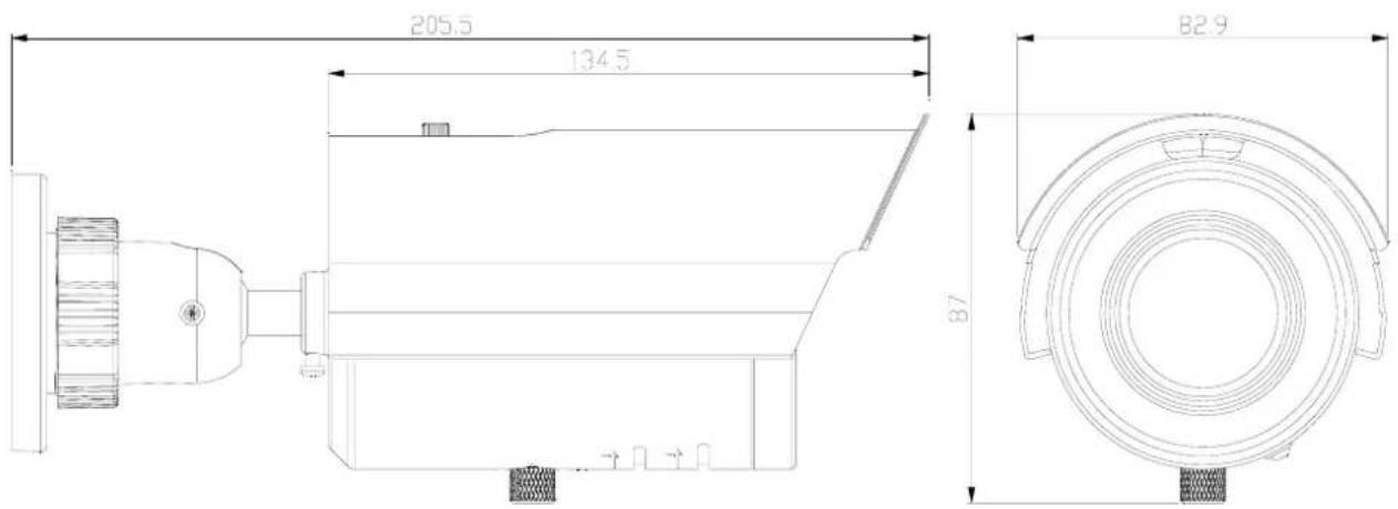
| Dimensions (W x D x H) | 87 mm x 83 mm x 205.5 mm |
| Weight | Approx. 680 g |
| Operating Temperature | -10°C to 50°C |
| Storage Temperature | -20°C to 60°C |
| OSD Menu | Yes (joystick control) |
| Day/Night Mode | Auto switching (Color/B&W) |
| Motion Detection | Yes (up to 4 areas) |
| Privacy Masking | Yes (up to 8 zones) |
| Digital Noise Reduction | Yes (Y/C adjustable) |
| Backlight Compensation | BLC / HLC |
| White Balance | ATW, Push, Manual, etc. |
| Lens Type | DC Iris (Auto or Manual) |
| Mount Type | Bracket with safety wire provision |
| Weatherproof | Indoor use (not rated for outdoor exposure) |
| Cleaning | Soft dry cloth; mild detergent if needed |
| Safety | Use CSA/UL Class 2 power adapter; follow local codes |
| Included Accessories | Camera, manual, warranty card, template, screws, anchors, OSD joystick, caution card, safety precautions sheet |
Frequently Asked Questions - TK-T8101WPRU JVC
User questions about TK-T8101WPRU JVC
0 question about this device. Answer the ones you know or ask your own.
Ask a new question about this device
Download the instructions for your Security Camera in PDF format for free! Find your manual TK-T8101WPRU - JVC and take your electronic device back in hand. On this page are published all the documents necessary for the use of your device. TK-T8101WPRU by JVC.
USER MANUAL TK-T8101WPRU JVC
natural_image
3D rendering of a metallic security camera with green lens (no text or symbols visible)Important Safety Information
Before attempting to connect or operate this product, please read these instructions carefully and save this manual for future use.
Important Safety Information
Warning and Operating Notes
Installation and serving the camera should be performed only by qualified and experienced technicians to conform to all local codes and to maintain your warranty.
WARNING! The use of CSA certified/UL Listed Class 2 power adapters are required to ensure compliance.
Note:
This product is intended to be supplied by a Listed Direct Plug-In Power Unit marked "Class 2" or Listed Adapter marked "L.P.S." (or "Limited Power Source") and rated output DC 12V, 0.58A minimum or AC 24V, 60Hz, 0.58A minimum. (for USA)
WARNING! To reduce the risk of fire or electric shock, do not expose the product to rain or moisture.
| Caution | Connect only one camera to the power line, AC24V/DC12V.Do not share the power line with other equipment. The power cable between power source and the camera must be under 3 m. |
Operating Notes
Power Supply: This bullet camera can operate on AC 24V or DC 12V.
| Note | Connectors and field wiring terminals for external Class 2 circuits provided with marking indicating minimum Class of wiring to be used. Class 2 shall be marked adjacent to the field wiring terminals. |
Operating Conditions
- Avoid viewing very bright objects (example, light fixtures) for extended periods.
-
Avoid operating or storing the unit in the following locations:
-
Extremely humid, dusty, hot, cold environments (where the operating temperature is outside the recommended range of 14^ to 122^ [-10^ to +50^] .)
- Close to sources of powerful radio or TV transmitters
- Close to fluorescent lamps or objects reflecting light
- Under unstable light sources (may cause flickering)
CONTENTS
1. Instructions 4
1.1 Before You Begin 4
1.2 Dimensions 4
1.3 Names of Camera Parts 5
1.4 Routine Maintenance 6
2 Installation 7
2.1 Mounting the Camera....7
3. OSD Settings....10
3.1 Lens 10
3.2 SHUTTER/AGC 10
3.3 WHITE BAL....11
3.4 BACKLIGHT....11
3.5 PICTURE ADJUST 12
3.6 ATR 12
3.7 MOTION DET....12
3.8 PRIVACY 12
3.9 DAYNIGHT 13
3.10 NR....13
3.11 CAMERA ID 13
3.12 LANGUAGE 13
3.13 CAMERA RESET 13
3.14 SAVE ALL 13
4. Specification 14
Introductions
1. Instructions
The IR Bullet camera is ideal for indoor installation in commercial and residential environment.
1.1 Before You Begin
Please read this guide carefully before you install the bullet camera. Keep this guide for future reference.
1.2 Dimensions
Part Names and Locations
1.3 Names of Camera Parts
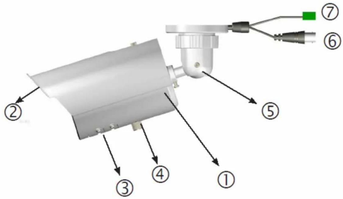
Figure 2-1
- Camera main body
- Sun shield: Minimize the effects of rain and sunlight on image quality.
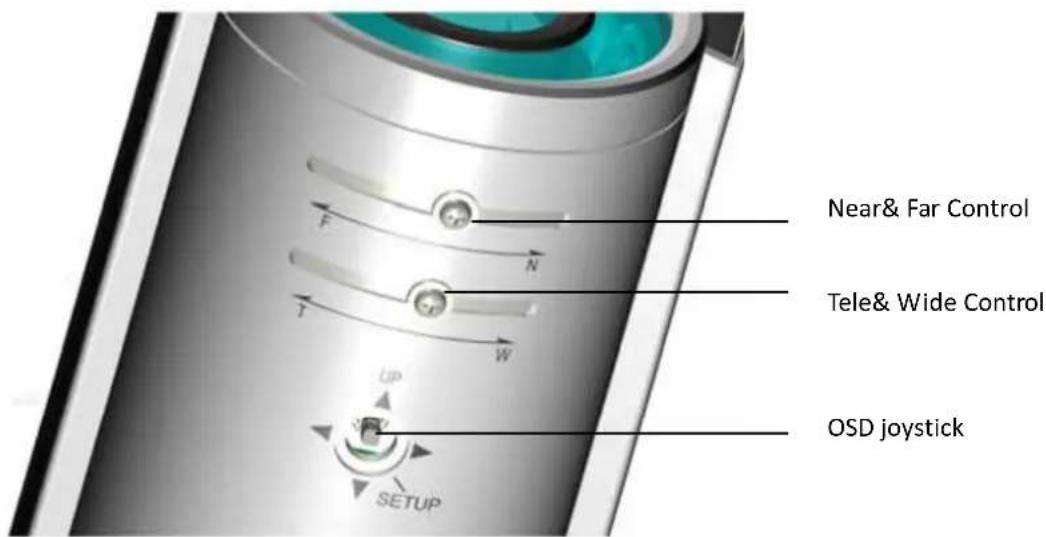
- Externally adjustable focal length & focus
- OSD menu joystick:
To use the OSD joystick control:
- Press the OSD joystick control straight down to enter the Main menu or a selected item.
-
Move the OSD joystick control UP, DOWN, LEFT and RIGHT to navigate through menus and options.
-
Mount bracket: Connects to the Mount.
- BNC connector: Connects to the VIDEO IN connector of the Monitor Video Connector
- Power connector: Connects to the external power source. DC12V/AC24V (Please refer to camera label)
Part Names and Locations
1.4 Routine Maintenance
- Use a soft, dry cloth to remove any fingerprints or dust.
- Clean the camera housing with a soft, dry cloth. For more stubborn stains, use a cloth dampened with a small quantity of neutral detergent, then wipe dry.
Caution: Do not use volatile solvents such as alcohol, benzene or thinners to avoid damaging the surface finish.
2 Installation
2.1 Mounting the Camera
Step 1: Drill mounting holes and insert anchors.
In desired location, use the supplied Guide Pattern to drill three 5mm mounting holes. Then insert the supplied anchors into the holes.
To prevent the camera from falling off, ensures it is connected to a firm place (ceiling slab or channel) using a Safety Wire (fall prevention wire is not supplied).

Installation
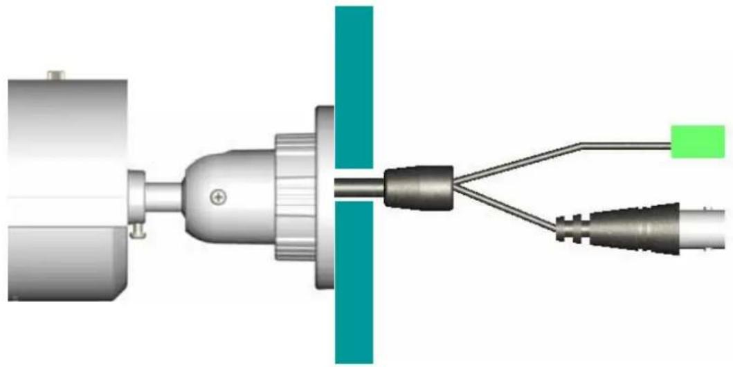
Step 2: Pass all the signal cables through the hole for the cables.
Optionally connect a video monitor to the BNC connector if you want to perform focus/zoom adjustments during the installation.
natural_image
Diagram of a mechanical or electrical connector assembly with two connected wires and a central shaft (no text or symbols visible)Step 3: For static electricity protection, ensure that the rubber pad is placed inside the mounting bracket base.
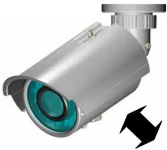
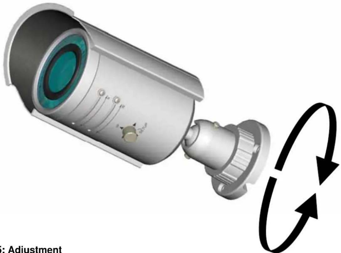
Step 4: Modify the position of camera
Loosen the two screws (left and right) first (just rotate slightly one circle or the screws will fall down), second, rotate the Retaining ring then you will be able to hold the camera and adjust its angle. Fasten the screws and retaining ring to ensure the desired angle.
natural_image
3D rendering of a metallic security camera with a green lens and black directional arrow (no text or symbols)Installation
natural_image
3D illustration of a security camera with adjustment mechanism shown in circular arrows (no text or symbols on the device itself)Step 5: Adjustment
It can be adjusted once the screw is fully loosened. After adjustment, be sure to lock it tightly for waterproof.
Notice: Please be careful when adjusting Tele/Wide and Near/Far so as to avoid damage to the lens
Step 6: Place the three provided insulation caps onto the three tapping screws.
Insert the screws to the screw holes on the camera bracket, and then tighten the screws to the anchors to attach the camera..
3. OSD Settings
Use the OSD menu to set up the camera for optimum performance
| LENS | AUTO |
| SHUTTER/AGC | AUTO |
| WHITE BAL | ATW |
| BACKLIGHT | OFF |
| PICT ADJUST | |
| ATR | OFF |
| MOTION DET | OFF |
| NEXT | |
| EXIT | SAVE ALL |
| PRIVACY | OFF |
| DAY/NIGHT | AUTO |
| NR | |
| CAMERA ID | OFF |
| SYNC | INT |
| LANGUAGE | ENGLISH |
| CAMERA RESET | |
| BACK | |
| EXIT | SAVE ALL |
Figure 3-1 Main menu
3.1 Lens
The LENS settings allow you to configure Lens and brightness. Options are AUTO (Auto Iris lens) and MANUAL. The default setting is AUTO.
In the AUTO submenu, you can set the MODE as OPEN, CLOSE or AUTO. Then select SPEED to adjust the DC Iris Lens convergence speed.
| TYPE | DC |
| MODE | OPEN |
| SPEED | 046 |
| RETURN |
3.2 SHUTTER/AGC
You can set the SHUTTER/AGC as AUTO or MANUAL. The default setting is AUTO.
When LENS is set to AUTO: It is recommended to set SHUTTER/AGC to AUTO mode. In the AUTO submenu, adjust HIGH LUMINANCE MODE according to your application:
- AUTO IRIS mode: Use this for normal condition application environments. The IRIS level will be controlled by camera brightness.
- SHUT+AUTO IRIS mode: Use this for high light application environments. The exposure will be controlled by AES or the DC Iris. The iris level will be controlled by camera brightness.
| HIGH LUMINANCE | |
| MODE | AUTO IRIS |
| BRIGHTNESS | 024 |
| LOW LUMINANCE | |
| MODE | AGC |
| BRIGHTNESS | × 0.25 |
| RETURN | |
Menu Settings
If SHUTTER/AGC is set to MANUAL, the submenu is shown as below. The shutter speed is a variable from 1/50(1/60) sec to 1/10000sec and the AGC is selectable depending on your environment condition.
| MODE | SHUT+AGC |
| SHUTTER | 1/50 |
| AGC | 6.0 |
| RETURN |
Recommended settings according to the application:
- Auto Exposure by Iris Control:
Application: General Purpose, Indoor surveillance
This is Default settings
- LENS: AUTO
- SHUTTER/AGC: AUTO
-
HIGH LUMINANCE MODE: AUTO IRIS
-
Auto Exposure by AES first, then by IRIS Control:
Application: Outdoor, Traffic surveillance
- LENS: AUTO
- SHUTTER/AGC: AUTO
-HIGH LUMINANCE MODE: SHUT + AUTO IRIS
-
Auto Exposure by Iris Control with fixed Shutter Speed:
-
LENS: AUTO
- SHUTTER/AGC: MANUAL
-SHUTTER 1/50 (1/60) \~10000
(After this, the following are set)
- SHUTTER/AGC: AUTO
- HIGH LUMINANCE MODE: SHUT+AUTOIRIS
3.3 WHITE BAL
WHITE BALANCE controls color on the screen. Options include ATW (Auto White Balance), PUSH, PUSH LOCK, USER1, USER2, ANTI CR (Anti Color Rolling Suppression) and MANUAL. The default is ATW.
- ATW: Select ATW when the scene illumination varies between indoor scenes and outdoor scene lighting.
| SPEED | 171 |
| DELAY CNT | 152 |
| ATW FRAME | × 0.50 |
| ENVIRONMENT | INDOOR |
| RETURN |
- MANUAL: You can manually adjust the LEVEL from 15 to 69.
- USER1/USER2: You can adjust blue setting (B-GAIN) and red setting (R-GAIN) value from 0 to 255.
- PUSH: When selected in the appropriate position, the whole area will perform white balance.
- PUSH LOCK: When selected in the appropriate position, WHITE BALANCE will perform once.
3.4 BACKLIGHT
Set Backlight compensation function. It controls the light level to overcome sever backlight conditions.
Available options include OFF, BLC or HLC (Highlight Compensation) mode. The default is OFF.
If HLC is selected, HLC is activated automatically when the camera detects high-luminance.
3.5 PICTURE ADJUST
PICTURE ADJUST allows you to adjust picture settings for optimal image. In the PICT ADJUST submenu, you can adjust BRIGHTNESS, CONTRAST, SHARPNESS, HUE and GAIN value. In addition, you can set MIRROR to ON to reflect the image.
| MIRROR | OFF |
| BRIGHTNESS | 000 |
| CONTRAST | 128 |
| SHARPNESS | 128 |
| HUE | 128 |
| GAIN | 128 |
| RETURN |
3.6 ATR
Set ATR (Adaptive Tone-curve Reproduction) function. You can select ON or OFF. The default is OFF. If selecting ON, you will enter the ATR submenu, where you can set LUMINACE and CONTRAST to optimize by image.
| LUMINANCE | LOW |
| CONTRAST | LOW |
| RETURN |
*Also known as Wide Dynamic Range. This function expands the video dynamic range of the camera and improves visibility of images even in high contrast environments.
3.7 MOTION DET
MOTION DET allows to detect moving objects on the screen. The default is OFF. If selecting ON, you will enter the MOTION DET submenu. You can set up to 4 motion areas to detect moving objectives and adjust the motion detection sensitivity from 0 to 127.
3.8 PRIVACY
PRIVACY function mask up to 8 privacy areas on the screen from video monitoring. The default setting is OFF. If selecting ON, you will enter the PRIVACY submenu. You can configure up to 8 privacy areas and set color and transparency of the privacy zones. In addition, you can enable MOSAIC function for the privacy zone.
Note: If you enable MOTION DET function, then PRIVACY function will support 4 zones only.
| REA SEL | 1/8 |
| TOP | 000 |
| BOTTOM | 000 |
| LEFT | 000 |
| RIGHT | 000 |
| COLOR | 1 |
| TRANSP | 0.00 |
| MOSAIC | OFF |
| RETURN |
3.9 DAY/NIGHT
The camera will automatically switch to B/W mode when the illumination is under a certain threshold. There is no need to adjust this setting.
Under B/W mode, you can set BURST to be ON or OFF.
3.10 NR
NR allows you to configure the DNR (Digital Noise Reduction) settings to reduce noise on the screen. In the NR submenu, you can enable the NR MODE to the Y (BRIGHT) / C (COLOR), C LEVEL or Y LEVEL mode. According to your NR mode, you can adjust Y LEVEL or C LEVEL as required.
| NR MODE | Y/C |
| Y LEVEL | 000 |
| C LEVEL | 000 |
| RETURN |
Note: When the Y Level is higher the noise in dark areas becomes lessened. Also, resolution will become lower. When it is lower, there is more noise in dark areas.
3.11 CAMERA ID
CAMERA ID displays ON or OFF. The default setting is OFF. You can set the ON mode to add a camera title up to 26 characters with 2 lines and also select where the title appears on the monitor screen.
3.12 LANGUAGE
OSD supports 8 multiple languages. Options include ENGLISH (default), JAPANESE, GERMAN, FRENCH, RUSSIAN, PORTUGUESE, SPANISH and SIMPLIFIED CHINESE.
3.13 CAMERA RESET
To restore factory defaults, select CAMERA RESET and then press the joystick control.
3.14 SAVE ALL
SAVE ALL items allows you to save all settings and exit the OSD menu.
4. Specification
| Signal System NTSC PAL | ||
| Image System | ||
| Imager Size 1/3 type: IT CCD | ||
| Effective pixels?「HxV?」 | 976 (H) × 494 (V) 976 (H) × 582 | (V) |
| Optical system | ||
| Lens F1.4, f:3.3 ~ 12mm | ||
| Angle of View | Wide: 89.8°(H), 63.6°(V)Tele: 23.9°(H),17.9°(V) | |
| Electrical Specification | ||
| TV System 2:1 Interlace | ||
| Horizontal Resolution 600 TV lines | ||
| S/N Ratio 50dB typ. (AGC off) | ||
| Minimum Illumination | IR LED ON 0 lx (Color/B&W switch point 20lx typ.) | |
| Synchronization System Internal | ||
| Video Output 1V | pp composite output, 75Ω | |
| IR Distance | 20 | |
| IR wavelength 850nm | < | |
| Mechanical | ||
| Dimension 83mm(D)x87(W)x205.5mm(H) | ||
| Weight | 680g approx. | |
| Power Supply | ||
| Input Voltage | DC 12V & AC 24V (50Hz/60Hz) ±10% | |
| Power Consumption | DC12V 580mA | |
| Environmental | ||
| Operating Temperature | -10°C ~ 50°C | |
| Operating Humidity | 90% MAX | |
| Storage Temperature | -20°C ~ 60°C | |
| Storage Humidity | 90% MAX | |
| Safety Regulation | ||
| FCC | FCC Class B | |
| CE | CE Class B | |
| Accessories | IR BULLET CAMERA X 1 | IR BULLET CAMERA X 1 |
| INSTRUCTIONS X 1 | INSTRUCTIONS X 1 | |
| SAFETY PRECAUTIONS X 1 | SAFETY PRECAUTIONS X 1 | |
| WARRANTY CARD X 1 | CAUTION CARD X 1 | |
| CAUTION CARD X 1 | TEMPLATE X 1 | |
| TEMPLATE X 1 | WASHER X 3 | |
| WASHER X 3 | SCREW X 3 | |
| SCREW X 3 | SCREW ANCHOR X 3 | |
| SCREW ANCHOR X 3 | OSD JOYSTICK X 1 | |
| OSD JOYSTICK X 1 | ||