HPA1302 - Receiver Atlas Sound - Free user manual and instructions
Find the device manual for free HPA1302 Atlas Sound in PDF.


User questions about HPA1302 Atlas Sound
0 question about this device. Answer the ones you know or ask your own.
Ask a new question about this device
Download the instructions for your Receiver in PDF format for free! Find your manual HPA1302 - Atlas Sound and take your electronic device back in hand. On this page are published all the documents necessary for the use of your device. HPA1302 by Atlas Sound.
USER MANUAL HPA1302 Atlas Sound
text_image
Atlas IEDHPA602 / HPA1302
Multi-Impedance High Power Amplifiers

text_image
Class D TOPOLGY Protect Limit Signal Ready 1 2 Power Temp Standby Atlas Sound HPA602 Multi-Impedance Amplifier
text_image
Class D TOPOLOST Protect Limit Signal Ready Power Temp Standles Atlas Sound HPA1302 Multi-Impedance Amplifier
Atlas
IED.
1601 Jack McKay Blvd. • Ennis, Texas 75119 U.S.A.
Telephone: 800.876.3333 • Fax: 800.765.3435
- 1 - AtlasIED.com
Table of Contents
Important Safety Instructions....3
Introduction 5
Key Features.... 5
Front Panel Description 6
Tamper Proof Security Cover 6
Rear Panel Description 8
Bridge Mode Operation....9
Remote Turn On 10
Placement of the Amp 12
Cabling....12
Connecting the HPA Amplifier to AC Mains.... 13
Optional Dante™ Input Card 14
Specifications 15
Warranty 20
Important Safety Instructions


WARNING: SHOCK HAZARD - DO NOT OPEN AVIS: RISQUE DE CHOC ELÉCTRIQUE - NE PAS OUVRIR
WARNING: TO REDUCE THE RISK OF FIRE OR ELECTRIC SHOCK DO NOT EXPOSE THIS EQUIPMENT TO RAIN OR MOISTURE
AVIS: NE PAS EXPOSER CE MATÉRIEL À LA PLUIE OU L'HUMIDITE AFIN DE REDUIRE LE RISQUE D'INFLAMMATION OU DE CHOC ÉLÉCTRIQUE

The lightning flash with arrowhead symbol within an equilateral triangle, is intended to alert the user to the presence of uninsulated "dangerous voltage" within the product's enclosure that may be of sufficient magnitude to constitute a risk of electric shock to persons.

The exclamation point within an equilateral triangle is intended to alert the user to the presence of important operating and maintenance (servicing) instructions in the literature accompanying the product.
- Read these instructions.
- Keep these instructions.
- Heed all warnings.
- Follow all instructions.
- Do not use this device near water.
- Clean only with dry cloth.
- Do not block any ventilation openings. Install in accordance with the manufacturer's instructions.
- Do not install near any heat sources such as radiators, heat registers, stoves, or other device that produce heat.
- Do not defeat the safety purpose of the polarized or grounding-type plug. A polarized plug has two blades with one wider than the other. A grounding type plug has two blades and a third grounding prong. The wide blade or the third prong are provided for your safety. If the provided plug does not fit into your outlet, consult an electrician for replacement of the obsolete outlet.
- Protect the power cord from being walked on or pinched particularly at plugs, convenience receptacles, and the point where they exit from the device.
- Only use attachments/accessories specified by the manufacturer.
- Use only with the cart, stand, tripod, bracket, or table specified by the manufacturer, or sold with the device. When a cart is used, use caution when moving the cart / device combination to avoid injury from tip-over.

- Unplug this device during lightning storms or when unused for long periods of time.
- Refer all servicing to qualified service personnel. Servicing is required when the device has been damaged in any way, such as power-supply cord or plug is damaged, liquid has been spilled, or objects have fallen into the device, the device has been exposed to rain or moisture, does not operate normally, or has been dropped.
- This product is equipped with a three-wire grounding-type plug, a plug having a third (grounding) pin. This plug will only fit into a grounding-type power outlet. This is a safety feature. If you are unable to insert the plug into the outlet, contact your electrician to replace your obsolete outlet. Do not defeat the safety purpose of the grounding-type plug.
- WARNING: To reduce the risk of fire or electric shock, this device should not be exposed to rain or moisture and objects filled with liquids, such as a vase, should not be placed on this device.
- To completely disconnect this equipment from the mains, disconnect the power supply cord plug from the receptacle.
- The mains plug of the power supply cord shall remain readily operable.
- Protective earthing terminal. The apparatus should be connected to a mains socket with a protective earthing connection.
Atlas IED
1601 Jack McKay Blvd. • Ennis, Texas 75119 U.S.A.
Telephone: 800.876.3333 • Fax: 800.765.3435
- 3 - AtlasIED.com

WARNING - When The Device Is In Use
- WARNING: For the terminals marked with symbol of may be of sufficient magnitude to constitute a risk of electric shock. The external wiring connected to the terminals requires installation by an instructed person or the used of ready-made leads or cords.
- WARNING: The apparatus shall not be exposed to dripping or splashing and that objects filled with liquids, such as vases, shall not be placed on apparatus.
- WARNING: The mains plug is used as disconnect device, the disconnect device shall remain readily operable.
- To prevent electric shock, do not remove the product cover as there are high voltage components inside. Refer all servicing to AtlasLED.
- Should any of the following irregularities occur during use, immediately switch off the power, disconnect the power cord from the AC outlet and contact AtlasLED. Do not to attempt to continue operation with the product as this may cause fire or electric shock:
- Smoke or strange smell coming from the unit.
• If the product falls or the case is damaged. - If water or any metallic objects falls into the product.
• If the power supply cord is damaged in any way.
• If the unit is malfunctioning. - Do not insert or drop metallic objects or flammable materials into the ventilation holes of the product's cover, as this may result in electric shock or fire.
- Do not place any containers with liquid or metallic objects on the top of the product. If any liquid spills into the unit, fire or electric shock may result.
- Never operate this product or touch the power supply cord during an electrical storm, electric shock may result.
- Never exceed the power rating on the product when connecting equipment. Fire and/or property damage may result.
• Operate the product only with the voltage specified on the unit. Fire and/or electric shock may result if a higher voltage is used. - Do not modify, kink, or cut the power cord. Do not place the power cord in close proximity to heaters and do not place heavy objects on the power cord, including the product itself, doing so may result in fire or electrical shock.
- Ensure that the safety ground terminal is connected to a proper ground. Never connect the ground to a gas pipe as a catastrophic disaster may result.
- Be sure the installation of the product is stable, avoid slanted surfaces as the product may fall and cause injury or property damage.

TION - When Installing The Product
- Plugging in or unplugging the power cord with wet hands may result in electric shock.
- Never move the unit with the power cord plugged into the wall, as damage to the power cord may result.
- When unplugging the cord from the wall, grasp the plug, NOT the cord.
- Never install this product in humid or dusty locations, nor in direct sunlight, near sources of heat, or in areas where sooty smoke or steam are present. Fire and electric shock may result.
- Keep all sides of the unit at least 3 1/2 away from objects that may obstruct air flow to prevent the unit's internal temperature rise.

TION - When The Product Is In Use
- Never place heavy objects on the product, causing it to fall and/or break, resulting in personal injury and property damage. In addition, the product itself may fall and cause injury and property damage.
- Contact AtlasIED for instructions on cleaning the inside of the unit. Large accumulations of dust inside the unit may result in heat buildup and fire.
- Ensure that the power supply plug is securely plugged into the wall outlet. Never allow dust to accumulate on the power plug or inside the wall outlet.
- When cleaning the unit or the unit is not to be operated for an extended period, unplug the power cord from the wall

1601 Jack McKay Blvd. • Ennis, Texas 75119 U.S.A.
Telephone: 800.876.3333 • Fax: 800.765.3435
Introduction
Thank you for purchasing the AtlasIED HPA Series amplifier. The AtlasIED high power amplifier, "HPA" Series, is designed for use in both commercial 70V/100V distributed systems and professional applications that require amplifiers to handle multiple impedance loads. The HPA is compact and lightweight in comparison to other models delivering similar power levels. The HPA Series features Generation II Class D Output topology that provides great efficiency with the sound quality of a Class AB amplifier. The power supply is a switch mode, global auto sensing design that maintains a stable output during fluctuating power conditions. The power supply and output stage collectively are designed to deliver exceptional dynamic high output voltage and current to virtually any loudspeaker load.
The HPA Series features front panel detente level controls with a security cover, remote turn on, balanced inputs, fault reporting and a rear panel accessory card slot for an optional Dante™ 2-channel digital audio interface. HPA Series amplifiers feature a unique output stage, low resistance direct coupled thermal transfer design that effectively maintains optimal temperature across all loads and output levels. HPA Series amplifiers are also energy efficient and meet Energy Star standards, drawing only 1W of power in standby mode.
Whether the application is a large distributed constant voltage sound system or a high SPL sound reinforcement system, the AtlasLED HPA Series is the answer for high power/cost effective amplification needs.
Key Features
- Two Channels
• 4Ω, 8Ω, & 70.7V Operation
• Balanced Inputs - Dante™ Accessory Card Slot
- Fault Reporting
- Remote Turn On
• Stepped Attenuators with Security Cover - Stereo or Parallel Operation Capability
• Auto Sensing 100V-240V\~ AC Mains Power Supply
• Meets Energy Star Standards 1W Standby Mode
Front Panel
text_image
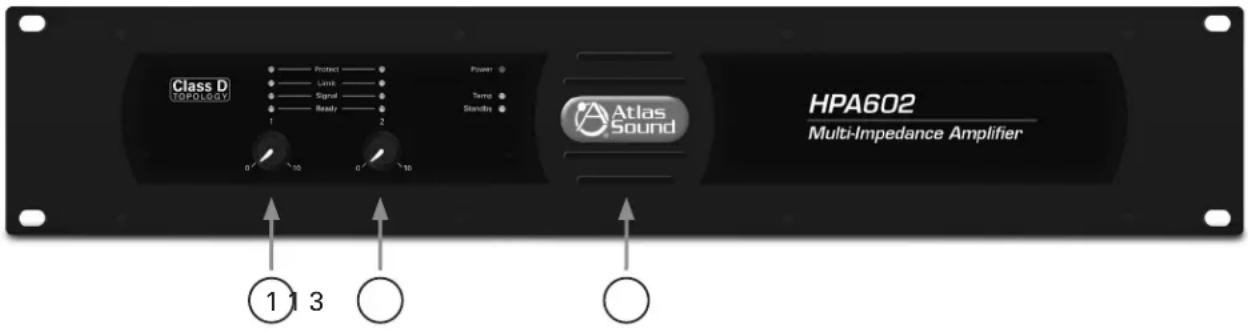
Class D TAPOLATEV Protect Limit Signal Ready Power Temp Standits Atlas Sound HPA602 Multi-Impedance Amplifier 1 3 ① ② ③1. Channel Level Controls
Each channel of the HPA amplifier has an independent detente level control. When either of the potentiometers is turned down (left or FCC - fully counter clockwise) no signal will come out of the corresponding amp channel. When the potentiometer is turned up (right or FC - fully clockwise) the amp will be set for maximum level.
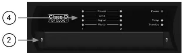
2. Level Control Security Cover
The HPA Series comes with a tamper-proof level control security cover. There are two screws that hold the security cover in place covering all level controls.
text_image
Class D TOPOLOGY 4 1 2 Power Temp Standby3. Air Exhaust
HPA amplifiers have fan assist cooling that draws cool air in from the rear of the amp and exhausts the hot air out the front panel.
4. Status Indicators
A. Power - When AC mains power is applied to the amplifier and the AC Mains Power Switch is in the "ON" position this LED will illuminate blue indicating the amplifier is active and ready for use.
B. Standby - The Standby LED is a bi-color LED giving status of the amplifier power supply.
- Illuminated amber - The HPA Amplifier is in Energy Save Mode and is not ready for use. The rear panel remote activation control port has to be triggered by applying 5-24DC Voltage or shorting the Contact Closure (CC) and ground (GND) pins together to activate the amplifier to ready status. Note: The HPA Amp is shipped with a shunt across the CC and GND contacts to activate the amp from Standby Mode. For the amplifier to be active or On, the Remote Turn On jumper must be in place and the amplifier switch must be in the "On" position. If the Standby LED is not illuminated and the front panel blue LED Power On is illuminated, the amplifier is active and ready to use. Refer to Remote Turn On for more information.
- Illuminated red - If the Standby LED is illuminating red, the AC Mains voltage applied to the HPA Amplifier is out of the safe operating range. The HPA Amplifier cannot be turned on until the AC Mains voltage is between 95V\~ - 264V\~. Refer to AC Mains Input for more information. If the Standby LED is not illuminated and the front panel blue LED Power On is iminated, the amplifier is active and ready to use.
C. Temp - This LED represents the temperature condition of the amplifier. This LED will illuminate yellow once the thermal protection level of any of the amplifier channels or the power supply is reached causing the unit to power off. Note: Also refer to the Protect LED.
Front Panel
D. Ready - The Ready LED will illuminate green when the amplifier channels are stable and ready for use.
E. Signal - The Signal LED will illuminate green when the amplifier output signal produces at least 1-watt output.
F. Limit -The Limit LED will illuminate yellow when the maximum amplifier output level is achieved.
G. Protect -The Protect LED will illuminate red during one the following four conditions. No output will occur while this LED is illuminated. This condition will be reset after the protect condition has been corrected.
- Shorted loudspeaker output.
- Power Supply - If the amplifier exceeds its safe operating temperature, both output channels will be muted with both Protect LEDs illuminated to show the amp is in Protect Mode. The power supply will remain in protect Mode until the temperature returns to a safe operating temperature. Note: The Temp LED will also illuminate during this condition.
- Current Overdrive, if the amplifier channels are driving too low of a loudspeaker load.
- Failure of amp channel, if DC is present at the output the respective amp channel will go into protect.
Rear Panel
HPA602
text_image
AC Motor Audio Sensor 100-2400-2600/80Hz 3200-8A Amplifier Output Class 2 Wiring Optional Accessory Control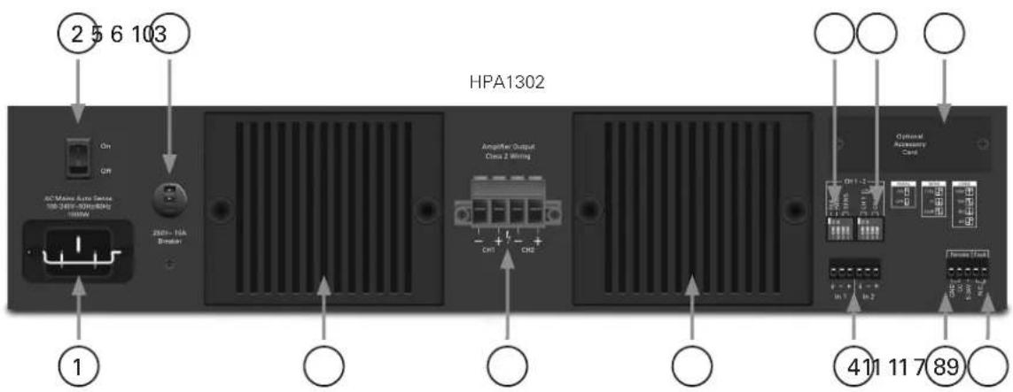
text_image
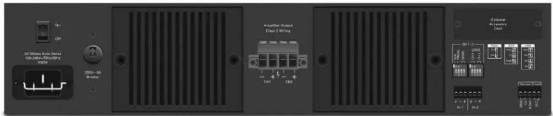
2 5 6 103 HPA1302 On CR AC Motors Auto Sensor 100-248F-300x80Hz 100mA 200+ - 10A Breaker Amperifier Output Class Z Wiring CH1 CH2 ① ④11 11 7 891. AC Mains Input
The HPA602 and HPA1302 feature a global, wide range AC Mains power supply that operates from 100V-240V 50/60Hz power sources. An IEC-60320-C15 receptacle with a retainer clip is provided to make changing the power cord to meet local requirements easier. A 2M 16-gauge power cord is provided with a USD NEMA 5-15 male plug. Insert the IEC power cord into the receptacle making sure it is properly secured using the retainer clip. For non North American applications, refer to local electrical code requirements to select the proper mating power cord.
2. Amplifier Switch
The amplifier switch turns the amplifier power supply from Standby mode to Active On mode. Up is "On" and down is "Off". When on and AC is present the front panel Power LED will illuminate blue. Note: In order for the amplifier to go from Standby mode to Active mode, the amplifier switch must be in the Up (On) position, with either the Contact Closure in place or DC voltage present. The unit is always connected to the mains whether the switch is in the "On" or "Off" position.
3. AC Mains Breaker
If the current drawn from the amplifier is greater than the rating of the AC Mains circuit breaker, the breaker will trip thus shutting the amplifier "Off." Turn the amplifier levels to minimum and reset the breaker to the up position to reset the breaker.
4. Balanced Input
Balanced line level signals connect to the (+) (−) and (G) terminals. Note: If connecting an unbalanced line level input, tie (short) the (G) and (−) terminals together.

Atlas
IED.
1601 Jack McKay Blvd. • Ennis, Texas 75119 U.S.A.
Telephone: 800.876.3333 • Fax: 800.765.3435
AtlasIED.com - 8 -
Rear Panel
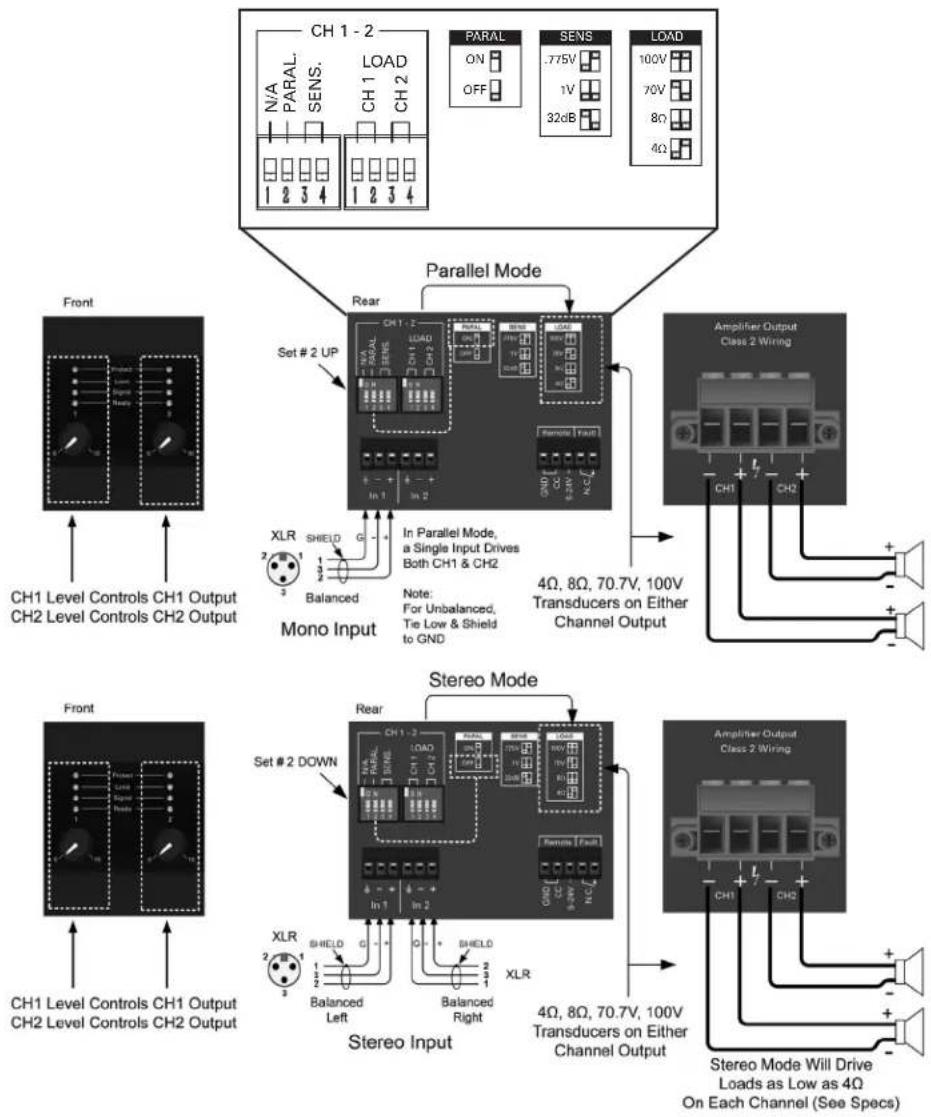
5. Amplifier Sensitivity Select & Parallel Mode Dip Switches
DP SW #1 - N/A = Not Applicable (Not Used)
DP SW #2 - Parallel (Up) = Parallel mode internally combines Inputs 1 & 2 so only one connection is needed to send a signal to Outputs 1 & 2. In parallel mode both amplifier output channels have separate level controls.
DP SW #2 - Stereo (Down) = Stereo mode routes Input 1 to Output 1 and Input 2 to Output 2.
DP SW #3 & #4 - Input Sensitivity, 0.775V, 1V, 32dB. Note: The same setting effects both channels
6. Amplifier Load Configuration Switches
Note: Failure to choose the proper setting to the load applied may cause the amp to go into protect mode.
DP SW #1 & #2 - Load Selection for CH 1 to be 4Ω, 8Ω, 70V, or 100V operation.
DP SW #3 & #4 - Load Selection for CH 2 to be 4Ω, 8Ω, 70V, or 100V operation.
flowchart
graph TD
    subgraph CH1_2
        A["CH1 Level Controls CH1 Output"]
        B["CH2 Level Controls CH2 Output"]
    end

    subgraph CH1_2_Rear
        C["Set # 2 UP"]
        D["In 1"]
        E["In 2"]
        F["Ch1_2"]
        G["Ch2"]
        H["Ch3"]
        I["Ch4"]
        J["Ch5"]
        K["Ch6"]
        L["Ch7"]
        M["Ch8"]
        N["Ch9"]
        O["Ch10"]
        P["Ch11"]
        Q["Ch12"]
        R["Ch13"]
        S["Ch14"]
        T["Ch15"]
        U["Ch16"]
        V["Ch17"]
        W["Ch18"]
        X["Ch19"]
        Y["Ch20"]
    end

    subgraph CH1_2_Rear_Sens
        Z["PARAL ON OFF"]
        AA["SENS .775V 1V 32dB"]
        AB["LOAD 100V 70V 8Ω 4Ω"]
    end

    subgraph CH1_2_Rear_HoA
        AC["Parallel Mode"]
        AD["Monoid Input"]
        AE["Amplifier Output Class 2 Wiring"]
    end

    subgraph CH1_2_Rear_Stereo
        AF["Set # 2 DOWN"]
        AG["Stereo Input"]
        AH["Amplifier Output Class 2 Wiring"]
    end

    subgraph CH1_2_Rear_Land
        AI["XLR SHIELD 1 2 3 Balanced"]
        AJ["XLR SHIELD 1 2 3 Balanced Left"]
        AK["XLR SHIELD 1 2 3 Balanced Right"]
    end

    subgraph CH1_2_Rear_Land_Stereo
        AL["XLR SHIELD 1 2 3 Balanced Left"]
        AM["XLR SHIELD 1 2 3 Balanced Right"]
        AN["XLR SHIELD 1 2 3 Balanced Left"]
        AO["XLR SHIELD 1 2 3 Balanced Right"]
    end

    subgraph CH1_2_Rear_HoA
        AP["XLR SHIELD 1 2 3 Balanced Left"]
        AQ["XLR SHIELD 1 2 3 Balanced Right"]
        AR["XLR SHIELD 1 2 3 Balanced Left"]
        AS["XLR SHIELD 1 2 3 Balanced Right"]
    end

    subgraph CH1_2_Rear_HoA
        AT["XLR SHIELD 1 2 3 Balanced Left"]
        AU["XLR SHIELD 1 2 3 Balanced Right"]
        AV["XLR SHIELD 1 2 3 Balanced Left"]
        AW["XLR SHIELD 1 2 3 Balanced Right"]
    end

    subgraph CH1_2_Rear_Land
        AX["XLR SHIELD 1 2 3 Balanced Left"]
        AY["XLR SHIELD 1 2 3 Balanced Right"]
        AZ["XLR SHIELD 1 2 3 Balanced Left"]
        BA["XLR SHIELD 1 2 3 Balanced Right"]
    end

    subgraph CH1_2_Rear_Land_HoA
        BB["XLR SHIELD 1 2 3 Balanced Left"]
        BC["XLR SHIELD 1 2 3 Balanced Right"]
        BD["XLR SHIELD 1 2 3 Balanced Left"]
        BE["XLR SHIELD 1 2 3 Balanced Right"]
    end

    subgraph CH1_2_Rear_HoA
        BF["XLR SHIELD 1 2 3 Balanced Left"]
        BG["XLR SHIELD 1 2 3 Balanced Right"]
        BH["XLR SHIELD 1 2 3 Balanced Left"]
        BI["XLR SHIELD 1 2 3 Balanced Right"]
    end

    subgraph CH1_2_Rear_Land_HoA
        BJ["XLR SHIELD 1"] --> BK["XLR SHIELD 1"] --> BL["Stereo Input"]
        BM["XLR SHIELD"] --> BN["XLR SHIELD"] --> BO["Stereo Output"]
    end

    subgraph CH1_2_Rear_Land_HoA
        BP["XLR SHIELD"] --> BQ["XLR SHIELD"] --> BR["Stereo Input"]
        BS["XLR SHIELD"] --> BT["XLR SHIELD"] --> BU["Stereo Output"]
    end

    subgraph CH1_2_Rear_HoA
        BV["XLR SHIELD"] --> BW["XLR SHIELD"] --> BX["Stereo Input"]
        BY["XLR SHIELD"] --> BZ["Stereo Output"]
    end

    subgraph CH1_2_Rear_Land_HoA
        BWX["XLR SHIELD"] --> BYX["Stereo Input"]
        BYX --> BZX["Stereo Output"]

    end

Atlas
IED
1601 Jack McKay Blvd. • Ennis, Texas 75119 U.S.A.
Telephone: 800.876.3333 • Fax: 800.765.3435
Rear Panel
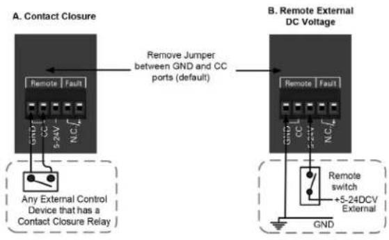
7. Remote Turn ON Terminals
The HPA amplifier can be turned on or activated from a remote location. Note: In order for the amplifier to go from Standby mode to Active mode, the amplifier switch must be in the Up (On) position, with either the Contact Closure in place or DC voltage present. One of these two must be active to turn on the amplifier's power supply. If not, the Standby LED will illuminate amber. Factory shipping default includes a shunt applied across the Ground and CC terminals.
A. Contact Closure - Using a latching contact switch short the Ground and CC ports together.
B. DC Voltage - Applied 5V - 24V DC to these ports.
Remote Activation
text_image
A. Contact Closure Remove Jumper between GND and CC ports (default) B. Remote External DC Voltage Remote Fault CC NC Any External Control Device that has a Contact Closure Relay Remote switch +5-24DCV External GND8. Fault Reporting Terminals
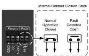
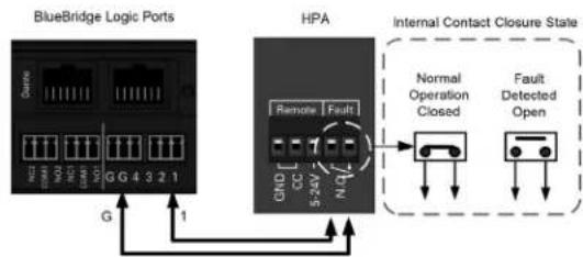
The HPA incorporates a fault reporting system to inform a system administrator if there is something wrong with the amplifier that needs to be attended to by a system technician. The ports are shorted together (NC, Normally Closed) when the amplifier is operating properly. The ports open up under the following conditions indicating there is an issue with the amplifier.
A. Shorted loudspeaker output.
B. Thermal, the temperature of the amplifier channel exceeds its safe operation.
C. Current Overdrive, if the amplifier channels are driving too low of a loudspeaker load.
D. Failure of amp channel, if DC is present at the output the power supply will go into protect.
Fault Reporting
flowchart
graph TD
    A["Remote Fault"] --> B["Normal Operation Closed"]
    C["GND"] --> B
    D["CC"] --> B
    E["5-2A"] --> B
    F["N"] --> B
    B --> G["Fault Detected Open"]
    style A fill:#f9f,stroke:#333
    style C fill:#f9f,stroke:#333
    style D fill:#f9f,stroke:#333
    style E fill:#f9f,stroke:#333
    style F fill:#f9f,stroke:#333
    style B fill:#ccf,stroke:#333
    style G fill:#ccf,stroke:#333
flowchart
graph TD
    A["BlueBridge Logic Ports"] -->|G| B["HPA"]
    B -->|1| A
    B --> C["Internal Contact Closure State"]
    C --> D["Normal Operation Closed"]
    C --> E["Fault Detected Open"]
    style A fill:#f9f,stroke:#333
    style B fill:#ccf,stroke:#333
    style C fill:#cfc,stroke:#333
This example shows the HPA Remote Fault connected to a BlueBridge® Logic port to create an AMP Status Indicator on a Touchscreen.

Atlas
IED
1601 Jack McKay Blvd. • Ennis, Texas 75119 U.S.A.
Telephone: 800.876.3333 • Fax: 800.765.3435
AtlasIED.com - 10 -
Rear Panel
9. Loudspeaker Connections
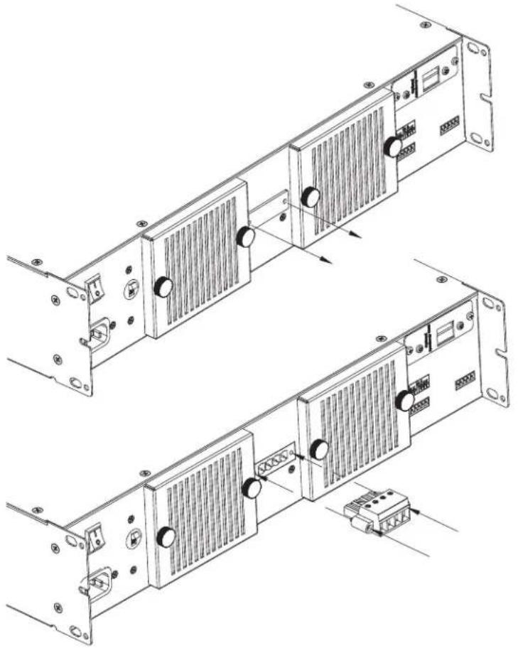
The HPA amplifiers ship with a protective plate covering the loudspeaker terminal pins. This is required by safety approval agencies due to the high voltage levels produced. Remove this cover and install the Euro Block type connector to connect loudspeakers to the amplifier. Any connections to the Euro Block type connector are to be made by a qualified electrical technician. Note: Make sure the amplifier is unplugged from the AC mains power source before starting the process because of the potential high voltage electrical risks involved. Discard the cover after it is removed and the loudspeaker terminal is installed. The removable Euro block connector is a 4 position, 7.62mm pitch and is connected to the chassis by 2 incorporated screws. It is recommended to use 12-gauge wire or lower for connection to the loudspeaker. The terminals can accept wire sizes of 6 - 18 gauge Class 2. Properly preparing the wire is critical to ensure a secure connection for safety and audio quality. First strip the wire back 0.250^t (5mm). We do not recommend tinning (soldering the wire). Insert the wire into the terminal block slot and secure by tightening the screws firmly. Failure to do so, could cause shock or damage the amplifier.
natural_image
Technical line drawing of a server rack with heat sinks and connectors (no text or symbols)10. Accessory Card Slot
The accessory card slot is for optional input cards such as the HPA-DAC2 (2 Channel Digital Audio Input Card). Contact AtlasIED for a full list of accessory cards. Note: Accessory card installation must be done by a qualified technician.
11. Air Inlet and Filters
The rear air inlet has a removable filter grill that is connected to the mains chassis via magnets. Filters are to remain clean at all times to assure proper air flow for amplifier cooling.

1601 Jack McKay Blvd. • Ennis, Texas 75119 U.S.A.
Telephone: 800.876.3333 • Fax: 800.765.3435
Placement of the Amp
Turn off all equipment before making connections. Install the amplifier in a standard-width 19" rack. It can be mounted above or below anything that does not generate excessive heat. Although the unit's chassis is shielded against radio frequency and electromagnetic interference, extremely high fields of RF and EMI should be avoided.
Ventilation - The appliance should be situated so that its location or position does not interfere with proper ventilation. For example, the HPA amplifier should not be situated in a sealed cabinet or on a shelf with obstacles on it that may impede the flow of air through the ventilation openings. It is recommended that it be rack mounted into an equipment rack.
Heat - The HPA amplifier should be situated away from heat sources such as radiators, heat registers, stoves, or other appliances (including amplifiers) that produce excessive heat. Ambient temperatures should not exceed 95^ (35°C) when equipment is in use.
Cabling
The HPA amplifier can be used with either balanced or unbalanced sources, and the outputs can be used with either balanced or unbalanced loads, provided the proper cabling is used. A balanced line is defined as two-conductor shielded cable with the two center conductors carrying the same signal but of opposite polarity when referenced to ground.
An unbalanced line is generally a single-conductor shielded cable with the center conductor carrying the signal and the shield at ground potential.
Balanced Input - AtlasLED recommends using either 20 or 22-gauge two-conductor wire with shield for low level signals. Maintain the proper polarity, + to +, - to - and shield to ground. Note: The ground center pin of the Phoenix connector is common for both channels.
Loudspeaker Outputs - Use 2 conductor unshielded wire of the appropriate gauge. Contact AtlasLED technical support at 1-800-876-3333 with questions regarding wire gauge. The number of loudspeakers connected and their tap settings will be required for technical support to properly recommend wire.
Why choose 230V over 120V?
It is a good idea to provide an AC Mains voltage of 208-240v with a product that requires high amount of AC Mains current. This configuration has advantages over a supply voltage of 120V. Ohm's law states that when voltage is high the current is lower. An amplifier that requires 30A of current at 120V only requires 15A of current at 230V.
One major advantage is the cost savings in the wire required to provide the current from the electrical panel to the receptacle. The minimum wire gauge needed to deliver 30A is 10AWG. For longer distances of 50ft - 150ft, 8AWG should be used. For 230V, only 15A is required and the wire gauge needed for that is only 14AWG. The cost between 14AWG & 8AWG is significant. Both methods only need 3 conductor. 208V - 240V in the USA requires a dual breaker. The cost of a dual breaker is similar in cost to a 120V 30A breaker.
The second advantage is with less current draw or demand there is less voltage sag in the AC Mains line. With less AC Mains voltage sag the amplifier will be able to produce more dynamic audio power when required.
Either 120V or 230V will work equally well, but keep in mind for a 120V service, using the proper wire gauge is very important to get the maximum performance out of the amplifier.
Connecting the HPA Amplifier to AC Mains
Do Not Do!
- Never plug an amplifier into a circuit without knowing what other products are connected to the same circuit.
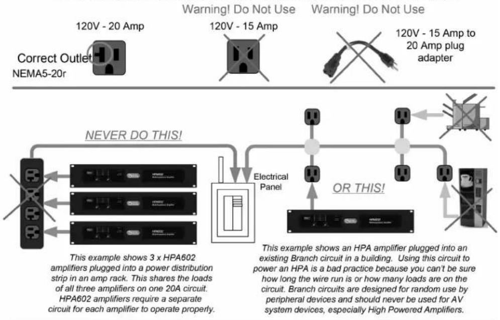
- Never plug an HPA602 or HPA1302 into a power strip. Always connect directly to a dedicated circuit wall receptacle. Power strips are not designed to deliver high amounts of continuous or peak current.
- Never plug a high power amplifier into an extension cord.
Best Practices
- Each high power amplifier should have its own dedicated AC Mains line.
- Consider using a 208V-240V AC mains power source.
HPA (HIGH POWER AMPS) REQUIRE SPECIAL ATTENTION TO AC POWER
Know the type of outlet you are going to use and never use an adapter!
flowchart
graph TD
    A["120V - 20 Amp"] --> B["Correct Outlet NEMA5-20r"]
    C["120V - 15 Amp"] --> D["Warning! Do Not Use"]
    E["120V - 15 Amp to 20 Amp plug adapter"] --> F["Warning! Do Not Use"]
    G["Electrical Panel"] --> H["OR THIS!"]
    I["This example shows 3 x HPA602 amplifiers plugged into a power distribution strip in an amp rack. This shares the loads of all three amplifiers on one 20A circuit. HPA602 amplifiers require a separate circuit for each amplifier to operate properly."] --> J["NEVER DO THIS!"]
    K["This example shows an HPA amplifier plugged into an existing Branch circuit in a building. Using this circuit to power an HPA is a bad practice because you can't be sure how long the wire run is or how many loads are on the circuit. Branch circuits are designed for random use by peripheral devices and should never be used for AV system devices, especially High Powered Amplifiers."] --> L["OR THIS!"]
BEST PRACTICE

text_image
Length of wire here adds to Load Dedicated 20 Amp Breaker for HPA Dedicated 20 Amp Breaker for Rack HE Power Strip 120V 20 Amp 120v 20 Amp Power Strip Use a separate AC Mains circuit for lower power consumption devices such as mixers. DSP processors and music sources. Dedicated AV Electrical Panel if possible This example shows a dedicated 120V 20 Amp service for the amplifier. #12 wire is required for a 20Amp circuit but may need up-sized based on the length of the Panel-to-Amp wire run. For rest of the equipment in the Head End Rack, use a second ded 20 amp circuit to the power Strip.
Atlas
IED.
1601 Jack McKay Blvd. • Ennis, Texas 75119 U.S.A.
Telephone: 800.876.3333 • Fax: 800.765.3435
HPA Amplifier Dante™ Accessory Card Installation
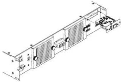
The HPA amplifier series allows for an optional HPA-DAC2 2-Channel Dante™ receiver card to be installed into the HPA amplifier. Contact AtlasLED for a list of accessory cards. Note: Accessory card installation must be done by a qualified technician.
- Remove the HPA amplifier from the AC mains source.
- Remove the two screws (M3 x 8mm Pan Head Black) holding the HPA accessory blank panel. Be careful and do not lose the screws.
- Remove the ribbon cable from the cover plate PCB connector.
- Connect the accessory card to the ribbon cable by carefully aligning the ribbon cable connector to the mating PCB connector. If aligned correctly the cable will mate easily.
- Carefully guide the accessory card into the slot without forcing the PCB or cable.
- After the card is inserted and the accessory panel is flush to the chassis, align the two screw holes and secure them together by using the M3 x 8mm screws.
natural_image
Technical line drawing of a server rack with ventilation grilles and ports (no text or symbols)HPA SERIES AMPLIFIERS USING OPTIONAL 2 CHANNEL DANTE™ CARD
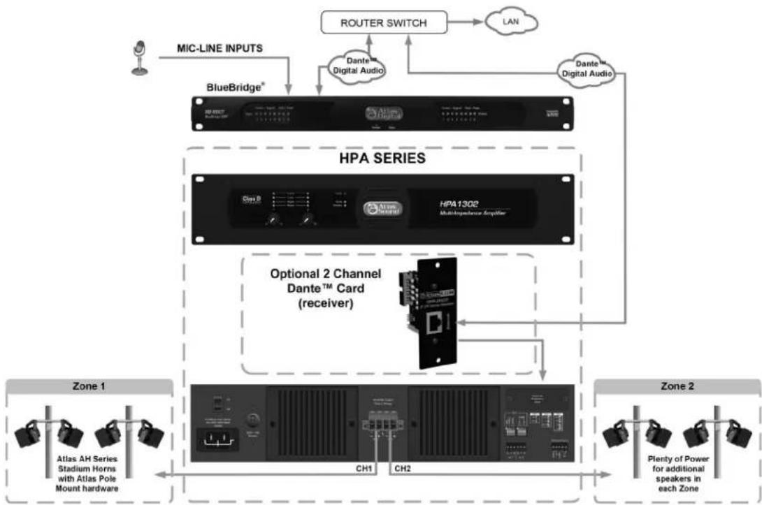
flowchart
graph TD
    A["User"] --> B["BlueBridge®"]
    B --> C["HPA SERIES"]
    C --> D["Optional 2 Channel Dante™ Card (receiver)"]
    D --> E["Zone 1"]
    D --> F["Zone 2"]
    C --> G["Router Switch"]
    G --> H["LAN"]
    C --> I["Dante™ Digital Audio"]
    C --> J["Dante™ Digital Audio"]
    C --> K["Ch1"]
    C --> L["Ch2"]
    style A fill:#f9f,stroke:#333
    style B fill:#ccf,stroke:#333
    style C fill:#cfc,stroke:#333
    style D fill:#fcc,stroke:#333
    style E fill:#ffc,stroke:#333
    style F fill:#ffc,stroke:#333
    style G fill:#fff,stroke:#333
    style H fill:#fff,stroke:#333
    style I fill:#fff,stroke:#333
    style J fill:#fff,stroke:#333
    style K fill:#fff,stroke:#333
    style L fill:#fff,stroke:#333

Atlas
IED
1601 Jack McKay Blvd. • Ennis, Texas 75119 U.S.A.
Telephone: 800.876.3333 • Fax: 800.765.3435
System
| Type Power Amplifier, 2 Channel | |
| Power Supply Type Switch Mode - Wide Range- PFC | |
| Amp Topology Class D | |
| Number of Fixed Inputs 2 | |
| Accessory Inputs 2 | |
| DSP Internal No | |
| Network No | |
| Optional Card Slot Yes | |
Output Power (Note 1) HPA602
HPA1302
| 100V x 2 CH | 2 x 300W | 2 x 650W |
| 70.7V X 2 CH | 2 x 300W | 2 x 650W |
| 8Ω x 2 CH | 2 x 300W | 2 x 650W |
| 4Ω x 2 CH | 2 x 300W | 2 x 650W |
| 2Ω x 2 CH | NA | NA |
| 8Ω Bridged | NA | NA |
| 4Ω Bridged | NA | NA |
Factory Default Settings (As Shipped)
| Amplifier Configuration | 2 CH |
| Level Controls | Front Panel |
| Control Ports (Rear Panel) | Remote Turn On / Off, Enable On |
| Input Sensitivity | .775 / 0dBu |
Inputs
| Input Quantity | 2-Balanced Inputs, Expandable to 4 via Accessory Card |
| Input Type | Balanced Line |
| Input Connectors Type | 3.5mm Euro Block |
| Input Impedance | 20KΩ (Balanced) 10KΩ (Unbalanced) |
| Input Sensitivity | 775mV / 1.0V / 32dB (Selectable) |
| Maximum Input Level dBu &Vrms | 24dBu, 12V (Accessory Slot Refer to Accessory Card Specifications) |
| Accessory Slot | 2 Input DanteTM Digital Card (HPA-DAC2 Optional) |
Level Control
| Front Panel | Rotary Stepped Attenuators with Security Cover |
| Status Indicators | |
| Power | Blue |
| Standby | Amber |
| AC Mains Out of Safe Operating Range | Red |
| Temp | Yellow |
| Ready | Green |
| Signal | Green |
| Output Limit | Yellow |
| Output Protect | Red |
| Bridge | NA |

Atlas
IED.川
1601 Jack McKay Blvd. • Ennis, Texas 75119 U.S.A.
Telephone: 800.876.3333 • Fax: 800.765.3435
GPIO Ports (Rear Panel)
| Number of Ports Qty 5 | |
| Type of Connector Euro Block 3.5mm | |
| Functions Remote Turn ON via Contact Closure | |
| Functions Remote Turn ON via DC Voltage 5-24V | |
| Functions Fault Report |
Configuration Settings (Rear Panel)
| Input Sensitivity .775V, 1V, 32dB per CH | |
| Parallel Inputs Yes | |
| Bridge NA |
Output Terminals (Speaker)
| Output Connectors Type Removable Euro Block, 7 | 62mm Pitch, Locking |
| Output Connectors Number of Terminals | 4 Position |
| Wire Size | 6-18 Gauge (Class 2 Wire) |
| Current Rating | 57A per Terminal |
Electrical Specifications (General)
| Total Harmonic Distortion 1 kHz and 1 dB Below Rated Power | ≤0.15% | |
| Signal to Noise Ratio | >70dB Below Rated Output (A-Weighted) | |
| Frequency Response | 20Hz - 20kHz (+0/-1.5dB) | |
| Input Impedance Balanced (Nominal) | 100Ω Balanced Line to Line | |
| Input Sensitivity | 0.775V / 1.0V / 32dB (Selectable) | |
| Slew Rate | >10V/μs | |
| Damping Factor (20Hz to 400Hz) | >200 | |
| Gain | 40dB (8Ω Factory Ship or 32dB Assignable) | |
| Crosstalk CH1-2 & CH 2-1 | >70dB | |
| Max Voltage Per Output 8Ω | 49V | 71V |
| Max Current per Output 4Ω | 8.9A | 12.9A |
| Protection | Soft Start, Input RF, DC, Short Circuit, Current Overload, Clip Limit, AC Mains Under / Over Voltage Shut Off, Peak Current Limit, Over Temp | |
AC Power Requirements
| Operating Voltage Auto Switch, 50/60Hz | 100V - 240V | |
| Minimum Power-Up Voltage | 95V | |
| Maximum Operating Voltage | 264V | |
| Mains Connector | C15 IEC Receptacle / Locking | C15 IEC Receptacle / Locking |
| Power Cord (Ships With) | IEC 16-Gauge 1.5M Cord w/ NEMA 5-15 Male Plug | IEC 16-Gauge 1.5M Cord w/ NEMA 5-15 Male Plug |
Power Consumption & Current Draw @ 120V AC Mains (HPA602)
| Standby Mode | 0.193A | 0.7W | 2.39 BTU |
| Idle Active | 0.592A | 43.5W | 148.4 BTU |
| Average Power 4Ω, All CH Driven | 1A | 124W | 269 BTU |
| Average Power 70.7V, All CH Driven | 1.1A | 134W | 303 BTU |
| Max Power 4Ω, All CH Driven | 7.3A | 849W | 856.4 BTU |
| Max Power 70V, All CH Driven | 6.9A | 802W | 607 BTU |
| Power Consumption & Current Draw @120V AC Mains (HPA1302) | Amps | Watts | BTU / hr (Note 4) |
| Standby Mode 0.194A 0.7W 2.39 BTU | |||
| Idle Active 0.568A 50W 170.6 BTU | |||
| Average Power 4 Ohm, All CH Driven 1.5A | 185W | 342.9 BTU | |
| Average Power 70.7V, All CH Driven | 1.5A | 182W 329 BTU | |
| Max Power 4 Ohm, All CH Driven | 15A | 1839W | 2009 BTU |
| Max Power 70V, All CH Driven | 14.4A | 1750W | 1706 BTU |
| Cooling | |||
| Cooling System | Fan (Variable With Temperature) | ||
| Air Inlet Filter | Yes, Rear, Washable | ||
| Cooling Air Flow Direction | Rear to Front | ||
| Dimensions and Weight | HPA602 | HPA1302 | |
| Rack Mount Requirements | 2 RU, 19" | ||
| Dimensions - Unit | 19' W x 3.5' H x 9.3' D (483mm x 89mm x 236mm) | ||
| Dimensions - Shipping | 22' W x 6.69" H x 16.5" D (560mm x 170mm x 420mm) | ||
| Weight - Unit | 14.8 lbs. (6.7kg) | 15.4 lbs. (7kg) | |
| Weight - Shipping | 17.9 lbs. (8.1kg) | 18.5 lbs. (8.4kg) | |
| Agency Approvals | |||
| North America Agency | ETL | ||
| Testing Standard North America | 60065 | ||
| FCC Class A (Conducted & Radiated Emissions) | Part 15 of the FCC Rules | ||
| CE | Yes (Includes RoHS & WEEE) | ||
| Optional Accessories | |||
| HPA-DAC2 - DanteTM Digital Audio Interface | 2 Channel Receive (Only)- Field Installable | ||
Notes:
- Power Level - Test is defined as follows: 1kHz sine wave signal burst of 20 cycles (20mS) at 1% THD+N, followed by 480 cycles of a 1kHz sine wave at 10% of the max power. Other power measurements available upon request.
- Power measured with Ethernet connected. Without Ethernet connected deduct 0.2W.
- Average Power is defined as Pink Noise input signal applied to achieve 1/4 of the 4Ω or 70.7V power rating.
- Max Power is defined as 1KHz input signal applied to achieve the maximum power output before clip into a 4Ω or 70.7V load.

Atlas

1601 Jack McKay Blvd. • Ennis, Texas 75119 U.S.A.
Telephone: 800.876.3333 • Fax: 800.765.3435
Notes:
Notes:

Atlas

1601 Jack McKay Blvd. • Ennis, Texas 75119 U.S.A.
Telephone: 800.876.3333 • Fax: 800.765.3435
Limited Warranty
All products manufactured by AtlasLED are warranted to the original dealer/installer, industrial or commercial purchaser to be free from defects in material and workmanship and to be in compliance with our published specifications, if any. This warranty shall extend from the date of purchase for a period of three years on all AtlasLED products, including SOUNDOLIER brand, and ATLAS SOUND brand products except as follows: one year on electronics and control systems; one year on replacement parts; and one year on Musician Series stands and related accessories. Additionally, fuses and lamps carry no warranty. AtlasLED will solely at its discretion, replace at no charge or repair free of charge defective parts or products when the product has been applied and used in accordance with our published operation and installation instructions. We will not be responsible for defects caused by improper storage, misuse (including failure to provide reasonable and necessary maintenance), accident, abnormal atmospheres, water immersion, lightning discharge, or malfunctions when products have been modified or operated in excess of rated power, altered, serviced or installed in other than a workman like manner. The original sales invoice should be retained as evidence of purchase under the terms of this warranty. All warranty returns must comply with our returns policy set forth below. When products returned to AtlasLED do not qualify for repair or replacement under our warranty, repairs may be performed at prevailing costs for material and labor unless there is included with the returned product(s) a written request for an estimate of repair costs before any nonwarranty work is performed. In the event of replacement or upon completion of repairs, return shipment will be made with the transportation charges collect.
EXCEPT TO THE EXTENT THAT APPLICABLE LAW PREVENTS THE LIMITATION OF CONSEQUENTIAL DAMAGES FOR PERSONAL INJURY, ATLASIED SHALL NOT BE LIABLE IN TORT OR CONTRACT FOR ANY DIRECT, CONSEQUENTIAL OR INCIDENTAL LOSS OR DAMAGE ARISING OUT OF THE INSTALLATION, USE OR INABILITY TO USE THE PRODUCTS. THE ABOVE WARRANTY IS IN LIEU OF ALL OTHER WARRANTIES INCLUDING BUT NOT LIMITED TO WARRANTIES OF MERCHANTABILITY AND FITNESS FOR A PARTICULAR PURPOSE.
AtlasIED does not assume, or does it authorize any other person to assume or extend on its behalf, any other warranty, obligation, or liability. This warranty gives you specific legal rights and you may have other rights which vary from state to state.
Service
Should your HPA Series Multi-Impedance Amplifier require service, please contact the AtlasIED warranty department at 1-877-689-8055, ext. 277 or support.atlasied.com to obtain an RA number.
AtlasIED Tech Support can be reached at 1-800-876-3333 or support.atlasied.com.
Visit our website at www.AtlasLED.com to see other Atlas products.
©2017 Atlas Sound L.P. The Atlas "Circle A", Soundolier, and Atlas Sound are trademarks of Atlas Sound L.P. IED is a registered trademark of Innovative Electronic Designs LLC. All Rights Reserved. All other trademarks are the property of their respective owners. All specs are subject to change without notice. ATS005600 RevA 3/17