CLA402 - Receiver Atlas Sound - Free user manual and instructions
Find the device manual for free CLA402 Atlas Sound in PDF.


| Product Type | 2-Channel Power Amplifier |
| Model | CLA402 |
| Total Output Power | 400W (configurable via Power Share) |
| Amplifier Topology | Class D |
| Power Supply | Switch-mode, auto-sensing 100V-240V AC, 50/60Hz |
| Number of Input Channels | 2 balanced line inputs |
| Input Connector Type | 3.5mm Euroblock (3-pin) |
| Number of Output Channels | 2 speaker outputs |
| Output Connector Type | Locking Euroblock, 5.08mm pitch, 2-position |
| Supported Load Configurations | 2Ω, 4Ω, 8Ω, 25V, 70V, 100V per channel |
| Power Share | Yes, rotary switch per two channels (200W/200W, 350W/50W, etc.) |
| Input Sensitivity | 1V (fixed) for full output |
| Frequency Response | 20Hz - 20kHz (+0/-1.5dB) for 4Ω/8Ω; 50Hz - 20kHz for 70V/100V |
| THD+N | < 0.15% at 1kHz, 1dB below rated power |
| Signal-to-Noise Ratio | > 93dBA (A-weighted) |
| Dimensions (W x H x D) | 8.5" x 1.75" x 13.77" (216mm x 44mm x 350mm) |
| Weight | 7 lbs (3.2 kg) |
| Rack Mounting | 1U, 19" rack-mountable (kit included for single or dual) |
| Cooling System | Convection in idle, variable-speed fan assist under signal |
| Standby Power Consumption | < 1W (Energy Star compliant) |
| Protection Features | Soft start, DC, short circuit, over current, over temperature, under/over voltage |
| Safety Compliance | TUV, FCC Class A, CE, RoHS |
| Maintenance & Cleaning | Clean with dry cloth only; do not use water or solvents; ensure ventilation openings are unobstructed |
| Warranty | 3 years (electronics and control systems: 1 year) |
Frequently Asked Questions - CLA402 Atlas Sound
User questions about CLA402 Atlas Sound
0 question about this device. Answer the ones you know or ask your own.
Ask a new question about this device
Download the instructions for your Receiver in PDF format for free! Find your manual CLA402 - Atlas Sound and take your electronic device back in hand. On this page are published all the documents necessary for the use of your device. CLA402 by Atlas Sound.
USER MANUAL CLA402 Atlas Sound
natural_image
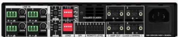
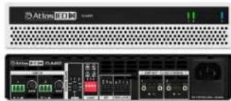
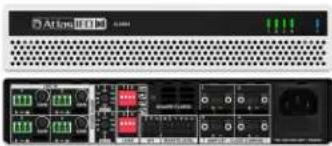
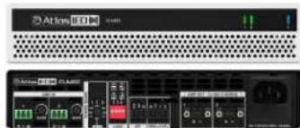
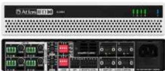
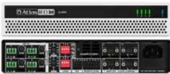
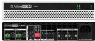
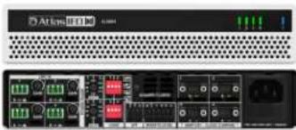
Exterior view of two Atlas IED CLA202 and CLA404 networking devices (no visible text or symbols on the device surfaces)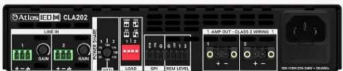
CLA SERIES
COMMERCIAL LITE AMPLIFIERS
CLA804 / CLA404 / CLA802 / CLA402 / CLA202
OWNER'S MANUAL
TABLE OF CONTENTS
| Introduction | 3 |
| Key Features | 3 |
| Important Safety Instructions | 4 |
| Front Panel Description | 6 |
| Rear Panel Description | 7 |
| Cabling & Placement of the Amplifier | 13 |
| CLA Amplifier Operation | 14 |
| Connecting the CLA Amplifier to AC Mains | 15 |
| Back Kit Installation | 17 |
| Specifications | 18 |
| 230V AC Mains Power Specifications | 29 |
| Dimensional Drawings | 33 |
| Warranty & Service | 34 |
CLA SERIES
COMMERCIAL LITE AMPLIFIERS
CLA804 / CLA404 / CLA802 / CLA402 / CLA202
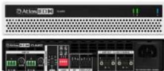
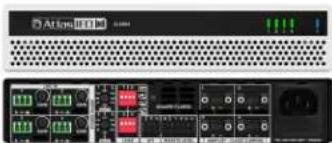
OWNER'S MANUAL
INTRODUCTION:
Thank you for your purchase of the AtlasIED CLA Series amplifier. The CLA Series is a high-power amplifier designed for versatility, suitable for both commercial 25V/70V/100V distributed systems and professional applications requiring amplification for low impedance loads like 4Ω or 8Ω. Notably compact and lightweight compared to similar-performing models, the CLA Series incorporates Class D Output topology, offering the efficiency of a Class AB amplifier without compromising on sound quality.
The amplifier's power supply adopts a switch-mode, global auto-sensing design, ensuring a stable output even in fluctuating power conditions. The power supply and output stage are meticulously engineered to deliver exceptional dynamic high output voltage and current to virtually any loudspeaker load.
Key features of the CLA Series include rear panel detented level controls, remote level control, GPI control for standby low energy mode, priority mute, and balanced inputs. The amplifiers also boast a unique output stage with a low-resistance, direct-coupled thermal transfer design, effectively maintaining optimal temperature across all loads and output levels. Additionally, the CLA Series amplifiers are energy-efficient, meeting Energy Star standards and drawing only 1W of power in standby mode.
Whether your application involves a large distributed constant voltage sound system or a high SPL sound reinforcement system, the AtlasIED CLA Series stands as the solution for high-power and cost-effective amplification needs.
AtlasIED AMPLIFIER POWER SHARE DESCRIPTION:
The AtlasIED Power Share feature is applicable to amplifiers with two channels of amplification, including 2 CH and 4 CH amplifiers, albeit controlled in pairs. Power Share enables the user to allocate a specified amount of audio amplified power to each channel. This allows for a deliberate imbalance where one amplifier channel can have more power than the other. Importantly, Power Share does not require any external devices like phones, tablets, or computers for configuration, nor does it rely on APP control software. The control for channel power is facilitated by a switch conveniently located on the amplifier.
In contrast to traditional amplifier designs where the power supply's maximum delivery is determined by the amplifier model's power rating, amplifiers with multiple channels that share a common power supply typically have fixed channel amplifier ratings. For example, a two-channel amp producing 200W per channel necessitates a 400W power supply. However, with AtlasIED Power Share technology, a 400W power supply can be configured using a switch. When selected, this switch configures the amplifier to allocate 350W of power to Channel 1 and 50W to Channel 2. The combined power of both channels still totals the maximum 400W from the power supply. Furthermore, individual channels can still be configured to deliver 200W each if desired.
KEY FEATURES:
• CLA404 / CLA804 Four Amplifier Channels
• CLA202 / CLA402 / CLA802 Two Amplifier Channels
- Individual Channel Load Configurations of 20, 40, 80, 25V, 70.7V, & 100V
• Power Share Per Two Channels (Patent Pending)
• Balanced Inputs
• Priority Mute
• Remote Level Control Per Channel
• Energy Savings Standby
• Rear Panel Attenuators
• Auto Sensing 100V - 240V\~ AC Mains Power Supply
• Meets Energy Star Standards 1W Standby Mode
- Convection Cooling In Idle Mode, Fan Assist Under Signal
OWNER'S MANUAL
IMPORTANT SAFETY INSTRUCTIONS
- Read these instructions.
- Keep these instructions.
- Heed all warnings.
- Follow all instructions.
- Do not use this device near water.
- Clean only with dry cloth.
- Do not block any ventilation openings. Install in accordance with the manufacturer's instructions.
- Do not install near any heat sources such as radiators, heat registers, stoves, or other device that produce heat.
- Do not defeat the safety purpose of the polarized or grounding-type plug. A polarized plug has two blades with one wider than the other. A grounding type plug has two blades and a third grounding prong. The wide blade or the third prong are provided for your safety. If the provided plug does not fit into your outlet, consult an electrician for replacement of the obsolete outlet.
-
Protect the power cord from being walked on or pinched particularly at plugs, convenience receptacles, and the point where they exit from the device.
-
Only use attachments / accessories specified by the manufacturer.
-
Use only with the cart, stand, tripod, bracket, or table specified by the manufacturer, or sold with the device. When a cart is used, use caution when moving the cart / device combination to avoid injury from tip-over.

-
Unplug this device during lightning storms or when unused for long periods of time.
-
Refer all servicing to qualified service personnel. Servicing is required when the device has been damaged in any way, such as power-supply cord or plug is damaged, liquid has been spilled, or objects have fallen into the device, the device has been exposed to rain or moisture, does not operate normally, or has been dropped.
-
This product is equipped with a three-wire grounding-type plug, a plug having a third (grounding) pin. This plug will only fit into a grounding-type power outlet. This is a safety feature. If you are unable to insert the plug into the outlet, contact your electrician to replace your obsolete outlet. Do not defeat the safety purpose of the grounding-type plug.
-
WARNING: To reduce the risk of fire or electric shock, this device should not be exposed to dripping, splashing, rain, or moisture, and objects filled with liquids, such as a vase, should not be placed on this device.
-
To completely disconnect this equipment from the mains, disconnect the power supply cord plug from the receptacle.
-
The mains plug of the power supply cord shall remain readily operable.
-
Protective earthing terminal. The apparatus should be connected to a mains socket with a protective earthing connection.

CAUTION - SHOCK RISK
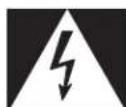
The lightning flash with arrowhead symbol within an equilateral triangle, is intended to alert the user to the presence of uninsulated "dangerous voltage" within the product's enclosure that may be of sufficient magnitude to constitute a risk of electric shock to persons.

The exclamation point within an equilateral triangle is intended to alert the user to the presence of important operating and maintenance (servicing) instructions in the literature accompanying the product.


WARNING: SHOCK HAZARD - DO NOT OPEN AVIS: RISQUE DE CHOC ELÉCTRIQUE - NE PAS OUVRIR
WARNING: TO REDUCE THE RISK OF FIRE OR ELECTRIC SHOCK DO NOT EXPOSE THIS EQUIPMENT TO RAIN OR MOISTURE
AVIS: NE PAS EXPOSER CE MATÉRIEL À LA PLUIE OU L'HUMIDITE AFIN DE REDUIRE LE RISQUE D'INFLAMMATION OU DE CHOC ELÉCTRIQUE
CLA SERIES
COMMERCIAL LITE AMPLIFIERS
CLA804 / CLA404 / CLA802 / CLA402 / CLA202
OWNER'S MANUAL
IMPORTANT SAFETY INSTRUCTIONS
WARNING - WHEN THE DEVICE IS IN USE:
- WARNING: For the terminals marked with symbol of 4 may be of sufficient magnitude to constitute a risk of electric shock. The external wiring connected to the terminals requires installation by an instructed person or the used of ready-made leads or cords.
- WARNING: The apparatus shall not be exposed to dripping or splashing and that objects filled with liquids, such as vases, shall not be placed on apparatus.
- WARNING: The mains plug is used as disconnect device, the disconnect device shall remain readily operable.
• To prevent electric shock, do not remove the product cover as there are high voltage components inside. Refer all servicing to AtlasLED. - Should any of the following irregularities occur during use, immediately switch off the power, disconnect the power cord from the AC outlet and contact AtlasIED. Do not to attempt to continue operation with the product as this may cause fire or electric shock:
• Smoke or strange smell coming from the unit.
• If the product falls or the case is damaged.
- If water or any metallic objects falls into the product.
- If the power supply cord is damaged in any way.
- If the unit is malfunctioning.
- Do not insert or drop metallic objects or flammable materials into the ventilation holes of the product's cover, as this may result in electric shock or fire.
- Do not place any containers with liquid or metallic objects on the top of the product. If any liquid spills into the unit, fire or electric shock may result.
- Never operate this product or touch the power supply cord during an electrical storm, electric shock may result.
- Never exceed the power rating on the product when connecting equipment. Fire and/or property damage may result
- Operate the product only with the voltage specified on the unit. Fire and/or electric shock may result if a higher voltage is used.
- Do not modify, kink, or cut the power cord. Do not place the power cord in close proximity to heaters and do not place heavy objects on the power cord, including the product itself, doing so may result in fire or electrical shock.
- Ensure that the safety ground terminal is connected to a proper ground. Never connect the ground to a gas pipe as a catastrophic disaster may result.
- Be sure the installation of the product is stable, avoid slanted surfaces as the product may fall and cause injury or property damage.

CAUTION - WHEN INSTALLING THE PRODUCT:
- Plugging in or unplugging the power cord with wet hands may result in electric shock.
- Never move the unit with the power cord plugged into the wall, as damage to the power cord may result.
- When unplugging the cord from the wall, grasp the plug, NOT the cord.
- Never install this product in humid or dusty locations, nor in direct sunlight, near sources of heat, or in areas where sooty smoke or steam are present. Fire and electric shock may result.
- Keep all sides of the unit at least 3 12 " away from objects that may obstruct air flow to prevent the unit's internal temperature rise.

CAUTION - WHEN THE PRODUCT IS IN USE:
- Never place heavy objects on the product, causing it to fall and/or break, resulting in personal injury and property damage. In addition, the product itself may fall and cause injury and property damage.
- Contact AtlasLED for instructions on cleaning the inside of the unit. Large accumulations of dust inside the unit may result in heat buildup and fire.
- Ensure that the power supply plug is securely plugged into the wall outlet. Never allow dust to accumulate on the power plug or inside the wall outlet.
- When cleaning the unit or the unit is not to be operated for an extended period, unplug the power cord from the wall.
OWNER'S MANUAL
FRONT PANEL
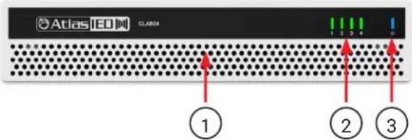
1. VENTILATION / COOLING
The CLA amplifiers are equipped with fan-assist cooling, which functions by drawing cool air in from the front of the amp and expelling hot air through the rear and side panels. The cooling system of the CLA Series includes an idle mode with convection cooling and variable-speed fan assist cooling during amplification. Notably, the design of the CLA Series is such that air filters are not necessary. However, in environments with high levels of dust or dirt, occasional cleaning may be required to ensure optimal performance.
2. CHANNEL STATUS INDICATORS
The CLA Channel Status indicator employs RGB LED technology to offer a visual indication of various conditions related to the channel's operation. Each channel has a separate indicator:
A. Clear (Off) - The LED will not illuminate, indicating that the amplifier channel is stable and ready for use.
B. Green (Blinking) - The LED will blink green when 25mV if input signal is applied to the amplifier.
C. Yellow (Blinking) - The LED will blink yellow when the maximum amplifier output level is achieved.
D. Red (Blinking) - The LED will blink red when the amp channel exceeds the maximum current settings, indicating a wrong load selection. Confirm that the load applied to the amp channel and the load switch selection match.
Note: If one of the speaker outputs has a short, the amplifier will go into protect mode with all Channel LED's and the AC main LED blinking Red. The amplifier will try to reset itself every 20 seconds until the short has been removed.
E. Red (Steady) - The LED will be steady red when the amp channel is in protect mode. Remove the speaker load from the amp channel, and if the LED turns off, look for a short in the speaker line. If the LED continues to illuminate and the speaker load is removed from the amp channel, contact AtlasLED Tech Support.
F. Yellow (Steady) - The LED will be steady yellow when the channel is in a thermal protect condition. Once the thermal condition is resolved, the yellow LED turns off.
3. AC MAINS & POWER SUPPLY STATUS INDICATOR
The CLA Power Supply Status indicator utilizes RGB LED technology to provide a visual indication of various conditions related to the incoming AC mains and the amplifier's power supply.
A. Idle Mode (Blue Blinking) - The LED will blink blue indicating the amplifier is in a low power state. The fans ore off during this state with the amplifier operating in convection cooling mode. The amplifier is ready to receive a signal and has no wake up delay
B. Power On Mode (Blue Steady) - The LED will illuminate a steady blue state when proper AC mains power is applied to the amplifier, indicating that the amplifier is active and ready for use.
C. Standby Mode (Yellow Steady) - A steady yellow state indicates Standby mode, where the amplifier's power supply is in Energy Save Mode, and the amplifier is not ready for use. To activate Standby mode, the rear panel remote activation control GPI must be triggered by shorting the (STB) and ground (G) pins together. In Standby mode, the CLA power consumption is less than 1 watt, and the amplifier will not pass audio.
D. Protect Mode (Red Steady) - The LED will be steady red in the event of a fault condition with the power supply. If this occurs, unplug the amplifier from the AC mains and have the AC mains inspected by a qualified technician. If the AC power is stable, plug the CLA amplifier back in. If the LED remains red, contact AtlasLED Tech Support.
E. AC Fault (Red Blinking) - The LED will blink red when there is low or high AC mains voltage, indicating a fault condition with the AC mains powering the amplifier. Under this condition, the amplifier will not function until the AC mains are within the amplifier's voltage requirements. CLA AC Mains operating voltage requirements are 100V - 132V and 208V - 240V.
Note: If one of the speaker outputs has a short, the amplifier will go into protect mode with all Channel LED's and the AC main LED blinking Red. The amplifier will try to reset itself every 20 seconds until the short has been removed.
F. Thermal Protection (Yellow Blinking) - This LED represents the temperature condition of the amplifier. It will blink yellow if the power supply's the rmal protection is triggered, causing the power output to reduce. This allows the amplifier to cool down while still remaining functional.
OWNER'S MANUAL
REAR PANEL
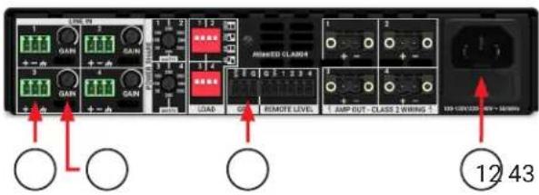
1. AC MAINS INPUT
The CLA Series is equipped with a global, wide-range AC Mains power supply that functions on 100V-120V and 220V-240V 50/60Hz power sources. The amplifiers feature an IEC-600320-C14 receptacle and come with a detachable 1.8-meter 14-gauge NEMA 5-15 power cord. Insert the IEC connector of the power cord into the IEC receptacle of the CLA Series amplifier, ensuring it is securely connected. For non-North American applications, refer to local electrical code requirements to select the appropriate power cord.
2. BALANCE INPUT
Connect balanced line level signals to the (+) (−) and (G) terminals. Note: If connecting an unbalanced line level input, short the (G) and (−) terminals together.
3. CHANNEL LEVEL CONTROLS
Each channel of the CLA amplifier features an independent detented level control. When either potentiometer is turned down (left or fully counterclockwise), no signal will come out of the corresponding amp channel. When turned up (right or fully clockwise), the amp will be set for maximum level.
4. GPI CONTROL PORT
The CLA GPI control port serves two functions:
A. Standby Mode - Connect Pin 1 (STB) to Pin 3 (G) via a switch to activate Standby mode, muting all channels and placing the amplifier in Energy
B. Save mode. When Standby is activated, the AC Mains Power LED illuminates a steady Yellow state, and power consumption is less than 1W.
C. Switch requirements are low voltage and current SPST.
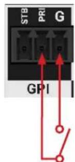
D. Priority Mode - Connect Pin 2 (PRI) to Pin 3 (G) via switch to activate Priority mode, muting all inputs. Switch requirements are low voltage and current SPST. All Channel LED's will blink Red.
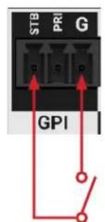
- Standby Mode • Priority Mode
REAR PANEL - (CONTINUED ON NEXT PAGE)
CLA SERIES
COMMERCIAL LITE AMPLIFIERS
CLA804 / CLA404 / CLA802 / CLA402 / CLA202
OWNER'S MANUAL
REAR PANEL - (CONTINUED)
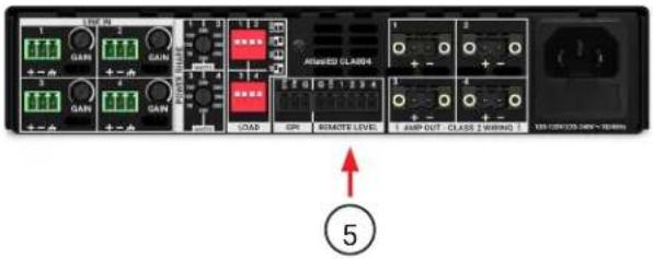
5. REMOTE LEVEL CONTROL PORT
To enable remote control of the level on the CLA Series, you can use the Remote Level Control port. This control port operates on a 10K0 based system, and it is recommended to use the optional AtlasIED WPD-VC10K wall control for this purpose. Follow these guidelines for proper setup:
A. Recommended Control - It is recommended to use the optional AtlasIED WPD-VC10K wall control.
B. System Configuration - Set the system's maximum levels using the amplifier level controls. Then, utilize the remote 10KΩ linear potentiometer as an attenuator.
C. Wiring Requirements - Wiring the WPD-VC10K will require three-conductor unshielded wire, connecting the WPD terminals to the amplifier.
D. Maximum Distance - The maximum distance for wiring can be up to 500 feet.
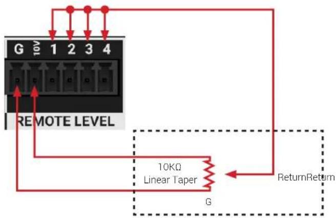
E. Individual or Combined Control - Note that each channel of the CLA amplifier can be controlled individually or combined. Connect the "G" pin to the Low Z side of the pot and the 10V to the Hi Z side of the pot.
F. Wiring Details - The wiper (P3 Below) of the pot should connect to the channel return pins labeled 1, 2, 3, or 4. When 10VDC is applied to the channel return pin, the amplifier will be at full power. Note: If the level control is not operating in the following manner with the level control is to the right (Fully Clockwise) the amplifier output is at maximum and with the level control is the left (Fully Counterclockwise) the +10V and the G are reversed.
Please ensure that the wiring is done using proper techniques and adhere to safety guidelines. If in doubt, consult the user manual or contact AtlasIED support for further assistance.
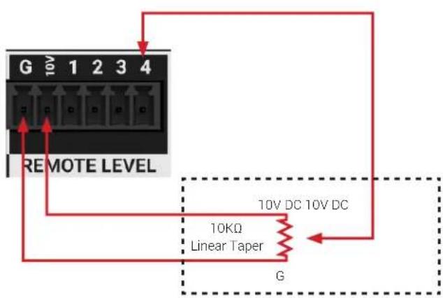
Single level control to one channel
flowchart
graph TD
    A["Remote Level"] --> B["10KΩ Linear Taper"]
    B --> C["Return Return"]
    D["G"] --> A
    E["G"] --> A
    F["G"] --> A
    G["G"] --> A
    H["G"] --> A
    I["G"] --> A
    J["G"] --> A
    K["G"] --> A
    L["G"] --> A
    M["G"] --> A
    N["G"] --> A
    O["G"] --> A
    P["G"] --> A
    Q["G"] --> A
    R["G"] --> A
    S["G"] --> A
    T["G"] --> A
    U["G"] --> A
    V["G"] --> A
    W["G"] --> A
    X["G"] --> A
    Y["G"] --> A
    Z["G"] --> A
Single level control to multiple channels
REAR PANEL - (CONTINUED ON NEXT PAGE)
8
CLA SERIES
COMMERCIAL LITE AMPLIFIERS
CLA804 / CLA404 / CLA802 / CLA402 / CLA202
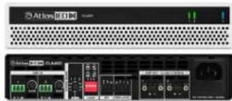
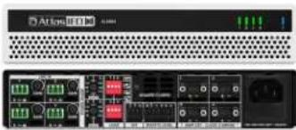
OWNER'S MANUAL
REAR PANEL - (CONTINUED)
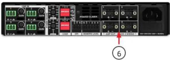
6. LOUDSPEAKER CONNECTION
The CLA Series amplifiers are equipped with a locking Euro Block type connector. Please follow these guidelines when working with the connector, keeping safety in mind:
A. Safety Precautions - Before starting the process, ensure that the amplifier is unplugged from the AC mains source to avoid potential high voltage electrical shock.
B. Connector Details - The removable Euroblock connector is a 2-position, 5.08mm pitch design and is connected to the chassis by the 2 incorporated screws.
C. Wire Gauge Recommendation - It is recommended to use 14-gauge wire or larger for connecting to the loudspeaker.
D. Wire Size Acceptance - The terminals can accept wire sizes of 18-gauge to 12-gauge Class 3 wiring.
E. Wire Preparation - Properly prepare the wire by stripping it back 0.250" (5mm). We do not recommend tinning (soldering the wire).
F. Connection Process - Insert the wire into the terminal block slot and secure it by tightening the screws firmly. This step is critical to ensuring secure connection for both safety and optimal audio quality.
G. Caution - Failure to tighten the screws securely could lead to electrical shock or damage to the amplifier.
Always follow safety guidelines and manufacturer recommendations when working with audio equipment. If you have any doubts or concerns, consult the user manual or contact the manufacturer's support for clarification and assistance.
REAR PANEL - (CONTINUED ON NEXT PAGE)
CLA SERIES
COMMERCIAL LITE AMPLIFIERS
CLA804 / CLA404 / CLA802 / CLA402 / CLA202
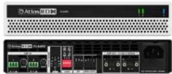
OWNER'S MANUAL
REAR PANEL - (CONTINUED)
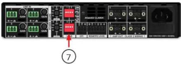
7. AMPLIFIER LOAD CONFIGURATION SWITCHES - IMPORTANT!
The CLA Amp series provides flexibility in configuring load requirements, allowing independent load selections for each channel. Each channel can be configured for 2Ω, 4Ω, 8Ω, 25V, 70V, and 100V loads. Two Dip Switches dedicated to each specific channel are used for configuring the amplifier channels' load selections.
A. Safety Precautions - Before starting the process, ensure that the amplifier is unplugged from the AC mains source to avoid potential high voltage electrical shock.
B. Connector Details - The removable Euroblock connector is a 2-position, 5.08mm pitch design and is connected to the chassis by the 2 incorporated screws.
C. Wire Gauge Recommendation - It is recommended to use 14-gauge wire or larger for connecting to the loudspeaker.
D. Wire Size Acceptance - The terminals can accept wire sizes of 18-gauge to 12-gauge Class 3 wiring.
E. Wire Preparation - Properly prepare the wire by stripping it back 0.250" (5mm). We do not recommend tinning (soldering the wire).
F. Connection Process - Insert the wire into the terminal block slot and secure it by tightening the screws firmly. This step is critical to ensuring secure connection for both safety and optimal audio quality.
G. Caution - Failure to tighten the screws securely could lead to electrical shock or damage to the amplifier. Always follow safety guidelines and manufacturer recommendations when working with audio equipment. If you have any doubts or concerns, consult the user manual or contact the manufacturer's support for clarification and assistance.
Important Note: Failure to choose the proper setting for the load applied may cause the amplifier to go into protect mode.
Dip Switch Configuration:
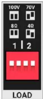
• DIP SWITCH #1 & #2: Channel 1 Load Selection
• DIP SWITCH #3 & #4: Channel 2 Load Selection
Channel 1 Load Selection Switch Positions:
• 100V: DP SW #1 UP & #2 UP
• 70V: DP SW #1 UP & #2 DOWN
• 8Ω: DP SW #1 DOWN & #2 DOWN
• 4Ω: DP SW #1 DOWN & #2 UP
Note: For 2Ω loads or 25V systems, use 4Ω switch settings. Refer to the power specifications for power ratings corresponding to the selected load. By following the provided chart and ensuring the correct Dip Switch positions, you can tailor the amplifier's load configuration to suit your specific needs. Always refer to the user manual for additional details and specifications.
REAR PANEL - (CONTINUED ON NEXT PAGE)
OWNER'S MANUAL
REAR PANEL - (CONTINUED)
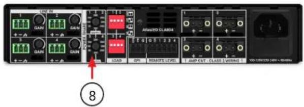
8. POWER SHARE SELECTION
The Power Share rotary switch in the CLA Amp series allows you to direct the amplifier's power between two channels. The number of Power Share rotary switches depends on the amplifier model: CLA402 / CLA202 2-channel amps have one Power Share switch, while CLA804 / CLA404 4-channel amps have two Power Share switches.
A. Power Supply and Channels - For every two amplifier channels, there is one dedicated power supply, each with a maximum power delivery in watts.
B. Power Share Operations - Power Share enables you to direct the power between channels by selecting the power level using the Power Share rotary switch.
C. Switch Indication - The Power Share switch has a double arrow indicator to show the power selection between the two channels.
D. Example - CLA402 - The CLA402, being a two-channel amp, has a single 400W power supply shared between CH 1 & CH 2. If the Power Share switch is set at 200W for CH 1 and 200W for CH 2, each channel receives an equal 200W. Rotating the switch one click to the right may result in CH 2 getting 350W and CH 1 receiving 50W, while the total power between both channels remains 400W. Importantly, the load selection does not affect the Power Share selection.
Always refer to the user manual for detailed instructions on using the Power Share feature specific to your amplifier model. The double arrow indicator and clear labeling on the switch assist in visualizing the power distribution between channels.
E. Power Share Selection Examples
- Fig 1 - CLA402 Power Share selections arrow pointer is set to 200W for CH 1 / CH 2
- Fig 2 - CLA804 Power Share selection arrow is set to 200W CH 1 / CH 2 and 200W for CH 3 / CH 4
- Fig 3 - CLA202 Power Share selections arrow pointer is set to 100W for CH 1 / CH 2
- Fig 4 - CLA404 Power Share selection arrow is set to 100W CH 1 / CH 2 and 100W for CH 3 / CH 4
- Fig 5 - CLA802 Power Share selection arrow pointer is 400W CH 1 / CH 2
Note: Power Share selections are not affected by the load selections.
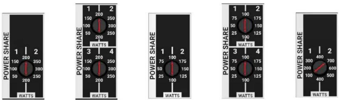
Fig. 1 Fig. 2 Fig. 3 Fig. 4 Fig. 5
REAR PANEL - (CONTINUED ON NEXT PAGE)
CLA SERIES
COMMERCIAL LITE AMPLIFIERS
CLA804 / CLA404 / CLA802 / CLA402 / CLA202
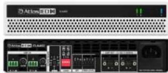
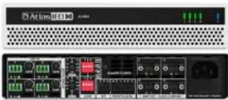
OWNER'S MANUAL
REAR PANEL - (CONTINUED)
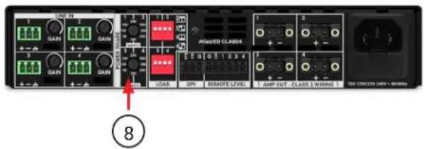
This example below shows the Power Share Selection can be different between channels
- Fig 6 - CLA402 Power Share selections arrow pointer is set to CH 1 50W (70V) / CH 2 350W (4Ω)
- Fig 7 - CLA804 Power Share selection arrow is set to CH 1 50W (100V) / CH 2 350W (8Ω) and CH 3 50W (100V) / CH 4 350W (8Ω)
- Fig 8 - CLA202 Power Share selections arrow pointer is set to CH 1 50W (70V) / CH 2 150W (4Ω)
- Fig 9 - CLA404 Power Share selection arrow is set to CH 1 25W (70V) / CH 2 175W (70V) and CH 3 75W (70V) / CH 4 125W (70V)
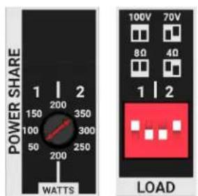
Fig. 6
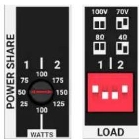
Fig. 7
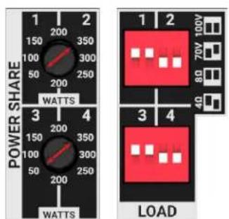
Fig. 8
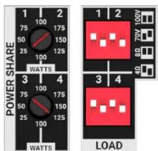
Fig. 9
CLA SERIES
COMMERCIAL LITE AMPLIFIERS
CLA804 / CLA404 / CLA802 / CLA402 / CLA202
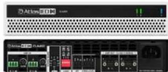
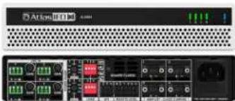
OWNER'S MANUAL
CABLING
The CLA amplifier can be used with either balanced or unbalanced sources, and the outputs can be used with either balanced or unbalanced loads, provided the proper cabling is used. A balanced line is defined as a two-conductor shielded cable with the two center conductors carrying the same signal but of opposite polarity when referenced to ground.
An unbalanced line is generally a single-conductor shielded cable with the center conductor carrying the signal and the shield at ground potential.
Balanced Input - AtlasIED recommends using either 20-gauge or 22-gauge two-conductor wire with shield for low level signals. Maintain the proper polarity, (+) to (+), (−) to (−), and shield to ground. Note: The ground center pin of the Phoenix connector is common for both channels.
Loudspeaker Outputs - Use Class 2, 2 conductor unshielded wire of the appropriate gauge. Contact AtlasIED technical support at 1-800-876-3333 with questions regarding wire gauge. The number of loudspeakers connected, and their tap settings will be required for technical support to properly recommend wire.
PLACEMENT OF THE AMP
Turn off all equipment before making connections. Install the amplifier in a standard-width 19' rack. It can be mounted above or below anything that does not generate excessive heat. Although the unit's chassis is shielded against radio frequency and electromagnetic interference, extremely high fields of RF and EMI should be avoided.
Ventilation - The appliance should be situated so that its location or position does not interfere with proper ventilation. For example, the CLA amplifier should not be situated in a sealed cabinet or on a shelf with obstacles on it that may impede the flow of air through the ventilation openings. It is recommended that it be rack mounted into an equipment rack.
Heat - The CLA amplifier should be situated away from heat sources such as radiators, heat registers, stoves, or other appliances (including amplifiers) that produce excessive heat. Ambient temperatures should not exceed 95°F (35°C) when equipment is in use.
CLA GAIN vs INPUT SENSITIVITY
Gain is the input voltage to obtain a specific output voltage, not the amount of current or watts. The power delivered by an amplifier is determined by the load and the voltage applied across it. Input sensitivity is the amount of input voltage required to an amplifier to reach full output.
LOW Z-GAIN
The gain settings for the 8-0 and 4-0 mode change with each Power Share power level setting. This design ensures that full power output is achieved when a 1V signal is applied, regardless of the Power Share selection. While this approach is not typical in amplifier designs, it is necessary due to the 16 variations available for each channel. Maintaining a consistent input sensitivity across different load types and power level selections is the only way to achieve uniform calibration between zones and amplifier channels.
HIGH Z-GAIN
The gain remains consistent for all 70V or 100V Power Share settings to achieve the same output voltage of 70V, while the load changes to accommodate different power levels.
LO Z & HIGH Z-GAIN
The gain is different between Low Z (Lo Z) and High Z (Hi Z) because it requires significantly more signal to achieve a 100V output compared to a 4-Ω output. If all the gains were the same, it would take approximately three times the input signal for a 100V output compared to that for a 4-Ω load. The CLA804 gain is 29dB 4-Ω, 32dB 8-Ω, 37dB 70V, 40dB 100V.
CLA SERIES
COMMERCIAL LITE AMPLIFIERS
CLA804 / CLA404 / CLA802 / CLA402 / CLA202
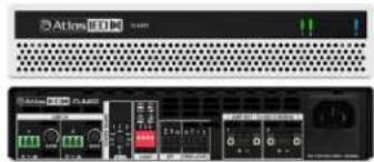
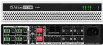
OWNER'S MANUAL
The CLA amplifier is indeed versatile, designed for both high-voltage and high-current demands, making it adaptable to both distributed 100V systems and low-impedance setups down to 20. In distributed systems, where an amplifier needs to output 70V or 100V to drive multiple speakers over long distances, It's a challenge for low-power amplifiers (under 200W) to step up the voltage. The CLA amplifiers tackles this by maintaining voltage at these high levels effectively.
For low-impedance systems (20, 40, or 80) the amp delivers high current. While the voltage demands are lower, the amplifier's Class D output stage ensures stable, efficient current delivery for 80 and 40 loads and can handle 20 loads as well. Power availability for 20 is contingent on the power supply available current. 20 loads requires twice the current of a 40 load. Hence, the specification is conservatively rated, yet in practical applications, the delivered power at 20 often surpasses these figures. For 20 setups, use the 40 settings. The CLA will auto sense 20 loads.
In a 25V distributed audio system, the current requirements are significantly higher compared to systems operating at 70V or 100V. 25 system can be considered a low impedance audio system, where the power and voltage required results in lower impedance loads being applied to the amplifier.
For example, if you have 20 25V speakers tapped at 10W each, the total power requirement from the amplifier would be 200W at 25V. To determine the load impedance applied to the amplifier, you can use Ohm's Law. The formula is: V Squared ÷ Power = Z (25v x 25v = 625, 625 divided by 200W = 3.1Ω. This is the load applied to the amplifier.
For optimal performance in 25V systems, the CLA loads switch should be set to 40. The CLA amplifiers are designed to auto-sense the load within an impedances range. However, if the power requirement exceeds 200W, the load impedance will drop below 20, which will limit the amplifier's power output. This is why models CLA402 & CLA404 reduce power from 400W to 200W for 25V applications.
CLA SERIES
COMMERCIAL LITE AMPLIFIERS
CLA804 / CLA404 / CLA802 / CLA402 / CLA202
OWNER'S MANUAL
CONNECTING THE CLA AMPLIFIER TO AC MAINS
DO NOT DO!
- Never plug a CLA Series amplifier into a circuit without knowing what other products are connected to the same circuit.
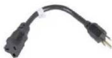
- Never plug a CLA Series amplifier into a power strip. Always connect directly to a dedicated circuit wall receptacle. Power strips are not designed to deliver high amounts of continuous or peak current.
- Never plug an CLA Series amplifier into an extension cord.
CLA (Commercial Lite Amps) require special attention to AC power
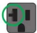
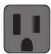
Know the type of outlet you are going to use and never use an adapter!
Correct Outlet
120V - 20 Amp (NEMA5-20r)
Correct Outlet
120V - 15 Amp
Warning! Do Not Use
120V - 15 Amp to 20 Amp plug adapter
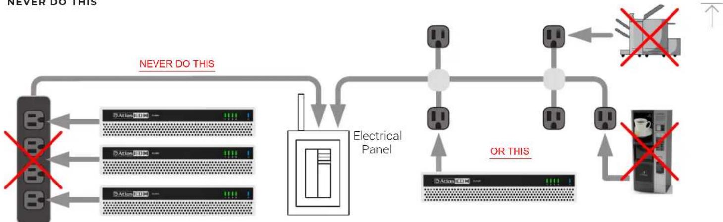
NEVER DO THIS
flowchart
graph TD
    A["AT&T Device"] -->|YES| B["Electrical Panel"]
    A -->|NO| C["Switch 1"]
    A -->|YES| D["Switch 2"]
    A -->|NO| E["Switch 3"]
    B --> F["OR This"]
    C --> F
    D --> F
    E --> F
    style A fill:#f9f,stroke:#333
    style B fill:#ccf,stroke:#333
    style C fill:#ccf,stroke:#333
    style D fill:#ccf,stroke:#333
    style E fill:#ccf,stroke:#333
    style F fill:#cfc,stroke:#333
This example shows 3 x CLA amplifiers plugged into a power distribution strip in an amp rack. This shares the loads of all three amplifiers on one 15A circuit. CLA amplifiers require a separate circuit for each amplifier to operate properly.
This example shows a CLA amplifier plugged into an existing branch circuit in a building. Using this circuit to power a CLA amplifier is a bad practice because you can't be sure how long the wire run is or how many loads are on the circuit. Branch circuits are designed for random use by peripheral devices and should never be used for AV system devices, especially CLA amplifiers.
CONNECTING THE CLA AMPLIFIER TO AC MAINS - (CONTINUED ON NEXT PAGE)
CLA SERIES
COMMERCIAL LITE AMPLIFIERS
CLA804 / CLA404 / CLA802 / CLA402 / CLA202
OWNER'S MANUAL
CONNECTING THE CLA AMPLIFIER TO AC MAINS - (CONTINUED)
BEST PRACTICES
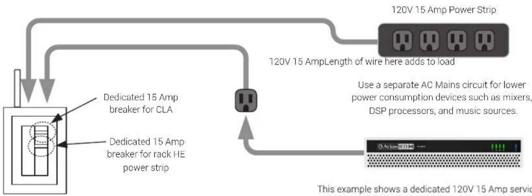
flowchart
graph TD
    A["120V 15 Amp Power Strip"] --> B["Dedicated 15 Amp Breaker for CLA"]
    B --> C["Dedicated 15 Amp Breaker for rack HE power strip"]
    C --> D["AC Main 120V 15 Amp Service"]
    D --> E["Use a separate AC Mains circuit for lower power consumption devices such as mixers, DSP processors, and music sources."]
    style A fill:#f9f,stroke:#333
    style B fill:#ccf,stroke:#333
    style C fill:#cfc,stroke:#333
    style D fill:#fcc,stroke:#333
    style E fill:#cff,stroke:#333
Dedicated AV electrical panel if possible
This example shows a dedicated 120V 15 Amp service for the CLA amplifier. #14 wire is required for a 15 Amp circuit but may need to be up-sized based on the length of the panel-to-amp wire run. For the rest of he equipment in the head end rack, use a second dedicated 15 Amp circuit to the power strip.
CLA SERIES
COMMERCIAL LITE AMPLIFIERS
CLA804 / CLA404 / CLA802 / CLA402 / CLA202
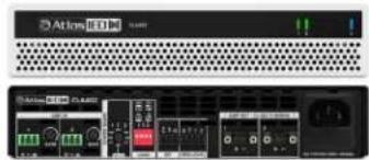
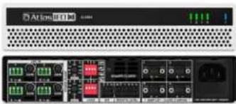
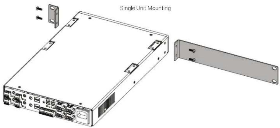
The CLA Series amplifier can be rack mounted as a single amp or side by side with any other AtlasIED 12 rack model. All parts to rack mount single or two amps are included with the CLA amp. Depending on the rack mounting method there may be extra part left; disregard them. Follow the illustrations below for kit assembly.
Kit Contains:
- Rack Ears Short, Qty 2
• Rack Ear to Chassis Screws M3 x 10mm, Qty 4
• Rack Ear Long for Single Unit Mounting, Qty 1
• Top & Bottom Chassis Joiner Plates, Qty 4 - 4-40 x 3/8 Flat Head Black Screws to Secure Joiner Plate to Chassis, Qty 16
• 10/32 x 1" Rack Mount Screws, Qty 4
• 10/32 Screw Plastic Washer, Qty 4
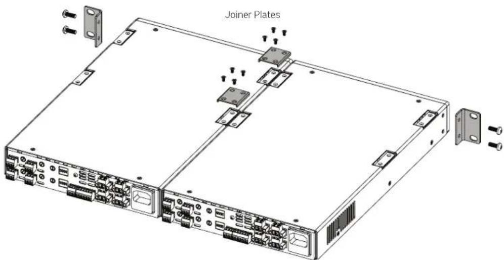
Dual Unit Mounting
CLA SERIES
COMMERCIAL LITE AMPLIFIERS
CLA804 / CLA404 / CLA802 / CLA402 / CLA202
OWNER'S MANUAL
System
| Type 2-Channel / 4-Channel Power Amplifier | |
| Power Supply Type Switch Mode - Wide Range 90 - 132V / 208 - 264V | |
| Amp Topology Class D | |
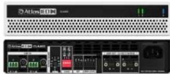
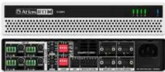
| Number of Fixed Inputs 2 for CLA202, CLA402, CLA802, 4 for CLA404, CLA804 | |
| DSP Internal No | |
| Network No | |
| Optional Card Slot No | |
Output Power (Note 1)
| Total Power Available 200W | ||||
| Power Share Configuration 100W / 100W 175W / 25W 150W / 50W 125W / 75W | ||||
| 4Ω, 8Ω, 70.7V, 100V 100W / 100W 175W / 25W 150W / 50W 125W / 75W | ||||
| 25V x 4 CH (Note 7) 2 x 100W 150W / 25W 150W / 50W 125W / 75W | ||||
| 2Ω x 4 CH (Note 8) | 2 x 50W | 90W / 12W | 75W / 25W | 65W / 38W |
Output Power (Note 1)
| Total Power Available 400W | ||||
| Power Share Configuration | 200W / 200W | 350W / 50W | 300W / 100W | 250W / 150W |
| 4Ω, 8Ω, 70.7V, 100V | 200W / 200W | 350W / 50W | 300W / 100W | 250W / 150W |
| 25V x 4 CH (Note 7) 2 x 150W 150W / 50W 150W / 100W | 150W / 150W | |||
| 2Ω x 4 CH (Note 8) | 2 x 100W 175W / 25W | 150W / 50W 125W / 75W | ||
Output Power (Note 1)
| Total Power Available 800W | ||||
| Power Share Configuration | 400W / 400W | 700W / 100W | 600W / 200W | 500W / 300W |
| 4Ω, 8Ω, 70.7V, 100V | 400W / 400W | 700W / 100W | 600W / 200W | 500W / 300W |
| 25V x 2 CH (Note 7) | 2 x 200W | 300W / 100W | 300W / 150W | 250W / 150W |
| 2Ω x 2 CH (Note 8) | 2 x 200W | 350W / 50W | 300W / 100W | 250W / 150W |
Output Power (Note 1)
| Total Power Available 400W | ||||
| Power Share Configuration | 100W / 100W x 2 | 175W / 25W x 2 | 150W / 50W x 2 | 125W / 75W x 2 |
| 4Ω, 8Ω, 70.7V, 100V | 100W / 100W x 2 | 175W / 25W x 2 | 150W / 50W x 2 | 125W / 75W x 2 |
| 25V x 4 CH (Note 7) | 4 x 100W | 150W / 25W x 2 | 150W / 50W x 2 | 125W / 75W x 2 |
| 2Ω x 4 CH (Note 8) | 4 x 50W | 90W / 12W x 2 | 75W / 25W x 2 | 65W / 38W x 2 |
CLA SERIES
COMMERCIAL LITE AMPLIFIERS
CLA804 / CLA404 / CLA802 / CLA402 / CLA202
OWNER'S MANUAL
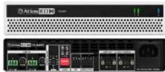
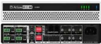
| Output Power (Note 1)Total Power Available 800W | CLA804 | |||
| Power Share Configuration 200W / 200W x 2 350W / 50W x 2 300W / 100W x 2 250W / 150W x 2 | ||||
| 4Ω, 8Ω, 70.7V, 100V | 200W / 200W x 2 | 350W / 50W x 2 | 300W / 100W x 2 | 250W / 150W x 2 |
| 25V x 4 CH (Note 7) | 4 x 150W | 150W / 50W x 2 | 150W / 100W x 2 | 150W / 150W x 2 |
| 2Ω x 4 CH (Note 8) | 4 x 100W | 175W / 25W x 2 | 150W / 50W x 2 | 125W / 75W x 2 |
| Factory Default Settings (As Shipped) | |
| Amplifier Configuration 2 CH & 4 CH | |
| Level Controls Rear Panel | |
| Control Ports (Rear Panel) Standby OFF, Priority Mute OFF | |
| Load Configurations 70V | |
| Power Share Configuration | CLA202 = 100W x 100W x 1, CLA402 = 200W x 200W x 1, CLA802 = 400W x 400W x 1, CLA404 = 100W x 100W x 2, CLA804 = 200W x 200W x 2 |
| Inputs | |
| Input Quantity Input Quantity 2 Balanced Inputs for | CLA202 and CLA402, 4 Balanced Inputs for CLA404 and CLA804 |
| Input Type Balanced Line | |
| Input Connectors Type 3.5mm Euro Block | |
| Input Impedance 20KΩ (Balanced) 10KΩ (Unbalanced) | |
| Input Sensitivity 1V (Fixed) | |
| Maximum Input Level dBu & Vrms 20dBu | |
| Level Control | |
| Rear Panel Rotary Detenled Attenuators | |
CLA SERIES
COMMERCIAL LITE AMPLIFIERS
CLA804 / CLA404 / CLA802 / CLA402 / CLA202
OWNER'S MANUAL
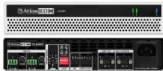
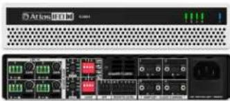
| Status Indicator - AC Mains / Power Supply, Multi-Color | |
| Idle Mode Blue Blinking | |
| Power On Mode Blue Steady | |
| Standby Mode Yellow Steady | |
| Protect Mode Red Steady | |
| AC Fault Red Blinking | |
| Thermal Protection Yellow Blinking | |
| Channel Status Indicators - 1 Per Channel, Multi-Color | |
| Ready for Use Clear (Off) | |
| Input Signal Green | |
| Output Limit Yellow Flashing | |
| Output Protect Red Steady | |
| Over Current / Fault Red | |
| Thermal Protection Yellow Steady | |
| GPIO Ports (Rear Panel) | |
| Number of Ports Qty 5 for CLA202 and CLA402, Qty | 7 for CLA404 and CLA804 |
| Type of Connector Euro Block 3.5mm | |
| Standby (Energy Save Mode) | Contact Closure Enables Standby |
| Priority Mute | Contact Closure Enables All Channel Mute |
| Remote Level Each Channel Has Remote Mute Port | |
| Configuration Settings (Rear Panel) | |
| Gain (Level) | Rotary Pot |
| Power Share | Rotary Switch |
| Output Terminals (Speaker) | |
| Output Connectors Type | Removable Euro Block, 5.08mm Pitch, Locking |
| Output Connectors Quantity | 2 Position, Qty 2 CLA202 and CLA402, Qty 4 CLA404 and CLA804 |
| Wire Size | 30-12 Gauge (Class 2 Wire) |
| Current Rating 12A RMS per Terminal | |
| Electrical Specifications (General) | |
| Total Harmonic Distortion 1 kHz and 1 dB Below Rated Power | ≤0.15% |
| Signal to Noise Ratio 80 | >93dBA Below Rated Output (A-Weighted) |
| Frequency Response | 20Hz - 20kHz (+0/-1.5dB) 2,4, 8-Ω, 25V Mode, 50Hz - 20KHz (+0/-1.5dB) 70V & 100V Mode |
| Input Impedance Balanced (Nominal) | 1000 Balanced Line to Line |
CLA SERIES
COMMERCIAL LITE AMPLIFIERS
CLA804 / CLA404 / CLA802 / CLA402 / CLA202
OWNER'S MANUAL
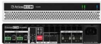
| Input Sensitivity 0.775V | |
| Slew Rate >18V/μs | |
| Damping Factor (20Hz to 400Hz) >250 | |
| Gain | CLA202 and CLA404 26dB 4Ω, 29dB 8Ω, 37dB 70V, 40dB 100V, CLA802 26dB 4, 29dB 8, 37dB 70V, 40dB 100V, CLA402 and CLA804 29dB 4Ω, 32dB 8Ω, 37dB 70V, 40dB 100V |
| Crosstalk CH 1-2 & CH 2-1 >70dB | |
| Max Voltage Per Output 100V Setting 101V | |
| Max Current Per Output 4Ω Setting | CLA202 and CLA404 9.4A @ 175W / CLA402 and CLA804 13.2A @ 350W |
| Protection | Soft Start, Input RF, DC, Short Circuit, Current Overload, Clip Limit, AC Mains Under / Over Voltage Shut Off, Peak Current Limit, Over Temp |
Cooling
| Cooling System Idle Mode is Convection, Audio Signal Sense (Fan, Variable with Temperature) | |
| Cooling Air Flow Direction Rear to Front, No Filters | |
| Fan Noise Idle 1M 0dBu (Fan is Off) | |
| Fan Noise Max 1M 42dBu | |
Environmental
| Operating Temperature 10° - 104°F (-12° - 40°C) | |
| Relative Humidity 0 - 95%, Non Condensing |
AC Power Requirements
| Operating Voltage 90V - 132V / 208V - 264V 50/60Hz, Auto Voltage Sense | |
| Mains Interface | IEC C14 |
| Power Cord (Included) | 1.8m, IEC C13 to NEMA 5-15 Plug, 16AWG |
| Minimum Power-Up Voltage | 90V |
| Maximum Operating Voltage | 264V |
OWNER'S MANUAL
| Power Consumption / Current Draw @ 120V AC Mains, Power Share Settings 100W x 2 | CLA202 | ||
| Amps Watts BTU / hr (Note 4) | |||
| Standby Mode, Meets Energy Star Standards 0.02A | 0.4W 1.35 BTU | ||
| Low Power Mode, Note 9 0.1A 10W 34 BTU | |||
| Idle Active 0.3A 18.6W 63 BTU | |||
| Average Power 2Ω, All CH Driven, Note 2, 8 0.6A 41W 139 BTU | |||
| Average Power 4Ω, All CH Driven, Note 2 | 0.5A 36W 122 BTU | ||
| Average Power 8Ω, All CH Driven, Note 2 | 0.5A 33W 112 BTU | ||
| Average Power 25V, All CH Driven, Note 2,7 | 0.5A 36W 122 BTU | ||
| Average Power 70V, All CH Driven, Note 2 | 0.4A 26W 88 BTU | ||
| Average Power 100V, All CH Driven, Note 2 | 0.4A 27W 92 BTU | ||
| Pink Noise Power 2Ω, All CH Driven, Note 3, 8 | 1.8A | 170W | 580 BTU |
| Pink Noise Power 4Ω, All CH Driven, Note 3 | 1.9A | 180W | 614 BTU |
| Pink Noise Power 8Ω, All CH Driven, Note 3 | 1.8A | 171W | 583 BTU |
| Pink Noise Power 25V, All CH Driven, Note 3, 8 | 1.8A | 164W 559 BTU | |
| Pink Noise Power 70V, All CH Driven, Note 3 | 1.6A | 125W 426 BTU | |
| Pink Noise Power 100V, All CH Driven, Note 3 | 1.6A | 129W 440 BTU | |
| Burst Power 2Ω, All CH Driven, Note 4, 8 | 1.3A 90W 307 BTU | ||
| Burst Power 4Ω, All CH Driven, Note 4 | 1.3A 91W 310 BTU | ||
| Burst Power 8Ω, All CH Driven, Note 4 | 1.3A 83W 283 BTU | ||
| Burst Power 25V, All CH Driven, Note 4, 7 1.3A 85W 290 BTU | |||
| Burst Power 70V, All CH Driven, Note 4 | 1.1A 77W 262 BTU | ||
| Burst Power 100V, All CH Driven, Note 4 1.1A 75W 255 BTU | |||
| Music Power 2Ω, All CH Driven, Note 5, 8 2.1A 198W 675 BTU | |||
| Music Power 4Ω, All CH Driven, Note 5 | 2.1A | 203W | 692 BTU |
| Music Power 8Ω, All CH Driven, Note 5 | 2.1A | 203W | 692 BTU |
| Music Power 25V, All CH Driven, Note 6, 8 2.1A 203W 692 BTU | |||
| Music Power 70V, All CH Driven, Note 5 | 1.9A | 191W 651 BTU | |
| Music Power 100V, All CH Driven, Note 5 | 1.8A | 187W 638 BTU | |
| Sine Wave Power 2Ω, All CH Driven, Note 6, 8 | 3.2A | 236W | 805 BTU |
| Sine Wave Power 4Ω, All CH Driven, Note 6 | 3.5A | 265W | 904 BTU |
| Sine Wave Power 8Ω, All CH Driven, Note 6 3.4A | 248W 846 BTU | ||
| Sine Wave Power 25V, All CH Driven, Note 6, 7 | 3.4A | 250W | 853 BTU |
| Sine Wave Power 70V, All CH Driven, Note 6 | 2.9A | 220W | 750 BTU |
| Sine Wave Power 100V, All CH Driven, Note 6 | 2.9A | 223W | 760 BTU |
OWNER'S MANUAL
| Power Consumption / Current Draw @ 120V AC Mains, Power Share Settings 200W x 2 | CLA402 | ||
| Amps Watts BTU / hr (Note 4) | |||
| Standby Mode, Meets Energy Star Standards 0.02A | 0.4W 1.35 BTU | ||
| Low Power Mode, Note 9 0.1A 10W 34 BTU | |||
| Idle Active 0.2A 11.7W 39 BTU | |||
| Average Power 2Ω, All CH Driven, Note 2, 8 0.5A 37W 126 BTU | |||
| Average Power 4Ω, All CH Driven, Note 2 0.8A 68W 232 BTU | |||
| Average Power 8Ω, All CH Driven, Note 2 0.8A 65W 221 BTU | |||
| Average Power 25V, All CH Driven, Note 2,7 0.7A 62W 211 BTU | |||
| Average Power 70V, All CH Driven, Note 2 | 0.7A 57W 194 BTU | ||
| Average Power 100V, All CH Driven, Note 2 | 0.7A 57W 194 BTU | ||
| Pink Noise Power 2Ω, All CH Driven, Note 3, 8 | 2.1A 189W 544 BTU | ||
| Pink Noise Power 4Ω, All CH Driven, Note 3 | 3.1A 251W 856 BTU | ||
| Pink Noise Power 8Ω, All CH Driven, Note 3 | 3.1A 248W 846 BTU | ||
| Pink Noise Power 25V, All CH Driven, Note 3, 8 | 2.9A 233W 795 BTU | ||
| Pink Noise Power 70V, All CH Driven, Note 3 | 3.0A 243W | 829 BTU | |
| Pink Noise Power 100V, All CH Driven, Note 3 | 3.0A 240W | 818 BTU | |
| Burst Power 2Ω, All CH Driven, Note 4, 8 | 1.0A | 125W | 426 BTU |
| Burst Power 4Ω, All CH Driven, Note 4 | 1.4A | 172W | 586 BTU |
| Burst Power 8Ω, All CH Driven, Note 4 | 1.2A | 139W | 474 BTU |
| Burst Power 25V, All CH Driven, Note 4, 7 1.4A 170W | 580 BTU | ||
| Burst Power 70V, All CH Driven, Note 4 | 1.1A 133W | 453 BTU | |
| Burst Power 100V, All CH Driven, Note 4 1.1A 126W | 429 BTU | ||
| Music Power 2Ω, All CH Driven, Note 5, 8 3.5A 295W | 1006 BTU | ||
| Music Power 4Ω, All CH Driven, Note 5 | 4.4A | 368W | 1255 BTU |
| Music Power 8Ω, All CH Driven, Note 5 | 4.4A | 368W | 1255 BTU |
| Music Power 25V, All CH Driven, Note 6, 8 4.2A 346W | 1180 BTU | ||
| Music Power 70V, All CH Driven, Note 5 | 4.2A 355W | 1211 BTU | |
| Music Power 100V, All CH Driven, Note 5 4.2A | 351W | 1197 BTU | |
| Sine Wave Power 2Ω, All CH Driven, Note 6, 8 | 4.5A | 362W | 1235 BTU |
| Sine Wave Power 4Ω, All CH Driven, Note 6 5.5A 457W | 1559 BTU | ||
| Sine Wave Power 8Ω, All CH Driven, Note 6 5.5A 442W | 1508 BTU | ||
| Sine Wave Power 25V, All CH Driven, Note 6, 7 5.2A | 428W | 1460 BTU | |
| Sine Wave Power 70V, All CH Driven, Note 6 | 4.9A 405W | 1381 BTU | |
CLA SERIES
COMMERCIAL LITE AMPLIFIERS
CLA804 / CLA404 / CLA802 / CLA402 / CLA202
OWNER'S MANUAL
| Power Consumption & Current Draw @ 120V AC Mains, Power Share Settings 400W x 2 | CLA802 | ||
| Amp Watts BTU / hr (Note 4) | |||
| Standby Mode, Meets Energy Star Standards 0.02A | 0.5W 1.7 | ||
| Low Power Mode - Note: 9 0.18A 10W 34 | |||
| Idle Active 0.24A 14W 47 | |||
| Average Power 2Ω, All CH Driven, Note 2, 8 1.09A 85W 290 | |||
| Average Power 4Ω, All CH Driven, Note 2 0.90A 67W | 228 | ||
| Average Power 8Ω, All CH Driven, Note 2 0.82A 61W | 208 | ||
| Average Power 25V, All CH Driven, Note 2,7 0.85A 68W 214 | |||
| Average Power 70V, All CH Driven, Note 2 0.82A 61W 208 | |||
| Average Power 100V, All CH Driven, Note 2 | 0.80A 59W | 201 | |
| Pink Noise Power 2Ω, All CH Driven, Note 3, 8 | 2.91A | 234W | 798 |
| Pink Noinse Power 4Ω, All CH Driven, Note 3 | 2.76A | 228W | 777 |
| Pink Noise Power 8Ω, All CH Driven, Note 3 | 2.65A | 216W | 737 |
| Pink Noise Power 25V, All CH Driven, Note 3, 8 | 2.62A | 216W | 737 |
| Pink Noise Power 70V, All CH Driven, Note 3 | 2.70A | 225W | 767 |
| Pink Noise Power 100V, All CH Driven, Note 3 | 2.30A | 192W | 655 |
| Burst Power 2Ω, All CH Driven, Note 4, 8 | 1.80A | 184W | 627 |
| Burst Power 4Ω, All CH Driven, Note 4 | 1.83A | 191W | 651 |
| Burst Power 8Ω, All CH Driven, Note 4 | 1.77A | 185W | 631 |
| Burst Power 25V, All CH Driven, Note 4, 7 1.75A | 182W | 621 | |
| Burst Power 70V, All CH Driven, Note 4 | 1.68A | 180W | 614 |
| Burst Power 100V, All CH Driven, Note 4 | 1.67A | 178W | 607 |
| Music Power 2Ω, All CH Driven, Note 5, 8 | 5.01A | 420W | 1433 |
| Music Power 4Ω, All CH Driven, Note 5 | 5.10A | 448W | 1528 |
| Music Power 8Ω, ALL CH Driven, Note 5 | 5.03A | 440W | 1502 |
| Music Power 25V, All CH Driven, Note 6, 8 | 5.03A | 432W | 1474 |
| Music Power 70V, All CH Driven, Note 5 | 5.04A | 435W | 1484 |
| Music Power 100V, All CH Driven, Note 5 | 4.96A | 425W | 1450 |
| Sine Wave Power 2Ω, All CH Driven, Note 6, 8 | 10.20A | 935W | 3190 |
| Sine Wave Power 4Ω, All CH Driven, Note 6 | 10.82A | 947W | 3231 |
| Sine Wave Power 8Ω, All CH Driven, Note 6 | 10.53A | 889W | 3033 |
| Sine Power 25V, All CH Driven, Note 6, 7 | 10.70A 928W | 3166 | |
| Sine WavePower 70V, All CH Driven, Note 6 | 10.30A 938W | 3200 | |
| Sine WavePower 100V, All CH Driven, Note 6 10.12A | 878W | 2995 | |
OWNER'S MANUAL
| Power Consumption / Current Draw@ 120V AC Mains,Power Share Settings 100W x 4 | CLA404 | ||
| Amps Watts BTU / hr (Note 4) | |||
| Standby Mode, Meets Energy Star Standards 0.02A | 0.4W 1.36 BTU | ||
| Low Power Mode, Note 9 0.1A 10W 34 BTU | |||
| Idle Active 0.4A 21W 71 BTU | |||
| Average Power 2Ω, All CH Driven, Note 2, 8 1.1A 82W | 279 BTU | ||
| Average Power 4Ω, All CH Driven, Note 2 1.1A 85W | 290 BTU | ||
| Average Power 8Ω, All CH Driven, Note 2 1.1A 83W | 283 BTU | ||
| Average Power 25V, All CH Driven, Note 2,7 1.1A 82W | 279 BTU | ||
| Average Power 70V, All CH Driven, Note 2 1.0A 78W | 266 BTU | ||
| Average Power 100V, All CH Driven, Note 2 | 1.0A 77W 262 BTU | ||
| Pink Noise Power 2Ω, All CH Driven, Note 3, 8 | 3.2A | 293W | 999 BTU |
| Pink Noise Power 4Ω, All CH Driven, Note 3 | 3.9A | 336W | 1146 BTU |
| Pink Noise Power 8Ω, All CH Driven, Note 3 | 3.9A | 325W | 1108 BTU |
| Pink Noise Power 25V, All CH Driven, Note 3, 8 | 3.9A | 330W | 1126 BTU |
| Pink Noise Power 70V, All CH Driven, Note 3 | 3.8A | 323W | 1102 BTU |
| Pink Noise Power 100V, All CH Driven, Note 3 | 3.6A | 316W | 1178 BTU |
| Burst Power 2Ω, All CH Driven, Note 4, 8 | 1.3A | 137W | 467 BTU |
| Burst Power 4Ω, All CH Driven, Note 4 | 1.5A | 155W | 528 BTU |
| Burst Power 8Ω, All CH Driven, Note 4 | 1.5A | 148W | 504 BTU |
| Burst Power 25V, All CH Driven, Note 4, 7 | 1.5A | 150W | 511 BTU |
| Burst Power 70V, All CH Driven, Note 4 | 1.4A | 141W | 481 BTU |
| Burst Power 100V, All CH Driven, Note 4 1.4A | 139W | 474 BTU | |
| Music Power 2Ω, All CH Driven, Note 5, 8 | 4.1A | 338W | 1153 BTU |
| Music Power 4Ω, All CH Driven, Note 5 | 4.2A | 347W | 1184 BTU |
| Music Power 8Ω, All CH Driven, Note 5 | 4.2A | 347W | 1184 BTU |
| Music Power 25V, All CH Driven, Note 6, 8 | 4.0A | 322W | 1098 BTU |
| Music Power 70V, All CH Driven, Note 5 | 4.1A | 339W | 1156 BTU |
| Music Power 100V, All CH Driven, Note 5 | 4.1A | 334W | 1139 BTU |
| Sine Wave Power 2Ω, All CH Driven, Note 6, 8 | 5.4A | 468W | 1596 BTU |
| Sine Wave Power 4Ω, All CH Driven, Note 6 | 5.9A | 483W | 1579 BTU |
| Sine Wave Power 8Ω, All CH Driven, Note 6 | 5.8A | 475W | 1620 BTU |
| Sine Wave Power 25V, All CH Driven, Note 6, 7 5.8A | 470W | 1603 BTU | |
| Sine Wave Power 70V, All CH Driven, Note 6 | 5.1A | 411W | 1402 BTU |
| Sine Wave Power 100V, All CH Driven, Note 6 | 5.2A | 427W | 1456 BTU |
CLA SERIES
COMMERCIAL LITE AMPLIFIERS
CLA804 / CLA404 / CLA802 / CLA402 / CLA202
OWNER'S MANUAL
| Power Consumption / Current Draw @ 120V AC Mains, Power Share Settings 200W x 4 | CLA804 | ||
| Amps Watts BTU / hr (Note 4) | |||
| Standby Mode, Meets Energy Star Standards 0.02A | 0.4W 1.36 BTU | ||
| Low Power Mode, Note 9 0.1A 10W 34 BTU | |||
| Idle Active 0.35A 18W 61BTU | |||
| Average Power 2Ω, All CH Driven, Note 2, 8 0.9A 83W 283 BTU | |||
| Average Power 4Ω, All CH Driven, Note 2 1.4A 108W | 368 BTU | ||
| Average Power 8Ω, All CH Driven, Note 2 1.1A 95W 324 BTU | |||
| Average Power 25V, All CH Driven, Note 2,7 | 1.2A 98W 334 BTU | ||
| Average Power 70V, All CH Driven, Note 2 | 1.2A 96W 327 BTU | ||
| Average Power 100V, All CH Driven, Note 2 | 1.2A 98W 334 BTU | ||
| Pink Noise Power 2Ω, All CH Driven, Note 3, 8 | 1.85A | 179W | 611 BTU |
| Pink Noise Power 4Ω, All CH Driven, Note 3 | 3.35A | 235W | 801 BTU |
| Pink Noise Power 8Ω, All CH Driven, Note 3 | 2.47A | 208W | 734 BTU |
| Pink Noise Power 25V, All CH Driven, Note 3, 8 | 3.08A | 215W | 738 BTU |
| Pink Noise Power 70V, All CH Driven, Note 3 | 3.2A 227W | 774 BTU | |
| Pink Noise Power 100V, All CH Driven, Note 3 | 3.2A 225W | 767 BTU | |
| Burst Power 2Ω, All CH Driven, Note 4, 8 | 1.30A | 138W | 470 BTU |
| Burst Power 4Ω, All CH Driven, Note 4 | 1.67A | 162W | 552 BTU |
| Burst Power 8Ω, All CH Driven, Note 4 | 1.26A | 131W | 446 BTU |
| Burst Power 25V, All CH Driven, Note 4, 7 1.62A | 160W | 545 BTU | |
| Burst Power 70V, All CH Driven, Note 4 | 1.71A | 168W | 168 BTU |
| Burst Power 100V, All CH Driven, Note 4 | 1.60A | 157W | 535 BTU |
| Music Power 2Ω, All CH Driven, Note 5, 8 | 4.85A | 390W | 1330 BTU |
| Music Power 4Ω, All CH Driven, Note 5 | 4.97A | 425W | 1450 BTU |
| Music Power 8Ω, All CH Driven, Note 5 | 4.97A | 425W | 1450 BTU |
| Music Power 25V, All CH Driven, Note 6, 8 | 4.50A | 396W | 1351 BTU |
| Music Power 70V, All CH Driven, Note 5 | 4.5A 406W | 1385 BTU | |
| Music Power 100V, All CH Driven, Note 5 4.5A 403W | 1375 BTU | ||
| Sine Wave Power 2Ω, All CH Driven, Note 6, 8 | 10.1A | 835W | 2849 BTU |
| Sine Wave Power 4Ω, All CH Driven, Note 6 | 12.1A | 971W | 3313 BTU |
| Sine Wave Power 8Ω, All CH Driven, Note 6 9.8A 822W | 2822 BTU | ||
| Sine Wave Power 25V, All CH Driven, Note 6, 7 | 10.3A 830W | 2832 BTU | |
| Sine Wave Power 70V, All CH Driven, Note 6 | 9.8A 802W | 2736 BTU | |
| Sine Wave Power 100V, All CH Driven, Note 6 | 9.6A 789W | 2692 BTU | |
CLA SERIES
COMMERCIAL LITE AMPLIFIERS
CLA804 / CLA404 / CLA802 / CLA402 / CLA202
| Power Cord IEC C13 Plug / 16AWG 1.8m Cord / NEMA 5-15 Plug | Qty 1 Qty 1 Qty 1 Qty 1 Qty 1 | |||
| Input Connector, 3 Position, 3.5mm Pitch Qty 2 Qty 2 Qty 4 Qty 4 | ||||
| GPI Connector, 3 Position, 3.5mm Pitch Qty 1 Qty 1 Qty 1 Qty 1 | ||||
| Remote Level Connector, 4 Position, 3.5mm Pitch Qty 1 Qty 1 Qty 1 Qty 0 Qty 0 | ||||
| Remote Level Connector, 6 Position, 3.5mm Pitch Qty 0 Qty 0 Qty 0 Qty 1 Qty 1 | ||||
| Speaker Connector, 2 Position, 5.08mm Pitch Qty 2 Qty 2 Qty 2 Qty 4 Qty 4 | ||||
| Rack Kit for Single & Dual Mounting | Qty 1 Qty 1 Qty 1 Qty 1 Qty 1 | |||
| Install Sheet with QR Code | Qty 1 Qty 1 Qty 1 Qty 1 Qty 1 |
Dimensions and Weight CLA202 CLA402 CLA802 CLA404 CLA804
| Rack Mount Requirements (All Models) | 12 Rack 8.5" | ||||
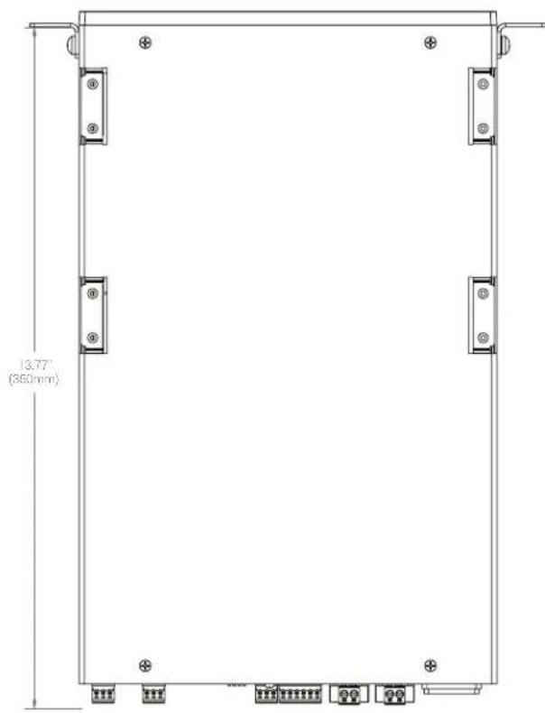
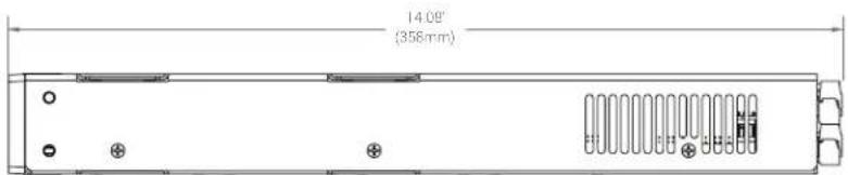
| Dimensions - Unit (All Models) | W 8.5" x H 1.75" x D 13.77" (216mm x 44mm x 350mm) | ||||
| Dimensions - Shipping (All Models) | W 17.25" x H 4.5" x D 11.75" (438mm x 114mm x 298mm) | ||||
| Weight - Unit | 6.5 lbs. / 3.0 kg | 7 lbs. / 3.2 kg. | 7.61 lbs. / 3.46 kg. | 8 lbs. / 3.64 kg. | 7.8 lbs. / 3.55 kg. |
| Weight - Shipping | 11.25 lbs. / 5.1 kg. | 11.75 lbs. / 5.34 kg. | 12.35 lbs. / 5.6 kg. | 12.75 lbs. / 5.8 kg. | 12.25 lbs. / 5.55 kg. |
Agency Approvals
| North America Agency | TUV |
| Testing Standard North America 62368-1 | |
| FCC Class A (Conducted & Radiated Emissions) | Part 15 B of the FCC Rules |
| RoHS / WEEE Compliant | Yes |
| CE | Yes |
OWNER'S MANUAL
NOTES:
- Power Level - Test is defined as follows: 1kHz sine wave signal burst of 20 cycles (20mS) at 1% THD+N, followed by 480 cycles of a 1kHz sine wave at 10% of the max power. Other power measurements available upon request. All power tests are done at 120V.
- Average power draw is defined as Pink Noise input signal applied to achieve 1/4 of the 40 or 70.7V power rating.
- Max pink noise power current draw is defined as Pink Noise applied as the signal source to the amplifier to achieve 100% of the 4Ω or 70.7V power rating. Using Pink Noise for testing amplifiers is a strenuous test that provides a consistent signal across the entire audio spectrum. Pink noise also provides a 6db Crest factor signal that injects a balance of RMS and peak signals providing realistic amp draw data for audio application.
- Max burst power draw is defined as follows: 1 kHz sine wave signal burst of 20 cycles (40mS) at 100% of the 4Ω or 70.7V power rating, followed by 480 cycles of a 1 kHz sine wave at 10% of the max power repeated. Note: The amp draw /watt data is the peak power consumed and not steady state amp draw. This complies the UL 62368-1 standard and testing for maximum peak amp draw for a 120v 15A AC mains.
-
Music power draw is defined as dynamic input signal applied to achieve the maximum rated power into a 40 or 70.7V load. This test also represents realistic current draw data for audio applications. The current draw data is the maximum peak amp / watt and not steady state amp draw. This complies the UL 62368-1 standard and testing for maximum peak amp draw for a 120V 15A AC mains. Note When specifying this amp for power consumption, we recommend using the Max Music Power Amps / Watt rating data.
-
Sine wave power draw is defined as 1 KHz input signal applied to achieve the maximum power output before clip into a 4Ω or 70.7V load. This data should be used as a reference of the maximum the current the amplifier can draw. The amount of time used to test was subject to exceeding the units circuit breaker provides this data thermal trip point. Note: The HPA2408 is designed and to be specified for paging and music program application. Steady state sine wave signals over 3 seconds should not be applied and may drip a 15A 120V AC Mains breaker.
- 25V System use 4 Ohm Load Selection Settings, CLA402 & CLA804 Power Share 200W Setting Equal 150W, CLA202 & CLA404 Power Share Setting 100W Equal 100W.
- 2-ohm loads use 4 Ohm Load Selection Settings, CLA402 & CLA804 Power Share 200W Setting Equal 100W, CLA202 & CLA404 Power Share 100W Setting Equal 50W.
- Low Power Mode: The Front panel AC Mains indicatore will blink Blue slowly. Fans are off and the power rails are lowered reducing power consumption. Signal flow is not interrupted or delayed.
OWNER'S MANUAL
| Power Consumption / Current Draw @ 230V AC Mains, Power Share Settings 100W x 2 | CLA202 | ||
| Amps Watts BTU / hr (Note 4) | |||
| Standby Mode 0.02A 0.5W 1.7 BTU | |||
| Low Power Mode, Note 9 0.1A 10W 34 BTU | |||
| Idle Active 0.2A 18W 61 BTU | |||
| Average Power 2Ω, All CH Driven, Note 2, 8 0.3A 36W 122 BTU | |||
| Average Power 4Ω, All CH Driven, Note 2 0.4A 45W 153 BTU | |||
| Average Power 8Ω, All CH Driven, Note 2 0.4A 42W 143 BTU | |||
| Average Power 100V, All CH Driven, Note 2 0.3A 31W 105 BTU | |||
| Pink Noise Power 2Ω, All CH Driven, Note 3, 8 | 1.4A | 160W | 545 BTU |
| Pink Noise Power 4Ω, All CH Driven, Note 3 | 1.5A | 173W | 590 BTU |
| Pink Noise Power 8Ω, All CH Driven, Note 3 | 1.4A | 168W | 573 BTU |
| Pink Noise Power 100V, All CH Driven, Note 3 | 1.0A | 112W | 382 BTU |
| Burst Power 2Ω, All CH Driven, Note 4, 8 | 0.9A | 102W | 348 BTU |
| Burst Power 4Ω, All CH Driven, Note 4 | 0.9A | 105W | 358 BTU |
| Burst Power 8Ω, All CH Driven, Note 4 | 0.8A 92W 313 BTU | ||
| Burst Power 100V, All CH Driven, Note 4 | 0.8A 90W | 307 BTU | |
| Music Power 2Ω, All CH Driven, Note 5, 8 | 1.5A | 194W | 661 BTU |
| Music Power 4Ω, All CH Driven, Note 5 | 1.5A | 197W | 672 BTU |
| Music Power 8Ω, All CH Driven, Note 5 | 1.5A | 197W | 672 BTU |
| Music Power 100V, All CH Driven, Note 5 | 1.1A | 109W | 371 BTU |
| Sine Wave Power 2Ω, All CH Driven, Note 6, 8 | 1.9A | 250W | 853 BTU |
| Sine Wave Power 4Ω, All CH Driven, Note 6 | 1.9A | 251W | 856 BTU |
| Sine Wave Power 8Ω, All CH Driven, Note 6 | 1.8A | 243W | 829 BTU |
| Sine Wave Power 100V, All CH Driven, Note 6 | 1.6A | 226W | 771 BTU |
| Power Consumption / Current Draw @ 230V AC Mains, Power Share Settings 200W x 2 | CLA402 | ||
| Amps Watts BTU / hr (Note 4) | |||
| Standby Mode 0.03A 0.5W 1.7 BTU | |||
| Low Power Mode, Note 9 0.1A | 9W | 30 BTU | |
| Idle Active 0.1A 18W 61 BTU | |||
| Average Power 2Ω, All CH Driven, Note 2, 8 0.4A 45W 153 BTU | |||
| Average Power 4Ω, All CH Driven, Note 2 0.5A 58W 197 BTU | |||
| Average Power 8Ω, All CH Driven, Note 2 0.5A 56W 191 BTU | |||
| Average Power 100V, All CH Driven, Note 2 0.4A 48W 163 BTU | |||
| Pink Noise Power 2Ω, All CH Driven, Note 3, 8 | 1.0A | 133W | 453 BTU |
CLA SERIES
COMMERCIAL LITE AMPLIFIERS
CLA804 / CLA404 / CLA802 / CLA402 / CLA202
OWNER'S MANUAL
| Pink Noise Power 4Ω, All CH Driven, Note 3 1.7A 247W 842 BTU | ||
| Pink Noise Power 8Ω, All CH Driven, Note 3 1.6A 238W 812 BTU | ||
| Pink Noise Power 100V, All CH Driven, Note 3 1.5A 231W 788 BTU | ||
| Burst Power 2Ω, All CH Driven, Note 4, 8 0.9A 156W 532 BTU | ||
| Burst Power 4Ω, All CH Driven, Note 4 1.1A 185W 631 BTU | ||
| Burst Power 8Ω, All CH Driven, Note 4 1.1A 182W 621 BTU | ||
| Burst Power 100V, All CH Driven, Note 4 0.9A 141W 481 BTU | ||
| Music Power 2Ω, All CH Driven, Note 5, 8 2.0A 298W 1016 BTU | ||
| Music Power 4Ω, All CH Driven, Note 5 2.2A 332W 1132 BTU | ||
| Music Power 8Ω, All CH Driven, Note 5 2.2A 332W 1132 BTU | ||
| Music Power 100V, All CH Driven, Note 5 2.1A 318W 1085 BTU | ||
| Sine Wave Power 2Ω, All CH Driven, Note 6, 8 2.3A 362W 1235 BTU | ||
| Sine Wave Power 4Ω, All CH Driven, Note 6 2.9A 451W 1538 BTU | ||
| Sine Wave Power 8Ω, All CH Driven, Note 6 2.8A 445W 1518 BTU | ||
| Sine Wave Power 100V, All CH Driven, Note 6 | 2.5A 391W 1334 BTU |
| Power Consumption & Current Draw @ 230V AC Mains, Power Share Settings 400W x 2 | CLA802 | ||
| Amps | Watts | BTU / hr (Note 4) | |
| Standby Mode | 0.03A | 0.5W | 1.7 |
| Low Power Mode - Note: 9 | 0.10A | 10W | 34 |
| Idle Active | 0.14A | 14W | 47 |
| Average Power 2, All CH Driven, Note 2, 8 | 0.65A | 77W | 262 |
| Average Power 4Ω, All CH Driven, Note 2 | 0.51A | 61W | 208 |
| Average Power 8Ω, All CH Driven, Note 2 | 0.42A | 55W | 187 |
| Average Power 100V, All CH Driven, Note 2 | 0.40A | 53W 180 | |
| Pink Noise Power 2Ω, All CH Driven, Note 3, 8 | 1.92A | 290W | 989 |
| Pink Noinse Power 4Ω, All CH Driven, Note 3 | 1.71A | 228W | 777 |
| Pink Noise Power 8Ω, All CH Driven, Note 3 | 1.60A | 215W | 733 |
| Pink Noise Power 100V, All CH Driven, Note 3 | 1.35A | 178W | 507 |
| Burst Power 2Ω, All CH Driven, Note 4, 8 | 1.16A | 167W | 569 |
| Burst Power 4W, All CH Driven, Note 4 | 1.27A | 185W | 631 |
| Burst Power 8Ω, All CH Driven, Note 4 | 1.22A | 181W | 617 |
| Burst Power 8Ω, All CH Driven, Note 4 | 1.22A | 181W | 617 |
| Burst Power 100V, All CH Driven, Note 4 1.22A | 180W | 614 | |
| Music Power 2Ω, All CH Driven, Note 5, 8 | 2.94A | 403W | 1375 |
| Music Power 4W, All CH Driven, Note 5 | 2.80A | 378W | 1289 |
CLA SERIES
COMMERCIAL LITE AMPLIFIERS
CLA804 / CLA404 / CLA802 / CLA402 / CLA202
OWNER'S MANUAL
| Music Power 8Ω, All CH Driven, Note 5, 8 2.94A 403W 1375 | ||
| Music Power 100V, All CH Driven, Note 5 2.65A 356W 1214 | ||
| Sine Wave Power 2Ω, All CH Driven, Note 6, 8 5.41A 837W 2855 | ||
| Sine Wave Power 4W, All CH Driven, Note 6 5.65A 891W 3040 | ||
| Sine Wave Power 8W, All CH Driven, Note 6 5.57A 856W 2920 | ||
| Sine WavePower 100V, All CH Driven, Note 6 5.15A 823W 2808 |
| Power Consumption / Current Draw @ 230V AC Mains, Power Share Settings 100W x 4 | CLA404 | ||
| Amps Watts BTU / hr (Note 4) | |||
| Standby Mode 0.03A 0.5W 1.7 BTU | |||
| Low Power Mode, Note 9 0.1A | 9W | 30 BTU | |
| Idle Active | 0.2A | 18W | 61 BTU |
| Average Power 2Ω, All CH Driven, Note 2, 8 | 0.6A | 85W | 290 BTU |
| Average Power 4Ω, All CH Driven, Note 2 | 0.6A | 84W | 286 BTU |
| Average Power 8Ω, All CH Driven, Note 2 | 0.6A | 82W | 279 BTU |
| Average Power 100V, All CH Driven, Note 2 | 0.5A | 71W | 242 BTU |
| Pink Noise Power 2Ω, All CH Driven, Note 3, 8 | 2.0A | 286W | 975 BTU |
| Pink Noise Power 4Ω, All CH Driven, Note 3 | 2.1A | 298W | 1016 BTU |
| Pink Noise Power 8Ω, All CH Driven, Note 3 | 2.1A | 295W | 1006 BTU |
| Pink Noise Power 100V, All CH Driven, Note 3 | 1.9A | 274W | 934 BTU |
| Burst Power 2Ω, All CH Driven, Note 4, 8 | 1.1A | 128W | 436 BTU |
| Burst Power 4Ω, All CH Driven, Note 4 | 1.2A | 142W | 484 BTU |
| Burst Power 8Ω, All CH Driven, Note 4 | 1.2A | 136W | 464 BTU |
| Burst Power 100V, All CH Driven, Note 4 | 1.0A | 113W | 385 BTU |
| Music Power 2Ω, All CH Driven, Note 5, 8 | 1.2A | 140W | 477 BTU |
| Music Power 4Ω, All CH Driven, Note 5 | 2.8A | 387W | 1320 BTU |
| Music Power 8Ω, All CH Driven, Note 5 | 2.8A | 387W | 1320 BTU |
| Music Power 100V, All CH Driven, Note 5 | 2.4A | 335W | 1143 BTU |
| Sine Wave Power 2Ω, All CH Driven, Note 6, 8 | 3.4A | 528W | 1801 BTU |
| Sine Wave Power 4Ω, All CH Driven, Note 6 | 3.2A | 469W | 1600 BTU |
| Sine Wave Power 8Ω, All CH Driven, Note 6 | 3.1A | 462W | 1576 BTU |
| Sine Wave Power 100V, All CH Driven, Note 6 2.8A | 414W | 1412 BTU | |
CLA SERIES
COMMERCIAL LITE AMPLIFIERS
CLA804 / CLA404 / CLA802 / CLA402 / CLA202
OWNER'S MANUAL
| Power Consumption / Current Draw @ 230V AC Mains, Power Share Settings 200W x 4 | CLA804 | ||
| Amps Watts BTU / hr (Note 4) | |||
| Standby Mode 0.03A 0.6W 2 BTU | |||
| Low Power Mode, Note 9 0.1A 9W 30 BTU | |||
| Idle Active 0.16A 18W 61 BTU | |||
| Average Power 2Ω, All CH Driven, Note 2, 8 0.48A 62W 211 BTU | |||
| Average Power 4Ω, All CH Driven, Note 2 | 0.58A 76W 259 BTU | ||
| Average Power 8Ω, All CH Driven, Note 2 | 0.52A 68W 232 BTU | ||
| Average Power 100V, All CH Driven, Note 2 | 0.62A 79W | 269 BTU | |
| Pink Noise Power 2Ω, All CH Driven, Note 3, 8 | 0.95A | 118W | 402 BTU |
| Pink Noise Power 4Ω, All CH Driven, Note 3 | 1.68A | 248W | 846 BTU |
| Pink Noise Power 8Ω, All CH Driven, Note 3 | 1.35A | 197W | 672 BTU |
| Pink Noise Power 100V, All CH Driven, Note 3 | 1.65A | 235W | 801 BTU |
| Burst Power 2Ω, All CH Driven, Note 4, 8 | 0.96A | 137W | 467 BTU |
| Burst Power 4Ω, All CH Driven, Note 4 | 1.59A | 182W | 621 BTU |
| Burst Power 8Ω, All CH Driven, Note 4 | 1.28A | 154W | 425 BTU |
| Burst Power 100V, All CH Driven, Note 4 | 1.42A | 168W | 573 BTU |
| Music Power 2Ω, All CH Driven, Note 5, 8 | 2.60A | 334W | 1139 BTU |
| Music Power 4Ω, All CH Driven, Note 5 | 2.68A | 362W | 1235 BTU |
| Music Power 8Ω, All CH Driven, Note 5 | 2.68A | 362W | 1235 BTU |
| Music Power 100V, All CH Driven, Note 5 | 2.54A | 336W | 1146 BTU |
| Sine Wave Power 2Ω, All CH Driven, Note 6, 8 | 4.76A | 711W | 2426 BTU |
| Sine Wave Power 4Ω, All CH Driven, Note 6 | 5.53A | 855W | 2917 BTU |
| Sine Wave Power 8Ω, All CH Driven, Note 6 | 4.98A | 728W | 2449 BTU |
| Sine Wave Power 100V, All CH Driven, Note 6 | 5.12A | 778W | 2654 BTU |
CLA SERIES
COMMERCIAL LITE AMPLIFIERS
CLA804 / CLA404 / CLA802 / CLA402 / CLA202
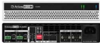
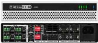
OWNER'S MANUAL
DIMENSIONAL DRAWINGS
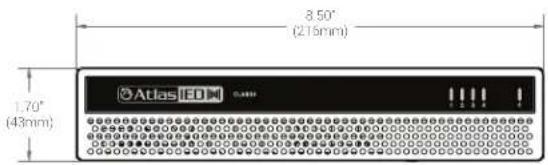
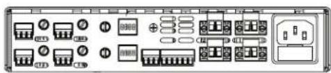
OWNER'S MANUAL
LIMITED WARRANTY
All products manufactured by AtlasIED are warranted to the original dealer / installer, industrial or commercial purchaser to be free from defects in material and workmanship and to be in compliance with our published specifications, if any. This warranty shall extend from the date of purchase for a period of three years on all AtlasIED products, including SOUNDOLIER brand, and ATLAS SOUND brand products except as follows: one year on electronics and control systems; one year on replacement parts; and one year on Musician Series stands and related accessories. Additionally, fuses and lamps carry no warranty. AtlasIED will solely at its discretion, replace at no charge or repair free of charge defective parts or products when the product has been applied and used in accordance with our published operation and installation instructions. We will not be responsible for defects caused by improper storage, misuse (including failure to provide reasonable and necessary maintenance), accident, abnormal atmospheres, water immersion, lightning discharge, or malfunctions when products have been modified or operated in excess of rated power, altered, serviced or installed in other than a workman like manner. The original sales invoice should be retained as evidence of purchase under the terms of this warranty. All warranty returns must comply with our returns policy set forth below. When products returned to AtlasIED do not qualify for repair or replacement under our warranty, repairs may be performed at prevailing costs for material and labor unless there is included with the returned product(s) a written request for an estimate of repair costs before any nonwarranty work is performed. In the event of replacement or upon completion of repairs, return shipment will be made with the transportation charges collect.
EXCEPT TO THE EXTENT THAT APPLICABLE LAW PREVENTS THE LIMITATION OF CONSEQUENTIAL DAMAGES FOR PERSONAL INJURY, ATLASIED SHALL NOT BE LIABLE IN TORT OR CONTRACT FOR ANY DIRECT, CONSEQUENTIAL OR INCIDENTAL LOSS OR DAMAGE ARISING OUT OF THE INSTALLATION, USE OR INABILITY TO USE THE PRODUCTS. THE ABOVE WARRANTY IS IN LIEU OF ALL OTHER WARRANTIES INCLUDING BUT NOT LIMITED TO WARRANTIES OF MERCHANTABILITY AND FITNESS FOR A PARTICULAR PURPOSE.
AtlasIED does not assume, or does it authorize any other person to assume or extend on its behalf, any other warranty, obligation, or liability. This warranty gives you specific legal rights and you may have other rights which vary from state to state.
SERVICE
Should your CLA Series Amplifier require service, please contact the AtlasIED warranty department through the online warranty claim process.
Online Warranty Claim Processes
- Warranty submissions are accepted at: https://www.atlasied.com/warranty_statement where the type of return Warranty or Stock return can be selected.
- .Once selected, you will be prompted to enter your login credentials. If you do not have a login, register on the site. If already logged-in, navigate to this page by selecting "Support" and then "Warranty & Returns" from the top menu.
- In order to file a Warranty Claim, you will need:
A copy of the invoice / receipt of the purchased item
B. Date of Purchase
C. The product name or SKU
D. The serial number for the item (if no serial number exists, enter N/A)
E. A brief description of the fault for the claim
- Once all required fields are completed, select the "Submit Button". You will receive 2 emails:
(1) with a confirmation of the submission
(2) with a case# for your reference should you need to contact us.
Please allow 2-3 business days for a response with a Return Authorization (RA) number and further instructions.
AtlasIED Tech Support can be reached at
1-800-876-3333
atlasied.com/support
Visit our website at www.AtlasIED.com to see other AtlasIED products.
- CLA SERIES
- OWNER'S MANUAL
- COMMERCIAL LITE AMPLIFIERS
- CLA804 / CLA404 / CLA802 / CLA402 / CLA202
- INTRODUCTION:
- AtlasIED AMPLIFIER POWER SHARE DESCRIPTION:
- KEY FEATURES:
- IMPORTANT SAFETY INSTRUCTIONS
- CAUTION - SHOCK RISK
- WARNING - WHEN THE DEVICE IS IN USE:
- CAUTION - WHEN INSTALLING THE PRODUCT:
- CAUTION - WHEN THE PRODUCT IS IN USE:
- FRONT PANEL
- VENTILATION / COOLING
- CHANNEL STATUS INDICATORS
- AC MAINS & POWER SUPPLY STATUS INDICATOR
- REAR PANEL
- AC MAINS INPUT
- BALANCE INPUT
- CHANNEL LEVEL CONTROLS
- GPI CONTROL PORT
- REAR PANEL - (CONTINUED)
- REMOTE LEVEL CONTROL PORT
- LOUDSPEAKER CONNECTION
- AMPLIFIER LOAD CONFIGURATION SWITCHES - IMPORTANT!
- Dip Switch Configuration:
- Channel 1 Load Selection Switch Positions:
- POWER SHARE SELECTION
- Power Share Selection Examples
- CABLING
- PLACEMENT OF THE AMP
- CLA GAIN vs INPUT SENSITIVITY
- LOW Z-GAIN
- HIGH Z-GAIN
- LO Z & HIGH Z-GAIN
- CONNECTING THE CLA AMPLIFIER TO AC MAINS
- DO NOT DO!
- CONNECTING THE CLA AMPLIFIER TO AC MAINS - (CONTINUED)
- Kit Contains:
- NOTES:
- LIMITED WARRANTY
- SERVICE
- Online Warranty Claim Processes
Brand : Atlas Sound
Model : CLA402
Category : Receiver