
CV-610-UB - Security Camera MARSHALL - Free user manual and instructions
Find the device manual for free CV-610-UB MARSHALL in PDF.


User questions about CV-610-UB MARSHALL
0 question about this device. Answer the ones you know or ask your own.
Ask a new question about this device
Download the instructions for your Security Camera in PDF format for free! Find your manual CV-610-UB - MARSHALL and take your electronic device back in hand. On this page are published all the documents necessary for the use of your device. CV-610-UB by MARSHALL.
USER MANUAL CV-610-UB MARSHALL
Full HD USB 2.0 PTZ Camera
natural_image
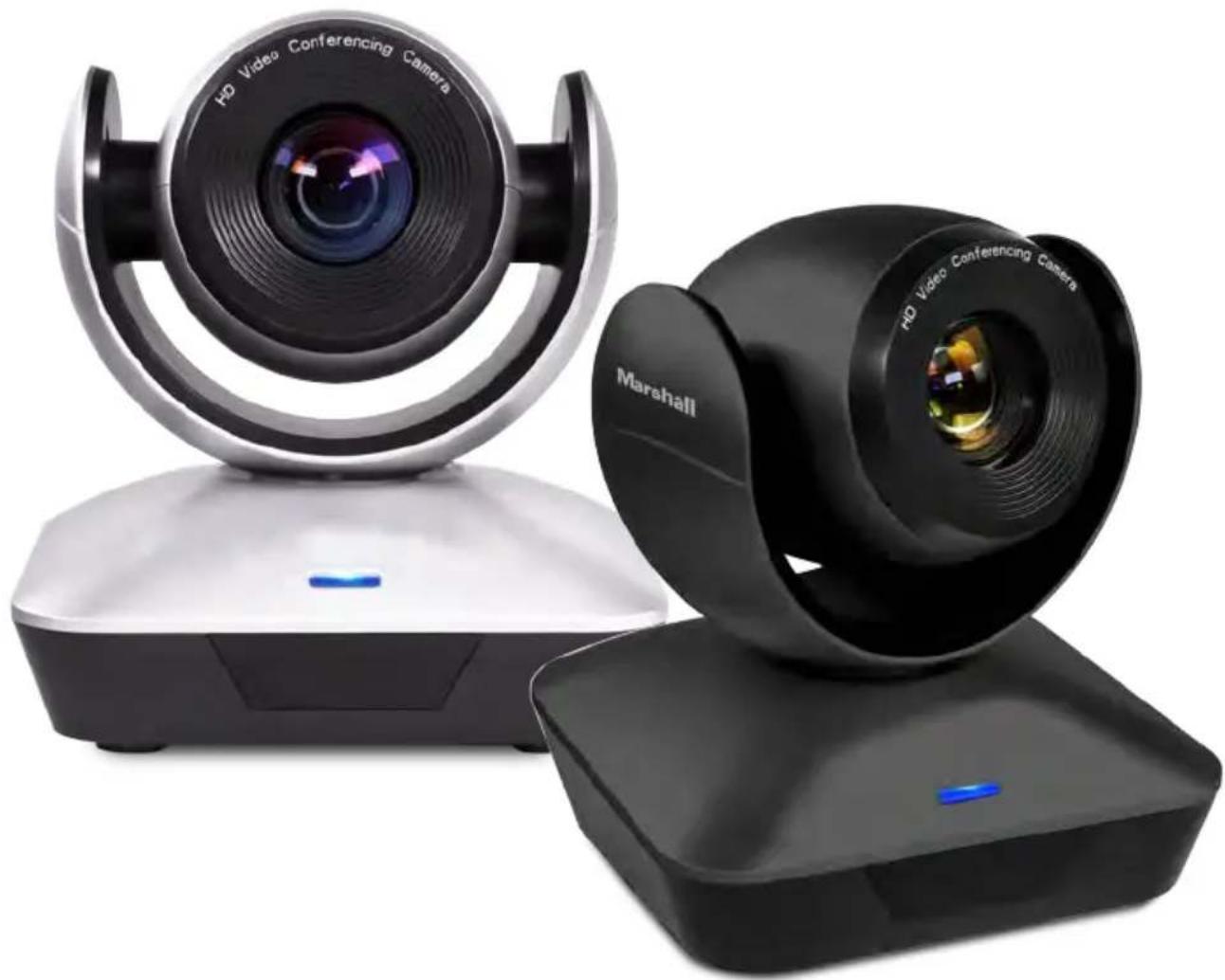
Two black HP video conferencing cameras on stands, one with lens and the other with a 'Marshall' logo (no text or symbols on devices)Operating Instructions
Version V3.6
Table of Contents
SAFETY GUIDELINES .... 3
ACCESSORIES 3
QUICK START 4
PRODUCTHIGHLIGHTS....5
RESOLUTION & FRAME RATE SETTINGS 5
CAMERASPECS....5
CAMERA INTERFACE 6
CAMERA DIMENSIONS 6
IR REMOTE CONTROLLER....7
OSD MENU 8
VISCA IN (RS232) PORT 1
IR TRANSFER (IR PASS) 1
UVC CONTROL....17
WALL MOUNT INSTALLATION....1

IMPORTANT SAFETY INSTRUCTIONS:
- Remove lens cover before plugging camera into power source.
- Before starting operation, please fully read and follow all instructions in the manual. For your safety, always keep this manual with the camera for reference.
- The camera power input range is 100-240VAC (50-60Hz), ensure the power supply input within this range before powering on.
- The camera power voltage is 12VDC, rated currency is 1.5A. We suggest you use it with the original power supply adapter supplied in the box.
- Please keep the power cable, video cable and control cable in a safe place. Protect all cables especially the connectors from moisture and dirt.
- Operational environment: 32^ to 122^ (0°C to 50°C) and humidity less than 90%. To avoid any danger, do not put anything inside the camera, and keep away from corrosive liquids.
- Avoid stress, vibration and jolts during transportation, storage and installation.
- Do not detach the camera housing and cover. For any service, please contact authorized technicians.
- RF cable and control cable should be individually shielded, and cannot be substituted with other cables. Do not direct the camera lens towards strong light, such as the sun or the intensive light.
- Always use a dry, soft cloth to clean the camera housing. Only use neutral cleaning agents when there is need to clean smudges or dirt from camera body. To avoid damage on the camera lens, only use a soft microfiber cloth.
- Do not carry or move the camera by holding the camera head. To avoid mechanical damage of internal gears, do not rotate the camera head by hand.
- Put the camera on a fixed desk or platform, avoid installing on surfaces that are not level.
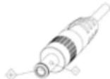
• Power Supply Polarity (Drawing) below:
INCLUDED IN THE BOX
- Power Adapter
- CV610-U2-WM - Wall Mount
- Power Cable
- RS232 Control Cable
- USB2.0 Cable
- Remote Controller (battery not included)
- Main Camera
QUICK START
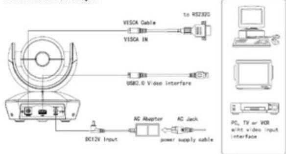
- REMOVE Lens Cover and check all cable connections to be sure they are all firmly connected before powering on
text_image
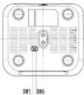
VISCA Cable to RS23G VISCA IN USK2.0 Video interfere DC12V Input AG Adapter AC Jack power supply cable PC, TV or VOR with video input interface- Dial Switch Setting (at the bottom of the camera):
text_image
SW1 SW6| DIP Switch (ARM) | ||
| SW-1 SW-2 Instruction | ||
| 1 OFF OFF Updating mode | ||
| 2 ON OFF Debugging mode | ||
| 3 OFF ON | Undefined | |
| 4 ON ON | Working mode | |
| DIP Switch (IR CODE TYPE) | ||
| SW-3 SW-4 Instruction | ||
| 1 OFF OFF Off(Close IR receiver) | ||
| 2 ON OFF | Undefined | |
| 3 OFF ON | SEJIN 4PPM CODE | |
| 4 ON ON | NEC CODE(standard) | |
| DIP Switch (USB) | ||
| SW-5 SW-6 Instruction | ||
| 1 OFF OFF | Undefined | |
| 2 ON OFF Working mode | ||
| 3 OFF ON | Updating mode | |
| 4 ON ON | Undefined | |
Note: Normal Working Mode: SW-1\~5: ON, SW-6: OFF
4 Marshall
PRODUCT HIGHLIGHTS
- Compact, ergonomically designed housing perfect for small huddle rooms or locations
- Supports advanced Ambarella DSP, 1/2.8 inch 5MP image sensor, and high quality 10X 62.5 degree FOV optical lens, provides crystal clear image quality
- Fast switching between different video formats: less than 1 second
• 10X Optical Zoom + 12X Digital Zoom
• Fast and accurate focus performance - Easy firmware upgrade - (field-upgradable)
• USB2.0 high speed output
• Effective RS232/485 serial control. Up to 128 presets
• Compatible with the majority of videoconferencing software (UVC1.5 protocol standard)
• Camera comes with accurate IR Remote Control unit - IR transfer/IR pass function: excepts signals from other codec's and IR remote control signals
CV610-U2 SPECIFICATIONS
| Video Format | MJPEG - 1080P30, 720P30, 640*480P30 |
| Video Port USB2.0 | |
| Sensor | 1/2.8 inch high quality 5MP CMOS sensor |
| Lens | F4.7~47,mm(10X), F1.8 - 14, Field of view: 62.5°(wide)-6.43°(tele) |
| Pan/tilt Rotation | Pan:±170°; Tilt:30°~+90°, support up-side down installation |
| Pan/tilt Speed Pans | 0.1°-120°/s; Tilt: 0.1° 80°/s |
| Preset | 10 via IR remote setting. 128 via VISCA control, preset accuracy :0.1° |
| Control Port | RS232, RS485, USB2.0 |
| Min. Lux | 0.01lux |
| White Balance AutoManual | |
| Focus | Auto/Manual |
| Iris | Auto/Manual |
| Shutter | Auto/Manual |
| WDR | Supported |
| BLC | Supported |
| 2D Noise Reduction | Supported |
| 3D Noise Reduction | Supported |
| Input Voltage | DC12V |
| Dimension | 148mm×132mm×161mm |
| Net weight | 0.9KG (2LBS) |
RESOLUTION & FRAME RATE SETTINGS
The Marshall CV610-U2 acts as a UVC command slave to Teleconference, U.C. or Video Capture Software programs that use it as a USB capture device. Once selected as an available camera, these software platforms send commands to camera as to compatible resolutions and frame rates based on bandwidth, software parameters, and/or computer capabilities. Some software platforms allow for direct adjust commands to change resolution and frame-rates, such as VLC Player and others. CV610-U2 adjusts as commanded by software platform or to nearest resolution settings available (1080p, 720p, 480p). There is no way to manually adjust resolutions and frame-rates from camera or camera OSD menu, since it relies on UVC (USB video class) commands. CV610-U2 adheres to UVC1.5 protocol standards.
CAMERA INTERFACE IR REMOTE CONTROLLER

text_image
Technical diagram of a device rear panel with labeled components and cross-sectional views- Camera Lens
- Camera Base
- IR Receiver Panel
- Indicator Light
- Dial Switch
- Tripod Screw Hole
- Installation Hole
- RS232 (MISCA INI Port
- H3252 (V150) 9. USB2.0 Port
- DC12V Power Input
- Power Indicator light (red)
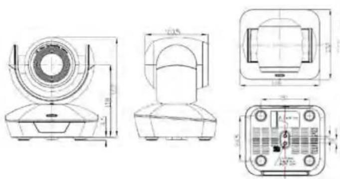
CAMERA DIMENSIONS (mm)
text_image
Technical drawing of a mechanical component with four orthographic views and dimension annotations
Marshall
text_image
CAM1 CAM2 CAM3 FOCUS HOME ZOOM MINI 1 2 3 4 5 6 7 8 9 0 Marshall
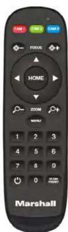
LED Function Instruction
Press any button and shows in red color: Current selection is to control CAM1;
Press any button and shows in green color: Current selection is to control CAM2;
Press any button and shows in blue color: Current selection is to control CAM3;
CAM1/CAM2/CAM3:
Long press(3seconds) to set camera address;
Short press to select camera address to control.
Focus: +/-
Manual focus, only valid under manual focus mode;
Zoom: +/-
Control the lens zoom rate;
Navigate : Up/Down/Left/Right
In normal working mode, use navigate key to control pan/tilt;
Or enter OSD menu, use navigate key to set parameters.
Confirm/Home button:
In normal working mode, short press to let the camera go back to
home position
Menu Button: Enter the OSD menu
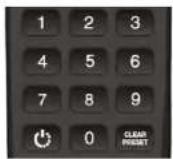
Number buttons
Set Preset: Long press(3seconds) the number button to save preset;
Clear Preset: +number button to clear the relative preset;
Long press(3seconds) the Clear button to clear all preset:
Short press 3 times to reset the lens focus:
Run Preset: Short press the number button to run the relative preset.

Short press to power on or off the camera
CV610-U2 OSD MENU EXPLAINED
1
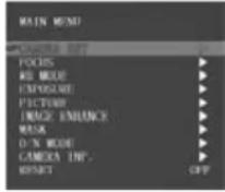
- Once camera is powered up and working, press the Menu button
on the IR remote control to enter the OSD menu (see pic.1); once changes are made press the OSD menu button again to exit and save modi efi parameters.
2
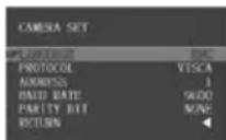
-
Use the navigate buttons (up/down/left/right) to choose which function to select. As picture 1 shows, once selection is made, the selected option will change to gray background highlight. Press the right navigate button to go to the sub menu (see pic.2).
-
In the sub menu, once again press the up/down navigate buttons to scroll and select, use left/right navigate button to cycle through selection options parameters.
- Select the last option "RETURN" and press the left navigate button to get back to main menu or previous menu.
- Press OSD button again to exit the menu.
- The following pages outline the Menu structure as it appears in OSD Menu:
| LANGUAGE Chinese/English | ||
| PROTOCOL VISCA/PELCO P/PELCO D | ||
| Camera Set | ADDRESS 1:7 | |
| BAUD RATE 2400,9500,115200 | ||
| PARITY BIT NONE | ||
| RETURN Back to the main menu | ||
| FOCUS | FOCUS MODE AUTO/MANUAL/PUSH | |
| SENSITIVITY LOW/MID/HIGH | ||
| FOCUS LIMIT 1.5M2M3M6M10M | ||
| D_ZOOM | OFF/ON | |
| ZOOM SPEED | 0-7 | |
| LENS INIT | OFF/5K/10K/15K/20K/EXE | |
| DIS ZOOM RATIO OFF/ON | ||
| RETURN Back to the main menu | ||
| WB MODE | WB MODE | ATWB/GAIN/TEMP./SOD,FL/AWB/IDR./ODR./PUSH |
| B_GAIN | 0~255 (Only Valid when WB MODE set to GAIN or TEMP.) | |
| R_GAIN | 0~255 (Only Valid when WB MODE set to GAIN or TEMP.) | |
| RETURN Back to the main menu | ||
| EXPOSURE | EXP MODE | AUTO/MANUAL/IRIS/SHUT/BRI. |
| SHUT TIME | Shutter time: 1/1-1/10K(Valid when EXP MODE set to MANUAL or SHUT) | |
| IRIS | Iris value: 0-13(Valid when EXP MODE set to MANUAL or IRIS) | |
| AGC | Gain value: 0dB~15dB(Valid when EXP MODE set to MANUAL) | |
| BRIGHT Brightness value: 0-27 (Valid when EXP MODE set to BRI.) | ||
| SLOW SHUT | OFF/ON | |
| FLICK | OFF/50HZ/60HZ(Valid when EXP MODE set to AUTO or IRIS) | |
| RETURN | Back to the main menu | |
| PICTURE | BRIGHTNESS | 1-15 |
| SHARPNESS | 0-15 | |
| CONTRAST | 0-15 | |
| SATURATION | 0-14 | |
| MIRROR | Image 180 degree rotation left/right: OFF/ON | |
| PIC FLIP | Image 180 degree rotation up/down: OFF/ON | |
| FREEZE OFF/ON | ||
| DEFOG | OFF/1-15 | |
| RETURN | Back to the main menu | |
| IMAGE ENHANCE | 2D NR | OFF/ON |
| 3D NR | OFF/AUTO' 1-4 | |
| D_WDR | OFF/1-6 | |
| GAMMA 0-4 | ||
| BACKLIGHT | OFF/ON | |
| HIGHLIGHT | OFF/ON | |
| RETURN | Back to the main menu | |
| MASK | MASK SWITCH | ON/OFF |
| COLOR | WHITE/YELLOW/GRAY/GREEN/VIOLET/RED | |
| INDEX | 1-8 | |
| INDEX SWITCH | OFF/ON | |
| ROW START 0-1919 | ||
| ROW END | 1-1920 | |
| LINE START | 0-1079 | |
| LINE END | 1-1079 | |
| RETURN | Back to the main menu | |
| D/N MODE | D/N MODE | DAY/NIGHT/AUTO |
| DAY TO NIGHT | 15-126 | |
| NIGHT TO DAY | 5-190 | |
| SWITCH DELAY | 1-60 | |
| GAIN LIMIT | 2-511 | |
| RETURN | Back to the main menu | |
| CAMERA INFO | IMAGE VER. | PC-V0.0.6 (change without notice) |
| IMAGE DATE | 16.10.20 (change without notice) | |
| CONTROL VER. | UC V0.1.4 (change without notice) | |
| CONTROL DATE | 17.01.07 (changes without notice) | |
| BAUDRATE 9600 | ||
| PARITY BIT NONE | ||
| RETURN | Back to the main menu | |
- All Button Sending Mode: long press (3 seconds) the Menu+ number "3" button simultaneously, the remote will enter all button sending mode.
- Similar operation for the TV control mode learning.
VISCA IN (RS232) PORT
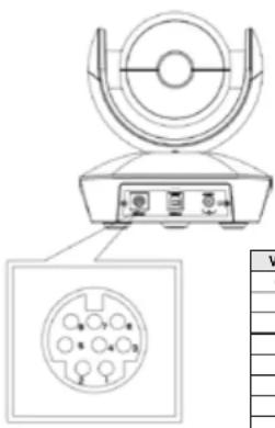
natural_image
Technical diagram of a mechanical device with a circular component and internal pinout, shown with an inset view (no text or symbols)| No. Function | |
| 1 DTR | |
| 2 DSR | |
| 3 TXD | |
| 4 GND | |
| 5 RXD | |
| 6 | A |
| 7 IR OUT | |
| 8 | B |
| VISCA IN &RS485 Connection | ||
| Camera VISCA IN RS485 | ||
| 1 DTR | ||
| 2 DSR | ||
| 3 TXD | ||
| 4 GND | ||
| 5 RXD | ||
| 6 A(+) | TX+ | |
| 7 IR OUT | ||
| 8 B(-) | TX- | |
| VISCA IN &DB9 Connection | |||
| Camera VISCA IN Windows DB-9 | |||
| 1 DTR | 6 | DSR | |
| 2 DSR | 4 | DTR | |
| 3 TXD | 2 | RXD | |
| 4 | GND | 5 | GND |
| 5 RXD | 3 | TXD | |
| 6 | A(+) | ||
| 7 | IR OUT | ||
| 8 | B(-) | ||
SERIAL PORT CONFIGURATION:
| Parameter | Value | Parameter | Value |
| Baud rate | 2400/9600/115200 | Stop Bit 1 bit | |
| Start Bit | 1 bit | Verify Bit | None |
| Date Bit | 8 bit |
VISCA PROTOCOL
Part 1 - Camera Return Command
| Ack/Completion Message | ||
| Command Packet | Note | |
| ACK | z0 41 FF | Returned when the command is accepted. |
| Completion | z0 51 FF | Returned when the command has been executed. |
| Error Messages | ||
| Command Packet | Note | |
| Syntax Error | 20 60 02 FF | Returned when the command format is different or when a command with illegal command parameters is accepted |
| Command Not Executable | z0 61 41 FF | Returned when a command cannot be executed due to current conditions. For example, when commands controlling the focus manually are received during auto focus. |
Part 2 - Camera Control Command
| Command | Funnation | Command Packet | Note |
| AddressSet | Broadcast | 88 30 01 FF | Address setting |
| IF_Clear | Broadcast | 88 01 00 01 FF | I/F Clear |
| CAM_Power | On | 8x 01 04 00 02 FF | Power ON/OFF |
| Off | 8x 01 04 00 03 FF | ||
| CAM_Zoom | Stop | 8x 01 04 07 00 FF | |
| Tele(Standard) | 8x 01 04 07 02 FF | ||
| Wide(Standard) | 8x 01 04 07 03 FF | ||
| Tele(Variable) | 8x 01 04 07 2p FF | p = 0(low)~7(high) | |
| Wide(Variable) | 8x 01 04 07 3p FF | ||
| Direct | 8x 01 04 47 0p 0q 0r 0s FF | pqrs: Zoom Position (0(wide) ~0x4000(tele)) | |
| CAM_Focus | Stop | 8x 01 04 08 00 FF | |
| Far(Standard) | 8x 01 04 08 02 FF | ||
| Near(Standard) | 8x 01 04 08 03 FF | ||
| Direct | 8x 01 04 48 0p 0q 0r 0s FF | pqrs: Focus Position | |
| One Push AF | 8x 01 04 18 01 FF | ||
| CAM_ZoomFocus | Direct | 8x 01 04 47 0p 0q 0r 0s 0t 0u 0v 0w FF | pqrs: Zoom Position (0(wide)~ 0x4000(tele)) tuvw: Focus Position |
| CAM_WB | Auto | 8x 01 04 35 00 FF | |
| Indoor | 8x 01 04 35 01 FF | ||
| Outdoor | 8x 01 04 35 02 FF | ||
| OnePush | 8x 01 04 35 03 FF | ||
| Manual | 8x 01 04 35 05 FF | ||
| Outdoor Auto | 8x 01 04 35 06 FF | ||
| Sodium Lamp Auto | 8x 01 04 35 07 FF | ||
| Sodium Auto | 8x 01 04 35 08 FF | ||
| CAM_RGain | Reset | 8x 01 04 03 00 FF | Manual Control of R Gain |
| Up | 8x 01 04 03 02 FF | ||
| Down | 8x 01 04 03 03 FF | ||
| Direct | 8x 01 04 43 00 00 0p 0q FF | pq: R Gain (0~0xFF) |
Part 2 - Camera Control Command
| Command Funnation | Command Packet | Note | |
| CAM_Bgain | Reset 8x 01 04 04 00 | FF Manual Control of B Gain | |
| Up 8x 01 04 04 02 FF | |||
| Down 8x 01 04 04 03 FF | |||
| Direct 8x 01 04 44 00 | 00 0p 0q FF pq: B Gain (0-0xFF) | ||
| CAM_AE | Full Auto 8x 01 04 39 | 00 FF Automatic Exposure mode | |
| Manual 8x 01 04 39 | 03 FF Manual Control mode | ||
| Bright 8x 01 04 39 00 | FF Bright mode(Manual control) | ||
| CAM_Shutter | Reset 8x 01 04 0A 00 | FF Shutter Setting | |
| Up 8x 01 04 0A 02 FF | |||
| Down 8x 01 04 0A 03 FF | |||
| Direct 8x 01 04 4A 00 | 00 0p 0q FF pq: Shutter Position (0~0x15) | ||
| CAM_Irrs | Reset 8x 01 04 0B 00 | FF | Iris SettingUp 8x 01 04 0B 02 FF |
| Down 8x 01 04 0B 03 FF | |||
| Direct 8x 01 04 4B 00 | 00 0p 0q FF pq: Iris Position (0~0x11) | ||
| CAM_Gain | Reset 8x 01 04 0C 00 | FF | Gain SettingUp 8x 01 04 0C 02 FF |
| Down 8x 01 04 0C 03 FF | |||
| Direct 8x 01 04 0C 00 | 00 0p 0q FF pq: Gain Position (0~0x0E) | ||
| CAM_Bright | Reset 8x 01 04 0D 00 | FF | Bright Setting |
| Up 8x 01 04 0D 02 FF | |||
| Down 8x 01 04 0D 03 FF | |||
| Direct 8x 01 04 4D 00 | 00 0p 0q FF pq: Bright I Position () | ||
| CAM_WDR | On | 8x 01 04 3D 02 FF | WDR ON/OFF |
| Off 8x 01 04 3D 03 FF | |||
| Direct 8x 01 04 D3 0p FF pq: WDR Position (1~0x06) | |||
| CAM_BackLight | On | 8x 01 04 33 02 FF BackLight On | |
| Off 8x 01 04 33 03 FF BackLight Off | |||
| CAM_Aperture | Reset 8x 01 04 02 00 FF | Aperture Control | |
| Up 8x 01 04 02 02 FF | |||
| Down 8x 01 04 02 03 FF | |||
| Direct 8x 01 04 42 00 | 00 0p 0q FF pq: Aperture Gain (0~0x04) | ||
| CAM_Memory | Reset 8x 01 04 3F 00 | 0p FF | p: Memory Number (=0 to 127)Corresponds to 0 to 9 on the Remote Commander |
| Set | 8x 01 04 3F 01 0p FF | ||
| Recall | 8x 01 04 3F 02 0p FF | ||
| CAM_LR_Reverse | On | 8x 01 04 61 02 FF | Image Flip Horizontal ON/OFF |
| Off 8x 01 04 61 03 FF | |||
| CAM_PictureFlip | On | 8x 01 04 66 02 FF | Image Flip Vertical ON/OFF |
| Off 8x 01 04 66 03 FF | |||
| CAM_ColorGain | Direct 8x 01 04 49 00 | 00 00 0p FF (0~0x0E) | |
| CAM_2D Noise Reduction | Direct 8x 01 04 53 0p FF 0::OFF 1:ON |
| Command Funnlation Command Packet | Note | ||
| CAM 3D Noise Reduction | Direct 8x 01 04 54 0 | o FF 0:OFF 1:AUTO 2~5: LEVEL | |
| FLICK | 50HZ | 81 01 04 23 01 FF | |
| 60HZ | 81 01 04 23 02 FF | ||
| Freeze | Freeze On | 81 01 04 62 02 FF | Freeze On Immediately |
| Freeze Off | 81 01 04 62 03 FF | Freeze Off Immediately | |
| Preset Freeze On | 81 01 04 62 22 FF | Freeze On When Running Preset | |
| Preset Freeze Off | 81 01 04 62 23 FF | Freeze Off When Running Preset | |
| IR_Transfer | Transfer On | 8x 01 06 1A 02 FF | Receive IR(remote commander) CODE from VISCA communication ON/OFF |
| Transfer Off | 8x 01 06 1A 03 FF | ||
| Pan_tiltDrive | Up 8x 01 06 01 VV WW 03 01 FF | VV: Pan speed 0x01 (low speed) to 0x18 (high speed)WW: Tilt speed 0x01 (low speed) to 0x14 (high speed)YYYY: Pan Position(TBD)ZZZZ: Tilt Position(TBD) | |
| Down 8x 01 06 01 VV WW 03 02 FF | |||
| Left | 8x 01 06 01 VV WW 01 03 FF | ||
| Right | 8x 01 06 01 VV WW 02 03 FF | ||
| Upleft 8x 01 06 01 VV WW 01 01 FF | |||
| Upright | 8x 01 06 01 VV WW 02 01 FF | ||
| DownLeft | 8x 01 06 01 VV WW 01 02 FF | ||
| DownRight | 8x 01 06 01 VV WW 02 02 FF | ||
| Stop | 8x 01 06 01 VV WW 03 03 FF | ||
| AbsolutePosition | 8x 01 06 02 VV WW0Y 0Y 0Y 0Y 0Z 0Z 0Z FF | ||
| RelativePosition | 8x 01 06 03 VV WW0Y 0Y 0Y 0Y 0Z 0Z 0Z FF | ||
| Home | 8x 01 06 04 FF | ||
| Reset 8x 01 06 05 FF | |||
| Pan-tiltLimitSet | Set | 8x 01 06 07 00 0W0Y 0Y 0Y 0Y 0Z 0Z 0Z FF | W:1 UpRight 0:DownLeftYYYY: Pan Limit Position(TBD)ZZZZ: Tilt Limit Position(TBD) |
| Clear | 8x 01 06 07 01 0W07 0F 0F 0F 07 0F 0F 0F FF | ||
Part 3 - Inquiry Command
| Command | Command Packet | Return Packet | Note |
| CAM_Powering | 8x 09 04 00 FF | y0 50 02 FF | On |
| y0 50 03 FF | Off(Standby) | ||
| CAM_ZoomPoslng | 8x 09 04 47 FF | y0 50 0p 0q 0r 0s FF | pqrs: Zoom Position |
| CAM_FocusModeling | 8x 09 04 38 FF | y0 50 02 FF | Auto Focus |
| y0 50 03 FF | Manual Focus | ||
| CAM_FocusPoslng | 8x 09 04 48 FF | y0 50 0p 0q 0r 0s FF | pqrs: Focus Position |
| CAM_WBModelIng 8x 09 04 | 35 FF | y0 50 00 FF Auto | |
| y0 50 01 FF Indoor mode | |||
| y0 50 02 FF Outdoor mode | |||
| y0 50 03 FF OnePush mode | |||
| y0 50 04 FF ATW | |||
| y0 50 05 FF Manual | |||
| CAM_RGainlng 8x 09 04 43 | FF y0 50 00 00 0p 0q FF pq: R Gain | ||
| CAM_BGainlng 8x 09 04 44 | FF y0 50 00 00 0p 0q FF pq: B Gain | ||
| CAM_AEmodeling 8x 09 04 39 | FF | y0 50 00 FF Full Auto | |
| y0 50 03 FF Manual | |||
| y0 50 0A FF Shutter priority | |||
| y0 50 0B FF Iris priority | |||
| y0 50 0D FF Bright | |||
| CAM_ShutterPoslng 8x 09 04 | 44A FF y0 50 00 00 0p 0q | FF pq: Shutter Position | |
| CAM_IrisPoslng 8x 09 04 48 | FF y0 50 00 00 0p 0q FF | pq: Iris Position | |
| CAM_GainPoslng | 8x 09 04 4C FF | y0 50 00 00 0p 0q FF | pq: Gain Position |
| CAM_BrightPoslng 8x 09 04 | 44D FF y0 50 00 00 0p 0q | FF pq: Bright Position | |
| CAM_ExpCompModeling | 8x 09 04 3E FF | y0 50 02 FF On | |
| y0 50 03 FF Off | |||
| CAM_ExpCompPoslng | 8x 09 04 4E FF | y0 50 00 00 0p 0q FF | pq: ExpComp Position |
| CAM_Aperturelng 8x 09 04 | 42 FF y0 50 00 00 0p 0q FF | pq: Aperture Gain | |
| CAM_Memorylng | 8x 09 04 3F FF y0 50pp FF | pp: Memory number last operated. | |
| SYS_MenuModeling | 8x 09 06 06 FF | y0 50 02 FF On | |
| y0 50 03 FF Off | |||
| CAM_LR_Reverseling | 8x 09 04 61 FF | y0 50 02 FF On | |
| y0 50 03 FF Off | |||
| CAM_PictureFlipling | 8x 09 04 66 FF | y0 50 02 FF On | |
| y0 50 03 FF Off | |||
| CAM_IDlng | 8x 09 04 22 FF | y0 50 0p 0q 0r 0s FF | pqrs: Camera ID |
| CAM_Versionlng | 8x 09 00 02 FF | y0 50 ab cd mn pq rs tu vw FF | |
| IR_Transfer | 8x 09 06 1A FF | y0 50 02 FF On | |
| y0 50 03 FF Off | |||
| Pan-tiltMaxSpeedlng | 8x 09 06 11 FF | y0 50 ww zz FF | ww: PanMaxSpeed zz: Tilt Max Speed |
| Pan-tiltPoslng | 8x 09 06 12 FF | y0 50 0w 0w 0w 0w 0z 0z 0z 0z FF | www: PanPosition zzzz: Tilt Position |
Note: (x) means the camera address; (y)=(x+8) .
VISCA PAN / TILT ABSOLUTE POSITION VALUE
| Pan Angle | VISCA Value | Tilt Angle | VISCA Value |
| -170 | 0xF670 | -30 | 0xFE50 |
| -135 | 0xF868 | 0 0x0000 | |
| -90 0xFAF0 | 30 | 0x01B0 | |
| -45 0xFD78 | 60 | 0x0360 | |
| 0 | 0x0000 | 90 0x510 | |
| 45 0x0288 | |||
| 90 0x0510 | |||
| 135 0x0798 | |||
| 170 0x0990 |
VISCA PAN / TILT ABSOLUTE POSITION VALUE
| Pan(degree/second) | Tilt(degree/second) | ||
| 0 | 0.3 | 0 | 0.3 |
| 1 1 | 1 | 1 | |
| 2 | 1.5 | 2 | 1.5 |
| 3 | 2.2 | 3 | 2.2 |
| 4 | 2.4 | 4 | 3.6 |
| 5 | 2.6 | 5 | 4.7 |
| 6 | 2.8 | 6 | 6 |
| 7 | 3.0 | 7 | 8 |
| 8 | 3.2 | 8 | 10 |
| 9 | 3.4 | 9 | 12 |
| 10 | 3.8 10 | 15 | |
| 11 | 4.5 11 | 18 | |
| 12 | 6 | 12 | 23 |
| 13 | 9 | 13 | 30 |
| 14 15 | 14 | 39 | |
| 15 19 | 15 | 48 | |
| 16 25 | 16 | 59 | |
| 17 32 | 17 | 69 | |
| 18 38 | 18 | 80 | |
| 19 45 | |||
| 20 58 | |||
| 21 75 | |||
| 22 88 | |||
| 23 | 105 | ||
| 24 | 120 | ||
| Shutter speed | 60/30mode | 50/25mode | Iris | |||
| 21 1/1 | 0000 1/10000 | 0 close | ||||
| 20 1/6 | 000 1/6000 1 | F14 | ||||
| 19 1/4 | 000 1/3500 2 | F11 | ||||
| 18 1/3 | 000 1/2500 3 | F9.6 | ||||
| 17 1/2 | 000 1/1750 4 | F8 | ||||
| 16 1/1 | 500 1/1250 5 | F6.8 | ||||
| 15 1/1 | 000 1/1000 6 | F5.6 | ||||
| 14 1/7 | 25 1/600 7 | F4.8 | ||||
| 13 1/5 | 00 1/425 8 | F4 | ||||
| 12 1/3 | 50 1/300 9 | F3.4 | ||||
| 11 1/2 | 50 1/215 10 | F2.8 | ||||
| 10 1/1 | 80 1/150 11 | F2.4 | ||||
| 9 | 1/125 1/120 | 12 F2 | ||||
| 8 | 1/100 1/100 | 13 F1.6 | ||||
| 7 | 1/90 | 1/75 | ||||
| 6 | 1/60 | 1/50 | ||||
| 5 | 1/30 | 1/25 | ||||
| 4 | 1/15 | 1/12 | ||||
| 3 | 1/8 | 1/6 | ||||
| 2 | 1/4 | 1/3 | ||||
| 1 | 1/2 | 1/2 | ||||
| 0 | 1/1 | 1/1 | ||||
| Gain | 0 | 0dB | Gain | 8 16dB | ||
| 1 | 2dB | 9 18dB | ||||
| 2 | 4dB | 10 20dB | ||||
| 3 | 6dB | 11 22dB | ||||
| 4 | 8dB | 12 24dB | ||||
| 5 | 10dB | 13 26dB | ||||
| 6 | 12dB | 14 28dB | ||||
| 7 | 14dB | 15 30dB | ||||
IR TRANSFER (IR PASS)
- Currently the camera support NEC code format. For customization with other codes, please contact us.
- Once the camera finish power configuration, enable the IR transfer function via sending COM command.
- Get the targeted remote controller point to the camera IR receiver, press keys on the remote controller,
then the camera will output the received IR code via VISCA IN port. - IR Transfer output format: XX XX XX XX FF
XX XX XX XX: Remote Controller Code
FF: End Code
- The camera can save all setting, no need to re-set after power circle.
UVC CONTROL
| Control Requests | Control Selector | |
| 1 | Brightness Control PU BRIGHTNESS | CONTROL |
| 2 | Contrast Control | PU CONTRAST CONTROL |
| 3 | Hue Control | PU_HUE_CONTROL |
| 4 | Saturation Control | PU_SATURATION_CONTROL |
| 5 | Sharpness Control | PU_SHARPNESS_CONTROL |
| 6 | Gamma Control | PU_GAMMA_CONTROL |
| 7 | White Balance Temperature Control | PU_WHITE_BALANCE_TEMPERATURE_CONTROL |
| 8 | Gain Control | PU_GAIN CONTROL |
| 9 | Power Line Frequency Control | PU_POWER_LINE FREQUENCY CONTROL |
| 10 | Zoom (Absolute) Control | CT_ZOOM_ABSOLUTE_CONTROL |
| 11 | Zoom (Relative) Control | CT_ZOOM_RELATIVE_CONTROL |
| 12 | PanTilt (Absolute) Control | CT_PANTILT_ABSOLUTE_CONTROL |
| 13 | PanTilt (Relative) Control | CT_PANTILT_RELATIVE_CONTROL |
- Secure the CV610-U2-WM to the wall with 4 M4 screws (included).
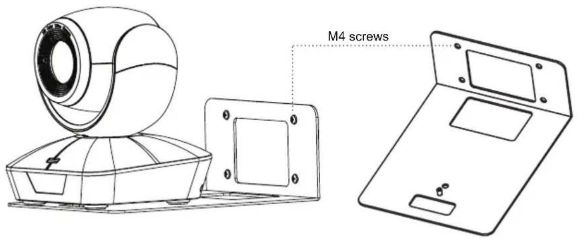
text_image
M4 screws- Disconnect all cables from the camera. Align the CV610-U2 camera's 14 -20UNC tripod screw hole with the wall mount screw hole. Use the 14 -20UNC screw (included) to secure the camera onto the wall mount. Reconnect the cables after mounting the camera.
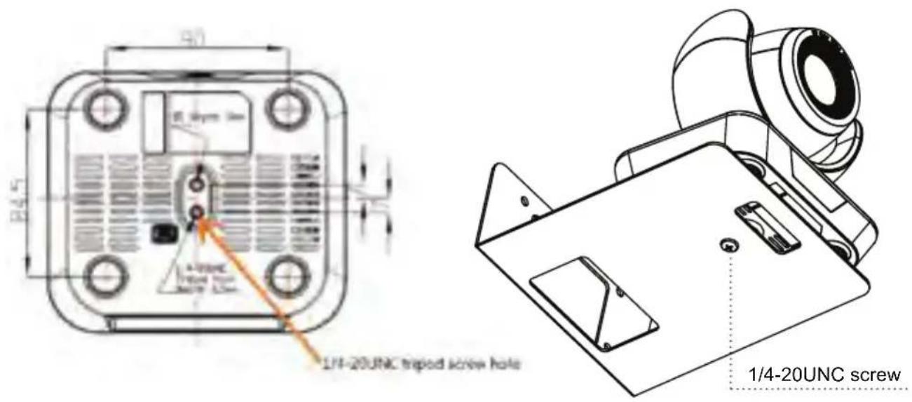
text_image
1/4-20UNC tripod screw hole 1/4-20UNC tripod screw hole 50 8/4.5 E Lymm 3m A-UNC Tropod Screw MOT 12mm 1/4-20UNC tripod screw hole 1/4-20UNC screwMarshall
Tel: (800) 800-6608 / (310) 333-0606 • Fax: 310-333-0688
www.marshall-usa.com
support@marshall-usa.com