
DS501 - Light effect machine DRAWMER - Free user manual and instructions
Find the device manual for free DS501 DRAWMER in PDF.


| Product Type | Dual Channel Noise Gate |
| Channels | 2 (independent or stereo linked) |
| Mounting | 19-inch rack, 1U |
| Input Connections | Balanced XLR (pin 2 hot, pin 3 cold, pin 1 ground) |
| Output Connections | Balanced XLR |
| Key Inputs | 1/4-inch TS jack (unbalanced) |
| Frequency Conscious Filters | Variable high-pass (25 Hz – 3 kHz) and low-pass (250 Hz – 30 kHz) |
| Envelope Controls | Attack (10 µs – 1 s), Hold (10 ms – 2.5 s), Decay (5 ms – 4 s), Range (0 dB to -80 dB) |
| Peak Punch | Adds up to 12 dB gain for ~10 ms; tunable (75 Hz – 16 kHz) or full band |
| Gate/Duck Mode | Switchable between gating and ducking |
| Threshold | -72 dBFS to infinity |
| Display | Traffic light LED (gate open, hold, closed) + signal below threshold meter |
| Key Listen / Bypass | Listen to filtered key signal; bypass routes input directly to output |
| Frequency Response | 23 Hz – 31 kHz (-1 dB) |
| Distortion (THD) | <0.025% at 100 Hz, 1 kHz, 10 kHz (0 dB input) |
| Noise (Gain ref 0 dB, gate open) | Wideband -90 dB, CCIR ARM -95 dB, IEC A -95 dB, Q-Pk CCIR -97 dB, AV -84 dB (RMS -88 dB) |
| Power Requirements | 93-125 V or 185-250 V AC, 50-60 Hz, 9 W |
| Fuse Rating | 80 mA for 230 V, 160 mA for 115 V; Class 3 time delay, 20x5 mm, IEC 60127-2 |
| Weight (packaged) | 3.4 kg |
| Dimensions (approx.) | 483 x 44 x 200 mm (19 x 1.75 x 7.9 in) |
| Warranty | 1 year limited (excluding misuse, modification) |
| Safety | Do not expose to rain/moisture; refer servicing to qualified personnel |
Frequently Asked Questions - DS501 DRAWMER
User questions about DS501 DRAWMER
0 question about this device. Answer the ones you know or ask your own.
Ask a new question about this device
Download the instructions for your Light effect machine in PDF format for free! Find your manual DS501 - DRAWMER and take your electronic device back in hand. On this page are published all the documents necessary for the use of your device. DS501 by DRAWMER.
USER MANUAL DS501 DRAWMER
IF A FAULT DEVELOPS page 11
CONTACTING DRAWMER page 11
TECHNICAL SPECIFICATION page 12
BLOCK DIAGRAM page 13
COPYRIGHT
This manual is copyrighted © 2001 by Drawmer Electronics, Ltd. With all rights reserved. Under copyright laws, this manual may not be duplicated in whole or in part without the written consent of Drawmer.
ONE YEAR LIMITED WARRANTY
Drawmer Electronics Ltd., warrants this product to conform substantially to the specifications of this manual for a period of one year from the original date of purchase when used in accordance with the specifications detailed in this manual. In the case of a valid warranty claim, your sole and exclusive remedy and Drawmer's entire liability under any theory of liability will be to, at Drawmer's discretion, repair or replace the product without charge, or, if not possible, to refund the purchase price to you. This warranty is not transferable. It applies only to the original purchaser of the product.
For warranty service please call your local Drawmer dealer. Alternatively call Drawmer Electronics Ltd. at +44 (0)1709 527574. Then ship the defective product, with transportation and insurance charges pre-paid, to Drawmer Electronics Ltd., Coleman Street, Parkgate, Rotherham, S62 6EL UK. Write the RA number in large letters in a prominent position on the shipping box. Enclose your name, address, telephone number, copy of the original sales invoice and a detailed description of the problem. Drawmer will not accept responsibility for loss or damage during transit.
This warranty is void if the product has been damaged by misuse, modification or unauthorised repair.
THIS WARRANTY IS IN LIEU OF ALL WARRANTIES, WHETHER ORAL OR WRITTEN, EXPRESSED, IMPLIED OR STATUTORY. DRAWER MAKES NO OTHER WARRANTY EITHER EXPRESS OR IMPLIED, INCLUDING, WITHOUT LIMITATION, ANY IMPLIED WARRANTIES OF MERCHANTABILITY, FITNESS FOR A PARTICULAR PURPOSE, OR NON-INFRINGEMENT. PURCHASER'S SOLE AND EXCLUSIVE REMEDY UNDER THIS WARRANTY SHALL BE REPAIR OR REPLACEMENT AS SPECIFIED HEREIN.
IN NO EVENT WILL DRAWMER ELECTRONICS LTD. BE LIABLE FOR ANY DIRECT, INDIRECT, SPECIAL, INCIDENTAL OR CONSEQUENTIAL DAMAGES RESULTING FROM ANY DEFECT IN THE PRODUCT, INCLUDING LOST PROFITS, DAMAGE TO PROPERTY, AND, TO THE EXTENT PERMITTED BY LAW, DAMAGE FOR PERSONAL INJURY, EVEN IF DRAWMER HAS BEEN ADVISED OF THE POSSIBILITY OF SUCH DAMAGES.
Some states and specific countries do not allow the exclusion of implied warranties or limitations on how long an implied warranty may last, so the above limitations may not apply to you. This warranty gives you specific legal rights. You may have additional rights that vary from state to state, and country to country.
In the interests of product development, Drawmer reserve the right to modify or improve specifications of this product at any time, without prior notice.

SAFETY CONSIDERATIONS

CAUTION - MAINS FUSE
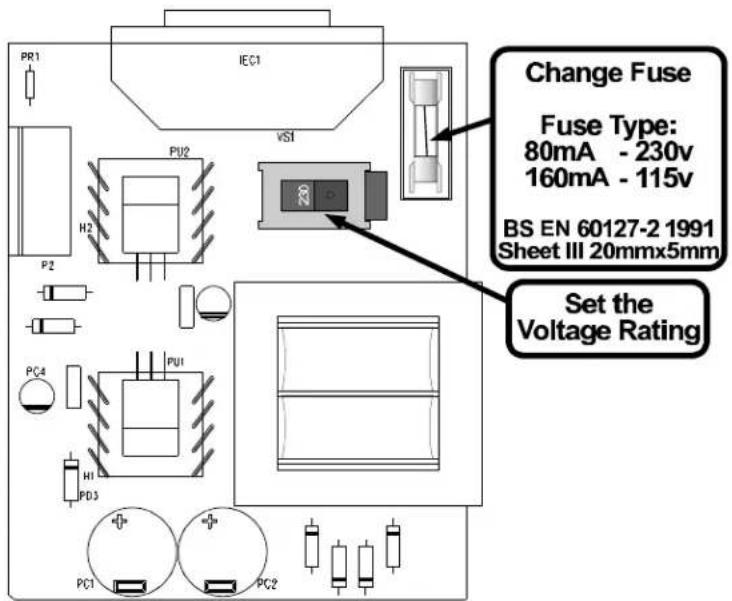
TO REDUCE THE RISK OF FIRE REPLACE THE MAINS FUSE ONLY WITH THE SAME TYPE, WHICH MUST BE A CLASS 3, 230 VOLT, TIME DELAY TYPE, RATED AT 80mA WHERE THE MAINS INPUT VOLTAGE SWITCH IS SET TO 230 VOLTS AC. AND 160mA WHERE THE MAINS INPUT VOLTAGE IS 115 VOLTS AC. ALL FUSES MUST COMPLY WITH IEC 60127-2. THE FUSE BODY SIZE IS 20mm x 5mm.
CAUTION - MAINS CABLE
DO NOT ATTEMPT TO CHANGE OR TAMPER WITH THE SUPPLIED MAINS CABLE.
CAUTION - SERVICING
DO NOT PERFORM ANY SERVICING. REFER ALL SERVICING TO QUALIFIED SERVICE PERSONNEL.
WARNING
TO REDUCE THE RISK OF FIRE OR ELECTRIC SHOCK DO NOT EXPOSE THIS EQUIPMENT TO RAIN OR MOISTURE.

CAUTION
RISK OF ELECTRIC SHOCK DO NOT OPEN

INSTALLATION
This product is designed for standard 19" rack mounting and occupies 1U of rack space. Use four M6 pan head screws to secure the unit into the rack. Fibre or plastic washers may be used to prevent the front panel becoming marked by the mounting bolts.
! Care should be taken in the choice of positioning. The unit should not be mounted where other equipment obstructs the normal air flow. Avoid mounting the unit directly above power amplifiers or power supplies that radiate significant amounts of heat.
! The DS501 should not be operated near any water or in a location where moisture might be present.
INTRODUCTION
The Drawmer DS501 is a sophisticated dual channel noise gate, which may be used as two independent channels or linked for true stereo operation. It incorporates a number of impressive features, many pioneered by Drawmer, which are invaluable to the sound engineer and not found on conventional noise gates:
! Variable high-pass and low-pass filters for 'frequency conscious' gating.
! Comprehensive envelope control, attack, hold, decay and range.
! Extremely low-noise and low-distortion circuitry.
! Ultra-fast response time.
! Comprehensive side-chain filtering.
! 'Key listen' facility.
! 'Traffic light' display giving clear indication of gate status.
! Signal below threshold indicator.
! Balanced inputs and outputs.
! Peak punch.
AUDIO CONNECTIONS
All input and output connectors are balanced XLRs, with the wiring convention being: pin 2 hot, pin 3 cold and pin 1 ground. For unbalanced operation, it is important to short pin 3 of the XLR connector to ground (pin 1) at both input and output.
Key inputs are made via 14 " mono jack connectors. If the Key jack sockets are permanently wired to a patch bay, it is important that the patch bay sockets are fully normalised to prevent random unwanted triggering.
If earth loop problems are encountered, never disconnect the mains earth but instead, try disconnecting the output signal screen at one end of the cables connecting the DS501 to the patchbay, we suggest inside the XLR connector itself. If such measures are necessary, balanced operation is recommended.

POWER CONNECTION
If the unit is to be operated at a mains input voltage which is different to that as supplied, the following must be carried out by a qualified technical engineer.
1: Disconnect the unit from the mains.
2: Using a number 1 size pozidrive screwdriver, remove the seven self-tapping screws that retain the top cover.
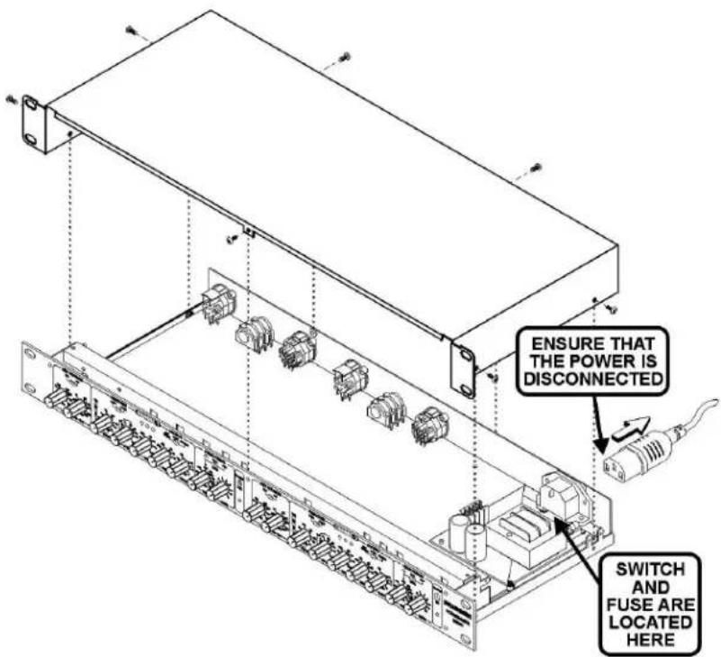
Accessing the internal power switch and fuse
-
Set the voltage rating and replace the fuse.
-
Replace the cover.
CONTROL DESCRIPTION
L.F. 25Hz - 3KHZ
The Low Frequency filter works by severely attenuating frequencies below the cut-off frequency selected.
H.F. 250Hz - 30KHz
The High Frequency filter attenuates frequencies above the selected cut-off value. In other words, when both filters are set, it is the range between the two settings that is allowed to pass.
Note: Filters only effect the signal triggering the gate. See 'KEY LISTEN'.
Ext/Int

In the Int position, this switch causes the gate to respond to the dynamics of the signal being processed. In the Ext position, an external audio signal fed to the key input is used to control the gate, making it possible to gate one sound using another, independent signal.
Threshold ! 72dBFs - Infinity
Sets the level at which the gate opens. The four led meter, to the left of the control, shows the signal below threshold.
Attack 10uS - 1 Second
This control determines how quickly the gate opens. The fastest Attack time ensures that the gate does not clip the leading edge of extremely fast transients. Note: See section on using Attack under 'OPERATION'.
Hold 10mS - 2.5 Second
Determines the amount of time the gate is held open after the signal falls below the Threshold.
Decay 5mS - 4 Second
Determines the rate at which the gate closes, once the signal has fallen below the Threshold and the Hold time has expired.
Range 0dB - !80dB
Sets the amount of attenuation applied to the signal when the gate is closed. This enables the gate to remove unwanted signals entirely, or simply to attenuate signals which are too loud. Note: Active on both channels, even in stereo linked operation
Gate/Duck Switches from normal Gating to Ducking, for applications such as voice-over or the removal of 'clicks' and 'pops'.
Note: See later sections on Ducking under 'OPERATION'.
Key Listen/
Gate/ Bypass

Key Listen allows the effect of the key filters on the programme material to be heard at the output.
Gate position is selected for normal use; the filters only affect the way the unit responds to the incoming programme material - they do not have any direct effect on the output signal.
Bypass position routes the input signal to the output with no processing.
Note: To use the DS501 as a filter instead of a gate leave the switch in the Key Listen position.
Display The famous Drawmer "traffic light" display shows gate status.

natural_image
Simple line drawing of five sun icons in a row, no text or symbols presentGate Closed Hold Time Gate Open
Peak Punch Adds gain to the leading edge of the envelope for a short duration. This adds considerable power to the gated signal. A filter option allows the user to tune the punch to a selected frequency for more subtle effects.
Note: See later section 'PEAK PUNCH.'
Filter/ Full Band/
Out OUT - Peak punch is not used.

FULL BAND - Only the "Level" knob is used. Tune is not used.
FILTER - Both "Tune" and "Level" knobs are used.
Tune 75 Hz - 16 kHz

Controls the frequency band to be "punched".
Level 1 - 10

Sets the Peak Punch level.
Stereo Link This switch links both channels for two tracking channel

operation, with channel one being master. The trigger source selected for channel one will actuate both channels' envelopes when this mode is selected.
OPERATION
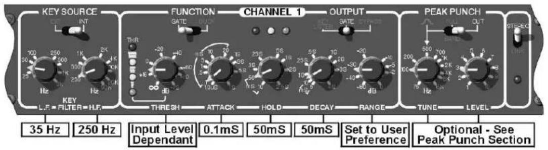
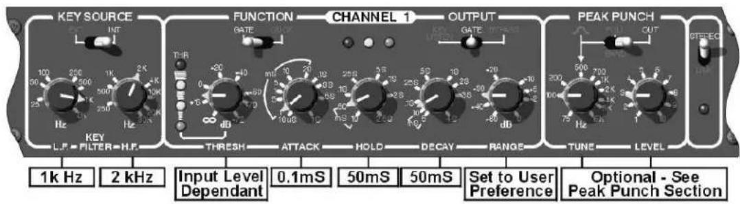
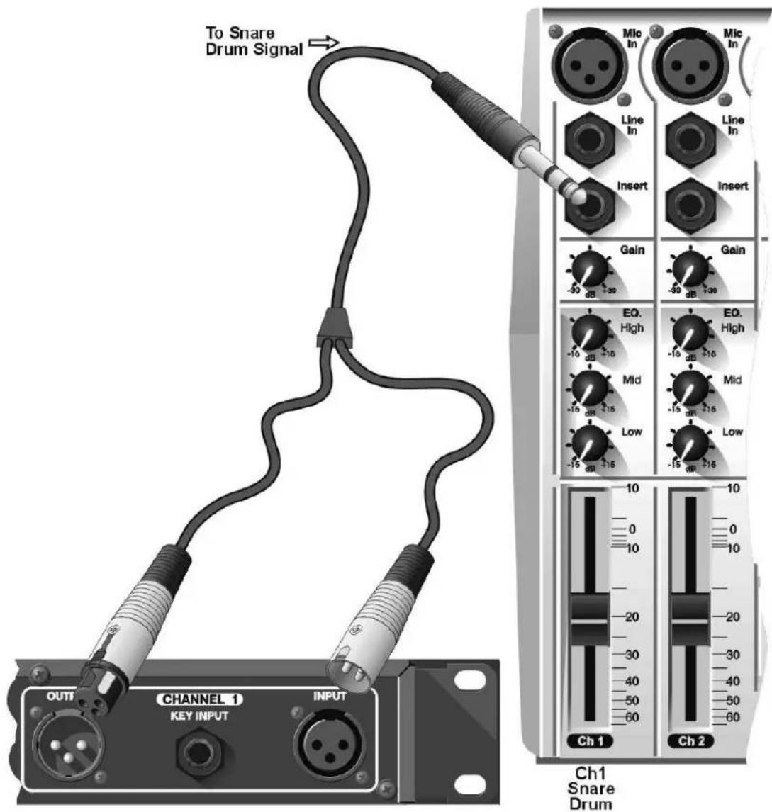
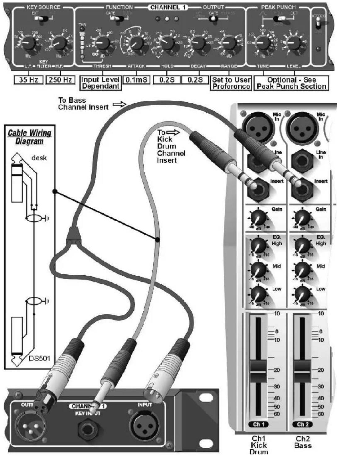
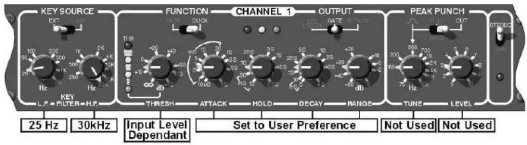
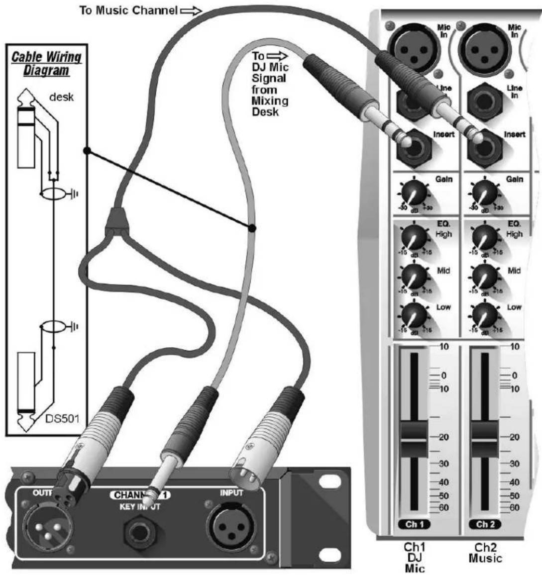
Use the following diagrams as a guide when operating the DS501.
Gating a Kick Drum.

Gating a Snare Drum.
Triggering a Bass Guitar from a Kick Drum.
Ducking Music from Vox.
PEAK PUNCH
Peak Punch is a dynamic feature which accelerates the leading edge as the gated signal opens, adding up to 12dB of gain for approximately 10mS with proprietary release characteristics.
For percussive material such as drums, fast synthesised sounds or percussive guitar, the Peak Punch mode of operation will give the most dramatic results.
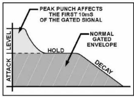
Care must be taken with material which has a slow attack (especially low frequency bass sounds), as the Peak Punch may produce transient clicks at the beginning of sounds, unless the attack knob is also slowed.
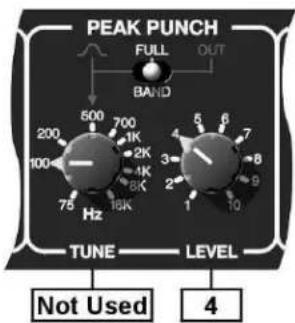
Filter section (TUNE) is not used in FULL BAND mode.
Set the peak punch LEVEL for added attack. Up to 12dB is available.
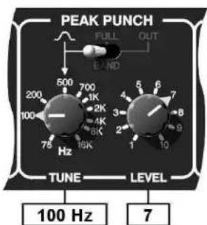
Using the filter to TUNE the punch.
Low pitch frequencies add depth.
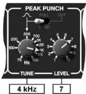
High punch frequencies could give a "rim shot" effect on a snare drum.
IF A FAULT DEVELOPS
For warranty service please call Drawmer Electronics Ltd. Or their nearest authorised service facility, giving full details of the difficulty. On receipt of this information, service or shipping instructions will be forwarded to you. No equipment should be returned under the warranty without prior consent from Drawmer or their authorised representative.
For service claims under the warranty agreement a service Returns Authorisation (RA) number will be given. Write this RA number in large letters in a prominent position on the shipping box. Enclose your name, address, telephone number, copy of the original sales invoice and a detailed description of the problem.
Authorised returns should be prepaid and must be insured. All Drawmer products are packaged in specially designed containers for protection. If the unit is to be returned, the original container must be used. If this container is not available, then the equipment should be packaged in substantial shock-proof material, capable of withstanding the handling for the transit.
CONTACTING DRAWMER
Drawmer Electronics Ltd., will be pleased to answer all application questions to enhance your usage of this equipment. Please address correspondence to:
Drawmer (Technical Help line) : Coleman St.: Parkgate : Rotherham : S62 6EL : UK
or, E-mail us on : tech@drawmer.co.uk
Drawmer dealers, Authorised service departments and other contact information can be obtained from our web pages on http://www.drawmer.com
TECHNICAL SPECIFICATIONS
(All measurements referenced to +4dBu operating level)
INPUT IMPEDANCE 20KS
MAXIMUM INPUT LEVEL + 17dB
OUTPUT IMPEDANCE 50S (bal)
MAXIMUM OUTPUT LEVEL + 17dB
BANDWIDTH 23Hz to 31KHz -1dB
NOISE AT UNITY GAIN ref 0dB, GATE open
| Wideband | 22Hz - 22KHz | CCIR ARM | IEC A | Q-Pk CCIR | |
| AV | ! 90dB | ! 95dB | ! 95dB | ! 97dB | ! 84dB |
| RMS | ! 88dB | ! 93dB | ! 93dB | ! 95dB |
DISTORTION
| 100Hz | 1KHz | 10KHz | |
| 0dB input | < 0.025% | < 0.025% | < 0.025% |
POWER REQUIREMENTS 93-125Volt or 185-250Volt at 50-60Hz, 9 Watts
FUSE RATING 80mA for 230Volt, 160mA for 115Volt
FUSE TYPE 20mm x 5mm, Class 3 Time delay, 250 Volt working. CONFORMING TO IEC 60127-2
WEIGHT (incl packaging) 3.4 Kgs
BLOCK DIAGRAM
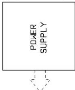
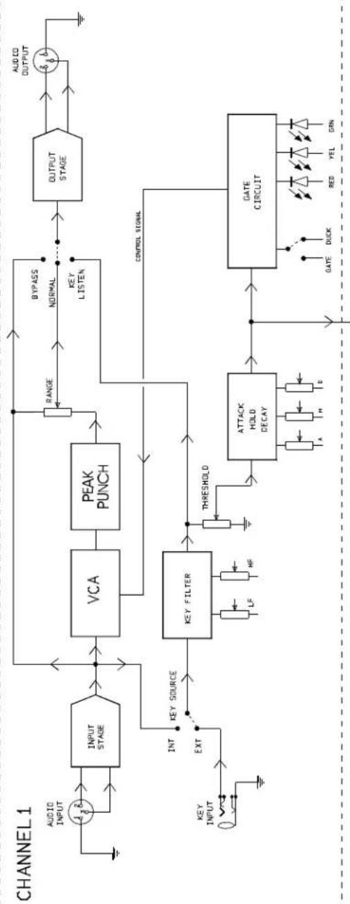
flowchart
graph TD
    A["CHANNEL 1"] --> B["INPUT STAGE"]
    B --> C["INPUT INPUT"]
    C --> D["OUTPUT STAGE"]
    D --> E["OUTPUT OUTPUT"]
    E --> F["OUTPUT OUTPUT"]
    F --> G["OUTPUT OUTPUT"]
    G --> H["OUTPUT OUTPUT"]
    H --> I["OUTPUT OUTPUT"]
    I --> J["OUTPUT OUTPUT"]
    J --> K["OUTPUT OUTPUT"]
    K --> L["OUTPUT OUTPUT"]
    L --> M["OUTPUT OUTPUT"]
    M --> N["OUTPUT OUTPUT"]
    N --> O["OUTPUT OUTPUT"]
    O --> P["OUTPUT OUTPUT"]
    P --> Q["OUTPUT OUTPUT"]
    Q --> R["OUTPUT OUTPUT"]
    R --> S["OUTPUT OUTPUT"]
    S --> T["OUTPUT OUTPUT"]
    T --> U["OUTPUT OUTPUT"]
    U --> V["OUTPUT OUTPUT"]
    V --> W["OUTPUT OUTPUT"]
    W --> X["OUTPUT OUTPUT"]
    X --> Y["OUTPUT OUTPUT"]
    Y --> Z["OUTPUT OUTPUT"]
    Z --> AA["OUTPUT OUTPUT"]
    AA --> AB["OUTPUT OUTPUT"]
    AB --> AC["OUTPUT OUTPUT"]
    AC --> AD["OUTPUT OUTPUT"]
    AD --> AE["OUTPUT OUTPUT"]
    AE --> AF["OUTPUT OUTPUT"]
    AF --> AG["OUTPUT OUTPUT"]
    AG --> AH["OUTPUT OUTPUT"]
    AH --> AI["OUTPUT OUTPUT"]
    AI --> AJ["OUTPUT OUTPUT"]
    AJ --> AK["OUTPUT OUTPUT"]
    AK --> AL["OUTPUT OUTPUT"]
    AL --> AM["OUTPUT OUTPUT"]
    AM --> AN["OUTPUT OUTPUT"]
    AN --> AO["OUTPUT OUTPUT"]
    AO --> AP["OUTPUT OUTPUT"]
    AP --> AQ["OUTPUT OUTPUT"]
    AQ --> AR["OUTPUT OUTPUT"]
    AR --> AS["OUTPUT OUTPUT"]
    AS --> AT["OUTPUT OUTPUT"]
    AT --> AU["OUTPUT OUTPUT"]
    AU --> AV["OUTPUT OUTPUT"]
    AV --> AW["OUTPUT OUTPUT"]
    AW --> AX["OUTPUT OUTPUT"]
    AX --> AY["OUTPUT OUTPUT"]
    AY --> AZ["OUTPUT OUTPUT"]
    AZ --> BA["OUTPUT OUTPUT"]
    BA --> BB["OUTPUT OUTPUT"]
    BB --> BC["OUTPUT OUTPUT"]
    BC --> BD["OUTPUT OUTPUT"]
    BD --> BE["OUTPUT OUTPUT"]
    BE --> BF["OUTPUT OUTPUT"]
    BF --> BG["OUTPUT OUTPUT"]
    BG --> BH["OUTPUT OUTPUT"]
    BH --> BI["OUTPUT OUTPUT"]
    BI --> BJ["OUTPUT OUTPUT"]
    BJ --> BK["OUTPUT OUTPUT"]
    BK --> BL["OUTPUT OUTPUT"]
    BL --> BM["OUTPUT OUTPUT"]
    BM --> BN["OUTPUT OUTPUT"]
    BN --> BO["OUTPUT OUTPUT"]
    BO --> BP["OUTPUT OUTPUT"]
    BP --> BQ["OUTPUT OUTPUT"]
    BQ --> BR["OUTPUT OUTPUT"]
    BR --> BS["OUTPUT OUTPUT"]
    BS --> BT["OUTPUT OUTPUT"]
    BT --> BU["OUTPUT OUTPUT"]
    BU --> BV["OUTPUT OUTPUT"]
    BV --> BW["OUTPUT OUTPUT"]
    BW --> BX["OUTPUT OUTPUT"]
    BX --> BY["OUTPUT OUTPUT"]
    BY --> BZ["OUTPUT OUTPUT"]
    BZ --> CA["OUTPUT OUTPUT"]
    CA --> CB["OUTPUT OUTPUT"]
    CB --> CC["OUTPUT OUTPUT"]
    CC --> CD["OUTPUT OUTPUT"]
    CD --> CE["OUTPUT OUTPUT"]
    CE --> CF["OUTPUT OUTPUT"]
    CF --> CG["OUTPUT OUTPUT"]
    CG --> CH["OUTPUT OUTPUT"]
    CH --> CI["OUTPUT OUTPUT"]
    CI --> CJ["OUTPUT OUTPUT"]
    CJ --> CK["OUTPUT OUTPUT"]
    CK --> CR["OUTPUT OUTPUT"]
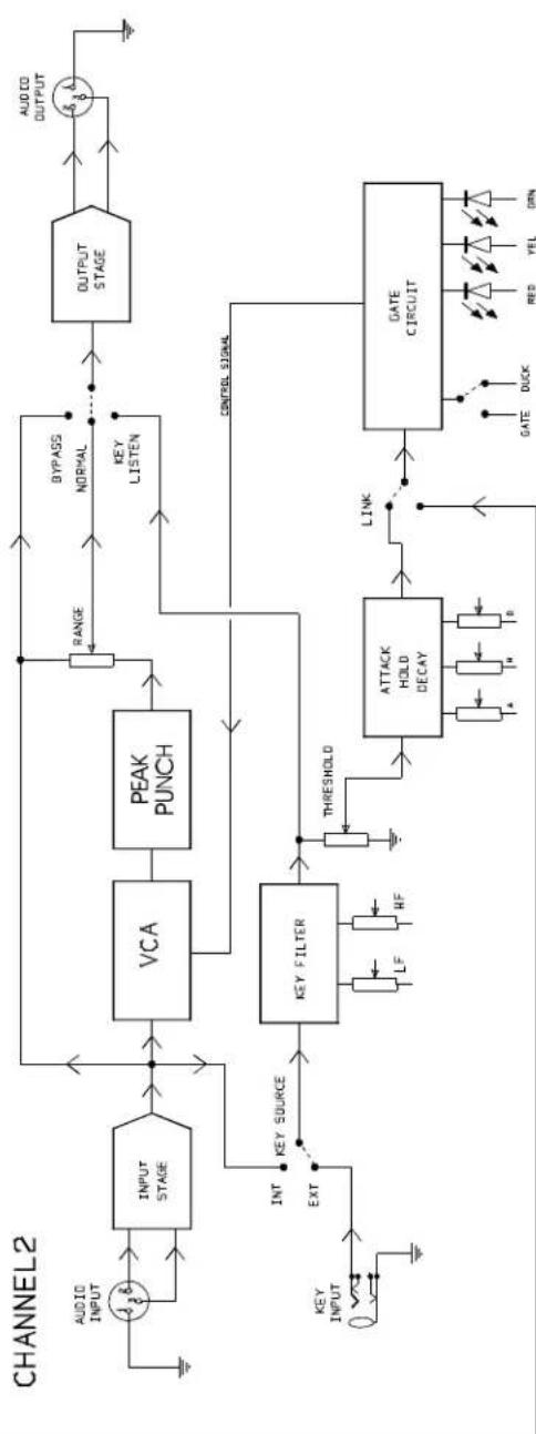
flowchart
graph TD
    A["OUTPUT STAGE"] --> B["PEAK PUNCH"]
    B --> C["VCA"]
    C --> D["KEY FILTER"]
    D --> E["INT KEY SOURCE"]
    E --> F["EXIT"]
    F --> G["INPUT STAGE"]
    G --> H["AUDIO INPUT"]
    H --> I["OUTPUT OUTPUT"]
    I --> J["CONTROL SIGNAL"]
    J --> K["KEY LISTEN"]
    K --> L["RANGE"]
    L --> M["BYPASS NORMAL"]
    M --> N["CONTROL SIGNAL"]
    N --> O["CONTROL SIGNAL"]
    O --> P["GATE CIRCUIT"]
    P --> Q["LINK"]
    Q --> R["THRESHOLD"]
    R --> S["RF"]
    S --> T["LF"]
    T --> U["INT KEY SOURCE"]
    U --> V["EXIT"]
    V --> W["INTERNATIONAL OUTPUT"]
    W --> X["OUTPUT OUTPUT"]
    X --> Y["OUTPUT OUTPUT"]
- COPYRIGHT
- ONE YEAR LIMITED WARRANTY
- SAFETY CONSIDERATIONS
- CAUTION - MAINS FUSE
- CAUTION - MAINS CABLE
- CAUTION - SERVICING
- WARNING
- CAUTION
- INSTALLATION
- INTRODUCTION
- AUDIO CONNECTIONS
- POWER CONNECTION
- CONTROL DESCRIPTION
- L.F. 25Hz - 3KHZ
- H.F. 250Hz - 30KHz
- Ext/Int
- Threshold ! 72dBFs - Infinity
- Attack 10uS - 1 Second
- Hold 10mS - 2.5 Second
- Decay 5mS - 4 Second
- Range 0dB - !80dB
- OPERATION
- PEAK PUNCH
- IF A FAULT DEVELOPS
- CONTACTING DRAWMER
- TECHNICAL SPECIFICATIONS
Brand : DRAWMER
Model : DS501
Category : Light effect machine