DTR-60.6 - Receiver Integra - Free user manual and instructions
Find the device manual for free DTR-60.6 Integra in PDF.


User questions about DTR-60.6 Integra
0 question about this device. Answer the ones you know or ask your own.
Ask a new question about this device
Download the instructions for your Receiver in PDF format for free! Find your manual DTR-60.6 - Integra and take your electronic device back in hand. On this page are published all the documents necessary for the use of your device. DTR-60.6 by Integra.
USER MANUAL DTR-60.6 Integra
Advanced Manual found here
http://Integraworldwide.com/manual/dtr606/adv/en.html

Before Start
About the Basic Manual
The Basic Manual leads you through the fundamental steps to enjoy the AV Receiver from connections to TV, speaker system and playback components, to necessary functions for playback. As well as that, Basic Manual informs you with the instructions on frequently used functions. Besides, there is another part of the manual called Advanced Manual to inform you with more detailed information, which we have decided to publish on the web from the ecological point of view.
Advanced Manual
Advanced Manual is always updated with the latest information and its user friendly interface, which does not matter whether you access from PC or Smartphone, helps you to understand more deeply about the AV Receiver. Advanced Manual is consisted of the following chapters.
• Details on AM/FM Playback
- Playing Music Files on a USB Storage Device
• Listening to Internet Radio
- Playing Music with DLNA
- Playing Music Files in a Shared Folder
• Operating Music Files with the Remote Controller
- Listening Mode
• Advanced Settings
- Operating Other Components with the Remote Controller
• Advanced Connection
• Connecting and Operating Onkyo RI Components
• Control Function between the Unit and External
- Firmware Update
- Troubleshooting
• Reference Information
Component

Advanced Manual found here
http://integraworldwide.com/manual/dtr606/adv/en.html
Features
• Equipped with 9 channel amplifier
• Supports playback in Dolby Atmos format which provides 360-degree placement and movement of sounds including overhead sound
• Dolby Surround listening mode expands 2 ch, 5.1 ch or 7.1 ch source to available speaker configurations
• THX Select2 Plus certified
• Incorporates Qdeo™ technology for HDMI video upscaling
• All HDMI jacks support displays of 4K resolution at 60 Hz
• Supports the HDMI Through function which allows transmission from playback devices to the TV in standby state
• Supports HDCP2.2, a strict copy-protection for providing high quality content (HDMI IN3/OUT MAIN only)
• Supports ARC (Audio Return Channel)
• Supports USB storage playback
• Supports variety of network functions such as Internet Radio, DLNA, etc.
• Supports MHL-enabled mobile device
• Bi-Amping capability
• A/V Sync function to correct deviation of audio and video
- Multi-zone function which allows you to play a different source in another room from the main room (Video can also be played in Zone 2)
• 32 bit DSP (Digital Signal Processor) with excellent calculation performance
- Music Optimizer™ for Compressed Digital Music files
- Phase Matching Bass System
• Automatic speaker setup available using supplied calibrated microphone (AccuEQ Room Calibration)
• Supports playback of MP3, FLAC, WAV, Ogg Vorbis, Apple Lossless, DSD via network and USB storage device (the supported formats will differ depending on the use environment)
• ISF (Imaging Science Foundation) Video Calibration
Supplied Accessories

Indoor FM antenna -- (1)

AM loop antenna --- (1)

Color labels for speaker cable --- (1)

Remote controller (RC-883M) --- (1) Batteries (AA/R6) --- (2)

Power cord --- (1)

Speaker setup microphone --- (1)
* The number in parenthesis indicates the quantity. On packaging, the letter at the end of the product name indicates the color.
How to use the remote controller
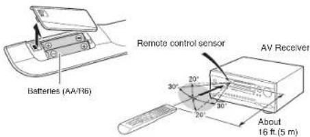
text_image
Batteries (AA/16) Remote control sensor AV Receiver About 16 ft.(5 m)* If you do not use the remote controller for a long time, remove the batteries to prevent leakage.
* Note that keeping consumed batteries inside may cause corrosion resulting in damage of the remote controller.
Step 1: Connections
flowchart
graph TD
    A["Personal computer"] -->|HDMI OUT| B["Game console"]
    A -->|HDMI cable| C["Set-top box/Digital video recorder, etc."]
    C -->|HDMI OUT| D["Satellite/Cable set-top box, etc."]
    D -->|HDMI OUT| E["Blu-ray Disc/DVD player"]
    E -->|HDMI IN| F["TV"]
    F --> G["HDMI 1.1 (STB/DVR)"]
    G --> H["ICBL/SAT"]
    H --> I["BO/DVD"]
    I --> J["OUT MAIN"]
    J --> K["HDMI 1.2 (ARC)"]
    K --> L["To use the ARC function, connect to the ARC compatible HDMI jack of the TV and make an appropriate setting on the unit. See '2nd Step : Source Connection' of "Step 2: Setting Up''"]
    style A fill:#f9f,stroke:#333
    style F fill:#ccf,stroke:#333
    style E fill:#cfc,stroke:#333
    style K fill:#fcc,stroke:#333
1 Connecting the TV and players
Important: The power cord must be connected only after all other connections are completed.
HDMI Cable Connection
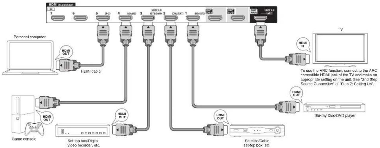
The unit has many HDMI jacks on its rear panel and each of them corresponds to an input selector button of the same name on the front panel. For example, a Blu-ray Disc player will be connected to the IN 1 jack and the BD/DVD button on the front panel will be used to listen to the playback sound (if the player is CEC compliant, input will be switched automatically). If you add another Blu-ray Disc player, you can use any other jack than IN 1. It is possible to change assignment of the input jacks and input selector buttons.
For how to make settings, see the Advanced Manual.
To connect the TV and the unit, connect the HDMI OUT MAIN jack of the unit and the HDMI IN jack of the TV using an HDMI cable. With this connection, it becomes possible to display the setting screen of the unit on the TV or transmit video/audio signals from the player to the TV. If your TV supports ARC (Audio Return Channel), it is possible to play the TV sound with the AV receiver's speakers with this connection only. If your TV does not support ARC, you need, in addition to the HDMI OUT MAIN jack connection, a digital optical cable connection between the digital audio out optical jack of the TV and the DIGITAL IN OPTICAL jack of the unit or an analog audio (RCA) cable connection between the audio output jack of the TV and the TV/CD analog audio input jack of the unit.
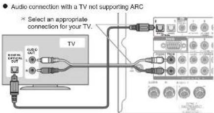
text_image
Audio connection with a TV not supporting ARC Select an appropriate connection for your TV. TV AUDIO OUT GENERAL OPTIONAL OUTAnother TV can be connected to the HDMI OUT SUB jack. In this case, press Monitor Out on the main unit several times to display "SUB" or "MAIN+SUB" and select the output method. You can also enjoy using Zone function with the HDMI OUT ZONE 2 jack. For details, see the section 6 "Using the multi-zone function" of "Step 3: Playing Back".
The unit supports the HDMI Through function that allows transmission from players to the TV even if the unit is in standby. You have to modify the settings to enable the input selection link with CEC compliant device, connection with ARC compatible TV, and HDMI Through function. See "2nd Step : Source Connection" of "Step 2: Setting Up".
• To enjoy HDCP2.2 protected video, connect the player to the IN3 jack and the TV to the HDMI OUT MAIN jack of the unit. Your player and TV need to support HDCP2.2.
• To play 4K or 1080p video, use the high speed HDMI cable.
- It is possible to send video and audio of an MHL-enabled mobile device by connecting the MHL-enabled mobile device to the AUX Input HDMI/MHL jacks on the front panel.
Connecting Components without HDMI
If your AV component does not have HDMI jack, use an available jack of your component for cable connection with this unit. Just as the HDMI jacks, other jacks on this unit have a preassigned input selector button on the front panel. See the name of the input selector button shown with the jack when connecting the device.
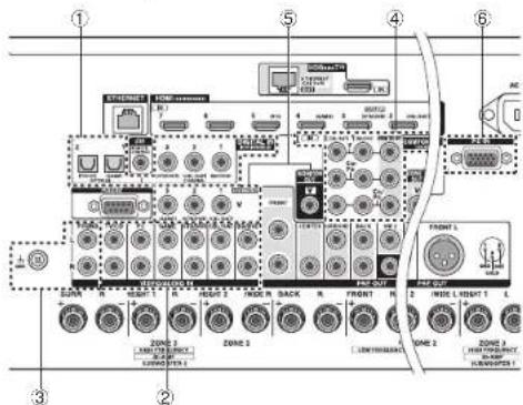
text_image
Labeled diagram of an electronic device rack with numbered components and ports■ Audio signal connection
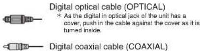
① Digital connection: Use a digital optical cable (OPTICAL) or digital coaxial cable (COAXIAL) for connection with a player.
text_image
Digital optical cable (OPTICAL) * As the digital in optical jack of the unit has a cover, push in the cable against the cover as it is turned inside. Digital coaxial cable (COAXIAL)② Analog connection: Use an analog audio (RCA) cable for connection with a player.
To enjoy multi-zone playback of audio of a CD player or such other player without HDMI output jack, you need to use the analog audio (RCA) cable to connect the corresponding jacks of the player and this unit. For details on the multi-zone function, see the section 6 "Using the multi-zone function" of "Step 3: Playing Back".

③ Connection with turntable: If it uses an MM type cartridge and does not have a built-in audio equalizer, connect it to the ③ PHONO jack. If the connected turntable has a built-in audio equalizer, connect it to the
② TV/CD jack. * If it uses an MC type cartridge, install an audio equalizer compatible with MC type cartridge between the unit and the turntable by connecting it to the ② TV/CD jack. For details, refer to the turntable's instruction manual. * If the turntable has a ground wire, connect it to the GND terminal of this unit. If connecting the ground wire increases noise, disconnect it.
■ Video signal connection
The unit has a video upconversion function. For details, see the section on the right.
④ Use a component video cable to connect a TV with component video input jacks and a player with component video output jacks.

Component video cable * Its transmitted video has higher quality than that of composite video cable.
⑤ Use a composite video cable to connect a TV with composite video input jack or a player with composite video output jack.
Composite video cable
⑥ Use an analog RGB cable to connect the unit with a PC.

* Video signals from the PC connected with the PC IN port will be output only to a TV connected with the HDMI OUT MAIN/SUB/ZONE 2 jack.
Video signals input to the composite video input jack, the COMPONENT VIDEO input jack, or the PC IN port will be upconverted to HDMI signals and then output from the HDMI output jack. Note that it is not possible to convert digital audio input signals to analog or vice versa.
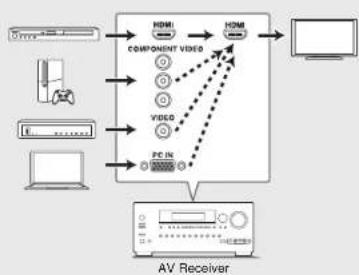
flowchart
graph TD
    A["Computer"] --> B["Component Video"]
    B --> C["Video"]
    C --> D["PC"]
    D --> E["AV Receiver"]
    F["Video"] --> G["Component Video"]
    G --> H["Video"]
    H --> I["PC"]
    I --> J["AV Receiver"]
    K["Hardware"] --> B
    L["Desktop"] --> B
    M["Mobile Device"] --> B
    N["Video"] --> G
    O["Video"] --> H
    P["Video"] --> I
* If multiple video signal inputs are put into one input system, the output will be made in the order of HDMI, component video, and composite video.
2
Connecting speakers
Speaker layout
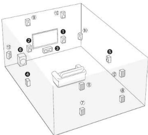
text_image
Isometric diagram of a living room layout with numbered furniture and objects, including a TV and sofa.To enjoy the Dolby Atmos listening mode, Height 1 speakers or surround back speakers need to be installed.
① ② Front speakers
3 Center speaker
4 5 Surround speakers
6 Subwoofer
⑦ ⑧ Surround back speakers
⑨ ⑩ Height 1 speakers (Front High)
Height 2 speakers (Rear High)
13 4 Wide speakers
• ⑪⑫ and ⑬⑭ share the same speaker terminals. Select either of the groups.
- To use the multi-zone function, see the section 5 "Using the multi-zone function" of "Step 3: Playing Back".
5.1 ch: Connect the speakers
①②③④⑤⑥ to the unit. ①② output front stereo sound. ③ outputs center sounds such as dialogs and vocals. ④⑤ create back sound field. ⑥ reproduces bass sounds and creates rich sound field. Up to four subwoofers can be connected to the unit.
Surround back speakers: Placing ⑦⑧ speakers allows playback in 7.1 ch configuration that improves sense of envelopment created by back sound field. It also improves seamlessness of back sounds and provides more natural sound experiences in the sound field.
Height speakers 1 and 2: Placing ⑨⑩ or ⑪⑫ speakers produce surround effects on a height plane.
• To enjoy the Dolby Atmos listening mode, Height 1 speakers or surround back speakers need to be installed.
- Although Height 1 speakers can enhance surround effects, we recommend you to add Height 2 speakers in order to ensure full effects.
• Install Height speakers such as Front High and Rear High speakers on the upper part of the front or rear wall. There are other types of Height speakers.
Wide speakers: Placing ⑬⑭ speakers makes the front sound field even wider. It also give smoother transitions between front and back surround sounds.
The power amplifier of this unit is designed for 9 ch configuration. Therefore, ⑦⑧ speakers cannot be used together with ⑩⑫ (or ⑬⑭ ) speakers during playback. When both groups are connected, you can switch speakers to be used on the Quick Setup menu that appears when you press Q Setup on the remote controller (Speaker Layout function).
- For details on the Speaker Layout function, see the section 4 "Using Quick Setup menu" of "Step 3: Playing Back".
- 11 ch playback is possible by connecting an external power amplifier to this unit. See the Advanced Manual for information on how to connect the external amplifier.
Height speakers arrangements (Dolby Atmos)
There are several types of Height speakers other than those mentioned in the previous section. See the next section "Combination patterns of Height speakers 1 and 2" and select the combination pattern from those specified for Height speakers 1 and Height speakers 2.
- This unit performs optimal sound field processing for the type of Height speakers 1 and 2 which is registered in initial settings (with setup wizard) according to an actual speaker layout. Note that the optimal effect cannot be achieved if you place Height speakers in a combination pattern other than those specified.
- Dolby recommends to place the speakers as described on "Installing speakers in ceiling" to obtain the best Dolby Atmos effect.
Step 1: Connections
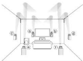
Using Dolby Enabled Speakers
natural_image
Interior layout diagram of a room with lighting fixtures and furniture (no text or symbols)③⑥ Dolby Enabled Speaker (Front)
c d Dolby Enabled Speaker (Surround)
⑤① Dolby Enabled Speaker (Back)
A Dolby Enabled Speaker is specially designed to be used as a Height speaker. There are two types of Dolby Enabled Speakers, the one is to be placed on the top board of other speakers such as front speakers and surround speakers, and the other is integrated type with the normal speakers. Dolby Enabled Speakers designed with their output facing toward the ceiling to create an elevated audio effect in the Dolby Atmos and Dolby Surround listening modes by providing sounds echoing off the ceiling.
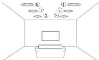
Installing speakers in ceiling
natural_image
Simple line drawing of a room interior with furniture and ceiling fixtures (no text or symbols)⑨ h Top Front
① ① Top Middle
④ Top Rear
Step 1: Connections
Ceiling speakers, etc. are used for maximizing effects in Dolby Atmos or Dolby Surround listening mode. Install Top Front speakers midway between the position just above the listening position and the position just above the front speakers. Install Top Middle speakers just above the listening position. Install Top Rear speakers midway between the position just above the listening position and the position just above the surround back speakers.
Combination patterns for Height speakers 1 and 2
Dolby recommends the following combination pattern to obtain the best effect of Dolby Atmos and Dolby Surround listening modes.
- Pair 1: Top Middle - Pair 2: Top Front / Top Rear
The following are the patterns of Height speakers 2 that can be selected according to the type of Height speakers 1.
Height speakers1: Front High
Height speakers 2: Not Use/Top Middle/Rear High/Dolby Enabled Speaker (Surround)/Dolby Enabled Speaker (Back)
Height speakers1: Top Front
Height speakers 2: Not Use/Top Rear
Height speakers1: Top Middle
Height speakers 2 cannot be used.
Height speakers1: Dolby Enabled Speaker (Front)
Height speakers 2: Not Use/Dolby Enabled Speaker (Surround)/Dolby Enabled Speaker (Back)
Height speakers1: Dolby Enabled Speaker (Surround)
Height speakers 2 cannot be used.
Height speakers1: Dolby Enabled Speaker (Back)
Height speakers 2 cannot be used.
- When front speakers are bi-amp connected, you can select a pattern for Height speakers 2 from the following options. Not Use/Front High/Top Front/Top Middle/Dolby Enabled Speaker (Front)/Dolby Enabled Speaker (Surround)/Dolby Enabled Speaker (Back)
flowchart
graph TD
    A["Surround R"] --> B["SURR"]
    B --> C["Height1 R"]
    C --> D["Height2 R/ Wide R"]
    D --> E["Front R"]
    E --> F["Front L"]
    F --> G["Height2 L/ Wide L"]
    G --> H["Height1 L"]
    H --> I["Center"]

    J["Surround back R"] --> K["BACK"]
    K --> L["R"]
    L --> M["FRONT"]
    M --> N["R"]
    N --> O["FRONT L"]
    O --> P["Back"]
    P --> Q["L"]
    Q --> R["Height2 L/ Wide L"]
    R --> S["/WIDE L"]
    S --> T["Height1 L"]
    T --> U["L"]

    V["Surround back L"] --> W["Back"]
    W --> X["L"]
    X --> Y["Height2"]
    Y --> Z["/WIDE L"]
    Z --> AA["Height1 L"]
    AA --> AB["L"]

    AC["Surround L"] --> AD["CENTER"]
    AD --> AE["/WIDE L"]
    AE --> AF["Height1 L"]
    AF --> AG["L"]

    style A fill:#f9f,stroke:#333
    style J fill:#f9f,stroke:#333
    style V fill:#f9f,stroke:#333
    style AC fill:#f9f,stroke:#333
    style AB fill:#f9f,stroke:#333
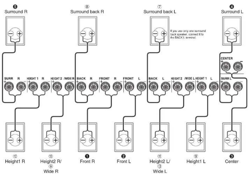
Instructions on how to connect speakers
Important: Connect speakers with 4 Ω to 16 Ω impedance. You have to change the setting if any of the speakers have 4 Ω or more to less than 6 Ω impedance. You can set up by viewing the guidance displayed on the TV screen. Press Receiver and then Home on the remote controller. Select "Setup" - "2.Speaker Setup" - "Speaker Settings" - "Speaker Impedance" and change the default value from "6ohms" to "4ohms".
- Select the item with the cursor buttons of the remote controller and press Enter to confirm your selection. To return to the previous screen, press Return.

Cut and remove the plastic coating from the end of the speaker cable, twist the core and connect it to the terminal. Make correct connection between the unit's jacks and speaker's jacks (+ to + and - to -) for each channel. If connection is wrong, a bass sound may become poor due to reverse phase. Attaching the supplied colored speaker cable labels to the + side on the both ends of each channel's cable will help correct connection.
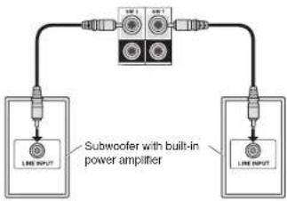
Connecting the Subwoofer
Up to four subwoofers with built-in power amplifier can be connected to the subwoofer jacks. Set the cut-off filter selection switch of the subwoofer to DIRECT. If the subwoofer does not have a cut-off filter selection switch but has a cut-off frequency adjusting dial, turn it to the maximum frequency.
flowchart
graph TD
    A["Subwoofer with built-in power amplifier"] --> B["Line INPUT"]
    A --> C["Line INPUT"]
    B --> D["Output"]
    C --> D
    style A fill:#f9f,stroke:#333
    style B fill:#ccf,stroke:#333
    style C fill:#ccf,stroke:#333
- The speaker setting is 7.2 ch at the time of purchase. You can change it manually or by using automatic speaker setting.
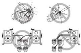
- Short-circuiting the + cable and - cable or contacting the cable core to the rear panel of the unit may cause failure. Also do not connect two or more cables to one speaker terminal or one speaker to several terminals.
• Using a speaker with less impedance than the setting may result in failure.
natural_image
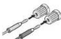
Four technical diagrams showing mechanical assembly or wiring connections without any text or symbolsWhen using commercially available banana plugs: tighten the speaker terminals to the end and then insert the banana plugs. Do not insert the cable core directly into the hole for banana plug of speaker terminal. (North American model)
3 Other connections
AM/FM Antenna Connections
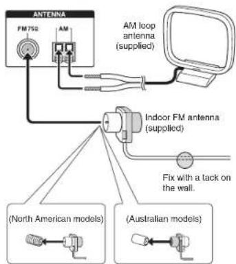
Connect the antennas to listen to AM/FM broadcast. When listening to the broadcast for the first time, adjust the antenna position and orientation to get the best reception.
text_image
ANTenna FM752 AM AM loop antenna (supplied) Indoor FM antenna (supplied) Fix with a lack on the wall. (North American models) (Australian models)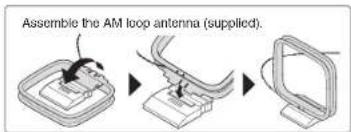
text_image
Assemble the AM loop antenna (supplied)Network Connection
You can enjoy Internet radio and DLNA by connecting the unit to LAN. The unit can be connected to the router with an Ethernet cable. Connect the Ethernet cable to the Ethernet port.
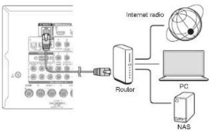
flowchart
graph TD
    A["Control Panel"] --> B["Router"]
    B --> C["Internet radio"]
    B --> D["PC"]
    B --> E["NAS"]
Headphones Connection
Connect stereo headphones with a standard plug (1/4 inch or 6.3 mm) to the PHONES jack on the front panel. Sound from the speakers will be off while you are using the headphones.
- If you selected any other listening mode than Stereo, Mono and Direct, connecting headphones will switch the listening mode to Stereo.
Step 2: Setting Up
Important: When the unit is turned on for the first time, the setup wizard of the section 2 will automatically be launched. If you use the setup wizard to make the initial setup, connect a TV to the HDMI OUT MAIN or SUB jack of the unit via HDMI connection.
1 Turning the power on
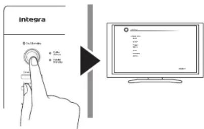
Connect the power cord to the outlet. Press ⓍOn/Standby on the main unit or ⓍReceiver on the remote controller to turn the unit on or to standby mode.
text_image
Integra 100% 200% 300%* This unit includes a removable power cord. Connect the power cord to AC INLET of the unit and then connect to the outlet. Always disconnect the outlet side first when disconnecting the power cord. When the unit is turned on, a large instantaneous current may flow affecting functionality of the computer and other devices. It is recommended to use a separate outlet from that for the computer or such other sensitive devices.
Firmware update notification: If the unit is connected via LAN and there is firmware update available, the "Firmware Update Available" message will appear. To execute updating, select "Update Now" with the cursor buttons of the remote controller and press Enter. When "Completed" appears, press ⏻On/Standby on the main unit to turn the unit into standby mode. Then updating will be completed.
- The unit automatically turns itself into standby mode 3 minutes after "Completed!" appears on the display. In this case also, updating will be completed.
2 Making the Initial Setup with the Setup Wizard
Read before starting the procedure: Set up by answering the guidance displayed on the TV screen. Select the item with the cursor buttons of the remote controller and press Enter to confirm your selection.
To return to the previous screen, press Return. - If you terminate the procedure on the way or change the setting made in the initial setup and want to call up the setup wizard again, press Receiver and then Home on the remote controller, select "Setup" - "7.Hardware Setup" - "Initial Setup", and press Enter.
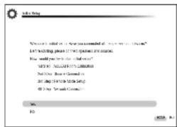
Select the language first. In the next screen, the summary of the setup wizard as below will be displayed. Select "Yes" in this screen and press Enter on the remote controller.
text_image
S is a key "What's not allowed to do you have been allowed to use the system" S is waiting, please check any waiting time. How would you wait before or after your computer? S is also allowed by your computer. This will be allowed to start your computer. Do you wait before your computer. Do you wait before your computer. OK F0 2024. 6.1The setup wizard proceeds in the four steps as below.
■ 1st Step : AccuEQ Room Calibration
■ 2nd Step : Source Connection
■ 3rd Step : Remote Mode Setup
■ 4th Step : Network Connection
■ 1st Step : AccuEQ Room Calibration
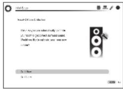
The test tone coming from each speaker will be measured to enable setting of the number of speakers, volume level, each speaker's optimum crossover frequencies, and distance from the primary listening position, and also enable correction of distortion caused by the room acoustic environment.
- You cannot return to the previous screen during speaker setup, even if you press Return.
- You cannot setup the wide speaker setting in the setup wizard. For details on setting up the wide speakers, see the Advanced Manual.
text_image
Ready 100% or 50% free How to you can't have already been of your phone. You can't have you been a phone? Do you like to make you now a phone? To < img> To < img>1. Place the speaker setup microphone.
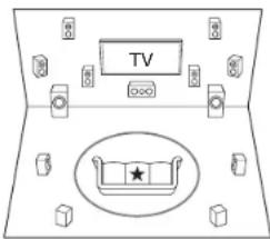
When the start screen above is displayed, before starting the procedure, place the supplied speaker setup microphone at the measurement position ★ by referring to the figure below.
text_image
TV○ : Listening area Measurement-position with microphone
* Correct measurement will not be possible if the microphone is held
by hand. Measurement is not possible if headphones are being used.
The subwoofer sound may not be detected since it is extremely low frequencies. Raise the subwoofer volume to around the half of its
maximum volume and make its frequency to the maximum level.
A loud test tone will be heard during measurement. Measurement may be interrupted if there is ambient noise or radio frequency interference. Close the window and turn off the home appliance and fluorescent light.
-
After placing the microphone at the measurement position, select "Do It Now" with the cursors and press Enter.
-
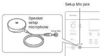
Connect the microphone to the Setup Mic jack of the unit.
text_image
Speaker setup microphone Setup Mic jack- Follow the guidance displayed on the TV screen.
text_image
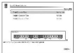
File Edit Options Format: Format Name: 100% Size: 50% Color: 100% Color Mode: Normal Color Value: 100% Color Color Index: 100% Color Color (Color) Index: 100% Color Color (Color) (Color) Index: 100% Color Color (Color) (Color) (Color) Index: 100% Color Color (Color) (Color) (Color) (Color) Index: 100%When the screen above is displayed, set the items with the cursors on the remote controller. Select the types for height 1/2 speakers if the height speakers are used. After front and height speakers types are selected, switch the screen using cursor ▼ to select the type of subwoofer. After setting the items, press Enter on the remote controller. Press Enter again in the next screen to start automatic speaker setting.
- Speaker terminals and settings description display at the bottom of the screen as you move the cursor to each item. Please refer to this information on the screen.
- The test tones sound from the connected speakers and automatic speaker setting starts.
Measurement will be made twice for each speaker. It takes several minutes to be completed. Keep the room as quiet as possible during measurement. If any of the speakers do not produce the test tone, check for disconnection.
- During measurement, each speaker outputs the test tones at a high volume. Be careful of sound leak that may disturb your neighbors, or be careful not to frighten young children.
- When the measurement is completed, the measurement result is displayed.
Press ◀/▶ on the remote controller to check the settings. Press Enter with "Save" selected. In the next screen showing that "AccuEQ Room Calibration" is "On", press Enter on the remote controller.
- If there is an error message, follow the on-screen instruction to remove the error cause.
About THX playback
THX recommends setting the speakers manually if you use THX-certified speakers or playing back with THX listening modes.
- THX recommends setting the crossover frequency to "80Hz(THX)" manually.
- Due to the electrical complexities and the interaction with the room, you may notice irregular results when setting the level or distance of each speaker. If this happens, THX recommends setting the speakers and the subwoofer manually.
- When "Please unplug setup microphone." Is displayed, disconnect the microphone.
■ 2nd Step : Source Connection
You can check whether or not each input source is connected correctly.
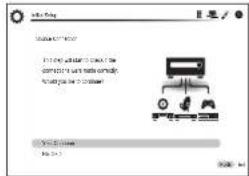
- When the Source Connection start screen is displayed, select "Yes, Continue" with the cursors and press Enter.
text_image
Sub-Play Wizard The installation is to check the computer's name and body code. The computer is to install a new file (12.0) You'll change My name to 7- Select the desired Input to check the connection and press Enter.
Start playback of the selected device. If connection is correct, video/audio of the input source selected on the unit will be played.
Step 2: Setting Up
- After checking the connection, select "Yes" with the cursors and press Enter.
- If you select "No" and press Enter, the error cause will be displayed. Follow the guidance to remove the error cause and check the connection again.
- Select "Yes" with the cursors and press Enter on the remote controller to check the connection of other inputs or select "No, Done Checking" and press Enter to skip.
If you select "Yes", you will return to the screen of step 2. If you select "No, Done Checking", you will proceed to step 5.
-
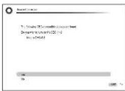
Enabling HDMI Linked Operation and Other Functions In the next screen, you can enable the HDMI linked operation with CEC compliant device, connection with ARC compatible TV, and HDMI Through function. Select "Yes" with the cursors to enable them or "No, Done Checking" to skip, and press Enter on the remote controller.
-
Select "Yes" with the cursors and press Enter to enable the CEC link function or select "No" and press Enter to keep it disabled.
text_image
Microsoft Windows This is not a successful completion program that is needed. Description: Microsoft Windows 2003 (1) Use as Default OK CancelIf you select "Yes", the connection with ARC compatible TV and HDMI Through function will be set to "Auto" and enabled.
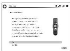
■ 3rd Step : Remote Mode Setup
text_image
OK Set SubIn this step, you can enable operation of the other components using the remote controller of the unit. When the Remote Mode Setup start screen is displayed, select "Yes" with the cursors and press Enter on the remote controller. Follow the guidance to select the desired Remote Mode button and in the keyboard screen, enter the first three characters of the brand name of the device you are going to program (e.g., "INT" for Integra) and search for the remote control code. The guidance will also explain how to set the remote controller.
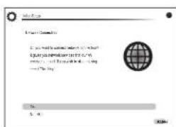
■ 4th Step : Network Connection
text_image
My Info I am your Service If you want to access your service, you should access your service to your service. You can access your service to your service. You can access your service to your service. You can access your service to your service. You can access your service to your service. You can access your service to your service. You can access your service to your service. You can access your service to your service. You can access your service to your service. You can access your service to your service. You can access your service to your service. You can access your service to your service. You can use the service to your service. You can use the service to your service. You can use the service to your service. You can use the service to your service. You can use the service to your service. You can use the service to your service. You can use the service to your service. You can use the service to your service. You can use the service to your service. You can use the service to your service. You can use the service to your service. You can use the services to your service. You can use the services to your service. You can use the services to your service. You can use the services to your service. You can use the services to your service. You can use the services to your service. You can use the services to your service. You can use the services to your service. You can use the services to your service. You can use the services to your service. You can use the services to your service. You can use the services for your service. You can use the services for your service. You can use the services for your service. You can use the services for your service. You can use the services for your service. You can use the services for your service. You can use the services for your service. You can use the services for your service. You can use the services for your service. You can use the services for your service. You can use the services for your service. You can use the services for you. You can use the services for you. You can use the services for you. You can use the services for you. You can use the services for you. You can use the services for you. You can use the services for you. You can use the services for you. You can use the services for you. You can use the services for you. You can use the services for you. You can use the services for you. You can use the services for you. You can be used in this system.You can check the network connection. When the Network Connection start screen is displayed, select "Yes" with the cursors and press Enter on the remote controller. If you select "Yes" in the next screen, you can view the Ethernet cable connection status.
Step 2: Setting Up
Step 3: Playing Back
1
Playing the player and TV

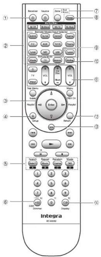
- To control the unit: The remote controller of this unit has the remote mode function for controlling other devices. You cannot control this unit when the remote controller is in the remote mode other than Receiver mode (for controlling this unit). Be sure to press ⑨ Receiver to select the Receiver mode before starting operation.
1. Turning the power on
Press ① ◎Receiver on the remote controller to turn the power on.
- Switch the input on the TV to that assigned to the unit. Use the TV's remote controller.
2. Select the input of the unit and start playback on the player or TV.
- Press② Input Selector to which the desired player has been assigned. Press TV/CD to play the TV's sound. You can also use the input selector buttons on the main unit.
- Input will automatically be selected if the TV or player is CEC compliant and connected to the unit with HDMI cable.
3. Select the desired listening mode.
Press ⑤ listening mode buttons to switch the mode so that you can enjoy different listening modes. For details about the listening modes, see "Listening modes" on the next section.
- Adjust the volume with ⑪.
text_image
Receiver Source Zone 1 Box Open Remote Mode/Input Selector Auto OK/OK MOS Game F.C. RUN V/CD Phang Tuner NE USB Control Mode TV Measure Multi TV VOL Ch Dis VOL Input Run Menu Menu Display Playful Enter Playful Setup Return Search Reset Random Mode Vocal Music Game OK 1 2 3 4 5 6 7 8 9 10 11 12 13 14 15 16 17 18 19 20 21 22 23 24 25 26 27 28 29 30 31 32 33 34 35 36 37 38 39 40 41 42 43 44 45 46 47 48 49 50 51 52 53 54 55 56 57 58 59 60 61 62 63 64 65 66 67 68 69 70 71 72 73 74 75 76 77 78 79 80 81 82 83 84 85 86 87 88 89 90 91 92 93 94 95 96 97 98 99 IntegraRemote Controller Parts Name
① ◎Receiver button: Turns the unit on or into standby mode.
② Remote Mode/Input Selector button: Switches the input to be played.
③ Cursor buttons and Enter button: Moves the cursor and confirms the selection.
④ Q Setup button: Displays the Quick Setup menu that allows you to set the frequently used functions including input selection and volume adjustment.
⑤ Listening mode buttons: Allows you to select the listening mode.
⑥ Dimmer button: Switches the brightness of the display.
⑦ Zone button: For use when the unit is connected with an integrated amplifier in a separate room and sound is played there.
⑧ Sleep button: Sets the time until the unit enters standby mode automatically.
⑨ Receiver button: Switches the remote controller to the mode for operating this unit.
⑩ Muting button: Temporarily mutes audio.
Volume buttons: Allows you to adjust the volume. This button also cancels the muting.
⑫ Return button: Returns the display to the previous state.
Home button: Displays the Home menu that allows you to make advanced settings and use Internet radio and DLNA.
⑭ Display button: Switches the information on the display.
- The buttons other than ① to ④ are for operating other devices.
Listening Modes
You can select a listening mode from various options such as Dolby Digital, Dolby Atmos and DTS. Select the desired mode by switching and listening actual sound in different modes. The selectable listening modes depend on the format of the input signals.
Movie/TV: You can select a listening mode suitable for movies and TV programs.
Music: You can select a listening mode suitable for music.
Game: You can select a listening mode suitable for games.
THX: You can select a THX listening mode.
- For details on the listening modes, see the Advanced Manual.
"Direct" for playing the input signals as-is Selecting this mode allows the input signals to be played as they are. For example, 2 ch signals of music CD will be played in stereo, 5.1 ch signals in 5.1 ch, and Dolby Digital signals of blu-ray disc or DVD in the Dolby Digital sound field according to the specified number of channels.
Other Useful Functions
■ Playing Video and Audio from Different Sources: It is possible to play audio and video from different sources. For example, you can play audio from the CD player and video from the BD/DVD player. In this case, press BD/DVD and then TV/CD. Then start playback on the BD/DVD player and CD player. This function is effective when an input with audio only has been selected (TV/CD, Tuner or Phono in the initial setting).
■ Adjusting Sound Quality: It is possible to enhance or moderate the low and high pitched ranges of front speakers. Press Tone on the main unit several times to select the desired setting from "Bass", "Treble", and "Phase Matching Bass" and adjust with +/-
- It cannot be set if the listening mode is Direct or THX. "Bass": Allows you to enhance or moderate the low pitched range.
"Treble": Allows you to enhance or moderate the high pitched range.
"Phase Matching Bass": Allows you to keep the clear midrange and effectively enhance the low pitched range.
■ Muting Temporarily: Press Muting on the remote controller. To cancel the muting, press Muting again, or press VOL ▲/▼.
■ Changing the Display Brightness: Press Dimmer on the remote controller. The display brightness changes each time you press the button.
- Checking the Input Format: Press Display on the remote controller several times to switch the display of the main unit in order of:
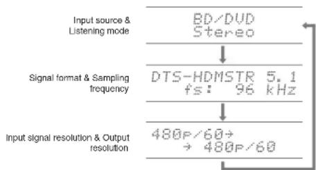
flowchart
graph TD
    A["Input source & Listening mode"] --> B["BD/DVD Stereo"]
    B --> C["Signal format & Sampling frequency"]
    C --> D["DTS-HDMSTR 5.1 fs: 96 kHz"]
    D --> E["Input signal resolution & Output resolution"]
    E --> F["480P/60 → 480P/60"]
- If "Dolby D 5.1" is displayed in signal format, the Dolby Digital 5.1 ch signals are being input. When listening to AM/FM radio, the band, frequency and preset number are displayed.
Step 3: Playing Back

Listening to AM/FM Radio
The Basic Manual explains the method using automatic tuning. For manual tuning, see the Advanced Manual.
- Press Tuner on the main unit several times to select either "AM" or "FM".
- Press Tuning Mode on the unit, so that the "AUTO" indicator on the display lights.
- Press Tuning ▲ the unit.
The automatic tuning to a radio station starts. Searching stops when one is tuned. When tuned into a radio station, the "▶TUNED indicator on the display lights. The "FM STEREO" indicator lights if the radio station is an FM radio station.
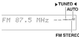
text_image
TUNED AUTO FM 87.5 MHz FM STEREO(Actual display depends on the country.)
Registering an AM/FM Radio Station
It allows you to register up to 40 of your favorite AM/FM radio stations.
- Tune into the AM/FM radio station you want to register.
- Press Memory on the unit. The preset number on the display flashes.
- Repeatedly press Preset ◀▶ on the unit to select a number between 1 and 40 while the preset number is flashing (about 8 seconds).
- Press Memory on the unit again. When registered, the preset number stops flashing. To select a preset radio station, press Preset◀▶ on the main unit or CH +/- on the remote controller.

Using the Home menu
In the Home menu, you can make advanced setup and use Internet radio and DLNA function. For details on the operation, see the Advanced Manual.
1. After pressing Receiver, press Home on the remote controller.
The Home menu is displayed on the TV screen. You can also use the Home button on the main unit.
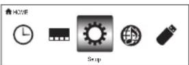
2. Select the item with the cursor buttons of the remote controller and press Enter to confirm your selection. To return to the previous screen, press Return. To return to the Home menu, press Home.
■ Sleep Timer: Select to turn the unit into standby mode automatically when the specified time elapses.
■ InstaPrevue: Select to preview videos input from the HDMI input jacks collectively in a single screen. The screen has a main window (current input video) and sub windows (other input videos). To switch the current input, select the desired sub window with the cursor buttons and press Enter.
- A black sub window is shown for the input with no video signals.
- "InstaPrevue" cannot be selected if the video is being input from HDMI IN 5, 6 or 7 or if there is no signal from the input currently selected.
- "InstaPrevue" cannot be selected if "Zone 2 Monitor Out" is set to "Use" and Zone 2 is on.
- Depending on video signals, the picture may not be properly rendered on the preview thumbnails.
■ Setup: You can change the assignment of input terminals and input selector buttons and also make various speaker settings and other advanced settings.
■ Network Service: Select to use Internet radio services and the DLNA function. When you connect the unit to the network and press Enter, the network service screen will be displayed on the TV. On the TV screen, select the desired service or music file with the cursors of the remote controller and press Enter to confirm and start playback.
Internet radio service: You can listen to TuneIn or such other Internet radio stations registered in advance.
DLNA : You can play music files stored in the PC or NAS device connected to the network. Select the server with the cursors, select the desired music file and press Enter to start playback.
Home Media: You can play music files in a shared folder on the PC or NAS device connected to the network. Select the server with the cursors, select the desired music file and press Enter to start playback.
- "Network Service" becomes selectable after the network starts up even if it cannot be selected first. It may take about a minute to start up.
- When "Network Service" is selected for the first time, the "DISCLAIMER" screen will appear on the TV. Select "Agree" if you agree the content. If you do not agree the content, you cannot use the network service.
* You cannot use the function unless the TV is connected via HDMI since selecting "Agree" in the "DISCLAIMER" screen is not possible - Layout of the icons in the "Network Service" top menu can be changed. Press NET on the remote controller and press D. Select the source icon with the cursors and press Enter, and then select the destination icon and press Enter. The positions of the icons are switched each other.
■ USB: Select "USB" in the TV screen and connect a USB storage device to the USB port on the front panel. On the TV screen, select the desired folder or music file with the cursors of the remote controller and press Enter to confirm and start playback.
- "USB" becomes selectable after the USB function starts up even if it cannot be selected first. It may take about a minute to start up.
Step 3: Playing Back

Using Quick Setup menu
In the Quick Setup menu, you can set frequently used functions including input selection and volume adjustment.
1. Press Q Setup on the remote controller.
The Quick Setup menu is displayed on the connected TV's screen.
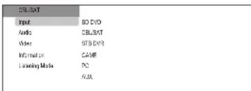
text_image
CBL/SAT Input BO DVD Audio CBL/SAT Video STB DVD Information CAME Listening Media PC AVA2. Select the item with the cursor buttons of the remote controller and press Enter to confirm your selection.
• To return to the previous screen, press Return.
■ Input: Select the input and check the assignment of input selector buttons.
■ Audio: You can perform various audio settings including audio quality and speaker level adjustment.
- You cannot select this item when audio is output from the TV's speakers.
A/V Sync: If the video is behind the audio, you can delay the audio to offset the gap. Different settings can be set for each input.
- It cannot be set if the input is "NET" or "USB".
• It cannot be set if the listening mode is Direct.
Bass, Treble: Adjust volume of the front speaker.
• It cannot be set if the listening mode is Direct or THX.
Phase Matching Bass: Suppress phase shift in the midrange to enhance bass sound. Thus smooth and powerful bass sound can be obtained.
• It cannot be set if the listening mode is Direct or THX.
Subwoofer 1/2 Level, Center Level: Adjust the speaker level while listening to the sound. The adjustment you made will be reset to the previous status when you turn the unit to standby mode.
- The speakers cannot be adjusted if they have been set to "No" or "None" in "Speaker Configuration".
- "Subwoofer 2 Level" cannot be adjusted if "Subwoofer" have been set to "1ch" in "Speaker Configuration".
AccuEQ Room Calibration: Disable the sound field set in the automatic speaker setting. The setting can be separately set to each input.
- This setting cannot be selected if the automatic speaker setting has not been performed.
- It cannot be set if headphones are connected or the listening mode is Direct.
Late Night: Make small sounds to be easily heard. It is useful when you need to reduce the volume while watching a movie late night. You can enjoy the effect on Dolby Digital and Dolby Digital Plus only.
- Turning the unit to standby mode will set the setting to "Off".
- This function cannot be used if "Loudness Management" is set to "Off".
Music Optimizer: Improve the quality of the compressed audio. Playback sound of lossy compressed files such as MP3 will be improved. The setting can be separately set to each input.
• The setting is effective in the signals of 48 kHz or less.
The setting is not effective in the bitstream signals.
• It cannot be set if the listening mode is Direct.
Re-EQ, Re-EQ (THX): Adjust the soundtrack that was processed to enhance its high pitch range, in order to make it suitable for home theater.
- In Re-EQ, the following listening modes can be used: Dolby Digital, Dolby Digital Plus, Dolby TrueHD, Multichannel, DTS, DTS-HD High Resolution Audio, DTS-HD Master Audio, DTS Express, DSD, and DTS Neo:X Cinema.
- In Re-EQ (THX), the following listening modes can be used: THX Cinema, THX Surround EX, and THX Select2 Cinema.
Screen Centered Dialog: Height speakers are used to move acoustic images such as dialogs from the center speakers upward according to the height of the TV screen. Acoustic images of the center speakers move up as the set value is increased.
- This item may not be available depending on the selected listening mode.
• This function cannot be used if headphones are connected. - This function cannot be used if "Height 1 Speakers Type" is not set to "Front High".
Speaker Layout: You can give priority to surround back speakers, height 1/2 speakers or wide speakers when they are all connected.
Back+Height 1: Audio outputs from surround back speakers and Height 1 speakers are given priority. Back+Wide: Audio outputs from surround back speakers and wide speakers are given priority. Height 1+2: Audio outputs from Height 1 speakers and Height 2 speakers are given priority.
"Back" and "Height 1": Displayed when Zone 2 playback is performed via Height 2/ wide speaker terminals (ZONE 2 terminals) while surround back and Height 1 speakers are connected. "Back" means that audio outputs from surround back speakers are given priority.
"Height 1" means that audio outputs from Height 1 speakers are given priority.
"Back" and "Wide": Displayed when speakers are bi-amp connected, passive subwoofer is connected, or Zone 3 playback is performed via Height 1 speaker terminals (ZONE 3/Bi-AMP terminals) while surround back and wide speakers are connected. "Back" means that audio outputs from surround back speakers are given priority. "Wide" means that audio outputs from wide speakers are given priority.
"Back" and "Height 2": Displayed when speakers are bi-amp connected, passive subwoofer is connected, or Zone 3 playback is performed via Height 1 speaker terminals (ZONE 3/ Bi-AMP terminals) while surround back and Height 2 speakers are connected. "Back" means that audio outputs from surround back speakers are given priority. "Height 2" means that audio outputs from Height 2 speakers are given priority.
- Selectable items vary depending on the playing conditions such as input source, speaker configuration etc.
- The speakers cannot be selected if they have been set to "None" in "Speaker Configuration".
- This function cannot be used if "11ch Playback" is set to "Yes".
- This function cannot be used in the listening mode which does not use surround back speakers, height 1/2 speakers or wide speakers.
- This function may not be effective depending on the selected listening mode or input source.
Video:
Monitor Out: The video input signals input to the unit will be converted by the unit when they are output from the HDMI OUT jack to the TV so that their resolution can match that of the TV used. Select the HDMI OUT jack to be used for output.
Control Monitor: Select the main room TV or the separate room TV for which the CEC link function is enabled when HDMI connection between the unit and the separate room TV is established by Zone function. For details on Zone function, see the next section "Using the multi-zone function".
Wide Mode: You can set the aspect ratio.
Picture Mode: You can adjust the image quality. "Cinema" will automatically adjust the image to be suitable to watch movie and "Game" suitable to play game. In "Standard", the resolution will be changed but the image quality will not be adjusted. In "Custom", "ISF Day" and "ISF Night", you can adjust the brightness, contrast, hue and saturation as desired. If you do not adjust the resolution and image quality, select "Bypass".
• "Video" cannot be selected if the input is "NET" or "USB".
Information:
Audio: Displays the audio input source, format, number of channels, sampling frequency, listening mode, number of output channels, and other audio information.
Video: Displays the video input source, resolution, signal format, color tone, 3D information, Aspect, Picture Mode, output, and other Video information.
Tuner: Displays the band, frequency, preset number, and other tuner (radio) information.
■ Listening Mode: Select the listening mode from the categories of "Movie/TV", "Music", "Game" and "THX". - It cannot be set when audio is played from the TV's speakers.
5
Using the multi-zone function
The function allows you to connect the unit with a TV or audio equipment placed in a separate room so that you can enjoy audio and video of the connected equipment even if you are staying in a different room. It is possible to perform playback in the main room and a separate room at the same time, for example by playing the Blu-ray Disc player in the main room where the unit is placed while playing Internet radio in a separate room. It is also possible to perform playback only in a separate room. There are four methods to configure multi-zone connection as described in "a" to "d" in the right. Simultaneous playback in all zones is also possible.
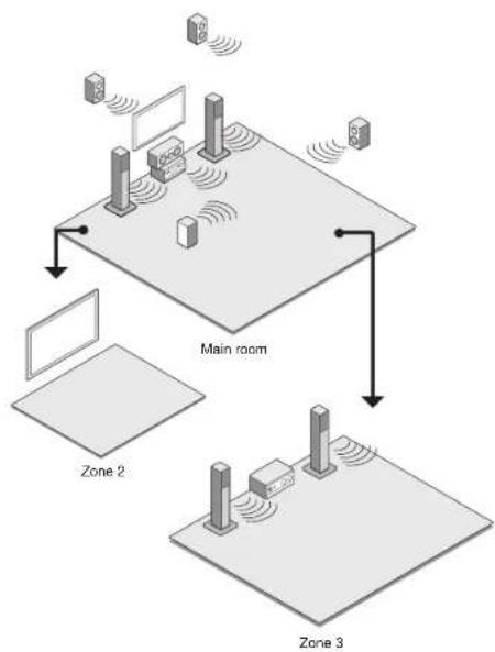
flowchart
graph TD
    A["Main room"] --> B["Zone 2"]
    A --> C["Zone 3"]
    B --> D["Device 1"]
    B --> E["Device 2"]
    C --> F["Device 3"]
    C --> G["Device 4"]
    D --> H["Monitor"]
    E --> I["Monitor"]
    F --> J["Monitor"]
    G --> K["Monitor"]
    style A fill:#f9f,stroke:#333
    style B fill:#ccf,stroke:#333
    style C fill:#ccf,stroke:#333
    style D fill:#cfc,stroke:#333
    style E fill:#cfc,stroke:#333
    style F fill:#cfc,stroke:#333
    style G fill:#cfc,stroke:#333
    style H fill:#fcc,stroke:#333
    style I fill:#fcc,stroke:#333
    style J fill:#fcc,stroke:#333
    style K fill:#fcc,stroke:#333
- The sources from which you can enjoy the sound in a separate room: For Zone 2, any can be selected from among an external device connected to the HDMI input jacks or the analog audio input jacks (×) of the unit, the "NET" or "USB" source, and the AM/FM broadcasting. For Zone 3, any can be selected from among an external device
connected to the analog audio input jacks (*) of the unit, the "NET" or "USB" source, and the AM/FM broadcasting. When you connect a CD player or such other player without HDMI output jack, connect it to the analog audio input jacks of the unit. Multi-zone output is not possible if the connection is only with digital optical cable or digital coaxial cable. In case of analog connection, analog audio output setting may be necessary on the player.
- As for HDMI input and analog audio input, it is possible to play the same source or different sources in the main room and separate room.
- As for the "NET" and "USB", you cannot select different audio sources for the main room and separate room. For example, if "NET" has been selected in the main room and then "USB" is selected as playback source in the separate room, the input in the main room will change to "USB" accordingly.
- When listening to AM/FM broadcasting, you cannot select different stations for the main room and separate room. Therefore broadcasting of the same station will be heard in the both rooms.
- If you play the same HDMI connected player for the main room and a separate room, the sound field processing for 2 ch PCM signals will be made in the main room.
Outputting Video/Audio to a Separate Room
■ a. Connecting a TV in a separate room using HDMI cable
You can play video and audio of the HDMI connected player on the TV in a separate room. With an HDMI cable, connect between the HDMI OUT ZONE 2 jack of the unit and the HDMI IN jack of the TV in a separate room.
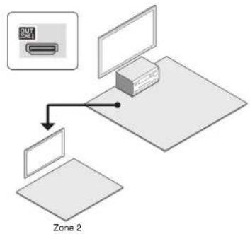
flowchart
graph TD
    A["Device"] --> B["Zone 2"]
    C["Computer"] --> B
    D["OLT ONE1"] --> A
Step 3: Playing Back
Change the setting: Press Receiver and then Home on the remote controller, select "Setup" - *1.Input/Output Assign" - "Monitor Out" - "Zone 2 Monitor Out" and set the setting to "Use".
• You can view the information of the connected device on the TV of Zone 2 by pressing Display during Zone 2 playback.
■ b. Connecting a TV in a separate room using composite video cable
Video from the player without HDMI out jack can be displayed on the TV in a separate room. First, connect the player to composite video input jack of the unit. Then, connect the TV in the separate room to ZONE 2 OUT V jack of the unit using a composite video cable.
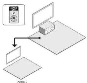
flowchart
graph TD
    A["TV Tension Sensor"] --> B["Box"]
    C["Panel 1"] --> D["Panel 2"]
- It is not possible to output video from the player to the TV in the separate room if the player is connected to the HDMI IN jack or COMPONENT VIDEO IN jack.
- In this connection method, audio from the player cannot be output from the TV. To output audio in the separate room, see the next section "Listening to Music in a Separate Room" and connect the unit to the integrated amplifier or speakers located in the room where the TV is placed.
Listening to Music in a Separate Room
■ c. Connecting an Integrated Amplifier in a Separate Room
It is possible to play 2 ch source in a separate room while 9.2 ch source is being played in the main room. Connect the PRE/LINE OUT ZONE 2 jacks or PRE/LINE OUT ZONE 3 jacks of the unit and the line-in jacks of the pre-main amplifier in a separate room with an analog audio (RCA) cable.
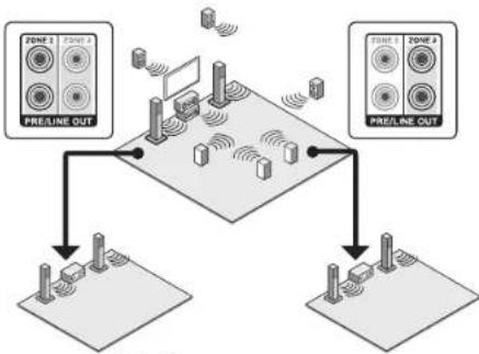
flowchart
graph TD
    A["PRELINE OUT"] --> B["Central Device"]
    C["PRELINE OUT"] --> B
    D["Input/Output Devices"] --> B
    style A fill:#f9f,stroke:#333
    style C fill:#f9f,stroke:#333
    style D fill:#ccf,stroke:#333
Zone 2 Zone 3
- Volume can be adjusted with both the unit and the pre-main amplifier used in a separate room. To adjust it with the unit, press Receiver and then Home on the remote controller, select "Setup" - "7. Hardware Setup" - "Multi Zone" - "Zone 2 Out" or "Zone 3 Out" and set the setting to "Variable". If you connect a power amplifier, be sure to make the setting and adjust the volume in the main room.
■ d. Connecting Speakers in a Separate Room
It is possible to directly connect the speakers in another room without an amplifier. Connect the speakers in the separate room to ZONE2 or ZONE3 speaker terminals of the unit using speaker cables. Note that 7.2 ch will be the maximum in the main room during Zone 2 or Zone 3 playback. When both Zone 2 and Zone 3 playbacks are performed at the same time, 5.2 ch will be the maximum in the main room.
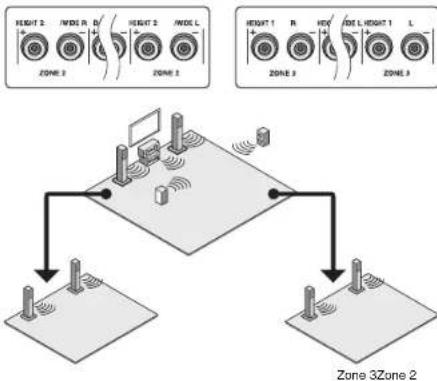
flowchart
graph TD
    subgraph_Zone_1["Zone 1"]
        A1["HEIGHT 2"] --> B1["IN/IDE R"]
        B1 --> C1["D"]
        C1 --> D1["HEIGHT 2"] --> E1["IN/IDE L"]
        E1 --> F1["ZONE 3"]
        G1["ZONE 3"] --> H1["HEIGHT 1"] --> I1["IN/IDE R"]
        I1 --> J1["HIV"]
        J1 --> K1["SIZE L"] --> L1["HEIGHT 1"] --> M1["L"]
        M1 --> N1["ZONE 3"]
    end
    subgraph_Zone_2["Zone 2"]
        O1["Height Indicator"] --> P1["Device Array"]
        P1 --> Q1["Sensor Platform"]
        Q1 --> R1["Device Array"]
        R1 --> S1["Sensor Platform"]
        S1 --> T1["Device Array"]
        T1 --> U1["Sensor Platform"]
        U1 --> V1["Device Array"]
        V1 --> W1["Sensor Platform"]
        W1 --> X1["Device Array"]
        X1 --> Y1["Sensor Platform"]
    end
Required setting: Press Receiver and then Home on the remote controller. Select "Setup" - "2. Speaker Setup" - "Speaker Settings" and set "Powered Zone 2" or "Powered Zone 3" to "Yes".
• Volume adjustment can be performed only from the unit.
Performing Multi-zone Playback
- Press ZONE on the remote controller a repeatedly to select Zone 2 or Zone 3. Point the remote controller at the unit and press ⏻Receiver.
"Z2" or "Z3" lights on the main unit display and Zone function is enabled.
- The Zone button stays lit red when Zone 2 is selected and green when Zone 3 is selected.
- Press Input Selector of the input source to be played in a separate room.
If you turn the unit to standby during multi-zone playback, the Z2/Z3 indicators are dimmed and the playback mode is switched to playback in a separate room only. Performing steps 1 and 2 while the unit is in standby also switches the playback mode to playback in a separate room only.
Step 3: Playing Back
To control on the main unit: Press Zone2 or Zone3 and within 8 seconds, press the input selector button of the input to be played in a separate room. To play the same source in the main room and separate room, press Zone2 or Zone3 twice.
To turn off the multi-zone function: Press Zone on the remote controller repeatedly to select Zone 2 or Zone 3. Press ☐Receiver. To control on the main unit, press Zone2 or Zone3 and within 8 seconds, press Off.
To adjust the volume: Press Zone on the remote controller a repeatedly to select Zone 2 or Zone 3. Adjust the volume using VOL ▲/▼. To do this on the main unit, press Zone2 or Zone3, and adjust the volume using the Master Volume control within 8 seconds.
To temporally mute the audio: Press Zone on the remote controller repeatedly to select Zone 2 or Zone 3. Then, press Muting to mute the audio.
To adjust the sound quality for the separate room: Press Zone2 on the main unit. Press Tone a few times to display "Bass", "Treble" or "Balance" on the display. When the desired item appears on the display, adjust the value with + or - button.
- If "Zone 2 Out" is set to "Fixed", sound quality adjustment are not effective.
- If Zone 2 or Zone 3 is on, power consumption during standby becomes larger than normal.
- While Zone 2 or Zone 3 is on, the RI linked system function (interlink between Onkyo components) is disabled.
WHOLE HOUSE MODE: If you press Whole House Mode while playback is being performed in the main room, the WHOLE HOUSE MODE is turned on, 'Z2' and 'Z3' on the display light at the same time and the playback sources of all the rooms are switched to the same source at once.
- WHOLE HOUSE MODE is effective only for playback of the external player connected to the analog audio input jacks.
- This function cannot be used if headphones are connected or audio is output from the speakers of the TV.
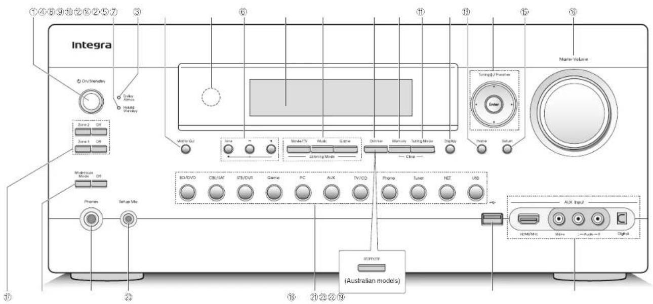
text_image
Integra On/Stanley Delay Audio Hindall Stanley Zone 2 ON Zone 1 ON Master Mode ON Phono Setup Mix ID/DVD ON/SAT ST/DVS Game FC AUX TV/CD Phone Tuner NET USB Tuning / Parallel Enter Mode Reset Power/VP (Australian models) ACX Input HDMI/UL Mio -Audio-0 DigitalFront Panel
① On/Standby button: Turns the unit on or into standby mode.
② Hybrid Standby indicator: Lights if the unit enters standby mode when the HDMI Through or network standby is enabled.
③ Dolby Atmos indicator: Stays lit when the Dolby Atmos listening mode is selected with Height speakers or surround back speakers enabled.
④ Monitor Out button: Allows you to select the HDMI jack to output the video input signals that are input to the unit.
⑤ Remote control sensor: Receives signals from the remote controller.
⑥ Tone and Tone Level buttons Adjusts the high tone and low tone.
⑦ Display
⑧ Listening Mode buttons: Allows you to select the listening mode.
⑨ Dimmer button (North American model): Switches the brightness of the display.
RT/PTY/TP button (Australian model): Can be used when receiving the station transmitting text information.
⑩ Memory button: Registers or deletes a station.
⑪ Tuning Mode button: Switches the tuning mode.
⑫ Display button: Switches the information on the display.
⑬ Home button: Displays the Home menu.
④ Cursor buttons, Tuning▼ button, Preset◀▶ button and Enter button: Moves the cursor and confirms the selection. When listening to AM/FM broadcasting, tune into the station with Tuning▼ or select the registered station with Preset◀▶.
⑮ Return button: Returns the display to the previous state.
⑯ Master Volume: Allows you to adjust the volume.
⑰ Zone 2 button. Zone 3 button and Off button:
Controls the multi-zone function.
⑯ Whole House Mode button: Controls the WHOLE HOUSE MODE function to play the same source in all the multi-zone connected rooms.
⑲ Phones Jack: Stereo headphones with a standard plug are connected.
⑳ Setup Mic jack: The supplied speaker setup microphone is connected.
② Input selector buttons: Switches the input to be played.
USB port: A USB storage device is connected so that music files stored in it can be played.
AUX Input HDMI/MHL Jacks: An HD video camera or MHL-enabled mobile device is connected. It is possible to send video and audio of an MHL-enabled mobile device.
AUX Input AUDIO/VIDEO, DIGITAL Jacks: A video camera or such other device is connected.
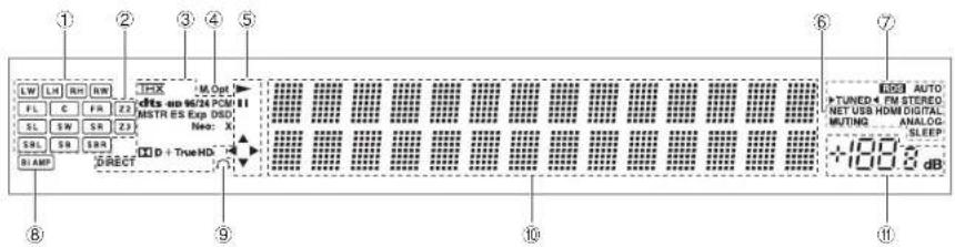
text_image
① ② ③ ④ ⑤ ⑥ ⑦ LW LH RS RW FL C FR ZS SL SW SR ZS SB SB SBR BIAMP DIRECT M Opt dcts on 96/24 PCM II MSTR ES Exp SSD: Neo: X D + TrueHD ⑧ ⑨ ⑩ ⑪ LED AUTO TUNED + FM STEREO NET USB HDMI DIGITAL RUTING ANALOG SLEEP +100.8 dBDisplay
① Speaker/Channel display: Displays the output channel that corresponds to the selected listening mode.
② Z2/Z3: Lights when the output to Zone 2/Zone 3 is set to on.
③ Lights according to the type of input digital signals and the listening mode.
④ Stays lit when Music Optimizer is enabled.
⑤ Lights when NET or USB is controlled.
⑥ NET: Stays lit when the "NET" input is selected and the unit is connected to the home network (LAN). It will flash if the connection is not correct.
USB: Stays lit when the "USB" input is selected and a USB storage device (e.g. USB memory) is connected. It will flash if the connection is not correct. HDMI: Stays lit when HDMI signals are input and the HDMI input is selected.
DIGITAL: Stays lit when digital signals are input and the digital input is selected.
MUTING: Flashes when Muting on the remote controller is pressed and audio is temporarily muted.
ANALOG: Stays lit when analog signals are input and the analog input is selected. Or, it stays lit when HDMI and digital signal inputs are not assigned.
SLEEP: Stays lit when the sleep timer is set.
⑦ Tuning indicators
RDS (Australian model): Stays lit when RDS broadcasting is being received.
AUTO: Stays lit when the tuning mode is auto.
TUNED: ▶◀ flashes while tuning is automatically performed. When tuned into a radio station, the
"▶TUNED◀" on the display lights.
FM STEREO: Stays lit when an FM broadcasting is being received.
⑧ Bi AMP: Stays lit when "Front Speakers Type" is set to "Bi-Amp".
⑨ Stays lit when headphones are connected.
⑩ Displays various information of the input signals. Pressing Display displays the type of input digital signals and the listening mode.
⑪ Displays the volume level.
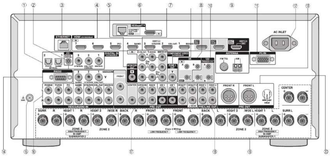
text_image
① ② ③ ④ ⑤ ⑥ ⑦ ⑧ ⑨ ⑩ ⑪ ⑫ AC INLET HOTBET® ETHERNET HDMI (HYDROOD) CN1 7 6 5 PCI 4 NAME 3 CONTROL 2 CONTROL 1 CONTROL INTU 2.0VAC 1.0VAC MINI COMPONENT VIDEO CONTROL IN V A B A FRIGER OUT ANTENNA FM TID AM PG IN R123 1 2 1 MONITOR V PHONE TVCD PC GAME ST/DOVR CBS/SAT SD/DVD R VIDEO/AUDIO IN PRE OUT PRE/LINE OUT PRE OUT SURR R HEIGHT 1 R HEIGHT 2 /WIDE R BACK R FRONT R FRONT L BACK L HEIGHT 2 /WIDE L HEIGHT 1 L SURR L + + + + + + ZONE 3 HIGH FREQUENCY B-AMP SUBWOPOR 3 ZONE 2 Class 3 Wiring LOW FREQUENCY LOW FREQUENCY ZONE 3 HIGH FREQUENCY B-AMP SUBWOPOR 1Rear Panel
① DIGITAL IN COAXIAL/OPTICAL jacks: Digital audio signals are input.
② RI REMOTE CONTROL jack: An Onkyo product with RI jack can be connected and synchronized with this unit.
③ ETHERNET port: Used for LAN connection
④ HDMI IN/OUT jacks: Digital video signals and audio signals are transmitted between the unit and the connected devices.
⑤ MONITOR OUT V Jack: Video signals are output to the connected monitor or TV.
⑥ HDBaseT™ IN / OUT ports: HDMI input signals are output via the Ethernet cable. As they are covered with a seal when shipped, remove it when you use the ports. Do not use the ports to connect the Ethernet port of network device.
⑦ COMPONENT VIDEO IN and OUT jacks: Component video input/output jacks.
⑧ ZONE 2 OUT V Jack: Video signals of the player are output to the connected TV in the separate room.
⑨ IR IN A/B, IR OUT Jacks (*): Connected to the multiroom remote control kit.
10 12V TRIGGER OUT A/B/C jack (*): Allows you to connect a device with trigger input jack in a separate room to enable power link operation between the device and the unit.
⑪ PC IN Jack: PC is connected via an analog RGB cable.
⑫ AC INLET: The power cord is connected.
⑬ FM ANTENNA jack (75 Ω) and AM ANTENNA terminal: The supplied antennas are connected.
⑭ RS232 port (*): Connected to the home control system.
⑮ GND terminal: The ground wire of the turntable is connected.
⑯ Composite video and analog audio jacks: Analog video signals and audio signals are input.
⑰ PRE OUT jacks: A power amplifier or subwoofer with built-in amplifier is connected.
⑯ PRE/LINE OUT ZONE 2/ZONE 3 jacks: Audio output jacks connected to the pre-main amplifier for multi-zone playback in a separate room.
⑲ SPEAKERS terminals: Speakers are connected. To use the Multi-zone function, connect the speakers in the separate room to the ZONE2 speaker terminals.
20 PRE OUT BALANCE Jacks: An amplifier with balance-type XLR input jacks is connected.
* Special devices or cable connections are necessary to use the control functions (9, 12) and (34). Contact the specialized stores for more information.
Troubleshooting
Before starting the procedure
Problems may be solved by simply turning the power on/off or disconnecting/connecting the power cord, which is easier than working on the connection, setting and operating procedure. Try the simple measures on both the unit and the connected device. If the problem is that the video or audio is not output or the HDMI linked operation does not work, disconnecting/connecting the HDMI cable may solve it. When reconnecting, be careful not to wind the HDMI cable since if wound the HDMI cable may not fit well. After reconnecting, turn off and on the unit and the connected device.
The AV receiver turns off unexpectedly.
- The AV receiver will automatically enter standby mode when Auto Standby is set and launched.
There's no sound, or it's very quiet.
- A wrong input selector button has been selected. Select a correct input for the player. Also check that muting is not on.
• Not all listening modes use all speakers.
There's no picture.
- A wrong input selector button has been selected.
- To display video from the connected player on the TV screen while the unit is in standby, you need to enable HDMI Through function.
- When the TV image is blurry or unclear, power cord or connection cables of the unit may have interfered. In that case, keep distance between TV antenna cable and cables of the unit.
- If you connect a player supporting HDCP2.2, be sure to connect it to the HDMI IN3 jack of the unit. At the time, connect the TV to the HDMI OUT MAIN jack.
HDMI control does not function correctly.
- Set the CEC link function of the unit to on. It is also necessary to make the HDMI linked system setting on the TV. See the TV's instruction manual for details.
The remote controller does not work.
- Be sure to press Receiver first before operating the unit with the remote controller.
There is no sound for multi-zone function.
- When you connect a CD player or such other player without HDMI output jack, connect it to the analog audio input jacks of the unit. Multi-zone output is not possible if the connection is only with digital optical cable or digital coaxial cable. In case of analog connection, analog audio output setting may be necessary on the player.
Cannot access to network.
- Try plugging/unplugging the unit or the router or check their power-on status. This will work well in many cases.
■ Resetting the unit
Resetting the unit to the status at the time of shipment may solve the problem. If the measures above do not solve the problem, reset the unit with the following procedure. If you reset the unit status, your preferences will be reset to the defaults. Note them down before starting reset.
- How to reset:
- While holding down CBL/SAT on the main unit (note that step 2 must be performed with this button pressed down)
- Press ⏻On/Standby on the main unit ("Clear" appears on the display and the unit returns to standby)
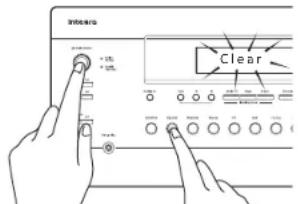
- Press On/Standby.
- While holding down CBL/SAT,
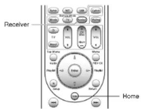
● How to reset the remote controller:
- While holding down Receiver on the remote controller, press Home (about 3 seconds) until Receiver lights.
- Within 30 seconds, press Receiver again.
text_image
Receiver TV VOL VOL Top Home Home Back Power Power Back HomeSpecifications
Amplifier Section
Rated Output Power
All channels: 135 watts minimum continuous power per channel, 8 ohm loads, 2 channels driven from 20 Hz to 20 kHz, with a maximum total harmonic distortion of 0.08% (FTC)
(North American)
9 ch × 185 W at 6 ohms, 1 kHz, 1 ch driven of 1% (IEC) (Others)
Maximum Effective Output Power
9 cm x 250 W Dynamic Power (k)
250 W (4 Ω, Front) 150 W (B O, Front)
THD+N (Total Harmonic Distortion+Noise)
0.08% (20 Hz - 20 kHz, half power)
Damping Factor
60 (Front, 1 kHz, 8 Ω)
Input Sensitivity and Impedance (Unbalance)
200 MV/47 RΩ (LINE)
2.5 mV/47 kΩ (PHONO MM)
Rated RCA Output Level and Impedance
200 mV/470 Ω (PRE OUT)
Maximum RCA Output Level and Impedance
4.6 V/470 Ω (PRE OUT)
Rated XLH Output Level and Impedance
400 mV/470 Ω (PRE OUT)
Maximum XLH Output Level and Impedance
9.2 V/470 Ω (PRE OUT)
Phono Overload
70 mV (MM 1 kHz 0.5% Direct)
Frequency Response
5 Hz - 100 kHz/+1 dB, -3 dB (Direct mode)
Tone Control Characteristics
±10 dB, 50 Hz (BASS)
±10 dB, 20 kHz (TREBLE)
Signal to Noise Ratio
110 dB (LINE, IHF-A)
80 dB (PHONO MM, IHF-A)
Speaker Impedance
4 Ω - 16 Ω or 6 Ω - 16 Ω
Video Section
Input Sensitivity/Output Level and Impedance
1 Vp-p/75 Ω (Component Y)
0.7 Vp-p/75 Ω (Component P R /C R P R /C R )
1 Vp-p/75 Ω (Composite)
Component Video Frequency Response
5 Hz - 100 MHz/+0 dB, -3 dB
Tuner Section
FM Tuning Frequency Range
87.5 MHz - 107.9 MHz (North American)
87.5 MHz - 108.0 MHz, RDS (Others)
AM Tuning Frequency Range
522/530 kHz - 1611/1710 kHz
Preset Channel
40
Network Section
Ethernet LAN
10BASE-T/100BASE-TX
General
Power Supply
AC 120 V, 60 Hz (North American)
AC 220 - 240 V, 50/60 Hz (Others)
Power Consumption
9.6 A (North American)
955 W (Others)
0.1 W (Stand-by, North American)
0.12 W (Stand-by, Others)
125 W (No-sound)
Dimensions (W × H × D)
435 mm × 199 mm × 455.5 mm
17-1/8" × 7-13/16" × 17-15/16"
Weigh
20 kg (44.1 lbs.)
HDMI
Input
IN1 (BD/DVD), IN2 (CBL/SAT), IN3 (STB/DVR, HDCP2.2), IN4 (GAME).
IN5 (PC), IN6, IN7. AUX INPUT (HDMI/MHL) (front)
Output
OUT MAIN (ARC, HDCP2.2), OUT SUB, OUT ZONE2
Video Resolution
Pass through: 4K 60Hz (YCbCr 4:2:0)
Upscaling: 4K 30Hz
Audio Format
Dolby Atmos, DTS-HD Master Audio, DTS-HD High Resolution Audio,
Dolby TrueHD, Dolby Digital Plus, DSD, Multichannel PCM
Supported
3D, Audio Return Channel, DeepColor, x.v.Color, LipSync, CEC (RIHD),
4K (Upscaling and Passthrough)
- HDBaseT
OUT ETHERNET(CAT 5e/6)/IN(HDMI)
- Video Inputs
Component
IN1 (BD/DVD), IN2 (CBL/SAT)
Composite
IN1 (CBL/SAT), IN2 (STB/DVR), IN3 (GAME), AUX INPUT (front)
Analog RGB Inputs
PC IN
- Video Outputs
Component
MONITOR OUT
Composite
MONITOR OUT, ZONE2 OUT
- Audio Inputs
Digital
OPTICAL 1 (GAME), 2 (TV/CD), AUX INPUT DIGITAL (front)
COAXIAL 1 (BD/DVD), 2 (CBL/SAT), 3 (STB/DVR)
Analog
BD/DVD, CBL/SAT, STB/DVR, GAME, PC, TV/CD, PHONO, AUX INPUT
(front)
• Audio Outputs
Analog
g PRELINE OUT ZONE2 ZONE3
Balance Pre Outputs
PREOUT FRONT L. FRONT R
Analog Multichannel Pre Outputs
Specifications and features are subject to change without notice.
License and Trademark Information
DOLBY
Manufactured under license from Dolby Laboratories. Dolby, Dolby Atmos, Dolby Surround, Surround EX and the double-D symbol are trademarks of Dolby Laboratories.


For DTS patents, see http://patents.dts.com. Manufactured under license from DTS Licensing Limited. DTS, DTS-HD, the Symbol, & DTS and the Symbol together are registered trademarks, and DTS-HD Master Audio and DTS Neo:X | 11.1 are trademarks of DTS, Inc. © DTS, Inc. All Rights Reserved.

Qdeo and QuietVideo are trademarks of Marvell or its affiliates.
Re-Equalization and the "Re-EQ" logo are trademarks of THX Ltd.

Manufactured under license from THX Ltd. THX and the THX logo are registered in the U.S. and other jurisdictions. All rights reserved. Surround EX is a trademark of Dolby Laboratories. Used with permission. U.S. Pat. nos. 7,254,239 & 7,593,533 & 7,974,425 & 8,452,028 & 8,509,457 Taiwan Pat. 1238671 European Pat. 1,360,874
THX Select2 Plus
Before any home theater component can be THX Select2 Plus certified, it must pass a rigorous series of quality and performance tests. Only then can a product feature the THX Select2 Plus logo, which is your guarantee that the Home Theater products you purchase will give you superb performance for many years to come. THX Select2 Plus requirements define hundreds of parameters, including power amplifier performance, and pre-amplifier performance and operation for both digital and analog domains. THX Select2 Plus receivers also feature proprietary THX technologies (e.g., THX Mode) which accurately translate movie soundtracks for home theater playback.
AccuEQ, Music Optimizer, RIHD and WRAT are trademarks of Onkyo Corporation.
"RIHD" and "RIHD (logo)" are trademarks of Onkyo Corporation.
HDMI®
The terms HDMI and HDMI High-Definition Multimedia Interface, and the HDMI Logo are trademarks or registered trademarks of HDMI Licensing LLC in the United States and other countries.
CHDBT
HDBaseT™ and the HDBaseT Alliance logo are trademarks of the HDBaseT Alliance.

"MHL, the MHL Logo, and Mobile High-Definition Link are trademarks or registered trademarks of MHL LLC in the United States and other counties." InstaPrevue and the InstaPrevue logo are trademarks or registered trademarks of Silicon Image, Inc. in the United States and other countries.
Apple, iPod and iPhone are trademarks of Apple Inc., registered in the U.S. and other countries.
Apple TV is a trademark of Apple Inc.. registered in the U.S. and other countries.
((SiriusXM))
SIRIUS. XM and all related marks and logos are trademarks of Sirius XM Radio Inc. and its subsidiaries. All rights reserved.
DLNA ^® , the DLNA Logo and DLNA CERTIFIED ^® are trademarks, service marks, or certification marks of the Digital Living Network Alliance. This product is protected by certain intellectual property rights of Microsoft. Use or distribution of such technology outside of this product is prohibited without a license from Microsoft.
Windows and the Windows logo are trademarks of the Microsoft group of companies.
QR Code is a registered trademark of DENSO WAVE INCORPORATED. Safari is a trademark or registered trademark of Apple Computer, Inc. in the United States.
"x.v.Color" is a trademark of Sony Corporation.
MPEG Layer-3 audio coding technology licensed from Fraunhofer IIS and Thomson.
"Xantech" is a registered trademark of Xantech Corporation.
"Niles" is a registered trademark of Niles Audio Corporation.
"All other trademarks are the property of their respective owners."
DISCLAIMER
Through this device you are able to link to other services or websites which are not under the control of any company which has designed, manufactured or distributed/have distributed this device, and its affiliates (collectively, "Company"). We have no control over the nature, content and availability of those services. The inclusion of any links does not necessarily imply a recommendation or endorse the views expressed within them. All information, content and services available through this device belong to the companies that are completely connected by a single, ir trademark and/or other intellectual property laws of applicable countries.
The information, content and services provided through this device are for your personal, noncommercial use only. Any information, content or services may not be used in any manner other than previously approved by the appropriate content owner or service provider.
You may not modify, copy, republish, translate, exploit, create derivative works, upload, post, transmit, sell or distribute in any manner any information, content or services available through this device, unless expressly permitted by the appropriate copyright, patent, trademark and/or other intellectual property owner, including, without limitation, content owner or service provider. THE CONTENT AND SERVICES AVAILABLE THROUGH THIS DEVICE ARE PROVIDED "AS IS".
COMPANY DOES NOT WARRANT INFORMATION, CONTENT OR SERVICES SO PROVIDED, EITHER EXPRESSLY OR IMPLIEDLY, FOR ANY PURPOSE.
COMPANY EXPRESSLY DISCLAIMS ANY WARRANTIES, EXPRESS OR IMPLIED, INCLUDING BUT NOT LIMITED TO, WARRANTIES OF TITLE, NON-INFRINGEMENT, MERCHANTABILITY OR FITNESS FOR A PARTICULAR PURPOSE.
Company makes no representation or warranty of any kind, express or implied, about the completeness, accuracy, validity, legality, reliability, suitability or availability with respect to the information, content or services available through this device. Company shall not be liable, whether in contract or tort, including negligence and strict liability, for any direct, indirect, special, incidental or consequential damages or any other damages arising out of, or in connection with, any information contained in, or as a result of the use of any content or service by you or any third party, even if Company has been advised of the possibility of such damages, nor shall Company be liable for any third party claims against users of this device or any third party.
In no event shall Company be responsible nor liable for, without limiting the generality of the foregoing, any interruption or suspension of any information, content or service available through this device. Company is neither responsible nor liable for customer service related to the information, content and services available through this device. Any question or request for service relating to the information, content or services should be made directly to the appropriate content owners and services providers.
Integra®
Integra Division of
Onkyo U.S.A. Corporation
18 park Way, Upper Saddle River, N.J. 07458, U.S.A.
Tel: 800-225-1946, 201-818-9200 Fax: 201-785-2650
http://www.integrahometheater.com
Integra Division of
Onkyo Europe Electronics GmbH
Liegnitzerstrasse 6, 82194 Groebenzell, GERMANY
Tel: +49-8142-4401-0 Fax: +49-8142-4208-213
http://www.integra.eu
Integra Division of
Onkyo China PRC
1301, 555 Tower, No.555 West NanJin Road, Jin an,
Shanghai,
China 200041, Tel: 86-21-52131366 Fax: 86-21-52130396
http://www.integra.com.cn
Integra Division of
Onkyo Corporation
Kitahama Chuo Bldg, 2-2-22 Kitahama, Chuo-ku,