
WT-7A - Uncategorized NIKON - Free user manual and instructions
Find the device manual for free WT-7A NIKON in PDF.

| Product Type | Wireless Transmitter for Nikon DSLR Cameras |
| Model | WT-7A |
| Dimensions (W × H × D) | Approx. 135 × 37 × 60 mm (5.4 × 1.5 × 2.4 in.) |
| Weight | Approx. 265 g (9.4 oz) with battery / 175 g (6.2 oz) body only |
| Power Source | Rechargeable EN-EL15 Li-ion battery × 1 (sold separately) or EP-5B power connector and EH-5b AC adapter (sold separately) |
| Ethernet Standards | IEEE 802.3ab (1000BASE-T), 802.3u (100BASE-TX), 802.3 (10BASE-T) with auto-detect |
| Wireless Standards | IEEE 802.11a/b/g/n/ac |
| Wireless Frequency Bands | 2.4 GHz (channels 1–11) and 5 GHz (channels 36–64, 149–165) depending on regional model |
| Wireless Range (Line of Sight) | Approx. 200 m (656 ft) |
| Security | Authentication: Open system, Shared key, WPA-PSK, WPA2-PSK; Encryption: 128/64-bit WEP, TKIP, AES |
| Supported Functions | FTP upload, Image transfer, Camera control, HTTP server |
| Compatible Cameras | Nikon digital cameras with USB port and tripod socket (e.g., D500, D850, etc.) |
| Supplied Accessories | User's Manual, USB cable B, Warranty, UF3-RU14 USB cable gasket, CF-WT7 case, UF-7 USB cable connector cover, AN-CP24 Strap |
| Operating Temperature | 0 °C to 40 °C (32 °F to 131 °F) |
| Humidity | 85% or less (no condensation) |
| Battery Life (FTP Upload) | Wireless (802.11ac): approx. 35,000 shots / 240 min; Ethernet (1000BASE-T): approx. 100,000 shots / 390 min |
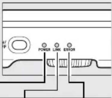
| Status Indicators | POWER (green/yellow), LINK (green), ERROR (orange) LEDs |
| Safety Precautions | Do not disassemble; keep dry; avoid flammable gas; use only approved batteries; follow airline/hospital instructions |
| Compliance | FCC Part 15, IC RSS-210, CE R&TTE Directive (depending on region) |
Frequently Asked Questions - WT-7A NIKON
User questions about WT-7A NIKON
0 question about this device. Answer the ones you know or ask your own.
Ask a new question about this device
Download the instructions for your Uncategorized in PDF format for free! Find your manual WT-7A - NIKON and take your electronic device back in hand. On this page are published all the documents necessary for the use of your device. WT-7A by NIKON.
USER MANUAL WT-7A NIKON
Wireless Transmitter
WT-7
User's Manual
- Read this manual thoroughly before using the camera.
- To ensure proper use of the camera, be sure to read "For Your Safety" (page v).
• After reading this manual, keep it in a readily accessible place for future reference.
What the WT-7 Can Do for You
This manual describes how to attach the WT-7 to the camera and connect the camera to a computer, ftp server, or other device over Ethernet or wireless networks. It also describes the operations that can be performed once a connection is established.
Before connecting the WT-7, confirm that the firmware for the camera and WT-7 have been updated to the latest version. For more information, visit the websites listed on page xvi.
Before using the WT-7 network function, connect the camera to a network.
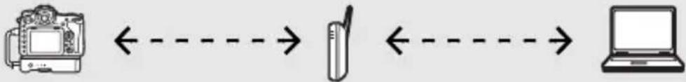
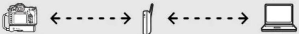
Ethernet Networks

natural_image
Line drawing of a DSLR camera connected to a laptop and an external network device (no text or symbols)For information on connecting to a computer, see page 10. For information on connecting to an ftp server, see page 58.
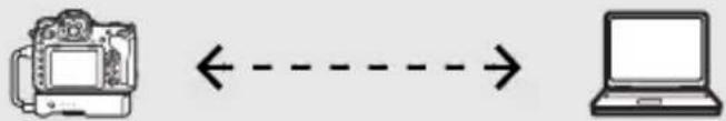
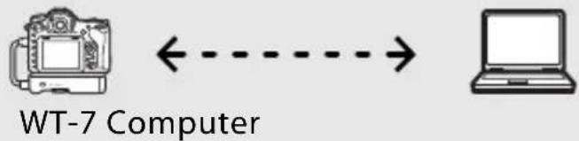
Wireless Networks

natural_image
Illustration of a laptop connected to a DSLR camera via wireless signal waves (no text or symbols)For information on connecting to a computer, see page 18. For information on connecting to an ftp server, see page 65.
Model Name: WT-7 (N1504) Model Name: WT-7A (N1534) Model Name: WT-7B (N1535) Model Name: WT-7C (N1536)
Once a network connection has been established, you can:
Upload existing photos and movies
Image Transfer (32)

FTP Upload (78)
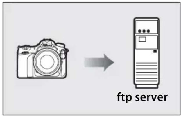
flowchart
graph LR
    A["Camera"] --> B["FTP Server"]
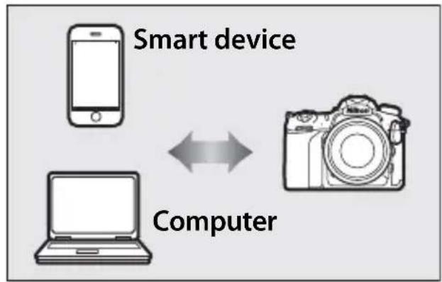
Take or browse photos remotely
Camera Control (37)
HTTP Server (40)
flowchart
graph LR
    A["Smart device"] --> B["Computer"]
    C["Laptop"] <--> B
Nikon User Support for India and Australia
Contact a Nikon representative for technical assistance with the operation of your Nikon product or products. For information on the Nikon representatives in your area, visit http://www.nikon-asia.com/support.
Nikon Manual Viewer 2
Install the Nikon Manual Viewer 2 app on your smartphone or tablet to view Nikon digital camera manuals, anytime, anywhere. Nikon Manual Viewer 2 can be downloaded free of charge from the App Store and Google Play. Download of the app and any product manuals requires an Internet connection, for which fees may be levied by your phone or Internet service provider.
Trademark Information
IOS is a trademark or registered trademark of Cisco Systems, Inc., in the United States and/or other countries and is used under license. Windows is either a registered trademark or a trademark of Microsoft Corporation in the United States and/or other countries. Mac, OS X, iPhone, and iPad are registered trademarks of Apple Inc. in the United States and/or other countries. XQD is a trademark of Sony Corporation. The SD, SDHC, and SDXC logos are trademarks of the SD-3C, LLC. All other trade names mentioned in this manual or the other documentation provided with this Nikon product are trademarks or registered trademarks of their respective holders.
Memory Cards
Throughout this manual, XQD and SD memory cards are referred to as "memory cards".
Apple Public Source License
This product includes Apple mDNS source code that is subject to the terms of the Apple Public Source License located at URL http://developer.apple.com/opensource/.
This file contains Original Code and/or Modifications of Original Code as defined in and that are subject to the Apple Public Source License Version 2.0 (the 'License'). You may not use this file except in compliance with the License. Please obtain a copy of the License at http://www.opensource.apple.com/license/apsl/ and read it before using this file.
The Original Code and all software distributed under the License are distributed on an 'AS IS' basis, WITHOUT WARRANTY OF ANY KIND, EITHER EXPRESS OR IMPLIED, AND APPLE HEREBY DISCLAIMS ALL SUCH WARRANTIES, INCLUDING WITHOUT LIMITATION, ANY WARRANTIES OF MERCHANTABILITY, FITNESS FOR A PARTICULAR PURPOSE, QUIET ENJOYMENT OR NON-INFRINGEMENT. Please see the License for the specific language governing rights and limitations under the License.
For Your Safety
To prevent damage to your Nikon product or injury to yourself or to others, read the following safety precautions in their entirety before using this equipment. Keep these safety instructions where all those who use the product will read them.
The consequences that could result from failure to observe the precautions listed in this section are indicated by the following symbol:

This icon marks warnings, information that should be read before using this Nikon product to prevent possible injury.
WARNINGS
Do not disassemble
Touching the product's internal parts could result in injury. In the event of malfunction, the product should be repaired only by a qualified technician. Should the product break open as the result of a fall or other accident, remove the battery and/or AC adapter and then take the product to a Nikon-authorized service center for inspection.
⚠️ Turn off immediately in the event of malfunction
Should you notice smoke or an unusual smell coming from the equipment, immediately unplug the AC adapter and remove the battery, taking care to avoid burns. Continued operation could result in injury. After removing the battery, take the equipment to a Nikon-authorized service representative for inspection.
⚠️ Do not use in the presence of flammable gas
Do not use electronic equipment in the presence of flammable gas, as this could result in explosion or fire.
⚠️ Keep dry
Do not immerse in or expose to water or rain. Failure to observe this precaution could result in injury or product malfunction due to fire or electric shock.
⚠️ Do not handle with wet hands
Failure to observe this precaution could result in electric shock.
⚠️ Do not handle the power cable or go near the charger during thunderstorms
Failure to observe this precaution could result in electric shock.
⚠️ Keep out of reach of children
Failure to observe this precaution could result in injury. In addition, note that small parts constitute a choking hazard. Should a child swallow any part of this equipment, consult a physician immediately.
Do not remain in contact with the wireless transmitter, battery, or charger for extended periods while the devices are on or in use
Parts of the device become hot. Leaving the device in direct contact with the skin for extended periods may result in low-temperature burns.
Do not leave the product where it will be exposed to extremely high temperatures, such as in an enclosed automobile or in direct sunlight
Failure to observe this precaution could cause damage or fire.
⚠️ Observe proper precautions when handling batteries
Batteries may leak, overheat, rupture, or catch fire if improperly handled. Observe the following precautions when handling batteries for use in this product:
- Use only batteries approved for use in this equipment.
- Do not short or disassemble the battery.
- Do not expose the battery or the device in which it is inserted to powerful physical shocks.
- Be sure the product is off before replacing the battery. If you are using an AC adapter, be sure it is unplugged.
- Do not attempt to insert the battery upside down or backwards.
- Do not expose the battery to flame or to excessive heat.
- Do not immerse in or expose to water.
- Replace the terminal cover when transporting the battery. Do not transport or store the battery with metal objects such as necklaces or hairpins.
- Batteries are prone to leakage when fully discharged. To avoid damage to the product, be sure to remove the battery when no charge remains.
- When the battery is not in use, attach the terminal cover and store in a cool, dry place.
- The battery may be hot immediately after use or when the product has been used on battery power for an extended period. Before removing the battery turn the wireless transmitter off and allow the battery to cool.
- Discontinue use immediately should you notice any changes in the battery, such as discoloration or deformation.
⚠ Use appropriate cables
When connecting cables to the input and output jacks, use only the cables provided or sold by Nikon for the purpose to maintain compliance with product regulations.
⚠️ Follow the instructions of airline and hospital personnel
Notices
- No part of the manuals included with this product may be reproduced, transmitted, transcribed, stored in a retrieval system, or translated into any language in any form, by any means, without Nikon's prior written permission.
- Nikon reserves the right to change the appearance and specifications of the hardware and software described in these manuals at any time and without prior notice.
- Nikon will not be held liable for any damages resulting from the use of this product.
- While every effort has been made to ensure that the information in these manuals is accurate and complete, we would appreciate it were you to bring any errors or omissions to the attention of the Nikon representative in your area (address provided separately).
This product is controlled by the United States Export Administration Regulations (EAR). The permission of the United States government is not required for export to countries other than the following, which as of this writing are subject to embargo or special controls: Cuba, Iran, North Korea, Sudan, and Syria (list subject to change).
The use of wireless devices may be prohibited in some countries or regions. Contact a Nikon-authorized service representative before using the wireless features of this product outside the country of purchase.
Copyright
Comply with copyright notices. Under copyright law, photographs or recordings of copyrighted works made with the camera can not be used without the permission of the copyright holder. Exceptions apply to personal use, but note that even personal use may be restricted in the case of photographs or recordings of exhibits or live performances.
CAUTION
RISK OF EXPLOSION IF BATTERY IS REPLACED BY AN INCORRECT TYPE.
DISPOSE OF USED BATTERIES ACCORDING TO THE INSTRUCTIONS.
Security
Although one of the benefits of this product is that it allows others to freely connect for the wireless exchange of data anywhere within its range, the following may occur if security is not enabled:
- Data theft: Malicious third-parties may intercept wireless transmissions to steal user IDs, passwords, and other personal information.
- Unauthorized access: Unauthorized users may gain access to the network and alter data or perform other malicious actions. Note that due the design of wireless networks, specialized attacks may allow unauthorized access even when security is enabled.
Notice for Customers in the U.S.A. and Canada
This device complies with Part 15 of FCC Rules and Canada's Industry Canada licence-exempt RSSs. Operation is subject to the following two conditions: (1) this device may not cause interference, and (2) this device must accept any interference, including interference that may cause undesired operation of the device.
Nikon WT-7A
FCC ID: CGJ1252EA
IC: 4634A-1252EA
FCC CAUTION
- Changes or modifications not expressly approved by the party responsible for compliance could void the user's authority to operate the equipment.
- The FCC requires the user to be notified that any changes or modifications made to this device that are not expressly approved by Nikon Corporation may void the user's authority to operate the equipment.
FCC Radio Frequency Interference Statement
Note: This equipment has been tested and found to comply with the limits for a Class B digital device, pursuant to part 15 of the FCC Rules. These limits are designed to provide reasonable protection against harmful interference in a residential installation. This equipment generates, uses and can radiate radio frequency energy and, if not installed and used in accordance with the instructions, may cause harmful interference to radio communications.
However, there is no guarantee that interference will not occur in a particular installation. If this equipment does cause harmful interference to radio or television reception, which can be determined by turning the equipment off and on, the user is encouraged to try to correct the interference by one or more of the following measures:
- Reorient or relocate the receiving antenna.
- Increase the separation between the equipment and receiver.
- Connect the equipment into an outlet on a circuit different from that to which the receiver is connected.
- Consult the dealer or an experienced radio/TV technician for help.
Notes on 5GHz band use
- 5.15-5.25GHz band is restricted to indoor operations only.
- High-power radars are allocated as primary users (i.e. priority users) of the bands 5250-5350 MHz and 5650-5850 MHz and that these radars could cause interference and/or damage to LE-LAN devices.
Compliance with FCC requirement 15.407(c)
Data transmission is always initiated by software, which is the passed down through the MAC, through the digital and analog baseband, and finally to the RF chip. Several special packets are initiated by the MAC. These are the only ways the digital baseband portion will turn on the RF transmitter, which it then turns off at the end of the packet. Therefore, the transmitter will be on only while one of the aforementioned packets is being transmitted. In other words, this device automatically discontinue transmission in case of either absence of information to transmit or operational failure.
Compliance with IC(RSS-210§A9.4.4)
Compliance with IC requirement RSS-210 A9.4.4 Data transmission is always initiated by software, which is the passed down through the MAC, through the digital and analog baseband, and finally to the RF chip. Several special packets are initiated by the MAC. These are the only ways the digital baseband portion will turn on the RF transmitter, which it then turns off at the end of the packet. Therefore, the transmitter will be on only while one of the aforementioned packets is being transmitted. In other words, this device automatically discontinue transmission in case of either absence of information to transmit or operational failure.
Co-location
This transmitter must not be co-located or operated in conjunction with any other antenna or transmitter.
FCC/IC RF Exposure Statement
The available scientific evidence does not show that any health problems are associated with using low power wireless devices. There is no proof, however, that these low power wireless devices are absolutely safe. Low power Wireless devices emit low levels of radio frequency energy (RF) in the microwave range while being used. Whereas high levels of RF can produce health effects (by heating tissue), exposure of low-level RF that does not produce heating effects causes no known adverse health effects. Many studies of low-level RF exposures have not found any biological effects. Some studies have suggested that some biological effects might occur, but such findings have not been confirmed by additional research. WT-7A has been tested and found to comply with FCC radiation exposure limits set forth for an uncontrolled environment and meets the FCC radio frequency (RF) Exposure Guidelines.
Nikon Inc.,
1300 Walt Whitman Road, Melville, New York
11747-3064, U.S.A. Tel.: 631-547-4200
Notice for Customers in Europe
R&TTE Directive

We, the manufacturer (Nikon Corporation) hereby declare that this Wireless Transmitter (WT-7) is in compliance with the essential requirements and other relevant provisions of Directive 1999/5/EC.
| AT | BE | BG | CY | CZ | DK | EE | FI |
| FR DE | GR HU IE | IT LV LT | |||||
| LU MT | NL PL PT | RO SK SI | |||||
| ES SE | GB IS LI | NO CH TR | |||||
| HR |
Symbol for Separate Collection in European Countries
This symbol indicates that electrical and electronic equipment is to be collected separately.
The following apply only to users in European countries:

- This product is designated for separate collection at an appropriate collection point. Do not dispose of as household waste.
- Separate collection and recycling helps conserve natural resources and prevent negative consequences for human health and the environment that might result from incorrect disposal.
- For more information, contact the retailer or the local authorities in charge of waste management.
Declaration of Conformity
A copy of the original DoC for our products as it relates to R&TTE can be found at the following website:
http://imaging.nikon.com/support/pdf/DoC_WT-7.pdf
This device complies with radio-frequency regulations. The content of certification labels not affixed to the device is given below.
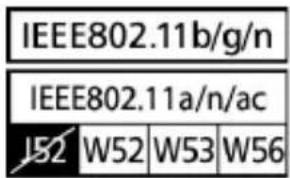
Available Channels
The WT-7 is available in four versions, each destined for use in a different region in compliance with local regulations governing the use of wireless devices (for information on countries not listed in the following table, contact a Nikon representative). Use each model only in the region for which it is intended.
| Version For use in | Channels | ||
| 2.4 GHz band 5 GHz band | |||
| WT-7 | The 32 countries of the EU-EFTA (Austria, Belgium, Bulgaria, Croatia, Cyprus, the Czech Republic, Denmark, Estonia, Finland, France, Germany, Greece, Hungary, Iceland, Ireland, Italy, Latvia, Liechtenstein, Lithuania, Luxembourg, Malta, the Netherlands, Norway, Poland, Portugal, Romania, Slovakia, Slovenia, Spain, Sweden, Switzerland, the United Kingdom), Australia, Japan, New Zealand, Saudi Arabia, South Africa, Thailand, Turkey | 1–13 | 36–64, 100–140 |
| WT-7A | Argentina, Brazil, Canada, Chile, India, Mexico, Panama, Taiwan, U.S.A. | 1–11 | 36–64, 149–165 |
| WT-7B | Korea, Russia, Singapore 1–13 36–64 | ||
| WT-7C | China, Hong Kong, Malaysia 1–13 149–165 | ||
5GHz band
The channels available for 5GHz band are listed below.
Notices
| Version Location Mode | Channels | |||||
| W52 W53 W56 W58 | ||||||
| 36-48 52-64 100-140 149-165 | ||||||
| WT-7 | Indoor | Infrastructure | √ | √ | √ | — |
| Access point — | — | — | — | — | ||
| Outdoor | Infrastructure Prohibited Prohibited | √— | ||||
| Access point — | — | — | — | — | ||
| WT-7A | Indoor | Infrastructure | √ | √ | — | √ |
| Access point — | — | — | — | — | ||
| Outdoor | Infrastructure Prohibited Prohibited — | √ | ||||
| Access point — | — | — | — | — | ||
| WT-7B | Indoor | Infrastructure | √ | √ | — | — |
| Access point — | — | — | — | — | ||
| Outdoor | Infrastructure | √ | √ | — | — | |
| Access point — | — | — | — | — | ||
| WT-7C | Indoor | Infrastructure — | — | — | — | √ |
| Access point — | — | — | — | — | ||
| Outdoor | Infrastructure — | — | — | — | √ | |
| Access point — | — | — | — | — | ||
Table of Contents
What the WT-7 Can Do for You ....ii
For Your Safety ......v
Notices......vii
Introduction 1
Parts of the WT-7 2
Getting Ready 4
Supported Network Functions ....8
Transfer, Control, and HTTP 10
Ethernet Connections.... 10
Step 1: Connecting the Equipment.... 11
Step 2: Configuring the Hardware for Ethernet Connections.... 12
Step 3: The Connection Wizard.... 13
Step 4: Pairing ....16
Wireless Connections.... 18
Step 1: Readying the Equipment.... 20
Step 2: Enable Camera Wireless.... 21
Step 3: The Connection Wizard....22
Step 4: Network Settings.... 29
Image Transfer.... 32
Camera Control 37
HTTP Server 40
Computer and Android Web Browsers......46
iPhone Web Browsers....53
Ethernet Connections 58
Step 1: Connecting the Hardware ....59
Step 2: Configuring the Hardware for Ethernet Connections ....60
Step 3: The Connection Wizard ....61
Wireless Connections.... 65
Step 1: Connecting the Equipment ....66
Step 2: Enable Camera Wireless ....67
Step 3: The Connection Wizard ....68
Step 4: Network Settings ....75
FTP Upload....78
Menu Guide 83
Choose Hardware 83
Network Settings 84
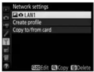
The Profile List 84
Create Profile....84
Copy to/from Card 85
Deleting Network Profiles ....85
Editing Network Profiles ....86
Options....89
Auto Send....89
Delete After Send 89
Send File As....89
Overwrite If Same Name....90
Protect If Marked for Upload....90
Send Marking (FTP Upload Mode Only)....90
Send Folder....90
Deselect All?......91
HTTP User Settings 91
Battery Info....91
Power Saving....91
Auto Power off Delay....92
MAC Address 92
Firmware Version 92
Appendices 93
Creating Profiles on a Computer 93
Creating an FTP Server 95
Manual Profile Creation....103
Troubleshooting ....105
Specifications....107
Index....110

Background Knowledge
This manual assumes basic knowledge of ftp servers and local area networks (LANs). For more information on installing, configuring, and using devices in a network, contact the manufacturer or network administrator.

Illustrations
The appearance and content of the software and operating system dialogs, messages, and displays shown in this manual may vary with the operating system used. For information on basic computer operations, see the documentation provided with the computer or operating system.

Camera Controls
The camera operations described in this manual are those for the D500. Operations for other cameras may differ.

Life-Long Learning
As part of Nikon's "Life-Long Learning" commitment to ongoing product support and education, continually-updated information is available on-line at the following sites:
- For users in the U.S.A.: http://www.nikonusa.com/
- For users in Europe and Africa: http://www.europe-nikon.com/support/
- For users in Asia, Oceania, and the Middle East: http://www.nikon-asia.com/Visit these sites to keep up-to-date with the latest product information, tips, answers to frequently-asked questions (FAQs), and general advice on digital imaging and photography. Additional information may be available from the Nikon representative in your area. See the following URL for contact information: http://imaging.nikon.com/
Introduction
Thank you for your purchase of a WT-7 wireless transmitter for compatible Nikon digital cameras. Please read this manual thoroughly and keep it where all those who use the product can read it.
The following symbols and conventions are used throughout this manual:

This icon marks cautions, information that should be read before use to prevent damage to the product.

This icon marks notes, information that should be read before using the device.

This icon marks references to other pages in this manual.
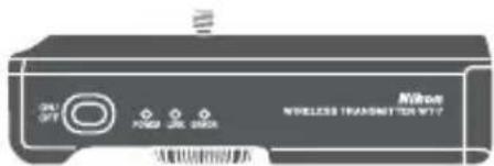
Parts of the WT-7
Parts of the WT-7
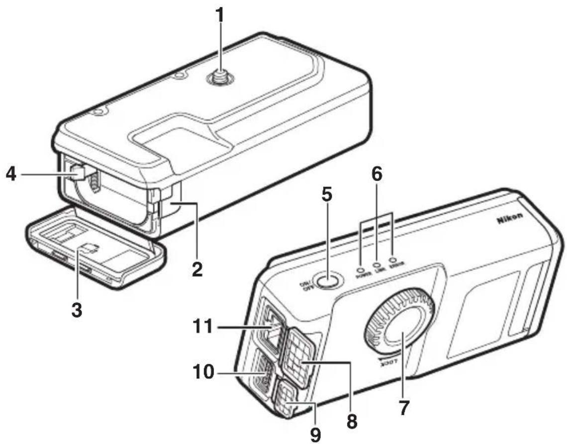
1 Mounting screw....5
2 Power connector cover ...... 7
3 Battery-chamber cover 4
4 Battery latch....4
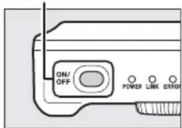
5 Power switch......11, 20, 59, 66
6 Status LEDs......35, 38, 44, 81
POWER (green/yellow), LINK (green), ERROR (orange)
7 Attachment wheel......5
8 Ethernet connector cover
9 USB connector cover
10 USB connector....5
11 Ethernet connector

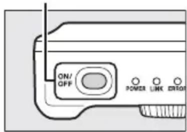
The POWER LED
When the WT-7 is on, the POWER LED glows green to indicate that the battery is fully charged or that an AC adapter is connected. At battery levels below 10%, it will flash to warn that the battery requires charging. When the WT-7 is turned off, the POWER LED briefly turns yellow as the product powers down.

Supplied Accessories
The following accessories are supplied with the WT-7 (batteries such as the EN-EL15 are not supplied):
□User's Manual (this manual)
USB cable B
□Warranty
□UF3-RU14 USB cable gasket
□CF-WT7 case
☐UF-7 USB cable connector cover
AN-CP24 Strap

USB Cable Gaskets and Connector Covers
The USB cable gaskets and connector covers prevent accidental disconnections. Attach as shown below.
When connecting the USB cable to a camera, attach the supplied UF-7 cable connector cover as shown.
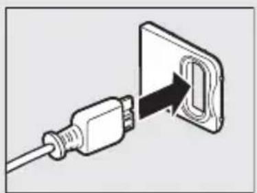
natural_image
Diagram of a plug inserted into a socket socket (no text or symbols)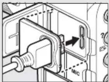
When connecting the USB cable to the WT-7, attach the supplied UF3-RU14 cable gasket as shown.
natural_image
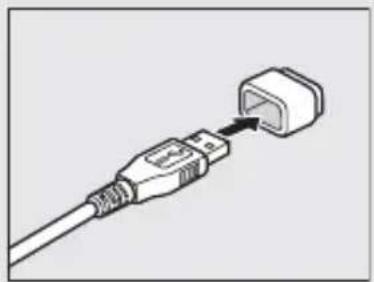
Illustration of a cable with an attached plug (no text or symbols)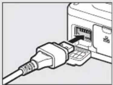
natural_image
Line drawing of a USB cable inserted into a device (no text or symbols visible)Getting Ready
Inserting the Battery
The WT-7 takes one EN-EL15 rechargeable Li-ion battery. Insert the battery as described below.
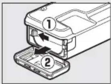
1 Open the battery-chamber cover.
Unlatch the cover by sliding it as shown (①).
Open the cover (②).
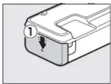
natural_image
Diagram of a device casing with a labeled component (no text or symbols present)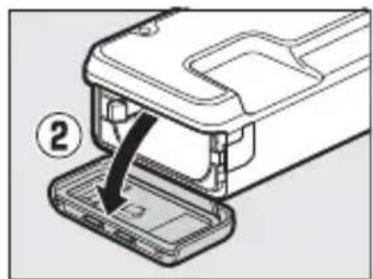
natural_image
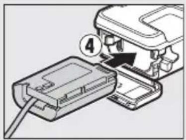
Diagram of a device with an open lid and a black arrow pointing to a component, labeled with number 2 (no text or symbols on the diagram itself)2 Insert the battery.
Using the battery to keep the battery latch pressed to one side, slide the battery in until the latch clicks back into place. For safety precautions and information on charging the battery, see the battery and charger manuals.
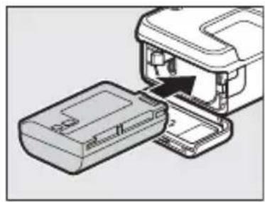
natural_image
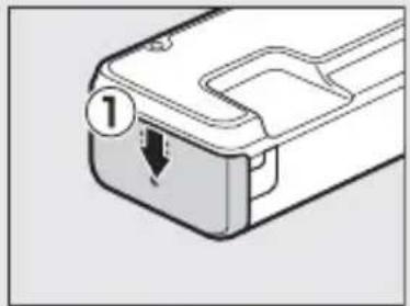
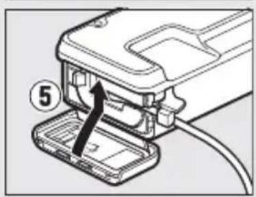
Diagram of a device being inserted into a housing, showing internal components and a black arrow indicating the insertion direction (no text or symbols present)3 Close the battery-chamber cover.
Reverse the instructions in Step 1 to close and latch the cover as shown. Be sure the cover is securely latched.
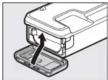
natural_image
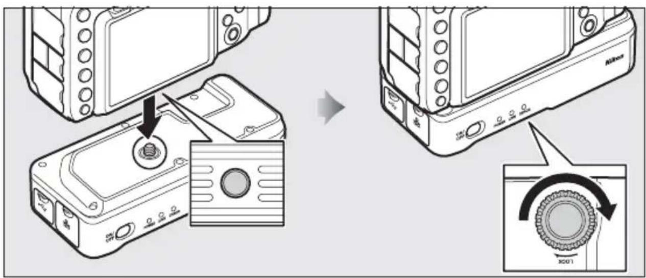
Diagram of a device with an open lid and arrow indicating insertion or positioning (no text or symbols)Attaching the WT-7
After checking that the camera is off, align the WT-7 mounting screw with the camera tripod socket and tighten by rotating the attachment wheel in the direction shown by the LOCK arrow.
Getting Ready
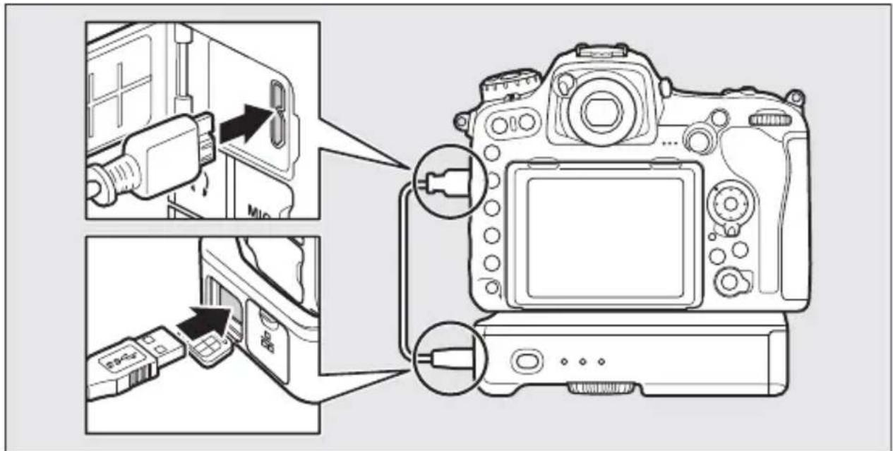
Connecting the USB Cable
Connect the WT-7 to the camera using the supplied USB cable.
The Wireless Transmitter Utility
The Wireless Transmitter Utility is used for pairing in image transfer and camera control modes (16) and can also help create network profiles (93). You can install the utility after downloading it from the following website:
http://downloadcenter.nikonimglib.com/
Be sure to use the latest versions of the Wireless Transmitter Utility and the camera firmware.
Removing the Battery
Being careful not to drop the battery, open the WT-7 battery-chamber cover and remove the battery as shown at right.
Stand-By Mode
When the WT-7 is disconnected from the camera or the camera is turned off, the WT-7 will turn off automatically after the delay chosen for Network > Options > Auto power off delay in the setup menu (📖 92), reducing the drain on the battery.

Battery Level
The level of the battery inserted in the WT-7 can be determined by connecting the WT-7 to the camera (☐5) and checking the battery level using the Options > Battery info in the Network menu (☐91).

Using an AC Adapter
To prevent loss of power when adjusting settings or transmitting images, use a fully-charged battery or an optional EP-5B power connector and EH-5b AC adapter. An optional EH-5/EH-5a AC adapter can also be used. Insert the power connector as shown below.
1 Unlatch the battery-chamber cover (①).
2 Open the battery-chamber (②) and power connector covers (③).
3Using the power connector to keep the battery latch pressed to one side, slide the connector in until the latch clicks back into place (④).
4Position the power connector so that the cord passes through the power connector slot and close the battery-chamber cover (⑤). Be sure that the cover is securely latched.
natural_image
Diagram of a device casing with a labeled component (1) and directional arrow, no text or symbols present.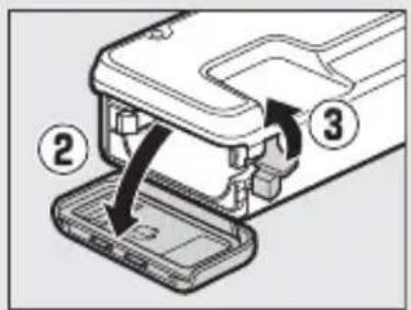
Supported Network Functions
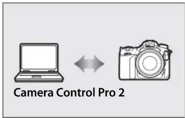
The WT-7 wireless transmitter connects the camera to Ethernet and wireless networks. Photographs on the camera can then be transmitted to a computer or ftp server and the camera controlled remotely from a computer. The WT-7 supports the following functions:
| FTP upload(78) | Upload existing photos and movies to a computer or ftp server, or upload new photos as they are taken. |
| Image transfer(32) | |
| Camera control(37) | Control the camera using optional Camera Control Pro 2 software and save new photos and movies directly to the computer. |
| HTTP server(40) | View and take pictures remotely using a browser-equipped computer or smart device. |
Before data can be transferred over a wireless or Ethernet network, the camera must be supplied with a network profile providing information on the host computer or ftp server.
√Choosing a Power Source
To prevent the camera or WT-7 powering off unexpectedly during setup or data transfer, use fully-charged batteries or optional AC adapters designated for use with the camera or WT-7. For more on camera power sources, see the camera manual.
FTP Servers
Servers can be configured using standard ftp services available with supported operating systems, such as IIS (Internet Information Services). Connection to computers on other networks via a router, Internet ftp connections and ftp servers running third-party software are not supported.
Ethernet Connection
No adjustments to wireless LAN settings are required when the camera is connected to a LAN by an Ethernet cable.
HTTP Server Mode
Internet connections are not supported in http server mode.
Routers
Connection to computers on other networks via a router is not supported.
Firewall Settings
TCP ports 21 and 32768 through 61000 are used for ftp, TCP ports 22 and 32768 through 61000 for sftp, and TCP port 15740 and UDP port 5353 for connections to computers. File transfer may be blocked if the server firewall is not configured to allow access to these ports.
Transfer, Control, and HTTP
Ethernet Connections
Follow the steps below to connect via an Ethernet network. For information on wireless connections, see page 18.
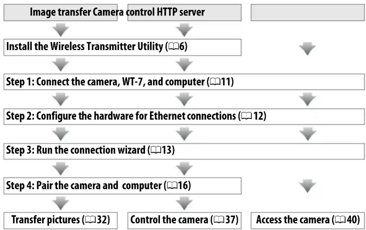
flowchart
graph TD
    A["Image transfer Camera"] --> B["Install the Wireless Transmitter Utility (6)"]
    C["control HTTP server"] --> B
    B --> D["Step 1: Connect the camera, WT-7, and computer (11)"]
    D --> E["Step 2: Configure the hardware for Ethernet connections (12)"]
    E --> F["Step 3: Run the connection wizard (13)"]
    F --> G["Step 4: Pair the camera and computer (16)"]
    G --> H["Transfer pictures (32)"]
    G --> I["Control the camera (37)"]
    I --> J["Access the camera (40)"]
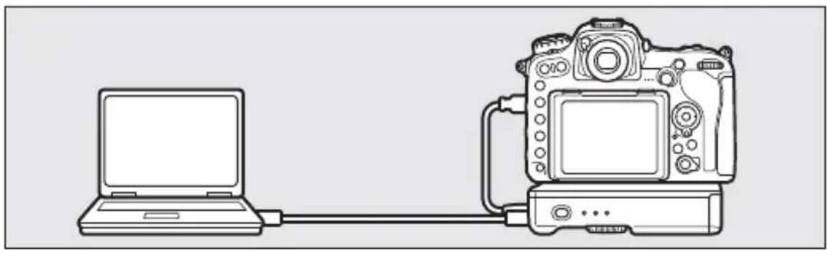
Step 1: Connecting the Equipment
Before proceeding with the following steps, start the computer and log in.
1 Insert a memory card.
Turn the camera off and insert a memory card (do not turn the camera off or disconnect the Ethernet cable while data are being transferred to the computer). This step can be omitted in camera control mode (☐37).
2 Attach the WT-7 (☐ 5).
3 Connect an Ethernet cable.
Connect the Ethernet cable as shown below. Do not use force or insert the connectors at an angle.

natural_image
Line drawing of a laptop connected to a DSLR camera via cable (no text or symbols)4 Turn the camera on.
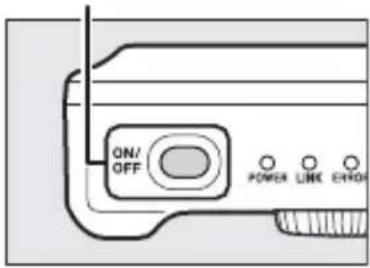
Rotate the power switch to turn the camera on.
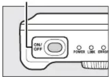
5 Press the power switch for about a second to turn the WT-7 on.
Power switch
Step 2: Configuring the Hardware for Ethernet Connections
Configure the WT-7 for use with Ethernet networks.
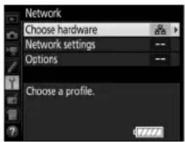
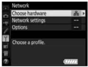
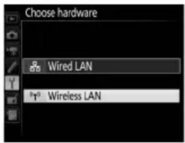
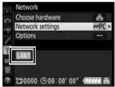
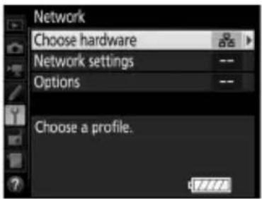
1 Select Choose hardware.
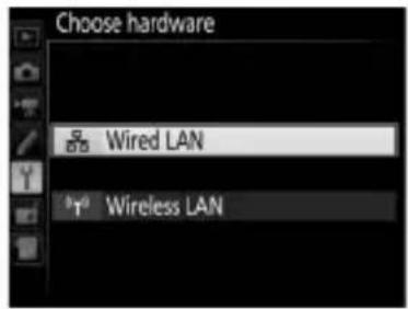
In the setup menu, select Network, then highlight Choose hardware and press ⬆. The menu offers a choice of Wired LAN and Wireless LAN.
2 Select Wired LAN.
Highlight Wired LAN and press Ⓞ to select the highlighted option and return to the network menu.
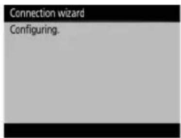
Step 3: The Connection Wizard
Follow the on-screen instructions to create a network profile.
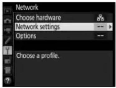
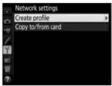
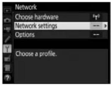
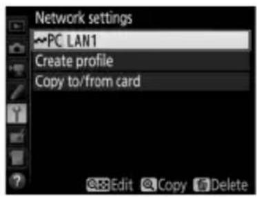
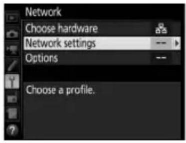
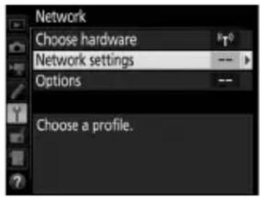
1 Display network profiles.
In the network menu, highlight Network settings and press 🔒 to display the profiles list and other network settings.
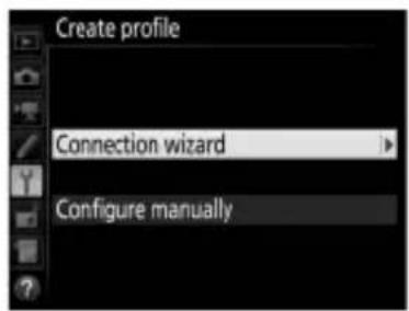
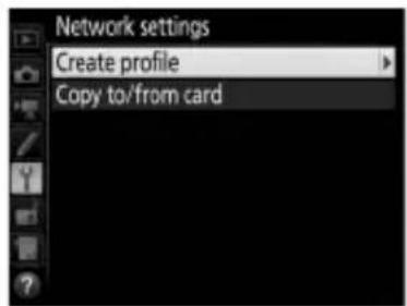
2 Select Create profile.
Highlight Create profile and press 🔒. Note that if the list already contains nine profiles, you will need to delete an existing profile using the ⏻ (FORMAT) button before proceeding (85).
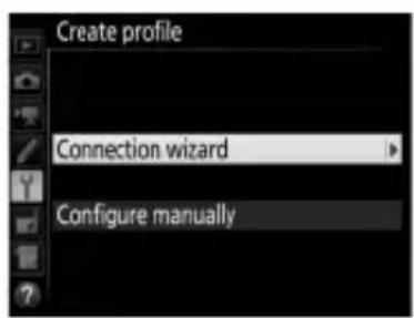
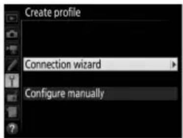
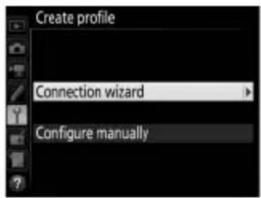
3 Start the connection wizard.
Highlight Connection wizard and press ⬆ to start the connection wizard.
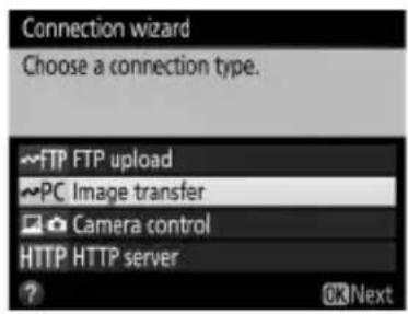
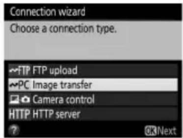
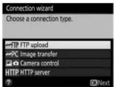
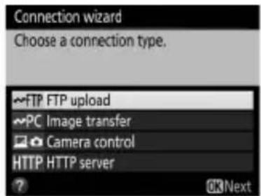
4 Choose a connection type (8).
Highlight Image transfer, Camera control, or HTTP server and press 🔒.
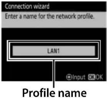
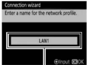
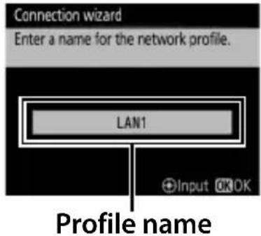
5 Name the new network profile.
A default profile name will be displayed; to edit or change the name as described in the camera manual, press the center of the multi selector (if the camera is a touch-screen model, you can enter characters by tapping the letters on the on-screen keyboard). The profile name will appear in the Network > Network settings list in the camera setup menu. Press Ⓞ to proceed to the next step when entry is complete.
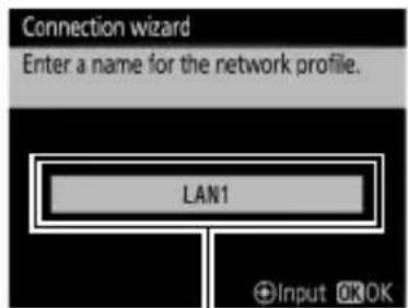
Profile name
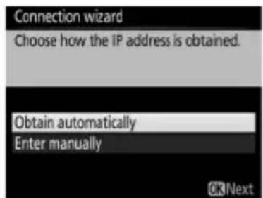
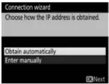
6 Obtain or select an IP address.
Highlight one of the following options and press Ⓞ.
- Obtain automatically: Select this option if the network is configured to supply the IP address automatically.
- Enter manually: When prompted, enter an IP address and subnet mask by pressing 🔒 and ➕ to highlight segments and 🔊 and ➕ to change. Press Ⓞ to proceed when entry is complete.
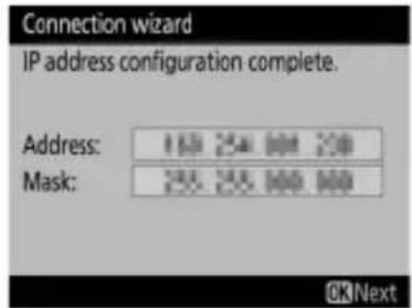
7 Choose your next step.
The IP address will be displayed; press Ⓞ. Your next step depends on the connection type selected in Step 4 on page 13:
If you chose Image transfer or Camera control, proceed to page 16.

If you chose HTTP server, proceed to Step 8.
8 Exit the wizard.
Highlight one of the following options and press Ⓞ.
- Connect and exit wizard: Save the new network profile and connect to the server.
- Exit wizard: Save the new network profile and exit.
Proceed to "HTTP Server" (☐40).
Routers
Connection to computers on other networks via a router is not supported.
Step 4: Pairing
If you selected Image transfer or Camera control in Step 4 of the connection wizard (13), pair the camera with the computer as described below. Pairing allows the computer to connect to the camera.
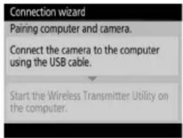
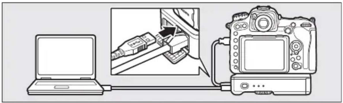
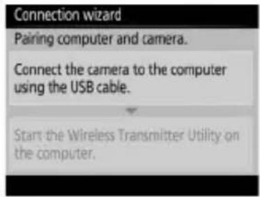
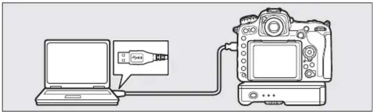
1 Connect the camera to the computer via USB.
Disconnect the USB cable from the WT-7 and connect it to the computer.

natural_image
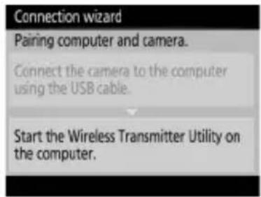
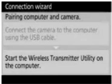
Line drawing of a DSLR camera connected to a laptop via USB cable (no text or symbols)2 Start the Wireless Transmitter Utility.
When prompted, start the copy of the Wireless Transmitter Utility installed on the computer. Pairing will begin automatically.
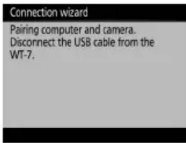
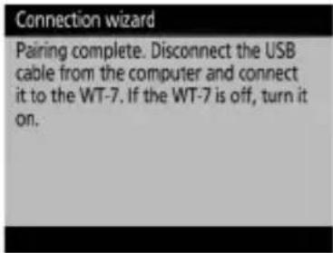
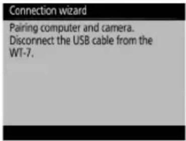
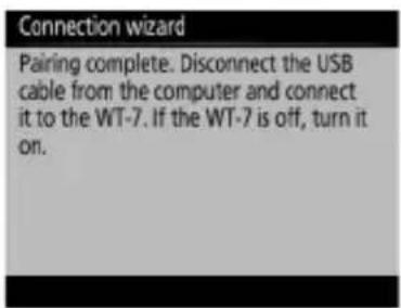
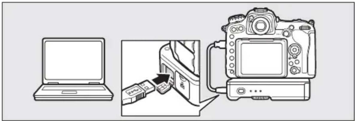
3 Disconnect the camera.
The message at right will be displayed when pairing is complete. Disconnect the USB cable from the computer and reconnect it to the WT-7.
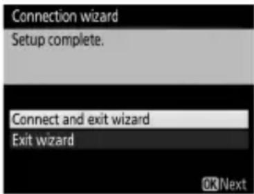
4 Exit the wizard.
Highlight one of the following options and press Ⓞ.
- Connect and exit wizard: Save the new network profile and connect to the server.

- Exit wizard: Save the new network profile and exit.
Proceed to "Image Transfer" (☐32) or "Camera Control" (☐37).
Wireless Connections
Follow the steps below to connect to a wireless network.
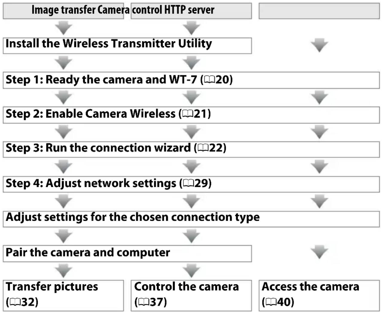
flowchart
graph TD
    A["Image transfer Camera"] --> B["Install the Wireless Transmitter Utility"]
    C["control HTTP server"] --> B
    B --> D["Step 1: Ready the camera and WT-7 (20)"]
    D --> E["Step 2: Enable Camera Wireless (21)"]
    E --> F["Step 3: Run the connection wizard (22)"]
    F --> G["Step 4: Adjust network settings (29)"]
    G --> H["Adjust settings for the chosen connection type"]
    H --> I["Pair the camera and computer"]
    I --> J["Transfer pictures (32)"]
    I --> K["Control the camera (37)"]
    I --> L["Access the camera (40)"]

Infrastructure and Access Point Modes
Connections to wireless networks may be in infrastructure or access point mode.
Infrastructure mode: Connection via a wireless LAN access point.
flowchart
graph LR
    A["Printer"] <--> B["Telephone Receiver"]
    B <--> C["Laptop"]
WT-7 Wireless LAN access point Computer or
smart device
Access point mode: The camera serves as an access point for direct connection to a computer or smart device.
flowchart
graph LR
    A["Printer"] <--> B["Laptop"]
WT-7 Computer or
smart device

Wireless LANs
These instructions are intended for customers with an existing wireless LAN, and in the case of infrastructure networks assume that the computer and access point are already connected to the network.
Step 1: Readying the Equipment
After starting the computer and logging in, ready the camera and WT-7 as described below.
1 Insert a memory card.
Turn the camera off and insert a memory card (do not turn the camera off while data are being transferred to the computer).
This step can be omitted in camera control mode (☐8).
2 Attach the WT-7 (☐5).
3 Turn the camera on.
Rotate the power switch to turn the camera on.
4 Press the power switch for about a second to turn the WT-7 on.
Power switch
Step 2: Enable Camera Wireless
Ready the camera for connection to a wireless network.
1 Select Choose hardware.
In the setup menu, select Network, then highlight Choose hardware and press ⬆. The menu offers a choice of Wired LAN and Wireless LAN.
2 Select Wireless LAN.
Highlight Wireless LAN and press Ⓞ to select the highlighted option and return to the network menu.
Step 3: The Connection Wizard
Follow the on-screen instructions to create a network profile.
1 Display network profiles.
In the network menu, highlight Network settings and press ⬆ to display the profiles list and other network settings.
2 Select Create profile.
Highlight Create profile and press 🔒. Note that if the list already contains nine profiles, you will need to delete an existing profile using the ⏻ (FORMAT) button before proceeding.

3 Start the connection wizard.
Highlight Connection wizard and press ⬆ to start the connection wizard.
4 Choose a connection type (☐8).
Highlight Image transfer, Camera control, or HTTP server and press OK.
5 Name the new network profile.
A default profile name will be displayed; to edit or change the name as described in the camera manual, press the center of the multi selector (if the camera is a touch-screen model, you can enter characters by tapping the letters on the on-screen keyboard). The profile name will appear in the Network > Network settings list in the camera setup menu. Press Ⓞ to proceed to the next step when entry is complete.
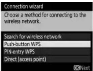
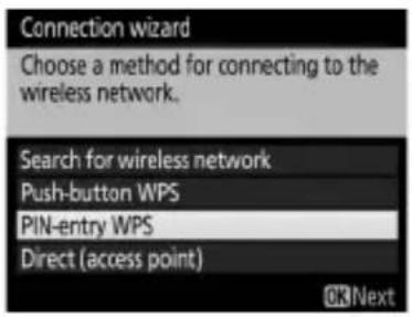
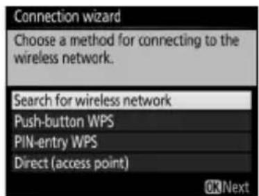
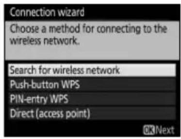
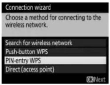
6 Choose a connection method.
Highlight the connection method used by the network and press Ⓞ. More information can be found on the pages listed below.
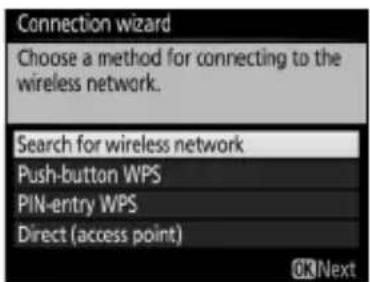
| Search for wireless network | Choose from a list of networks detected by the camera. Proceed to page 24. |
| Push-button WPS | Choose for wireless LAN access points with push-button WPS. Proceed to page 26. |
| PIN-entry WPS | Choose for wireless LAN access points with PIN-entry WPS. Proceed to page 27. |
| Direct (access point) | Connect directly to a host computer or ftp server in access point mode, with the camera serving as an access point. Proceed to page 28. |
■Search for Wireless Network
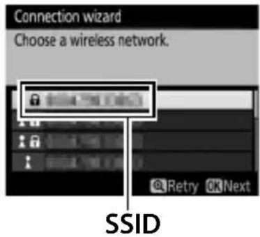
Select Search for wireless network in Step 6 on page 23 to choose from a list of the networks (wireless LAN access points) detected by the camera.

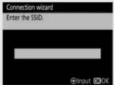
1 Choose a network.
Highlight a network SSID and press Ⓞ (if the desired network is not displayed, press Ⓧ to search again). Encrypted networks are indicated by a 🔒 icon; if the selected network is encrypted, you will be prompted to enter the encryption key as described in Step 2. If the network is not encrypted, proceed to Step 3.

Hidden SSIDs
Networks with hidden SSIDs are indicated by blank entries in the network list. If you highlight a blank entry and press Ⓞ, you will be prompted to provide the network name; press the center of the multi selector, enter a name, and then press Ⓞ to proceed to Step 2.
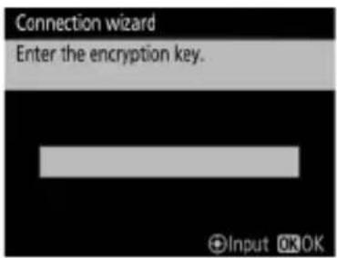
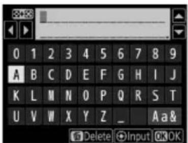
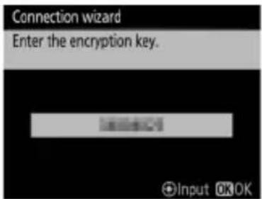
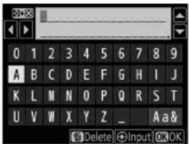
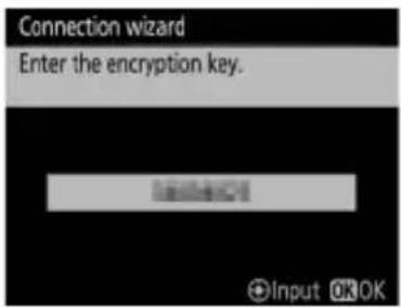
2 Enter the encryption key.
Press the center of the multi selector and enter the encryption key as described in the camera manual (if the camera is a touch-screen model, you can enter characters by tapping the letters on the on-screen keyboard).
Press Ⓞ when entry is complete.
Press Ⓞ to establish a connection.
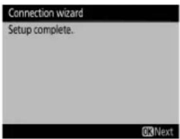
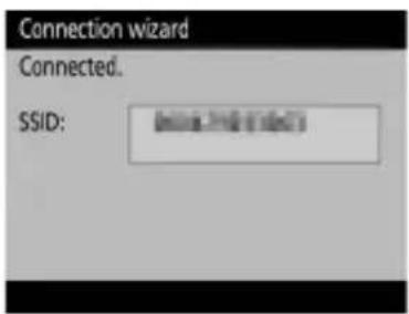
3 Choose your next step.
The message at right is displayed when a connection is established. Proceed to page 29.

■Push-Button WPS
Choose Push-button
WPS in Step 6 on page 23 if the wireless LAN access point uses push-button WPS.
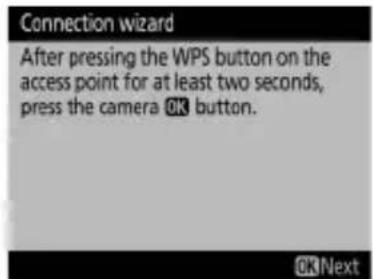
1 Press the WPS button on the wireless LAN access point.
For more information, see the documentation provided with the wireless LAN access point.
2 Press Ⓞ button on the camera.
The camera will connect to the access point automatically.
3 Choose your next step.
The message at right is displayed when a connection is established. Press Ⓞ and proceed to page 29.

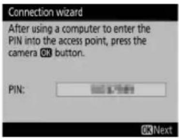
PIN-Entry WPS
Choose PIN-entry WPS in Step 6 on page 23 if the wireless LAN access point uses PIN-entry WPS.

1 Enter the PIN for the wireless LAN access point.
From a computer, enter the PIN for the wireless LAN access point. For more information, see the documentation provided with the wireless LAN access point.
2 Press Ⓞ button on the camera.
The camera will connect to the access point automatically.

3 Choose your next step.
The message at right is displayed when a connection is established. Press Ⓞ and proceed to page 29.
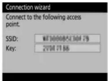
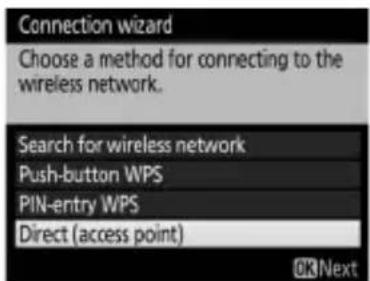
■Direct (Access Point)
Selecting Direct (access point) in Step 6 on page 23 enables access point mode, in which the camera serves as a wireless access point. The camera SSID and encryption key will be displayed in the monitor. On the computer or smart device, enter the SSID and encryption key displayed in the camera monitor. If you selected Image transfer or Camera control mode in Step 4 on page 22, proceed to Step 3 on page 30. If you selected HTTP server mode, proceed to Step 5 on page 31.

If you selected Search for wireless network, Push-button WPS, or PIN-entry WPS in Step 6 on page 23, choose an IP address. If you selected Direct (access point), your next step will depend on the connection type selected in Step 4 on page 22:
- If you selected Image transfer or Camera control mode, proceed to Step 3.
- If you selected HTTP server mode, proceed to Step 5.
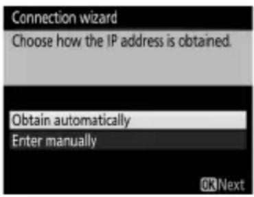
1 Obtain or select an IP address.
Highlight one of the following options and press Ⓞ.
- Obtain automatically: Select this option if the network is configured to supply the IP address automatically.
- Enter manually: When prompted, enter an IP address and subnet mask by pressing ◆ and ▶ to highlight segments and ⬇ and ▼ to change. Press Ⓞ to proceed when entry is complete.
Routers
Connection to computers on other networks via a router is supported only when HTTP server is selected.
MAC Address Filtering
If the network uses MAC address filtering, the filter must be supplied with the MAC address of the WT-7. After attaching the WT-7 to the camera, choose Network > Options > MAC address from the camera setup menu and note the MAC address.
2 Confirm the IP address.
The camera IP address will be displayed as shown at right; press OK. If Image transfer or Camera control is selected, proceed to Step 3; otherwise, proceed to Step 5.
3 Connect the camera to the computer.
Disconnect the USB cable from the WT-7 and connect it to the computer.
natural_image
Line drawing of a DSLR camera connected to a laptop via USB cable (no text or symbols)4 Start the Wireless Transmitter Utility.
When prompted, start the copy of the Wireless Transmitter Utility installed on the computer (6). Pairing will begin automatically.
5 Disconnect the camera.
The message at right will be displayed when pairing is complete. Disconnect the USB cable from the computer and reconnect it to the WT-7.
natural_image
Diagram showing a laptop connected to a camera via a device, with no visible text or symbols.6 Exit the wizard.
Highlight one of the following options and press ⓄK.
- Connect and exit wizard: Save the new network profile and connect to the network.
- Exit wizard: Save the new network profile and exit.
Proceed to "Image Transfer" (☐32), "Camera Control" (☐37), or "HTTP Server" (☐40).
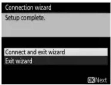
Image Transfer
Image transfer is used to upload photographs and movies to the computer from a camera memory card. The explanation that follows assumes that existing pictures are used.
1 Display network profiles.
In the setup menu, select Network > Network settings to display the profiles list. Image transfer profiles are indicated by a ↗PC icon. Highlight a profile and press Ⓞ to select the highlighted profile and return to the network menu.
The profile name will be displayed in green when a connection is established.
2 View pictures.
Press the ▶ button to view pictures. Display the first picture to be sent in single-image playback or highlight it in the thumbnail list.

natural_image
Illustration of a woman with shoulder-length hair, standing by the sea with a sailboat and mountains in the background (no text or symbols)3 Upload pictures.
Press Ⓞ and the center of the multi selector. A white transfer icon will appear on the picture and upload will begin immediately. The transfer icon turns green during upload, and turns blue when upload is complete. Additional pictures will be uploaded in the order selected.
To upload a picture that has already been uploaded once, press Ⓞ and the center of the multi selector once to remove the blue transfer icon, and then press Ⓞ and the center of the multi selector again to mark the image with a white transfer icon.

natural_image
Illustration of a woman with shoulder-length hair, looking at a lakeside scene with a sailboat and mountains in the background (no text or symbols)
natural_image
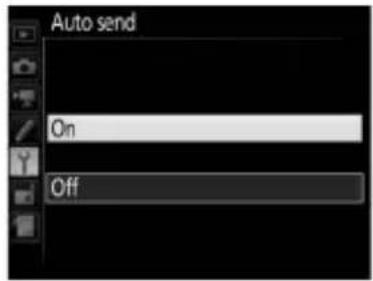
Illustration of a woman with hands on chin, standing by the sea with a sailboat and mountains in the background (no text or symbols)Uploading New Photographs as They Are Taken
To upload new photographs as they are taken, select On for Network > Options > Auto send in the setup menu (☐89).
Interrupting Transmission/Removing Transfer Marking
To cancel transmission of images marked with white or green transfer icons, select the images during playback and press Ⓞ and the center of the multi selector. The transfer icon will be removed.
Any of the following actions will also interrupt transmission:
- Turning the camera off
- Selecting Yes for Network > Options > Deselect all? (91; this option also removes transfer marking from all images)
During Upload
Do not remove the memory card or disconnect the Ethernet cable during upload.
Interval Timer Photography
Upload will be interrupted if the standby timer expires while interval timer photography is in progress. Choose a long standby time before starting the interval timer.
Loss of Signal
Wireless transmission may be interrupted if the signal is lost, but can be resumed by turning the camera off and then on again.
Turning the Camera Off
"Send" marking will be saved if the camera or WT-7 is turned off while transmission is in progress. Transmission of images marked with a "send" icon will resume when the camera or WT-7 is turned on.
Destination Folders
By default, images are uploaded to the following folders:
- Windows: \Users\user name\Pictures\Wireless Transmitter Utility
• Mac: /Users/(user name)/Pictures/Wireless Transmitter Utility
The destination folder can be selected using the Wireless Transmitter Utility.
Transfer Status
During playback, the status of images selected for upload is shown as follows:
: "Send"
Images that have been selected for upload are marked with a white 📋 icon.
: "Sending"
A green 📋 icon is displayed during upload.

natural_image
Illustration of a woman with hands clasped, standing by the sea with mountains and a sailboat in the background (no text or symbols)Image Transfer
: "Sent"
Images that have been uploaded successfully are marked with a blue 🔊 icon.
Network Status
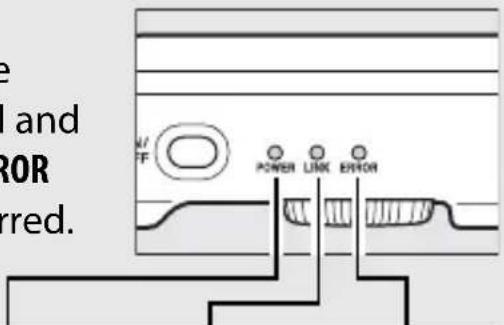
The status of the link between the host and the WT-7 is shown by the status LEDs and by the display in the top level of the network menu.
The Status LEDs
The POWER LED lights when the WT-7 is on. Signal quality is shown by the LINK LED: the faster the LED flashes, the better the signal and the faster data can be transmitted. The ERROR LED flashes to show that an error has occurred.
| Status POWER LINK ERROR | |||
| WT-7 off | ● (off) | ● (off) | ● (off) |
| USB cable not connected | ○ (on) | ● (off) | ● (off) |
| Connecting to host | ○ (on) | ○ (on) | ● (off) |
| Waiting to send or sending data | ○ (on) | flashes) | ● (off) |
| Connection error | ○ (on) | ● (off) | flashes) |
| WT-7 hardware or battery malfunction | flashes) | flashes) | flashes) |
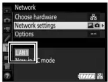
The Status Display
Network status can also be viewed in the top level of the network menu.
Camera Control
Select this option to control the camera from a computer running Camera Control Pro 2 (available separately) and save photographs directly to the computer hard disk instead of the camera memory card (movies will still be saved to the camera memory card; insert a memory card before shooting movies). Note that the camera standby timer do not turn off when the camera is in camera control mode.
1 Display network profiles.
In the setup menu, select Network > Network settings to display the profiles list. Camera control profiles are indicated by a 📄 icon. Highlight a profile and press Ⓞ to select the highlighted profile and return to the network menu.
The profile name will be displayed in green when a connection is established.
2 Start Camera Control Pro 2.
Start the copy of Camera Control Pro 2 (available separately) installed on the host computer. For information on using Camera Control Pro 2, see the Camera Control Pro 2 manual (pdf).

Ethernet Networks
Do not disconnect the Ethernet cable while the camera is on.

Wireless Networks
Operations may take longer on wireless networks. If the signal is disrupted while pictures are being transferred to Camera Control Pro 2, the LED on the WT-7 will flash orange; turn the camera off and then on again. Transfer will resume when the connection is re-established. Note that transfer can not be resumed if you turn the camera off again before transfer is complete.

Network Status
The status of the link between the host and the WT-7 is shown by the status LEDs and by the display in the top level of the network menu.
The Status LEDs
The POWER LED lights when the WT-7 is on. Signal quality is shown by the LINK LED: the faster the LED flashes, the better the signal and the faster data can be transmitted. The ERROR LED flashes to show that an error has occurred.
| Status POWER LINK ERROR | |||
| WT-7 off | ● (off) | ● (off) | ● (off) |
| USB cable not connected | ○ (on) | ● (off) | ● (off) |
| Connecting to host | ○ (on) | ○ (on) | ● (off) |
| Waiting to send or sending data | ○ (on) | ★ (flashes) | ● (off) |
| Connection error | ○ (on) | ● (off) | ★ (flashes) |
| WT-7 hardware or battery malfunction | ★ (flashes) | ★ (flashes) | ★ (flashes) |
The Status Display
Network status can also be viewed in the top level of the network menu.
HTTP Server
Select HTTP server to view the pictures on the camera memory card or take photographs from the web browser on a computer or smart device (see page 45 for system requirements). Up to five users can access the camera at one time, although only one can take photographs or edit text. Note that the standby timer do not turn off automatically when the camera is in http server mode.
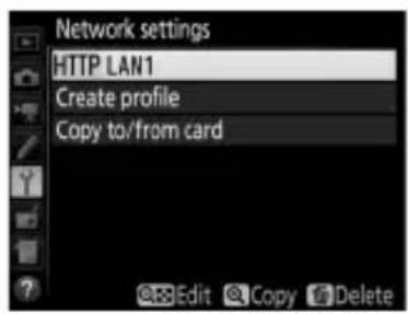
1 Display network profiles.
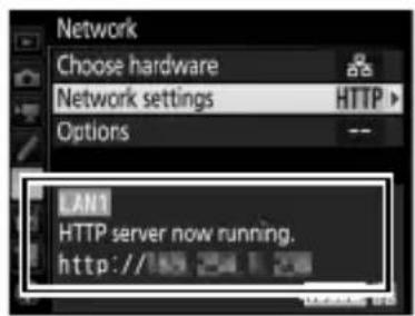
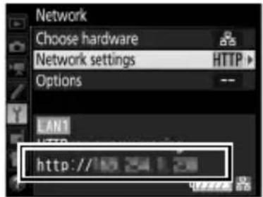
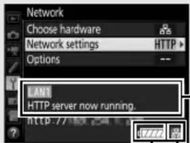
In the setup menu, select Network > Network settings to display the profiles list. HTTP server profiles are indicated by a HTTP icon. Highlight a profile and press Ⓞ to select the highlighted profile and return to the network menu.
The URL used for connection to the camera is displayed when a connection is established.
2 Launch the web browser.
Launch the web browser on the computer or smart device.
3 Enter the camera URL.
Enter the camera URL ("http://" followed by the camera IP address, as shown in the network menu) in the browser window address field.
HTTP Server

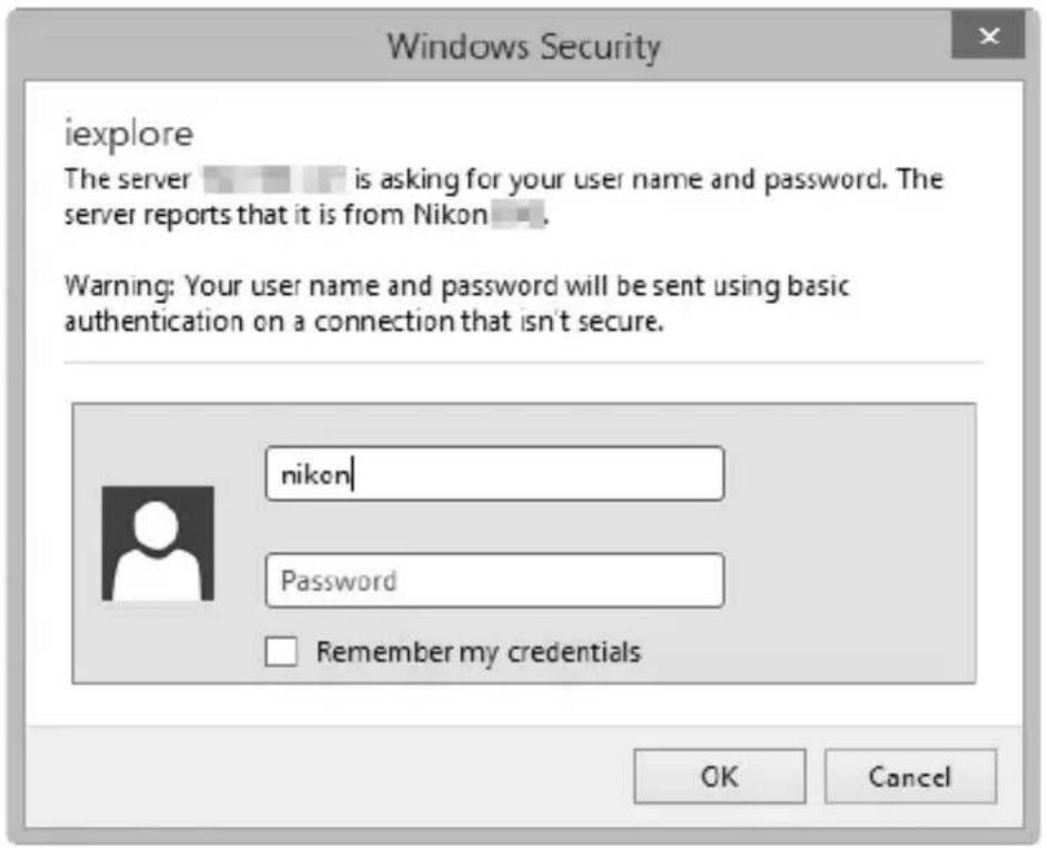
4 Log in.
Enter your user name and password in the web browser login dialog (the user name and password are set using Network settings > Options > HTTP user settings in the network menu as described on page 91; the default user name is "nikon" while the default password is blank).
5 Choose a language.
Click Language.
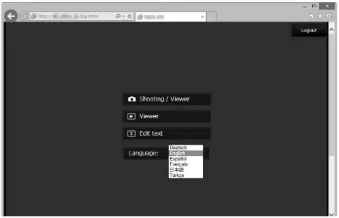
6 Choose an operating mode.
Choose Shooting/Viewer to take pictures (46, 53) and Shooting/Viewer or Viewer to view existing pictures (48, 55). To use the computer or smart device web browser to edit image comments and copyright and IPTC information stored on the camera, select Edit text (50, 57). Up to five users at a time can connect using Viewer, but only one user at a time can connect using Shooting/Viewer or Edit text (if another user is already connected using Shooting/Viewer or Edit text, these options will not be displayed and only four users will be able to connect using Viewer).

Network Status
The status of the link between the host and the WT-7 is shown by the status LEDs and by the display in the top level of the network menu.
The Status LEDs
The POWER LED lights when the WT-7 is on. Signal quality is shown by the LINK LED: the faster the LED flashes, the better the signal and the faster data can be transmitted. The ERROR LED flashes to show that an error has occurred.
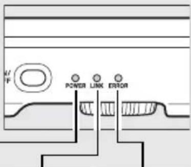
| Status POWER LINK ERROR | |||
| WT-7 off | ● (off) | ● (off) | ● (off) |
| USB cable not connected | ○ (on) | ● (off) | ● (off) |
| HTTP server starting up | ○ (on) | ○ (on) | ● (off) |
| HTTP server in operation | ○ (on) | ☀ (flashes) | ● (off) |
| Connection error | ○ (on) | ● (off) | ☀ (flashes) |
| WT-7 hardware or battery malfunction | ☀ (flashes) | ☀ (flashes) | ☀ (flashes) |
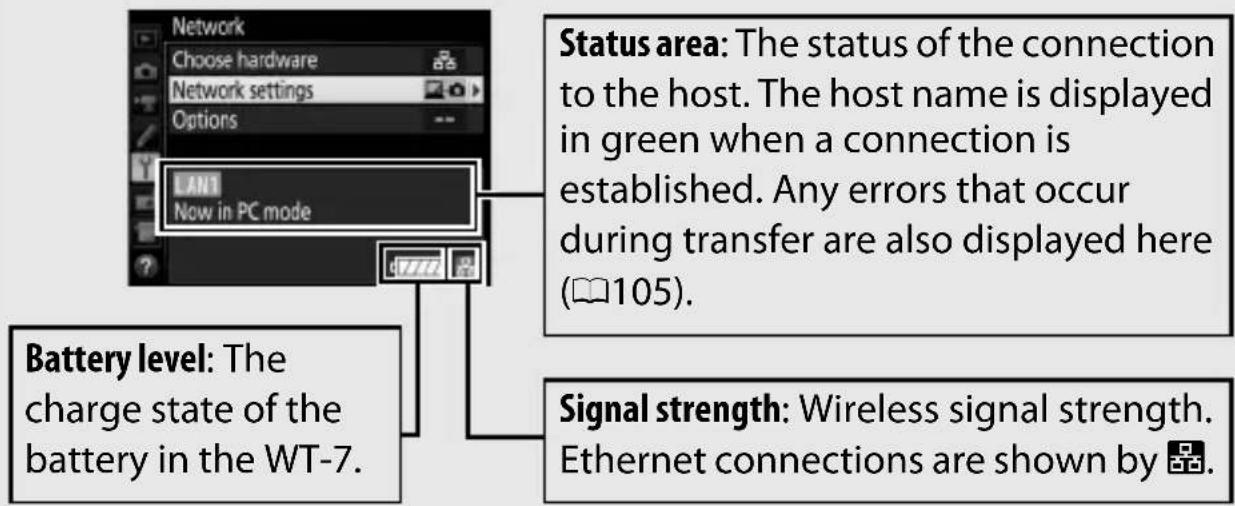
The Status Display
Network status can be viewed in the top level of the network menu.
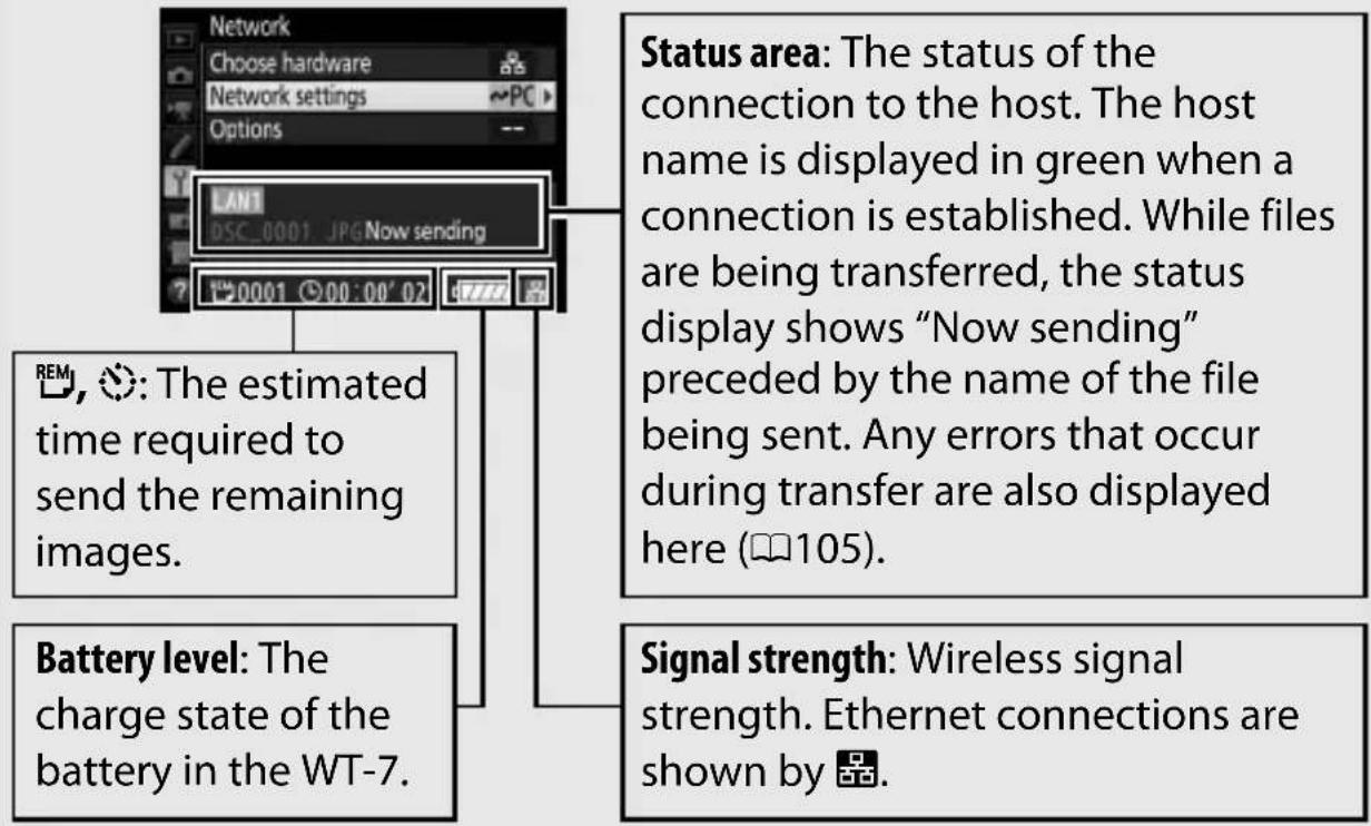
Status area: The status of the connection to the host. The camera URL is displayed in green when a connection is established. Errors are also displayed here (105).
Battery level: The charge state of the battery in the WT-7.
Signal strength: Wireless signal strength. Ethernet connections are shown by 📁.

HTTP Server System Requirements
Operation has been confirmed with the following systems:
| Windows | |
| OS Windows 10, Windows 8.1, Windows 7 | |
| Browser | •Windows 10: Microsoft Edge•Windows 8.1: Internet Explorer 11•Windows 7: Internet Explorer 10 |
| Monitor | •Resolution: 1,024 × 768 pixels (XGA) or more; 1,280 × 1,024 pixels (SXGA) or more recommended•Color: 24-bit color (True Color) or more |
| Mac | |
| OS OS X version 10.11, 10.10, or 10.9 | |
| Browser | •OS X version 10.11: Safari 9•OS X version 10.10: Safari 8•OS X version 10.9: Safari 7 |
| Monitor | •Resolution: 1,024 × 768 pixels (XGA) or more; 1,280 × 1,024 pixels (SXGA) or more recommended•Color: 24-bit color (millions of colors) or more |
| Android OS | |
| OS Android 5.0, 4.4 | |
| Browser Chrome | |
| iOS | |
| OS iOS 9, iOS 8 | |
| Browser The version of Safari included with the operating system |
Computer and Android Web Browsers
This section describes the http server displays for computer and Android web browsers (note that the display varies with the model of camera). Click or tap to adjust camera settings. For information on the displays for iPhones, see page 53.
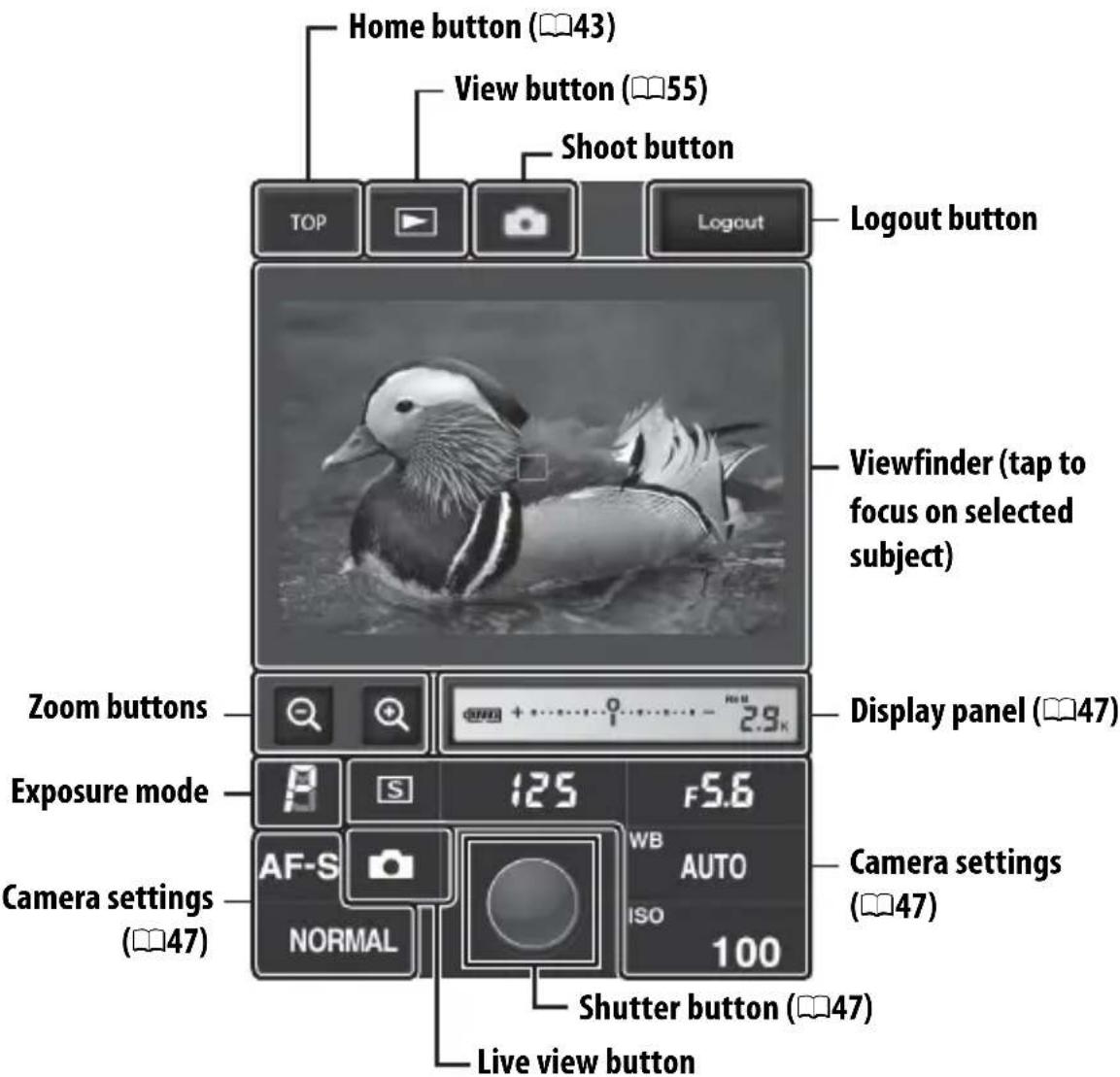
The Shooting Window
The following controls can be accessed by selecting Shooting/Viewer on the server home page. To display the view through the camera lens in the viewfinder area, tap or click the live view button. Tap or click the button again to exit live view.
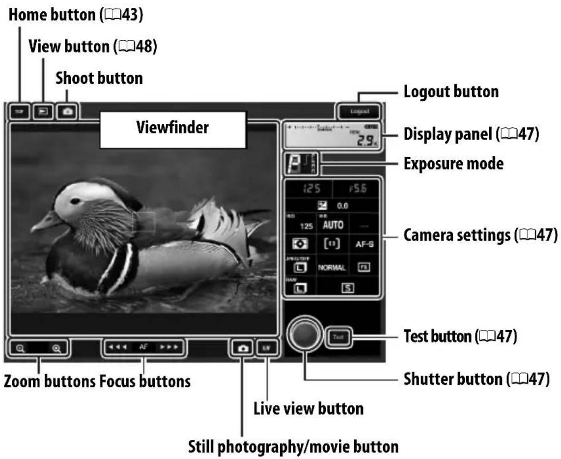

Focus Buttons
The size of the focus adjustment increases with the distance of the button from the center of the display.
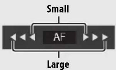
flowchart
graph TD
    A["Small"] --> B["AF"]
    B --> C["Large"]
    C --> D["Output"]
    style B fill:#000,stroke:#000,color:#fff
    style C fill:#000,stroke:#000,color:#fff
    style D fill:#000,stroke:#000,color:#fff
| Display panel | Contains the exposure indicator and shows the battery level and number of exposures remaining. |
| Camera settings | Click or tap icons to adjust settings for photography or movie recording. See the camera manual for details. |
| Shutter button | Take a photograph or start and end movie recording. To focus, click or tap the desired subject in the viewfinder area. |
| Test button | Take a test photo and display it in the viewfinder without recording it to the camera memory card. Not available in movie live view. |

Enabling Live View on the Camera
When the view through the camera lens is displayed in the viewfinder area, pressing the camera ☐ button will display the view through the lens in the camera monitor. Press the button again to end live view on the camera.

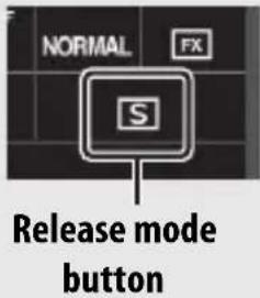
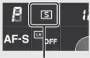
The Release Mode Button
Clicking or tapping the live view button enables the release mode button, which can be used to choose from single-frame, high-speed continuous, and low-speed continuous release modes. In high- and low-speed continuous release modes, the camera takes photographs while the shutter button is pressed.
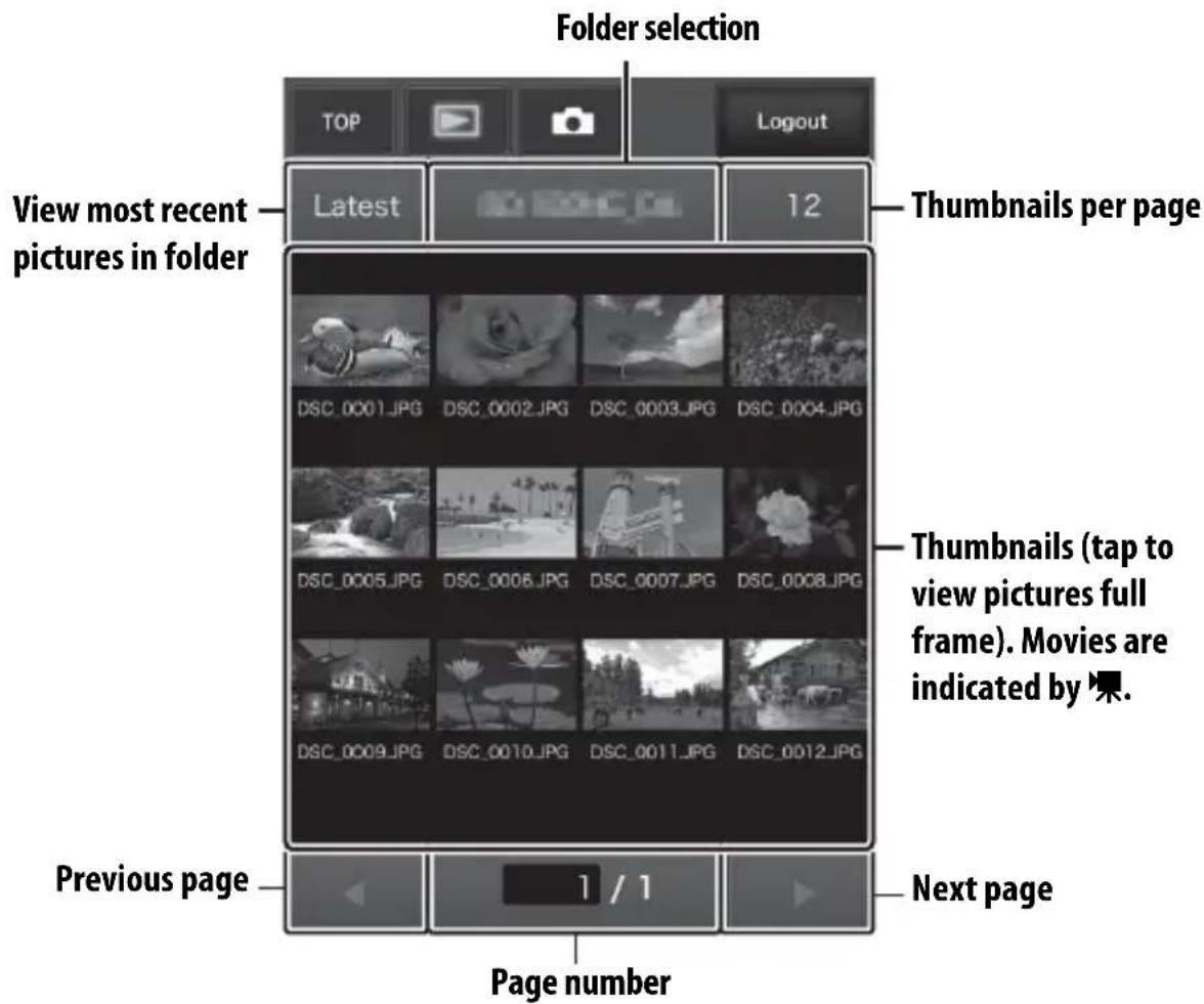
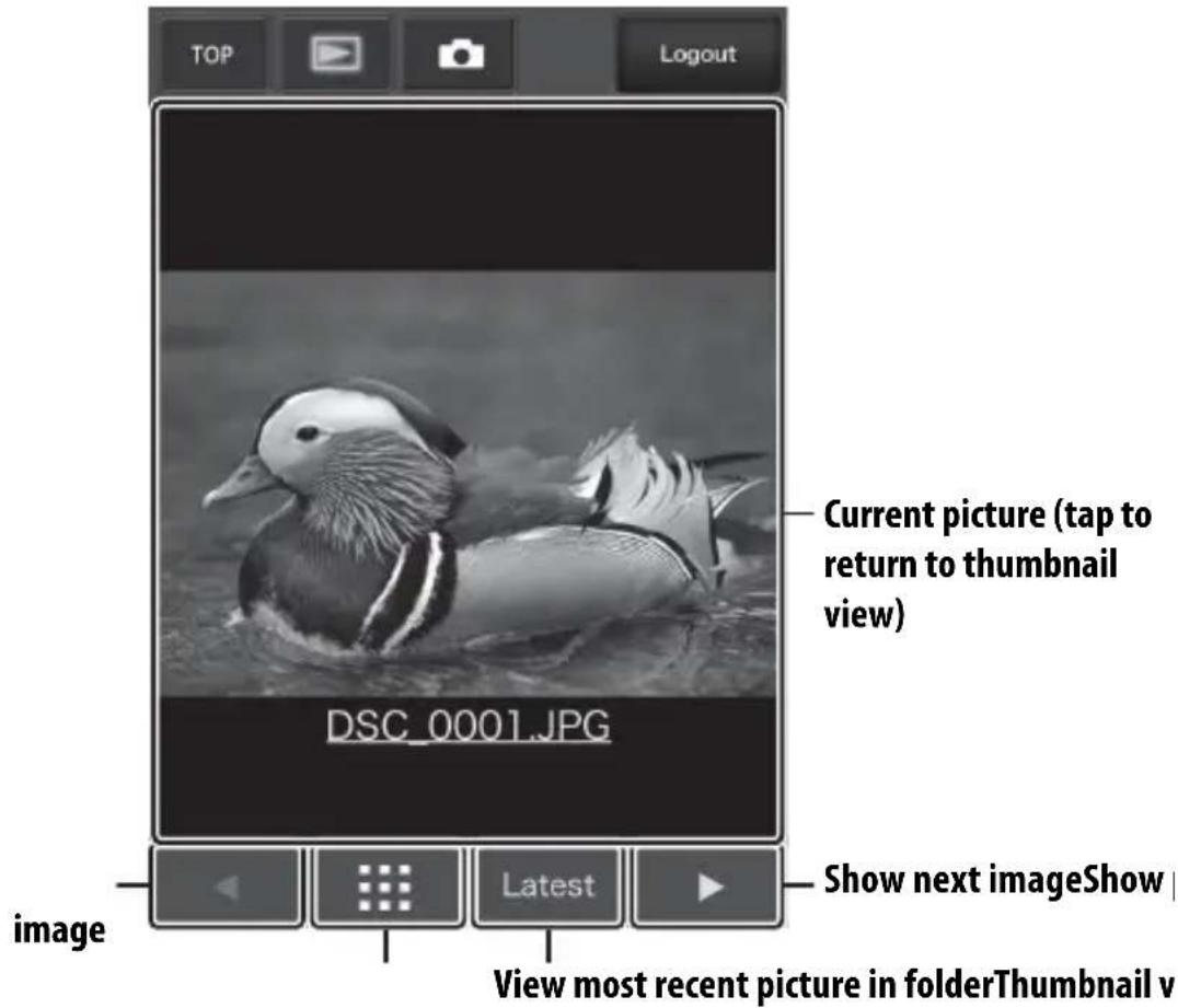
The Viewer Window
The viewer window can be accessed by selecting Viewer on the server home page or clicking or tapping the view button in the shooting window. The viewer window offers a choice of thumbnail, film-strip (49), and full-frame views (49).
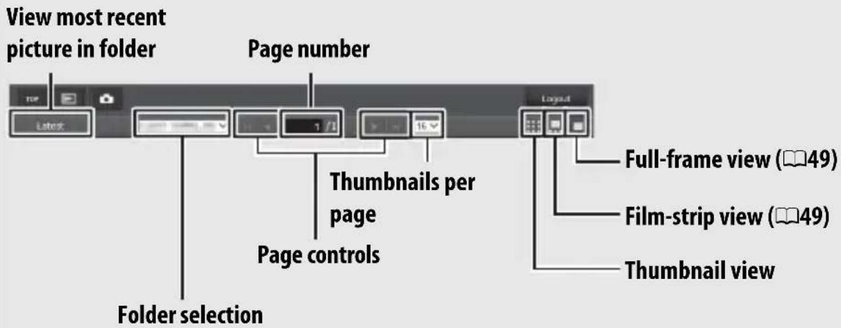
■Thumbnail View
View multiple small ("thumbnail") images per page. The controls at the top of the window can be used for navigation.
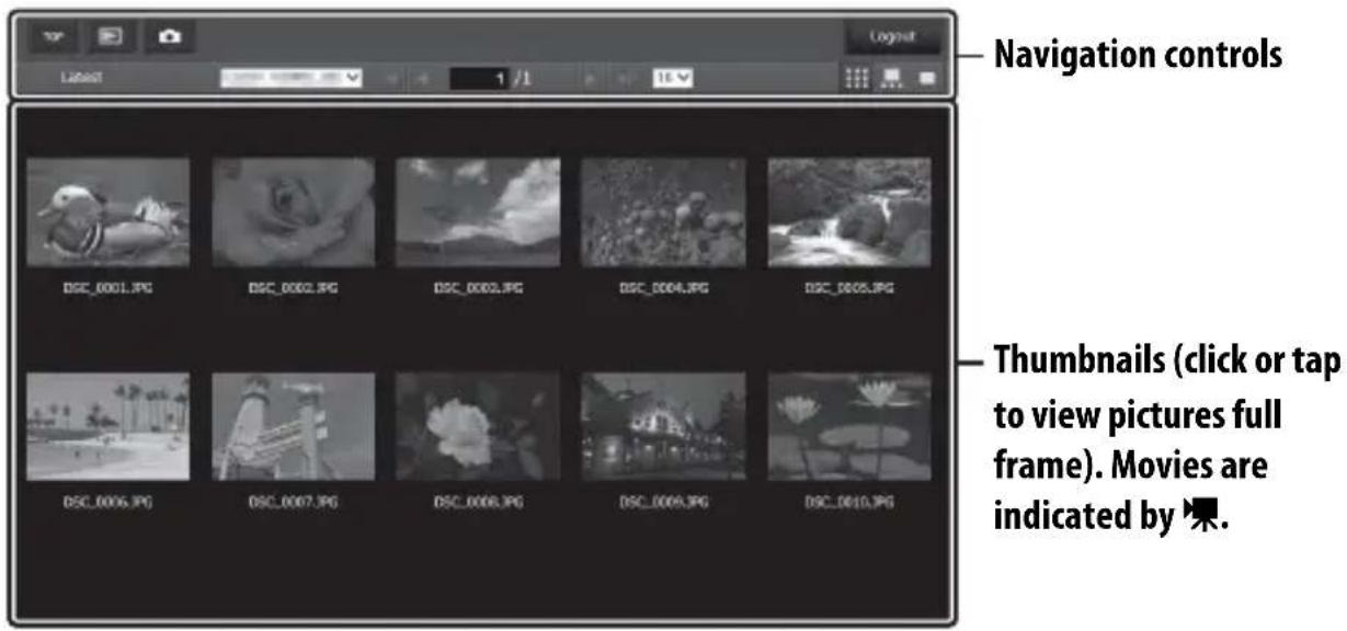

Navigation Controls
Film-Strip View
Choose the picture displayed from the thumbnails at the bottom of the window.
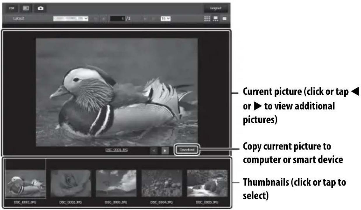
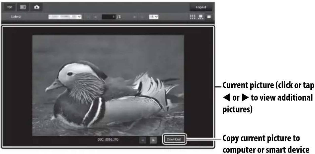
Full-Frame View
View pictures full frame.
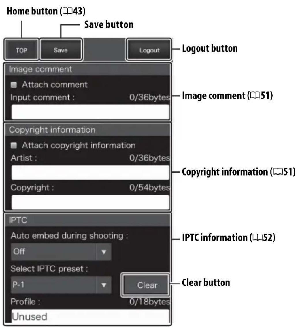
The Text Edit Window
The text edit window, which is used to edit image comments and copyright and IPTC information stored on the camera, can be accessed by selecting Edit text on the server home page.
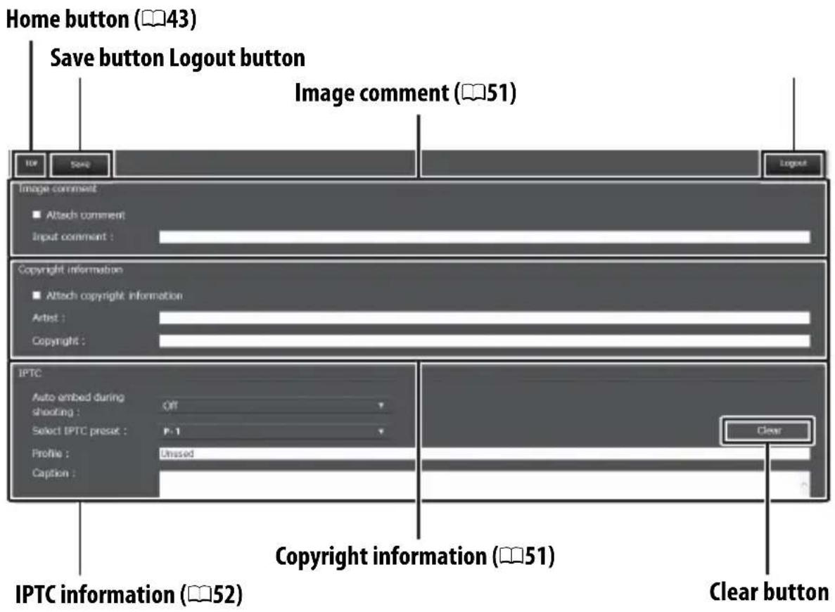
Saving Changes
Changes are not saved automatically. Click or tap the save button to save changes.
The Clear Button
Clicking or tapping the clear button immediately deletes the displayed text, even if you exit without clicking the save button.
Image Comment
Create a comment that can be appended to subsequent images. Comments can be viewed as metadata in ViewNX-i or Capture NX-D. The following options are available:
- Attach comment: Select this option to attach the comment to all subsequent photographs.
- Input comment: Input a comment up to 36 characters long.
Copyright Information
Add copyright information to new photographs as they are taken. Copyright information can be viewed as metadata in ViewNX-i or in Capture NX-D. The following options are available:
- Attach copyright information: Select this option to attach copyright information to all subsequent photographs.
- Artist/copyright: Enter a photographer name up to 36 characters long and a copyright holder name up to 54 characters long.
Viewing Image Comments and Copyright Information on the Camera
Image comments and copyright information can be viewed during full-frame playback on the corresponding pages of the camera photo information display.
Copyright Information
To prevent unauthorized use of the artist or copyright holder names, make sure that Attach copyright information is not selected and that the Artist and Copyright fields are blank before lending or transferring the camera to another person. Nikon does not accept liability for any damages or disputes arising from the use of the Copyright information option.
IPTC Information
Embed IPTC presets in photographs as they are taken. The following options are available:
- Auto embed during shooting: Selecting this tab displays a list of IPTC presets; highlight a preset and press the save button to embed the selected preset in all subsequent photographs. Select Off to take photos with no IPTC presets.
- Select IPTC preset: Selecting this tab displays a list of IPTC presets. Choose a preset to copy to the camera.
IPTC Information
IPTC is a standard established by the International Press Telecommunications Council (IPTC) with the intent of clarifying and simplifying the information required when photographs are shared with a variety of publications. Embedded IPTC information can be viewed by selecting the IPTC page in the photo information display during full-frame playback. See the camera manual for more information.
iPhone Web Browsers
This section describes the http server displays for iPhone web browsers (note that the display varies with the model of camera). Tap to adjust camera settings. For information on computer, Android, or iPad displays, see page 46.
The Shooting Window
The following controls can be accessed by selecting Shooting/Viewer on the server home page. Use the live view button to start live view photography (☐) or movie live view (☐). The view through the camera lens will be displayed in the viewfinder area. To exit live view, use the live view button to turn live view off.
Enabling Live View on the Camera
When the view through the camera lens is displayed in the viewfinder area, pressing the camera Lv button will display the view through the lens in the camera monitor. Press the button again to end live view on the camera.
The Release Mode Button
Selecting photo (☐) or movie (☐) live view with the live view button enables the release mode button, which can be used to choose from single-frame, high-speed continuous, and low-speed continuous release modes. In high- and low-speed continuous release modes, the camera takes photographs while the shutter button is pressed.
Release mode button
The Viewer Window
The viewer window can be accessed by selecting Viewer on the server home page or tapping the view button in the shooting window. The viewer window for iPhone web browsers offers a choice of thumbnail and full-frame views (56).
■Thumbnail View
View multiple small ("thumbnail") images per page. The controls at the top and bottom of the thumbnail area can be used for navigation.
Full-Frame View
View pictures full frame.
The Text Edit Window
The text edit window, which is used to edit image comments and copyright and IPTC information stored on the camera, can be accessed by selecting Edit text on the server home page.
Saving Changes
Changes are not saved automatically. Tap the save button to save changes.
FTP
Ethernet Connections
Follow the steps below to connect to an ftp server via an Ethernet network. For information on wireless connections, see page 65.
FTP server
Step 1: Connect the camera, WT-7, and ftp server (59)
Step 2: Select Ethernet (60)
Step 3: Run the connection wizard (61)
Transfer pictures (78)
√Choosing a Power Source
To prevent the camera or WT-7 powering off unexpectedly during setup or data transfer, use fully-charged batteries or optional AC adapters designated for use with the camera or WT-7. For more on camera power sources, see the camera manual.
FTP Servers
Servers can be configured using standard ftp services, such as IIS (Internet Information Services), available with supported operating systems (95). Connection to computers on other networks via a router, Internet ftp connections and ftp servers running third-party software are not supported.
Step 1: Connecting the Hardware
After starting the ftp server, connect the camera as described below.
1 Insert a memory card.
Turn the camera off and insert a memory card (do not turn the camera off or disconnect the Ethernet cable while data are being transferred to the computer).
2 Attach the WT-7 (📖 5).
3 Connect an Ethernet cable.
Connect the camera to the ftp server as shown below. Do not use force or insert the connectors at an angle.
natural_image
Line drawing of a laptop connected to a DSLR camera via cable (no text or symbols)4 Turn the camera on.
Rotate the power switch to turn the camera on.
5 Press the power switch for about a second to turn the WT-7 on.
Power switch
Step 2: Configuring the Hardware for Ethernet Connections
Configure the WT-7 for use with Ethernet networks.
1 Select Choose hardware.
In the setup menu, select Network, then highlight Choose hardware and press ⬆. The menu offers a choice of Wired LAN and Wireless LAN.

2 Select Wired LAN.
Highlight Wired LAN and press Ⓞ to select the highlighted option and return to the network menu.

Step 3: The Connection Wizard
Follow the on-screen instructions to create a network profile.
1 Display network profiles.
In the network menu, highlight Network settings and press 🔒 to display the profiles list and other network settings.
2 Select Create profile.
Highlight Create profile and press 🔒. Note that if the list already contains nine profiles, you will need to delete an existing profile using the ⏻ (FORMAT) button before proceeding (85).

3 Start the connection wizard.
Highlight Connection wizard and press ⬆ to start the connection wizard.
4 Choose a connection type.
Highlight FTP upload and press OK.
5 Name the new network profile.
A default profile name will be displayed; to edit or change the name as described in the camera manual, press the center of the multi selector (if the camera is a touch-screen model, you can enter characters by tapping the letters on the on-screen keyboard). The profile name will appear in the Network > Network settings list in the camera setup menu. Press Ⓞ to proceed to the next step when entry is complete.
Profile name
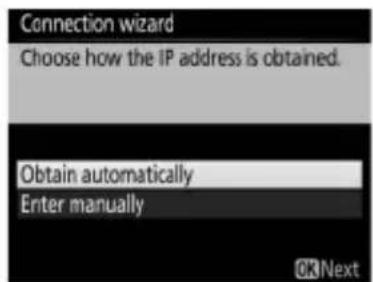
6 Obtain or select an IP address.
Highlight one of the following options and press Ⓞ.
- Obtain automatically: Select this option if the network is configured to supply the IP address automatically.
- Enter manually: When prompted, enter an IP address and subnet mask by pressing 🔒 and ➕ to highlight segments and 🔊 and ➤ to change. Press Ⓞ to proceed when entry is complete.
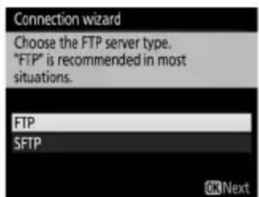
7 Choose the server type.
Highlight FTP or SFTP (secure ftp) and press 🔒.
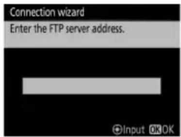
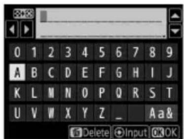
8 Enter the IP address.
Press the center of the multi selector and enter the server URL or IP address as described in the camera manual (if the camera is a touch-screen model, you can enter characters by tapping the letters on the on-screen keyboard).
Press Ⓞ when entry is complete.
Press Ⓞ again to connect to the ftp server.

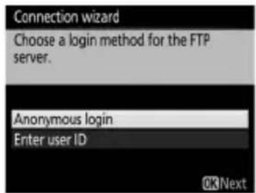
9 Log in.
Highlight one of the following options and press Ⓞ.
- Anonymous login: Select this option if the server does not require a user ID or password.
- Enter user ID: Enter a user ID and password when prompted and press Ⓞ.
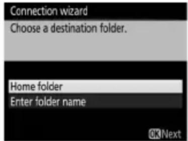
10 Choose a destination folder.
Highlight one of the following options and press Ⓞ.
- Home folder: Select this option to upload pictures to the server's home folder.
- Enter folder name: Select this option to upload pictures to another folder (the folder must already exist on the server). Enter a folder name and path when prompted and press Ⓞ.
11 Exit the wizard.
Highlight one of the following options and press Ⓞ.
- Connect and exit wizard: Save the new network profile and connect to the server.
- Exit wizard: Save the new network profile and exit.
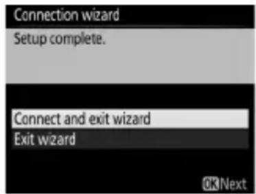
Proceed to "FTP Upload" (78).
Wireless Connections
Follow the steps below to connect to a wireless network.
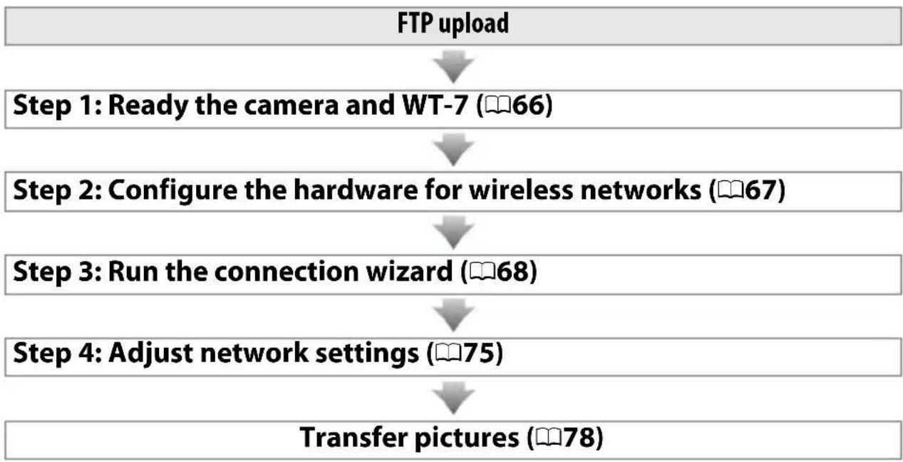
flowchart
graph TD
    A["FTP upload"] --> B["Step 1: Ready the camera and WT-7 (66)"]
    B --> C["Step 2: Configure the hardware for wireless networks (67)"]
    C --> D["Step 3: Run the connection wizard (68)"]
    D --> E["Step 4: Adjust network settings (75)"]
    E --> F["Transfer pictures (78)"]
Infrastructure and Access Point Modes
Connections to wireless networks may be in infrastructure or access point mode.
Infrastructure mode: Connection via a wireless LAN access point.
flowchart
graph LR
    A["Printer"] <--> B["Mobile Device"]
    B <--> C["Laptop"]
WT-7 Wireless LAN access point Computer
Access point mode: The camera serves as an access point for direct connection to a computer.
flowchart
graph LR
    A["WT-7 Computer"] <--> B["Laptop"]
Wireless LANs
These instructions are intended for customers with an existing wireless LAN, and in the case of infrastructure networks assume that the computer and access point are already connected to the network.
Step 1: Connecting the Equipment
After starting the computer and logging in, ready the camera and WT-7 as described below.
1 Insert a memory card.
Turn the camera off and insert a memory card (do not turn the camera off while data are being transferred to the computer).
2 Attach the WT-7 (5).
3 Turn the camera on.
Rotate the power switch to turn the camera on.
4 Press the power switch for about a second to turn on the WT-7.
Power switch
Step 2: Enable Camera Wireless
Ready the camera for connection to a wireless network.
1 Select Choose hardware.
In the setup menu, select Network, then highlight Choose hardware and press ⬆. The menu offers a choice of Wired LAN and Wireless LAN.
2 Select Wireless LAN.
Highlight Wireless LAN and press Ⓞ to select the highlighted option and return to the network menu.

Step 3: The Connection Wizard
Follow the on-screen instructions to create a network profile.
1 Display network profiles.
In the network menu, highlight Network settings and press ⬆ to display the profiles list and other network settings.
2 Select Create profile.
Highlight Create profile and press ⬤. Note that if the list already contains nine profiles, you will need to delete an existing profile using the Ⓞ(FORMAT) button before proceeding.
3 Start the connection wizard.
Highlight Connection wizard and press ⬆ to start the connection wizard.
4 Choose FTP upload (8).
Highlight FTP upload and press OK.
5 Name the new network profile.
A default profile name will be displayed; to edit or change the name as described in the camera manual, press the center of the multi selector (if the camera is a touch-screen model, you can enter characters by tapping the letters on the on-screen keyboard). The profile name will appear in the Network > Network settings list in the camera setup menu. Press Ⓞ to proceed to the next step when entry is complete.
6 Choose a connection method.
Highlight the connection method used by the network and press Ⓞ. More information can be found on the pages listed below.
| Search for wireless network | Choose from a list of networks detected by the camera. Proceed to page 70. |
| Push-button WPS | Choose for wireless LAN access points with push-button WPS. Proceed to page 72. |
| PIN-entry WPS | Choose for wireless LAN access points with PIN-entry WPS. Proceed to page 73. |
| Direct (access point) | Connect directly to a host computer or ftp server in access point mode, with the camera serving as an access point. Proceed to page 74. |
■Search for Wireless Network
Select Search for wireless network in Step 6 on page 69 to choose from a list of the networks (wireless LAN access points) detected by the camera.
1 Choose a network.
Highlight a network SSID and press Ⓧ (if the desired network is not displayed, press Ⓧ to search again). Encrypted networks are indicated by a 🔒 icon; if the selected network is encrypted, you will be prompted to enter the encryption key as described in Step 2. If the network is not encrypted, proceed to Step 3.
Hidden SSIDs
Networks with hidden SSIDs are indicated by blank entries in the network list. If you highlight a blank entry and press Ⓞ, you will be prompted to provide the network name; press the center of the multi selector, enter a name, and then press Ⓞ to proceed to Step 2.

2 Enter the encryption key.
Press the center of the multi selector and enter the encryption key as described in the camera manual (if the camera is a touch-screen model, you can enter characters by tapping the letters on the on-screen keyboard).
Press Ⓞ when entry is complete.

Press Ⓞ to establish a connection.
3 Choose your next step.
The message at right is displayed when a connection is established. Proceed to page 75.
■Push-Button WPS
Choose Push-button
WPS in Step 6 on page 69 if the wireless LAN access point uses push-button WPS.


1 Press the WPS button on the wireless LAN access point.
For more information, see the documentation provided with the wireless LAN access point.
2 Press Ⓞ button on the camera.
The camera will connect to the access point automatically.
3 Choose your next step.
The message at right is displayed when a connection is established. Proceed to page 75.

PIN-Entry WPS
Choose PIN-entry WPS in Step 6 on page 69 if the wireless LAN access point uses PIN-entry WPS.
1 Enter the PIN for the wireless LAN access point.
From a computer, enter the PIN for the wireless LAN access point. For more information, see the documentation provided with the wireless LAN access point.
2 Press Ⓞ button on the camera.
The camera will connect to the access point automatically.

3 Choose your next step.
The message at right is displayed when a connection is established. Proceed to page 75.

■Direct (Access Point)
Selecting Direct (access point) in Step 6 on page 69 enables access point mode, in which the camera serves as a wireless access point. The camera SSID and encryption key will be displayed in the monitor. On the computer or smart device, enter the SSID and encryption key displayed in the camera monitor (for more information, see the documentation provided with the computer or smart device). Proceed to Step 2 on page 75.

Step 4: Network Settings
Follow the steps below to connect to the ftp server. Skip Step 1 if you selected Direct (access point) in Step 6 on page 69.
1 Obtain or select an IP address.
Highlight one of the following options and press ⓄK.
- Obtain automatically: Select this option if the network is configured to supply the IP address automatically. The camera
will display the IP address provided by the network; press Ⓞ to proceed.
- Enter manually: When prompted, enter an IP address and subnet mask by pressing 🔒 and ▶ to highlight segments and ⬆ and ▽ to change. Press OK when entry is complete. The camera will display the selected IP address; press OK to proceed.
2 Choose the server type.
Highlight FTP or SFTP (secure ftp) and press Ⓞ. If you selected Direct (access point) in Step 6 on page 69, proceed to Step 4.
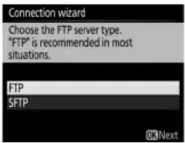
3 Enter the IP address.
Press the center of the multi selector and enter the server URL or IP address as described in the camera manual (if the camera is a touch-screen model, you can enter characters by tapping the letters on the on-screen keyboard).
Press Ⓞ when entry is complete.

Press Ⓞ again to connect to the ftp server.

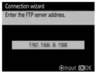
4 Log in.
Highlight one of the following options and press Ⓞ.
- Anonymous login: Select this option if the server does not require a user ID or password.
- Enter user ID: Enter a user ID and password when prompted and press Ⓞ.
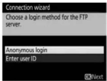
MAC Address Filtering
If the network uses MAC address filtering, the filter must be supplied with the MAC address of the WT-7. After attaching the WT-7 to the camera, choose Network > Options > MAC address from the camera setup menu and note the MAC address.
5 Choose a destination folder.
Highlight one of the following options and press ⓄK.
- Home folder: Select this option to upload pictures to the server's home folder.
- Enter folder name: Select this option to upload pictures to another of the folders existing on the server. Enter a folder name and path when prompted and press Ⓞ.
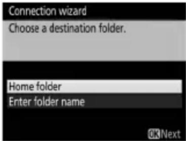
6 Exit the wizard.
Highlight one of the following options and press Ⓞ.
- Connect and exit wizard: Save the new network profile and connect to the server.
- Exit wizard: Save the new network profile and exit.
Proceed to "FTP Upload" (78).
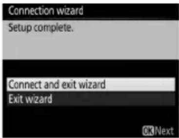
FTP Upload
Photos and movies can be uploaded from camera memory cards to an ftp server as described below, or photos can be uploaded as they are taken. For information on setting up an ftp server, see page 95.
1 Display network profiles.
In the setup menu, select Network > Network settings to display the profiles list. FTP server profiles are indicated by a \~FTP icon. Highlight a profile and press ⏻ to select the highlighted profile and return to the network menu.
The profile name will be displayed in green when a connection is established.
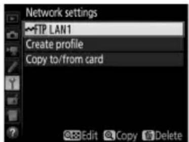
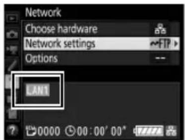
2 View pictures.
Press the ▶ button to view pictures. Display the first picture to be sent full frame or highlight it in the thumbnail list.

natural_image
Illustration of a woman with shoulder-length hair, standing by the sea with a sailboat and mountains in the background (no text or symbols)FTP upload
3 Upload pictures.
Press Ⓞ and the center of the multi selector. A white transfer icon will appear on the picture and upload will begin immediately. The transfer icon turns green during upload, and turns blue when upload is complete. Additional pictures will be uploaded in the order selected.

natural_image
Illustration of a woman in a boat on water with a sailboat and mountains in the background (no text or symbols)To upload a picture that has already been uploaded once, press Ⓞ and the center of the multi selector once to remove the blue transfer icon, and then press Ⓞ and the center of the multi selector again to mark the image with a white transfer icon.

natural_image
Illustration of a woman with hands clasped, standing by the sea with a sailboat and mountains in the background (no text or symbols)Uploading New Photographs as They Are Taken
To upload new photographs as they are taken, select On for Network > Options > Auto send in the setup menu (89).
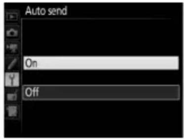
Interrupting Transmission/Removing Transfer Marking
To cancel transmission of images marked with white or green transfer icons, select the images during playback and press Ⓞ and the center of the multi selector. The transfer icon will be removed. Any of the following actions will also interrupt transmission:
- Turning the camera off
- Selecting Yes for Network > Options > Deselect all? (91; this option also removes transfer marking from all images)
During Upload
Do not remove the memory card or disconnect the Ethernet cable during upload.
Interval Timer Photography
Upload will be interrupted if the standby timer expires while interval timer photography is in progress. Choose a long standby time before starting the interval timer.
Loss of Signal
Wireless transmission may be interrupted if the signal is lost, but can be resumed by turning the camera off and then on again.
Turning the Camera Off
"Send" marking will be saved if the camera or WT-7 is turned off while transmission is in progress. Transmission of images marked with a "send" icon will resume when the camera or WT-7 is turned on.
Transfer Status
During playback, the status of images selected for upload is shown as follows:
: "Send"
Images that have been selected for upload are marked with a white 📋 icon.
: "Sending"
A green 📋 icon is displayed during upload.

natural_image
Illustration of a woman with hands clasped, standing by the sea with a sailboat and mountains in the background (no text or symbols)FTP upload
: "Sent"
Images that have been uploaded successfully are marked with a blue 🔊 icon.
Network Status
The status of the link between the host and the WT-7 is shown by the status LEDs and by the display in the top level of the network menu.
The Status LEDs
The POWER LED lights when the WT-7 is on. Signal quality is shown by the LINK LED: the faster the LED flashes, the better the signal and the faster data can be transmitted. The ERROR LED flashes to show that an error has occurred.
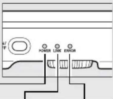
| Status POWER LINK ERROR | |||
| WT-7 off | ● (off) | ● (off) | ● (off) |
| USB cable not connected | ○ (on) | ● (off) | ● (off) |
| Connecting to host | ○ (on) | ○ (on) | ● (off) |
| Waiting to send or sending data | ○ (on) | flashes) | ● (off) |
| Connection error | ○ (on) | ● (off) | flashes) |
| WT-7 hardware or battery malfunction | flashes) | flashes) | flashes) |
The Status Display
Network status can also be viewed in the top level of the network menu.
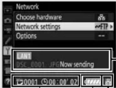
REM, ⚙: The estimated time required to send the remaining images.
Status area: The status of the connection to the host. The host name is displayed in green when a connection is established. While files are being transferred, the status display shows "Now sending" preceded by the name of the file being sent. Any errors that occur during transfer are also displayed here (105).
Battery level: The charge state of the battery in the WT-7.
Signal strength: Wireless signal strength. Ethernet connections are shown by 📁.
Menu Guide
This section describes the settings available for the Network option in the camera setup menu when the WT-7 is connected.

Choose Hardware
Choose the hardware used to connect to the network: Ethernet (Wired LAN) or wireless LAN (Wireless LAN).
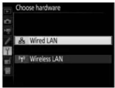
Network Settings
Highlight Network settings and press ⬆ to display the network profiles list, where you can create new profiles or select an existing profile.
The Profile List
The camera can store up to nine network profiles. Highlight a profile and press ➤ to connect to the highlighted host computer or ftp server, or press ⏻ (FORMAT) to delete the highlighted profile (85). To view information on the highlighted profile, press 📄 (✗/?).
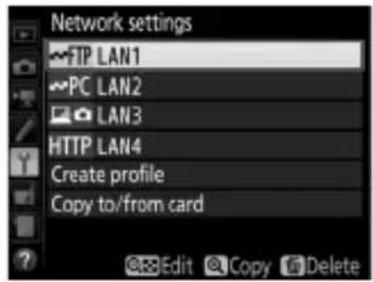
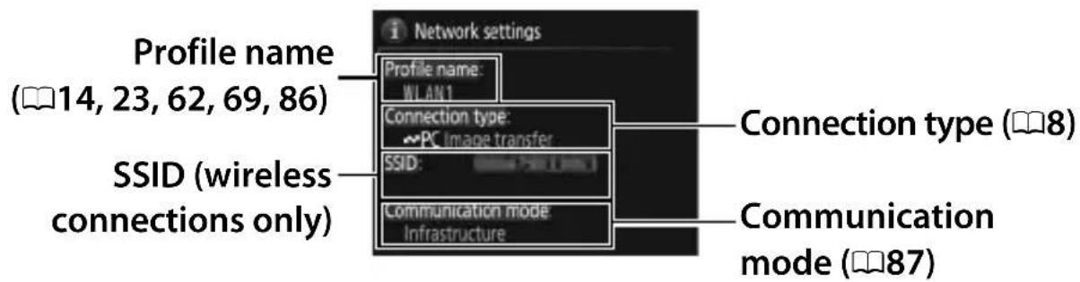
To edit the highlighted profile, press 🔒 (⚡) (☐86).
Create Profile
Choose Connection wizard to create network profiles with the help of a wizard (13, 22, 61, 68), Configure manually to enter ftp and http server settings manually (103).
Copy to/from Card
This option is available only with ftp and http server connections. Select Copy profile from card to copy profiles from the root directory of the memory card to the profile list. Selecting Copy profile to card displays the camera profile list; highlight a profile and press Ⓞ to copy the profile to the card (password-protected profiles can not be copied; ☐86). If there are two memory cards inserted in the camera, the card in the primary slot will be used for both “copy from” and “copy to” operations.
Deleting Network Profiles
Press ⏻ (FORMAT) to delete the profile currently highlighted in the profile list. A confirmation dialog will be displayed; highlight Yes and press OK.
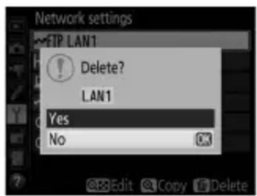
Editing Network Profiles
To edit network profiles, highlight the profile in the profile list, press Ⓞ (⚡), and choose from the following options:
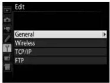
| General Edit the profile name and password. | |
| Wireless | Edit wireless settings (wireless connections only; 87). |
| TCP/IP | Edit TCP/IP settings (88). |
| FTP | Edit ftp settings (88). |
General
Choose Profile name to edit the profile name, Password protection to enter a profile password and enable or disable password protection. Enabling password protection prevents others from viewing network settings.
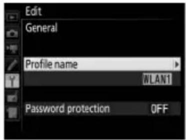
Editing Profiles
If the shutter-release button is pressed while menus are displayed, the monitor will turn off and any changes to the current profile will be lost.
Wireless
Edit the following wireless settings:
- SSID (required): Enter the name (SSID) of the network on which the host computer or ftp server is located.
- Communication mode: Select Infrastructure
for wireless communication via a wireless network access point, Access point to use the camera as an access point to connect to the ftp server or computer instead of connecting via a wireless network access point.
![Edit Wireless [1/2] SSID Communication mode Channel](/content/2026/05/816364/images/88b144ba414b1d956466c009f1568ccd129247e221d4460fdc834a66a84e9bcf.jpg)
- Channel: Select a channel (access point mode only; in infrastructure mode, the channel will be selected automatically).
- Authentication: The authentication used on the network. Choose from open system, shared key, WPA-PSK, and WPA2-PSK (infrastructure) or open system and WPA2-PSK (access point mode).
- Encryption: The encryption used on the network. The options available depend on the authentication used:
Open: None; 64- or 128-bit WEP available when Infrastructure is selected for Communication mode
Shared: 64- or 128-bit WEP
WPA-PSK: TKIP; AES
WPA2-PSK: AES
- Encryption key: If the network uses encryption, enter the network key. The number of characters required depends on the type of key used:
| WEP (64-bit) | WEP (128-bit) | TKIP, AES | |
| Number of characters (ASCII) 5 1 | 3 8–63 | ||
| Number of characters (hex) 10 | 26 64 |
- Key index: If WEP64 or WEP128 is selected for Encryption in infrastructure mode, choose a key index matching that used by the access point or host computer. A key index is not required when No encryption is selected.
TCP/IP
If the network is configured to supply IP addresses automatically, select Enable for Obtain automatically. Otherwise select Disable and enter the following information:
- Address/Mask: Enter an IP address and subnet mask.
- Gateway: If the network requires a gateway address, select Enable and enter the address supplied by the network administrator.
- Domain Name Server (DNS): If a Domain Name Server exists on the network, select Enable and enter the address supplied by the network administrator.
FTP
Edit the following ftp settings:
- Server type: Choose ftp or sftp and enter the URL or IP address (required), destination folder, and port number.
- PASV mode: Select Enable to enable PASV mode.
- Anonymous login: Select Enable for anonymous login, or select Disable to supply a User ID and Password.
- Proxy server: If a proxy server is required for ftp, select Enable and enter the address and port number for the proxy server.
![Edit TCP/IP [1/2] Obtain automatically OFF Address : 000 000 000 000 Mask : 000 000 000 000](/content/2026/05/816364/images/513a268200d5550007a4bf4941f5ef88257cdf36f1ef56bf19731eb6ffa3faeb.jpg)
![Edit FTP [1/3] Server type FTP Address : 100 100 100 Folder : Port : 24 PASV mode ON](/content/2026/05/816364/images/beef0705cfeb372805d89197a9dfa9429d7d956d8c59ba91bb609d4373a53438.jpg)
Options
Edit the following settings.
Auto Send
If On is selected for image transfer or ftp server connections, photos will automatically be uploaded to the computer or ftp server as they are taken (note, however, that photos can only be taken when a memory card is inserted in the camera). Movies can not be uploaded using this option; transfer movies during playback as described on pages 32 and 78.
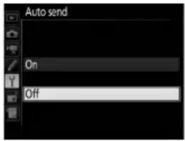
Options
Delete After Send
Select Yes to delete photographs from the camera memory card automatically once upload is complete (image transfer and ftp server connections only; files marked for transfer before this option is selected are unaffected). Regardless of the option selected for file number sequence in the camera Custom Settings menu, sequential number is used while this option is in effect, even if the folder changes or the memory card is replaced. Deletion may be suspended during some camera operations.
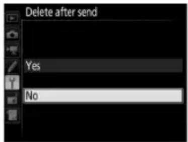
Send File As
When transferring NEF+JPEG images to a computer or ftp server (image transfer and ftp server connections only), choose whether to upload both the NEF (RAW) and JPEG files or only the JPEG copy.
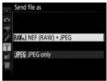
Overwrite If Same Name
Choose Yes to overwrite files with duplicate names during upload to an ftp server, No to add numbers to the names of newly uploaded files as necessary to prevent existing files being overwritten.
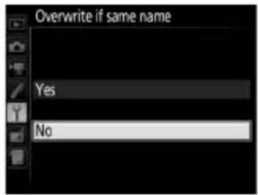
Protect If Marked for Upload
Select Yes to automatically protect files marked for upload to an ftp server. Protection is removed as the files are uploaded.
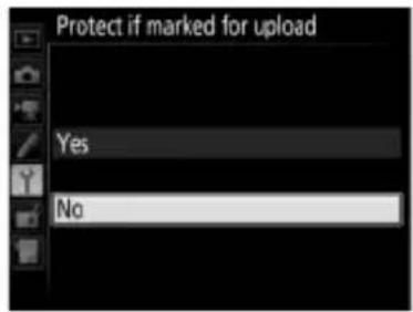
Send Marking (FTP Upload Mode Only)
Select On to add a timestamp to the pictures on the camera memory card giving the time of upload. The timestamp can be viewed using ViewNX-i or Capture NX-D. For more information, see online help for the software in question or the Capture NX-D manual.
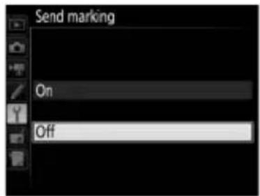
Send Folder
Select a folder for upload (image transfer and ftp server connections only). All photos in the selected folder (including those already marked as “sent”) will be uploaded, beginning immediately. Movies can not be uploaded using this option; transfer movies during playback as described on pages 32 and 78.
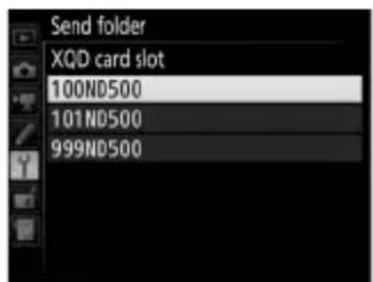
Deselect All?
Select Yes to remove transfer marking from all images selected for upload to a computer or ftp server (image transfer and ftp server connections only). Upload of images with a "sending" icon will immediately be terminated.

Options
HTTP User Settings
Enter a user name and password for connection to an http server (http server connections only).
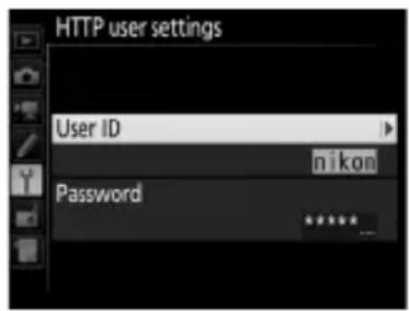
Battery Info
Display information for the battery inserted in the WT-7. The five-level Battery age display shows the battery age: 0 indicates that battery performance is unimpaired, 4 that the battery has reached the end of its charging life and requires replacement.
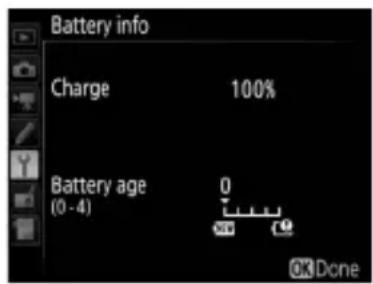
Power Saving
Choose Prioritize network speed for faster network speeds, Prioritize power saving for reduced power consumption. Prioritize network speed ensures that LAN connections remain active even when data are not being exchanged with the server and allows Ethernet connections using the high-speed 1000BASE-T standard. Prioritize power saving limits Ethernet connections to 100BASE-TX and ensures that LAN connections are terminated automatically when data transfer ends.
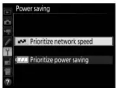
Auto Power off Delay
Choose how long the WT-7 remains on once the camera has turned off or the USB connection to the camera is terminated.
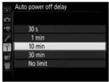
MAC Address
Display the MAC address of the hardware selected for Choose hardware (83).
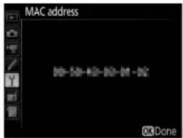
Firmware Version
View the current WT-7 firmware version.
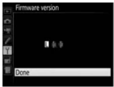
Appendices
Creating Profiles on a Computer
The Wireless Transmitter Utility (6) can be used to create network profiles.
1 Connect the camera.
Start the computer and connect the camera using the supplied USB cable.
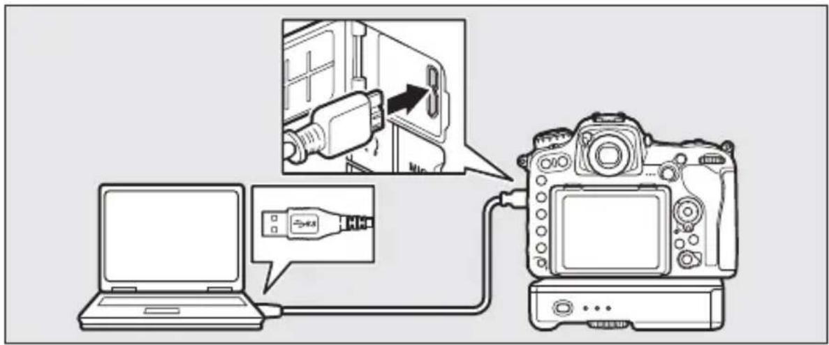
2 Turn the camera on.
Rotate the power switch to turn the camera on.
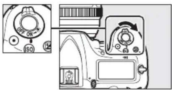
3 Start the Wireless Transmitter Utility.
Double-click the Wireless Transmitter Utility icon on the desktop (Windows) or click the Wireless Transmitter Utility icon in the Dock (Mac).
4 Create a profile.
Follow the on-screen instructions to create a network profile.
Creating an FTP Server
Images can be uploaded to ftp servers created using the standard ftp services included with Windows 10 (Enterprise/Pro/Home), Windows 8.1, Windows 8.1 (Enterprise/Pro), and Windows 7 (Professional/Enterprise/Ultimate). Under Windows, Internet Information Services (IIS) are required to configure ftp servers (installation instructions are available from Microsoft).
The following settings are used below for illustrative purposes:

IP address: 192.168.1.3
Subnet mask: 255.255.255.0
ftp server port: 21
1 Go to Network and Sharing Center.
Click Control Panel > Network and Internet > Network and Sharing Center.
2 Display the network adapter list.
Click Change adapter settings.
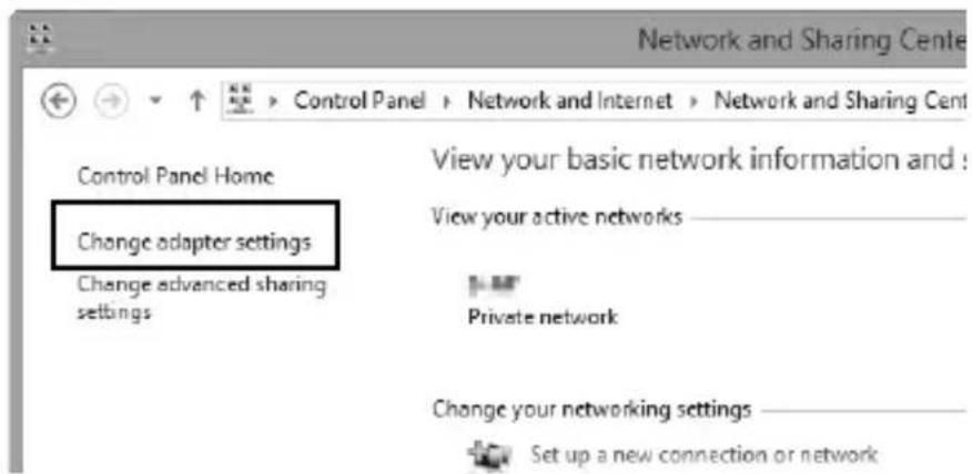
3 Open the network properties dialog.
If you are connecting via a wireless LAN adapter, right-click Wi-Fi (Windows 8.1) or Wireless Network Connection (Windows 7) and select Properties. If you are connecting via Ethernet, right-click Ethernet (Windows 8.1) or Local Area Connection (Windows 7) and select Properties.
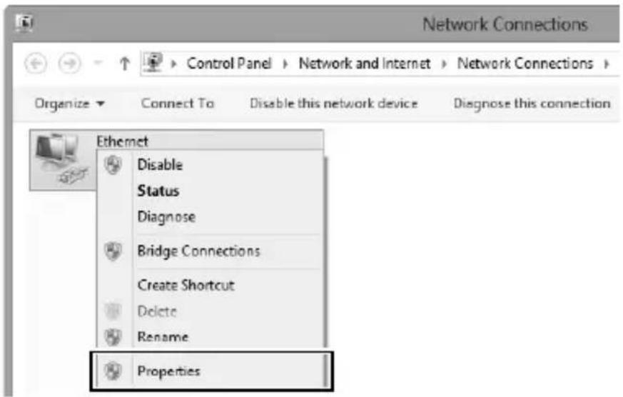
4 Display TCP/IP settings.
Select Internet Protocol Version 4 (TCP/IPv4) and click Properties.
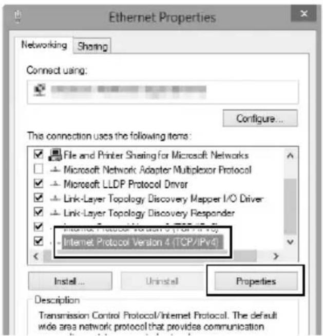
5 Enter an IP address and subnet mask.
Enter an IP address and subnet mask for the ftp server and click OK.
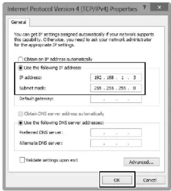
6 Close the network properties dialog. Click Close.
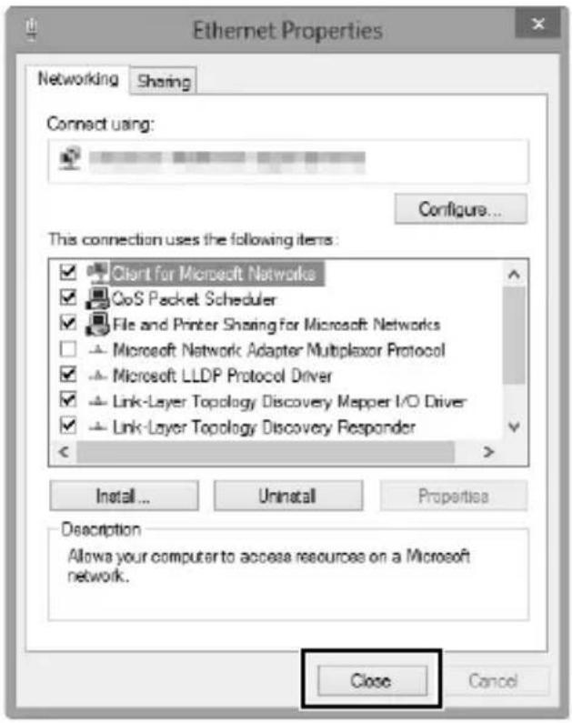
7 Open Administrative Tools.
Click Control Panel > System and Security > Administrative Tools.
8 Open the IIS manager.
Double-click Internet Information Services (IIS) Manager.
![Administrative Tools File Home Share View ► Control Panel ► System and Security ► Administrative Tools Favorites Desktop Downloads Recent places Libraries Documents Music Pictures Videos Homegroup Computer Windows B EN [C] Component Services Computer Management Defragment and Optimize Drives Disk Cleanup Event Viewer Internet Information Services (IIS) Manager Local Security Policy ODBC Data Sources Performance Monitor Print Management Resource Monitor Services System Configuration System Information Task Scheduler Windows Firewall with Advanced Security](/content/2026/05/816364/images/7614ec08a96b068285c94974ced5fdd307ed0d8f6a61fc9df05be33405b0f264.jpg)
9 Select Add FTP Site...
Right-click the computer user name and select Add FTP Site...
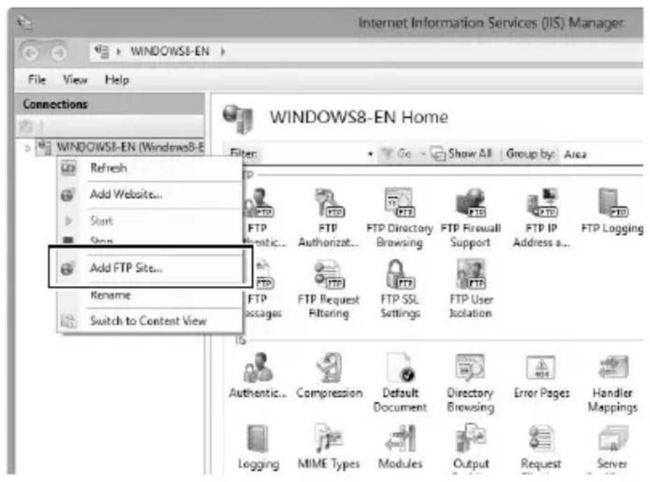
10 Enter site information.
Name the site and choose the path to the folder that will be used for ftp upload. Click Next to proceed.
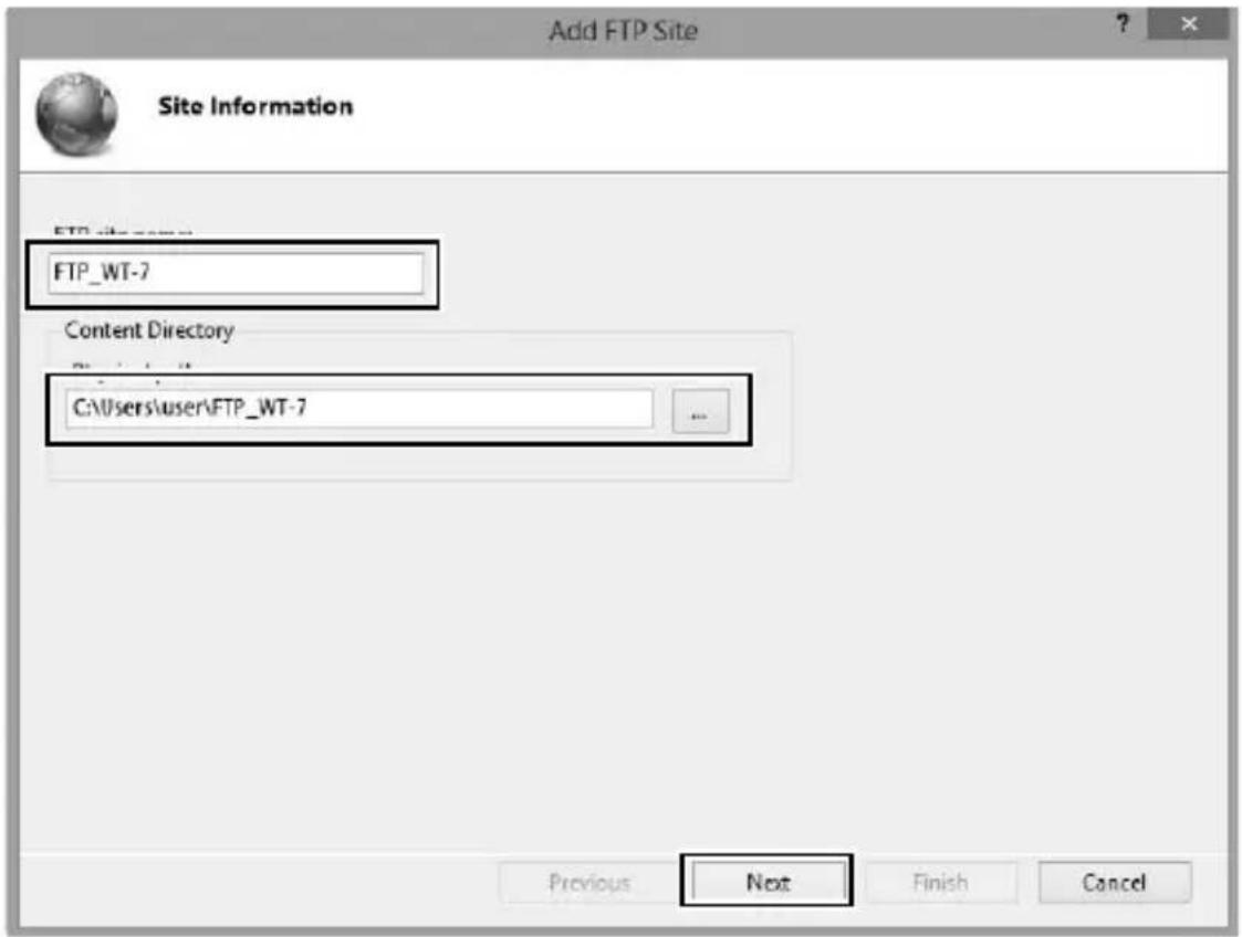
Anonymous Login
To allow anonymous login, select a folder in the user's public folder as the content directory.
11 Choose binding and SSL options.
Select the IP address entered in Step 5, note the port number, select Start FTP site automatically, and check No SSL. Click Next to proceed.
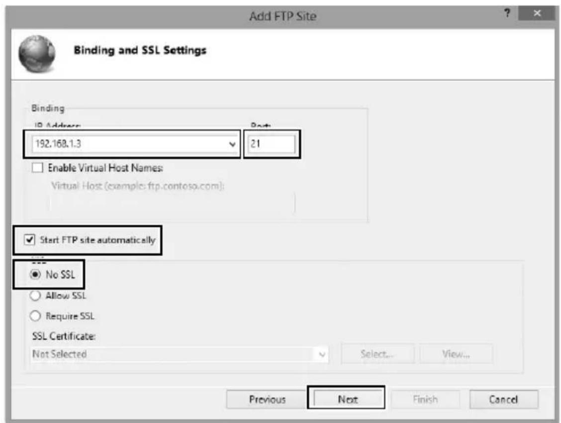
12 Choose authentication options.
Adjust settings as described below and click Finish.
- Authentication: Basic
- Allow access to: All users
- Permissions: Read/Write
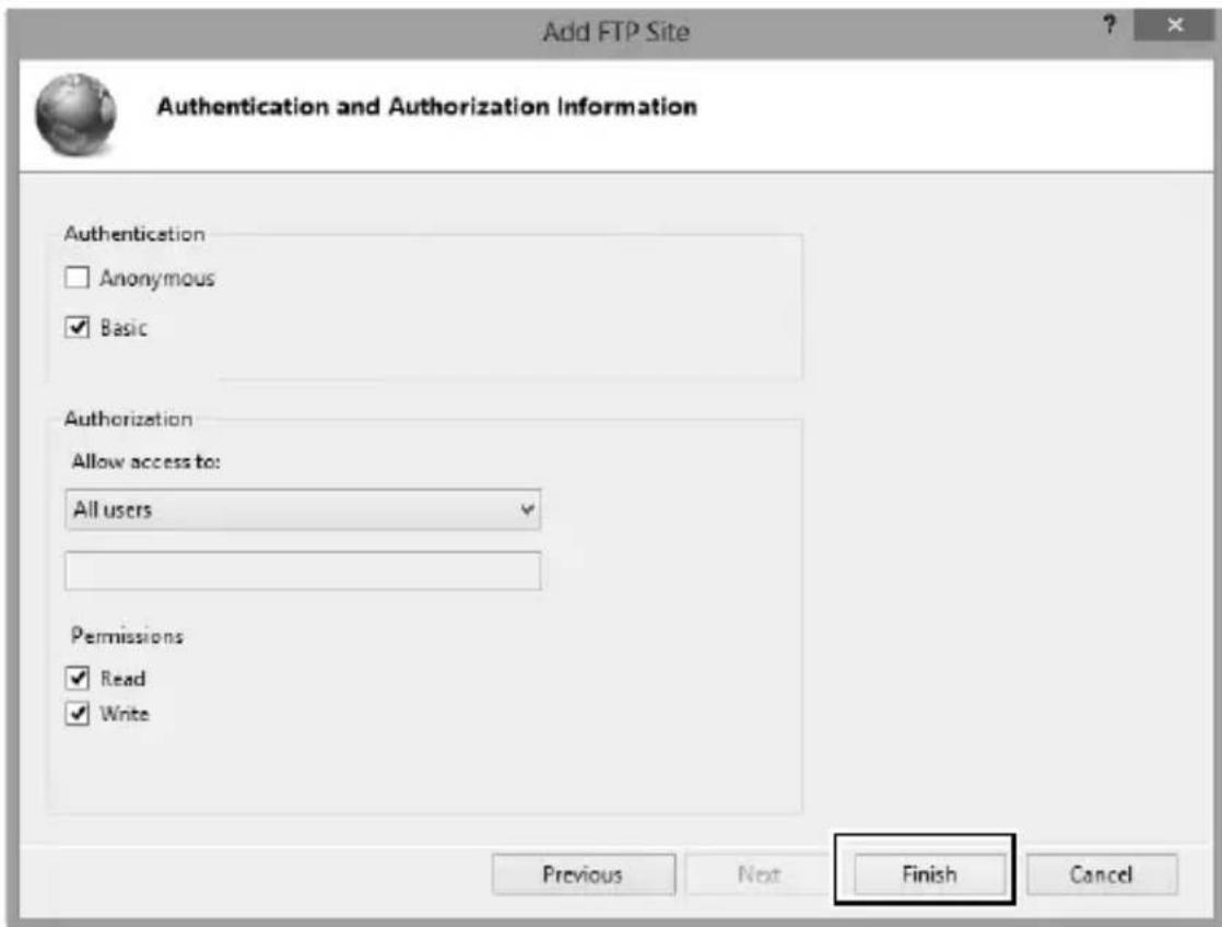
Manual Profile Creation
Follow the steps below to manually configure the camera for connection to ftp and http servers. Note that changes to the current profile will be lost if the camera is turned off during setup; to prevent unexpected loss of power, use fully-charged batteries or optional AC adapters designated for use with the camera and WT-7. If you are connecting to an ftp server behind a firewall, you may also need to adjust firewall settings to create exceptions for the ftp ports used by the camera (ports 21, 22, and 32768 through 61000).
1 Display network profiles.
In the network menu, highlight Network settings and press ⬆ to display the profiles list and other network settings.
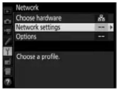
2 Select Create profile.
Highlight Create profile and press ⬇. Note that if the list already contains nine profiles, you will need to delete an existing profile using the ⏻ (FORMAT) button before proceeding (85).
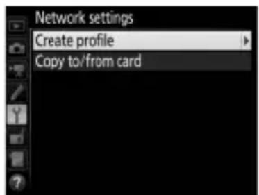
3 Select Configure manually.
Highlight Configure manually and press ⬆.
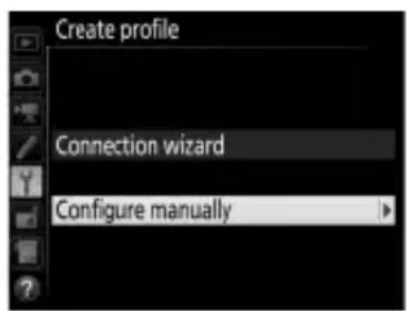
4 Select a connection type.
Highlight FTP upload or HTTP server and press ⬇.
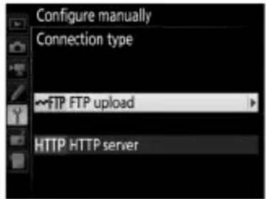
5 Adjust settings.
Adjust settings as described in "Editing Network Profiles" (86).
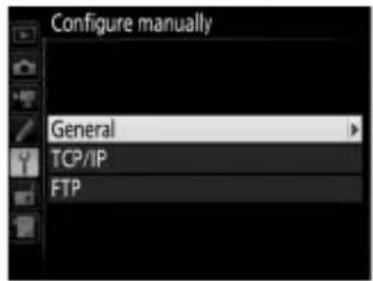
Editing Profiles
If the shutter-release button is pressed while menus are displayed, the monitor will turn off and any changes to the current profile will be lost. Choose a longer monitor off delay for Custom Setting in the camera menus.
Troubleshooting
| Problem Solution Page | ||
| "POWER" LED does not light. | Turn the WT-7 on.Confirm that the battery is inserted and fully charged. | 11, 20, 59, 664, 91 |
| Network option not available. | Confirm that the WT-7 is connected and on. | 11, 20, 59, 66 |
| Excessive radio interference. | Adjust the position of the wireless access point or host computer. | — |
| All LEDs flash at once. | WT-7 hardware or battery malfunction. Contact a Nikon-authorized service representative. | — |
| Camera displays TCP/IP or FTP error. | Check settings for host and/or wireless LAN adapter and adjust camera settings appropriately.Check firewall settings.Confirm that you can write to the destination folder on the ftp server.Highlight the network profile created with the camera and press the ( ) button, then select FTP and choose a different option for PASV mode. | 10, 18, 58, 65, 869—88 |
Troubleshooting
| Problem Solution Page | ||
| Camera displays wireless error. | Confirm that host and wireless LAN adapter are on.Ensure that there are no obstacles between WT-7 and wireless LAN adapter.Check settings for host and/or wireless LAN adapter and adjust camera settings appropriately.In direct (access point) mode, confirm that the computer or smart device is not connected to another network. | ——18, 65, 86— |
| Camera displays “Ethernet cable is not connected”. | Connect Ethernet cable or select Wireless LAN for Choose hardware. | 11, 59, 83 |
| Memory card error displayed. | Confirm that memory card is properly inserted. | — |
| Transfer interrupted before all photographs are sent. | Transfer will resume if WT-7 is turned off and then on again. | 11, 20, 59, 66 |
| USB cable disconnected during transmission. | Reconnect the USB cable. Do not turn the camera off. | — |
| No connection is established when the camera URL is entered in a web browser (http server connections only). | Confirm that the browser is not using a proxy connection. | 88 |
Specifications
Wireless Transmitter WT-7
| Ethernet | |
| Standards | IEEE802.3ab (1000BASE-T)/IEEE 802.3u (100BASE-TX)/IEEE 802.3 (10BASE-T) |
| Data rates* | 10/100/1000 Mbps with auto detect |
| Port 1000BASE-T/100BASE-TX/10BASE-T (AUTO-MDIX) | |
| Wireless | |
| Standards WT-7/WT-7A/WT-7B/WT-7C: 802.11a/b/g/n/ac | |
| Communications protocols | IEEE802.11a: OFDMIEEE802.11g: OFDMIEEE802.11b: DSSSIEEE802.11n: OFDMIEEE802.11ac: OFDM |
| Operating frequency (MHz) | WT-7: 5180–5320 MHz (36/40/44/48/52/56/60/64 ch)5500–5700 MHz (100/104/108/112/116/120/124/128/132/136/140 ch)2412–2472 MHz (1–13 ch)WT-7A: 5180–5320 MHz (36/40/44/48/52/56/60/64 ch)5745–5825 MHz (149/153/157/161/165 ch)2412–2462 MHz (1–11 ch)WT-7B: 5180–5320 MHz (36/40/44/48/52/56/60/64 ch)2412–2472 MHz (1–13 ch)WT-7C: 5745–5825 MHz (149/153/157/161/165 ch)2412–2472 MHz (1–13 ch) |
| Wireless | |
| Approximate range (line of sight)† | Approximately 200 m (656.1 ft) |
| Data rates* | IEEE 802.11a/g: 6, 9, 12, 18, 24, 36, 48 and 54 MbpsIEEE 802.11b: 1, 2, 5.5 and 11 MbpsIEEE 802.11n: 300 Mbps maximumIEEE802.11ac: 866.7 Mbps maximum |
| Security | Authentication: Open system, shared key, WPA-PSK,WPA2-PSKEncryption: 128/64 bit WEP, TKIP, AES |
| Wireless setup Supports WPS2.0 | |
| Access protocols Infrastructure and access point modes | |
| Power source | Rechargeable EN-EL15 Li-ion battery ×1 (available separately), EP-5B power connector and EH-5b AC adapter (available separately) |
| Operating environment | Temperature: 0 °C – 4 0 °C (3 2 °F – 1 3 1 °F)Humidity: 85% or less (no condensation) |
| Weight | Approximately 265 g/9.4 oz. (including battery)/Approximately 175 g/6.2 oz. (body only) |
| Dimensions (W × H × D) | Approximately 135 mm × 37 mm × 60 mm(5.4 in. × 1.5 in. × 2.4 in.) |
* Maximum logical data rates according to IEEE standard. Actual rates may differ.
† With large antenna at wireless LAN access point. Range may vary with signal strength and presence or absence of obstacles.
- Nikon reserves the right to change the appearance and specifications of the hardware and software described in this manual at any time and without prior notice. Nikon will not be held liable for damages that may result from any mistakes that this manual may contain.

Battery Life
The length of time batteries can be used and the number of shots that can be uploaded before recharging varies with the condition of the batteries, signal strength, and how camera and WT-7 are used. The following measurements were performed using a fully-charged EN-EL15 battery (1,900 mAh) at a temperature of 23 °C (73.4 °F) while continuously uploading images with an average file size of 5.3 megabytes (equivalent to a large normal-quality JPEG image taken with the D500) to an ftp server configured using Internet Information Services (IIS) under Windows 8.1 over an infrastructure network with the WT-7 in FTP upload mode (all figures are approximate).
Network Wireless (802.11ac) Ethernet (1000BASE-T)
No. of shots uploaded 35,000 100,000
Battery life 240 min. (4 hr.) 390 min. (6.5 hr.)
To ensure maximum battery performance:
- Keep the battery contacts clean. Soiled contacts can reduce battery performance.
- Use EN-EL15 batteries immediately after charging. Batteries will lose their charge if left unused.
- Periodically check the battery level using Network > Options > Battery info.
- The battery level displayed by the camera may vary with changes in temperature.
- A sharp drop in the length of time the battery can hold a charge indicates that the battery must be replaced.
Index
index
Symbols
: "Send" 35,81
: "Sending" 35,81
: "Sent" 35,81
A
Access point ......23, 28, 65, 69, 74
Android OS 45
Attachment wheel.... 2,5
Authentication 87
Auto power off delay 6,92
Auto send.... 33, 80, 89
B
Battery info.... 91
C
Camera control....8, 10, 18, 37
Camera Control Pro 2....37
Channel....xi, 87, 107
Choose hardware ......12, 21, 60, 67, 83
Communication mode...... 87
Connection type......8, 84
Connection wizard......13, 22, 61, 68
Copy to/from card.... 85
Copyright information 51
Create profile ......13, 22, 61, 68, 84
D
Delete after send....89
Deselect all? 91
Direct (access point)......23, 28, 69, 74
DNS....88
Domain Name Server (DNS)...... 88
E
Encryption 87
Encryption key 87
Errors....105
Ethernet....2, 9, 106
Ethernet cable 11,59
F
File names....36, 82
Firewall....9
Firmware version....92
Folders ......34, 64, 77
FTP server 58,95,103
FTP upload 8,58,65,78
G
Gateway 88
H
HTTP server......8, 10, 18, 40, 45, 103
HTTP user settings....91
|
Image comment....51
Image transfer....8, 10, 32
Infrastructure....19, 65
iOS 45
IP address....14, 29, 62, 75, 88
iPhone....53
IPTC information 52
K
Key index......87
M
Mac....45
MAC address....29, 76, 92
Memory card ...... iv, 11, 20, 59, 66, 85
Menus 83
Mode 8
N
Network....83
Network settings. 13, 22, 61, 68, 84, 103
Network Status ....35, 38, 44, 81
0
Options......89
Overwrite If same name .....90
P
Pairing 16
Password protection......86
PASV mode 88
PIN-entry WPS ......23, 27, 69, 73
Port number....9, 88, 101, 103
Power saving....91
Profile name.....14, 23, 62, 69, 84, 86
Protect If marked for upload....90
Proxy server......88
Push-button WPS......23, 26, 69, 72
R
Routers....9, 15, 29
S
Search for wireless network ...23, 24, 69, 70
Send file as....89
Send folder....90
Send marking 90
SSID....24, 28, 70, 74, 84, 87
Status LEDs..... 2, 3, 35, 38, 44, 81, 105
T
TCP/IP 88
Text edit window....50, 57
The Shooting Window......46, 53
The Viewer Window ......48, 55
U
USB cable 3,5
W
Windows 10......45,95
Windows 7 ......45, 95
Windows 8.1....45, 95
Wireless LAN 87
Wireless LAN access point.19, 24, 65, 70
Wireless Transmitter Utility. 6, 16, 31, 93
No reproduction in any form of this manual, in whole or in part (except for brief quotation in critical articles or reviews), may be made without written authorization from NIKON CORPORATION.
NIKON CORPORATION

- WT-7
- User's Manual
- What the WT-7 Can Do for You
- Ethernet Networks
- Wireless Networks
- Upload existing photos and movies
- Take or browse photos remotely
- Nikon User Support for India and Australia
- Nikon Manual Viewer 2
- Trademark Information
- Memory Cards
- Apple Public Source License
- For Your Safety
- WARNINGS
- Do not disassemble
- ⚠️ Turn off immediately in the event of malfunction
- ⚠️ Do not use in the presence of flammable gas
- ⚠️ Keep dry
- ⚠️ Do not handle with wet hands
- ⚠️ Do not handle the power cable or go near the charger during thunderstorms
- ⚠️ Keep out of reach of children
- Do not remain in contact with the wireless transmitter, battery, or charger for extended periods while the devices are on or in use
- Do not leave the product where it will be exposed to extremely high temperatures, such as in an enclosed automobile or in direct sunlight
- ⚠️ Observe proper precautions when handling batteries
- ⚠ Use appropriate cables
- ⚠️ Follow the instructions of airline and hospital personnel
- Notices
- Copyright
- CAUTION
- Security
- Notice for Customers in the U.S.A. and Canada
- Nikon WT-7A
- FCC CAUTION
- FCC Radio Frequency Interference Statement
- Notes on 5GHz band use
- Compliance with FCC requirement 15.407(c)
- Compliance with IC(RSS-210§A9.4.4)
- Co-location
- FCC/IC RF Exposure Statement
- Notice for Customers in Europe
- R&TTE Directive
- Symbol for Separate Collection in European Countries
- Declaration of Conformity
- Available Channels
- 5GHz band
- Table of Contents
- Introduction 1
- Transfer, Control, and HTTP 10
- Menu Guide 83
- Appendices 93
- Background Knowledge
- Illustrations
- Camera Controls
- Life-Long Learning
- Introduction
- Parts of the WT-7
- The POWER LED
- Supplied Accessories
- USB Cable Gaskets and Connector Covers
- Getting Ready
- Inserting the Battery
- Open the battery-chamber cover.
- Insert the battery.
- Close the battery-chamber cover.
- Attaching the WT-7
- Connecting the USB Cable
- The Wireless Transmitter Utility
- Removing the Battery
- Stand-By Mode
- Battery Level
- Using an AC Adapter
- Supported Network Functions
- √Choosing a Power Source
- FTP Servers
- Ethernet Connection
- HTTP Server Mode
- Routers
- Firewall Settings
- Transfer, Control, and HTTP
- Ethernet Connections
- Step 1: Connecting the Equipment
- Insert a memory card.
- Attach the WT-7 (☐ 5).
- Connect an Ethernet cable.
- Turn the camera on.
- Press the power switch for about a second to turn the WT-7 on.
- Step 2: Configuring the Hardware for Ethernet Connections
- Select Choose hardware.
- Select Wired LAN.
- Step 3: The Connection Wizard
- Display network profiles.
- Select Create profile.
- Start the connection wizard.
- Choose a connection type (8).
- Name the new network profile.
- Obtain or select an IP address.
- Choose your next step.
- Exit the wizard.
- Step 4: Pairing
- Connect the camera to the computer via USB.
- Start the Wireless Transmitter Utility.
- Disconnect the camera.
- Exit the wizard.
- Wireless Connections
- Infrastructure and Access Point Modes
- Wireless LANs
- Step 1: Readying the Equipment
- Attach the WT-7 (☐5).
- Turn the camera on.
- Press the power switch for about a second to turn the WT-7 on.
- Step 2: Enable Camera Wireless
- Select Wireless LAN.
- Choose a connection type (☐8).
- Choose a connection method.
- ■Search for Wireless Network
- Choose a network.
- Hidden SSIDs
- Enter the encryption key.
- Choose your next step.
- ■Push-Button WPS
- Choose Push-button
- Press the WPS button on the wireless LAN access point.
- Press Ⓞ button on the camera.
- PIN-Entry WPS
- Enter the PIN for the wireless LAN access point.
- ■Direct (Access Point)
- Obtain or select an IP address.
- MAC Address Filtering
- Confirm the IP address.
- Connect the camera to the computer.
- Start the Wireless Transmitter Utility.
- Disconnect the camera.
- Exit the wizard.
- Image Transfer
- View pictures.
- Upload pictures.
- Uploading New Photographs as They Are Taken
- Interrupting Transmission/Removing Transfer Marking
- During Upload
- Interval Timer Photography
- Loss of Signal
- Turning the Camera Off
- Destination Folders
- Transfer Status
- : "Send"
- : "Sending"
- : "Sent"
- Network Status
- The Status LEDs
- The Status Display
- Camera Control
- Start Camera Control Pro 2.
- HTTP Server
- Launch the web browser.
- Enter the camera URL.
- Log in.
- Choose a language.
- Choose an operating mode.
- HTTP Server System Requirements
- Computer and Android Web Browsers
- The Shooting Window
- Focus Buttons
- Enabling Live View on the Camera
- The Release Mode Button
- The Viewer Window
- ■Thumbnail View
- Navigation Controls
- Film-Strip View
- Full-Frame View
- The Text Edit Window
- Saving Changes
- The Clear Button
- Image Comment
- Copyright Information
- Viewing Image Comments and Copyright Information on the Camera
- IPTC Information
- iPhone Web Browsers
- FTP
- Step 1: Connecting the Hardware
- Attach the WT-7 (📖 5).
- Choose a connection type.
- Choose the server type.
- Enter the IP address.
- Log in.
- Choose a destination folder.
- Exit the wizard.
- Attach the WT-7 (5).
- Press the power switch for about a second to turn on the WT-7.
- Choose FTP upload (8).
- Step 4: Network Settings
- Choose the server type.
- Enter the IP address.
- Choose a destination folder.
- FTP Upload
- Menu Guide
- Choose Hardware
- Network Settings
- The Profile List
- Create Profile
- Copy to/from Card
- Deleting Network Profiles
- Editing Network Profiles
- General
- Editing Profiles
- Wireless
- TCP/IP
- Options
- Auto Send
- Delete After Send
- Send File As
- Overwrite If Same Name
- Protect If Marked for Upload
- Send Marking (FTP Upload Mode Only)
- Send Folder
- Deselect All?
- HTTP User Settings
- Battery Info
- Power Saving
- Auto Power off Delay
- MAC Address
- Firmware Version
- Appendices
- Creating Profiles on a Computer
- Connect the camera.
- Turn the camera on.
- Start the Wireless Transmitter Utility.
- Create a profile.
- Creating an FTP Server
- Go to Network and Sharing Center.
- Display the network adapter list.
- Open the network properties dialog.
- Display TCP/IP settings.
- Enter an IP address and subnet mask.
- Close the network properties dialog. Click Close.
- Open Administrative Tools.
- Open the IIS manager.
- Select Add FTP Site...
- Enter site information.
- Anonymous Login
- Choose binding and SSL options.
- Choose authentication options.
- Manual Profile Creation
- Select Configure manually.
- Select a connection type.
- Adjust settings.
- Troubleshooting
- Specifications
- Battery Life
- Index
- Symbols
- A
- B
- C
- D
- E
- F
- G
- H
- |
- K
- M
- N
- 0
- P
- R
- S
- T
- U
- W
Brand : NIKON
Model : WT-7A
Category : Uncategorized