APOLLO 4K+ - Switch SY Electronics - Free user manual and instructions
Find the device manual for free APOLLO 4K+ SY Electronics in PDF.


User questions about APOLLO 4K+ SY Electronics
0 question about this device. Answer the ones you know or ask your own.
Ask a new question about this device
Download the instructions for your Switch in PDF format for free! Find your manual APOLLO 4K+ - SY Electronics and take your electronic device back in hand. On this page are published all the documents necessary for the use of your device. APOLLO 4K+ by SY Electronics.
USER MANUAL APOLLO 4K+ SY Electronics
3 in 1 HD/UHD Video Processing Device
Introduction
The SY-APOLLO-4K is a sophisticated HD/ UHD Quad Mul-view Video Processor controller, designed to handle and control mulple video signals exceeding 1920 × 1080 HD. The video sources to be displayed in
- Full-screen,
- Dual-view,
- Tri-view,
- Quad-view
Each of these modes can be viewed on High Denion (HD) and Ultra High Denion UHD (4K) video screens. The most common analogue and digital video / audio inputs are supported as signal sources, these include: AV (CVBS), YPbPr, VGA, and HDMI from 480i up to full-HD (on Consumer CEA) and WUXGA (VESA).
The SY-APOLLO-4K is a single unit that is ideal for applicaons requiring up to 4 separate video sources on a single display in applicaons such as Digital Signage, Teleconferencing, Highway checkpoint Control Rooms, Mul-View outdoor adversing display management, indoor public adversement for almost all public places such as airports, ferry staons, banks, government halls, hotel lobbies, railway staon, hospitals and wherever fast switching with mulple content on single screen is required.
Product Overview
Each video input channel supports all consumer HD/SD Digital and HD/SD Analog video standards. The SY-APOLLO-4K is can be easily cascaded and its control signal can be daisy-chained to allow the creation of a large and easy to control seamless switching or a Mul-View system environment of almost any size (for example, Mul-View of 8 x 4 (32) windows (video inputs) to a single TV screen or 16 x 8 semi-seamless Matrix switcher by cascading and daisy-chaining 8 SY-APOLLO-4K units.
The SY-APOLLO-4K has two HDMI output ports for showing the multi-view image on two independently controllable HD/UHD A/V channels simultaneously.
The SY-APOLLO-4K is a 3 in 1 HD/UHD Video Processing Device that can work in one of three dierent modes depending on the applicaon requirement and system conguraon:
1. UHD 4K Mul-View Video Processor
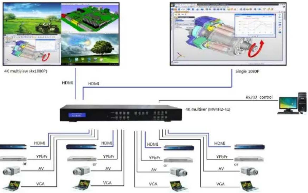
This mode displays the four inputs as a quad view or from a single input to the HDMI outputs independently and in any combinaon as 4K UHD video output signals. Each output can have a dierent display seng.
2. Full HD Mul-View Video Processor
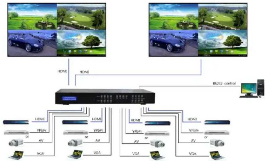
This mode displays all four either inputs as a quad view or from a single input to the HDMI outputs independently as high quality HD video output signals. Both outputs show the same image display.
3. Seamless 4:2 Matrix mode
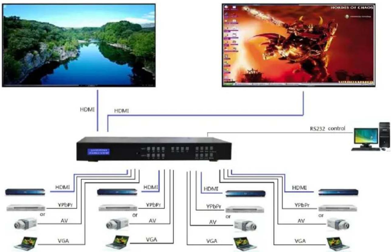
Each input can be switched and routed to any of the two HDMI output ports without any blanking or picture freezing. Each output can display any of the input signals as a single image.
Features
- The SY-APOLLO-4K is a powerful Video Processing device in a 1U rack-mount chassis, with low power consumption (less than 20W).
- Four video inputs, widely compatible to any SD/HD Digital (HDMI/DVI) and SD/HD Analog in AV (CVBS) /YPbPr and VGA input.
-
Each viewer window parameter is completely customizable including layer priority; window posions, window size, background transparency, Border colour including Border pixel width and much more.
• Three operang modes -
UHD 4K Mul-View Video Processor
- Full HD Mul-View Video Processor
-
Seamless 4:2 Matrix
-
Two independent HDMI output ports. When 4K mode selected, user can chose HDMI output to be 4K or Full HD.
- UHD 4K quad Multi-View mode, the HDMI output will present 4 x Full HD signals that will only be visible on a 4K display and each secon of 4 x Full HD signal is pixel by pixel displayed on a large 4K UHD panel without any down scaling degradaon.
- The switching me in the Seamless Matrix mode is one of the fastest in industry due to the very unique switching algorithm used.
Speciication
| Product | Quad Multi-view and seamless matrix 4:2 (APOLLO-4K) |
| HDMI Version | HDMI1.4/DVI |
| HDCP | Yes |
| Input | 4 HDMI, 4 YPbPr or AV, 4 VGA |
| Video Output | 2 HDMI |
| Audio Output | 2 S/PDIF |
| Control | Front panel button, IR or RS232 |
| Power Consumption (max.) | 20 Watts |
| Housing | Metal (steel sheet) |
| Dimension (mm) | L440 x W256 x H42 mm |
| Weight | 2.85 kg |
Application Examples
4K Multi-View Mode
flowchart
graph TD
    A["4K multiview (4x1080P)"] -->|HDMI| B["4K multiver (MV4H2-41)"]
    C["Single 1080P"] -->|HDMI| B
    B -->|RS232 control| D["Computer"]
    B -->|AV| E["Hardware Interface"]
    B -->|VGA| F["Computer Interface"]
    E --> G["Hardware Interface"]
    F --> H["Hardware Interface"]
    style A fill:#f9f,stroke:#333
    style C fill:#f9f,stroke:#333
    style B fill:#ccf,stroke:#333
    style E fill:#cfc,stroke:#333
    style F fill:#fcc,stroke:#333
    style G fill:#ffc,stroke:#333
    style H fill:#fcc,stroke:#333
Full HD Multi-view mode
flowchart
graph TD
    A["Camera 1"] -->|HDMI| B["Central Device"]
    C["Camera 2"] -->|HDMI| B
    D["Camera 3"] -->|HDMI| B
    E["Camera 4"] -->|HDMI| B
    F["Camera 5"] -->|HDMI| B
    G["Camera 6"] -->|HDMI| B
    H["Camera 7"] -->|HDMI| B
    I["Camera 8"] -->|HDMI| B
    J["Camera 9"] -->|HDMI| B
    K["Camera 10"] -->|HDMI| B
    L["Camera 11"] -->|HDMI| B
    M["Camera 12"] -->|HDMI| B
    N["Camera 13"] -->|HDMI| B
    O["Camera 14"] -->|HDMI| B
    P["Camera 15"] -->|HDMI| B
    Q["Camera 16"] -->|HDMI| B
    R["Camera 17"] -->|HDMI| B
    S["Camera 18"] -->|HDMI| B
    T["Camera 19"] -->|HDMI| B
    U["Camera 20"] -->|HDMI| B
    V["Camera 21"] -->|HDMI| B
    W["Camera 22"] -->|HDMI| B
    X["Camera 23"] -->|HDMI| B
    Y["Camera 24"] -->|HDMI| B
    Z["Camera 25"] -->|HDMI| B
    AA["Camera 26"] -->|HDMI| B
    AB["Camera 27"] -->|HDMI| B
    AC["Camera 28"] -->|HDMI| B
    AD["Camera 29"] -->|HDMI| B
    AE["Camera 30"] -->|HDMI| B
    AF["Camera 31"] -->|HDMI| B
    AG["Camera 32"] -->|HDMI| B
    AH["Camera 33"] -->|HDMI| B
    AI["Camera 34"] -->|HDMI| B
    AJ["Camera 35"] -->|HDMI| B
    AK["Camera 36"] -->|HDMI| B
    AL["Camera 37"] -->|HDMI| B
    AM["Camera 38"] -->|HDMI| B
    AN["Camera 39"] -->|HDMI| B
    AO["Camera 40"] -->|HDMI| B
    AP["Camera 41"] -->|HDMI| B
    AQ["Camera 42"] -->|HDMI| B
    AR["Camera 43"] -->|HDMI| B
    AS["Camera 44"] -->|HDMI| B
    AT["Camera 45"] -->|HDMI| B
    AU["Camera 46"] -->|HDMI| B
    AV["Camera 47"] -->|HDMI| B
    AW["Camera 48"] -->|HDMI| B
    AX["Camera 49"] -->|HDMI| B
    AY["Camera 50"] -->|HDMI| B
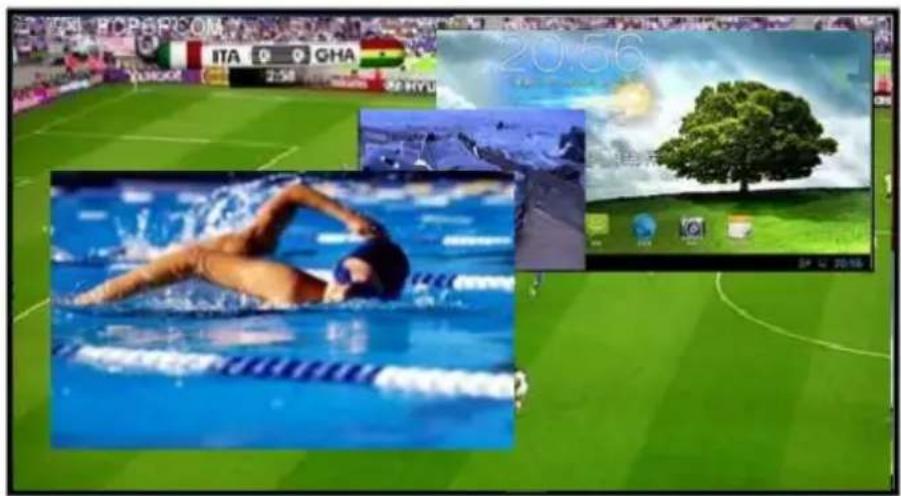
Multi-View Mode
text_image
ITALA 2:58 GHA 20:56 201602 201603 201604 201605 201606 201607 201608 201609 201610 201611 201612 201613 201614 201615 201616 201617 201618 201619 201620 201621 201622 201623 201624 201625 201626 201627 201628 201629 201630 201631 201632 201633 201634 201635 201636 201637 201638 201639 201640 201641 201642 201643 201644 201645 201646 201647 201648 201649 201650 201651 201652 201653 201654 201655 201656 201657 201658 201659 201660 201661 201662 201663 201664 201665 201666 201667 201668 201669 201670 201671 201672 201673 201674 201675 201676 201677 201678 201679 201680 201681 201682 201683 201684 201685 201686 201687 201688 201689 201690 201691 201692 201693 201694 201695 201696 201697 201698 201699 202Display input images on the Mul-View screen to both of the HDMI outputs using 4 window regions that can be congured, via the PC based control soware, to any size and any posion, including borders and prioritized visibility selecon of any overlapped layer for the 4 inputs in the screen windows when using the Mul-View conguraon.
Seamless Matrix Mode
flowchart
graph TD
    A["TV Stream"] -->|HDMI| B["Server"]
    C["HORDES OF CHAOS"] -->|HDMI| B
    B -->|RS232 control| D["Computer"]
    B -->|HDMI, YPbPr, or AV| E["Video Device"]
    B -->|HDMI, YPbPr, or AV, VGA| F["Video Device"]
    B -->|HDMI, YPbPr, or AV, VGA| G["Video Device"]
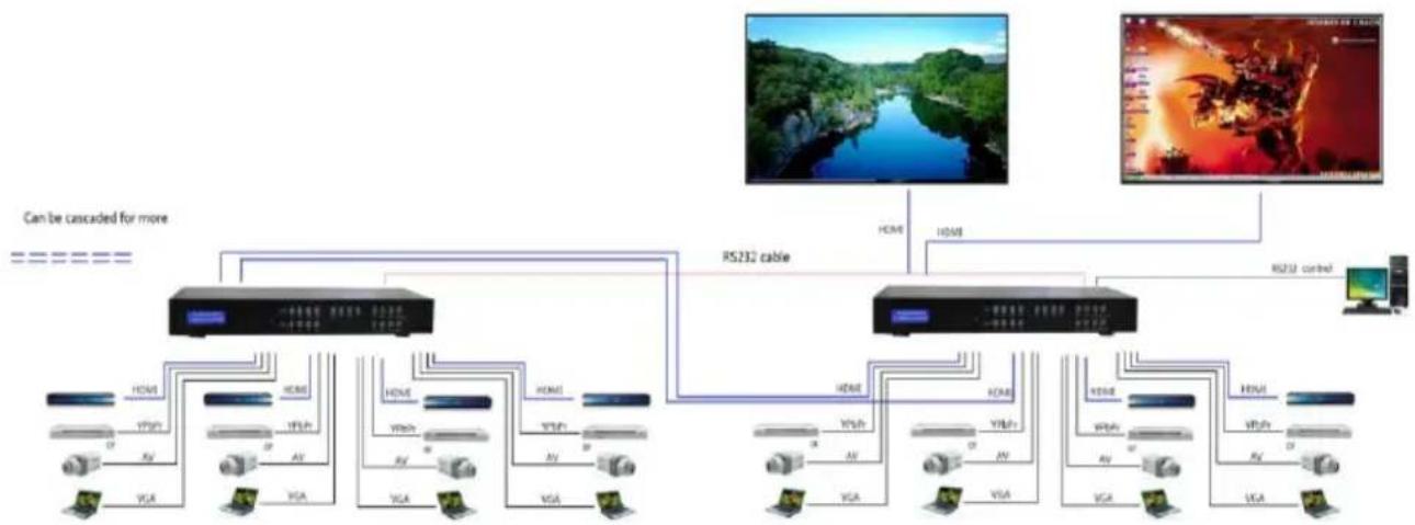
Cascaded for 6x2 Full HD Multi-View mode
flowchart
graph TD
    A["Device 1"] -->|RS232 cable| B["Device 2"]
    C["Device 3"] -->|RS232 cable| B
    D["Computer"] -->|RS232 cable| B
    B -->|RS232 cable| E["Video Panel"]
    B -->|RS232 cable| F["Video Panel"]
    style A fill:#f9f,stroke:#333
    style C fill:#f9f,stroke:#333
    style D fill:#f9f,stroke:#333
    style B fill:#ccf,stroke:#333
    style E fill:#dfd,stroke:#333
    style F fill:#dfd,stroke:#333
This mode allows the creation of matrix systems with more video inputs that can be routed to either of the two output screens. Note that in this mode, the first two HDMI inputs of the right-hand SY-APOLLO-4K are used to cascade the outputs from the left-hand SY-APOLLO-4K. For this mode to operate correctly, each SY-APOLLO-4K devices must be assigned a unique RS232 ID value prior to being connected to the installaoon.
Operation, Controls and Functions
- Connect source devices to input ports of SY-APOLLO-4K.
- If needed, connect RS232 cable from PC RS232 port or USB-RS232 converter to MV4H2 (TDF made USB to RS232 converter cable is highly recommended).
- Connect HDMI output port to TV or other HDMI sink devices.
- Connect 12V/3A power supply to DC power socket.
- Power on the SY-APOLLO-4K, TV and other devices.
Controlling the SY-APOLLO-4K

text_image
APOLLO 4K Multi-Format Swatches, Multi-Voltage OUT11 IN1 IN2 IN3 IN4 HOM1 VISA TPGPI AT A B C D E F G H I J K L M N O P Q R S T U V W X Y Z SY
text_image
OUT1 IN1 IN2 IN3 IN4 HDMI VGA YPbPr AV A B C D 2K QV 4K QV OUT2 OUT1 OUT2- Select input for the desired output port:
Pressing any IN1, IN2, IN3 or IN4 buon will seamlessly change the source of Output 1 or Output 2 to the selected input. - Select source for input groups:
Press HDMI or VGA or YPbPr or AV and then press the input button IN1, IN2, IN3 or IN4, and the input group will change the input to the selected HDMI or VGA or YPbPr or AV (CVBS) input. - Use the 2K QV buon to set the output port to output 1080P quad-view, or use the 4K QV buon to set the output to 4K quad-view on a 4K screen.
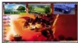
- The 4 buttons (A, B, C, D) set both outputs to multi-viewer mode, with both displays showing the same image. These 4 buons set the SY-APOLLO-4K to output one main picture with the other three inputs shown in PIP mode.
natural_image
Illustration of a volcanic landscape with explosions and smoke, no visible text or symbols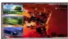
natural_image
Collage of three unrelated natural scenes: a landscape with trees, a car, and a fiery fire (no visible text or symbols)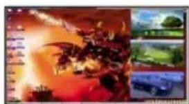
natural_image
Composite image showing a chaotic fire scene with explosions and vehicles, alongside a landscape photo (no visible text or symbols)
natural_image
Composite image showing a fiery explosion scene with multiple landscape photos below (no readable text or symbols)The SY-APOLLO-4K can be cascaded to create a larger system such as an N input seamless switcher, Nx2 seamless matrix or MxN Mulviewer. The RS232 control signals can also be cascaded by using the RS232 cable from the pass through RS232 port to next SY-APOLLO-4K device RS232 port. When more than one SY-APOLLO-4K connected on single RS232 Control chain, each SY-APOLLO-4K device must have unique (dierent) Serial Communicaon address.
Each address can have a binding note, which has at most 10 characters. Aer the address table is saved, they can be selected using the address selecon on main menu for control and management.
SY-APOLLO-4K UART COMMANDS
UART SETTING
115200 bps, 8 data bits, no parity, 1 stop bit, no ow control.
Command format
| Header | length | Group address | Device address | Key word | Parameter | Check sum | |
| Message Type AA = to SY-APOLLO-4K AB = from SY-APOLLO-4K | Device ID | Number of all bytes aer this parameter, including the checksum | See note(1) | See note(1) | See note(2) | Based on the keyword | Check sum See note (3) |
| 1 byte | 2 bytes | 2 bytes (LSB rst) | 1 byte | 1 byte | 2 bytes (LSB rst) | Set by the parameter | 1 byte |
Table 1 - Command Format
Note:
(1) Each SY-APOLLO-4K in a cascaded system must be assigned a unique two byte address. The first byte is the Group Address, the second byte is the Device Address. The two values 0x00 and 0x are invalid for both the Group Address and the Device Address respectively.
(2) All data values are transmied in HEX mode.
(3) The checksum value is the negated sum of all values before the Checksum eld.
The header rst byte denotes the type of data: AAH for a command to the SY-APOLLO-4K, or ABH for a reply from the SY-APOLLO-4K.
The next two header bytes are the device ID where:
XX: is in the range 01H\~FEH, and YY: is in the range 01H\~FEH
The following table lists the ID values that should only be used for the described purpose:
| Group Addr | Device addr | Descripon | Reply From |
| 00H | FFH | Invalid | No reply |
| XXH | FFH | Broadcast to all the devices with the group address of XXH | No reply |
| FFH | FFH | Broadcast to all devices | No reply |
| 00H | 00H | Broadcast to all devices | All devices |
| XXH | 00H | Broadcast to all the devices with the group address of XXH | All in group |
| FFH | 00H | Invalid | No reply |
| 00H | XXH | Invalid | No reply |
| FFH | XXH | Invalid | No reply |
| XXH | YYH | Send data to the device with the address XXYYH | One device |
Table 2 - Addressing the SY-APOLLO-4K
| keyword | Descripon of keyword | Length of parameter | Descripon of parameter | Note |
| WRITE SETTINGS COMMANDS | ||||
| The following commands can only be used while in MODE1 (HD MV) | ||||
| 01H | Set display priority of the 4 input images. | 4 BYTES | Refer to the data from 1 to 4 in Table 4 | |
| 02H | Set the coordinate of the image with the highest priority | 8 BYTES | Refer to the data from 5 to 12 in Table 4 | |
| 03H | Set the coordinate of the image with the second priority | 8 BYTES | Refer to the data from 12 to 20 in Table 4 | |
| 04H | Set the coordinate of the image with the third priority | 8 BYTES | Refer to the data from 21 to 28 in Table 4 | |
| 05H | Set the coordinate of the image with the lowest priority | 8 BYTES | Refer to the data from 29 to 36 in Table 4 | |
| 50H | Set the transparency | 1 BYTE | Refer to Table 5 | |
| 51H | Background colour | 3 BYTES | Refer to Table 6 | |
| The following commands can only be used while in MODE2 (4:2 MX) | ||||
| 1000H | Set the source for the two output ports | 2 BYTES | Refer to Table 7 | |
| The following commands can only be used while in MODE3 (4K) | ||||
| 2000H | 4KMV or the source of single 1080P output | 2 BYTES | Refer to Table 8 | |
| The following commands can only be used while in MODE1 & MODE3 | ||||
| 2820H | Set audio route when in MV mode | 2 BYTES | Refer to Table 9 | |
| 2852H | Color of the image border | 3 BYTES | Refer to Table 6 | |
| 2853H | Width of the image border | 1 BYTE | Refer to Table 10 | |
| The following commands can only be used while in MODE1 & MODE2 & MODE3 | ||||
| 3800H | Select video source for input 4 | 4 BYTES | Refer to Table 11 | |
| 3810H | Select audio source for input 4 | 4 BYTES | Refer to Table 12 | |
| 3838H | Program EDID for HDMI Input or VGA Input | 256 BYTES | Refer to Table 13 | |
| 3840H | Select internal EDID for input HDMI or VGA | 3 BYTES | Refer to Table 14 | |
| The following commands can be used in ALL MODES | ||||
| 7800H | Set the system operang mode | 1 BYTE | Refer to Table 15 | |
| 7801H | Set the device address | 2 BYTES | Refer to Table 16 | |
| 7820H | HDCP DEBUG | 1 BYTE | Refer to Table 18 | |
| 7802H | Factory reset sengs | 0 BYTES | ||
| READ STATUS COMMANDS | ||||
| The following commands can only be used while in MODE1 | ||||
| 8000H | Read coordinate and display priority of 4 images | 0 BYTES | MCU will reply base on Table 4 | |
| 8050H | Read transparency | 0 BYTES | MCU will reply base on Table 5 | |
| 8051H | Read background | 0 BYTES | MCU will reply base on Table 6 | |
| The following commands can only be used while in MODE2 | ||||
| 9000H | Read source of the two output ports | 0 BYTES | MCU will reply base on Table 7 | |
| The following commands can only be used while in MODE3 | ||||
| A000H | Read 4K/single 1080P source | 0 BYTES | MCU will reply base on Table 8 | |
| The following commands can only be used while in MODE1 & MODE3 | ||||
| A820H | Read audio route when in MV mode | 0 BYTES | MCU will reply base on Table 9 | |
| A852H | Read colour of image border line | 0 BYTES | MCU will reply base on Table 6 | |
| A853H | Read width of image border line | 0 BYTES | MCU will reply base on Table 10 | |
| The following commands can only be used while in MODE1 & MODE2 & MODE3 | ||||
| B800H | Read the source of the 4 input groups | 0 BYTES | MCU will reply base on Table 11 | |
| B810H | Read the HDMI audio source | 0 BYTES | MCU will reply base on Table 12 | |
| B820H | Bypass the data from video processors to PC | Based on the data from video processors | MCU will reply base on table-23 | |
| B838H | Read SINK EDID | 1 BYTE | Refer to Table 17 | Refer to Note(2) |
| The following commands can be used in ALL MODES | ||||
| F800H | Read the working mode | 0 BYTES | MCU will reply base on Table 15 | |
| F801H | Read address of the machine | 0 BYTES | MCU will reply base on Table 16 | |
| F820H | Read HDCP mode(on or o) | 0 BYTES | MCU will reply base on Table 18 | |
Table 3 - SY-APOLLO-4K Command Summary
Note:
- To write or set data to SY-APOLLO-4K, the keyword must be less than 8000H.
To read data from SY-APOLLO-4K, the keyword must be greater than or equal to 8000H
PC->SY-APOLLO-4K: AA + ID + 06 00 00 00 38 BB 01 + checksum PC->SY-APOLLO-4K: AA + ID + 06 00 00 00 38 38 \~\~\~\~\~\~ (256 BYTES) + checksum - If the SY-APOLLO-4K fails to read the EDID data from the sink device, the reply to the PC is:
SY-APOLLO-4K ->PC: AB+ ID + 06 00 00 00 38 B8 00 + checksum - If the SY-APOLLO-4K successfully reads the EDID, the reply to the PC is:
SY-APOLLO-4K ->PC: AB + ID + 05 01 00 00 38 B8 \~\~\~\~ (256 BYTES) + checksum
| Byte number | Descripon of the parameter | Note |
| 1 | The source of the image with the highest priority | 0-CH1, 1-CH2, 2-CH3, 3-CH4The 4 data values must be dierent from each other, each in the range 0~3 |
| 2 | The source of the image with the second priority | |
| 3 | The source of the image with the third priority | |
| 4 | The source of the image with the lowest priority | |
| 5 | Low byte of the le-top corner X coordinate of the highest priority image | X coordinate data:0~1919Y coordinate data:0-1079 |
| 6 | High byte of the le-top corner X coordinate of the highest priority image | |
| 7 | Low byte of the le-top corner Y coordinate of the highest priority image | |
| 8 | High byte of the le-top corner Y coordinate of the highest priority image | |
| 9 | Low byte of the right-boom corner X coordinate of the highest priority image | |
| 10 | High byte of the right-boom corner X coordinate of the highest priority image | |
| 11 | Low byte of the right-boom corner Y coordinate of the highest priority image | |
| 12 | High byte of the right-boom corner Y coordinate of the highest priority image | |
| 13 | Low byte of the le-top corner X coordinate of the second priority image | |
| 14 | High byte of the le-top corner X coordinate of the second priority image | |
| 15 | Low byte of the le-top corner Y coordinate of the second priority image | |
| 16 | High byte of the le-top corner Y coordinate of the second priority image | |
| 17 | Low byte of the right-boom corner X coordinate of the second priority image | |
| 18 | High byte of the right-boom corner X coordinate of the second priority image | |
| 19 | Low byte of the right-boom corner Y coordinate of the second priority image | |
| 20 | High byte of the right-boom corner Y coordinate of the second priority image | |
| 21 | Low byte of the le-top corner X coordinate of the third priority image | |
| 22 | High byte of the le-top corner X coordinate of the third priority image | |
| 23 | Low byte of the le-top corner Y coordinate of the third priority image | |
| 24 | High byte of the le-top corner Y coordinate of the third priority image | |
| 25 | Low byte of the right-boom corner X coordinate of the third priority image | |
| 26 | High byte of the right-boom corner X coordinate of the third priority image | |
| 27 | Low byte of the right-boom corner Y coordinate of the third priority image | |
| 28 | High byte of the right-boom corner Y coordinate of the third priority image | |
| 29 | Low byte of the le-top corner X coordinate of the lowest priority image | |
| 30 | High byte of the le-top corner X coordinate of the lowest priority image | |
| 31 | Low byte of the le-top corner Y coordinate of the lowest priority image | |
| 32 | High byte of the le-top corner Y coordinate of the lowest priority image | |
| 33 | Low byte of the right-boom corner X coordinate of the lowest priority image | |
| 34 | High byte of the right-boom corner X coordinate of the lowest priority image | |
| 35 | Low byte of the right-boom corner Y coordinate of the lowest priority image | |
| 36 | High byte of the right-boom corner Y coordinate of the lowest priority image |
Table 4 - Write Sengs Command Details
| Byte number | Descripon | Note |
| 1 | Transparency | 0 = 0%, 1 = 25%, 2 = 50%, 3 = 75% |
Table 5 - Set Transparency Command
| Byte number | Descripon | Note |
| 1 | R value | 0-255 |
| 2 | G value | 0-255 |
| 3 | B value | 0-255 |
Table 6 - Set Colour for Background or Border
| Byte number | Descripon | Note |
| 1 | The source INDEX of output port 1 | 0- No change1- IN12- IN23- IN34- IN4 |
| 2 | The source INDEX of output port 2 |
Table 7 - Set Input Source for Both Outputs
| Byte number | Descripon | Note |
| 1 | Output port 1 mode | 0- No change1- 4K Mul-View Mode2- IN1 in Single Input Mode at 1080p3- IN2 in Single Input Mode at 1080p4- IN3 in Single Input Mode at 1080p5- IN4 in Single Input Mode at 1080p |
| 2 | Output port 2 mode |
Table 8 - Set Quad-View or Single Input View
| Byte number | Descripon | Note |
| 1 | Audio source for output port 1 | 0- No change1- IN1 |
| 2 | Audio source for output port 2 | 2- IN23- IN34- IN4 |
Table 9 - Set Audio Source for Mul-View Mode
| Byte number | Descripon | Note |
| 1 | Width of border line | Value: 0~15. 0-no border line |
Table 10 - Set Image Border Width
| Byte number | Descripon | Note |
| 1 | Video source of IN1 | 0- No change |
| 2 | Video source of IN2 | 1- HDMI, |
| 3 | Video source of IN3 | 2- VGA, |
| 4 | Video source of IN4 | 3- YPBPR, |
| 4- AV |
Table 11 – Input 4 Video Source Select
| Byte number | Descripon | Note |
| 1 | HDMI 1 audio source | 0-No change |
| 2 | HDMI 2 audio source | 1-HDMI audio |
| 3 | HDMI 3 audio source | 2-From VGA audio |
| 4 | HDMI 4 audio source | 3-From YPbPr audio |
Table 12 - Input 4 Audio Source Select
| Byte number | Descripon | Note |
| 1 | Input group | 1-IN1,2-IN2,3-IN3,4-IN4 |
| 2 | EDID port | 1-HDMI,2-VGA |
| 2~257 | EDID data | A Valid EDID Data Block (256 bytes) |
Table 13 - Program EDID Data
| Byte number | Descripon | Note |
| 1 | Input group | 0-ALL,1-IN1,2-IN2,3-IN3,4-IN4 |
| 2 | EDID port | 1-HDMI,2-VGA |
| 3 | EDID number | Numbers start from 0 |
| 1 | Mode Index | 0-HD MV1-3:2 seamless matrix2-4KMV |
Table 14 - Select Internal EDID Data
Table 15 - Set System Operang Mode
| Byte number | Descripon | Note |
| 1 | Group address | 01H~FEH |
| 2 | Device address | 01H~FEH |
Table 16 - Set Device Address
| Byte number | Descripon | Note |
| 1 | Output channel | 1-OUT1,2-OUT2 |
Table 17 - Read Sink EDID
| Byte number | Descripon | Note |
| 1 | HDCP mode | Every bit present one output port. (bit0-output1, bit1-output2)0- Debug(HDCP OFF)1-Normal |
Table 18 - Set HDCP Mode
Safety Instructions
To ensure reliable operaon of this product as well as protecng the safety of any person using or handling these devices while powered, please observe the following instrucons.
- Use the power supplies provided. If an alternate supply is required, check Voltage, polarity and that it has sufficient power to supply the device it is connected to.
- Do not operate either of this product outside the specied temperature and humidity range given in the above speciaons.
- Ensure there is adequate venlaon to allow this product to operate eciently.
- Repair of this equipment should only be carried out by qualified professionals as this product contains sensitive devices that may be damaged by any mistreatment.
- Only use this product in a dry environment. Do not allow any liquids or harmful chemicals to come into contact with this product.
After Sales Service
- Should you experience any problems while using this product, rstly refer to the Troubleshoong secon in this manual before contacng SY Technical Support.
- When calling SY Technical Support, the following informaon should be provided:
• Product name and model number
• Product serial number
• Details of the fault and any condions under which the fault occurs.
-
This product has a two year standard warranty, beginning from the date of purchase as stated on the sales invoice. Online registraon of this product is required to acvate the full three year extended warranty. For full details please refer to our Terms and Conditions.
-
SY Product warranty is automatically void under any of the following conditions:
-
The product is already outside of its warranty period
-
Damage to the product due to incorrect usage or storage
• Damage caused by unauthorised repairs
• Damage caused by mistreatment of the product -
Please direct any quesons or problems you may have to your local dealer before contacting SY Electronics.