
FUNP 610 X - Oven CANDY - Free user manual and instructions
Find the device manual for free FUNP 610 X CANDY in PDF.


| Product Type | Built-in Electric Oven with Vitroceramic Hob |
| Model | FUNP 610 X |
| Brand | Candy |
| Oven Type | Multifunction built-in oven |
| Hob Type | Vitroceramic (compatible with models PVU 640 C, PVU 640 X, PVU 647 X, PVU 647 N) |
| Energy Class (Convection) | B |
| Oven Functions | Defrost, Static (Lower+Upper), Fan+Static, Grill, Grill+Fan, Turbo Fan, Turbo Fan+Lower, Lower Heating, Upper Heating, Double Grill, Double Grill+Fan, Lower+Fan |
| Voltage / Frequency | 220-240 V ~ / 50-60 Hz (also 380-415V 3N~) |
| Timer | Mechanical timer (0-100 minutes) with audible warning |
| Dimensions (Oven) | Approx. 595 x 595 x 550 mm (width x height x depth) |
| Weight | Approx. 35 kg |
| Interior Material | Enamel (catalytic on rear and side walls for some models) |
| Accessories Included | Oven tray, grid, rack |
| Replacement Parts | Oven light bulb (contact Authorised Service) |
| Cleaning | Use cream or liquid cleaners; avoid abrasives; clean interior slightly warm; use spatula for residue |
| Safety Features | Child supervision required; automatic shut-off via timer; earthing required |
| Installation | Built-in; minimum 65 cm above hob with hood, 70 cm without; avoid flammable materials |
| Warranty | Standard manufacturer warranty (contact Authorised Service) |
Frequently Asked Questions - FUNP 610 X CANDY
User questions about FUNP 610 X CANDY
0 question about this device. Answer the ones you know or ask your own.
Ask a new question about this device
Download the instructions for your Oven in PDF format for free! Find your manual FUNP 610 X - CANDY and take your electronic device back in hand. On this page are published all the documents necessary for the use of your device. FUNP 610 X by CANDY.
USER MANUAL FUNP 610 X CANDY
BUILT-IN OVEN AND HOB USER'S MANUAL
ENG
natural_image
Line drawing of three rectangular electronic enclosures with circular holes, one partially filled and one outlined (no text or symbols)ENG
Dear Customer,
Thank you for purchasing this product. The safety precautions and recommendations in these instructions are for your own safety and that of others. They will also provide a means by which to make full use of the features offered by your appliance.
Please keep this booklet in a safe place. It may be useful in future, either to yourself or to others in the event that doubts should arise relating to its operation.
This appliance must be used only for its intended purpose, that is for the domestic cooking of foodstuffs. Any other form of usage is to be considered as inappropriate and therefore dangerous.
The manufacturer declines all responsibility in the event of damage caused by improper or incorrect use of the appliance.
ENG
CONTENTS
1- Introduction of product
2-Warnings
3- Preparation for installation and use
4- Using the oven and hob
5- Cleaning and maintenance
6- Service and Transportation
PART 1: INTRODUCTION OF PRODUCT
ENG
text_image
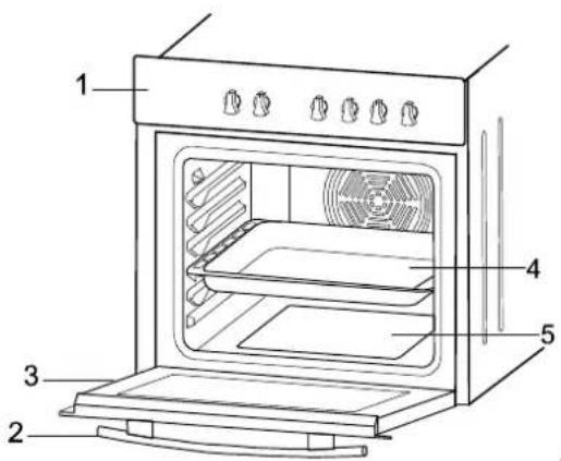
Labeled diagram of an oven with numbered parts for identificationMAIN PARTS
1- Control Panel
2- Oven Door Handle
3- Oven Door
4- Tray
5-Lower Heating Element
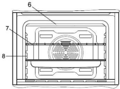
6- Upper Heating Element
7- Grid
8-Racks
text_image
6 7 8| Hob - Oven Combination Possibility | FUNP 610 X | FUNP 611 X | FUHP 615 X | FUHP 825 X | FUS 100-40 W | FUS 100-40 X |
| PVU 640 C | √ √ √ √ | √ | √ | |||
| PVU 640 X | √ | √ | √ | √ | — | — |
| PVU 647 X | √ | √ | √ | √ | — | — |
| PVU 647 N | √ | √ | √ | √ | — | — |
ENG
VITROCERAMIC HOB: PVU 640 C - PVU 640 X
text_image
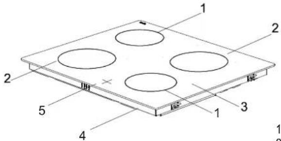
Technical diagram of a multi-layered electronic component with labeled parts 1 through 51 145 Highlight Zone (1200W)
2 180 Highlight Zone (1800W)
3 Vitroceramic Surface
4 Lower Casing
5 Hot Hob Indicator
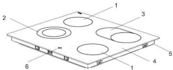
VITROCERAMIC HOB: PVU 647 X - PVU 647 N
text_image
Technical diagram of a multi-layered electronic device with numbered components and mounting holes1 145 Highlight Zone (1200W)
2.b 180 Dual Highlight Zone (1700W)
3 Extensible Highlight Zone (1800W)
4 Vitroceramic Surface
5 Lower Casing
6 Hot Hob Indicator
PART 2: WARNINGS
ENG
BEFORE STARTING TO USE THE APPLIANCE, PLEASE TAKE ALL ESSENTIAL SAFETY MEASURES AND THOROUGHLY READ THE OPERATING MANUAL.
This appliance has been designed for home as built-in furniture.
After removing the packaging, make sure to check if there is any damage to the appliance. If there is any damage, never attempt to use the appliance and immediately contact your Authorised Service. As packaging metarials (nylon, perforator, syrofoam etc.) will pose a threat to children, such metarials need to be collected immediately and put out of reach.
The appliance must be installed and put in operation by an authorised technician under the conditions provided by the manufacturer in this manual. The manufacturer cannot be held responsible for any damage that might occur due to faulty installation.
Before connecting your appliance to the mains at home, make sure to check the conformity of voltage and gas settings, which are specified on the information sticker attached to the appliance and/or packaging, with the usage conditions available.
Do not operate the oven before it is fully installed.
Be sure that all of its knobs are turned off when the appliance is not in use.
Be sure that the power cord is not wedged during the installation of the appliance.
The power cord should never be replaced by the customer. In the event any damage occurs to the power cord for any reason, please contact your Authorised Service.
Switch off the appliance may preserve their heat for a long time; please wait until the parts primarily exposed to heat cool off touching them.
Do not keep flammable items/substances near while it is in use.
When operating other electrical devices near the appliance, pay attention that their cables do not come into contact with the heated parts.
When the appliance is not in use, make sure that the knobs are in "0" (off) position.
Your appliance needs sufficient air circulation while it is operating. Carefully read the part of this manual, where installation procedures are explained, and make sure the relevant conditions are satisfied.
This operating manual has been prepared jointly for multible models. Some of the specifications explained in the manual may not be included in your appliance. Pay attention to the explanations with illustrations while reading the manual.
In case that hi-light halogen heaters are installed as hob elements do not stare into the light.
ENG
This appliance is not intended for use by persons (including children) with reduced physical, sensory or mental capabilities, or lack of experience and knowledge, unless they have been given supervision or instruction concerning use of the appliance by a person responsible for their safety.
Children should be supervised to ensure that they do not play with the appliance.
Pay attention to the following when using your appliance.
Be careful to connect your appliance to an earthed power outlet or line.
Do not place the power cord of your appliance near any heated spot.
Contact the nearest Authorised Service in the event any damage occurs to the power cord
When you first run your oven a certain smell will be emanated arising from the insulation materials and the heater elements. For this reason, before using your oven, run it empty at maximum temperature for 45 minutes. At the same time you need to properly ventilate the environment in which the oven is installed.
Do not touch the interior and the heaters when using the oven part of the appliance as it will be hot. After switching off the burner, do not touch it with your hand before it is completely cooled off.
Do not put flammable and combustible materials into the oven. Do not place combustibles including any pressured container, paper, plastic and fabric near the hob surface.
Be careful when using the oven part of the appliance as the oven outer surface can be hot. Keep children away from the oven.
While the front door is open, do not let children climb on the door or sit on it.
The values indicated on the printed documents found on the product are values obtained in laboratory environment according to relevant standards. These values may vary according to the usage and environment conditions of the product.
For built-in combined products, be sure that the connection of the hob to the oven has been made.
Be sure that the main cable connecting the hob and the oven together is not wedged.
In case you detect any crack on the vitroceramic hob surface, unplug your appliance!
Caution (Only for FUS 100-40 W and FUS 100-40 X models): The heat vapour is given out through the ventilation holes at the handle during normal operation of the oven. Please kindly be aware of that usage.
PART 3 : PREPARATION FOR INSTALLATION AND USE
ENG
natural_image
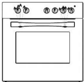
Line drawing of a standard oven with four control knobs and a door (no text or symbols)Manufactured with best quality parts and materials, this modern, functional and practical oven will meet your needs in all respects. Make sure to read this manual to obtain successful results and not to experience any problems in the future. The information given below contain rules that are necessary for correct positioning and service operations. They should be read without fail especially by the technician who will install the appliance.
3.1 CHOOSING A PLACE FOR THE OVEN
There are several points to pay attention to when choosing a place for your oven. Make sure to take into account our recommendations below in order to prevent any problems and dangerous situations, which might occur later!
When choosing a place for the oven, attention should be paid that there are no flammable or combustible materials in the close vicinity, such as curtains, oilcloth etc., which quickly catch fire.
Furnitures surrounding the oven must be made of materials resistant to temperatures above 50C°.
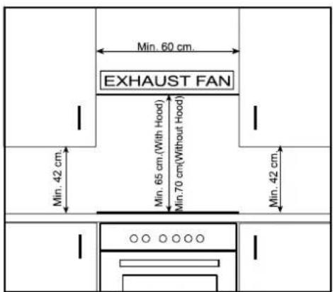
Required changes to wall cabinets and exhaust fans above the built-in combined product as well as minimum heights from the oven board are shown in Figure 1. Accordingly, the exhaust fan should be at a minimum height of 65 cm from the worktop. If there is no exhaust fan the height should not be less than 70 cm.
text_image
Min. 60 cm. EXHAUST FAN Min. 42 cm. Min. 65 cm.(With Hood) Min.70 cm.(Without Hood) Min. 42 cm.Figure 1
ENG
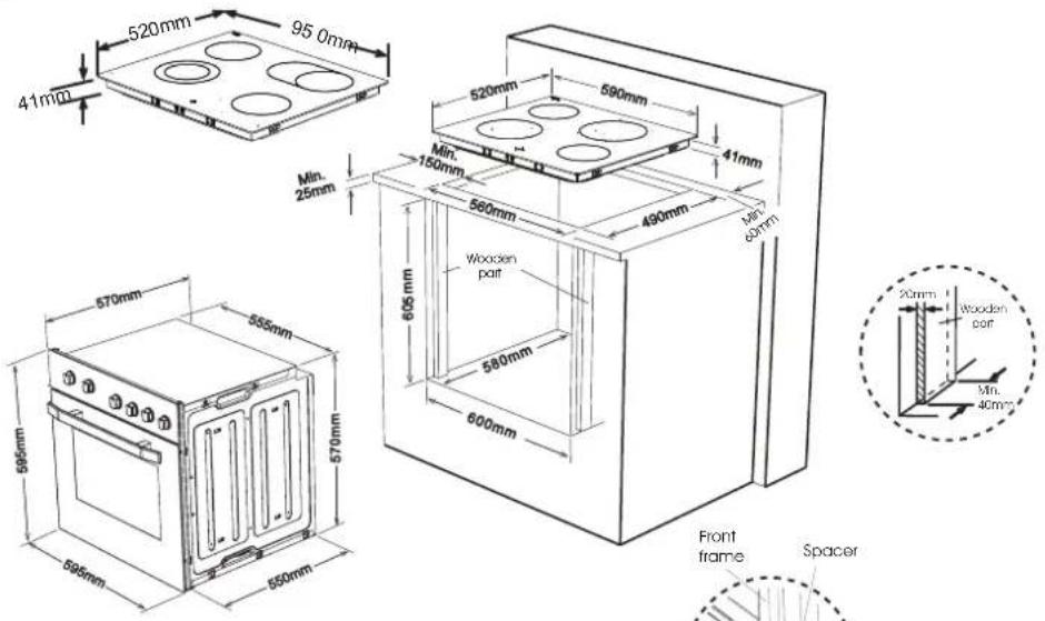
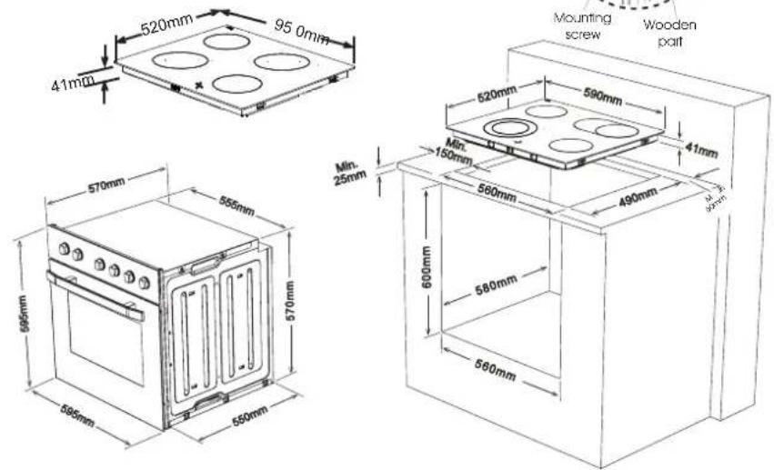
3.2 OVEN and HOB INSTALLATION
Figure A- Flush Installation of Oven
text_image
520mm 95.0mm 41mΩ Min. 25mm 570mm 555mm 570mm 595mm 595mm 550mm 605mm 600mm 580mm 560mm 520mm 590mm 41mm 490mm 41mm Wuxxen part Front frame Spacer 20mm Wooden part Min. 40mmFigure B- Regular Installation of Oven
text_image
520mm 95.0mm 41mm 570mm 555mm 570mm 595mm 650mm Mounting screw Wooden part 520mm 590mm 41mm Min. 150mm 490mm Min. 25mm 600mm 580mm 580mmENG
Installation steps:
- Place the hob into the opening on worktop. The size of opening is given in Figure A. For details, see the heading Fixing the vitroceramic hob.
- Connect the hob to the oven using the plug given on the hob. The socket for plug is placed on the rear panel of oven.
- Connect the oven to the electrical supply.
- Place the oven into its built-in niche. Either placement in Figure A or placement in Figure B is applicable depending on the size of cabinet opening. For details, see the heading Fixing the oven.
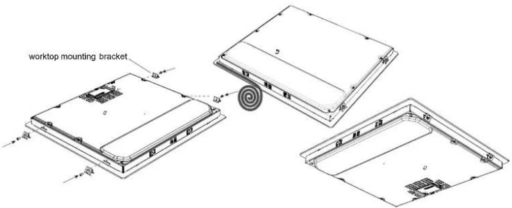
Fixing the vitroceramic hob:
- Apply the one-sided self-adhesive sealing tape supplied all the way round the lower edge of the cooking surface along the outer edge of the glass ceramic panel. Do not stretch it.
- Screw the 4 worktop mounting brackets on the side walls of product.
- Place the hob into the opening on the worktop.
text_image
worktop mounting bracket 12 13 14 15 16 17 18 19 20ENG
Fixing the oven:
Insert the oven into cabinet partly by pushing it forward. Open the oven door and insert 4 screws into countersunk holes on the front frame. Locate the spacers behind the flange of front frame and screw them till the surface of spacer touches the front frame. While doing this, please pay attention that the chamfered edge of each spacer is faced to the rounded edge of front frame. Push forward the product completely and finally screw it to wooden part.
The dimensions and material of the cabinet in which the oven will be installed must be correct and resistant to increases in temperature. In a correct installation, contact with electrical or insulated parts must be pervented. Insulating parts need to be fitted in a way to ensure that they cannot be removed by using any kind of tool. Installing the appliance in the close vicinity of a refrigerator or a deep-freezer is not recommended. Otherwise, the performance of the above-mentioned appliances will be negatively affected due to emanating heat.
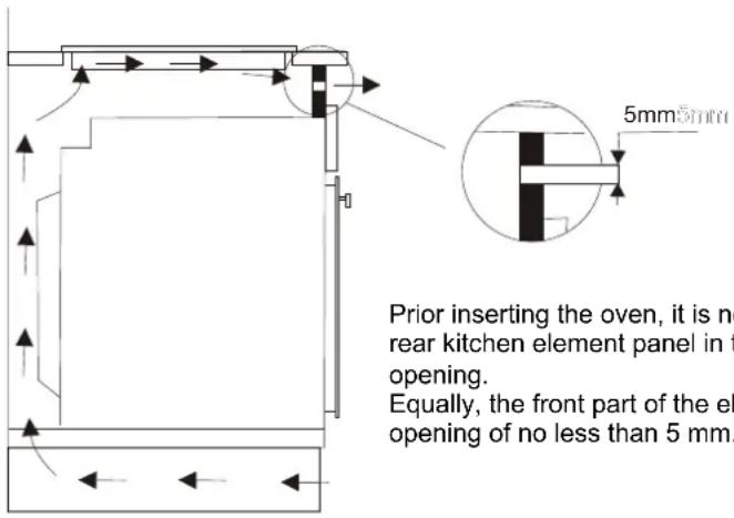
Warning regarding the installation of built-in oven without cooling fan( FUS 100-40 W FUS 100-40 X )
text_image
5mm5mm Prior inserting the oven, it is no rear kitchen element panel in the opening. Equally, the front part of the el opening of no less than 5 mm.Prior inserting the oven, it is necessary to remove the rear kitchen element panel in the area of the oven opening.
Equally, the front part of the element must have an opening of no less than 5 mm.
ENG
3.3 WIRING AND SAFETY OF THE BUILT-IN OVEN :
The instructions given below must be followed without fail during wiring:
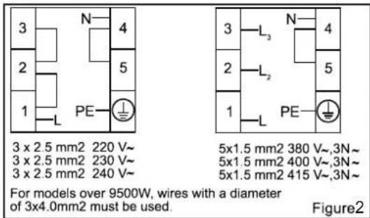
The earthing cable must be connected via the screw with the earthing mark ( ).Power cord connection must be as shown in Figure 2. If there is no earthed outlet conforming to regulations in the installation environment, call the Authorised Service immediately.
The earthed outlet must be in close vicinity of the appliance. Never use an extension cord.
The feeder cable should not contact the product's hot surface.
In case of any damage to the power cord, make sure to call the Authorised Service. The cable must be replaced by the Authorised Service.
Wiring of the appliance must be performed by the Authorised Service. H05VV-F type power cord must be used.
Faulty wiring may damage the appliance. Such a damage will not be covered under the warranty.
The appliance is designed to connect to 220-240V\~ and 380-415V 3N \~ electricity. If the mains electricity is different than the value given above, call the Authorised Service immediately.
The Manufacturer Firm declares that it bears no responsibility whatsoever for any kind of damage and loss arising from not complying with safety norms!
ATTENTION:
Should it be necessary to replace the supply cord, connect the wire in accordance with the following colours/codes:
BLUE - NEUTRAL (N)
BROWN - LIVE (L)
YELLOW-GREEN - EARTH ( )
⊕
ENG
3.4 WIRING AND SAFETY OF THE BUILT-IN COMBINED OVEN :
Wiring of the appliance must be performed by the Authorised Service. The appliance is designed to connect to 220-240V\~ and 380-415V 3N \~ electricity. If the mains electricity is different than the value given above, call the Authorised Service immediately.
Connection of the appliance must be as shown in Figure 2. The appliance is designed for fixed connection to the mains. There is to install an all pole disconnector inside the supply circuit with a contact opening of at least 3mm (rated 32A, delay functioning type)
WARNING: The cablying and wiring system must be able to bear the maximum electric power required by the oven. This is indicated on the rating plate oven. In case of any doubt, please refer to professionals.
text_image
3 x 2.5 mm2 220 V~ 3 x 2.5 mm2 230 V~ 3 x 2.5 mm2 240 V~ PE N 4 5 1 3 L₃ N 4 2 L₂ 5 1 PE L For models over 9500W, wires with a diameter of 3x4.0mm2 must be used. 5x1.5 mm2 380 V~,3N~ 5x1.5 mm2 400 V~,3N~ 5x1.5 mm2 415 V~,3N~ Figure23.5 GENERAL WARNING AND PRECAUTIONS :
Your appliance is produced in conformity with the relevant safety instructions relating to electrical appliances. Maintenance and repair works must be performed only by Authorised Service technicians trained by the manufacturer firm. Installation and repair works performed without observing the rules may be dangerous.
The outer surfaces is heated while your appliance is operating. The elements heating the inner surface of the oven and the steam coming out are extremely hot. These sections will continue to preserve their heat for a certain while even if the appliance is switched off. Never touch the hot surfaces. Keep children away.
Do not move away from the hob while cooking with fat or oil. Flaring may occur in case of overheating. Never pour water into flaring oil. In order to choke the resulting flame, close the lid of the pot or the pan and immediately switch off the hob.
In order to cook in your oven, the oven function and temperature setting buttons need to be adjusted and the oven timer, if available, needs to be programmed. Otherwise, the oven will not operate.
While the oven door or drawer is open, do not place anything on it. You may disturb the balance of the appliance or break the door.
Unplug your appliance when it is not in use.
Protect your appliance from atmospheric effects. Do not leave it under the effects of the sun, rain, snow, dust etc.
PART 4: USING THE OVEN
ENG
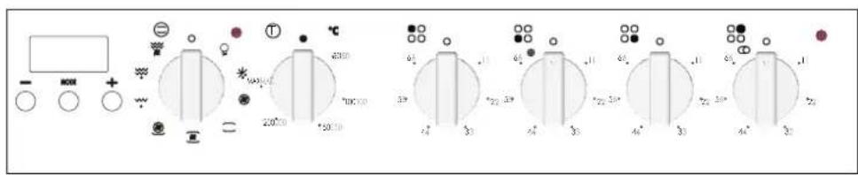
4.1 CONTROL PANELS:
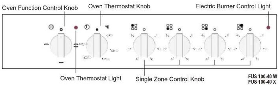
text_image
Oven Function Control Knob Oven Thermostat Knob Electric Burner Control Light Oven Thermostat Light Single Zone Control Knob FUS 100-40 W FUS 100-40 X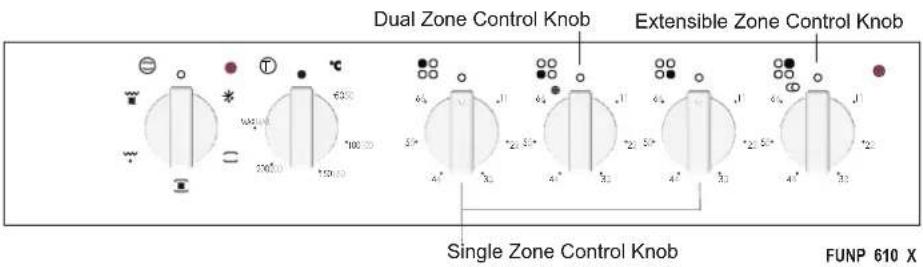
text_image
Dual Zone Control Knob Extensible Zone Control Knob Single Zone Control Knob FUNP 610 XMechanic Timer
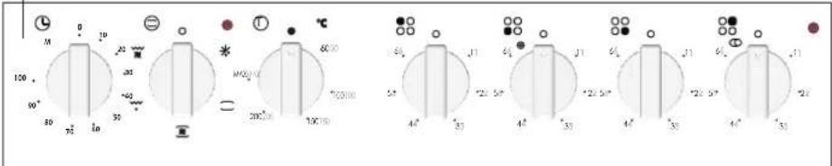
text_image
100 90° 30 75° 10 20 30 *40 *60 M100/10 200/10 100/10 60/10 *100/10 5° 4° 33 *25 5° 4° 35 *25 5° 4° 35 *25 5° 4° 33 *25FUNP 611 X
ENG
Electronic Timer

text_image
Circuit component display showing multiple rotary switches with labeled voltage and current readingsFUHP 615 X

text_image
Circuit diagram with labeled components and measurement scales, showing connections between terminals and switchesFUHP 825 X
ENG
4.2 USING THE COOKTOP BURNERS:
The hob part of the product is controlled by energy regulators. Please see Figure 3.
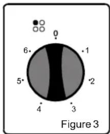
text_image
0 6 1 5 2 4 3 Figure 3Burner control knob
1.... Keeping warm
2 - 3....Heating in Low Temperature
4-5-6...Cooking, Frying and Boiling
While using the electric burners, attention should be paid that the pots used have smooth even bottoms. You can obtain maximum performance from your hob if you use pots with suitable diameters and even bottoms. Using pots with small diameters on burners with large diameters is not recommended. Because that will cause heat loss and lead to a waste of energy.
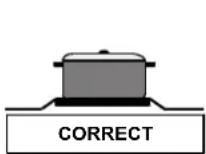
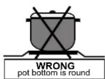
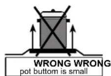
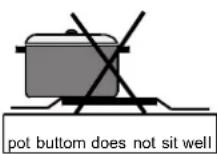
Resistance of the vitroceramic glass to heat and extreme changes of temperature is very high. A redness will be noticed on the heated surface with time. When any heating unit is run, you may hear a weak sound; this is normal and it has to do with the technical structure of the system.
It does not pose any problems in terms of quality. In case sharp-edged pts should rub against or roughly placed on the vitroceramic glass, the surface may be come damaged. It is recommended that you pay attention to this.
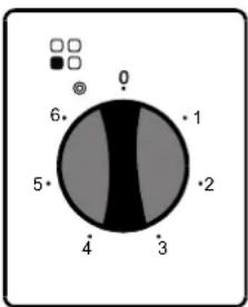
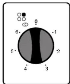
Dual or Extensible Zone Vitroceramic Burner (PVU 647 X-PVU 647 N)
text_image
0 6 5 4 3 2 1Dual or extensible zone vitroceramic burners can heat in two different position. For operating the big diameter of dual zone vitroceramic burner turn the switch to " ☉". Both big and small diameter of the burner will operate. For operating the extensible part of the extensible zone vitroceramic burner, turn the switch to " ☉". Both extensible and round parts will operate.
text_image
0 6 1 5 2 4 3ENG
WARNINGS
When a cooktop burner knob is brought to another position other than the "0" position, the operation light will be on.
Use only pots which fit the burner diameter.
Before placing the pot on the burner, be sure that its bottom is not wet.
Never operate a cooktop burner while empty. Pot temperature may be high when the appliance is in use. Therefore, it is recommended that you keep children and pets away from the hob both during and after operation.
In case you notice any crack on the ceramic glass, it must be immediately switched off and replaced by the Authorised Service.
In order to prevent waste of energy, the pots to be used should not be smaller or larger than the burner surfaces.
Take the necessary measures so that small children will not come close to the burner surface in any way, as it will be hot in operating position.
Due to the flammable nature of hot oil, operations such as frying should be performed with the container lids closed.
Do not cut anything, bread etc., on the glass. Do not use pots with aluminium bottoms. Avoid placing too heavy materials on your hob.
Do not place materials such as plastic, aluminium on the ceramic glass surface. If for any reason there should be a plastic or aluminium material melted on it, clean it up with a spatula immediately.
Do not wipe the ceramic surface with materials such as dish cloth or sponge. Residues of detergents may lead to fire as well as cause the glass colour to fade.
ENG
4.3 USING THE OVEN:
First, you need to adjust the oven function (see figure 4) and then set the oven temperature to desired value (see figure 5). Otherwise, the oven will not operate.
When the temperature inside your oven reaches the value you set, the thermostat will cut the circuit and the thermostat light will go off. When the temperature falls below the set value, the thermostat will again be turned on and the thermostat light will be on.
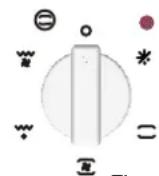
Figure 4
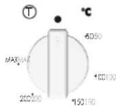
Figure 5
Table 1
| Symbol | Explanation | Energy Class according to CENELEC EN 50304 |
 | Your oven's lamp starts to operating. | |
 | The oven light, the red warning light and the fan will be turned on. Performs the function of defrosting the frozen foods. | — |
 —— —— | The oven's thermostat and warning lights and the lower and upper heating elements will be switched on. | B (convection) for FUNP 610 X A (convection) for FUNP 611 X, FUHP 615 X-825 X, FUS 100-40 X-W |
 | The oven's thermostat and warning lights, the fan and the turbo heater will be switched on. | B (forced air) for FUNP 610 X A (forced air) for FUNP 611 X, FUHP 615 X- 825 X |
 —— —— | The oven's thermostat and warning lights, the grill heater function will be switched on. | — |
 | The oven's thermostat and warning lights, the upper heating element, the grill heater, the fan function will be switched on. | — |
 | Your oven's thermostat and warning lamps and turbo heater, fanare put into use. | — |
| [27Y8] —— | Your oven's thermostat and warning lamps, turbo heater, lower heater and fan start operating. | — |
 | The oven's upper heating element will be switched on. | — |
| — | The oven's lower heating element will be switched on. | — |
| ENG |
| Your oven's thermostat and warning lamps and upper heater, grill heater and start operating. | — | |
| Your oven's thermostat and warning lamps and upper heater, grill heater and fan start operating. | — | |
| Your oven's thermostat and warning lamps, lower heater and start operating. | — |
4.4 FUNCTIONS:
Availability of the functions explained below vary depending on the product model.

Defrost Function :
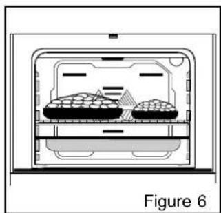
natural_image
Diagram of a food delivery container with two plates and a tray, labeled Figure 6 (no text or symbols on the diagram itself)You can start the defrost operation by putting the frozen food into the oven and bringing the button to the indicated mark. This function does not cook/bake the food; it only helps defrost it within a short time. Put the food to be defrosted on the wire rack that you will place on the third rack support from the bottom (Figure 6). To collect the water to accumulate due to the melting ice, insert an oven tray into the lower rack.

Lower-Upper Heating Element Function (Static Cooking):
In this type of cooking which is described as the traditional method, the heat emanating evenly from the lower and upper resistors into the oven ensures even cooking of the lower and upper side of the food that you are cooking. Adjusted the mostat knob a temperature recommended on the cooking table for the cooking operation you will perform. A preheating of the oven for about 10 minutes is recommended. Leave the food to cook, which is placed in a suitable container, for the recommended duration. This position is a preferred function in making cakes, sponge cakes, pastry, baked pasta, lasagne, pizza.
After the cooking/baking, turn off the oven function control and the thermostat. Take the cooked/baked food out of the oven, place it on a safe place and ensure that the oven completely cools off by keeping the oven door open. As the oven will be hot, stay away from the oven and keep your children away as well.
ENG

Fan and the Lower-Upper Heating Element Function (Static Cooking With Fan) :
This is the position where the air coming from the lower and upper heating elements is circulated into the ovenby the fan.
Adjust the thermostat of your oven to a temperature recommended on the cooking table for the cooking operation you will perform. Turn the oven start will point to the symbol of this function, adjust the oven timer to the recommended time for the cooking and preheat the oven for about 10 minutes. The food placed in a suitable container is put into the oven and the operation is started. This position is a position where usually very good results are obtained in baking pastry. All parts of the foods will be cooked evenly in this position.
Suitable for cooking with one tray.
After the cooking/baking, turn off the oven function control knob the temperature setting. Take the cooked/baked food out of the oven, place it on a safe place and ensure that the oven completely cools off by keeping the oven door open. As the oven will be hot, stay away from the oven and keep your children away.

Grill Function :
This function is used for grills, roast chicken and roast on skewer. For grills; put the foods on the grid and placebo the grid highest rack. After placing the oven tray on the third rack, you can start the grill operation. The tray placed on the third rack will ensure that the oil dropping from the foods will be collected.
When grilling, the oven door must be closed and the oven temperature should be adjusted to 190^ C.
Turn your oven's thermostat goodwill point to this temperature value. After a preheating period of 5 minutes, put your foods into the oven.
After the cooking, turn off the oven function control and the thermostat
Take the cooked/baked food out of the oven, place it on a safe place and ensure that the oven completely cools off by keeping the oven door open. As the oven will be hot, stay away from the oven and keep your children away.

Grill and Fan Function :
At this function; ensuring complete frying by working together the fan, grill and upper heating element perform the operation.
For grills; put the foods on the grid, and place the grid on the highest rack. After placing the oven tray on the third rack, you can start the grill operation. The tray placed on the third rack will ensure that the oil dropping from the foods will be collected.
When grilling, the oven door must be closed and the oven temperature should be adjusted to 190°C.
ENG

TurboFan Function
The turbo fan function evenly disperses the heat in the oven. All foods on all racks will be cooked evenly.
Adjust the thermostat button to the desired degree. Turn the function button so it will point to the Turbo function symbol. After completing the preheating of 10 minutes, place the foods into the oven, which need to be put into suitable containers. This function is suitable for cooking multiple dishes.
If you are going to cook using two trays at the same time; while adjusting the cooking temperature, select the temperature that is the lowest among the levels suitable for your foods, as shown on the table. Cooking with two trays requires additional cooking time compared to cooking with one tray. Usually, the foods on both trays do not finish at the same time. Therefore, take the tray out of the oven, which you observed is finished, and continue the cooking operation for the other tray.
After the cooking/baking, turn off the oven function control button and the thermostat button and cancel the timer program if available. Take the cooked/baked food out of the oven, place it on a safe place and ensure that the oven completely cools off by keeping the oven door open. As the oven will be hot, stay away from the oven and keep your children away as well.

Turbo Fan and Lower heater Function
Turbo Fan and the Lower Heating Element Function is ideal for baking pizza. While the turbo fan evenly disperses the heat of the oven, the lower heating element ensures the baking of the pizza dough. Adjust your oven's function button so it will point to the symbol of this function. After a preheating period of 10 minutes, put your foods into the oven.
After the cooking, turn off the oven function control button and the thermostat button and cancel the timer program. Take the cooked/baked food out of the oven, place it on a safe place and ensure that the oven completely cools off by keeping the oven door open. As the oven will be hot, stay away from the oven and keep your children away as well.
Turbo Fan and the Lower Heating Element Function is ideal for baking pizza. While the turbo fan evenly disperses the heat of the oven, the lower heating element ensures the baking of the pizza dough.

Lower Heating Function
At this cooking, the best is spreaded from the lower heating element. Lower heating function is appropriate for heating the food instead of cooking.

Upper Heating Function
In this type of cooking, the heat emanating from upper heating element cooks the upper side of the food. Upper heating function is appropriate for frying the upper side of already cooked food and heating the food.
ENG

Double Grill Function
At this function the grill and the upper heating element perform the operation. This function is used for roast chicken and roast on skewer. For grills; put the foods on the grill, and the grill on the highest rack. After placing the oven tray on the 3. rack, you can start the grill operation. 3. the tray placed on the 3. rack will ensure that the oil dropping from the foods will be collected.
When grilling the oven door must be closed and the oven temperature should be adjusted to 190.
Turn your oven's thermostat kooibwill point to this temperature value. After a preheating period of 5 minutes, put your foods into the oven.
After the cooking, turn off the oven function control and the thermostat
Take the cooked/baked food out of the oven, place it on a safe place and ensure that the oven completely cools off by keeping the oven door open. As the oven will be hot, stay away from the oven and keep your children away.

Double Grill and Fan Function
At this function; ensuring complete frying by working together, the fan, the grill and the upper heating element perform the operation. It is also used for faster grills and for grills on a larger surface, roast chicken and roast on skewer. For grills; put the foods on the grill and the grillon the highest rack. After placing the oven tray on the 3. rack, you can start the grill operation.
- The tray placed on the 3. rack will ensure that the oil dropping from the foods will be collected. When grilling, the oven door must be closed and the oven temperature should be adjusted to 190°.
Turn your oven's thermostat button so it will point to this temperature value. After a preheating period of 5 minutes, put your foods into the oven.
After the cooking, turn off the oven function control button and the thermostat button and cancel the timer program. Take the cooked/bakedfood out of the oven, place it on a safe place and ensure that the oven completely cools off by keeping the oven door open. As the oven will be hot, stay away from the oven and keep your children away as well.

Lower Heater and Fan Function
At this cooking, the heat is spreaded from the lower heating element and fan motor. This function can be used to heat the food equally in a short time.
| DISHES | TURBO FAN | LOWER-UPPER | LOWER-UPPER FAN | GRILL | ||||||||
| Thermostat pos.(°C) | Rack pos. | Cooking period(°ur.) | Thermostat pos.(°C) | Rack pos. | Cooking period(°ur) | Thermostat pos.(°C) | Rack pos. | Cooking period(°ur) | Thermostat pos.(°C) | Rack pos. | Cooking period(°ur) | |
| Layered pastry | 170 - 190 | 2 - 3 - 4 | 35 - 45 | 170 - 190 | 2 - 3 | 35 - 45 | 170 - 190 | 2 - 3 | 25 - 35 | |||
| Cake | 150 - 170 | 2 - 3 - 4 | 30 - 40 | 170 - 190 | 2 - 3 | 30 - 40 | 150 - 170 | 2 - 3 - 4 | 25 - 35 | |||
| Cookie | 150 - 170 | 2 - 3 - 4 | 25 - 35 | 170 - 190 | 2 - 3 | 30 - 40 | 150 - 170 | 2 - 3 - 4 | 25 - 35 | |||
| Grilled meatballs | 200 | 5 | 10 - 15 | |||||||||
| Watery food | 175 - 200 | 3 | 40 - 50 | 175 - 200 | 3 | 40 - 50 | 175 - 200 | 3 | 40 - 50 | |||
| Chicken | 200 | 2 - 3 | 45 - 60 | 200 | 2 - 3 | 45 - 60 | 200 | ★ | 50 - 60 | |||
| Chop | 200 | 4 - 5 | 15 - 25 | |||||||||
| Beefstake | 200 | 5 | 15 - 25 | |||||||||
| Two-tray cake | 160 - 180 | 2 - 5 | 30 - 40 | |||||||||
| Two-tray pastry | 170 - 190 | 2 - 5 | 35 - 45 | |||||||||
| * Cook with roast chicken skewer.... | ||||||||||||
ENG
USING THE MECHANIC TIMER :
L
text_image
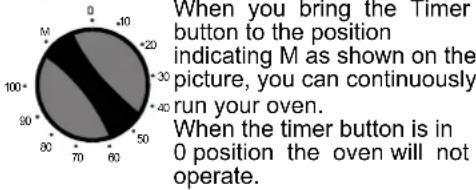
When you bring the Timer button to the position indicating M as shown on the picture, you can continuously run your oven. When the timer button is in 0 position the oven will not operate.Manuel Operation
Operating by adjusting the time
Rotate the timer button clock to a certain time range between 0-100 minutes, as shown on the picture. The oven will stop when the set time range is completed, and the timer will give an audible warning once.

USING THE DIGITAL TIMER :
Time Adjustment :
text_image
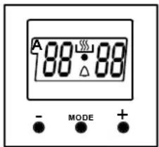
A 88°·88° - MODE +The time must be adjusted before starting to use the oven. Following the power supply to the oven, the symbol (A) and the three "0"s on the screen will begin to flash. Press the (+) and (-) keys simultaneously. The ⚪ symbol will appear on the screen. Also, the dot in the middle of the screen will begin to flash. Using the (+) and (-) keys, adjust the day's time while this dot is flashing. After the adjustment, it should be expected that the dot will be lit continuously.
Following the power supply to the oven, when the symbol (A) and the three « 0 »s on the screen begin to flash, the oven cannot be operated using the control buttons. When the (+) and (-) keys are pressed simultaneously for time adjustment, the ⌘ symbol will appear on the screen. When this symbol appears on the screen, you can manually operate the oven part.

As the adjusted time will be reset in the event of a power failure, time adjustment operation will have to be performed again.
Audible Warning Time Adjustment :
text_image
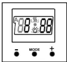
A 188:88 - MODE +This function can be used to receive audible warning at the completion of the adjusted time period.
Press the MODE key in the middle. The symbol will flash on the screen. Also, three "0"s will appear. Adjust the desired time period for the warning by using (+) and (-) keys while the △ symbol is flashing. Some time after the completion of the adjustment, the △ symbol will begin to light continuously. When the △ symbol begins to light continuously, the audible warning time adjustment is done.
ENG
The audible warning time can be set to a time between the time range of 0 and 23.59.
When the time is up, the timer gives an audible warning and the symbol begins to flash on the screen. Pressing any key will stop the audible warning and the symbol disappears on the screen.
Audible Warning Time Adjustment is for warning purposes only. The oven will not be activated at this function.
Semi- Automatic Programming According to Cooking Period :
text_image
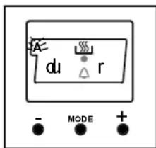
A du r - MODE +Figure 14
This function is used to cook in the desired time range. The foods to be cooked are put into the oven. The oven is adjusted to the desired cooking function. The oven thermostat is adjusted to the desired degree depending on the dish to be cooked.
Keep pressing on the MODE button until you see "stop" on the timer screen. When you see "stop" on the timer screen, the symbol (A) will begin to flash. Adjust the cooking period for the food you wish to cook, by using the (+) and (-) keys while the timer is in this position. Some time after the adjustment operation is completed, the day's time will appear on the screen and the symbols (A) and ⚗ will begin to continuously light on the screen. While doing this, the oven will also start to operate.
A cooking period between the time range of 0 and 10 hours can be set.
At the completion of the set duration, the timer will stop the oven and give an audible warning. Also, the symbol (A) will begin to flash on the screen. After bringing the oven button and oven thermostat button to 0 position, pressing any button of the timer will end the audible warning. Also, the timer will be brought to manual use function.
text_image
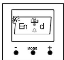
A En d - MODE +Figure 15
Semi-Automatic Programming According to Finishing Time :
This function is used to cook according to the desired finishing time. The food to be cooked is put into the oven. The oven is adjusted to the desired cooking function. The oven thermostat is adjusted to the desired degree depending on the dish to be cooked. Keep pressing on the MODE button until you see "end" on the timer screen. When you see "end" on the timer screen, the symbol (A) and the day's time will respectively begin to flash.
Adjust the finishing time for the food you wish to cook, by using the (+) and (-) keys while the timer is in this position. Some time after the adjustment operation is completed, the day's time will appear on the screen and the symbols (A) and will begin to continuously light on the screen. While doing this, the oven will also start to operate.
You can set a time which can be up to 10 hours after the day's time.
At the completion of the set duration, the timer will stop the oven and give an audible warning. Also, the symbol (A) will begin to flash on the screen. After bringing the oven button and oven thermostat button to 0 position, pressing any button of the timer will end the audible warning. Also, the timer will be brought to manual use function.
ENG
Full- -Automatic Programming :
First; keep pressing on the MODE button until you see "stop" on the timer screen. When you see "stop" on the timer screen, the symbol (A) will begin to flash. Adjust the cooking period for the food you wish to cook, by using the (+) and (-) keys while the timer is in this position. Some time after the adjustment operation is completed, the day's time will appear on the screen and the symbols (A) and ____ will begin to continuously light on the screen (Figure 14).
A cooking period between the time range of 0 and 10 hours can be set.
Second; keep pressing on the MODE button until you see "end" on the timer screen. When you see "end" on the timer screen, the symbol (A) and the day's time will begin to flash, with the addition of the set cooking period. Adjust the finishing time for the food, by using the (+) and (-) keys while the timer is in this position. Some time after the adjustment operation is completed, the day's time will appear on the screen and the symbol (A) will begin to continuously light on the screen (Figure 15).
You can set a time which can be up 23.59 hours after the time obtained by adding the cooking period to the day's time.
The oven will start operating at the time calculated by deducting the cooking period from the set finishing time, and will stop at the set finishing time. The timer will give an audible warning and the symbol (A) will begin to flash. After bringing the oven button and oven thermostat button to 0 position, pressing any button of the timer will end the audible warning. Also, the timer will be brought to manual use function.
PART 5 : CLEANING AND MAINTENANCE
ENG
5.1 GENERAL
Before starting to clean your oven, be sure that all control knobs are off and your appliance is cooled diff. tolerance. pp
Do not use cleaning materials containing particles that might scratch the enamided painted parts of your oven. Use cream cleaners or liquid cleaners, which do not contain particles.
As they might harm the surfaces, do not use caustic creams, abrasive cleaning powders, rough wire wool or hard tools. In the event the excess liquids spilling over you even should burn, it may cause a damage to the enamel. Immediately clean up the liquids. Do not use steam cleaners for cleaning the oven.
5.2 CLEANING THE OVEN
Make sure to unplug the oven before starting to clean it. You will obtain best results if you clean the oven interior while the oven is slightly warm. Wipe your oven with a soft piece of cloth dampened with soap water after each use. Then wipe it again, this time with a wetted cloth and wipe it dry. A complete cleaning may be necessary from time to time, using a liquid cleaning material. Do not clean using dry and powder type cleaners. For products with catalytic enamel frames, the rear and side walls of the inner frame do not require cleaning. However; depending on usage, it is recommended that you replace them after a certain period of time.
5.3 CLEANING THE VITROCERAMIC HOB
Unplug the appliance before starting the cleaning.
Wait for the vitroceramic glass to completely cool off before starting the cleaning.
Make sure that the cleaning materials you will use do not contain particles that might scratch the plasseam detergents or liquid detergents.
The vitroceramic surface should be wiped with cold water and wiped dry with a soft piece of cloth until no cleaning material is left on the surface.
You can use the cleaning spatula if supplied together with your product, for the cleaning spilt foods and residue.
Dessert type of foods should be cleaned immediately after they spill without waiting for the vitroceramic glass to cool off.
Scrubbing with steel cleaning wires may harm the vitroceramic glass surface. Formations of dust on the surface should be cleaned up using a dampened cloth.
Changes in colour which might occur on the ceramic glass surface do not affect the forticture or permanence of the vitroceramic. The reason for the changes in colour is not the change material; it may be because the burnt residues on the surface are not cleaned up or the posted have worn the glass surface or because unsuitable cleaning materials were used. The cleaning spatula should always be used prior to chemical cleaning substances. With this spatula, you can cleanup the tiniest of dirtson the vitroceramic surface Dirts that are difficult to remove such as melted plastic, heavy oils, sweet substances, can be removed easily with the spatula. As the spatula includes a razor, it is dangerous and must be kept out of reach of children. Duringcleaning with the spatula, pay attention not to scrape off the silicon adhesives fothe sides of the glass.
ENG
5.4 MAINTENANCE
Replacing the Oven Light Bulb
It is recommended that you leave this operation to the Authorised Service. Unplug the oven first and make sure that it is cold. After removing the lid in front of the light, take the bulb out. Insert the new bulb resistant to which you will find at Authorised Services, into the place of the bulb you have removed. Then fit the light protected back into its place. After that your oven will be ready for use.
PART 6 : SERVICE AND TRANSPORTATION
ENG
6.1 REQUIREMENTS BEFORE CONTACTING TO SERVICE
If the oven does not operate ;
The oven may be plugged off, there has been a black out.
If the oven does not heat ;
The temperature may be not adjusted with oven's temperature control switch.
If the oven light does not operate does not light;
The electricity should be controlled.
It should be controlled whether the defective.
Cooking (If lower-upper part does not cook equally);
Control the shelf locations, cooking period and temperature values according to the manual.
CUSTOMER ASSISTANCE SERVICE
If you cannot identify the cause of the operating anomaly, switch off the appliance (do not subject it to rough treatment) and contact the Assistance Service.
PRODUCT SERIAL NUMBER. Where can I find it?
It is important you to inform the Assistance Service of your product code and its serial number (a 16 character code which begins with the number 3); this can be found on the guarantee certificate or on the data plate located on the appliance.
It will help to avoid wasted journeys to technicians, thereby (and most significantly) saving the corresponding callout
6.2 INFORMATION RELATED TO TRANSPORT
If you need any transport ;
Keep the original packaging of product and carry it with its original packaging when needed. Follow the transport signs on the packaging.
If the original packaging is not available;
Take measure for the external surfaces (glass and painted surfaces) of oven and hob against possible blows.
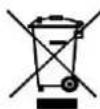
The symbol on the product or on its packaging indicates that this product may not be treated as household waste. Instead it shall be handed over to the applicable collection point for the recycling of electrical and electronic equipment. By ensuring this product is disposed of correctly, you will help prevent potential negative consequences for the environment and human health, which could otherwise be caused by inappropriate waste handling of this product. For more detailed information about recycling of this product, please contact your local city office, your household waste disposal service or the shop where you purchased the product.
CANDY
PVU 640 C
PVU 640 X
PVU 647 X
PVU 647 N
FUNP 610 X
FUNP 611 X
FUHP 615 X
FUHP 825 X
FUS 100-40 W
FUS 100-40 X
natural_image
Line drawing of three rectangular electronic enclosures with circular holes, one partially filled and one outlined (no text or symbols)DE
Lieber Kunde!
text_image
Labeled diagram of an oven with numbered parts for identificationHAUPTKOMPONENTEN
text_image
Technical diagram of a four-cylinder heating element with numbered components and directional arrows indicating flow or movement.natural_image
Line drawing of a standard oven with four control knobs and a door (no text or symbols)text_image
Cropped image showing multiple analog dials with numerical readings and control symbols, likely from a digital instrument or device.FUNP 611 X
DE
text_image
Circuit diagram with labeled components and switches, showing various ranges and connectionsFUHP 615 X
text_image
Circuit diagram with labeled components and switches, showing various connection points and valuesFUHP 825 X
DE
4.2 KOCHPLATTEN VERWENDEN:
natural_image
Diagram of a food storage or processing unit with two food containers and a tray, labeled 'Abbildung 6' (no text or symbols on the diagram itself)text_image
188°:88 - MODE +text_image
Labeled diagram of an oven with numbered parts for identificationKYPIA MEPH
text_image
Technical diagram of a multi-layered electrical or electronic component with numbered parts and labeled features.text_image
Technical diagram of a multi-layered electronic device with numbered components and mounting holesnatural_image
Line drawing of a standard open oven with control knobs and a blank front panel (no text or symbols)text_image
Circuit diagram with labeled components and voltage measurements, showing switches, resistors, and connectionstext_image
Circuit diagram with labeled components and measurement ranges, including voltage source, resistors, and terminal connectionsFUHP 615 X

text_image
Cropped image showing multiple rotary dial indicators with labeled values and symbols, likely from a control panel or meter set.FUHP 825 X
EL
natural_image
Diagram of a food storage or processing unit with two sponges inside, labeled 'Eikóva 6' at bottom (no other text or symbols)natural_image
Line drawing of three rectangular electronic enclosures with circular holes, one partially filled and one open, against a plain background (no text or symbols)ES
Estimado cliente,
text_image
Labeled diagram of an oven with numbered parts for identificationPARTES PRINCIPALES
text_image
Technical diagram of a multi-layered electronic component with labeled parts 1 through 5text_image
Technical diagram of a multi-layered electronic device with numbered components and mounting holes1 ∅ Zona destacada 145(1200W)
2 ∅ Zona dual destacada 180(1700W)
3 Zona destacada expansible (1800W)
4 Superficie de vitrocerámica
5 Revestimiento inferior
6 Indicador de hornalla caliente
natural_image
Line drawing of a standard open oven with four control knobs and a front panel (no text or symbols)text_image
Cropped image of a rotary dial with measurement scales and control buttons, showing various ranges and symbols.FUNP 610 X
text_image
Cropped image of a set of analog dials with numerical readings and control buttons, likely from an electronic device.FUNP 611 X
ES
text_image
Circuit diagram with labeled components and switches, showing various component values and connectionsFUHP 615 X
text_image
Control panel interface with rotary dials and display indicators, showing various settings for voltage or current measurement.FUHP 825 X