
EB-Z10005U - Video projector EPSON - Free user manual and instructions
Find the device manual for free EB-Z10005U EPSON in PDF.


| Product Type | Video Projector |
| Brand | Epson |
| Model | EB-Z10005U |
| Display Technology | 3LCD, 1.03-inch C2 Fine |
| Resolution | WUXGA (1920 x 1200) |
| Brightness | 10,000 lumens (Color Light Output) |
| Contrast Ratio | Up to 10,000,000:1 (dynamic) |
| Light Source | Laser diode, 20,000 hours typical |
| Lens | Powered zoom, focus, shift (interchangeable) |
| Dimensions (W x D x H) | Approx. 590 x 530 x 260 mm |
| Weight | Approx. 28.5 kg |
| Power Consumption | Normal: 1,080 W, Standby: 0.5 W |
| Input Terminals | HDMI x2, DVI-D, VGA, 5-BNC, Composite, Audio |
| Network Connectivity | Ethernet (RJ-45), RS-232C, USB |
| Operating Noise | 37 dB (Normal), 30 dB (Eco) |
| Key Features | Edge blending, 360-degree installation, HDBaseT, multi-screen projection |
| Maintenance | Filter cleaning every 2,000 hours; laser module replacement by qualified technician |
| Safety | Class 1 laser product, overheating protection, Kensington lock slot |
| Spare Parts & Repairability | Laser light source, main board, lens available; serviceable by authorized Epson technicians |
Frequently Asked Questions - EB-Z10005U EPSON
User questions about EB-Z10005U EPSON
0 question about this device. Answer the ones you know or ask your own.
Ask a new question about this device
Download the instructions for your Video projector in PDF format for free! Find your manual EB-Z10005U - EPSON and take your electronic device back in hand. On this page are published all the documents necessary for the use of your device. EB-Z10005U by EPSON.
USER MANUAL EB-Z10005U EPSON
Notations Used in This Guide
- Safety indications
The documentation and the projector use graphical symbols to show how to use the projector safely. Please understand and respect these caution symbols in order to avoid injury to persons or property.
| Warning | This symbol indicates information that, if ignored, could possibly result in personal injury or even death due to incorrect handling. |
| Caution | This symbol indicates information that, if ignored, could possibly result in personal injury or physical damage due to incorrect handling. |
- General information indications
| Attention | Indicates procedures which may result in damage or injury if sufficient care is not taken. |
| [TSC3] | Indicates additional information and points which may be useful to know regarding a topic. |
| Indicates a page where detailed information regarding a topic can be found. | |
| [IMAGE] | Indicates that an explanation of the underlined word or words in front of this symbol appears in the glossary of terms. See the "Glossary" section of the "Appendix". p.183 |
 | Indicates operating methods and the order of operations.The procedure indicated should be carried out in the order of the numbered steps. |
| [(Name)] Indicates the name of the buttons on the Remote Control or the Control panel.Example: [ESC] button | |
| "(Menu Name)"Brightness (Boldface) | Indicates the configuration menu items.Example:Select "Brightness" from the Image menu.Image menu - Brightness |
• Screen shots of the configuration menu
The screen shots may be different from those shown in this manual depending on your projector model.
Contents

Notations Used in This Guide 2
Introduction
Projector Features ....Selecting the Projection Quality (Selecting Color Mode) .... 28
Ease of Use when Installed on a Ceiling Mount....
Reliability You can Depend on
Meets a Wide Range of Needs
Enhanced Security Functions
Easy to Handle
Monitoring and Control Functions
Taking Full Advantage of a Network Connection
Part Names and Functions .... Restrictions during Split Screen Projection....
Front/Top....11
Rear 12
Interface
Control Panel
Remote Control
Installing the batteries.
Operating range of remote control
Projecting images from a computer....
Changing the Aspect Mode (EB-Z10005/Z10000/Z8150) 25
Projecting images from video equipment
Projecting images from the HDMI1/2 input port
Projecting images from a computer.
Selecting the Projection Quality (Selecting Color Mode) ..... 28
Projecting Two Images Simultaneously (Split Screen) ..... 29
Input Sources for Split Screen Projection....
Operating Procedures
Projecting on a splitscreen
Switching the left and right screens
Switching the left and right imagesizes
Ending the splitscreen
Restrictions during Split Screen Projection
Operating restrictions
Restriction relating to images
Functions for Enhancing Projection 33
Hiding the lmage Temporarily (Shutter)
Freezing the lmage (Freeze)
Pointer _1 Function (Pointer)
Enlarging Part of the Image (E-Zoom)
Saving a User's Logo 36
Security Functions 38
Managing Users (Password Protect)
Type of Password Protect
Setting Password Protect
Entering the Password
Restricting Button Operation
22 Control Panel Lock 4
Lens Operation Lock....4
Remote control button lock
Anti-Theft Lock 43
·Installing the wirelock
Memory Function 44
Contents

Available Settings....Info4Menu (Display Only) .... 77
Saving/Loading/Erasing the Memory....44
Saving the memory......Res
Loading the memory....45
Erasing the memory 45
Renaming the memory....Irau
Configuration Menu
Using the Configuration Menu 47
Configuration Menu....
Network Menu 4
Image Menu 51
Signal Menu 53
Settings Menu 55
Extended Menu 57
Network Menu 60
Notes on Operating the Network Menu....Cleaning 6.1....98
Soft Keyboard Operations....Cleaning the Projector's Surface....
Basic Menu 62 Cleaning the Lens 9
Wireless LAN Menu....€3 leaning the Air Filter....
Search Access Point screen....65
Security Menu (Only Available when the Optional Wireless LAN Unit Is Installed) Replacing Consumables 101
66 Replacing the Lamps....1
When WPA/WPA2-PSK is selected....Lamp7 replacement period....
When WPA/WPA2-EAP is selected....How to replace the lamp.
Wired LAN Menu 70 Resetting the Lamp Hours
Administrator Settings Menu....7.1ng the Air Filter
Mail Notification menu....7i3 filter replacement period
Manage Certificates menu....How ^7,4 to replace the air filter
SNMP menu 75
Reset Menu....7 6 Notes on Transportation....106
Moving Nearby 106
Contents

When Transporting
Preparing packaging
Notes when packing and transporting
Network Functions
106
Projecting with "Connect to a Network Projector" .....
Making a WPS (Wi-Fi Protected Setup) Connection with a
Wireless LAN Access Point 125
Monitoring and Controls
Connection Setup Method
Making a connection using the push button method 126
EasyMP Monitor 108
trof1)....109 Making a connection using the PIN Code Method....
Changing Settings Using a Web Browser (Web Control) ^M ^a ^k ^l ^n ^o ^p
Displaying Web Control
Displaying Web Remote.
Displaying Lens Control
Setting Certificates
Secure HTTP Notes
Installation and Connections
1 1
Installation Methods 130
Using the Mail Notification Function to Report Problems ..... 113
Reading Problem Mail Notification Function
Connecting to Video Equipment 132
Connecting to a Computer
Changing the video output from a laptop computer. 133
Management Using SNMP 1
114 connecting to Video Equipment....
ESC/VP21 Commands 1
Adjusting the Projected Image 137
Serial Connection
Communications Protocol
Command List
Displaying a Test Pattern
Adjusting the Position of the Projected Image (Lens Shift) 138
1 1 Adjusting the Tilt of the Projected Image....
About PJLink 117
Correcting Distortion in the Projected Image
Quick Corner 140
H/V-Keystone 142
Arc Correction 143
About Crestron RoomView ^® 118
Operating a Projector from a Computer Window
Displaying the operation window
Using the operation window
Using the tools window.
Adjusting the Image Quality 14
Hue ^1 , Saturation, and Brightness Adjustment
Gamma Adjustment 14
Select and adjust the correction value
Adjust while viewing the image
Adjust using the gamma adjustment graph
Frame Interpolation (EB-Z8455WU/Z8450WU only)
Super-resolution
Noise Reduction.... 14
Contents

Noise Reduction
Mosquito NR
Appendix
Settings for Multiple Project or s 150
Preparation Flow
ProjectorID/RemoteControlID
Setting the projector ID
Checking the Projector ID
Setting theremotecontrolID
Adjusting the Position of the Projected Image
Point Correction
Checking the Color Mode
Using the Edge Blending Function
Adjusting to Match Colorson Multi-Projection
Displays the Image Partly Enlarged (Scale)
Optional Accessories and Consumables 170
⑤ optional Accessories
C o.n.s.u1n5 0 b l e s
170
Screen Size and Projection Distance 171
Projection Distance of EB-Z8455WU/Z8450WU 171
Projection Distance of EB-Z8355W/Z8350W....172
Projection Distance of EB-Z10005/Z10000/Z8150 173
Supported Monitor Displays 17
Supported Monitor Displays
Computer signals (analog RGB)
Component Video
17
Composite Video/S-Video
Setting Schedule 159
Setting Methods
Clock
Daylight Saving Timescreen
Schedule
Clock / Schedule Settings screen
15gInput signals from HDMI 1/2 input port
Input signals from SDI input port (EB-Z8455WU/Z8450WU only) 176
Supported Certificates 17
Specifications 178
Projector General Specifications
Connecting to External Equipment 161
Connecting a LAN Cable
Connecting to an External Monitor
Appearance 182
Glossary 161
2.1.1.1.
General Notes 185
2 About Notations.... 18:
3 General Notice....185
Installing Optional and Supplied Accessories .... 1
Removing and Attaching the Projector Lens Unit.
Removing
Attaching
Installing the Wireless LAN Unit (ELPAP07)
Attaching
Reading the wireless LAN indicators
Attaching and Removing the Interface Cover
Removing 166
Attaching 167
Removing the Feet....168
Index 165 187

Introduction
This chapter explains the projector's features and the part names.
Ease of Use when Installed on a Ceiling Mount
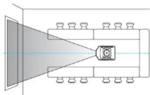
Centered lens
The lens is positioned in the center of the projector so it is well balanced and is easy to mount on a ceiling. This also makes it easy to line up the screen and the projector.
natural_image
Diagram of a room layout with furniture and a central object (no text or symbols)Equipped with electric lens shift, zoom and focus functions
Using the lens shift function that allows you to adjust the position of the projected image along the horizontal and vertical axis opens up a wide variety of installation locations.
p.138
The lens shift, zoom, and focus functions can be operated with a remote control so operation is easy even if the projector is mounted on the ceiling.
Variety of optional lenses available
You can select the best lens according to the projection distance and purpose. The bayonet type allows you to simply and easily exchange and install the optional lenses.
p.162
Various angles of projection
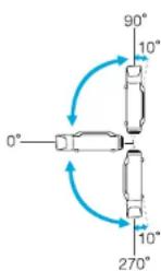
The projector can be pointed up, down, or angled to project images on the ceiling or floor, in addition to normal horizontal projection. This makes it an effective communication tool that lets you express your ideas with great impact. p.130
A design that harmonizes with the surrounding environment, and makes the installation easy
The projector's sophisticated design has a cable cover in which cables are hidden for a clean exterior appearance.
The bar type handles are designed to make moving and installing the projector easy so it can be handled safely. The ceiling mount is attached to these handles to mount the projector on the ceiling. The projector does not need to be turned upside down so installation is easy. The initial settings can be easily set as you look at the screen because the control panel is arranged on the back of the projector.
Easy maintenance
You can replace the lamp by opening a cover and pulling it straight out of the back of the projector without using a screwdriver.
There is only one air filter so cleaning and replacement are easy. The lamp and air filter can be safely replaced even when mounted on the ceiling because their covers do not fall off even if you release them.
Reliability You can Depend on
Dual lamps, to reduce risk of shutdown
The projector is equipped with two lamps. Even if one of the lamps breaks, you can continue projecting with the other lamp and avoid disrupting important presentations.
Achieves operating temperature of 0–50°C
Special coolant and fan in cooling system work against a high temperature environment during operation and improve reliability in normal use.
It depends on settings and usage environment, but you can use this projector in a place up 50°C.
Meets a Wide Range of Needs
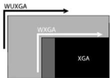
Equipped with a high-resolution WUXGA panel (EB-Z8455WU/Z8450WU only)
Projector Features

You can project a dramatic amount of information on the screen. Viewers can see the information at a glance without having to scroll or switch screens.
The frame interpolation function smoothly plays fast moving video, such as sports and action movies, reducing afterimage.
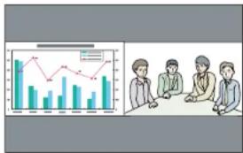
Project two images simultaneously (Split Screen)
You can simultaneously project the images from two video sources lined up on the screen. This increases the range of applications, such as when holding a video conference while projecting presentation materials. p.29
Clearly reproduce medical images
A color mode called "DICOM SIM" is provided to project medical images, such as X-ray photographs. This mode produces image quality that approaches the DICOM standard.
(The projector is not a medical device and cannot be used for medical diagnosis.) p.28
Epson Cinema Filter supports the color gamut for digital cinema.
Select Theatre or sRGB in Color Mode to use Epson Cinema Filter. When Color Mode is set to Theatre, 100% reproduction of the color gamut used for digital cinema is possible. As a result, this reproduces colors that are full and deep.
Precise color adjustments
As well as Color Mode, you can also adjust the image's absolute color temperature and the strength of each RGB color. Also, because you can adjust the hue, saturation, and brightness of each RGBCMY, the image can be projected with depth and a color matching in superior detail.
The setting values of adjusted image can be saved in memory and used when needed. If you use one projector in several places, you can easily use the previous settings again.
Seamlessly project multiple images together
When projecting on one screen from multiple projectors, color tone differences between each projected image can be adjusted to create a seamless screen, using Multiscreen and Edge Blending. p.150
Enhanced Security Functions
Password Protect to restrict and manage users
By setting a password you can restrict who can use the projector. p.38
Control Panel Lock restricts button operation on the control panel
You can use this to prevent people changing projector settings without permission at events, in schools, and so on. p.40
Equipped with various anti-theft devices
The projector is equipped with the following types of anti-theft security devices.
p.43
- Security slot
• Security cable installation point
Easy to Handle
Direct power On/Off
Projector Features

In places where power is managed centrally, such as in a conference room, the projector can be set to power on and off automatically when the power source to which the projector is connected is switched on or off.
No cool down delay
After turning the projector's power off, you can disconnect the projector's power cable without having to wait for the projector to cool down.
Monitoring and Control Functions
Schedule
You can schedule turning the projector power on/off and switching the input source, as events in the schedule. Registered events are executed automatically at the specified time on the specified dates weekly. "Setting Schedule" p.159
Supporting various protocols
A selection of monitoring and control protocols is supported, such as the Epson EasyMP Monitor application software. This allows you to use the projector according to your system environment. "Monitoring and Controls" p.107
Taking Full Advantage of a Network Connection
Simultaneously project four images for dynamic conferences
By using the EasyMP Multi PC Projection application software included, you can select up to 4 images from up to 32 computers that are connected to the network, and divide the projector's screen to show them together. Anyone can freely and easily project images from connected computers to make conferences and meetings more lively.
EasyMP Multi PC Projection Operation Guide
Transferring images using the network
The supplied EasyMP Network Projection applications software can be used to connect to network computers and transfer video and movies. Using a variety of transfer functions increases presentation possibilities. 📄 EasyMP Network Projection Operation Guide
* This unit cannot transfer audio.
Project using "Connect to a Network Projector"
By connecting the projector to a network and using the Network Projector function in Windows Vista or Windows 7, multiple users on the network can share the projector.
p.124
Front/Top
The illustration shows the projector with a standard zoom lens installed.
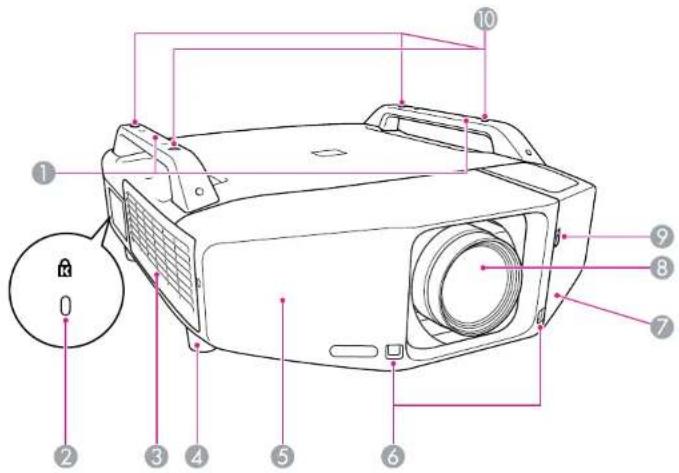
| Name Function | ||
| 1 | Handle | Use these handles when carrying the projector. Also, you can pass an anti-theft wire lock through the handles to secure the projector. p.43[8083]CautionDo not carry the projector by one person.Two people are needed to unpack or carry the projector. |
Caution
| Name Function | ||
| 2 | Security slot(8) | The Security slot is compatible with the Microsaver Security System manufactured by Kensington. p.43 |
| 3 | Air intake vent (Air filter) | Takes in air to cool the projector internally. If dust collects here it can cause the internal temperature to rise, and this can lead to problems with operation and shorten the optical engine's service life. Be sure to clean the air filter regularly. p.98, p.104 |
| 4 | Front adjustable foot | When set up on a desk, turn to extend and retract to adjust the horizontal tilt.The front adjustable feet can be removed when the projector is installed on a ceiling. p.168 |
| 5 | Front cover | Remove this cover to remove or install the lens unit when replacing the lens. p.162This cover must be installed when using the projector. |
| 6 | Remote Receiver | Receives signals from the remote control. p.18 |
| 7 | Interface cover | Remove this cover to connect cables to the ports inside when connecting the projector to video equipment. p.13, p.166 |
| 8 | Projection lens | Images are projected through here. |
| 9 | Interface cover open/ close switch | Opens and closes the interface cover. p.166 |
| 10 | Ceiling mount fixing points (Four points) | Attach the optional Ceiling mount here when suspending the projector from a ceiling. p.130, p.170 |
Rear
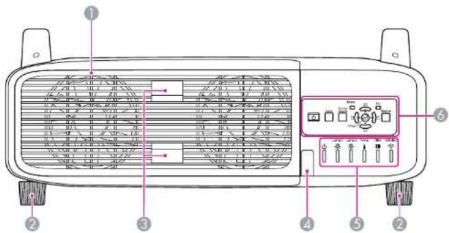
| Name Function | ||
| 1 | Air exhaust vent(Lamp cover) | Exhaust vent for air used to cool the projector internally.Also, open this cover to replace the projector's lamps. |
| CautionDo not place objects that may become warped or otherwise affected by heat near the Air exhaust vent and do not put your face or hands near the vent while projection is in progress. | ||
| 2 | Rear foot | When set up on a desk, turn to extend and retract to adjust the horizontal tilt.The rear adjustable feet can be removed when the projector is installed on a ceiling. p.168 |
| 3 | Lamp cover open tab | Use these tabs to open the lamp cover. p.101 |
| 4 | Remote Receiver | Receives signals from the remote control. p.18 |
| 5 | Status indicators | The color of the indicators and whether they are flashing or lit indicate the status of the projector. p.83 |
| Name Function | ||
| 6 | Control Panel | “Control Panel” p.14 |
Interface
The following ports can be accessed by removing the interface cover. information on how to remove the interface cover and connect video equipment, "Attaching and Removing the Interface Cover" p.166, "Connecting to Video Equipment" p.132
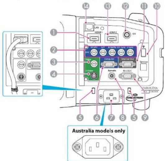
| Name Function | ||
| 1 | HDMI1 input port | Inputs video signals from HDMI compatible video equipment and computers. This projector is compatible with HDCP ^ signals. |
| 2 | BNC input port | For analog RGB signals from a computer and component video signals from other video sources. |
| Name Function | ||
| 3 | Video input port | For composite video signals from video sources. |
| 4 | S-Video input port | For S-video signals from video sources. |
| 5 | Cable holder | Connection may become defective when a thick heavy HDMI cable is connected to the HDMI input port. Run a commercially available cable tie through this holder to prevent the cable from disconnecting. |
| 6 | Computer input port | For analog RGB signals from a computer and component video signals from other video sources. |
| 7 | Power inlet | Connects to the power cable.The shape may differ depending on your projector model. |
| 8 | Remote port | Connects the optional remote control cable set and inputs signals from the remote control. When the remote control cable is plugged into this port, the remote receiver on the projector is disabled. |
| 9 | RS-232C port | When controlling the projector from a computer, connect it to the computer with an RS-232C cable. This port is for control use and should not normally be used. p.115 |
| 10 | Wireless LAN Unit port | Connects to the optional wireless LAN unit. p.165 |
| 11 | Monitor Out port | Outputs to an external monitor the analog signal from the computer connected to the Computer input port or the BNC input port. This is not available for component video signals or other signals being input to any port other than the Computer input port or the BNC input port.p.161 |
| 12 | SDI port(EB-Z8455WU/Z8450WU only) | Inputs SDI signals from a video equipment. |
| 13 | HDMI2 input port | Inputs video signals from HDMI compatible video equipment and computers. This projector is compatible with HDCP signals. |
| 14 | LAN port | Connects a LAN cable to connect to a network.p.161 |
Control Panel
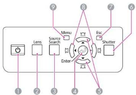
flowchart
graph TD
    A["Power"] --> B["Lens"]
    B --> C["Source Search"]
    C --> D["Menu"]
    D --> E["Enter"]
    E --> F["Shutter"]
    F --> G["Esc"]
    G --> H["9"]
    H --> I["8"]
    I --> J["7"]
    J --> K["6"]
    K --> L["5"]
    L --> M["4"]
    M --> N["3"]
    N --> O["2"]
    O --> P["1"]
| Name Function | ||
| 1 | [∅] button | Turns the projector power On or Off. ➕ Quick Start Guide |
| 2 | [Lens] button | Press this button to cycle through the focus, zoom, and lens shift settings to adjust the lens. ➕ p.138, Quick Start Guide |
| 3 | [Source Search] button | Changes to the next input source that is connected to the projector and is sending an image. ➕ p.20 |
| 4 | [Enter] button | If pressed during projection of computer analog RGB signals, it automatically adjusts the Tracking, Sync., and Position to project the optimum image.When the configuration menu or a Help screen is displayed, it accepts and enters the current selection and moves to the next level. ➕ p.47 |
| Name Function | ||
| 5 | [□/][□/] ▼button | Corrects vertical keystone distortion. p.142If pressed while the configuration menu or a Help screen is displayed, these buttons only have the [▲] and [▼functions which select menu items and setting values.p.47When projecting using "Connect to a Network Projector", these buttons function only as [▲] and [▼buttons. |
| 6 | [Shutter] button | Closes or opens the electric shutter, or mutes the image temporarily to dim the screen.Any operation that is selected in Shutter Button is executed.p.33 |
| 7 | [Esc] button | Stops the current function.If pressed when the configuration menu is displayed, it moves to the previous menu level. p.47 |
| 8 | [◇/◇][◇/◇] button | Corrects horizontal keystone distortion. p.142If pressed while the configuration menu or a Help screen is displayed, these buttons only have the [◇] and [▼functions which select menu items and setting values.p.47When projecting using "Connect to a Network Projector", these buttons function only as [◇] and [▼buttons. |
| 9 | [Menu] button | Displays and closes the configuration menu.p.47 |
Remote Control
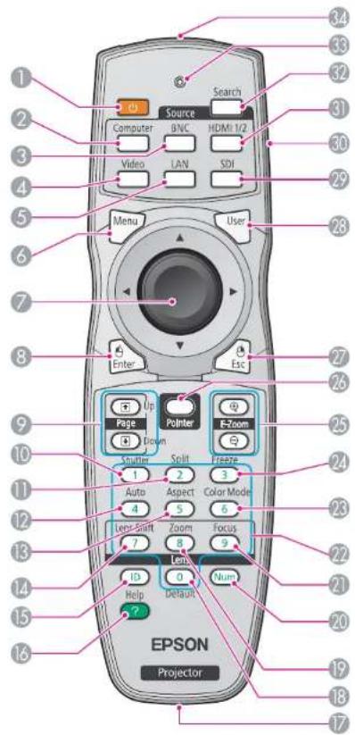
| Name Function | ||
| 1 | [∅] button | Turns the projector power On or Off. ➕ Quick Start Guide |
| 2 | [Computer] button | Changes to images from the Computer input port. ➕ p.21 |
| 3 | [BNC] button | Changes to images from the BNC input port. ➕ p.21 |
| 4 | [Video] button | Each time the button is pressed, the image displayed changes between the Video input port and S-Video input port. ➕ p.21 |
| 5 | [LAN] button | Changes to images of EasyMP Network Projection. ➕ p.21 |
| 6 | [Menu] button | Displays and closes the configuration menu. ➕ p.47 |
| 7 | [∅] button | When the configuration menu or Help screen is displayed, it selects menu items and setting values. ➕ p.47, p.81When using the optional wireless mouse receiver, tilting this button moves the pointer in the direction (eight possible directions) tilted. |
| 8 | [Enter] button | When the configuration menu or a Help screen is displayed, it accepts and enters the current selection and moves to the next level. ➕ p.47, p.81Acts as a mouse's left button when using the optional wireless mouse receiver. |
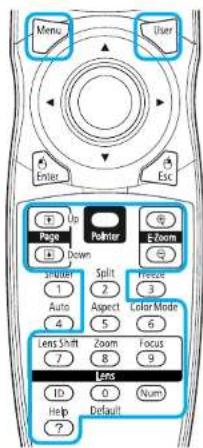
| 9 | [Page] buttons [+] [+] | When using the optional wireless mouse receiver, you can change the PowerPoint file page during projection by pressing the page up/page down buttons. |
| 10 | [Shutter] button | Closes or opens the electric shutter, or mutes the image temporarily to dim the screen.Any operation that is selected in Shutter Button is executed. ➕ p.33 |
| 11 | [Split] button | Press this button to split the screen in two and project two images simultaneously. ➕ p.29 |
| 12 | [Auto] button | If pressed during projection of computer analog RGB signals, it automatically adjusts the Tracking, Sync., and Position to project the optimum image. |
| 13 | [Aspect] button | The Aspect Ratio changes each time the button is pressed. p.22 |
| 14 | [Lens Shift] button | Press to adjust the lens shift. p.138 |
| 15 | [ID] button | Press to set the remote control ID. p.150 |
| 16 | [Help] button | Displays and closes the Help screen which shows you how to deal with problems if they occur. p.81 |
| 17 | Remote port | Connects the optional remote control cable set and outputs signals from the remote control. When the remote control cable is plugged into this remote port, the remote receiver is disabled. |
| 18 | [Default] button | Reset to default the setting values being adjusted in some configuration menus. |
| 19 | [Zoom] button | Press to adjust the zoom. Quick Start Guide |
| 20 | [Num] button | Use this button to enter passwords, IP Address from the Network, and so on. p.38 |
| 21 | [Focus] button | Press to adjust the focus. We recommend setting the focus, zoom, and lens shift at least 30 minutes after you start the projection, because images are not stable right after turning on the projector. Quick Start Guide |
| 22 | Numeric buttons | Use this button to enter passwords, remote control ID settings, IP Address from the Network, and so on. p.152, p.38 |
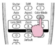
| 23 | [Color Mode] button | Each time the button is pressed, the Color Mode changes. p.28 |
| 24 | [Freeze] button | Images are paused or unpaused. p.33 |
| 25 | [E-Zoom] buttons [+] [⊖] | The [⊕] button enlarges the image without changing the projection size.The [⊖] button reduces the parts of images that have been enlarged using the [⊕] button. p.34 |
| Name Function | ||
| 26 | [Pointer] button | Press to activate the on screen pointer. p.34 |
| 27 | [Esc] button | Stops the current function. If pressed when the configuration menu is displayed, it moves to the previous menu level. p.47Acts as a mouse's right button when using the optional wireless mouse receiver. |
| 28 | [User] button | Press to assign a frequently used item from the available configuration menu items. By pressing the button the assigned menu item selection/adjustment screen is displayed, allowing you to make one-touch settings/adjustments. p.55Test Pattern is assigned as the default setting. |
| 29 | [SDI] button | Changes to images from the SDI input port. p.21This button does not function when using EB-Z8355W/Z8350W/Z10005/Z10000/Z8150. |
| 30 | ID switch | Use this switch to enable (On)/disable (Off) ID settings for the remote control. p.150 |
| 31 | [HDMI 1/2] button | Each time the button is pressed, the image displayed changes between the HDMI1 input port and HDMI2 input port. p.21 |
| 32 | [Search] button | Changes to the next input source that is connected to the projector and is sending an image. p.20 |
| 33 | Indicators | A light is emitted when outputting remote control signals. |
| 34 | Remote control light-emitting area | Outputs remote control signals. |
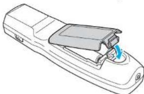
Installing the batteries
The batteries are not set in the remote control when it is sold. Set the supplied batteries (two, AA alkaline batteries) to use the remote control.
Attention
Make sure you read the Safety Instructions before handling the batteries.
Safety Instructions
Procedure

Remove the battery cover.
While pushing the battery compartment cover catch, lift the cover up.
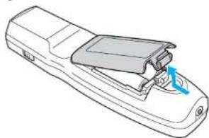
natural_image
Line drawing of a remote control box with a blue arrow indicating rotation (no text or symbols)
Insert the batteries in the correct direction.
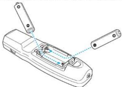
natural_image
Line drawing of a remote control device with handle and internal components (no text or symbols)
Caution
Check the positions of the (+) and (-) marks inside the battery holder to ensure the batteries are inserted the correct way.

Replace the battery cover.
Press until it clicks into place.
natural_image
Line drawing of a remote control device with handle and ventilation slots (no text or symbols)If delays in the responsiveness of the remote control occur or if it does not operate after it has been used for some time, it probably means that the batteries are becoming flat. When this happens, replace them with new batteries. Have two AA size alkaline batteries ready. You cannot use other batteries except for the AA size alkaline.
Operating range of remote control
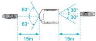
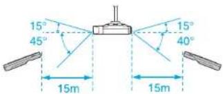
When using the remote control, point the remote control light-emitting area at the remote receiver on the projector. The operating range of the remote control that is provided with the projector is shown below.
Horizontal operating range
Vertical operating range

- To restrict reception of the operation signals from the remote control, set the Remote Receiver on the Settings menu.
p.55
- When using a remote control provided with other Epson projectors, set the Remote Control Type on the Extended menu. p.57 The operating range will depend on the remote control that you use.

Useful Functions
This chapter explains useful tips for giving presentations, and the security functions.
Changing the Projected Image

You can change the projected image in the following two ways.
- Changing by Source Search The projector automatically detects signals being input from connected equipment, and the image being input from the input port is projected.
- Changing directly to the target image You can use the remote control buttons to change to the target input port.
Automatically Detect Input Signal and Change the Projected Image (Source Search)
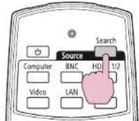
You can project the target images quickly by pressing the [Source Search] button because it will switch only to images from input ports to which image signals are being input.
Procedure
When your video equipment is connected, start playback before beginning this operation. When two or more pieces of equipment are connected, press the [Source Search] button until the target image is projected.
Using the Remote Control Using the Control Panel
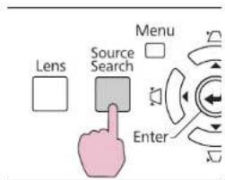
When the [Source Search] button is pressed, a search is made for input ports to which video signals are being input in the following order. (The input port where no image signal is being input is skipped.)
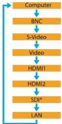
flowchart
graph TD
    A["Computer"] --> B["BNC"]
    B --> C["S-Video"]
    C --> D["Video"]
    D --> E["HDMI1"]
    E --> F["HDMI2"]
    F --> G["SDI*"]
    G --> H["LAN"]
* EB-Z8455WU/Z8450WU only
When switching to LAN, images from computers connected through the network are projected.

The following screen showing the status of image signals remains displayed when only the image that the projector is currently displaying is available, or when no image signal can be found. You can select the input port where the equipment you want to use is connected. If no operation is performed after about 10 seconds, screen closes.
![[Source Search] Computer Signal Status Off BNC Off S-Video Off V-dec Off HDMI1 Off HDMI2 Off SDI Off LAN Off Input an image signal. Press to select the source.](/content/2026/05/815375/images/c3ce60cff29befa281077fadb7449fcb91da0a1fe101089e9dc914c271bcb9e2.jpg)
* EB-Z8455WU/Z8450WU only
Switch to the Target Image by Remote Control
You can change directly to the image from the target input port by pressing the following buttons on the remote control "Remote Control" p.15
When switching to LAN, images from computers connected through the network are projected.
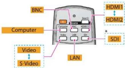
Changing the Aspect Ratio of the Projected Image

You can select the aspect mode according to the type of input signal, ratio of height and width, and resolution to switch the aspect Ratio of the projected image. The aspect modes are listed below. The aspect modes that can be set depend on the type of image that is being projected.
EB-Z8455WU/Z8450WU/Z8355W/Z8350W
| Aspect mode Explanation | |
| Normal | Projects to the full projection size retaining the aspect ratio of the input image. |
| Auto | Projects in an appropriate aspect ratio based on information from the signal being input. |
| 16:9 | Projects to the full projection size at an aspect ratio of 16:9. |
| 16:9 (Up) | Projects to the full projection size at an aspect ratio of 16:9 on the top of the screen. |
| 16:9 (Down) | Projects to the full projection size at an aspect ratio of 16:9 on the bottom of the screen. |
| Full | Projects at full size. |
| Zoom | Projects the input image enlarged to the full lateral direction size as the aspect ratio remains. Parts that extend beyond the projection size are not projected. |
| Native | Projects at the resolution of the input image size to the center of the screen. This is ideal for projecting clear images.If the image resolution exceeds the panel resolution of this projector (EB-Z8355W/Z8350W: 1280x800, EB-Z8455WU/Z8450WU: 1920x1200), the edges of the image are not projected. |
EB-Z10005/Z10000/Z8150
| Aspect mode Explanation | |
| Normal | Projects to the full projection size retaining the aspect ratio of the input image. |
| Aspect mode Explanation | |
| Auto | Projects in an appropriate aspect ratio based on information from the signal being input. |
| 4:3 | Projects to the full projection size at an aspect ratio of 4:3. This is suitable for images at an aspect ratio of 5:4 (1280x1024, etc) at full projection size. |
| 16:9 | Projects at an aspect ratio of 16:9. This is suitable for projecting to the full screen size of 16:9. |
| 16:9 (Up) | Projects to the full projection size at an aspect ratio of 16:9 on the top of the screen. |
| 16:9 (Down) | Projects to the full projection size at an aspect ratio of 16:9 on the bottom of the screen. |
| Native | Projects at the resolution of the input image size to the center of the screen. This is ideal for projecting clear images.If the image resolution exceeds the panel resolution of this projector (1024x768), the edges of the image are not projected. |
Procedure
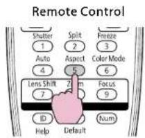
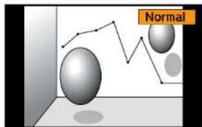
The aspect mode name is displayed on the screen by pressing the button. If you press the button while the aspect mode name is displayed on the screen, it changes to the next aspect mode.
Changing the Aspect Ratio of the Projected Image


- The aspect mode can also be set using Aspect in the Signal menu from the configuration menu. p.53
- When Scale on the Signal menu is set to On and Scale Mode is set to Full Display, you cannot change the aspect mode.
Changing the Aspect Mode (EB-Z8455WU/Z8450WU)
Projecting images from video equipment or from the HDMI1/2 or SDI input port
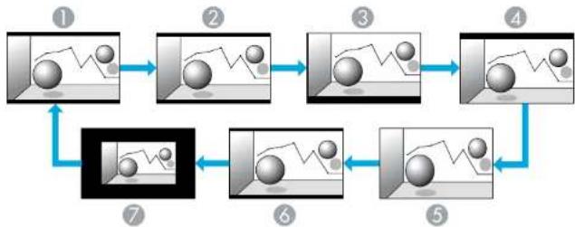
Each time the [Aspect] button on the remote control is pressed, the aspect mode changes in the order Auto (Normal when projecting from the SDI input port), 16:9, 16:9 (Up), 16:9 (Down), Full, Zoom, and Native.
p.22
Example: 720p signal input (resolution: 1280x720, aspect ratio: 16:9)
flowchart
graph TD
    A["Input Image"] --> B["Image 1"]
    B --> C["Image 2"]
    C --> D["Image 3"]
    D --> E["Image 4"]
    E --> F["Output Image"]
    F --> G["Final Output"]
    G --> H["Feedback Loop"]
    H --> I["Image 5"]
    I --> J["Image 6"]
    J --> K["Image 7"]
① Auto/Normal
② 16:9
③ 16:9 (Up)
4 16:9 (Down)
⑤ Full
6 Zoom
⑦ Native
Projecting images from a computer
Each time the [Aspect] button on the remote control is pressed, the aspect mode changes in the order Normal, 16:9, 16:9 (Up), 16:9 (Down), Full, Zoom, and Native. p.22
Projection examples for each aspect mode are shown below.
| Aspect mode Input Signal | |||
| XGA1024X768(4:3) | WXGA1280X800(16:10) | WUXGA1920X1200(16:10) | |
| Normal | 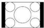 | 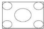 | |
| 16:9 | 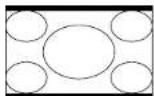 | 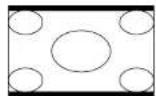 | |
| 16:9 (Up) | 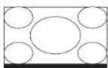 | 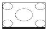 | |
| 16:9 (Down) | 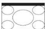 | 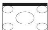 | |
Changing the Aspect Ratio of the Projected Image

| Aspect mode Input Signal | |||
| XGA1024X768(4:3) | WXGA1280X800(16:10) | WUXGA1920X1200(16:10) | |
| Full | 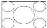 | 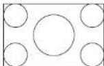 | 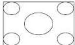 |
| Zoom | 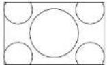 | 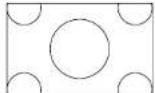 | |
| Native | 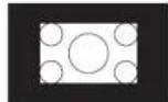 | ||

If parts of the image are missing or it cannot project everything, Wide or Normal in Resolution from the configuration menu depending on the size of the computer panel. p.53
Changing the Aspect Mode (EB-Z8355W/Z8350W)
Projecting images from video equipment or from the HDMI1/2 input port
Each time the [Aspect] button on the remote control is pressed, the aspect mode changes in the order Auto, 16:9, 16:9 (Up), 16:9 (Down), Full, Zoom, and Native. p.22
Example: 1080p signal input (resolution: 1920x1080, aspect ratio: 16:9)
flowchart
graph TD
    A["Input Image"] --> B["Image 1"]
    B --> C["Image 2"]
    C --> D["Image 3"]
    D --> E["Image 4"]
    E --> F["Output Image"]
    F --> G["Final Output"]
    G --> H["Feedback Loop"]
    H --> I["Image 5"]
    I --> J["Image 6"]
    J --> K["Image 7"]
1 Auto
② 16:9
3 16:9 (Up)
4 16:9 (Down)
Full
6 Zoom
7 Native
Projecting images from a computer
Each time the [Aspect] button on the remote control is pressed, the aspect mode changes in the order Normal, 16:9, 16:9 (Up), 16:9 (Down), Full, Zoom, and Native. p.22
Projection examples for each aspect mode are shown below.
| Aspect mode Input Signal | |||
| XGA1024X768(4:3) | WXGA1280X800(16:10) | SXGA1280X1024(5:4) | |
| Normal | 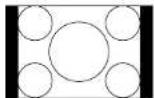 | 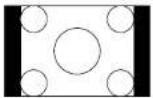 | |
Changing the Aspect Ratio of the Projected Image

| Aspect mode Input Signal | |||
| XGA1024X768(4:3) | WXGA1280X800(16:10) | SXGA1280X1024(5:4) | |
| 16:9 | 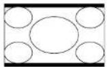 | 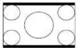 | 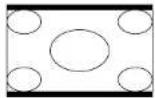 |
| 16:9 (Up) | 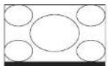 | 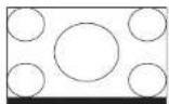 | 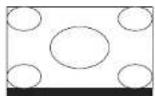 |
| 16:9 (Down) | 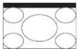 | 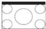 | 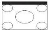 |
| Full | 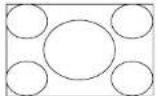 |  | 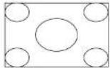 |
| Zoom | 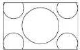 | 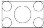 |  |
| Native |  | ||
Changing the Aspect Mode (EB-Z10005/Z10000/Z8150)
Projecting images from video equipment
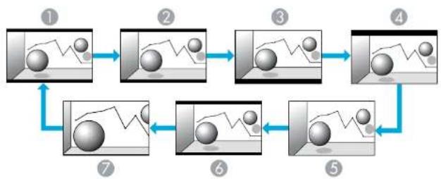
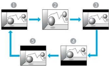
Each time the |Aspect| button on the remote control is pressed, the aspect mode changes in the order Auto, 4:3, 16:9, 16:9 (Up), and 16:9 (Down). p.22
When inputting a 720p/1080i/1080p signal and the aspect mode is set to 4:3, a 4:3 zoom will be applied (the right and left sides of the image will be cut off).
Example: 720p signal input (resolution: 1280x720, aspect ratio: 16:9)
flowchart
graph TD
    A["Step 1: Initial image with fluctuating sphere"] --> B["Step 2: Initial image with spherical particles"]
    B --> C["Step 3: Initial image with fluctuating sphere"]
    C --> D["Step 4: Initial image with spherical particles"]
    D --> E["Step 5: Final image with wavy line"]
    E --> A
1 Auto
② 4:3
③ 16:9
4 16:9 (Up)
⑤ 16:9 (Down)

If parts of the image are missing or it cannot project everything, set Wide or Normal in Resolution from the configuration menu depending on the size of the computer panel. p.53
Changing the Aspect Ratio of the Projected Image

Projecting images from the HDMI1/2 input port
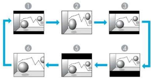
Each time the [Aspect] button on the remote control is pressed, the aspect mode changes in the order Auto, 4:3, 16:9, 16:9 (Up), 16:9 (Down), and Native. p.22
Example: 1080p signal input (resolution: 1920x1080, aspect ratio: 16:9)
flowchart
graph TD
    A["Step ①: Object tracking"] --> B["Step ②: Object movement"]
    B --> C["Step ③: Object trajectory"]
    C --> D["Step ④: Object movement"]
    D --> E["Step ⑤: Object movement"]
    E --> F["Step ⑥: Object tracking"]
    F --> A
① Auto
② 4:3
③ 16:9
4 16:9 (Up)
⑤ 16:9 (Down)
6 Native
Projecting images from a computer
Each time the [Aspect] button on the remote control is pressed, the aspect mode changes in the order Normal, 4:3, 16:9, 16:9 (Up), 16:9 (Down), and Native. p.22
Projection examples for each aspect mode are shown below.
| Aspect mode Input Signal | |||
| XGA1024X768(4:3) | WXGA1280X800(16:10) | SXGA1280X1024(5:4) | |
| Normal | |||
| 4:3 | |||
| 16:9 | |||
| 16:9 (Up) | |||
| 16:9 (Down) | |||
| Native | |||
Changing the Aspect Ratio of the Projected Image


If parts of the image are missing or it cannot project everything, set Wide or Normal in Resolution from the configuration menu depending on the size of the computer panel. p.53
Selecting the Projection Quality (Selecting Color Mode)

You can easily obtain the optimum image quality simply by selecting the setting that best corresponds to your surroundings when projecting. The brightness of the image varies depending on the mode selected.
| Mode Application | |
| Dynamic | Ideal for use in a bright room. This is the brightest mode. |
| Presentation | Ideal for making presentations using color materials in a bright room. |
| Theatre | Ideal for watching films in a dark room. Gives images a natural tone almost like an original source. |
| Photo^*1 | Ideal for projecting still pictures, such as photos, in a bright room. The images are vivid and brought into contrast. |
| Sports^*2 | Ideal for watching TV programmes in a bright room. The images are vivid and brought to life. |
| sRGB | Ideal for images that conform to thRGB color standard. |
| DICOM SIM ^1 | Ideal for projecting X-ray photographs and other medical images. This produces images with clear shadows.The projector is not a medical device and cannot be used for medical diagnosis. |
| Multi-Projection | Ideal for projecting from multiple projectors.Minimize the color tone difference between each projected image. |
*1 This can be selected when inputting RGB signals, or when LAN is selected as the input source.
*2 This can be selected when inputting component video signals, S-video signals, or composite video signals.
Procedure
Remote Control
bar
| Category | Value | |---|---| | Bar 1 | 3.5 | | Bar 2 | 1.8 | | Bar 3 | 4.2 | | Bar 4 | 5.0 | Legend: PresentationThe Color Mode name is displayed on the screen by pressing the button.
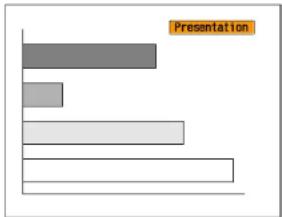
If you press the button while the Color Mode name is displayed on the screen, it changes to the next Color Mode.

The color mode can also be set using Color Mode in the Image menu from the configuration menu. p.51
Projecting Two Images Simultaneously (Split Screen)

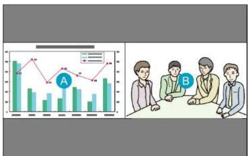
A split screen can be used to divide the screen into a left screen (A) and a right screen (B) and simultaneously project two images.
bar_line
| Category | Series 1 (Green Bars) | Series 2 (Red Line) | |---|---|---| | A | 35 | 30 | | B | 25 | 20 |Input Sources for Split Screen Projection
The combinations of input sources that can be projected on a split screen are listed below.
| Left Screen | Right Screen | |||||||
| Computer | BNC S-Video | Video HDMI 1 | HDMI 2 | LAN SDI | * | |||
| Computer | - | - | √ | √ | √ | √ | √ | √ |
| BNC -- | √ | √ | √ | √ | √ | √ | ||
| S-Video | √ | √ | - | - | √ | √ | √ | √ |
| Video - | √ - | √ | √ | √ | √ | √ | ||
| IIDMI 1 | √ | √ | √ | √ | - | - | √ | √ |
| Left Screen | Right Screen | |||||||
| Computer | BNC S-Video | Video H | DMI 1 | HDMI 2 | LAN SDI | x | ||
| HDMI 2 | √ | √ | √ | √ | - | - | √ | √ |
| LAN - | √- | √ | √ | √ | √ | √ | ||
| SDI* | √ | √ | √ | √ | √ | √ | - | - |
* EB-Z8455WU/Z8450WU only
Operating Procedures
Projecting on a split screen
Procedure

Press the [Split] button on the remote control while the projector is projecting.
The currently selected input source will be displayed on the left screen.
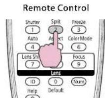

The split screen can also be started from Split Screen on the configuration menu. p.55
Projecting Two Images Simultaneously (Split Screen)


Press the [Menu] button on the remote control or the control panel.
The Split Screen Setup will be displayed.
![[Split Screen Setup] Screen Size Equal Source Swap Screens Exit Split Screen](/content/2026/05/815375/images/970b79e6cca58bc2ea7d2faf6a31a687dcf8ce972269eed64f15f0c39540d12f.jpg)

The Split Screen Setup will also be displayed when the [Source Search] button is pressed on the remote control or control panel when a Source button is pressed on the remote control.
or

Select "Source" and press the Enter button.

Select each input source for "Left" and "Right".
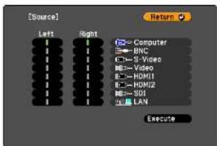
Only the input sources that can be combined can be selected. ● "Input Sources for Split Screen Projection" p.29

Select "Execute" and prses the Enter button.
To switch the projected image during split screen projection, start the procedure from step 2.

Analog RGB signals that are output from the left screen can be displayed on an external monitor. p.161
Switching the left and right screens
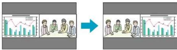
Use the following procedure to switch the images displayed on the left and right screens.
Procedure

Press the [Menu] button on the remote control or the control panel during split screen projection.

Select "Swap Screens" and press the Enter button. The images on the left and right screens will be swapped.
flowchart
graph LR
    A["Data Visualization"] --> B["Group of people reviewing reports"]
    B --> C["Report and Analysis"]
    C --> D["Final Output"]
Projecting Two Images Simultaneously (Split Screen)

Switching the left and right image sizes
Procedure

Press the [Menu] button on the remote control or the control panel during split screen projection.

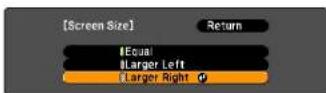
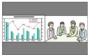
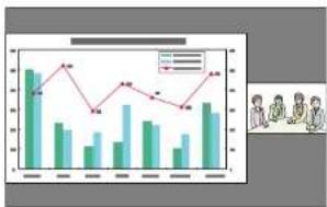
Select "Screen Size" and press the Enter button.

Select the image size to display and then press the Enter button.
Larger Right
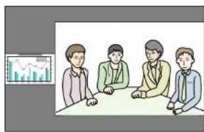

- You cannot enlarge both the left screen and right screen images at the same time.
- When one image is enlarged, the other image is reduced.
- Depending on the video signals that are input, the images on the left and right may not appear to be the same size even if Equal is set.

Press the [Menu] button to end the setting procedure.
The projected images will appear as shown below after setting the screen size.
Ending the split screen
Equal Larger Left
bar_line
| Month | Bar Value | Line Value | |---|---|---| | Jan | 100 | 80 | | Feb | 75 | 95 | | Mar | 60 | 70 | | Apr | 50 | 85 | | May | 80 | 75 | | Jun | 65 | 90 | | Jul | 40 | 80 | | Aug | 70 | 70 | | Sep | 55 | 85 | | Oct | 60 | 90 | | Nov | 75 | 85 | | Dec | 80 | 95 |Procedure
To end the split screen, press the Esc button on the remote control or control panel.
The following steps can also be used to end the split screen.
- Press the [Split] button on the remote control.
- Select Exit Split Screen in the Split Screen Setup and then press the Enter button.
Restrictions during Split Screen Projection
Operating restrictions
The following operations cannot be performed during split screen projection.
- Setting the configuration menu
• E-zoom - Switching the aspect mode (The aspect mode will be set to Normal.) p.22
- Operations using the [User] button on the remote control
- Auto Iris
Help can be displayed only when image signals are not input or when an error or warning notification is displayed.
Restriction relating to images
- The default values for the Image menu are applied to the image on the right screen. However, the settings for the image projected on the left screen are applied to the image on the right screen for the Color Mode, Abs. Color Temp., Advanced, Super-resolution, and Frame Interpolation.
- The setting value Off for Progressive and Noise Reduction is applied to the image on the right screen. Signal menu p.53
- When there is no image signal input, the display screen will be the color that is set on Display Background. The display will be Blue when the Logo is selected.
- When the shutter operation is performed, the display screen will be Black.
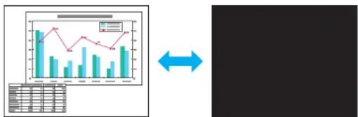
Hiding the Image Temporarily (Shutter)
You can use this when you want to focus the audience's attention on what you are saying, or if you do not want to show details such as when you are changing between files during presentations from a computer.
bar_line
| Category | Bar Value | Line Value | |---|---|---| | Bar Value 1 | 35 | 28 | | Bar Value 2 | 20 | 32 | | Bar Value 3 | 25 | 20 | | Bar Value 4 | 30 | 25 | | Bar Value 5 | 20 | 30 | | Bar Value 6 | 25 | 28 | | Bar Value 7 | 30 | 35 | | Bar Value 8 | 20 | 30 | | Bar Value 9 | 25 | 35 | | Bar Value 10 | 30 | 30 | The bottom table shows the same category '数据' (Data) for the first three categories. The top panel displays a line graph of '数据' (Data) over time, with values ranging from 15 to 35. The arrow between the bottom and right indicates a bidirectional relationship or transformation between the two series.Make sure that the Shutter Button is set to Electric Shutter from Operation in the Extended menu.
Procedure
Using the Remote Control Using the Control Panel
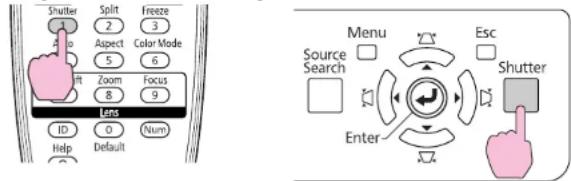
Each time you press the buttons, the electric shutter closes or opens.

- When the shutter is closed and no operations are performed for about 30 minutes, the projector enters Sleep Mode and turns off automatically. If you do not want Sleep Mode to activate, change the Shutter Timer setting to Off from Operation in the Extended menu. p.57
- If you press [⏻] button while the shutter is closed, the shutter automatically opens and a message requesting confirmation to turn off the power is displayed on the screen.
- The Lamp1 and Lamp2 indicators flash green while the shutter is activated.
- When an event that is set in Schedule is executed, the shutter is canceled.
Freezing the Image (Freeze)
When the freeze function is activated on moving images, the frozen image continues to be projected on the screen, so you can project a moving image one frame at a time like a still photo. Also, you can perform operations such as changing between files during presentations from a computer without projecting any images if the freeze function is activated beforehand.
Procedure
Remote Control

natural_image
Illustration of a hot air balloon floating above clouds (no text or symbols)Each time you press the button, Freeze turns on or off.
Functions for Enhancing Projection


- The image source continues to play back the moving images even while Freeze is on, and so it is not possible to resume projection from the point where it was paused.
- If the [Freeze] button is pressed while the configuration menu or a Help screen is displayed, the menu or Help screen being displayed is cleared.
- Freeze still works while E-Zoom is being used.
Pointer Function (Pointer)
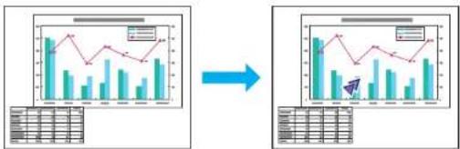
This allows you to move a Pointer icon on the projected image, and helps you draw attention to the area you are talking about.
Procedure

Display the Pointer.
Remote Control
Each time you press the button, the pointer appears or disappears.

Move the Pointer icon (7).
Remote Control

You can choose from three different kinds of Pointer icon (☑, ☑ or ▲) in Settings - Pointer Shape from the configuration menu. p.55
Enlarging Part of the Image (E-Zoom)
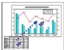
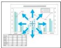
This is useful when you want to expand images to see them in greater detail, such as graphs and tables.
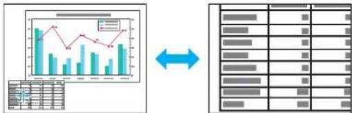
flowchart
graph LR
    A["Input Data"] --> B["Processing Graph"]
    B --> C["Output Server Rack"]
    D["Table Data"] --> B
    E["Database Server Rack"] --> C
Procedure

Start E-Zoom.
Remote Control

Move the ( ) to the area of the image that you want to enlarge.
Remote Control
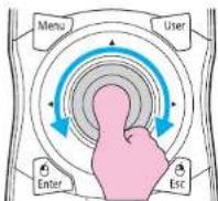

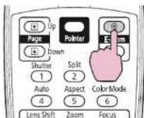
Enlarge.
Remote Control
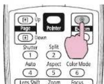
Each time the button is pressed, the area is expanded. You can expand quickly by holding the button down.
You can reduce the enlarged image by pressing the button.
Press the Esc button to cancel.

- The enlargement ratio appears on the screen. The selected area can be enlarged to between 1 to 4 times in 25 incremental steps.
• After the image is enlarged, it can be scrolled with the button. - E-Zoom is canceled when performing some functions such as keystone or Auto Setup.
- When the Scale is set to On, the E-Zoom cannot be used.
Saving a User's Logo

You can save the image that is currently being projected as a User's Logo.
The saved user's logo can be used as the display image when there is no video signal input or during starting up.

Once a User's Logo has been saved, the logo cannot be returned to the factory default.
Procedure

Project the image you want to use as the User's Logo, and then press the [Menu] button.
Using the Remote Control Using the Control Panel
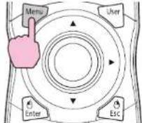
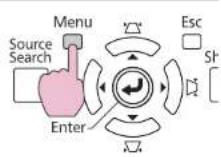

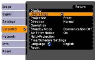
Select Extended - "User's Logo" from the configuration menu. - "Using the Configuration Menu" p.47
Check the buttons you can use and the operations they perform in the guide under the menu.

- If User's Logo Protect from Password Protect is set to On, a message is displayed and the user's logo cannot be changed. You can make changes after setting User's Logo Protect to Off.
p.38
- If User's Logo is selected when keystone, E-Zoom, or Aspect are being performed, the function currently being performed is cancelled.

When "Choose this image as the User's Logo?" is displayed, select "Yes".

When you press the Enter button on the Remote Control or the Control panel, the screen size may change according to the signal as it changes to the resolution of the image signal.

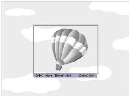
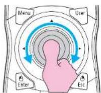
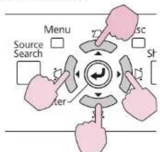
Move the box to select the part of the image to use as the User's Logo.
natural_image
Illustration of a hot air balloon on a cloudy sky background (no text or symbols)Using the Remote Control Using the Control Panel
flowchart
graph TD
    A["Source Search"] --> B["Menu"]
    B --> C["Server"]
    C --> D["Service"]
    D --> E["Shr"]

You can save at up to 400 × 300 dots in size.

When "Select this image?" is displayed, select "Yes".

Select the zoom factor from the zoom setting screen.
![[User's Logo] Set the zoom factor. Zoom factor: 100% 200% 300% 400%](/content/2026/05/815375/images/c635b725ab78a49ff30792399da8546b5b91a826f63bffaf5bf3469f3889f1df.jpg)
400% is displayed only when using EB-Z8455WU/Z8450WU.

When the message "Save this image as the User's Logo?" is displayed, select "Yes".
The image is saved. After the image has been saved, the message "Completed." is displayed.

- To use the saved user's logo as the screen image, set it in the Display settings under the Extended menu. p.57
- When a User's Logo is saved, the previous User's Logo is erased.
- Saving the user's logo may take approximately 15 seconds. Do not use the projector or any connected equipment while it is saving, otherwise malfunctions may occur.
Security Functions

The projector has the following enhanced security functions.
- Password Protect
You can limit who can use the projector. - Control Panel Lock/Lens Operation Lock/Remote control button lock You can prevent people changing the settings on the projector without permission. p.40
- Anti-Theft Lock The projector is equipped with various types of anti-theft security devices. p.43
Managing Users (Password Protect)
When Password Protect is activated, people who do not know the Password cannot use the projector to project images even if the projector power is on. Furthermore, the user's logo that is displayed when you turn on the projector cannot be changed. This acts as an anti-theft device as the projector cannot be used even if it is stolen. At the time of purchase, Password Protect is not activated.
Type of Password Protect
The following three kinds of Password Protect settings can be made according to how the projector is being used.
1. Power On Protect
When Power On Protect is On, you need to enter a preset Password after the projector is plugged in and turned on (this also applies to Direct Power On). If the correct Password is not entered, projection does not start.
2. User's Logo Protect
Even if someone tries to change the User's Logo set by the owner of the projector, it cannot be changed. When User's Logo Protect is set to On, the following setting changes for the User's Logo are prohibited.
• Capturing a User's Logo
- Settings for Display Background, and Startup Screen from Display in the configuration menu
3. Network Protect
When Network Protect is set to On, setting changes for Network menu in the configuration menu are prohibited.
Setting Password Protect
Use the following procedure to set Password Protect.
Procedure

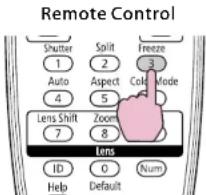
During projection, hold down the [Freeze] button for about five seconds.
The Password Protect setting menu is displayed.
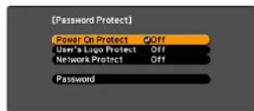

- If Password Protect is already activated, you must enter the Password. If the Password is entered correctly, the Password Protect setting menu is displayed. "Entering the Password" p.39
- When the Password is set, stick the Password protect sticker in a visible position on the projector as a further theft deterrent.

Turn on "Power On Protect".
(1) Select Power On Protect, and then press the Enter button.
(2) Select On, and then press the Enter button.
(3) Press the Esc button.

Turn on "User's Logo Protect".
(1) Select User's Logo Protect, and then press the Enter button.
(2) Select On, and then press the Enter button.
(3) Press the Esc button.

Turn on "Network Protect".
(1) Select Network Protect, and then press the Enter button.
(2) Select On, and then press the Enter button.
(3) Press the Esc button.

Set the Password.
(1) Select Password, and then press the Enter button.
(2) The message "Change the password?" is displayed, select Yes and then press the Enter button. The default setting for the Password is "0000". Change this to your own desired password. If you select No, the screen shown in step 1 is displayed again.
(3) While holding down the [Num] button, enter a four digit number using the numeric buttons. The number entered is displayed as "***". When you enter the fourth digit, the confirmation screen is displayed.
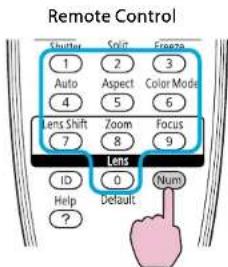
(4) Re-enter the Password.
The message "Password accepted." is displayed.
If you enter the Password incorrectly, a message is displayed prompting you to re-enter the password.
Entering the Password
When the Password entry screen is displayed, enter the Password using the numeric buttons on the remote control.
Procedure
While holding down the [Num] button, enter the Password by pressing the numeric buttons.
When you enter the correct Password, projection begins.
Attention
- If an incorrect password is entered three times in succession, the message "The projector's operation will be locked." is displayed for about five minutes, and then the projector switches to standby mode. If this happens, disconnect the power plug from the electrical outlet and then reinsert it and turn the projector's power back on. The projector displays the Password entry screen again so that you can enter the correct Password.
- If you have forgotten the password, make a note of the "Request Code: xxxxx" number that appears on the screen and contact the nearest address provided in the Support and Service Guide. Epson Projector Contact List
- If you continue to repeat the above operation and input the wrong Password thirty times in succession, the following message is displayed and the projector does not accept any more Password entries. "The projector's operation will be locked. Contact Epson as described in your documentation." - Epson Projector Contact List
Control Panel Lock
Perform one of the following to lock the operation buttons on the control panel. Even if the control panel is locked, you can still use the remote control as usual.
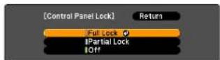
- Full Lock
All of the buttons on the control panel are locked. You cannot perform any operations from the control panel, including turning the power on or off.
- Partial Lock
All of the buttons on the Control panel, except for the button, are locked.
Restricting Button Operation
The following three kinds of operation restriction functions are available with the projector.
• Control Panel Lock
This is useful at events or shows when you want to deactivate all buttons during projection or at schools when you want to limit button operation.
- Lens Operation Lock
This function deactivates all buttons on the remote control related to the lens operation to prevent improper lens adjustment after it is properly adjusted.
- Remote control button lock
This function deactivates buttons except for main buttons needed for basic remote control operation, to prevent mistakes in operations.
Procedure

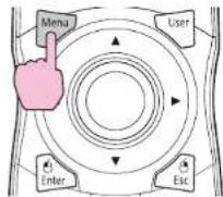
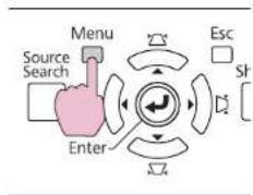
During projection, press the [Menu] button and select Settings - "Control Panel Lock" from the configuration menu. ◎ "Using the Configuration Menu" p.47
Using the Remote Control Using the Control Panel
flowchart
graph TD
    A["Menu"] --> B["Source Search"]
    B --> C["Enter"]
    C --> D["Esc"]
    D --> E["Sf"]
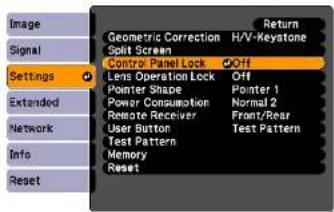

Select either "Full Lock" or "Partial Lock" according to your purpose.

Select "Yes" when the confirmation message is displayed.
The control panel buttons are locked according to the setting you chose.

You can release the control panel lock by one of the following two methods.
- From the remote control, select Off in Settings - Control Panel Lock from the configuration menu. p.55
- Press and hold down the (Enter) button on the Control panel for about seven seconds, a message is displayed and the lock is released.
Lens Operation Lock
This function locks the following buttons on the remote control related to the lens operation.
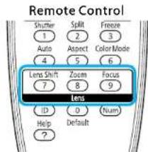
Procedure

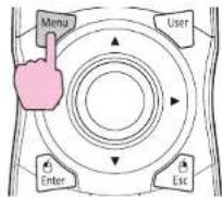
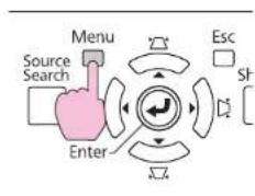
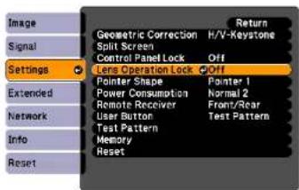
Press the [Menu] button, and select Settings - "Lens Operation Lock" from the configuration menu "Using the Configuration Menu" p.47
Using the Remote Control Using the Control Panel
flowchart
graph TD
    A["Menu"] --> B["Source Search"]
    B --> C["Enter"]
    C --> D["Esc"]
    D --> E["Shift"]

Select "On".
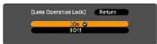
The buttons related to the lens operation are locked according to the setting you chose.
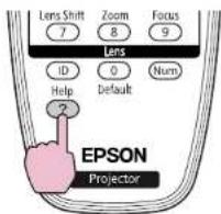
Remote control button lock
This function locks the following buttons on the remote control.
Remote Control
Procedure
Remote Control
Security Functions

Each time [Help] button is pressed for at least 5 seconds, the remote control button lock turns on or off.

Even if the remote control button lock is on, the following operations are possible.
- Resetting default for the Remote Receiver setting
- Entering numbers using the [Num] button and the numeric buttons
Anti-Theft Lock
As the projector is often setup on ceiling mounts and left in rooms unattended, the projector includes the following security devices to prevent someone from taking the projector.
- Security slot
The Security slot is compatible with the Microsaver Security System manufactured by Kensington. You can find details about the Microsaver Security System on the Kensington homepage http://www.kensington.com/.
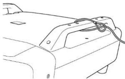
- Handle
A commercially available anti-theft wire lock can be passed through the security cable installation point to secure the projector to a desk or pillar.
Installing the wire lock
Pass an anti-theft wire lock through the handle.
See the documentation supplied with the wire lock for locking instructions.
natural_image
Line drawing of a car's front bumper with cable and mounting bracket (no text or symbols)Memory Function

Settings for the image in the configuration menu can be registered in memory, and can be used when needed. You can register up to ten types of memory.
Available Settings
Setting items in the configuration menu that can be registered in memory are listed below.
| Top Menu Sub Menu | |
| Image All setting items | |
| Signal Progressive | Frame Interpolation ^1 Super-resolutionNoise ReductionMosquito NRHDMI Video RangeSDI Video RangelScaleOverscan |
| Settings Power Consumption | *2 |
| Extended Brightness Level | *2Edge BlendingMulti-screen |
*1 EB-Z8455WU/Z8450WU only
*2 EB-Z8455WU/Z8450WU/Z8355W/Z8350W/Z10005/Z10000 only
Saving/Loading/Erasing the Memory
Saving the memory
Use the following procedure to register the memory.
Procedure

During projection, press the [Menu] button on the remote control or control panel, and select Settings - "Memory" from the configuration menu. "Using the Configuration Menu" p.47
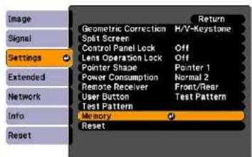

Select "Save Memory", and then press the Enter button.
![[Memory] Return Load Memory Save Memory Erase Memory Rename Memory Settings Extended Network Info Reset](/content/2026/05/815375/images/3f4dcb8d957c4fc765ca743abc200f5a816dc84318ae9d134b63ca9b7f4ac730.jpg)

Select the memory name that you want to register the setting, and then press the Enter button.
Current settings are registered in the memory.

If the mark on the left of the memory name is turned green, it means the memory has already been registered. When you select the registered memory, a message will ask if you want to overwrite memory. If you select Yes, the previous settings are deleted and the current settings are registered.
the
Loading the memory
Procedure

During projection, press the [Menu] button on the remote control or control panel, and select Settings - "Memory" from the configuration menu.

Select "Load Memory", and then press the Enter button.

Select the desired memory, and then press the Enter button. The settings registered to the memory are applied.
Erasing the memory
Procedure

Press the [Menu] button on the remote control or control panel, and select Settings - "Memory" from the configuration menu.

Select "Erase Memory", and then press the Enter button.

Select the desired memory, and then press the Enter button.

Select "Yes" when the confirmation message is displayed. The registered memory will be erased.
Renaming the memory
Procedure

Press the [Menu] button on the remote control or control panel, and select Settings - "Memory" from the configuration menu.

Select "Rename Memory", and then press the Enter button.

Select the desired memory, and then press the Enter button.

Enter the memory name using the soft keyboard. "Soft Keyboard Operations" p.61
Press [Finish] to complete renaming.

Configuration Menu
This chapter explains how to use the configuration menu and its functions.
The screen shots may be different from those shown in this chapter depending on your projector model.
Using the Configuration Menu

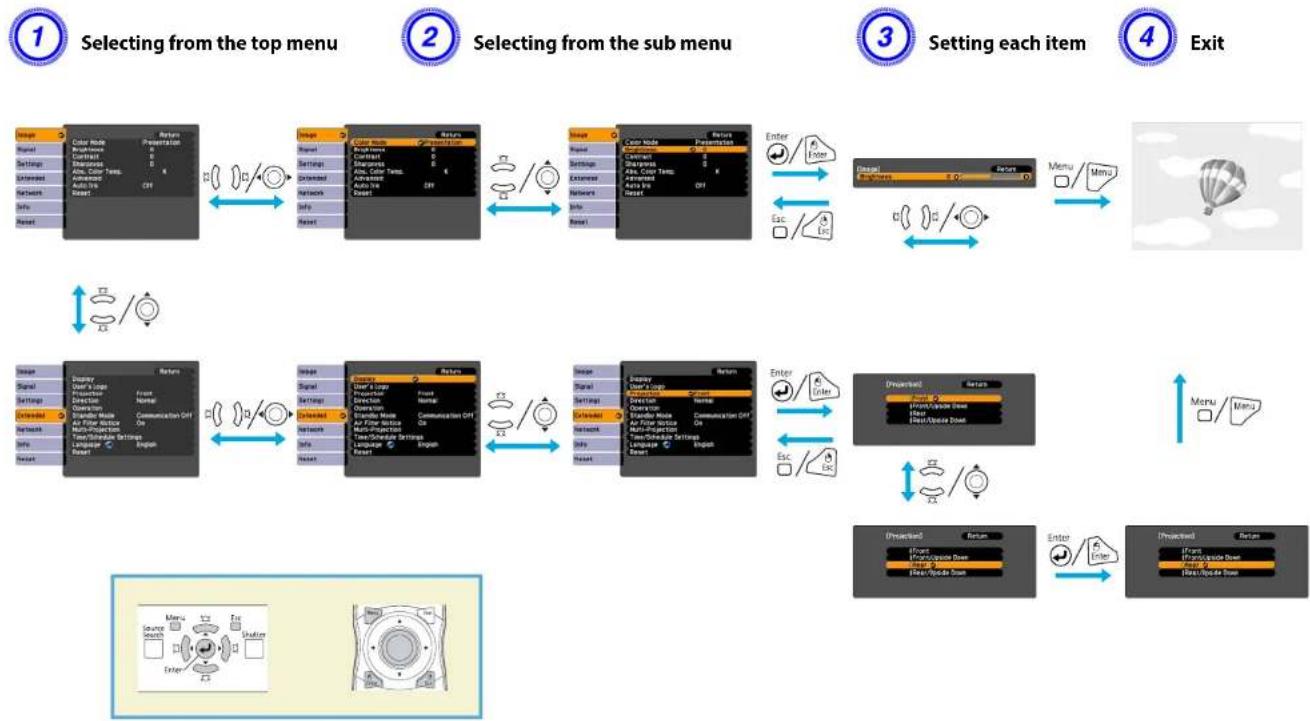
flowchart
graph TD
    A["1 Selecting from the top menu"] --> B["2 Selecting from the sub menu"]
    B --> C["3 Setting each item"]
    C --> D["4 Exit"]

    subgraph Section 1
        A1["Image Color Mode Presentation"]
        A2["Image Color Mode Background"]
        A3["Settings Controls"]
        A4["Settings Controls"]
        A5["Auto Wire Temp."]
        A6["Unknown"]
        A7["Network Auto Wire"]
        A8["Info"]
        A9["Reset"]
    end

    subgraph Section 2
        B1["Image Color Mode Presentation"]
        B2["Image Color Mode Background"]
        B3["Settings Controls"]
        B4["Settings Controls"]
        B5["Auto Wire Temp."]
        B6["Unknown"]
        B7["Network Auto Wire"]
        B8["Info"]
        B9["Reset"]
    end

    subgraph Section 3
        C1["Enter/Enter"]
        C2["Enter/Enter"]
        C3["Menu/Menu"]
        C4["Esc/Esc"]
    end

    subgraph Section 4
        D1["Display Profiles"]
        D2["Enter"]
        D3["Menu/Menu"]
        D4["Exit"]
    end

    subgraph Section 5
        E1["User Address"]
        E2["User Address Icon"]
        E3["User Address Icon"]
        E4["User Address Icon"]
        E5["User Address Icon"]
        E6["User Address Icon"]
        E7["User Address Icon"]
        E8["User Address Icon"]
        E9["User Address Icon"]
        E10["User Address Icon"]
        E11["User Address Icon"]
        E12["User Address Icon"]
        E13["User Address Icon"]
        E14["User Address Icon"]
        E15["User Address Icon"]
        E16["User Address Icon"]
        E17["User Address Icon"]
        E18["User Address Icon"]
        E19["User Address Icon"]
        E20["User Address Icon"]
        E21["User Address Icon"]
        E22["User Address Icon"]
        E23["User Address Icon"]
        E24["User Address Icon"]
        E25["User Address Icon"]
        E26["User Address Icon"]
        E27["User Address Icon"]
        E28["User Address Icon"]
        E29["User Address Icon"]
        E30["User Address Icon"]
        E31["User Address Icon"]
        E32["User Address Icon"]
        E33["User Address Icon"]
        E34["User Address Icon"]
        E35["User Address Icon"]
        E36["User Address Icon"]
        E37["User Address Icon"]
        E38["User Address Icon"]
        E39["User Address Icon"]
        E40["User Address Icon"]
    end

    subgraph Section 6
        F1["Display Profiles"]
        F2["Display Colors"]
        F3["Settings Controls"]
        F4["Settings Controls"]
        F5["Auto Wire Temp."]
        F6["Unknown"]
        F7["Network Auto Wire"]
        F8["Info"]
        F9["Reset"]
    end

    subgraph Section 7
        G1["User Address"]
        G2["User Address Icon"]
        G3["User Address Icon"]
        G4["User Address Icon"]
        G5["User Address Icon"]
        G6["User Address Icon"]
        G7["User Address Icon"]
        G8["User Address Icon"]
        G9["User Address Icon"]
        G10["User Address Icon"]
        G11["User Address Icon"]
        G12["User Address Icon"]
        G13["User Address Icon"]
        G14["User Address Icon"]
        G15["User Address Icon"]
        G16["User Address Icon"]
        G17["User Address Icon"]
        G18["User Address Icon"]
        G19["User Address Icon"]
        G20["User Address Icon"]
    end

    subgraph Section 8
        H1["User Address"]
        H2["User Address Icon"]
        H3["User Address Icon"]
        H4["User Address Icon"]
        H5["User Address Icon"]
        H6["User Address Icon"]
        H7["User Address Icon"]
        H8["User Address Icon"]
        H9["User Address Icon"]
    end

    subgraph Section 9
        I1["User Address"]
        I2["User Address Icon"]
        I3["User Address Icon"]
        I4["User Address Icon"]
        I5["User Address Icon"]
        I6["User Address Icon"]
        I7["User Address Icon"]
    end

    subgraph Section 10
        J1["User Address"]
        J2["User Address Icon"]
        J3["User Address Icon"]
        J4["User Address Icon"]
        J5["User Address Icon"]
    end

    subgraph Section 11
        K1["User Address"]
        K2["User Address Icon"]
    end

    subgraph Section 12
        L1["User Address"]
    end

    subgraph Section 13
        M1["User Address"]
    end

    subgraph Section 14
        N1["User Address"]
    end

    subgraph Section 15
        O1["User Address"]
    end

    subgraph Section 16
        P1["User Address"]
    end

    subgraph Section 17
        Q1["User Address"]
    end

    subgraph Section 18
        R1["User Address"]
    end

    subgraph Section 19
        S1["User Address"]
    end

    subgraph Section 20
        T1["User Address"]
    end

    subgraph Section 21
        U1["User Address"]
    end

    subgraph Section 22
        V1["User Address"]
    end

    subgraph Section 23
        W1["User Address"]
    end

    subgraph Section 24
        X1["User Address"]
    end

    subgraph Section 25
        Y1["User Address"]
    end

    subgraph Section 26
        Z1["User Address"]
    end

    subgraph Section 27
        AA1["User Address"]
    end

    subgraph Section 28
        AB1["User Address"]
    end

    subgraph Section 29
        AC1["User Address"]
    end

    subgraph Section 30
        AD1["User Address"]
    end

    subgraph Section 31
        AE1["User Address"]
    end

    subgraph Section 32
        AF1["User Address"]
    end

    subgraph Section 33
        AG1["User Address"]
    end

    subgraph Section 34
        AH1["User Address"]
    end

    subgraph Section 35
        AI1["User Address"]
    end

    subgraph Section 36
        AJ1["User Address"]
    end

    subgraph Section 37
        AK1["User Address"]
    end

    subgraph Section 38
        AL1["User Address"]
    end

    subgraph Section 39
        AM1["User Address"]
    end

    subgraph Section 40
        AN1["User Address"]
    end

    subgraph Section 41
        AO1["User Address"]
    end

    subgraph Section 42
        AP1["User Address"]
    end

    subgraph Section 43
        AQ1["User Address"]
    end

    subgraph Section 44
        AR1["User Address"]
    end
Configuration Menu
Items that can be set vary depending on the image signal or input source currently being projected, or the model you are using.
| Top Menu Sub | Menu Items/Values | |
| Image Menu p.51 | Color Mode | Dynamic, Presentation, Theatre, Photo, Sports, sRGB, DICOM SIM, Multi-Projection |
| Brightness -24 to 24 | ||
| Contrast -24 to 24 | ||
| Color Saturation -32 to | 32 | |
| Tint -32 to 32 | ||
| Sharpness -5 to 5 | ||
| Abs. Color Temp. | 5000K to 10000K | |
| Advanced Gamma, RGB, | RGBCMY | |
| Auto Iris | On, Off | |
| Signal Menu p.53 | Auto Setup | On, Off |
| Resolution | Auto, Wide, Normal, Manual | |
| Tracking | - | |
| Sync. | - | |
| Position | - | |
| Progressive | Off, Video, Film/Auto | |
| Frame Interpolation1 | Off, Low, Normal, High | |
| Super-resolution | 0 to 3 | |
| Noise Reduction Off, NR1, NR2 | ||
| Mosquito NR | On, Off | |
| Top Menu Sub | Menu Items/Values | |
| HDMI Video Range | Auto, Normal, Expanded | |
| SDI Video Rang& | Normal, Expanded | |
| Input Signal | Auto, RGB, Component | |
| Video Signal Auto, NTSC | C, NTSC4.43,PAL, M-PAL, N-PAL,PAL60, SECAM | |
| Aspect | Normal, Auto, 4:3, 16:9,16:9 (Up), 16:9 (Down),Full, Zoom, Native | |
| Scale | - | |
| Overscan | Auto, Off, 4%, 8% | |
| Settings Menup.55 | Geometric Correction | H/V-Keystone, QuickCorner, Arc Correction,Point Correction |
| Split Screen | - | |
| Control Panel Lock | Full Lock, Partial Lock,Off | |
| Lens Operation Lock | On, Off | |
| Pointer Shape | Pointer 1, 2, 3 | |
| Power Consumption*2 | Normal 1, ECO, Normal2 | |
| Remote Receiver Front/Rear | Rear, Front, Rear,Off | |
| User Button Power Consumption *2,Info, Progressive, TestPattern, Multi-screen,Resolution, Memory | ||
| Test Pattern | - | |
| Memory | Load Memory, SaveMemory, Erase Memory,Rename Memory | |
| Extended Menu p.57 | Display Menu Position, | Messages, Display Background, Startup Screen |
| User's Logo - | ||
| Projection Front, Front/Upside Down, Rear, Rear/Upside Down | ||
| Direction Normal, Pointing Up, Pointing Down, Angled Up, Angled Down | ||
| Operation Direct Power | On, Sleep Mode, Sleep Mode Timer, Shutter Button, Shutter Timer, High Altitude Mode, BNC Sync Termination, Remote Control Type, Beep | |
| Standby Mode Communication On, Communication Off | ||
| Air Filter Notice On, Off | ||
| Multi-Projection Brightness Level *2, Edge Blending, Multi-screen, Projector ID | ||
| Time/Schedule Settings - | ||
| Language 27 languages | ||
| Info Menu p.77 | Lamp Hours | - |
| Lamp Status | - | |
| Source | - | |
| Input Signal | - | |
| Resolution | - | |
| Top Menu Sub | Menu Items/Values | |
| Video Signal - | ||
| Refresh Rate | - | |
| Sync Info | - | |
| Status | - | |
| Serial Number - | ||
| Event ID | - | |
| Reset Menu p.79 | Reset All | - |
| Reset Memory - |
*1 EB-Z8455WU/Z8450WU only
*2 EB-Z8455WU/Z8450WU/Z8355W/Z8350W/Z10005/Z10000 only
Network Menu
| Top Menu Sub | Menu Items/Values | |
| Basic Menu p.62 | Projector Name | - |
| Web Remote Password | - | |
| Projector Keyword | On, Off | |
| Wireless LAN Menu p.63 | Wireless LAN Power | On, Off |
| Wi-Fi Protected Setup | - | |
| Wireless LAN system | 802.11b/g/n, 802.11b/g | |
| Connection Mode | Quick, Advanced | |
| SSID Auto Setting | On, Off | |
| SSID | - | |
| Search Access Point | - | |
| Channel | 1ch, 6ch, 11ch | |
| SSID Display | On, Off | |
| DIICP | On, Off | |
| IP Address - | ||
| Subnet Mask - | ||
| Gateway Address - | ||
| IP Address Display On, Region Code - | Off | |
| Security Menu p.66 | Security Open, WPA/WPA2-PSK, WPA/WPA2-EAP | |
| Wired LAN Menu p.70 | DHCP On, Off | |
| IP Address - | ||
| Subnet Mask - | ||
| Gateway Address - | ||
| IP Address Display On, | Off | |
| Administrator Settings Menu p.71 | Administrator Password - | |
| Network Host Name - | ||
| PJLink Password | - | |
| Web Control Password | - | |
| Monitor Password | - | |
| Secure HTTP | On, Off | |
| Mail Notification - | ||
| Manage Certificates | - | |
| SNMP | - | |
| Priority gateway | Wired, Wireless | |
| AMX Device Discovery | On, Off | |
| Crestron RoomView | On, Off | |
| Bonjour | On, Off | |
| EPSON Message Broadcasting | On, Off | |
Image Menu

Items that can be set vary depending on the image signal or input source currently being projected as shown in the following screen shots. Setting details are saved for each image signal.
RGB Signal/LAN
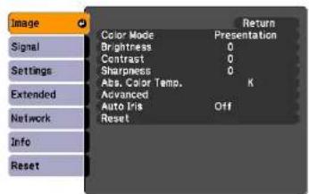
Component Video Signal
Composite video Signal ▶ /S-Video Signal ▶
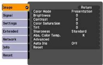
| Sub Menu Function | |
| Color Mode | You can select the quality of the image to suit your surroundings. p.28 |
| Brightness | You can adjust the image Brightness. |
| Contrast | You can adjust the difference between light and shade in the images. |
| Color Saturation | You can adjust the Color Saturation for the images. |
| Tint | You can adjust the image Tint. |
| Sharpness | Standard: You can adjust the image sharpness. To make more-detailed settings, select Advanced. Advanced: The following four items can be set. Thin Line Enhancement: If this parameter is set to a positive value, details such as hair or fabric patterns will be enhanced. Thick Line Enhancement: If this parameter is set to a positive value, the outline, background, and the other main parts of the objects in the image will be enhanced to show them clearly. Vert. Line Enhancement: If this parameter is set to a positive value, vertical lines in the image are enhanced. Horiz. Line Enhancement: If this parameter is set to a positive value, horizontal lines in the image are enhanced. |
| Abs. Color Temp. | You can adjust the overall tint of the image. You can adjust tints in 10 stages from 5000 K to 10000 K. When a high value is selected, the image becomes tinged with blue, when a low value is selected, the image becomes tinged with red. |
| Advanced | You can make adjustments by choosing the following items.Gamma: You can adjust the coloring by selecting one of the gamma correction values, or referring to the projected image or a gamma graph.RGB: You can adjust the individual R (red), G (green), and B (blue) components of the offset and gain.RGBCMY: You can adjust the hue, saturation, and brightness of each color R (red), G (green), B (blue), C (cyan), M (magenta), Y (yellow) individually. |
| Auto Iris* | (This item can be selected when Dynamic or Theatre is selected as the Color Mode setting from the Image menu.)Set whether or not (On/Off) to adjust to the optimum light status for images being projected.The setting is stored for each Color Mode. |
| Reset | You can reset all adjustment values for the Image menu functions to their default settings. To return all menu items to their default settings, see p.79 |
* This item cannot be set if Edge Blending is set to On.
Signal Menu

Items that can be set vary depending on the image signal or input source currently being projected as shown in the following screen shots. Setting details are saved for each image signal.
You cannot make settings in the Signal menu other than Scale when the input source is LAN.
RGB Signal
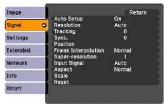
Component Video Signal
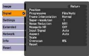
Composite video Signal ▶/S-Video Signal ▶
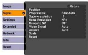
HDMI/SDI*
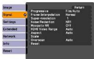
* EB-Z8455WU/Z8450WU only
| Sub Menu Function | |
| Auto Setup | You can select whether or not (On/Off) Auto Setup automatically adjusts the image to the optimum state when the input signal changes. |
| Resolution | Auto: The resolution of the input signal is automatically identified.Wide, Normal: If the images cannot be projected correctly when Auto is set, set this menu. Set to Wide depending on the connected computer for wide screens, or set to Normal for 4:3 or 5:4 screens.Manual: You can specify the resolution. This is ideal when connected computer is fixed. |
| Tracking | You can adjust computer images when vertical stripes appear in the images. |
| Sync. | You can adjust computer images when flickering, fuzziness, or interference appear in the images. |
| Position | You can adjust the display Position up, down, left, and right when a part of the image is missing so that the whole image is projected. |
| Progressive | Off: IP conversion is carried out for each field in the screen. This is ideal for viewing images with a large amount of movement.Video: This is ideal for viewing general video images.Film/Auto: By automatically converting movie films, CG, animated images, and so on recorded in 24/30 frames to the optimum progressive signal via 2-3 pull-down, it is possible to recreate the natural feel of the original image. |
| Frame Interpolation* | You can play fast moving images smoothly by producing intermediate frames between the original frames. |
| Super-resolution | To display a crisp image, you can reduce the blurring that is created on the edge when the image data is scaled up to fit the panel resolution of the image signal. |
| Noise Reduction | Smoothes out rough images. There are two modes. Select your favorite setting. It is recommended that this is set to Off when viewing image sources in which noise is very low, such as for DVDs. |
| Mosquito NR | You can reduce the wavy noise that occurs in lines between areas with dramatic changes in colors. |
| HDMI Video Range | When the HDMI1/2 input port is connected to a DVD player, set the video level according to the video level setting of the DVD player. If Auto is selected, the video level of the input signal is identified and set automatically. If the range is set to Auto and the image shows whiteout or blackout, set the video level according to the video level setting of the DVD player. The video level of the DVD player may be set to Normal or Expanded. |
| SDI Video Range | When the SDI input port is connected to a video equipment, set the video level according to the video level setting of the video equipment. |
| Input Signal | You can select an input signal from Computer input port or BNC input port.If Auto is set, the input signal is identified automatically according to the connected equipment.If colors do not appear correctly when this is set to Auto, select the appropriate signal according to the connected equipment. |
| Video Signal | You can select an input signal from Video input port or S-Video input port. If set to Auto, video signals are recognized automatically. If interference appears in the image or a problem occurs such as no image is being projected when set to Auto, select the appropriate signal according to the connected equipment. |
| Aspect | You can set thAspect Ratio ^ for projected images. ^ p.22 |
| Scale | When you set Edge Blending from Extended menu, you can adjust an overlapping area, scaling up each image and selecting the range to display.Full Display: You can adjust while renewing the display area aspect and position.Zoom Display: You can adjust while locking the display area aspect and position. |
| Overscan | You can change the Output Scaling (the range of projected image). The range of trimming screen can be set to Off, 4%, or 8%. You can select Auto only when the input source is HDMI1/2. When Auto is selected, the range is automatically switched to Off or 8% according to the input signal. |
| Reset | You can reset all adjustment values on the Signal menu to their default settings, except for Input Signal.To return all menu items to their default settings, see ^ p.79 |
* EB-Z8455WU/Z8450WU only
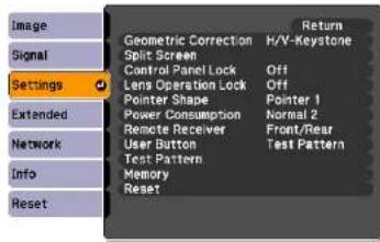
| Sub Menu Function | |
| Geometric Correction | You can correct distortion.H/V-Keystone: Corrects horizontal and vertical keystone distortion. Select one of V-Keystone or H-Keystone. p.142Use the [□▲], [□/▼], [◇/◇], and [◇/◇] buttons on the control panel to perform similar corrections to V-Keystone and H-Keystone.Quick Corner: Selects and corrects the four corners of the projected image. p.140Arc Correction: Fine adjustment of the curved distortion caused by slack or shrinkage of the screen. p.143Point Correction: The projected image is divided by the grid, and you can correct the distortion by moving the point of intersection from side to side and up and down. p.153 |
| Split Screen | You can split the screen into two screens. p.29 |
| Control Panel Lock | You can use this to restrict operation of the projector's control panel. p.40 |
| Lens Operation Lock | You can use this to restrict the lens operation of the remote control. p.41 |
| Pointer Shape | You can select the shape of the pointer. p.34Pointer 1: Pointer 2: Pointer 3: ▲ |
| Power Consumption* | You can set the lamp brightness to Normal 1, ECO, or Normal 2.Normal 1: Projects at normal brightness.You can change the lamp brightness in Multi-Projection - Brightness Level from the Extended menu. p.57ECO: Select this if the images being projected are too bright such as when projecting images in a dark room or onto a small screen. When ECO is selected, the amount of electricity consumed and the fan rotation noise during projection are reduced, and the lamp's operating life is extended.Normal 2: Adjusts the brightness automatically according to the surrounding environment. |
| Remote Receiver | You can limit the reception of the operation signal from the remote control.When you want to prohibit operation by remote control, or if the remote receiver has a fluorescent light too close to it, you can make settings to deactivate the remote receiver you do not want to use or that is experiencing interference.If the [Menu] button on the remote control is pressed for 15 seconds, this parameter will return to the default setting. |
| User Button | You can select the item assigned from the configuration menu with the remote control's [User] button. By pressing the [User] button the assigned menu item selection/adjustment screen is displayed, allowing you to make one-touch settings/adjustments. You can assign one of the following items to the [User] button.Power Consumption*, Info, Progressive, Test Pattern, Multi-screen, Resolution, Memory |
| Test Pattern | When the projector is setup, a Test Pattern is displayed so that you can adjust the projection without connecting other equipment.p.137 |
| Memory | Load Memory: Recalls the setting value registered in Save Memory.p.45You cannot select if nothing is registered by Save Memory.Save Memory: Registers settings related to the image in the configuration menu as memory.p.44Erase Memory: Deletes unnecessary memoriesp.45Rename Memory: Changes the name of the registered memory.p.45 |
| Reset | You can reset all adjustment values on the Settings menu to their default settings, except for User Button and Memory.To return all menu items to their default settings, see p.79 |
* EB-Z8455WU/Z8450WU/Z8355W/Z8350W/Z10005/Z10000 only
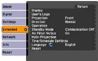
| Sub Menu Function | |
| Display | You can make settings related to the projector's display.Menu Position: Select the position to display the menu on the projected screen.Messages: The following messages are not displayed on the screen when this item is set to Off.Overheating and other warnings, messages such as when there is no video input, and when Freeze is On or when changing Source, Color Mode or Aspect.Display Background ^1 : You can set the screen status for when there is no video input to Black, Blue, or Logo.Startup Screen ^1 : Set this parameter to On to display the user's logo when projection is started. |
| User's Logd ^1 | You can change the User's Logo that is displayed as a background during Display Background or Startup Screen. p.36 |
| Projection | Set this parameter according to the installation status of the projector. p.130 |
| Direction | Set this parameter according to the installation status of the projector. p.130 |
| Operation | Direct Power On: You can set whether or not (On/Off) to enable Direct Power On.Be careful when this item is set to On because this unit turns on at the time of power recovery with this unit plugged-in to an outlet.Sleep Mode: When set to On, this automatically stops projection when no image signal is being input and no operations are carried out.Sleep Mode Timer: When Sleep Mode is set to On, you can set the time before the projector automatically turns off within a range of 1 to 30 minutes.Shutter Button: Select an operation to be done when the [Shutter] button is pressed. When Electric Shutter is selected, the electric shutter opens/closes. p.33 When Blank is selected, this turns off the video temporarily.Shutter Timer: When set to On, this turns off the power automatically 30 minutes after the electric shutter is closed.Shutter Timer is set to On at the time of purchase. (When Shutter Timer and Sleep Mode are set to On at the same time, Sleep Mode has priority.)High Altitude Mode: Set to On when using the projector above an altitude of 1500 m.BNC Sync Termination: Set the termination for the signal from the BNC input port. This should usually be set to Off. Set to On when analog (75Ω) termination such as for switchers is necessary.Remote Control Type: You can select Normal or Simple depending on the type of remote control.Set this item to Normal to use the remote control provided with the projector. When Simple is selected, you can use the remote control provided with other Epson projectors to operate this projector. This is useful if you want to use a remote control that you are already familiar with to operate the projector. (When using the remote control that is supplied with an EB-G5xxx-series or EB-Z80xx-series projector, select Normal.)However, you cannot use the remote control provided with this projector if this is set to Simple. Make sure that the setting is correct because, if the projector is mounted on the ceiling or somewhere hard to reach, changing it back to Normal may be difficult. Additionally, you cannot use the functions that are not equipped with this projector or the remote control which you use.Beep: When this is set to On, the confirmation buzzer beeps to notify you that the power turns on or off, the electric shutter opens or closes, or the cooling down is finished. |
| Standby Mode | You can use the functions that monitor and control the status of the projector over the network even when the projector is in standby mode if this is set tCommunication On. |
| Air Filter Notice | You can set whether or not (On/Off) to enable Air Filter Notice. When this is set to On and a clog in the air filter is detected, the message is displayed on the screen. |
| Multi-Projection | You can make settings for the useful functions to project images using multiple projectors. p.150Brightness Level (EB-Z8455WU/Z8450WU/Z8355W/Z8350W/Z10005/Z10000 only): Set the lamp brightness level between 1 and 5. This item can be adjusted when Normal 1 is selected in the Power Consumption setting from the Settings menu.Edge Blending: Corrects a border between multiple images to create a seamless screen. p.155Multi-screen: You can adjust the hue and brightness of each projected image. p.157Projector ID: Set the ID within a range of 1 to 9. Off indicates that no ID is set. p.150 |
| Time/Schedule Settings | Displays the screen to set the current time and schedules. p.159 |
| Language | You can set the Language for message displays. |
| Reset | You can reset Display^2 , Operation^*3 , Air Filter Notice, and Multi-Projection^*4 from the Extended menu to their default settings. To return all menu items to their default settings, see p.79 |
*1 When User's Logo Protect is set to On in Password Protect, settings relating to User's Logo cannot be changed. You can make changes after setting User's Logo Protect to Off. p.38
*2 Except for parameters related to the user's logo
*3 Except for High Altitude Mode and Remote Control Type
*4 Except for Multi-screen and Projector ID
Network Menu

When Network Protect is set to On in Password Protect, a message is displayed and the settings cannot be changed. You can make changes after setting Network Protect to Off p.38
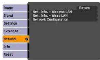
| Sub Menu Function | |
| Net. Info. - Wireless LAN Net. Info. - Wired LAN | Displays the network settings. |
| Network Configuration | Displays the screen to set the network. p.61 |

By using the Web browser of a computer connected to the projector on a network, you can set the projector's functions and control the projector. This function is called "Web Control". You can easily enter text using a keyboard to make settings for "Web Control" such as security settings. p.109
Notes on Operating the Network Menu
Selecting from the top menu and sub menus, and changing of selected items are the same as operations in the configuration menu.
When done, make sure you go to the Setup complete, and select one of Yes, No, or Cancel. When you select Yes or No, you return to the configuration menu.
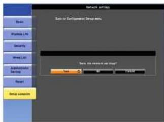
Yes: Saves the settings and exits the Network menu.
No: Exits to the Network menu without saving the settings.
Cancel: Continues displaying the Network menu.

If the settings contain an invalid value, the settings may not take effect, even after you select Yes.
Soft Keyboard Operations
The Network menu contains items that require input of alphanumeric during setup. In this case, the following software keyboard is displayed. Use the || button on the remote control or [/], [/], [/] , and [/] on the projector to move the cursor to the desired key, and then press the Enter button to enter the alphanumeric. Enter figures by holding
down the [Num] button on the remote control, and pressing the numeric buttons. After inputting, press [Finish] on the keyboard to confirm your input. Press [Cancel] on the keyboard to cancel your input.
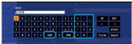
• Each time the [CAPS] key is selected and the Enter button is pressed, it switches between uppercase and lowercase letters.
• Each time the [SYM1/2] key is selected and the Enter button is pressed, it switches the symbol keys in the section enclosed in the box.
Basic Menu
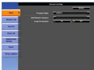
| Sub Menu Function | |
| Projector Name | Displays the projector name used to identify the projector when connected to a network.When editing, you can enter up to 16 single-byte alphanumeric characters. |
| Web Remote Password | Set a password to use Web Remote. You can enter up to 8 single-byte alphanumeric characters. Web Remote is a computer function that allows you to operate the projector by using the Web browser on a computer connected on a network. p.109 |
| Projector Keyword | When set to On, you have to enter the keyword when you try to connect the projector to a computer using EasyMP Multi PC Projection and EasyMP Network Projection. As a result, you can prevent presentations from being interrupted by unscheduled connections from the computer.Normally this should be set to On. |
Wireless LAN Menu
To connect the projector to a computer using a wireless LAN, install the Wireless LAN unit (ELPAP07). p.165
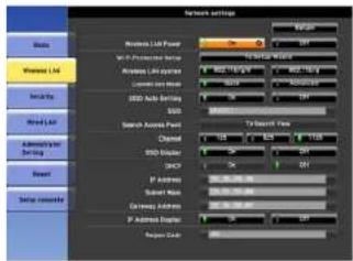
| Sub Menu Function | |
| Wireless LAN Power | Set this parameter to On when connecting the projector and a computer via a wireless LAN. If you do not want to connect via a wireless LAN, set this parameter to Off to prevent unauthorized access by others. |
| Wi-Fi Protected Setup | When using a WPS (Wi-Fi Protected Setup) compatible access point via a wireless LAN, you can easily connect the projector to the access point and make security settings. p.125 |
| Wireless LAN system | Sets the wireless LAN system. Normally this should be set to 802.11b/g/n. The connection method is selected automatically according to the access point settings.In an area that does not support 802.11n, only 802.11b/g is displayed. |
| Connection Mode | Set the connection mode to use when connecting the projector and a computer via a wireless LAN.If you select Quick, a small network is created automatically by the projector and computer. It is used with EasyMP Network Projection. If SSID Auto Setting is On, the projector becomes an easy access point; if it is set to Off, the network is created in Ad hoc mode. If you select Advanced, the connection is established by the installed access point and Infrastructure mode. |
| SSID Auto Setting | If Connection Mode is set to Quick, when you set this to On, you can search for the projector more quickly from among multiple projectors. SSID is set automatically.When connecting to multiple projectors from 1 computer in Quick mode, set this to Off, and set the same SSID in all the projectors that will connect. |
| SSID | Enter an SSID. When an SSID is provided for the wireless LAN system in which the projector participates, enter the SSID.You can enter up to 32 single-byte alphanumeric characters. Set SSID to blank or ANY to establish an ANY connection. |
| Search Access Point | When Connection Mode is set to Advanced, you can search for surrounding access points, and set the SSID to be connected from those access points. Depending on the access point settings, they may not be displayed in the list. You must set security separately. p.65 |
| Channel | You can select the channels used to connect in Quick mode. If interference from other signals occurs, use a different channel. |
| SSID Display | To prevent the SSID from being displayed on the LAN Standby screen, set this to Off. |
| DHCP | You can set whether or not (On/Off) to use DHCP .If this is set to On you cannot set any more addresses. |
| IP Address | You can input the IP address assigned to the projector.You can input a number from 0 to 255 in each field of the address. However, the following IP addresses cannot be used. 0.0.0.0, 127.x.x.x, 224.0.0.0 to 255.255.255.255 (where x is a number from 0 to 255) |
| Subnet Mask | You can input the Subnet Mask for the projector. You can input a number from 0 to 255 in each field of the address. However, the following subnet masks cannot be used.0.0.0.0, 255.255.255.255 |
| Gateway Address | You can input the IP address for the gateway for the projector.You can input a number from 0 to 255 in each field of the address. However, the following Gateway addresses cannot be used.0.0.0.0, 127.x.x.x, 224.0.0.0 to 255.255.255.255 (where x is a number from 0 to 255) |
| IP Address Display | To prevent the IP address from being displayed on the LAN Standby screen, set this to Off. |
| Region Code | This is a specific string of the wireless LAN module. |
Network Menu

Search Access Point screen
Detected access points are displayed in a list.
Access points set by WEP are also detected, but connection is not possible because this projector does not support the WEP encryption method.
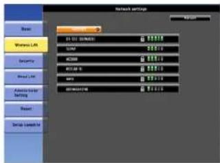
| Sub Menu/Icon Function | |
| Refresh | Starts detecting access points again. |
 | Indicates an already set access point. |
 | Indicates the access points where security is set.If you select an access point not set to security, Wireless LAN menu appears.If you select an access point which has security, Security menu appears. Set security according to the access point settings. |
Security Menu (Only Available when the Optional Wireless LAN Unit Is Installed)
When the Wireless LAN unit is installed, it is strongly recommended that you set security.
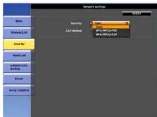
| Sub Menu Function | |
| Security | You can select a type of security.When Quick is selectedOpen: Security is not set.WPA/WPA2-PSK (only when SSID Auto Setting is On): Communication takes place using security by WPA2. Uses AES method for encryption.When establishing connection from computer to projector, enter the value set in the passphrase.When Advanced is selectedOpen: Connects to access points not set to security.WPA/WPA2-PSK: Connects in WPA personal mode. Encryption method is selected automatically according to the access point settings. Set a passphrase which is the same for the access point.WPA/WPA2-EAP: Connects in WPA enterprise mode. Encryption method is selected automatically according to the access point settings. Also select this item when using LEAP. |

You cannot set WEP as an encryption method for this projector.
When WPA/WPA2-PSK is selected
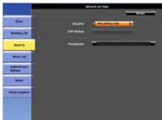
| Sub Menu Function | |
| Passphrase | You can enter at least 8 and up to 63 single-byte alphanumeric characters for the passphrase. When the passphrase is entered and the [Enter] button is pressed, the value is set and displayed as an asterisk (*).When using it with EasyMP Network Projection, you do not need to input the passphrase in the computer if it is the initial (default) passphrase.It is recommended to change the passphrase periodically for the purpose of security. If the network settings are initialized, it returns to the initial passphrase. p.76You cannot enter more than 32 characters on the configuration menu. When setting from Web Control, you can enter more than 32 characters.p.109In Quick mode, the initial passphrase is set. |
When WPA/WPA2-EAP is selected
PEAP/EAP-Fast PEAP-TLS/EAP-TLS LEAP
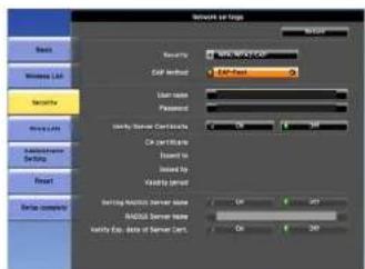
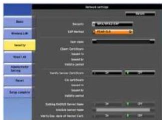
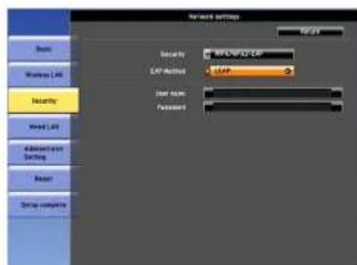
| Sub Menu Function | |
| EAP Method | Set the protocol for authentication.PEAP: Authentication protocol widely used in Windows Server.PEAP-TLS: Authentication protocol used in Windows Server. Set when using client certificate.EAP-TLS: Authentication protocol widely used to use a client certificate.EAP-Fast, LEAP: Select this when these authentication protocols are used. |
| User name | You can enter a user name to be used for authentication in single-byte alphanumeric characters (no spaces). You can enter up to 64 characters.If you select PEAP-TLS or EAP-TLS, the user name obtained automatically from the client certificate is displayed. You can change the user name, if the authentication server requires another user name.You cannot enter more than 32 characters on the configuration menu. When setting from Web Control, you can enter more than 32 characters.p.109If you must also enter the domain name, add the domain name before user name separated by a backslash. |
| Password | You can enter an authentication password in single-byte alphanumeric characters. You can enter up to 64 characters. When the password is entered and the [Enter] button is pressed, the value is set and displayed as an asterisk (*).You cannot enter more than 32 characters on the configuration menu. When setting from Web Control, you can enter more than 32 characters.p.109 |
| Client Certificate | Issued to/Issued by/Validity periodDisplays the information set in the stored client certificate. It is blank if the certificate is not set. |
| Verify Server Certificate | Set whether or not to do verify with the authentication server certificate to prevent illegal authentication. To select On, you must set a CA certificate that can verify the authentication server certificate. p.111 |
| CA certificate | Issued to/Issued by/Validity periodDisplays the information set in the stored CA certificate. It is blank if the certificate is not set. |
| Setting RADIUS Server Name | Set whether or not to do verify the authentication server name during the server certificate verification. If you set this to On and specify the server name, you reduce the risk of connecting to an invalid authentication server. |
| RADIUS Server Name | Specify the authentication server name.You can enter up to 32 single-byte alphanumeric characters. |
| Verify Exp. date of Server Cert. | Set whether or not to verify the expiration date of the certificate during the server certificate verification. If On is selected, the validity of the authentication server certificate is verified from the internal time of the projector. |
Wired LAN Menu
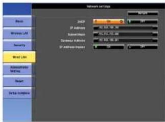
| Sub Menu Function | |
| DHCP | You can set whether or not (On/Off) to use DHCPIf this is set to On you cannot set any more addresses. |
| IP Address | You can input the IP address assigned to the projector.You can input a number from 0 to 255 in each field of the address. However, the following IP addresses cannot be used.0.0.0.0, 127.x.x.x, 224.0.0.0 to 255.255.255.255 (where x is a number from 0 to 255) |
| Subnet Mask | You can input the Subnet Mask for the projector. You can input a number from 0 to 255 in each field of the address. However, the following subnet masks cannot be used.0.0.0.0, 255.255.255.255 |
| Gateway Address | You can input the IP address for the gateway for the projector.You can input a number from 0 to 255 in each field of the address. However, the following Gateway addresses cannot be used.0.0.0.0, 127.x.x.x, 224.0.0.0 to 255.255.255.255 (where x is a number from 0 to 255) |
| IP Address Display | To prevent the IP address from being displayed on the LAN Standby screen, set this to Off. |
Administrator Settings Menu
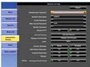
| Sub Menu Function | |
| Administrator Password | This is the password for the Administrator settings menu of network settings.You can enter up to 16 single-byte alphanumeric characters.If the administrator password is not set, click OK with an empty password box. |
| Network Host Name | You can enter up to 15 single-byte alphanumeric characters. |
| PJLink Password | Set a password to use when you access the projector using compatible PJLink software. p.117You can enter up to 32 single-byte alphanumeric characters. |
| Web Control Password | Set a password to use when making settings and controlling the projector using Web Control. You can enter up to 8 single-byte alphanumeric characters. Web Control is a computer function that allows you to set up and control the projector by using the Web browser on a computer connected on a network. p.109 |
| Monitor Password | You can enter up to 16 single-byte alphanumeric characters. |
| Secure HTTP | Apply security (HTTPS) to Web Control. To set security by Web control, it is recommended to set it On. |
| Mail Notification | Goes to the Mail Notification setting menu. p.73 |
| Manage Certificates | Goes to the Manage Certificates settings menu. p.74 |
| SNMP | Goes to the SNMP settings menu. p.75 |
| Priority Gateway | For the priority gateway, select either Wired or Wireless. |
| AMX Device Discovery | When the projector is connected to a network, set this to On to allow the projector to be detected by AMX Device Discovery. Set this to Off if you are not connected to an environment controlled with a controller from AMX or AMX Device Discovery. |
| Crestron RoomView | Set this parameter toOnonly when using Crestron RoomView® to monitor and control the projector over a network. Normally, leave this parameter set toOff. "About Crestron RoomView*" p.118Changes in projector settings take effect upon restarting.The following functions cannot be used when it is set toOn.Web ControlMessage Broadcasting (EasyMP Monitor plugin) |
| Bonjour | To connect to the network by Bonjour, set it toOn. For an explanation of the Bonjour service, see the Apple Web site.http://www.apple.com/ |
| EPSON Message Broadcasting | You can switch the EPSON Message Broadcasting function to enable or disable.You can download Mssceg Broadcasting and its Operation Guide from the following Web site.http://www.cpson.com |
Mail Notification menu
When this is set, you receive an e-mail notification if a problem or warning occurs in the projector. "Reading Problem Mail Notification Function" p.113
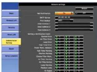
| Sub Menu Function | |
| Mail Notification | You can set whether or not (On/Off) to be notified by e-mail. |
| SMTP Server | You can input the IP address ➔ for the SMTP server for the projector.You can input a number from 0 to 255 in each field of the address. However, the following IP addresses cannot be used.127.x.x.x, 224.0.0.0 to 255.255.255.255 (where x is a number from 0 to 255) |
| Port Number | You can input the port number for the SMTP server. The default value is 25. You can input numbers between 1 to 65535. |
| Email Address 1/Email Address 2/Email Address 3 | You can input the e-mail address of the destination to send the notification e-mail to. You can register up to three destinations. You can enter up to 64 single-byte alphanumeric characters for the e-mail addresses. You cannot enter more than 32 characters on the configuration menu. When setting from Web Control, you can enter more than 32 characters. p.109 |
| Setting a Notification Event | You can select the problems or warnings to be notified about by e-mail. When the selected problem or warning occurs in the projector, an e-mail is sent to the specified Email Address notifying that a problem or warning has occurred. You can select multiple items from the displayed items. Sender is Email Address 1. |
Manage Certificates menu
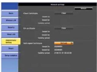
| Sub Menu Function | |
| Client Certificate | Issued to/Issued by/Validity periodDisplays the information set in the stored client certificate. It is blank if the certificate is not set. You must set the certificate if you use PEAP-TLS and EAP-TLS.Select Clear to delete the stored certificate. |
| CA certificate | Issued to/Issued by/Validity periodDisplays the information set in the stored CA certificate. It is blank if the certificate is not set. You must set the certificate if you use EAP to authenticate the authentication server certificate.Select Clear to delete the stored certificate. |
| Self-signed Certificate | Issued to/Issued by/Validity periodWhen Secure HTTP is set to On, information on the certificate maintained by the server function in the projector is displayed. It is not displayed if Web Server Certificate is set.Select Refresh to update the self-signed certificate. |
| Web Server Certificate | Issued to/Issued by/Validity periodDisplays information on the certificates set in the projector, which are needed when Secure HTTP is set to On. It is not displayed if Self-signed Certificate is set.Select Clear to delete the stored certificate. |

Web Control is used to set certificates. "Setting Certificates" p.111
Network Menu

SNMP menu
To use SNMP to monitor the projector, you need to install the SNMP manager program on your computer. SNMP should be managed by a network administrator.
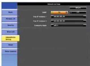
| Sub Menu Function | |
| SNMP | Set this parameter to On when using SNMP to monitor the projector. |
| Trap IP Address 1/Trap IP Address 2 | When SNMP is set to On, you can set up to two IP addresses as SNMP trap notification destinations.You can input a number from 0 to 255 in each field of the address.However, the following IP addresses cannot be used.127.x.x.x, 224.0.0.0 to 255.255.255.255 (where x is a number from 0 to 255) |
| Community Name | Set the community name of SNMP. You can enter up to 32 single-byte alphanumeric characters. |
Reset Menu
Resets all of the network settings.
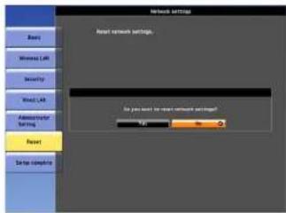
| Sub Menu Function | |
| Reset network settings. | To reset all of the network settings, select Yes.When you reset the network settings , the Passphrase, Administrator Password and Manage Certificates menu settings change back to their default values, and the certificates are deleted.After you reset all the settings, the Basic menu appears. |
Info Menu (Display Only)

Lets you check the status of the image signals being projected and the status of the projector. Items that can be displayed vary depending on the image signal or input source being projected as shown in the following screen shots.
RGB Signal/Component Video ▶ Signal Composite video ▶ Signal/S-Video ▶ Signal LAN
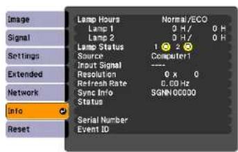
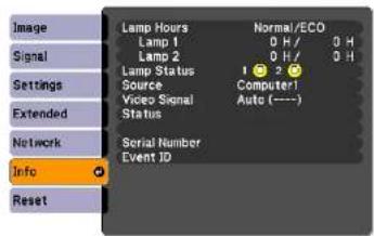
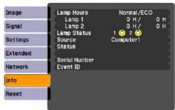
| Sub Menu Function | |
| Lamp Hours | You can display the cumulative lamp operating time.When it reaches the lamp warning time, the characters are displayed in yellow. |
| Lamp Status | The following icons show the status of the lamps.○: Lighted ☒: DisableWhen ☒ is displayed, the lamp is not operating normally. See "Reading the Indicators". ● p.83 |
| Source | You can display the Source name for the connected equipment currently being projected. |
| Input Signal | You can display the content of Input Signal set in the Signal menu according to the Source. |
| Resolution | You can display the Resolution. |
| Video Signal | You can display the content of Video Signal set in the Signal menu. |
| Refresh Rate | You can display theRefresh Rate. |
| Sync Info | You can display the image signal information.This information may be needed if service is required. |
| Status | This is information about errors that have occurred on the projector.This information may be needed if service is required. |
| Serial Number | Displays the projector's serial number. |
| Event ID | When problems occur when the projector and computer are connected through the network, information on the problem is displayed using an Event ID. Refer to the following page for information on interpreting the Event ID. p.96 |
*1 The cumulative use time is displayed as "011" for the first 10 hours. 10 hours and above is displayed as "1011", "1111", and so on.
*2 If you are using EB-Z8455WU/Z8450WU/Z8355W/Z8350W/Z10005/Z10000, it displays the lamp operating times of both power consumption mode and normal mode.
Reset Menu

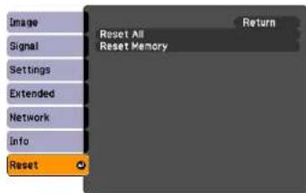
| Sub Menu Function | |
| Reset All | You can reset all items in the configuration menu to their default settings.The following items are not reset to their defaults: Items for Password, Input Signal, Memory, User's Logo, Multi-screen, all items for Network menus, Lamp Hours, and Language. |
| Reset Memory | Resets items for Memory in the Settings menu. |

Troubleshooting
This chapter explains how to identify problems and what to do if a problem is found.
Using the Help

If a problem occurs with the projector, the Help screen is displayed to assist you by pressing the [Help] button. You can solve problems by answering the questions.
Procedure

Press the [Help] button.
The Help screen is displayed.
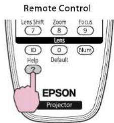
flowchart
graph TD
    A["Remote Control"] --> B["Lens Shift 7"]
    A --> C["Zoom 8"]
    A --> D["Focus 9"]
    A --> E["Lens ID"]
    A --> F["ID"]
    A --> G["0"]
    A --> H["Num"]
    A --> I["Help"]
    A --> J["Default"]
    A --> K["2"]
    A --> L["EPSON Projector"]

Select a menu item.
![[Help] The image is small. The image is distorted. The color tone is unusual. You cannot see the video.](/content/2026/05/815375/images/f0e0704c2d31b4405b155665b8a0236fc0ec8cd2a4db4d13acf93a7cf81613c1.jpg)
Remote Control
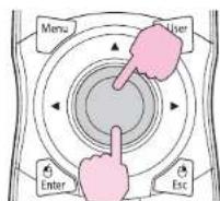

Confirm the selection.
Remote Control
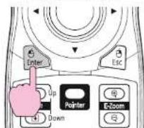
Questions and solutions are displayed as shown on the screen below. Press the [Help] button to exit Help.
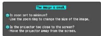
Using the Help


If the Help screen does not provide a solution to the problem, refer to "Problem Solving" p.83.
Problem Solving

If you are having a problem with the projector, first check the projector's indicators and refer to "Reading the Indicators" below.
If the indicators do not show clearly what the problem might be, refer to "When the Indicators Provide No Help". p.88
Reading the Indicators
These indicators indicate the operating status of the projector.
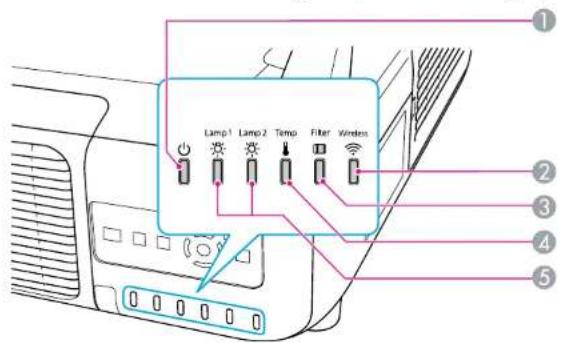
① Indicates the operating status. Standby condition
When the [∅] button is pressed in this condition, projection starts.
Preparing network monitoring (maximum approx. 20 seconds) or cool down in progress Buttons are disabled while the indicator is flashing.
Warming up Warm-up time is about 30 seconds. After warm-up is complete, the indicator stops flashing. [∅] button does not function during warm-up.
Projecting
② Indicates the operating status of wireless LAN when the optional wireless LAN unit is connected.
② Indicates the air filter status.
4 Indicates the internal temperature status.
Problem Solving

⑤ Indicates the projection lamps status.
Flashes green while Shutter or Blank is activated.
Refer to the following table to see what the indicators mean and how to remedy problems that they indicate.
If all indicators are off, check that the power cable is connected correctly and that the power is being supplied normally.
Sometimes, when the power cable is unplugged, the indicator remains lit for a short period, but this is not a fault.
Indicator is lit or flashing red
| Status Cause Remedy or Status | ||
| Internal Error | Stop using the projector, disconnect the power cable from the electrical outlet, and contact your local dealer or the nearest address provided in the Support and Service Guide. Epson Projector Contact List | |
| Fan ErrorSensor ErrorCool System Error | Stop using the projector, disconnect the power cable from the electrical outlet, and contact your local dealer or the nearest address provided in the Support and Service Guide. Epson Projector Contact List | |
| High Temp Error (overheating) | The lamps turn off automatically and projection stops. Wait for about five minutes. After about five minutes the projector switches to standby mode, so check the following two points.Check that the air filter and air exhaust vent are clear, and that the projector is not positioned against a wall.If the air filter is clogged, clean or replace it.p.98,p.104If the error continues after checking the points above, stop using the projector, disconnect the power cable from the electrical outlet, and contact your local dealer or the nearest address provided in the Support and Service Guide.Epson Projector Contact List | |
| When using at an altitude of 1500 m or more, set High Altitude Mode to On.p.57 | ||
| Set Direction to Pointing Down, Pointing Up, Angled Up, or Angled Down when the projector is installed in a direction which is not horizontal.p.57 | ||
| Lamp ErrorLamp Failure | Check the following two points.Take out the both lamps and check if they are cracked.p.101Clean the air filter.p.98 | |
| Status Cause Remedy or Status | |
| If it is not cracked: Re-fit the lamp and turn on the power.If the error continues: Replace the lamp with a new lamp and turn on the power.If the error continues: Stop using the projector, disconnect the power cable from the electrical outlet, and contact your local dealer or the nearest address provided in the Support and Service Guide. Epson Projector Contact List | |
| If it is cracked: Replace it with a new lamp, or contact your local dealer for further advice. If replacing the lamp yourself, be careful to avoid pieces of broken glass (you cannot continue projecting until the lamp is replaced). Epson Projector Contact List | |
| When using at an altitude of 1500 m or more, set High Altitude Mode to On. p.57 | |
| Set Direction to Pointing Down, Pointing Up, Angled Up, or Angled Down when the projector is installed in a direction which is not horizontal. p.57 | |
| Filter Airflow Error Check the following two points.Check that the air filter and air exhaust vent are clear, and that the projector is not positioned against a wall.If the air filter is clogged, clean or replace it. p.98, p.104If the error continues after checking the points above, stop using the projector, disconnect the power cable from the electrical outlet, and contact your local dealer or the nearest address provided in the Support and Service Guide. Epson Projector Contact List | |
| Auto Iris Error Cinema filter error Shutter Error Power Err. (Ballast) Stop using the projector, disconnect the power cable from the electrical outlet, and contact your local dealer or the nearest address provided in the Support and Service Guide. Epson Projector Contact List |
Indicator is flashing or lit

: Lit

Flashing

: Off

: Varies according to the projector status
| Status Cause Remedy or Status | ||
| High Temp WarningReplace Lamp | (This is not an abnormality. However, if the temperature rises too high again, projection stops automatically.)Check that the air filter and air exhaust vent are clear, and that the projector is not positioned against a wall.If the air filter is clogged, clean or replace it.p.98,p.104The lamp indicated by flashing indicator, lamp 1 or 2, is due for replacement. Replace it with a new lamp. p.101If you continue to use the lamp after the replacement period has passed, the possibility that the lamp may explode increases. Replace it with a new lamp as soon as possible.We recommend replacing both lamps together to maintain consistent hue and brightness of projected images. | |
| Lamp WarningSupply System Warning(Ballast) | Check the following two points.Remove the lamp indicated by the flashing indicator, lamp 1 or 2, and check if it is cracked. p.101Clean the air filter. p.98 | |
| If it is not cracked: Re-fit the lamp and turn on the power.If the error continues: Replace the lamp with a new lamp and turn on the power.If the error continues: Stop using the projector, disconnect the power cable from the electrical outlet, and contact your local dealer or the nearest address provided in the Support and Service Guide.Epson Projector Contact List | ||
| If it is cracked: Replace it with a new lamp, or contact your local dealer for further advice. (Only one lamp is working. Replace the burned-out lamp as soon as possible.).Epson Projector Contact ListIf replacing the lamp yourself, be careful to avoid pieces of broken glass. | ||
| When using at an altitude of 1500 m or more, set High Altitude Mode to On. p.57 | ||
| Set Direction to Pointing Down, Pointing Up, Angled Up, or Angled Down when the projector is installed in a direction which is not horizontal. p.57 | ||
| No Air FilterAir Flow Sensor Err. | Check that the air filter is securely installed. p.104The projector automatically turns off about one minute after it detects that there is no air filter.If the error continues even though an air filter is installed, the air filter sensor may be defective. Stop using the projector, disconnect the power cable from the electrical outlet, and contact your local dealer or the nearest address provided in the Support and Service Guide.Epson Projector Contact List | |
| Low Air Flow (This is notAir Filter Notice | an abnormality. However, projection stops automatically if the airflow falls any further.)The message "The air filter is clogged. Clean or replace the air filter." is displayed. Check the following two points.Check that the air filter and air exhaust vent are clear, and that the projector is not positioned against a wall.If the air filter is clogged, clean or replace it. p.98, p.104If the Low Air Flow status continues after cleaning the air filter, replace the air filter with a new one. p.104If the error continues after checking the points above, stop using the projector, disconnect the power cable from the electrical outlet, and contact your local dealer or the nearest address provided in the Support and Service Guide.Epson Projector Contact List"Time to clean the air filter. Clean or replace the air filter." is displayed. Clean the air filter. p.98If the air filter is stained yellow with tobacco smoke and cannot be cleaned, replace it with a new one.The indicators or messages regarding "Air Filter Notice" are displayed only when Air Filter Notice is set to On, on the configuration menu's Extended menu. p.57 | |

- If the projector is not operating properly, even though the indicators are all showing normal, refer to "When the Indicators Provide No Help". p.88
- If the error is not indicated in this table, stop using the projector, disconnect the power cable from the electrical outlet, and contact your local dealer or the nearest address provided in the Support and Service Guide. Epson Projector Contact List
When the Indicators Provide No Help
If any of the following problems occur and the indicators do not offer a solution, refer to the pages given for each problem.
Problems relating to images
- "No images appear" p.89
Projection does not start, the projection area is completely black, the projection area is completely blue, and so on. - "Moving images are not displayed (only the moving image portion turns black)." p.89
Moving images being projected from a computer appear black and nothing is projected. - "Projection stops automatically" p.89
• "The message "Not supported" is displayed." p.90 - ""No Signal" is displayed." p.90
- "Images are fuzzy or out of focus" p.90
- "Interference or distortion appears in images" p.91
- "The image is truncated (large) or small, or the aspect is not suitable" p.91 Only part of the image is displayed, or the height and width ratios of the image are not correct, and so on.
- "Image colors are not right" p.92
The whole image appears purplish or greenish, images are black & white, colors appear dull, and so on... (Computer monitors and LCD screens have different color reproduction performance, so that the colors projected by the projector and the colors appearing on the monitor may not necessarily match, but this is not a sign of a problem.) - "Images appear dark" p.92
Problems when projection starts
- "No power supplied" p.93
Other problems
• "The Remote Control does not work" p.94
- "Nothing appears on the external monitor" p.94
- "I want to change the language for messages and menus" p.95
- "Mail is not received even if a problem occurs in the projector" p.95
- "The battery that saves your clock settings is running low." is displayed. p.95
Interpreting Event IDs
p.96
Problems relating to images
No images appear
| Check Remedy | |
| Did you press the [⏻] button? | Press the [⏻] button to turn the power on. |
| Are the indicators switched off? | The power cable is not connected correctly or power is not being supplied normally. Connect the projector's power cable correctly. ➕ Quick Start Guide Check that your electrical outlet or power source is functioning correctly. |
| Is Shutter active? | Press the [Shutter] button on the Remote Control to cancel Shutter. ➕ p.33 |
| Are the configuration menu settings correct? | Reset All of the settings. ➕ Reset Menu - Reset All p.79 |
| Is the projected image completely black? Only when projecting computer images | Some input images, such as screen savers, may be completely black. |
| Is the image signal format setting correct? Only when projecting images from a video source | Change the setting according to the signal for the connected equipment. ➕ Signal Menu - Video Signal p.53 |
Moving images are not displayed (only the moving image portion turns black).
| Check Remedy | |
| Is the computer's image signal being output to the LCD and the monitor?Only when projecting images from a laptop computer or a computer with a built-in LCD screen | Change the image signal to external output only. ➕ Check your computer's documentation. |
Projection stops automatically
| Check Remedy | |
| Is Sleep Mode set to On? | Press the [∅] button to turn the power on. If you do not want to use Sleep Mode, change the setting to Off. ➕ Extended Menu - Operation - Sleep Mode p.57 |
| Is the air filter installed? | Check that the air filter is securely installed. ➕ p.104The projector automatically turns off about one minute after it detects that there is no air filter. |
The message "Not supported" is displayed.
| Check Remedy | |
| Is the image signal format setting correct?Only when projecting images from a video source | Change the setting according to the signal for the connected equipment. 📄 Signal Menu - Video Signal p.53 |
| Do the image signal Resolution and the Refresh Rate correspond to the mode?Only when projecting computer images | Refer to the computer’s documentation for how to change the image signal Resolution and the Refresh Rate output from the computer. 📄 "Supported Monitor Displays" p.175 |
"No Signal" is displayed.
| Check Remedy | |
| Are the cables connected correctly? | Check that all the cables required for projection are securely connected. ➕ p.132, p.134 |
| Is the correct input port selected? | Change the image by pressing the [Source Search] button on the Remote Control or the Control panel. ➕ p.20 |
| Is the power for the computer or video source turned on? Turn the power on for the equipment. | |
| Are the image signals being output to the projector?Only when projecting images from a laptop computer or a computer with a built-in LCD screen | If the image signals are only being output to the computer's LCD monitor or to the accessory monitor, you need to change the output to an external destination as well as the computer's own monitor. For some computer models, when the image signals are output externally, they no longer appear on the LCD monitor or accessory monitor. ➕ p.133If the connection is made while the power of the projector or computer is already turned on, the function [Fn] key that changes the computer's image signal to external output may not work. Turn the power for the computer and the projector off and then back on again. |
Images are fuzzy or out of focus
| Check Remedy | |
| Is the focus adjusted correctly? | Make sure that at least 30 minutes has passed after the projection starts, and press the [Focus] button on the remote control to adjust the focus. ➕ Quick Start Guide , p.15 |
| Is the projector at the correct distance? | Is it projecting outside of the recommended projection distance range?Setup within the recommended range. ➕ p.171 |
| Is the Keystone adjustment value too large? | Lower the projection angle to reduce the amount of keystone correction. ➕ p.142 |
Problem Solving

| Check Remedy | |
| Has condensation formed on the lens? | If the projector is suddenly taken from a cold environment to a warm environment, or if sudden ambient temperature changes occur, condensation may form on the surface of the lens, and this may cause the images to appear fuzzy. Set the projector up in the room about one hour before it is used. If condensation forms on the lens, turn the projector off and wait for the condensation to disappear. |
Interference or distortion appears in images
| Check Remedy | |
| Is the image signal format setting correct?Only when projecting images from a video source | Change the setting according to the signal for the connected equipment. ➕ Signal Menu - Video Signal p.53 |
| Are the cables connected correctly? | Check that all the cables required for projection are securely connected. ➕ p.132, p.134 |
| Is an extension cable being used? | If an extension cable is used, electrical interference may affect the signals. Use the cables supplied with the projector to check if the cables you are using may be causing the problem. |
| Is the correct resolution selected?Only when projecting computer images | Set the computer so that the signals being output are compatible with the projector. ➕ "Supported Monitor Displays" p.175 ➕ Computer documentation |
| Are the "Sync." and "Tracking" settings adjusted correctly?Only when projecting computer analog RGB signals | Press the [Auto] button on the Remote Control or the [Enter] button on the Control panel to perform automatic adjustment. If the images are not adjusted correctly after using automatic adjustment, you can make the adjustments using Sync. and Tracking from the configuration menu. ➕ Signal Menu - Tracking, Sync. p.53 |
| Is the Resolution set to Manual?Only when projecting on a split screen | The image may be collapsed if the Resolution on the configuration menu and the resolution of the projected image are not the same.If the image is collapsed, set the Resolution to Auto. ➕ Signal Menu - Resolution p.53 |
The image is truncated (large) or small, or the aspect is not suitable
| Check Remedy | |
| Is the aspect adjusted correctly? | Press the [Aspect] button on the remote control to select an aspect suitable for the input source. p.22 |
| Is a wide panel computer image being projected?Only when projecting computer images | Change the setting according to the signal for the connected equipment. Signal Menu - Resolution p.53 |
| Is the image still being enlarged by E-Zoom? | Press the [Esc] button on the remote control to cancel E-Zoom. p.34 |
| Is Scale set to On? | Set Scale to Off on the configuration menu. Signal Menu - Scale p.53 |
Problem Solving

| Check Remedy | |
| Is Position adjusted correctly? | Press the [Auto] button on the remote control or the [Enter] button on the control panel to perform automatic adjustment when projecting the computer analog RGB signals. If the images are not adjusted correctly after using automatic adjustment, you can make the adjustments using Position from the configuration menu.Apart from computer analog RGB signals, you can adjust other signals while projecting by adjusting Position from the configuration menu. Signal Menu - Position p.53 |
| Is the computer set for dual display?Only when projecting computer images | If dual display is activated in the "Display Properties" of the computer's Control panel, only about half of the image on the computer screen is projected. To display the entire image on the computer screen, turn off the dual display setting.Computer video driver documentation |
| Is the correct resolution selected?Only when projecting computer images | Set the computer so that the signals being output are compatible with the projector."Supported Monitor Displays" p.175 Computer documentation |
Image colors are not right
| Check Remedy | |
| Do the input signal settings match the signals from the connected device? | Change the setting according to the signal for the connected equipment. ▶ Signal Menu - Input Signal, Video Signal p.53 |
| Is the image Brightness set correctly? | Adjust the Brightness setting from the configuration menu. ▶ Image Menu - Brightness p.51 |
| Are the cables connected correctly? | Check that all the cables required for projection are securely connected. ▶ p.132, p.134 |
| Is Contrast▶ adjusted correctly? | Adjust the Contrast setting from the configuration menu. ▶ Image Menu - Contrast p.51 |
| Is the Color Adjustment correctly? | Adjust the Advanced setting from the configuration menu. ▶ Image Menu - Advanced p.51 |
| Are the Color Saturation and Tint adjusted correctly?Only when projecting images from a video source | Adjust the Color Saturation and Tint settings from the configuration menu. ▶ Image Menu - Color Saturation, Tint p.51 |
Images appear dark
| Check Remedy | |
| Is the image Brightness set correctly? | Adjust the Brightness and Power Consumption settings from the configuration menu. ➕ Image Menu - Brightness p.51 ➕ Settings Menu - Power Consumption p.55 |
| IsContrast▶adjusted correctly? | Adjust the Contrast setting from the configuration menu. ➕ Image Menu - Contrast p.51 |
| Is the lamp due for replacement? | When the lamp is nearly ready for replacement, the images become darker and the color quality becomes poorer. When this happens, replace the lamp with a new lamp. p.101 |
| Is Multi-Projection set to On? | Brightness Level or Brightness Correct. on Multi-Projection could be set.If not projecting from multiple projectors, set Multi-Projection to Off. Extended Menu - Multi-Projection p.57 |
Problems when projection starts
No power supplied
| Check Remedy | |
| Did you press the [⏻] button? | Press the [⏻] button to turn the power on. |
| Are the indicators switched off? | The power cable is not connected correctly or power is not being supplied normally.Disconnect and then reconnect the power cable. ➕ Quick Start GuideCheck that your electrical outlet or power source is functioning correctly. |
| Do the indicators turn on and off when the power cable is touched? | There is probably a poor contact in the power cable, or the power cable may be defective. Reinsert the powercable. If this does not solve the problem, stop using the projector, disconnect the power cable from the electrical outlet, and contact your local dealer or the nearest address provided in the Support and Service Guide. ➕ Epson Projector Contact List |
| Is Control Panel Lock set to Full Lock? | Press the [⏻] button on the Remote Control. If you do not want to use Control Panel Lock, change the setting to Off. ➕ Settings Menu - Control Panel Lock p.55 |
| Is the correct setting for the remote receiver selected? | Check the Remote Receiver from the configuration menu. ➕ Settings Menu - Remote Receiver p.55 |
| Was the power cable plugged back in or was the breaker turned on immediately after Direct Power Off? | When the operation to the left is performed when Direct Power On is set to On, the power may not turn back on. Press the [⏻] button to turn the power back on. |
| Is the ID switch on the side of the remote control set to On? | When the switch is set to On, you can use the remote control to operate only a projector with a matching ID. Set ID switch to Off. ➕ p.152 |
| Are the lamp cover and lamps installed correctly? | If the lamp or lamp cover is installed incorrectly, the projector cannot be turned on. Check how it is installed. ➕ p.101 |
Other problems
The Remote Control does not work
| Check Remedy | |
| Is the remote control light-emitting area pointing towards the remote receiver on the projector when it is operated? | Point the remote control towards the Remote Receiver. p.18 |
| Is the remote control too far from the projector? | The operating range for the remote control is about 15 m. p.18 |
| Is direct sunlight or strong light from fluorescent lamps shining onto the Remote Receiver? | Set the projector up in a location where strong light does not shine onto the remote receiver. Or set the remote receiver to Off from Remote Receiver in the configuration menu. Settings Menu - Remote Receiver p.55 |
| Is the correct setting for the remote receiver selected? | Check the Remote Receiver from the configuration menu. Settings Menu - Remote Receiver p.55 |
| Are the batteries dead or have the batteries been inserted correctly? | Make sure the batteries are inserted correctly or replace the batteries with new ones if necessary. p.16 |
| Are the remote control ID and the projector ID matched? | Make sure the ID for the projector you want to operate and the ID for the remote control match. To operate all projectors by remote control regardless of the ID setting, set the ID switch on the side of the remote control to Off. p.150 |
| Does Remote Control Type match the remote control that you are using? | Check the Remote Control Type on the configuration menu. Extended Menu - Operation - Remote Control Type p.57 |
| Is the optional remote control cable connected to the remote control or to the projector's Remote port? | When the remote control cable is connected, the remote control light-emitting area or the projector's remote receiver are disabled. When not using the remote control cable set, disconnect it from the remote control and the Remote port. |
| Is the remote control button lock set? | When the remote control button lock is set, buttons except for those needed for basic remote control operations are deactivated. Hold down the [Help] button to cancel the remote control button lock. p.42 |
Nothing appears on the external monitor
| Check Remedy | |
| Are images input from a port other than the Computer BNC input port? | Only RGB signals from the Computer input port or the BNC input port can be displayed on an external monitor. |
| Are you projecting a split screen? | Only RGB signals projected on the left screen from the Computer input port or the BNC input port can be displayed on an external monitor. p.29 |
I want to change the language for messages and menus
| Check Remedy | |
| Change the Language setting. | Adjust the Language setting from the configuration menu. ➕ Extended Menu - Language p.57 |
The authentication setting of wireless LAN fails
| Check Remedy | |
| Is the time set correctly? | If the wireless LAN is set correctly but the authentication setting fails, the time may not be set correctly. Check if it is set correctly. ➕ Extended Menu - Time/Schedule Settings p.57 |
Mail is not received even if a problem occurs in the projector
| Check Remedy | |
| Is Standby Mode set to Communication On? | To use the Mail Notification function when the projector is in standby, set Communication On in Standby Mode from the configuration menu. ➕ Extended Menu - Standby Mode p.57 |
| Did a fatal abnormality occur and the projector come to a sudden stop? | When the projector comes to a sudden stop, e-mail cannot be sent.If the abnormal state continues, contact your local dealer or the nearest address provided in the Support and Service Guide. ➕ Epson Projector Contact List |
| Is power being supplied to the projector? | Check that your electrical outlet or power source is functioning correctly. |
| Is Mail Notification function set correctly in the configuration menu? | Mail notification of problems is sent according to the settings on the Mail Notification menu in the configuration menu. Check if it is set correctly. ➕ Network Menu - Mail Notification Menu p.73 |
"The battery that saves your clock settings is running low." is displayed.
| Cause Remedy | |
| The internal power supply that saves your clock settings running low. | iContact your local dealer or the nearest address provided in the Support and Service Guide. ➕ Epson Projector Contact List |
Interpreting Event IDs
Check the event ID and perform the remedy given below. If the problem cannot be solved, contact the network administrator or one of the following contact addresses. Epson Projector Contact List
| Event ID Cause | Remedy | |
| 04320435 | Failed to startup EasyMP Network Projection. Restart the projector. | |
| 0434048104820485 | Network communication is unstable. | Check the status of network communications. Wait for a while and then try connecting again. |
| 0433 | An image that was transferred cannot be reproduced. | Restart EasyMP Network Projection. |
| 0484 Communications was cut off from the computer. | ||
| 04FE | EasyMP Network Projection ended unexpectedly. | Check the status of network communications. Restart the projector. |
| 04FF A system error occurred in the projector. Restart the projector. | ||
| 0891 | The same SSID access point cannot be found. | Set the computer, the access point, and the projector to the same SSID. |
| 0892 | The WPA and WPA2 authentication methods are not the same. | Check the setting of wireless LAN security to see if it is correct. ➕ Network Menu - Security Menu p.66 |
| 0893 The WEP, TKIP, and AES encoding methods are not the same. | ||
| 0894 Communications was cut off because a connection was made to the wrong access point. | Check with the network administrator and follow their instructions. | |
| 0898 | Failed to obtain the DHCP. | Check the DHCP server to see if it is operating correctly and check the LAN cable to see if it is connected correctly. Turn off DHCP if it is not being used. ➕ Network Menu - Wireless LAN Menu p.63, Wired LAN Menu p.70 |
| 0899 | Other connection errors | If the problem cannot be solved by restarting the projector or EasyMP Network Projection, contact one of the following contact addresses. ➕ Epson Projector Contact List |
| 089A | The EAP authentication type is not the same. | Check the setting of wireless LAN security to see if it is correct. Also, check if the certificate is imported correctly. ➕ Network Menu - Security Menu p.66 |
| 089B EAP server authentication failed. | ||
| 089C | EAP client authentication failed. | |
| 089D | Key exchange failed. | |

Maintenance
This chapter explains the maintenance methods that are required to ensure a long projector service life.
Cleaning

You should clean the projector if it becomes dirty or if the quality of projected images starts to deteriorate.

Warning
Do not use sprays containing a flammable gas to remove dirt or dust which is adhering to parts such as the lens or filter of the projector. This could be a cause of the fire for the high temperature of the lamps inside the unit.
Cleaning the Projector's Surface
Clean the projector's surface by wiping it gently with a soft cloth.
If the projector is particularly dirty, moisten the cloth with water containing a small amount of neutral detergent, and then firmly wring the cloth dry before using it to wipe the projector's surface.
Attention
Do not use volatile substances such as wax, alcohol, or thinner to clean the projector's surface. The quality of the case may change or become discolored.
Cleaning the Lens
Use a commercially available cloth for cleaning glasses to gently wipe the lens.
Attention
Do not rub the lens with harsh materials or subject the lens to shocks, as it can easily become damaged.
Cleaning the Air Filter
Clean the air filter and the air intake vent when the following message is displayed or the Filter indicator is flashing green.
Time to clean the air filter.
Clean or replace the air filter.
Attention
- If dust collects on the air filter it can cause the internal temperature of the projector to rise, and this can lead to problems with operation and shorten the optical engine's service life. Clean the air filter immediately when the message is displayed.
- If the air filter is stained yellow with tobacco smoke, it cannot be cleaned. In this case, replace it with a new air filter. p.104
- Do not rinse the air filter in water. Do not use detergents or solvents.
- When using a brush for cleaning, use one with long soft bristles, and brush it lightly. If it is brushed too strongly, dust will be ground into the air filter and cannot be removed.
Procedure

After you turn off the projector's power and the confirmation buzzer beeps twice, disconnect the power cable.

Remove the air filter cover.
Grip the air filter cover tab between your fingers, and pull up and remove the cover while pressing the tab.
Cleaning

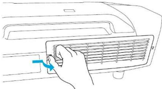
natural_image
Line drawing of a hand inserting a component into a grating machine (no text or symbols)
Remove the air filter.
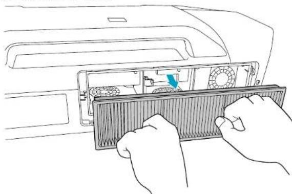
natural_image
Line drawing of hands installing a rack-mounted fan into a computer (no text or symbols)
With the front (the side with tabs) of the air filter facing down, tap the air filter four or five times to shake off the dust.
Turn it over and tap the other side in the same way.
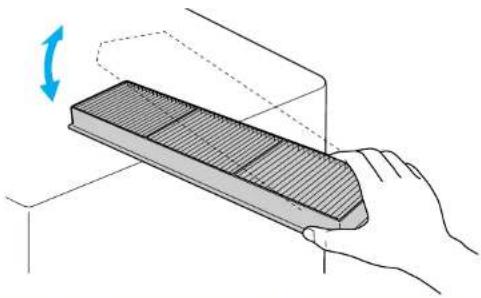
natural_image
Illustration of a hand holding a rectangular object with a curved arrow indicating rotation (no text or symbols)Attention
If the air filter is hit too hard, it may become unusable due to deformities and cracks.

Remove any dust remaining on the air filter by using a vacuum cleaner from the front side.
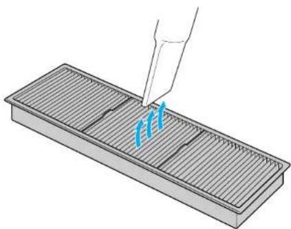
natural_image
Illustration of a pipette dispensing blue liquid into a grid-lined rack (no text or symbols)
Replace the air filter.
Cleaning

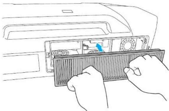
natural_image
Line drawing of hands installing a ventilation grille into a rack inside a computer (no text or symbols)
Replace the air filter cover.
Press until it clicks into place.
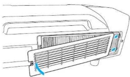
natural_image
Diagram of a car air vent with airflow arrows indicating airflow direction (no text or symbols)
If a message is frequently displayed, even after cleaning, it is time to replace the air filter. Replace it with a new air filter. p.104
Replacing the Lamps
Lamp replacement period
It is time to replace the lamp when:
- The message "Replace the lamp." is displayed at the lower left of the projection screen when you start projecting.
natural_image
Blank white image with a single gray rectangular shape in the bottom left corner (no text or symbols)• The lamp indicator flashes orange.
Replace the lamp indicated by the flashing indicator, either lamp 1 or 2.
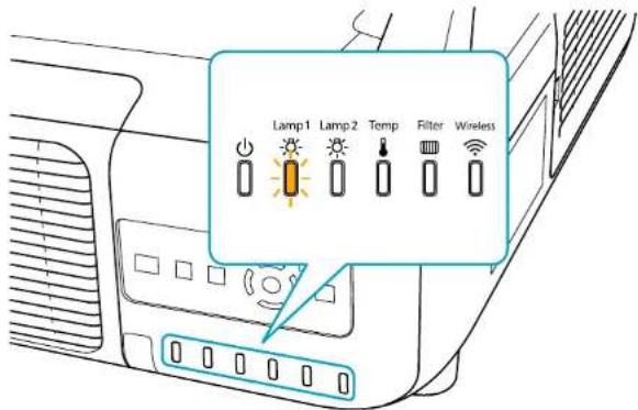
- The projected image gets darker or starts to deteriorate.
Attention
- The lamp replacement message is set to appear after the following time periods in order to maintain the initial brightness and quality of the projected images EB-Z8455WU/Z8450WU/Z8355W/Z8350W/Z10005/Z10000 When using Power Consumption continually at Normal 1: About TBD hours When using Power Consumption continually at ECO: About TBD hours EB-Z8150: About TBD hours
- Do not turn the projector on immediately after turning it off. Turning the projector on and off frequently may shorten the life of the lamps.
- If you continue to use the lamp after the replacement period has passed, the possibility that the lamp may explode increases. When the lamp replacement message appears, replace the lamp with a new one as soon as possible, even if it is still working.
- Depending on the characteristics of the lamp and the way it has been used, the lamp may become darker or stop working before the lamp warning message appears. We recommend that you keep a replacement lamp on hand at all times.

We recommend that you clean the air filter whenever you replace the lamp. p.98
Replace the air filter if it is discolored or if a message appears even after cleaning the air filter. p.104
How to replace the lamp
The lamps can be replaced even when the projector is suspended from a ceiling.

Warning
- When replacing the lamps because they have stopped illuminating, there is a possibility that the lamp may be broken. If replacing the lamp of a projector which has been installed on the ceiling, you should always assume that the lamp is broken, and you should stand to the side of the lamp cover, not underneath it. Remove the lamp cover gently.
- Never disassemble or remodel the lamp. If a remodeled or reassembled lamp is installed into the projector and used, it could cause a fire, electric shock, or an accident.

Caution
Wait until the lamps have cooled down sufficiently before removing the lamp cover. If the lamp is still hot, burns or other injuries may result. It takes about one hour after the power has been turned off for the lamp to be cool enough.
Procedure

After you turn off the projector's power and the confirmation buzzer beeps twice, disconnect the power cable.

Wait until the lamps have cooled down sufficiently before removing the lamp cover on the back of the projector.
Pinch the tabs on the front of the lamp cover together to release the lock. When the lock releases, pull the cover straight out.
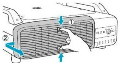

Pull up the lock lever for the lamp you want to replace and pull the lamp straight out.
If the lamp is cracked, replace it with a new lamp, or contact your local dealer for further advice. 🚙 Epson Projector Contact List
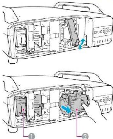
① Lamp 1
Replacing Consumables

② Lamp 2

Install the new lamp.
Insert the lamp along the guide rail in the correct direction so that it fits in place and press it firmly to the back. Pull down the lock lever until it clicks into place.
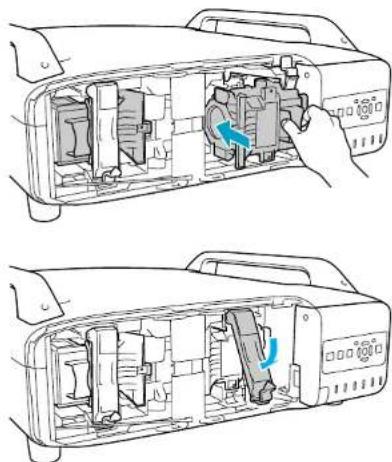
natural_image
Two technical diagrams of a printer's internal components, showing part assembly and adjustment (no text or symbols)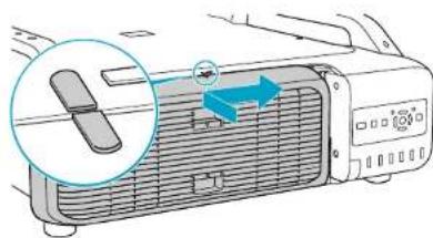
natural_image
Diagram of a car air conditioner unit with a magnified view showing the internal structure (no text or symbols)Attention
- Make sure you install the lamp securely. If the lamp cover is removed, the lamps turn off automatically as a safety precaution. If the lamp or the lamp cover is not installed correctly, the lamp will not turn on.
- This product includes a lamp component that contains mercury (Hg). Please consult your local regulations regarding disposal or recycling. Do not dispose of it with normal waste.
Resetting the Lamp Hours
The projector records how long the lamps are turned on and a message and indicator notify you when it is time to replace the lamp. After replacing the lamps and turning on the power, the following message is displayed on the screen and you can reset the lamp-hour counter.

Replace the lamp cover.
Press the cover against the unit and slide it to the right until it clicks.
Replacing Consumables

104
Select Yes, and then press the Enter button.
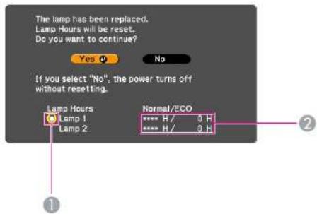
① Displays the replacement for the lamp 1.
② Displays the cumulative lamp operating time. If you select Yes and reset the Lamp Hours, the count for lamp 1 is set to 0H.
Replacing the Air Filter
Air filter replacement period
It is time to replace the air filter when:
• The air filter is discolored.
- The message is displayed even though the air filter has been cleaned.
How to replace the air filter
The air filter can be replaced even when the projector is suspended from a ceiling.
Procedure
1 After you turn off the projector's power and the confirmation buzzer beeps twice, disconnect the power cable.
② Remove the air filter cover.
Grip the air filter cover tab between your fingers, and pull up and remove the cover while pressing the tab.
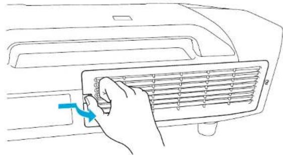
natural_image
Line drawing of a hand inserting a fan into an air conditioner cover (no text or symbols)③ Remove the air filter.
Replacing Consumables

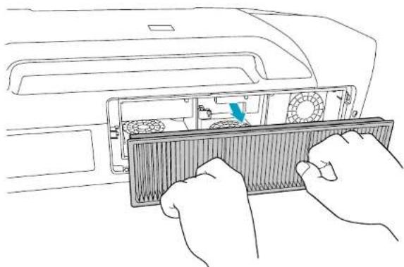
natural_image
Line drawing of hands installing a ventilation grater into a rack (no text or symbols)
Install the new air filter.
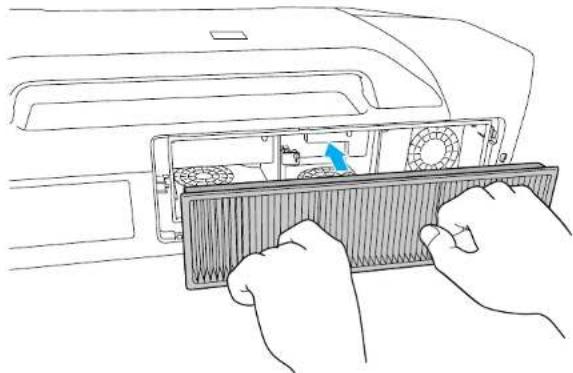
natural_image
Line drawing of hands installing a fan into a rack inside a vehicle (no text or symbols)
Replace the air filter cover.
Press until it clicks into place.
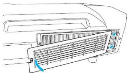
natural_image
Line drawing of a car air vent with airflow direction indicator (no text or symbols)
Dispose of used air filters properly in accordance with your local regulations.
Material of the frame part: Polypropylene
Material of the filter part: Polypropylene
Notes on Transportation

106
There are many glass parts and precision components inside the projector. To prevent damage due to impacts when transporting, handle the projector as follows.
Notes when packing and transporting
Enclose the projector securely in buffer material to protect it from shock, and place it into a strong cardboard container. Be sure to notify the carrier company that the contents are fragile.
Moving Nearby
Checking the following points, and then carry carefully by the handles.
- 'Turn off the power to the projector and disconnect all cables.
- Attach the cover to the lens.

Caution
Do not carry the projector by one person. Two people are needed to unpack or carry the projector.
When Transporting
Preparing packaging
After checking the points in "Moving Nearby", prepare the following and then pack up the projector.
- Remove the lens unit if an option lens, other than the standard zoom lens, is installed. Attach the standard zoom lens if the projector has a built-in lens. If the projector does not have a lens, attach the cover that was on the lens mount when you purchased the projector.
- The vertical and horizontal lens shifts are positioned in the center.
- Fit the protective lens pad that was used at the time of purchase.

Monitoring and Controls
This chapter explains the functions that can be used to monitor and control the projector.
EasyMP Monitor

EasyMP Monitor lets you carry out operations such as checking the statuses of multiple Epson projectors that are connected to a network at a computer monitor, and controlling the projectors from the computer.
Download the EasyMP Monitor software from the following website.
http://www.epson.com
Following are brief descriptions of the monitoring and control functions that can be carried out using EasyMP Monitor.
- Registering projectors for monitoring and control
Projectors on the network can be searched for automatically, and you can then select projectors to be registered from the projectors that are detected.
You can enter the IP addresses for target projectors to register them.
- Registered projectors can also be assigned to groups so that they can be monitored and controlled in groups.
• Monitoring the statuses of registered projectors
The power status (ON/OFF) for projectors and problems or warnings requiring attention can be checked visually by means of icons.
You can select groups of projectors or a single projector that you are interested in, and then check the cumulative lamp operating time or the details of information such as input sources, problems, and warnings for these projectors.
• Controlling registered projectors
Projectors can be selected in groups or as single projectors, and you can then carry out operations for the selected projectors such as turning the power on and off and switching their input sources.
Web Control functions can be used to change the settings in the projector's configuration menu.
If there are certain control actions which are carried out regularly at particular times or on particular days, you can use Timer Settings to register timer settings.
- Mail Notification settings
You can set e-mail addresses to which notifications are sent if a status requiring attention, such as a problem, occurs with a projector that has been registered.
- Sending messages to registered projectors
The Message Broadcasting plugin for EasyMP Monitor can be used to send JPEG files to registered projectors. p.122
Changing Settings Using a Web Browser (Web Control)

109
You can make Configuration menu settings and control the projector by using the Web browser of a computer that is connected to the projector via a network. Setup and control operations can be performed remotely if this function is used. In addition, you can use the computer's keyboard, so it is easier to enter characters needed for setup, such certificate settings.
Use Microsoft Internet Explorer 6.0 or later as the Web browser. If using a Mac OS, use Safari or Firefox.

- When communicating with a wireless LAN, connect in Advanced mode. p.63
- Setup and control with a Web browser are possible if Standby Mode is set to Communication On from the Extended menu of the projector's Configuration menu, even if the projector is in standby state (when the power is 0.71)p.57
Displaying Web Control
Use the following procedure to display Web Control.

- If your Web browser is set up to connect via a proxy server, Web Control cannot be displayed. To use Web Control, you need to make network connection settings with a device other than a proxy server.
- When setting the security using Web Control, we recommend setting Secure HTTP to On. p.71, "Secure HTTP Notes"
Procedure

Start the Web browser on the computer.

Enter the IP address of the projector in the address input box of the Web browser, and press the Enter key on the computer's keyboard.
Web Control is displayed.
When Web Control Password is set in the Network menu from the projector's Configuration Menu, enter the Password. Enter EPSONWEB as the user name. Enter the characters set for the web control password as the password. The default password is admin.
Displaying Web Remote
The Web Remote function allows you to perform projector remote control operations from a Web browser.
Procedure

Display Web Control. "Displaying Web Control" p.109

Click Web Remote.
Example: Web browser of a computer
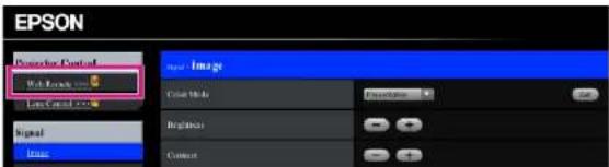

The Web Remote screen appears.
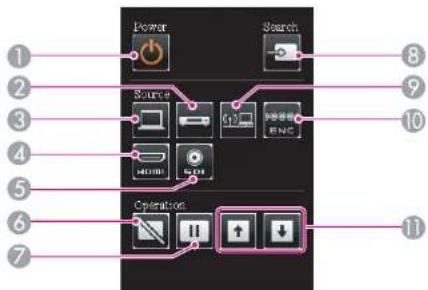
| Name Function | ||
| 1 | [∅] button | Turns the projector power On or Off. |
| 2 | [Video] button | Each time the button is pressed, the image displayed changes between the Video input port and S-Video input port. |
| 3 | [Computer] button | The input source will change to Computer. |
| 4 | [HDMI] button | Each time the button is pressed, the image displayed changes between the HDMI1 input port and HDMI2 input port. |
| 5 | [SDI] button | The input source will change to SDI. (EB-Z8455WU/Z8450WU only) |
| 6 | [Shutter] button | Turns the video on or off. p.33 |
| 7 | [Freeze] button | Images are paused or unpaused. p.33 |
| 8 | [Search] button | Changes to the next input source that is connected to the projector and is sending an image. p.20 |
| 9 | [LAN] button | The input source will change to LAN. |
| 10 | [BNC] button | The input source will change to BNC. |
| 11 | [Page] buttons [+] [+] | These buttons can be used to page up and down when projecting an image from a computer that is connected to the projector through the network. |
Displaying Lens Control
The Lens Control function allows you to operate the projector's lens from a web browser.
Procedure

Display Web Control. "Displaying Web Control" p.109

Click Lens Control. Example: Web browser of a computer
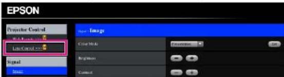

The Lens Control screen appears.
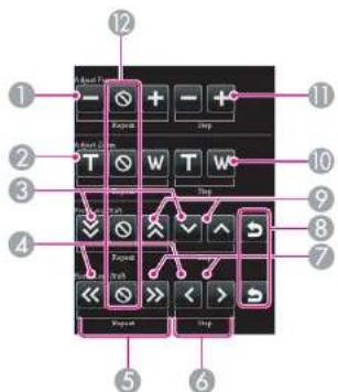
| Name Function | ||
| 1 | [Scale down] button | Adjusts the focus. |
| 2 | [Tele] button | Reduces the image without changing the projection size. |
| 3 | [Down] button | Shifts the lens downward. |
| 4 | [Left] button | Shifts the lens leftward. |
| 5 | [Repeat] button | Continues adjusting until the [Stop] button is pressed. |
| 6 | [Step] button | Adjusts by one step each time the button is pressed. |
| 7 | [Right] button | Shifts the lens rightward. |
| 8 | [Default Shift] button | Reset the default for the lens shift adjustment. |
| 9 | [Up] button | Shifts the lens upward. |
| 10 | [Wide] button | Enlarges the image without changing the projection size. |
| 11 | [Scale Up] button | Adjusts the focus. |
| 12 | [Stop] button | Stops the adjustment. |
Setting Certificates
You can use a web browser to set the certificate settings used for wireless LAN authentication.
Install the following certificates in the projector: Client Certificate and CA certificate for wireless LAN security settings, and Web Server Certificate for the Secure HTTP function.
Procedure
1 Display Web Control. "Displaying Web Control" p.109
2 Click Network menu - Administrator Settings - Manage Certificates.
③ The Manage Certificates screen appears.
| Sub Menu Items/Values | |
| Client Certificate | Refresh/Clear |
| Issued to | |
| Issued by | |
| Validity period | |
| CA certificate | Refresh/Clear |
| Issued to | |
| Issued by | |
| Validity period | |
| Self-signed Certificate | Refresh/Clear |
| Issued to | |
| Issued by | |
| Validity period | |
Changing Settings Using a Web Browser (Web Control)

| Sub Menu Items/Values | |
| Web Server Certificate | Refresh/Clear |
| Issued to | |
| Issued by | |
| Validity period | |

When installing a certificate, make sure the projector supports its format. "Supported Certificates" p.177
Secure HTTP Notes
When Secure HTTP is set to On, security using HTTPS protocol is automatically applied between the projector and web browser of the computer connected to the network. You can use this function for secure communication between the projector and Web browser.
A certificate is used in communication using HTTPS protocol, to certify reliability of the server. The projector automatically makes internally and communicates its self-signed certificate. This self-signed certificate cannot verify reliability from a computer's web browser, so it shows a warning on reliability of the server when you access from a web browser. Ignore this warning.
You can separately create a server certificate which can be verified from a computer's web browser, and install it in the projector to prevent this warning. "Supported Certificates" p.177
Using the Mail Notification Function to Report Problems

By setting the Mail Notification function from the projector's
Configuration Menu, notification messages will be sent to the preset email addresses when a problem or warning occurs with a projector. This will enable the operator to be notified of problems with projectors even at locations away from the projectors. Network Menu - Administrator Settings - Mail Notification p.73

- Up to three notification destinations (Addresses) can be recorded, and notification messages can be sent to all three destinations at once.
- If a projector develops a critical problem and suddenly stops working, it may not be able to send a message notifying an operator of the problem.
- Monitoring is possible if Standby Mode is set to Communication On from the Extended menu of the projector's Configuration Menu, even if the projector is in standby state (when the power is off). p.57
Reading Problem Mail Notification Function
When the Mail Notification function is set to On and a problem/warning occurs in the projector, the following e-mail is sent.
Sender: Email Address 1
Subject: EPSON Projector
Line 1: The name of the projector where the problem has occurred Line 2: The IP address set for the projector where the problem has occurred.
Line 3 and on: Details of the problem
The details of the problem are listed line by line. The following table shows the details that are given in the message for each item. To deal with problems/warnings, see "Reading the Indicators" p.83
| Message Cause (Problems/Warnings) | |
| Clean Air Filter Air Filter Notice | |
| Message Cause (Problems/Warnings) | |
| Fan related error Fan Error | |
| High-speed cooling in progress High Temp Warning | |
| Internal error Internal Error | |
| Internal temperature error High Temp Error(Overheating) | |
| Lamp cover is open. Lamp Cover | Open |
| Lamp out Lamp Error | |
| Lamp replacement notification Replace Lamp | |
| Lamp timer failure Lamp Failure | |
| Low Air Flow | Low Air Flow |
| Low Air Flow Error | Filter Airflow Error |
| No-signal | No SignalNo Signal is input to the projector. Checkthe connection status or check that thepower for the signal source is turned on |
| Power Err. (Ballast) | Power Err. (Ballast) |
| Sensor error | Sensor Error |
A (+) or (-) appears at the start of the message.
(+): A projector problem has occurred
(-): A projector problem has been dealt with
Management Using SNMP

By setting SNMP from the projector's configuration menu, notification messages are sent to preset e-mail addresses when a problem or warning occurs with a projector. This is useful when controlling projectors centrally at a point distant from them.p.71

- SNMP should be managed by a network administrator or someone who is familiar with the network.
- To use the SNMP function to monitor the projector, you need to install the SNMP manager program on your computer.
- The managing function using SNMP cannot be used via wireless LAN in Quick mode.
- Up to two destination IP addresses can be saved.
Serial Connection
- Connector shape: D-Sub 9-pin (male)
- Projector input port name: RS-232C
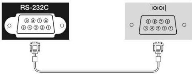
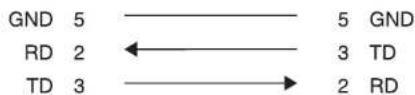
| Signal Name Function | |
| GND Signal wire ground | |
| TD Transmit data | |
| RD Receive data | |
Communications Protocol
- Default baud rate setting: 9600 bps
-
Data length: 8 bit
-
Parity: None
- Stop-bit: 1 bit
- Flow control: None
Command List
When the power ON command is transmitted to the projector, the power turns on and it enters warm-up mode. When the projector's power has turned on, a colon ":" (3Ah) is returned.
When a command is input, the projector executes the command and returns a "", and then accepts the next command.
If the command being processed terminates abnormally, an error message is output and a ":" is returned.
| Item Command | |||
| Power ON/OFF On | PWR ON | ||
| Off | PWR OFF | ||
| Signal selection | Computer | Auto | SOURCE 1F |
| RGB | SOURCE 11 | ||
| Component | SOURCE 14 | ||
| BNC | Auto | SOURCE BF | |
| RGB | SOURCE B1 | ||
| Component | SOURCE B4 | ||
| HDMI1 | SOURCE 30 | ||
| HDMI2 | SOURCE A0 | ||
| SDI (EB-Z8455WU/Z8450WU only) | SOURCE 60 | ||
| Video | SOURCE 45 | ||
| S-Video | SOURCE 42 | ||
| LAN | SOURCE 53 | ||
| Shutter Button Electric | Shutter/Blank | On MUTE ON | |
| Off MUTE OFF | |||
Add a Carriage Return (CR) code (0Dh) to the end of each command and transmit.
About PJLink

PJLink Class1 was established by the JBMIA (Japan Business Machine and Information System Industries Association) as a standard protocol for controlling network-compatible projector's as part of their efforts to standardize projector control protocols.
The projector complies with the PJLink Class1 standard established by the JBMIA.
It complies with all commands except for the following commands defined by PJLink Class1, and agreement was confirmed by the PJLink standard adaptability verification.
URL: http://pjlink.jbmia.or.jp/english/
• Non-compatible commands
| Function PJLink Command | |
| Image muting set AVMT 11 | |
- Input names defined by PJLink and corresponding projector sources
| Source PJLink Command | |
| Computer INPT 11 | |
| BNC INPT 13 | |
| Video INPT 23 | |
| S-Video INPT 22 | |
| HDMI1 INPT 32 | |
| HDMI2 INPT 33 | |
| SDI (EB-Z8455WU/Z8450WU only) INPT 34 | |
| LAN INPT 52 | |
- Manufacturer name displayed for "Manufacture name information query" EPSON
- Model name displayed for "Product name information query" EB-Z8450WU/Z8455WU/Z9750WU/B1575WU/PL Pro Z8450WU/Z8455WU EB-Z8350W/Z8355W/Z9850W/B1585W/PL Pro Z8350W/Z8355W EB-Z10000/Z10005/Z9900/B1500/PL Pro Z8250/Z8255 EB-Z8150/Z9800/PL Pro Z8150
About Crestron RoomView®

Crestron RoomView® is an integrated control system provided by Creston®. It can be used to monitor and control multiple devices connected on a network.
The Projector supports the control protocol, and can therefore be used in a system built with Crestron RoomView
Refer to the Creston website for details on Crestron RoomView. (Only English-language displays are supported.)
http://www.crestron.com
An overview of Crestron RoomView is provided below.
- Remote operation using a Web browser
A Projector can be operated from a computer window just like using remote control.
• Monitoring and control with application software
Crestron RoomView® Express or Crestron RoomView® Server Edition provided by Crestor® can be used to monitor devices in the system, to communicate with the help desk, and to send emergency messages. Refer to the following website for details. http://www.crestron.com/getroomview
This manual describes operating procedures in the computer window using a Web browser.

- Only single-byte alphanumeric characters and symbols can be entered.
- The following functions cannot be used while using the Crestron RoomView®.
Web Control p.109
Message Broadcasting (EasyMP Monitor plugin) - Controlling is possible if Standby Mode is set to Communication On from the Extended menu of the projector's configuration menu, even if the projector is in standby state (when the power is off).
p.57
^a Operating a Projector from a Computer Window
Displaying the operation window
Confirm the following before performing the procedure.
- Make sure the computer and projector are connected to the network. When communicating with a wireless LAN, connect in Advanced mode.
p.63
- Set Crestron RoomView to On on the Administrator Settings menu under the Network menu. Changes in projector settings take effect upon restarting. p.71
Procedure

Start the Web browser on the computer.

Enter the IP address of the projector in the address field of the Web browser, and press the Enter key on the keyboard.
The operation window will be displayed.
Using the operation window
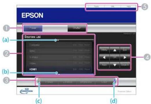
The following operations will be performed when the buttons are clicked.
| Button Function | |
| Power Turns the projector | power on or off. |
| Shutter You can use this when you want to focus the audience's attention on what you are saying, or if you do not want to show details such as when you are changing between files during presentations from a computer. p.33 | |
② Switch to the image from the selected input source. To display input sources that are not shown in the window, click (a) or (b) to scroll up or down. The source name can be changed optionally.
③ The following operations will be performed when the buttons are clicked. To display buttons that are not shown in the window, click (c) or (d) to scroll left or right.
| Button Function | |
| Freeze | Images are paused or unpaused. p.33 |
| Contrast Adjusts the difference between light and shade in the images. | |
| Brightness Adjusts the image brightness. | |
| Color Adjusts the color saturation for the images. | |
| Sharpness Adjusts the image sharpness. | |
| Zoom | Click the [∅] button to enlarge the image without changing the projection size. Click the [∅] button to reduce an image that was enlarged with the [∅] button. Click the [▲], [▼], [◀], or [▶] button to change the position of an enlarged image. p.34 |
4 Clicking the [▲], [▼], [◀], or [▶] button performs the same operation as the [◎] button on the remote control. The following operations will be performed when the other buttons are clicked.
| Button Function | |
| OK Performs the same operation as the [Enter] button on the remote control. p.15 | |
| Menu Displays and closes the configuration menu. | |
| Auto | If clicked when the computer analog RGB signals are being projected, automatically optimizes the image by adjusting the Tracking, Sync., and Zoom Position. |
| Search | Switches to the image from the input port where video signals are being input. p.20 |
| Esc | Performs the same operation as the [Esc] button on the remote control. p.15 |
⑤ The following operations will be performed when the tabs are clicked.
About Crestron RoomView®

| Tab Function | |
| Contact IT Help Displays the Help Desk window. Used to send and receive messages to the administrator using Crestron RoomView® Express. | |
| Info Displays information on the projector that is currently connected. | |
| Tools Changes the settings in the projector that is currently connected. Refer to the next section. | |
Using the tools window
The following window will be displayed if the Tools tab is clicked in the operation window. This window is used to change the settings in the projector that is currently connected.
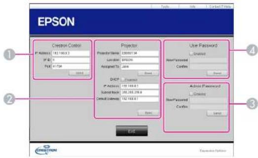
1 Crestron Control
Makes settings for Crestron® central controllers.
② Projector
The following items can be set.
| Item Function | |
| Projector Name | Enter a name to differentiate the projector that is currently connected from other projectors on the network. (The name can contain up to 15 single-byte alphanumeric characters.) |
| Location Enter an installation | location name for the projector that is currently connected on the network. (The name can contain up to 32 single-byte alphanumeric characters and symbols.) |
| Assigned To Enter a user name for the projector. (The name can contain up to 32 single-byte alphanumeric characters and symbols.) | |
About Crestron RoomView®

| Item Function | |
| DHCP | Select the Enabled check box to use DHCP. The following address cannot be set if DHCP is enabled. |
| IP Address | Enter the IP address to assign to the currently connected projector. |
| Subnet Mask Enter a subnet mask for the projector that is currently connected on the network. | |
| Default Gateway Enter the gateway address for the currently connected projector. | |
| Send Click this button to commit changes made to the Projector. | |
③ Admin Password
Select the Enabled check box to require a password to open the Tools window. The following items can be set.
| Item Function | |
| New Password Enter the new password when changing the password to open the Tools window. (The password can contain up to 26 single-byte alphanumeric characters.) | |
| Confirm | Enter the same password as you entered in New Password. If the passwords are not the same, an error will be displayed. |
| Send Click this button to commit changes made to the Admin Password. | |
4 User Password
Select the Enabled check box to require a password to open the operation window on the computer. The following items can be set.
| Item Function | |
| New Password Enter the new password when changing the password to open the operation window. (The password can contain up to 26 single-byte alphanumeric characters.) | |
| Confirm Enter the same password as you entered in New Password. If the passwords are not the same, an error will be displayed. | |
| Send Click this button to commit changes made to User Password. | |
About Message Broadcasting

Message Broadcasting is plugin software for EasyMP Monitor.
Message Broadcasting can be used to send a message (JPEG file) to project
on all Epson projectors or specified projectors connected on the network.
The data can be sent manually, or sent automatically using Timer Settings of EasyMP Monitor.
Download the Message Broadcasting software from the following website.
http://www.epson.com

Network Functions
This chapter explains the additional functions for networks.
Projecting with "Connect to a Network Projector"

124
"Connect to a Network Projector" is a standard function in Windows Vista and Windows 7. You can project images from the computer by detecting the projector on the network only by using a function of the OS without having to install any special software.
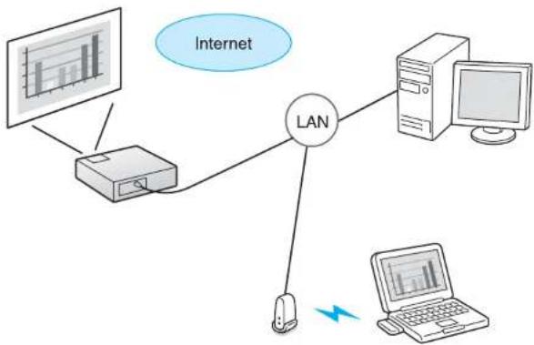
flowchart
graph TD
    Internet["Internet"] --> LAN["LAN"]
    LAN --> PC1["Computer"]
    LAN --> PC2["Laptop"]
    LAN --> PC3["Printer"]
    LAN --> PC4["Desktop"]
Compatible OS
Windows Vista: Home Premium/Business/Enterprise/Ultimate Windows 7: Professional/Ultimate
This section provides an easy explanation of "Connect to a Network Projector".
Check that the projector and computer are connected to the network, and carry out the following operations.
Procedure

Turn the projector on and switch the input source to LAN. ● "Changing the Projected Image" p.20

On the computer, start Windows, and then click "Start" - "All programs" - "Accessories" - "Connect to a Network Projector".
The connection setting screen is displayed.
The projector is identified by inputting its IP address, or by allowing the OS to automatically identify all of the connected projectors.

Once the OS has identified all of the connected projectors, select the one that you want to use and click "Connect".
When the projector password screen is displayed, enter the keyword shown at the bottom of the LAN standby screen.

- You can connect only one projector to a computer.
- When using Network Projector from Options in Windows Meeting Space, set the colors for the computer screen you are using to the highest level (32bit). If it is not capable of a 32bit display, a message is displayed and you cannot connect.
Making a WPS (Wi-Fi Protected Setup) Connection with a Wireless LAN Access Point

There are two methods for setting WPS
- Push Button Method SSID and security are set automatically when the Enter button is pressed on the projector's control panel and the dedicated button on the access point equipment. This method is recommended when the projector and access point are close together.
- PIN Code Method SSID and security are set automatically by inputting an 8-digit code that was assigned to the projector from the computer to the access point in advance. Make connection settings between the computer and the access point in advance. For details on how to make this connection, refer to the manual provided with the access point. This method is recommended when the projector is mounted on the ceiling.

Refer to the documentation for the access point device and to the following section when using any connection method other than WPS.
"Wireless LAN Menu" p.63
Connection Setup Method
Procedure

During projection, press the [Menu] button and select "Network" - "Network Configuration" from the configuration menu.
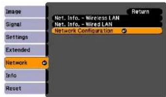
The Network Configuration screen is displayed.

From "Wireless LAN" select "To Setup Wizard".
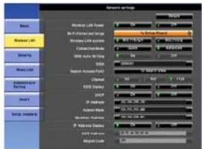
The following screen is displayed.
Making a WPS (Wi-Fi Protected Setup) Connection with a Wireless LAN Access Point

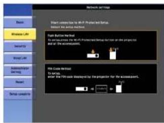
When connecting using the Push Button Method, follow the steps given below.
Go to "Making a connection using the PIN Code Method" when connecting using the PIN Code Method p.127
Making a connection using the push button method
Procedure

Select "Push Button Method".
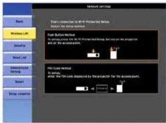
The "Push Button Method" screen is displayed.

Press the Enter button on the projector's control panel when prompted by the screen.
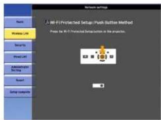
Then, the "Push Button Method" screen is displayed.

Press the button on the access point when prompted by the screen.
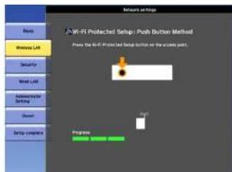
This completes the setup.

Press the Enter button or the Esc button.
It returns to the Wireless LAN menu screen.

Select "Setup complete" - "Yes."
Making a WPS (Wi-Fi Protected Setup) Connection with a Wireless LAN Access Point

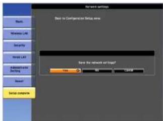
This completes the setup of the connection between the projector and the access point. Press the [Menu] button to close the configuration menu.
Making a connection using the PIN Code Method

Before you can make a connection using the PIN Code Method, a connection must have already been setup between the computer and the access point.
Procedure

Select "PIN Code Method".
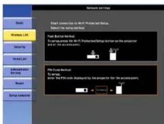
The "PIN Code Method" screen is displayed.

Enter the PIN code displayed on the "PIN Code Method" screen from the computer to the access point, and then select "Start Setup".
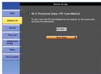
The progress is displayed.
Making a WPS (Wi-Fi Protected Setup) Connection with a Wireless LAN Access Point


The message "Setup by Wi-Fi Protected Setup complete." is displayed. Press the Enter button or the Esc button.
It returns to the Wireless LAN menu screen.

Select "Setup complete" - "Yes."
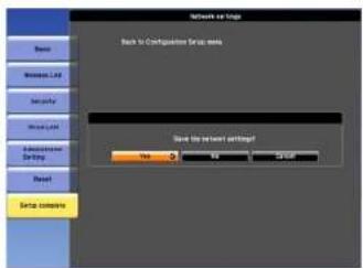
This completes the setup of the connection between the projector and the access point. Press the |Menu| button to close the configuration menu.

Installation and Connections
This chapter explains the projection installation methods and methods to connect to other equipment.
The projector can be mounted on a ceiling or placed on a desk as shown below. Also, it can be mounted at a tilted angle, so you can flexibly project images to various places.

Warning
- A special method of installation is required when suspending the projector from a ceiling (ceiling mount). If installation work is not carried out correctly, the projector could fall down. This may result in injury or accidents.
Contact your dealer or the nearest address provided in the Support and Service Guide if you want to use this installation method. Epson Projector Contact List - If you use adhesives on the Ceiling mount fixing points to prevent the screws from loosening, or if you use things such as lubricants or oils on the projector, the projector case may crack causing it to fall from its ceiling mount. This could cause serious injury to anyone under the ceiling mount and could damage the projector.
When installing or adjusting the Ceiling mount, do not use adhesives to prevent the screws from loosening and do not use oils or lubricants and so on. - When mounting the projector on the ceiling, be sure to arrange measures to prevent it from falling such as passing a wire through the handles.
Attention
- Do not use the projector upside down.
- Set the Direction properly in the configuration menu according to the angle of installation. p.57
- Using the projector at an improper angle or setting the configuration menu incorrectly causes malfunctions and shortens the operating life of optical parts.
- Suspend the projector from the ceiling and project images from in front of a screen. - Suspend the projector from the ceiling and project images from behind a translucent screen.
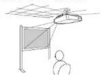
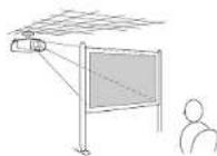
- Project images from in front of - Project images from behind a a screen. translucent screen.
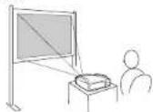
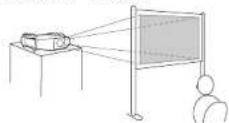
- Project images directly up
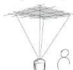
- Project images directly down
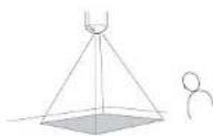
- Project images at angle
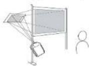
Installation Methods


- An optional ceiling mount is required when suspending the projector from a ceiling.
"Optional Accessories and Consumables" p.170
• The Projection setting can be changed from the configuration menu.
p.57
When installing the projector, keep enough distance from the wall to the projector's air exhaust and intake vent.
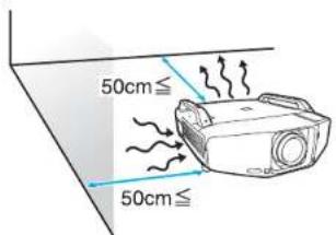
Connecting to Video Equipment

Observe the following precautions when connecting the projector to external equipment. Be sure to also read the documentation for the external equipment.
Attention
- Turn off the projector and the external equipment. The projector or external equipment may fail if they are connected while the power is on.
- Check the shapes of the cable connector and port before connecting them. If connecting them is attempted in the wrong direction or when they do not match, failure or equipment damage may occur.
Remove the interface cover before connecting external equipment. "Attaching and Removing the Interface Cover" p.166
Connecting to a Computer
This section provides examples of connecting the projector to a computer. The computer port and cable names may also be different from those given.

Refer to the following when projecting images from a computer that is connected through a network.
Projecting with the EasyMP Network Projection application software (provided with the projector) ▶ EasyMP Network Projection Operation Guide
Projecting with the EasyMP Multi PC Projection application software (provided with the projector) 📄 EasyMP Multi PC Projection Operation Guide
Projecting with the "Connect to a Network Projector" function provided with Windows Vista or Windows 7 p.124
| Computer port Connecting | cable Projector port | ||
Connection 1 Monitor Out port | 5BNC display cable (commercially available) BNC input port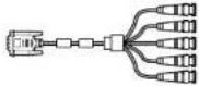 | 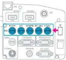 | |
Connection 2 Monitor Out port | Computer cable (supplied) Computer input port | 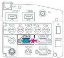 | |
| Connection 3 | HDMI output | HDMI cable (commercially available) | HDMI1/2 input port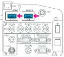 |

Use a cable that complies with the HDMI standard for the HDMI cable.
Changing the video output from a laptop computer.
When projecting images from a laptop computer connected to the projector with a computer cable, the output for the video signal must be changed at the computer. Refer to the documentation for your computer for the method to change the video output.
• Example of changing the output (Windows computers)
Hold down the [Fn] key on your computer and press the function key labeled CRT/LCD, ▲/□, and so on. If the image is not displayed on your computer monitor, press the same keys again.
Connecting to Video Equipment
This section provides examples of connecting the projector to video equipment. The video equipment port and cable names may also be different from those given.
| Port on the video equipment | Connecting cable Projector port | ||
| Connection 1 | Component outputs | RCA component video cable (commercially available) + BNC RCA adapter (commercially available)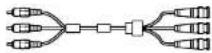 | CBNC input port (R/Cr/Pr, G/Y, B/Cb/Pb)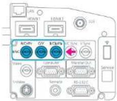 |
| Connection 2 | Component outputs Component cable | (D-sub/component conversion) (optional accessory)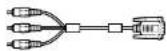 | Computer input port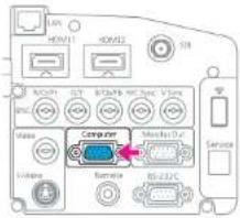 |
| Connection 3 | S-Video output | S-Video cable (commercially available) S-Video input port | 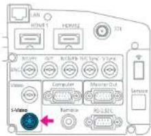 |
| Connection 4 | Video output | BNC video cable (commercially available) | Video input port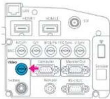 |
| Connection 5 | HDMI output | HDMI cable (commercially available) | HDMI1/2 input port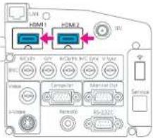 |
| Connection 6 | SDI output | BNC video cable (commercially available) | SDI input port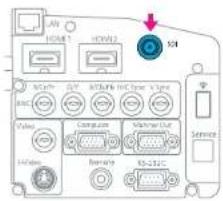 |
* EB-Z8455WU/Z8450WU only

- Set the Input Signal and Video Signal on the Signal menu according to the signal from the connected equipment. p.53
- Use a cable that complies with the HDMI standard for the HDMI cable.
Displaying a Test Pattern
A test pattern can be displayed to adjust the projection status without connecting video equipment. This is useful when installing a projector.

If the [User] button on the remote control is set to Test Pattern, the test pattern will be displayed when the [User] button is pressed. (The default setting is Test Pattern.)
Procedure

During projection, press the [Menu] button. Select Settings - "Test Pattern", then press the Enter button.
Using the Remote Control Using the Control Panel
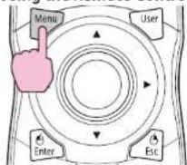
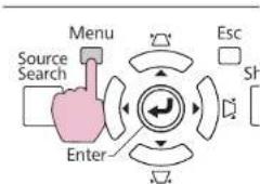
flowchart
graph TD
    A["Menu"] --> B["Source Search"]
    B --> C["Enter"]
    C --> D["Esc"]
    D --> E["Str"]
    style A fill:#f9f,stroke:#333
    style E fill:#bbf,stroke:#333
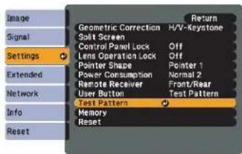

Press the [○] button on the remote control in the [→] direction or press the Enter button on the control panel to switch the test pattern.
To display the previous image, press the [button on the remote control in the ] direction.
Using the Remote Control Using the Control Panel
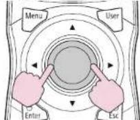
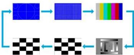
flowchart
graph TD
    A["Pixel Input"] --> B["Pixel"]
    B --> C["Color Filter"]
    C --> D["Gray Mask"]
    D --> E["Output"]
    F["Checkerboard"] --> G["Checkerboard"]
    G --> E
The following adjustments can be made while the test pattern is being displayed.
| Top Menu Sub Menu/Items | |
| Image menu | Color Mode p.28 |
| Abs. Color Temp. | |
| Advanced- Gamma p.146- RGB- RGBCMY p.146 | |
| Auto Iris | |
Adjusting the Projected Image

| Top Menu Sub Menu/Items | |
| Reset | |
| Signal menu Auto Setup | |
| Settings menu | Geometric Correction p.139 |
| Extended menu Multi-Projection | |
*1 Except for custom settings of gamma
*2 EB-Z8455WU/Z8450WU/Z8355W/Z8350W/Z10005/Z10000 only

To set menu items that cannot be set while the test pattern is being displayed or to fine-tune the projected image, project an image from the connected device.

Press the Esc button to end the test pattern.
Adjusting the Position of the Projected Image (Lens Shift)
The lens can be shifted to adjust the position of the projected image, for example, when the projector cannot be installed directly in front of the screen.
Procedure

Press the [Lens Shift] button on the Remote Control. When using the control panel of the projector, press the [Lens] button three times.
Using the Remote Control Using the Control Panel

To adjust the position of the projected image, use the [◎] button on the remote control or the □[▲], [□/▼], [□/◄], and [i/►] buttons on the control panel.
Using the Remote Control Using the Control Panel
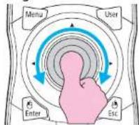
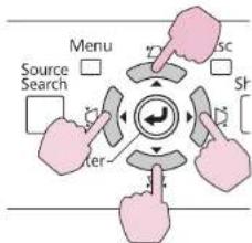
flowchart
graph TD
    A["Menu"] --> B["Source Search"]
    B --> C["Timer"]
    C --> D["Search Icon"]
    D --> E["Shr Icon"]
    E --> F["Arrow to Center"]
    style A fill:#f9f,stroke:#333
    style B fill:#ccf,stroke:#333
    style C fill:#cfc,stroke:#333
    style D fill:#fcc,stroke:#333
    style E fill:#cff,stroke:#333
    style F fill:#ffc,stroke:#333
Keep pressing the button to move the image continuously. When the position of the lens shift comes to the center of the vertical or horizontal direction, it stops moving. Release your finger and press the button again to adjust more.

The image will be clearest when both the vertical and horizontal lens shift are set in the center.
The ranges within which the image can be moved are shown below.
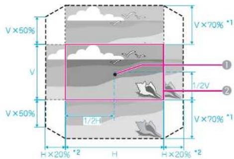
*1 EB-Z10005/Z10000/Z8150: V x 56%
*2 EB-Z10005/Z10000/Z8150: H x 6%
① Center of lens
② Projected image when lens shift is set in the center
The position of the projected image cannot be moved to the both horizontal and vertical maximum value.
Example: When the image is moved to the maximum value horizontally, that can be moved up to 50% vertically. When the image is moved to the maximum value vertically, the image cannot be moved horizontally.
Adjusting the Tilt of the Projected Image
When setting up on a desk, adjust the horizontal tilt of the projector with its front and rear feet.
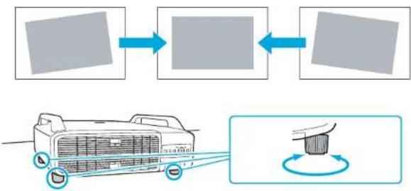
flowchart
graph LR
    A["Air Quality Inspection"] --> B{Exposure}
    B --> C["Exposure"]
    C --> D["Final Inspection"]
    D --> E["Car Air Quality Inspection"]
    E --> F["Car Air Quality Inspection with Sensor"]
Correcting Distortion in the Projected Image
There are four methods of correcting distortion in projected images as below.
- Quick Corner
This allows you to manually correct each of the four corners of the projected image separately. "Quick Corner" p.140
We recommend using Quick Corner to accurately adjust keystone distortion.
• H/V-Keystone
This allows you to manually correct distortion in the horizontal and vertical directions independently. You can perform easy H/V-Keystone corrections by using the / [ / ] [ / ] and [ / ] buttons on the projector's control panel. "H/V-Keystone" p.142
Adjusting the Projected Image

- Arc Correction Fine adjustment of the curved distortion caused by slack or shrinkage of the screen. "Arc Correction" p.143
- Point Correction Corrects slight distortion which occurs partially, or adjusts the screen position in an overlapping area when projecting from multiple projectors. "Point Correction" p.153
Quick Corner, H/V-Keystone, Arc Correction, and Point Correction cannot be performed at the same time. Select the correction method from Geometric Correction in the configuration menu. The default setting for Geometric Correction is set to H/V-Keystone, so when [△/▲], [▽/▼], [◇/◆], and [◇/▶] buttons are pressed, H/V-Keystone correction is carried out.
Because Quick Corner, H/V-Keystone, Arc Correction, and Point Correction can be carried out while projecting a test pattern, you do not need to make preparations by connecting a computer or other equipment.
Quick Corner
Procedure

During projection, press the [Menu] button. Select Settings menu - "Geometric Correction" and then press the Enter button. ▶ "Using the Configuration Menu" p.47
Using the Remote Control Using the Control Panel
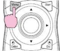
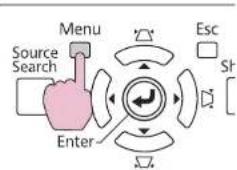
flowchart
graph TD
    A["Menu"] --> B["Source Search"]
    B --> C["Enter"]
    C --> D["Esc"]
    D --> E["St"]
    E --> F["Arrow to Center"]
    style A fill:#f9f,stroke:#333
    style B fill:#ccf,stroke:#333
    style C fill:#cfc,stroke:#333
    style D fill:#fcc,stroke:#333
    style E fill:#cff,stroke:#333
    style F fill:#ffc,stroke:#333
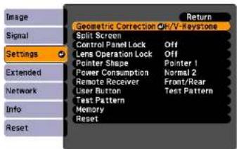

Select "Quick Corner", and then press the Enter button.
Press the Enter button again to display the selection screen from which you can select one of the four corners.
Adjusting the Projected Image

![[Quick Corner] Select the area.](/content/2026/05/815375/images/8623fda54aaa046bd49c2b31926436c6bf1ee021c4833da8fbd58bcb13eff13e.jpg)
Esc : Return (press for 2 seconds to
reset)

Use the [◇] button on the remote control or the [△/▲], [▽/
▼], [#/] and [#/] buttons on the control panel to select the corner you want to adjust, and then press the Enter button.
![[Quick Corner] Select the area.](/content/2026/05/815375/images/5887f64c41e2712e444aeef876f508d98e8ce37215587cbb077d4e08d5e2b834.jpg)

To adjust the shape, use the [◇] button on the remote control or the [□/▲], [□/▼], [‡/◄], and [□/►] buttons on the control panel.
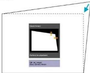
If the triangle in the direction you are adjusting the shape turns gray as shown in the screenshot below, you cannot adjust the shape any further in that direction.
![[Quick Corner] Cannot adjust any further.](/content/2026/05/815375/images/4c2310df9bff2b512e53837930796e4af338e89b946c111fd2557a7f033ac2df.jpg)
5 Repeat procedures 3 and 4 as needed to adjust any remaining corners.
6 When you are done, press the Esc button to exit the correction menu.
Because the correction method was changed to Quick Corner from Geometric Correction in the configuration menu, where
[∅/▼], [∅/▲], and [∅/▶] buttons are pressed later, the screen for selecting the corner in procedure 2 is displayed. Change Geometric Correction from the configuration menu to H/V-Keystone if you want to correct H/V-Keystone when pressing the/[▲], [∅/▼], [∅/▲], and [∅/▶] buttons on the control panel. p.55

If the Esc button is held down for about two seconds while correcting with Quick Corner, the confirm default reset screen is displayed.
Select "Yes" to reset the result of Quick Corner corrections.
H/V-Keystone
Procedure
Press the [☐/] [ ☐/] [ ☐/] and [ ☐/] buttons on the control panel to adjust keystone settings in the horizontal and vertical directions independently.

This adjustment can also be made from Geometric Correction - H/V-Keystone on the Settings menu. p.55
- Correcting vertical keystone
Vertical keystone can be corrected to a vertical projector tilt of up to 30° against the screen.
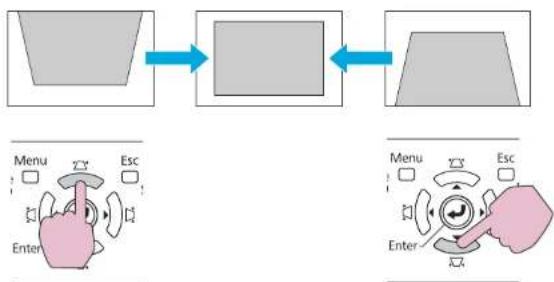
flowchart
graph LR
    A["Menu"] --> B["Esc"]
    B --> C["Enter"]
    C --> D["Next Step"]
    D --> E["Menu"]
    E --> F["Esc"]
    F --> G["Enter"]
If the [/] and [/] buttons are pressed simultaneously for at least 1 second, the value of horizontal keystone will return to the original status.
Adjusting the Projected Image

- Correcting horizontal keystone
Horizontal keystone can be corrected to a horizontal projector tilt of up to 20° against the screen.
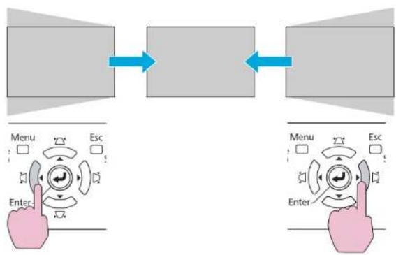
flowchart
graph LR
    A["Menu"] --> B["Esc"]
    B --> C["Enter"]
    C --> D["Menu"]
    D --> E["Esc"]
    E --> F["Enter"]
If the [◀/◀] and [◀/▶] buttons are pressed simultaneously for at least 1 second, the value of horizontal keystone will return to the original status.

Shift the lens to the position shown below when performing horizontal and vertical keystone. When the lens shift is not positioned as below, the distortion is not corrected accurately. "Adjusting the Position of the Projected Image (Lens Shift)" p.138
• The horizontal lens shift is set to the center.
• The vertical lens shift is set to the top or bottom.
The correction may not be properly performed according to the zoom adjustment value. And, the projected screen size may become smaller after performing the correction. Be careful about the projection distance when installing the projector.
Correct the image using Quick Corner to precisely align the projected image with the screen or to fine-tune the image. "Quick Corner" p.140
Arc Correction
Procedure

During projection, press the [Menu] button. Select Settings menu - "Geometric Correction" and then press the Enter button. ▶ "Using the Configuration Menu" p.47
Using the Remote Control Using the Control Panel
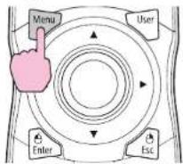
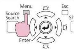
flowchart
graph TD
    A["Menu"] --> B["Source Search"]
    B --> C["Enter"]
    C --> D["Esc"]
    D --> E["St"]
Adjusting the Projected Image

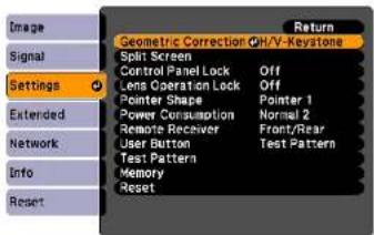

Select "Arc Correction" and prses the Enter button.
Press the Enter button again, and the screen below appears, to select one of the 8 vertical/horizontal areas and corners.
![[Arc Correction] Select the area,](/content/2026/05/815375/images/e09ff31777fa553f466a036fa0a126821d8b92f02a5961ae1195589f81cabf9a.jpg)

Use the [◇] button on the remote control or the [□/▲], [□/▼], [□/◄], and [□/►] buttons on the control panel to select the area you want to adjust, and then press the Enter button.
![[Arc Correction] Select the area.](/content/2026/05/815375/images/4df979fcedcefb62e49d444c2c6e98a00b61bdb3fd45a671deba9b33e4aace91.jpg)
When selecting a corner, you can adjust the two sides next to the corner.

To adjust the shape, use the [◇] button on the remote control or the [▽/▲], [▽/▼], [□/▲], and [□/▶] buttons on the control panel.
Adjusting the Projected Image

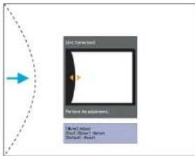
If the triangle in the direction you are adjusting the shape turns gray, as shown in the screenshot below, you cannot adjust the shape any further in that direction.
![[Arc Correction] Cannot adjust any further.](/content/2026/05/815375/images/9f5b9b85049b7205386747ca61463242a4b112e706e58d61d69e0fbdf8743263.jpg)

If you press the [Default] button while adjusting, the value that you are adjusting is reset to the default.

Press the Esc button to return to the previous screen.

Repeat procedures from 3 to 5 as needed to adjust any remaining parts.

When you are done, press the Esc button to exit the correction menu.

If the Esc button is held down for about two seconds while correcting with Arc Correction, the following screen is displayed.
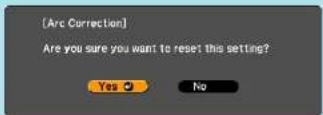
Select "Yes" to reset the result of Arc Correction.
Adjusting the Image Quality

Hue, Saturation, and Brightness Adjustment
The Hue, Saturation, and Brightness for each of the R (red), G (green), B (blue), C (cyan), M (magenta) and Y (yellow) color components can be adjusted.
The menu is displayed in the following order. Image menu - Advanced - RGBCMY
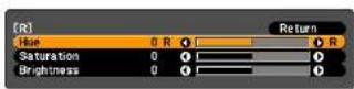
| Hue | Adjusts the overall hue of the image, bluish – greenish – reddish. |
| Saturation Adjusts | the overall vividness of the image. |
| Brightness Adjusts | the overall color brightness of the image. |

If you press the [Default] button while adjusting, the value that you are adjusting is reset to the default.
Gamma Adjustment
Adjust the coloring that is occurred depending on the equipment during displaying the image.
There are three methods of setting as below, which can be selected in the configuration menu.
| Setting Method Menu Settings | |
| Select and adjust the correction value | Image - Advanced - Gamma |
| Setting Method Menu Settings | |
| Adjust while viewing the image | Image - Advanced - Gamma - Customized - Adjust it from the image |
| Adjust using the gamma adjustment graph | Image - Advanced - Gamma - Customized - Adjust it from the graph |
Select and adjust the correction value
![[Gamma] 1-2 0 1-1 10 11 12 1Customized 1Reset Return](/content/2026/05/815375/images/0ed0d183e2d5d6e8db2be3f302256ba71bf0926015c273e0cc8b4b8089e4a493.jpg)
When a smaller value is selected, the dark areas of images become brighter, but the lighter areas may become oversaturated. When a larger value is selected, you can reduce the overall brightness of the image to make the image sharper.

The gamma graph's horizontal axis represents the input signal level and its vertical axis represents the output signal level.
When Color Mode is set to DICOM SIM from the Image menu, select the correction value according to your screen size, referring the size of a 150 inch screen.
If your screen is smaller than 150 inch, select a large value. If your screen is larger than 150 inch, select a small value.

Medical images may not be reproduced correctly according to your settings and screen specifications.
Adjusting the Image Quality

Adjust while viewing the image
Move the cursor on the projected image to the part where you want to change the brightness, and adjust the value.
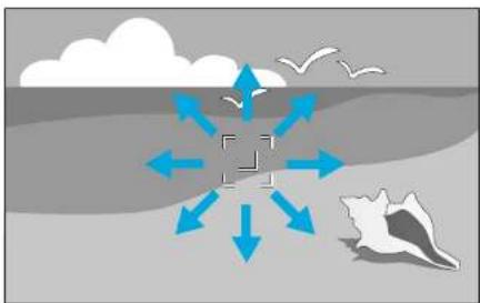
natural_image
Diagram showing directional arrows and a central square object over water with birds flying nearby (no text or symbols)![[Gamma] Color Tone 0 : 0](/content/2026/05/815375/images/a78390b201ded7ec179beb563c986ba5d048d6d475bfb18707aadc4d5f62559f.jpg)

If you press the [Default] button while adjusting, the value that you are adjusting is reset to the default.
Adjust using the gamma adjustment graph
Adjust while looking at the gamma adjustment graph.
![[Gamma] Blinking area is the adjustment target.](/content/2026/05/815375/images/1860156ed955fbab7cff4c55bddbdb4a650fe0abd0ab088ad3ef3b03d081fc2e.jpg)

If you press the [Default] button while adjusting, the value that you are adjusting is reset to the default.
Frame Interpolation (EB-Z8455WU/Z8450WU only)
The current and previous frames are used to create intermediate frames, interpolating to produce smooth-moving images. You can resolve clumsy-moving images, such as frame skipping when projecting a fast moving image.
The menu is displayed in the following order.
Adjusting the Image Quality

Signal Menu - Frame Interpolation
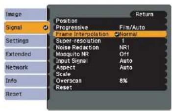
You can select the level of interpolation: Low, Normal or High. Set to Off if noise occurs after setting them.
Super-resolution
To display a crisp image, you can reduce the blurring that is created on the edge when the image data is scaled up to fit the panel resolution of the image signal.
The menu is displayed in the following order. Signal Menu - Super-resolution
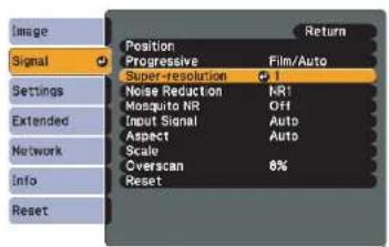
Depending on the image, distortion at the edge of the image may be enhanced. If you notice any distortion, set it to "0".

If you press the [Default] button while adjusting, the value that you are adjusting is reset to the default.
Noise Reduction
There are two kinds of noise reduction functions:
- Noise Reduction
- Mosquito NR
Noise Reduction
You can make settings related to Noise Reduction (reduce flickering of images).
The menu is displayed in the following order. Signal Menu - Noise Reduction
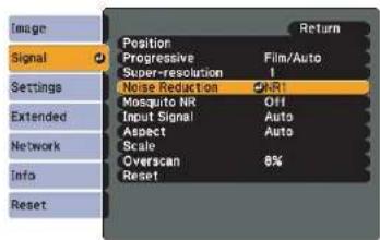
It is recommended that this is set to Off when viewing image sources in which noise is very low, such as for DVDs.
Adjusting the Image Quality

Mosquito NR
You can reduce the wavy noise that occurs in lines between areas with dramatic changes in colors.
The menu is displayed in the following order. Signal Menu - Mosquito NR
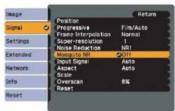
Settings for Multiple Projectors

When projecting to a wide screen from multiple projectors, you can adjust the difference of brightness and color tone between each projected image to create a seamless screen.
There are two general methods of projecting from multiple projectors.
A Projecting different images from each projector, and creating a seamless screen
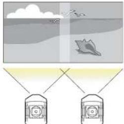
natural_image
Diagram showing two containers connected to a ship under a cloudy sky (no text or symbols)- Projecting the same image from each projector, using the Scale function to project a large image
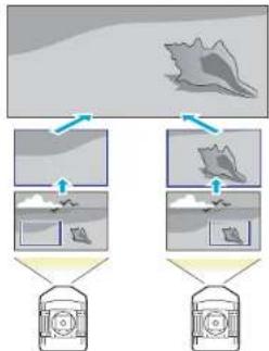
flowchart
graph TD
    A["Image"] --> B["Step 1"]
    B --> C["Device Icon"]
    B --> D["Step 2"]
    D --> E["Device Icon"]
    style A fill:#f9f,stroke:#333
    style B fill:#ccf,stroke:#333
    style C fill:#cfc,stroke:#333
    style D fill:#fcc,stroke:#333
    style E fill:#ffc,stroke:#333
Preparation Flow
Here is an example of using Ⓐ. (The basic flow is the same with Ⓑ method, but use the scale function to adjust the position of the projected image p.157)
- Setting the projector ID and the remote control ID
- Adjusting the position of the projected image
- Checking the Color Mode
- Using the edge blending function
- Adjusting to match colors
Settings are explained here using the remote control, but they can also be set by the control panel.
Projector ID/Remote Control ID
When an ID is set for the projector and the remote control, you can use the remote control to operate only the projector with a matching ID. This is very useful when managing multiple projectors.
When operating all of the projectors from the remote control, set the ID switch on the side of the remote control to Off.

• Operation using the remote control is possible only for projectors that are within the operating range of the remote control.
"Operating range of remote control" p.18
- When Remote Control Type is set to Simple from Operation in the configuration menu, you cannot set the remote control ID.
p.57
- IDs are ignored when the projector ID is set to Off or the remote control ID is set to 0.
Settings for Multiple Projectors

151
Setting the projector ID
Procedure

During projection, press the [Menu] button and select Extended - "Multi-Projection" from the configuration menu. "Using the Configuration Menu" p.47
Remote Control
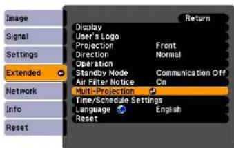

Select "Projector ID", and then press the Enter button.

Select of one of the numbers from 1 to 9 to use as the ID and then press the Enter button.
![[Projector ID] Off 11 12 13 14 15 16 17 18 19](/content/2026/05/815375/images/a9102f913c5cdbba1984d73b863c95e47e06bd6e61581f7ef1f190f162183502.jpg)

Press the [Menu] button to close the configuration menu.
Checking the Projector ID
Use the following procedure to check the projector ID.
Procedure

Set the remote control ID switch to On.
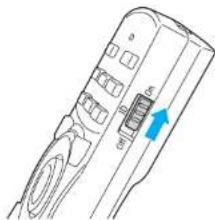
natural_image
Line drawing of a remote control device with a blue arrow pointing to the left side (no text or symbols present)Settings for Multiple Projectors

152

During projection, while holding the [ID] button, press the [Help] button.
Remote Control
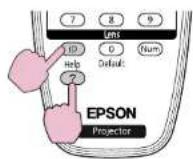
When you press the buttons, the current Projector ID is displayed on the projection screen. It disappears in about three seconds.
Setting the remote control ID
Procedure

Set the remote control ID switch to On.
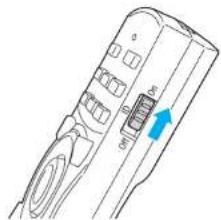
natural_image
Line drawing of a handheld device with a blue arrow pointing to a button (no text or symbols)
While holding the [ID] button, press a number button to select a number to match the ID of the projector you want to operate. "Checking the Projector ID" p.151
Remote Control
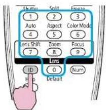
Once this setting has been made, the projector that can be operated by the remote control is limited.

The remote control ID setting is saved in the remote control. Even if the remote control batteries are removed to replace them and so on, the stored ID setting is retained. However, if the batteries are left out for a long time, it is reset to the default value (ID0).
Adjusting the Position of the Projected Image
Adjust the position of the projected image, starting from the adjustments that have larger corrections.
-
Projector's position (angle) p.130
-
Lens shift/Zoom p.138
-
Geometric Correction
• Quick Corner p.140
- Point Correction p.153
Settings for Multiple Projectors


- We recommend setting the focus, zoom, and lens shift at least 30 minutes after you start the projection, because images are not stable right after turning on the projector.
- The Test Pattern can be displayed to adjust the projection status without connecting video equipment. p.137
- When projecting from multiple projectors, the correction is easier if you use the image in dot by dot format, that can be displayed without being enlarged or reduced.
Point Correction
Corrects slight distortion which occurs partially, or adjusts the screen position in an overlapping area when projecting from multiple projectors. Divides the projected image by the grid and corrects the distortion by moving the point of intersection from side to side and up and down.
Procedure

During projection, press the [Menu] button. Select Settings menu - "Geometric Correction" and then press the Enter button. "Using the Configuration Menu" p.47
Remote Control
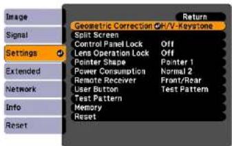

Select "Point Correction", and then press the Enter button.

Select "Grid Size", and then press the Enter button.

Select one of "3x3", "5x5", or "9x9", and then press the Enter button.

Press the Esc button to return to the previous screen.

Select "Start Adjustments", and then press the Enter button.
According to the value selected in Grid Size, the point selection screen is displayed on the projected image.

You can change the color of the guide on Pattern Color.
Settings for Multiple Projectors

154

Move the [☐] button to the point you want to correct, then press the Enter button.
Remote Control
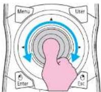
![[Point Correction] H-Pos: 4 V-Pos: 4 [●]:Select [Esc]:Return [Enter]:Enter](/content/2026/05/815375/images/eafcd34ed6f9fb2ab60d0c2d6514d32c83524cb890f77e7f9ca93d286a0e2e28.jpg)

If the Esc button is held down for about two seconds while selecting the point, the confirm default reset screen is displayed. Select "Yes" to reset the result of Point Correction.

Press the [◎] button to correct the distortion. Remote Control
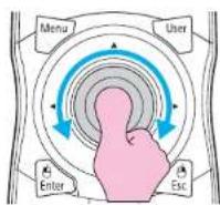
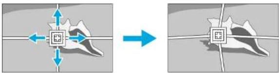
natural_image
Diagram showing a hand holding a small object with directional arrows, before and after a transformation (no text or symbols)To continue to correct another point, press the |Esc| button to return to the previous screen, then repeat the step 7 and 8.

If you press the [Default] button while adjusting, the value that you are adjusting is reset to the default.

When you are done, press the Esc button to exit the correction menu.
Checking the Color Mode
Set the Color Mode to Multi-Projection p.28
Using the Edge Blending Function
When multiple projectors are lined up and projecting images, you can create a seamless screen.
Make the following settings on the Edge Blending menu, to correct the image.
| Sub Menu Function | |
| Edge Blending | Set to On to activate the edge blending function. Set to Off when not projecting from multiple projectors. |
| Top Edge/Bottom Edge/Right Edge/Left Edge | Blending: Set to On to activate the edge blending function towards where you are setting, and the brend range will be shaded.Blend Range: Adjusts the range to be shaded. Adjustment is possible at the level of one pixel. The maximum range is 45% of resolution. |
| Blend Curve You can select from three ways of shading. | |
| Black Level When projecting a dark image, correct the part that is not overlapped to resolve the brightness of overlapped part.Brightness Correct.: Adjust the brightness of the range that is not shaded.Color Correct. (G/R): Adjust the color tone of the range that is not shaded to greenish and reddish.Color Correct. (B/Y): Adjust the color tone of the range that is not shaded to bluish and yellowish. | |
| Guide Display | Set to On to display the guide on the edge blending setting range. |
| Guide Colors You can select the combination of guide colors from the three. | |
Procedure

Press the [Menu] button and select Extended menu - "Multi-Projection" from the configuration menu "Using the Configuration Menu" p.47
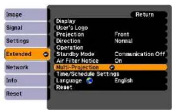

Select "Edge Blending", and then press the Enter button.

Turn on "Edge Blending".
(1) Select Edge Blending, and then press the Enter button.
(2) Select On, and then press the Enter button.
(3) Press the Esc button.

Displays the guide.
(1) Select the Guide Display, and then press the Enter button.
(2) Select On, and then press the Enter button.
(3) Press the Esc button.

If the guide is not clear, you can change the color of the guide on Guide Colors.

Set "Top Edge/Bottom Edge/Right Edge/Left Edge".
(1) Select Top Edge/Bottom Edge/Right Edge/Left Edge to set the edge blending, and then press the Enter button.
(2) Select Blending, and then press the Enter button.
(3) Select On, and then press the Enter button.
(4) Press the Esc button.
(5) In Blend Range, adjust the range to be shaded.
The value for when the overlapped range and the guide are in the same position is the best.
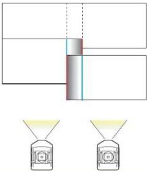
natural_image
Diagram showing two identical funnel-shaped objects with yellow liquid, connected by a central vertical bar and dashed lines (no text or symbols)
If you press the [Default] button while adjusting Blend Range, the value that you are adjusting is reset to the default.
(6) Press the Esc button.

Set "Blend Curve".
(1) Select Blend Curve, and then press the Enter button.
(2) Select the way of shading from 1 to 3, and then press the Enter button.
(3) Press the Esc button.

Adjust the black level.
(1) Select Black Level, and then press the Enter button.
(2) In Brightness Correct., adjust the level to correct.
(3) In Color Correct. (G/R), adjust the level to correct.
(4) In Color Correct. (B/Y), adjust the level to correct.
(5) Press the Esc button.

If you press the [Default] button while adjusting Brightness Correct, Color Correct. (G/R), or Color Correct. (B/Y), the item that you are selecting is reset to the default.
Adjusting to Match Colors on Multi-Projection
When multiple projectors are lined up and projecting images, you can manually correct the brightness and color tone of each projector's image so that the colors projected from each projector match closely.
In some cases the brightness and color tone may not match completely even after correction.
Make the following settings on the Multi-Projection menu to correct the image.
| Sub Menu Function | |
| Brightness Level Adjust when the brightness of each projector is different. | |
| Multi-screen | Adjustment Level: Change the adjustment level of the projected image.Brightness Correct.: Adjust from black to white for each color tone.Color Correct. (G/R): Adjust the color tone to greenish and reddish.Color Correct. (B/Y): Adjust the color tone to bluish and yellowish. |

If the overlapping part of dark images is annoying, adjust the Black Level again.
Displays the Image Partly Enlarged (Scale)
Procedure

During projection, press the [Menu] button. Select Signal menu - "Scale" and then press the Enter button. "Using the Configuration Menu" p.47
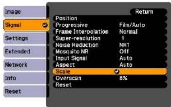

Select "Scale", and then select "On".

Select "Scale Mode", and then select the scale.
Full Display When the image is not resized, it is projected the same as projected by Normal aspect mode.
Settings for Multiple Projectors

Zoom Display The image is displayed at the range that is selected on the aspect mode. p.22

Select "Scale Vertically", "Scale Horizontally", or "scale vertically and horizontally at the same time", and then adjust the scale.

Set "Image Display Range".
Adjust the scale while watching the screen, because clipping coordinates position and clipping size are different according to screens to be matched, such as matching top and bottom screens or left and right screens.
Setting Schedule

You can schedule turning the projector power on/off and switching the input source, as events in the schedule. Registered events are executed automatically at the specified time on the specified dates or weekly.
Setting Methods
You can make settings from the computer by using the Web Remote function. p.109
Procedure

Press the [Menu] button, and select Extended - "Time/Schedule Settings" from the configuration menu "Using the Configuration Menu" p.47
Using the Remote Control Using the Control Panel
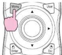
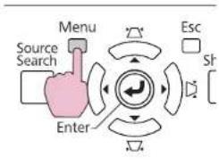
flowchart
graph TD
    A["Source Search"] --> B["Menu"]
    B --> C["Enter"]
    C --> D["Esc"]
    D --> E["Sl"]
    E --> F["Output"]
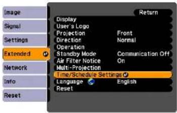

Set the time and schedule.
Selecting from the top menu and sub menus, and changing of selected items are the same as operations in the configuration menu.
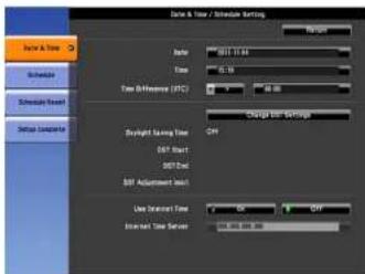
To delete all registered schedules, select Schedule Reset, then select Yes.

Select the Setup complete menu, and then select "Yes". You can return to the configuration menu.
Clock
| Sub Menu Function | |
| Date | Set today's date in the projector. |
| Time | Set the current time in the projector. |
| Time Difference (UTC) | Set the time difference from Coordinated Universal Time. |
| Change DST Settings | Displays the screen to set the daylight saving time. |
| Use Internet Time | Set to On to update the time automatically through an Internet time server. |
| Sub Menu Function | |
| Internet Time Server | Input the IP address for an Internet time server. |
Daylight Saving Time screen
| Sub Menu Function | |
| Daylight Saving Time | Set whether or not (On/Off) to activate the daylight saving time. |
| DST Start | Set the date and time to start the daylight saving time. |
| DST End | Set the date and time to end the daylight saving time. |
| DST Adjustment (min) | Adjusts the time difference between the standard time and the daylight saving time. |
Schedule
You can display the list of registered schedules.
When you select Edit on a registered schedule or New Event, the Clock / Schedule Setting screen is displayed.
You can register up to 30 events.
Clock / Schedule Setting screen
| Sub Menu Function | |
| Event Settings | Select an operation of the projector when the event is executed. |
| Date / Time Settings | Set the date and time to execute the event. |
Connecting a LAN Cable
Connect with a commercially available 100BASE-TX or 10BASE-T LAN cable.
| Connected equipment | Connecting cable Projector port | |
| LAN port on network hub | LAN cable (commercially available) | LAN port --- --- |
Attention
To prevent malfunctions, use a category 5 shielded LAN cable.
Connecting to an External Monitor
You can display computer images input from a computer on an external monitor connected to the projector and the screen at the same time. This means that you can check projected images on an external monitor when giving presentations even if you cannot see the screen. Connect using the cable supplied with the external monitor.
| Connected equipment | Connecting cable Projector port |
| Monitor Cable supplied with monitor Monitor Out port |  |

- Only analog RGB signals from a computer connected to the Computer input port or the BNC input port can be displayed on an external monitor. Images from equipment connected to other ports and component video signals cannot be displayed.
- The image cannot be displayed on the external monitor when the projector is on standby.
- Setting gauges such as Keystone, the configuration menu, or Help screens are not output to the external monitor.
Installing Optional and Supplied Accessories

Prepare #2 plus-driver in advance.
Removing and Attaching the Projector Lens Unit
Removing
Attention
- Only remove the lens unit when necessary. If dust or dirt enter the projector, projection quality deteriorates and it could cause a malfunction.
- Try not to touch the lens section with your hand or fingers. If fingerprints or oils are left on the surface of the lens, projection quality deteriorates.
- If the lens shift has been done, set the lens shift to the center before replacing the lens unit. p.138
Procedure

Remove the interface cover.
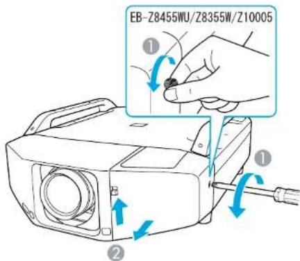
① Loosen the fixing screw.
② While pulling up the interface cover open switch, pull the interface cover straight out.

Remove the front cover.
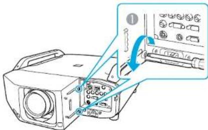
Installing Optional and Supplied Accessories

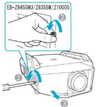
① Loosen the two fixing screws.
② Loosen the fixing screw.
③ Pull the cover straight out.

Pinch the lock lever of the lens unit and turn it counterclockwise.
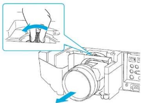
natural_image
Diagram of a mechanical device with a hand operating a component, showing a blue arrow indicating rotation (no text or symbols present)
Pull the lens unit straight out as it is released.
Attaching
Attention
Do not attach the lens unit when the projector's lens insertion section is facing up. Dust or dirt could enter the projector.
Procedure

Insert the lens unit straight into the lens insertion section with the white circle on the lens on top.
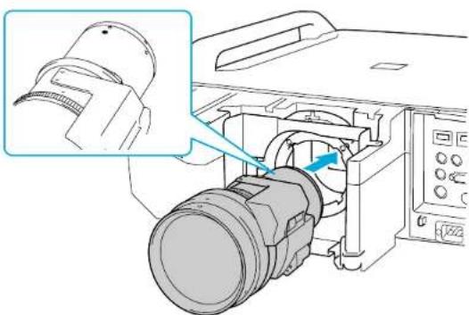
natural_image
Technical diagram of a mechanical assembly with a magnified inset showing a component detail (no text or symbols visible)
Replace the front cover.
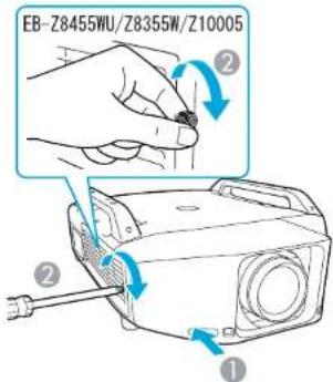

While holding the lens unit firmly, turn the lock lever clockwise until it is locked. Check that the lens cannot be detached.
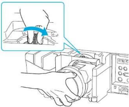
natural_image
Illustration of hands operating a mechanical device with a magnified inset showing the component being adjusted (no text or symbols present)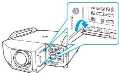
1 Install the cover along the guide.
② Tighten the fixing screw.
③ Tighten the two fixing screws.

Replace the interface cover.
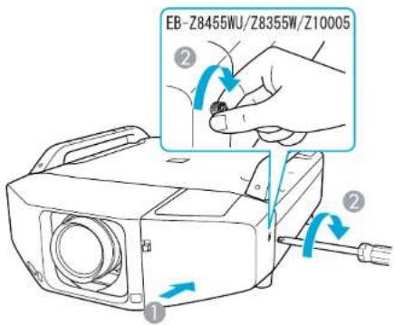
① Install the cover along the guide.
② Tighten the fixing screw.
Attention
• Install the front cover to use the projector.
- Store the projector with the lens unit installed.
If the projector is stored without the lens unit, dust and dirt may get inside the projector and cause malfunctions or lower the quality of projection.
Installing the Wireless LAN Unit (ELPAP07)
Attaching
Procedure

Remove the interface cover.
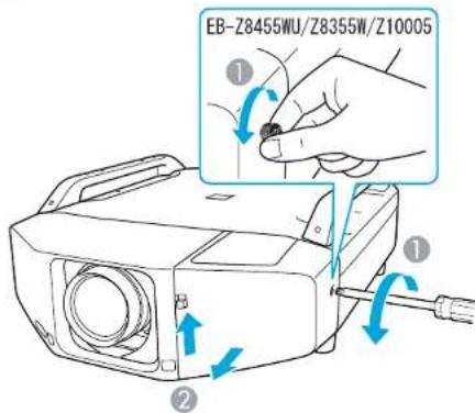
1 Loosen the fixing screw.
② While pulling up the interface cover open switch, pull the interface cover straight out.

Install the Wireless LAN unit.
Installing Optional and Supplied Accessories

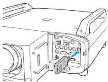
natural_image
Line drawing of an electronic device rear panel with ports and connectors (no text or symbols)When connecting a projector to which the Wireless LAN unit is mounted to a computer using a wireless LAN, set the Wireless LAN Power setting on the Wireless LAN menu to On. (The default setting is On.)
p.63
Reading the wireless LAN indicators
There are two wireless LAN indicators, one on the projector and one on the Wireless LAN unit.
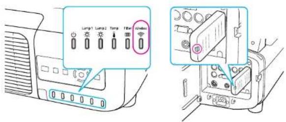

Flashing
Lit:Off
| Status Indicator on projector | Indicator on Wireless LAN unit | |
| The Wireless LAN unit not mounted or the Wireless LAN Power setting on the Wireless LAN menu is Off | ||
| The Wireless LAN unit mounted to the projector but not connected to the network | (HKY8) | (X320) |
| The Wireless LAN unit mounted to the projector and connected to the network | ||
| The Wireless LAN unit mounted to the projector, connected to the network, and communicating | (BYZ7) | |
Attaching and Removing the Interface Cover
Removing
Procedure

Loosen the fixing screw.
Installing Optional and Supplied Accessories

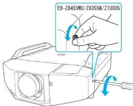
2 While pulling up the interface cover open switch, pull the interface cover straight out.
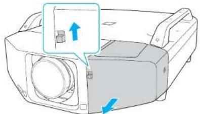
natural_image
Diagram of a printer or printer with a magnified inset showing a component, no text or symbols present.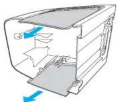
natural_image
Diagram of a computer case with blue arrows indicating directional flow (no text or symbols)② Install the cover along the guide.
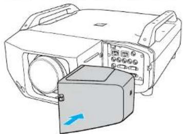
natural_image
Technical line drawing of a mechanical device with a blue arrow indicating a component (no text or symbols present)③ Tighten the fixing screw.
Attaching
Procedure
1 Remove the top cover when ejecting the connected cables upward. Remove the bottom cover when ejecting the connected cables downward.
Installing Optional and Supplied Accessories

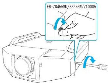
Removing the Feet
When mounting the projector on the ceiling, you can remove the feet and attach the supplied foot covers for clean appearance.
Procedure

Remove the feet.
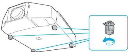
natural_image
Technical line drawing of a mechanical component with a magnified inset showing a rotating component (no text or symbols)
Attach the supplied foot covers.
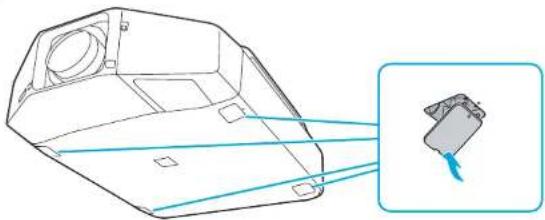
natural_image
Technical line drawing of a mechanical component with a magnified inset showing internal components (no text or symbols)
Appendix
Optional Accessories and Consumables

The following optional accessories and consumables are available. Please purchase these products as and when needed. The following list of optional accessories and consumables is current as of: 2012.1. Details of accessories are subject to change without notice and availability may vary depending on the country of purchase.
Optional Accessories
| Computer cable ELPKC02(1.8 m - for mini D-Sub15-pin/mini D-Sub 15pin)This is the same as the computer cable supplied with the projector. |
| Computer cable ELPKC09(3 m - for mini D-Sub15-pin/mini D-Sub 15pin)Computer cable ELPKC10(20 m - for mini D-Sub15-pin/mini D-Sub 15pin)Use one of these longer cables if the computer cable supplied with the projector is too short. |
| Component video cable ELPKC19(3 m - for mini D-Sub 15-pin/RCA made)Use to connect a Component Video source. |
| Remote control cable set ELPKC28(10m 2 piece set)Use this to guarantee operation from the remote control from a distance. |
| Wireless mouse receiver ELPST16Use this to use the projector's remote control to control the mouse pointer on the computer or to page up and down. |
| Wireless LAN unit ELPAP07Use this to project images from a computer via a wireless LAN. |
Low ceiling mount* ELPMB25
High ceiling mount* ELPMB26
Use when installing the projector on a ceiling.
* A special method of installation is required to suspend the projector from a ceiling. Contact your dealer or the nearest address provided in the Support and Service Guide if you want to use this installation method. Epson Projector Contact List
Consumables
| Replacement lamp unit (two-pack) ELPLP73Replacement lamp unit (one-pack) ELPLP72Use as a replacement for used lamps. |
| Air filter ELPAF23Use as a replacement for used air filters. |
Screen Size and Projection Distance

The following table shows the projection distance when a standard lens is attached. When an optional lens is attached, check the projection distances using the ELPLL07/ELPLM07/ELPLM06/ELPLS04/ELPLW04/ELPLR04 User's Guide supplied with this projector. To find the appropriate screen size, see the following table to set up the projector. Values are just reference.
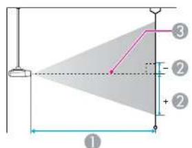
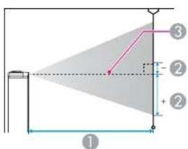
1 Projection distance
② is the distance from the center of the lens to the base of the screen. This changes depending on the setting for vertical lens shift.
3 Center of lens
Projection Distance of EB-Z8455WU/Z8450WU
Units: cm
| 4:3Screen Size | 1 | 2 | |
| Minimum (Wide) to Maximum(Tele) | Vertical lens shiftTop to Bottom | ||
| 53" 108x8 | 1 221 - 361 -17 | - +98 | |
| 70" 142x1 | 07 294 - 479 -23 | - +129 | |
| 80" 163x1 | 22 338 - 549 -26 | - +148 | |
| 90" 183x1 | 37 381 - 619 -29 | - +166 | |
| 100" 203x | 152 424 - 688 -32 | - +185 | |
| 4:3Screen Size | 1 | 2 | |
| Minimum (Wide) to Maximum(Tele) | Vertical lens shiftTop to Bottom | ||
| 110" 224x | 168 467 - 758 - | 35 - +203 | |
| 120" 244x | 183 510 - 828 - | 39 - +221 | |
| 150" 305x | 229 640 - 1036 | 48 - +277 | |
| 200" 406x | 305 856 - 1384 | -64 - +369 | |
| 300" 610x | 457 1288 - 2081 | -97 - +554 | |
| 441" 896x | 672 1898 - 3062 | -142 - +814 | |
Units: cm
| 16:9Screen Size | 1 | 2 | |
| Minimum (Wide) to Maximum(Tele) | Vertical lens shiftTop to Bottom | ||
| 59" 131x7 | 3 223 - 365 -21 | - +95 | |
| 70" 155x8 | 7 267 - 434 -25 | - +112 | |
| 80" 177x1 | 100 306 - 498 -29 | - +129 | |
| 90" 199x1 | 12 345 - 561 -33 | - +145 | |
| 100" 221x | 125 384 - 624 -36 | - +161 | |
| 110" 244x | 137 423 - 687 -40 | - +177 | |
| 120" 266x | 149 463 - 751 -43 | - +193 | |
| 150" 332x | 187 580 - 940 -54 | - +241 | |
| 200" 443x | 249 777 - 1256 -72 | - +321 | |
| 300" 664x | 374 1169 - 1888 | -108 - +482 | |
| 486" | 1076x605 | 1899 - 3064 | -176 - +781 |
Units: cm
| 16:10Screen Size | 1 | 2 | |
| Minimum (Wide) to Maximum(Tele) | Vertical lens shiftTop to Bottom | ||
| 60" 130x8 | 1 221 - 361 -17 | - +98 | |
| 70" 151x9 | 4 259 - 423 -20 | - +114 | |
| 80" 172x1 | 08 297 - 484 -23 | - +130 | |
| 90" 194x1 | 21 335 - 546 -26 | - +147 | |
| 100" 215x | 135 374 - 607 -28 | - +163 | |
| 110" 237x | 148 412 - 669 -31 | - +179 | |
| 120" 258x | 162 450 - 730 -34 | - +196 | |
| 200" 431x | 269 755 - 1222 | -57 - +326 | |
| 300" 646x | 404 1137 - 1837 | -85 - +489 | |
| 500" 1077x | 673 | 1900 - 3067 | -142 - +815 |
Projection Distance of EB-Z8355W/Z8350W
Units: cm
| 4:3Screen Size | 1 | 2 | |
| Minimum (Wide) to Maximum(Tele) | Vertical lens shiftTop to Bottom | ||
| 53" 108x8 | 1 217 - 355 -16 | +97 | |
| 70" 142x1 | 07 290 - 472 -2 | - +128 | |
| 80" 163x1 | 22 332 - 540 -24 | - +146 | |
| 90" 183x1 | 37 375 - 609 -27 | - +165 | |
| 100" 203x | 152 417 - 677 -30 | - +183 | |
| 110" 224x | 168 460 - 746 -34 | - +201 | |
| 4:3Screen Size | 1 | 2 | |
| Minimum (Wide) to Maximum(Tele) | Vertical lens shiftTop to Bottom | ||
| 120" 244x | 183 502 - 814 - 37 - +219 | ||
| 150" 305x | 229 630 - 1020 | 46 - +274 | |
| 200" 406x | 305 843 - 1363 | 61 - +366 | |
| 300" 610x | 457 1268 - 2048 | -91 - +549 | |
| 441" 896x | 672 1868 - 3014 | -134 - +807 | |
Units: cm
| 16:9Screen Size | 1 | 2 | |
| Minimum (Wide) to Maximum(Tele) | Vertical lens shiftTop to Bottom | ||
| 59" 131x7 | 3 220 - 359 -20 | +94 | |
| 70" 155x8 | 7 262 - 428 -24 | - +111 | |
| 80" 177x1 | 100 301 - 490 -28 | - +127 | |
| 90" 199x1 | 12 339 - 552 -31 | - +143 | |
| 100" 221x | 125 378 - 614 -35 | - +159 | |
| 110" 244x | 137 417 - 676 -38 | - +175 | |
| 120" 266x | 149 455 - 739 -42 | - +191 | |
| 150" 332x | 187 571 - 925 -52 | - +239 | |
| 200" 443x | 249 764 - 1236 | -69 - +318 | |
| 300" 664x | 374 1150 - 1859 | -104 - +477 | |
| 486" 1076x | 605 | 1869 - 3016 | -168 - +773 |
Units: cm
| 16:10Screen Size | 1 | 2 | |
| Minimum (Wide) to Maximum(Tele) | Vertical lens shiftTop to Bottom | ||
| 60" 130x8 | 1 217 - 355 -16 | - +97 | |
| 70" 151x9 | 4 255 - 416 -19 | - +113 | |
| 80" 172x1 | 08 292 - 476 -22 | - +129 | |
| 90" 194x1 | 21 330 - 537 -24 | - +145 | |
| 100" 215x | 135 368 - 597 -27 | - +162 | |
| 110" 237x | 148 405 - 658 -30 | - +178 | |
| 120" 258x | 162 443 - 719 -32 | - +194 | |
| 200" 431x | 269 743 - 1203 | -54 - +323 | |
| 300" 646x | 404 1119 - 1808 | -81 - +485 | |
| 500" 1077 | x673 | 1870 - 3019 | -135 - +808 |
Projection Distance of EB-Z10005/Z10000/Z8150
Units: cm
| 4:3Screen Size | 1 | 2 | |
| Minimum (Wide) to Maximum(Tele) | Vertical lens shiftTop to Bottom | ||
| 60" 122x9 | 1 194 - 319 | -5 - +97 | |
| 70" 142x1 | 07 228 - 373 -6 | - +113 | |
| 80" 163x1 | 22 261 - 428 -7 | - +129 | |
| 90" 183x1 | 37 295 - 482 -8 | - +145 | |
| 100" 203x | 152 329 - 537 -8 | - +161 | |
| 110" 224x | 168 362 - 591 -9 | - +177 | |
| 4:3Screen Size | 1 | 2 | |
| Minimum (Wide) to Maximum(Tele) | Vertical lens shiftTop to Bottom | ||
| 120" 244x | 183 396 - 646 - | 10 - +193 | |
| 200" 406x | 305 665 - 1082 | -17 - +322 | |
| 300" 610x | 457 1002 - 1626 | -25 - +483 | |
| 500" 1016x | 762 | 1676 - 2716 -42 - +804 | |
Units: cm
| 16:9Screen Size | 1 | 2 | |
| Minimum (Wide) to Maximum(Tele) | Vertical lens shiftTop to Bottom | ||
| 56" 124x7 | 0 197 - 324 -17 | - +87 | |
| 70" 155x8 | 7 249 - 407 -21 | - +108 | |
| 80" 177x1 | 00 285 - 467 -24 | - +124 | |
| 90" 199x1 | 12 322 - 526 -27 | - +139 | |
| 100" 221x | 125 359 - 586 -30 | - +155 | |
| 110" 244x | 137 395 - 645 -33 | - +170 | |
| 120" 266x | 149 432 - 704 -36 | - +185 | |
| 150" 332x | 187 542 - 882 -45 | - +232 | |
| 200" 443x | 249 726 - 1179 | 60 - +309 | |
| 300" 664x | 374 1093 - 1773 | -90 - +464 | |
| 458" 1014x | 570 | 1672 - 2711 | -137 - +708 |
Units: cm
| 16:10Screen Size | 1 | 2 | |
| Minimum (Wide) to Maximum(Tele) | Vertical lens shiftTop to Bottom | ||
| 57" 123x7 | 195 - 321 -13 | - +90 | |
| 70" 151x9 | 242 - 396 -16 | - +110 | |
| 80" 172x1 | 08 277 - 454 -18 | - +126 | |
| 90" 194x1 | 21 313 - 512 -20 | - +141 | |
| 100" 215x | 135 349 - 569 -22 | - +157 | |
| 110" 237x | 148 385 - 627 -25 | - +173 | |
| 120" 258x | 162 420 - 685 -27 | - +188 | |
| 150" 323x | 202 527 - 858 -34 | - +236 | |
| 200" 431x | 269 706 - 1147 | 45 - +314 | |
| 300" 646x | 404 1063 - 1725 | -67 - +471 | |
| 471" 1014 | x634 | 1673 - 2712 | -106 - +740 |
Supported Monitor Displays
Computer signals (analog RGB)
| Signal Refresh Rate (Hz) Resolution (dots) | ||
| VGA 60/72/75/85 640x480 | ||
| SVGA 56/60/72/75/85 800x600 | ||
| XGA 60/70/75/85 1024x768 | ||
| WXGA 60 1280x768 | ||
| 60 1366x768 | ||
| 60/75/85 1280x800 | ||
| WXGA+ 60/75/85 1440x900 | ||
| WSXGA+*1 | 60 1680x1050 | |
| WXGA++ | 60 | 1600x900 TBD |
| SXGA | 70/75/85 1152x864 | |
| 60/75/85 | 1280x1024 | |
| 60/75/85 1280x960 | ||
| SXGA+ | 60/75 | 1400x1050 |
| UXGA | 60 1600x1200 | |
| WUXGA*2 | 60 1920x1200 | |
*1 EB-Z8455WU/Z8450WU/Z8355W/Z8350W only. Only compatible when Wide is selected as the Resolution from the configuration menu.
*2 EB-Z8455WU/Z8450WU only. Only compatible when VESA CVT-RB (Reduced Blanking) signal is input.
Even when signals other than those mentioned above are input, it is likely that the image can be projected. However, not all functions may be supported.
Component Video
| Signal Refresh Rate (Hz) | Resolution (dots) | |
| SDTV(480i) | 60 | 720x480 |
| SDTV(576i) | 50 | 720x576 |
| SDTV(480p) | 60 | 720x480 |
| SDTV(576p) | 50 | 720x576 |
| HDTV(720p) | 50/60 | 1280x720 |
| HDTV(1080i) | 50/60 | 1920x1080 |
| HDTV(1080p)^* | 50/60 | 1920x1080 |
* EB-Z8455WU/Z8450WU only
Composite Video/S-Video
| Signal | Refresh Rate (Hz) | Resolution (dots) |
| TV(NTSC) | 60 | 720x480 |
| TV(PAL,SECAM) | 50/60 | 720x576 |
Input signals from HDMI1/2 input port
| Signal Refresh | Rate (Hz) | Resolution (dots) |
| VGA | 60 | 640x480 |
| SVGA | 60 | 800x600 |
| XGA | 60 1024x768 | |
| WXGA 60 1280x800 | ||
| SXGA | 60 1280x960 | |
| 60 1280x1024 | ||
| SXGA+ | 60 1400x1050 | |
| WXGA++ | 60 | 1600x900 TBD |
| Signal Refresh Rate (Hz) Resolution (dots) | ||
| WXGA 60 1366x768 TBD | ||
| WXGA+ 60 1440x900 TBD | ||
| UXGA 60 1600x1200 | ||
| WSXGA+*1 | 60 1680x1050 | |
| WUXGA*2 | 60 1920x1200 | |
| SDTV(480i) 60 720x480 | ||
| SDTV(480p) 60 720x480 | ||
| SDTV(576i) 50 720x576 | ||
| SDTV(576p) 50 720x576 | ||
| HDTV(720p) 50/60 1280x720 | ||
| HDTV(1080i) 50/60 | 1920x1080 | |
| HDTV(1080p) | 24/30/50/60 | 1920x1080 |
*1 EB-Z8455WU/Z8450WU/Z8355W/Z8350W only. Only compatible when Wide is selected as the Resolution from the configuration menu.
*2 Only compatible when VESA CVT-RB (Reduced Blanking) signal is input.
Input signals from SDI input port (EB-Z8455WU/Z8450WU only)
| Signal | Refresh Rate (Hz) | Resolution (dots) |
| SDTV(480i) 60 720x480 | ||
| SDTV(576i) 50 720x576 | ||
| HDTV(720p) 50/60 1280x720 | ||
| HDTV(1080i) 50/60 | 1920x1080 | |
| 11DTV(1080p) | 24/30 | 1920x1080 |
Supported Certificates

Client Certificate (PEAP-TLS/EAP-TLS)
| Item Explanation | |
| Supported format PKCS#12 | |
| Extension PKCS, P12 | |
| Encryption RSA | |
| Hashes MD5/SHA-1/SHA | 256/SHA -384/SHA -512 |
| Key length 512/1024/2048/4096 bit | |
| Password Required (up to 32 alphanumeric characters) | |
Server Certificate (PEAP/PEAP-TLS/EAP-TLS/EAP-Fast)
| Item Explanation | |
| Supported format X509v3 | |
| Extension DER/CER/PEM | |
| Encryption RSA | |
| Hashes MD5/SHA-1/SHA-256/SHA-384/SHA-512 | |
| Key length 512/1024/2048/4096 bit | |
| Encode BASE64/Binary | |
Web Server Certificate (Secure HTTP)
| Item Explanation | |
| Supported format PKCS#12 | |
| Extension PKCS, P12 | |
| Encryption RSA | |
| Hashes MD5/SIIA-1/SIIA-256/SIIA-384/SIIA-512 | |
| Key length 512/1024/2048/4096 bit | |
| Item Explanation | |
| Common Name Network | host name |
| Organization Optional | |
| Password Required (up to 32 alphanumeric characters) | |
Projector General Specifications
| Product name | EB-Z8455WU/Z8450WU EB | Z8355W/Z8350W EB-Z10005/Z | 0000 EB-Z8150 | ||
| Dimensions | 534 (W) × 167 (H) × 734 (D) mm (not including raised section) | ||||
| Panel size | 0.94" Wide 0.95" Wide 1.06" | ||||
| Display method | Polysilicon TFT active matrix | ||||
| Resolution | 2,304,000 pixelsWUXGA (1920 (W) × 1200 (H) dots) × 3 | 1,024,000 pixelsWXGA (1280 (W) × 800 (H) dots) × 3 | 786,432 pixelsXGA (1024 (W) × 768 (H) dots) × 3 | ||
| Focus adjustment | Automatic | ||||
| Zoom adjustment*1 | Automatic (1-1.6) | ||||
| Lens shift*1 | Automatic (Vertical direction: Maximum approx. 70%, Horizontal direction: Maximum approx. 20%) | Automatic (Vertical direction: Maximum approx. 56%, Horizontal direction: Maximum approx. 6%) | |||
| Lamp | UHE lamp, 340 W Two-lamps Model No.: ELPLP73 (Two)/ELPLP72 (One) | ||||
| Power supply | 100-240V AC ±10%, 50/60 Hz 9.8-4.3A 100-240V AC ±10%, Hz 8.3-3.5A | 50/60Hz | |||
| Power consumption | 100 to 120 V area | Operating: 968WStandby power consumption (Communication On): 4.3WStandby power consumption (Communication Off): 0.4W | Operating: 822WStandby power consumption (Communication On): 4.3WStandby power consumption (Communication Off): 0.4W | ||
| 220 to 240 V area | Operating: 911WStandby power consumption (Communication On): 5.1WStandby power consumption (Communication Off): 0.5W | Operating: 786WStandby power consumption (Communication On): 5.1WStandby power consumption (Communication Off): 0.5W | |||
| Operating altitude | Altitude 0 to 3048 m | ||||
| Operating temperature | 0 to +50°C2 (No condensation) | ||||
| Storage temperature | -10 to +60°C (No condensation) | ||||
| Mass*1 | Approx. 22 kg | ||||
*1 The specifications are when a standard lens is attached. When an optional lens is attached, check the User's Guide supplied with the optional lenses.
*2 The operating temperature is 0 to +50°C when Power Consumption is set to Normal 2, and 0 to +45°C when it is set to Normal 1 at an altitude of 0 to 1500m. The operating temperature is 0 to +45°C when Power Consumption is set to Normal 2, and 0 to +40°C when it is set to Normal 1 at an altitude of 1500 to 3048m.
| Product name | EB-Z8455WU/Z8450WU | EB-Z8355W/Z8350W EB-Z100 | 05/Z10000 EB-Z8150 | |||
| Connec-tors | Computer Input Port 1 | Mini D-Sub15-pin (female) blue | ||||
| BNC input port 1 | 5BNC (female) | |||||
| Video input port 1 | 1BNC (female) | |||||
| S-Video input port 1 | Mini DIN 4-pin | |||||
| HDMI1 input port | 1 | HDMI HDCP compatible | ||||
| HDMI2 input port | 1 | HDMI HDCP compatible | ||||
| SDI input port | 1 | 1BNC (female) | - | |||
| Monitor Out port | 1 | Mini D-Sub15-pin (female) black | ||||
| USB port(Only for Wireless LAN unit)* | 1 | USB connector (Type A) | ||||
| LAN port | 1 | RJ-45 | ||||
| RS-232C port | 1 | Mini D-Sub 9-pin (male) | ||||
| Remote port | 1 | Stereo mini jack | ||||
* USB 2.0 is supported. However, the operation of all USB compatible devices is not guaranteed.
Specifications

This product is also designed for IT power distribution system with phase-to-phase voltage 230V.
Angle of tilt
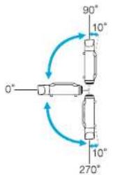
Using the projector at angles not shown in the illustrations above may damage it or cause an accident.
DECLARATION of CONFORMITY
According to 47CFR, Part 2 and 15
Class B Personal Computers and Peripherals; and/or
CPU Boards and Power Supplies used with Class B
Personal Computers
We: Epson America, Inc.
Located at: 3840 Kilroy Airport Way
MS: 3-13
Long Beach, CA 90806
Tel: 562-290-5254
Declare under sole responsibility that the product identified herein, complies with 47CFR Part 2 and 15 of the FCC rules as a Class B digital device. Each product marketed, is identical to the representative unit tested and found to be compliant with the standards. Records maintained continue to reflect the equipment being produced can be expected to be within the variation accepted, due to quantity production and testing on a statistical basis as required by 47CFR 2.909. Operation is subject to the following two conditions: (1) this device may not cause harmful interference, and (2) this device must accept any interference received, including interference that may cause undesired operation.
Trade Name: EPSON
Type of Product: LCD Projector
Model: H458C/H459C/H460C/H462C
FCC Compliance Statement
For United States Users
This equipment has been tested and found to comply with the limits for a Class B digital device, pursuant to Part 15 of the FCC Rules. These limits are designed to provide reasonable protection against harmful interference in a residential installation. This equipment generates, uses, and can radiate radio frequency energy and, if not installed and used in accordance with the instructions, may cause harmful interference to radio communications. However, there is no guarantee that interference will not occur in a particular installation. If this equipment does cause harmful interference to radio or television reception, which can be determined by turning the equipment off and on, the user is encouraged to try to correct the interference by one or more of the following measures.
• Reorient or relocate the receiving antenna.
- Increase the separation between the equipment and receiver.
- Connect the equipment into an outlet on a circuit different from that to which the receiver is connected.
- Consult the dealer or an experienced radio/TV technician for help.
WARNING
The connection of a non-shielded equipment interface cable to this equipment will invalidate the FCC Certification or Declaration of this device and may cause interference levels which exceed the limits established by the FCC for this equipment. It is the responsibility of the user to obtain and use a shielded equipment interface cable with this device. If this equipment has more than one interface connector, do not leave cables connected to unused interfaces. Changes or modifications not expressly approved by the manufacturer could void the user's authority to operate the equipment.
Appearance

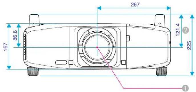
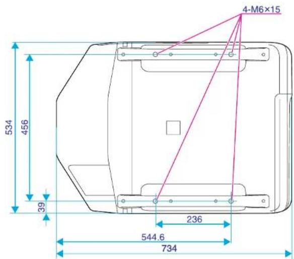
Units: mm
① Center of lens
② Distance from center of lens to suspension bracket fixing point
Glossary

This section explains easily terms that are used with the projector and difficult terms that are not explained in the text of this guide. For details, refer to other commercially available publications.
| Ad hoc mode | A method of wireless LAN connection that communicates with wireless LAN clients without using an access point. |
| AMX Device Discovery | AMX Device Discovery is a technology developed by AMX to facilitate AMX control systems for easy operation of the target equipment.Epson have implemented this protocol technology, and have provided a setting to enable the protocol function (ON).See the AMX Web site for more details.URL http://www.amx.com/ |
| Aspect Ratio(Aspect Ratio) | The ratio between an image's length and its height. HIDTV images have an aspect ratio of 16:9 and appear elongated. The aspect ratio for standard images is 4:3. |
| Component Video | A Video signal which has the luminance component and color component separated to provide better image quality.Refers to images that consist of three independent signals: Y (luminance signal), Pb and Pr (color difference signals). |
| Composite video | Video signals that have the video brightness signals and color signals mixed together. The type of signals commonly used by household video equipment (NTSC, PAL, and SECAM formats). The carrier signal Y (luminance signal) and chroma (color) signal that are contained in the color bar are overlapped to form a single signal. |
| Contrast | The relative brightness of the light and dark areas of an image can be increased or decreased to make text and graphics stand out more clearly, or to make them appear softer. Adjusting this particular property of an image is called Contrast adjustment. |
| DHCP | An abbreviation of Dynamic Host Configuration Protocol, this protocol automatically assigns an IP Address to equipment connected to a Network. |
| DICOM | An acronym for Digital Imaging and Communications in Medicine. An international standard that defines image standards and a communications protocol for medical images. |
| Gateway address(Gateway Address) | This is a server (router) for communicating across a network (subnet) divided according to subnet masks . |
| HDCP | HDCP is an abbreviation for High-bandwidth Digital Content Protection. It is used to prevent illegal copying and protect copyrights by encrypting digital signals sent over DVI and HDMI input ports. Digital images protected by HDCP technology can be projected with this projector because the projector's HDMI input ports are compatible with HDCP. However, the projector may not be able to project images protected with updated or revised versions of HDCP encryption. |
| HDTV | An abbreviation for High-Definition Television that refers to high-definition systems which satisfy the following conditions.Vertical resolution of 720p or 1080i or greater (p Progressive , i = Interlace )Screen Aspect Ratio of 16:9 |
| Infrastructure mode | A method for wireless LAN connection in which devices communicate through access points. |
| Interlace | A method of image scanning whereby the image data is divided into fine horizontal lines that are displayed in sequence starting from left to right and then from top to bottom. The even-numbered lines and odd-numbered lines are displayed alternately. |
| IP Address | A number to identify a computer connected to a Network. |
| Progressive | A method of image scanning whereby the image data from a single image is scanned sequentially from top to bottom to create a single image. |
| Refresh Rate | The light-emitting element of a display maintains the same luminosity and color for an extremely short time. Because of this, the image must be scanned many times per second to refresh the light-emitting element. The number of refresh operations per second is called the Refresh Rate and is expressed in hertz (Hz). |
| SDI | An abbreviation for Serial Digital Interface. The projector is compatible with both SD-SDI (Standard Definition) and IID-SDI (High Definition) methods. |
| SDTV | An abbreviation for Standard Definition Television that refers to standard television systems which do not satisfy the conditions for HDTV High-Definition Television. |
| SNMP | An abbreviation for Simple Network Management Protocol, which is the protocol for monitoring and controlling devices such as routers and computers connected to a TCP/IP Network. |
| sRGB | An international standard for color intervals that was formulated so that colors that are reproduced by video equipment can be handled easily by computer operating systems (OS) and the Internet. If the connected source has an sRGB mode, set both the projector and the connected signal source to sRGB. |
| Subnet mask(Subnet Mask) | This is a numerical value that defines the number of bits used for the network address on a divided network (subnet) from the IP Address . |
| SVGA | A type of video signal with a resolution of 800 (horizontal) × 600 (vertical) dots that is used by IBM PC/AT-compatible computers. |
| S-Video | A Video signal which has the luminance component and color component separated to provide better image quality.Refers to images that consist of two independent signals: Y (luminance signal) and C (color signal). |
| SXGA | A type of video signal with a resolution of 1,280 (horizontal) × 1,024 (vertical) dots that is used by IBM PC/AT-compatible computers. |
| Sync. | The signals output from computers have a specific frequency. If the projector frequency does not match this frequency, the resulting images are not of a good quality. The process of matching the phases of these signals (the relative position of the crests and the troughs in the signal) is called Synchronization. If the signals are not synchronized, flickering, blurriness, and horizontal interference occur. |
| Tracking | The signals output from computers have a specific frequency. If the projector frequency does not match this frequency, the resulting images are not of a good quality. The process of matching the frequency of these signals (the number of crests in the signal) is called Tracking. If Tracking is not carried out correctly, wide vertical stripes appear in the signal. |
| Trap IP Address | This is the IP Address for the destination computer used for error notification in SNMP. |
| VGA | A type of video signal with a resolution of 640 (horizontal) × 480 (vertical) dots that is used by IBM PC/AT-compatible computers. |
| WPS (Wi-Fi Protected Setup) | Wi-Fi Protected Setup has been devised by the Wi-Fi Alliance as a means of easily setting up and securing a wireless LAN. |
| XGA | A type of video signal with a resolution of 1,024 (horizontal) × 768 (vertical) dots that is used by IBM PC/AT-compatible computers. |
General Notes

All rights reserved. No part of this publication may be reproduced, stored in a retrieval system, or transmitted in any form or by any means, electronic, mechanical, photocopying, recording, or otherwise, without the prior written permission of Seiko Epson Corporation. No patent liability is assumed with respect to the use of the information contained herein. Neither is any liability assumed for damages resulting from the use of the information contained herein.
Neither Seiko Epson Corporation nor its affiliates shall be liable to the purchaser of this product or third parties for damages, losses, costs, or expenses incurred by the purchaser or third parties as a result of: accident, misuse, or abuse of this product or unauthorized modifications, repairs, or alterations to this product, or (excluding the U.S.) failure to strictly comply with Seiko Epson Corporation's operating and maintenance instructions.
Seiko Epson Corporation shall not be liable against any damages or problems arising from the use of any options or any consumable products other than those designated as Original Epson Products or Epson Approved Products by Seiko Epson Corporation.
The contents of this guide may be changed or updated without further notice.
Illustrations in this guide and the actual projector may differ.
About Notations
Microsoft® Windows® 2000 operating system
Microsoft® Windows® XP Professional operating system
Microsoft® Windows® XP Home Edition operating system
Microsoft® Windows Vista® operating system
Microsoft® Windows® 7 operating system
In this guide, the operating systems above are referred to as "Windows 2000," "Windows XP," "Windows Vista," and "Windows 7". Furthermore, the collective term Windows may be used to refer to Windows 2000, Windows XP, Windows Vista, and Windows 7, and multiple versions of Windows may be referred to as, for example, Windows 2000/XP/Vista, with the Windows notation omitted.
Mac OS X 10.3.x
Mac OS X 10.4.x
Mac OS X 10.5.x
Mac OS X 10.6.x
Mac OS X 10.7.x
In this guide, the operating systems above are referred to as "Mac OS X 10.3.9," "Mac OS X 10.4.x," "Mac OS X 10.5.x," "Mac OS X 10.6.x" and "Mac OS X 10.7.x". Furthermore, the collective term "Mac OS" is used to refer to them.
General Notice
Microsoft, Windows, Windows NT, Windows Vista, Windows 7, PowerPoint, and Windows logo are trademarks or registered trademarks of Microsoft Corporation in the United States and/or other countries.
IBM, DOS/V, and XGA are trademarks or registered trademarks of International Business Machines Corp.
Macintosh and Mac are registered trademarks of Apple Inc.
Pixelworks and DNX are trademarks of Pixelworks Inc.
This product includes RSA BSAFE™ software from RSA Security Inc. RSA is a registered trademark of RSA Security Inc. BSAFE RSA Security Inc. is a registered trade mark in the United States and other countries.
WPA ^™ , WPA2 ^™ and Wi-Fi Protected Setup ^™ are registered trademarks of Wi-Fi Alliance.
PJLink trademark is a trademark applied for registration or is already registered in Japan, the United States of America and other countries and areas.
HDMI and High-Definition Multimedia Interface are the trademarks or registered trademarks of HDMI Licensing LLC. HDMI
Other product names used herein are also for identification purposes only and may be trademarks of their respective owners. Epson disclaims any and all rights in those marks.
General Notes

186
©SEIKO EPSON CORPORATION 2012. All rights reserved.
Index

♦ indicator 83
A
Abs. Color Temp. 51
Administrator Password 71
Administrator Settings Menu 71
Advanced 52
Air Filter Notice 58
Air filter replacement period 104
Air intake vent 11
AMX Device Discovery 71
Angle of tilt 180
Arc Correction 55
Aspect 22,54
Auto Setup 53
B
Basic Menu 62
Beep 58
BNC input port 13
BNC Sync Termination 58
Bonjour 72
Brightness 51
Brightness Level 58
C
CA certificate 74
Cable cover 166
Ceiling mount fixing points 11
Certificates 111, 177
Cleaning the Air Filter 98
Cleaning the Projector's Surface 98
Client Certificate 74
Color Mode 28,51
Color Saturation 51
Computer input port 13
Configuration Menu 47
Connect to a Network Projector .... 124
Consumables 170
Contrast 51
Control Panel 14
Control Panel Lock 40, 41, 55
Crestron RoomView 72, 118
Cross 35
D
DHCP 70
DICOM SIM 28
Direct Power On 58
Direction 57
Display 57
Display Background 57
Distance 171
Dynamic 28
E
EasyMP Monitor 108
Front adjustable foot 11
Front cover 11,162
Full 22
G
Gateway Address 64,70
Geometric Correction 55
H
H/V-Keystone 55,142
Handle 11
HDMI Video Range 54
HDMI1 input port 13
HDMI2 input port 13
High Altitude Mode 58
How to replace the air filter 104
How to replace the lamp 101
I
Image Menu 51
Indicators 83
Info Menu 77
Input Signal 54,77
Installation and Connections 129
Interface cover 11, 162, 165
IP Address 70
Index

K
Keystone 142
L
Lamp cover 12
Lamp Hours 77
Lamp replacement period 101
Lamp Status 77
Lamp1/2 indicator 83
Language 59
Lens 14
Lens Control 110
Lens Operation Lock 41, 55
Lens shift 138
Lens Shift button 16
Load Memory 56
M
Mail Notification 73,113
Mail Notification menu 73
Manage Certificates menu 74
Memory 56
Menu Position 57
Message Broadcasting 122
Messages 57
Monitor Out port 13
Monitor Password 71
Mosquito NR 54, 149
Operating temperature 178
Operation 58
Optional accessories 170
Overheating 84
Overscan 54
P
Part Names and Functions .... 11
Password Protect 38,60
Password protect sticker 39
Photo 28
PJLink 117
PJLink Password 71
Point Correction 55
Pointer 34
Pointer Shape 55
Port Number 73
Position 53
Power Consumption 55
Power inlet 13
Power On Protect 38
Presentation 28
Priority Gateway 71
Problem Solving 83
Progressive 53
Projection 57
Projection distance 171
Projection lens 11, 162
Projector ID 58,151
Projector Keyword 62
Projector Name 62
Q
Quick Corner 55,139
R
Rear screen 130
Refresh Rate 77
Remote Control 15
Remote control button lock 42
Remote control ID 152
Remote port 13
Remote Receiver 11
Rename Memory 56
Request Code 40
Reset All 79
Reset Memory 79
Reset Menu 76,79
Resetting the lamp operating time ..... 103
Resolution 77,175
RS-232C port 13,115
s
Save Memory 56
Scale 54
Index

Schedule 159
Screen Size 31
SDI port 13
SDI Video Range 54
Search Access Point 65
Secure HTTP 71
Security Menu 66
Security slot 11
Self-signed Certificate 74
Setting a Notification Event 73
Settings Menu 55
Sharpness 51
Shutter 14,33
Shutter Timer 58
Signal Menu 53
Sleep Mode 58
SMTP Server 73
SNMP menu 75
Soft Kyeboard 61
Source 30,77
Source Search 14,20
Specifications 178
Split Screen 55
Split Screen Setup 30
Sports 28
sRGB 28
Standby Mode 58
Startup Screen 57
Storage temperature 178
Subnet Mask 70
Super-resolution 53
Supported Monitor Displays 175
S-Video Input Port 13
Swap Screens 30
Sync Info 77
Sync. 53
T
Temp indicator 83
Test Pattern 56,137
Theatre 28
Time/Schedule Settings 59
Tint 51
Tracking 53
Trap IP Address 1/2 75
U
User's Logo 36
User's Logo Protect 38
V
Video input port 13
Video Signal 54,77
W
Web Control 60,109
Web Control Password 71
Web Remote 109
Web Remote Password 62
Web Server Certificate 74
Wired LAN Menu 70
Wireless LAN indicator 166
Wireless LAN Menu 63
Wireless LAN Power 63
Wireless LAN unit 165
WPA/WPA2-EAP 68
WPA/WPA2-PSK 67
Z
Zoom 16,22

- Notations Used in This Guide
- - Safety indications
- - General information indications
- • Screen shots of the configuration menu
- Contents
- Notations Used in This Guide 2
- Introduction
- Projector Features ....Selecting the Projection Quality (Selecting Color Mode) .... 28
- Part Names and Functions .... Restrictions during Split Screen Projection....
- Selecting the Projection Quality (Selecting Color Mode) ..... 28
- Projecting Two Images Simultaneously (Split Screen) ..... 29
- Functions for Enhancing Projection 33
- Saving a User's Logo 36
- Security Functions 38
- Memory Function 44
- Configuration Menu
- Network Functions
- Monitoring and Controls
- Installation and Connections
- Appendix
- Settings for Multiple Project or s 150
- Optional Accessories and Consumables 170
- Screen Size and Projection Distance 171
- Supported Monitor Displays 17
- Setting Schedule 159
- Supported Certificates 17
- Specifications 178
- Connecting to External Equipment 161
- Appearance 182
- 2.1.1.1.
- General Notes 185
- Installing Optional and Supplied Accessories .... 1
- Index 165 187
- Ease of Use when Installed on a Ceiling Mount
- Centered lens
- Equipped with electric lens shift, zoom and focus functions
- Variety of optional lenses available
- Various angles of projection
- Easy maintenance
- Reliability You can Depend on
- Dual lamps, to reduce risk of shutdown
- Achieves operating temperature of 0–50°C
- Meets a Wide Range of Needs
- Projector Features
- Project two images simultaneously (Split Screen)
- Clearly reproduce medical images
- Epson Cinema Filter supports the color gamut for digital cinema.
- Precise color adjustments
- Seamlessly project multiple images together
- Enhanced Security Functions
- Password Protect to restrict and manage users
- Control Panel Lock restricts button operation on the control panel
- Equipped with various anti-theft devices
- Easy to Handle
- No cool down delay
- Monitoring and Control Functions
- Schedule
- Supporting various protocols
- Taking Full Advantage of a Network Connection
- Simultaneously project four images for dynamic conferences
- Project using "Connect to a Network Projector"
- Front/Top
- Caution
- Interface
- Installing the batteries
- Attention
- Procedure
- Remove the battery cover.
- Insert the batteries in the correct direction.
- Replace the battery cover.
- Operating range of remote control
- Useful Functions
- Changing the Projected Image
- Automatically Detect Input Signal and Change the Projected Image (Source Search)
- Switch to the Target Image by Remote Control
- Changing the Aspect Ratio of the Projected Image
- Changing the Aspect Mode (EB-Z8455WU/Z8450WU)
- Projecting images from video equipment or from the HDMI1/2 or SDI input port
- Projecting images from a computer
- Changing the Aspect Mode (EB-Z8355W/Z8350W)
- Projecting images from video equipment or from the HDMI1/2 input port
- Changing the Aspect Mode (EB-Z10005/Z10000/Z8150)
- Projecting images from video equipment
- Projecting images from the HDMI1/2 input port
- Selecting the Projection Quality (Selecting Color Mode)
- Projecting Two Images Simultaneously (Split Screen)
- Input Sources for Split Screen Projection
- Operating Procedures
- Switching the left and right screens
- Restrictions during Split Screen Projection
- Operating restrictions
- Restriction relating to images
- Hiding the Image Temporarily (Shutter)
- Freezing the Image (Freeze)
- Functions for Enhancing Projection
- Pointer Function (Pointer)
- Enlarging Part of the Image (E-Zoom)
- Saving a User's Logo
- Security Functions
- Managing Users (Password Protect)
- Type of Password Protect
- Power On Protect
- User's Logo Protect
- Network Protect
- Setting Password Protect
- Turn on "Power On Protect".
- Turn on "User's Logo Protect".
- Turn on "Network Protect".
- Set the Password.
- Entering the Password
- Control Panel Lock
- Restricting Button Operation
- Lens Operation Lock
- Remote control button lock
- Anti-Theft Lock
- Installing the wire lock
- Memory Function
- Available Settings
- Saving/Loading/Erasing the Memory
- Saving the memory
- Loading the memory
- Erasing the memory
- Renaming the memory
- Using the Configuration Menu
- Image Menu
- Signal Menu
- Network Menu
- Notes on Operating the Network Menu
- Soft Keyboard Operations
- Basic Menu
- Wireless LAN Menu
- Search Access Point screen
- Security Menu (Only Available when the Optional Wireless LAN Unit Is Installed)
- When WPA/WPA2-EAP is selected
- Wired LAN Menu
- Administrator Settings Menu
- Mail Notification menu
- Manage Certificates menu
- SNMP menu
- Reset Menu
- Info Menu (Display Only)
- Troubleshooting
- Using the Help
- Problem Solving
- Reading the Indicators
- Indicator is lit or flashing red
- Indicator is flashing or lit
- When the Indicators Provide No Help
- Problems relating to images
- Problems when projection starts
- Other problems
- Interpreting Event IDs
- Maintenance
- Cleaning
- Warning
- Cleaning the Projector's Surface
- Cleaning the Lens
- Cleaning the Air Filter
- Replace the air filter cover.
- Replacing the Lamps
- Lamp replacement period
- How to replace the lamp
- Replacing Consumables
- Install the new lamp.
- Resetting the Lamp Hours
- Replace the lamp cover.
- Replacing the Air Filter
- Air filter replacement period
- How to replace the air filter
- Notes on Transportation
- Notes when packing and transporting
- Moving Nearby
- When Transporting
- Preparing packaging
- EasyMP Monitor
- Changing Settings Using a Web Browser (Web Control)
- Displaying Web Control
- Displaying Web Remote
- Displaying Lens Control
- Setting Certificates
- Secure HTTP Notes
- Using the Mail Notification Function to Report Problems
- Reading Problem Mail Notification Function
- Management Using SNMP
- Serial Connection
- Communications Protocol
- Command List
- About PJLink
- About Crestron RoomView®
- a Operating a Projector from a Computer Window
- Displaying the operation window
- Using the operation window
- Using the tools window
- ③ Admin Password
- User Password
- About Message Broadcasting
- Projecting with "Connect to a Network Projector"
- Making a WPS (Wi-Fi Protected Setup) Connection with a Wireless LAN Access Point
- Connection Setup Method
- Making a connection using the push button method
- Making a connection using the PIN Code Method
- Installation Methods
- Connecting to Video Equipment
- Connecting to a Computer
- Changing the video output from a laptop computer.
- Displaying a Test Pattern
- Adjusting the Projected Image
- Adjusting the Position of the Projected Image (Lens Shift)
- Adjusting the Tilt of the Projected Image
- Correcting Distortion in the Projected Image
- Quick Corner
- H/V-Keystone
- Arc Correction
- Adjusting the Image Quality
- Hue, Saturation, and Brightness Adjustment
- Gamma Adjustment
- Adjust while viewing the image
- Adjust using the gamma adjustment graph
- Frame Interpolation (EB-Z8455WU/Z8450WU only)
- Super-resolution
- Noise Reduction
- Mosquito NR
- Settings for Multiple Projectors
- Preparation Flow
- Projector ID/Remote Control ID
- Setting the remote control ID
- Adjusting the Position of the Projected Image
- Point Correction
- Checking the Color Mode
- Using the Edge Blending Function
- Displays the guide.
- Set "Top Edge/Bottom Edge/Right Edge/Left Edge".
- Set "Blend Curve".
- Adjust the black level.
- Adjusting to Match Colors on Multi-Projection
- Displays the Image Partly Enlarged (Scale)
- Setting Schedule
- Setting Methods
- Connecting a LAN Cable
- Connecting to an External Monitor
- Installing Optional and Supplied Accessories
- Removing and Attaching the Projector Lens Unit
- Removing
- Attaching
- Installing the Wireless LAN Unit (ELPAP07)
- Reading the wireless LAN indicators
- Attaching and Removing the Interface Cover
- Removing the Feet
- Optional Accessories and Consumables
- Screen Size and Projection Distance
- Supported Monitor Displays
- Supported Certificates
- Specifications
- DECLARATION of CONFORMITY
- FCC Compliance Statement
- For United States Users
- Appearance
- Glossary
- General Notes
- About Notations
- General Notice
- Index
- A
- B
- C
- D
- E
- G
- H
- I
- K
- L
- M
- P
- Q
- R
- s
- T
- U
- V
- W
- Z
Brand : EPSON
Model : EB-Z10005U
Category : Video projector