
Thesis TH quattro - Receiver AUDISON - Free user manual and instructions
Find the device manual for free Thesis TH quattro AUDISON in PDF.


| Product Type | Receiver (Car Audio Power Amplifier) |
| Brand | Audison |
| Model | Thesis TH quattro |
| Number of Channels | 4 (configurable as 4, 3, or 2 channels) |
| Output Power (Hi-Current Mode, 4 Ch @ 4 Ω) | 160 W RMS per channel |
| Output Power (Class A Mode, 4 Ch @ 4 Ω) | 55 W RMS per channel |
| Frequency Response | 5 Hz - 70 kHz (-3 dB) |
| Signal-to-Noise Ratio | 104 dBA (1 V, max power) |
| THD (1 kHz, 4 Ω, 90% power) | < 0.03% |
| Input Sensitivity (Analog) | 0.3 - 1.2 V (Hi) / 1.2 - 4.8 V (Lo) |
| Input Impedance (Pre IN) | Not specified (typical ~10 kΩ) |
| Load Impedance (Hi-Current Mode) | Min 2 Ω (4 Ch), 1 Ω (2 Ch) |
| Load Impedance (Class A Mode) | Min 4 Ω |
| Power Supply Voltage | 11 - 15 VDC |
| Idling Current (Hi-AB Class) | 6.6 A |
| Fuse Rating | 100 A (AFS type) |
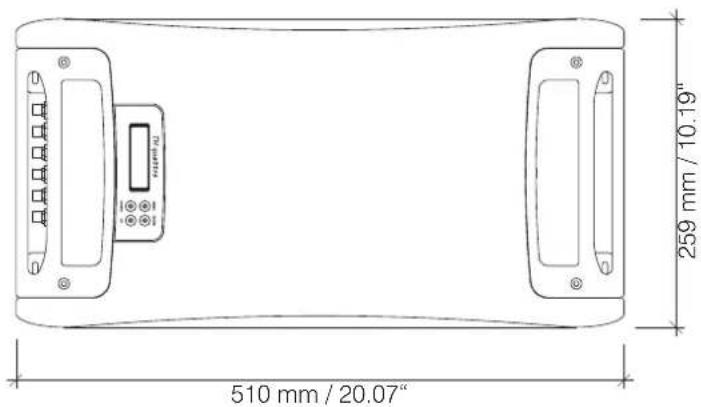
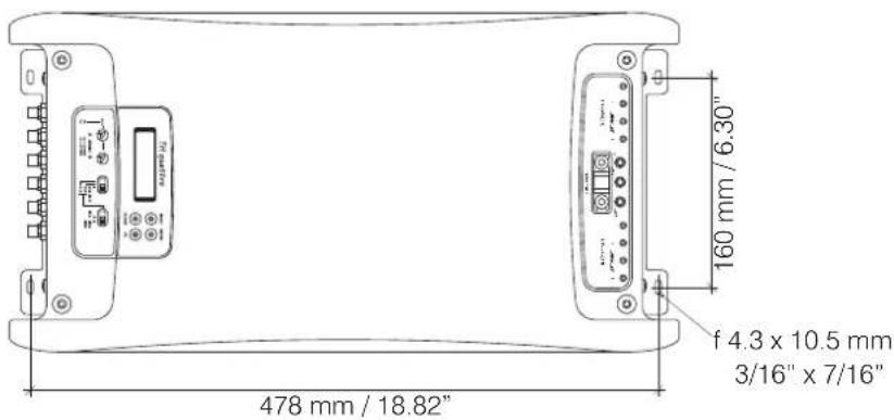
| Dimensions (W x L x H) | 259 x 510 x 67 mm (10.2 x 20.1 x 2.6 in) |
| Weight | 10.3 kg (22.7 lbs) |
| Digital Input | Optical (S/PDIF, up to 192 kHz / 24 bit) and AD Link (RJ-45) |
| Analog Inputs / Outputs | Stereo RCA IN A & IN B, Pre-out bypass (OUT A) |
| Crossover | Removable modules, Hi-pass/Lo-pass/Band-pass, 12 or 24 dB/oct, 32 frequencies |
| Control Network | AC Link (RJ-12), USB interface, ACNet PC software |
| Remote Control | DRC (Digital Remote Control, optional) - Volume, Source, Balance, Fader, Sub Volume |
| Dual Power Modes | Class A, Hi-AB Class, Hi-Current, Energy Saving |
| Included Accessories | Crossover kit (modules + boards), cables (AC Link, AD Link, USB), fuse, CD, manual |
Frequently Asked Questions - Thesis TH quattro AUDISON
User questions about Thesis TH quattro AUDISON
0 question about this device. Answer the ones you know or ask your own.
Ask a new question about this device
Download the instructions for your Receiver in PDF format for free! Find your manual Thesis TH quattro - AUDISON and take your electronic device back in hand. On this page are published all the documents necessary for the use of your device. Thesis TH quattro by AUDISON.
USER MANUAL Thesis TH quattro AUDISON
THESIS - The project 4
Packaging Contents 5
Installation 6
Fixing template 7
Rear Panel 11
Functions Description 11
How to remove the panel / the protection knob 11
How to connect the power supply 12
How to replace the fuse 13
How to connect the speakers in 4 Ch mode 14
How to connect the speakers in 3 Ch mode 15
How to connect the speakers in 2 Ch mode 16
Input controls 17
Functions Description 17
How to move from one sensitivity range to another 17
Front Panel 18
Functions Description 18
How to connect the remote 19
How to connect the source through the preamplified analog input (4 Ch mode) 20
How to connect the source through the preamplified analog input (3 Ch mode) 21
How to connect the source through the preamplified analog input (2 Ch mode) 22
Electronic Crossover 23
TH in 4 Ch mode - Filtering A channels and B channels 24
TH in 3 Ch mode - Filtering A channels 24
TH in 3 Ch mode - Filtering B channels (Setup X-Over Slope 12 dB) 25
TH in 2 Ch mode - Filtering A channels and B channels (Setup X-Over Slope 12 dB) 25
TH in 3 Ch mode - Filtering B channels (Setup X-Over Slope 24 dB) 26
How to insert 27
Examples 28
Two Way, multi-amplified, TH amplifier, Analog Input 28
Two Way + Sub, multi-amplified, TH amplifier, Analog Input 29
Three Way + Sub, multi-amplified, TH amplifier, Analog Input 30
Three Way + Sub, multi-amplified, with and without TH amplifiers, Analog Input 31
THESIS 32
ASC (AMPLIFIER STATUS CONTROLLER) 32
INPUTS AND PRE-AMPLIFIER 32
ASC - Amplifier Status Controller 33
Functions Description 33
Setup Amplifier: Main Input 34
Digital Inputs 35
How to adjust the volume control and input selector using a digital source 35
Front Panel 36
How to achieve same output volume level using an analog source
(with its own volume control) and a digital source 36
How to connect a source through the optical digital input
in a system featuring more than one TH amplifier (4 / 3 / 2 Ch mode) 37
How to connect a source through the optical digital input
in a system featuring other non-TH amplifiers (4 / 3 / 2 Ch mode) 38
How to connect an analog and a digital source
in a system featuring more than one amplifier (4 / 3 / 2 Ch mode) 39
How to connect an analog and a digital source
in a system featuring more than one amplifier (4 / 3 / 2 Ch mode) 40
THESIS
INDEX
ASC - Amplifier Status Controller 41
Setup Amplifier: Amp ID on 4 Ch Mode 41
Setup Amplifier: Amp ID on 3 Ch Mode 42
Setup Amplifier: Amp ID on 2 Ch Mode 43
Setup Amplifier: Amp ID-Preout 44
Front Panel 45
How to adjust the PRE OUT analog input 45
ASC - Amplifier Status Controller 46
Setup Amplifier: X-Over Slope of bridged channels (B) with TH in 3 Ch mode 46
Setup Amplifier: X-Over Slope of bridged channels with TH in 2 Ch mode 46
DUAL POWER & BIAS CONTROL 47
Setup Amplifier: DUAL POWER Settings 47
DUAL POWER Values 48
How to change presets on the Memory 49
Examples
50
Three Way + Sub, multi-amplified, TH amplifiers, Digital Input 50
Three Way + Sub, multi-amplified, TH amplifiers, Analog + Digital Input 51
Three Way + Sub, multi-amplified, with and without TH amplifiers, Analog + Digital Input 52
ASC - Amplifier Status Controller 53
Status Monitor 53
Runtime Monitor 54
Info and Alert sentences 55
DRC - Digital Remote Control 56
Info and Alert sentences 57
How to connect 58
How to install 58
ACNet - Audison Control Network 59
Amplifier Setting: Identification 62
Amplifier Setting: Inputs 63
Amplifier Setting: Sensitivity and Preout Level 64
Amplifier Setting: Dual Power Memory 65
System Audio Control 66
Amplifier Status 67
System Amplitude Setup 68
System Dual Power Setup 69
Technical Specifications 70
THESIS
The Project
The roads travelled to reach "the Sound" have created a conceptual cross-road, where state of the art digital technology and traditional techniques have gone their separate ways.
They both have benefits of a different nature, yet are capable of merging together to achieve much higher Sound quality levels.
The Thesis amplifiers are born from these considerations. The parts related to signal amplification are manufactured using the highest level of analog technology while, at the same time, the input section along with the processing and monitoring functions of the amplifier are the result of the most advanced digital technology.
The TH quattro is a four-channel power amplifier, designed for use in car. It is technologically progressive, featuring original circuitry, with extraordinary sound, consistent with Audison tradition.
Sections:
This manual is divided into sections allowing the use of the TH amplifier in standard settings or using its specific features in "digital" settings. Each section is marked by its corresponding bookmark.
General Part:
The TH amplifiers need to be connected like any other amplifier, in compliance with safe working conditions. Installation as well as power supply and speaker connections have to be made properly, following the standard methods a specialty store normally follows.
Classic Domain:
Despite the endless settings and customising possibilities ASC (Amplifier Status Controller) offers, the TH amplifiers can also be used in a traditional way, taking advantage of the analog inputs and of the controls which provide the signal to the final stages.
The setting of the sensitivity, stereo or bridged mono configuration, the inputs sensitivity, the electronic crossovers on slide-through boards as well as the PRE bypass out, anyway let to include the TH within the traditional systems or to build amplifying chains with absolute audiophile quality.
Digital Domain:
The TH amplifiers feature ASC (Amplifier Status Controller) which provides several factory functions for the complete control of all the amplifier's functions.
Heart of the system is a digital power microprocessor. It manages the amplifier functions and communicates with the user through a control panel as well as the Display Monitor, featuring the DRC remote control or, in a more complete and direct way, through the ACNet Audison Controller Network software.
The ASC menu allows the amplifier set up, monitors the working conditions, viewable through a Status Monitor feature, also making the data available on the display intermittently. A USB connector enables the connection of the system to a computer, while the AC Link (Audison Control Link) allows the creation of communication network. The software will take care of the functional operations for all the amplifiers within the whole chain (system), providing a simple and complete interface. A revolutionary method for configuration which, up to know, were impossible to achieve with traditional designs.
Packaging Contents
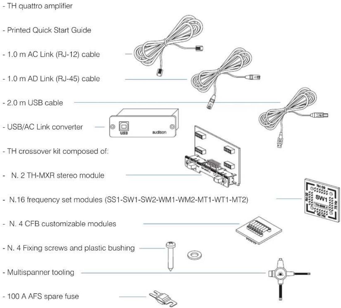
- TH quattro amplifier
- Printed Quick Start Guide
- 1.0 m AC Link (RJ-12) cable
- 1.0 m AD Link (RJ-45) cable
- 2.0 m USB cable
- USB/AC Link converter
- TH crossover kit composed of:
- N. 2 TH-MXR stereo module
- N.16 frequency set modules (SS1-SW1-SW2-WM1-WM2-MT1-WT1-MT2)
- N. 4 CFB customizable modules
- N. 4 Fixing screws and plastic bushing
- Multispanner tooling
- 100 A AFS spare fuse
- INSTALLATION CD with:
CD ROM TEST SIGNALS
ACNet Software Track 01. sine sweep (0 dB) - 10 min
This Advanced Manual (.pdf) Track 02. white noise (-12 dB) - 15 min
AC Link Drivers Track 03. pink noise (0 dB) - 10 min
USB-ACNet Drivers Track 04. sine wave 50 Hz (0 dB) - 2 min
Track_05. sine wave 1 kHz (0 dB) - 2 min
Available accessories (not included):
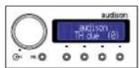
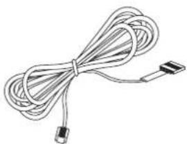
DRC - Digital Remote Control
- DRC control panel
- 4.5 m DRC/AC Link cable
- N.2 fixing brackets
natural_image
Coiled cable with connectors, no text or symbols visible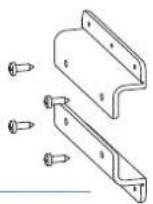
Installation
External size
How to fix
Fixing size
THES
Fixing te
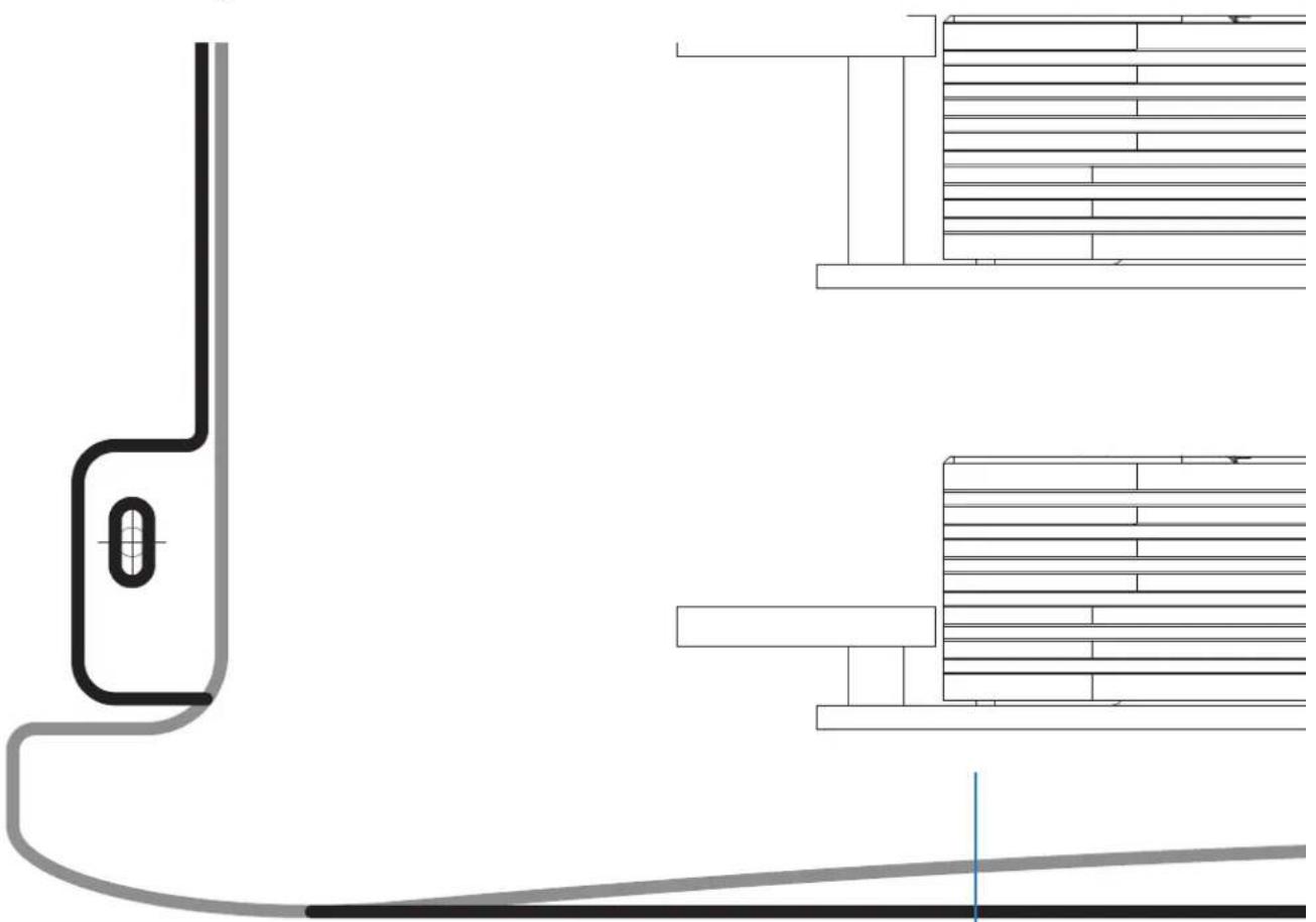
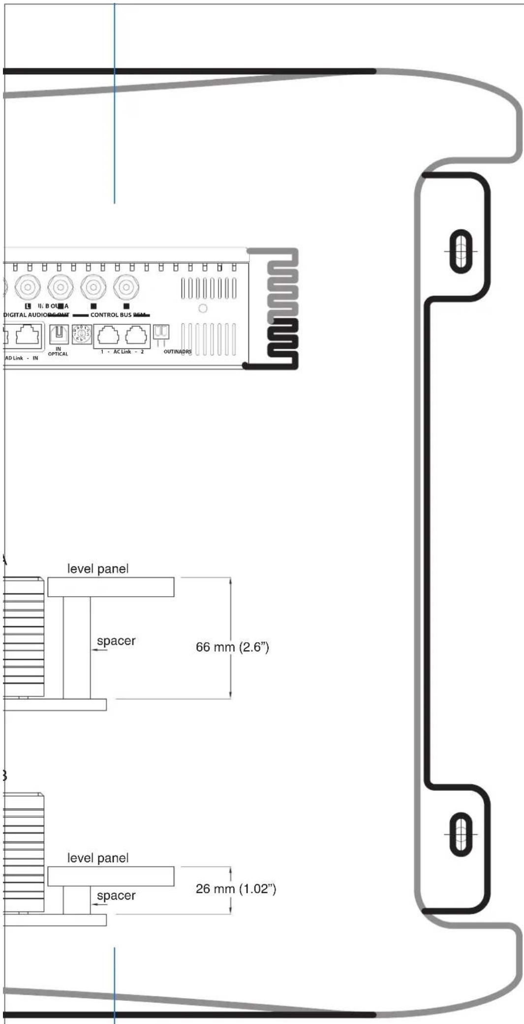
Warning: to properly print the template at the real size, select the "None" option into the "Page Scaling" setup. After printing, cut the sheets along the blue reference line and then glue them.
natural_image
Architectural floor plan showing wall and floor layout with structural elements (no text or labels)THESIS
Fixing template
A B

Rear Panel
Functions Description
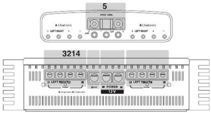
1 • POWER: Positive and negative terminals for 12 V car voltage supply. Size of connectors is 10 mm diameter (2 AWG). Warning: connect positive and negative (GND) with polarity as indicated in the terminal. A wrong connection cause an amplifier damage.
2 • +CAP: Terminal to connect positive pole of external capacitor.
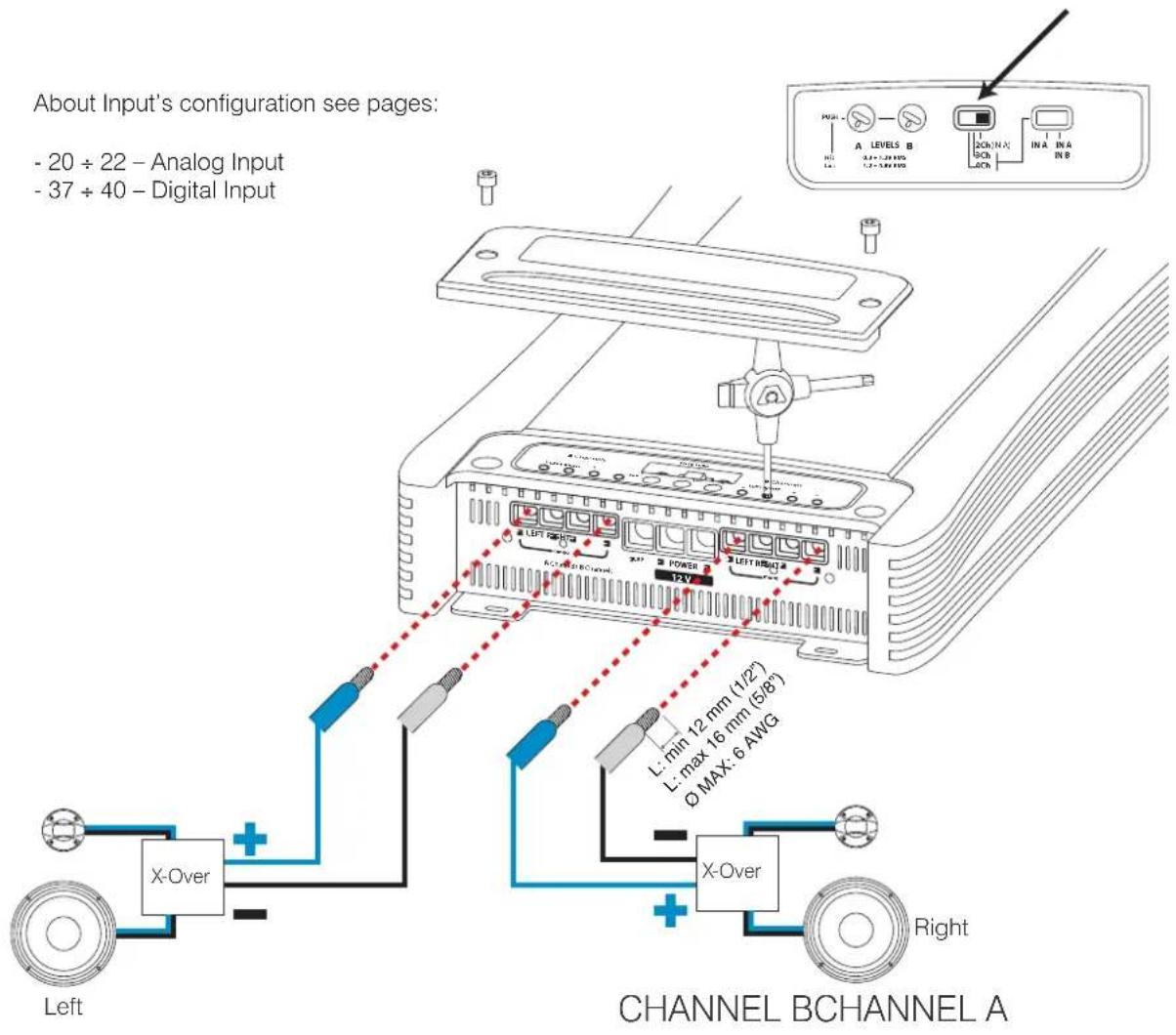
3 • A CHANNELS: Terminals to connect A Channel Left and Right speakers system. Size of connectors is 6 mm (6 AWG). Pay attention to connect speaker with polarity as indicated, wrong polarity causes a phase problem in the audio system.
4 • B CHANNELS: Terminals to connect B Channel Left and Right speakers system. Size of connectors is 6 mm (6 AWG). Pay attention to connect speaker with polarity as indicated, wrong polarity causes a phase problem in the audio system.
5 • FUSE: Protection Fuse Connection Audison AFS 100 A.
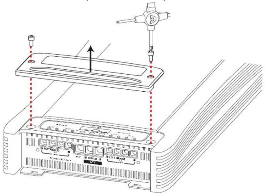
How to remove the panel / the protection knob
Rear Panel
How to connect the power supply
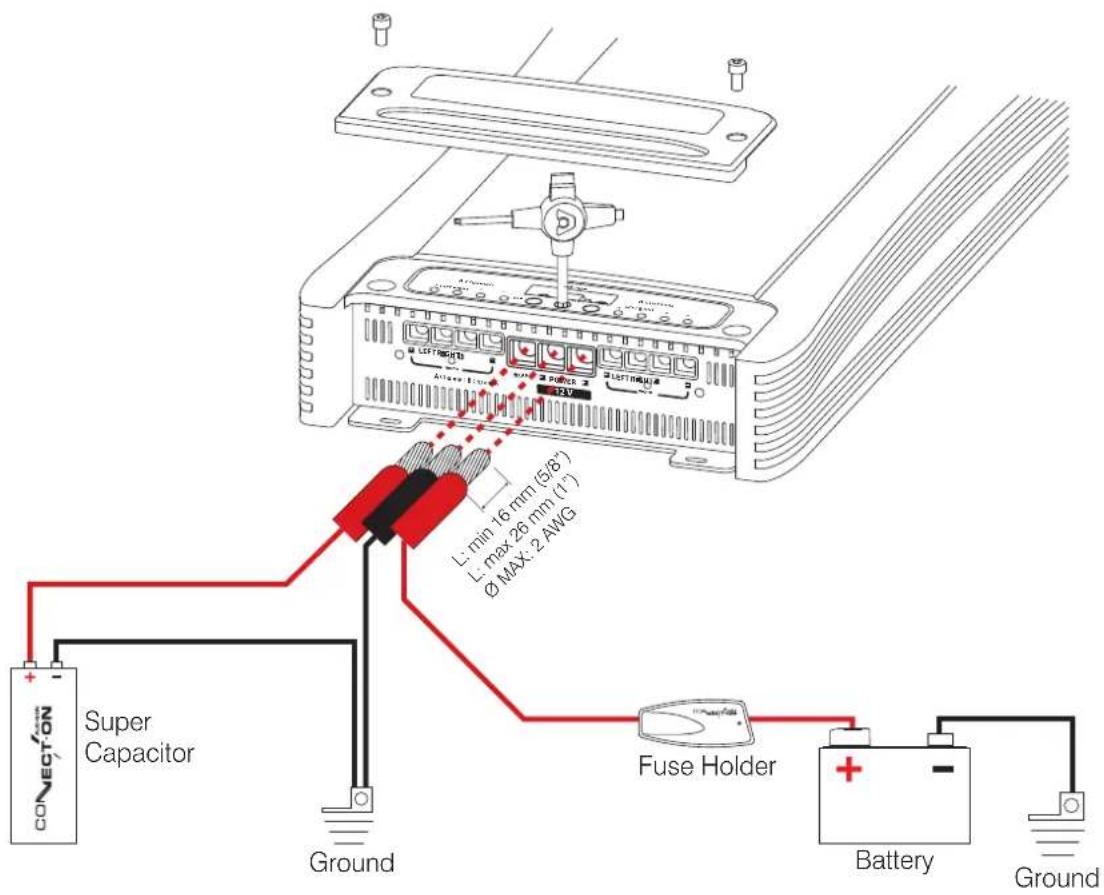
Rear Panel
How to replace the fuse
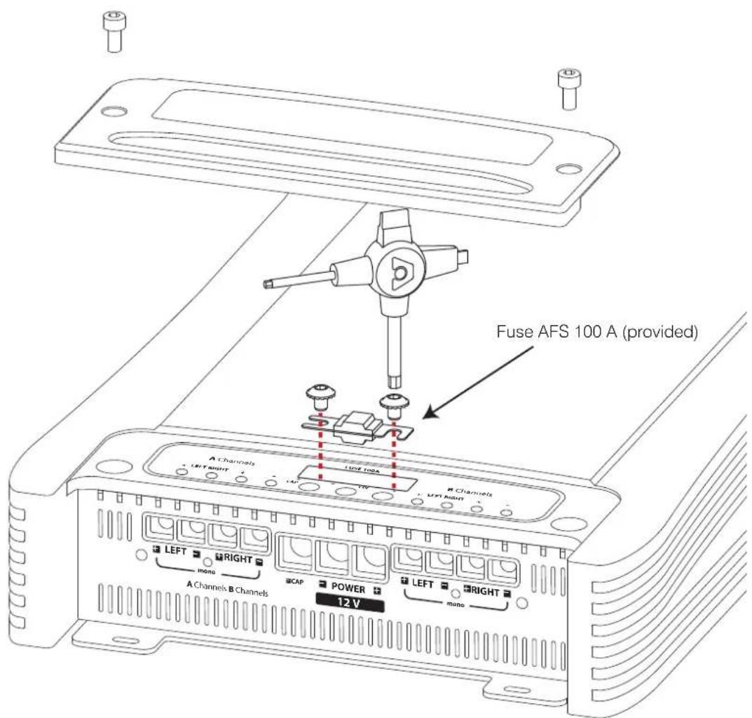
Rear Panel
How to connect the speakers in 4 Ch mode
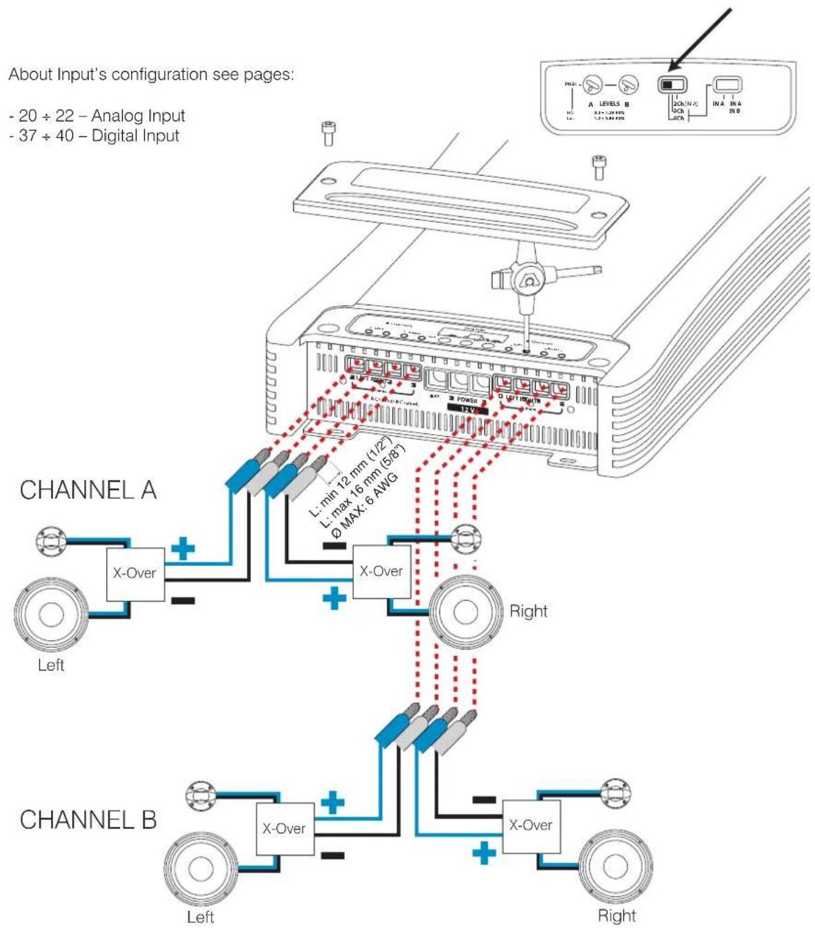
Rear Panel
How to connect the speakers in 3 Ch mode
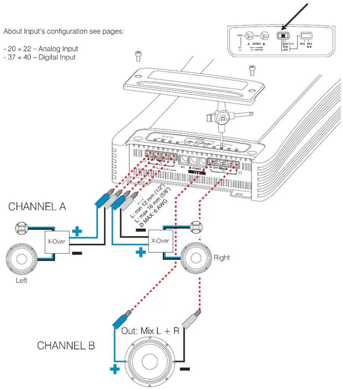
Rear Panel
How to connect the speakers in 2 Ch mode
Input controls
Functions Description
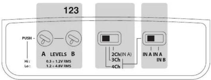
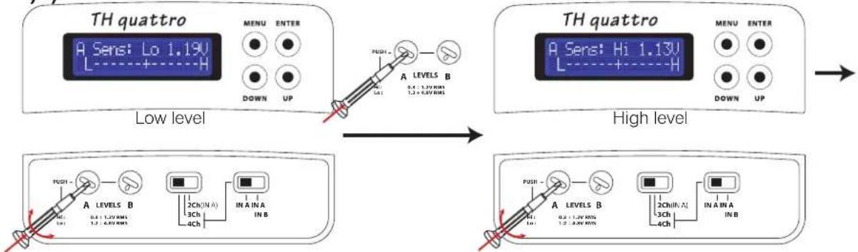
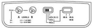
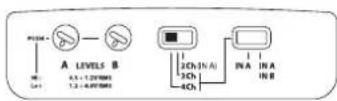
1 • A / B LEVELS: A channels (Left and Right) and B channels (Left and Right) input sensitivity adjustment. It features 2 ranges, Hi from .3 to 1.2 VRMS and Low from 1.2 to 4.8 VRMS. By pushing for three seconds on the knob you can change the range. To see voltage value and range check the ASC display. Those controls are also available if ACNet software is used.
2 • 4 / 3 / 2 Ch Mode: Setting the switch on 4 Ch, the amplifier has to work in 4 channels mode, switching on 3 Ch the B channels will set in mono (Bridge), in 2 Ch position the A channels will set in mono too and the TH quattro has to work in Dual Mono mode.
3 • IN A / IN B: This switch allows to drive the A channels through the IN A inputs and the B channels through the IN B inputs or to drive the amplifier through the IN A inputs. In 2 Ch mode you must use the IN A inputs, IN A Left will drive the A channels (mono) and IN A Right will drive the B channels (mono).
How to move from one sensitivity range to another
1)2)
flowchart
graph LR
    A["Low level: TH quattro with SENS: Lo 1.19V L ----+----H"] --> B["High level: TH quattro with SENS: Hi 1.13V L ----+----H"]
    B --> C["Output: Push - A LEVELS B"]
    C --> D["Low level: PUSH - A LEVELS B"]
    D --> E["High level: Push - A LEVELS B"]
    E --> F["Output: Push - A LEVELS B"]
TURN THE KNOB TO REGULATE THE LEVEL OF THE A CHANNELS. PRESS THE KNOB FOR 3" TO CHANGE THE RANGE FROM HI TO LO AND VICE VERSA. IF YOU ARE USING THE IN B CHANNELS INPUT, REPEAT THE TUNING STEP ON THE B LEVELS KNOB.

WARNING: be careful when passing from LO to HI level!
NOTE: sensitivity is automatically set on the lowest value of Hi Level range, but the difference between the two levels could be dangerous for your system.
Front Panel
Functions Description
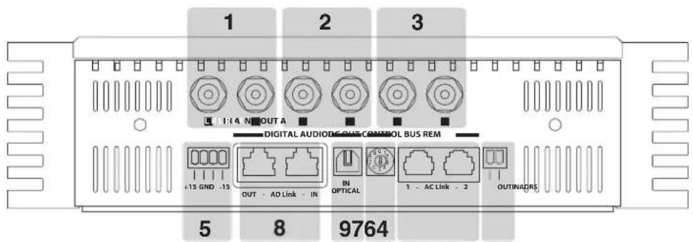
1 • IN A: Analog Left / Right A channels Input
2 • IN B: Analog Left / Right B channels Input
3 • OUT A: Bypass Analog Output Left / Right. It's the same signal of IN A inputs. To check out how they work see page 20 ÷ 22 and 37 ÷ 40
4 • REM IN/OUT: Turn On Remote Input and Output for other devices
5 • DC OUT: ±15 V supply for external devices
CONTROL BUS
6 • AC Link 1 and 2: RJ-12 terminals to connect other devices provided with AC Link such as TH amplifiers, DRC (Digital Remote Control), Audio Digital Processors, AC Link/USB Adapter for Personal Computer connection. The use of connector 1 or 2 is interchangeable. The RJ-12 connectors provided cable is normally used for digital telephone connection but is not compatible with digital telephone technology. It features 6-way connectors. The AC Link connection can give power supply to the amplifier external devices.
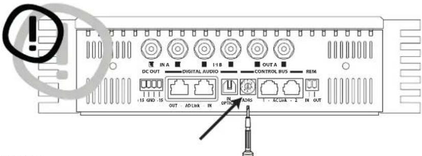
7 • ADRS: It's the digital address of the amplifier when you want to realize a system with more than one TH. Switch selector from 0 to 9 to set in a different number on each TH amplifier of the AC Link network. Maximum allowed chain amplifiers number is 10.
Warning: a different number has to be assigned to each amplifier starting from number zero, otherwise the ACLink network will not work properly. The selected number is shown on the Status display between brackets.
DIGITAL AUDIO IN/OUT
8 • AD Link: is an Audio Digital Bus that can carry 8 channels. It employs a Class 5 or 6 shielded Ethernet LAN cable with the provided shielded connectors, normally used in computer networks.
- AD Link IN: RJ-45 terminal input to connect digital audio coming from previous TH amplifier or the provided external device AD Link such as Digital Audio Processor (bit one / bit Ten D).
- AD Link OUT: RJ-45 terminal output to connect to the next TH amplifier.
9 • OPTICAL IN: Input to connect the provided optical cable with TOSLINK connectors. The optical audio digital signal in S/PDIF standard is supplied from provided sources such as CD/DVD players. It accepts input PCM stereo signals up to 192 kHz / 24 bit.
Front Panel
How to connect the remote
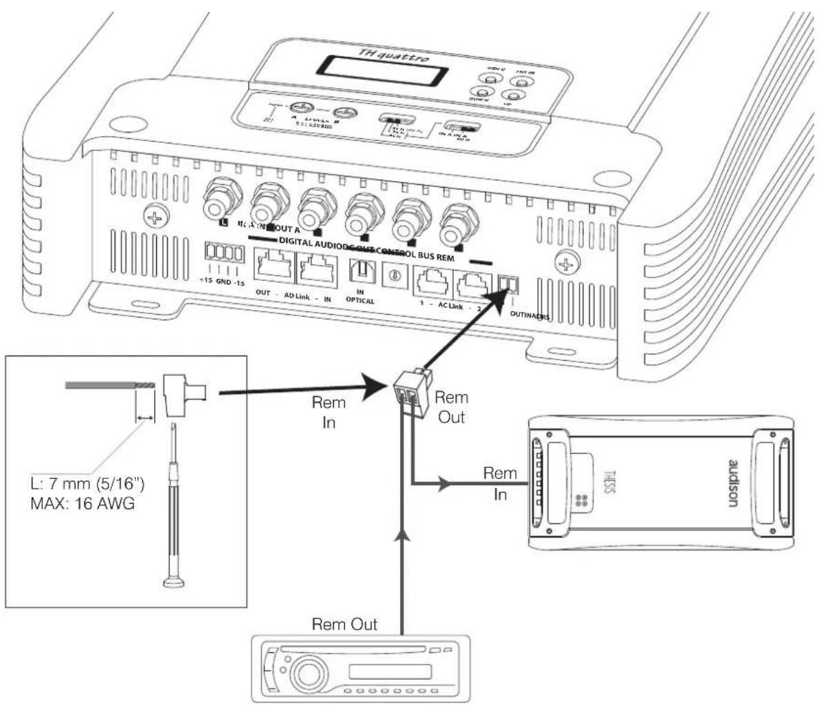
Front Panel
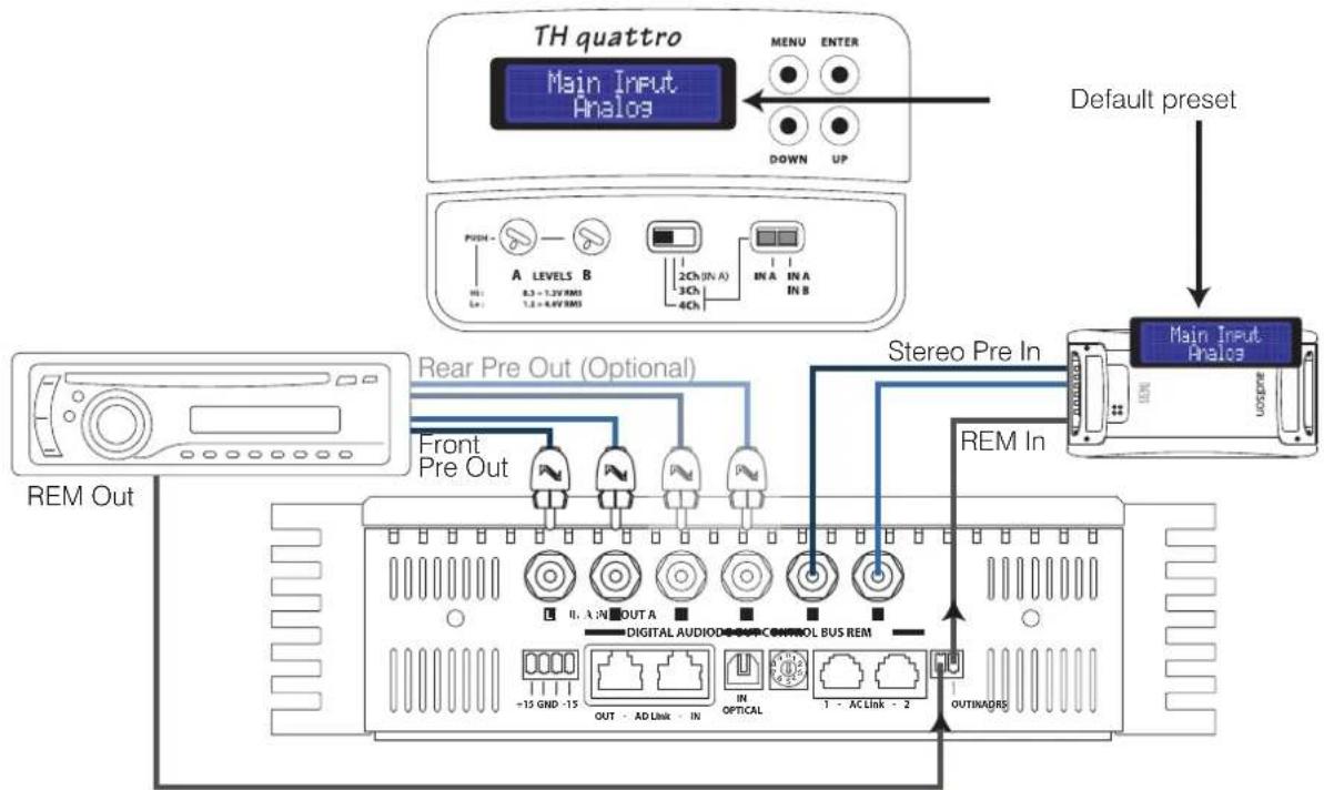
How to connect the source through the preamplified analog input (standard mode)
TH configured in 4 Ch mode
Input: IN A (and IN B) Stereo Analog
Pre Out: Stereo Analog (=IN A)
Power Output: 4 Channels
A Channels: Stereo
B Channels: Stereo
flowchart
graph TD
    A["TH quattro Main Input Analos"] --> B["Default preset"]
    B --> C["Main Input Analos"]
    D["REMA OUT"] --> E["Rear Pre Out (Optional)"]
    E --> F["Front Pre Out"]
    F --> G["Rem In"]
    G --> H["Stereo Pre In"]
    H --> I["OUTRADRS"]
    J["MAIN INDEUT"] --> K["MAIN INDEUT"]
    L["MAIN INDEUT"] --> M["MAIN INDEUT"]
    N["MAIN INDEUT"] --> O["MAIN INDEUT"]
    P["MAIN INDEUT"] --> Q["MAIN INDEUT"]
    R["MAIN INDEUT"] --> S["MAIN INDEUT"]
    T["MAIN INDEUT"] --> U["MAIN INDEUT"]
    V["MAIN INDEUT"] --> W["MAIN INDEUT"]
    X["MAIN INDEUT"] --> Y["MAIN INDEUT"]
    Z["MAIN INDEUT"] --> AA["MAIN INDEUT"]
Power Output: to carry out connections, check page 14 ÷ 16
DRC: not required
PRE OUT: To cascade-connect other amplifiers when using the analog input you MUST use the Pre Out analog output.

Front Panel
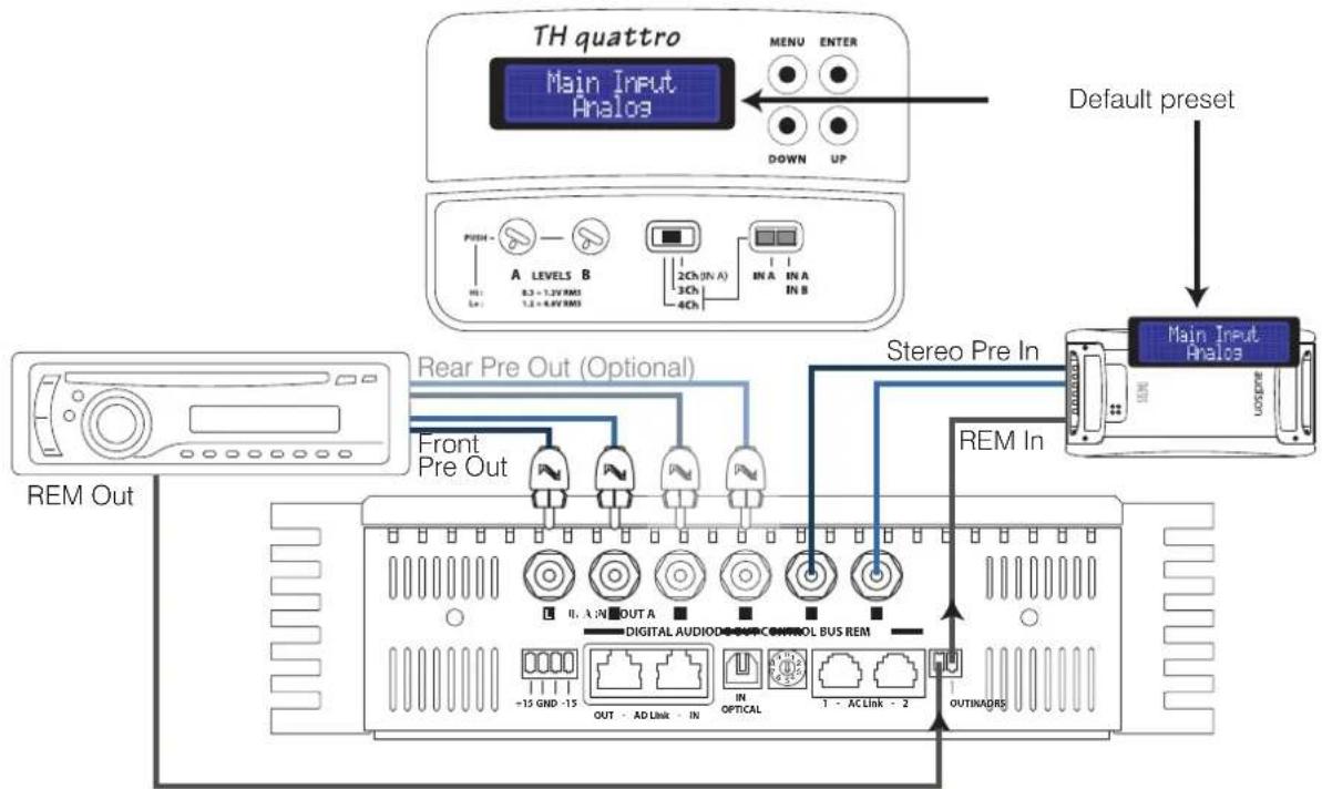
How to connect the source through the preamplified analog input (standard mode)
TH configured in 3 Ch mode
Input: IN A (and IN B) Stereo Analog
Pre Out: Stereo Analog (=IN A)
Power Output: 3 Channels
A Channels: Stereo
B Channels: Mono (MIX L+R)
flowchart
graph TD
    A["TH quattro Main Input Analos"] --> B["Default preset"]
    B --> C["Main Input Analos"]
    D["REMA OUT"] --> E["Rear Pre Out (Optional)"]
    E --> F["Front Pre Out"]
    F --> G["Rem In"]
    G --> H["Stereo Pre In"]
    H --> I["OUTRADRS"]
    J["MAIN IN A"] --> K["Digital Audio Control Bus REM"]
    L["MAIN IN B"] --> M["2Ch (IN A) 3Ch 4Ch"]
    N["MAIN IN C"] --> O["OUT A OUT A"]
    P["MAIN IN D"] --> Q["OUT - AD Link IN"]
    R["MAIN IN E"] --> S["IN OPTICAL 1 - AC Link - 2"]
    T["MAIN IN F"] --> U["OUT - 15 GND - 15 OUT - AD Link IN"]
Power Output: to carry out connections, check page 14 ÷ 16
DRC: not required
PRE OUT: To cascade-connect other amplifiers when using the analog input you MUST use the Pre Out analog output.

Front Panel
How to connect the source through the preamplified analog input (standard mode)
TH configured in 2 Ch mode
Input: IN A Stereo Analog
Pre Out: Stereo Analog (=IN A)
Power Output: 2 Channels
A Channels: Mono (IN A Left)
B Channels: Mono (IN A Right)
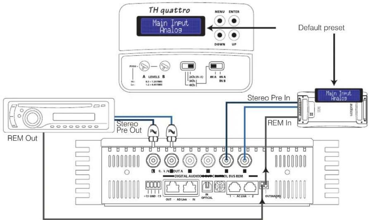
flowchart
graph TD
    A["TH quattro Main Input Analos"] --> B["Default preset"]
    B --> C["Main Input Analos"]
    D["REMO OUT"] --> E["Stereo Pre Out"]
    E --> F["Rem In"]
    G["MAIN INPUT Analos"] --> H["Default preset"]
    H --> I["Main Input Analos"]
    style A fill:#f9f,stroke:#333
    style B fill:#ccf,stroke:#333
    style C fill:#cfc,stroke:#333
    style D fill:#fcc,stroke:#333
    style E fill:#cff,stroke:#333
    style F fill:#ffc,stroke:#333
    style G fill:#fcc,stroke:#333
    style H fill:#cfc,stroke:#333
Power Output: to carry out connections, check page 14 ÷ 16
DRC: not required
PRE OUT: To cascade-connect other amplifiers when using the analog input you MUST use the Pre Out analog output.

Electronic Crossover
Representing a high-end solution, the simplicity and power of the analog system found in the HV venti is thrust forward again in the TH, making use of the amplifiers versatility.

The crossover ONLY acts on the amplifier power output, not on the PRE OUT output which is always a bypass.
The alignment is a Butterworth type as, when either of the TH amplifiers is set up in a mono configuration, the slope of the filter can be set for 24 dB Oct operation.
Each TH quattro is factory provided with:
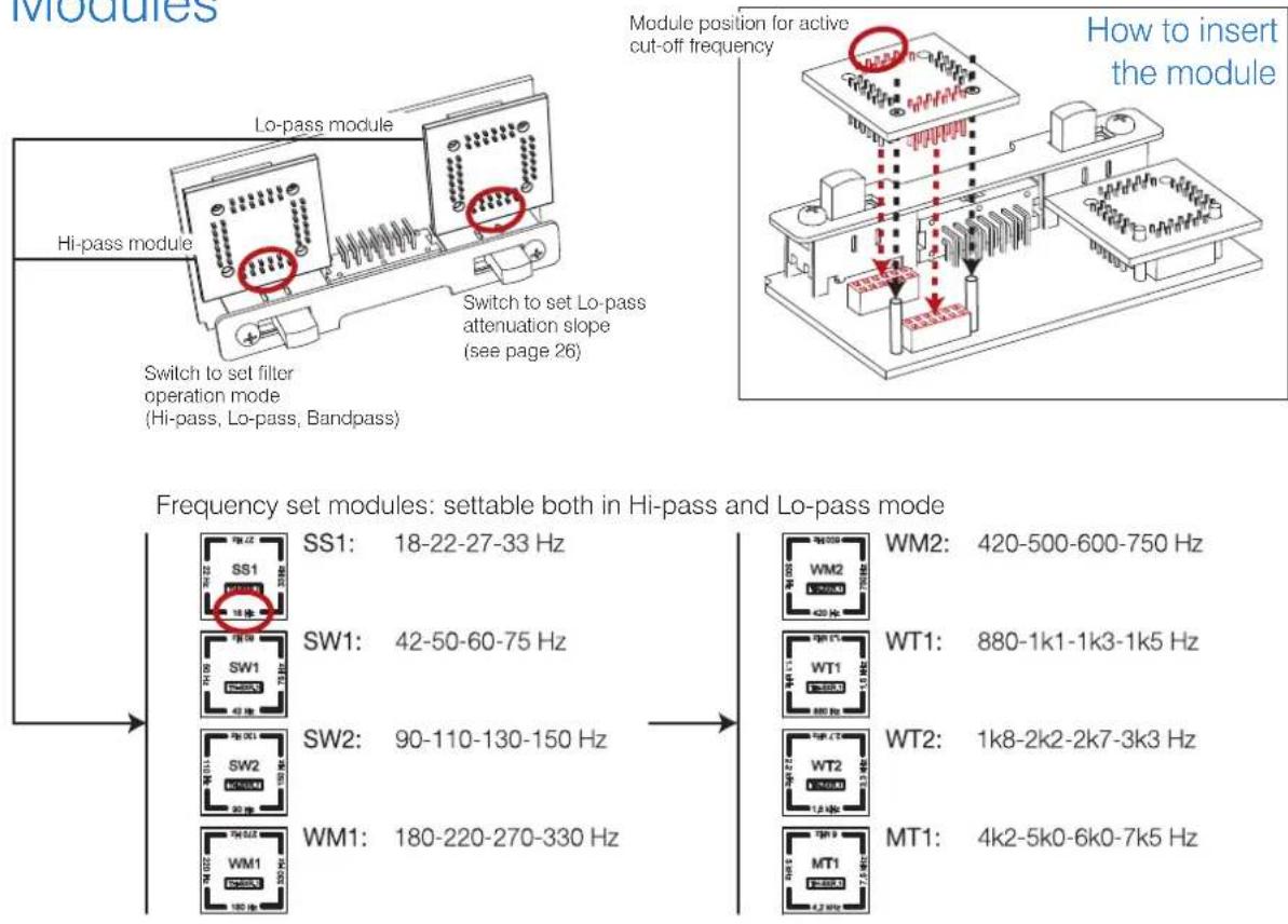
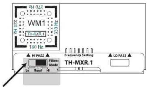
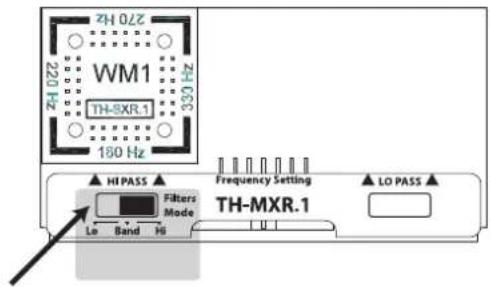
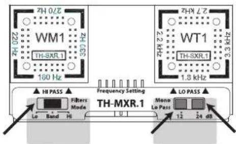
- a pair TH-MXR.1 crossover board, containing the electronics required to set, through selectors, the operation mode as well as the Low-Pass filter slope.
- two pair of eight crossover modules each, featuring high-precision resistor packs corresponding to 32 cut-off frequencies placed at equal distance from 18Hz thru 7.5kHz.
- four customisable crossover modules (to build them, see the "Custom Module" section in this manual).
Modules
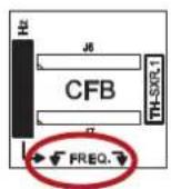
Custom Module
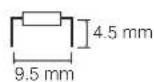
$$ \text { Res } (k \Omega) = \frac {5 0 0 0}{\text { Freq } (\mathrm{Hz})} $$
$$ \text { Example: Desired cut - off frequency } = 2. 5 \mathrm{kHz} \quad \xrightarrow [ 2 5 0 0 ]{5 0 0 0} \frac {\text { Resistor's value to use }}{- 2 \mathrm{k} \Omega} $$
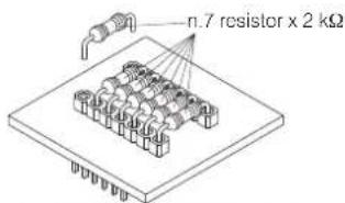
Use 1 % tolerance 0.25 W resistors
Electronic Crossover
TH in 4 Ch Mode
Filtering A channels and B channels
TH in 3 Ch Mode
Filtering A channels
BY-PASS
DO NOT INSERT
TH-MXR.1MODULE
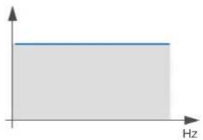
line
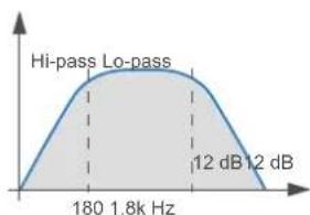
| Frequency (Hz) | Value | |---|---| | 0 | 0.5 | | 1 | 0.5 | | 2 | 0.5 | | 3 | 0.5 | | 4 | 0.5 | | 5 | 0.5 | | 6 | 0.5 | | 7 | 0.5 | | 8 | 0.5 | | 9 | 0.5 | | 10 | 0.5 | | 11 | 0.5 | | 12 | 0.5 | | 13 | 0.5 | | 14 | 0.5 | | 15 | 0.5 | | 16 | 0.5 | | 17 | 0.5 | | 18 | 0.5 | | 19 | 0.5 | | 20 | 0.5 | | 21 | 0.5 | | 22 | 0.5 | | 23 | 0.5 | | 24 | 0.5 | | 25 | 0.5 | | 26 | 0.5 | | 27 | 0.5 | | 28 | 0.5 | | 29 | 0.5 | | 30 | 0.5 | | 31 | 0.5 | | 32 | 0.5 | | 33 | 0.5 | | 34 | 0.5 | | 35 | 0.5 | | 36 | 0.5 | | 37 | 0.5 | | 38 | 0.5 | | 39 | 0.5 | | 40 | 0.5 | | 41 | 0.5 | | 42 | 0.5 | | 43 | 0.5 | | 44 | 0.5 | | 45 | 0.5 | | 46 | 0.5 | | 47 | 0.5 | | 48 | 0.5 | | 49 | 0.5 | | 50 | 0.5 | | 51 | 0.5 | | 52 | 0.5 | | 53 | 0.5 | | 54 | 0.5 | | 55 | 0.5 | | 56 | 0.5 | | 57 | 0.5 | | 58 | 0.5 | | 59 | 0.5 | | 60 | 0.5 | | 61 | 0.5 | | 62 | 0.5 | | 63 | 0.5 | | 64 | 0.5 | | 65 | 0.5 | | 66 | 0.5 | | 67 | 0.5 | | 68 | 0.5 | | 69 | 0.5 | | 70 | 0.5 | | 71 | 0.5 | | 72 | 0.5 | | 73 | 0.5 | | 74 | 0.5 | | 75 | 0.5 | | 76 | 0.5 | | 77 | 0.5 | | 78 | 0.5 | | 79 | 0.5 | | 80 | 0.5 | | 81 | 0.5 | | 82 | 0.5 | | 83 | 0.5 | | 84 | 0.5 | | 85 | 0.5 | | 86 | 0.5 | | 87 | 0.5 | | 88 | 0.5 | | 89 | 0.5 | | 90 | 0.5 | | 91 | 0.5 | | 92 | 0.5 | | 93 | 0.5 | | 94 | 0.5 | | 95 | 0.5 | | 96 | 0.5 | | 97 | 0.5 | | 98 | 0.5 | | 99 | 0.5 | |100 | -1 |HI-PASS
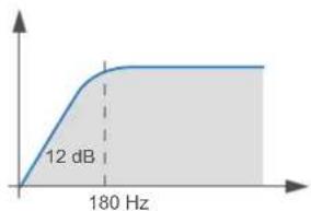
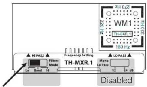
line
| Frequency | Value | | --------- | ----- | | 12 Hz | 12 dB |LO-PASS
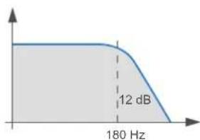
line
| Frequency | Value | | --------- | ----- | | 180 Hz | 12 dB |BANDPASS
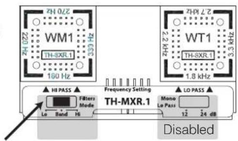
line
| Frequency | Gain (dB) | | --------- | --------- | | 180 | 0 | | 1.8k | 12 | | 1.2 | 12 |Electronic Crossover
TH in 3 Ch Mode
Filtering B channels
TH in 2 Ch Mode
Filtering A channels (Left) and B channels (Right)
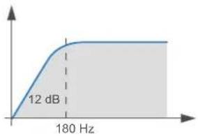
Setup Xover Slope 12 dB (default configuration)
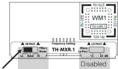
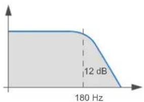
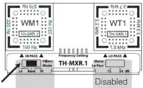
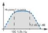
When the amplifier is set up in a mono configuration, it is possible to set the crossover slope at 12 or 24 dB/Oct.
- The TH-MXR.1 board must be inserted;
- You need to operate on the ASC specific Setup Amplifier step. (See page 46).
Through the Status Monitor it is possible to check anytime the presence of the filter as well as the set slope.
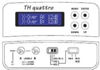
HI-PASS
line
| Frequency | Amplitude | | --------- | --------- | | 0 | 0 | | 180 Hz | 12 dB |LO-PASS
line
| Frequency | Value | | --------- | ----- | | 180 Hz | 12 dB |BANDPASS

line
| Frequency | Gain (dB) | | --------- | --------- | | 180 | 12 | | 1.8kHz | 12 |Electronic Crossover
TH in 3 Ch Mode Filtering B channels
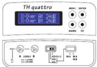
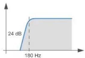
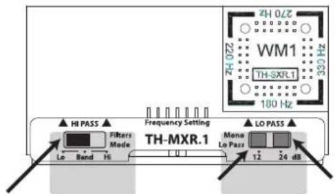
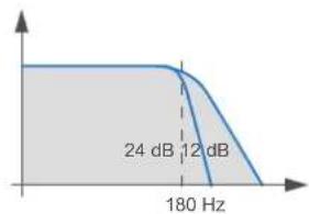
Setup Lo-pass Xover Slope 24 dB
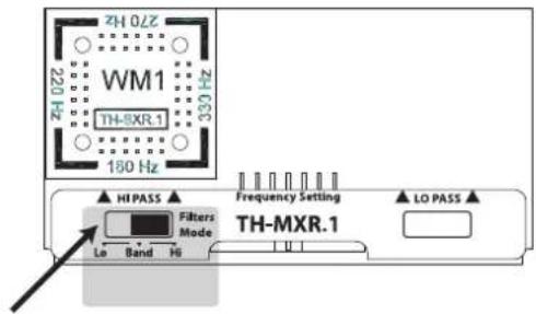
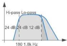
When the amplifier is set up in a mono configuration, and ASC is set at 24 dB Oct., it is anyway possible to set the crossover Low-pass at 12 or 24 dB Oct.
- The TH-MXR.1 board must be inserted;
- You need to operate on the TH-MXR.1 switch. Through the Status Monitor it is possible to check anytime the presence of the filter as well as the set slope.
HI-PASS
line
| Frequency | Value | | --------- | ----- | | 180 Hz | 24 dB |LO-PASS
line
| Frequency | Amplitude | | --------- | --------- | | 180 Hz | 24 dB | | 180 Hz | 12 dB |BANDPASS
line
| Frequency | Value | | --------- | ----- | | 24 dB | 24 dB | | 12 dB | 12 dB |Electronic Crossover
How to insert
Not inserted module (default configuration)
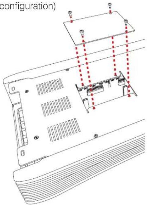
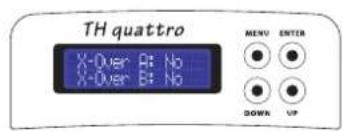
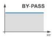
You can verify the crossover presence by checking the ASC Status Monitor. See page 53
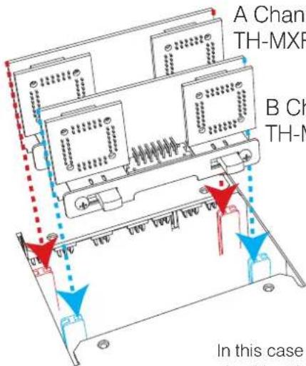
A Channels TH-MXR.1 module
B Channels TH-MXR.1 module
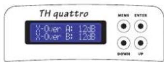
In this case you can verify both presence and slope of the crossover by checking the ASC Status Monitor, however it is not possible to modify its slope. See page 53.
Example: Two Way, multi-amplified, TH amplifier Analog Input
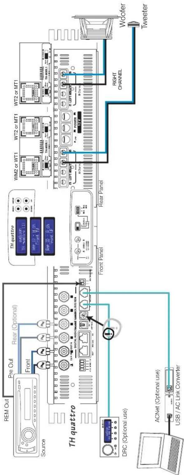
In order to build a Standard System you have to:
1- Insert the TH-MXR.1 boards with its relative filter modules (if required);
2- Connect power supply;
3- Connect the speaker system;
4- Connect signal inputs (IN A or IN A / IN B) and remote turn on;
5- Select 4 Ch mode on the Input Controls Panel (select IN A or IN A / IN B);
6- Adjust sensitivity on the Input Controls Panel "A LEVEL" or "A/B LEVEL";
In order to add DRC to the System you also need to:
7- Set ADRS on the Front Panel (in position 1 for instance);
8- Set Amp ID for A channels (on FRONT TW for instance) and B channels (on FRONT WF for instance) in the ASC Setup Amplifier; this way DRC will be enabled to adjust general Volume, Balance and Fader.
In order to adjust the system through the ACNet:
On this system the steps 1, 2, 3, 4, 5 and 7 need to be performed.
The Software will temporarily bypass the DRC functionality in order to manage in a more direct and easier way all of the amplifier functions during the adjustment and modifying phases, including input sensitivity adjustment along with peak detector.
REMARK:
Into the amplifier ASC, the Dual Power and Runtime Monitor functions will anyway stay active (by default) and ready to change it directly (see page 52 and following pages).
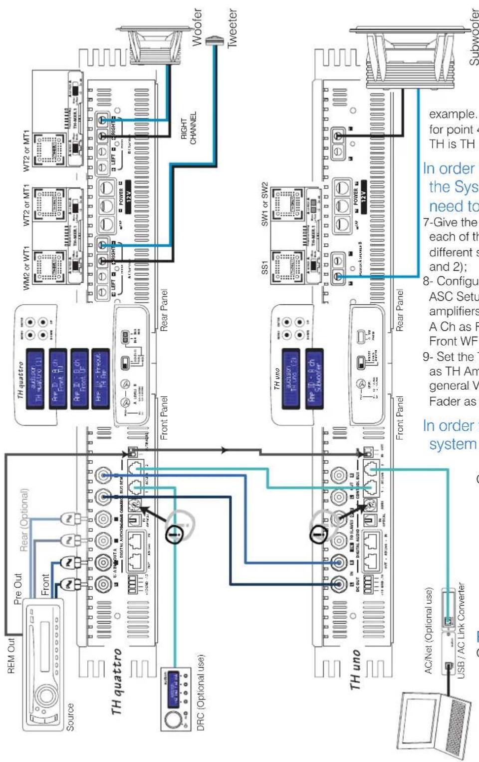
Example: Two Way+Sub, multi-amplified, TH amplifier Analog Input
Subwoofer
In order to build a Standard System:
You have to follow same steps as per the above
example. The only difference is for point 4, where the second TH is TH uno (mono);
In order to add DRC to the System you also need to:
7-Give the Front Panel ADRS of each of the two amplifiers a different setting (Example: 1 and 2);
8- Configure the Amp ID on the ASC Setup Amplifier of the two amplifiers by setting TH quattro A Ch as Front TW and B Ch as Front WF and TH uno as Sub;
9- Set the TH quattro ID Preout as TH Amp, to let DRC adjust general Volume, Balance, Fader as well as Sub Volume.
In order to adjust the system through the
ACNet:
Once the steps 1, 2, 3, 4, 5 and 7 have been performed, the Software will temporarily bypass the DRC in order to manage in a more direct and easier way all of the system functions.
REMARK:
On ASC Dual Power and Runtime Monitor will anyway stay active (by default) and ready for changes (see page 47 and following pages).
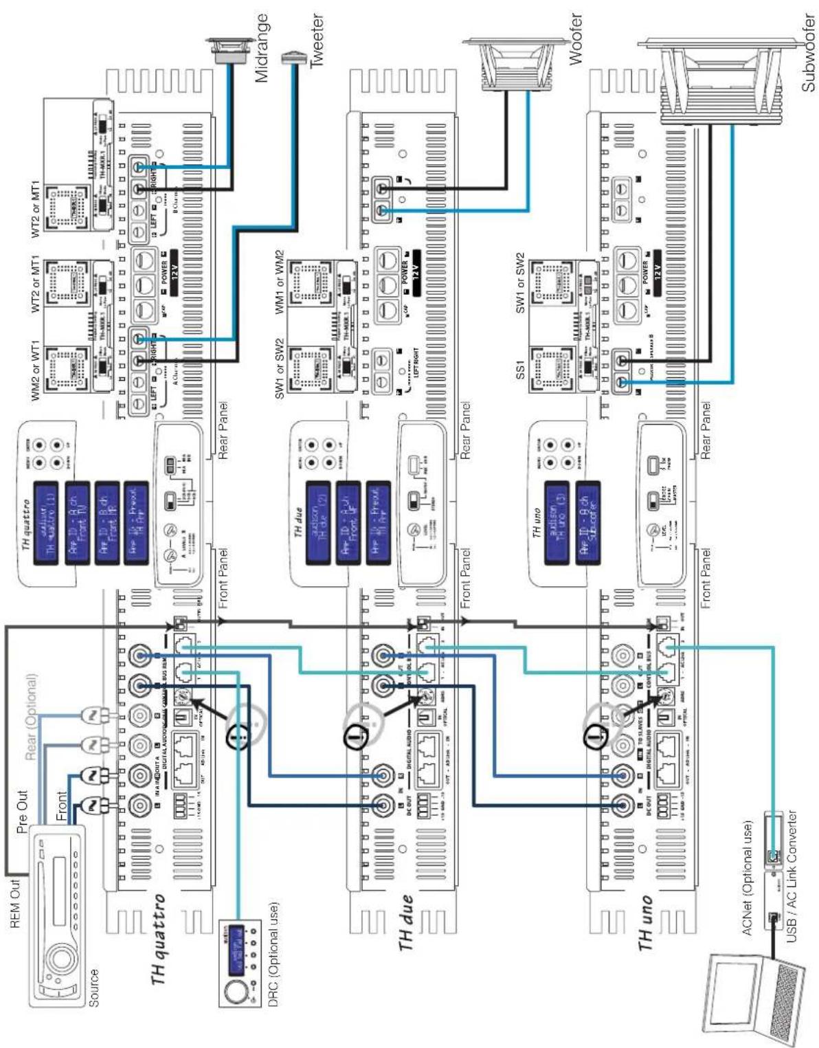
Example: Three Way + Sub, multi-amplified, TH amplifier Analog Input
flowchart
graph TD
    A["Source"] --> B["TH quattro"]
    B --> C["TH due"]
    C --> D["TH uno"]
    D --> E["ACNet (Optional use)"]
    B --> F["TH quattro"]
    F --> G["TH due"]
    G --> H["TH uno"]
    H --> I["Subwoofer"]

    subgraph TH_quattro
        J["REM Out"] --> K["Pre Out"]
        K --> L["Rear (Optional)"]
        L --> M["Front"]
        M --> N["INAM OUTA"]
        N --> O["DIGITAL AUDIO & COMMERCIAL BUS REM"]
        O --> P["1X 20Hz 14"]
        P --> Q["DC OUT"]
        Q --> R["DC OUT"]
        R --> S["DC OUT"]
        S --> T["DC OUT"]
        T --> U["DC OUT"]
        U --> V["DC OUT"]
        V --> W["DC OUT"]
        W --> X["DC OUT"]
        X --> Y["DC OUT"]
        Y --> Z["DC OUT"]
        Z --> AA["DC OUT"]
        AA --> AB["DC OUT"]
        AB --> AC["DC OUT"]
        AC --> AD["DC OUT"]
        AD --> AE["DC OUT"]
        AE --> AF["DC OUT"]
        AF --> AG["DC OUT"]
        AG --> AH["DC OUT"]
        AH --> AI["DC OUT"]
        AI --> AJ["DC OUT"]
        AJ --> AK["DC OUT"]
        AK --> AL["DC OUT"]
        AL --> AM["DC OUT"]
        AM --> AN["DC OUT"]
        AN --> AO["DC OUT"]
        AO --> AP["DC OUT"]
        AP --> AQ["DC OUT"]
        AQ --> AR["DC OUT"]
        AR --> AS["DC OUT"]
        AS --> AT["DC OUT"]
        AT --> AU["DC OUT"]
        AU --> AV["DC OUT"]
        AV --> AW["DC OUT"]
        AW --> AX["DC OUT"]
        AX --> AY["DC OUT"]
        AY --> AZ["DC OUT"]
        AZ --> BA["DC OUT"]
        BA --> BB["DC OUT"]
        BB --> BC["DC OUT"]
        BC --> BD["DC OUT"]
        BD --> BE["DC OUT"]
        BE --> BF["DC OUT"]
        BF --> BG["DC OUT"]
        BG --> BH["DC OUT"]
        BH --> BI["DC OUT"]
        BI --> BJ["DC OUT"]
        BJ --> BK["DC OUT"]
        BK --> BL["DC OUT"]
        BL --> BM["DC OUT"]
        BM --> BN["DC OUT"]
        BN --> BO["DC OUT"]
        BO --> BP["DC OUT"]
        BP --> BQ["DC OUT"]
        BQ --> BR["DC OUT"]
        BR --> BS["DC OUT"]
        BS --> BT["DC OUT"]
        BT --> BU["DC OUT"]
        BU --> BV["DC OUT"]
        BV --> BW["DC OUT"]
        BW --> BX["DC OUT"]
        BX --> BY["DC OUT"]
        BY --> BZ["DC OUT"]
        BZ --> CA["DC OUT"]
        CA --> CB["DC OUT"]
        CB --> CC["DC OUT"]
        CC --> CD["DC OUT"]
        CD --> CE["DC OUT"]
        CE --> CF["DC OUT"]
        CF --> CG["DC OUT"]
        CG --> CH["DC OUT"]
        CH --> CI["DC OUT"]
        CI --> CJ["DC OUT"]
        CJ --> CK["DC OUT"]
        CK --> CL["DC OUT"]
        CL --> CM["DC OUT"]
        CM --> CN["DC OUT"]
        CN --> CO["DC OUT"]
        CO --> CP["DC OUT"]
        CP --> CQ["DC OUT"]
        CQ --> CR["DC OUT"]
        CR --> CS["DC OUT"]
        CS --> CT["DC OUT"]
        CT --> CU["DC OUT"]
        CU --> CV["DC OUT"]
        CV --> CW["DC OUT"]
        CW --> CX["DC OUT"]
        CX --> CY["DC OUT"]
        CY --> CZ["DC OUT"]
        CZ --> DA["DC OUT"]
        DA --> DB["DC OUT"]
        DB --> DC
    end

    subgraph TH_due
        E["TH due"] --> F["TW1 or SW2"] & G["WMI or WM2"] & H["Midrange"] & I["Tweeter"]

    subgraph TH_uno
        J["TH uno"] & K["WOOFER"] & L["S1"] & M["SW1 or SW2"] & N["SW1 or SW2"] & O["SW1 or SW2"] & P["SW1 or SW2"] & Q["SW1 or SW2"] & R["SW1 or SW2"] & S["SW1 or SW2"] & T["SW1 or SW2"] & U["SW1 or SW2"] & V["SW1 or SW2"] & W["SW1 or SW2"] & X["SW1 or SW2"] & Y["SW1 or SW2"] & Z["SW1 or SW2"] & AA["SW1 or SW2"] & AB["SW1 or SW2"] & AC["SW1 or SW2"] & AD["SW1 or SW2"] & AE["SW1 or SW2"] & AF["SW1 or SW2"] & AG["SW1 or SW2"] & AH["SW1 or SW2"] & AI["SW1 or SW2"] & AJ["SW1 or SW2"] & AK["SW1 or SW2"] & AL["SW1 or SW2"] & AM["SW1 or SW2"] & AN["SW1 or SW2"] & AO["SW1 or SW2"] & AP["SW1 or SW2"] & AQ["SW1 or SW2"] & AR["SW1 or SW2"] & AS["SW1 or SW2"] & AT["SW1 or SW2"] & AU["SW1 or SW2"] & AV["SW1 or SW2"] & AW["SW1 or SW2"] & AX["SW1 or SW2"] & AY["SW1 or SW2"] & AZ["SW1 or SW2"] & BA["SW1 or SW2"] & BB["SW1 or SW2"] & BC["SW1 or SW2"] & BD["SW1 or SW2"] & BE["SW1 or SW2"] & BF["SW1 or SW2"] & BG["SW1 or SW2"] & BH["SW1 or SW2"] & BI["SW1 or SW2"] & BJ["SW1 or SW2"] & BK["SW1 or SW2"] & BL["SW1 or SW2"] & BK_Swier

    J <--> K
    K <--> L
    L <--> M
    M <--> N
    N <--> O
    O <--> P
    P <--> Q
    Q <--> R
    R <--> S
    S <--> T
    T <--> U
    U <--> V
    V <--> W
    W <--> X
    X <--> Y
    Y <--> Z
    Z <--> AA
    AA <--> AB
    AB <--> AC
    AC <--> AD
    AD <--> AE
    AE <--> AF
    AF <--> AG
    AG <--> AH
    AH <--> AI
    AI <--> AJ
    AJ <--> AK
    AK <--> AL
    AL <--> AM
    AM <--> AN
    AN <--> AO
    AO <--> AP
    AP <--> AQ
    AQ <--> AR
    AR <--> AS
    AS <--> AT
    AT <--> AU
    AU <--> AV
    AV <--> AW
    AW <--> AX
    AX <--> AY
    AY <--> AZ
    AZ <--> BA
Classic domain
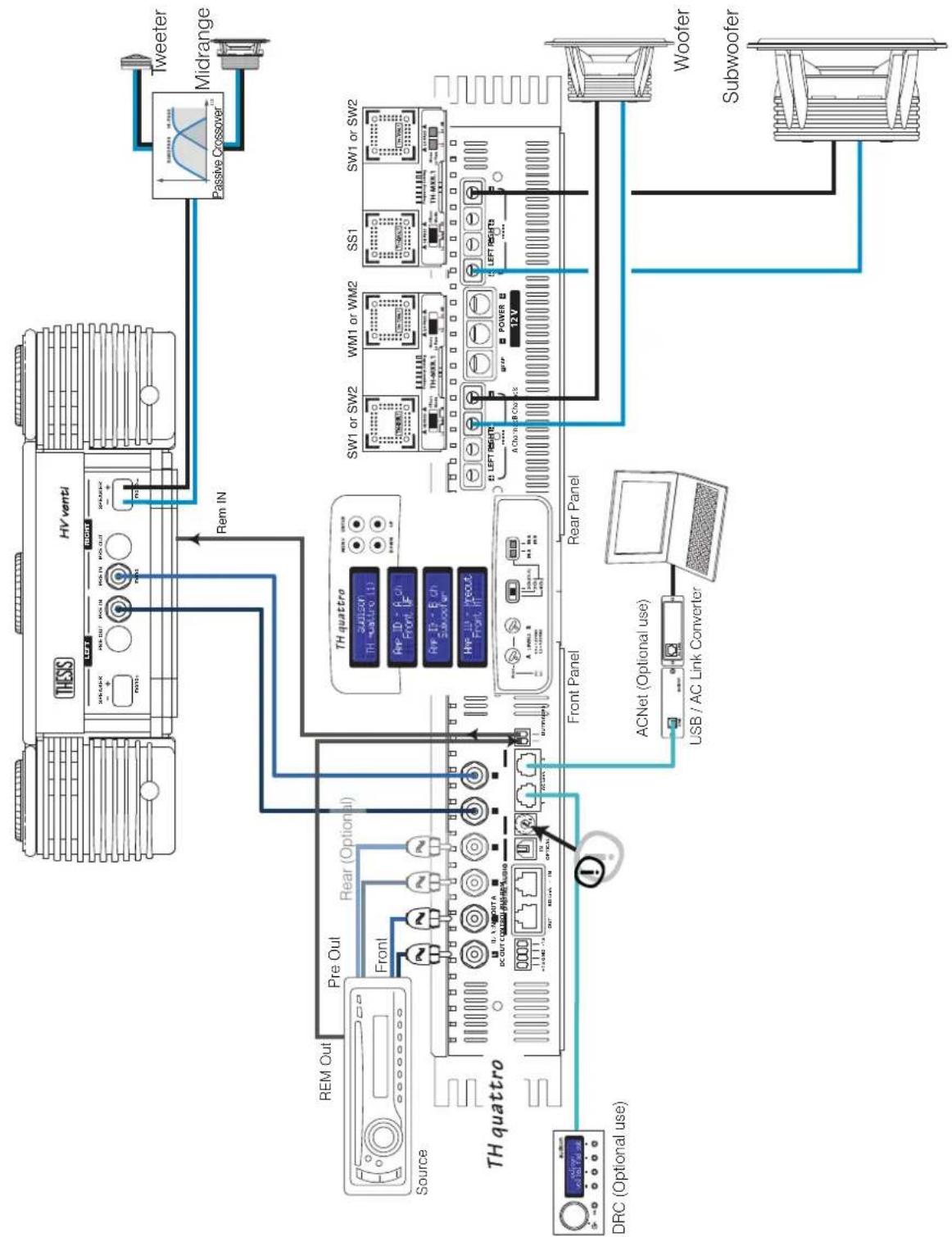
Example: Three Way + Sub, multi-amplified, with and without TH amplifiers. Analog Input
flowchart
graph TD
    A["TH quattro"] -->|Front Panel| B["TH trimester"]
    A -->|Front Panel| C["ACNet (Optional use)"]
    A -->|Front Panel| D["Subwoofer"]
    A -->|Front Panel| E["Woofer"]
    A -->|Front Panel| F["Switch 12V"]
    A -->|Front Panel| G["Switch 12V"]
    A -->|Front Panel| H["Switch 12V"]
    A -->|Front Panel| I["Switch 12V"]
    A -->|Front Panel| J["Switch 12V"]
    A -->|Front Panel| K["Switch 12V"]
    A -->|Front Panel| L["Switch 12V"]
    A -->|Front Panel| M["Switch 12V"]
    A -->|Front Panel| N["Switch 12V"]
    A -->|Front Panel| O["Switch 12V"]
    A -->|Front Panel| P["Switch 12V"]
    A -->|Front Panel| Q["Switch 12V"]
    A -->|Front Panel| R["Switch 12V"]
    A -->|Front Panel| S["Switch 12V"]
    A -->|Front Panel| T["Switch 12V"]
    A -->|Front Panel| U["Switch 12V"]
    A -->|Front Panel| V["Switch 12V"]
    A -->|Front Panel| W["Switch 12V"]
    A -->|Front Panel| X["Switch 12V"]
    A -->|Front Panel| Y["Switch 12V"]
    A -->|Front Panel| Z["Switch 12V"]
    A -->|Front Panel| AA["Switch 12V"]
    A -->|Front Panel| AB["Switch 12V"]
    A -->|Front Panel| AC["Switch 12V"]
    A -->|Front Panel| AD["Switch 12V"]
    A -->|Front Panel| AE["Switch 12V"]
    A -->|Front Panel| AF["Switch 12V"]
    A -->|Front Panel| AG["Switch 12V"]
    A -->|Front Panel| AH["Switch 12V"]
    A -->|Front Panel| AI["Switch 12V"]
    A -->|Front Panel| AJ["Switch 12V"]
    A -->|Front Panel| AK["Switch 12V"]
    A -->|Front Panel| AL["Switch 12V"]
    A -->|Front Panel| AM["Switch 12V"]
    A -->|Front Panel| AN["Switch 12V"]
    A -->|Front Panel| AO["Switch 12V"]
    A -->|Front Panel| AP["Switch 12V"]
    A -->|Front Panel| AQ["Switch 12V"]
    A -->|Front Panel| AR["Switch 12V"]
    A -->|Front Panel| AS["Switch 12V"]
    A -->|Front Panel| AT["Switch 12V"]
    A -->|Front Panel| AU["Switch 12V"]
    A -->|Front Panel| AV["Switch 12V"]
    A -->|Front Panel| AW["Switch 12V"]
    A -->|Front Panel| AX["Switch 12V"]
    A -->|Front Panel| AY["Switch 12V"]
THESIS
ASC (AMPLIFIER STATUS CONTROLLER)
The TH amplifiers ASC unit is the operational interface, programmed to control all of the amplifier's functions. The user can interact with the microprocessor which, without interfering with the sound, will provide control for any possible adjustments. This manual section is especially thought for those who want to get the most of these amplifiers exclusive features.
Some functions are automatic and transparent to the user, others require support during the installing, adjusting or modifying phase. By accessing the ASC a set of menus will show, offering specific entries which the user can operate on:
- Setup Amplifier:
Main Input: the user can decide what kind of source the amplifier has to drive;
Amp ID: the user can name the amplifier identifying the function the amplifier performs inside the system;
ID Preout: the user can name the pre-amplified section so it is possible to manage it inside the system;
X-Over Slope: the user can select the Low-bass filter slope (only in Mono mode);
Dual Power: the user can choose the sound quality and the power the amplifier has to work at;
- Status Monitor: the user can monitor the amplifier working status;
- Runtime Monitor: the user can select it on the Display to intermittently have information on the amplifier status shown.
Some of these functions need a remote control communicating with the microprocessor. Inside this manual, where necessary, the presence of the DRC (Digital Remote Control) is underlined. The DRC also adds some specific functions which you can read on their relative section from page 56 on.
INPUTS AND PRE-AMPLIFIER
The TH amplifiers combine an analog and digital section in one device; keeping the two sections on separate PCBs, although mounted within the same sub chassis.
Each amplifier features a state-of-the-art digital encoding section as well as a 24 bit 192 kHz converter. The S/PDIF optical input accepts PCM stereo signals; also, the innovation consists in the fact the TH amplifier can be driven in digital directly and, as a consequence, the whole system too, if a system in multi-amplification configuration with the re-launch of this digital signal to other Thesis TH amplifiers through the AD Link system (Audison Digital Link). Each amplifier independently takes care of the D/A conversion. While in the Digital Input mode the DRC needs to be connected, so it works as an actual general volume and source selector control, capable of repeating all the low frequency controls (Master Volume, Balance, Fader, Sub Volume).
The AD Link connectors on the TH input panel can receive the digital signal from sources or multi-channel processors featuring the afore-mentioned outputs (Audison Bit One) and re-launching the digital signal to the amplifiers chain through a Cat.5 certified shielded cable equipped with an RJ45 connector (provided).
In the following pages of this manual we will explain how to perform the amplifier setup and how to connect it in all THESIS or mixed chains.
ASC - Amplifier Status Controller
Functions Description
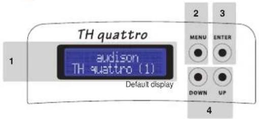
1 • TH quattro STATUS DISPLAY: it is the visual element of the ASC system, a back-lit two line 32 character LCD display; While working, it can relate all of the configuration parameters memorised by the amplifier during the installation, as well as the operational status of the amplifier.
The following pages address all the messages and information which from time to time the display can show. In case of protection intervention, the state of protection is permanently displayed, until the problem is resolved or until the amplifier is reset;
2 • MENU: this switch enables the ASC and shows the first available entry. Each time this switch is pushed while the amplifier is normally working, the ASC displays the first available entry, not the last you worked on. No matter which step of the management you are at, if you push the MENU button, you exit the ASC management and you are automatically taken back to the first display screen (Default display) without saving any changes.
Remark: No matter which step you are at of the management software, if you don't operate on the switches for 5 seconds, the ASC automatically goes back to the first display screen (Default display) without saving any changes.
3 • ENTER: this switch is to:
- confirm the selected entry, - store it in the memory, - move to the following menu entry. The ASC performs these three activities automatically. If you modify the menu entry you are working on and then you push "enter", the display will show:
then the display will show the next entry. The changes will only be made once ENTER is pushed.
4 • UP - DOWN: through these switches the user can browse through the entries available inside the different menus. According to the function you are checking, they allow you to modify your choice which, then, will have to be confirmed by pushing ENTER.
ASC - Amplifier Status Controller
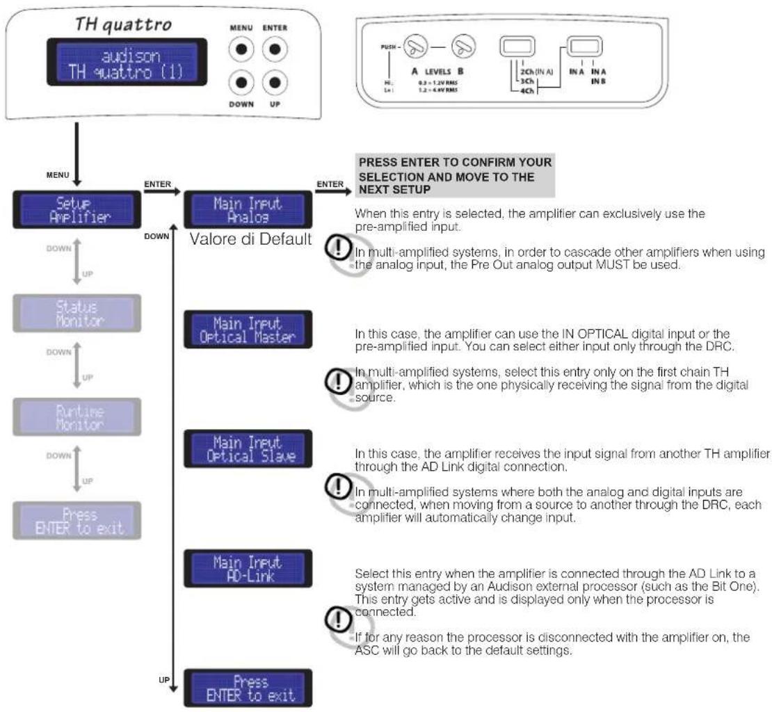
Setup Amplifier: Main Input
The first step to set the amplifier up is to select the main input the TH will use to get the signal. As soon as you turn the amplifier on, the PRE analog input is selected by default. By changing this entry the user can also take advantage of the other operational modes. From next time you turn the TH on, it will use the last selected entry.
If another input is used, the DRC is required. In that case, if for any reasons it is disconnected, all the setup settings and low level controls will reset back to the default settings, unless the DRC is re-connected, in which case they restore. (See page 35)
How to change: Main Input
How to adjust the volume control and input selector using a digital source
In the following pages you will find examples of how to connect the TH to a system driven by sources using the digital input. In order to use the TH IN OPTICAL digital input and therefore its D/A internal converter the DRC Digital Remote Control MUST be connected to the TH amplifier.
The DRC will perform the function of selecting the source by selecting between Analog Input and Optical Input, thus allowing the control of Main Volume, Subwoofer Volume, Balance and Fader.
If the last setup working conditions are no more valid, that is if you disconnect the DRC and you had changed the default conditions, the ASC will automatically go back to use the PRE Analog Input. In this case Fader and Balance will go back to central position, while general Volume and Sub Volume will go back to 0 dB (maximum value). The TH display will show the following information:
DRC not found: defaults loaded

natural_image
Gray circular icon with an exclamation mark symbol (no text or numbers)DRC Vol: 00.0dB = TH MAX Power Output
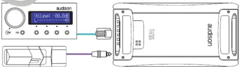
Warning:
When using the optical digital input you have to use the DRC as main volume control. If the DRC volume control is at 0 dB it equals to the amplifier undistorted maximum output power.
To check all the functions and the DRC connection, see pages 56
Front Panel
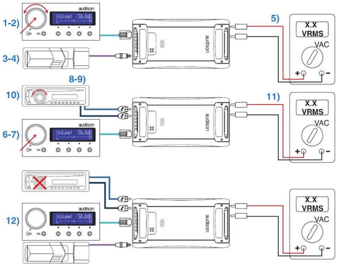
How to achieve same output volume level using an analog source (with its own volume control) and a digital source
Once you have adjusted the system, therefore once the amplifiers input sensitivity has been adjusted, you can adjust the digital source volume level so that when selecting the analog or the digital source no difference in sound is perceptible while listening. Once performed this adjustment, we would recommend that you use the DRC volume control as general volume control.
1) On the DRC select the source: Optical Input
2) On the DRC adjust volume until you can read -30.0 dB
3) Insert the Test CD provided with the amplifier into the source connected to the digital input
4) Select track # 05 (sinusoidal signal 1 kHz / 0 dB)
5) Using a multimeter (True RMS) measure the voltage on the speaker terminals
6) On the DRC select the source: Analog Input
7) Do not change the set volume (-30.0 dB)
8) Insert the Test CD provided with the amplifier into the source connected to the digital input
9) Select track # 05 (sinusoidal signal 1 kHz / 0 dB)
10) Adjust the volume of the source connected to the analog input until, using a multimeter (True RMS),
11) you measure the same voltage on the speaker terminals
12) Use the DRC as main volume control
Front Panel
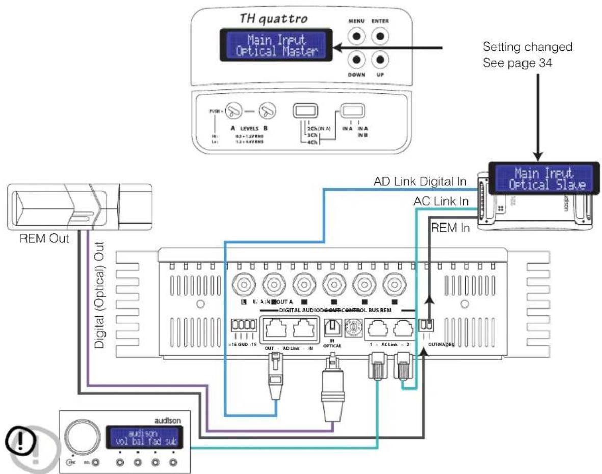
How to connect a source through the optical digital input in a system featuring more than one TH amplifier
TH configured in 4 / 3 / 2 Ch Mode
Input: Digital Optical S/P DIF
Pre Out: Digital AD Link
Power Output: 4 / 3 / 2 Ch
(Repeats the IN OPTICAL signal)
flowchart
graph TD
    A["TH quattro"] -->|MENU ENTER DOWN UP| B["Main Input Optical Master"]
    B --> C["Setting changed See page 34"]
    C --> D["Main Input Optical Slave"]
    D --> E["AD Link Digital In AC Link In REM In"]
    E --> F["Digital (Optical) Out"]
    F --> G["REM Out"]
    F --> H["audison vol bal fed sub"]
    H --> I["OUTINADRS"]
    I --> J["MODIFIER"]
    J --> K["OUTPUTAL AUDIO CONTROL BUS REM"]
    K --> L["MODIFIER OUT"]
    L --> M["MODIFIER IN"]
    M --> N["MODIFIER OUT"]
    N --> O["MODIFIER IN"]
    O --> P["MODIFIER OUT"]
    P --> Q["MODIFIER IN"]
    Q --> R["MODIFIER OUT"]
    R --> S["MODIFIER IN"]
    S --> T["MODIFIER OUT"]
In this case the DRC is REQUIRED to:
- Adjust the general volume
- Select the optical input
PRE OUT:
anyway available, see page 38
Front Panel
How to connect a source through an optical digital input in a system featuring other non-TH amplifiers
TH configured in 4 / 3 / 2 Ch Mode
Input: Digital Optical S/P DIF
Pre Out: Stereo Analog
Power Output: 4 / 3 / 2 Ch
(R and L Ch of Digital Input)
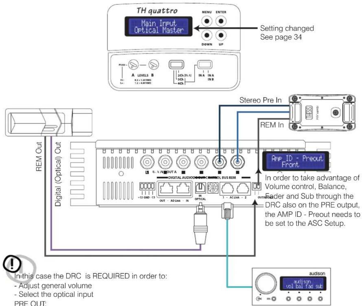
see page 44 to check how to manage it
Front Panel
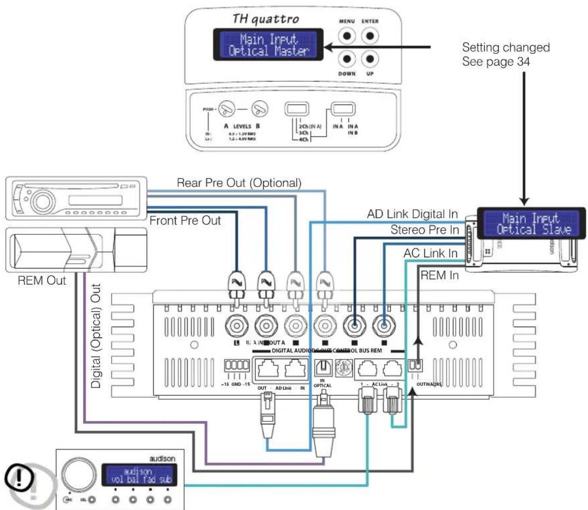
How to connect an analog and a digital source in a system featuring more than one TH amplifier
TH configured in 4 / 3 / 2 Ch Mode
Input: Analog/Digital Optical S/P DIF
Pre Out: Analog/Digital AD Link
Power Output: 4 / 3 / 2 Ch
flowchart
graph TD
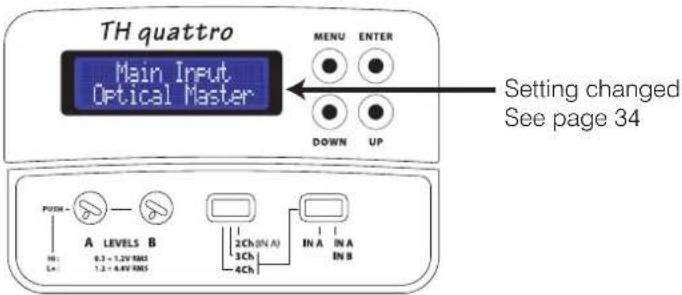
    A["TH quattro"] -->|MENU ENTER DOWN UP| B["Main Input Optical Master"]
    B --> C["Setting changed See page 34"]
    C --> D["Main Input Optical Slave"]
    D --> E["AD Link Digital In Stereo Pre In AC Link In REM In OUTINKADIRE"]
    E --> F["Digital Audio/UX Control Bus Rem"]
    F --> G["Digital (Optical) Out"]
    G --> H["Front Pre Out"]
    H --> I["Rear Pre Out (Optional)"]
    I --> J["Digital (Optical) Out"]
    J --> K["REM Out"]
    K --> L["audison vol bal fad sub"]
    L --> M["audison vol bal fad sub"]
In this case the DRC is REQUIRED to:
- Adjust general volume
- Select the optical input
PRE OUT:
anyway available, see page 40
Front Panel
How to connect an analog and a digital source in a system featuring other non-TH amplifiers
TH configured in 4 / 3 / 2 Ch Mode
Input: Analog/Digital Optical S/P DIF
Pre Out: Stereo Analog
Power Output: 4 / 3 / 2 Ch
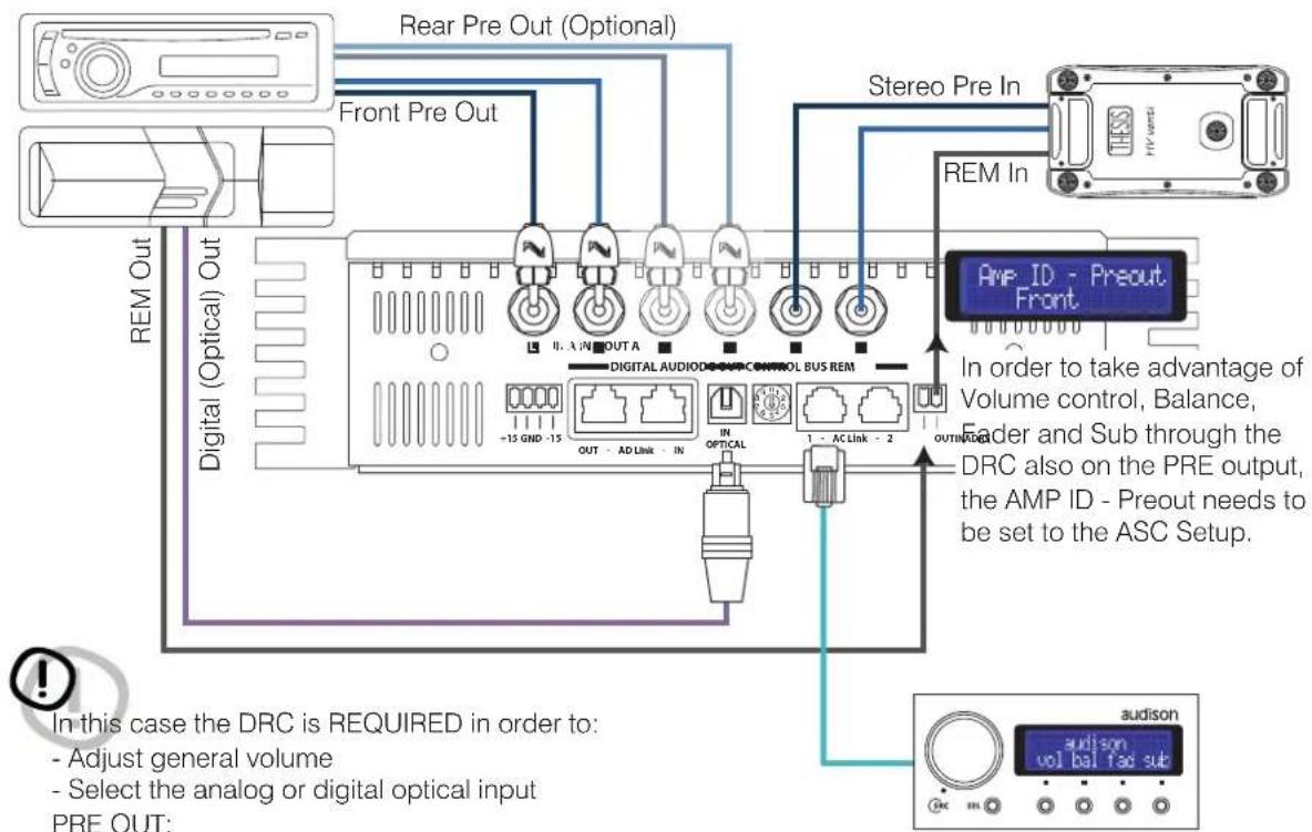
In this case the DRC is REQUIRED in order to:
- Adjust general volume
- Select the analog or digital optical input PRE OUT:
see page 44 to check how to manage it
ASC - Amplifier Status Controller
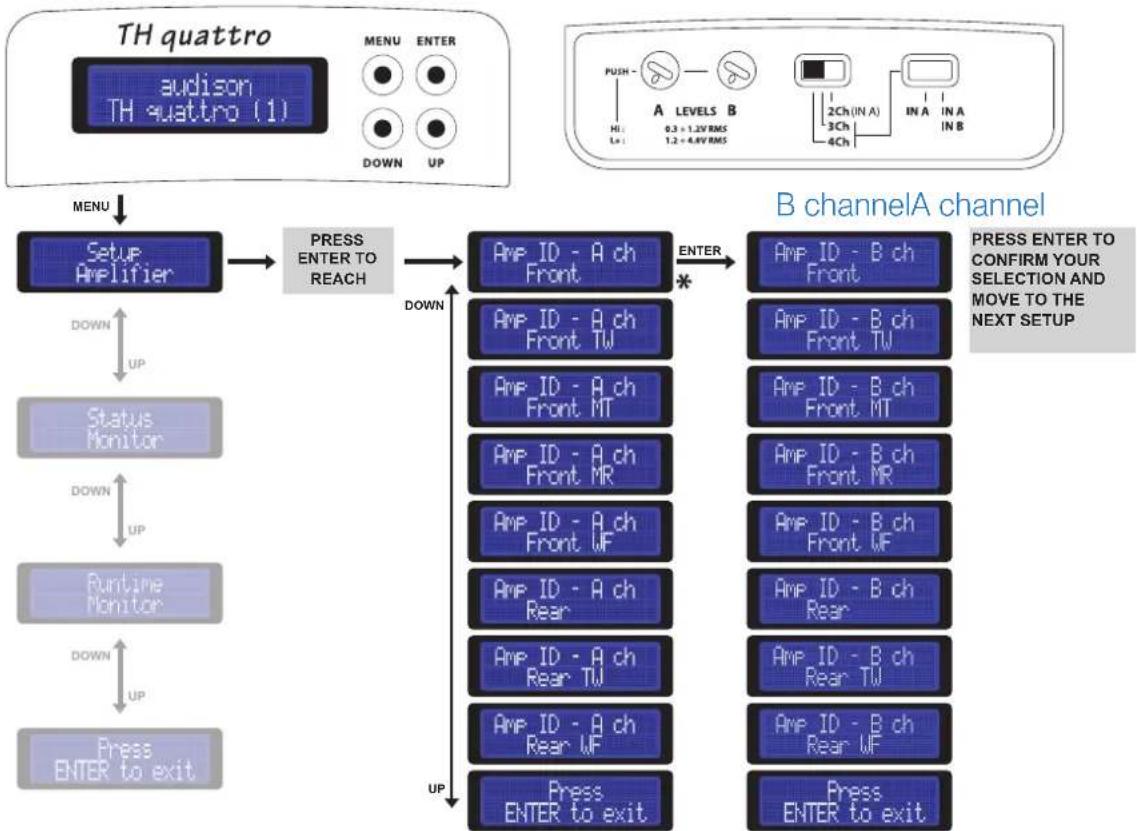
Setup Amplifier: Amp ID on 4 Ch Mode
AMP ID stands for Amplifier IDentification. The AMP ID is a way to identify the task the amplifier performs inside the system. The AMP ID does not affect the electric functioning and does not act on the amplifier electronic crossover. The AMP ID is fundamental to adjust Volume, Balance, Fader as well as Sub Volume when the DRC is connected. The ASC recognises the function the amplifier has been given through the ID. By acting on the DRC and adjusting Volume, Balance, Fader as well as Sub Volume, as a consequence also the signal to the amplifiers will be managed.
Example:
If the AMP ID-Front is assigned to the TH amplifier, by operating on the DRC its general volume, as well as the right/left balance, will change. Also, by setting the Fader on Rear you will hear the volume diminishing; however, no change will be perceived if you operate on the DRC Sub volume.
Vice versa, if the AMP ID – Subwoofer is assigned to the TH amplifier, by operating on the DRC its general volume, more specifically the Sub volume, will change; however, no change will be perceived if you operate on the right/left balance or moving the Fader.

In order to avoid errors, you should assign the ID according to the speakers connected to the amplifier.
flowchart
graph TD
    A["TH quattro"] --> B["Setup Amplifier"]
    B --> C["PRESS ENTER TO REACH"]
    C --> D["AMP ID - A ch Front"]
    D --> E["AMP ID - B ch Front"]
    D --> F["AMP ID - A ch Front TW"]
    D --> G["AMP ID - A ch Front MT"]
    D --> H["AMP ID - A ch Front MR"]
    D --> I["AMP ID - A ch Front WF"]
    D --> J["AMP ID - A ch Rear"]
    D --> K["AMP ID - A ch Rear TW"]
    D --> L["AMP ID - A ch Rear WF"]
    D --> M["Press ENTER to exit"]
    C --> N["DOWN UP"]
    N --> O["Status Monitor"]
    O --> P["DOWN UP"]
    P --> Q["Runtime Monitor"]
    Q --> R["DOWN UP"]
    R --> S["Press ENTER to exit"]
    style A fill:#f9f,stroke:#333
    style B fill:#ccf,stroke:#333
    style C fill:#cfc,stroke:#333
    style D fill:#fcc,stroke:#333
    style E fill:#cff,stroke:#333
    style F fill:#ffc,stroke:#333
    style G fill:#ffc,stroke:#333
    style H fill:#ffc,stroke:#333
    style I fill:#ffc,stroke:#333
    style J fill:#ffc,stroke:#333
    style K fill:#ffc,stroke:#333
    style L fill:#ffc,stroke:#333
    style M fill:#ffc,stroke:#333
* Default Entries
ASC - Amplifier Status Controller
Setup Amplifier: Amp ID on 3 Ch Mode
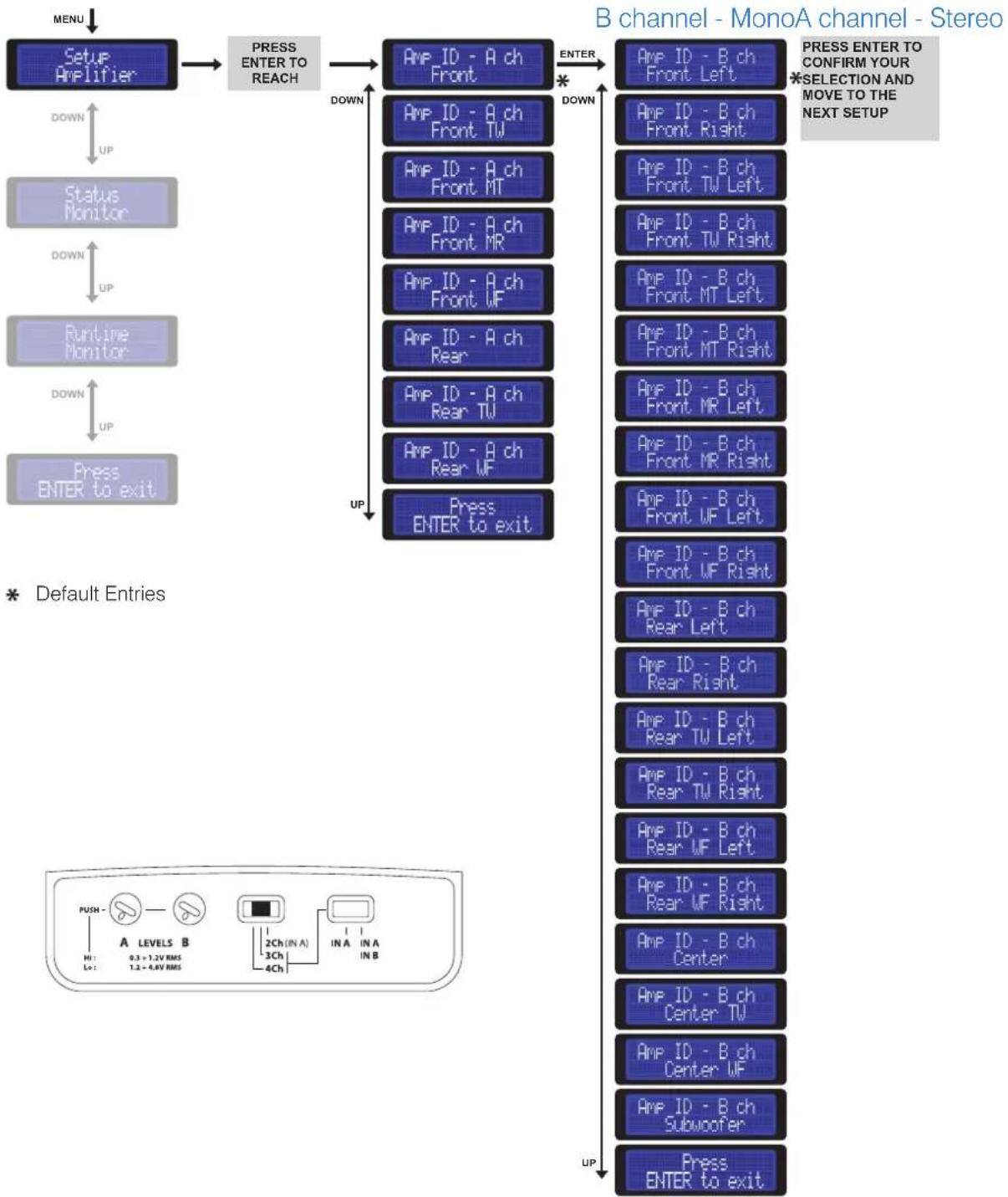
flowchart
graph TD
    A["MENU"] --> B["Setup Amplifier"]
    B --> C["PRESS ENTER TO REACH"]
    C --> D["AMP ID - A ch Front"]
    D --> E["AMP ID - B ch Front Left"]
    D --> F["AMP ID - B ch Front Right"]
    D --> G["AMP ID - B ch Front TW Left"]
    D --> H["AMP ID - B ch Front TW Right"]
    D --> I["AMP ID - B ch Front MT Left"]
    D --> J["AMP ID - B ch Front MT Right"]
    D --> K["AMP ID - B ch Front MR Left"]
    D --> L["AMP ID - B ch Front MR Right"]
    D --> M["AMP ID - B ch Front WF Left"]
    D --> N["Press ENTER to exit"]
    C --> O["DOWN UP"]
    O --> P["Status Monitor"]
    P --> Q["DOWN UP"]
    Q --> R["Runtime Monitor"]
    R --> S["DOWN UP"]
    S --> T["Press ENTER to exit"]

    U["* Default Entries"] --> V["B channel - MonoA channel - Stereo"]
    V --> W["PRESS ENTER TO CONFIRM YOUR *SELECTION AND MOVE TO THE NEXT SETUP"]

    V --> X["UP UP"]

    Y["PUSH - A LEVELS B 0.3 + 1.2V RMS 1.2 + 4.8V RMS"] --> Z["2Ch (IN A) 3Ch 4Ch IN A IN B"]
    Z --> AA["IN A IN B"]
ASC - Amplifier Status Controller
Setup Amplifier: Amp ID on 2 Ch Mode

In this configuration the TH quattro is like a Stereo amplifier. You can assign the AMP ID as a Stereo model.

flowchart
graph TD
    A["TH quattro"] --> B["audison TH quattro (1)"]
    B --> C["MENU"]
    C --> D["Setup Amplifier"]
    D --> E["PRESS ENTER TO REACH"]
    E --> F["A channel"]
    F --> G["AMP ID - A ch Front"]
    F --> H["AMP ID - A ch Front TW"]
    F --> I["AMP ID - A ch Front MT"]
    F --> J["AMP ID - A ch Front MR"]
    F --> K["AMP ID - A ch Front WF"]
    F --> L["AMP ID - A ch Rear"]
    F --> M["AMP ID - A ch Rear TW"]
    F --> N["AMP ID - A ch Rear WF"]
    F --> O["Press ENTER to exit"]
    D --> P["DOWN UP"]
    P --> Q["Status Monitor"]
    Q --> R["Down UP"]
    R --> S["Runtime Monitor"]
    S --> T["Down UP"]
    T --> U["Press ENTER to exit"]
    F --> V["* ENTER PRESS ENTER TO CONFIRM YOUR SELECTION AND MOVE TO THE NEXT SETUP"]
* Default Entries
ASC - Amplifier Status Controller
The AMP ID can also be assigned to the PRE OUT output. This function is extremely useful in case the TH amplifier is added to a pre-existing system featuring not only TH amplifiers or if you want to add to the TH system a non-TH amplifier. This way you can anyway know the non-TH amplifier function as well as adjust its volume. The AMP ID - Preout provides the ability to expand the system endlessly, keeping the low level parameters management functions through the DRC.
!
As the AMP ID – Preout does not operate on the electronic crossover, it does not put in any filters on the output signal! The signal on the PRE OUT output will always be exactly the same as the one on the selected input. In any case, 4 / 3 / 2 Ch Mode, the Amp ID-Preout will be able to drive a Stereo system.
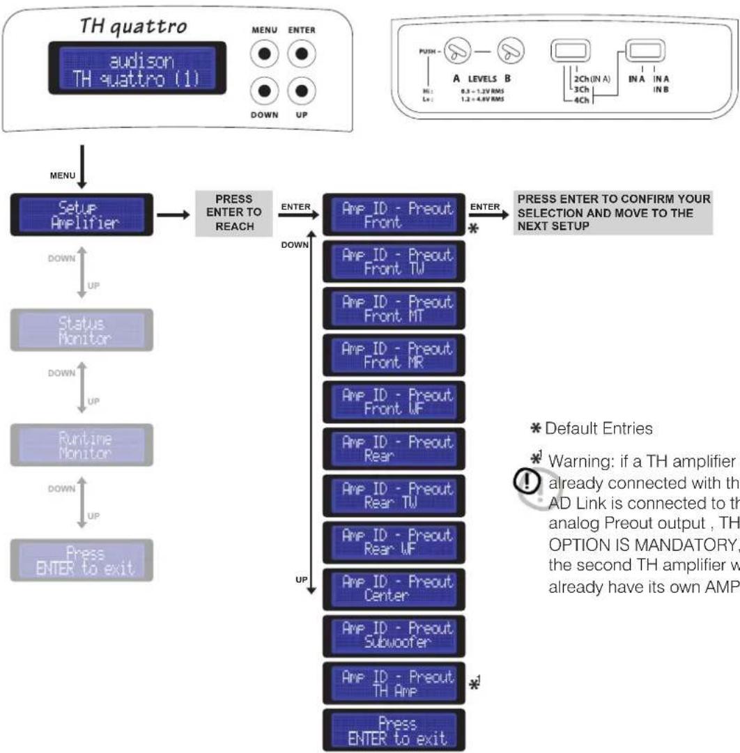
flowchart
graph TD
    A["TH quattro"] --> B["Setup Amplifier"]
    B --> C["Press ENTER TO REACH"]
    C --> D["AMP ID - Preout Front"]
    D --> E["ENTER *"]
    E --> F["PRESS ENTER TO CONFIRM YOUR SELECTION AND MOVE TO THE NEXT SETUP"]
    G["TH quattro (1)"] --> H["MENU"]
    H --> I["DOWN UP"]
    I --> J["Status Monitor"]
    J --> K["DOWN UP"]
    K --> L["Runtime Monitor"]
    L --> M["DOWN UP"]
    M --> N["Press ENTER to exit"]
    D --> O["Down UP"]
    O --> P["Amp ID - Preout Front TW"]
    P --> Q["Amp ID - Preout Front MT"]
    Q --> R["Amp ID - Preout Front MR"]
    R --> S["Amp ID - Preout Front UF"]
    S --> T["Amp ID - Preout Rear"]
    T --> U["Amp ID - Preout Rear TW"]
    U --> V["Amp ID - Preout Rear UF"]
    V --> W["Amp ID - Preout Center"]
    W --> X["Amp ID - Preout Subwoofer"]
    X --> Y["Amp ID - Preout TH Amp"]
    Y --> Z["Amp ENTER to exit"]
Front Panel
How to adjust the PRE OUT analog output
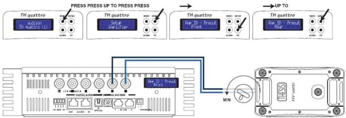
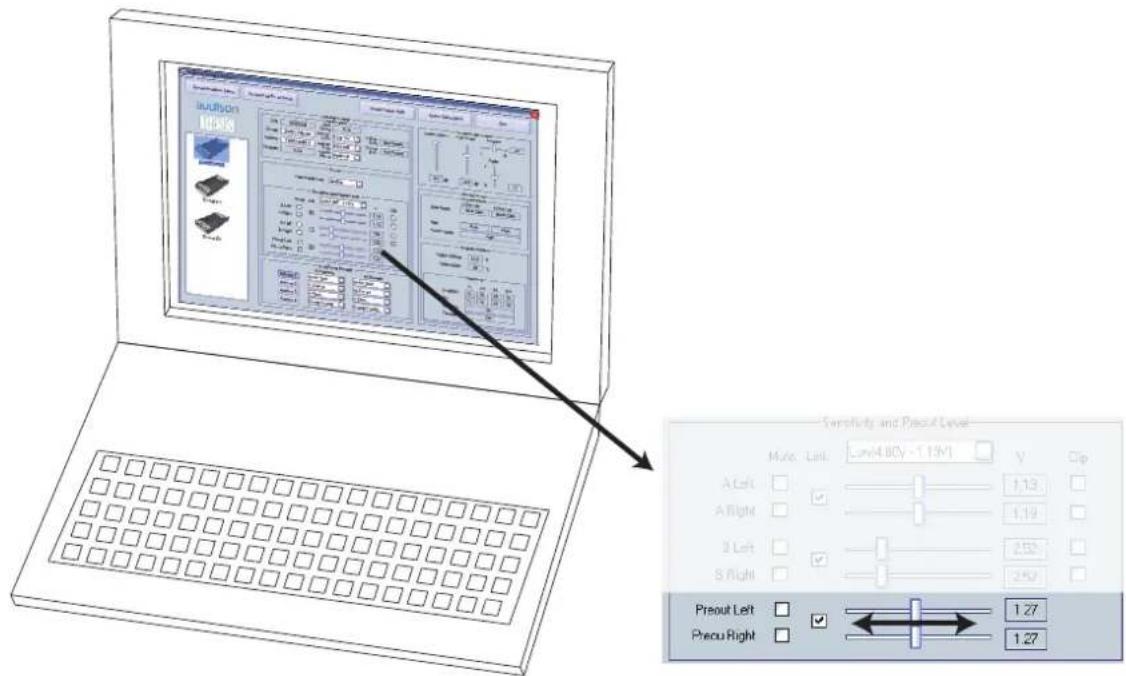
As already said, the AMP ID can also be assigned to the PRE OUT output, but not only to it. Through the AC Net software also the PRE OUT sensitivity can be adjusted to align the gain of the amplifier connected to that output, thus adapting sensitivity according to the system general volume increase and decrease.
The procedure to perform this operation is the following:
1- Connect the (non-TH) amplifier to the PRE output.
2- Assign the ID - Preout.
3- Set the non-TH amplifier sensitivity to the minimum.
4- Through the AC Net slider, increase the output sensitivity until you get the desired volume.
5- Should it not be enough, increase the non-TH amplifier input sensitivity
flowchart
graph TD
    A["TH quattro"] --> B["TH quattro (1)"]
    B --> C["TH quattro Setup Amplifier"]
    C --> D["TH quattro Amp ID - Freout Front"]
    D --> E["TH quattro Amp ID - Freout Rear"]
    E --> F["TH quattro UP TO PRESS PRESS"]
    F --> G["UP TO"]
    G --> H["MIN"]
    H --> I["TV/HV venti/"]

    subgraph PressPressUP
        B -->|MENI ENTER| B
        B -->|DOWN UP| B
    end

    subgraph PressPressUP
        C -->|MENI ENTER| C
        C -->|DOWN UP| C
    end

    subgraph UPTO
        D -->|MENI ENTER| D
        D -->|DOWN UP| D
    end

    subgraph DigitalBusControl
        I --> J["Digital Audio Control Bus Rem"]
        J --> K["HV Vent/ HV vent/"]
        K --> L["13.000 15"]
        L --> M["OUT - AC/HA - 2 OUT/RES"]
        M --> N["1 - AC/HA - 2 OUT/RES"]
        N --> O["13.000 15"]
        O --> P["OUT - AC/HA - 2 OUT/RES"]
        P --> Q["13.000 15"]
        Q --> R["OUT - AC/HA - 2 OUT/RES"]
        R --> S["13.000 15"]
        S --> T["OUT - AC/HA - 2 OUT/RES"]
        T --> U["13.000 15"]
        U --> V["OUT - AC/HA - 2 OUT/RES"]
        V --> W["13.000 15"]
        W --> X["OUT - AC/HA - 2 OUT/RES"]
        X --> Y["13.000 15"]
        Y --> Z["OUT - AC/HA - 2 OUT/RES"]
        Z --> AA["13.000 15"]
        AA --> AB["OUT - AC/HA - 2 OUT/RES"]
        AB --> AC["13.000 15"]
        AC --> AD["OUT - AC/HA - 2 OUT/RES"]
        AD --> AE["13.000 15"]
        AE --> AF["OUT - AC/HA - 2 OUT/RES"]
        AF --> AG["13.000 15"]
        AG --> AH["OUT - AC/HA - 2 OUT/RES"]
        AH --> AI["13.000 15"]
        AI --> AJ["OUT - AC/HA - 2 OUT/RES"]
        AJ --> AK["13.000 15"]
        AK --> AL["OUT - AC/HA - 2 OUT/RES"]
        AL --> AM["13.000 15"]
        AM --> AN["OUT - AC/HA - 2 OUT/RES"]
        AN --> AO["13.000 15"]
        AO --> AP["OUT - AC/HA - 2 OUT/RES"]
        AP --> AQ["13.000 15"]
        AQ --> AR["OUT - AC/HA - 2 OUT/RES"]
        AR --> AS["13.000 15"]
        AS --> AT["OUT - AC/HA - 2 OUT/RES"]
        AT --> AU["13.000 15"]
        AU --> AV["OUT - AC/HA - 2 OUT/RES"]
        AV --> AW["13.000 15"]
        AW --> AX["OUT - AC/HA - 2 OUT/RES"]
        AX --> AY["13.000 15"]
        AY --> AZ["OUT - AC/HA - 2 OUT/RES"]
        AZ --> BA["13.000 15"]
        BA --> BB["OUT - AC/HA - 2 OUT/RES"]
        BB --> BC["13.000 15"]
        BC --> BD["OUT - AC/HA - 2 OUT/RES"]
        BD --> BE["13.000 15"]
        BE --> BF["OUT - AC/HA - 2 OUT/RES"]
        BF --> BG["13.000 15"]
        BG --> BH["OUT - AC/HA - 2 OUT/RES"]
        BH --> BI["13.000 15"]
        BI --> BJ["OUT - AC/HA - 2 OUT/RES"]
        BJ --> BK["13.000 15"]
        BK --> BL["OUT - AC/HA - 2 OUT/RES"]
        BL --> BM["13.000 15"]
        BM --> BN["OUT - AC/HA - 2 OUT/RES"]
        BN --> BO["13.000 15"]
        BO --> BP["OUT - AC/HA - 2 OUT/RES"]
        BP --> BQ["13.000 15"]
        BQ --> BR["OUT - AC/HA - 2 OUT/RES"]
        BR --> BS["13.000 15"]
        BS --> BT["OUT - AC/HA - 2 OUT/RES"]
        BT --> BU["13.000 15"]
        BU --> BV["OUT - AC/HA - 2 OUT/RES"]
        BV --> BW["13.000 15"]
        BW --> BX["OUT - AC/HA - 2 OUT/RES"]
        BX --> BY["13.000 15"]
        BY --> BZ["OUT - AC/HA - 2 OUT/RES"]
        BZ --> CA["13.000 15"]
        CA --> CB["OUT - AC/HA - 2 OUT/RES"]
        CB --> CC["13.000 15"]
        CC --> CD["OUT - AC/HA - 2 OUT/RES"]
        CD --> CE["13.000 15"]
        CE --> CF["OUT - AC/HA - 2 OUT/RES"]
        CF --> CG["13.000 15"]
        CG --> CH["OUT - AC/HA - 2 OUT/RES"]
        CH --> CI["13.000 15"]
        CI --> CJ["OUT - AC/HA - 2 OUT/RES"]
        CJ --> CK["13.000 15"]
ASC - Amplifier Status Controller
Setup Amplifier : X-Over Slope of bridged channels (B) with TH quattro in 3 Ch mode
When the amplifier is set in 3 Ch Mode, you can choose the crossover filter slope of the B (bridged) channels.
Select 1-12 dB/oct: in this case, the Low-pass slope switch on the TH-MXR module will not be active.
Select 2-24 dB/oct: when this option is selected, the Low-pass slope switch on the TH-MXR module will anyway be active, thus providing the ability to mechanically choosing between 12 and 24 dB/oct.
For further information see page 23 ÷ 27
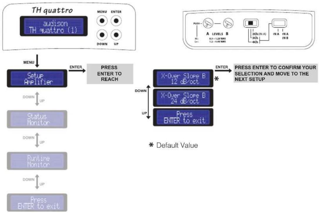
flowchart
graph TD
    A["TH quattro"] --> B["audison TH quattro (1)"]
    B --> C["MENU"]
    C --> D["Setup Amplifier"]
    D --> E["ENTER"]
    E --> F["PRESS ENTER TO REACH"]
    F --> G["X-Over Slope B 12 dB/oct"]
    F --> H["X-Over Slope B 24 dB/oct"]
    F --> I["Press ENTER to exit"]
    G --> J["* Default Value"]
    H --> J
    I --> J
    J --> K["PRESS ENTER TO CONFIRM YOUR SELECTION AND MOVE TO THE NEXT SETUP"]
TH quattro in 2 Ch mode

When the amplifier is set in 2 Ch Mode, crossover filter slope is always 12 dB/oct.
ASC - Amplifier Status Controller DUAL POWER & BIAS CONTROL
A revolutionary function called Dual Power was introduced for the first time in the HV venti.
Controlling the amplifier's output power configuration, this function allowed the predetermination of the amplifiers output power and of the grade of the outputs operational class. The digital interface enables expedient intervention by the user, setting up the amplifier's operational modes by operating on the power and bias current settings, all in real-time. In any case the result is a clear "sound customisation".
In this Setup section you can set the amplifier operational mode.
There are four possible presets:
Class A: to intensify the musical performance; you can not expect the amplifier to drive loads under 4 Ω under these conditions;
Hi-AB Class: it is the default mode, combining the characteristics of high class functioning, great capability of driving difficult loads and high power.
Hi-Current: Pure power, on any loads
Energy Saving: it sets the power emission to the minimum, allowing musical enjoyment for extended periods of time with the vehicles engine off.

When changing mode, you have to wait a few seconds to perceive the acoustic variations. The Dual Power is absolutely independent from the other settings selections. It will work both in Mono and in Stereo configurations, both with and without the crossover, both connecting a subwoofer and a tweeter to it. So we recommend you pay attention to select a functioning mode accepting the impedance load you applied to the amplifier. Check the following page for comparative charts with reference values.
Setup Amplifier: DUAL POWER Settings
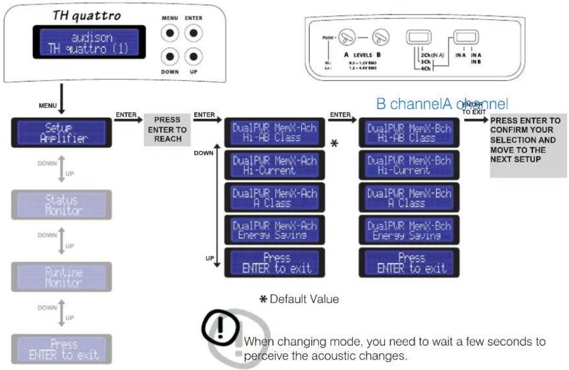
flowchart
graph TD
    A["TH quattro"] --> B["TH quattro (1)"]
    B --> C["MENU"]
    C --> D["Setup Amplifier"]
    D --> E["ENTER"]
    E --> F["PRESS ENTER TO REACH"]
    F --> G["ENTER"]
    G --> H["DualPUR MemX-Ach Hi-AB Class"]
    G --> I["DualPUR MemX-Ach Hi-Current"]
    G --> J["DualPUR MemX-Ach A Class"]
    G --> K["DualPUR MemX-Ach Energy Saving"]
    G --> L["Press ENTER to exit"]
    H --> M["*"]
    I --> M
    J --> M
    K --> M
    L --> M
    M --> N["DUALPUR MemX-Bch Hi-AB Class"]
    M --> O["DUALPUR MemX-Bch Hi-Current"]
    M --> P["DUALPUR MemX-Bch A Class"]
    M --> Q["DUALPUR MemX-Bch Energy Saving"]
    M --> R["Press ENTER to exit"]
    N --> S["B channelA channel"]
    O --> S
    P --> S
    Q --> S
    R --> S
    S --> T["ENTER TO EXIT"]
    T --> U["PRESS ENTER TO CONFIRM YOUR SELECTION AND MOVE TO THE NEXT SETUP"]
    V[" press ENTER to exit "]
    W[" default Value "]
    X["When changing mode, you need to wait a few seconds to perceive the acoustic changes. "]
ASC - Amplifier Status Controller
DUAL POWER Values
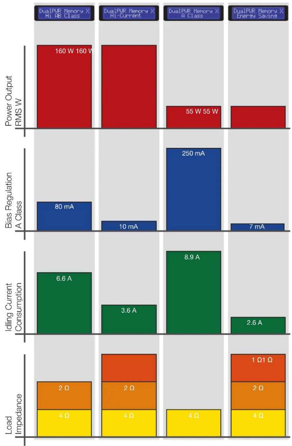
bar_stacked
| Category | Power Output RMS W | Bias Regulation A Class | Idling Current Consumption | Load Impedance | | :--- | :--- | :--- | :--- | :--- | | DualPUR Memory X Hi AB Class | 160 W 160 W | 80 mA | 6.6 A | 2 Ω | | DualPUR Memory X Hi-Current | 160 W 160 W | 10 mA | 3.6 A | 2 Ω | | DualPUR Memory X A Class | 55 W 55 W | 250 mA | 8.9 A | 4 Ω | | DualPUR Memory X Energy Saving | 55 W 55 W | 7 mA | 2.6 A | 4 Ω | The chart displays a stacked bar format with each bar representing a different component of the total power output. The labels above the bars indicate the specific components for each category.ASC - Amplifier Status Controller
Setup Amplifier: DUAL POWER Settings
How to change presets on the Memory (DRC required)
The TH quattro can be set with an operational mode for A Channels and an operational mode for B Channels. Using A Class or Energy Saving mode, these configurations will be automatically set on both channels. See the following chart:
| 1 | 2 | 3 | 4 | 5 | 6 | |
| Channels A | H-AB Class | Hi-Current | Hi-AB Class | Hi-Current | A Class | En.Saving |
| Channels B | H-AB Class | Hi-Current | Hi-Current | Hi-AB Class | A Class | En.Saving |
The DRC can manage four customisable memories.
1- Default: In standard configuration, without making any changes, if memory 1 is recalled from the DRC, all the TH amplifiers connected to the system will be working in Hi-AB Class mode (as it is the default setting), while selecting memory 2 they will be workin in Hi-Current mode and so on.
2- Customizing: by acting on both the DRC memories and the ASC control panel of the amplifier, you can create custom setups. For instance, if you want the TH amplifiers to anyway work in A-Class mode, you will have to act on the setup as follows:
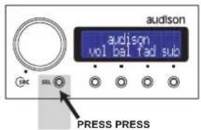
- Select memory 1 on the DRC by pressing first SEL and then 1
- Select the A-Class preset on the ASC by accessing to its corresponding setup
- Repeat this operation for each DRC memory
- Repeat this operation for each TH present in the system
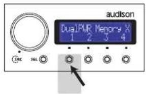

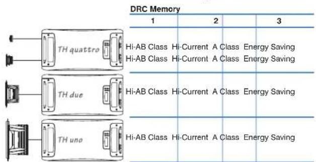
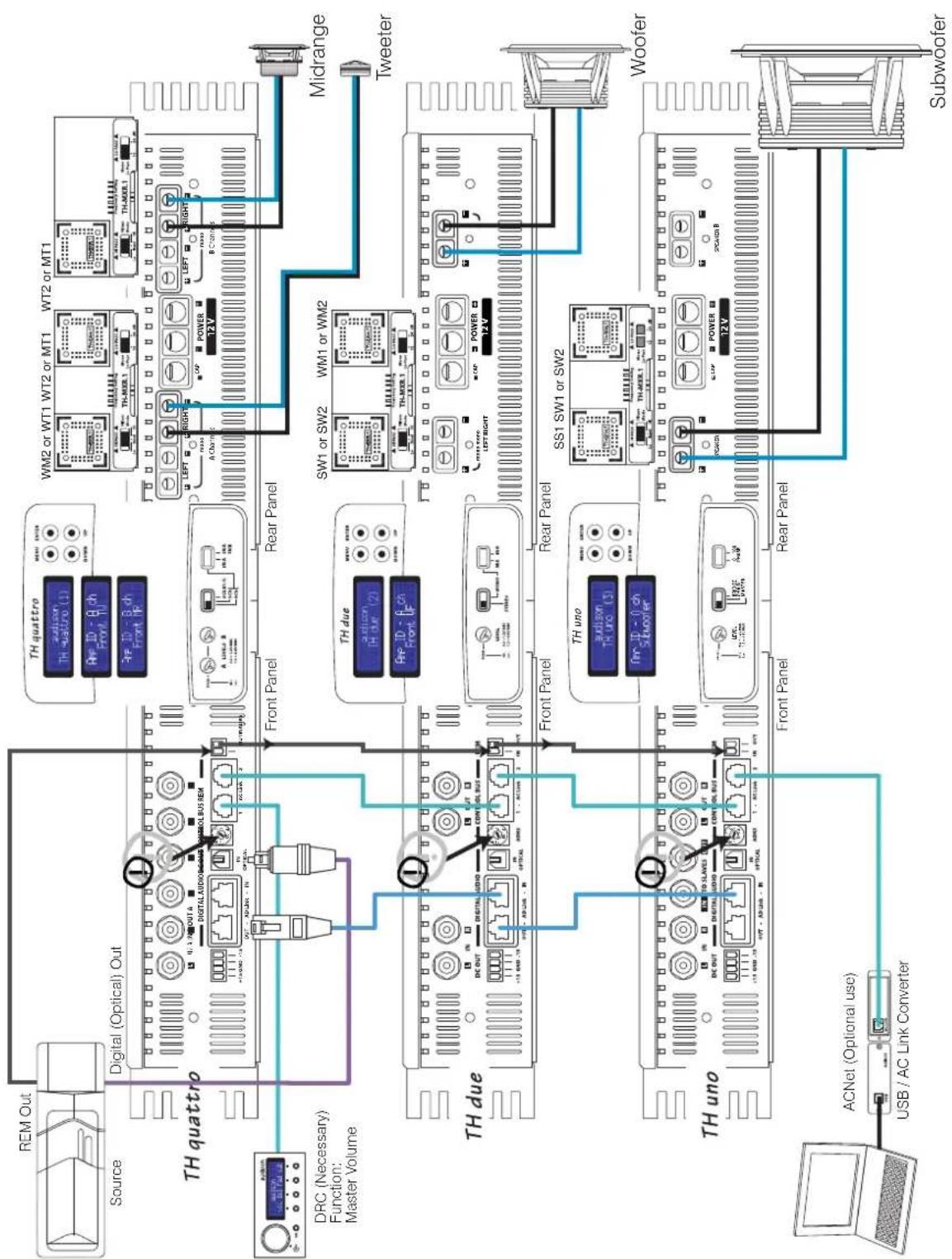
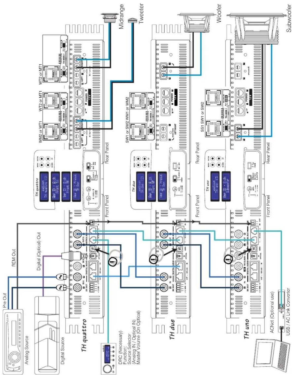
Example: In a three-way + Sub system, multi-amplified with TH quattro on TW and MID, TH due on WF and TH uno on SUB, in default setting if you recall memory 1 all of the TH's would work in Hi-AB Class mode. It is possible to create custom memories, see for instance the example below, to store in memory 1 a system especially designed to ensure top quality for each way or to store in memory 2 a system especially designed for the best power/quality ratio, to store in memory 3 a system set to obtain maximum quality and in memory 4 a system best optimizing the current consumption.
Default configuration → Modified configuration
| 4 | 1 | 2 | 3 |
| A Class Hi-AB Class A Class Energy SavingA Class Hi-Current A Class Energy Saving | |||
| Hi-AB Class Hi-Current A Class Energy Saving | |||
| Hi-Current Hi-Current A Class Energy Saving | |||
4
Example: Three Way+ multi-amplified Sub, TH amplifiers Digital Input
Example: Three Way + multi-amplified Sub, TH amplifiers Analog + Digital Input
flowchart
graph TD
    A["Analog Source"] --> B["Pre Out"]
    B --> C["REM Out"]
    C --> D["Digital (Optical) Out"]
    D --> E["TH quattro"]
    E --> F["Front Panel"]
    F --> G["Rear Panel"]
    G --> H["Midrange"]
    H --> I["Tweeter"]
    I --> J["Woofer"]
    J --> K["Subwoofer"]
    K --> L["ACNet (Optional use)"]
    L --> M["USB / AC Link Converter"]
    M --> N["TH uno"]
    N --> O["Front Panel"]
    O --> P["Rear Panel"]
    P --> Q["SS1 SW1 or SW2"]
    Q --> R["Front Panel"]
    R --> S["Rear Panel"]
    S --> T["TH uno"]
    T --> U["Front Panel"]
    U --> V["Rear Panel"]
    V --> W["SW1 or SW2 WM1 or WM2"]
    W --> X["Front Panel"]
    X --> Y["Rear Panel"]
    Y --> Z["TH due"]
    Z --> AA["Front Panel"]
    AA --> AB["Rear Panel"]
    AB --> AC["SW1 or SW2 WM1 or WM2"]
    AC --> AD["Front Panel"]
    AD --> AE["Rear Panel"]
    AE --> AF["TH due"]
    AF --> AG["Front Panel"]
    AG --> AH["Rear Panel"]
    AH --> AI["SW1 or SW2 WM1 or SW2"]
    AI --> AJ["Front Panel"]
    AJ --> AK["Rear Panel"]
Example: Three Way + Sub, multiamplified with and without TH amplifiers. Analog + Digital Input
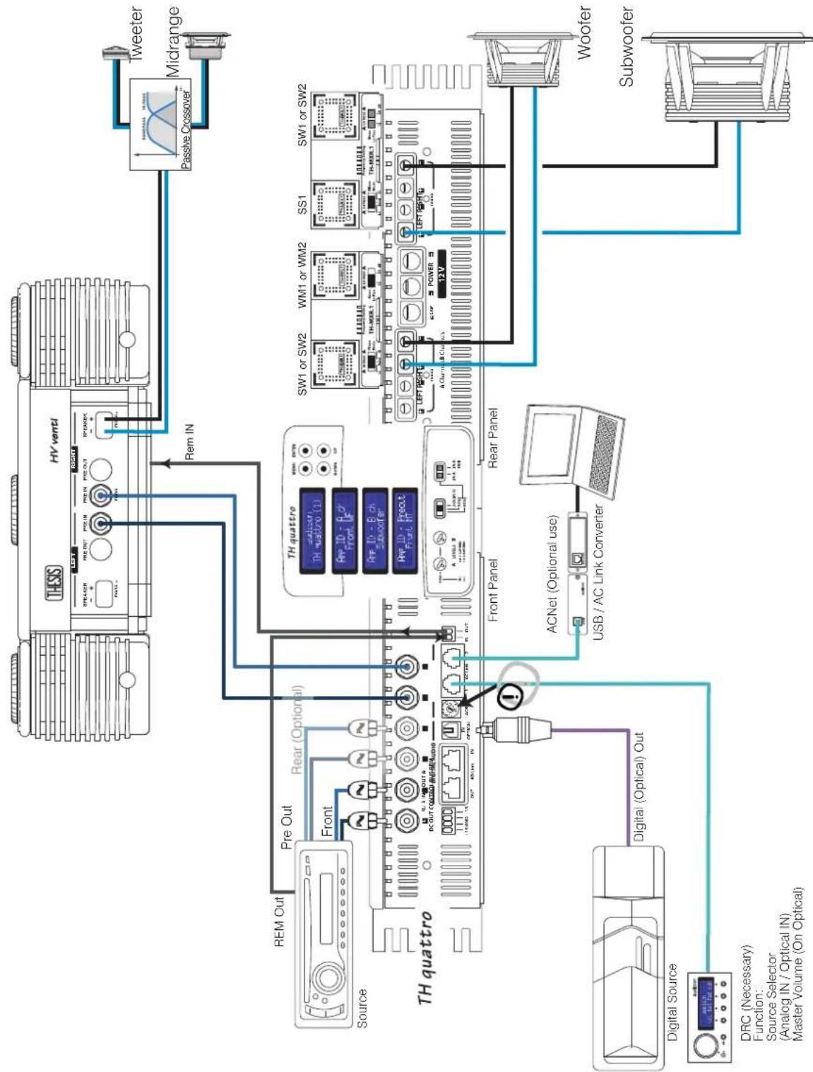
flowchart
graph TD
    A["TH quattro"] -->|Pre Out| B["TH venti"]
    A -->|Front| C["TH quattro (1)"]
    A -->|Rem Out| D["TH quattro (2)"]
    A -->|Rem In| E["Tweeter Midrange"]
    A -->|Rear (Optional)| F["ACNet (Optional use)"]
    A -->|Digital (Optical) Out| G["Digital Source"]
    A -->|Front Panel| H["ACNet (Optional use)"]
    A -->|Rear Panel| I["ACNet (Optional use)"]
    A -->|Rem In| J["Woofer Subwoofer"]
    A -->|Rem Out| K["Power Line 12V"]
    A --> L["Power Line 12V"]
    A --> M["Power Line 12V"]
    A --> N["Power Line 12V"]
    A --> O["Power Line 12V"]
    A --> P["Power Line 12V"]
    A --> Q["Power Line 12V"]
    A --> R["Power Line 12V"]
    A --> S["Power Line 12V"]
    A --> T["Power Line 12V"]
    A --> U["Power Line 12V"]
    A --> V["Power Line 12V"]
    A --> W["Power Line 12V"]
    A --> X["Power Line 12V"]
    A --> Y["Power Line 12V"]
    A --> Z["Power Line 12V"]
    A --> AA["Power Line 12V"]
    A --> AB["Power Line 12V"]
    A --> AC["Power Line 12V"]
    A --> AD["Power Line 12V"]
    A --> AE["Power Line 12V"]
    A --> AF["Power Line 12V"]
    A --> AG["Power Line 12V"]
    A --> AH["Power Line 12V"]
    A --> AI["Power Line 12V"]
    A --> AJ["Power Line 12V"]
    A --> AK["Power Line 12V"]
    A --> AL["Power Line 12V"]
    A --> AM["Power Line 12V"]
    A --> AN["Power Line 12V"]
    A --> AO["Power Line 12V"]
    A --> AP["Power Line 12V"]
    A --> AQ["Power Line 12V"]
    A --> AR["Power Line 12V"]
    A --> AS["Power Line 12V"]
    A --> AT["Power Line 12V"]
    A --> AU["Power Line 12V"]
    A --> AV["Power Line 12V"]
    A --> AW["Power Line 12V"]
    A --> AX["Power Line 12V"]
    A --> AY["Power Line 12V"]
    A --> AZ["Power Line 12V"]
ASC - Amplifier Status Controller Status Monitor
This feature of the ASC provides the ability to monitor the amplifier working status by moving through the different entries the data regarding the working TH amplifier will show. When displaying a value, if you do not act on any of the buttons for 5 seconds, the ASC automatically goes back to the default display screen.
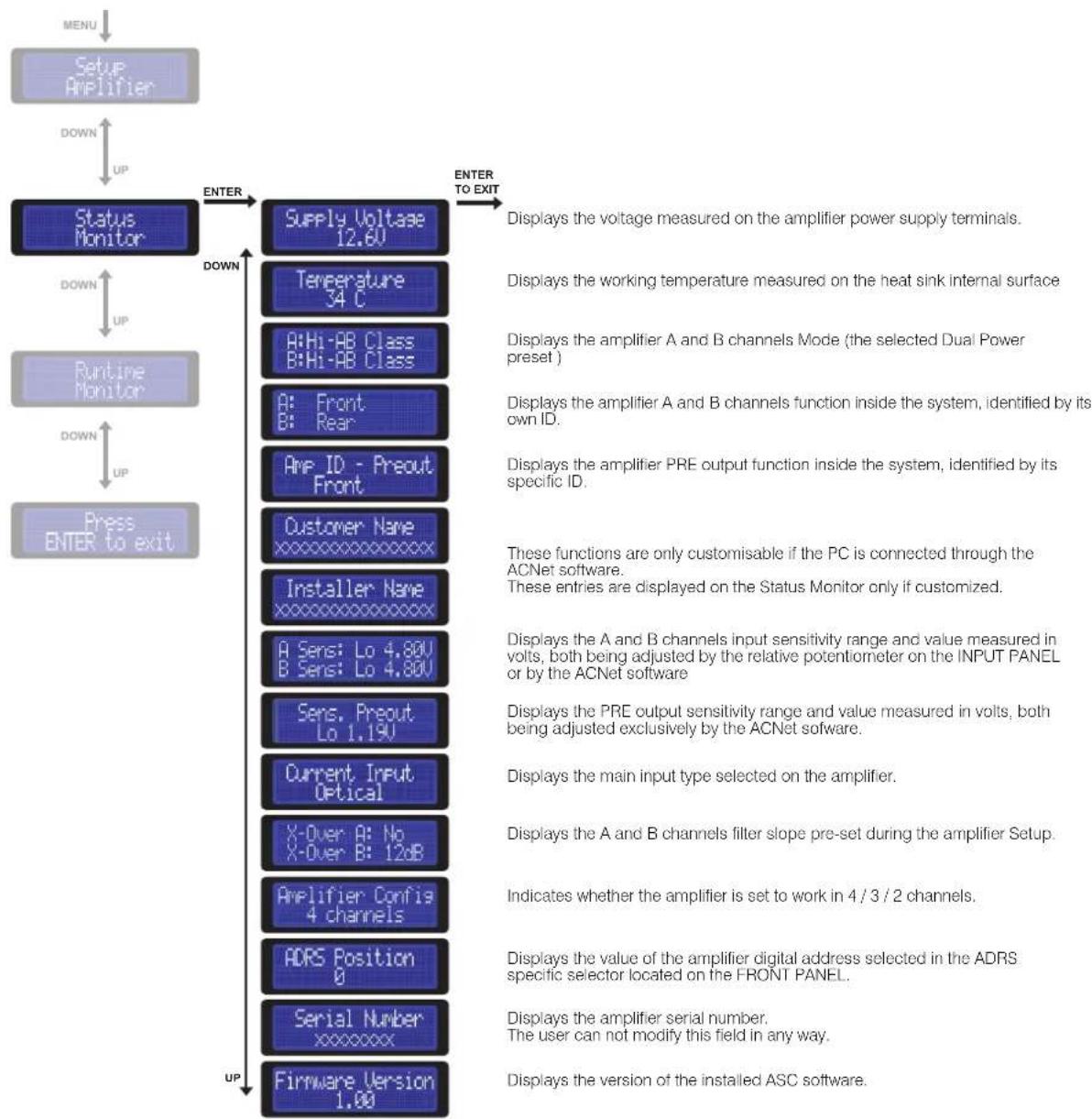
flowchart
graph TD
    A["MENU"] --> B["Setup Amplifier"]
    B --> C["DOWN UP"]
    C --> D["Status Monitor"]
    D --> E["DOWN UP"]
    E --> F["Runtime Monitor"]
    F --> G["DOWN UP"]
    G --> H["Press ENTER to exit"]

    D --> I["ENTER"]
    I --> J["Supply Voltage 12.6V"]
    J --> K["Temperature 34°C"]
    K --> L["A: Hi-AB Class B: Hi-AB Class"]
    L --> M["A: Front B: Rear"]
    M --> N["AMP ID - Preout Front"]
    N --> O["Customer Name xxxxxxxxxxxxxx"]
    O --> P["Installer Name xxxxxxxxxxxxxx"]
    P --> Q["A Sens: Lo 4.80V B Sens: Lo 4.80V"]
    Q --> R["Sens, Preout Lo 1.19V"]
    R --> S["Current Input Optical"]
    S --> T["X-Over A: No X-Over B: 12dB"]
    T --> U["Amplifier Confis 4 channels"]
    U --> V["ADRS Position 0"]
    V --> W["Serial Number xxxxxxxx"]
    W --> X["Firmware Version 1.00"]

    J --> Y["ENTER TO EXIT"]
    Y --> Z["Displays the voltage measured on the amplifier power supply terminals."]
    Y --> AA["Displays the working temperature measured on the heat sink internal surface"]
    Y --> AB["Displays the amplifier A and B channels Mode (the selected Dual Power preset)"]
    Y --> AC["Displays the amplifier A and B channels function inside the system, identified by its own ID."]
    Y --> AD["Displays the amplifier PRE output function inside the system, identified by its specific ID."]
    Y --> AE["These functions are only customisable if the PC is connected through the ACNet software. These entries are displayed on the Status Monitor only if customized."]
    Y --> AF["Displays the A and B channels input sensitivity range and value measured in volts, both being adjusted by the relative potentiometer on the INPUT PANEL or by the ACNet software"]
    Y --> AG["Displays the PRE output sensitivity range and value measured in volts, both being adjusted exclusively by the ACNet software."]
    Y --> AH["Displays the main input type selected on the amplifier."]
    Y --> AI["Displays the A and B channels filter slope pre-set during the amplifier Setup."]
    Y --> AJ["Indicates whether the amplifier is set to work in 4/3/2 channels."]
    Y --> AK["Displays the value of the amplifier digital address selected in the ADRS specific selector located on the FRONT PANEL."]
    Y --> AL["Displays the amplifier serial number. The user can not modify this field in any way."]
    Y --> AM["Displays the version of the installed ASC software."]
ASC - Amplifier Status Controller
Runtime Monitor
This function of the ASC provides the ability to alternately show on the amplifier display the information on its operational status. Through this setup you can select the fields you want to be visible when the amplifier is on. For each field you can select YES to have the entry show on the display. If all NO are selected, the display will always show the default display screen. You will only have to select even just one entry to see it appear alternately on the display while the amplifier is working. By default all the fields are pre-set on NO.
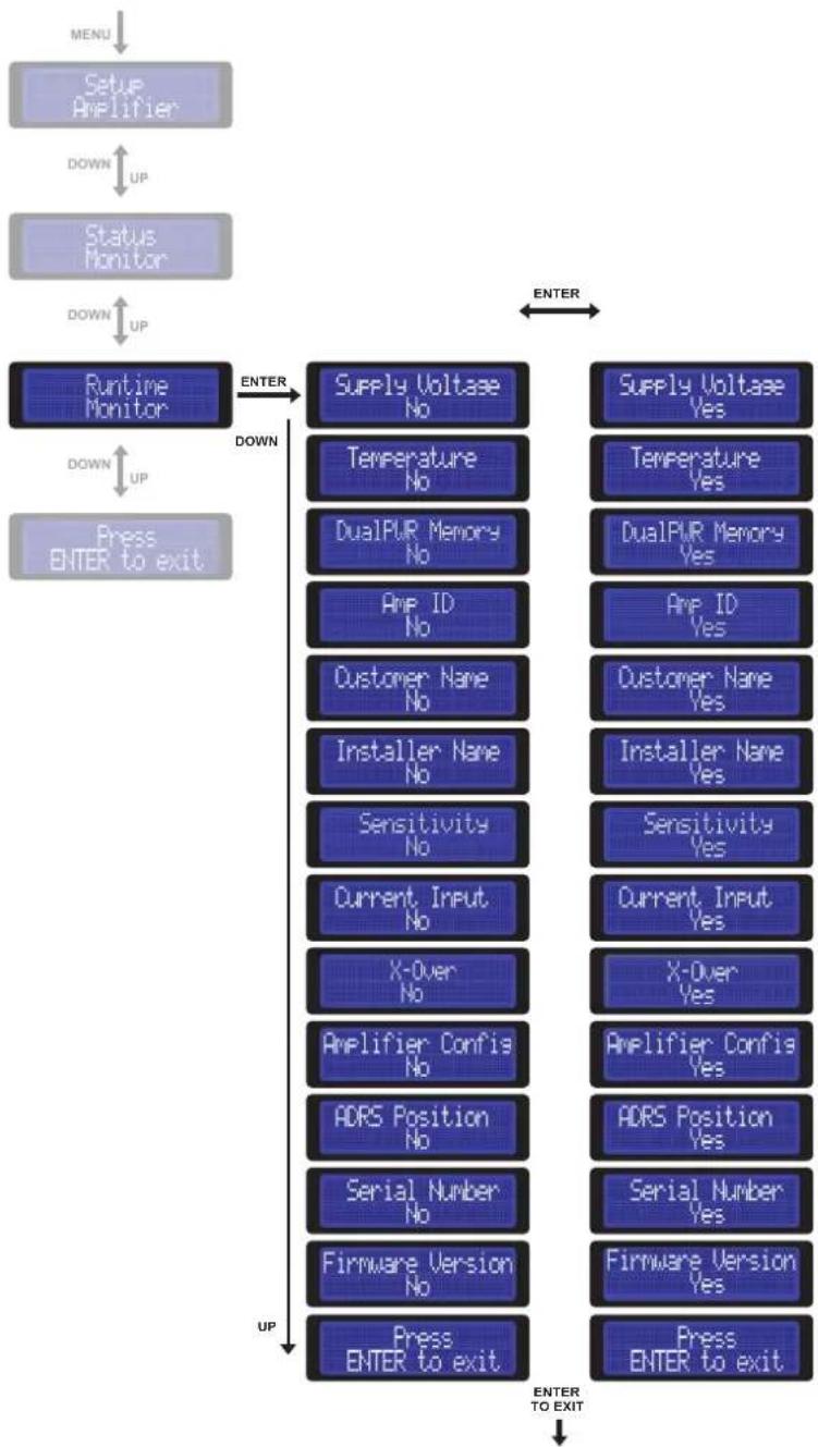
flowchart
graph TD
    A["MENU"] --> B["Setup Amplifier"]
    B --> C["DOWN UP"]
    C --> D["Status Monitor"]
    D --> E["DOWN UP"]
    E --> F["Runtime Monitor"]
    F --> G["DOWN UP"]
    G --> H["Press ENTER to exit"]

    I["ENTER"] --> J["Supply Voltage No"]
    I --> K["Temperature No"]
    I --> L["DualPUR Memory No"]
    I --> M["Amp ID No"]
    I --> N["Customer Name No"]
    I --> O["Installer Name No"]
    I --> P["Sensitivity No"]
    I --> Q["Current Input No"]
    I --> R["X-Over No"]
    I --> S["Ampifier Confis No"]
    I --> T["ADRS Position No"]
    I --> U["Serial Number No"]
    I --> V["Firmware Version No"]
    I --> W["Press ENTER to exit"]

    X["ENTER"] --> Y["Supply Voltage Yes"]
    X --> Z["Temperature Yes"]
    X --> AA["DualPUR Memory Yes"]
    X --> AB["Amp ID Yes"]
    X --> AC["Customer Name Yes"]
    X --> AD["Installer Name Yes"]
    X --> AE["Sensitivity Yes"]
    X --> AF["Current Input Yes"]
    X --> AG["X-Over Yes"]
    X --> AH["Ampifier Confis Yes"]
    X --> AI["ADRS Position Yes"]
    X --> AJ["Serial Number Yes"]
    X --> AK["Firmware Version Yes"]
    X --> AL["Press ENTER to exit"]

    M --> J
    N --> K
    O --> L
    P --> M
    Q --> N
    R --> O
    S --> P
    T --> Q
    U --> S
    V --> T
    W --> U
    X --> Y
    Y --> Z
    Z --> AA
    AA --> AB
    AB --> AC
    AC --> AD
    AD --> AE
ASC - Amplifier Status Controller
Info and Alert sentences
What the TH is doing
1 Amp in default
What the display is showing
What it means
DRC not found: defaults loaded
The previously found connection with DRC has been lost. This information is also displayed when the amplifier is on and the DRC gets disconnected. Volume goes back to 0 dB (the set sensitivity is not modified), Balance and Fader are set back to their centre position (0). The Sub volume is set back to 0 dB. The ANALOG input is automatically selected.
2 Amp in muting
Set 4ch or setup amplifier
Set 3ch or setup amplifier
Set 2ch or setup amplifier
4/3/2 Ch switch position is different from the original position acquired during the Amplifier Setup. You have to access to the ASC and at least set the AMP ID.
3 Amp off
Protection Service A-L
Protection Service A-R
Left or right A channel general protection. The amplifier will try to restart 5 times. Contact Audison Technical Support.
4 Amp off
Protection Service B-L
Protection Service B-R
Left or right B channel general protection. The amplifier will try to restart 5 times. Contact Audison Technical Support.
5 Autoreset
Protection Overload A-L
Protection Overload A-R
Left or right A channel overload protection. Check speaker load. This message is displayed when an overload occurs.
6 Autoreset
Protection Overload B-L
Protection Overload B-R
Left or right B channel overload protection. Check speaker load. This message is displayed when an overload occurs.
7 Event's alert
Prot. Memory Overload A-L
Prot. Memory Overload A-R
Rare overload occurs on left or right A channel. Check speaker load. This message is displayed when an overload has already occurred but the amplifier restarted.
8 Event's alert
Prot. Memory Overload B-L
Prot. Memory Overload B-R
Rare overload occurs on left or right B channel. Check speaker load. This message is displayed when an load has already occurred but the amplifier restarted.
9 Event's alert
WARNING CLIP A-L
WARNING Clip A-R
* threshold. The information is immediate and stays displayed only while distortion is still present.
10 Event's alert
Warning Clip B-L
Warning Clip B-R
Left or right B channel output is reaching distortion threshold. The information is immediate and stays displayed only while distortion is still present.
11 Autoreset
Protection Ov. Temperature
Thermal protection. Check environmental temperature and/or use a low bias Dual Power setting.
12 Event's alert
Prot. Memory Ov. Temperature
Rare thermal protection occurs. Check environmental temperature and/or use a low bias Dual Power setting.
13 Autoreset
Protection Check Speakers
Contact with ground. Stop listening and check speaker cables.
14 Event's alert
Prot. Memory Check Speakers
Rare contact with ground occurs. Stop listening and check speaker cables.
* These messages appear also on the DRC display. The DRC will display amplifier name and ADRS on the first row.
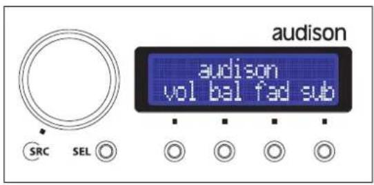
DRC - Digital Remote Control
(not provided with TH amplifier)
The DRC is a microprocessor digital system providing remote control and monitoring of the TH amplifiers. Once connected it performs important functions such as:
- Source selection (it also provides the ability to use the optical digital input as main source, checking its main volume)
- Main volume control
- Subwoofer volume control
- Right/ left balance control
- Front/rear Fader control
- Dual Power working memory Manager
- Status Monitor for all the amplifiers in the system
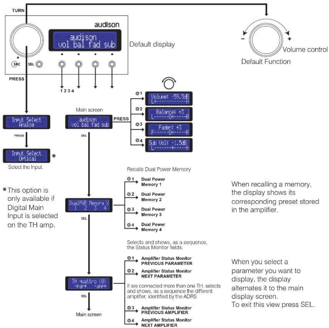
flowchart
graph TD
    A["TURN"] --> B["audison vol bal fad sub"]
    B --> C["Default display"]
    C --> D["Volume control"]
    D --> E["Default Function"]
    E --> F["Main screen"]
    F --> G["Input Select Analos"]
    G --> H["Select the Input."]
    H --> I["Input Select Optical *"]
    I --> J["DualPUR Memory X 1 2 3 4"]
    J --> K["TH sustro (0) -Part -Part+"]
    K --> L["Main screen"]

    M["TURN"] --> N["SYNC SRC SEL ○"]
    N --> O["PRESS 1 2 3 4"]

    P["RECALS Dual Power Memory"] --> Q["○1: Dual Power Memory 1"]
    P --> R["○2: Dual Power Memory 2"]
    P --> S["○3: Dual Power Memory 3"]
    P --> T["○4: Dual Power Memory 4"]

    U["START"] --> V["○1: Amplifier Status Monitor PREVIOUS PARAMETER"]
    U --> W["○2: Amplifier Status Monitor NEXT PARAMETER"]
    U --> X["If are connected more than one TH, selects and shows, as a sequence the different amplifier, identified by the ADRS"]
    U --> Y["○3: Amplifier Status Monitor PREVIOUS AMPLIFIER"]
    U --> Z["○4: Amplifier Status Monitor NEXT AMPLIFIER"]

    style A fill:#f9f,stroke:#333
    style D fill:#ccf,stroke:#333
    style E fill:#cfc,stroke:#333
DRC - Digital Remote Control
Info and Alert sentences
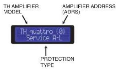
Amp off
Left or right A channel general protection. Call Audison Technical Support.
Amp off
Left or right B channel general protection. Call Audison Technical Support.
Autoreset
Left or right A channel overload protection. Check speaker load.
Autoreset
Left or right B channel overload protection. Check speaker load.
Event's alert
Left or right A channel output is reaching distortion threshold.
Event's alert
Left or right B channel output is reaching distortion threshold.
Autoreset
TH quattro (8) Ov. Temperature
Thermal protection. Check environmental temperature and/or use a low bias AMC setting.
Autoreset
Rare contact with ground occurs. Stop listening and check speaker cables.
Event's alert
PC control DRC is disabled
The PC is connected and ACNet software is running. The DRC is disabled.
DRC - Digital Remote Control
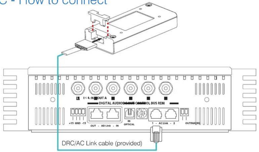
DRC - How to connect
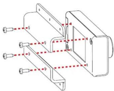
DRC - How to install
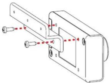
natural_image
Technical line drawing of a mechanical assembly with mounting holes and a central bracket (no text or symbols)External mountingFlush mounting
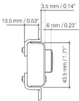
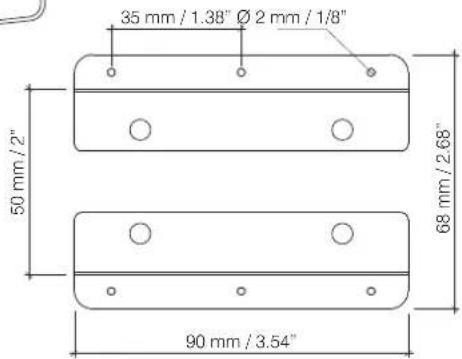
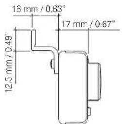
ACNet - Audison Control Network
Software to control Audison amplifier
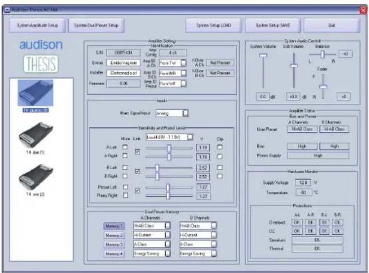
Hardware Requirements:
1024x768 Display Optimized - 96 dpi Font size - 1 x USB port (1.1 compliant)
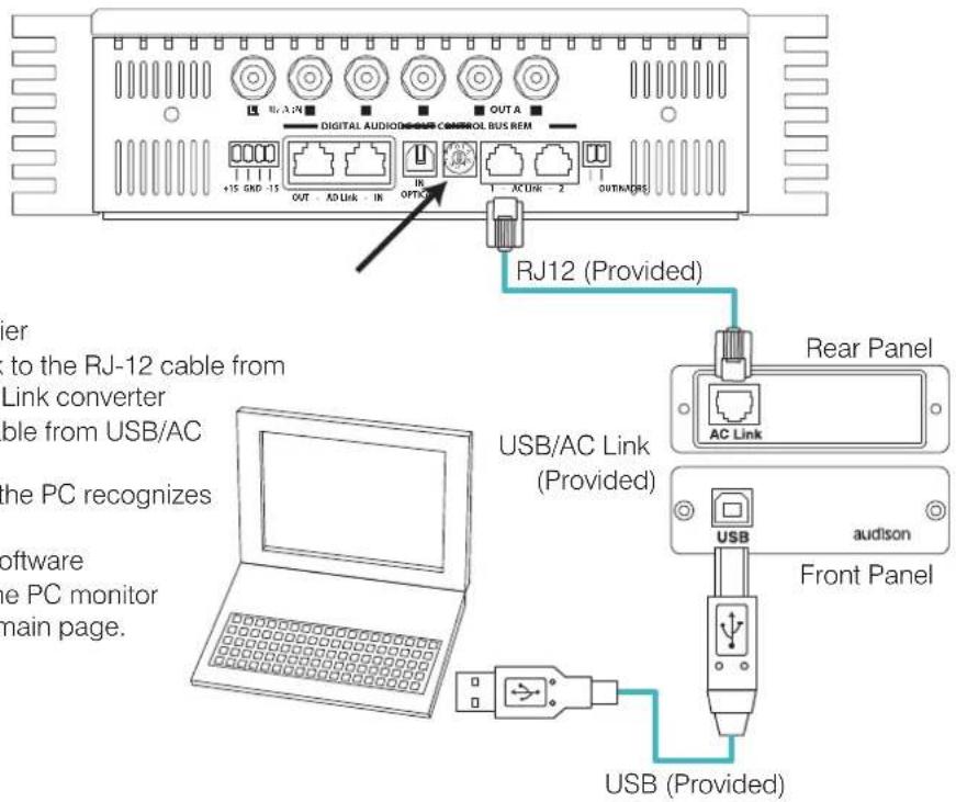
1 - Switch on the PC
2 - Switch on the amplifier
3 - Connect the AC Link to the RJ-12 cable from the TH to the USB/AC Link converter
4 - Connect the USB cable from USB/AC Link converter to PC
5 - Wait 5/10 secs until the PC recognizes the USB connection
6 - Launch the ACNet software
7 - If everything is OK the PC monitor displays the software main page.
ACNet - Audison Control Network
Functions Description
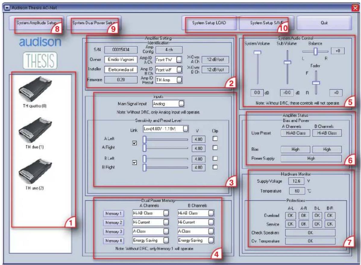
1 • SYSTEM DISPLAY: On this area the TH amplifiers connected to the system through the ACLink will be displayed. This screen will show the TH amplifier model name and its ADRS.
2 • IDENTIFICATION: This area shows report boxes and active fields, which enable the identification of each single amplifier.
3 • INPUTS: In this section it's possible to adjust each feature relating to the TH amplifier inputs
4 • DUAL POWER MEMORY: This menus allow the function setting for each amplifier separately.
5 • SYSTEM AUDIO CONTROL: The sliders in this area operate on the low level audio controls of the whole system.
6 / 7 • AMPLIFIER STATUS: This section is the real monitor of the amplifier's vital functions.
8 • SYSTEM AMPLITUDE SETUP: This function enables the input sensitivity of the amplifiers in the system.
9 • SYSTEM DUAL POWER SETUP: This function enables the function setting of all the amplifiers in the system.
10 • SYSTEM SETUP LOAD/SAVE: It guarantees the saving of the whole system setup or the loading of setups previously saved.
ACNet - Audison Control Network System Display
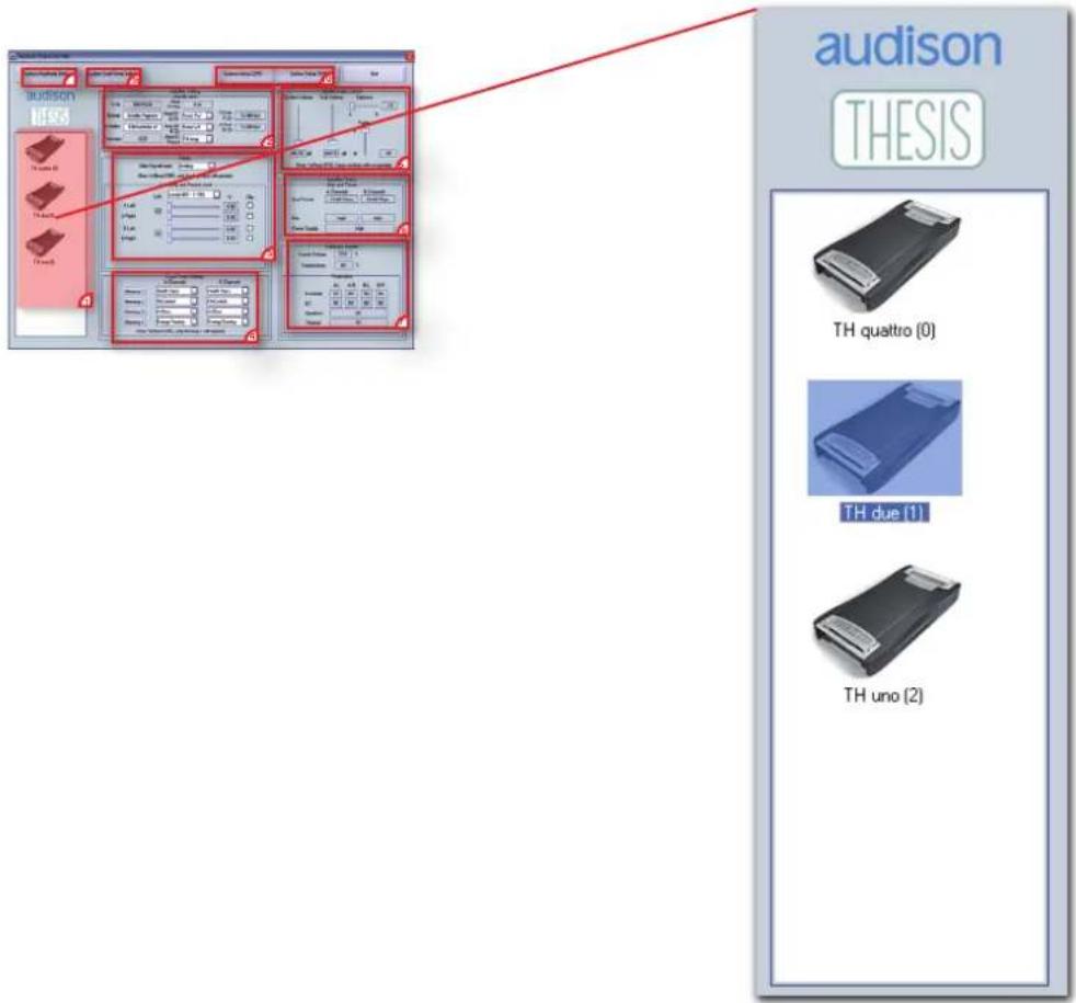
When installing a system composed by TH amplifiers it's possible to create a network between them by using ACLink series connection.
It is fundamental that a different ADRS starting from zero is assigned to each amplifier (see page 18).
In this way, when the software is turned on, the system will be able to automatically recognize which amplifier is present in the network.
This display will show all the "linked" amplifiers creating an icon corresponding to the model, the model name and the ADRS set during the installation.
The ACNet software allows the user to work either on one single amplifier or on the whole system.
In order to understand the use of the software we will work on a three way system + sub, multi-amplified, using a TH quattro on Tweeter and Midrange, TH due on Woofer and TH uno on Subwoofer.
For example, to work on a TH due double click on its dedicated icon. The name will be highlighted and its corresponding data will be displayed in the specific fields.
ACNet - Audison Control Network
Amplifier Setting: Identification
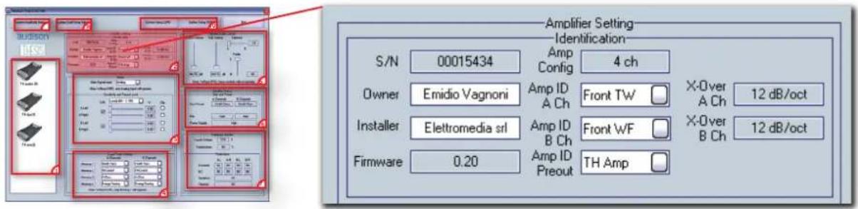
The amplifier identification provides its S/N - serial number (fixed), the owner name (free-text), the installer name (free-text) and the Firmware release included in the microprocessor inside the TH amplifier.
The ACNet area shows the amplifier configuration (mechanically set in the TH Input Panel) and allows the Amp ID and AmpPreout setting through a drop-down menu.
The report boxes on the right confirm if any crossover modules have been used inside the amplifier and which slope setting has been given.
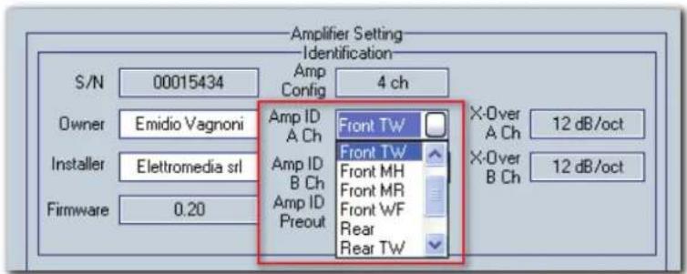
The drop-down menu displays the available values to be assigned to the amplifier depending on its configuration / functioning modes.
For example, if the amplifier it's mono set, the available ID will be the specific ones for the mono setting
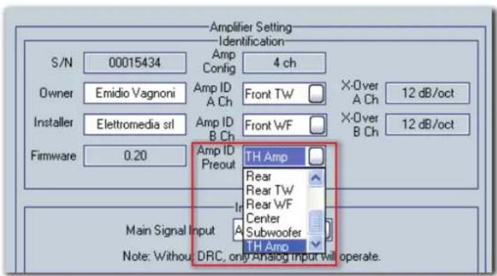
If the system is also composed by non-TH amplifiers, they can be managed by attributing an ID to the Pre Out connected to them. The menu default option is "TH AMP", because generally a TH amp (provided with its specific Amp ID already) is connected to the Pre Out.
ACNet - Audison Control Network
Amplifier Setting: Inputs
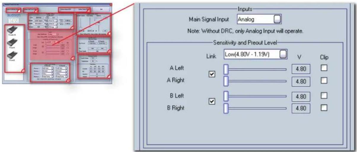
As for the ASC Setup Amplifier, it is necessary to set the system whenever wanting to use the digital input. In this area it is necessary to select the Main Signal Input for each amplifier connected to the system Example:
- If the amplifier being set is the first of the network to receive the signal from an external source, it is necessary to specify if it is an analog or digital one, by selecting Analog or Optical Master.
- If it is connected to both an analog and a digital source, select Optical Master and manage the sources switch through the DRC.
- If the amplifier being set receives the signal from another TH amp, connected in analog and digital AD Link, select Optical Slave.
- If the amplifier being set receives the signal from an external audio processor (Ex: Audison Bit One) select AD Link.
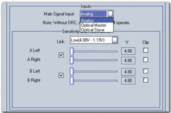
The note warns that if the DRC is not connected to the system, even selecting a digital input, when ACNet software will be switched off, only the Analog Input will operate.
ACNet - Audison Control Network
Amplifier Setting: Sensitivity and Preout Level
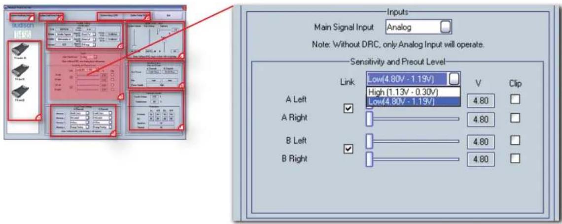
From this section featuring drop down menus, it is possible to regulate each amplifier's input sensitivity, acting also on the High/Low Level.
There are sliders for each channel which can work singularly or together if "linked". The software enables the fine tuning between right and left, acting on the corresponding slider. The software will show the level measured in V.
The LED Clip flashes when the max level is reached during tuning or playing.
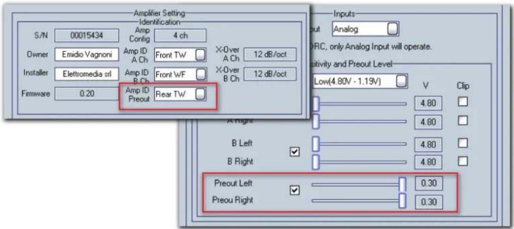
When using a non-TH amplifier to be controlled by DRC, an ID must be assigned to the Pre Out where it is connected. In this way it is still possible to manage the TH Preout sensitivity.
The specific sliders will come into view only when a name which is not TH Amp is given to the active field.
ACNet - Audison Control Network
Amplifier Setting: Dual Power Memory
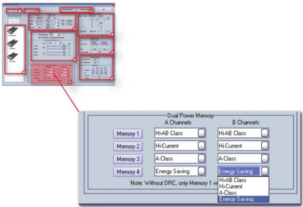
In this section the TH amps operating modes memories can be selected.
The available preset are: Hi-AB Class (default), Hi-Current, A-Class, Energy Saving. They can be assigned to each single memory by using the drop down menus.
The memories can be recalled through the Memory keys 1 / 2 / 3 / 4 but when ACNet software is switched off, if the DRC is not connected to the system, the function selected on Memory 1 will be operating.
TH uno and TH due can only work with one preset, while TH quattro can work with one preset on A Channels and one on B Channels.
Note: When the preset A-Class or Energy Saving is assigned to A Channels, this will be automatically applied to B Channels. Please refer to the following table:
TH quattro
| 1 | 2 | 3 | 4 | 5 | 6 | |
| Channels A | Hi-AB Class | Hi-Current | Hi-AB Class | Hi-Current | A Class | En.Saving |
| Channels B | Hi-AB Class | Hi-Current | Hi-Current | Hi-AB Class | A Class | En.Saving |
ACNet - Audison Control Network System Audio Control
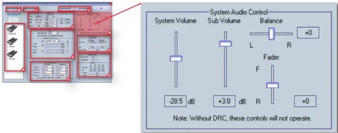
These controls act on the whole system:
- System Volume: it's the main volume control of the system, the slider on Min position switches on the muting and shows "MUTE" in the specific box. The adjustment starts from -60 dB (muting) up to 0 dB Max, 0,5 dB steps.
- Sub Volume: it's the specific volume control for the subwoofer, the slider on Min position switches on the muting and shows "MUTE" in the specific box. The adjustment starts from -12 dB (muting) up to +6 dB Max, 0,5 dB steps.
- Balance: it's the control that allows the left and right balancing. When in central position (+0) the output volume between left and right it's identical. It's possible to unbalance the output volume of one channel compared to the other.
- Fader: t's the control that allows the Front and Rear balancing. When in central position (+0) the output volume between Front and Rear it's identical. It's possible to unbalance the output volume of one zone compared to the other.
The Amp ID of each single amplifier inside the system must be set correctly in order to operate the audio controls. The Sub Volume control, for example, will only operate on the amplifiers identified on the Amp ID as Subwoofer. The Balance control will operate on all the amplifiers characterized by the presence of a right and left channel (it will not operate on Central and Subwoofer).
The note warns that if the DRC is not connected to the system, when ACNet software is switched off, these controls will not operate.
ACNet - Audison Control Network
Amplifier Status
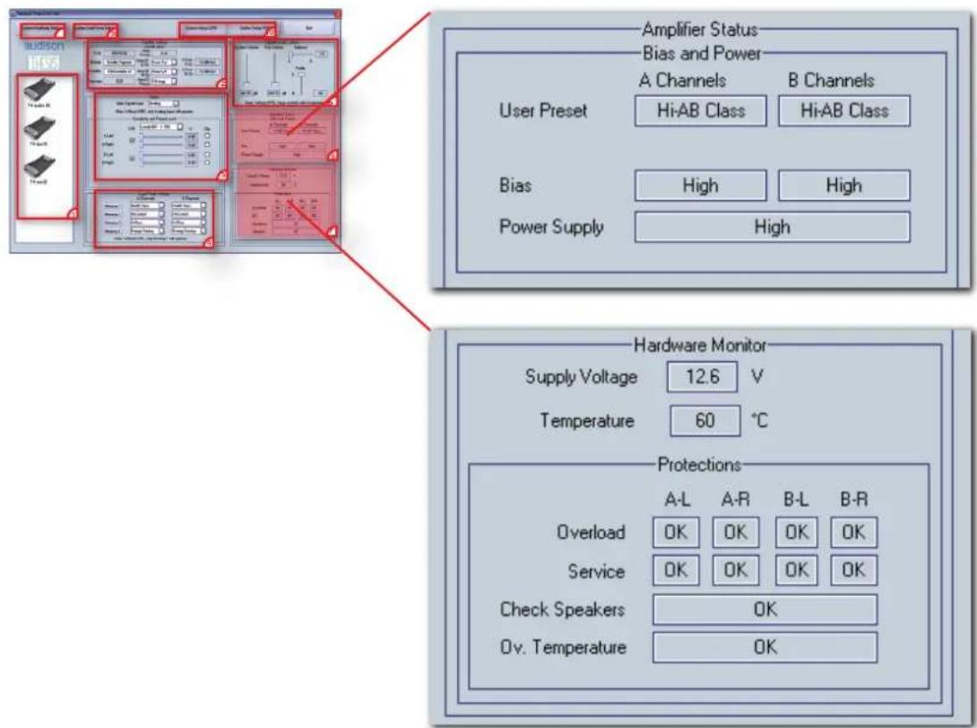
The ACNet software performs a real-time check-up of the amplifiers operating conditions.
Once an amplifier is selected, the parameters monitored by the ASC microprocessor are shown on the specific boxes.
Bias and Power
- User preset: displays the operating modes selected in the Dual Power Setting. For the TH quattro the operating modes of both channels A and B are shown.
- Bias: displays the bias current value corresponding to the preset in use.
- Power Supply: displays the power supply value corresponding to the preset in use.
Hardware Monitor
- Supply Voltage: displays the power supply voltage (V) measured on the amplifier terminals.
- Temperature: displays the amplifier working temperature measured in °C.
- Protections: the protection conditions are provided for each channel.
Overload: warns when an extremely low load has been connected to the amplifier speaker terminals or when a temporary overload has occurred;
Service: warns when DC current is coming out of the speaker terminals;
Speakers: warns when a short-circuit has occurred in the connection between amplifier and speakers;
Ov. Temperature: warns when an operating temperature, dangerous for the amplifier, has been reached.
ACNet - Audison Control Network System Amplitude Setup
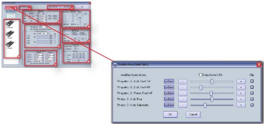
Once each single amplifier in the system has been set, it is possible to use the setup window above, which allows the sensitivity adjustment of all amplifiers of the entire system.
Using this section, it's possible to operate in an even mode on the amplifiers level tuning.
Sliders will work singularly on each amplifier and, selecting the Output Level LINK key, it's possible to tie all the sliders together and modify the main system level. The LED Clip flashes, when the max level is reached during tuning or playing.
Single level adjustment
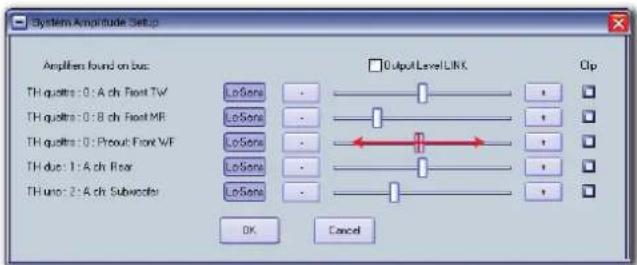
Whole system level adjustment
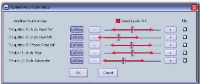
ACNet - Audison Control Network
System Dual Power Setup
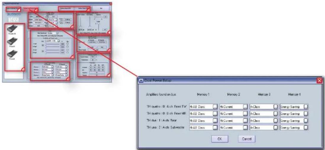
This setup enables the complete management of the operating mode of the amplifiers in the systems. The chart above presents in one window all the amplifier names and channels being used.
The fields are provided by default as in the example above. When wanting to achieve peculiar operating modes, depending on the acoustics results requested to the system, it is possible to modify the preset sequence.
Examples:
- To achieve the best quality/performance ratio system, select A-Class for TH quattro, Hi-AB Class for TH due and Hi-Current for TH uno.
- To achieve the best power/performance ratio system, select Hi-AB Class for TH quattro, Hi-Current for TH due and Hi-Current for TH uno.
- To achieve the highest audio quality system, use Memory 3.
- To achieve an unextended listening time while the car is parked, use Memory 4.
Technical Specifications
Power supply
Voltage 11 ÷ 15 VDC
Idling current:
A-Class 8.9 A
Hi-AB Class 6.6 A
Hi-Current 3.6 A
Energy Saving 2.6 A
Switched off 0.04 mA
Consumption @ 14.4 VDC, 1 Ω, Max musical power 105 A
Remote IN voltage 7 ÷ 15 VDC (1 mA)
Remote OUT voltage 12 VDC (20 mA)
Internal fuse (AFS) 100 A
Amplifier stage
Distortion - THD @ 1 kHz, 4 Ω, 90% Power 0.03 %
Bandwidth @ -3 dB, 2 VRMS, 4 Ω 5 ÷ 70k Hz
S/N ratio @ A weighted, 1 V, Max Power 104 dBA
Damping factor @ 1 kHz, 2 VRMS, 4 Ω
Input sensitivity (two ranges)
Input impedance (PRE IN)
Load impedance (Min @ Dual Power Mode - Hi-Current)
• 4 Ch
• 2 Ch
Output power (RMS) @ 14.4 VDC, 1% THD
Dual Power Mode - Hi-Current:
• 4 Ch @ 4 Ω
• 4 Ch @ 2 Ω
• 4 Ch @ 1 Ω
• 3 Ch @ 4 Ω
• 3 Ch @ 2 Ω
• 2 Ch @ 4 Ω
• 2 Ch @ 2 Ω
Dual Power Mode - A Class:
• 4 Ch @ 4 Ω
CEA Specifications
Output power @ 4 Ω, ≤ 1% THD + N, 14.4 V:
SN ratio (ref. 1 W output)
Inputs / Outputs / Filters
Inputs
Outputs
Filters
PRE / SP-DIF (Max 192 kHz/24 bit) OPTICAL and AD Link
PRE Bypass / AD link
2 x Removable kit (Hi-pass / Lo-pass / Band-pass 12/24 dB/oct)
32 steps 18 ÷ 7.5k Hz with 8 standard & 2 customizable modules
Size
B (Base) x L (Lenght) x H (Height) mm/inches
Weight kg/lbs
259×510×67/10"1/4×20"1/8×2"11/16
10.3/22.71
audison
www.audison.eu

- THESIS
- INDEX
- The Project
- Sections:
- General Part:
- Classic Domain:
- Digital Domain:
- Packaging Contents
- Available accessories (not included):
- Installation
- THES
- Fixing te
- Fixing template
- Rear Panel
- Functions Description
- How to remove the panel / the protection knob
- How to connect the speakers in 4 Ch mode
- How to connect the speakers in 3 Ch mode
- How to connect the speakers in 2 Ch mode
- Input controls
- How to move from one sensitivity range to another
- Front Panel
- CONTROL BUS
- DIGITAL AUDIO IN/OUT
- How to connect the remote
- Electronic Crossover
- Setup Xover Slope 12 dB (default configuration)
- TH in 3 Ch Mode Filtering B channels
- Setup Lo-pass Xover Slope 24 dB
- How to insert
- Example: Two Way, multi-amplified, TH amplifier Analog Input
- In order to build a Standard System you have to:
- In order to add DRC to the System you also need to:
- In order to adjust the system through the ACNet:
- REMARK:
- Example: Two Way+Sub, multi-amplified, TH amplifier Analog Input
- In order to adjust the system through the
- ACNet:
- Example: Three Way + Sub, multi-amplified, TH amplifier Analog Input
- Example: Three Way + Sub, multi-amplified, with and without TH amplifiers. Analog Input
- ASC (AMPLIFIER STATUS CONTROLLER)
- - Setup Amplifier:
- INPUTS AND PRE-AMPLIFIER
- ASC - Amplifier Status Controller
- Setup Amplifier: Main Input
- How to adjust the volume control and input selector using a digital source
- How to achieve same output volume level using an analog source (with its own volume control) and a digital source
- Setup Amplifier: Amp ID on 4 Ch Mode
- Example:
- Setup Amplifier: Amp ID on 3 Ch Mode
- !
- How to adjust the PRE OUT analog output
- Setup Amplifier : X-Over Slope of bridged channels (B) with TH quattro in 3 Ch mode
- TH quattro in 2 Ch mode
- ASC - Amplifier Status Controller DUAL POWER & BIAS CONTROL
- Setup Amplifier: DUAL POWER Settings
- How to change presets on the Memory (DRC required)
- Default configuration → Modified configuration
- Example: Three Way+ multi-amplified Sub, TH amplifiers Digital Input
- Example: Three Way + multi-amplified Sub, TH amplifiers Analog + Digital Input
- Example: Three Way + Sub, multiamplified with and without TH amplifiers. Analog + Digital Input
- ASC - Amplifier Status Controller Status Monitor
- Runtime Monitor
- Info and Alert sentences
- What the TH is doing
- What the display is showing
- What it means
- DRC - Digital Remote Control
- (not provided with TH amplifier)
- ACNet - Audison Control Network
- Software to control Audison amplifier
- ACNet - Audison Control Network System Display
- Amplifier Setting: Identification
- Amplifier Setting: Inputs
- ACNet - Audison Control Network System Audio Control
- Amplifier Status
- Bias and Power
- Hardware Monitor
- ACNet - Audison Control Network System Amplitude Setup
- System Dual Power Setup
- Examples:
- Technical Specifications
- Power supply
- Amplifier stage
- CEA Specifications
- Inputs / Outputs / Filters
- Size
- audison
Brand : AUDISON
Model : Thesis TH quattro
Category : Receiver