NVR4X-STD-32TB-EU - Video recorder Avigilon - Free user manual and instructions
Find the device manual for free NVR4X-STD-32TB-EU Avigilon in PDF.


User questions about NVR4X-STD-32TB-EU Avigilon
0 question about this device. Answer the ones you know or ask your own.
Ask a new question about this device
Download the instructions for your Video recorder in PDF format for free! Find your manual NVR4X-STD-32TB-EU - Avigilon and take your electronic device back in hand. On this page are published all the documents necessary for the use of your device. NVR4X-STD-32TB-EU by Avigilon.
USER MANUAL NVR4X-STD-32TB-EU Avigilon
NVR4X-STD-16TB, NVR4X-STD-24TB, NVR4X-STD-32TB and NVR4X-STD-48TB
© 2020, Avigilon Corporation. All rights reserved. AVIGILON, the AVIGILON logo, AVIGILON CONTROL CENTER and AVIGILON APPEARANCE SEARCH are trademarks of Avigilon Corporation. Other names or logos mentioned herein may be the trademarks of their respective owners. The absence of the syn and ^® in proximity to each trademark in this document or at all is not a disclaimer of ownership trademark. Avigilon Corporation protects its innovations with patents issued in the United States of A and other jurisdictions worldwide (see avigilon.com/patents). Unless stated explicitly and in writing, no license is granted with respect to any copyright, industrial design, trademark, patent or other intellect property rights of Avigilon Corporation or its licensors.
This document has been compiled and published using product descriptions and specifications available the time of publication. The contents of this document and the specifications of the products discuss herein are subject to change without notice. Avigilon Corporation reserves the right to make any such changes without notice. Neither Avigilon Corporation nor any of its affiliated companies: (1) guarantees completeness or accuracy of the information contained in this document; or (2) is responsible for year of, or reliance on, the information. Avigilon Corporation shall not be responsible for any losses or (including consequential damages) caused by reliance on the information presented herein.
Avigilon Corporation avigilon.com
PDF-NVR4XSTD-A
Revision: 1 - EN
20200610
Table of Contents
Introduction .1
Before You Start 1
Overview 2
Front View 2
Back View 3
Installation .4.
Package Contents 4
Installing the Sliding Rack Rails and Cable Management..Arm..4....
Connecting Cables 4
Installing the Bezel 4.
Set Up Your Operating System 5
Logging into Windows 10 for the First...Time....5
Logging into Windows Server for the First Time 6
Connecting to ACC Software and ACS 8
Activating and Configuring ACC Software 8
Connecting to Avigilon Cloud Services 8
Troubleshooting 8
Network Configuration 8
Checking System Health 8
Operating System Recovery By Avigilon Recovery Partition 8
Operating System Recovery By External USB 10
Advanced Features 11
Checking System Health.... 11
ACC Client Site Health 11
Server Administrator Software System Health 11
Replacing a Hard Drive Blank 12
LED Indicators 15
Diagnostic Indicators 15
Power Status Indicators 16
Network Link Status Indicators.... 16
Hard Drive RAID Status Indicators 17
For More Information.... 18
Introduction
The Avigilon Network Video Recorder is preloaded with the Avigilon Control Center software and is configured for maximum performance and reliability. The Network Video Recorder can be easily integrated into any existing Avigilon security system, or act as the base of a new site.
Before You Start
Avigilon recommends the use of an uninterruptible power supply (UPS) system to protect your video surveillance system hardware. A UPS system is used to protect critical equipment from mains supply problems, including spikes, voltage dips, fluctuations and complete power failures using a dedicated battery. It can also be used to power equipment during the time it takes for a standby generator started and synchronized.
Any UPS connection must include configuration to shut down the operating system on the appliance battery power is low or there is 15 minutes of power remaining.
It is recommended that cameras not be connected to the appliance until after the appropriate netw configuration has been set up.
Overview
Front View
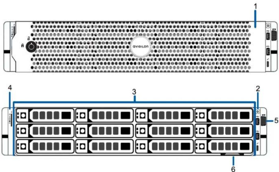
text_image
AVIGILON 1 2 3 4 5 61. Bezel
Protects against unauthorized physical access to the hard drives.
2. Power button
Controls the power supply to the recorder.
3. Hard drives
Provides access to hot-swappable hard drives. There are LED indicators on each hard drive. Some drives may contain an empty hard drive tray.
4. Diagnostic indicators
Provides information about system operations.
For more information, see LED Indicators on page 15.
5. Video connector
Accepts a VGA monitor connection.
6. Information tag
Provides the product service details and support information.
Back View
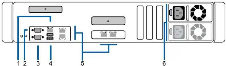
text_image
Diagram of a device rack with labeled ports and connectors, showing connections between numbered ports 1 to 6.* = Expansion slots in use
- Out-of-Band Management (OOBM) connector
Accepts an OOBM RJ-45 connection.
- Serial connector
Accepts connections to serial devices.
- Video connector
Accepts a VGA monitor connection.
- USB connectors
Accepts USB connections to external devices.
- RJ-45 1 Gbps Ethernet ports (4)
Accepts Ethernet connections to multiple networks.
- Power supply
Power supply unit and slot for the optional, redundant, 2nd power supply.
Installation
Package Contents
Ensure the package contains the following:
• Avigilon Network Video Recorder
- Rack sliding rail assembly kit
- Cable management arm assembly kit
- Bezel and key
- Power cable
Installing theSliding Rack Railsand Cable Management A
If the recorder will be kept in a server rack, install the Sliding Rack Rails and the Cable Manager (CMA) provided in the recorder package. Follow the procedures outlined in the Rack Installation Instructions and the CMA Installation Instructions provided in the assembly kits.
Note: The supplied Sliding Rack Rails are compatible with square and round hole
Connecting Cables
Refer to the diagrams in the Overview section for the location of the different connectors. Make the following connections as required:
-
Connect a KVM switch or separate keyboard, mouse and monitor to the recorder.
-
The keyboard and mouse can be connected to any USB port on the recorder.
• The monitor can be connected to any video connector at the front or back of the rec -
Connect the recorder to your network by plugging an Ethernet cable into one of the Ethernet
- Connect a power cable to the power supply at the back of the recorder.
- Press the power button on the front of the recorder. Check that the recorder LED indicators the correct status. For more information on the different LED status indicators, see LED Indicators on page 15.
Installing the Bezel
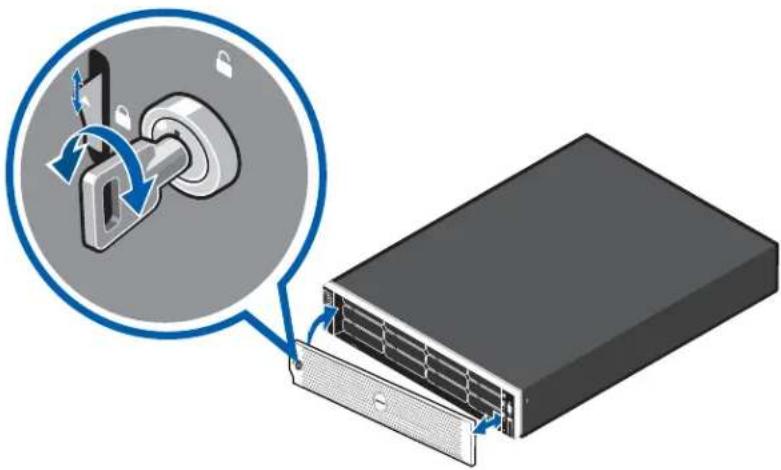
The bezel can be installed on the front of the recorder to help protect the hard drives against I access.
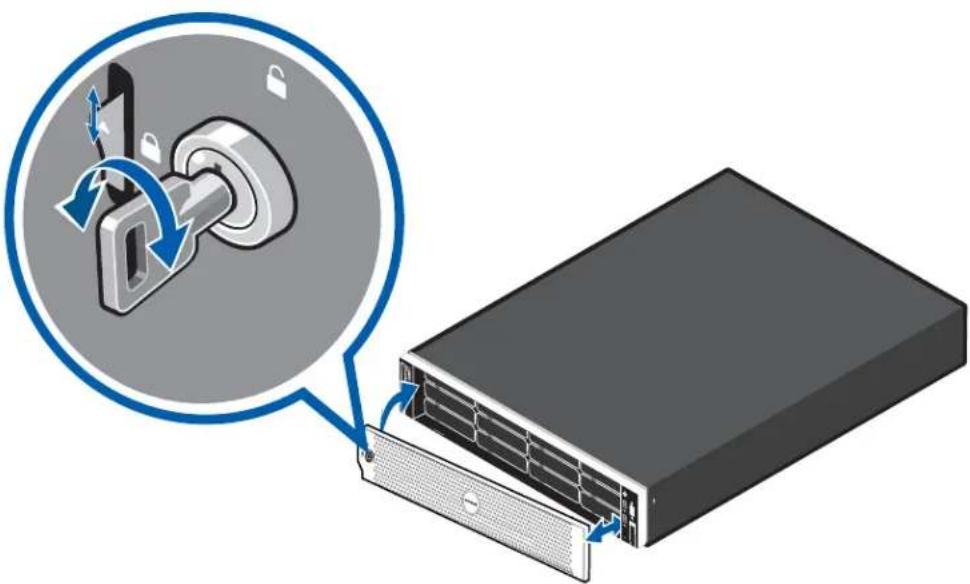
natural_image
Illustration of a server rack with a lock mechanism and a magnified view showing the internal components (no text or symbols present)- Align and insert the right end of the bezel until it clicks into place.
- Push the left end of the bezel into the front of the unit until it clicks into place.
- Use the provided key to lock the bezel.
Set Up Your Operating System
The Avigilon Network Video Recorder is preloaded with a Windows 10 or Windows Server 2016 operation system. Determine which operating system you have, and then follow the instructions in the corresponding procedure to set up that operating system.
• Windows 10. For more information, see Logging into Windows 10 for the First Time below.
- Windows Server 2016. For more information, see Logging into Windows Server for the First Time on the next page.
Logging into Windows 10 for the First Time
After the recorder starts, you will need to configure the Windows operating system for the first tim
- On the first screen, the MICROSOFT SOFTWARE LICENSE TERMS and AVIGILON CONTROL CENTER® SOFTWARE END USER LICENSE AGREEMENT are displayed. Review the terms and click Accept.
- Select Join a local Active Directory domain.
Note: This prompt appears only if an Active Directory is present on the network. Windows Help and Support files for more information.
- Enter a user name for accessing the Windows software.
- Enter a password and password hint for the user name and click Next.
-
Once logged in, the recorder will go through initial system setup, and ask to select the Ver AvigilonControl Center to use:
-
Use ACC 7.x.x (recommended). Select this option to use the latest version of the ACC software.
- Downgrade to ACC 6.x.x. Select this option to downgrade your NVR to version 6.x.x. This older version of the ACC software would not support newer features such as facial record and the Focus of Attention interface.
You are logged in to the Windows environment. The Avigilon Control Center Admin Tool and ACC client automatically start up.
Note: If you are performing operating system recovery, the ACC client does not automatically start up. For more information about running the local ACC install Operating System Recovery By Avigilon Recovery Partition on page 8.
Proceed to activate the license for the Avigilon Control Center software on your Network Video Rec
Logging into Windows Server for the First Time
After the recorder powers up, you will need to configure the Windows operating system for the fir
- On the first screen, scroll through the list and select your preferred language.

text_image
Hi there Let's get a few basic things out of the way. čeština dansk Deutsch English español français Italiano Nederlands norsk bokmål NextFigure 1: The language selection screen during initial Windows software set up. (Used with permission from Microsoft.)
- Select the country/region, preferred app language, and keyboard layout, then click Next. NOTE: If a language other than English is selected, the server will restart. This is a normal Windows behavior, please proceed with step 3 once the server has finished restarting.
- The End User License agreements are displayed. Review the terms then click Accept.
-
On the Customize settings screen, set a password for the local administrator account. The password must:
-
Have a minimum length of 7 characters.
- Meet complexity requirements. See https://technet.microsoft.com/enca/library/cc956977.aspx for details.
You cannot reuse your last 24 passwords.
The password will expire in 42 days.
- Press Ctrl+Alt+Delete to unlock and input the login password created in the previous step.
-
Once logged in, the recorder will go through initial system setup, and ask to select the ver Avigilon Control Center to use:
-
Use ACC 7.x.x (recommended). Select this option to use the latest version of the ACC software.
-
Downgrade to ACC 6.x.x. Select this option to downgrade your NVR to version 6.x.x. This older version of the ACC software would not support newer features such as facial record and the Focus of Attention interface.
-
The Setup dialog will start configuring the system storage. This process may take up to 5-depending upon the size of the storage volume.
-
The Avigilon Control Center Software will start running automatically and the NVR Analytics Kit configured.
- Once the setup procedure is complete, the system will restart.
Proceed to activate the license for the Avigilon Control Center software on your Network Video Rec
Connecting to ACC Software and ACS
Once you have deployed your NVR, you should activate your ACC software and connect to Avigilon Services (ACS).
Activating and Configuring ACC Software
- Initial ACC™ System Setup and Workflow Guide
- ACC 7 Help Center
Printable versions of these guides are available on the Avigilon website: avigilon.com/support/software/.
Connecting to Avigilon Cloud Services
After activating your ACC software, you can connect your ACC site to the cloud, free of charge, advantage of the capabilities and features that provide centralized access across distributed systems.
To connect your site to Avigilon Cloud Services, see help.avigilon.com/cloud.
For information about the cloud services, see Avigilon Cloud Services Support.
Troubleshooting
Network Configuration
By default, the Network Video Recorder acquires an IP address on the network through DHCP. If you to set up the recorder to use a static IP address or any specific network configuration, see the Windows Help and Support files for more information.
Checking System Health
You can check on the health of the system components in the Site Health in the ACC Client sc Site Health in the ACC Client User Guide for more information.
Operating System Recovery By Avigilon Recovery Partition
If you need to recover the Windows operating system, the NVR includes an onboard Avigilon recovery partition that is separate from the operating system partition. The advantage of using the Avigilon repartition is that you do not need an internet connection.
Important: Your operating system drive will be erased and restored to factory settings. Before you proceed with operating system recovery, complete any necessary backups of custom configuration and video recordings. For more information about ACC software backups avigilon.com/recovery.
Note: Depending on when your NVR was shipped, it is recommended that you can network when possible to install updates for Windows and ACC Client software after recovery is completed. For more information about ACC software installations, see avigilon.com/recovery.
-
Start operating system recovery in one of the following ways:
-
On your Windows desktop, select 📋 and then hold down the Shift key and select Restart.
- On your locked Windows screen, Select and then hold down the Shift key and select Restart.
-
During direct boot of the operating system, repeatedly press the down-arrow key and select the partition.
-
On the Choose an option screen, select Use another operating system.
-
Select the OS Recovery partition.
-
On the Avigilon Recovery window, select Recover.
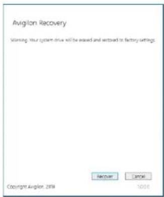
text_image
Avigilon Recovery Warning: Your system drive will be eased and saved to factory settings. RECOVER CANCEL Copyright Avigilon, 2014 1006Allow up to half an hour for the recovery to complete.
- After system reboot, complete the Windows setup process.
For more information about setting up a Windows Server 2016 operating system, see Logging into Windows Server for the First Time on page 6.
Note: During the Windows setup steps, you will not be asked to choose a the ACC software. The ACC software installation is covered in the following s
- Navigate to C:\Avigilon\Control Center Installation Files, and run the ACC installer for the version of ACC software in use at your site.
Operating System Recovery By External USB
If you need to recover the Windows operating system on the Network Video Recorder and you have to the internet, download the latest Avigilon Recovery Image from avigilon.com/recovery and refer to
Support and Downloads for the following information:
• Minimum size of the USB recovery device
- Creating an external USB recovery device
• Recovering the operating system from an external USB recovery device
The general steps are:
- Load the Avigilon Recovery Image onto a USB recovery device.
- Plug the USB recovery device into the workstation.
- Repeatedly press the F12 key while booting the workstation.
- On the UEFI Boot menu, select the USB recovery device.
Advanced Features
Checking System Health
You can check your system health through the ACC Client Site Health or with the Server Administ software.
ACC Client Site Health
You can check on the health of the system components in the Site Health in the ACC Client sc Site Health in the ACC Client User Guide for more information.
Server Administrator Software System Health
The Server Administrator software is pre-installed on the recorder. The software provides information at the recorder's system operation status, and gives you remote access to the recorder for recovery operations.
If one of the LED indicators on the recorder is flashing an error warning, the Server Administrator details about the problem. For more information about the LED indicators, see LED Indicators on page 15.
- Open the Server Administrator.
- To open the Server Administrator locally, double-click the Server Administrator shortcut icon on the desktop.
- To open the Server Administrator remotely, open a web browser and enter this address: https://
For example: https://192.168.1.32:1311/ or https://localhost:1311/.
If you are using an intranet connection, your browser may display an error message. Allow the browser to ignore the certificate warnings.
-
If asked to log in, enter the Windows software administrator username and password that was configured for the recorder.
-
On the Server Administrator home page, the health of the system components are displayed workspace on the right.
- To see the health of other system components, expand and select a different component from the System Tree on the left.
- The table displayed in the workspace lists system components and their status:
The system component is running normally.
The system component has a non-critical warning.
The system component has a critical failure.
The system component status is unknown.
• To see the details of a system component, select the system component from the works
The Server Administrator is also used to customize the Redundant Array of Independent Disks (RAID) settings, assign a hot spare and remotely monitor the system health. For more information about the in the Server Administrator, see the Help system provided in the software.
Replacing a Hard Drive Blank
The hard drives on the Network Video Recorder are set up in a RAID configuration. This allows it to be recorded across several hard drives.
If one or two hard drives fail, there is enough information on the other hard drives for the record continue recording video.
Depending on the recorder model, there may be hard drive blanks at the front of the recorder. Y replace the blanks with hard drives as required.
- Remove the bezel.
natural_image
Illustration of a server rack with a lock mechanism and a magnified inset showing the internal components (no text or symbols)a. Unlock the bezel.
b. Push the release button next to the lock.
c. Pull the left end of the bezel then unhook the right end to remove the bezel.
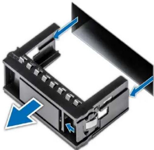
- Press the release button and slide the blank out of the hard drive slot.
natural_image
3D diagram of a black plastic enclosure with blue directional arrows indicating movement or force (no text or symbols)- Insert the hard drive all the way into the recorder then push the handle against the hard into place.
- Open the Server Administrator application and expand the System Tree.
The new hard drive should be automatically added to the Physical Disks list. The list is typical available here: System > Storage > PERC H730P > Connector 0 (RAID) > Enclosure (Backplane) > Physical Disks.
- Assign a task to the new hard drive or allow it to exist as an extra storage drive.
It is recommended to use the new hard drive as a hot spare. Hot spares are hard drives available on standby in the event of a hard drive failure in the RAID. If that occurs, you do the system to automatically redirect recording to the unused hard drive.
To assign the new hard drive as a hot spare:
a. In the Task list, select Assign and Unassign Global Hot Spare.
b. Click Execute.
If the new hard drive is not displayed in the Server Administrator, try one of the following:
- Refresh the browser.
-
Reboot the recorder.
-
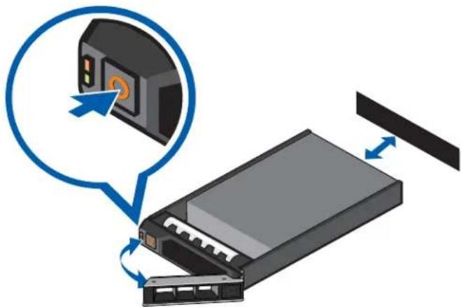
Locate the failed hard drive at the front or back of the recorder.
natural_image
Illustration of a computer drive with a blue speech bubble and directional arrows indicating process (no text or symbols)- Press the release button on the front left of the hard drive.
- When the handle is released, pull the hard drive out of the recorder.
- Remove the four screws from the side of the hard drive carrier.
- Lift the failed hard drive out of the carrier.
- Insert a new hard drive into the carrier then screw it into place. The hard drive connectors the back.
- When the hard drive is secured in the carrier, insert the hard drive back into the recorder.
- Once the hard drive is inserted all the way in, push the handle against the hard drive to place.
The recorder immediately starts rebuilding the hard drive. The progress is displayed in the Server Administrator. This may take several hours.
LED Indicators
The following tables describe what the LEDs on the Network Video Recorder indicate.
Diagnostic Indicators
The diagnostic indicators on the front panel highlight system issues during system startup.
Note: The diagnostic indicators only light-up when the recorder is powered.
| LED Indicator | Description |
| Hard drive | Blinks orange — the hard drive is experiencing an error. |
| Temperature | Blinks orange — there is a thermal error.Errors include:temperature out of rangefan failureCheck that the fans are functioning correctly and the air vents are not blocked |
| Electrical | Blinks orange — there is an electrical error.Errors include:voltage out of rangefailed power supplyvoltage regulatorCheck the power status indicator to confirm if it is an issue with the power : |
| Memory | Blinks orange — there is a memory error. |
| PCIe | Blinks orange — there is a PCIe card error.Restart then upgrade the device firmware if the error persists. |
| System health and System ID | Blue — powered and in good healthBlinking blue — System ID mode activeOrange — fail-safe modeBlinks orange — there is an error |
Power Status Indicators
The power button on the front lights up when power is on.
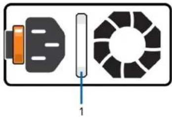
Additional information about the power supply is provided by the power status indicator on the power supplies at the back. The following table describes what the LEDs indicate:
natural_image
Diagram showing a device with a sensor and a circular component, no text or symbols presentFigure 2: (1) The power status indicator.
LED Indicator Description
| Off | Power is not connected. |
| Green | Power is supplied. |
| Flashing green | The firmware update is being applied to the power supply unit. |
| Flashing green then turns off | The redundant power supply is mismatched. This only occurs if you have a secondary redundant power supply installed. |
| Flashing orange | There is a problem with the power supply. |
Network Link Status Indicators
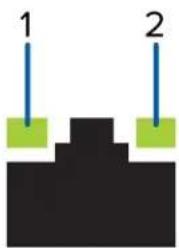
When the recorder is connected to the network, the recorder's connection status LEDs above the E port display the recorder's connection status to the network. The following table describes what the indicate:
natural_image
Simple diagram showing two vertical blue lines labeled 1 and 2 above a black stepped structure (no text or symbols beyond labels)Figure 3: (1) Link LED. (2) Connection activity LED.
LED Indicator Description
| Off | The recorder is not connected to a network. |
| Link LED — green | The recorder is connected to a network at the maximum port speed. |
| Connection Activity LED — blinking green | |
| Link LED — orange | The recorder is connected to a network at less than the |
LED Indicator Description
| Connection green | Activity LED — blinking | maximum port speed. |
| Link LED — green | The recorder is connected to a network at the maximum port speed and data is not being sent or received. | |
| Connection Activity LED — off | ||
| Link LED — orange | The recorder is connected to a network at less than the maximum port speed and data is not being sent or received. | |
| Connection Activity LED — off |
Hard Drive RAID Status Indicators
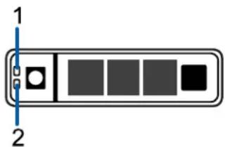
Each hard drive has its own set of LED indicators to show its activity and status.
text_image
1 2Figure 4: (1) Status LED. (2) Activity LED.
The Activity LED flashes green when the hard drives are working. The following table describes wh Status LEDs indicate:
LED Indicator Description
| Green | The hard drive is online. |
| Off | The hard drive is disconnected from the recorder. |
| Two short green flashes every second drive | the system is identifying a new hard drive, or preparing a hard drive for removal. |
| Flashes green, orange, then off | The hard drive is predicted to fail. |
| Four short orange flashes per second drive | hard drive has failed. |
| Flashes green slowly | The hard drive is rebuilding. |
| Blinks green for three seconds, orange for three seconds, and off for six seconds | hard drive rebuild has been aborted. |
Limited Warranty and Technical Support
Avigilon warranty terms for this product are provided at avigilon.com/warranty.
Warranty service and technical support can be obtained by contacting Avigilon Technical Support: avigilon.com/contact.
For More Information
For additional product documentation and software and firmware upgrades, visit avigilon.com/support.
Technical Support
Contact Avigilon Technical Support at avigilon.com/contact.