PD-117 - Tripod Oben - Free user manual and instructions
Find the device manual for free PD-117 Oben in PDF.


User questions about PD-117 Oben
0 question about this device. Answer the ones you know or ask your own.
Ask a new question about this device
Download the instructions for your Tripod in PDF format for free! Find your manual PD-117 - Oben and take your electronic device back in hand. On this page are published all the documents necessary for the use of your device. PD-117 by Oben.
USER MANUAL PD-117 Oben
natural_image
Close-up of a black camera head with red circular button labeled 'Open' and 'PD-T7', set against a red background (no readable text beyond branding)You're on steady ground™
Thank You for choosing Oben!
This sturdy Oben PD-117 3-Way Pan and Tilt Head offers precise, smooth operation, with independent control of each of the three axes.
The PD-117 has a durable and handsome low-reflectance powder-coated finish and ergonomic rubber handle grips for tilt-and-pan operation. Integrated bubble levels along each of the three axes ensure accurate, precise placement of the camera.
Please read this entire manual before using the PD-117 3-Way Pan and Tilt Head.
Note: Images are for illustrative purposes only. Actual product may vary.
Key Features
Attach Handles to Head 5
Mount Head to Tripod 5
Dual Locking Quick-Release 5
Mount Quick-Release Plate 6
Mount Camera to Head 6
Operation 6
Pan Locking Knob 6
Vertical Tilt Handle 7
Pan and Tilt Handle 7
Warnings 7
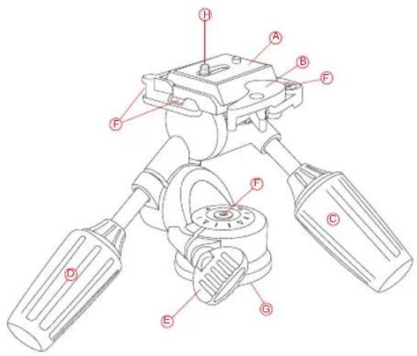
text_image
Technical diagram of a mechanical device with labeled parts A through H, showing assembly structure and component positioning.Quick-Release Plate
Dual-Locking Quick Release
- Vertical Tilt Handle
⑭ Pan and Tilt Handle
Pan Locking Knob
F Bubble Levels
3/8"-16 Tripod Mounting Thread
1/4" Camera Mounting Screw
natural_image
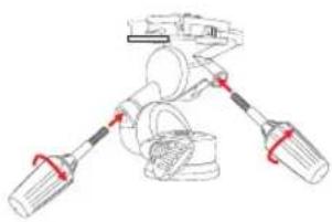
Line drawing of a mechanical device with two arms and a central component (no text or symbols)1. Attach Handles to Head
You must attach the control handles to the head before using it. There are two handles, as well as a Pan Locking Knob (which is pre-installed). The two handles to be installed are identical and either handle can be installed in either handle position on the head.
natural_image
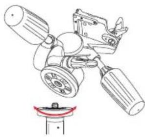
Diagram of a mechanical assembly with gears and a base mount (no text or labels)2. Mount Head to Tripod
To mount the head on a tripod, first tighten the pan locking knob on the head. Then, being careful to properly align the tripod stud with the head's mounting hole to avoid damaging them, rotate the head clockwise onto the tripod and hand-tighten.
natural_image
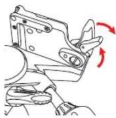
Mechanical component diagram showing a lever mechanism with red motion arrows indicating rotation (no text or symbols)3. Dual-Locking Quick-Release
The PD-117 is designed with a dual-locking quick-release latch to keep the camera securely in place on the head. To unlock the quick-release, press the small latch while pulling outward on the main latch at the same time.

4. Mount Quick-Release Plate
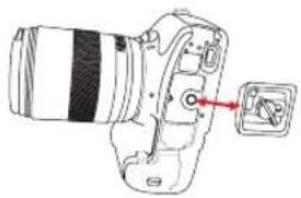
Mount the quick-release plate to the threaded hole on the base of your camera. The plate utilizes a 1/4"-20 screw that will fit most cameras. Align the mounting screw with the mounting socket on your camera and tighten the screw securely. After tightening the screw, fold the thumbscrew flat against the bottom of the quick-release plate.
5. Mount Camera to Head
After mounting the quick-release plate to your camera, ensure that the handles and knob on the head are securely tightened. To mount the camera to the head, first insert the side of the Quick-Release Plate that is opposite the quick-release latch. Then, press down on the side of the quick-release plate nearest the quick-release latch. The quick-release latch will automatically lock into place when the plate is pushed into the groove.
6. Operation
You should only loosen one locking handle at a time when adjusting your camera's position.
A. PAN LOCKING KNOB
The pan locking knob locks and unlocks the head, which allows you to rotate the head 360° horizontally.
natural_image
Diagram of a DSLR camera with a red arrow pointing to the lens (no text or symbols present)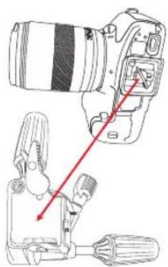
natural_image
Diagram of a DSLR camera with a clamping device and a separate camera setup, showing no text or symbols.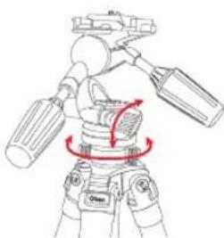
natural_image
Line drawing of a robotic arm with directional arrows indicating motion (no text or symbols)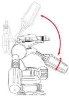
natural_image
Technical line drawing of a robotic arm with motion arrows indicating rotation (no text or symbols)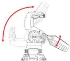
natural_image
Technical line drawing of a mechanical assembly with red arrows indicating motion or force direction (no text or symbols)Turn the knob counter-clockwise to unlock and clockwise to lock it. After positioning the head, make sure to securely tighten the knob.
C. VERTICAL TILT HANDLE
The vertical tilt handle allows you to move the position of the camera from horizontal to vertical, or anywhere in-between. Loosen the handle by turning it counterclockwise. Tighten it by turning it clockwise.
C. PAN AND TILT HANDLE
The pan and tilt handle allows you to tilt the camera up or down, or rotate it horizontally. Loosen the handle by turning it counterclockwise and tighten it by turning it clockwise. To rotate the camera horizontally using the pan and tilt handle, first loosen the pan locking knob.

Warnings:
- Do not exceed the head's maximum load capacity of 17.6 lb (8 kg).
- Ensure that all appropriate locks are engaged when necessary.
- Do not operate in saltwater. Dry head if it becomes wet.
- Remove the camera from the head during setup or transport.
- Avoid long-term exposure to sunlight.
- Keep out of reach of children.
Visit our website at ObenSupports.com for more Oben products.
© Copyright 2013 The Brands Group All other trademarks are the property of their respective owners