AC-1451 - Tripod Oben - Free user manual and instructions
Find the device manual for free AC-1451 Oben in PDF.


| Product Type | Tripod |
| Brand | Oben |
| Model | AC-1451 |
| Material | Aluminum alloy |
| Number of Leg Sections | 3 |
| Maximum Height | 145 cm (57 in) |
| Minimum Height | 45 cm (18 in) |
| Folded Length | 55 cm (21.7 in) |
| Weight | 1.5 kg (3.3 lb) |
| Maximum Load Capacity | 5 kg (11 lb) |
| Head Type | 3-way pan/tilt head (built-in) |
| Quick Release Plate | Yes, standard 1/4" screw |
| Leg Lock Type | Flip locks |
| Center Column | Gear-driven, detachable |
| Spreader | None (direct leg angle adjustment) |
| Compatible Devices | Cameras, camcorders, spotting scopes |
| Accessories Included | Carrying bag, user manual |
| Cleaning | Wipe with dry cloth; avoid solvents |
| Storage | Dry place, away from extreme temperatures |
| Safety Warning | Do not exceed max load; tighten all locks before use |
| Spare Parts Availability | Contact Oben support for replacement parts |
| Repairability | Modular design; some parts user-serviceable |
Frequently Asked Questions - AC-1451 Oben
User questions about AC-1451 Oben
0 question about this device. Answer the ones you know or ask your own.
Ask a new question about this device
Download the instructions for your Tripod in PDF format for free! Find your manual AC-1451 - Oben and take your electronic device back in hand. On this page are published all the documents necessary for the use of your device. AC-1451 by Oben.
USER MANUAL AC-1451 Oben
natural_image
Black tripod with black adjustable arms against a red background (no text or symbols visible)You're on steady ground™
Thank You for choosing Oben!
This versatile and durable Oben AC-1300/1400 series tripod includes an installed ballhead for quick and precise camera placement.
Adjusting the tripod's height is simple: open a flip lock to extend or retract each telescopic leg section separately. The center column locking knob releases the center column in a split second to slide up or down for further height adjustment. The center column is grooved to prevent it from rotating accidentally—it's also reversible for low-angle shooting.
Each leg can be positioned independently at 3 locking angles ( 24^ , 55^ , or 80^ ), and a built-in bubble level helps keep the tripod aligned with the horizon—both essential when working on uneven terrain. Closed-cell foam leg warmers on two of the legs protect your hands in hot or cold weather.
Please read this entire manual before using the AC-1300/1400 Series tripod.
Note: Images are for illustrative purposes only. Actual product may vary.
Key Features
Ballhead Operation
Leg Length Adjustment 6
Leg Angle Adjustment 6
Center Column Adjustment 7
Low-Angle Setup
Counterweight 9
Warnings 11
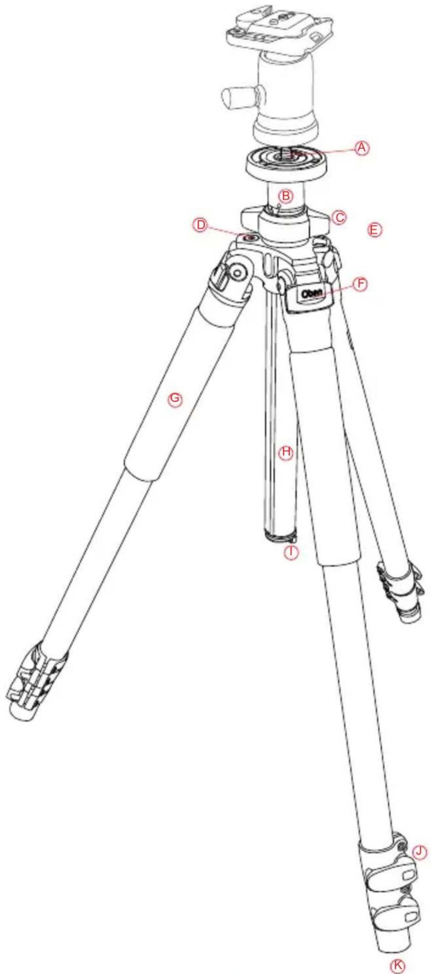
A Dual 3/8"-1/4"-20 head mounting screw
B Short split-column
© Center column locking knob
D Bubble level
E Strap mount
F Leg angle adjustment lock
G Closed-cell foam grip
H Grooved reversible center column
① Retractable and removable weight hook
Flip-style leg lock levers
K Rubber feet
1. Ballhead Operation
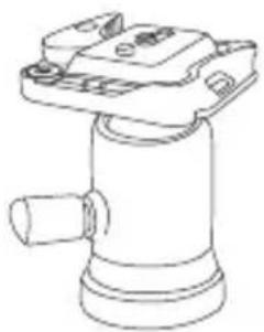
Refer to the included Ballhead Instruction Manual.
2. Leg Length Adjustment
A secure flip-lock design allows for rapid height adjustment for each telescopic tripod leg. To adjust the height of a leg, open a flip-lock lever, position the leg at the desired height, and close the lever to lock the leg in place.
3. Leg Angle Adjustment
For stable support when shooting on uneven terrain, each leg of the tripod can be individually set at a preset angle of 24^ , 55^ or 80^ .
To change a leg's angle, pull the adjustment lock outward and set the angle of the leg. Push the lock in to lock the leg at that angle.
natural_image
Line drawing of a mechanical component with no visible text or symbols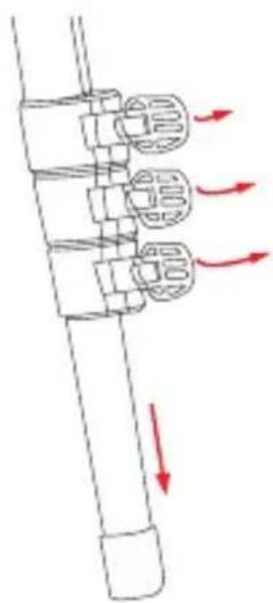
natural_image
Diagram of a mechanical assembly with directional arrows indicating motion or force (no text or symbols)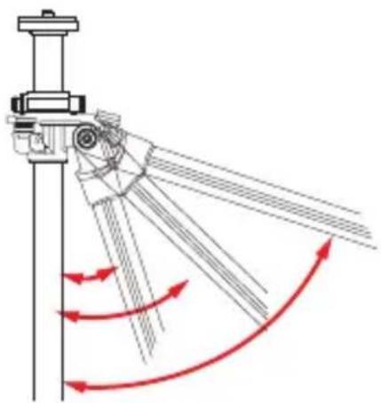
natural_image
Diagram of a mechanical linkage system with red curved arrows indicating motion or force direction (no text or symbols)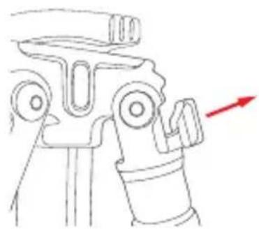
natural_image
Line drawing of a mechanical component with a red arrow indicating direction (no text or symbols)4. Center Column Adjustment
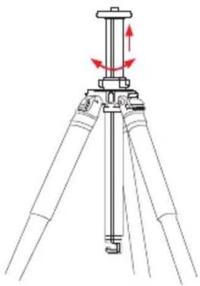
The sliding center column can be used to adjust the height of the camera. Fully extending the center column after the legs have been fully extended will place the camera at the highest position possible with this tripod.
ADJUST THE CENTER COLUMN
Turn the center column locking knob counterclockwise, adjust the center column to the desired height, and lock it in place by turning the center column locking knob clockwise. Ensure that the knob is secure, but do not over-tighten it to avoid damaging the tripod.
5. Low-Angle Setup
There are two ways to adjust the tripod for low-angle shots.
REVERSE THE CENTER COLUMN
- Remove the built-in weight hook from the bottom of the column by turning it counterclockwise and pulling it out of the column.
natural_image
Line drawing of a tripod-mounted surveying instrument with red directional arrows indicating motion (no text or symbols)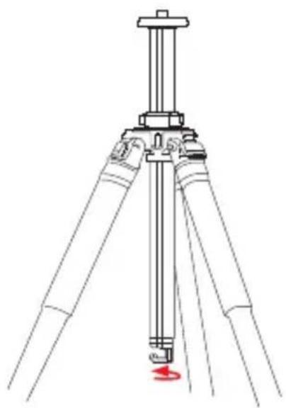
natural_image
Line drawing of a tripod-mounted surveying instrument with a red circular indicator on the base (no text or symbols)5. Low-Angle Setup (continued)
- Turn the center column locking knob counterclockwise to unlock the center column. Remove the center column from the tripod and remove the center column locking knob from the center column.
- Reverse the center column and insert it up through the bottom of the tripod top plate.
4.Slide the center column into the desired position. Turn the center column locking knob clockwise to lock it at the desired height.
SPLIT THE CENTER COLUMN
- Remove the weight hook from the bottom of the column by turning it counterclockwise and pulling it out of the column.
- Turn the center column locking knob counterclockwise to unlock the center column. Remove the center column from the tripod.
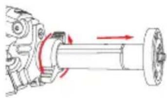
- Use the smallest included Allen wrench to loosen the Allen screw located near the top of the center column. When the Allen screw is loosened, unscrew the top part of the center column and remove it from the column.
natural_image
Mechanical assembly diagram showing a shaft and gear with directional arrows indicating motion (no text or labels)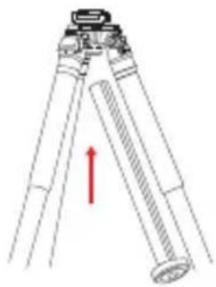
natural_image
Diagram of a tripod-mounted surveying instrument with a red upward arrow indicating direction (no text or symbols present)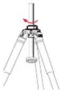
natural_image
Diagram of a tripod-mounted surveying instrument with a red arrow indicating rotation (no text or symbols present)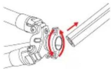
natural_image
Mechanical assembly diagram showing a rotating component with red arrows indicating motion (no text or symbols)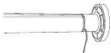
natural_image
Simple line drawing of a mechanical component with a flanged shaft and circular end (no text or symbols)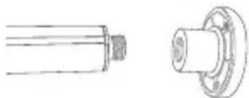
natural_image
Technical line drawing of a cylindrical mechanical component with flange and threaded shaft (no text or symbols)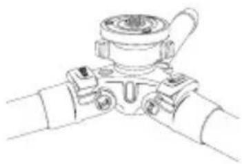
natural_image
Line drawing of a mechanical valve assembly with no text or symbols- Put the main column aside. Tighten the Allen screw with the Allen wrench so that the screw is flush with the surface of the center column. Insert the short column into the tripod and adjust to the height you desire. Tighten the center column locking knob securely.
Note: Extending the center column may leave the tripod less stable.
natural_image
Pure technical line drawing of a pipe fitting or valve assembly (no text or symbols)6. Counterweight
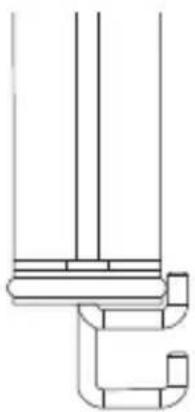
When shooting under windy conditions or when using a telephoto lens, the stability of your camera is critical. A built-in spring-loaded hook at the bottom of the center column allows you to hang a counterweight, such as a sandbag (not included) or loaded equipment bag (not included), to provide increased stabilization.

Warnings:
- Do not exceed the tripod's maximum load capacity (see tag on tripod).
- Ensure that all appropriate locks are engaged when necessary.
- Tripod should only be used in temperatures between -22^ and 140^ Fahrenheit.
- Do not operate in salt water. Dry tripod off if it becomes wet.
- Remove the camera from the tripod during transport.
- Keep out of reach of children.
- To avoid injury, always support the top of the center column with one hand while adjusting height and locking the knob with the other hand.
OPTIONAL ACCESSORIES
- TS-10 Deluxe Padded Neoprene Tripod Strap with zippered pocket
• TS-100 Padded Neoprene Tripod Strap
Visit our website at ObenSupports.com for more Oben products.
© Copyright 2014 The Gradus Group All other trademarks are the property of their respective owners
Brand : Oben
Model : AC-1451
Category : Tripod